2 Pole Motor - Ott Antriebe
12
DKM AC/DC Geared Motor and Gearhead B-56 2 Pole Motor Index 2 Pole Motor 15W (□80mm) 2 Pole Motor 25W (□80mm) 2 Pole Motor 40W (□90mm) 2 Pole Motor 60W (□90mm) 2 Pole Motor 90W (□90mm) 2 Pole Motor 120W (□90mm) 2 Pole Motor 150W (□90mm) 2 Pole Motor 200W (□90mm) B-57 B-59 B-61 B-63 B-65 B-67 B-69 B-71 2 Pole Motor Änderungen und Irrtümer auch technischer Art vorbehalten! OTT GmbH & Co. KG 78652 Deißlingen Tel.: 07420-9399-0 Fax.: 07420-9399-25 Email: [email protected]
Transcript of 2 Pole Motor - Ott Antriebe
DKM AC/DC Geared Motor and Gearhead B-56
2 Pole Motor
Index
2 Pole Motor 15W (□80mm)
2 Pole Motor 25W (□80mm)
2 Pole Motor 40W (□90mm)
2 Pole Motor 60W (□90mm)
2 Pole Motor 90W (□90mm)
2 Pole Motor 120W (□90mm)
2 Pole Motor 150W (□90mm)
2 Pole Motor 200W (□90mm)
B-57
B-59
B-61
B-63
B-65
B-67
B-69
B-71
2 Pole Motor
Terminal Box Type
Änderungen und Irrtümer auch technischer Art vorbehalten!
OTT GmbH & Co. KG 78652 Deißlingen Tel.: 07420-9399-0 Fax.: 07420-9399-25 Email: [email protected]
Manfred.Ott
Hervorheben
2 Pole Motor 60W (□90mm)
Manfred.Ott
Hervorheben
B-63
B AC Motors
B-01 AC Motors Technical Data of AC Motor
Technical Data of AC Motor
Definition of Motor
Types of Motor
Features of DKM AC Motor
Various and Abundant Models
Low Noise and Low Vibration
Easy to Use
Just-In-Time System
Classification by Power
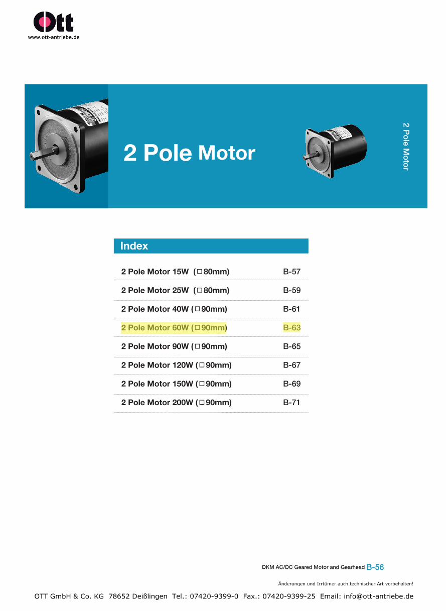
Motor is a machine to get a driving force for rotation or straight movement by converting the electrical energy into mechanical energy and the light-weighted motor which enables to select the model suitable for the load, has less noise and vibration as well as no exhaust pollution.
DKM AC geared motor was developed first in Korea in 1987 and has been used in a good reputation throughout the whole areas of domestic/overseas industry up to know. Our AC geared motor is proud of various and wide range of specification which satisfies various electrical requirements from all over the world.
There are various and abundant models in frame size covering □60/70/80/90mm such as Induction Motor, 2 Pole Motor, Reversible Motor, E.M. Brake Motor, Clutch & Brake Motor, Torque Motor and Speed Control Motor.
For use voltage, we have various voltage specification covering all areas in the globe: 100V 50/60Hz(Japan), 200V 50/60Hz(Japan), 110V 60Hz(Taiwan),220V 60Hz(Korea, Taiwan), 115V 60Hz(North America), 230V 50Hz(Europe, Oceania), 220V/240V 50Hz(South-East Asia)
Due to the enhancement of quality standard such as places and conditions for motors to use, the low noise and low vibration are required.
To satisfy theses conditions, we employed high precision of gear processing and skiving cutting method and we are making a rotor which is the root cause of vibration by verifying with balance machine for low noise and low vibration.
Easy and safe to use as motor and Gearbox are sold according to the requirements so that it can be designed and manufactured optimally.
It is easy to drive to get a driving force by connecting capacitor to the commercial power available to be used anywhere and anytime. As capacitor is not needed for three phase power, it is available to get a driving force easily by connecting three phase power to the motor directly.
Just-In-Time system is available in DKM Motor Co., Ltd. for the best delivery system. DKM realized user’s satisfaction with the world best delivery system.
AC motor: A motor operated by AC power. For example, inductive motor, synchronous motor, AC commutator motor etc.
DC motor: A motor which rotates by supplying the direct current to the armature. The torque generated by placing the coil between magnetic poles N and S and applying the current to this coil rotates the motor. Whenever this coil passes the neutral shaft, it turns the direction of current reversely androtates continuously
1) Single Phase Motor• Single phase power is composed of one phase as commercial power for home.• As power itself does not make motor rotate, capacitor is connected to auxiliary coil to start.
2) Three Phase Motor• Three phase motor stands for electrical power and it is consisted of three electrical sources with a phase offset of 120° in voltage.• Connect the power to motor to start and the rotor will start to run easily.• The efficiency of motor is high and the starting torque is relatively big.
Änderungen und Irrtümer auch technischer Art vorbehalten!
OTT GmbH & Co. KG 78652 Deißlingen Tel.: 07420-9399-0 Fax.: 07420-9399-25 Email: [email protected]
DKM AC/DC Geared Motor and Gearbox B-02
Technical Data of AC
Motor
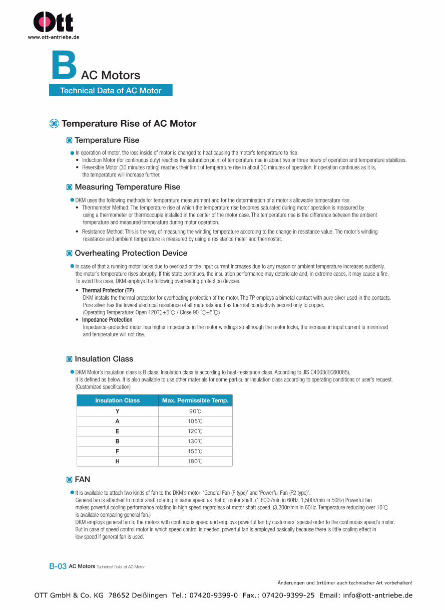
Structure of AC Motor
Classification by FunctionMotor with Constant Speed
Brake MotorIt is a motor embedded with fail-safe electromagnetic brake. Perfect braking enables to get a staying power. Brake runs only when the power is shutdown, so this is suitable as a brake for safe use.※ DKM has ‘A Type’ electronic brake motor which runs when the power is applied. (Customized specification)
Clutch & Brake MotorDKM Clutch & Brake motor is equipped with Clutch & Brake mechanism available to be used with Gearbox. As the continuously rotating induction motor and Clutch & Brake are combined, this can be used for frequent start/stop, position control, index operation and relative value feeding operation etc.
Torque MotorDKM torque motor has big starting torque and sloping characteristics. It runs safely over the whole area of rotation speed-torque characteristics. (Torque is highest at zero speed and decreases steadily with increasing speed.) With these characteristics, this can be used for more application as a winding or tension motor.
① Flange BracketDie-cast aluminum bracket is press-fitted into the motor case.The flange and the housing are a single body type which plays an important part to attach the motor alone or combine the Gearbox.
② StatorThis is comprised of a stator core made from laminated silicon/steelplates, a polyester-coated copper coil and insulation film. The roles are to generate magnetic field, form the rotation and run the rotor.
③ Motor CaseDie-cast aluminum with a machined finish inside
④ RotorIt is comprised of laminated silicon/steel plates with die-cast aluminum. Rotor plays the part to change the electric energy to mechanical energy and transfer it to outside through shaft.
⑤ Output ShaftThere are D-cut type shaft, key type shaft which are for using by motor itself and gear type shaft (pinion shaft) which is for attaching Gearbox. It is made by S45C with a machined finish.
⑥ Ball BearingIt ensures that the rotor remains at the right position for the reliability and fast rotational motion.
⑦ Lead WireLead wires with heat-resistant polyethylene coating
⑧ PaintingBacked finish of acrylic resin and melamine resin with beautiful look
Speed Control MotorUser can easily set and adjust the motor speed. There are three kinds of speed controller for AC speed motors. Select the best system depending upon your application.
1) Induction Motor: An induction motor is a type of AC motor where power is supplied to the rotor by means of electromagnetic induction.These motors are widely used in industrial drives, particularly polyphase induction motors, because they are rugged and have no brushes. Their speed is determined by the frequency of the supply current, so they are most widely used in constant-speed applications, although variable speed versions, using variable frequency drives are becoming more common.
2) Reversible Motor: A kind of induction motor and a motor having the same characteristic in any direction such as left turn or right turn.In principle, it is same as induction motor but there is no relation of main coil and auxiliary coil like general induction motor in order to stand frequent normal/reverse rotation and get a big starting torque.
Änderungen und Irrtümer auch technischer Art vorbehalten!
OTT GmbH & Co. KG 78652 Deißlingen Tel.: 07420-9399-0 Fax.: 07420-9399-25 Email: [email protected]
B AC Motors
B-03 AC Motors Technical Data of AC Motor
Technical Data of AC Motor
Temperature Rise of AC MotorTemperature Rise
Measuring Temperature Rise
Overheating Protection Device
Insulation Class
FAN
In operation of motor, the loss inside of motor is changed to heat causing the motor’s temperature to rise.• Induction Motor (for continuous duty) reaches the saturation point of temperature rise in about two or three hours of operation and temperature stabilizes.• Reversible Motor (30 minutes rating) reaches their limit of temperature rise in about 30 minutes of operation. If operation continues as it is,
the temperature will increase further.
DKM uses the following methods for temperature measurement and for the determination of a motor’s allowable temperature rise.• Thermometer Method: The temperature rise at which the temperature rise becomes saturated during motor operation is measured by
using a thermometer or thermocouple installed in the center of the motor case. The temperature rise is the difference between the ambient temperature and measured temperature during motor operation.
• Resistance Method: This is the way of measuring the winding temperature according to the change in resistance value. The motor’s winding resistance and ambient temperature is measured by using a resistance meter and thermostat.
In case of that a running motor locks due to overload or the input current increases due to any reason or ambient temperature increases suddenly, the motor’s temperature rises abruptly. If this state continues, the insulation performance may deteriorate and, in extreme cases, it may cause a fire. To avoid this case, DKM employs the following overheating protection devices.
• Thermal Protector (TP)DKM installs the thermal protector for overheating protection of the motor. The TP employs a bimetal contact with pure silver used in the contacts. Pure silver has the lowest electrical resistance of all materials and has thermal conductivity second only to copper. (Operating Temperature: Open 120℃±5℃ / Close 90 ℃±5℃)
• Impedance ProtectionImpedance-protected motor has higher impedance in the motor windings so although the motor locks, the increase in input current is minimized and temperature will not rise.
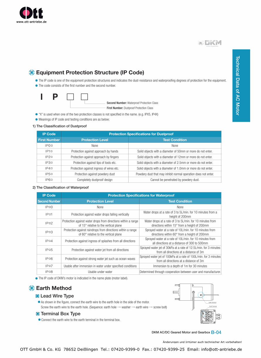
DKM Motor’s insulation class is B class. Insulation class is according to heat-resistance class. According to JIS C4003(IEC60085), it is defined as below. It is also available to use other materials for some particular insulation class according to operating conditions or user’s request. (Customized specification)
It is available to attach two kinds of fan to the DKM’s motor; ‘General Fan (F type)’ and ‘Powerful Fan (F2 type)’.General fan is attached to motor shaft rotating in same speed as that of motor shaft. (1,800r/min in 60Hz, 1,500r/min in 50Hz) Powerful fan makes powerful cooling performance rotating in high speed regardless of motor shaft speed. (3,200r/min in 60Hz. Temperature reducing over 10℃ is available comparing general fan.)DKM employs general fan to the motors with continuous speed and employs powerful fan by customers’ special order to the continuous speed’s motor. But in case of speed control motor in which speed control is needed, powerful fan is employed basically because there is little cooling effect in low speed if general fan is used.
Insulation Class Max. Permissible Temp.Y 90℃
A 105℃
E 120℃
B 130℃
F 155℃
H 180℃
Änderungen und Irrtümer auch technischer Art vorbehalten!
OTT GmbH & Co. KG 78652 Deißlingen Tel.: 07420-9399-0 Fax.: 07420-9399-25 Email: [email protected]
DKM AC/DC Geared Motor and Gearbox B-04
The IP code is one of the equipment protection structures and indicates the dust-resistance and waterproofing degrees of protection for the equipment.
The code consists of the first number and the second number.
“X” is used when one of the two protection classes is not specified in the name. (e.g. IPX5, IP4X)
Meanings of IP code and testing conditions are as below;
Second Number: Waterproof Protection Class
First Number: Dustproof Protection Class
Technical Data of AC
Motor
Earth Method
Equipment Protection Structure (IP Code)
Lead Wire Type
Terminal Box Type
The IP code of DKM’s motor is indicated in the name plate (motor label).
In operation of motor, the loss inside of motor is changed to heat causing the motor’s temperature to rise.• Induction Motor (for continuous duty) reaches the saturation point of temperature rise in about two or three hours of operation and temperature stabilizes.• Reversible Motor (30 minutes rating) reaches their limit of temperature rise in about 30 minutes of operation. If operation continues as it is,
the temperature will increase further.
As shown in the figure, connect the earth wire to the earth hole in the side of the motor.
Screw the earth wire to the earth hole. (Sequence: earth hole → washer → earth wire → screw bolt)
Connect the earth wire to the earth terminal in the terminal box.
IP Code Protection Specifications for DustproofFirst Number Protection Level Test Condition
IP0□ None None
IP1□ Protection against approach by hands Solid objects with a diameter of 50mm or more do not enter.
IP2□ Protection against approach by fingers Solid objects with a diameter of 12mm or more do not enter.
IP3□ Protection against tips of tools etc. Solid objects with a diameter of 2.5mm or more do not enter.
IP4□ Protection against ingress of wires etc. Solid objects with a diameter of 1.0mm or more do not enter.
IP5□ Protection against powdery dust Powdery dust that may inhibit normal operation does not enter.
IP6□ Completely dustproof design Cannot be penetrated by powdery dust.
IP Code Protection Specifications for WaterproofSecond Number Protection Level Test Condition
IP□0 None None
IP□1 Protection against water drops falling verticallyWater drops at a rate of 3 to 5L/min. for 10 minutes from a
height of 200mm
IP□2Protection against water drops from directions within a range
of 15° relative to the vertical planeWater drops at a rate of 3 to 5L/min. for 10 minutes from
directions within 15° from a height of 200mm
IP□3Protection against raindrops from directions within a range
of 60° relative to the vertical planeSprayed water at a rate of 10L/min. for 10 minutes from
directions within 60° from a height of 200mm
IP□4 Protection against ingress of splashes from all directionsSprayed water at a rate of 10L/min. for 10 minutes from
all directions at a distance of 300 to 500mm
IP□5 Protection against water jet from all directionsSprayed water jet of 30kPa at a rate of 12.5L/min. for 3 minutes
from all directions at a distance of 3m
IP□6 Protection against strong water jet such as ocean wavesSprayed water jet of 100kPa at a rate of 100L/min. for 3 minutes
from all directions at a distance of 3mIP□7 Usable after immersion in water under specified conditions Immersion to a depth of 1m for 30 minutes
IP□8 Usable under water Determined through cooperation between user and manufacturer.
I P
1) The Classification of Dustproof
2) The Classification of Waterproof
Änderungen und Irrtümer auch technischer Art vorbehalten!
OTT GmbH & Co. KG 78652 Deißlingen Tel.: 07420-9399-0 Fax.: 07420-9399-25 Email: [email protected]
B AC Motors
B-07 AC Motors Induction Motor
Outline of Induction Motor
Suitable for Unidirectional Continuous Operation
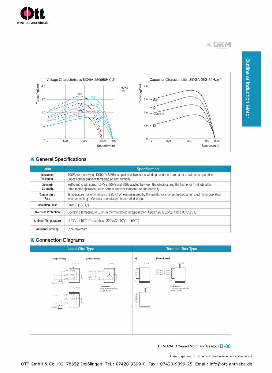
Features of Voltage and Capacitor
Induction motors are suitable for unidirectional continuous operation such as conveyor belt system.
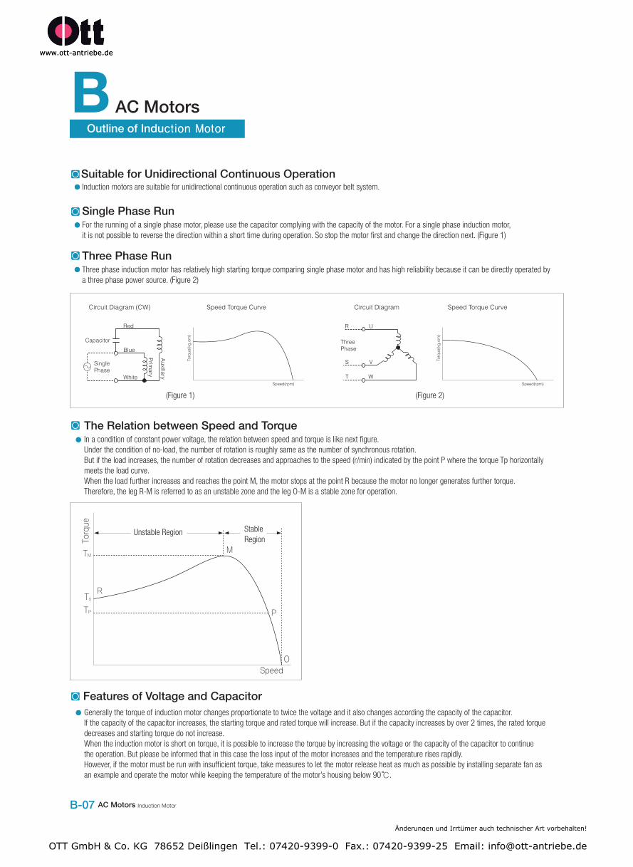
Single Phase RunFor the running of a single phase motor, please use the capacitor complying with the capacity of the motor. For a single phase induction motor, it is not possible to reverse the direction within a short time during operation. So stop the motor first and change the direction next. (Figure 1)
Three Phase RunThree phase induction motor has relatively high starting torque comparing single phase motor and has high reliability because it can be directly operated by a three phase power source. (Figure 2)
The Relation between Speed and TorqueIn a condition of constant power voltage, the relation between speed and torque is like next figure.Under the condition of no-load, the number of rotation is roughly same as the number of synchronous rotation.But if the load increases, the number of rotation decreases and approaches to the speed (r/min) indicated by the point P where the torque Tp horizontally meets the load curve.When the load further increases and reaches the point M, the motor stops at the point R because the motor no longer generates further torque. Therefore, the leg R-M is referred to as an unstable zone and the leg O-M is a stable zone for operation.
Generally the torque of induction motor changes proportionate to twice the voltage and it also changes according the capacity of the capacitor.If the capacity of the capacitor increases, the starting torque and rated torque will increase. But if the capacity increases by over 2 times, the rated torquedecreases and starting torque do not increase.When the induction motor is short on torque, it is possible to increase the torque by increasing the voltage or the capacity of the capacitor to continue the operation. But please be informed that in this case the loss input of the motor increases and the temperature rises rapidly.However, if the motor must be run with insufficient torque, take measures to let the motor release heat as much as possible by installing separate fan as an example and operate the motor while keeping the temperature of the motor’s housing below 90℃.
(Figure 1) (Figure 2)
Speed
Torque
TM
Ts
R
Unstable Region Stable Region
P
O
M
TP
Änderungen und Irrtümer auch technischer Art vorbehalten!
OTT GmbH & Co. KG 78652 Deißlingen Tel.: 07420-9399-0 Fax.: 07420-9399-25 Email: [email protected]
DKM AC/DC Geared Motor and Gearbox B-08
Outline of Indu
ctio
n M
oto
r
General Specifications
Connection Diagrams
Item SpecificationInsulation Resistance
100㏁ or more when DC500V MEGA is applied between the windings and the frame after rated motor operation under normal ambient temperature and humidity.
Dielectric Strength
Sufficient to withstand 1.5KV at 50Hz and 60Hz applied between the windings and the frame for 1 minute after rated motor operation under normal ambient temperature and humidity.
Temperature Rise
Temperature rise of windings are 80℃ or less measured by the resistance change method after rated motor operation with connecting a Gearbox or equivalent heat radiation plate.
Insulation Class Class B [130℃]
Overheat Protection Operating temperature (Built-in thermal protector type motor): Open 120℃±5℃, Close 90℃±5℃
Ambient Temperature -10℃~+40℃ (Three phase 220VAC: -10℃~+50℃)
Ambient Humidity 85% maximum
Lead Wire Type Terminal Box Type
Änderungen und Irrtümer auch technischer Art vorbehalten!
OTT GmbH & Co. KG 78652 Deißlingen Tel.: 07420-9399-0 Fax.: 07420-9399-25 Email: [email protected]
A Information
A-01 Information Product Coding System
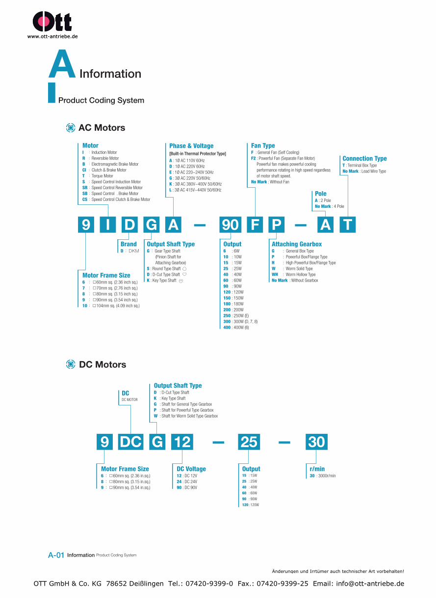
AC Motors
DC Motors
9 I D G A 90 F P A T
Motor Frame Size6 :□60mm sq. (2.36 inch sq.)7 :□70mm sq. (2.76 inch sq.)8 :□80mm sq. (3.15 inch sq.)9 :□90mm sq. (3.54 inch sq.)10:□104mm sq. (4.09 inch sq.)
MotorI :Induction MotorR :Reversible MotorB :Electromagnetic Brake MotorCI :Clutch & Brake MotorT :Torque MotorS :Speed Control Induction MotorSR:Speed Control Reversible MotorSB:Speed Control . Brake MotorCS:Speed Control Clutch & Brake Motor
Brand D:DKM
Phase & Voltage[Built-in Thermal Protector Type]
A : 1Ø AC 110V 60HzD : 1Ø AC 220V 60HzE : 1Ø AC 220~240V 50HzG : 3Ø AC 220V 50/60HzK : 3Ø AC 380V~400V 50/60HzL : 3Ø AC 415V~440V 50/60Hz
Output6 : 6W10 : 10W15 : 15W25 : 25W40 : 40W60 : 60W90 : 90W120 : 120W150 : 150W180 : 180W200 : 200W250 : 250W (E)300 : 300W (D, 7, 8)400 : 400W (6)
Fan TypeF : General Fan (Self Cooling)F2 : Powerful Fan (Separate Fan Motor)
Powerful fan makes powerful coolingperformance rotating in high speed regardlessof motor shaft speed.
No Mark : Without Fan
Attaching GearboxG : General Box TypeP : Powerful Box/Flange TypeH : High Powerful Box/Flange TypeW : Worm Solid TypeWH : Worm Hollow TypeNo Mark : Without Gearbox
Pole A : 2 PoleNo Mark : 4 Pole
Connection TypeT : Terminal Box TypeNo Mark : Lead Wire Type
Output Shaft TypeG:Gear Type Shaft
(Pinion Shaft for Attaching Gearbox)
S : Round Type ShaftD : D-Cut Type Shaft K : Key Type Shaft
9 G 25 3012DC
Motor Frame Size6:□60mm sq. (2.36 in.sq.)8:□80mm sq. (3.15 in.sq.)9:□90mm sq. (3.54 in.sq.)
Output Shaft TypeD : D-Cut Type ShaftK : Key Type ShaftG : Shaft for General Type GearboxP : Shaft for Powerful Type GearboxW : Shaft for Worm Solid Type Gearbox
DC Voltage12 : DC 12V24 : DC 24V90 : DC 90V
DCDC MOTOR
Output15 : 15W
25 : 25W
40 : 40W
60 : 60W
90 : 90W
120 : 120W
r/min30 : 3000r/min
Product Coding System
Änderungen und Irrtümer auch technischer Art vorbehalten!
OTT GmbH & Co. KG 78652 Deißlingen Tel.: 07420-9399-0 Fax.: 07420-9399-25 Email: [email protected]
DKM AC/DC Geared Motor and Gearbox A-02
Pro
duct C
od
ing S
ystem
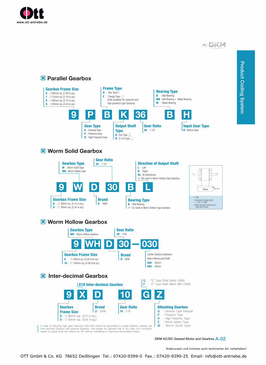
Parallel Gearbox
Inter-decimal Gearbox
9 X D 10 G ZGearbox Frame Size 8:□80mmsq.(3.15in.sq.)
9:□90mmsq.(3.54in.sq.)
X10 Inter-decimal Gearbox
Gear Ratio 10:1/10
Attaching Gearbox G :GeneralType(Helical)
P :PowerfulType
H :HighPowerfulType
Z :WormHollowType
W :WormSolidtype
G :"G"TypeShaftMotor(40W)
P :"P"TypeShaftMotor(60~120W)
BrandD:DKM
9 P B K 36 B H
Gearbox Frame Size 6 : □60mm sq. (2.36 in.sq.)7 : □70mm sq. (2.76 in.sq.)8 : □80mm sq. (3.15 in.sq.)9 : □90mm sq. (3.54 in.sq.)
Gear Type G : General GearP : Powerful GearH : High Powerful Gear
Frame TypeB:Box Type□
F:Flange Type(Only available for powerful and high powerful type Gearbox)
Bearing Type B : Ball BearingBM : Ball Bearing + Metal Bearing M : Metal Bearing
Input Gear Type H : Helical Gear
Gear Ratio 36:1/36
Output Shaft TypeK : Key TypeD : D-Cut Type
Worm Solid Gearbox
Gearbox Type W : Worm Solid TypeWH : Worm Hollow Type
9 W D 30 B LGearbox Frame Size8:□80mm sq. (3.15 in.sq.)9:□90mm sq. (3.54 in.sq.)
BrandD:DKM
Gear Ratio 30:1/30
Bearing Type B:Ball Bearing※No mark in Worm Hollow Type Gearbox
Direction of Output ShaftL : LeftR : RightRL : Bi-directional※No mark in Worm Hollow Type Gearbox
※Ref.1. Direction of Output Shaft -
L : Left R : Right2. When direction of lead wire is
right side of motor.
IncaseofrequiringhighgearreductionratiothatcannotbegeneratedbysingleGearbox,pleaseuseInter-decimalGearboxwithgeneralGearbox.Andpleasebeadvisedthatinthiscaseonlyrevolutionspeedofoutputshaftwillreduceby10:1withoutincreasingofmaximumpermissibletorque.
Worm Hollow Gearbox
Center Distance between
Worm Wheel and Shaft
030:30mm040:40mm
9 D 30WH 030Gearbox Frame Size9 :□ 90mm sq. (4.09 inch.sq.)10:□ 104mm sq. (4.09 inch.sq.)
Gearbox Type WH:Worm Hollow Gearbox
BrandD:DKM
Gear Ratio 30:1/30
Änderungen und Irrtümer auch technischer Art vorbehalten!
OTT GmbH & Co. KG 78652 Deißlingen Tel.: 07420-9399-0 Fax.: 07420-9399-25 Email: [email protected]
A Information
A-03 Information Product Coding System
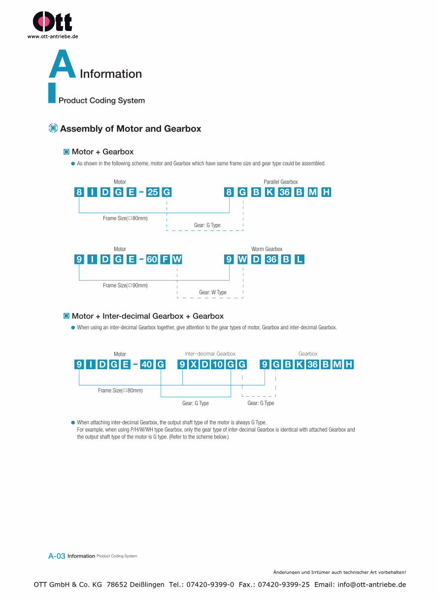
Assembly of Motor and Gearbox
Motor + Inter-decimal Gearbox + Gearbox
As shown in the following scheme, motor and Gearbox which have same frame size and gear type could be assembled.
When using an inter-decimal Gearbox together, give attention to the gear types of motor, Gearbox and inter-decimal Gearbox.
When attaching inter-decimal Gearbox, the output shaft type of the motor is always G Type.For example, when using P/H/W/WH type Gearbox, only the gear type of inter-decimal Gearbox is identical with attached Gearbox andthe output shaft type of the motor is G type. (Refer to the scheme below.)
Motor + Gearbox
8 8 BI G MD B HG KE G25 36Motor
Frame Size(□80mm)Gear: G Type
Parallel Gearbox
9 9 BI W LD DG E WF60 36Motor
Frame Size(□90mm)Gear: W Type
Worm Gearbox
9 9 B9 GI G MX GD B HDG KE G40 10 36Motor
Frame Size(□80mm)
Gear: G TypeGear: G Type
GearboxInter-decimalGearbox
Product Coding System
Änderungen und Irrtümer auch technischer Art vorbehalten!
OTT GmbH & Co. KG 78652 Deißlingen Tel.: 07420-9399-0 Fax.: 07420-9399-25 Email: [email protected]
B AC Motors
B-63 AC Motors 2 Pole Motor
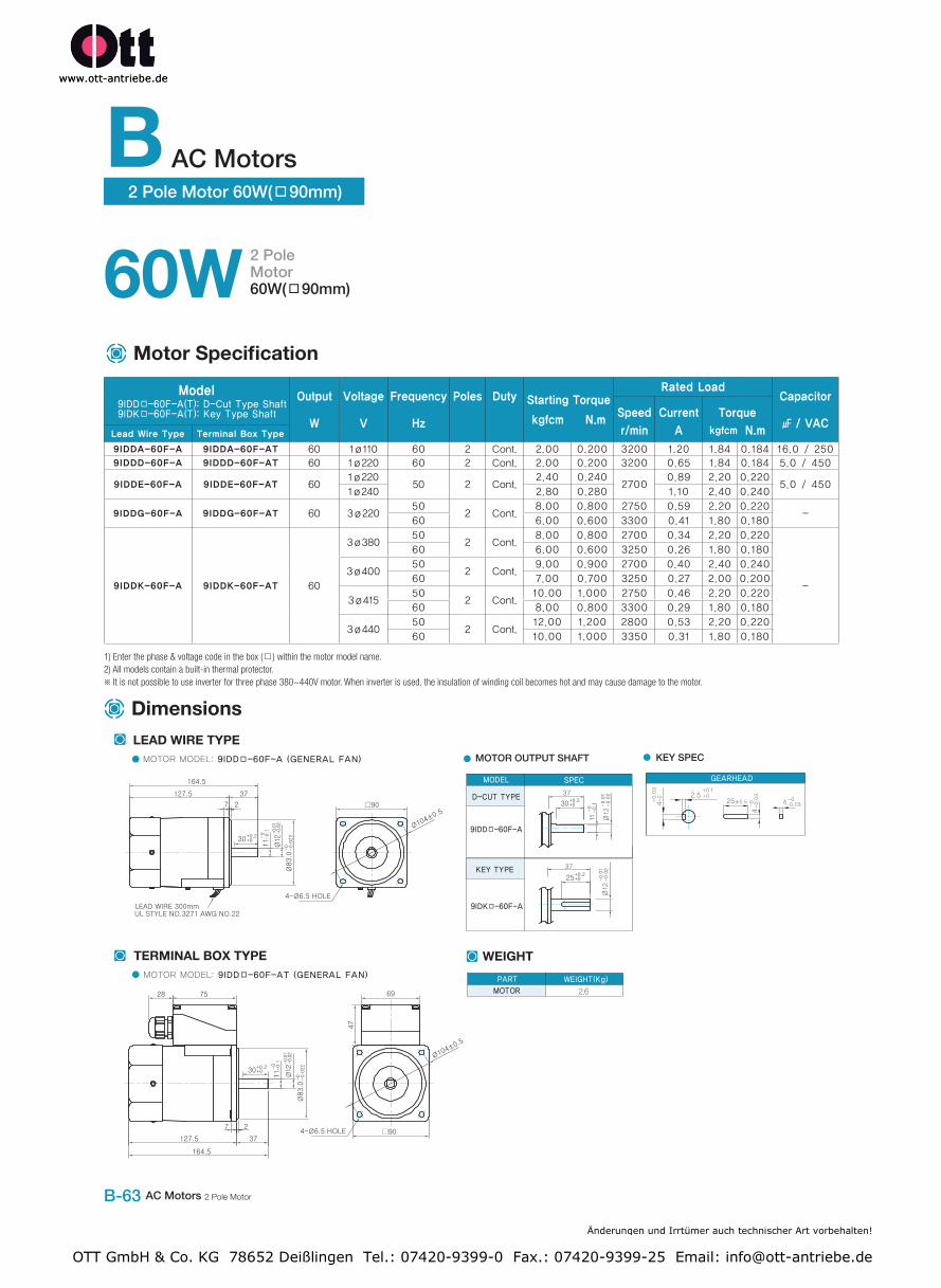
2 Pole Motor 60W(□90mm)
Motor Specification
60W 2 Pole Motor60W(□90mm)
Dimensions
Model9IDD□-60F-A(T): D-Cut Type Shaft9IDK□-60F-A(T): Key Type Shaft
Output
W
Voltage
V
Frequency
Hz
Poles Duty Starting Torque
kgfcm N.m
Rated LoadCapacitor
㎌ / VACSpeed
r/min
Current
A
Torque
kgfcm N.mLead Wire Type Terminal Box Type
9IDDA-60F-A 9IDDA-60F-AT 60 1ø110 60 2 Cont. 2.00 0.200 3200 1.20 1.84 0.184 16.0 / 250
9IDDD-60F-A 9IDDD-60F-AT 60 1ø220 60 2 Cont. 2.00 0.200 3200 0.65 1.84 0.184 5.0 / 450
9IDDE-60F-A 9IDDE-60F-AT 601ø220
50 2 Cont.2.40 0.240
27000.89 2.20 0.220
5.0 / 4501ø240 2.80 0.280 1.10 2.40 0.240
9IDDG-60F-A 9IDDG-60F-AT 60 3ø22050
2 Cont.8.00 0.800 2750 0.59 2.20 0.220
-60 6.00 0.600 3300 0.41 1.80 0.180
9IDDK-60F-A 9IDDK-60F-AT 60
3ø38050
2 Cont.8.00 0.800 2700 0.34 2.20 0.220
-
60 6.00 0.600 3250 0.26 1.80 0.180
3ø40050
2 Cont.9.00 0.900 2700 0.40 2.40 0.240
60 7.00 0.700 3250 0.27 2.00 0.200
3ø41550
2 Cont.10.00 1.000 2750 0.46 2.20 0.220
60 8.00 0.800 3300 0.29 1.80 0.180
3ø44050
2 Cont.12.00 1.200 2800 0.53 2.20 0.220
60 10.00 1.000 3350 0.31 1.80 0.180
1) Enter the phase & voltage code in the box (□) within the motor model name.2) All models contain a built-in thermal protector.※ It is not possible to use inverter for three phase 380~440V motor. When inverter is used, the insulation of winding coil becomes hot and may cause damage to the motor.
Änderungen und Irrtümer auch technischer Art vorbehalten!
OTT GmbH & Co. KG 78652 Deißlingen Tel.: 07420-9399-0 Fax.: 07420-9399-25 Email: [email protected]
DKM AC/DC Geared Motor and Gearhead B-64
2 Pole Motor 60W
( □90m
m)
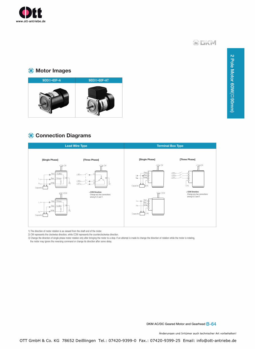
9IDD□-60F-A 9IDD□-60F-AT
Motor Images
Lead Wire Type Terminal Box Type
1) The direction of motor rotation is as viewed from the shaft end of the motor.2) CW represents the clockwise direction, while CCW represents the counterclockwise direction.3) Change the direction of single phase motor rotation only after bringing the motor to a stop. If an attempt is made to change the direction of rotation while the motor is rotating,
the motor may ignore the reversing command or change its direction after some delay.
Connection Diagrams
Änderungen und Irrtümer auch technischer Art vorbehalten!
OTT GmbH & Co. KG 78652 Deißlingen Tel.: 07420-9399-0 Fax.: 07420-9399-25 Email: [email protected]