7149 073-1-7149 Rev. 1 0073-1- · GER 5 2 Sicherheit Arbeiten am 230 V Netz dürfen nur von...
93
0073-1-7149 Rev. 1 0073-1-7149 Controlpanel 6136/100C-102 6936/100C-102 Controlpanel 6136/100CB-102 6936/100CB-102 GER Bedienungsanleitung ENG Operating Instructions 29.04.2009 FRA Mode d'emploi dans votre langue v. page 5 DUT Bedieningshandleiding zie pagina 5 NOR Bruksanvisning Norsk se side 5 SWE Bruksanvisning se sida 5 FIN Käyttöohjeet suomeksi katso sivu numero 5 CHI 中文操作说明在第5页
Transcript of 7149 073-1-7149 Rev. 1 0073-1- · GER 5 2 Sicherheit Arbeiten am 230 V Netz dürfen nur von...
0073-1-7149 Rev. 1
0073
-1-7
149
Controlpanel 6136/100C-102 6936/100C-102 Controlpanel 6136/100CB-102
6936/100CB-102
GER Bedienungsanleitung ENG Operating Instructions
29.04.2009
FRA Mode d'emploi dans votre langue v. page 5 DUT Bedieningshandleiding zie pagina 5 NOR Bruksanvisning Norsk se side 5 SWE Bruksanvisning se sida 5 FIN Käyttöohjeet suomeksi katso sivu numero 5 CHI 中文操作说明在第5页

GER
3
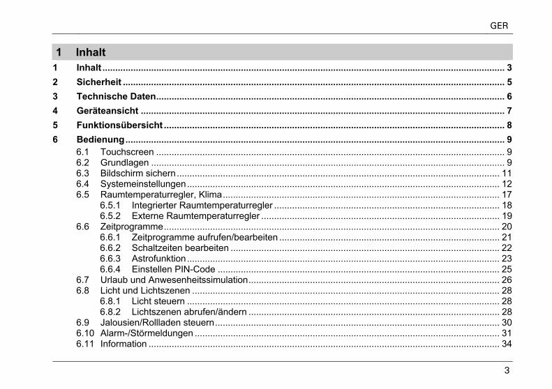
1 Inhalt 1 Inhalt ............................................................................................................................................................. 3 2 Sicherheit ..................................................................................................................................................... 5 3 Technische Daten........................................................................................................................................ 6 4 Geräteansicht .............................................................................................................................................. 7 5 Funktionsübersicht ..................................................................................................................................... 8 6 Bedienung.................................................................................................................................................... 9
6.1 Touchscreen ........................................................................................................................................ 9 6.2 Grundlagen .......................................................................................................................................... 9 6.3 Bildschirm sichern.............................................................................................................................. 11 6.4 Systemeinstellungen.......................................................................................................................... 12 6.5 Raumtemperaturregler, Klima............................................................................................................ 17
6.5.1 Integrierter Raumtemperaturregler ........................................................................................ 18 6.5.2 Externe Raumtemperaturregler ............................................................................................. 19
6.6 Zeitprogramme................................................................................................................................... 20 6.6.1 Zeitprogramme aufrufen/bearbeiten ...................................................................................... 21 6.6.2 Schaltzeiten bearbeiten ......................................................................................................... 22 6.6.3 Astrofunktion.......................................................................................................................... 23 6.6.4 Einstellen PIN-Code .............................................................................................................. 25
6.7 Urlaub und Anwesenheitssimulation.................................................................................................. 26 6.8 Licht und Lichtszenen ........................................................................................................................ 28
6.8.1 Licht steuern .......................................................................................................................... 28 6.8.2 Lichtszenen abrufen/ändern .................................................................................................. 28
6.9 Jalousien/Rollladen steuern............................................................................................................... 30 6.10 Alarm-/Störmeldungen ....................................................................................................................... 31 6.11 Information ......................................................................................................................................... 34
GER
4
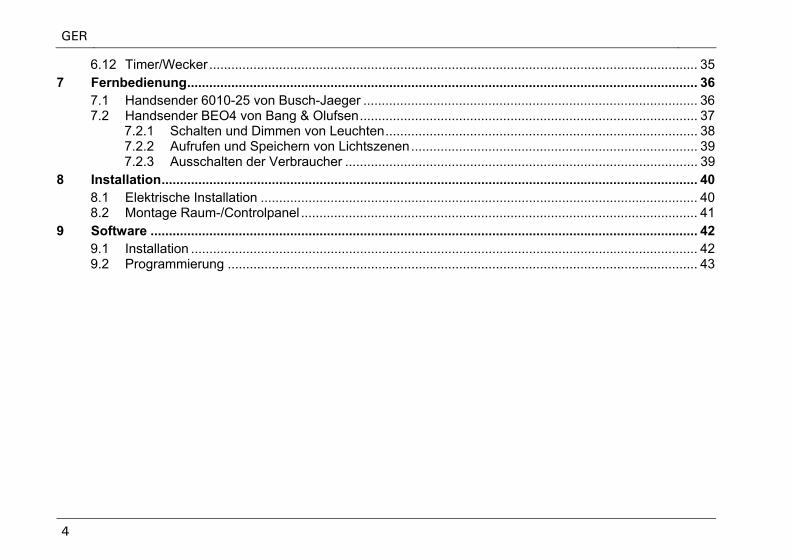
6.12 Timer/Wecker ..................................................................................................................................... 35 7 Fernbedienung........................................................................................................................................... 36
7.1 Handsender 6010-25 von Busch-Jaeger ........................................................................................... 36 7.2 Handsender BEO4 von Bang & Olufsen............................................................................................ 37
7.2.1 Schalten und Dimmen von Leuchten..................................................................................... 38 7.2.2 Aufrufen und Speichern von Lichtszenen.............................................................................. 39 7.2.3 Ausschalten der Verbraucher ................................................................................................ 39
8 Installation.................................................................................................................................................. 40 8.1 Elektrische Installation ....................................................................................................................... 40 8.2 Montage Raum-/Controlpanel ............................................................................................................ 41
9 Software ..................................................................................................................................................... 42 9.1 Installation .......................................................................................................................................... 42 9.2 Programmierung ................................................................................................................................ 43
GER
5
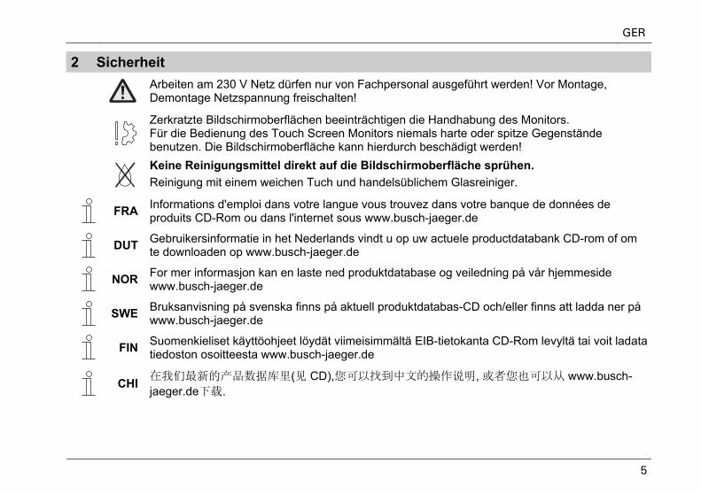
2 Sicherheit
Arbeiten am 230 V Netz dürfen nur von Fachpersonal ausgeführt werden! Vor Montage, Demontage Netzspannung freischalten!
Zerkratzte Bildschirmoberflächen beeinträchtigen die Handhabung des Monitors. Für die Bedienung des Touch Screen Monitors niemals harte oder spitze Gegenstände benutzen. Die Bildschirmoberfläche kann hierdurch beschädigt werden!
Keine Reinigungsmittel direkt auf die Bildschirmoberfläche sprühen. Reinigung mit einem weichen Tuch und handelsüblichem Glasreiniger.
FRA Informations d'emploi dans votre langue vous trouvez dans votre banque de données de
produits CD-Rom ou dans l'internet sous www.busch-jaeger.de
DUT Gebruikersinformatie in het Nederlands vindt u op uw actuele productdatabank CD-rom of om
te downloaden op www.busch-jaeger.de
NOR For mer informasjon kan en laste ned produktdatabase og veiledning på vår hjemmeside
www.busch-jaeger.de
SWE Bruksanvisning på svenska finns på aktuell produktdatabas-CD och/eller finns att ladda ner på
www.busch-jaeger.de
FIN Suomenkieliset käyttöohjeet löydät viimeisimmältä EIB-tietokanta CD-Rom levyltä tai voit ladata
tiedoston osoitteesta www.busch-jaeger.de
CHI 在我们最新的产品数据库里(见 CD),您可以找到中文的操作说明, 或者您也可以从 www.busch-
jaeger.de下载.
GER
6
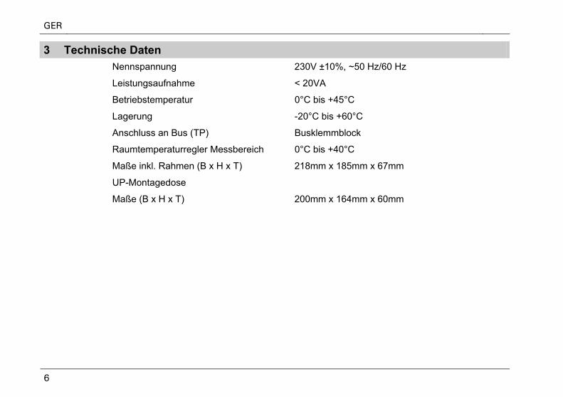
3 Technische Daten Nennspannung 230V ±10%, ~50 Hz/60 Hz
Leistungsaufnahme < 20VA
Betriebstemperatur 0°C bis +45°C
Lagerung -20°C bis +60°C
Anschluss an Bus (TP) Busklemmblock
Raumtemperaturregler Messbereich 0°C bis +40°C
Maße inkl. Rahmen (B x H x T) 218mm x 185mm x 67mm
UP-Montagedose
Maße (B x H x T) 200mm x 164mm x 60mm
GER
7
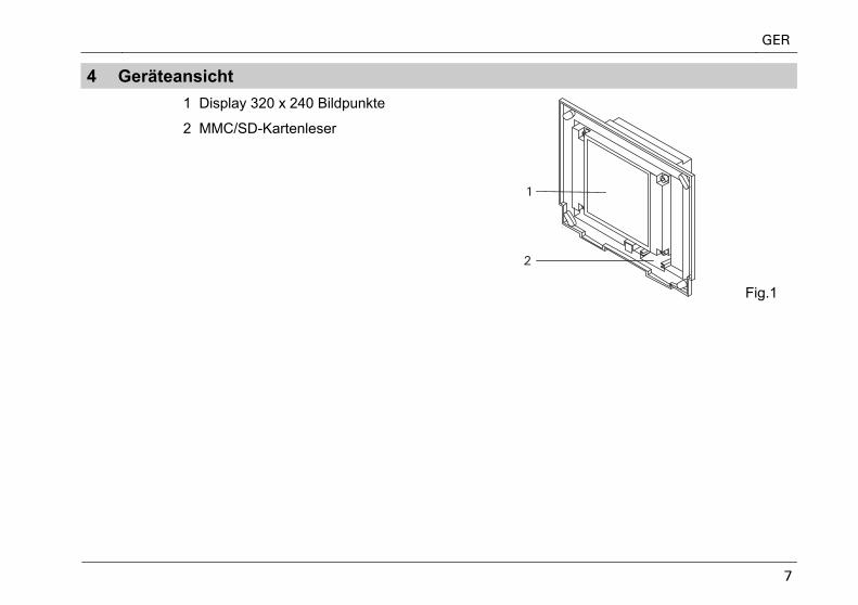
4 Geräteansicht
1 Display 320 x 240 Bildpunkte
2 MMC/SD-Kartenleser
Fig.1
GER
8
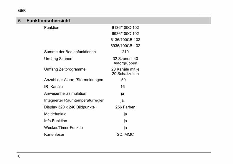
5 Funktionsübersicht
Funktion 6136/100C-102
6936/100C-102
6136/100CB-102
6936/100CB-102
Summe der Bedienfunktionen 210
Umfang Szenen 32 Szenen, 40 Aktorgruppen
Umfang Zeitprogramme 20 Kanäle mit je 20 Schaltzeiten
Anzahl der Alarm-/Störmeldungen 50
IR- Kanäle 16
Anwesenheitssimulation ja
Integrierter Raumtemperaturregler ja
Display 320 x 240 Bildpunkte 256 Farben
Meldefunktio ja
Info-Funktion ja
Wecker/Timer-Funktio ja
Kartenleser SD, MMC
GER
9
6 Bedienung
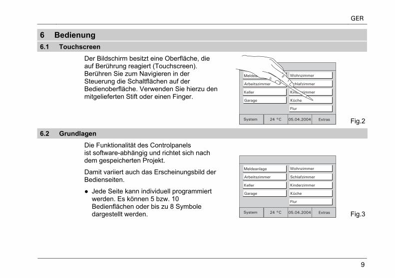
6.1 Touchscreen
Der Bildschirm besitzt eine Oberfläche, die auf Berührung reagiert (Touchscreen). Berühren Sie zum Navigieren in der Steuerung die Schaltflächen auf der Bedienoberfläche. Verwenden Sie hierzu den mitgelieferten Stift oder einen Finger.
Fig.2
6.2 Grundlagen
Die Funktionalität des Controlpanels ist software-abhängig und richtet sich nach dem gespeicherten Projekt.
Damit variiert auch das Erscheinungsbild der Bedienseiten.
● Jede Seite kann individuell programmiert werden. Es können 5 bzw. 10 Bedienflächen oder bis zu 8 Symbole dargestellt werden. Fig.3
GER
10
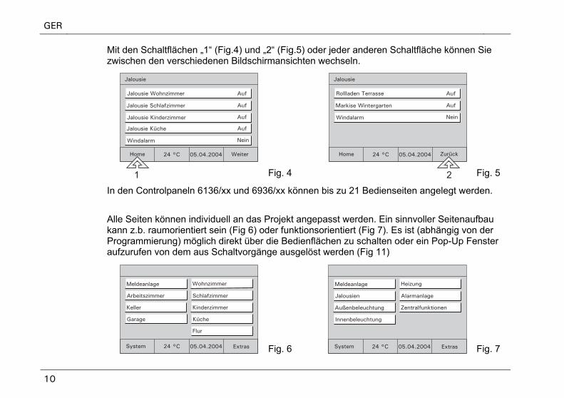
Mit den Schaltflächen „1“ (Fig.4) und „2“ (Fig.5) oder jeder anderen Schaltfläche können Sie zwischen den verschiedenen Bildschirmansichten wechseln.
Fig. 4 Fig. 5
In den Controlpaneln 6136/xx und 6936/xx können bis zu 21 Bedienseiten angelegt werden.
Alle Seiten können individuell an das Projekt angepasst werden. Ein sinnvoller Seitenaufbau kann z.b. raumorientiert sein (Fig 6) oder funktionsorientiert (Fig 7). Es ist (abhängig von der Programmierung) möglich direkt über die Bedienflächen zu schalten oder ein Pop-Up Fenster aufzurufen von dem aus Schaltvorgänge ausgelöst werden (Fig 11)
Fig. 6 Fig. 7
GER
11
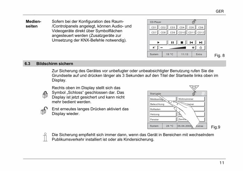
Medien-seiten
Sofern bei der Konfiguration des Raum-/Controlpanels angelegt, können Audio- und Videogeräte direkt über Symbolflächen angesteuert werden (Zusatzgeräte zur Umsetzung der KNX-Befehle notwendig).
Fig. 8
6.3 Bildschirm sichern
Zur Sicherung des Gerätes vor unbefugter oder unbeabsichtigter Benutzung rufen Sie die Grundseite auf und drücken länger als 3 Sekunden auf den Titel der Startseite links oben im Display.
Rechts oben im Display stellt sich das Symbol „Schloss“ geschlossen dar. Das Display ist jetzt gesichert und kann nicht mehr bedient werden.
Erst erneutes langes Drücken aktiviert das Display wieder.
Fig.9
Die Sicherung empfiehlt sich immer dann, wenn das Gerät in Bereichen mit wechselndem Publikumsverkehr installiert ist oder als Kindersicherung.
GER
12
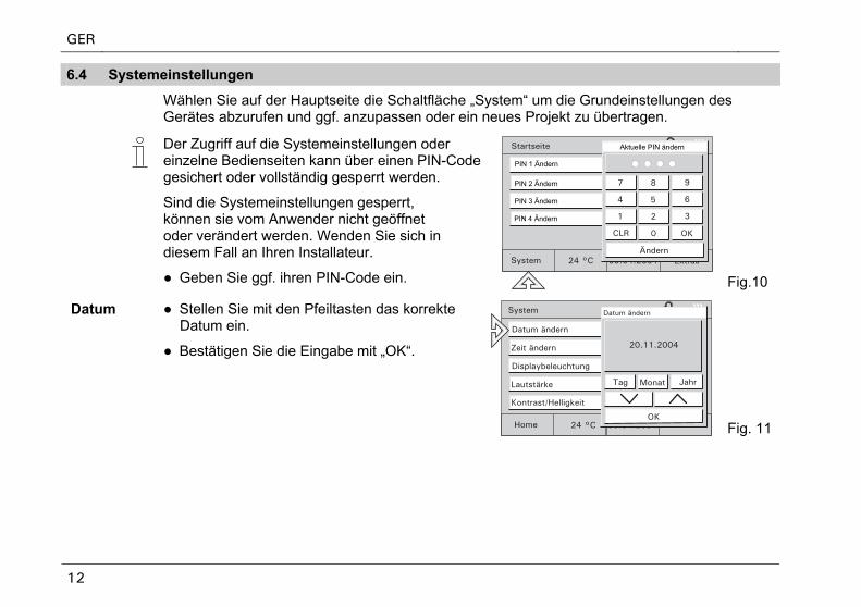
6.4 Systemeinstellungen
Wählen Sie auf der Hauptseite die Schaltfläche „System“ um die Grundeinstellungen des Gerätes abzurufen und ggf. anzupassen oder ein neues Projekt zu übertragen.
Der Zugriff auf die Systemeinstellungen oder einzelne Bedienseiten kann über einen PIN-Codegesichert oder vollständig gesperrt werden.
Sind die Systemeinstellungen gesperrt, können sie vom Anwender nicht geöffnet oder verändert werden. Wenden Sie sich in diesem Fall an Ihren Installateur.
● Geben Sie ggf. ihren PIN-Code ein.
Aktuelle PIN ändern
PIN 1 Ändern
PIN 2 Ändern
PIN 3 Ändern
PIN 4 Ändern
Fig.10
Datum ● Stellen Sie mit den Pfeiltasten das korrekte Datum ein.
● Bestätigen Sie die Eingabe mit „OK“.
Fig. 11
GER
13
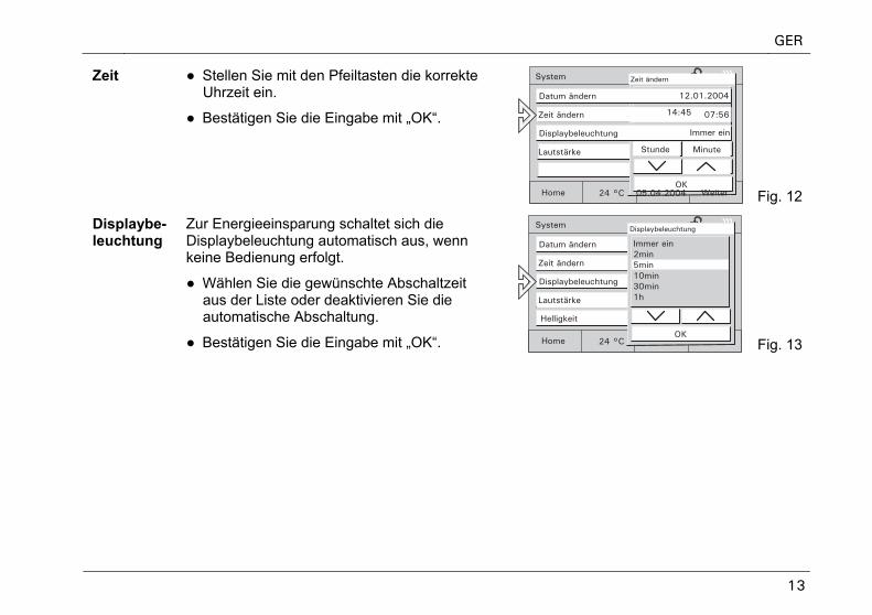
Zeit ● Stellen Sie mit den Pfeiltasten die korrekte Uhrzeit ein.
● Bestätigen Sie die Eingabe mit „OK“.
Fig. 12
Displaybe-leuchtung
Zur Energieeinsparung schaltet sich die Displaybeleuchtung automatisch aus, wenn keine Bedienung erfolgt.
● Wählen Sie die gewünschte Abschaltzeit aus der Liste oder deaktivieren Sie die automatische Abschaltung.
● Bestätigen Sie die Eingabe mit „OK“. Fig. 13
GER
14
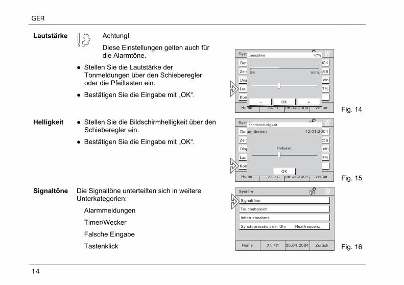
Achtung!
Diese Einstellungen gelten auch für die Alarmtöne.
Lautstärke
● Stellen Sie die Lautstärke der Tonmeldungen über den Schieberegler oder die Pfeiltasten ein.
● Bestätigen Sie die Eingabe mit „OK“.
Fig. 14
Helligkeit
● Stellen Sie die Bildschirmhelligkeit über den Schieberegler ein.
● Bestätigen Sie die Eingabe mit „OK“.
Fig. 15
Signaltöne Die Signaltöne unterteilten sich in weitere Unterkategorien:
Alarmmeldungen
Timer/Wecker
Falsche Eingabe
Tastenklick Fig. 16
GER
15
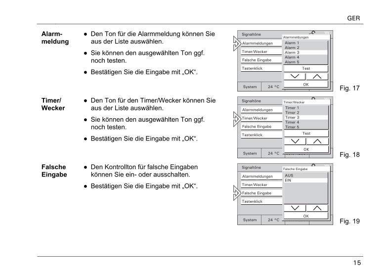
Alarm-meldung
● Den Ton für die Alarmmeldung können Sie aus der Liste auswählen.
● Sie können den ausgewählten Ton ggf. noch testen.
● Bestätigen Sie die Eingabe mit „OK“.
Fig. 17
Timer/ Wecker
● Den Ton für den Timer/Wecker können Sie aus der Liste auswählen.
● Sie können den ausgewählten Ton ggf. noch testen.
● Bestätigen Sie die Eingabe mit „OK“.
Fig. 18
Falsche Eingabe
● Den Kontrollton für falsche Eingaben können Sie ein- oder ausschalten.
● Bestätigen Sie die Eingabe mit „OK“.
Fig. 19
GER
16
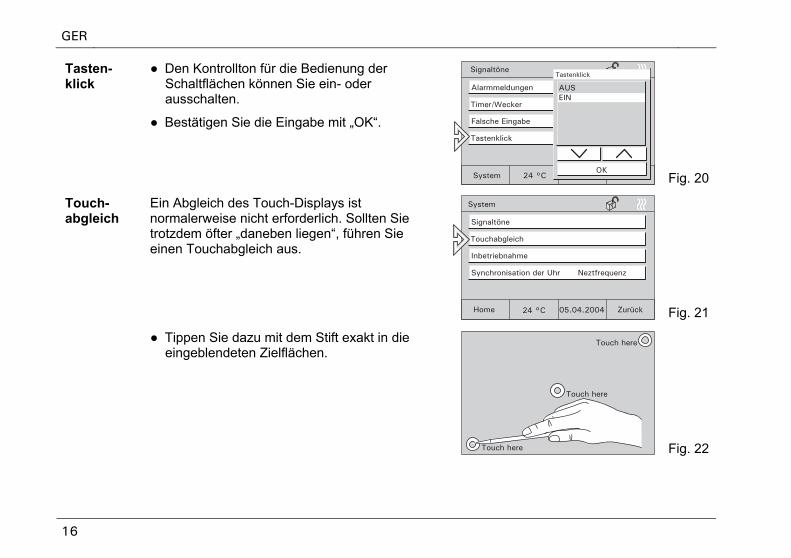
Tasten-klick
● Den Kontrollton für die Bedienung der Schaltflächen können Sie ein- oder ausschalten.
● Bestätigen Sie die Eingabe mit „OK“.
Fig. 20
Touch-abgleich
Ein Abgleich des Touch-Displays ist normalerweise nicht erforderlich. Sollten Sie trotzdem öfter „daneben liegen“, führen Sie einen Touchabgleich aus.
Fig. 21
● Tippen Sie dazu mit dem Stift exakt in die eingeblendeten Zielflächen.
Fig. 22
GER
17
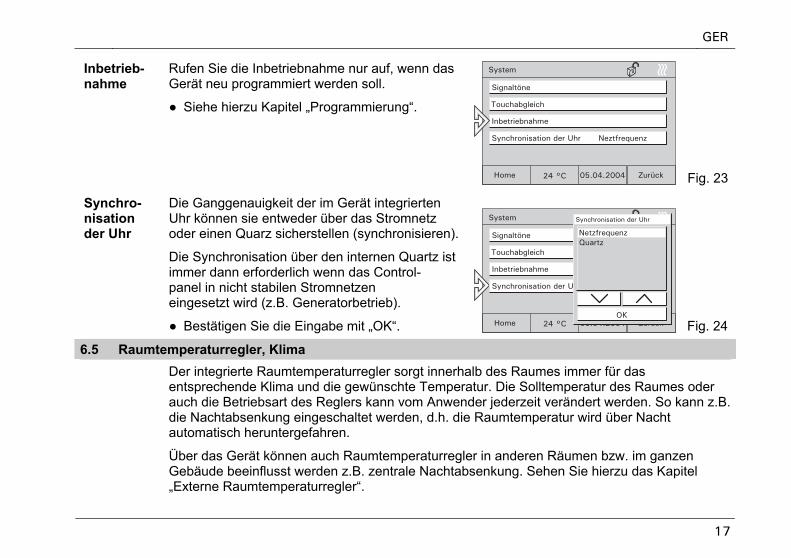
Inbetrieb-nahme
Rufen Sie die Inbetriebnahme nur auf, wenn das Gerät neu programmiert werden soll.
● Siehe hierzu Kapitel „Programmierung“.
Fig. 23
Synchro-nisation der Uhr
Die Ganggenauigkeit der im Gerät integrierten Uhr können sie entweder über das Stromnetz oder einen Quarz sicherstellen (synchronisieren).
Die Synchronisation über den internen Quartz ist immer dann erforderlich wenn das Control-panel in nicht stabilen Stromnetzen eingesetzt wird (z.B. Generatorbetrieb).
● Bestätigen Sie die Eingabe mit „OK“. Fig. 24
6.5 Raumtemperaturregler, Klima
Der integrierte Raumtemperaturregler sorgt innerhalb des Raumes immer für das entsprechende Klima und die gewünschte Temperatur. Die Solltemperatur des Raumes oder auch die Betriebsart des Reglers kann vom Anwender jederzeit verändert werden. So kann z.B. die Nachtabsenkung eingeschaltet werden, d.h. die Raumtemperatur wird über Nacht automatisch heruntergefahren.
Über das Gerät können auch Raumtemperaturregler in anderen Räumen bzw. im ganzen Gebäude beeinflusst werden z.B. zentrale Nachtabsenkung. Sehen Sie hierzu das Kapitel „Externe Raumtemperaturregler“.
GER
18
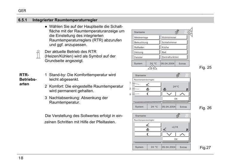
6.5.1 Integrierter Raumtemperaturregler
● Wählen Sie auf der Hauptseite die Schalt-fläche mit der Raumtemperaturanzeige um die Einstellung des integrierten Raumtemperaturreglers (RTR) abzurufen und ggf. anzupassen.
Der aktuelle Betrieb des RTR (Heizen/Kühlen) wird als Symbol auf der Grundseite angezeigt.
Fig. 25
RTR-Betriebs-arten
1 Stand-by: Die Komforttemperatur wird leicht abgesenkt.
2 Komfort: Die eingestellte Raumtemperatur wird permanent gehalten.
3 Nachtabsenkung: Absenkung der Raumtemperatur.
+2,7 K
Fig. 26
Die Verstellung des Sollwertes erfolgt in ein-
zelnen Schritten mit Hilfe der Pfeiltasten.
Fig.27
GER
19
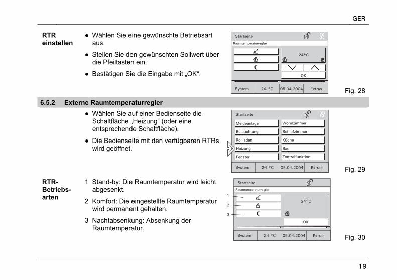
RTR einstellen
● Wählen Sie eine gewünschte Betriebsart aus.
● Stellen Sie den gewünschten Sollwert über die Pfeiltasten ein.
● Bestätigen Sie die Eingabe mit „OK“.
Fig. 28
6.5.2 Externe Raumtemperaturregler ● Wählen Sie auf einer Bedienseite die
Schaltfläche „Heizung“ (oder eine entsprechende Schaltfläche).
● Die Bedienseite mit den verfügbaren RTRs wird geöffnet.
Fig. 29
RTR-Betriebs-arten
1 Stand-by: Die Raumtemperatur wird leicht abgesenkt.
2 Komfort: Die eingestellte Raumtemperatur wird permanent gehalten.
3 Nachtabsenkung: Absenkung der Raumtemperatur.
Fig. 30
GER
20
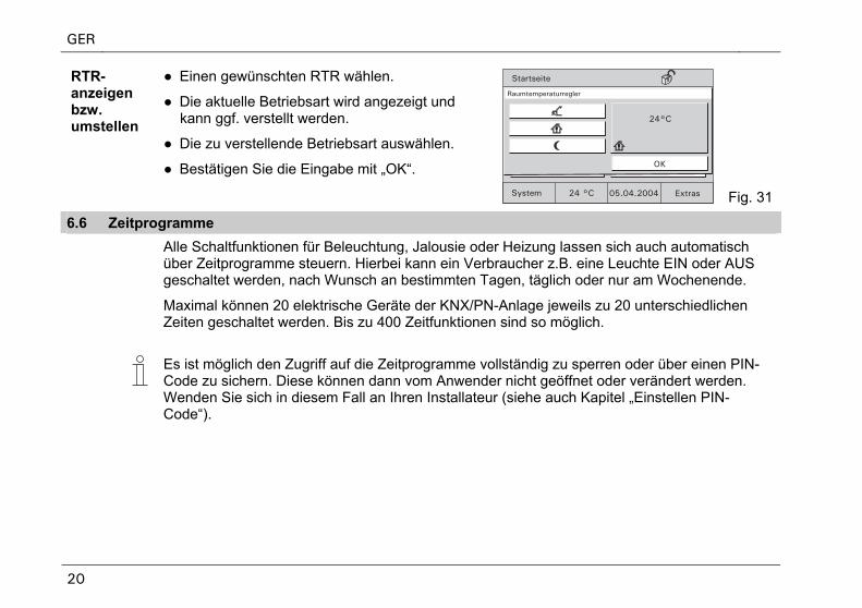
RTR- anzeigen bzw. umstellen
● Einen gewünschten RTR wählen.
● Die aktuelle Betriebsart wird angezeigt und kann ggf. verstellt werden.
● Die zu verstellende Betriebsart auswählen.
● Bestätigen Sie die Eingabe mit „OK“.
Fig. 31
6.6 Zeitprogramme
Alle Schaltfunktionen für Beleuchtung, Jalousie oder Heizung lassen sich auch automatisch über Zeitprogramme steuern. Hierbei kann ein Verbraucher z.B. eine Leuchte EIN oder AUS geschaltet werden, nach Wunsch an bestimmten Tagen, täglich oder nur am Wochenende.
Maximal können 20 elektrische Geräte der KNX/PN-Anlage jeweils zu 20 unterschiedlichenZeiten geschaltet werden. Bis zu 400 Zeitfunktionen sind so möglich.
Es ist möglich den Zugriff auf die Zeitprogramme vollständig zu sperren oder über einen PIN-Code zu sichern. Diese können dann vom Anwender nicht geöffnet oder verändert werden. Wenden Sie sich in diesem Fall an Ihren Installateur (siehe auch Kapitel „Einstellen PIN-Code“).
GER
21
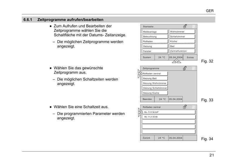
6.6.1 Zeitprogramme aufrufen/bearbeiten ● Zum Aufrufen und Bearbeiten der
Zeitprogramme wählen Sie die Schaltfläche mit der Datums- Zeitanzeige.
– Die möglichen Zeitprogramme werden angezeigt.
Fig. 32
● Wählen Sie das gewünschte Zeitprogramm aus.
– Die möglichen Schaltzeiten werden angezeigt.
Fig. 33
● Wählen Sie eine Schaltzeit aus.
– Die programmierten Parameter werden angezeigt.
Mo - Fr 07:00 AUF
Mo - Fr 21:30 AB
Fig. 34
GER
22
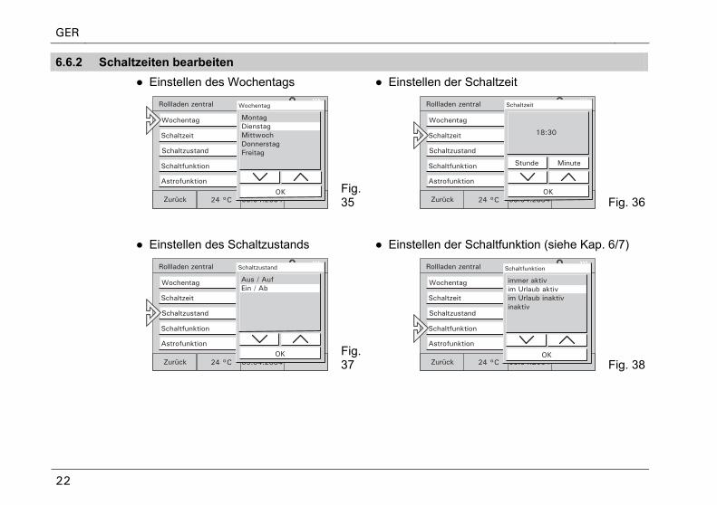
6.6.2 Schaltzeiten bearbeiten ● Einstellen des Wochentags ● Einstellen der Schaltzeit
Fig. 35 Fig. 36
● Einstellen des Schaltzustands ● Einstellen der Schaltfunktion (siehe Kap. 6/7)
Fig. 37 Fig. 38
GER
23
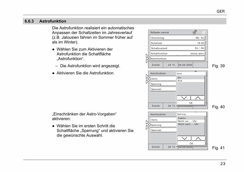
6.6.3 Astrofunktion Die Astrofunktion realisiert ein automatisches
Anpassen der Schaltzeiten im Jahresverlauf (z.B. Jalousien fahren im Sommer früher auf als im Winter).
● Wählen Sie zum Aktivieren der Astrofunktion die Schaltfläche „Astrofunktion“.
– Die Astrofunktion wird angezeigt. Fig. 39
● Aktivieren Sie die Astrofunktion.
Fig. 401
„Einschränken der Astro-Vorgaben“ aktivieren:
● Wählen Sie im ersten Schritt die Schaltfläche „Sperrung“ und aktivieren Sie die gewünschte Auswahl.
Fig. 41
GER
24
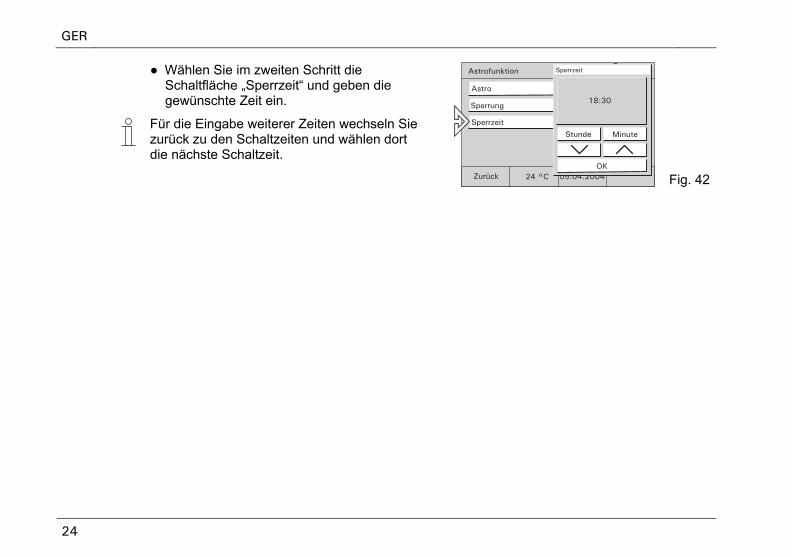
● Wählen Sie im zweiten Schritt die Schaltfläche „Sperrzeit“ und geben die gewünschte Zeit ein.
Für die Eingabe weiterer Zeiten wechseln Sie zurück zu den Schaltzeiten und wählen dort die nächste Schaltzeit.
Fig. 42
GER
25
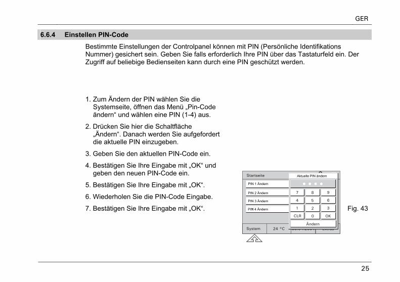
6.6.4 Einstellen PIN-Code
Bestimmte Einstellungen der Controlpanel können mit PIN (Persönliche Identifikations Nummer) gesichert sein. Geben Sie falls erforderlich Ihre PIN über das Tastaturfeld ein. Der Zugriff auf beliebige Bedienseiten kann durch eine PIN geschützt werden.
1. Zum Ändern der PIN wählen Sie die Systemseite, öffnen das Menü „Pin-Codeändern“ und wählen eine PIN (1-4) aus.
2. Drücken Sie hier die Schaltfläche „Ändern“. Danach werden Sie aufgefordert die aktuelle PIN einzugeben.
3. Geben Sie den aktuellen PIN-Code ein.
4. Bestätigen Sie Ihre Eingabe mit „OK“ und geben den neuen PIN-Code ein.
5. Bestätigen Sie Ihre Eingabe mit „OK“.
6. Wiederholen Sie die PIN-Code Eingabe.
7. Bestätigen Sie Ihre Eingabe mit „OK“.
Aktuelle PIN ändern
PIN 1 Ändern
PIN 2 Ändern
PIN 3 Ändern
PIN 4 Ändern Fig. 43
GER
26
6.7 Urlaub und Anwesenheitssimulation
Urlaubs-funktion
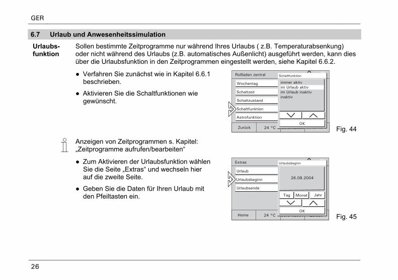
Sollen bestimmte Zeitprogramme nur während Ihres Urlaubs ( z.B. Temperaturabsenkung) oder nicht während des Urlaubs (z.B. automatisches Außenlicht) ausgeführt werden, kann dies über die Urlaubsfunktion in den Zeitprogrammen eingestellt werden, siehe Kapitel 6.6.2.
● Verfahren Sie zunächst wie in Kapitel 6.6.1 beschrieben.
● Aktivieren Sie die Schaltfunktionen wie gewünscht.
Fig. 44
Anzeigen von Zeitprogrammen s. Kapitel: „Zeitprogramme aufrufen/bearbeiten“
● Zum Aktivieren der Urlaubsfunktion wählen Sie die Seite „Extras“ und wechseln hier auf die zweite Seite.
● Geben Sie die Daten für Ihren Urlaub mit den Pfeiltasten ein.
Fig. 45
GER
27
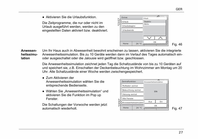
● Aktivieren Sie die Urlaubsfunktion.
Die Zeitprogramme, die nur oder nicht im Urlaub ausgeführt werden, werden zu den eingestellten Daten aktiviert bzw. deaktiviert.
Fig. 46
Anwesen-heitssimu-lation
Um Ihr Haus auch in Abwesenheit bewohnt erscheinen zu lassen, aktivieren Sie die integrierte Anwesenheitssimulation. Bis zu 10 Geräte werden dann im Verlauf des Tages automatisch ein- oder ausgeschaltet oder die Jalousie wird geöffnet bzw. geschlossen.
Die Anwesenheitssimulation zeichnet jeden Tag die Schaltzustände von bis zu 10 Geräten auf und speichert sie, z.B. Einschalten der Deckenbeleuchtung im Wohnzimmer am Montag um 20 Uhr. Alle Schaltzustände einer Woche werden zwischengespeichert.
● Zum Aktivieren der Anwesenheitssimulation wählen Sie die entsprechende Bedienseite.
● Wählen Sie „Anwesenheitssimulation“ und aktivieren Sie die Funktion im Pop up Fenster.
Die Schaltungen der Vorwoche werden jetzt automatisch wiederholt. Fig. 47
GER
28
6.8 Licht und Lichtszenen Durch die individuelle und flexible Belegung der Touch-Bedienflächen lassen sich alle, in die KNX
- oder Powernetanlage eingebundenen elektrischen Geräte, insbesondere Leuchten, schalten. Die jeweiligen Schaltzustände werden im Display entweder im Klartext oder in Form von Symbolen (z.B. in Form einer Glühlampe) visualisiert.
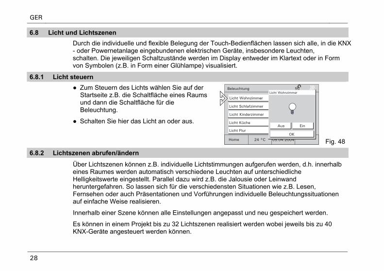
6.8.1 Licht steuern ● Zum Steuern des Lichts wählen Sie auf der
Startseite z.B. die Schaltfläche eines Raums und dann die Schaltfläche für die Beleuchtung.
● Schalten Sie hier das Licht an oder aus.
Fig. 48
6.8.2 Lichtszenen abrufen/ändern
Über Lichtszenen können z.B. individuelle Lichtstimmungen aufgerufen werden, d.h. innerhalb eines Raumes werden automatisch verschiedene Leuchten auf unterschiedliche Helligkeitswerte eingestellt. Parallel dazu wird z.B. die Jalousie oder Leinwand heruntergefahren. So lassen sich für die verschiedensten Situationen wie z.B. Lesen, Fernsehen oder auch Präsentationen und Vorführungen individuelle Beleuchtungssituationen auf einfache Weise realisieren.
Innerhalb einer Szene können alle Einstellungen angepasst und neu gespeichert werden.
Es können in einem Projekt bis zu 32 Lichtszenen realisiert werden wobei jeweils bis zu 40 KNX-Geräte angesteuert werden können.
GER
29
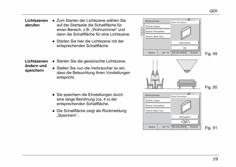
Lichtszenen abrufen
● Zum Starten der Lichtszene wählen Sie auf der Startseite die Schaltfläche für einen Bereich, z.B. „Wohnzimmer“ und dann die Schaltfläche für eine Lichtszene.
● Starten Sie hier die Lichtszene mit der entsprechenden Schaltfläche.
Fig. 49
Lichtszenen ändern und speichern
● Starten Sie die gewünschte Lichtszene.
● Stellen Sie nun die Verbraucher so ein, dass die Beleuchtung Ihren Vorstellungen entspricht.
Fig. 50
● Sie speichern die Einstellungen durch eine lange Berührung (ca. 4 s) der entsprechenden Schaltfläche.
● Die Schaltfläche zeigt als Rückmeldung „Speichern“.
Fig. 51
GER
30
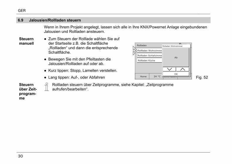
6.9 Jalousien/Rollladen steuern
Wenn in Ihrem Projekt angelegt, lassen sich alle in Ihre KNX/Powernet Anlage eingebundenen Jalousien und Rollladen ansteuern.
Steuern manuell
● Zum Steuern der Rolllade wählen Sie auf der Startseite z.B. die Schaltfläche „Rollladen“ und dann die entsprechende Schaltfläche.
● Bewegen Sie mit den Pfeiltasten die Jalousien/Rollladen auf oder ab.
● Kurz tippen: Stopp, Lamellen verstellen.
● Lang tippen: Auf-, oder Abfahren Fig. 52
Steuern über Zeit-program-me
Rollladen steuern über Zeitprogramme, siehe Kapitel: „Zeitprogramme aufrufen/bearbeiten“.
GER
31
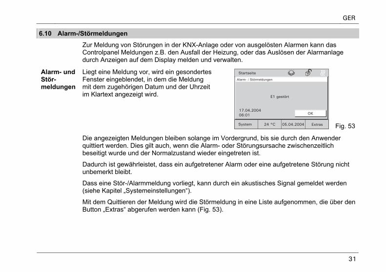
6.10 Alarm-/Störmeldungen
Zur Meldung von Störungen in der KNX-Anlage oder von ausgelösten Alarmen kann dasControlpanel Meldungen z.B. den Ausfall der Heizung, oder das Auslösen der Alarmanlage durch Anzeigen auf dem Display melden und verwalten.
Alarm- und Stör-meldungen
Liegt eine Meldung vor, wird ein gesondertes Fenster eingeblendet, in dem die Meldung mit dem zugehörigen Datum und der Uhrzeit im Klartext angezeigt wird.
Fig. 53
Die angezeigten Meldungen bleiben solange im Vordergrund, bis sie durch den Anwender quittiert werden. Dies gilt auch, wenn die Alarm- oder Störungsursache zwischenzeitlich beseitigt wurde und der Normalzustand wieder eingetreten ist.
Dadurch ist gewährleistet, dass ein aufgetretener Alarm oder eine aufgetretene Störung nicht unbemerkt bleibt.
Dass eine Stör-/Alarmmeldung vorliegt, kann durch ein akustisches Signal gemeldet werden (siehe Kapitel „Systemeinstellungen“).
Mit dem Quittieren der Meldung wird die Störmeldung in eine Liste aufgenommen, die über den Button „Extras“ abgerufen werden kann (Fig. 53).
GER
32
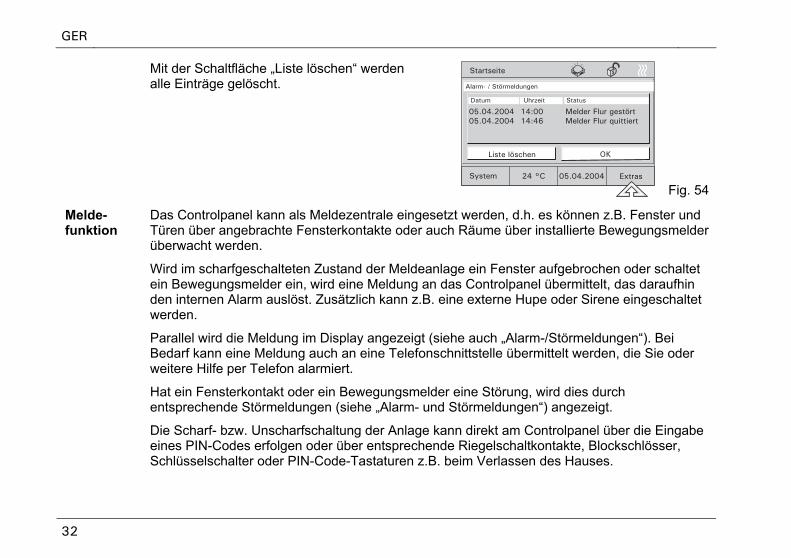
Mit der Schaltfläche „Liste löschen“ werden alle Einträge gelöscht.
Fig. 54
Melde-funktion (nur beim C
Das Controlpanel kann als Meldezentrale eingesetzt werden, d.h. es können z.B. Fenster und Türen über angebrachte Fensterkontakte oder auch Räume über installierte Bewegungsmelder überwacht werden.
Wird im scharfgeschalteten Zustand der Meldeanlage ein Fenster aufgebrochen oder schaltet ein Bewegungsmelder ein, wird eine Meldung an das Controlpanel übermittelt, das daraufhin den internen Alarm auslöst. Zusätzlich kann z.B. eine externe Hupe oder Sirene eingeschaltet werden.
Parallel wird die Meldung im Display angezeigt (siehe auch „Alarm-/Störmeldungen“). Bei Bedarf kann eine Meldung auch an eine Telefonschnittstelle übermittelt werden, die Sie oder weitere Hilfe per Telefon alarmiert.
Hat ein Fensterkontakt oder ein Bewegungsmelder eine Störung, wird dies durch entsprechende Störmeldungen (siehe „Alarm- und Störmeldungen“) angezeigt.
Die Scharf- bzw. Unscharfschaltung der Anlage kann direkt am Controlpanel über die Eingabe eines PIN-Codes erfolgen oder über entsprechende Riegelschaltkontakte, Blockschlösser, Schlüsselschalter oder PIN-Code-Tastaturen z.B. beim Verlassen des Hauses.
GER
33
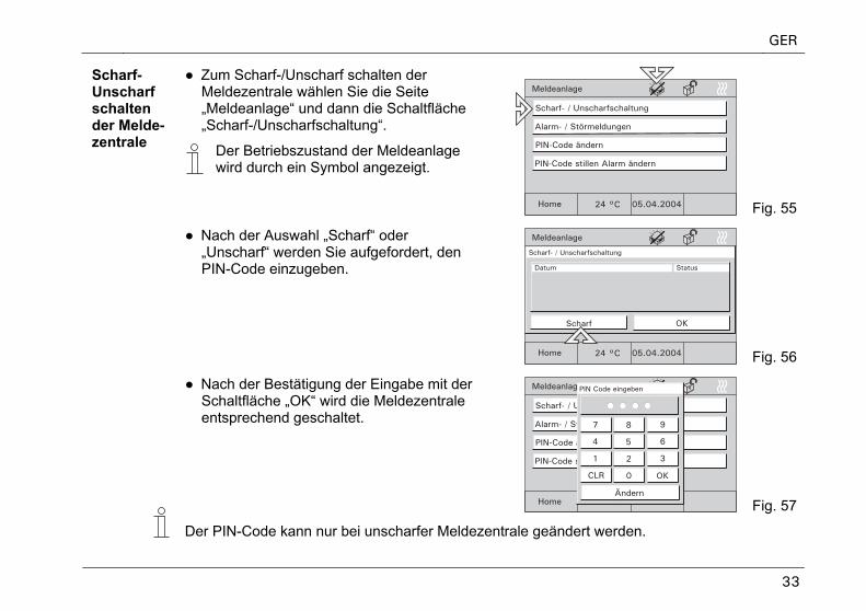
● Zum Scharf-/Unscharf schalten der Meldezentrale wählen Sie die Seite „Meldeanlage“ und dann die Schaltfläche „Scharf-/Unscharfschaltung“.
Scharf-Unscharf schalten der Melde-zentrale
Der Betriebszustand der Meldeanlage wird durch ein Symbol angezeigt.
Fig. 55
● Nach der Auswahl „Scharf“ oder „Unscharf“ werden Sie aufgefordert, den PIN-Code einzugeben.
Meldeanlage
Home 05.04.2004
Scharf- / Unscharfschaltung
Alarm- / Störmeldungen
24 °C
PIN-Code ändern
PIN-Code stillen Alarm ändern
Scharf- / Unscharfschaltung
OKScharf
Datum Status
Fig. 56
● Nach der Bestätigung der Eingabe mit der Schaltfläche „OK“ wird die Meldezentrale entsprechend geschaltet.
Fig. 57
Der PIN-Code kann nur bei unscharfer Meldezentrale geändert werden.
GER
34
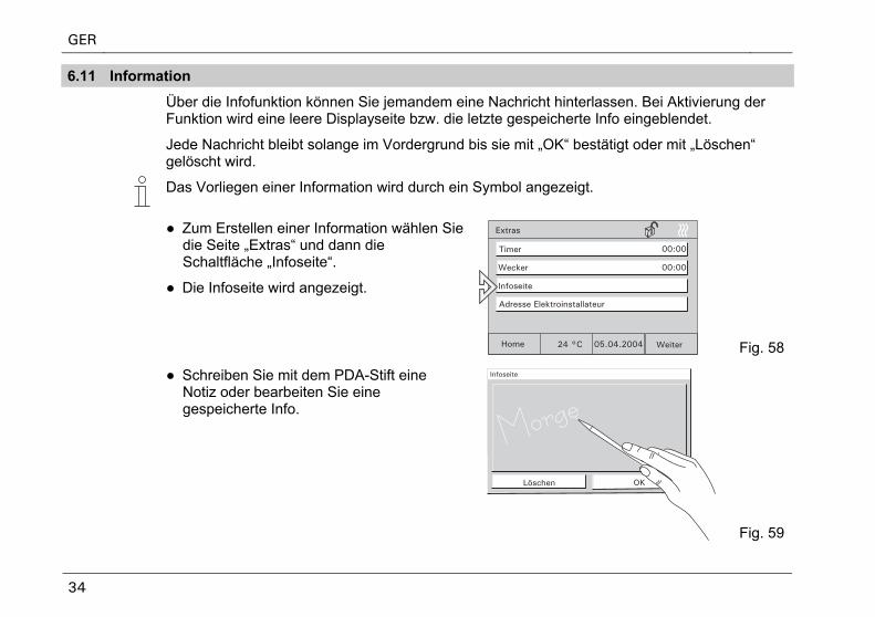
6.11 Information
Über die Infofunktion können Sie jemandem eine Nachricht hinterlassen. Bei Aktivierung der Funktion wird eine leere Displayseite bzw. die letzte gespeicherte Info eingeblendet.
Jede Nachricht bleibt solange im Vordergrund bis sie mit „OK“ bestätigt oder mit „Löschen“ gelöscht wird.
Das Vorliegen einer Information wird durch ein Symbol angezeigt.
● Zum Erstellen einer Information wählen Sie die Seite „Extras“ und dann die Schaltfläche „Infoseite“.
● Die Infoseite wird angezeigt.
Fig. 58
● Schreiben Sie mit dem PDA-Stift eine Notiz oder bearbeiten Sie eine gespeicherte Info.
Fig. 59
GER
35
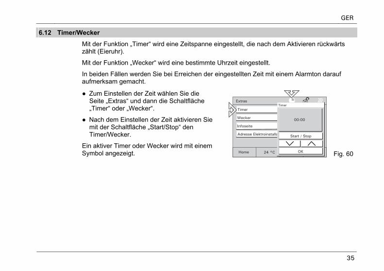
6.12 Timer/Wecker
Mit der Funktion „Timer“ wird eine Zeitspanne eingestellt, die nach dem Aktivieren rückwärts zählt (Eieruhr).
Mit der Funktion „Wecker“ wird eine bestimmte Uhrzeit eingestellt.
In beiden Fällen werden Sie bei Erreichen der eingestellten Zeit mit einem Alarmton darauf aufmerksam gemacht.
● Zum Einstellen der Zeit wählen Sie die Seite „Extras“ und dann die Schaltfläche „Timer“ oder „Wecker“.
● Nach dem Einstellen der Zeit aktivieren Sie mit der Schaltfläche „Start/Stop“ den Timer/Wecker.
Ein aktiver Timer oder Wecker wird mit einem Symbol angezeigt. Fig. 60
GER
36
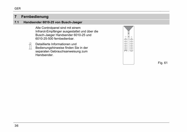
7 Fernbedienung
7.1 Handsender 6010-25 von Busch-Jaeger
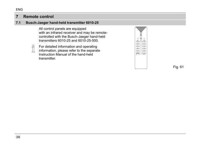
Alle Controlpanel sind mit einem Infrarot-Empfänger ausgestattet und über die Busch-Jaeger Handsender 6010-25 und 6010-25-500 fernbedienbar.
Detaillierte Informationen und Bedienungshinweise finden Sie in der separaten Gebrauchsanweisung zum Handsender.
Fig. 61
GER
37
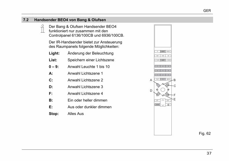
7.2 Handsender BEO4 von Bang & Olufsen
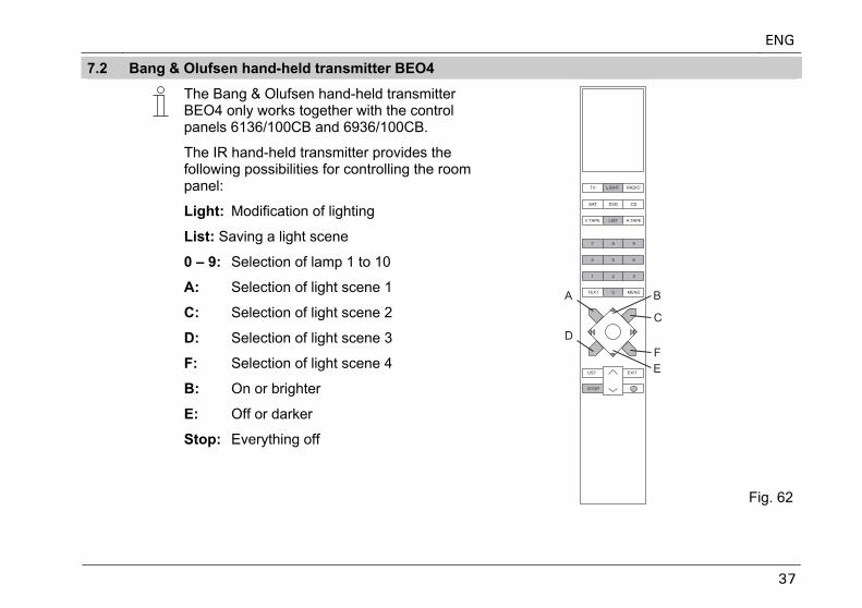
Der Bang & Olufsen Handsender BEO4 funktioniert nur zusammen mit den Controlpanel 6136/100CB und 6936/100CB.
Der IR-Handsender bietet zur Ansteuerung des Raumpanels folgende Möglichkeiten:
Light: Änderung der Beleuchtung
List: Speichern einer Lichtszene
0 – 9: Anwahl Leuchte 1 bis 10
A: Anwahl Lichtszene 1
C: Anwahl Lichtszene 2
D: Anwahl Lichtszene 3
F: Anwahl Lichtszene 4
B: Ein oder heller dimmen
E: Aus oder dunkler dimmen
Stop: Alles Aus
Fig. 62
GER
38
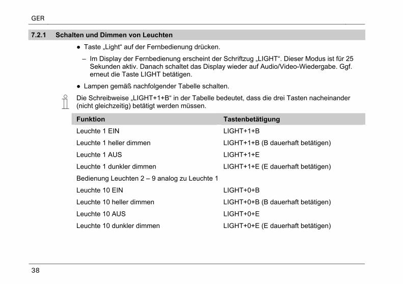
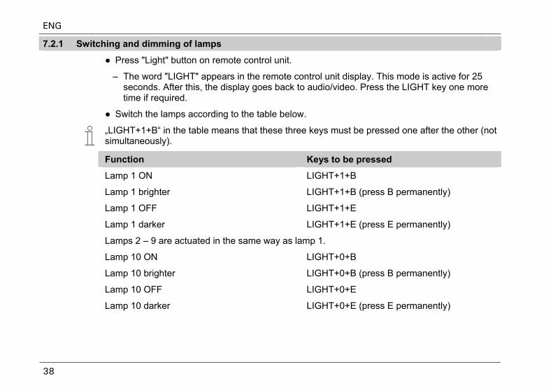
7.2.1 Schalten und Dimmen von Leuchten
● Taste „Light“ auf der Fernbedienung drücken.
– Im Display der Fernbedienung erscheint der Schriftzug „LIGHT“. Dieser Modus ist für 25 Sekunden aktiv. Danach schaltet das Display wieder auf Audio/Video-Wiedergabe. Ggf. erneut die Taste LIGHT betätigen.
● Lampen gemäß nachfolgender Tabelle schalten.
Die Schreibweise „LIGHT+1+B“ in der Tabelle bedeutet, dass die drei Tasten nacheinander (nicht gleichzeitig) betätigt werden müssen.
Funktion Tastenbetätigung
Leuchte 1 EIN LIGHT+1+B
Leuchte 1 heller dimmen LIGHT+1+B (B dauerhaft betätigen)
Leuchte 1 AUS LIGHT+1+E
Leuchte 1 dunkler dimmen LIGHT+1+E (E dauerhaft betätigen)
Bedienung Leuchten 2 – 9 analog zu Leuchte 1
Leuchte 10 EIN LIGHT+0+B
Leuchte 10 heller dimmen LIGHT+0+B (B dauerhaft betätigen)
Leuchte 10 AUS LIGHT+0+E
Leuchte 10 dunkler dimmen LIGHT+0+E (E dauerhaft betätigen)
GER
39
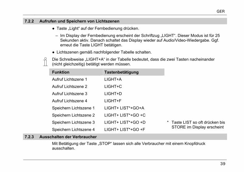
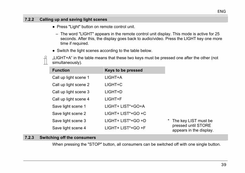
7.2.2 Aufrufen und Speichern von Lichtszenen
● Taste „Light“ auf der Fernbedienung drücken.
– Im Display der Fernbedienung erscheint der Schriftzug „LIGHT“. Dieser Modus ist für 25 Sekunden aktiv. Danach schaltet das Display wieder auf Audio/Video-Wiedergabe. Ggf. erneut die Taste LIGHT betätigen.
● Lichtszenen gemäß nachfolgender Tabelle schalten.
Die Schreibweise „LIGHT+A“ in der Tabelle bedeutet, dass die zwei Tasten nacheinander (nicht gleichzeitig) betätigt werden müssen.
Funktion Tastenbetätigung
Aufruf Lichtszene 1 LIGHT+A
Aufruf Lichtszene 2 LIGHT+C
Aufruf Lichtszene 3 LIGHT+D
Aufruf Lichtszene 4 LIGHT+F
Speichern Lichtszene 1 LIGHT+ LIST*+GO+A
Speichern Lichtszene 2 LIGHT+ LIST*+GO +C
Speichern Lichtszene 3 LIGHT+ LIST*+GO +D
Speichern Lichtszene 4 LIGHT+ LIST*+GO +F
* Taste LIST so oft drücken bis STORE im Display erscheint
7.2.3 Ausschalten der Verbraucher Mit Betätigung der Taste „STOP“ lassen sich alle Verbraucher mit einem Knopfdruck
ausschalten.
GER
40
8 Installation
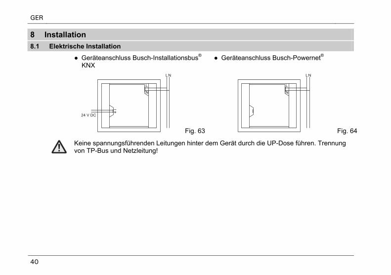
8.1 Elektrische Installation
● Geräteanschluss Busch-Installationsbus® KNX
● Geräteanschluss Busch-Powernet®
Fig. 63 Fig. 64
Keine spannungsführenden Leitungen hinter dem Gerät durch die UP-Dose führen. Trennung von TP-Bus und Netzleitung!
GER
41
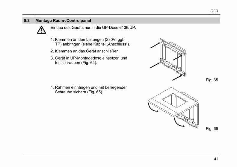
8.2 Montage Raum-/Controlpanel
Einbau des Geräts nur in die UP-Dose 6136/UP.
1. Klemmen an den Leitungen (230V, ggf. TP) anbringen (siehe Kapitel „Anschluss“).
2. Klemmen an das Gerät anschließen.
3. Gerät in UP-Montagedose einsetzen und festschrauben (Fig. 64).
Fig. 65
4. Rahmen einhängen und mit beiliegender Schraube sichern (Fig. 65).
Fig. 66
GER
42
9 Software
9.1 Installation
ETS 2
(ab V. 1.3)
1. Panel-Inbetriebnahmesoftware aus der aktuellen KNX-Datenbank auf einem PC installieren.
2. Produktdatenbank in die ETS importieren.
3. Gerät parametrieren/konfigurieren.
Power-Projekt >4.5
1. Panel-Inbetriebnahmesoftware aus der aktuellen KNX-Datenbank oder von der Power-Projekt-CD installieren.
2. Gerät parametrieren/konfigurieren (siehe oben).
Die KNX Datenbank können Sie über Busch-Jaeger direkt beziehen oder im Internet unter www.BUSCH-JAEGER.de downloaden.
GER
43
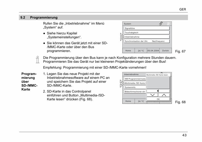
9.2 Programmierung
Rufen Sie die „Inbetriebnahme“ im Menü „System“ auf.
● Siehe hierzu Kapitel „Systemeinstellungen“.
● Sie können das Gerät jetzt mit einer SD-/MMC-Karte oder über den Bus programmieren. Fig. 67
Die Programmierung über den Bus kann je nach Konfiguration mehrere Stunden dauern. Programmieren Sie das Gerät nur bei kleineren Projektänderungen über den Bus!
Empfehlung: Programmierung mit einer SD-/MMC-Karte vornehmen!
Program-mierung über SD-/MMC-Karte
1. Legen Sie das neue Projekt mit der Inbetriebnahmesoftware auf einem PC an und speichern Sie das Projekt auf einer SD-/MMC-Karte.
2. SD-Karte in das Controlpanel einführen und Button „Multimedia-/SD-Karte lesen“ drücken (Fig. 68).
Fig. 68
GER
44
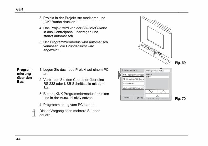
3. Projekt in der Projektliste markieren und „OK“ Button drücken.
4. Das Projekt wird von der SD-/MMC-Karte in das Controlpanel übertragen und startet automatisch.
5. Der Programmiermodus wird automatisch verlassen, die Grundansicht wird angezeigt.
Fig. 69
Program-mierung über den Bus
1. Legen Sie das neue Projekt auf einem PC an.
2. Verbinden Sie den Computer über eine RS 232 oder USB Schnittstelle mit dem Bus.
3: Button „KNX Programmiermodus“ drücken und in der Auswahl aktiv setzen.
KNX
Fig. 70
4. Programmierung vom PC starten.
Dieser Vorgang kann mehrere Stunden dauern.
GER
45
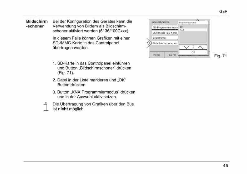
Bildschirm-schoner
Bei der Konfiguration des Gerätes kann die Verwendung von Bildern als Bildschirm-schoner aktiviert werden (6136/100Cxxx).
In diesem Falle können Grafiken mit einer SD-/MMC-Karte in das Controlpanel übertragen werden.
Fig. 71
1. SD-Karte in das Controlpanel einführen und Button „Bildschirmschoner“ drücken (Fig. 71).
2. Datei in der Liste markieren und „OK“ Button drücken.
3. Button „KNX Programmiermodus“ drücken und in der Auswahl aktiv setzen.
Die Übertragung von Grafiken über den Bus ist nicht möglich.
GER
46
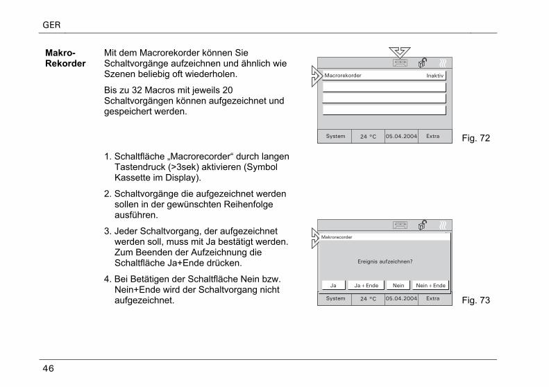
Makro-Rekorder
Mit dem Macrorekorder können Sie Schaltvorgänge aufzeichnen und ähnlich wie Szenen beliebig oft wiederholen.
Bis zu 32 Macros mit jeweils 20 Schaltvorgängen können aufgezeichnet und gespeichert werden.
Fig. 72
1. Schaltfläche „Macrorecorder“ durch langen Tastendruck (>3sek) aktivieren (Symbol Kassette im Display).
2. Schaltvorgänge die aufgezeichnet werden sollen in der gewünschten Reihenfolge ausführen.
3. Jeder Schaltvorgang, der aufgezeichnet werden soll, muss mit Ja bestätigt werden. Zum Beenden der Aufzeichnung die Schaltfläche Ja+Ende drücken.
4. Bei Betätigen der Schaltfläche Nein bzw. Nein+Ende wird der Schaltvorgang nicht aufgezeichnet. Fig. 73
GER
47
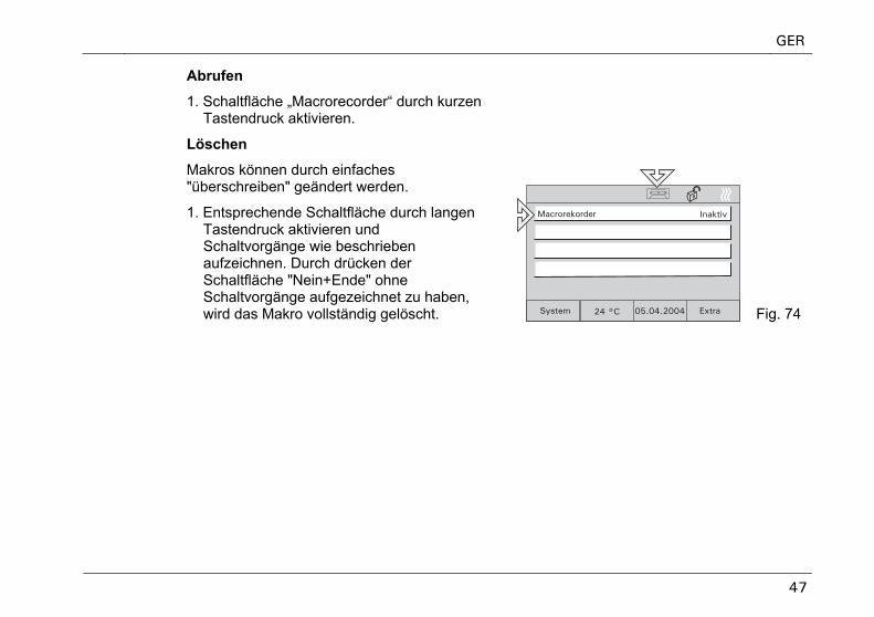
Abrufen
1. Schaltfläche „Macrorecorder“ durch kurzen Tastendruck aktivieren.
Löschen
Makros können durch einfaches "überschreiben" geändert werden.
1. Entsprechende Schaltfläche durch langen Tastendruck aktivieren und Schaltvorgänge wie beschrieben aufzeichnen. Durch drücken der Schaltfläche "Nein+Ende" ohne Schaltvorgänge aufgezeichnet zu haben, wird das Makro vollständig gelöscht. Fig. 74
Controlpanel 6136/100C-102 6936/100C-102 Controlpanel 6136/100CB-102
6936/100CB-102
ENG Operating Instructions

ENG
3
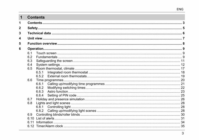
1 Contents 1 Contents....................................................................................................................................................... 3 2 Safety............................................................................................................................................................ 5 3 Technical data ............................................................................................................................................. 6 4 Unit view....................................................................................................................................................... 7 5 Function overview....................................................................................................................................... 8 6 Operation...................................................................................................................................................... 9
6.1 Touch screen ....................................................................................................................................... 9 6.2 Fundamentals ...................................................................................................................................... 9 6.3 Safeguarding the screen.................................................................................................................... 11 6.4 System settings.................................................................................................................................. 12 6.5 Room thermostat, climate .................................................................................................................. 17
6.5.1 Integrated room thermostat ................................................................................................... 18 6.5.2 External room thermostats..................................................................................................... 19
6.6 Time programmes.............................................................................................................................. 20 6.6.1 Calling up/modifying time programmes ................................................................................. 21 6.6.2 Modifying switching times ...................................................................................................... 22 6.6.3 Astro function......................................................................................................................... 23 6.6.4 Setting of PIN code................................................................................................................ 25
6.7 Holiday and presence simulation ....................................................................................................... 26 6.8 Lights and light scenes ...................................................................................................................... 28
6.8.1 Controlling light ...................................................................................................................... 28 6.8.2 Calling up/modifying light scenes .......................................................................................... 28
6.9 Controlling blinds/roller blinds ............................................................................................................ 30 6.10 List of alerts........................................................................................................................................ 31 6.11 Information ......................................................................................................................................... 34 6.12 Timer/Alarm clock .............................................................................................................................. 35
ENG
4
7 Remote control .......................................................................................................................................... 36 7.1 Busch-Jaeger hand-held transmitter 6010-25.................................................................................... 36 7.2 Bang & Olufsen hand-held transmitter BEO4 .................................................................................... 37
7.2.1 Switching and dimming of lamps ........................................................................................... 38 7.2.2 Calling up and saving light scenes ........................................................................................ 39 7.2.3 Switching off the consumers.................................................................................................. 39
8 Installation.................................................................................................................................................. 40 8.1 Electric installation ............................................................................................................................. 40 8.2 Installation of room/control panel ....................................................................................................... 41
9 Software ..................................................................................................................................................... 42 9.1 Installation .......................................................................................................................................... 42 9.2 Programming...................................................................................................................................... 43
ENG
5
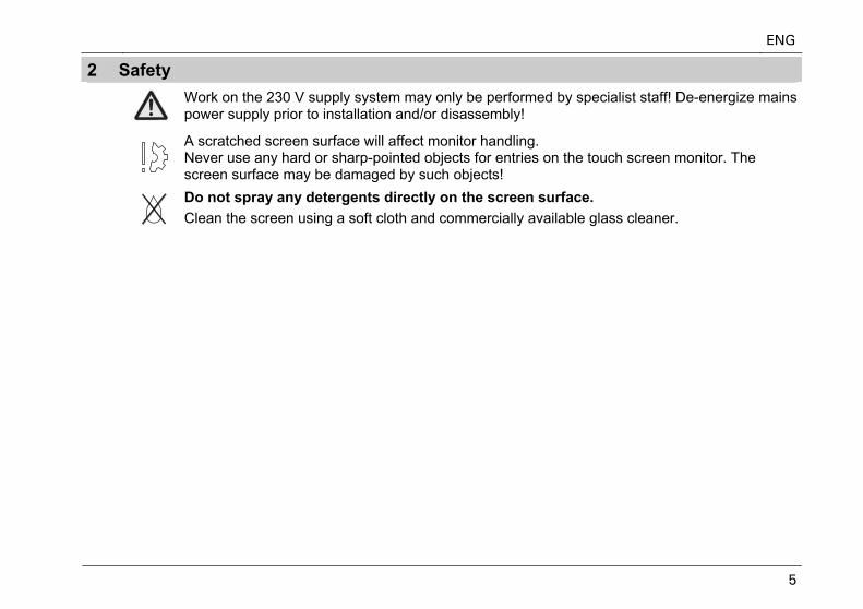
2 Safety
Work on the 230 V supply system may only be performed by specialist staff! De-energize mains power supply prior to installation and/or disassembly!
A scratched screen surface will affect monitor handling. Never use any hard or sharp-pointed objects for entries on the touch screen monitor. The screen surface may be damaged by such objects!
Do not spray any detergents directly on the screen surface. Clean the screen using a soft cloth and commercially available glass cleaner.
ENG
6
3 Technical data Rated voltage 230V ±10%, ~50 Hz/60 Hz
Power consumption < 20VA
Operating temperature 0°C to +45°C
Storage -20°C to +60°C
Bus connection (TP) Bus terminal block
Room thermostat measuring range 0°C to +40°C
Dimensions incl. frame (W x H x D) 218 mm x 185 mm x 67 mm
Flush-mounting box
Dimensions (W x H x D) 200 mm x 164 mm x 60 mm
ENG
7
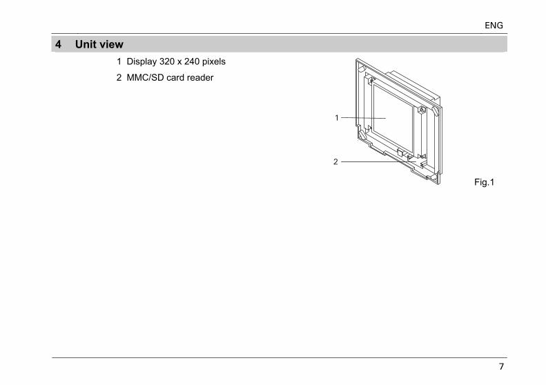
4 Unit view
1 Display 320 x 240 pixels
2 MMC/SD card reader
Fig.1
ENG
8
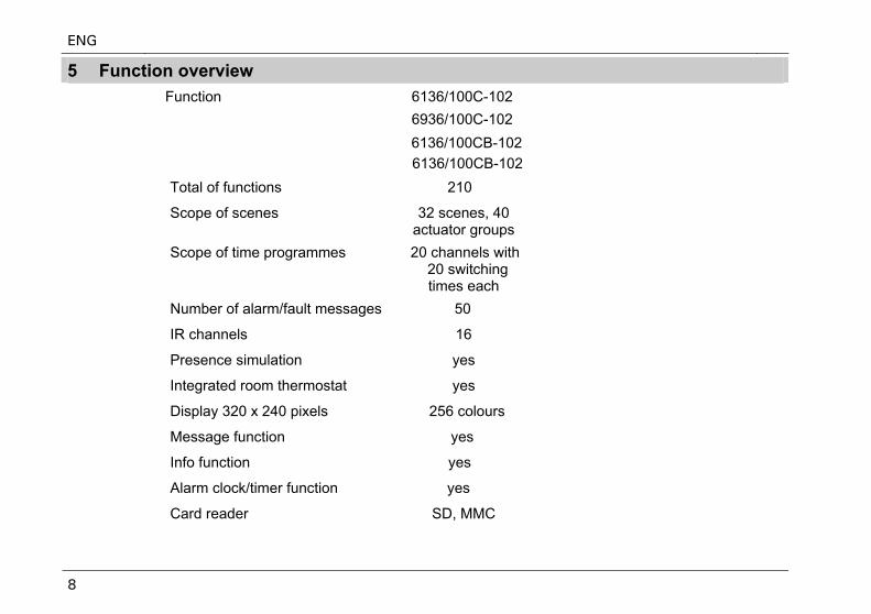
5 Function overview
Function 6136/100C-102 6936/100C-102
6136/100CB-101
Total of functions 210
Scope of scenes 32 scenes, 40 actuator groups
3 a
Scope of time programmes 20 channels with 20 switching times each
2 1
e
Number of alarm/fault messages 50
IR channels 16
Presence simulation yes
Integrated room thermostat yes
Display 320 x 240 pixels 256 colours
Message function yes
Info function yes
Alarm clock/timer function yes
Card reader SD, MMC
6136/100CB-1026136/100CB-102
ENG
9
6 Operation
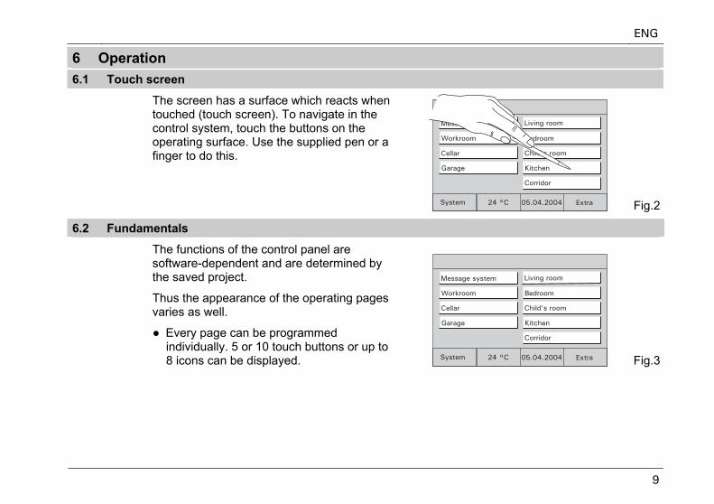
6.1 Touch screen
The screen has a surface which reacts when touched (touch screen). To navigate in the control system, touch the buttons on the operating surface. Use the supplied pen or a finger to do this.
Fig.2
6.2 Fundamentals
The functions of the control panel are software-dependent and are determined by the saved project.
Thus the appearance of the operating pages varies as well.
● Every page can be programmed individually. 5 or 10 touch buttons or up to 8 icons can be displayed. Fig.3
ENG
10
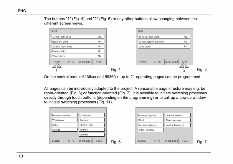
The buttons "1" (Fig. 4) and "2" (Fig. 5) or any other buttons allow changing between the different screen views.
Fig. 4 Fig. 5
On the control panels 6136/xx and 6936/xx, up to 21 operating pages can be programmed.
All pages can be individually adapted to the project. A reasonable page structure may e.g. be room-oriented (Fig. 6) or function-oriented (Fig. 7). It is possible to initiate switching processes directly through touch buttons (depending on the programming) or to call up a pop-up window to initiate switching processes (Fig. 11).
Fig. 6 Fig. 7
ENG
11
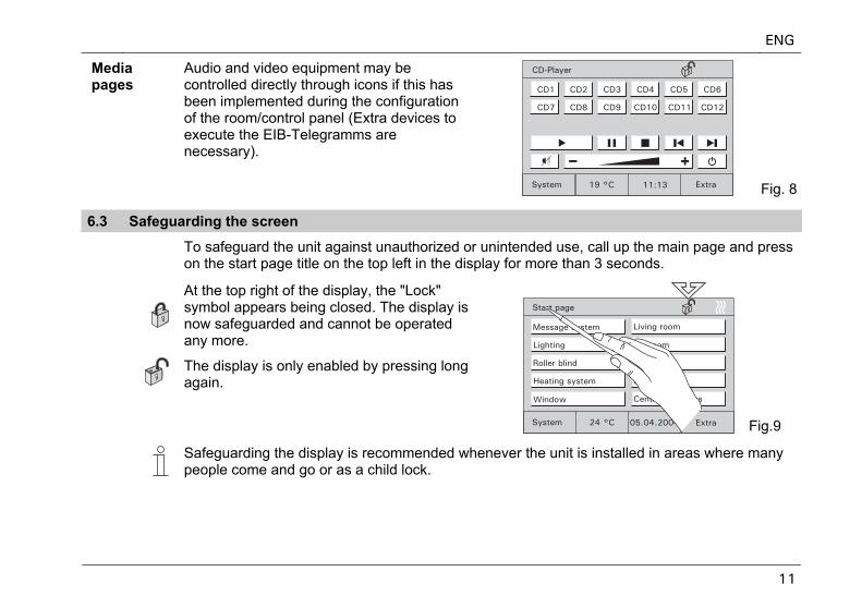
Media pages
Audio and video equipment may be controlled directly through icons if this has been implemented during the configuration of the room/control panel (Extra devices to execute the EIB-Telegramms are necessary).
Fig. 8
6.3 Safeguarding the screen
To safeguard the unit against unauthorized or unintended use, call up the main page and press on the start page title on the top left in the display for more than 3 seconds.
At the top right of the display, the "Lock" symbol appears being closed. The display is now safeguarded and cannot be operated any more.
The display is only enabled by pressing long again.
Fig.9
Safeguarding the display is recommended whenever the unit is installed in areas where many people come and go or as a child lock.
ENG
12
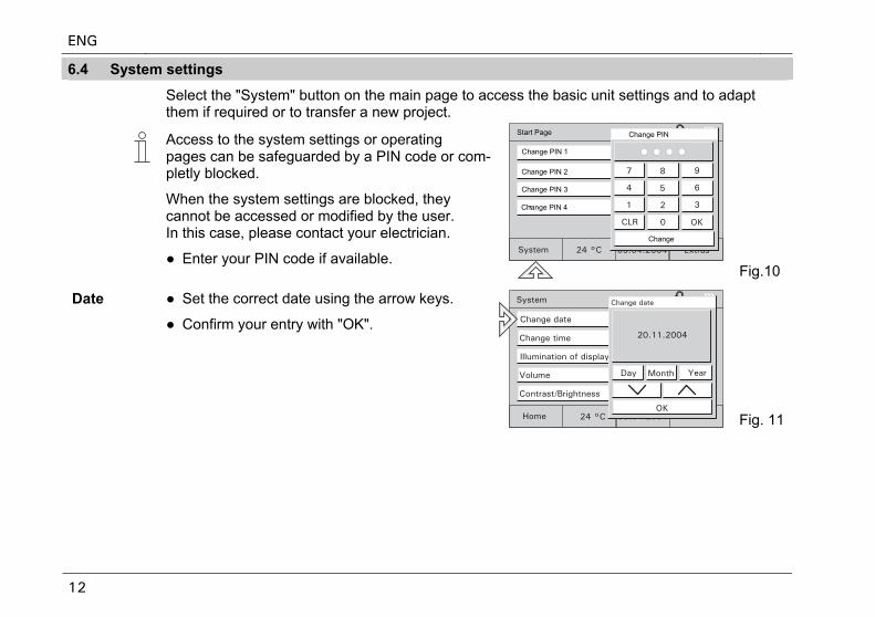
6.4 System settings
Select the "System" button on the main page to access the basic unit settings and to adapt them if required or to transfer a new project.
Access to the system settings or operating pages can be safeguarded by a PIN code or com- pletly blocked.
When the system settings are blocked, they cannot be accessed or modified by the user. In this case, please contact your electrician.
● Enter your PIN code if available. Fig.10
Date ● Set the correct date using the arrow keys.
● Confirm your entry with "OK".
Fig. 11
Change PIN
Change PIN 1
Change PIN 2
Change PIN 3
Change PIN 4
Change
Start Page
ENG
13
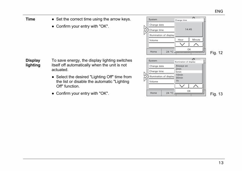
Time ● Set the correct time using the arrow keys.
● Confirm your entry with "OK".
Fig. 12
Display lighting
To save energy, the display lighting switches itself off automatically when the unit is not actuated.
● Select the desired "Lighting Off" time from the list or disable the automatic "Lighting Off" function.
● Confirm your entry with "OK". Fig. 13
ENG
14
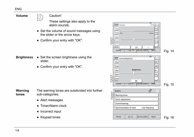
Caution!
These settings also apply to the alarm sounds.
Volume
● Set the volume of sound messages using the slider or the arrow keys.
● Confirm your entry with "OK".
Fig. 14
Brightness
● Set the screen brightness using the slider.
● Confirm your entry with "OK".
Fig. 15
Warning tones
The warning tones are subdivided into further sub-categories:
● Alert messages
● Timer/Alarm clock
● Incorrect input
● Keypad tones Fig. 16
ENG
15
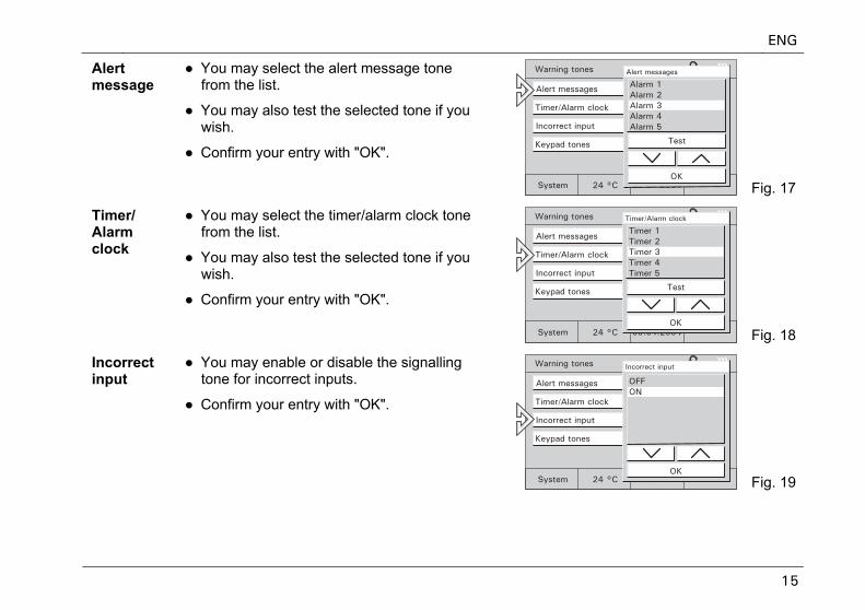
Alert message
● You may select the alert message tone from the list.
● You may also test the selected tone if you wish.
● Confirm your entry with "OK".
Fig. 17
Timer/ Alarm clock
● You may select the timer/alarm clock tone from the list.
● You may also test the selected tone if you wish.
● Confirm your entry with "OK".
Fig. 18
Incorrect input
● You may enable or disable the signalling tone for incorrect inputs.
● Confirm your entry with "OK".
Fig. 19
ENG
16
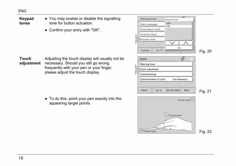
Keypad tones
● You may enable or disable the signalling tone for button actuation.
● Confirm your entry with "OK".
Fig. 20
Touch adjustment
Adjusting the touch display will usually not be necessary. Should you still go wrong frequently with your pen or your finger, please adjust the touch display.
Fig. 21
● To do this, point your pen exactly into the appearing target points.
Fig. 22
ENG
17
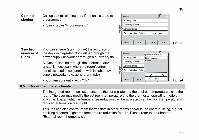
Commis-sioning
Call up commissioning only if the unit is to be re-programmed.
● See chapter "Programming".
Fig. 23
Synchro-nisation of Clock
You can ensure (synchronise) the accuracy of the device-integrated clock either through the power supply network or through a quartz crystal.
A synchronisation through the internal quartz crystal is necessary when the room/control panels is used in conjunction with instable power supply networks (e.g. generator mode).
● Confirm your entry with "OK". Fig. 24
6.5 Room thermostat, climate
The integrated room thermostat ensures the set climate and the desired temperature inside the room. The user may modify the set room temperature and the thermostat operating mode at any time. E.g. a nighttime temperature reduction can be activated, i.e. the room temperature is reduced automatically at night.
This unit can also control room thermostats in other rooms and/or in the entire building, e.g. for realizing a central nighttime temperature reduction feature. Please refer to the chapter "External room thermostats".
ENG
18
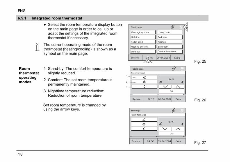
6.5.1 Integrated room thermostat
● Select the room temperature display button on the main page in order to call up or adapt the settings of the integrated room thermostat if necessary.
The current operating mode of the room thermostat (heating/cooling) is shown as a symbol on the main page.
Fig. 25
Room thermostat operating modes
1 Stand-by: The comfort temperature is slightly reduced.
2 Comfort: The set room temperature is permanently maintained.
3 Nighttime temperature reduction: Reduction of room temperature.
Fig. 26
+2,7 K
Start Page
Room thermostat
Set room temperature is changed by
using the arrow keys.
Fig. 27
ENG
19
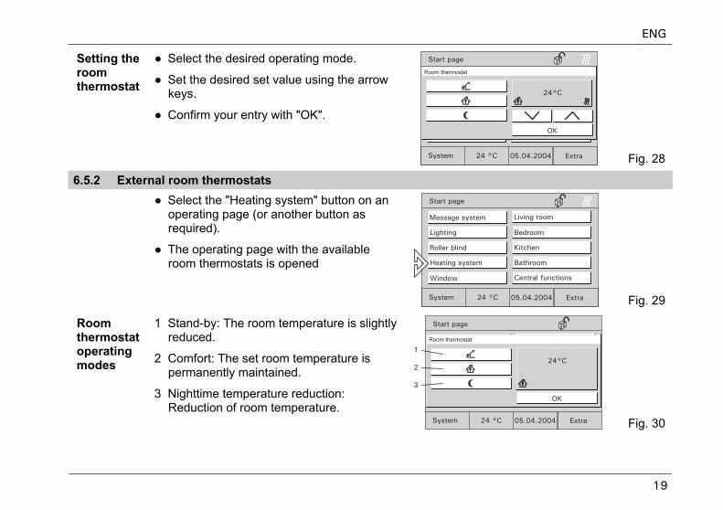
Setting the room thermostat
● Select the desired operating mode.
● Set the desired set value using the arrow keys.
● Confirm your entry with "OK".
Fig. 28
6.5.2 External room thermostats ● Select the "Heating system" button on an
operating page (or another button as required).
● The operating page with the available room thermostats is opened
Fig. 29
Room thermostat operating modes
1 Stand-by: The room temperature is slightly reduced.
2 Comfort: The set room temperature is permanently maintained.
3 Nighttime temperature reduction: Reduction of room temperature.
Fig. 30
ENG
20
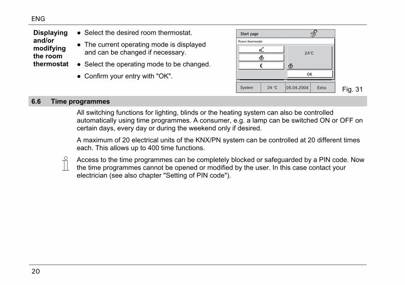
Displaying and/or modifying the room thermostat
● Select the desired room thermostat.
● The current operating mode is displayed and can be changed if necessary.
● Select the operating mode to be changed.
● Confirm your entry with "OK".
Fig. 31
6.6 Time programmes
All switching functions for lighting, blinds or the heating system can also be controlled automatically using time programmes. A consumer, e.g. a lamp can be switched ON or OFF on certain days, every day or during the weekend only if desired.
A maximum of 20 electrical units of the KNX/PN system can be controlled at 20 different times each. This allows up to 400 time functions.
Access to the time programmes can be completely blocked or safeguarded by a PIN code. Now the time programmes cannot be opened or modified by the user. In this case contact your electrician (see also chapter "Setting of PIN code").
ENG
21
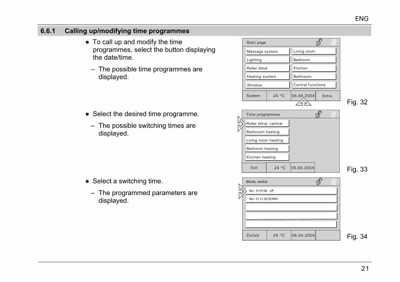
6.6.1 Calling up/modifying time programmes ● To call up and modify the time
programmes, select the button displaying the date/time.
– The possible time programmes are displayed.
Fig. 32
● Select the desired time programme.
– The possible switching times are displayed.
Fig. 33
● Select a switching time.
– The programmed parameters are displayed.
Fig. 34
Mo - Fr 07:00 UP
Mo - Fr 21:30 DOWN
Blinds, central
ENG
22
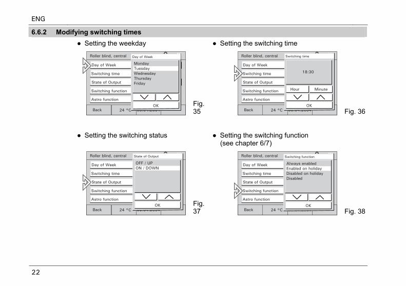
6.6.2 Modifying switching times ● Setting the weekday ● Setting the switching time
Fig. 35 Fig. 36
● Setting the switching status
● Setting the switching function (see chapter 6/7)
Fig. 37 Fig. 38
ENG
23
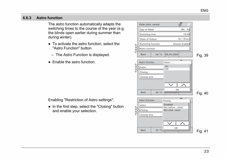
6.6.3 Astro function The astro function automatically adapts the
switching times to the course of the year (e.g. the blinds open earlier during summer than during winter).
● To activate the astro function, select the "Astro Function" button.
– The Astro Function is displayed. Fig. 39
● Enable the astro function.
Fig. 40
Enabling "Restriction of Astro settings":
● In the first step, select the "Closing" button and enable your selection.
Fig. 41
ENG
24
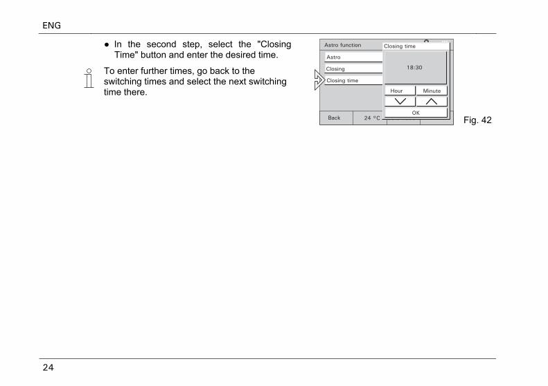
● In the second step, select the "Closing Time" button and enter the desired time.
To enter further times, go back to the switching times and select the next switching time there.
Fig. 422
ENG
25
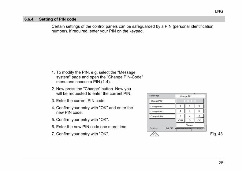
6.6.4 Setting of PIN code
Certain settings of the control panels can be safeguarded by a PIN (personal identification number). If required, enter your PIN on the keypad.
PIN code-protected areas may be:
● Modification of system settings
● Modification of time programmes
● Activation of message system
1. To modify the PIN, e.g. select the "Message system" page and open the "Change PIN-Code"menu and choose a PIN (1-4).
2. Now press the "Change" button. Now you will be requested to enter the current PIN.
3. Enter the current PIN code.
4. Confirm your entry with "OK" and enter the new PIN code.
5. Confirm your entry with "OK".
6. Enter the new PIN code one more time.
7. Confirm your entry with "OK". Fig. 43
Change PIN
Change PIN 1
Change PIN 2
Change PIN 3
Change PIN 4
Change
Start Page
ENG
26
6.7 Holiday and presence simulation
Holiday function
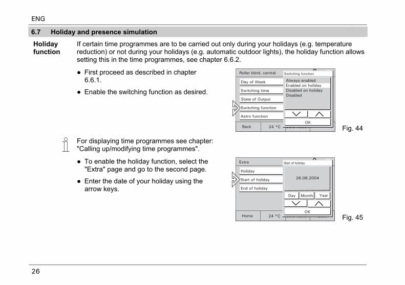
If certain time programmes are to be carried out only during your holidays (e.g. temperature reduction) or not during your holidays (e.g. automatic outdoor lights), the holiday function allows setting this in the time programmes, see chapter 6.6.2.
● First proceed as described in chapter 6.6.1.
● Enable the switching function as desired.
Fig. 44
For displaying time programmes see chapter: "Calling up/modifying time programmes".
● To enable the holiday function, select the "Extra" page and go to the second page.
● Enter the date of your holiday using the arrow keys.
Fig. 45
ENG
27
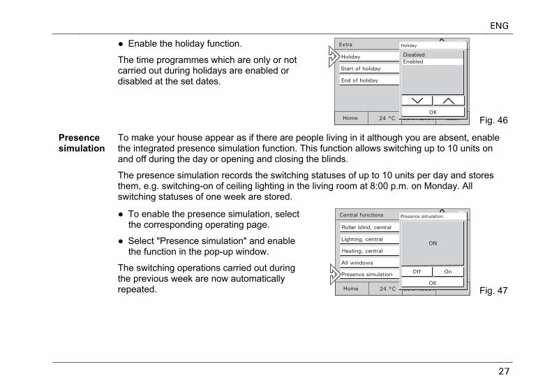
● Enable the holiday function.
The time programmes which are only or not carried out during holidays are enabled or disabled at the set dates.
Fig. 46
Presence simulation
To make your house appear as if there are people living in it although you are absent, enable the integrated presence simulation function. This function allows switching up to 10 units on and off during the day or opening and closing the blinds.
The presence simulation records the switching statuses of up to 10 units per day and stores them, e.g. switching-on of ceiling lighting in the living room at 8:00 p.m. on Monday. All switching statuses of one week are stored.
● To enable the presence simulation, select the corresponding operating page.
● Select "Presence simulation" and enable the function in the pop-up window.
The switching operations carried out during the previous week are now automatically repeated. Fig. 47
ENG
28
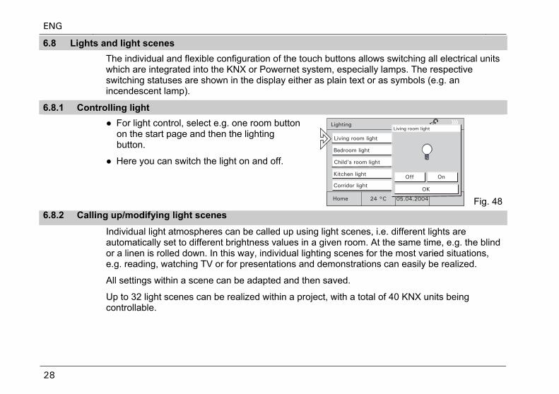
6.8 Lights and light scenes The individual and flexible configuration of the touch buttons allows switching all electrical units
which are integrated into the KNX or Powernet system, especially lamps. The respective switching statuses are shown in the display either as plain text or as symbols (e.g. an incendescent lamp).
6.8.1 Controlling light ● For light control, select e.g. one room button
on the start page and then the lighting button.
● Here you can switch the light on and off.
Fig. 486.8.2 Calling up/modifying light scenes
Individual light atmospheres can be called up using light scenes, i.e. different lights are automatically set to different brightness values in a given room. At the same time, e.g. the blind or a linen is rolled down. In this way, individual lighting scenes for the most varied situations, e.g. reading, watching TV or for presentations and demonstrations can easily be realized.
All settings within a scene can be adapted and then saved.
Up to 32 light scenes can be realized within a project, with a total of 40 KNX units being controllable.
ENG
29
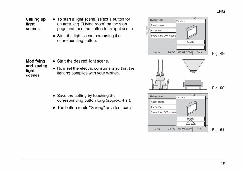
Calling up light scenes
● To start a light scene, select a button for an area, e.g. "Living room" on the start page and then the button for a light scene.
● Start the light scene here using the corresponding button.
Fig. 49
Modifying and saving light scenes
● Start the desired light scene.
● Now set the electric consumers so that the lighting complies with your wishes.
Fig. 50
● Save the setting by touching the corresponding button long (approx. 4 s.).
● The button reads "Saving" as a feedback.
Fig. 51
ENG
30
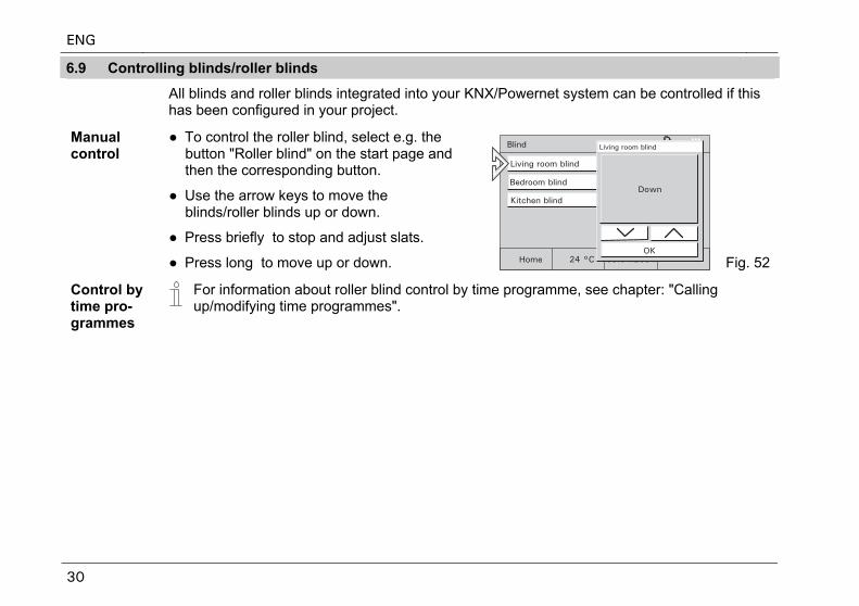
6.9 Controlling blinds/roller blinds
All blinds and roller blinds integrated into your KNX/Powernet system can be controlled if this has been configured in your project.
Manual control
● To control the roller blind, select e.g. the button "Roller blind" on the start page and then the corresponding button.
● Use the arrow keys to move the blinds/roller blinds up or down.
● Press briefly to stop and adjust slats.
● Press long to move up or down. Fig. 52
Control by time pro-grammes
For information about roller blind control by time programme, see chapter: "Calling up/modifying time programmes".
ENG
31
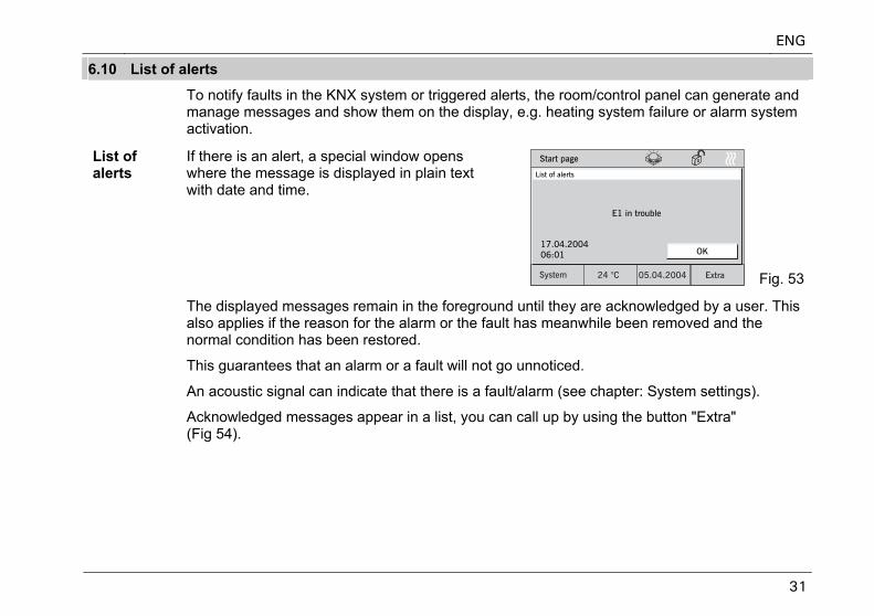
6.10 List of alerts
To notify faults in the KNX system or triggered alerts, the room/control panel can generate and manage messages and show them on the display, e.g. heating system failure or alarm system activation.
List of alerts
If there is an alert, a special window opens where the message is displayed in plain text with date and time.
Fig. 53
The displayed messages remain in the foreground until they are acknowledged by a user. This also applies if the reason for the alarm or the fault has meanwhile been removed and the normal condition has been restored.
This guarantees that an alarm or a fault will not go unnoticed.
An acoustic signal can indicate that there is a fault/alarm (see chapter: System settings).
Acknowledged messages appear in a list, you can call up by using the button "Extra" (Fig 54).
ENG
32
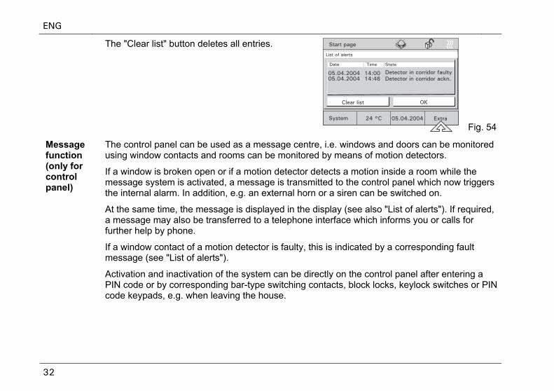
The "Clear list" button deletes all entries.
Fig. 54
Message function (only for control panel)
The control panel can be used as a message centre, i.e. windows and doors can be monitored using window contacts and rooms can be monitored by means of motion detectors.
If a window is broken open or if a motion detector detects a motion inside a room while the message system is activated, a message is transmitted to the control panel which now triggers the internal alarm. In addition, e.g. an external horn or a siren can be switched on.
At the same time, the message is displayed in the display (see also "List of alerts"). If required, a message may also be transferred to a telephone interface which informs you or calls for further help by phone.
If a window contact of a motion detector is faulty, this is indicated by a corresponding fault message (see "List of alerts").
Activation and inactivation of the system can be directly on the control panel after entering a PIN code or by corresponding bar-type switching contacts, block locks, keylock switches or PIN code keypads, e.g. when leaving the house.
ENG
33
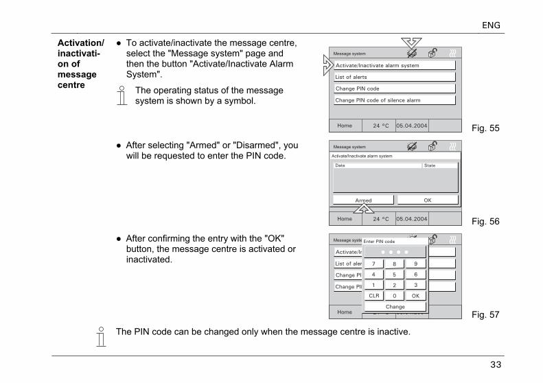
● To activate/inactivate the message centre, select the "Message system" page and then the button "Activate/Inactivate Alarm System".
Activation/ inactivati-on of message centre
The operating status of the message system is shown by a symbol.
Fig. 55
● After selecting "Armed" or "Disarmed", you will be requested to enter the PIN code.
Fig. 56
● After confirming the entry with the "OK" button, the message centre is activated or inactivated.
Fig. 57
The PIN code can be changed only when the message centre is inactive.
ENG
34
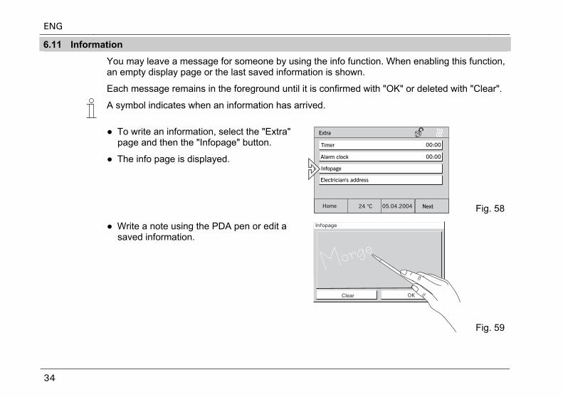
6.11 Information
You may leave a message for someone by using the info function. When enabling this function, an empty display page or the last saved information is shown.
Each message remains in the foreground until it is confirmed with "OK" or deleted with "Clear".
A symbol indicates when an information has arrived.
● To write an information, select the "Extra" page and then the "Infopage" button.
● The info page is displayed.
Fig. 58
● Write a note using the PDA pen or edit a saved information.
Fig. 59
ENG
35
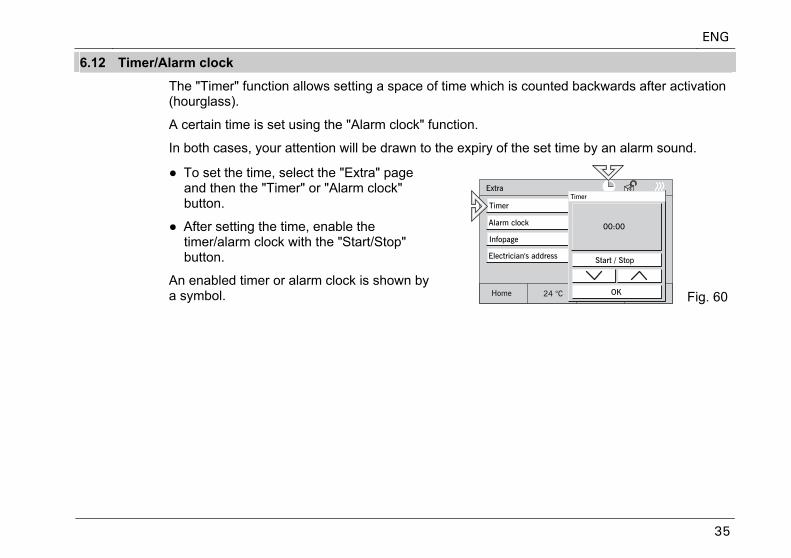
6.12 Timer/Alarm clock
The "Timer" function allows setting a space of time which is counted backwards after activation (hourglass).
A certain time is set using the "Alarm clock" function.
In both cases, your attention will be drawn to the expiry of the set time by an alarm sound.
● To set the time, select the "Extra" page and then the "Timer" or "Alarm clock" button.
● After setting the time, enable the timer/alarm clock with the "Start/Stop" button.
An enabled timer or alarm clock is shown by a symbol. Fig. 60
ENG
36
7 Remote control
7.1 Busch-Jaeger hand-held transmitter 6010-25
All control panels are equipped with an infrared receiver and may be remote-controlled with the Busch-Jaeger hand-held transmitters 6010-25 and 6010-25-500.
For detailed information and operating information, please refer to the separate Instruction Manual of the hand-held transmitter.
Fig. 61
ENG
37
7.2 Bang & Olufsen hand-held transmitter BEO4
The Bang & Olufsen hand-held transmitter BEO4 only works together with the control panels 6136/100CB and 6936/100CB.
The IR hand-held transmitter provides the following possibilities for controlling the room panel:
Light: Modification of lighting
List: Saving a light scene
0 – 9: Selection of lamp 1 to 10
A: Selection of light scene 1
C: Selection of light scene 2
D: Selection of light scene 3
F: Selection of light scene 4
B: On or brighter
E: Off or darker
Stop: Everything off
Fig. 62
ENG
38
7.2.1 Switching and dimming of lamps
● Press "Light" button on remote control unit.
– The word "LIGHT" appears in the remote control unit display. This mode is active for 25 seconds. After this, the display goes back to audio/video. Press the LIGHT key one more time if required.
● Switch the lamps according to the table below.
„LIGHT+1+B“ in the table means that these three keys must be pressed one after the other (not simultaneously).
Function Keys to be pressed
Lamp 1 ON LIGHT+1+B
Lamp 1 brighter LIGHT+1+B (press B permanently)
Lamp 1 OFF LIGHT+1+E
Lamp 1 darker LIGHT+1+E (press E permanently)
Lamps 2 – 9 are actuated in the same way as lamp 1.
Lamp 10 ON LIGHT+0+B
Lamp 10 brighter LIGHT+0+B (press B permanently)
Lamp 10 OFF LIGHT+0+E
Lamp 10 darker LIGHT+0+E (press E permanently)
ENG
39
7.2.2 Calling up and saving light scenes
● Press "Light" button on remote control unit.
– The word "LIGHT" appears in the remote control unit display. This mode is active for 25 seconds. After this, the display goes back to audio/video. Press the LIGHT key one more time if required.
● Switch the light scenes according to the table below.
„LIGHT+A“ in the table means that these two keys must be pressed one after the other (not simultaneously).
Function Keys to be pressed
Call up light scene 1 LIGHT+A
Call up light scene 2 LIGHT+C
Call up light scene 3 LIGHT+D
Call up light scene 4 LIGHT+F
Save light scene 1 LIGHT+ LIST*+GO+A
Save light scene 2 LIGHT+ LIST*+GO +C
Save light scene 3 LIGHT+ LIST*+GO +D
Save light scene 4 LIGHT+ LIST*+GO +F
* The key LIST must be pressed until STORE appears in the display.
7.2.3 Switching off the consumers When pressing the "STOP" button, all consumers can be switched off with one single button.
ENG
40
8 Installation
8.1 Electric installation
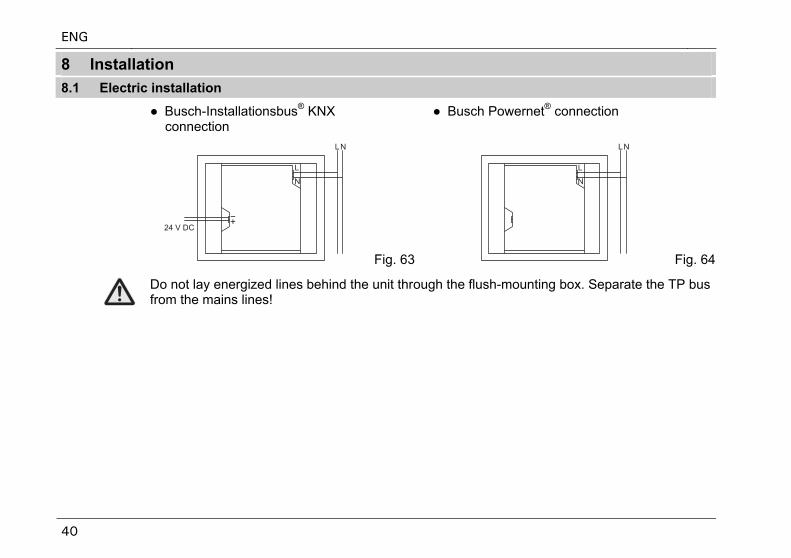
● Busch-Installationsbus® KNX connection
● Busch Powernet® connection
Fig. 63 Fig. 64
Do not lay energized lines behind the unit through the flush-mounting box. Separate the TP bus from the mains lines!
ENG
41
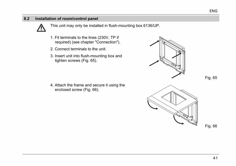
8.2 Installation of room/control panel
This unit may only be installed in flush-mounting box 6136/UP.
1. Fit terminals to the lines (230V, TP if required) (see chapter "Connection").
2. Connect terminals to the unit.
3. Insert unit into flush-mounting box and tighten screws (Fig. 65).
Fig. 65
4. Attach the frame and secure it using the enclosed screw (Fig. 66).
Fig. 66
ENG
42
9 Software
9.1 Installation
ETS
(from V. 1.3)
1. Install the panel commissioning software from the current KNX database on a PC.
2. Import the product database into the ETS.
3. Configure the unit and set the parameters.
Power-Projekt >4.5
1. Install the panel commissioning software from the current KNX database or from the Power-Projekt CD.
2. Configure the unit and set the parameters (see above).
The KNX database can be purchased directly from Busch-Jaeger or downloaded from the Internet at www.BUSCH-JAEGER.de.
ENG
43
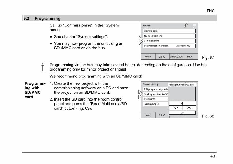
9.2 Programming
Call up "Commissioning" in the "System" menu.
● See chapter "System settings".
● You may now program the unit using an SD-/MMC card or via the bus.
Fig. 67
Programming via the bus may take several hours, depending on the configuration. Use bus progamming only for minor project changes!
We recommend programming with an SD/MMC card!
Programm-ing with SD/MMC card
1. Create the new project with the commissioning software on a PC and save the project on an SD/MMC card.
2. Insert the SD card into the room/control panel and press the "Read Multimedia/SD card" button (Fig. 69).
Fig. 68
ENG
44
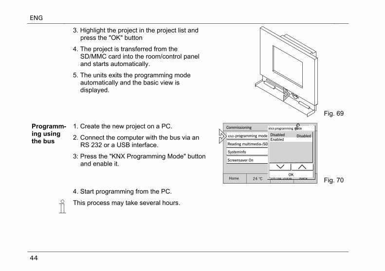
3. Highlight the project in the project list and press the "OK" button
4. The project is transferred from the SD/MMC card into the room/control panel and starts automatically.
5. The units exits the programming mode automatically and the basic view is displayed.
Fig. 69
Programm-ing using the bus
1. Create the new project on a PC.
2. Connect the computer with the bus via an RS 232 or a USB interface.
3: Press the "KNX Programming Mode" button and enable it.
KNX
KNX
Fig. 70
4. Start programming from the PC.
This process may take several hours.
ENG
45
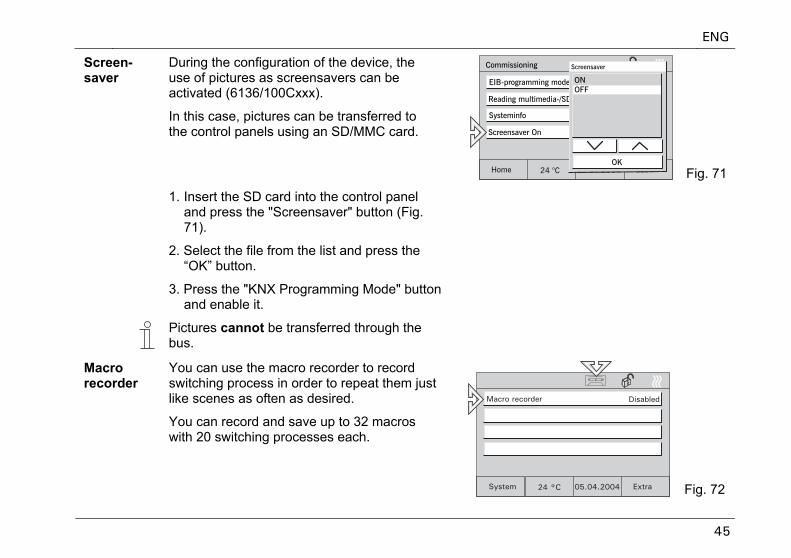
Screen-saver
During the configuration of the device, the use of pictures as screensavers can be activated (6136/100Cxxx).
In this case, pictures can be transferred to the control panels using an SD/MMC card.
Fig. 71
1. Insert the SD card into the control panel and press the "Screensaver" button (Fig. 71).
2. Select the file from the list and press the “OK” button.
3. Press the "KNX Programming Mode" button and enable it.
Pictures cannot be transferred through the bus.
Macro recorder
You can use the macro recorder to record switching process in order to repeat them just like scenes as often as desired.
You can record and save up to 32 macros with 20 switching processes each.
Fig. 72
ENG
46
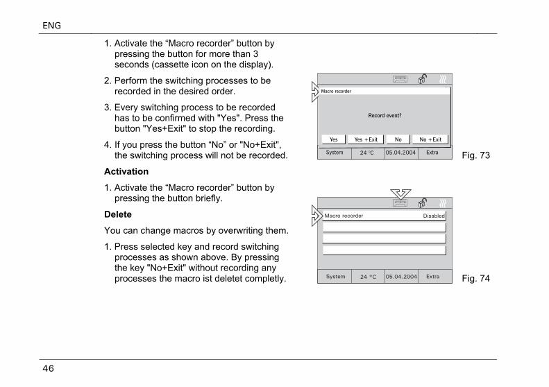
1. Activate the “Macro recorder” button by pressing the button for more than 3 seconds (cassette icon on the display).
2. Perform the switching processes to be recorded in the desired order.
3. Every switching process to be recorded has to be confirmed with "Yes". Press the button "Yes+Exit" to stop the recording.
4. If you press the button “No” or "No+Exit", the switching process will not be recorded. Fig. 73
Activation
1. Activate the “Macro recorder” button by pressing the button briefly.
Delete
You can change macros by overwriting them.
1. Press selected key and record switching processes as shown above. By pressing the key "No+Exit" without recording any processes the macro ist deletet completly. Fig. 74