77012005xxx 81212005xxx 77212905344 Offroad ... · DEUTSCH 3 Lieferumfang 77012005000 SXS...
27
INFORMATION KTM PowerParts, HUSQVARNA Husky Power, HUSABERG Pure Tech KTM - Sportmotorcycle AG Stallhofnerstraße 3 A-5230 Mattighofen www.ktm.com Husqvarna Motorcycles GmbH Stallhofnerstraße 3 A-5230 Mattighofen www.husqvarna-motorcycles.com KTM - Sportmotorcycle AG Division HUSABERG Stallhofnerstraße 3 A-5230 Mattighofen www.husaberg.com STEERING DAMPER 3.211.395 *3211395* 77012005000 77012005544 77012005044 77212905344 77012005144 77012005444 04.2014
Transcript of 77012005xxx 81212005xxx 77212905344 Offroad ... · DEUTSCH 3 Lieferumfang 77012005000 SXS...

INFORMATION
KTM PowerP
arts, H
USQVARNA Husk
y Pow
er, HUSABERG Pure
Tech
KTM - Sportmotorcycle AG Stallhofnerstraße 3A-5230 Mattighofen www.ktm.com
Husqvarna Motorcycles GmbHStallhofnerstraße 3A-5230 Mattighofenwww.husqvarna-motorcycles.com
KTM - Sportmotorcycle AGDivision HUSABERGStallhofnerstraße 3A-5230 Mattighofenwww.husaberg.com
STEERING DAMPER3.211.395
*3211395*
77012005000 7701200554477012005044 7721290534477012005144 77012005444
04.2014

Le agradecemos que se haya decidido por este producto.Este producto de alta calidad está probado para la competición y se ha desarrollado específi camente para las exigencias de este deporte. Para poder garantizar los máximos niveles de seguridad y funcionalidad, es imprescindible que el producto se monte correctamente. Por este motivo, es muy importante que siga las instrucciones del manual de montaje o que se ponga en contacto con su concesionario autorizado. El (cuasi) fabricante y el proveedor de este producto no se harán responsables del montaje y el uso incorrectos.¡Muchas gracias!
Wir freuen uns, dass Sie sich für dieses Produkt entschieden haben.Unser hochwertiges Qualitätsprodukt ist rennerprobt und wurde speziell für sportliche Herausforderungen entwickelt. Eine korrekte Montage des Produktes ist unerlässlich, um ein Maximum an Sicherheit und Funktionalität gewährleisten zu können. Bitte befolgen Sie daher die Montageanleitung oder wenden Sie sich an Ihren autorisierten Fachhändler. Für falsche Montage oder Verwendung dieses Produktes kann der (Quasi) Hersteller bzw. Lieferant nicht zur Verantwortung gezogen werden.Vielen Dank.
Thank you for choosing this product.Our high quality product has been tested under racing conditions and was developed specifi cally for use in sports activities. Correct installation of the pro-duct is essential to ensure that a maximum degree of safety and functionality is achieved. Therefore, please follow the installation instructions or contact your authorized dealer. The (quasi) manufacturer or supplier cannot be held responsible for products that are incorrectly mounted or inappropriately used.Thank you.
Grazie per aver scelto questo prodotto.Questo nostro prodotto di pregiata qualità è collaudato nelle competizioni ed è stato sviluppato specifi camente per gare sportive. Il montaggio corretto del prodotto è fondamentale per garantirne la massima sicurezza e funzionalità. Rispettare quindi le istruzioni di montaggio o rivolgersi al proprio concessio-nario autorizzato. Il produttore (detentore del marchio)/fornitore non può essere considerato responsabile per un montaggio o impiego errato del presente prodotto.aVi ringraziamo per l’attenzione!
Merci d‘avoir porté votre choix sur ce produit.Notre produit de haute qualité est éprouvé pour les compétitions et a été conçu spécialement pour un usage sportif. Un montage approprié du produit est indispensable pour garantir une sécurité et une fonctionnalité maximales du véhicule. C‘est pourquoi nous vous invitons à suivre scrupuleusement le manuel de montage ou à vous adresser à votre revendeur agréé. En cas de montage ou d‘utilisation non conformes de ce produit, le (quasi )constructeur ou le fournisseur déclinent toute responsabilité.Merci !
8 ENGLISH
13 ITALIANO
18 FRANÇAIS
23 ESPAÑOL
3 DEUTSCH
DEU
TSCH
3
Lieferumfang
77012005000 SXS LENKUNGSDÄMPFER
77012005044 HALTERUNG GABELBRÜCKE
1x Lenkungsdämpfer Halter EXC inks1x Lenkungsdämpfer Halter EXC rechts2x Zylinderschraube M10x45 09121004562x Zylinderschraube M8x25 09120802532x Distanzbüchse 8.5mm 548080200002x Sechskantbundschraube M6x30 0015060303
77012005144 HALTERUNG GABELBRÜCKE1x Lenkungsdämpfer Halter links1x Lenkungsdämpfer Halter rechts2x Zylinderschraube M10x502x Zylinderschraube M8x25 0912080253
77012005544 HALTERUNG WERKSGABELBRÜCKE1x Lenkungsdämpfer Halter links1x Lenkungsdämpfer Halter rechts2x Zylinderschraube M10x602x Zylinderschraube M8x25 0912080253
77212905344 WIDERLAGER LENKUNGSDÄMPFER1x Gewindestift M6x161x Gewindestift M6x201x Schutzring2x Senkschraube M6x201x Zylinderschraube M6x401x Lenkungsdämpfer Bolzen 1x Lenkungsdämpfer Halter1x Lenkungsdämpfer Schelle
77012005444 HALTERUNG SMR GABELBRÜCKE MIT VERSATZ 14-16mm1x Lenkungsdämpfer Halter links1x Lenkungsdämpfer Halter rechts2x Zylinderschraube M10x502x Zylinderschraube M8x25 09120802532x Distanzbüchse 12x6,2x152x Sechskantbundschraube M6x30 0015060303
DEU
TSCH
4
Hinweis zum SXS Lenkungsdämpfer:Es kann vorkommen, dass der Lenkungsdämpfer im Auslieferungszustandleicht "ölig" ist. Dies bedeutet nicht, dass der Lenkungsdämpfer undichtist, sondern hängt lediglich mit der Befüllung im Ölbad zusammen, dieseÖlreste können Sie mit einen Tuch entfernen!
Montageanleitung:
Das gereinigte Motorrad mit einem geeigneten Montageständer so aufbocken, dass das Gewicht des Motorrades am Vorderrad aufliegt; das Vorderrad zusätzlich fixieren, damit es nicht nach vorne wegrollen kann. Achtung: Wenn die obere Gabelbrücke entfernt ist, kann ein wegrutschenbzw. nach unten tauchen der Gabel sehr leicht passieren !
Lichtmaske bzw. Startnummerntafel, sowie Tacho entfernen.
Schrauben der Lenkerklemmbrücken lösen und Lenker entfernen
Vorderrad so fixieren, dass es nicht nach vorne abrollen kann.
Obere Gabelbrücke demontieren, gegebenenfalls mit Gummihammer leichtnachhelfen. Darauf achten, dass sich die Gabelbrücke dabei nichtverkantet. Klemmschrauben der oberen Gabelbrücke lockern undSteuerkopfschraube M20 (SW27) losschrauben. O-Ring, Schutzring und Steuerkopfabdichtung, sofern vorhanden,abnehmen.Achtung: Wird später wieder zum Zusammenbau benötigt - Einbaulagemerken!
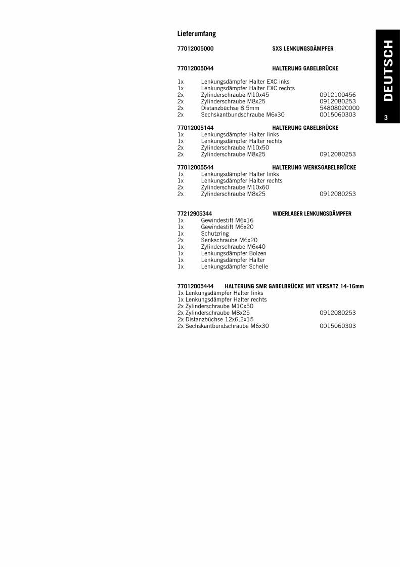
Montage Widerlager
Widerlager zusammenbauen
Senkschrauben M6x20 mit Loctite 243 sichern, Schelle (1) und Halter (2)damit verschrauben und mit 15 Nm anziehen.
1
2
Grundeinstellung Widerlager Seriengabelbrücke
Gewindestift M6x16 mm (3) mit Loctite 243 sichern und von obeneinschrauben. Bolzen in den Halter einschieben und Überstand messen.Gewindestift so justieren, dass der Bolzen (4) 18 mm weit heraus steht.HINWEIS: Der Bolzen ist im Auslieferungszustand geschmiert und solltevon Zeit zu Zeit nachgeschmiert werden. Auch auf Freigängigkeit ist zuachten.
183
4
Abb. 77012005344
DEU
TSCH
5
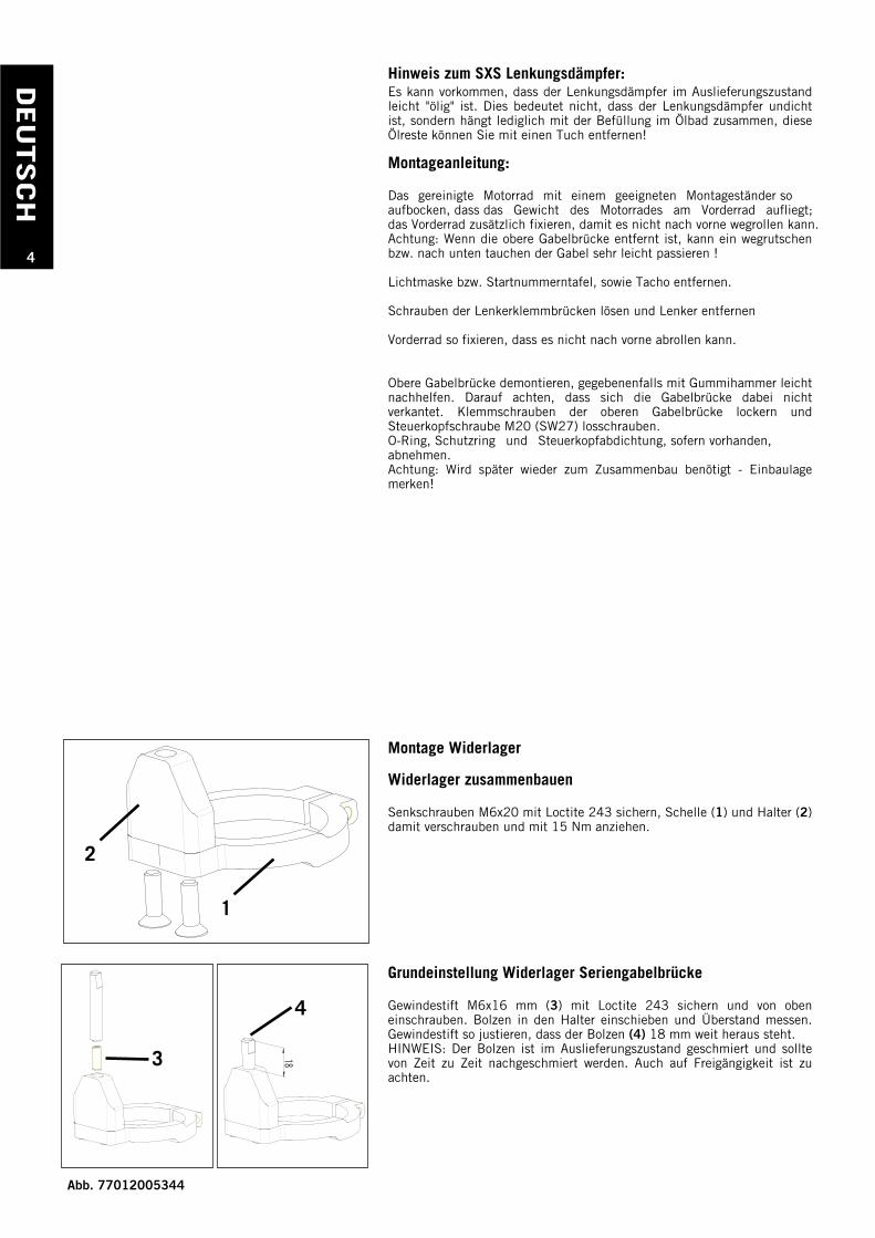
Grundeinstellung Widerlager für Werksgabelbrücke
Gewindestift M6x20 mm (1) mit Loctite 243 sichern und von obeneinschrauben. Bolzen in den Halter einschieben und Überstand messen.Gewindestift so justieren, dass der Bolzen (2) 23 mm weit heraus steht.HINWEIS: Der Bolzen ist im Auslieferungszustand geschmiert und solltevon Zeit zu Zeit nachgeschmiert werden. Auch auf Freigängigkeit ist zuachten.
23231
2
Das Steuerkopfrohr im oberen Bereich in dem das Widerlager befestigtwird (siehe Bild) gründlich reinigen. Auf Fettfreiheit achten! Widerlagerüber Steuerkopfrohr schieben, nötigenfalls einen Keil od. Schraubenzieherin den Spalt des Rings treiben, sodass sich der Ring über dasSteuerkopfrohr schieben lässt. Obere Ebene der Schelle (3) bündig mitdem Rahmen (4) justieren (siehe Bild), das Widerlager so ausrichten, dassder Bolzen in der Rahmen- bzw. Fahrzeugmitte liegt !Innensechskantschraube M6x40 mit Loctite 243 sichern und 10 Nmanziehen, vergewissern Sie sich, dass das Widerlager gut am ganzenUmfang des Steuerkopfrohres aufliegt und fest sitzt !Anschließend beigelegten kürzeren Schutzring mit Steuerkopfabdichtungund O-Ring wieder in der selben Weise montieren wie er demontiert wurde. Der Abstand des Schutzringes zum Widerlager ist knapp bemessen, vermeiden sie aber ein Streifen des Schutzringes am Widerlager. Obere Gabelbrücke vorsichtig montieren; achten Sie darauf, dass dasVorderrad nicht wegrutschen kann und vergewissern Sie sich, dass dieGabelbrücke richtig im Steuerkopf sitzt, bzw. die Kegelrollenlager desGabelschaftrohres richtig in den Lagerschalen sind und sich nichtverkanten. Nun die Steuerkopfschraube M20 (SW27) wieder anziehen,Steuerkopflagerung laut Bedienungsanleitung einstellen und prüfen.
Bei Modellen mit Tacho diesen wieder montieren und zwischen Tacho undSteckerboard, ab Modelljahr 2005 - oder je nach Bedarf - die beigelegtenDistanzbüchsen (5) 8,5mm mit der beigelegten Sechskantbundschraube(6) M6x30 verschrauben. Freigängigkeit der Gabelbrücke überprüfengegebenenfalls freistehende Kabel am Steckerboard zusätzlich mitKabelbinder an den Steckern so fixieren, dass sie nicht an der vorderenVerschraubung des Widerlagers streifen.
56
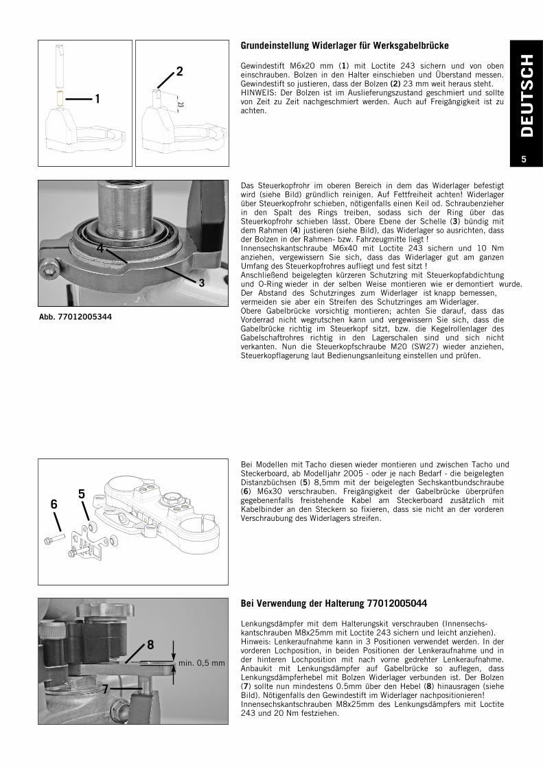
Bei Verwendung der Halterung 77012005044
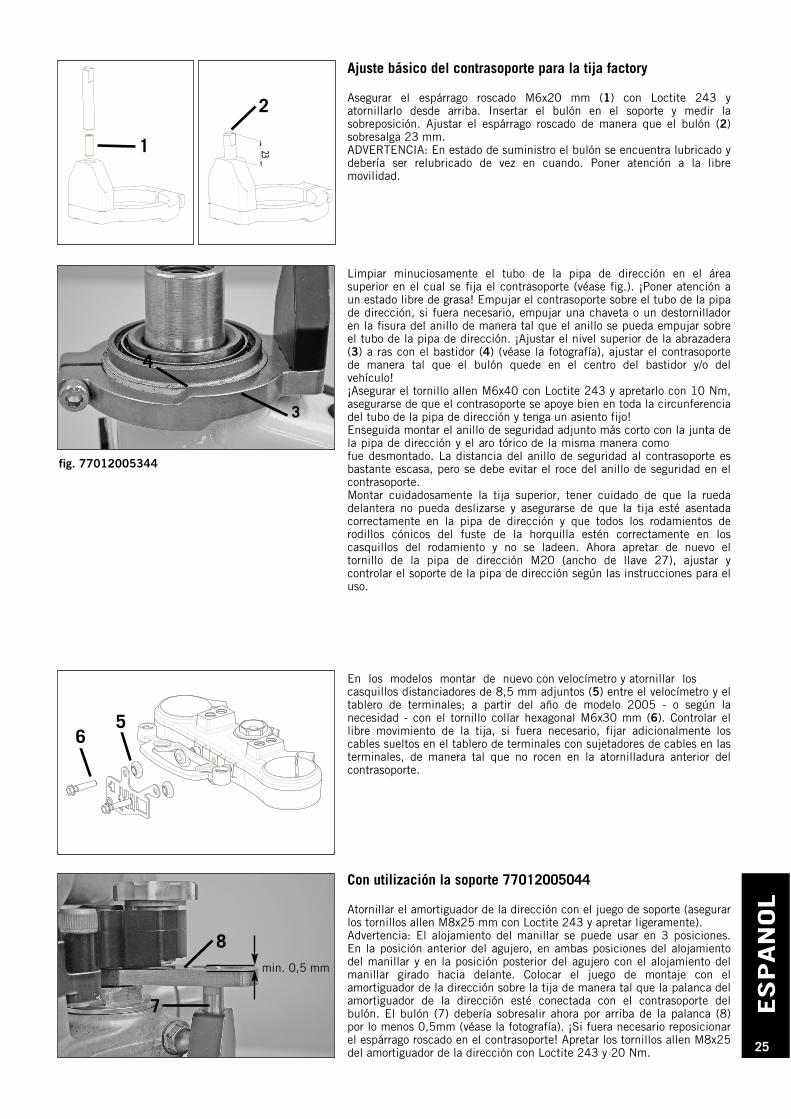
Lenkungsdämpfer mit dem Halterungskit verschrauben (Innensechs-kantschrauben M8x25mm mit Loctite 243 sichern und leicht anziehen).Hinweis: Lenkeraufnahme kann in 3 Positionen verwendet werden. In dervorderen Lochposition, in beiden Positionen der Lenkeraufnahme und inder hinteren Lochposition mit nach vorne gedrehter Lenkeraufnahme.Anbaukit mit Lenkungsdämpfer auf Gabelbrücke so auflegen, dassLenkungsdämpferhebel mit Bolzen Widerlager verbunden ist. Der Bolzen(7) sollte nun mindestens 0.5mm über den Hebel (8) hinausragen (sieheBild). Nötigenfalls den Gewindestift im Widerlager nachpositionieren!Innensechskantschrauben M8x25mm des Lenkungsdämpfers mit Loctite243 und 20 Nm festziehen.
8
7
3
4
min. 0,5 mm
Abb. 77012005344
DEU
TSCH
6
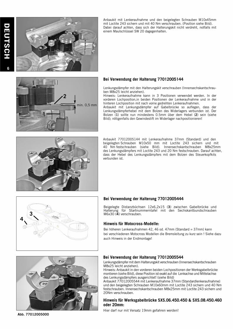
Bei Verwendung der Halterung 77012005144
Lenkungsdämpfer mit den Halterungskit verschrauben (Innensechskantschrau-ben M8x25 leicht anziehen).Hinweis: Lenkeraufnahme kann in 3 Positionen verwendet werden. In dervorderen Lochposition,in beiden Positionen der Lenkeraufnahme und in derhinteren Lochposition mit nach vorne gedrehten Lenkeraufnahmen.Anbaukit mit Lenkungsdämpfer auf Gabelbrücke so auflegen, dass derLenkungsdämpferhebel mit dem Bolzen des Widerlagers verbunden ist. DerBolzen (1) sollte nun mindestens 0.5mm über dem Hebel (2) sein (sieheBild); nötigenfalls den Gewindestift im Widerlager nachpositionieren!
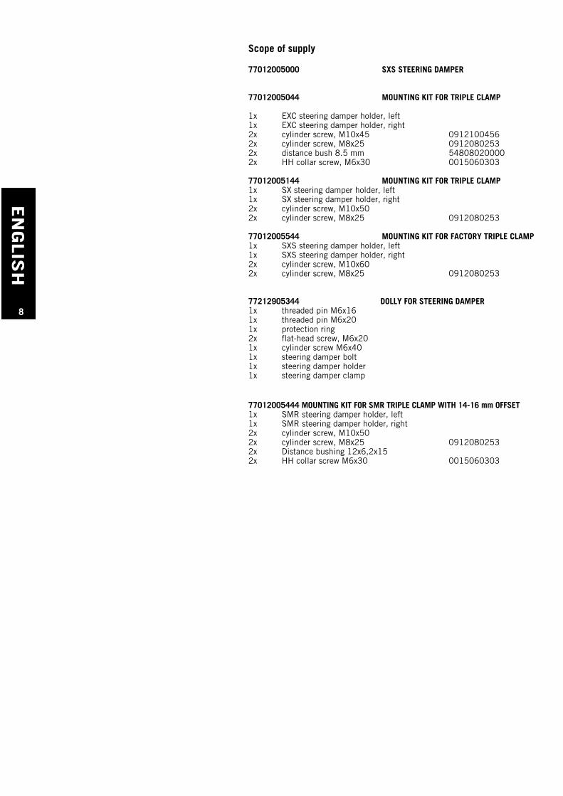
Bei Verwendung der Halterung 77012005544Lenkungsdämpfer mit dem Halterungskit verschrauben (InnensechskantschraubenM8x25 leicht anziehen).Hinweis: Anbaukit in den vorderen beiden Lochpositionen der Werksgabelbrückemontieren (siehe Bild), diese Position ist exakt auf die Lenkachse und Mittelachsedes Lenkungsdämpfers ausgerichtet! (siehe Bild)Anbaukit 77012005544 mit Lenkeraufnahme 37mm (Standardlenkeraufnahme) und den beigelegten Schrauben M10x60mm mit Loctite 243 sichern und 40 Nm festschrauben. Innensechskantschrauben M8x25mm mit Loctite 243 sichern und20Nm verschrauben.
Hinweis für Werksgabelbrücke SXS.06.450.450 & SXS.08.450.460 oder 20mm:Hier darf nur mit Versatz 19mm gefahren werden!
Anbaukit mit Lenkeraufnahme und den beigelegten Schrauben M10x45mmmit Loctite 243 sichern und mit 40 Nm verschrauben. (Position siehe Bild).Dabei darauf achten, dass sich der Halterungskit nicht verdreht, notfalls miteinem Maulschlüssel SW 20 dagegenhalten.
2
1
Anbaukit 77012005144 mit Lenkeraufnahme 37mm (Standard) und den beigelegten Schrauben M10x50 mm mit Loctite 243 sichern und mit 40 Nm festschrauben (siehe Bild). Innensechskantschrauben M8x25mm des Lenkungsdämpfers mit Loctite 243 und 20 Nm festschrauben. Darauf achten,dass der Hebel des Lenkungsdämpfers mit dem Bolzen des Steuerkopfkitsverbunden ist.
min. 0,5 mm
34
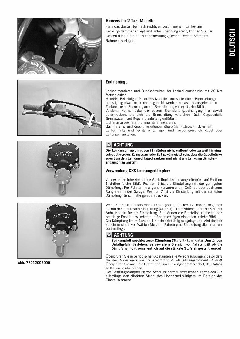
Bei Verwendung der Halterung 77012005444
Beigelegte Distanzbüchsen 12x6,2x15 (3) zwischen Gabelbrücke undHalterung für Startnummerntafel mit den SechskantbundschraubenM6x30 (4) verschrauben.
Hinweis für Motocross-Modelle:Bei höheren Lenkeraufnahmen 42, 46 od. 47mm (Standard = 37mm) kannbei verschiedenen Motocross Modellen die Bremsleitung zu kurz sein ! Siehe dazuauch Hinweis in der Endmontage!
Abb. 77012005000
DEU
TSCH
7
Endmontage
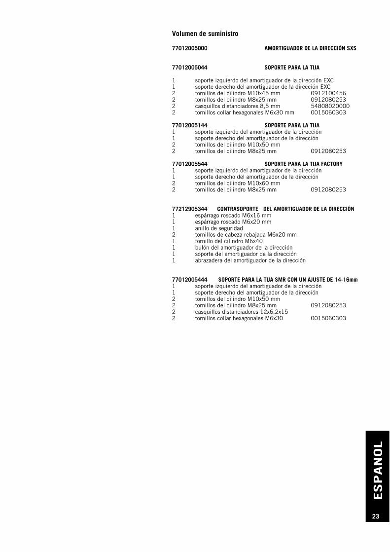
Lenker montieren und Bundschrauben der Lenkerklemmbrücke mit 20 Nmfestschrauben Hinweis: Bei einigen Motocross Modellen muss die obere Bremsleitungs-befestigung etwas nach unten gedreht werden, sodass in ausgefedertem Zustand keine Spannung an der Bremsleitung vorliegt (siehe Bild).Vorsicht: Hohlschraube der oberen Bremsleitungsbefestigung nur soweitaufschrauben, bis sich die Bremsleitung verdrehen lässt. GegebenfallsBremssystem laut Reperaturanleitung entlüften.Lichtmaske bzw. Startnummerntafel montieren.Gas- , Brems- und Kupplungsleitungen überprüfen (Länge/Knickfreiheit).Lenker links und rechts einschlagen und kontrollieren, ob Kabel oderLeitungen anstehen.
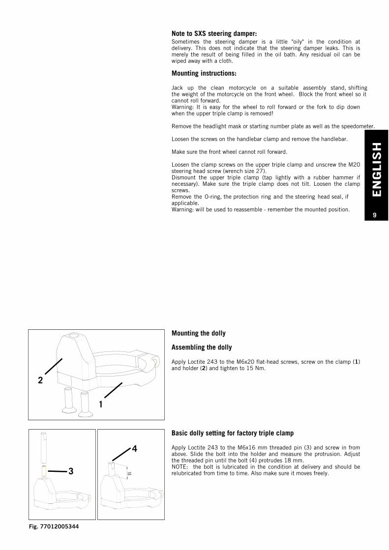
Wenn sie noch niemals einen Lenkungsdämpfer benutzt haben, beginnensie mit der leichtesten Einstellung (Stufe 1)! Die Positionsnummern sind einAnhaltspunkt für die Einstellung, Sie können die Einstellschraube in jedebeliebige Position zwischen den Endanschlägen einstellen. (siehe Bild)Die Dämpfung ist im Bereich 1-4 sehr feinfühlig ausgelegt und wird danachzunehmend stärker. Wählen Sie beim Fahren eine Einstellung die Ihnen ambesten liegt.
– Bei komplett geschlossener Dämpfung (Stufe 7) kann unter UmständenUnfallgefahr bestehen. Vergewissern Sie sich vor Fahrtantritt ob dieDämpfung nicht versehentlich auf die stärkste Stufe eingestellt wurde!
Überprüfen Sie in periodischen Abständen alle Verschraubungen; besondersdie des Widerlagers am Steuerkopfrohr M6x40 (Anzugsmoment 15Nm)!Überprüfen Sie auch die Bolzenhöhe im Lenkungsdämpferhebel; der Bolzensollte leicht überstehen!Der Lenkungsdämpfer ist von Schmutz normal abwaschbar; vermeiden Sieallerdings den direkten Strahl des Hochdruckreinigers im Bereich derEinstellschraube.
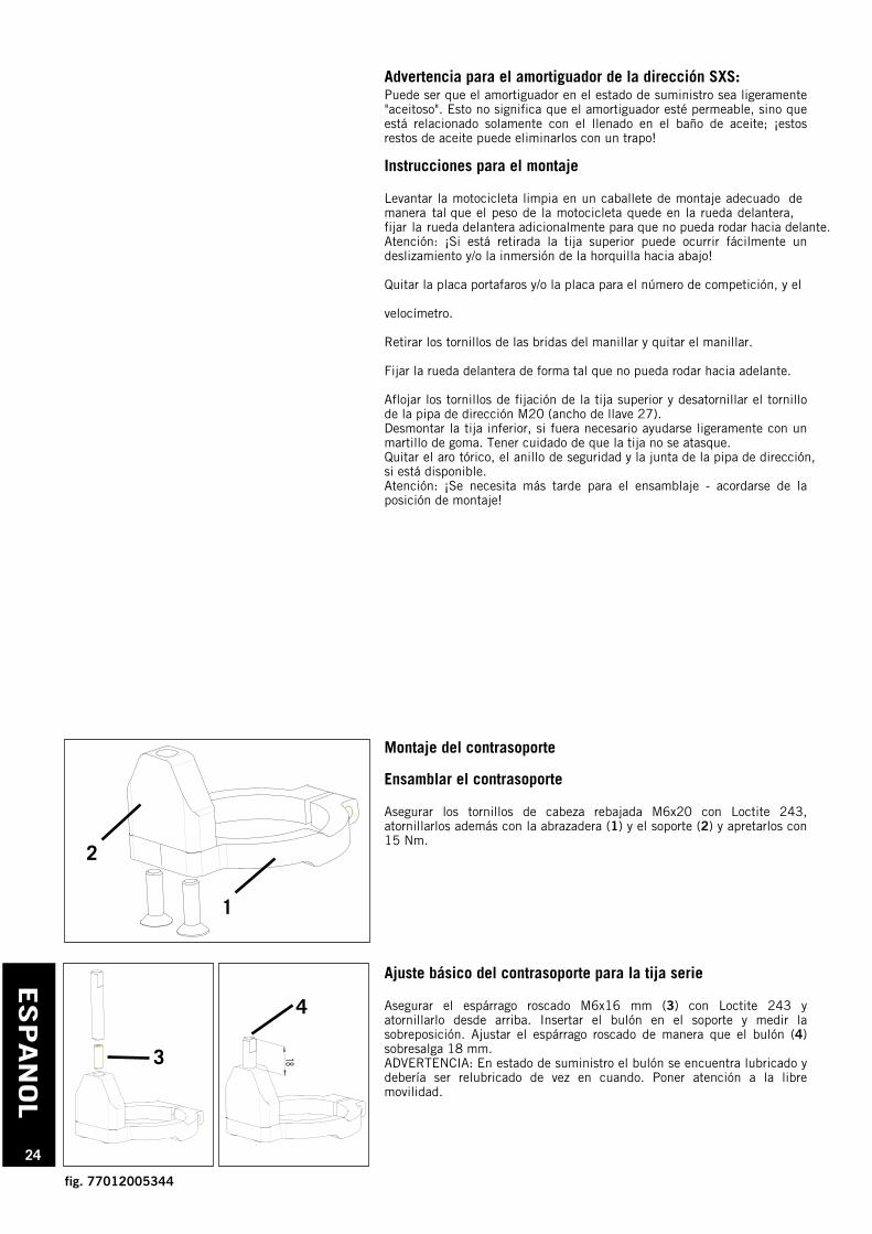
Die Lenkanschlagschrauben (1) dürfen nicht entfernt oder zu weit hineing-schraubt werden. Es muss zu jeder Zeit gewährleistet sein, dass die Gabelbrückezuerst an den Lenkanschlagschrauben und nicht am Lenkungsdämpfer-endanschlag ansteht.
Verwendung SXS Lenkungsdämpfer:
Vor der ersten Inbetriebnahme Verstellrad des Lenkungsdämpfers auf Position1 stellen (siehe Bild). Position 1 ist die Einstellung mit der geringstenDämpfung. Für Fahrten in engem, kurvenreichem Gelände aber auch zumRangieren in der Garage. Position 7 ist die Einstellung mit der stärkstenDämpfung für schnelle gerade Strecken.
1
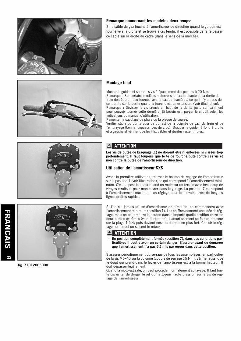
Hinweis für 2 Takt Modelle:Falls das Gasseil bei nach rechts eingeschlagenem Lenker amLenkungsdämpfer anliegt und unter Spannung steht, können Sie dasGasseil auch auf die - in Fahrtrichtung gesehen - rechte Seite desRahmens verlegen.
Abb. 77012005000
EN
GLIS
H
8
Scope of supply
77012005000 SXS STEERING DAMPER
77012005044 MOUNTING KIT FOR TRIPLE CLAMP
1x EXC steering damper holder, left1x EXC steering damper holder, right2x cylinder screw, M10x45 09121004562x cylinder screw, M8x25 09120802532x distance bush 8.5 mm 548080200002x HH collar screw, M6x30 0015060303
77012005144 MOUNTING KIT FOR TRIPLE CLAMP1x SX steering damper holder, left1x SX steering damper holder, right2x cylinder screw, M10x502x cylinder screw, M8x25 0912080253
77012005544 MOUNTING KIT FOR FACTORY TRIPLE CLAMP1x SXS steering damper holder, left1x SXS steering damper holder, right2x cylinder screw, M10x602x cylinder screw, M8x25 0912080253
77212905344 DOLLY FOR STEERING DAMPER1x threaded pin M6x161x threaded pin M6x201x protection ring2x flat-head screw, M6x201x cylinder screw M6x401x steering damper bolt 1x steering damper holder1x steering damper clamp
77012005444 MOUNTING KIT FOR SMR TRIPLE CLAMP WITH 14-16 mm OFFSET1x SMR steering damper holder, left1x SMR steering damper holder, right2x cylinder screw, M10x502x cylinder screw, M8x25 09120802532x Distance bushing 12x6,2x152x HH collar screw M6x30 0015060303
EN
GLI
SH
9
Note to SXS steering damper:Sometimes the steering damper is a little "oily" in the condition atdelivery. This does not indicate that the steering damper leaks. This ismerely the result of being filled in the oil bath. Any residual oil can bewiped away with a cloth.
Mounting instructions:
Jack up the clean motorcycle on a suitable assembly stand, shifting the weight of the motorcycle on the front wheel. Block the front wheel so it cannot roll forward.Warning: It is easy for the wheel to roll forward or the fork to dip downwhen the upper triple clamp is removed!
Remove the headlight mask or starting number plate as well as the speedometer.
Loosen the screws on the handlebar clamp and remove the handlebar.
Make sure the front wheel cannot roll forward.
Loosen the clamp screws on the upper triple clamp and unscrew the M20steering head screw (wrench size 27).Dismount the upper triple clamp (tap lightly with a rubber hammer ifnecessary). Make sure the triple clamp does not tilt. Loosen the clampscrews.Remove the O-ring, the protection ring and the steering head seal, if applicable.Warning: will be used to reassemble - remember the mounted position.
Mounting the dolly
Assembling the dolly
Apply Loctite 243 to the M6x20 flat-head screws, screw on the clamp (1)and holder (2) and tighten to 15 Nm.
1
2
Basic dolly setting for factory triple clamp
Apply Loctite 243 to the M6x16 mm threaded pin (3) and screw in fromabove. Slide the bolt into the holder and measure the protrusion. Adjustthe threaded pin until the bolt (4) protrudes 18 mm.NOTE: the bolt is lubricated in the condition at delivery and should berelubricated from time to time. Also make sure it moves freely.
183
4
Fig. 77012005344
EN
GLIS
H
10
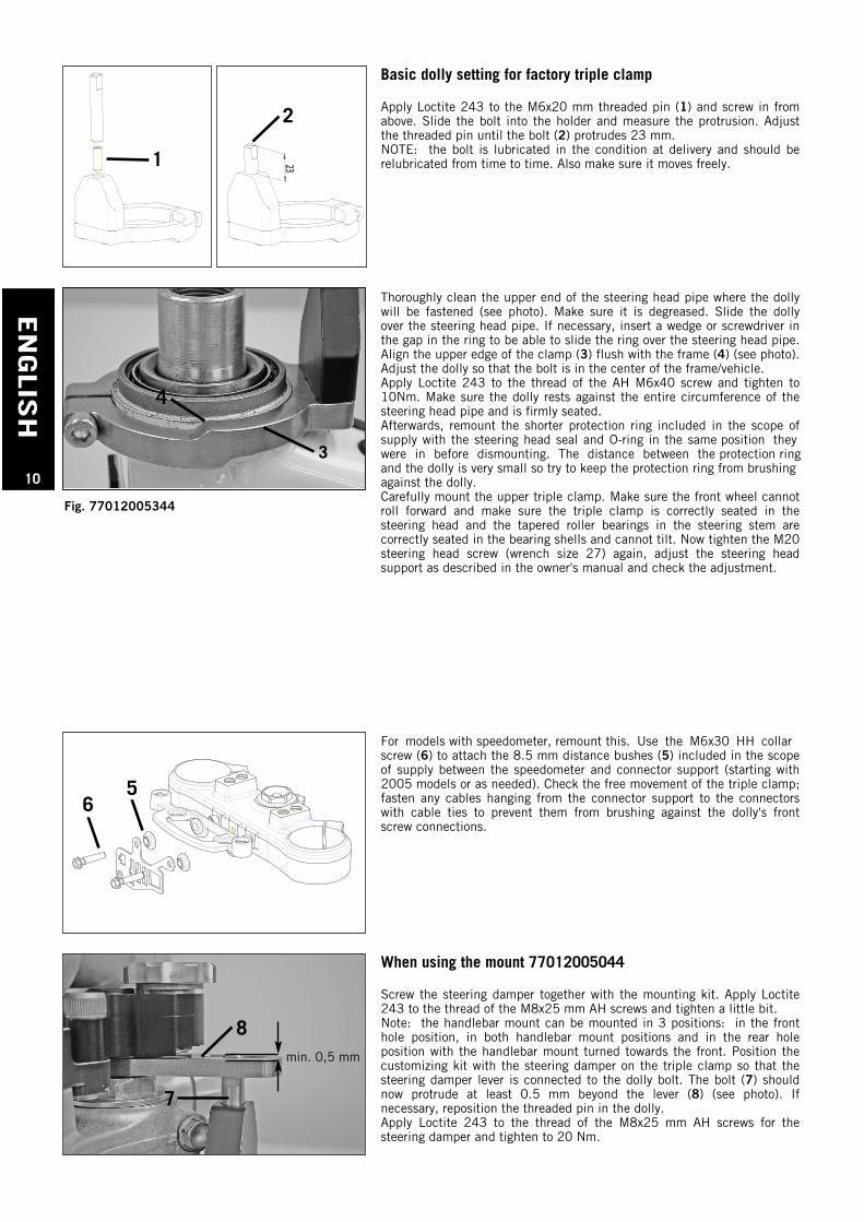
Basic dolly setting for factory triple clamp
Apply Loctite 243 to the M6x20 mm threaded pin (1) and screw in fromabove. Slide the bolt into the holder and measure the protrusion. Adjustthe threaded pin until the bolt (2) protrudes 23 mm.NOTE: the bolt is lubricated in the condition at delivery and should berelubricated from time to time. Also make sure it moves freely.23231
2
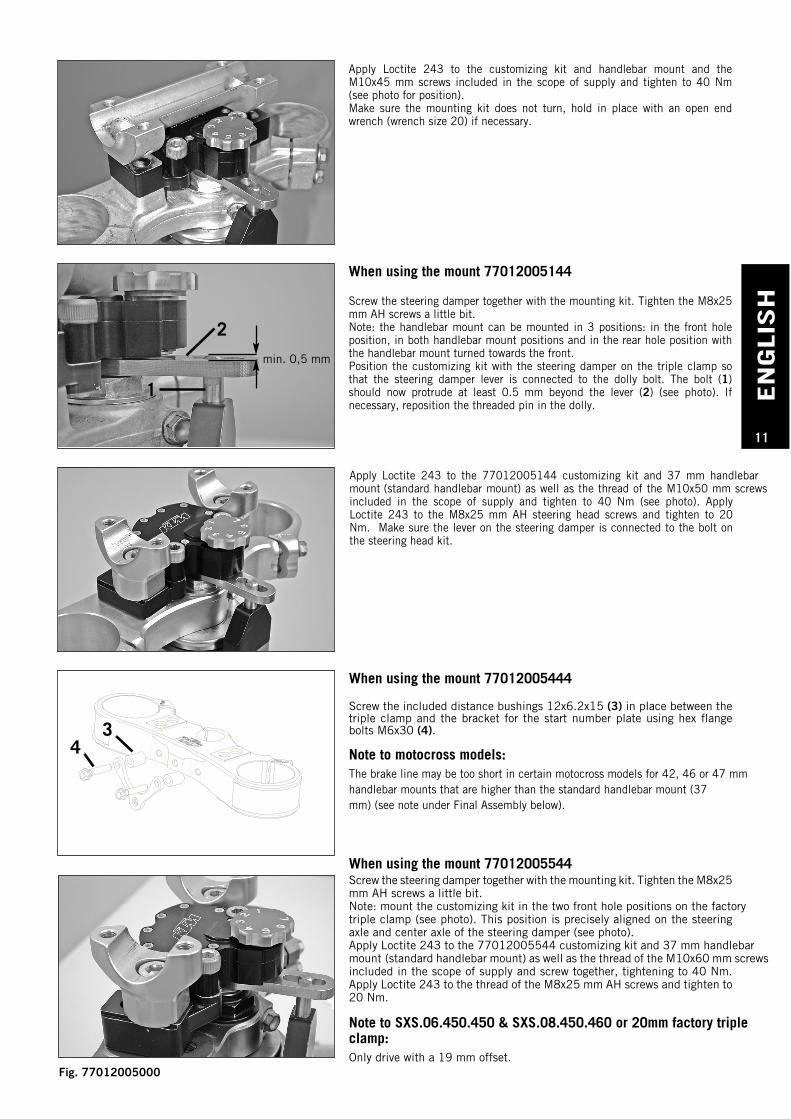
Thoroughly clean the upper end of the steering head pipe where the dollywill be fastened (see photo). Make sure it is degreased. Slide the dollyover the steering head pipe. If necessary, insert a wedge or screwdriver inthe gap in the ring to be able to slide the ring over the steering head pipe.Align the upper edge of the clamp (3) flush with the frame (4) (see photo).Adjust the dolly so that the bolt is in the center of the frame/vehicle.Apply Loctite 243 to the thread of the AH M6x40 screw and tighten to10Nm. Make sure the dolly rests against the entire circumference of thesteering head pipe and is firmly seated. Afterwards, remount the shorter protection ring included in the scope ofsupply with the steering head seal and O-ring in the same position they were in before dismounting. The distance between the protection ring and the dolly is very small so try to keep the protection ring from brushing against the dolly. Carefully mount the upper triple clamp. Make sure the front wheel cannotroll forward and make sure the triple clamp is correctly seated in thesteering head and the tapered roller bearings in the steering stem arecorrectly seated in the bearing shells and cannot tilt. Now tighten the M20steering head screw (wrench size 27) again, adjust the steering headsupport as described in the owner's manual and check the adjustment.
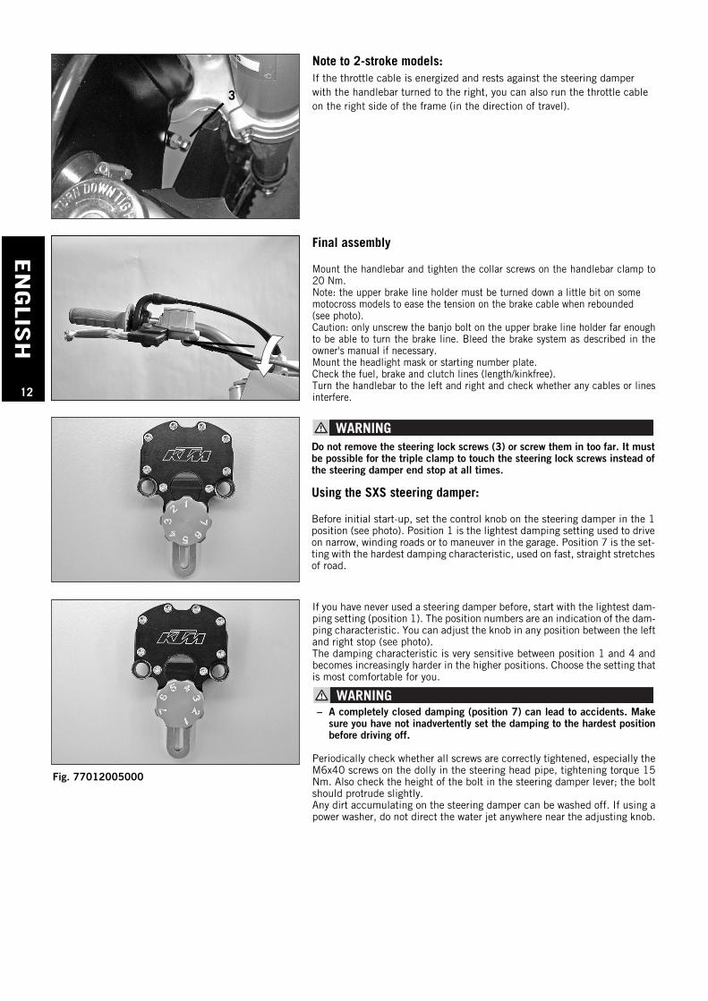
For models with speedometer, remount this. Use the M6x30 HH collarscrew (6) to attach the 8.5 mm distance bushes (5) included in the scopeof supply between the speedometer and connector support (starting with2005 models or as needed). Check the free movement of the triple clamp;fasten any cables hanging from the connector support to the connectorswith cable ties to prevent them from brushing against the dolly's frontscrew connections.
56
When using the mount 77012005044
Screw the steering damper together with the mounting kit. Apply Loctite243 to the thread of the M8x25 mm AH screws and tighten a little bit. Note: the handlebar mount can be mounted in 3 positions: in the fronthole position, in both handlebar mount positions and in the rear holeposition with the handlebar mount turned towards the front. Position thecustomizing kit with the steering damper on the triple clamp so that thesteering damper lever is connected to the dolly bolt. The bolt (7) shouldnow protrude at least 0.5 mm beyond the lever (8) (see photo). Ifnecessary, reposition the threaded pin in the dolly.Apply Loctite 243 to the thread of the M8x25 mm AH screws for thesteering damper and tighten to 20 Nm.
8
7
3
4
min. 0,5 mm
Fig. 77012005344
EN
GLI
SH
11
When using the mount 77012005144
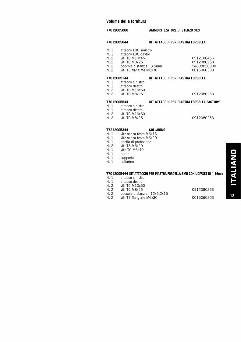
Screw the steering damper together with the mounting kit. Tighten the M8x25mm AH screws a little bit. Note: the handlebar mount can be mounted in 3 positions: in the front holeposition, in both handlebar mount positions and in the rear hole position withthe handlebar mount turned towards the front. Position the customizing kit with the steering damper on the triple clamp sothat the steering damper lever is connected to the dolly bolt. The bolt (1)should now protrude at least 0.5 mm beyond the lever (2) (see photo). Ifnecessary, reposition the threaded pin in the dolly.
When using the mount 77012005544Screw the steering damper together with the mounting kit. Tighten the M8x25mm AH screws a little bit. Note: mount the customizing kit in the two front hole positions on the factorytriple clamp (see photo). This position is precisely aligned on the steeringaxle and center axle of the steering damper (see photo).Apply Loctite 243 to the 77012005544 customizing kit and 37 mm handlebar mount (standard handlebar mount) as well as the thread of the M10x60 mm screwsincluded in the scope of supply and screw together, tightening to 40 Nm.Apply Loctite 243 to the thread of the M8x25 mm AH screws and tighten to20 Nm.
Note to SXS.06.450.450 & SXS.08.450.460 or 20mm factory tripleclamp:Only drive with a 19 mm offset.
Apply Loctite 243 to the customizing kit and handlebar mount and theM10x45 mm screws included in the scope of supply and tighten to 40 Nm(see photo for position).Make sure the mounting kit does not turn, hold in place with an open endwrench (wrench size 20) if necessary.
2
1
Apply Loctite 243 to the 77012005144 customizing kit and 37 mm handlebar mount (standard handlebar mount) as well as the thread of the M10x50 mm screwsincluded in the scope of supply and tighten to 40 Nm (see photo). ApplyLoctite 243 to the M8x25 mm AH steering head screws and tighten to 20Nm. Make sure the lever on the steering damper is connected to the bolt onthe steering head kit.
min. 0,5 mm
When using the mount 77012005444
Screw the included distance bushings 12x6.2x15 (3) in place between thetriple clamp and the bracket for the start number plate using hex flangebolts M6x30 (4).
Note to motocross models:The brake line may be too short in certain motocross models for 42, 46 or 47 mmhandlebar mounts that are higher than the standard handlebar mount (37mm) (see note under Final Assembly below).
34
Fig. 77012005000
EN
GLIS
H
12
Final assembly
Mount the handlebar and tighten the collar screws on the handlebar clamp to20 Nm. Note: the upper brake line holder must be turned down a little bit on some motocross models to ease the tension on the brake cable when rebounded (see photo). Caution: only unscrew the banjo bolt on the upper brake line holder far enoughto be able to turn the brake line. Bleed the brake system as described in theowner's manual if necessary. Mount the headlight mask or starting number plate. Check the fuel, brake and clutch lines (length/kinkfree). Turn the handlebar to the left and right and check whether any cables or linesinterfere.
If you have never used a steering damper before, start with the lightest dam-ping setting (position 1). The position numbers are an indication of the dam-ping characteristic. You can adjust the knob in any position between the leftand right stop (see photo).The damping characteristic is very sensitive between position 1 and 4 andbecomes increasingly harder in the higher positions. Choose the setting thatis most comfortable for you.
– A completely closed damping (position 7) can lead to accidents. Makesure you have not inadvertently set the damping to the hardest positionbefore driving off.
Periodically check whether all screws are correctly tightened, especially theM6x40 screws on the dolly in the steering head pipe, tightening torque 15Nm. Also check the height of the bolt in the steering damper lever; the boltshould protrude slightly.Any dirt accumulating on the steering damper can be washed off. If using apower washer, do not direct the water jet anywhere near the adjusting knob.
Do not remove the steering lock screws (3) or screw them in too far. It mustbe possible for the triple clamp to touch the steering lock screws instead ofthe steering damper end stop at all times.
Using the SXS steering damper:
Before initial start-up, set the control knob on the steering damper in the 1position (see photo). Position 1 is the lightest damping setting used to driveon narrow, winding roads or to maneuver in the garage. Position 7 is the set-ting with the hardest damping characteristic, used on fast, straight stretchesof road.
Note to 2-stroke models:If the throttle cable is energized and rests against the steering damperwith the handlebar turned to the right, you can also run the throttle cableon the right side of the frame (in the direction of travel).
3
Fig. 77012005000
ITALI
AN
O
13
Volume della fornitura
77012005000 AMMORTIZZATORE DI STERZO SXS
77012005044 KIT ATTACCHI PER PIASTRA FORCELLA
N. 1 attacco EXC sinistroN. 1 attacco EXC destroN. 2 viti TC M10x45 0912100456N. 2 viti TC M8x25 0912080253N. 2 boccole distanziali 8.5mm 54808020000N. 2 viti TE flangiate M6x30 0015060303
77012005144 KIT ATTACCHI PER PIASTRA FORCELLA N. 1 attacco sinistroN. 1 attacco destroN. 2 viti TC M10x50N. 2 viti TC M8x25 0912080253
77012005544 KIT ATTACCHI PER PIASTRA FORCELLA FACTORYN. 1 attacco sinistroN. 1 attacco destroN. 2 viti TC M10x60N. 2 viti TC M8x25 0912080253
77212905344 COLLARINON. 1 vite senza testa M6x16N. 1 vite senza testa M6x20N. 1 anello di protezioneN. 2 viti TS M6x20N. 1 vite TC M6x40N. 1 pernoN. 1 supportoN. 1 collarino
77012005444 KIT ATTACCHI PER PIASTRA FORCELLA SMR CON L’OFFSET DI 4-16mmN. 1 attacco sinistroN. 1 attacco destroN. 2 viti TC M10x50N. 2 viti TC M8x25 0912080253N. 2 boccole distanziali 12x6,2x15N. 2 viti TE flangiate M6x30 0015060303
ITALIA
NO
14
Avvertenza per l'ammortizzatore di sterzo SXS:Può capitare che allo stato di consegna l'ammortizzatore di sterzo sialeggermente "oleoso". Ciò non significa che l'ammortizzatore di sterzoabbia un difetto di tenuta, ma è dovuto al suo riempimento in bagnod'olio. Questi residui d'olio possono essere rimossi con un panno!
Istruzioni di montaggio:
Pulire la motocicletta e metterla su un cavalletto di montaggio adattoin maniera che il peso della moto sia spostato sulla ruota anteriore e fissare ulteriormente la ruota anteriore per impedire che ruoti in avanti.Attenzione: quando è stata smontata la piastra forcella superiore, è moltofacile che la forcella scivoli in basso!
Togliere la mascherina faro ossia il portanumero e tachimetro.
Svitare le viti dei cavallotti serramanubrio e togliere il manubrio.
Bloccare la ruota anteriore in modo che non possa ruotare in avanti.
Allentare le viti di serraggio della piastra forcella superiore e svitare la vitetesta sterzo M20.Smontare la piastra forcella superiore aiutandosi, se necessario, con unmartello di plastica. Far attenzione a non angolare la piastra forcella allosmontaggio.Togliere l'O-ring, l'anello di protezione e la guarnizionetesta sterzo, se presente. Attenzione: più tardi l'O-ring e la guarnizione devono essere rimontati -tener a mente la posizione di montaggio!
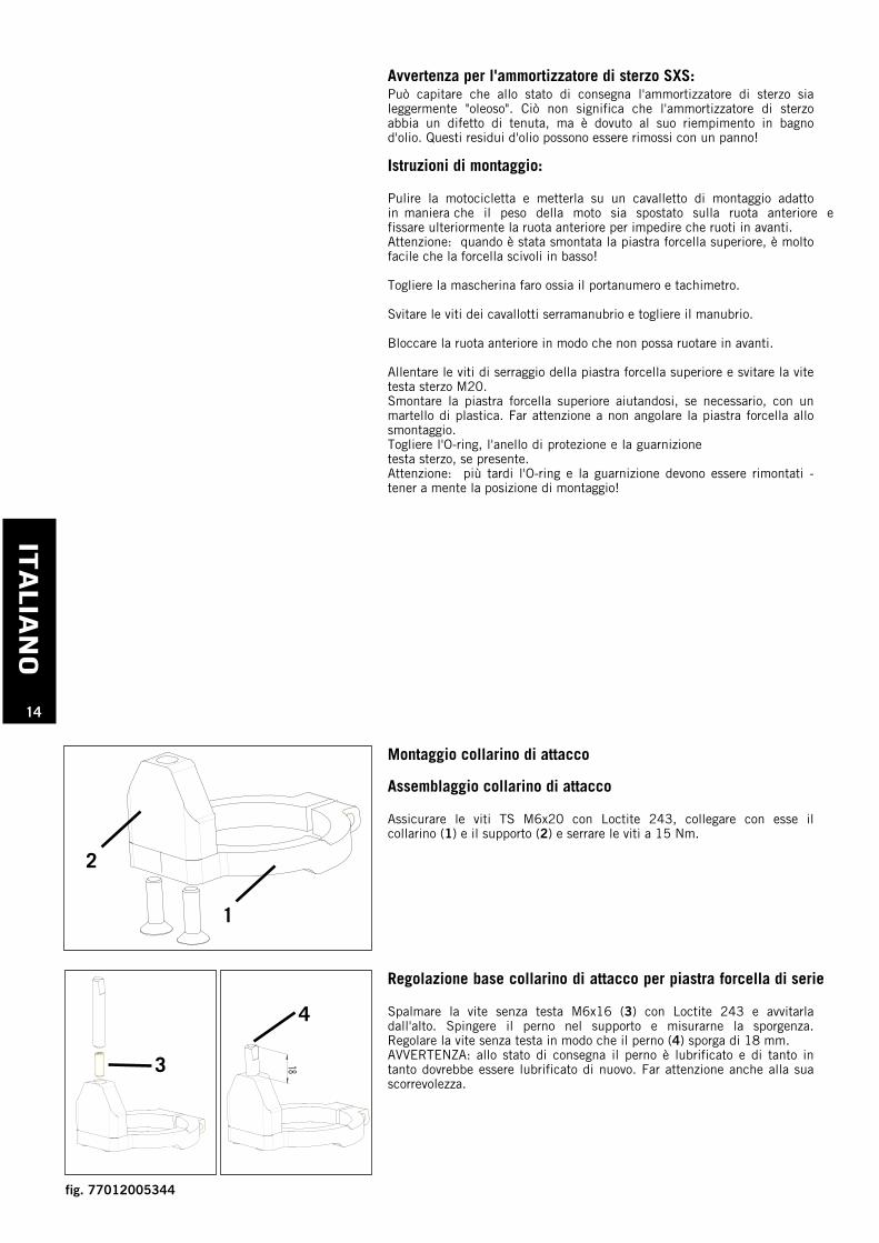
Montaggio collarino di attacco
Assemblaggio collarino di attacco
Assicurare le viti TS M6x20 con Loctite 243, collegare con esse ilcollarino (1) e il supporto (2) e serrare le viti a 15 Nm.
1
2
Regolazione base collarino di attacco per piastra forcella di serie
Spalmare la vite senza testa M6x16 (3) con Loctite 243 e avvitarladall'alto. Spingere il perno nel supporto e misurarne la sporgenza.Regolare la vite senza testa in modo che il perno (4) sporga di 18 mm.AVVERTENZA: allo stato di consegna il perno è lubrificato e di tanto intanto dovrebbe essere lubrificato di nuovo. Far attenzione anche alla suascorrevolezza.
183
4
fig. 77012005344
ITALI
AN
O
15
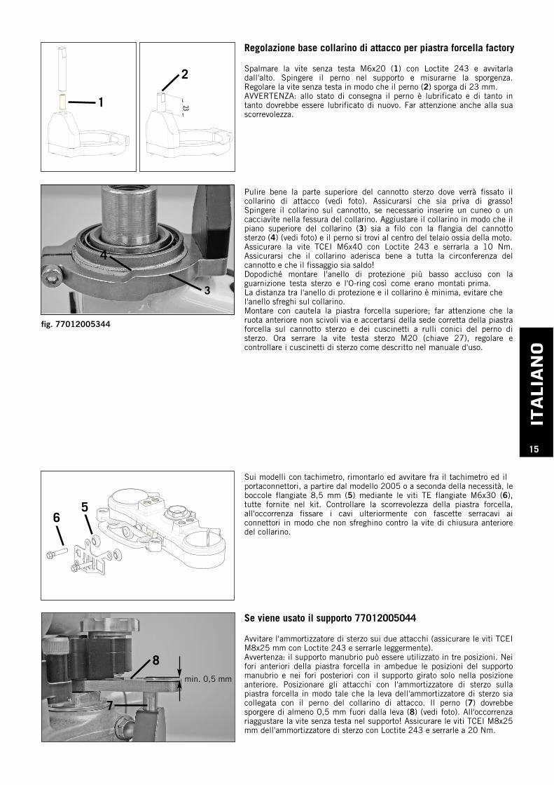
Regolazione base collarino di attacco per piastra forcella factory
Spalmare la vite senza testa M6x20 (1) con Loctite 243 e avvitarladall'alto. Spingere il perno nel supporto e misurarne la sporgenza.Regolare la vite senza testa in modo che il perno (2) sporga di 23 mm.AVVERTENZA: allo stato di consegna il perno è lubrificato e di tanto intanto dovrebbe essere lubrificato di nuovo. Far attenzione anche alla suascorrevolezza.
23231
2
Pulire bene la parte superiore del cannotto sterzo dove verrà fissato ilcollarino di attacco (vedi foto). Assicurarsi che sia priva di grasso!Spingere il collarino sul cannotto, se necessario inserire un cuneo o uncacciavite nella fessura del collarino. Aggiustare il collarino in modo che ilpiano superiore del collarino (3) sia a filo con la flangia del cannottosterzo (4) (vedi foto) e il perno si trovi al centro del telaio ossia della moto.Assicurare la vite TCEI M6x40 con Loctite 243 e serrarla a 10 Nm.Assicurarsi che il collarino aderisca bene a tutta la circonferenza delcannotto e che il fissaggio sia saldo!Dopodiché montare l'anello di protezione più basso accluso con laguarnizione testa sterzo e l'O-ring così come erano montati prima. La distanza tra l'anello di protezione e il collarino è minima, evitare che l'anello sfreghi sul collarino.Montare con cautela la piastra forcella superiore; far attenzione che laruota anteriore non scivoli via e accertarsi della sede corretta della piastraforcella sul cannotto sterzo e dei cuscinetti a rulli conici del perno disterzo. Ora serrare la vite testa sterzo M20 (chiave 27), regolare econtrollare i cuscinetti di sterzo come descritto nel manuale d'uso.
Sui modelli con tachimetro, rimontarlo ed avvitare fra il tachimetro ed ilportaconnettori, a partire dal modello 2005 o a seconda della necessità, leboccole flangiate 8,5 mm (5) mediante le viti TE flangiate M6x30 (6),tutte fornite nel kit. Controllare la scorrevolezza della piastra forcella,all'occorrenza fissare i cavi ulteriormente con fascette serracavi aiconnettori in modo che non sfreghino contro la vite di chiusura anterioredel collarino.
56
Se viene usato il supporto 77012005044
Avvitare l'ammortizzatore di sterzo sui due attacchi (assicurare le viti TCEIM8x25 mm con Loctite 243 e serrarle leggermente).Avvertenza: il supporto manubrio può essere utilizzato in tre posizioni. Neifori anteriori della piastra forcella in ambedue le posizioni del supportomanubrio e nei fori posteriori con il supporto girato solo nella posizioneanteriore. Posizionare gli attacchi con l'ammortizzatore di sterzo sullapiastra forcella in modo tale che la leva dell'ammortizzatore di sterzo siacollegata con il perno del collarino di attacco. Il perno (7) dovrebbesporgere di almeno 0,5 mm fuori dalla leva (8) (vedi foto). All'occorrenzariaggustare la vite senza testa nel supporto! Assicurare le viti TCEI M8x25mm dell'ammortizzatore di sterzo con Loctite 243 e serrarle a 20 Nm.
8
7
3
4
min. 0,5 mm
fig. 77012005344
ITALIA
NO
16
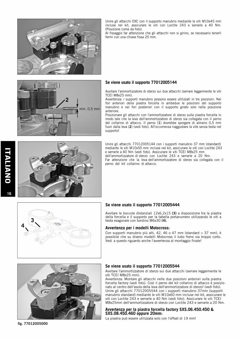
Se viene usato il supporto 77012005144
Avvitare l'ammortizzatore di sterzo sui due attacchi (serrare leggermente le vitiTCEI M8x25 mm).Avvertenza: i supporti manubrio possono essere utilizzati in tre posizioni. Neifori anteriori della piastra forcella in ambedue le posizioni del supportomanubrio e nei fori posteriori con il supporto girato solo nella posizioneanteriore.Posizionare gli attacchi con l'ammortizzatore di sterzo sulla piastra forcella inmodo tale che la leva dell'ammortizzatore di sterzo sia collegata con il pernodel collarino di attacco. Il perno (1) dovrebbe sporgere di almeno 0,5 mmfuori dalla leva (2) (vedi foto). All'occorrenza riaggustare la vite senza testa nelsupporto!
Se viene usato il supporto 77012005544Avvitare l'ammortizzatore di sterzo sui due attacchi (serrare leggermente leviti TCEI M8x25 mm).Avvertenza: Montare gli attacchi nelle due posizioni anteriori sulla piastraforcella factory (vedi foto). Così il perno del kit collarino di attacco è posizio-nato al centro dell'asola della leva dell'ammortizzatore di sterzo! (vedi foto).Unire gli attacchi 77012005544 con i supporti manubrio 37mm (supporti manubrio standard) mediante le viti M10x60 mm incluse nel kit, assicurare le viti con Loctite 243 e serrarle a 40 Nm (vedi foto). Assicurare le viti TCEI M8x25mm dell'ammortizzatore di sterzo con Loctite 243 e serrarle a 20 Nm.
Avvertenza per la piastra forcella factory SXS.06.450.450 &SXS.08.450.460 oppure 20mm:La piastra può essere utilizzata solo con l'offset di 19 mm!
Unire gli attacchi EXC con il supporto manubrio mediante le viti M10x45 mmincluse nel kit, assicurare le viti con Loctite 243 e serrarle a 40 Nm.(Posizione come da foto).Al fissaggio far attenzione che gli attacchi non si girino, se necessario tenerlifermi con una chiave fissa 20 mm.
2
1
Unire gli attacchi 77012005144 con i supporti manubrio 37 mm (standard) mediante le viti M10x50 mm incluse nel kit, assicurare le viti con Loctite 243 e serrarle a 40 Nm (vedi foto). Assicurare le viti TCEI M8x25 mm dell'ammortizzatore di sterzo con Loctite 243 e serrarle a 20 Nm. Far attenzione che la leva dell'ammortizzatore di sterzo sia collegata con il perno del kit collarino di attacco.
min. 0,5 mm
Se viene usato il supporto 77012005444
Avvitare le boccole distanziali 12x6,2x15 (3) a disposizione tra la piastradella forcella e il supporto per la tabella portanumero utilizzando le viti atesta esagonale con bordino M6x30 (4).
Avvertenza per i modelli Motocross:Con supporti manubrio più alti, 42, 46 o 47 mm (standard = 37 mm), èpossibile che su diversi modelli Motocross il tubo freno sia troppo corto. Vedi a questo riguardo anche l'avvertenza al montaggio finale!
34
fig. 77012005000
ITALI
AN
O
17
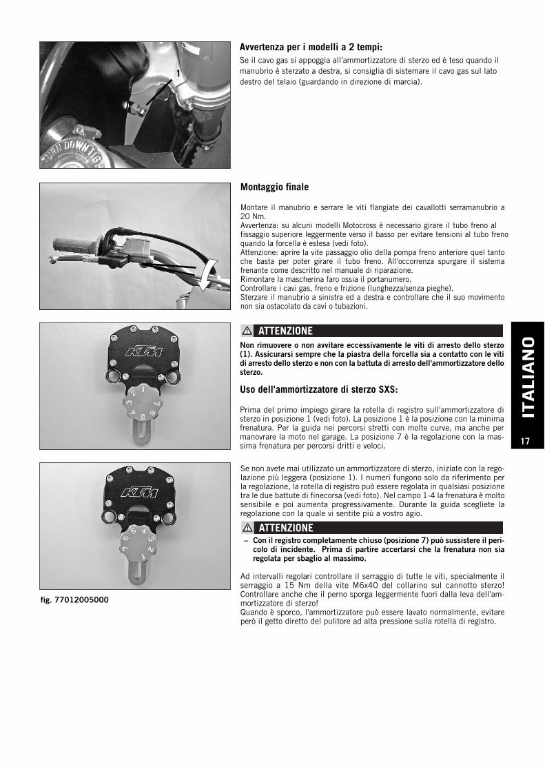
Montaggio finale
Montare il manubrio e serrare le viti flangiate dei cavallotti serramanubrio a20 Nm.Avvertenza: su alcuni modelli Motocross è necessario girare il tubo freno al fissaggio superiore leggermente verso il basso per evitare tensioni al tubo freno quando la forcella è estesa (vedi foto).Attenzione: aprire la vite passaggio olio della pompa freno anteriore quel tantoche basta per poter girare il tubo freno. All'occorrenza spurgare il sistemafrenante come descritto nel manuale di riparazione.Rimontare la mascherina faro ossia il portanumero.Controllare i cavi gas, freno e frizione (lunghezza/senza pieghe).Sterzare il manubrio a sinistra ed a destra e controllare che il suo movimentonon sia ostacolato da cavi o tubazioni.
Se non avete mai utilizzato un ammortizzatore di sterzo, iniziate con la rego-lazione più leggera (posizione 1). I numeri fungono solo da riferimento perla regolazione, la rotella di registro può essere regolata in qualsiasi posizionetra le due battute di finecorsa (vedi foto). Nel campo 1-4 la frenatura è moltosensibile e poi aumenta progressivamente. Durante la guida scegliete laregolazione con la quale vi sentite più a vostro agio.
– Con il registro completamente chiuso (posizione 7) può sussistere il peri-colo di incidente. Prima di partire accertarsi che la frenatura non siaregolata per sbaglio al massimo.
Ad intervalli regolari controllare il serraggio di tutte le viti, specialmente ilserraggio a 15 Nm della vite M6x40 del collarino sul cannotto sterzo!Controllare anche che il perno sporga leggermente fuori dalla leva dell'am-mortizzatore di sterzo!Quando è sporco, l'ammortizzatore può essere lavato normalmente, evitareperò il getto diretto del pulitore ad alta pressione sulla rotella di registro.
Non rimuovere o non avvitare eccessivamente le viti di arresto dello sterzo(1). Assicurarsi sempre che la piastra della forcella sia a contatto con le vitidi arresto dello sterzo e non con la battuta di arresto dell'ammortizzatore dellosterzo.
Uso dell'ammortizzatore di sterzo SXS:
Prima del primo impiego girare la rotella di registro sull'ammortizzatore disterzo in posizione 1 (vedi foto). La posizione 1 è la posizione con la minimafrenatura. Per la guida nei percorsi stretti con molte curve, ma anche permanovrare la moto nel garage. La posizione 7 è la regolazione con la mas-sima frenatura per percorsi dritti e veloci.
1
Avvertenza per i modelli a 2 tempi:Se il cavo gas si appoggia all'ammortizzatore di sterzo ed è teso quando ilmanubrio è sterzato a destra, si consiglia di sistemare il cavo gas sul latodestro del telaio (guardando in direzione di marcia).
fig. 77012005000
FRAN
CAIS
18
Kit de livraison
77012005000 AMORTISSEUR DE DIRECTION
77012005044 FIXATION POUR TÉ DE FOURCHE
1 support d'amortisseur EXC gauche1 support d'amortisseur EXC droit2 vis à tête cylindrique M10x45 09121004562 vis à tête cylindrique M8x25 09120802532 entretoises 8,5 mm 548080200002 vis six pans à épaulement M6x30 0015060303
77012005144 FIXATION POUR TÉ DE FOURCHE 1 support d'amortisseur gauche1 support d'amortisseur droit2 vis à tête cylindrique M10x502 vis à tête cylindrique M8x25 0912080253
77012005544 FIXATION POUR TÉ DE FOURCHE FACTORY1 support d'amortisseur gauche1 support d'amortisseur droit2 vis à tête cylindrique M10x602 vis à tête cylindrique M8x25 0912080253
77212905344 FIXATION SUR COLONNE DE DIRECTION1 goujon M6x161 goujon M6x201 bague de protection2 vis à tête fraisée M6x201 vis à tête cylindrique M6x401 doigt1 support1 collier
77012005444 FIXATION POUR TÉ DE FOURCHE SMR DÉPORT 14-16mm1 support d'amortisseur gauche1 support d'amortisseur droit2 vis à tête cylindrique M10x502 vis à tête cylindrique M8x25 09120802532 entretoises 12x6,2x152 vis six pans à épaulement M6x30 0015060303
FRAN
CAIS
19
Remarque concernant l'amortisseur de direction SXS:Il peut arriver que l'amortisseur, quand il est livré, soit un peu gras. Celane signifie nullement qu'il ait une fuite. C'est simplement en rapport avecle mode de remplissage en bain. Il suffit d'essuyer ces traces d'huile avecun chiffon.
Notice de montage:
La moto ayant été nettoyée, la béquiller sur une béquille appropriée demanière à ce que le poids soit sur la roue avant. Fixer également la roueavant de sorte que la machine ne puisse pas avancer.
Attention : Quand on retire le té supérieur de fourche, celle-ci peutfacilement glisser ou s'enfoncer. Selon le cas, retirer le capotage de phare ou la plaque de course, et tachymètre. Enlever les vis de fixation du guidon et déposer celui-ci. Fixer la roue avant de manière à ce qu'elle ne puisse pas se dérober. Desserrer les vis de fixation du té supérieur de fourche et retirer la visM20 de la colonne. Déposer le té supérieur en s'aidant, si besoin est, dequelques coups de maillet en caoutchouc. Ce faisant, faire attention à ceque le té ne se mette pas de travers.Retirer le joint torique, la bague de protection et le cache de la colonne,le cas échéant. Attention : Ces éléments seront nécessaires lors du remontage. Repérer laposition.
Montage de la fixation sur colonne de direction
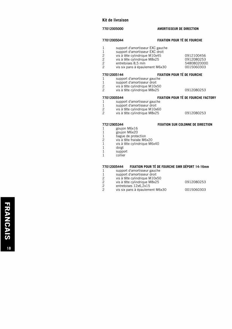
Assemblage de la fixation
Assembler le collier (1) et le support (2) au moyen des vis à tête fraiséeM6x20. Freiner à la loctite 243 et serrer à 15 Nm.
1
2
Réglage de base pour la fixation té de fourche série
Mettre de la loctite 243 sur le goujon M6x16 mm (3) et le visser par ledessus. Enfiler le doigt dans la fixation et mesurer de combien il dépasse.Visser ou dévisser le goujon pour que le doigt (4) dépasse de 18 mm.Remarque : Quand il est livré, le doigt est graissé. Il faudra remettre de lagraisse de temps à autre. Il faut faire en sorte qu'il n'y ait pas de pointdur.
183
4
fig. 77012005344
FRAN
CAIS
20
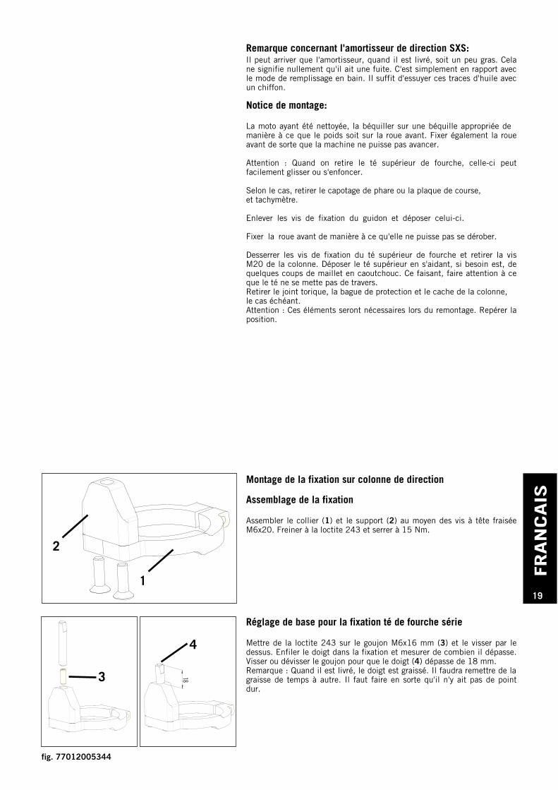
Réglage de base pour la fixation té de fourche factory
Mettre de la loctite 243 sur le goujon M6x20 mm (1) et le visser par ledessus. Enfiler le doigt dans la fixation et mesurer de combien il dépasse.Visser ou dévisser le goujon pour que le doigt (2) dépasse de 23 mm.Remarque : Quand il est livré, le doigt est graissé. Il faudra remettre de lagraisse de temps à autre. Il faut faire en sorte qu'il n'y ait pas de pointdur.
23231
2
Bien nettoyer la partie supérieure de la colonne de direction, là où se metla fixation (voir illustration). Faire attention à ce qu'il n'y ait pas degraisse. Enfiler la fixation sur la colonne en mettant, si besoin est, un coinou un tournevis dans la fente pour écarter un peu de manière à pouvoirenfiler sans problème. Le bord supérieur du collier (3) doit affleurer avecla colonne (4) (voir illustration). Ajuster la fixation pour que le doigt soitdans l'axe de la moto.
Freiner la vis M6x40 à la loctite 243 et la serrer à 10 Nm. S'assurer quele contact entre la fixation et la colonne se fait sur tout le tour et que lafixation tient bien.
Puis mettre la bague de protection plus courte, qui fait partie du kit livré,ainsi que le cache et le joint torique. Tenir compte du repérage effectué au démontage. L'écartement entre la bague de protection et la fixation est faible. Veiller à ce qu'il n'y ait pas de frottement entre les deux.Monter le té supérieur de fourche avec précaution. Faire attention à ceque la roue avant ne se dérobe pas et veiller à ce que le té prenne bien saplace et que les roulements ne se mettent pas de travers. Serrer alors lavis M20 (clef de 27) et régler les roulements comme cela est indiqué dansle manuel d'utilisation.
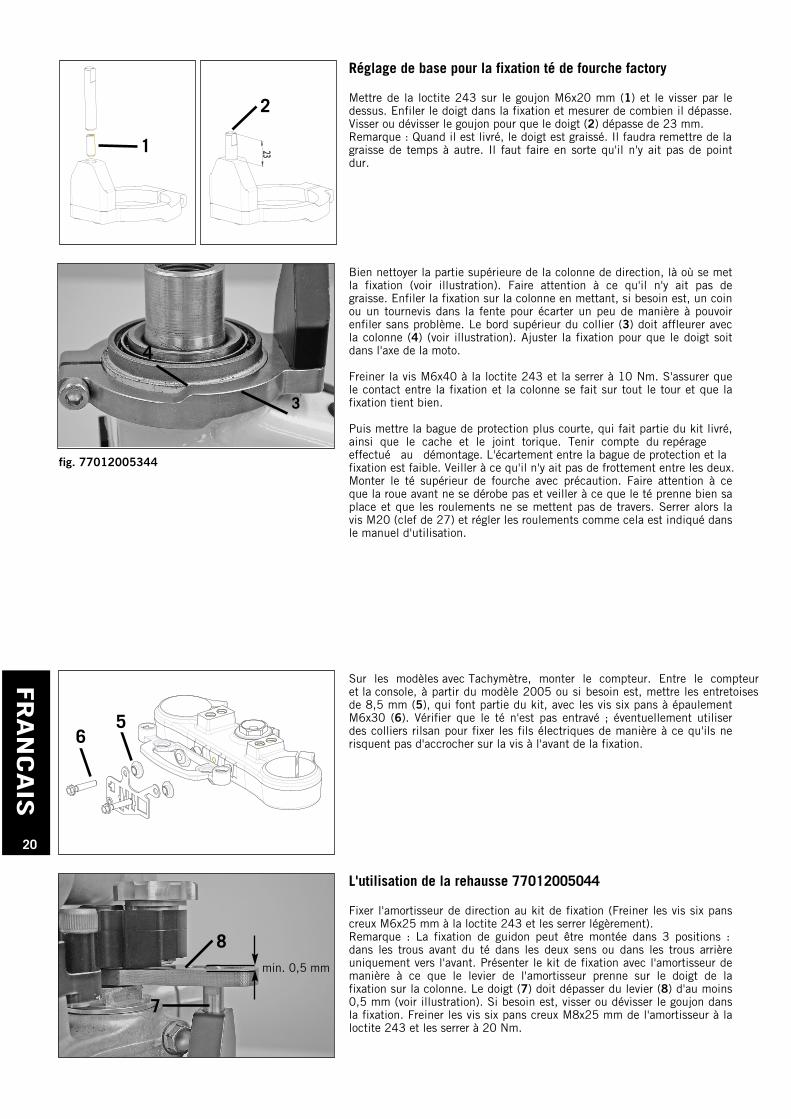
Sur les modèles avec Tachymètre, monter le compteur. Entre le compteur et la console, à partir du modèle 2005 ou si besoin est, mettre les entretoisesde 8,5 mm (5), qui font partie du kit, avec les vis six pans à épaulementM6x30 (6). Vérifier que le té n'est pas entravé ; éventuellement utiliserdes colliers rilsan pour fixer les fils électriques de manière à ce qu'ils nerisquent pas d'accrocher sur la vis à l'avant de la fixation.
56
L'utilisation de la rehausse 77012005044
Fixer l'amortisseur de direction au kit de fixation (Freiner les vis six panscreux M6x25 mm à la loctite 243 et les serrer légèrement).Remarque : La fixation de guidon peut être montée dans 3 positions :dans les trous avant du té dans les deux sens ou dans les trous arrièreuniquement vers l'avant. Présenter le kit de fixation avec l'amortisseur demanière à ce que le levier de l'amortisseur prenne sur le doigt de lafixation sur la colonne. Le doigt (7) doit dépasser du levier (8) d'au moins0,5 mm (voir illustration). Si besoin est, visser ou dévisser le goujon dansla fixation. Freiner les vis six pans creux M8x25 mm de l'amortisseur à laloctite 243 et les serrer à 20 Nm.
8
7
3
4
min. 0,5 mm
fig. 77012005344
FRAN
CAIS
21
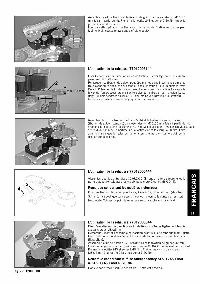
L'utilisation de la rehausse 77012005144
Fixer l'amortisseur de direction au kit de fixation. (Serrer légèrement les vis sixpans creux M8x25 mm).Remarque : La fixation de guidon peut être montée dans 3 positions : dans lestrous avant du té dans les deux sens ou dans les trous arrière uniquement versl'avant. Présenter le kit de fixation avec l'amortisseur de manière à ce que lelevier de l'amortisseur prenne sur le doigt de la fixation sur la colonne. Ledoigt (1) doit dépasser du levier (2) d'au moins 0,5 mm (voir illustration). Sibesoin est, visser ou dévisser le goujon dans la fixation.
L'utilisation de la rehausse 77012005544Fixer l'amortisseur de direction au kit de fixation. (Serrer légèrement les vissix pans creux M8x25 mm).Remarque : Monter l'ensemble en position avant sur le té fabrique (voir illustra-tion). Cela correspond exactement aux axes de l'amortisseur de direction (voirillustration).Assembler le kit de fixation 77012005544 et la fixation de guidon 37 mm (fixation de guidon standard) au moyen des vis M10x60 mm faisant partie du kit. Freiner à la loctite 243 et serrer à 40 Nm. Freiner les vis six pans creux M8x25 mm à la loctite 243 et les serrer à 20 Nm.
Remarque concernant le té de fourche factory SXS.06.450.450 & SXS.08.450.460 ou 20 mm:Dans le cas présent seul le déport de 19 mm est possible.
Assembler le kit de fixation et la fixation de guidon au moyen des vis M10x45mm faisant partie du kit. Freiner à la loctite 243 et serrer à 40 Nm (pour laposition, voir l'illustration).Lors de cette opération, veiller à ce que le kit de fixation ne tourne pas.Maintenir si nécessaire avec une clef plate de 20.
2
1
Assembler le kit de fixation 77012005144 et la fixation de guidon 37 mm (fixation de guidon standard) au moyen des vis M10x50 mm faisant partie du kit. Freiner à la loctite 243 et serrer à 40 Nm (voir illustration). Freiner les vis six panscreux M8x25 mm de l'amortisseur à la loctite 243 et les serrer à 20 Nm. Faireattention à ce que le levier de l'amortisseur prenne bien sur le doigt de lafixation sur la colonne.
min. 0,5 mm
L'utilisation de la rehausse 77012005444
Visser les douilles-entretoises 12x6,2x15 (3) entre le té de fourche et leporte-plaque frontale avec les vis six-pans creux à collet M6x30 (4).
Remarque concernant les modèles motocross:Pour une fixation de guidon plus haute, à savoir 42, 46 ou 47 mm (standard =37 mm), il se peut que sur certains modèles motocross la durite de frein soit trop courte. Voir sur ce point la remarque au paragraphe montage final.
34
fig. 77012005000
FRAN
CAIS
22
Montage final
Monter le guidon et serrer les vis à épaulement des pontets à 20 Nm.Remarque : Sur certains modèles motocross la fixation haute de la durite de frein doit être un peu tournée vers le bas de manière à ce qu'il n'y ait pas de contrainte sur la durite quand la fourche est en extension. (Voir illustration).Remarque : Dévisser la vis creuse en haut de la durite juste suffisammentpour pouvoir tourner cette dernière. Si besoin est, purger le circuit selon lesindications du manuel d'utilisation.Remonter le capotage de phare ou la plaque de course.Vérifier câble ou durite pour ce qui est de la poignée de gaz, du frein et del'embrayage (bonne longueur, pas de croc). Braquer le guidon à fond à droiteet à gauche et vérifier que les fils, câbles et durites restent libres.
Si l'on n'a jamais utilisé d'amortisseur de direction, on commencera avecl'amortissement minimum (position 1). Les chiffres donnent une idée de rég-lage, mais on peut mettre le bouton dans n'importe quelle position entre lesdeux butées extrêmes (voir illustration). L'amortissement se fait en douceursur la plage 1 à 4, puis devient ensuite de plus en plus fort. Choisir le rég-lage sur lequel on se sent le mieux.
– En position complètement fermée (position 7), dans des conditions par-ticulières il peut y avoir un certain danger. S'assurer avant de démarrerque l'amortissement n'a pas été mis par erreur dans cette position.
S'assurer périodiquement du serrage de tous les assemblages, en particulierde la vis M6x40 sur la colonne (couple de serrage 15 Nm). Vérifier aussi quele doigt qui prend dans le levier de l'amortisseur est à la bonne hauteur. Ildoit dépasser légèrement.Quand la moto est sale, on peut procéder normalement au lavage. Il faut tou-tefois éviter de diriger le jet du nettoyeur haute pression sur la vis de rég-lage de l'amortisseur.
Les vis de butée de braquage (1) ne doivent être ni enlevées ni vissées tropprofondément. Il faut toujours que le té de fourche bute contre ces vis etnon contre la butée de l'amortisseur de direction.
Utilisation de l'amortisseur SXS
Avant la première utilisation, tourner le bouton de réglage de l'amortisseursur la position 1 (voir illustration), ce qui correspond à l'amortissement mini-mum. C'est la position pour quand on roule sur un terrain avec beaucoup devirages étroits et pour manœuvrer dans le garage. La position 7 correspondà l'amortissement maximum, un réglage pour les terrains avec de longueslignes droites rapides.
Remarque concernant les modèles deux-temps:Si le câble de gaz touche à l'amortisseur de direction quand le guidon esttourné vers la droite et se trouve alors tendu, il est possible de faire passerce câble sur la droite du cadre (dans le sens de la marche).
1
fig. 77012005000
ESPAN
OL
23
Volumen de suministro
77012005000 AMORTIGUADOR DE LA DIRECCIÓN SXS
77012005044 SOPORTE PARA LA TIJA
1 soporte izquierdo del amortiguador de la dirección EXC1 soporte derecho del amortiguador de la dirección EXC2 tornillos del cilindro M10x45 mm 09121004562 tornillos del cilindro M8x25 mm 09120802532 casquillos distanciadores 8,5 mm 548080200002 tornillos collar hexagonales M6x30 mm 0015060303
77012005144 SOPORTE PARA LA TIJA 1 soporte izquierdo del amortiguador de la dirección 1 soporte derecho del amortiguador de la dirección 2 tornillos del cilindro M10x50 mm2 tornillos del cilindro M8x25 mm 0912080253
77012005544 SOPORTE PARA LA TIJA FACTORY1 soporte izquierdo del amortiguador de la dirección1 soporte derecho del amortiguador de la dirección 2 tornillos del cilindro M10x60 mm2 tornillos del cilindro M8x25 mm 0912080253
77212905344 CONTRASOPORTE DEL AMORTIGUADOR DE LA DIRECCIÓN1 espárrago roscado M6x16 mm1 espárrago roscado M6x20 mm1 anillo de seguridad2 tornillos de cabeza rebajada M6x20 mm1 tornillo del cilindro M6x401 bulón del amortiguador de la dirección1 soporte del amortiguador de la dirección1 abrazadera del amortiguador de la dirección
77012005444 SOPORTE PARA LA TIJA SMR CON UN AJUSTE DE 14-16mm1 soporte izquierdo del amortiguador de la dirección1 soporte derecho del amortiguador de la dirección2 tornillos del cilindro M10x50 mm2 tornillos del cilindro M8x25 mm 09120802532 casquillos distanciadores 12x6,2x152 tornillos collar hexagonales M6x30 0015060303
ESPAN
OL
24
Advertencia para el amortiguador de la dirección SXS:Puede ser que el amortiguador en el estado de suministro sea ligeramente"aceitoso". Esto no significa que el amortiguador esté permeable, sino queestá relacionado solamente con el llenado en el baño de aceite; ¡estosrestos de aceite puede eliminarlos con un trapo!
Instrucciones para el montaje
Levantar la motocicleta limpia en un caballete de montaje adecuado de manera tal que el peso de la motocicleta quede en la rueda delantera, fijar la rueda delantera adicionalmente para que no pueda rodar hacia delante.Atención: ¡Si está retirada la tija superior puede ocurrir fácilmente undeslizamiento y/o la inmersión de la horquilla hacia abajo!
Quitar la placa portafaros y/o la placa para el número de competición, y el
velocímetro.
Retirar los tornillos de las bridas del manillar y quitar el manillar.
Fijar la rueda delantera de forma tal que no pueda rodar hacia adelante.
Aflojar los tornillos de fijación de la tija superior y desatornillar el tornillode la pipa de dirección M20 (ancho de llave 27).Desmontar la tija inferior, si fuera necesario ayudarse ligeramente con unmartillo de goma. Tener cuidado de que la tija no se atasque.Quitar el aro tórico, el anillo de seguridad y la junta de la pipa de dirección,si está disponible. Atención: ¡Se necesita más tarde para el ensamblaje - acordarse de laposición de montaje!
Montaje del contrasoporte
Ensamblar el contrasoporte
Asegurar los tornillos de cabeza rebajada M6x20 con Loctite 243,atornillarlos además con la abrazadera (1) y el soporte (2) y apretarlos con15 Nm.
1
2
Ajuste básico del contrasoporte para la tija serie
Asegurar el espárrago roscado M6x16 mm (3) con Loctite 243 yatornillarlo desde arriba. Insertar el bulón en el soporte y medir lasobreposición. Ajustar el espárrago roscado de manera que el bulón (4)sobresalga 18 mm.ADVERTENCIA: En estado de suministro el bulón se encuentra lubricado ydebería ser relubricado de vez en cuando. Poner atención a la libremovilidad.
183
4
fig. 77012005344
ESPAN
OL
25
Ajuste básico del contrasoporte para la tija factory
Asegurar el espárrago roscado M6x20 mm (1) con Loctite 243 yatornillarlo desde arriba. Insertar el bulón en el soporte y medir lasobreposición. Ajustar el espárrago roscado de manera que el bulón (2)sobresalga 23 mm.ADVERTENCIA: En estado de suministro el bulón se encuentra lubricado ydebería ser relubricado de vez en cuando. Poner atención a la libremovilidad.
23231
2
Limpiar minuciosamente el tubo de la pipa de dirección en el áreasuperior en el cual se fija el contrasoporte (véase fig.). ¡Poner atención aun estado libre de grasa! Empujar el contrasoporte sobre el tubo de la pipade dirección, si fuera necesario, empujar una chaveta o un destornilladoren la fisura del anillo de manera tal que el anillo se pueda empujar sobreel tubo de la pipa de dirección. ¡Ajustar el nivel superior de la abrazadera(3) a ras con el bastidor (4) (véase la fotografía), ajustar el contrasoportede manera tal que el bulón quede en el centro del bastidor y/o delvehículo!¡Asegurar el tornillo allen M6x40 con Loctite 243 y apretarlo con 10 Nm,asegurarse de que el contrasoporte se apoye bien en toda la circunferenciadel tubo de la pipa de dirección y tenga un asiento fijo!Enseguida montar el anillo de seguridad adjunto más corto con la junta dela pipa de dirección y el aro tórico de la misma manera comofue desmontado. La distancia del anillo de seguridad al contrasoporte esbastante escasa, pero se debe evitar el roce del anillo de seguridad en elcontrasoporte.Montar cuidadosamente la tija superior, tener cuidado de que la ruedadelantera no pueda deslizarse y asegurarse de que la tija esté asentadacorrectamente en la pipa de dirección y que todos los rodamientos derodillos cónicos del fuste de la horquilla estén correctamente en loscasquillos del rodamiento y no se ladeen. Ahora apretar de nuevo eltornillo de la pipa de dirección M20 (ancho de llave 27), ajustar ycontrolar el soporte de la pipa de dirección según las instrucciones para eluso.
En los modelos montar de nuevo con velocímetro y atornillar loscasquillos distanciadores de 8,5 mm adjuntos (5) entre el velocímetro y eltablero de terminales; a partir del año de modelo 2005 - o según lanecesidad - con el tornillo collar hexagonal M6x30 mm (6). Controlar ellibre movimiento de la tija, si fuera necesario, fijar adicionalmente loscables sueltos en el tablero de terminales con sujetadores de cables en lasterminales, de manera tal que no rocen en la atornilladura anterior delcontrasoporte.
56
Con utilización la soporte 77012005044
Atornillar el amortiguador de la dirección con el juego de soporte (asegurarlos tornillos allen M8x25 mm con Loctite 243 y apretar ligeramente).Advertencia: El alojamiento del manillar se puede usar en 3 posiciones.En la posición anterior del agujero, en ambas posiciones del alojamientodel manillar y en la posición posterior del agujero con el alojamiento delmanillar girado hacia delante. Colocar el juego de montaje con elamortiguador de la dirección sobre la tija de manera tal que la palanca delamortiguador de la dirección esté conectada con el contrasoporte delbulón. El bulón (7) debería sobresalir ahora por arriba de la palanca (8)por lo menos 0,5mm (véase la fotografía). ¡Si fuera necesario reposicionarel espárrago roscado en el contrasoporte! Apretar los tornillos allen M8x25del amortiguador de la dirección con Loctite 243 y 20 Nm.
8
7
3
4
min. 0,5 mm
fig. 77012005344
ESPAN
OL
26
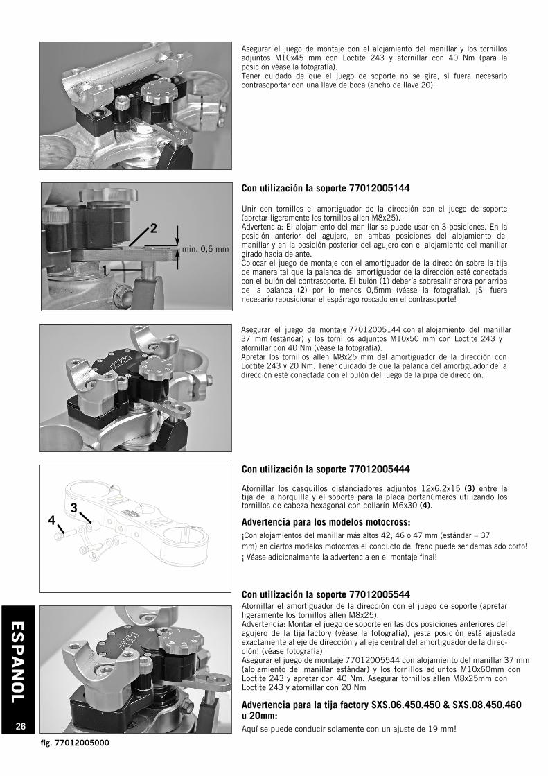
Con utilización la soporte 77012005144
Unir con tornillos el amortiguador de la dirección con el juego de soporte(apretar ligeramente los tornillos allen M8x25).Advertencia: El alojamiento del manillar se puede usar en 3 posiciones. En laposición anterior del agujero, en ambas posiciones del alojamiento delmanillar y en la posición posterior del agujero con el alojamiento del manillargirado hacia delante. Colocar el juego de montaje con el amortiguador de la dirección sobre la tijade manera tal que la palanca del amortiguador de la dirección esté conectadacon el bulón del contrasoporte. El bulón (1) debería sobresalir ahora por arribade la palanca (2) por lo menos 0,5mm (véase la fotografía). ¡Si fueranecesario reposicionar el espárrago roscado en el contrasoporte!
Con utilización la soporte 77012005544Atornillar el amortiguador de la dirección con el juego de soporte (apretarligeramente los tornillos allen M8x25).Advertencia: Montar el juego de soporte en las dos posiciones anteriores delagujero de la tija factory (véase la fotografía), ¡esta posición está ajustadaexactamente al eje de dirección y al eje central del amortiguador de la direc-ción! (véase fotografía)Asegurar el juego de montaje 77012005544 con alojamiento del manillar 37 mm (alojamiento del manillar estándar) y los tornillos adjuntos M10x60mm conLoctite 243 y apretar con 40 Nm. Asegurar tornillos allen M8x25mm conLoctite 243 y atornillar con 20 Nm
Advertencia para la tija factory SXS.06.450.450 & SXS.08.450.460u 20mm:Aquí se puede conducir solamente con un ajuste de 19 mm!
Asegurar el juego de montaje con el alojamiento del manillar y los tornillosadjuntos M10x45 mm con Loctite 243 y atornillar con 40 Nm (para laposición véase la fotografía).Tener cuidado de que el juego de soporte no se gire, si fuera necesariocontrasoportar con una llave de boca (ancho de llave 20).
2
1
Asegurar el juego de montaje 77012005144 con el alojamiento del manillar 37 mm (estándar) y los tornillos adjuntos M10x50 mm con Loctite 243 y atornillar con 40 Nm (véase la fotografía).Apretar los tornillos allen M8x25 mm del amortiguador de la dirección conLoctite 243 y 20 Nm. Tener cuidado de que la palanca del amortiguador de ladirección esté conectada con el bulón del juego de la pipa de dirección.
min. 0,5 mm
Con utilización la soporte 77012005444
Atornillar los casquillos distanciadores adjuntos 12x6,2x15 (3) entre latija de la horquilla y el soporte para la placa portanúmeros utilizando lostornillos de cabeza hexagonal con collarín M6x30 (4).
Advertencia para los modelos motocross:¡Con alojamientos del manillar más altos 42, 46 o 47 mm (estándar = 37mm) en ciertos modelos motocross el conducto del freno puede ser demasiado corto!¡ Véase adicionalmente la advertencia en el montaje final!
34
fig. 77012005000
ESPAN
OL
27
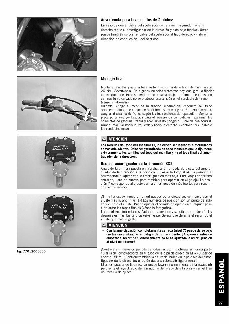
Montaje final
Montar el manillar y apretar bien los tornillos collar de la brida de manillar con20 Nm. Advertencia: En algunos modelos motocross hay que girar la fijación del conducto del freno superior un poco hacia abajo, de forma que en estado del muelle no cargado no se produzca una tensión en el conducto del freno (véase la fotografía).Cuidado: Aflojar el racor de la fijación superior del conducto del frenosolamente tanto, que el conducto del freno se pueda girar. Si fuera necesario,sangrar el sistema de frenos según las instrucciones de reparación. Montar laplaca portafaros y/o la placa para el número de competición. Examinar losconductos de gasolina, frenos y acoplamiento (longitud / libre de dobladuras).Girar el manillar hacia la izquierda y hacia la derecha y controlar si el cable olos conductos rozan.
¡Si no ha usado nunca un amortiguador de la dirección, comience con elajuste más liviano (nivel 1)! Los números de posición son un punto de indi-cación para el ajuste. Puede ajustar el tornillo de ajuste en cualquier posi-ción entre los topes finales (véase la fotografía).La amortiguación está diseñada de manera muy sensible en el área 1-4 ydespués es más fuerte progresivamente. Seleccione durante el recorrido elajuste que más le guste.
– Con la amortiguación completamente cerrada (nivel 7) puede darse bajociertas circunstancias el peligro de un accidente. ¡Asegúrese antes deempezar el recorrido si erróneamente no se ha ajustado la amortiguaciónal nivel más fuerte!
¡Controle en intervalos periódicos todas las atornilladuras; en forma parti-cular la del contrasoporte en el tubo de la pipa de dirección M6x40 (par deapriete 15Nm)! ¡Controle también la altura del bulón en la palanca del amor-tiguador de la dirección; el bulón debería sobresalir ligeramente!El amortiguador de la dirección puede lavarse normalmente de la suciedad;pero evite el rayo directo de la máquina de lavado de alta presión en el áreadel tornillo de ajuste.
Los tornillos del tope del manillar (1) no deben ser retirados o atornilladosdemasiado adentro. Debe ser garantizado en cada momento que la tija toqueprimeramente los tornillos del tope del manillar y no el tope final del amor-tiguador de la dirección.
Uso del amortiguador de la dirección SXS:Antes de la primera puesta en marcha, girar la rueda de ajuste del amorti-guador de la dirección a la posición 1 (véase la fotografía). La posición 1corresponde al ajuste con la amortiguación más baja. Para viajes en terrenoestrecho, lleno de curvas, pero también para aparcar en el garaje. La posi-ción 7 corresponde al ajuste con la amortiguación más fuerte, para recorri-dos rectos rápidos.
1
Advertencia para los modelos de 2 ciclos:En caso de que el cable del acelerador con el manillar girado hacia laderecha toque el amortiguador de la dirección y esté bajo tensión, Ustedpuede también colocar el cable del acelerador al lado derecho - visto endirección de conducción - del bastidor.
fig. 77012005000