905-519-1 02-2016 BV ausges - BAUER Gruppe · Die hydraulischen Verrohrungsmaschinen der Baureihe...
10
BV Verrohrungsanlagen Casing Oscillators BG Accessory
Transcript of 905-519-1 02-2016 BV ausges - BAUER Gruppe · Die hydraulischen Verrohrungsmaschinen der Baureihe...

BVVerrohrungsanlagenCasing Oscillators
BG
Acc
esso
ry

Die hydraulischen Verrohrungsmaschinen der Baureihe BV sinddurch ihre kompakte Bauweise zum Anbau an Drehbohrgeräteausgelegt. Die Befestigung am Unterwagen des Bohrgerätesermöglicht sowohl die Übertragung des vollen Drehmomentesauf den Rohrstrang als auch die Aktivierung des Bohrgerätege-wichtes als Reaktionsgewicht zu den Vertikalkräften beim Ein-bau der Bohrrohre. Das genaue Einrichten an der Bohrstelle wirddurch eine horizontale Relativverschiebung zwischen Verroh-rungsanlage und Bohrgerät erleichtert.Der kraftschlüssige Anbau an verschiedene Unterwagentypenwird durch den Einsatz von typisierten Adapterstücken gewähr-leistet. Die hydraulische Kraftversorgung erfolgt über die Bord-hydraulik des Bohrgerätes. Als Option kann die Verrohrungs-anlage über ein externes Hydraulikaggregat angetrieben werdenund über eine Fernbedienung unabhängig vom Bohrbetriebgesteuert werden.Die Spannschelle ist aus Segmenten zusammengesetzt. Durchdiesen Aufbau werden die Kräfte gleichmäßiger auf das Bohh-rohr übertragen.Die Verrohrungsmaschinen können durch den Einbau von Redu-zierstücken problemlos für den Einsatz mit kleineren Rohrdurch-messern auf der Baustelle umgerüstet werden.
By their sturdy and compact construction, the hydraulic casingoscillators of the BV series are designed to be used as front-endattachment to rotary drilling rigs. When mounted to theundercarriage of a rotary drilling rig, the full torque of the casingoscillator can be transferred to the casing string and the weightof the drilling rig can be activated as a reaction force to thevertical forces generated during installation of the drill casing.Exact setting-up over the pile position is achieved byadjustment of the relative horizontal position between casingoscillator and drilling rig. Mounting the casing oscillator with positive locking to differenttypes of undercarriage is achieved by type-specific adapterunits. The hydraulic power supply is provided by the on-boardhydraulic system of the drilling rig. As an alternative, the casingoscillator can also be powered by an external hydraulic powerpack and operated by remote control independently from thedrilling rig.The multi-link clamping collar ensures a positive-fit and form-specific transfer of all forces to the drill casing by uniformsurface pressure. The casing oscillator can easily be adapted onsite for use with smaller casing diameters by appropriate sets ofinserts.
2
Verrohrungsanlagen Casing oscillators
© BAUER Maschinen GmbH, 2/2016
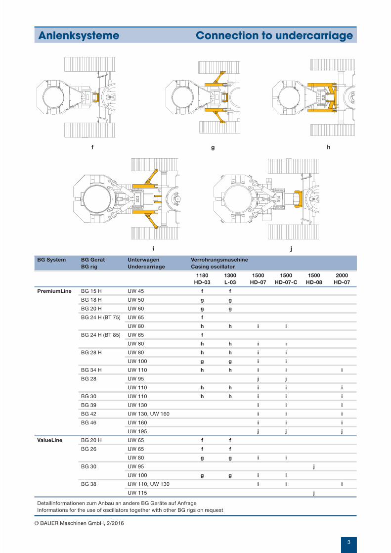
BG System BG Gerät Unterwagen VerrohrungsmaschineBG rig Undercarriage Casing oscillator
1180 1300 1500 1500 1500 2000HD-03 L-03 HD-07 HD-07-C HD-08 HD-07
PremiumLine BG 15 H UW 45 f f
BG 18 H UW 50 g g
BG 20 H UW 60 g g
BG 24 H (BT 75) UW 65 f
UW 80 h h i i
BG 24 H (BT 85) UW 65 f
UW 80 h h i i
BG 28 H UW 80 h h i i
UW 100 g g i i
BG 34 H UW 110 h h i i i
BG 28 UW 95 j j
UW 110 h h i i i
BG 30 UW 110 h h i i i
BG 39 UW 130 i i i
BG 42 UW 130, UW 160 i i i
BG 46 UW 160 i i i
UW 195 j j j
ValueLine BG 20 H UW 65 f f
BG 26 UW 65 f f
UW 80 g g i i
BG 30 UW 95 j
UW 100 g g i i
BG 38 UW 110, UW 130 i i i
UW 115 j
f g h
3
Anlenksysteme Connection to undercarriage
© BAUER Maschinen GmbH, 2/2016
i j
Detailinformationen zum Anbau an andere BG Geräte auf AnfrageInformations for the use of oscillators together with other BG rigs on request

4
BV 1180 HD-03 · BV 1300 L-03
© BAUER Maschinen GmbH, 2/2016
Technische Daten Technical data
A max. Rohrdurchmesser Max. casing diameter mm
Max. Betriebsdruck Max. operating pressure bar
Drehmoment Torque kNm
Hub Stroke mm
Hubkraft Lifting force kN
Spannkraft Clamping force kN
Drehwinkel Rotation angle °
Rohrdrehung Casing rotation mm
Gewicht (ca.) Weight (approx.) kg
Abmessungen Dimensions
B Breite Grundrahmen Width of base frame mm
C Breite Spannschelle Width of clamp mm
D Breite auf Baggerseite Width on carrier side mm
E Gesamthöhe Overall height mm
F Höhe Baggerseite Height on carrier side mm
G Höhe Spannschelle Height of clamp (mit Abdeckung) (with cover) mm
H Höhe Boden - OK Schelle Height ground to top of clamp mm
J Abstand Anlenkung - Dist. pile axis - Bohrachse carrier connection mm
horizontaler Verschiebeweg Horizontal adjustment length mm
K VK Schelle - Bohrachse Dist. pile axis - front of clamp mm
L VK Grundrahmen - Dist. pile axis Bohrachse - front of frame mm
M Gesamtlänge Overall length mm
AC B D
H
E G
KL
MJ
F
BV 1180 HD-03 BV 1300 L-03
1.180 1.300
320 320
1.075 1.140
500 500
1.450 1.450
750 750
26 25
267 283
7.500 8.000
2.010 2.270
2.030 2.300
1.300 1.300
1.480 1.480
1.038 1.038
460 460
850 850
2.275 2.335
530 530
1.000 1.100
980 1.040
3.345 3.505

Technische Daten Technical data
A max. Rohrdurchmesser Max. casing diameter mm
Max. Betriebsdruck Max operating pressure bar
Drehmoment Torque kNm
Hub Stroke mm
Hubkraft Lifting force kN
Spannkraft Clamping force kN
Drehwinkel Rotation angle °
Rohrdrehung Casing rotation mm
Gewicht (ca.) Weight (approx.) kg
Abmessungen Dimensions
B Breite Grundrahmen Width of base frame mm
C Breite Spannschelle Width of clamp mm
D Breite auf Baggerseite Width on carrier side mm
E Gesamthöhe Overall height mm
F Höhe Baggerseite Height on carrier side mm
G Höhe Spannschelle (mit Abdeckung) Height of clamp (with cover) mm
H Höhe Boden - OK Schelle Height ground to top of clamp mm
J Abstand Anlenkung - Bohrachse Dist. pile axis - carrier connection mm
horizontaler Verschiebeweg Horizontal adjustment length mm
K VK Schelle - Bohrachse Dist. pile axis - front of clamp mm
L VK Grundrahmen - Bohrachse Dist. pile axis - front of frame mm
M Gesamtlänge Overall length mm
BV 1500 HD-07
1.500
320
2.200
520
2.010
965
25
327
12.500
2.600
2.715
1.200
1.590
1.100
440
920
2.565
690
1.350
1.150
4.080
ADBC
F
MJK
E GH
L
5
BV 1500 HD-07
© BAUER Maschinen GmbH, 2/2016
6
BV 1500 HD-07-C
© BAUER Maschinen GmbH, 2/2016
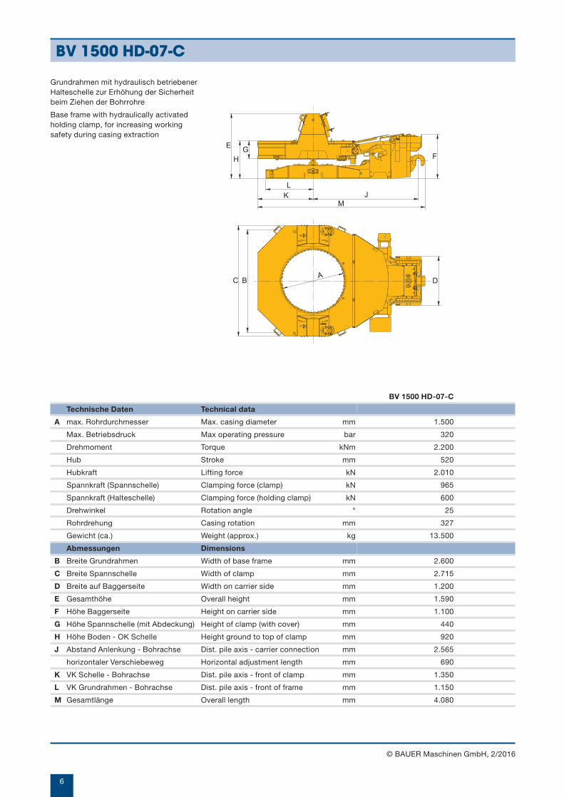
Technische Daten Technical data
A max. Rohrdurchmesser Max. casing diameter mm
Max. Betriebsdruck Max operating pressure bar
Drehmoment Torque kNm
Hub Stroke mm
Hubkraft Lifting force kN
Spannkraft (Spannschelle) Clamping force (clamp) kN
Spannkraft (Halteschelle) Clamping force (holding clamp) kN
Drehwinkel Rotation angle °
Rohrdrehung Casing rotation mm
Gewicht (ca.) Weight (approx.) kg
Abmessungen Dimensions
B Breite Grundrahmen Width of base frame mm
C Breite Spannschelle Width of clamp mm
D Breite auf Baggerseite Width on carrier side mm
E Gesamthöhe Overall height mm
F Höhe Baggerseite Height on carrier side mm
G Höhe Spannschelle (mit Abdeckung) Height of clamp (with cover) mm
H Höhe Boden - OK Schelle Height ground to top of clamp mm
J Abstand Anlenkung - Bohrachse Dist. pile axis - carrier connection mm
horizontaler Verschiebeweg Horizontal adjustment length mm
K VK Schelle - Bohrachse Dist. pile axis - front of clamp mm
L VK Grundrahmen - Bohrachse Dist. pile axis - front of frame mm
M Gesamtlänge Overall length mm
BV 1500 HD-07-C
1.500
320
2.200
520
2.010
965
600
25
327
13.500
2.600
2.715
1.200
1.590
1.100
440
920
2.565
690
1.350
1.150
4.080
A DBC
F
MJK
E GH
L
Grundrahmen mit hydraulisch betriebenerHalteschelle zur Erhöhung der Sicherheitbeim Ziehen der Bohrrohre
Base frame with hydraulically activatedholding clamp, for increasing workingsafety during casing extraction

A
E GH
MJK
L
F
DBC
7
BV 1500 HD-08
© BAUER Maschinen GmbH, 2/2016
Technische Daten Technical data
A max. Rohrdurchmesser Max. casing diameter mm
Max. Betriebsdruck Max operating pressure bar
Drehmoment Torque kNm
Hub Stroke mm
Hubkraft Lifting force kN
Spannkraft Clamping force kN
Drehwinkel Rotation angle °
Rohrdrehung Casing rotation mm
Gewicht (ca.) Weight (approx.) kg
Abmessungen Dimensions
B Breite Grundrahmen Width of base frame mm
C Breite Spannschelle Width of clamp mm
D Breite auf Baggerseite Width on carrier side mm
E Gesamthöhe Overall height mm
F Höhe Baggerseite Height on carrier side mm
G Höhe Spannschelle (mit Abdeckung) Height of clamp (with cover) mm
H Höhe Boden - OK Schelle Height ground to top of clamp mm
J Abstand Anlenkung - Bohrachse Dist. pile axis - carrier connection mm
horizontaler Verschiebeweg Horizontal adjustment length mm
K VK Schelle - Bohrachse Dist. pile axis - front of clamp mm
L VK Grundrahmen - Bohrachse Dist. pile axis - front of frame mm
M Gesamtlänge Overall length mm
BV 1500 HD-08
1.500
320
2.200
520
2.010
965
25
327
12.800
2.600
2.715
1.200
1.590
1.100
440
920
2.600
690
1.350
1.250
4.130

8
BV 2000 HD-07
Technische Daten Technical data
A max. Rohrdurchmesser Max. casing diameter mm
Max. Betriebsdruck Max. operating pressure bar
Drehmoment Torque kNm
Hub Stroke mm
Hubkraft Lifting force kN
Spannkraft (Spannschelle) Clamping force (clamp) kN
Spannkraft (Halteschelle) Clamping force (holding clamp) kN
Drehwinkel Rotation angle °
Rohrdrehung Casing rotation mm
Gewicht (ca.) Weight (approx.) kg
Abmessungen Dimensions
B Breite Grundrahmen Width of base frame mm
C Breite Spannschelle Width of clamp mm
D Breite auf Baggerseite Width on carrier side mm
E Gesamthöhe Overall height mm
F Höhe Baggerseite Height on carrier side mm
G Höhe Spannschelle (mit Abdeckung) Height of clamp (with cover) mm
H Höhe Boden - OK Schelle Height ground to top of clamp mm
J Abstand Anlenkung - Bohrachse Dist. pile axis - carrier connection mm
horizontaler Verschiebeweg Horizontal adjustment length mm
K VK Schelle - Bohrachse Dist. pile axis - front of clamp mm
L VK Grundrahmen - Bohrachse Dist. pile axis - front of frame mm
M Gesamtlänge Overall length mm
BV 2000 HD-07
2.000
320
2.965
600
2.430
1.125
920
25
436
20.000
3.150
3.200
1.200
1.960
1.175
580
1.115
2.905
690
1.400
1.590
4.655
C BA
D
LK
H
EG
M
J
F
mit unterer Halteschellewith lower holding clamp
© BAUER Maschinen GmbH, 2/2016
9
Hydaulikaggregat HD 460 Hydraulic Power Pack HD 460
© BAUER Maschinen GmbH, 2/2016
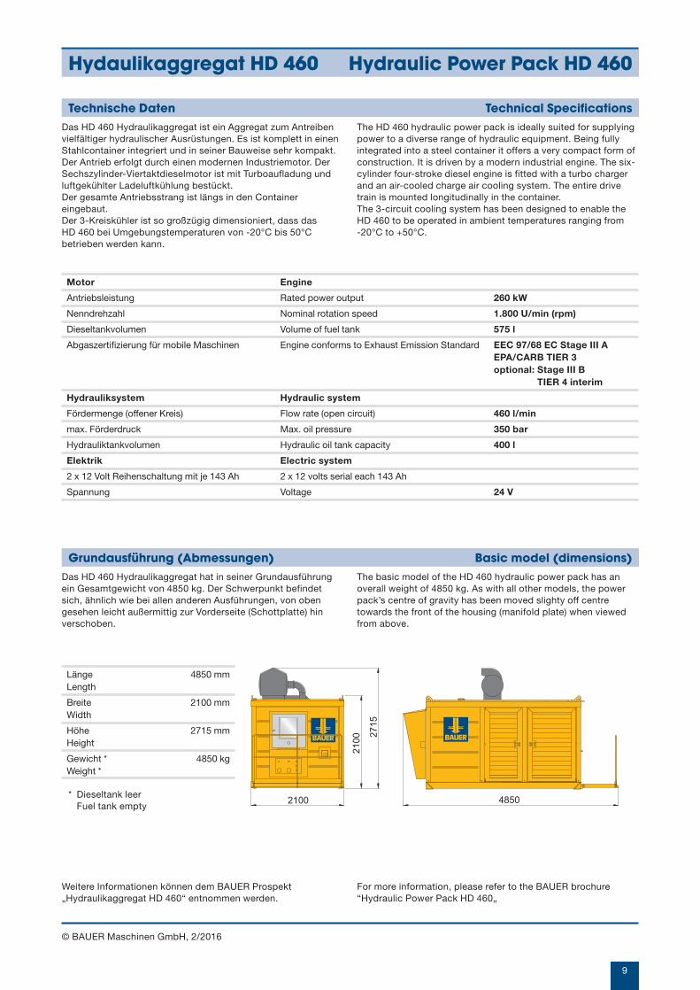
Das HD 460 Hydraulikaggregat hat in seiner Grundausführungein Gesamtgewicht von 4850 kg. Der Schwerpunkt befindetsich, ähnlich wie bei allen anderen Ausführungen, von obengesehen leicht außermittig zur Vorderseite (Schottplatte) hinverschoben.
Grundausführung (Abmessungen) Basic model (dimensions)The basic model of the HD 460 hydraulic power pack has anoverall weight of 4850 kg. As with all other models, the powerpack’s centre of gravity has been moved slighty off centretowards the front of the housing (manifold plate) when viewedfrom above.
Motor Engine
Antriebsleistung Rated power output 260 kW
Nenndrehzahl Nominal rotation speed 1.800 U/min (rpm)
Dieseltankvolumen Volume of fuel tank 575 l
Abgaszertifizierung für mobile Maschinen Engine conforms to Exhaust Emission Standard EEC 97/68 EC Stage III A EPA/CARB TIER 3 optional: Stage III B
TIER 4 interim
Hydrauliksystem Hydraulic system
Fördermenge (offener Kreis) Flow rate (open circuit) 460 l/min
max. Förderdruck Max. oil pressure 350 bar
Hydrauliktankvolumen Hydraulic oil tank capacity 400 l
Elektrik Electric system
2 x 12 Volt Reihenschaltung mit je 143 Ah 2 x 12 volts serial each 143 Ah
Spannung Voltage 24 V
Länge 4850 mmLength
Breite 2100 mmWidth
Höhe 2715 mmHeight
Gewicht * 4850 kgWeight *
* Dieseltank leerFuel tank empty
2100 4850
2100 27
15
Das HD 460 Hydraulikaggregat ist ein Aggregat zum Antreibenvielfältiger hydraulischer Ausrüstungen. Es ist komplett in einenStahlcontainer integriert und in seiner Bauweise sehr kompakt.Der Antrieb erfolgt durch einen modernen Industriemotor. DerSechszylinder-Viertaktdieselmotor ist mit Turboaufladung undluftgekühlter Ladeluftkühlung bestückt.Der gesamte Antriebsstrang ist längs in den Containereingebaut.Der 3-Kreiskühler ist so großzügig dimensioniert, dass dasHD 460 bei Umgebungstemperaturen von -20°C bis 50°Cbetrieben werden kann.
Technische Daten Technical SpecificationsThe HD 460 hydraulic power pack is ideally suited for supplyingpower to a diverse range of hydraulic equipment. Being fullyintegrated into a steel container it offers a very compact form ofconstruction. It is driven by a modern industrial engine. The six-cylinder four-stroke diesel engine is fitted with a turbo chargerand an air-cooled charge air cooling system. The entire drivetrain is mounted longitudinally in the container. The 3-circuit cooling system has been designed to enable theHD 460 to be operated in ambient temperatures ranging from -20°C to +50°C.
Weitere Informationen können dem BAUER Prospekt„Hydraulikaggregat HD 460“ entnommen werden.
For more information, please refer to the BAUER brochure “Hydraulic Power Pack HD 460„
Konstruktionsentwicklungen und Prozessverbesserungen könnenAktualisierungen und Änderungen von Spezifikation und Materialienohne vorherige Ankündigung oder Haftung erforderlich machen. Die Abbildungen enthalten möglicherweise optionale Ausstattungund zeigen nicht alle möglichen Konfigurationen. Diese Angaben und die technischen Daten haben ausschließlichInformationscharakter. Irrtum und Druckfehler vorbehalten.
Design developments and process improvements may require thespecification and materials to be updated and changed withoutprior notice or liability. Illustrations may include optional equipmentand not show all possible configurations. These and the technical data are provided as indicative informationonly, with any errors and misprints reserved.
Hydraulikaggregat Hydraulic power pack
Absturzsicherung Safety rails
Reduziereinsätze Reduction inserts
Rohrdurchmesser VerrohrungsanlageCasing diameter Casing oscillator
(mm) BV 1180 BV 1300 BV 1500 BV 2000
620 o o
750 o o
880 o o o
1.000 o o o
1.180 o o
1.200 o
1.300 o
1.500 o
1.800 o
Weitere Reduziereinsätze auf Anfrage Other reduction inserts on request
905.519.1 2/2016
BAUER Maschinen GmbHBAUER-Straße 186529 SchrobenhausenGermanyTel. +49 82 52 [email protected]
1
73
6
5
8
9
4
2
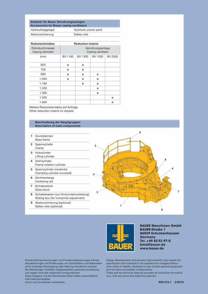
1 GrundrahmenBase frame
2 SpannschelleClamp
3 HubzylinderLifting cylinder
4 DrehzylinderClamp rotation cylinder
5 Spannzylinder (verdeckt)Clamping cylinder (covered)
6 ZentrierstangeCentering rod
7 SchiebestückSlide block
8 Schiebekasten (zur Horizontalverstellung)Sliding box (for horizontal adjustment)
9 Absturzsicherung (optional)Safety rails (optional)
Beschreibung der HauptgruppenDescription of main components
Zubehör für Bauer VerrohrungsanlagenAccessories for Bauer casing oscillators