
A method for the intelligent authoring
161
A Method for the intelligent Authoring of 3D Animations for Training and Maintenance zur Erlangung des akademischen Grades eines DOKTORS DER INGENIEURWISSENSCHAFTEN (Dr.-Ing.) der Fakultät für Maschinenbau der Universität Paderborn genehmigte DISSERTATION von Dott. Salvatore Parisi aus Trapani, Italien Tag des Kolloquiums: 06. März 2008 Referent: Prof. Dr.-Ing. Jürgen Gausemeier Koreferent: Prof. Dr. Wilhelm Schäfer
Transcript of A method for the intelligent authoring

A Method for the
intelligent Authoring of
3D Animations
for Training and Maintenance
zur Erlangung des akademischen Grades eines DOKTORS DER INGENIEURWISSENSCHAFTEN (Dr.-Ing.)
der Fakultät für Maschinenbau der Universität Paderborn
genehmigte DISSERTATION
von
Dott. Salvatore Parisi aus Trapani, Italien
Tag des Kolloquiums: 06. März 2008 Referent: Prof. Dr.-Ing. Jürgen Gausemeier Koreferent: Prof. Dr. Wilhelm Schäfer


Preface
Virtual Reality (VR) combines all technological elements for building immate-
rial three-dimensional worlds, enabling the user to perceive these worlds
through visualization, immersion, and interaction. In industry, complete digital
product representations (digital mock-ups) are used for VR-based analysis, that
even allow to simulate the functional behavior of a product for virtual prototyp-
ing purposes.
In training and maintenance, VR-based applications increasingly use 3D com-
puter animations to demonstrate and explain complex technical products. How-
ever, authoring the 3D animations is a "on-demand" process that depends on
highly customer-specific requirements. In addition, the 3D animations are cre-
ated from paper-based training and instruction manuals that provide mostly
non-formal information written in natural language.
From this, semantical problems between the 3D modeler authoring the 3D an-
imations and the customer requiring exact information arise. Reasons for such
semantical problems are domain-specific terminologies the 3D modeller does
not master, ambiguous translations from natural language into corresponding
elements of a 3D animation, and different views on a product requiring training
animations custom-tailored to end-user roles.
In this context Mr. Parisi developed a new method that facilitates the authoring
process of 3D animations for training and maintenance purposes starting from
natural language descriptions. The method solves semantical ambiguities by
using an ontology core, consisting of an existing upper ontology and one or
several domain-specific ontologies, which allow matching concepts included in
a generic training tasks. A subsequent mapping of transformations derived
from action verbs in natural language with corresponding 3D models enables
the automatic generation of the 3D animation.
Mr. Parisi proved the feasibility of his approach in a manufacturing scenario,
derived from the European project KoBaS (Knowledge Based Customized
Services for Traditional Manufacturing Sectors Provided by a Network of High
Tech SMEs), he was involved in for the past years. The work of Mr. Parisi is
an important step towards the exploitation of VR technology enabling the au-
thoring of 3D animations by non-experts.
Paderborn, May 2008 Prof. Dr.-Ing. Jürgen Gausemeier

Acknowledgments
The present work “A Method for the intelligent Authoring of 3D Animations
for Training and Maintenance” is the result of my research work at the Heinz
Nixdorf Institute, University of Paderborn. It derives mostly from the experi-
ence gained from the participation at the KoBaS and WearIT@work projects,
co-funded by the European Commission within the Sixth Framework.
I would like to thank Prof. Dr.-Ing. Jürgen Gausemeier for his trust in me and
for giving me the chance to get a PhD in a short period of time.
I am also grateful to Prof. Dr. Wilhelm Schäfer and Prof. Dr.-Ing. Jörg
Wallaschek for accepting co-advisorship, as well as to Prof. Dr.-Ing. habil. A.
Trächtler as the chairman of the board of examiners and to Prof. Dr. rer. nat. T.
Tröster as the assessor of the board of examiners.
I appreciate the assistance given by the International Graduate School at the
University of Paderborn and by the UNITY AG for the financial support.
Regarding my work a very special thanks goes to our team leader Dipl.-Ing.
Michael Grafe, always ready to give me support and suggestions, as well as to
Dr.-Ing. Rafael Radkowski, Dr.-Ing. Jan Berssenbrügge and Dipl.-Inform. Jo-
chen Bauch.
I would also like to mention all other current and former members of the Vir-
tual Reality research group “Virtuelle Umgebung” (VU) Team for having
shared a very intense time and for being an extraordinary team: Dr.-Ing. Qing
Shen, not only a colleague but also a very good friend, Dr.-Ing. Carsten Ma-
tysczok, Dr.-Ing. Peter Ebbesmeyer, Dr.-Ing. Jürgen Fründ, Dipl.-Inform. Sven
Kreft, Dipl.-Inform. Helene Wassmann, Dipl.-Ing. Sven-Kelana Christiansen,
Dipl.-Wirt.-Ing. Ute Brüseke. At the same time a thanks to our secretaries, Sa-
bine Illigen and Alexandra Dutschke, for their time and patience, to our “com-
puter doctors”, Dipl.-Ing. Karsten Mette and his apprentices, to my last
“roommate” at the HNI, M.Sc Hua Chang, and to Prof. Vita Scurto as an Eng-
lish native speaker for accepting to read and review my English.
Last but not least, a very special thanks to my wife Rita, for having supported
me and to my family for having always helped me.
Paderborn, May 2008 Salvatore Parisi


To Rita and to my family


List of published partial Results
[PBB+07a] PARISI, S.; BAUCH, J.; BERSSENBRÜGGE, J.; RADKOWSKI, R.: Ontol-ogy-driven Generation of 3D Animations for Training and Mainte-nance, Proceedings of the International Conference on Multimedia and Ubiquitous Engineering (MUE'07), pp. 608-614, 2007
[PBB+07b] PARISI, S.; BAUCH, J.; BERSSENBRÜGGE, J.; RADKOWSKI, R.: Using Ontology to create 3D Animations for Training, International Jour-nal of Software Engineering and its applications, Vol.1 No.1, July 2007, pp. 67-78

Contents Page 1
Contents
1 Introduction ................................................................................... 5
1.1 Problems................................................................................. 6
1.2 Objectives ............................................................................... 7
1.3 Approach................................................................................. 8
2 Problem Analysis: computer-based Training ............................. 9
2.1 Virtual Reality........................................................................ 11
2.2 3D Computer Animations...................................................... 15
2.2.1 3D Computer Animations for Training ....................... 18
2.2.2 Animation Authoring.................................................. 21
2.2.3 Basic Animations Techniques ................................... 24
2.3 Problems in 3D Animations Authoring .................................. 25
2.3.1 Product Complexity ................................................... 26
2.3.2 Semantic Problem..................................................... 28
2.3.3 Roles......................................................................... 30
2.3.4 Customization of the Animations............................... 32
2.4 Requirements for automating the Authoring of 3D Animations for Training Purposes............................................................ 34
2.4.1 R1 - 3D Support ........................................................ 34
2.4.2 R2 - Natural Language Understanding...................... 35
2.4.3 R3 - Knowledge-base Management.......................... 35
2.4.4 R4 - Roles Management ........................................... 36
2.4.5 R5 - Reusability of atomic Animations....................... 36
2.4.6 R6 - Support for the Training Scenario...................... 37
3 Review of 3D Authoring Approaches ........................................ 39
3.1 Scene Graph......................................................................... 39
3.2 VRML/X3D............................................................................ 41
3.3 Text-to-scene ........................................................................ 42
3.3.1 Wordseye.................................................................. 43
3.3.2 Carsim....................................................................... 44
3.3.3 Confucius .................................................................. 46
3.4 Commercial Software Solutions ............................................ 48
3.4.1 Cortona3D................................................................. 48
3.4.2 Right Hemisphere ..................................................... 50
3.4.3 Lattice3D................................................................... 51

Page 2 Contents
3.5 Call for Action and Objectives of the Research..................... 52
4 Artificial Intelligence Approaches ............................................. 55
4.1 Natural Language Processing............................................... 56
4.1.1 Logical Language Model........................................... 57
4.1.1.1 Parsing and Treebanks ............................ 59
4.1.2 Probabilistic Language Model................................... 61
4.2 Lexical Semantics................................................................. 62
4.2.1 Wordnet .................................................................... 63
4.2.2 Thematic Roles......................................................... 65
4.2.3 FrameNet.................................................................. 66
4.3 Ontology ............................................................................... 68
4.3.1 Upper Ontology......................................................... 72
4.3.1.1 Cyc........................................................... 73
4.3.1.2 SUMO ...................................................... 73
4.3.1.3 ConceptNet .............................................. 74
4.3.2 Task and Domain Ontology ...................................... 77
4.3.3 Ontology and Training............................................... 78
4.4 Ontology as Knowledge-base for the automatic Generation of 3D Computer Animations...................................................... 79
5 Ontology-driven Generation of 3D Animations ........................ 81
5.1 Basic idea ............................................................................. 81
5.2 Ontology Core....................................................................... 82
5.2.1 Upper Ontology......................................................... 84
5.2.2 Domain Ontology ...................................................... 85
5.2.2.1 Domain Ontology Development ............... 86
5.2.2.2 Part Ontology ........................................... 88
5.2.2.3 Action Ontology........................................ 91
5.2.2.4 Spatial Prepositions ................................. 93
5.2.2.5 Events ...................................................... 95
5.2.2.6 Roles........................................................ 96
5.3 Overview of the developed Method ...................................... 97
5.4 Phase 1: Training Request ................................................... 98
5.4.1 Topic of the Training Request ................................... 99
5.4.2 Content of the Training Request ............................. 101
5.5 Phase 2: Natural Language Parsing ................................... 104
5.5.1 Phrase Level ........................................................... 104
5.5.2 Word Level.............................................................. 105
5.6 Phase 3: Ontology Matching............................................... 107
5.6.1 Topic Matching........................................................ 107
Contents Page 3
5.6.2 Subtask Matching.................................................... 108
5.6.2.1 Subject ................................................... 108
5.6.2.2 Verb........................................................ 108
5.6.2.3 Object..................................................... 110
5.6.2.4 Adjectives and Adverbs.......................... 112
5.6.3 Formal Description of the Animation ....................... 113
5.7 Phase 4: Model Mapping .................................................... 114
5.8 Phase 5: Animation Script Generating ................................ 115
6 Prototype Implementation and Validation............................... 117
6.1 Ontology Choice and further Development ......................... 118
6.1.1 Upper Ontology ....................................................... 118
6.1.2 Coverage of the Training Domain ........................... 119
6.1.3 Domain Ontology .................................................... 120
6.1.3.1 Part Ontology ......................................... 121
6.1.3.2 Action Ontology...................................... 122
6.1.4 Roles....................................................................... 124
6.2 Implementation of the Process Method............................... 124
6.2.1 Training Request..................................................... 125
6.2.2 Natural Language Parser ........................................ 126
6.2.3 Ontology Matching .................................................. 127
6.2.4 Model Mapping........................................................ 130
6.2.5 Animation Script Generation ................................... 132
6.3 Evaluation ........................................................................... 133
7 Summary and Outlook .............................................................. 135
8 List of Figures............................................................................ 139
9 List of Tables ............................................................................. 143
10 Bibliography .............................................................................. 145


Introduction Page 5
1 Introduction
Computer Aided Design (CAD) has transformed an essentially paper-based
design into a digital product representation, called Digital Mock-up, which
represents the product structure of an assembly together with the geometry of
its parts. This technology allows nowadays engineers to build a virtual proto-
type, which is used to simulate together with its behavior, e.g. the dynamic
behavior, and test product characteristics without ever building a physical
model. Thus saving the related development costs and reducing time to market.
According to GAUSEMEIER (see figure 1-1), the virtual product or “virtual pro-
totyping” follows the strategic product planning, representing one of the three
cycles of the product development process; the process is concluded by the
development and planning of the related manufacturing processes, which goes
under the name of digital factory or “Digitale Fabrik” in German.
Figure 1-1: The product development process [GEK01]

Page 6 Chapter 1
Parallel to the virtual product development, CAD has also allowed the visuali-
zation of parts within a 3D model not only in a static way but through interac-
tive and dynamic 3D animations. Besides their use for a variety of purposes,
like marketing and product presentations, for entertainment within movies or
videogames, 3D computer animations are in fact used for training purposes.
Such animations (see figure 1-2) represent an easy and interactive way to de-
liver content to trainees that need to replicate in the real environment the tasks
previously visualized in the 3D animation.
Figure 1-2: Sequence from a 3D animation for the removal of fasteners in an
airplane’s landing gear brake
The advantages of such approach are represented on the one hand by the possi-
ble visualization of such animations on a normal computer monitor or through
mobile devices; this allows a training session on site, directly nearby the tech-
nical devices target of the training. On the other hand, differently from video,
which does not allow any interaction, or paper based training, which gives just
a 2D representation, the trainee can interact in 3D with the virtual product. 3D
computers animations thus allow a “learning by doing” but in an offline mode,
without interfering with the real processes.
1.1 Problems
Computer animations are usually created through a customized process, called
authoring and demanded by the customer to a professional 3D artist or mod-
eler, which is able, through the supplied 3D models and a specialized modeling
software tool, to create the required training animations.
The problem here is that the 3D artist is usually not an expert in the domain,
mechanical or electrical for example, to which the training refers. Thus, paral-
lel to the necessary 3D models, the customer must supply to the artist addi-
tional information regarding the individuation of the involved technical parts,
their movements and the effects deriving from such movements, also in rela-
tion to the connected parts.
In addition, a semantic problem arises within the definition of the training an-
imations: information between customer and 3D artist is exchanged using non
formal descriptions, like natural language or instructions manuals, which can

Introduction Page 7
present ambiguous concepts, in terms of vocabulary of elements and actions:
for example, a “resource” can refer to a “machine” or to an “employee”, ac-
cording to the context.
Furthermore, the management of different roles, each with its own need of in-
formation, has to be provided within the animation through different levels of
detail of the 3D model. In fact, according to the role target of the training, it
could be necessary to show or hidden particular parts that can be respectively
essential or not necessary, thus confusing, in order to execute the task.
The authoring of 3D computer animations is not “per se” a difficult process but
it can become a complex and time consuming task, without any possibility of
automation, under certain circumstances like high number of animations’ re-
quests, different knowledge domains, and various roles with their respective
level of detail.
1.2 Objectives
This research work aims to reduce the overall complexity of the authoring
process for 3D training animations: a method has been developed in order to
automatically generate customized animations, according to text-based descrip-
tion of the tasks that have to be executed.
To accomplish this ambitious objective, two conceptually far disciplines have
been considered and ideally joined: artificial intelligence, through an ontology
approach for the understanding of training requests’ semantic, and computer
graphics techniques, particularly focusing the computer animation domain.
The result of this “intelligent 3D authoring” is a process model that starting
from text-based descriptions, parses the training tasks by means of a natural
language parser and matches the concepts with the ones defined in an ontology.
The ontology core developed for this purpose is structured in two main parts:
an upper ontology, which contains domain independent concepts and relations,
acting like a main framework, and multiple domain ontologies that specify do-
main dependent concepts and link them to the corresponding 3D models of the
parts. Such models, which are stored in a model repository, are recalled and a
script of the animation, comprehending the necessary transformations within
the scene, is generated. The corresponding viewer is then able to use the script
to deliver the training animation to the user in an interactively way so that un-
clear tasks can be better analyzed and understood.

Page 8 Chapter 1
1.3 Approach
The book starts in Chapter 2 with a detailed description of the problem domain,
represented by the computer-based training. The need for training and the
benefits deriving are analyzed, also according to the different ways to deliver a
training session. Between the various modalities, Virtual and Augmented Real-
ity technologies are considered and described; particular attention is dedicated
to the authoring of 3D computer-animations for training purposes and the prob-
lems arising during this process. Also a series of requirements for the auto-
matic generation of 3D animations are deducted.
State-of-the-art approaches in computer graphics, focusing 3D authoring, are
introduced and analyzed in chapter 3: at first an overview of intelligent author-
ing approaches in literature, like the “text-to-scene” systems is given, followed
by actual software solutions available on the market. Since the derived re-
quirements cannot be satisfied neither by current software solutions present on
the market nor by approaches found in literature, a call for action, which in-
cludes the adoption of Artificial Intelligence techniques, has been formulated.
Chapter 4 reviews AI approaches, which are suitable to the interpretation of
text-based descriptions of training sessions in order to allow an intelligent 3D
authoring; particular attention is given to the natural language parsing and to
ontology, which constitutes the core of the proposed approach.
Chapter 5 describes as preliminary step the development of the ontology core,
whose structure is made up of an upper ontology containing domain-
independent knowledge and of multiple domain ontologies. The developed
process model is then introduced, where all single steps, building up the overall
method, are analyzed.
Chapter 6 gives describes a prototype implementation of the approach, intro-
ducing the KoBaS project that inspired this research work.
The book is then concluded by a summary and an outlook on the possible di-
rections of future work in order to refine and further develop the proposed ap-
proach.

Problem Analysis: computer-based Training Page 9
2 Problem Analysis: computer-based Training
The term “Training” represents a generic expression that deals with practice
and experience and at the same time acquisition of knowledge, somehow diffi-
cult to delimitate. It can be defined as [Rog95]:
“The act, process, or art of imparting knowledge and skill”
It is therefore reasonable considering training as a “process”; it has an input,
represented by the teaching of vocational or practical skills and notions, while
the output is represented by worker’s knowledge and experience. The acquired
experience and competencies justify then the need for training, whose effects
can be summed up essentially in the following points:
• Improving processes and products’ quality
• Reducing costs
The advantages deriving from training contributes to the effect shown through
a “learning curve”, which expresses the reduction of time required to execute a
task according to the cumulative quantity of tasks, or by the closely related
“experience curve” (see figure 2-1), which states that costs usually decline with
cumulative production and then with the experience collected.
Figure 2-1: Example of an Experience curve (logarithmic coordinates)
[Hen74-ol]
Training sessions can be delivered through many modalities, each of them be-
ing characterized by the use of various means to deliver content to the user and
by different degrees of interaction with him. Training can be roughly subdi-
vided, also according to its evolution, into two categories: traditional training
and eLearning.
To the former category belong all means that have been used traditionally be-
fore the advent of computer systems:

Page 10 Chapter 2
• Classroom training , e.g. School, University, Seminars, Workshops
• Paper-based training, e.g. Books, Instructions Manuals, Technical
Drawings
E-learning [Ros02] is a term currently used to denote a wide domain that deals
with computer-enhanced learning, which exploits also the following technolo-
gies:
• Web-based Training [Mar98]
• Simulation [Ray03]
• Serious Games [Gee03]
• Virtual and Augmented Reality [DSK+06]
Not all the modalities mentioned above have, anyway, the same efficacy as
showed in figure 2-2, by the “Cone of experience” [Dal46]; it shows on the left
in which percentage people remember, and therefore learn, according to the
way they experience a generic content, represented in the middle. On the right
the learning outcomes are displayed.
Figure 2-2: Different training modalities in the Dale’s Cone of Experience
90% of what they do
10% of what they read define describe
list explain
50% of what they hear and see
People generally remember:
70% of what they say and write
30% of what they see
20% of what they hear
Read
Hear
View images
Watch video
Attend exhibit/sites
Watch a demonstration
Participate in a hands-on workshop
Design collaborative lessons
Simulate or model a real experience
Design/perform a presentation – do the real
demonstrate
apply
practice
analyze
design
create
evaluate
People are able to (learning outcomes):

Problem Analysis: computer-based Training Page 11
The best result is therefore achieved by people, who practically execute the
task or through the simulation of a real experience, thus “learning by doing”.
This is the reason why new technologies, like Web-based Training and Virtual
and Augmented Reality, which allow a high level of involvement, are nowa-
days preferred to the old techniques, like classroom or paper-based training,
where the user acts in a passive and static way.
2.1 Virtual Reality
Virtual Reality is much more than an oxymoron1, coined in 1989 by LANIER
[Lan89], one of the pioneers in the field: in a few words, it is a computer-
generated (virtual) 3D graphical environment that, for its characteristic of im-
mersion and interaction, can be compared to an experience in a real environ-
ment (reality).
Many definitions have been given in the last decades but one of the most com-
plete, since it includes its three main characteristics, is the one of EBBESMEYER:
Virtual Reality (VR) is the sum of all technological elements for the building
and real-time preparing a computer model of material or immaterial three-
dimensional worlds, which allow the user to perceive multi-modally (Presenta-
tion) such model through its own inclusion in the model (Immersion) and as a
result to directly manipulate the model through multi-modal feedbacks (Inter-
action) [Ebb97]2.
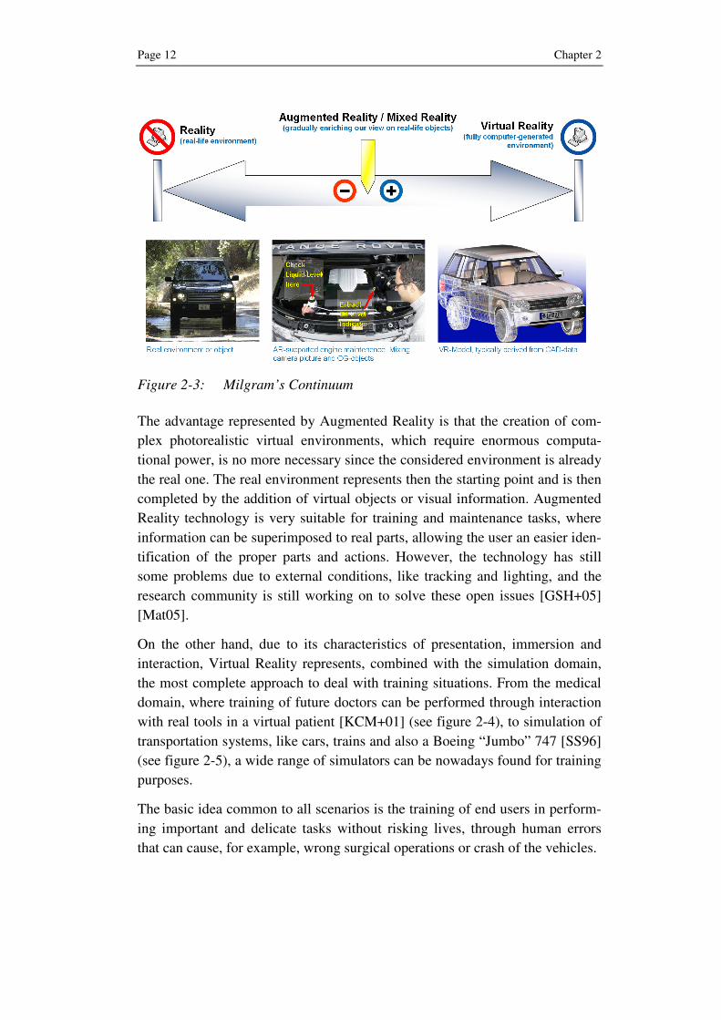
According to MILGRAM’s continuum [MTU+94] (see figure 2-3), Virtual Real-
ity, or Virtual Environment, is just one subcategory of the wider Mixed Reality
domain, given by the union of real and virtual worlds.
Between the technologies defined in the Reality-Virtuality Continuum other
forms of Mixed Reality are possible: Augmented Reality, characterized by a
real environment “augmented” with computer-generated elements, and Aug-
mented Virtuality, where the virtual environment is enriched with real parts.
Within the technologies defined in the continuum, an increasing interest has
arisen toward the Augmented Reality (AR) technology because of its powerful
approach: the user sees through its head mounted display (HMD) a real scene
captured by the camera and enriched with computer-generated information.
1 An oxymoron is a figure of speech that combines two normally contradictory terms. It is a Greek term derived from “oxy” (sharp) and “moros” (dull). Thus the word oxymoron is itself an oxymoron.
2 Translation of the author from the original definition in German
Page 12 Chapter 2
Figure 2-3: Milgram’s Continuum
The advantage represented by Augmented Reality is that the creation of com-
plex photorealistic virtual environments, which require enormous computa-
tional power, is no more necessary since the considered environment is already
the real one. The real environment represents then the starting point and is then
completed by the addition of virtual objects or visual information. Augmented
Reality technology is very suitable for training and maintenance tasks, where
information can be superimposed to real parts, allowing the user an easier iden-
tification of the proper parts and actions. However, the technology has still
some problems due to external conditions, like tracking and lighting, and the
research community is still working on to solve these open issues [GSH+05]
[Mat05].
On the other hand, due to its characteristics of presentation, immersion and
interaction, Virtual Reality represents, combined with the simulation domain,
the most complete approach to deal with training situations. From the medical
domain, where training of future doctors can be performed through interaction
with real tools in a virtual patient [KCM+01] (see figure 2-4), to simulation of
transportation systems, like cars, trains and also a Boeing “Jumbo” 747 [SS96]
(see figure 2-5), a wide range of simulators can be nowadays found for training
purposes.
The basic idea common to all scenarios is the training of end users in perform-
ing important and delicate tasks without risking lives, through human errors
that can cause, for example, wrong surgical operations or crash of the vehicles.

Problem Analysis: computer-based Training Page 13
Figure 2-4: VSOne virtual surgery [KCM+01]
Figure 2-5: NASA 747 simulator [SS96]
Another domain that exploits the same basic idea in completely different con-
ditions is represented by military applications (see figure 2-6): before fighting
Page 14 Chapter 2
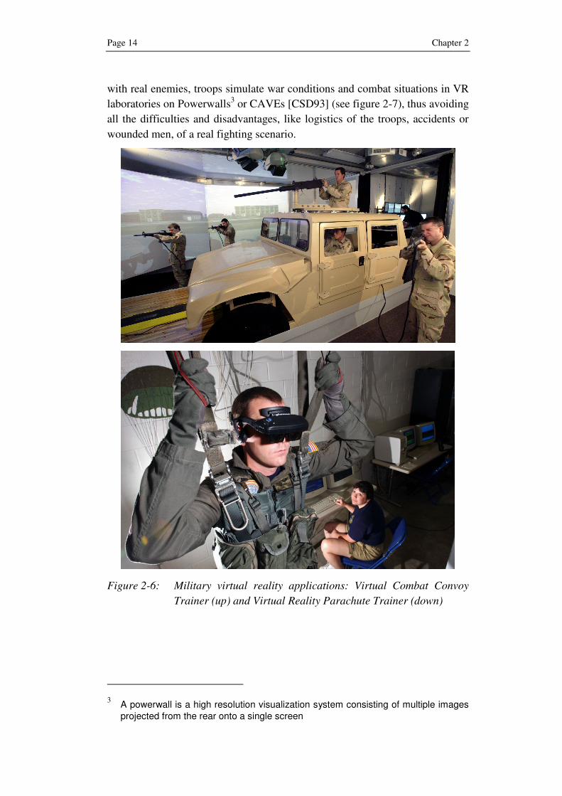
with real enemies, troops simulate war conditions and combat situations in VR
laboratories on Powerwalls3 or CAVEs [CSD93] (see figure 2-7), thus avoiding
all the difficulties and disadvantages, like logistics of the troops, accidents or
wounded men, of a real fighting scenario.
Figure 2-6: Military virtual reality applications: Virtual Combat Convoy
Trainer (up) and Virtual Reality Parachute Trainer (down)
3 A powerwall is a high resolution visualization system consisting of multiple images projected from the rear onto a single screen

Problem Analysis: computer-based Training Page 15
Figure 2-7: Virtual Reality in a CAVE4 [Bar01-ol]
An easier to manage Virtual Reality approach is represented by the so called
“desktop virtual reality” or “2½ D”, which uses common desktop computers
together with a monitor as display device. In this case the absence of the third
dimension is compensated by the illusion of 3D through projection of the ob-
jects on the monitor.
2.2 3D Computer Animations
3D computer animations represent a subclass of the wide Virtual Reality do-
main, since they do not offer the immersion feature, and sometimes interaction,
but they maintain the visualization of a 3D environment, even if displayed on a
flat 2D surface like a computer monitor or a cinema screen. It is extremely dif-
ficult describing in words what can be really appreciated in a three-dimensional
representation; anyway, such animations can be imagined as a computer-
generated film, which can be used for various purposes and with different in-
teraction levels.
4 CAVE is an immersive virtual reality environment where images are projected on three to six walls of a room-sized cube. The name is also a reference to the alle-gory of the Cave in Plato’s Republic where a philosopher contemplates perception, reality and illusion.

Page 16 Chapter 2
The sector that has been more influenced by 3D computer animations is, with-
out any doubt, the entertainment one, through the massive use of 3D in cinema
and videogames. Since the 1970s cinema has been always characterized by the
use of computer animation through special effects, like in the Star Wars Tril-
ogy, but the trend has enormously increased in the last decade. Computer an-
imations are no more used just to create special effects but also to entirely gen-
erate a film. In 1995 Toy Story (see figure 2-8), the first ever released com-
puter-animated film, impressed the public for its photorealistic quality: the
world experienced for the first time a 3D computer animation as a whole film
on the big screen.
Figure 2-8: Toy Story
Another milestone in the domain of computer-generated movies is represented
by “Final Fantasy: the Spirits within” (see figure 2-9), released in 2001, where
for the first time realistic-looking humans, instead of fantasy cartoons, have
been depicted. This opened new scenarios for the future of cinema, since theo-
retically no more real actors were needed for the realization of a movie.

Problem Analysis: computer-based Training Page 17
Figure 2-9: Final Fantasy
Together with cinema, another field, where computer animations play a fun-
damental role, is represented by the videogame industry. The evolution of
videogames has been very fast, passing from the 2D arcade-style games of the
1980s, like the cult “Pac-Man”, to actual 3D simulations of combat situations,
sport challenges or racing, like Gran Turismo (see figure 2-10) on Playstation,
as well as every-day life, like in Sims.
Figure 2-10: Gran turismo 4
New gaming consoles and hardware have allowed the use of extremely realistic
graphics, characterized by high number of details, coupled to advanced shading

Page 18 Chapter 2
techniques: videogames are nowadays so accurate and realistic that they can be
considered like “interactive films”.
A very recent application scenario of 3D computer animations is represented
by internet 3D virtual worlds, like Secondlife [Ond05] (see figure 2-11), where
each user represented by its own customizable avatar, can explore virtual is-
lands, meet new people, buy virtual land and have fun through many available
adds on.
Figure 2-11: Screenshot of a virtual campus in Second Life
2.2.1 3D Computer Animations for Training
Topic of the research approach described in this book is represented by 3D
computer animations for training purposes. Such animations are usually differ-
ent from the ones shown in the previous section: the photorealistic representa-
tion of the objects is no more the key factor because the purpose is not just en-
tertainment, but the deep understanding of technical tasks. Training animations
deal with parts of complex technical environments, like an airplane, a car or a
mechanical device; the most important factor becomes the individuation of the
involved parts and the actions that the user has to perform through them or on
them.
Before analyzing in depth training animations, the definition of the overall
training environment is necessary; a consistent and powerful approach in this

Problem Analysis: computer-based Training Page 19
sense is represented by the 5W1H (what, who, where, when, why, and how)
approach.
• What is intended for training?
• Who are the end users?
• Where does it take place?
• When does it take place?
• Why is it necessary?
• How is it performed?
Training is here meant as a process, whose result is the acquisition of knowl-
edge and skills within a productive environment, in different knowledge do-
mains and for the realization of tasks, including but not limited to, operations,
assembly and maintenance. Possible end users are therefore technical devices
operators, maintenance staff, assembly line workers as well as sales department
employees that can be trained in order to show capabilities of complex techni-
cal devices.
Two main options can be foreseen about the location of the training session: on
the one hand training can be delivered in specific laboratories, where the
trainee has the possibility to experience off-line the tasks before replicate them
in a real environment. On the other hand the trainee can be trained directly
online, during a normal shift, and can receive additional information or guid-
ance in executing the task, by more specialized and experienced employees.
Training can also be delivered through many modalities, like classical class-
room lessons, by means of paper-based documentation or by experiencing
practical tasks. In this book training is intended through the visualization of 3D
computer animations, which can be shown on a great variety of devices: beside
a traditional desktop computer and monitor, they can also be shown on a port-
able device, like a laptop computer, Tablet PC5, Smartphone
6 or PDA
7 [Par02]
(see figure 2-12).
5 A tablet PC is a notebook-like, slate-shaped mobile computer, where operation is performed by the user through touchscreen or with a stylus, digital pen, or a fingertip, instead of a keyboard or mouse.
6 A smartphone denotes any handheld device that integrates personal information management and mobile phone capabilities.
7 A Personal Digital Assistant (PDA) is a small mobile hand held device that provides computing and information storage retrieval capabilities for personal or business use, often for keeping schedule calendars and address book information.

Page 20 Chapter 2
According to a predefined training sequence, the 3D animation shows the ele-
ments of a 3D model that can be focused within the model, highlighted, moved
or hidden, in relation to the task to be performed. The virtual camera8 repre-
sents the user point of view of the virtual environment, where the action is tak-
ing place.
Figure 2-12: 3D animations on Pocket PC
To better recognize smaller details within the animation and have a better com-
prehension of the task, the following functionalities are usually provided to the
user:
• pause the animation at any time;
• rotate the virtual camera;
• zoom in and out;
• pan, i.e. scrolling the view over the design plane
If no interaction is provided, the user observes each single task contained in the
animation, in order to replicate it later on in the real environment. This is any-
8 With the term virtual camera is denoted the view of the virtual environment repre-sented within the animation, analogously to what is achieved by a real camera in the realization of a film
Problem Analysis: computer-based Training Page 21
way an unlikely scenario since most of the approaches, focusing on the indus-
trial domain, provide some degrees of interaction.
Any kind of 3D animations for industrial training tasks can be created and for
different knowledge domains: the starting point remains a 3D model of the
object, which represents the target of the training.
The use of 3D animations allows a flexible but at the same time powerful ap-
proach for training purposes, characterized by the following features:
• Training animations can be displayed also on mobile devices, thus al-
lowing an on-line training, near the target object of the training. It is
therefore the easiest way to experience a 3D training, without the need
of complex and dedicated hardware, like datagloves9 or HMDs
10, which
are not suitable for use in industrial environments.
• Unlike other training approaches, i.e. paper-based or video-based train-
ing, which allow no interaction, the trainee can dynamically experience
the training material, zooming in or rotating 3D elements if some con-
tent is not clear enough.
Once defined the main features of computer animations for training, the next
section gives an overview of the animation authoring process.
2.2.2 Animation Authoring
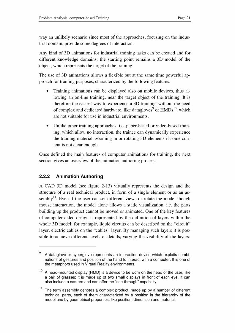
A CAD 3D model (see figure 2-13) virtually represents the design and the
structure of a real technical product, in form of a single element or as an as-
sembly11
. Even if the user can set different views or rotate the model though
mouse interaction, the model alone allows a static visualization, i.e. the parts
building up the product cannot be moved or animated. One of the key features
of computer aided design is represented by the definition of layers within the
whole 3D model: for example, liquid circuits can be described on the “circuit”
layer, electric cables on the “cables” layer. By managing such layers it is pos-
sible to achieve different levels of details, varying the visibility of the layers:
9 A dataglove or cyberglove represents an interaction device which exploits combi-nations of gestures and position of the hand to interact with a computer. It is one of the metaphors used in Virtual Reality environments.
10 A head-mounted display (HMD) is a device to be worn on the head of the user, like a pair of glasses; it is made up of two small displays in front of each eye. It can also include a camera and can offer the “see-through” capability.
11 The term assembly denotes a complex product, made up by a number of different technical parts, each of them characterized by a position in the hierarchy of the model and by geometrical properties, like position, dimension and material.
Page 22 Chapter 2
the view of the overall model can be simplified turning out some layers and
keeping visible just the really important ones for the training purposes.
Figure 2-13: CAD model of an ultra-light aircraft motor
CAD models or 3D models in general, represent the starting point of computer
animations, usually demanded to professional 3D artist artists, also known as
3D artists, who are able through specialized 3D software to create and supply
customized animations. This process, usually denoted as “animation authoring”
or “animation creation”, requires a preliminary meeting between the 3D artist
and technical staff from the customer side in order to define the “storyboard”.
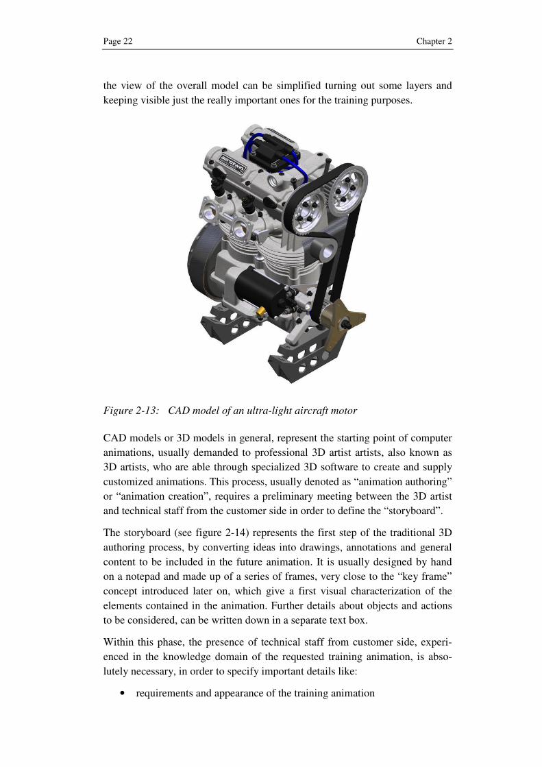
The storyboard (see figure 2-14) represents the first step of the traditional 3D
authoring process, by converting ideas into drawings, annotations and general
content to be included in the future animation. It is usually designed by hand
on a notepad and made up of a series of frames, very close to the “key frame”
concept introduced later on, which give a first visual characterization of the
elements contained in the animation. Further details about objects and actions
to be considered, can be written down in a separate text box.
Within this phase, the presence of technical staff from customer side, experi-
enced in the knowledge domain of the requested training animation, is abso-
lutely necessary, in order to specify important details like:
• requirements and appearance of the training animation
Problem Analysis: computer-based Training Page 23
• important and less important parts
• actions to be taken
Figure 2-14: Storyboard of a 3D animation [LU-ol]
In addition, the 3D artist is a computer scientist, expert in computer graphics
but not in the target training domain, where a deep technical background is
required to:
• identify parts by specific technical vocabulary
• determine the effects of a performed action
• identify eventual dependencies between technical parts or processes
• determine the content in relation to different kind of users
• establish the duration of tasks, according to the real ones
Once the storyboard has been created and the customer has supplied all the
needed information, including the necessary 3D models and eventual training

Page 24 Chapter 2
material, the 3D artist through specialized software, for example 3D Studio
Max or Maya, is able to create the requested training animation.
2.2.3 Basic Animations Techniques
Animations are created through basic techniques, which give to the user the
illusion of a real motion: this can be achieved showing to the human eye a se-
quence of still pictures, also called frames, slightly different from one other, at
a frame rate higher than 24 frames per second12
.
The most important technique for both 2D and 3D animations is the use of key
frames: they represent frames, which are selected by the 3D artist for their im-
portance, like in case of an extreme of movement in the sequence. Once the
key frames have been selected, the following task is represented by the filling
up of the time gap between them: this operation is called “in-betweening” (see
figure 2-15) and it is demanded to the computer that through an interpolation
generates the remaining still pictures to complete the sequence.
Figure 2-15: Key frames (in white) and interpolated frames (in blue)
Interpolation techniques calculate position, size, orientation and other parame-
ters of the objects in the virtual environment, so that each in-between frame
slightly differ from the adjacent frame in order to give the illusion of motion.
According to the type of equation used to average the information, different
kinds of interpolation are possible.
12 The frames per second (fps) value, used to obtain an animation, varies from 24 fps of cinema movies to more than hundreds fps in modern videogames

Problem Analysis: computer-based Training Page 25
• Linear interpolation, where the value between frames changes linearly;
• Non-linear interpolation, where the value between frames changes ac-
cording to cubic laws, like Hermite or Bezier curves
Strictly connected to interpolation techniques are the geometric transforma-
tions, which are functions, used for modifying size, location and orientation of
objects as well as of the virtual camera. The basic geometry transformations
can be grouped in:
• Translation: moving the object or the virtual camera
• Rotation: changing orientation of the object or of the virtual camera
• Scaling: changing dimensions of the object
Every transformation regards points in the virtual environment and can be rep-
resented by a matrix in homogeneous coordinates13
. The combined matrix of
the three transformations mentioned above is shown in figure 2-16, where the
included parameters represent:
• Sx, Sy and Sz: scaling factors along the three axes
• α, β and γ: rotation on the x, y and z axis
Figure 2-16: Combined transformation matrix
Another motion effect can be obtained keeping fixed the objects in the virtual
scene and moving the virtual camera’s point of view.
2.3 Problems in 3D Animations Authoring
So far a sort of “best case” has been examined, where customer and artist can
sit together and discuss about the content of a single animation. Whatever
problem arises, in the individuation of parts or definition of an action, the cus-
tomer can explain each step in detail. However, the frenetic rhythm of every-
day life and the progress in information and communication technology have
led to the widespread use of remote communication, for example through e-
13 Homogeneous coordinates are used in computer graphics to solve the problem of representing a transformation as a matrix operation
Page 26 Chapter 2
mails, telephone calls or web meetings, where the two parts are not physically
close. Therefore, the customer can directly per e-mail request a training anima-
tion and supply the 3D model together with the training tasks instructions, like
the one contained in an instruction manual. This complicates the work of the
3D artist, which has no more the possibility of clarifying in real time and
through visual indications eventual doubts about parts or actions to be dis-
played in the training animation.
In the following sections some of the main problems affecting the animation
authoring and customization are analyzed:
• Product complexity
• Semantic problem
• End user roles
• Customization of the animations
2.3.1 Product Complexity
The shift from mass production to flexible manufacturing systems in the last
decades has generated the “product differentiation” concept that for marketing
reasons let similar products differ from a very few key features or minor de-
tails; such products are more attractive for potential customers, since every
product can be adapted to customer needs through different versions or add-
ons.
However, one of the disadvantages of such approach is represented by the ex-
plosion of product complexity: instead of having a low number of standard
products, hundreds or thousands different product configurations are possible,
each differing for a very few details or parts.
Due to the difficulty to manage so many product configurations without IT
support, there has been a need since the 80s to manage product data in a more
efficient way. This has been achieved through Product Data Management
(PDM), also known as Engineering Data Management (EDM); a PDM system
adds to the management of CAD models, additional product information, like
assembly plans, manufacturing procedures and bills of material. It can be there-
fore considered like a central database where all the relevant information can
be stored, recovered and also changed by multiple users, thus allowing distrib-
uted product development processes. Over the last few years, the PDM ap-
proach has been further developed by including other aspects of the product
engineering, like production processes, product use and recycling. The result is
the management of the whole lifecycle through the Product Lifecycle Man-
agement (PLM) approach (see figure 2-17).

Problem Analysis: computer-based Training Page 27
Figure 2-17: Phases of Product Lifecycle Management [AS06]
Born as an extension of PDM, Product Lifecycle Management (PLM) approach
supports industrial manufacturing from the early design phase to the ongoing
management, product use and recycling. PLM is an integrated approach, in-
cluding a consistent set of methods, models and IT tools for managing product
information, engineering processes and applications along the different phases
of the product lifecycle [AS06]. PDM/PLM systems are useful for retrieving
3D models corresponding to different products, also searching through meta-
data but, due to their nature, they show a static view of the products.
The consequence of product complexity on the authoring of 3D training anima-
tion is the impossibility to create an animation for every product configuration,
due to the high number of possible product configurations. There is then no
margin to simplify the work of a 3D artist since a computer animation remains
a personalized creation for every single product configuration, preventing any
possibility of automation.
For example, in the manufacturing domain, modern machining centers (see
figure 2-18) are produced in more than thousands different customized con-
figurations starting from a low number of subcomponents, like base, spindle or
tool store; however, they are characterized by assembly instructions, operations
and maintenance procedures, which remain independent from the machine they
are installed onto.

Page 28 Chapter 2
Figure 2-18: Modern woodworking manufacturing machine
The difficulty to manage such a high-number of product configurations, within
the domain of 3D training animations, has led to a simplification of the prob-
lem through standardization: training animations are created for just a product
family instead of for every single product configuration. This solution implies
however some practical problems: standardized animations, omitting custom-
ized features or parts, could result in being useless for some tasks. For exam-
ple, once created a training animation for a product family, it results to be use-
less for a product of that family, which contains in a customized version a spe-
cific feature or part (e.g. an infrared sensor).
Ideally, authoring of customized animations for every product configuration is
the best solution but it results at the same time not feasible unless an automatic
creation of the animation process can be provided. This cannot be achieved just
by retrieving customized 3D models from a PDM system but introducing also a
set of actions to be coupled with the 3D model in order to create the desired
animations. Such actions must being addressed to the concepts defined within
the training tasks, which are usually expressed in a text-based form.
2.3.2 Semantic Problem
Text-based communication is nowadays still the most important way of repre-
senting and transmitting information, as evidenced by the huge amount of in-
formation exchanged through e-mails, instant messaging, internet pages, blogs
as well as newspapers and other printed materials. Information is usually ex-
changed also in working environments by means of natural language14
, which
is, by nature, non-formal: communication problems can happen very frequently
14 With the term “Natural language” is denoted a human written or spoken language used by a community, which is opposed to a formal language, e.g. a computer lan-guage.

Problem Analysis: computer-based Training Page 29
when ambiguous concepts or sentences, characterized by multiple meanings,
are misunderstood.
Context plays in this case a fundamental role for disambiguation purposes: the
same word “resource” can mean, according to the context where it is included,
raw material (also referred to as “stock”) to be worked through a machining
operation, a human resource or a device used for a specific task. To solve this
problem in industrial scenarios the Process Specification Language [SGT+00],
which has been recently published ISO standard 18629, has been developed.
Figure 2-19: Technical drawing of an airplane’s landing gear
Technical terminology in each language is characterized by its own vocabu-
lary, very difficult to manage also for a mother-tongue, who does not use such
terms in everyday life; for example, it is very difficult understanding what a
“brace strut” or a “bogie beam” is (see figure 2-19), without receiving at the
same time visual information about the parts within the structure of an airplane,
through a combination of technical drawings and textual information. Linguis-
tic elements play also a very important role in the identification of parts within

Page 30 Chapter 2
a 3D model; it is in fact possible in a PDM system to look for specific parts
through metadata within the stored 3D models.
The importance of linguistic elements goes further the individuation of techni-
cal parts: a 3D animation represents the visualization of actions, which in natu-
ral language are expressed by verbs. Sentences like “open access door” or “re-
move safety clips and tags” must be understood also from a semantic point of
view: in the examples above, what does the “open” action imply? How can be
safety clips and tags removed? Such kind of information can be found in the
semantics of the sentence, which expresses the real meaning; for example, mul-
tiple actions can correspond to the same verb followed by different target ob-
jects: “removing a screw” implies a rotation and a translation of the target ob-
ject, while in “removing the safety clips” just a translation is necessary.
Therefore a semantic problem arises when dealing with descriptions of training
sessions since they are expressed in natural language, thus in a non-formal
way. This problem involves the individuation of technical parts through spe-
cific vocabulary as well as the specification of the action verbs according to
their target objects.
2.3.3 Roles
In order to be truly efficient, training must be tailored to the real needs of the
trainee; different user types may require a different kind of information within
a training session. For example, a maintenance worker needs very detailed in-
formation of the target mechanical device (e.g. a car, an airplane or a manufac-
turing machine), including its functioning, while the end user, like a driver or a
machine operator, considers the device itself as a black-box: the focus is not on
how internal parts function rather how interacting with the device itself.
The same differences can also be found between workers in an assembly line,
which deal with a very small fraction of the overall product and therefore need
a specific view of it, or with people working in the sales department, who re-
quire an overview of the product, in order to show its features to potential cus-
tomers. Redundant or unnecessary content may create confusion in the trainee
and lead to a loss of time, thus obstructing the learning process.
The situation is analogous for 3D animations, where every user type has its
own vision of the same product: for example, a manufacturing machine can be
seen as a whole product for workers involved in the sales department, which
can show the characteristics and features of the machine through simulation of
production processes. The view delivered in the animation is then the most
general one (see figure 2-20) with a low level of detail since internal parts are
not very relevant to show the potentiality of the machine.

Problem Analysis: computer-based Training Page 31
Figure 2-20: View of a whole manufacturing machine
On the other hand, more technical end users need a more detailed view of the
same device: a machine operator can be trained, for example, on how to change
the drill bit, installed in the spindle, or on other everyday operations, which do
not require deep understanding of the machine. Training domain is in this case
represented by lower level and more specialized portions of the overall target
domain. As a consequence also animation views through the virtual camera
must be more detailed in order to appreciate the necessary details.
Very technical end users, like assembly or maintenance workers, usually re-
quire very detailed information during training sessions (see figure 2-21); sin-
gle parts are more important than the machine itself. The detail must be very
high in order to recognize the smallest parts, like screws and bolts.
Different views of the same 3D model can be obtained by the management of
layers in CAD models: layers represent virtual surfaces where virtual objects
can be placed and then be made visible or invisible, if needed, so that the final
3D model is visualized through the sum of all layers. For example, if a layer
represents the detail of lubrication pipes, once made visible, the user can im-
mediately visualize that particular subsystem within the whole model; other-
wise can be hidden, in order to simplify the overall complexity of the model.

Page 32 Chapter 2
Figure 2-21: Detail of a spindle in a manufacturing machine
There is therefore need in 3D animations for training to offer different views of
the target product by varying the visibility of the layers of the 3D model, ac-
cording to the specific end user role.
2.3.4 Customization of the Animations
A 3D animation, not only for training purposes, represents in general a unique
creation; this is also the reason why the terms “3D art” and “3D artist” have
been coined. In case of 3D animations for training purposes, the authoring
process starts from organizing in the virtual scene the 3D models representing
real elements and then the animation is created through a series of transforma-
tions of the objects as well as of the virtual camera.
The authoring process can however become extremely complex and time-
consuming in case of a high number of training animations, not only for differ-
ent product configurations but also for different end users, each of them with a
specific level of detail. The problem of a high customization of the animations,
which need to be started every time almost from scratch, cannot be automated
or simplified by using just computer animations techniques.
However, analyzing the content of a generic training session, which constitutes
also the content of the corresponding training animation, it is possible to isolate
some kind of basic actions, which can be often found in multiple training ses-
sions, like “screwing in a screw”, “removing a bolt” or “pressing a button”.
Such basic subtasks, made up of an action verb and an object, can be thought
as a “micro” or “atomic” animation. Extending such concept to a wide range of
atomic animations, every macro animation can be thought as build up recur-
Problem Analysis: computer-based Training Page 33
sively by a number of atomic animations: the advantage is represented by the
reusability, which can be achieved by managing in an intelligent way the
atomic animations instead of the macro animations.
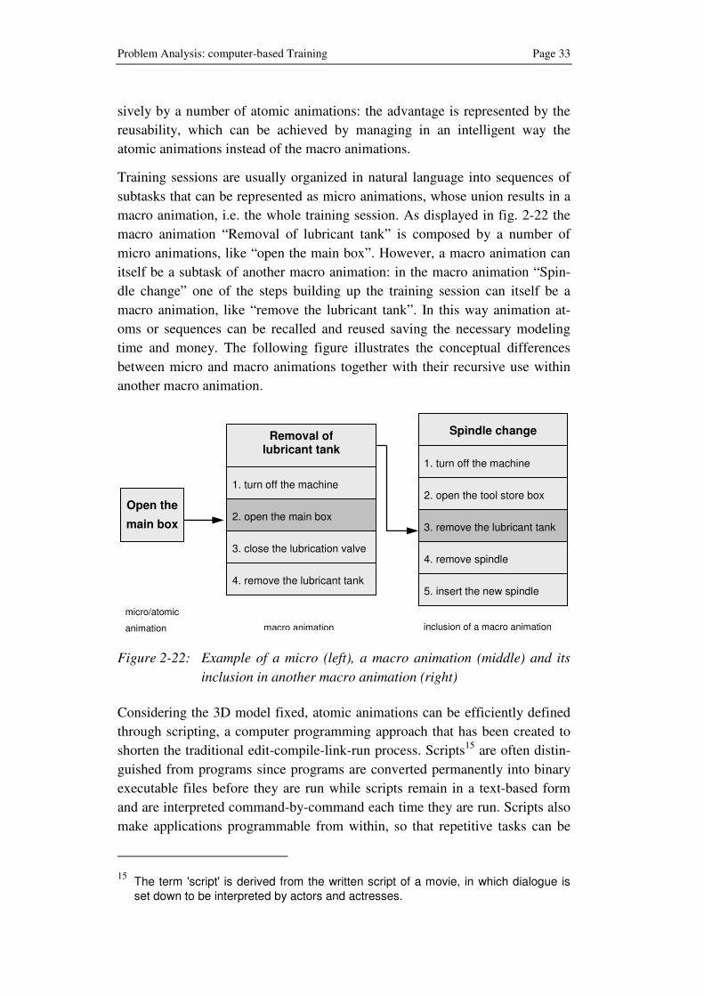
Training sessions are usually organized in natural language into sequences of
subtasks that can be represented as micro animations, whose union results in a
macro animation, i.e. the whole training session. As displayed in fig. 2-22 the
macro animation “Removal of lubricant tank” is composed by a number of
micro animations, like “open the main box”. However, a macro animation can
itself be a subtask of another macro animation: in the macro animation “Spin-
dle change” one of the steps building up the training session can itself be a
macro animation, like “remove the lubricant tank”. In this way animation at-
oms or sequences can be recalled and reused saving the necessary modeling
time and money. The following figure illustrates the conceptual differences
between micro and macro animations together with their recursive use within
another macro animation.
Figure 2-22: Example of a micro (left), a macro animation (middle) and its
inclusion in another macro animation (right)
Considering the 3D model fixed, atomic animations can be efficiently defined
through scripting, a computer programming approach that has been created to
shorten the traditional edit-compile-link-run process. Scripts15
are often distin-
guished from programs since programs are converted permanently into binary
executable files before they are run while scripts remain in a text-based form
and are interpreted command-by-command each time they are run. Scripts also
make applications programmable from within, so that repetitive tasks can be
15 The term 'script' is derived from the written script of a movie, in which dialogue is set down to be interpreted by actors and actresses.
Open the
main box
Removal of lubricant tank
1. turn off the machine
2. open the main box
3. close the lubrication valve
4. remove the lubricant tank
Spindle change
1. turn off the machine
2. open the tool store box
5. insert the new spindle
3. remove the lubricant tank
4. remove spindle
micro/atomic
animation macro animation inclusion of a macro animation
Page 34 Chapter 2
quickly automated: also 3D modeling environment like Maya or Blender offer
the possibility to the user to interact through dedicated scripting language, e.g.
MEL for Maya, or general purpose, like Python. An intelligent management of
micro and macro animations can then result in automating the creation of 3D
animations for training purposes.
2.4 Requirements for automating the Authoring of 3D An-
imations for Training Purposes
In the previous sub-sections an overview of the problems affecting the author-
ing of 3D animations for training purposes has been given. The authoring proc-
ess remains a time consuming task and animations represent customized and
unique creations, since no possibility of automation can be given to the 3D
artists.
An intelligent method, able to couple state-of-the-art artificial intelligence
techniques to computer graphics, can lead to the objective of automating the
authoring process of 3D animations. The process is delimited by a twofold kind
of constraints: on the one hand, the training information, by means of existing
instruction manuals or training material, on the other hand, the 3D content, i.e.
3D models of the objects that are the target of the training itself.
In order to reach an automation of the 3D authoring process, a set of specifica-
tions is required. As mentioned above, they cover not only the pure computer
graphics domain but also the knowledge-base management of the content of
the animations.
2.4.1 R1 - 3D Support
It can maybe seem quite obvious but the most important requirement for the
automatic 3D authoring is to support various aspects of 3D computer graphics,
like animation and interaction. No 3D modeling is required since it is assumed
that 3D models of objects involved in the animation are already defined and
available. It is anyway important to build a connection of the authoring system
with the model repository, where 3D models are stored.
The system must also be able to manage all the parameters, which build up a
3D animation, the most important of which are:
• Objects positioning
• Virtual camera positioning
• Key frames definitions
• Management of transformations
Problem Analysis: computer-based Training Page 35
Usually 3D animations can also be shown through a computer-generated video,
where no possibility of interaction is given to the end user. However, this mo-
dality does not suit very well for training purposes since it does not exploit the
interaction feature provided by 3D animations. Therefore, the content gener-
ated by the authoring system must provide to the user the necessary interaction
within the 3D animation.
2.4.2 R2 - Natural Language Understanding
The main aim of 3D animations for training is to visualize in a virtual envi-
ronment a task usually described by means of textual instructions: such de-
scription, is the starting point the 3D artist needs to understand and then to rep-
licate animating virtual objects. Training sessions have been in the past deliv-
ered essentially through paper-based content, like instruction manuals or as-
sembly drawings: in this case, the easiest way to deliver training information is
of course by means of natural language.
In order to automate the authoring system and to allow the reuse of existing
training material, natural language parsing is needed to have a first understand-
ing of the structure of the sentence and to identify and label the entities that
build up the phrase. This requirement is however complementary with the
knowledge base management since the natural language parsing alone is not
able to link linguistic elements to the corresponding concepts to be included in
the 3D animation.
In addition, the use of state-of-the-art probabilistic techniques can also allow a
preliminary identification of linguistic elements within the phrase and to avoid
ambiguities that could happen with the sole identification by means of a
knowledge-base.
2.4.3 R3 - Knowledge-base Management
In order to develop an automatic authoring process, a strong artificial intelli-
gence approach is needed; its role can be summed up in the ability to connect
entities found in natural language descriptions to concepts defined in a knowl-
edge base, to which 3D objects as well as the formal descriptions of the actions
can be associated. Knowledge-based systems allow collecting, organizing and
retrieving concepts of different domains that can be found in a generic training
session.
The knowledge base is responsible in this scenario to supply to the authoring
process the necessary information about the involved parts: if the word “drill”,
for example, is found and labeled as a noun by the natural language parsing,
task of the knowledge base is the specification of the meaning in a computer

Page 36 Chapter 2
understandable way. Also additional information like structure of the target
object and its features, as well as eventual relations to other concepts, must be
delivered to the authoring system.
The knowledge base constitutes then the bridge between knowledge of the
concepts and the 3D models that represent them in the virtual environment.
Also actions can be modeled and organized in a knowledge base so that verbs
found in a textual training session can eventually be translated in an action to
be reproduced within the a 3D animation. Furthermore, different actions can be
coupled in the three-dimensional environment to the same verb according to
different objects it refers to.
2.4.4 R4 - Roles Management
3D animations for training are usually created for a standard trainee, not taking
in account the real information needs of multiple end users, which have diverse
backgrounds, deal with specific knowledge domains and are therefore inter-
ested in different views of the same object.
An intelligent authoring system should be able to deliver 3D animations, which
can be tailored to each end user role: from a higher level overview for opera-
tions management, to more detailed views of the system for maintenance, to
extremely detailed representation of parts involved in an assembly sequence.
Level of detail can be managed essentially in two ways: on the one hand for
parts that need a high detail, the virtual camera can be positioned very close to
the object while the camera can zoom out for a more general overview of the
involved parts. On the other hand, the visibility of layers in the CAD model can
be altered in order to deliver different views of the same object to the different
roles: this is possible if specific layers are available in the CAD model for parts
of a well defined knowledge domain (lubricant circuit, electric cables or me-
chanical parts). The layers can be then set visible just for the roles needing that
particular detail; in this way, roles that need just an overview of a device are
not disturbed during the training session by details of technical parts, which are
on the other hand essential for maintenance staff or for assembly workers.
2.4.5 R5 - Reusability of atomic Animations
3D animations for training purposes are usually unique creations of a 3D artist:
once a single component within a product is modified or replaced by a new
one, the animation is no more up-to-date and results therefore to be useless.
The 3D artist must in this case build a completely new animation just starting
from the 3D model.
Problem Analysis: computer-based Training Page 37
An intelligent authoring system should be able to go beyond the usual anima-
tion authoring process, by reusing animation atoms and adding new ones in
order to generate or update 3D animations. Reusability must be achieved essen-
tially in two domains: reusability of the same 3D model for animations regard-
ing different knowledge domains or roles and reusability of the actions per-
formed, which remain independent from the 3D model.
Since for the same product different training animations could be necessary
according to the needs of various end users, reusability of existing animations
atoms could enormously simplify the animation authoring process. Atomic
animations can be authored, stored and recovered from a database if required.
One of the possibilities to achieve reusability of animation atoms is by using
animation scripts, which are formal specifications of the 3D scene, including
the world environment, involved objects and their transformations. Scripting is
also a powerful approach since no 3D modeling software is required for the
animation authoring.
2.4.6 R6 - Support for the Training Scenario
The training scenario represents a specific domain, characterized by its own
vocabulary of technical parts and verbs, which must be very detailed in order to
provide to the trainee the necessary competence.
3D computer animations for training purposes focus more on the technical ob-
jects target of the training rather than on the modelling of realistic humanoids
together with their movements or to the representation of the actions together
with realistic sounds. This is the reason why the starting point of computer an-
imations for training is the corresponding CAD model, made up of thousands
of different sub-parts, of the element to be represented in the virtual scene.
Parallel to the definition of the technical elements, also the actions to be repre-
sented in 3D animations for training purposes are just a very small part of the
every-day life: typical actions of the training domain are “removing”, “assem-
bling” or “connecting” rather than “eating”, “meeting” or “flying”.
The intelligent authoring system should therefore be able to focus on a smaller
but extremely specific knowledge domain, represented by concepts of parts and
actions typical of the training scenario.


Review of 3D Authoring Approaches Page 39
3 Review of 3D Authoring Approaches
Basic animation techniques introduced in the previous section have shown the
first steps in the animation authoring process: the initial creation by the 3D
artist of a story board and the eventual definition of the key frames as well as
the in-betweening process executed by the computer.
In this section an overview of state-of-the-art approaches, referring to the
automation of 3D animation authoring and its requirements is given. Authoring
approaches are analyzed from a higher level point of view: how to create and
deliver 3D content, starting from a non formal description. The authoring done
by a 3D artist through specialized modeling software is therefore outside the
scope of the review.
At first, the core of every 3D scene, the scene graph, is introduced as a general
purpose approach: a scene graph represents the structure of a generic virtual
scene, which includes its elements and their transformations. One possibility to
build a scene graph is also given by specific mark-up languages for 3D envi-
ronments, like VRML and X3D, which are also reviewed later on.
The most interesting approach, and at the same time closer to the aim of the
research, is represented by “text-to-scene” systems, which build a computer
graphics scene starting from a text based description.
To complete the overview of state-of-the-art technologies, some of the most
important software solutions already available on the market, are evaluated for
the automatic authoring of 3D training animations.
The section is then concluded with a review of the approaches and by the
analysis of the fulfillment of the initial requirements.
3.1 Scene Graph
Every computer generated graphics environment can be imagined as built up
by a sequence of still pictures or screenshots that, similarly to what happens in
a movie, represent a scene composed by a virtual camera, eventual lighting
sources, a group of actors or elements and by the interaction occurring between
them and the surrounding environment.
In computer graphics to every scene is associated a scene graph (see figure 3-
1); it is essentially a directed acyclic graph, where the structure consists of mul-
tiple nodes, each of which representing a geometry, property or grouping ob-
ject. Hierarchical scenes are created by adding nodes as children of grouping
nodes: in the following example the group node VW is composed by the ele-
ments “car body” and “tire”.

Page 40 Chapter 3
Figure 3-1: Example of a scene graph [GEK01]
A node may have many children but often only a single parent, with the result
that an operation applied to a group automatically propagates its effect to all of
its members. In many programs, associating a geometrical transformation ma-
trix at each group level and concatenating such matrices together is an efficient
and natural way to process such operations. A common feature, for instance, is
the ability to group related shapes or objects into a compound object that can
then be moved, transformed and selected as easily as a single object.
The two most general classifications of nodes functionality are:
• Group, which builds an hierarchy of nodes;
• Leaf, which contains descriptive data of the virtual objects in order to
render them
The building up of a scene graph represents therefore the core of the authoring
process since, once the scene graph has been built, the scene can be visualized
through the according viewer. Most of scene graph implementations for 3D
visualization, like OpenScenegraph [BO05] or Java3D just to cite the most
famous ones among them, are freely available, sometimes also with open
source, and can count on a huge developer community.

Review of 3D Authoring Approaches Page 41
3.2 VRML/X3D
Most of scene graph implementations are in the form of API16
, thus requiring
explicit programming knowledge. A different approach is represented by the
Virtual Reality Modeling Language (VRML)17
[HW96], which is a text file
format for representing 3D interactive vector graphics, designed primarily for
the World Wide Web. From the first specification VRML 1.0 a series of im-
provements have lead to version 2.0, which has been published in 1997 as ISO
standard under the name VRML97.
VRML has represented a turning point in the history of the creation of 3D vir-
tual environments through its main characteristics:
• Plain text format
• Multi-platform
• Open standard
• Hyperlinking18
• Interaction and Animation
Through a mark-up language, similar to HTML, VRML builds a hierarchical
scene graph through 36 node types, like shape nodes, properties, group nodes,
etc. VRML is also intended to be an interchange format for integrated 3D
graphics and multimedia; it can be used in a wide range of applications from
engineering and scientific visualization, to internet 3D worlds and entertain-
ment. Even if the file format is quite old and superseded by its successor X3D,
it is still used in education and in research for its open specification; it is also
supported by many CAD systems, which offer the possibility to export original
CAD models in VRML.
Extensible3D (X3D) is the successor of VRML and ISO standard for real time
3D computer graphics; it extends the features of VRML, which remains com-
patible, adding the ability to encode the scene using an XML notation as well
16 Application Programming Interface (API) represents a set of routines, protocols and tools for building software applications.
17 Originally known as Virtual Reality Markup Language was specified in its first ver-sion in 1994, deriving its structure and file format from the Open Inventor software component, originally developed by SGI.
18 Hyperlinking represents a referencing system, which allows the link of a hypertext document to another document or other resource. In the specific case, VRML can recall different objects to be included in the virtual scene just by using a normal link to that resource.
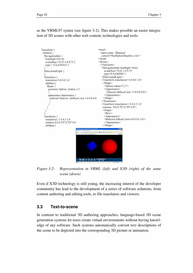
Page 42 Chapter 3
as the VRML97 syntax (see figure 3-2). This makes possible an easier integra-
tion of 3D scenes with other web content, technologies and tools.
Figure 3-2: Representation in VRML (left) and X3D (right) of the same
scene (down)
Even if X3D technology is still young, the increasing interest of the developer
community has lead to the development of a series of software solutions, from
content authoring and editing tools, to file translators and viewers.
3.3 Text-to-scene
In contrast to traditional 3D authoring approaches, language-based 3D scene
generation systems let users create virtual environments without having knowl-
edge of any software. Such systems automatically convert text descriptions of
the scene to be depicted into the corresponding 3D picture or animation.

Review of 3D Authoring Approaches Page 43
3.3.1 Wordseye
Wordseye [CS01] is probably the first approach to build a complete text-to-
scene system. It relies on a large database of 3D models and poses to depict
entities and actions. In addition every 3D model can have associated shape
displacements, spatial tags and functional properties to be used in the depiction
process.
An input text, like the one shown in the example later on, is entered; the sen-
tences are tagged and parsed. Then the output of the parser is converted to a
dependency structure: this structure is semantically interpreted and converted
into a semantic representation. Depiction rules are used to convert the semantic
representation to a set of low-level “depictors” representing 3D objects, poses,
spatial relations, color attributes and other parameters.
Core of the system is the semantic interpretation of the sentences, provided
through a parallel approach for words and for verbs. For nouns Wordseye uses
Wordnet [MBF+90], which provides various semantic relations between
words, in particular hypernym19
and hyponym20
relations. 3D objects are linked
to the WordNet database so that the model of a cat can be referenced, for ex-
ample, as a cat, a feline or a mammal. An overview of Wordnet can be found in
section 4.2.1.
Spatial prepositions define the basic layout of the scene, including relative po-
sitions, distances and orientations: they are handled by semantic functions that
analyze the elements connected by a preposition and build a representation
fragment, according to the properties of the entities.
Verbs are handled by semantic frames21
, i.e. each verb is associated to the cor-
responding semantic entry, which contains a set of verb frames; a verb frame
defines the argument structure of one sense, specifying required arguments,
like “subject”, and optional arguments, like “action location” and “action
time”.
19 A hypernym (in Greek υπερνύµιον, literally meaning 'extra name') represents a word that includes its own sub-concepts. For example, “vehicle” includes the sub-concepts “train”, “airplane” and “automobile” and is therefore a hypernym of each of those concepts.
20 A hyponym (in Greek: υπονύµιον, literally meaning 'few names') represents a word whose extension is included within that of another word. For example, “scarlet” and “vermilion” are hyponyms of “red”.
21 A semantic frame is a coherent structure of concepts related with the main one so that without knowledge of all of them, it is not possible having knowledge of the main concept.

Page 44 Chapter 3
A depiction module eventually translates the high-level semantic representation
into low-level depictors, through depiction rules. For example, the picture gen-
erated in fig 3-3 corresponds to following input text.
The donut shop is on the dirty ground. The donut of the donut
shop is silver. A green a tarmac road is to the right of the
donut shop. The road is 1000 feet long and 50 feet wide. A
yellow Volkswagen bus is eight feet to the right of the donut
shop. It is on the road. A restaurant waiter is in front of the
donut shop. A red Volkswagen beetle is eight feet in front of
the Volkswagen bus. The taxi is ten feet behind the Volks-
wagen bus. The convertible is to the left of the donut shop. It
is facing right. The shoulder of the road has a dirt texture.
The grass of the road has a dirt texture.
Figure 3-3: Example of picture generated from the text description
The system deliberately addresses the generation of static scenes rather than
the control or generation of animation. This makes the approach very interest-
ing for the automatic generations of pictures but not suitable for the research
purposes of this book.
3.3.2 Carsim
Carsim [ASS+03] [JWB+04] represents a more recent text-to-scene approach,
which differs from the previous approach since the aim is the creation of 3D

Review of 3D Authoring Approaches Page 45
animated scenes instead of pictures, of car accidents from written news reports
(see figure 3-4).
Figure 3-4: Screenshot of a CarSim animation
The system is made up of two parts, a linguistic component and a visualization
component, which communicate using a formal description of the accident.
The research approach started from a collection of development and test sets,
comprehending approximately 200 accident reports from Swedish newspapers,
characterized by different styles, lengths and amount of details, and from a
database of the Swedish traffic authority.
The language processing module reduces the text content to a formal represen-
tation. It uses information extraction techniques to map a text onto a structure
that consists of three main elements:
• A scene object, which describes the static parameters of the envi-
ronment (weather, light conditions, road configuration)
• A list of road objects, like cars and trucks, and their sequence of
movements. Also trees are included in this category.
• A list of collisions between road objects.
The resulting elements are used by the information extraction subsystem to fill
the slots of a standard template. Carsim uses a domain-specific named entity
recognition module, which detects names of persons, places, roads and car
brands [PD04]. The detected nouns are then used to identify the physical ob-
jects involved in the accident, through association with concepts defined in a
dictionary, partly derived from the Swedish Wordnet. Once defined the in-
volved entities, events like car motions and collisions, need to be detected in
Page 46 Chapter 3
order to be visualized and to animate the scene. To carry out detection a dic-
tionary of words, nouns and verbs, depicting vehicle activity and maneuvers,
has been created.
The configuration of the roads is inferred from the text information: when one
of the vehicles makes a turn, the configuration is probably a crossroads. Other
information can be contained in keywords like “crossing”, “roundabout” or
“bend”. Even if the approach is very simple, a good accuracy has been ob-
tained.
The scene generation algorithm positions the static objects and plans the vehi-
cle motion. It uses rule-based modules to check the consistency of the descrip-
tion and to estimate the start and end coordinates of the vehicles in the 3D
scene. Start and end positions of the vehicles are determined from the initial
directions as if there were no accident. Then, a second module alters the trajec-
tories, inserting the collisions described in the accident representation.
3.3.3 Confucius
Confucius [MM03] [MM04] is an intelligent multimedia storytelling interpre-
tation and presentation system: it automatically generates 3D animations with
sound and speech from natural language input. The input is thought to be rep-
resented by children’s stories, like “Alice in wonderland”, and the system is
able to represent the semantics in a way that can generate inferences about the
story, present them through animated characters and enrich them with a narra-
tor voice or incidental music matching the plot development.
The system (see figure 3-5) is composed by a script writer, a script parser,
various processors, and by a knowledge base. Aim of the script writer is to
transfer a usual English story in a drama-like script, which meets the system’s
requirements. Scripts can also be an input for the system: compared to stories,
they are easier to parse because they are partially structured, i.e. they have dis-
tinct parts for scene description, a set of characters, dialogues or monologues,
technical demands or requirements, like lights, sounds or costumes.
The script parser analyzes and subdivides the information into several func-
tional parts:
• Actor description
• Scene description
• Actions
• Dialogues
• Non-speech audio description
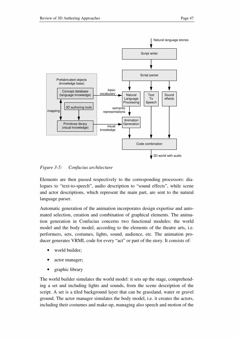
Review of 3D Authoring Approaches Page 47
Figure 3-5: Confucius architecture
Elements are then passed respectively to the corresponding processors: dia-
logues to “text-to-speech”, audio description to “sound effects”, while scene
and actor descriptions, which represent the main part, are sent to the natural
language parser.
Automatic generation of the animation incorporates design expertise and auto-
mated selection, creation and combination of graphical elements. The anima-
tion generation in Confucius concerns two functional modules: the world
model and the body model, according to the elements of the theatre arts, i.e.
performers, sets, costumes, lights, sound, audience, etc. The animation pro-
ducer generates VRML code for every “act” or part of the story. It consists of:
• world builder;
• actor manager;
• graphic library
The world builder simulates the world model: it sets up the stage, comprehend-
ing a set and including lights and sounds, from the scene description of the
script. A set is a tiled background layer that can be grassland, water or gravel
ground. The actor manager simulates the body model, i.e. it creates the actors,
including their costumes and make-up, managing also speech and motion of the
3D world with audio
Natural language stories
visual knowledge
basic vocabulary
semantic representations
Prefabricated objects
(knowledge base)
Script parser
Natural Language Processing
Text To
Speech
Script writer
Sound effects
Animation Generation
Code combination
Concept database (language knowledge)
Primitives library (visual knowledge)
mapping 3D authoring tools

Page 48 Chapter 3
synthetic characters. The graphic library contains reusable graphic components
of the knowledge base; through the library it is possible to reuse sets, properties
and performers in other stories since they are built on reusable components.
Since actor’s speech and motion may have implications on what is happening
on the virtual scene, the possibility of an interaction and of information ex-
change between the world builder and the actor manager is provided. The out-
puts coming from animation generation, text-to-speech and sound effects are
synchronized and joined together, generating a 3D world in VRML.
3.4 Commercial Software Solutions
In order to complete the overview of state-of-the-art technologies, an analysis
of the actual commercial software solutions, regarding the authoring of 3D
animations for training purposes is necessary.
As shown in the following subsections, many software solutions, which deal
with 3D training applications for the industrial domain, are already present on
the market. Just the three most powerful approaches, are reviewed separately in
the next subsections. They are software packages that are usually used beside
an existing CAD system, from which they derive the necessary 3D models in
order to create personalized training sessions and animations.
The authoring process is left to the 3D artist or to the user, which autono-
mously decides which parts must be focused, highlighted or animated. Most of
the animations are represented as an exploded view, which can be used for as-
sembly or disassembly sequences.
Even if the hierarchy of the part structure is usually visible, no support in help-
ing the individuation of allowed movements or cause/effect relations is given.
Just in one case a wizard-like approach, where predefined actions, like “re-
move” and “install”, are provided, thus simplifying the task and allowing some
automation to the authoring process.
3.4.1 Cortona3D
Cortona3D [PA-ol] is a 3D visualization solution provided by Parallelgraphics:
it feeds design data from CAD or PDM into 3D authoring tools that enable
users with no 3D expertise to create interactive simulations and associated text.
Users can then feedback data about parts or assemblies into a central repository
for analysis and troubleshooting.
Cortona3D Enterprise is a server-based solution with a 3D repository at the
core, which contains and manages part data including 3D geometry, metadata
and the knowledge base associated with parts. The tool manages also the entire

Review of 3D Authoring Approaches Page 49
process of reusing existing CAD design data to create, update and publish 3D
simulations for maintenance and operations manuals, training simulations,
parts catalogues and more.
Figure 3-6: Screenshot of the Rapid Manual Working Environment
Cortona3D Rapid Products (see figure 3-6) are modular tools enabling the re-
usability of existing CAD data or other 3D source material to author interactive
3D visualizations and simulations.
• RapidManual is a toolkit for production of digital interactive manuals
for operations, service, maintenance or repair, which use animated 3D
simulations to communicate mechanical procedures.
• RapidCatalog is a toolkit for production of digital interactive Illustrated
Parts Catalogs (IPC) through 3D exploded views to show the structure
of assemblies.
• RapidLearning is a learning toolkit for producing digital interactive
training applications using animated 3D simulations. It combines exist-
ing CAD models with training documentation to generate visually real-
istic and interactive learning.
• RapidSimulation is a toolkit for producing interactive 3D environments
that lets users experience mechanical devices and understand how com-
plex equipment really behaves. The training environment enables users
to walk through and interact within a 3D scene and change the state of
objects, simulating real-world equipment.
Cortona3D represents one of the most advanced software packages available
on the market, not only for 3D animations authoring but also for a complete 3D
technical documentation. Its “wizard-like” feature, which gives the user some

Page 50 Chapter 3
predefined action, like “install” and “remove”, is a good support and makes the
authoring process easier. The capability to understand natural language texts
remains anyway uncovered.
3.4.2 Right Hemisphere
The Right Hemisphere [RH05-ol] platform is an integrated set of products that
delivers visual product communication and collaboration. The package (see
figure 3-7) is composed by the Deep Exploration and Deep Creator tools.
Deep Exploration is a 3D multimedia authoring application, which allows to:
• Translate 2D or 3D models and multimedia files
• Search, view and mark-up 3D graphics
• Author, render and publish 3D images and animations
• CAD model translation and optimization (CAD Edition)
Figure 3-7: Training sequence using Right Hemisphere
Deep Creator is an authoring application that allows creating interactive 3D
environments, assemblies and objects. The application delivers an integrated
authoring environment which includes a 3D modeler, a texture creator, and a
scripting engine in order to produce interactive 3D content.

Review of 3D Authoring Approaches Page 51
Right Hemisphere uses an object-oriented approach, with hundreds of standard
objects, including primitives, alterations and event-driven animations, to build
3D scenes. The scripting feature completes a very comprehensive software
package, which anyway does not offer natural language support.
3.4.3 Lattice3D
XVL Studio (see figure 3-8) from Lattice3D is a family of authoring applica-
tions, which exploits the XVL22
technology [WYH+00] for 3D publishing and
communications.
Figure 3-8: Training animation with Lattice3D
• The Basic version is a full function 3D viewer with basic editing and
authoring capabilities, including measurement, annotation, and cross-
sectioning functions. It has XVL data editing functions such as material
or texture editing, IGES23
/Polygon import, and combinations of multi-
ple XVL models.
• The Standard version provides enhancement functions for 3D publish-
ing and downstream use of XVL data, including all the capabilities of
the Basic version plus animation with key frames and process defini-
tions.
22 XVL (eXtensible Virtual world description Language) is an XML-based, neutral format used for compression, conversion, and integration of 3D data.
23 The Initial Graphics Exchange Specification (IGES) defines a neutral data format that allows the digital exchange of information among Computer-aided design (CAD) systems
Page 52 Chapter 3
• The Pro version provides in addition to the features of the products
mentioned above an automated interference detection of elements, very
useful in large 3D models.
Lattice3D platform, as well as its main technology XVL, is very focused on
data compression in order to gain competitive advantages in the internet based
training or product presentation domains. On the Lattice website an “auto-
mated/semi-automated process animation” is presented as feature for the ani-
mation definition but no further explanations are given on how this process
works.
3.5 Call for Action and Objectives of the Research
The review of the state-of-the-art approaches in literature and of software solu-
tions available on the market has shown a continuously growing interest in the
area of 3D product representation and simulation, strictly connected with CAD
design.
The widespread use of 3D product data has also paved the way to its further
employ for the realization of interactive and realistic training sessions: the de-
riving 3D animations represent the best way to deliver various contents through
many modalities. Between them, the internet plays a very important role, can-
celing distances in a global world and making content accessible to a number
of users simultaneously. This explains also the increasing interest in internet
based technologies, like VRML/X3D or XVL, which exploit the net to deliver
3D content through an internet browser rather than through complex and dedi-
cated software applications to be run on specialized workstations.
From the authoring point of view, much is still left to the 3D artist, which man-
ages the realization of the animation with little software support. An object-
oriented approach with event-driven and predefined animations is already
available but nothing is given to support natural language instructions or texts;
just some scripting support is in some cases provided.
In research much importance is given to the possibility to translate natural lan-
guage into animations and the reviewed research approaches have shown its
feasibility. This requires the use of artificial intelligence techniques, like natu-
ral language processing and knowledge base management. However, up to now
no text-to-screen approach for the authoring of 3D animations for training pur-
poses has been tried in literature. Confucius represent a very sophisticated
“text-to-scene” approach, very close to satisfy the initial requirements; the tar-
get domain is however represented by the animation of humanoids in fantasy
stories, therefore far from the technical domain for training purposes.
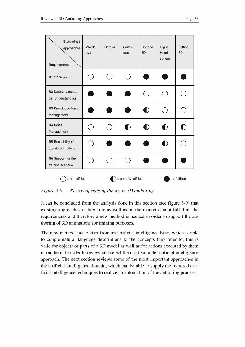
Review of 3D Authoring Approaches Page 53
Figure 3-9: Review of state-of-the-art in 3D authoring
It can be concluded from the analysis done in this section (see figure 3-9) that
existing approaches in literature as well as on the market cannot fulfill all the
requirements and therefore a new method is needed in order to support the au-
thoring of 3D animations for training purposes.
The new method has to start from an artificial intelligence base, which is able
to couple natural language descriptions to the concepts they refer to; this is
valid for objects or parts of a 3D model as well as for actions executed by them
or on them. In order to review and select the most suitable artificial intelligence
approach. The next section reviews some of the most important approaches in
the artificial intelligence domain, which can be able to supply the required arti-
ficial intelligence techniques to realize an automation of the authoring process.
State-of-art
approaches
Requirements
R2 Natural Langua-
ge Understanding
R3 Knowledge-base
Management
R4 Roles
Management
R5 Reusability of
atomic animations
R6 Support for the
training scenario
R1 3D Support
Words-
eye
Carsim Confu-
cius
Cortona
3D
Right
Hemi-
sphere
Lattice
3D
= not fulfilled = partially fulfilled = fulfilled


Artificial Intelligence Approaches Page 55
4 Artificial Intelligence Approaches
Under the term “Artificial Intelligence”, coined in 1955 by MCCARTHY, is de-
fined one of the most recent scientific domains, whose purpose as stated at the
beginning, during the Dartmouth summer conference is contained in the fol-
lowing quotation:
“Every aspect of learning or any other feature of intelligence
can in principle be so precisely described that a machine can
be made to simulate it”[MMR+55]
After the early phase of enthusiasm and great expectations, some problems
have arisen, when the domain of applications has been enlarged [RS95]:
• Most early programs contained little or no knowledge of their subject
matter; they succeeded by means of simple syntactic manipulations.
• Many of the problems that AI was attempting to solve were intractable:
the first problems were solved by trying out different combinations of
steps until the solution was found.
• Basic structures being used to generate intelligent behavior had funda-
mental limitations.
The importance of domain knowledge eventually led to the development of
knowledge-based systems and intelligent agents, which gave AI a very strong
impulse, letting it becoming a science.
Nowadays Artificial Intelligence is a wide research domain, which provides
techniques in different domains, like:
• Problem Solving
• Knowledge and reasoning
• Planning
• Uncertain knowledge and reasoning
• Learning
• Communicating, perceiving, and acting
Since not all AI domains are pertinent to the objectives of this research, just
two domains are reviewed in this section: “natural language processing”, re-
quired for a first understanding of generic and unstructured texts, and “knowl-
edge representation and retrieval”, to associate to syntactical entities concep-
tual elements, which can be depicted by 3D models and their actions. Also a
Page 56 Chapter 4
comprehensive overview of Ontology, through its different kinds, features and
advantages is given.
4.1 Natural Language Processing
Communication is the intentional exchange of information through the produc-
tion and perception of signs drawn from a shared system of conventional signs.
What sets humans apart from other animals is the complex system of structured
messages known as “language” that enables us to communicate most of what
we know about the world [RS95].
Natural Language Processing (NLP) represents the main gate to the original
Artificial Intelligence vision, where computers were imaged to be so intelligent
to interact with human intelligence through speech or text understanding and
production. Also known as “computational linguistics”, it is an interdiscipli-
nary field, whose aim is to enable computers to process human language for
text, speech or general communication tasks.
What distinguishes natural language processing applications from other generic
data processing systems is the knowledge of language. A formal language is
defined as a set of strings, which are concatenations of terminal symbols; on
the other hand, natural language, such as English, Italian or German, has no
strict definition but is used and sometimes also modified by a community of
users.
Some of the most important tasks, performed through NLP, include:
• Machine translation, i.e. automatically translation from one language to
another [Chi07]
• Web based question answering [Chk06]
• Inference, i.e. drawing conclusions based on known facts
• Information extraction
• Conversational agents, which converse with humans via natural lan-
guage [TF04]
Natural Language Systems embed syntax knowledge, like what is a word or a
verb, past participle or adjective, singular or plural. However, syntactical
analysis can give a restricted overview of a generic sentence or text since syn-
tax deals with the structure of a sentence and its representation in terms of
symbols. A problem arises when for the same word or verb, different meanings
are possible: the main point becomes the meaning of each element (lexical se-
mantics) and the combination of them (compositional semantics).
Artificial Intelligence Approaches Page 57
In order to deal with such complexity of variables and factors, Natural Lan-
guage Processing requires, together with syntax and semantics, additional
kinds of knowledge:
• Phonetics and phonology - linguistic sounds
• Morphology - meaningful components of words
• Pragmatics – relation of meanings to goals of the speaker
• Discourse – large linguistic units
In the next sections an overview of the natural language understanding, rather
than natural language generation, is given. Two different approaches are pre-
sented: on the one hand a logical approach, which starts from the definition of
mainstays, like lexicon and grammar, and includes the use of parsing trees, on
the other hand a probabilistic approach, which uses probability distribution
over a possibly infinite set of strings in order to find the most likely structure of
the sentence.
4.1.1 Logical Language Model
A logical language model is the appropriate solution when dealing with short
utterances, usually restricted to a limited domain; complete syntactical and
semantic analysis in order to extract the meaning of a generic sentence are
made possible by its relatively low complexity.
The basis of a natural language processing system is represented by a lexicon, a
list of allowable words, grouped into categories or parts of speech:
• Nouns, pronouns and names to denote things;
• Verbs, to represent actions;
• Adjectives and adverbs;
• Other elements (articles, prepositions, conjunctions, numbers, etc.)
Parallel to definition of a lexicon, a formal grammar is necessary to represent
the set of specific rules that define how a sentence needs to be structured. Since
the English Language is de facto the international language in academia, much
of the research regards English grammars.
Most grammar rule formalisms are based on the idea of a phrase structure, i.e.
a sentence is made up of different kinds of phrases. Words, which represents
“terminal symbols”, are then combined into different kinds of phrases: sen-
tence (S), noun phrase (NP), verb phrase (VP), prepositional phrase (PP) and

Page 58 Chapter 4
relative clause (RelClause). Category names such as S, NP or VP are called
“non-terminal symbols” and are used to rewrite rules or in tree structures.
A generic sentence, also indicated with S, contains at least two kinds of
phrases:
• Verb phrase (VP) - “remove the screw”, “opens the box”
• Noun phrase (NP) - “the worker”, “John”
The most commonly used mathematical system for modeling constituent struc-
ture in English as well as in other languages is the context-free grammar
(CFG), which is characterized by four parameters:
• A set of non-terminal symbols, or variables, N
• A set of terminal symbols, i.e. a lexicon, Σ, disjoint with N
• A set of rules or productions P, in the form A → α, where A is a non-
terminal and α is a string of symbols from the infinite set of strings
• A designated start symbol S
For example, the following rule states that a sentence may consist of a noun
phrase and a verb phrase; the notation followed is the Backus-Naur form
(BNF)24
.
S → NP VP
In a similar way the expression of a noun phrase (NP) can consist of either a
proper noun or a determiner (Det), followed by a nominal, where a nominal
can be constituted by one or more nouns.
NP → ProperNoun
NP → Det Nominal
Nominal → Noun | NominalNoun
A context-free grammar can be used as a device for assigning a structure to a
given sentence as well as for generating sentences. However, the latter ap-
proach is not analyzed in the next sections since it is not pertinent to the aim of
this book.
24 The Backus–Naur form is a metalanguage used to express context-free grammars, also widely used a notation, created by John Backus in 1959 [].Peter Naur later simplified Backus's notation to minimize the character set used, and as a suggestion of Donald Knuth, his name was added in recognition of his contribution.

Artificial Intelligence Approaches Page 59
4.1.1.1 Parsing and Treebanks
The parsing phase is a process that tags and labels elements of a sentence in
order to build a parse tree (see figure 4-1), whose nodes represent phrases
while leaves represent non-terminal symbols, i.e. single words, of a specific
grammar.
Parsing can be performed starting from the S symbol and then searching for a
tree that has the words as its leaves: this is called top-down parsing, opposed to
the bottom-up parsing, which starting from the words searches a tree with root
S.
Figure 4-1: Generic parse tree
In order to generate a parse tree a natural language parser is required; it is a
program that analyzes the grammatical structure of a sentence: for instance,
which groups of words are phrases or which word is respectively the subject or
the object of a verb.
Context-free grammar rules can be used, in principle, to assign a parse tree to
any sentence. It is therefore possible to build a corpus, called Treebank, where
every sentence is syntactically annotated with a parse tree. A wide variety of
tree banks, which play an important role in parsing, have been created.
The Penn Treebank project, whose notation is introduced in table 4-1, has pro-
duced treebanks from the Brown [FK79], ATIS [HGD90], Switchboard
[GHM92] and Wall Street Journal corpora of English as well as treebanks in
Arabic and Chinese. Other treebanks include the Prague Dependency Treebank
[HBH+00] for Czech, the Negra treebank [BHK+97] for German, and the Su-
sanne treebank [Sam95] for English.

Page 60 Chapter 4
Table 4-1: Penn Treebank part-of-speech tags
Tag Description Example Tag Description Example
CC Coordin.Conjunction and, but, or RB Adverb quickly
CD Cardinal number one, two RBR Adverb, comparative faster
DT Determiner a, the RBS Adverb, superlative fastest
EX Existential “there” there RP Particle up, off
FW Foreign word mea culpa SYM Symbol +, %, &
IN Preposition of, in, by TO “to” to
JJ Adjective yellow UH Interjection ah, oops
JJR Adj., comparative bigger VB Verb, base form eat
JJS Adj., superlative wildest VBD Verb, past tense ate
LS List item marker 1, 2, One VBG Verb, gerund eating
MD Modal can, should VBN Verb, past participle eaten
NN Noun, sing. or mass cat VBP Verb, non-3sg eat
NNP Proper noun, sing. IBM VBZ Verb, 3sg pres eats
NNPS Proper noun, plural Carolinas WDT Wh-determiner which, that
PDT Predeterminer all, both WP Wh-pronoun what, who
POS Possessive ending ‘s WP$ Possessive wh- whose
PRP Personal pronoun I, you WRB Wh-adverb where
PRP$ Possessive pronoun your, one’s
The sentences contained in a treebank implicitly constitute a grammar of the
language; a large number of rules can be derived from a treebank by examining
the components of any contained sentence. This high number of rules repre-
sents anyway a problem for probabilistic parsers, which are introduced in the
next section; thus a Treebank represents can be used for natural language pars-
ing but its grammar has to be modified.
Treebanks can be searched to find examples of particular grammatical phe-
nomena, either for linguistic research or for answering analytical questions
about a computational application. However, regular expressions used for text

Artificial Intelligence Approaches Page 61
search or Boolean expressions are not sufficient; specific tree-searching lan-
guages exist, like tgrep [Pit94] and tgrep2 [Roh01], which can specify con-
straints about nodes and links in a parse tree.
4.1.2 Probabilistic Language Model
Probabilistic models represent one of the biggest breakthroughs in natural lan-
guage processing in the last decades; corpora, i.e. large collections of text, like
the World Wide Web, are parsed in order to gain knowledge and to produce the
most likely analysis of new sentences, applying statistical methods.
The key need for probabilistic parsing is to solve the problem of disambigua-
tion, especially ambiguities arising with longer sentences; in fact, when proc-
essed with realistic grammars, they yield thousands or millions of possible
analyses. A probabilistic grammar offers a solution to the problem by comput-
ing the probability of each interpretation and selecting the most probable one.
The most commonly used probabilistic grammar is the probabilistic context-
free grammar (PCFG) [Boo69] [Sal69], also known as Stochastic Context-Free
Grammar (SCFG), a probabilistic augmentation of context-free grammars
where each rule is associated with a probability. A PCFG differs from a stan-
dard CFG by augmenting each rule in the set R with a conditional probability:
A → α [p]
where p is a number between 0 and 1 and expresses the probability that the
given non-terminal A is expanded to the sequence α. If we consider all the pos-
sible expansions of a non-terminal, the sum of their probabilities must be equal
to 1:
∑ =→α
α 1)(AP
PCFG probabilities can be derived by counting in a parsed corpus or by parsing
a corpus.
Each PCFG rule is treated as conditionally independent; thus the probability of
a sentence is computed by multiplying the probabilities of each rule in the
parse of the sentence. However, raw PCFGs suffer from such independence
assumption between rules. One way to deal with the problem is to split and
merge non-terminals; another solution is the use of probabilistic lexicalized
CFGs, where the basic PCFG model is augmented with a lexical head25
for
25 The lexical head of a phrase represents the most important word, e.g. the noun in a noun phrase.
Page 62 Chapter 4
each rule. The probability of a rule can then be conditioned on the lexical head
or nearby heads.
Methods for disambiguation often involve the use of corpora and Markov
models; however, this overview goes not too deep, leaving to the reader more
specialized publications on the topic. One of the most important parser avail-
able is the Stanford Lexical Parser [KM02] [KM03].
4.2 Lexical Semantics
So far an overview of the structure of an utterance has been analyzed but noth-
ing about the meaning has been specified: this task is the aim of lexical seman-
tics26
, which represents the study of the meaning in systems of signs and the
systematic meaning-related connections between words.
Before starting the analysis some basic definitions regarding the “word” con-
cept are required [JM00]; the term lexeme is usually used to mean the pairing
of the orthographic and phonological form with its meaning, while a lexicon is
a finite list of lexemes. A lemma or citation form is the grammatical form
used to represent a lexeme, usually the base form. Thus “miracle” is the lemma
for “miracles” and “give” the one for “give, gave, given”; specific forms, like
“gave” or “given” are called wordforms while the mapping from a wordform to
a lemma is called lemmatization.
It is quite common that a lemma, for example “paper”, has more than a sense:
it can refer to the material or to a scientific article; a sense or word sense is a
discrete representation of one aspect of the meaning of a word. The senses of a
word might not have any particular relation between them but just sharing the
orthographic form. In such cases, the senses are homonyms and their relation is
homonymy. On the other hand, when senses are related semantically, such
relation is called polisemy.
Metonymy is the use of one aspect of a concept or of an entity to refer to the
entity itself or to some of its specific aspects. Metonymy is used, for example,
in the phrase “the White House” to refer to the administration of the office
rather than to the building itself.
For computational purposes, a sense is can be specified through definitions,
similar to the ones used in a dictionary, via its relations with other senses.
Given a large database of sense relations, an application is capable of perform-
ing sophisticated semantic tasks.
26 The term derives from Greek sēmantikos, giving signs, significant, symptomatic, derived from sēma (σῆµα), sign.

Artificial Intelligence Approaches Page 63
Another approach is to create a small set of finite set of semantic primitives,
atomic units of meaning, and then create each sense definition out of these
primitives. This approach is quite common when defining aspects of the mean-
ing of events such as semantic roles.
Some of the relations between senses that have received significant computa-
tional investigation include:
• Synonymy and Antonymy: when the meanings of two different lem-
mas are identical or nearly identical, the two senses are synonyms, i.e.
they are substitutable one for the other in any sentence. Antonyms, by
contrast are lemmas with opposite meanings.
• Hyponymy: one sense is a hyponym of another sense if the first one is
more specific, e.g. a car is a hyponym of vehicle. Conversely a vehicle
is defined as a hypernym of car.
• Meronymy: it represents the part-whole relation, e.g. wheel is a mero-
nym of car.
While the relations defined so far are binary, a semantic field [RMN+00] is an
attempt to capture a more structured relation among entire sets of lemmas from
a single domain. The following set of lemmas can be characterized by a set of
binary relations, even if the result is not a complete account of how these
words are related:
reservation, flight, travel, buy, price, cost, fare, rates, meal, plane
They are all related to common sense background information concerning air
travel. Background knowledge of this kind has been studied under a variety of
frameworks and is known as frame [Fil85], model [Joh83], or script [SA73].
4.2.1 Wordnet
The most commonly used resource for English sense relations is the WordNet
lexical database [MBF+90]. Wordnet consists of three separate databases, one
each for nouns and verbs, and a third one for adjectives and adverbs. Each da-
tabase contains a set of lemmas, each one annotated with a set of senses. The
current 3.0 release has more than 100.000 nouns, 10.000 verbs, 20.000 adjec-
tives and almost 5.000 adverbs; it can be accessed also online or locally on
every pc, once downloaded the free software package.

Page 64 Chapter 4
Figure 4-2: Extract from WordNet online results for the lemma “open
In addition various lexical sense relations (see table 4-2) are implemented: each
synset is related to its immediately more general and more specific synsets via
direct hypernym and hyponym relations.
These relations can be followed to produce longer chains of more general or
more specific synsets. Each sense, like the ones displayed in figure 4-2, is
composed by a gloss, i.e. a dictionary-style definition, a list of synonyms,
called synset27
, for the sense and sometimes also usage examples.
Even if WordNet is a lexical reference system, it is also usually referred to as
an Ontology; however, this assumption is not fully correct since the relations
defined are just of the kind hyponymy/hyperonymy.
27 Synset stays for “synonymy set” and can be thought as a way to represent a con-cept. Thus instead of representing concepts using logical terms, WordNet repre-sent them as a lists of word senses.
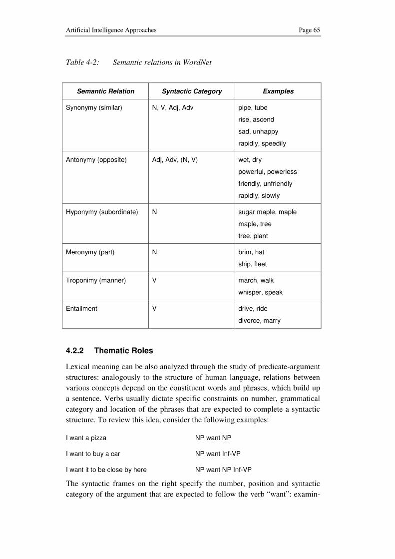
Artificial Intelligence Approaches Page 65
Table 4-2: Semantic relations in WordNet
Semantic Relation Syntactic Category Examples
Synonymy (similar) N, V, Adj, Adv pipe, tube
rise, ascend
sad, unhappy
rapidly, speedily
Antonymy (opposite) Adj, Adv, (N, V) wet, dry
powerful, powerless
friendly, unfriendly
rapidly, slowly
Hyponymy (subordinate) N sugar maple, maple
maple, tree
tree, plant
Meronymy (part) N brim, hat
ship, fleet
Troponimy (manner) V march, walk
whisper, speak
Entailment V drive, ride
divorce, marry
4.2.2 Thematic Roles
Lexical meaning can be also analyzed through the study of predicate-argument
structures: analogously to the structure of human language, relations between
various concepts depend on the constituent words and phrases, which build up
a sentence. Verbs usually dictate specific constraints on number, grammatical
category and location of the phrases that are expected to complete a syntactic
structure. To review this idea, consider the following examples:
I want a pizza NP want NP
I want to buy a car NP want Inf-VP
I want it to be close by here NP want NP Inf-VP
The syntactic frames on the right specify the number, position and syntactic
category of the argument that are expected to follow the verb “want”: examin-

Page 66 Chapter 4
ing different possibilities in the use of a verb, it is possible to collect important
information about the expected participants in the events defined by each verb.
Thematic roles express the meaning that a lexical element, e.g. a noun phrase,
plays with respect to the action or state described by the main verb. This is
achieved through thematic relations, whose main components can be summed
in the table 4-3. Thematic roles are used to perform semantic restrictions on the
elements that a specific verb can support.
Table 4-3: Thematic roles
Agent performs the action
Experiencer receives sensory or emotional input
Theme undergoes the action but does not change its state
Patient undergoes the action and has its state changed
Instrument Used to carry out the action
Natural Cause
mindlessly performs the action
Location Place where the action occurs
Goal aim of the action is directed towards
Recipient a kind of goal associated with verbs expressing a change in ownership
Source where the action originated
Time the time at which the action occurs
Beneficiary the entity for whose benefit the action occurs
4.2.3 FrameNet
The FrameNet project [BFL98] is a semantic role labeling project, where roles
are specific to a frame, which represents a script-like structure that instantiates
a set of frame-specific semantic roles called frame elements. Each word evokes
a frame and profiles some aspect of the frame and its elements; for example,
the “removing” frame is defined as follows:
An Agent causes a Theme to move away from a location, the
Source. The Source is profiled by the words in this frame, just
as the Goal is profiled in the Placing frame.
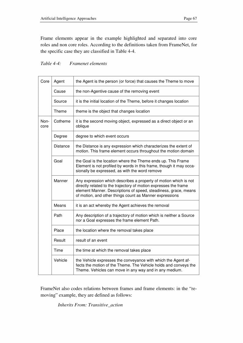
Artificial Intelligence Approaches Page 67
Frame elements appear in the example highlighted and separated into core
roles and non core roles. According to the definitions taken from FrameNet, for
the specific case they are classified in Table 4-4.
Table 4-4: Framenet elements
Agent the Agent is the person (or force) that causes the Theme to move
Cause the non-Agentive cause of the removing event
Source it is the initial location of the Theme, before it changes location
Core
Theme theme is the object that changes location
Cotheme it is the second moving object, expressed as a direct object or an oblique
Degree degree to which event occurs
Distance the Distance is any expression which characterizes the extent of motion. This frame element occurs throughout the motion domain
Goal the Goal is the location where the Theme ends up. This Frame Element is not profiled by words in this frame, though it may occa-sionally be expressed, as with the word remove
Manner Any expression which describes a property of motion which is not directly related to the trajectory of motion expresses the frame element Manner. Descriptions of speed, steadiness, grace, means of motion, and other things count as Manner expressions
Means it is an act whereby the Agent achieves the removal
Path Any description of a trajectory of motion which is neither a Source nor a Goal expresses the frame element Path.
Place the location where the removal takes place
Result result of an event
Time the time at which the removal takes place
Non-core
Vehicle the Vehicle expresses the conveyance with which the Agent af-fects the motion of the Theme. The Vehicle holds and conveys the Theme. Vehicles can move in any way and in any medium.
FrameNet also codes relations between frames and frame elements: in the “re-
moving” example, they are defined as follows:
Inherits From: Transitive_action

Page 68 Chapter 4
Subframe of: Cause_motion
Precedes: Placing
Uses: Motion
Is Used By: Emptying, Undressing
See Also: Placing
The major product of this work, the FrameNet lexical database, currently con-
tains more than 10,000 lexical units, 6,100 of which are fully annotated, in ap-
proximately 825 semantic frames and exemplified in more than 135,000 anno-
tated sentences.
4.3 Ontology
Even though ontology research has begun in the early 90s in the knowledge
base community, the research activity has been recently spread over the web
technology community by the semantic web28
movement [BHL01]. Nowadays
ontology is a very popular topic, even if still there seems to be some misunder-
standing on what an ontology really is. One of the key concepts to understand
ontology is “conceptualization”, which includes “the objects presumed or hy-
pothesized to exist in the world and their relations”. [GN87]
An example can help to better understand what in practice a conceptualization
is: the task of the blocks world (see figure 4-3) consists in stacking blocks in
the goal configuration, using a robot hand.
The target world can be exhaustively represented by the concepts “entity” and
“relation”: the former represents the physical objects of the target world, like
block, robot hand and table, while the latter specifies the relations between the
objects. The modeling of the target world is left to the experience of the
knowledge engineer and therefore to its point of view: there is in fact not just a
unique solution but multiple choices, each of them being correct. One way to
model the target world is represented by the Conceptualization 1 in table 4-5,
which defines three blocks (block A, block B and block C), a robot hand and a
table as objects, together with four relations:
28 In 1999 Tim Berners-Lee, inventor of the World Wide Web, stated: “I have a dream for the Web [in which computers] become capable of analyzing all the data on the Web – the content, links, and transactions between people and computers. A ‘Se-mantic Web’, which should make this possible, has yet to emerge, but when it does, the day-to-day mechanisms of trade, bureaucracy and our daily lives will be handled by machines talking to machines.”
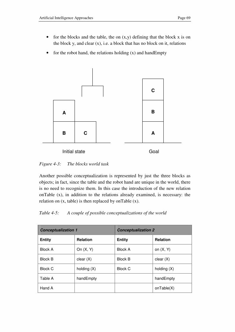
Artificial Intelligence Approaches Page 69
• for the blocks and the table, the on (x,y) defining that the block x is on
the block y, and clear (x), i.e. a block that has no block on it, relations
• for the robot hand, the relations holding (x) and handEmpty
Figure 4-3: The blocks world task
Another possible conceptualization is represented by just the three blocks as
objects; in fact, since the table and the robot hand are unique in the world, there
is no need to recognize them. In this case the introduction of the new relation
onTable (x), in addition to the relations already examined, is necessary: the
relation on (x, table) is then replaced by onTable (x).
Table 4-5: A couple of possible conceptualizations of the world
Conceptualization 1 Conceptualization 2
Entity Relation Entity Relation
Block A On (X, Y) Block A on (X, Y)
Block B clear (X) Block B clear (X)
Block C holding (X) Block C holding (X)
Table A handEmpty handEmpty
Hand A onTable(X)
B
A
C
A
C
B
Goal Initial state
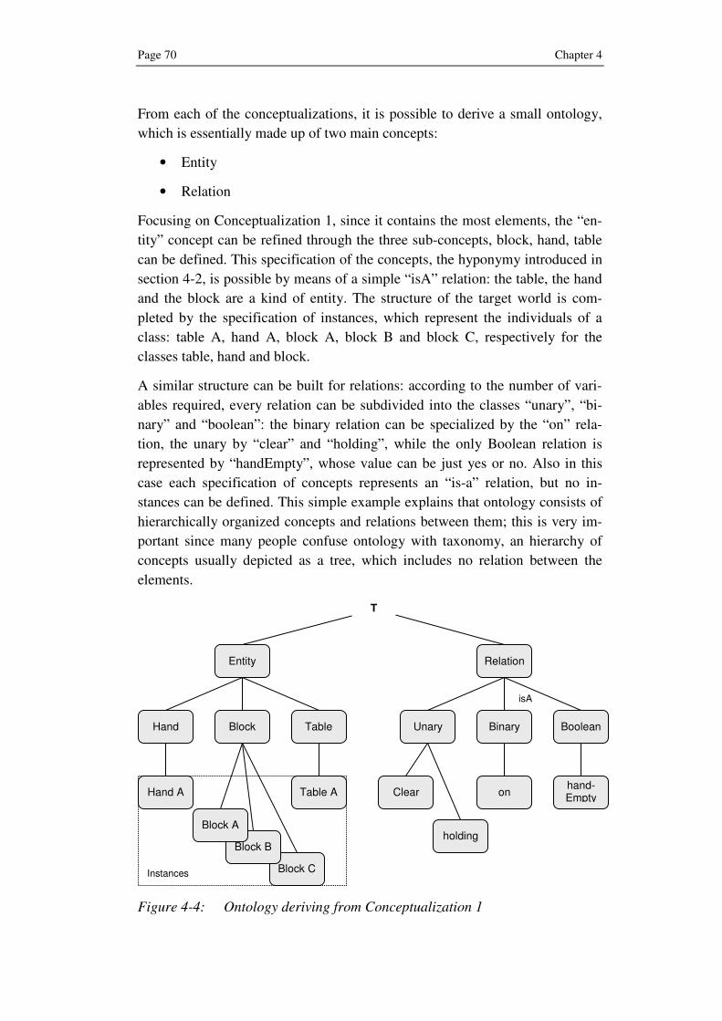
Page 70 Chapter 4
From each of the conceptualizations, it is possible to derive a small ontology,
which is essentially made up of two main concepts:
• Entity
• Relation
Focusing on Conceptualization 1, since it contains the most elements, the “en-
tity” concept can be refined through the three sub-concepts, block, hand, table
can be defined. This specification of the concepts, the hyponymy introduced in
section 4-2, is possible by means of a simple “isA” relation: the table, the hand
and the block are a kind of entity. The structure of the target world is com-
pleted by the specification of instances, which represent the individuals of a
class: table A, hand A, block A, block B and block C, respectively for the
classes table, hand and block.
A similar structure can be built for relations: according to the number of vari-
ables required, every relation can be subdivided into the classes “unary”, “bi-
nary” and “boolean”: the binary relation can be specialized by the “on” rela-
tion, the unary by “clear” and “holding”, while the only Boolean relation is
represented by “handEmpty”, whose value can be just yes or no. Also in this
case each specification of concepts represents an “is-a” relation, but no in-
stances can be defined. This simple example explains that ontology consists of
hierarchically organized concepts and relations between them; this is very im-
portant since many people confuse ontology with taxonomy, an hierarchy of
concepts usually depicted as a tree, which includes no relation between the
elements.
Figure 4-4: Ontology deriving from Conceptualization 1
Instances
isA
Table
hand-Empty
Entity
Block Hand Unary Binary Boolean
Relation
on Clear
holding
Table A Hand A
Block C
Block B
Block A
T

Artificial Intelligence Approaches Page 71
The term Ontology derives from philosophy, where it means theory of exis-
tence: it tries to explain the being and the world by introducing a system of
critical categories to account things and their intrinsic relations. From an AI
point of view, a widely accepted definition is the one of GRUBER [Gru93]:
“Ontology is an explicit formal specification of a conceptu-
alization”
where the single elements can be characterized as follows:
• explicit, because domain and constraints must be explicitly defined
• formal, i.e. machine readable
• conceptualization, intended as an abstract, simplified world
BORST [Bor97], underlying the knowledge sharing nature of ontology, slightly
modified it in:
“Ontology is a formal specification of a shared conceptuali-
zation”
From knowledge-based systems point of view, it is defined as “a theory/system
of concepts/vocabulary used as building blocks of an information processing
system” by MIZOGUCHI.
As introduced by the example mentioned before an Ontology is essential built
up by three mainstays: classes, instances and relations. A class is a group, set
or collection of elements, called instances or individuals, which share the same
characteristics. The relations connecting classes build the structure of the on-
tology can be subdivided into:
• Hyperonymy/Hyponymy (or Subsumption), defines subclasses and su-
perclasses relations, e.g. “is-a” relation;
• Meronymy/Holonymy, denotes a relation between the whole and its
subparts, e.g. “part-of” relation;
• Synonymy/Antonymy, defines concepts whose meaning is equal or dis-
joint.
• Cardinality, how many parameters are necessary for a class or attribute
Ontology engineering represents the evolution of knowledge engineering,
which consisted mainly in the exploitation of the rule base technology and its
if-then rules, within knowledge based systems. This shift has been caused
mainly by difficulties in the maintenance of rule base systems and in knowl-
edge sharing and reusing in knowledge bases, so that such systems had to be
built from scratch.

Page 72 Chapter 4
Ontology engineering is a research methodology, which allows the design ra-
tionale of a knowledge base, kernel conceptualization of the world of interest,
semantic constraints of concepts together with sophisticated theories and tech-
nologies enabling accumulation of knowledge [Miz03].
Different kinds of ontology have been developed so far [UG96] [UJ99], from
very generic and domain independent to specific ontologies, dealing with a
specific task or domain. An overview of the most important approaches is
given in the following sections.
4.3.1 Upper Ontology
Ontology represents by its nature a wide domain, which has been seen from
different point of views by the research community: on the one hand, research-
ers stated that ontology should be very generic, widely applicable and share-
able; on the other hand some thought ontology to be domain-specific, like a
knowledge base. Both definitions are correct, they just point to different types
of ontologies, which are analyzed in detail in the following sections.
An Upper Ontology is an attempt to build a higher level ontology that de-
scribes very general concepts, common to all domains. It tries to formally de-
fine the higher level categories, which explain what exists in the world: the
topic has been investigated for years by philosophers, like Aristotle’s ten cate-
gories such as substance, quantity, quality, relation, place, time, position, state,
action and affection.
Some of the most important contributions in the upper ontology domain are
due to Sowa and Guarino: SOWA’s [Sow00] ontology is composed of catego-
ries and distinctions derived from a variety of sources, the most important of
which are represented by philosophers PEIRCE and WHITEHEAD, who were pio-
neers in symbolic logic. Sowa used on top of its ontology tree Peirce’s con-
cepts: independent, which can be defined without assuming any other con-
cepts, relative, which necessarily depends on other concepts, and mediating,
which provides the environment or context for the relative. Then he introduced
four important concepts: continuant, occurent, physical and abstract. From
such mainstays the additional concepts illustrated in figure 4-7 have been de-
rived.
GUARINO’s [Gua98] upper ontology uses a more extensively philosophical ap-
proach, being based on three different theories, like mereology or theory of
parts, theory of identity and theory of dependency. It consists of two worlds: an
ontology of particulars, such as things that exist in the world, and universals,
which include concepts necessary to define particulars.

Artificial Intelligence Approaches Page 73
A shared upper ontology paves the way to the definition and development of
additional domain ontologies and provides guidelines on how organizing do-
main knowledge. The importance of the definition of an upper ontology has
been also recognized by the IEEE in its “Standard Upper Ontology Working
Group” (SUO WG). Several existing ontologies, like SUMO, Cyc, IFF among
other ones, have been candidate for the standard upper ontology, but an agree-
ment has not yet been reached.
4.3.1.1 Cyc
Between the already developed upper ontologies, a very important role is
played by Cyc: it represents a proprietary system under development since
1985, consisting of an upper ontology and a knowledge base core, subdivided
into smaller knowledge domains, called microtheories. Parallel to the main Cyc
knowledge base, additional versions are available: OpenCyc represents a subset
of the whole ontology and has been released for free, while the ResearchCyc
version has been made available to AI researchers under a research-purposes
license.
The Knowledge Base contains over a million human-defined assertions29
, rules
or common sense ideas. These are formulated in the CycL language, which is
based on predicate calculus and has a similar syntax to that of the Lisp pro-
gramming language. Typical pieces of knowledge represented in the database
are "Every tree is a plant" and "Plants die eventually": when asked whether
trees die, the inference engine can draw the obvious conclusion and answer the
question correctly
Knowledge embedded in Cyc is subdivided into microtheories: a microtheory
is a set of assertions, based on a shared set of assumptions, a shared topic or a
shared source, on which the truth of the assertions depends. One of the func-
tions of microtheories is to separate assertions into consistent bundles: within a
microtheory, assertions must be mutually consistent, while there may be incon-
sistencies across microtheories. This structure allows a faster and more scalable
building of the knowledge base as well as a better and faster inference.
4.3.1.2 SUMO
SUMO is a general upper ontology, which provides definitions for general-
purpose terms and acts as a foundation for more specific domain ontologies.
Knowledge defined in SUMO includes the ontologies available on the Ontolin-
gua server [FFR96], Sowa’s upper level ontology, the ontologies developed by
29 An assertion is a statement that is true in the ontology.

Page 74 Chapter 4
ITBM-CNR30
, and various mereotopological theories31
, among other sources.
The knowledge representation language for the SUMO is a version of KIF32
[GF92], called SUO-KIF.
The Sumo top level is characterized by the following classes and sub-classes:
• Physical
o Object
� SelfConnected Object
� Collection
o Process
• Abstract
o SetClass
� Relation
o Proposition
o Quantity
� Number
� Physical Quantity
o Attribute
SUMO ontology, as well as CYC, goes beyond a restricted series of concepts
and relations; it tries to structure common knowledge within a shared upper
concept. However, many differences between them can be found: for example,
while SUMO structure is defined through its classes, OpenCyc works on a
deeper level, including and defining also instances.
4.3.1.3 ConceptNet
ConceptNet [LS04] is a commonsense knowledgebase and natural-language-
processing toolkit, which supports many practical textual-reasoning tasks over
30 Former Institute of Biomedical Technologies of the Italian National Research Council (CNR)
31 Mereotopology is a formal theory, which combines mereology and topology, of thetopological relationships among wholes, parts, parts of parts and the boundaries between parts.
32 Knowledge Interchange Format is a language for knowledge interchange.

Artificial Intelligence Approaches Page 75
real-world documents without additional statistical training. The package,
which is freely available, performs context-oriented inferences, including:
• topic-jisting (e.g. a news article containing the concepts, “gun,” “con-
venience store,” “demand money” and “make getaway” might suggest
the topics “robbery” and “crime”),
• affect-sensing (e.g. “this email is sad”),
• analogy-making (e.g. “scissors,” “razor,” “nail clipper,” and “sword”
are perhaps like a “knife” because they are all “sharp,” and can be used
to “cut something”),
• text summarization
• contextual expansion
• causal projection
• document classification
Figure 4-5: Extract from ConceptNet
The ConceptNet knowledgebase is a semantic network (see figure 4-5) nowa-
days available in two versions: concise (200,000 assertions) and full (1.6 mil-
lion assertions). Commonsense knowledge in ConceptNet encompasses the
spatial, physical, social, temporal, and psychological aspects of everyday life.
Whereas similar large-scale semantic knowledge bases like Cyc and WordNet
are handcrafted, ConceptNet is generated automatically from the 700,000 sen-
tences of the Open Mind Common Sense Project – a World Wide Web based
collaboration with over 14,000 authors.
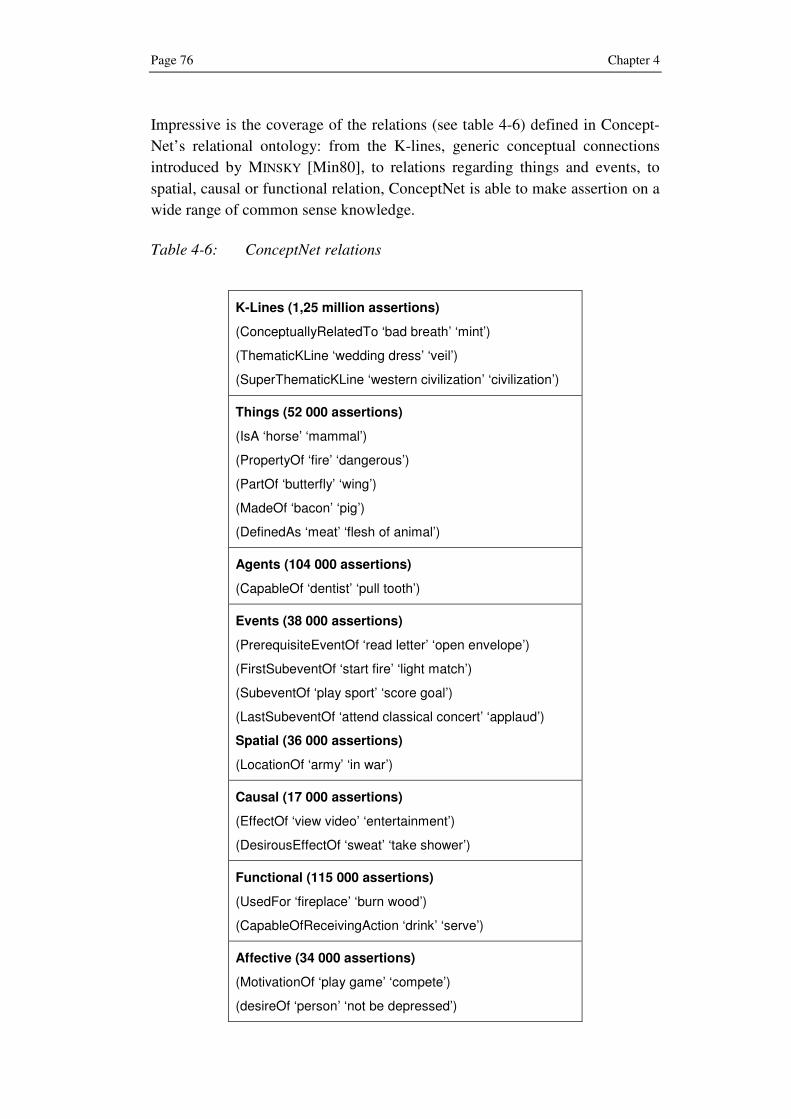
Page 76 Chapter 4
Impressive is the coverage of the relations (see table 4-6) defined in Concept-
Net’s relational ontology: from the K-lines, generic conceptual connections
introduced by MINSKY [Min80], to relations regarding things and events, to
spatial, causal or functional relation, ConceptNet is able to make assertion on a
wide range of common sense knowledge.
Table 4-6: ConceptNet relations
K-Lines (1,25 million assertions)
(ConceptuallyRelatedTo ‘bad breath’ ‘mint’)
(ThematicKLine ‘wedding dress’ ‘veil’)
(SuperThematicKLine ‘western civilization’ ‘civilization’)
Things (52 000 assertions)
(IsA ‘horse’ ‘mammal’)
(PropertyOf ‘fire’ ‘dangerous’)
(PartOf ‘butterfly’ ‘wing’)
(MadeOf ‘bacon’ ‘pig’)
(DefinedAs ‘meat’ ‘flesh of animal’)
Agents (104 000 assertions)
(CapableOf ‘dentist’ ‘pull tooth’)
Events (38 000 assertions)
(PrerequisiteEventOf ‘read letter’ ‘open envelope’)
(FirstSubeventOf ‘start fire’ ‘light match’)
(SubeventOf ‘play sport’ ‘score goal’)
(LastSubeventOf ‘attend classical concert’ ‘applaud’)
Spatial (36 000 assertions)
(LocationOf ‘army’ ‘in war’)
Causal (17 000 assertions)
(EffectOf ‘view video’ ‘entertainment’)
(DesirousEffectOf ‘sweat’ ‘take shower’)
Functional (115 000 assertions)
(UsedFor ‘fireplace’ ‘burn wood’)
(CapableOfReceivingAction ‘drink’ ‘serve’)
Affective (34 000 assertions)
(MotivationOf ‘play game’ ‘compete’)
(desireOf ‘person’ ‘not be depressed’)

Artificial Intelligence Approaches Page 77
4.3.2 Task and Domain Ontology
Upper Ontologies, as introduced in the previous section, are generic, widely
applicable and shareable; however, Ontology can also be seen as domain spe-
cific and deal with just a small portion of the knowledge domain. Such ap-
proach [MSI96] considers ontology built up by two separate parts:
• Task ontology, which characterizes the computational architecture of a
knowledge based system that performs a task;
• Domain ontology, which characterizes knowledge of the domain where
the task is performed
Task ontology describes inherent problem solving structure of existing tasks
domain-independently. It is obtained by analyzing task structures of the real
world by means of four kinds of concepts:
1. Task roles: roles played by the domain objects in the problem
solving process
2. Task actions: activities appearing in the problem solving process
3. States of the objects
4. Other concepts specific to the task
Table 4-7: Concepts included in task ontology for a scheduling task
Task roles “Scheduling recipient” “scheduling resource”, “due date”, “con-straints”, “goal”, “priority”
Task actions “assign”, “classify”, “pick-up”, “select”, “neglect”
States “unassigned”, “the last”, “idle”
Other “constraint satisfaction”, “constraint predicates”, “attribute”
A domain ontology (or domain-specific ontology) models a specific domain, or
a part of the target world. It represents the particular meanings of concepts as
they apply to that domain. For example the concept card has different mean-
ings: an ontology about the domain of games would model the "playing card"
meaning of the concept, while an ontology about the domain of computer
hardware would model the "punch card" and "video card" meanings.
Many domain ontologies have been already developed in different domains: for
example, in the medical domain, with the Gene Ontology [AL02], the Protein
Ontology [SDC+05] and the foundational model of anatomy [RM03], in the

Page 78 Chapter 4
botanic domain with the Plant Ontology [PO02] as well as in the industrial
domain, with the modeling of an industrial plant [MKS+00] and with the Proc-
ess Specification Language (PSL), which is the ISO Standard 18629.
4.3.3 Ontology and Training
The use of Ontology approaches in the training domain has begun in the sec-
ond half of the 90s [JIM96], [JIM+97]: in particular one task and domain on-
tology approach [CHJ+98] has inspired the research proposed in this book. The
research work has led to the development of SmartTrainer, an ontology-based
intelligent authoring tool whose aim is to train operators of an electric power
network to recover power transmission as soon as an accident happens. The
system lets at first the operator looking for a solution to the problem: according
to the mistakes made by the operator during this operation path, the most ap-
propriate teaching strategy to teach the knowledge behind the practice is se-
lected by the system. Training is here meant as “computer-based training”
where the trainee interacts with a computer-generated scenario; no support for
graphics or 3D animation and interaction is provided.
Ontology plays in the training authoring tool the following important roles:
• formalizing the construction process of the intelligent training systems
• providing primitives that facilitate the knowledge description at the
conceptual level
• constructing explicit models
• providing axioms for the construction of intelligent training systems
Different kinds of ontologies are used in SmartTrainer, the most important of
which can be summed up as follows:
• Domain Ontology, which specifies the conceptual vocabulary and the
representational framework for classes of a domain
• Teaching Strategy Ontology, which provides the author with a mean of
model its teaching experiences
• Learner Model Ontology, which helps the author to represent a suitable
learner model mechanism so that the system can behave adaptively to
the learner’s state
Ontology is therefore useful not only to model different domains, which repre-
sent the target of the training, but also different kind of audience, i.e. trainees
or learners, each of which has its own background and its need of information.

Artificial Intelligence Approaches Page 79
4.4 Ontology as Knowledge-base for the automatic Gen-
eration of 3D Computer Animations
The considerations contained in the previous section have led to the choice of
an ontology as knowledge-based core for the intelligent authoring of 3D an-
imations; it allows in fact the necessary link between linguistic elements and
the corresponding concepts of a training scenario.
Due to its modular structure, ontology can be easily extended through addi-
tional domain ontologies that embed domain knowledge and vocabulary as
well as relations between the concepts; this structured knowledge can be then
used to describe technical parts or assemblies from a conceptual point of view
and to link such description to the corresponding 3D model, previously devel-
oped and stored in a repository. The use of Ontology in order to create interac-
tive graphic environments for product presentation can also be found in litera-
ture [TNT+04].
At the same time it is possible the characterization within the ontology of the
action verbs that derive from natural language descriptions: each action can
then be translated from a textual to a conceptual representation by means of
knowledge of the movements and transformations connected to every action.
Actions can also results in different transformations according to the target
object.
In addition ontology is also able to manage different kind of end user roles and
their need of information by managing the according view of the 3D model and
its level of detail within the animation.
The ontology approach represents then the selected artificial intelligence ap-
proach and constitutes the core of the developed process model, which is intro-
duced in the following section.


Ontology-driven Generation of 3D Animations Page 81
5 Ontology-driven Generation of 3D Animations
The evaluation of state-of-the-art approaches in literature of computer graphics
as well as of artificial intelligence has shown that no approach, which is able to
generate 3D animations for training purposes starting from natural language
instructions, has been developed so far. The closest text-to-scene approach,
Confucius, showed in section 3.3.3, deals with animation of humanoids starting
from natural language descriptions and it is therefore not useful for the training
domain in industrial scenarios.
In addition, current commercial software solutions demand the creation of 3D
animations to specialized 3D artists, not offering any possibility of automation
of the actions that characterize the animation itself: only in one case, a “wizard-
like” approach has been found in order to associate predefined actions to spe-
cific objects. However, this possibility to use predefined animation atoms does
not prevent the arising of various problems: on the one hand, the identification
of the correct objects, which take part in the training task, is left arbitrarily to
the author. On the other hand, no indication on how the parts interact with each
other, during the animation, is given: for example, the author does not know a
priori which parts are involved and how they move, after pressing the start but-
ton of a mechanical device.
The analysis performed so far has led to a call for action in order to give to the
research area a structured and flexible approach, which can be extended and
reused for multiple domains. The result of this process is the development of a
method, which proposes the use of an ontology, whose features have been ana-
lyzed in the previous section, as a semantic knowledge base. As preliminary
step the development of the ontology core is described in the following sec-
tions.
5.1 Basic idea
Textual communication is together with voice the most used mean to deliver
information: this is valid not only in everyday life but also in industrial envi-
ronments, where textual communication from e-mails to instruction manuals is
massively widespread. It is therefore reasonable imagining of text-based de-
scriptions of training sequence since most of existing training material is al-
ready written down in a text form and can therefore be reused and translated
into a more intuitive 3D animation.
The basic idea (see figure 5-1) is to extract information from training se-
quences, in the form of natural language texts, and convert it into an animation
script, which through the corresponding viewer shows the required animation.

Page 82 Chapter 5
In order to achieve this aim an intelligent approach needs to be developed: the
proposed method requires a first understanding of the structure of a generic
training sentence, by means of natural language parsing techniques. Once the
single elements are found and labeled at a phrase level (noun phrase, verb
phrase) as well as at a word level (noun, verb, adjective or adverb), also the
meaning of each element, has to be investigated. This second part of the
method is performed by an ontology core, whose aim is the definition of gen-
eral and domain knowledge in terms of meaning, to be coupled to the natural
language elements.
Figure 5-1: Overview of the basic idea of the proposed approach
In addition, since the aim is the generation of 3D animations for training pur-
poses, the method needs to access a repository of existing 3D models. Such 3D
objects are eventually animated in the virtual environment through animation
techniques that represent a series of actions previously described by natural
language instructions.
5.2 Ontology Core
Ontology plays in the proposed approach a central role: it is the link between
linguistic elements and the corresponding concepts to be displayed in the 3D
animation. Once these concepts are identified in the knowledge base, the object
or action counterparts are respectively recalled or created, in order to build up
the basis of the requested 3D animation.
In section 4.2 some notions about Ontology and its different kinds have been
given. One of the main problems occurring with ontology is that its develop-
ment, starting from scratch, is a very time consuming task. Furthermore it must
3D Models
Training request input
Customized animation
Script generator
Ontology core
Action Ontology
Part Ontology
Natural language parsing

Ontology-driven Generation of 3D Animations Page 83
be by definition shared by the community in order to assure extensibility and
reusability for different purposes and domains. These conclusions suggest the
necessity to use an existing “upper ontology” as a mainstay of the ontology
core, instead of developing a completely new one.
The proposed approach is made up of two different levels characterizing the
ontology (see figure 5-2): at a higher level, the use of an upper ontology is
foreseen, completed by multiple domain ontologies, which supply the neces-
sary low level knowledge for the domain of training. The Upper Ontology con-
tains general purpose knowledge, vocabulary and relations, able to get a first
basic overview of the content of a generic training sentence. Furthermore it
defines also a common framework, which paves the way for the development
of the more specific domain ontologies, which cover specific concepts of a
well defined domain, e.g. a car ontology or an airplane ontology for instance,
both from the components point of view and from the actions performed
through them: they include in fact, concepts of technical parts, e.g. “lathe” or
“spindle” as well as action verbs related to the parts. Domain ontologies, each
for a specific domain, can be seen analogously to plug-and-play components,
which offer more functionalities (knowledge) once connected to the main de-
vice (upper ontology) and once the communication language, defined by the
framework is shared.
Figure 5-2: Upper Ontology and Domain Ontologies
The next sections define how the ontology core is structured and subdivided: at
first, the upper ontology is introduced, together with its characteristics and its
main purposes. Then, the structure of a generic domain ontology and its com-
ponents are presented.
Upper Ontology
Car Ontology Airplane Ontology Manufacturing Machine Ontology

Page 84 Chapter 5
5.2.1 Upper Ontology
An upper ontology contains a basic understanding of domain-independent con-
cepts and relations, necessary to deal with parts of training sequences that do
not belong to a specific problem domain.
Its knowledge is defined through a network structure, made up of four basic
elements, shown in the table 5-1: they include the “class” and “individual”
concepts, already introduced in chapter 4, the “attribute” property and the rela-
tions between the elements, i.e. “IsA” or “PartOf”, which do not need to be
defined through additional concepts.
Table 5-1: Basic elements of the upper ontology
Concept Description
Class Union of classes or individuals that share the same characteristics.
Attribute Characterization of a concept through attributes that have a name and value.
Individual Single entity, instance of a higher level class.
Relation Relation between concepts through attributes or functions.
The basic elements defined above characterize all other concepts contained in
the upper ontology as well as in eventual domain ontologies: thus, a concept
like “Device” can be described by
• an upper class, e.g. “Artifact”
• a set of lower classes, e.g. “Machine”, “TransportationDevice” or “En-
gineeringComponent”,
• attributes, e.g. “Date”, “Number”, “Time”, “Property”
• relations, e.g. “hasPurpose”, “connects”, “refers to”.
Individual or instances represent the single elements of the population, i.e. the
leaves of the hierarchical tree that refer to a class: a feasible instance of “De-
vice” can be represented by the “Computer” or “Shaver” concepts.
Another characterization of concepts describing common elements is obtained
by the additional classes “physical” and “abstract”, necessary in order to filter
elements, represented through the corresponding 3D models from abstract con-
cepts, which cannot be visualized but can be described through textual or vis-
ual information.

Ontology-driven Generation of 3D Animations Page 85
Dealing with natural language, an extremely important knowledge domain that
the upper ontology must embed is represented by the various verb forms,
which can be found in a generic sentence: identifying that the verb forms “re-
moves” or “removed” refer to “removing” is essential for the feasibility of the
proposed approach.
It is also an advantage including in the upper ontology notions of “common-
sense” knowledge. With “commonsense” is usually denoted knowledge shared
by human beings and deriving from every day’s experience. This comprehends
common verbs (“opening”, “removing”) and words (“device”, “car”) as well as
their relations (a car has a Chassis, an Engine, a Dashboard, etc.).
Another feature of the upper ontology is the definition of a common framework
for the development of domain ontologies and establishes a way to describe
concepts recursively, linking sub-concepts to higher level ones, through the
language used33
, e.g. OWL [DS04-ol], KIF or CycL, to enter knowledge.
The upper ontology, with a wide knowledge in different domains, represents a
good starting point but it is not able to catch all the meanings included in a ge-
neric training session. It is difficult finding in a general ontology, very specific
concepts like “Lathe” or “Fuselage”, “Finishing” or “Assembling”. For more
detailed concepts that are not included in the upper ontology the development
of one or multiple domain ontologies is required.
5.2.2 Domain Ontology
Ontology represents a conceptualization of the target world; this is valid not
only for the representation of generic macro concepts, like “device” or “open-
ing”, but also for the modeling of more specific concepts within a defined sub-
domain. In order to have a full coverage of the training domain, the use of one
or more domain ontologies is necessary.
In the proposed approach, a generic domain ontology is thought to be com-
posed by two different knowledge sub-domains:
• “part ontology”, specifying technical parts through a hierarchy of
classes and relations between them;
• “action ontology”, comprehending the conceptualization of a series of
actions executed in a real training environment.
33 An Ontology language is usually first order predicate calculus, also referred to as first order logic (FOL); it is a system of deduction that extends propositional logic by the ability to express relations between individuals more generally.

Page 86 Chapter 5
Part ontology constitutes the domain of nouns, included in generic training
sessions; it specifies technical parts, target of training sessions, and their rela-
tions not defined in the upper ontology. Aim of the part ontology is to allow the
identification of technical parts and their eventual representation in the 3D
animation.
Action ontology represents the domain of the verbs, as well as past participles,
which characterize the actions included in training sessions; aim of the action
ontology is to transform natural language actions into a formal representation
for the animation of the virtual objects. In addition, the action ontology is able
to characterize different actions for the same verb according to the target ob-
jects they refer to.
5.2.2.1 Domain Ontology Development
While for the upper ontology the use of an already existing one is reasonable,
since it must embed a wide knowledge and be shared by the community, the
domain ontology must be developed “ad hoc”; once defined the domain of the
training, the domain ontology can be populated by concepts that can be found
in existing training material, like an instruction manual. In order to develop the
domain ontology, the following sequence of tasks has to be executed:
• Definition of classes and their hierarchy
• Definition of attributes
• Definition of the relations between concepts
• Populating classes with individuals
The first step is the definition of classes for the target concepts and their hier-
archy. Main strategies, used in the proposed approach, for this task are:
• Top-down, starting with the definition of the most general concepts and
eventually their specializations: e.g. MechanicalDevice > Drilling-
Machine > DrillPress.
• Bottom-up, starting with the definition of the most specific classes and
eventually grouping them in subclasses: e.g. DrillPress > Drilling-
Machine > MechanicalDevice
• A combination of the previous ones, starting with one high level con-
cept, like MechanicalDevice, and a specific one, like DrillPress, and
then defining the class in the middle, e.g. DrillingMachine.

Ontology-driven Generation of 3D Animations Page 87
The defined classes need to be ordered in a hierarchical form in order to build
the taxonomy, which is an essential part of every ontology. In addition, this
guarantees an easier further development or reuse of the ontology.
In order to avoid the creation of duplicates and eventual misunderstandings,
just the concepts, which are not exhaustively defined in the upper ontology,
should be created. This process is therefore heavily dependent on the chosen
existing upper ontology and on the knowledge it embeds.
Having defined the necessary classes and their hierarchy, some attributes need
to be entered to characterize each class. An attribute is made up of a name (e.g.
number-of-wings) and a value (in the considered case exactly two for an air-
plane). If attributes are not defined, than it is no more possible speaking about
ontology but just about taxonomy (see figure 5-3); when an attribute has been
defined for a class, it remains valid also for all the subclasses.
Figure 5-3: Extract of a mechanical device taxonomy
A fundamental role is also played by relations, representing the links that con-
nect classes together. A detailed description of the proposed relations, in addi-
tion to the ones defined in the upper ontology, is given in the following sec-
tions. They derive from a selection of the relation-types used in the ConceptNet
project.
The elements representing the leafs of the ontology hierarchy are the individu-
als, also known as instances: they include physical objects as well as abstract
concepts included in a class of the target domain. For example, the “car” con-
Mechanical device
Milling machine
Drilling machine
Lathe
Drilling press
Hammer drill
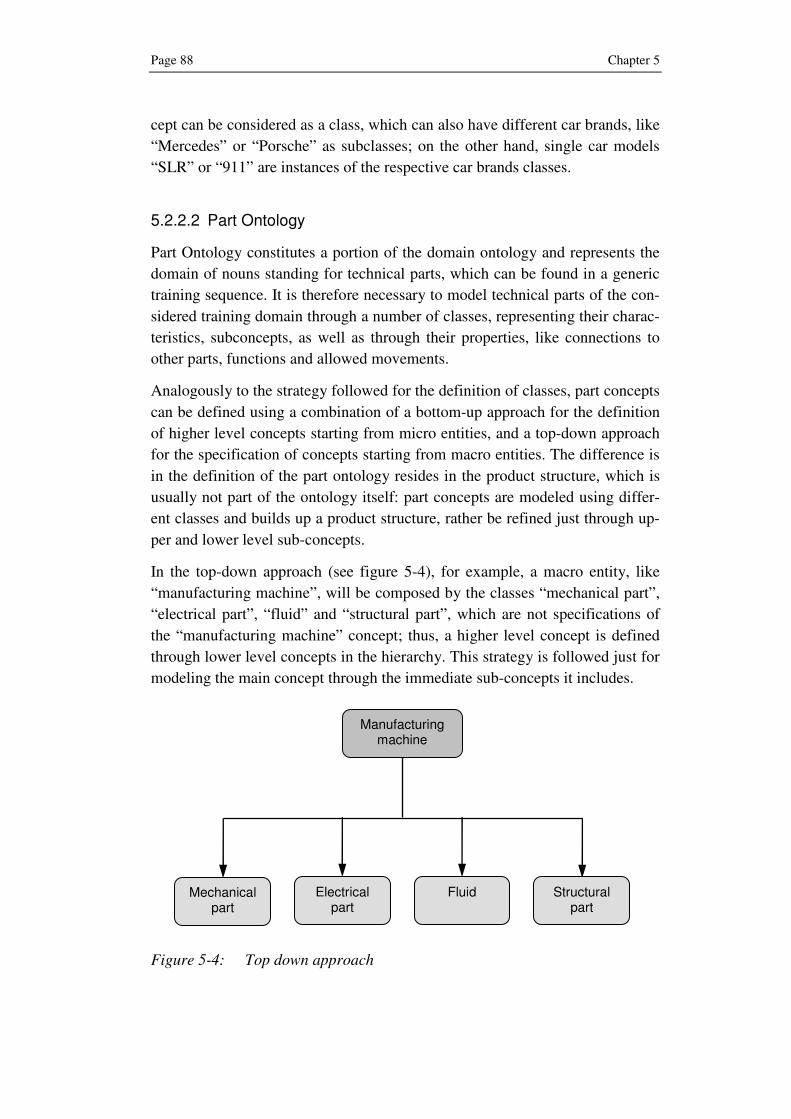
Page 88 Chapter 5
cept can be considered as a class, which can also have different car brands, like
“Mercedes” or “Porsche” as subclasses; on the other hand, single car models
“SLR” or “911” are instances of the respective car brands classes.
5.2.2.2 Part Ontology
Part Ontology constitutes a portion of the domain ontology and represents the
domain of nouns standing for technical parts, which can be found in a generic
training sequence. It is therefore necessary to model technical parts of the con-
sidered training domain through a number of classes, representing their charac-
teristics, subconcepts, as well as through their properties, like connections to
other parts, functions and allowed movements.
Analogously to the strategy followed for the definition of classes, part concepts
can be defined using a combination of a bottom-up approach for the definition
of higher level concepts starting from micro entities, and a top-down approach
for the specification of concepts starting from macro entities. The difference is
in the definition of the part ontology resides in the product structure, which is
usually not part of the ontology itself: part concepts are modeled using differ-
ent classes and builds up a product structure, rather be refined just through up-
per and lower level sub-concepts.
In the top-down approach (see figure 5-4), for example, a macro entity, like
“manufacturing machine”, will be composed by the classes “mechanical part”,
“electrical part”, “fluid” and “structural part”, which are not specifications of
the “manufacturing machine” concept; thus, a higher level concept is defined
through lower level concepts in the hierarchy. This strategy is followed just for
modeling the main concept through the immediate sub-concepts it includes.
Figure 5-4: Top down approach
Manufacturing machine
Mechanical part
Electrical part
Fluid
Structural part

Ontology-driven Generation of 3D Animations Page 89
On the other hand, in the bottom-up approach (see figure 5-5), concepts of
smaller parts, like “Motor”, “Motor Gear” and “Motor connecting Flange”, can
be considered as “atomic”: they can be seen as atoms, building up a higher
level concept. Their association, together with other basic concepts, like “Fas-
tener”, builds up a higher level concept, like “Motor Group”.
Figure 5-5: Bottom-up approach
The approach followed for the definition of the concepts automatically builds
up a hierarchy of the concepts: the main concept can be found on the top of the
hierarchy tree, while the connected components are one step down. The leaves
of the hierarchy tree are represented by the instances of the components.
Concepts populating part ontology are further specified not only by means of
sub-concepts but also by relations, which can regard different levels of knowl-
edge: on a conceptual level, on a spatial level and on a functional level. The
used relations on the conceptual level, including a brief description, are shown
in the table 5-2.
Table 5-2: Relations on conceptual level
Level Relation Description
Conceptually-RelatedTo
A link to other concepts, to whom the concept refers to
DefinedAs Formal or informal explanation of the concept
IsA Abstraction of the concept through its upper classes
Conceptual
partOf Part-whole relation
Motor group
Motor
Motor gear
Motor flange
Fastener

Page 90 Chapter 5
While “IsA” and “PartOf” represent the already introduced hyperonymy and
meronomy relations, the “ConceptuallyRelatedTo” is a very important and
powerful link between concepts, which are not directly connected. For exam-
ple, the part ontology concept “button” can be thought as conceptually related
to the concept “pushing”, even if included in the action ontology. This paves
the way to a more intelligent management of the objects and their correspond-
ing actions. The “DefinedAs” relation supplies additional information about the
concept and can be used in case of multiple meanings or for disambiguation
purposes.
Parallel to the definition at a conceptual level, parts must be also characterized
at a spatial level (see table 5-3), in order to characterize the physical aspects of
every defined part. In addition, parts can also be characterized by their func-
tionalities; what can be done with that part? Or, which actions the part is able
to receive?
Table 5-3: Spatial and functional relations
Level Relation Description
LocatedIn Location of the part inside higher level concepts
ConnectedTo Eventual connection to other parts
HasDimension Dimensions of the part
Spatial
AllowedMovement Allowed movements for the part
UsedFor Action that can be done through or with the part Functional
CapableOf-ReceivingAction
Action that can be received by the part
An example can help to better understand the introduced relations: on a con-
ceptual level the concept “drill” is described by the “IsA” relation as a “me-
chanical device”, can be “DefinedAs” “a tool used for boring holes in objects
by means of a rotating sharp-edged cylindrical bit” and can be therefore con-
nected to the “boring”, “hole” and “drill bit” concepts by the ConceptuallyRe-
latedTo relation. In this case the main concept is the “drill” itself so no “part
of” relation is defined. On the functional level, the concept is connected by the
“UsedFor” relation to the concepts “boring” and “drilling” among other actions
and also to the concepts “holding”, “grasping” or “gripping” by “CapableOf-
ReceivingAction”. To conclude the example, the “drill” has some dimensions
“length”, “width” and “depth” to be derived by the instance of the concept and

Ontology-driven Generation of 3D Animations Page 91
allows a “three dimensional movement”; differently the “drill bit” concept al-
lows the “translation on z axis”, considering the z axis coincident with the axis
of the bit itself.
The actions specified in the functional relations establish also a link to the ac-
tion ontology, where each action concept is refined through a series of trans-
formations, which constitute the basis for the further representation of the ac-
tion in the virtual scene.
5.2.2.3 Action Ontology
Action ontology is required to describe action verbs, comprehending training
or maintenance tasks, which are partially defined or not defined at all in the
upper ontology.
Verbs are grouped in classes, in their “–ing” form, e.g. “removing” for “re-
move”. The nature of each verb can be essentially of two kinds: physical or
abstract. A verb can be defined as “physical” if it implies a movement of the
object, which receives the action, or a change in its state: the verb “connect”,
for instance, refers to the connection of one object with another one. On the
other hand, a verb is abstract when the action is performed without changing
the state of the target object: the verb “locate” implies that the subject looks for
an object, without touching, moving and therefore interacting with it. Each
verb can be therefore subdivided into the abstract and physical subclasses, ac-
cording to its nature.
Physical verbs can be further subdivided in three sub-classes (see figure 5-6)
according to the kind of action performed. Verbs where the action regards just
one entity, human or object, without any interaction with other entities, are
grouped into the “pure action verbs”: this is the typical situation of autonomous
movement, like a man walking or a box opening automatically. Such verbs
play a marginal role in training situations, but the class has been included for
completeness of the physical verb domain. Much more frequent is the case of
interaction of the subject, usually human, with an inanimate object, like “turn-
ing on a machine” or “substituting a damaged part”. The “action on object”
class does not contain verbs, like “locate” or “examine”, which even if refer-
ring to an object, do not directly interact with it. The same action can some-
times be more specific and require a third “actor”, indicated usually through a
preposition, like “with” or “through”: it is the case of operations, which can be
done just with a tool, like cleaning a sensor with a cloth or tightening bolts with
a wrench.

Page 92 Chapter 5
Figure 5-6: Taxonomy of the Action Ontology
This further specification of physical verbs is necessary to distinguish different
kinds of action that are to be represented in the animation: to “Pure Action”
verbs correspond to simple transformations or movements of an element, for
“Action on Object” verbs the virtual camera must be close to the related object,
while the additional recalling of external 3D model of the tool is necessary for
“Action with tool” verbs.
Abstract verbs represent for their own nature something that cannot be visual-
ized through actions: for example, the verb “locate” or “search” do not add any
additional information on the performed action, which remains basically a vis-
ual search. However, they can cover important roles in the definition of a ge-
neric training sentence. The class includes also static verbs, for example the
verb “to be” in “the pen is on the table”, which indicate position of the objects
in the virtual environment.
Each verb is characterized by a set of relations, defined in table 5-4, which de-
rive from the ConceptNet research approach. They describe similar actions
associated to the concept through the “KindOf” relation as well as the contrary
of the action itself, through the “HasContrary”; this feature allows the connec-
tion of the action concept to its contrary, to be used for example in assembly
and disassembly tasks. The relations “HasDomain” and “HasRange” describe
respectively the roles able to perform that action and the range of concepts tar-
get of the action itself. The relation “duration” represents a critical point, also
for the representation of the action in the virtual environment; it influences in
fact the speed of the action, which must be as close as possible to the real dura-
tion of the action
Physical Verb
Abstract Verb
Pure Action
Action with Tool
Action on Object
Action Ontology

Ontology-driven Generation of 3D Animations Page 93
Table 5-4: Action Ontology Relations
Relation Description Value/Range
KindOf Definition of similar actions through upper class Verb
HasDomain Allowed role user that performs the action Role
HasContrary Antonym of the considered concept Verb
HasRange Allowed objects that are target of the action Object
LocationOf Eventual location for the happening of the action Place
EffectOf Effects of the action Movement
MotivationOf Cause for the action to take place Task
Duration Estimated time for the completion of the action Time
The relations defined in the table above establish a link between ontology and
the formal description of the animation: each verb can be coupled through the
“EffectOf” relation to one of the following specific commands, together with
their necessary parameters:
• Movein/Moveout: translation, respectively approaching or leaving the
target object, on a specified axis for a length
• Be: spatial position of a point or an object
• Rotate: rotation on the specified axis and for a determined angle
• Scale: scaling factor for the target object
Those commands represent the results of the translation of a natural language
action into the corresponding formal description.
5.2.2.4 Spatial Prepositions
A locative expression is an expression involving a locative prepositional phrase
together with whatever the phrase modifies (noun, clause, etc.). The simplest
type of locative expression is composed of three constituents: the spatial prepo-
sition and two noun-phrases. For example, in “the button on the control panel”,
the button is the subject of the preposition, and the control panel is the object.
The subject refers to the located entity, the object to the reference entity. Some
locative expressions use a clause as subject of the preposition.

Page 94 Chapter 5
Spatial prepositions fall into two categories: some are primarily static (e.g. at,
in, under), others primarily dynamic (to, from, via). But static prepositions can
be used in dynamic contexts, like in “the cat ran under the bed”, and dynamic
can be used in static contexts, like in “the lamp is two feet from the wall”. The
proposed approach considers just the basic topological prepositions (at, on, in),
together with their corresponding set of triples, including the prepositions used
in the approaching or leaving the target region [Her86]:
• Point: to, at, from
• Surface: on to, on, off
• Volume: into, in, out of
Path prepositions like “through”, “across”, “around” or “along” are not consid-
ered in this research approach but can be integrated in a further development.
According to the defined kinds of spatial prepositions, the action ontology is
able to match the transformations defined in table 5-5, according to the kind of
preposition and to the related action or static verb.
Table 5-5: Spatial prepositions
Preposition Kind Conditions Related to Transformation
To Action Verb MOVEIN ( ) ( )000 ,,,, zyxzyx →
At Static Verb BE ( ) ( )000 ,,,, zyxzyx ≡
From
Point
Action Verb MOVEOUT ( ) ( )zyxzyx ,,,, 000 →
On to Action Verb MOVEIN ( ) ( )000 ,,,, zyxzyx →
On Static Verb BE ( ) ( )000 ,,,, zyxzyx ≡
Off
Surface
Action Verb MOVEOUT ( ) ( )zyxzyx ,,,, 000 →
Into Action Verb MOVEIN ( ) ( )000 ,,,, zyxzyx →
In Static Verb BE ( ) ( )000 ,,,, zyxzyx ≡
Out of
Volume
Action Verb MOVEOUT ( ) ( )zyxzyx ,,,, 000 →

Ontology-driven Generation of 3D Animations Page 95
Spatial prepositions are then able to connect static verbs to a well defined posi-
tion of the related object in the virtual environment. On the other hand, they are
able to define also a kind of motion, defined as Movein or Moveout, respec-
tively for approaching or leaving the reference object.
5.2.2.5 Events
So far technical parts and actions have been considered separately in two dif-
ferent ontologies in order to guarantee the advantages deriving by the ontology
approach, like knowledge adding, sharing and reuse. However, additional
benefits can derive from joining concepts of both ontologies in the definition of
small knowledge portions that are able to represent sequences of operations.
The combination of the part and action ontologies within a common domain
ontology allows in fact the management of events: an event can be defined as a
generic task, e.g. “tire change”, made up of a sequence of subtasks or sub
events, necessary to fulfill the main task. Sub events can be then recursively
defined as “atomic” actions, which can be also reused for different domains or
combined together in arbitrary sequences. To achieve this result, another series
of relations regarding events and sub events is introduced:
• FirstSubeventOf
• SubeventOf
• LastSubeventOf
• PrerequisiteEventOf
For example, the procedure for the “tire change” event in a car can be entered
in the “car” domain ontology, though a sequence of sub events, like in the fol-
lowing example:
1. “Loosen” AND “lug nuts” (FirstSubeventOf TireChange)
2. “Remove” AND “lug nuts” (SubeventOf TireChange)
3. “Pull” AND “the tire” AND “off the car”
(SubeventOf TireChange)
4. “Place” AND “the spare” AND “on the car”
(SubeventOf Tire Change)
5. “Put on” AND “lug nuts” (LastSubeventOf Tire Change)
However, some events were not possible unless some prerequisites are satis-
fied. In the situation mentioned above, they correspond to:
• “Stop” AND “the car” (PrerequisiteEventOf Tire Change)

Page 96 Chapter 5
• “Set” AND “the parking brake” (PrerequisiteEventOf Tire Change)
• “Lift” AND “the vehicle” AND “off the ground”
(PrerequisiteEventOf Tire Change)
Recursively also prerequisite events, like the “auto lifting”, can be described
through a sequence of sub events.
Events and sub events, as well as any sequence between them, are included in a
part of the domain ontology, separated and independent from the part and ac-
tion ontologies. This allows the management of task sequences, which other-
wise could be very difficult just considering the part and action ontologies.
5.2.2.6 Roles
Together with the definition of events, an additional and important category to
be introduced in the domain ontology is represented by the end user roles, tar-
get of the training sessions for that specific domain. The proposed approach is
able to manage, through the ontology, different end user roles, the most com-
mon of which are:
• Maintenance staff
• Operation workers
• Assembly workers
• Salesman
Every defined role needs a different kind of information, even regarding the
same target product. For example, maintenance staff requires very detailed
information about the whole target object, like the location of electric cables in
a machine, which are not needed by other roles. This requirement is managed
by coupling to each role, different levels of detail of the target object within the
virtual scene: according to the considered role, some layers of the 3D model
containing elements of a specific knowledge domain (circuits, pipes, etc.) can
in fact be set visible or invisible and at the same time the management of the
virtual camera can display an overall or close view of the training object.
The role of the end user within the training session can also be inferred from
the training sequence itself since concepts can be linked to roles through the
hasDomain relation in the action ontology.

Ontology-driven Generation of 3D Animations Page 97
5.3 Overview of the developed Method
The basic idea for the proposed research approach is the use of ontology in
order to understand natural language training sessions and to translate it into
the corresponding animation; the ontology core is made up of an existing upper
ontology, as a first high level knowledge base, which acts also as a common
framework, and one or multiple domain ontologies, which represent through
parts and actions, the target world of a generic training scenario.
In order to provide a homogeneous method, which is able to satisfy all the re-
quirements for the intelligent authoring of 3D animations for training purposes,
a process model has been developed. It is represented in figure 5-7 as a
Phase/Milestone diagram: to each phase or milestone are associated some tasks
to be executed in order to obtain the corresponding results, shown on the right.
Figure 5-7: Developed Process Model

Page 98 Chapter 5
The proposed method consists of five phases, starting with a generic training
request, which has to be entered in a text form by the customer or by the end
user. Once entered, this input is at first parsed, labeled and eventually matched
to the concepts defined in the ontology core.
The process model output is a script, a text description of the content that acts
as a “screenplay” of the animation and that can be visualized through the use of
the appropriate viewer. The next sections give a detailed description of each
phase building up the process.
5.4 Phase 1: Training Request
Before starting the authoring of a general 3D animation, a 3D artist in a tradi-
tional approach needs to understand the topic of the animation itself: which 3D
models are involved, where they are placed, which actions are taking place and
which relations between them, i.e. sequence or duration of the tasks, must be
observed. Usually this preliminary analysis is done in cooperation with special-
ized technical staff, which supports the authoring process with the necessary
technical knowledge of the considered domain.
Figure 5-8: Extract from a generic instruction manual
Paper-based documentations, like instruction manuals (see figure 5-8) or as-
sembly procedures, contain a detailed description of maintenance, assembly or
operation tasks to train non-specialized people, which have not enough confi-

Ontology-driven Generation of 3D Animations Page 99
dence with the involved parts. They represent 3D objects in a static two-
dimensional way; thus, it is not immediate to visualize neither which is the
correct part involved nor how they interact between them.
The approach of every instruction manual can be considered as “task cen-
tered”: the topic of the task is introduced by the title itself, and then a list of
subtasks, to be executed in a given sequence, explains in detail the subtasks to
be executed. Analogously, the approach followed in the developed method uses
a title for the identification of the topic and a sequence of the single steps,
building up the training session. Two main scenarios can be reasonably fore-
seen for the training animation authoring:
• A sequence of subtasks building up the training content is already
available, e.g. an instruction manual, paper-based training material
• No content is available and the training sequence must be created from
scratch, entering a main topic title and the corresponding list of tasks
In the first scenario, the file containing the sequence is passed as it is to the
following step of the method, the natural language parsing, for the identifica-
tion of the structure and of the syntax of each sentence. In case no existing ma-
terial is available, the desired training sequence must be created “ad hoc” from
scratch. This can be done as described in the next sections in a text form, with
the definition of a title, which corresponds to the main topic of the training
session, followed by the sequence of single subtasks.
5.4.1 Topic of the Training Request
The first content to be provided could seem at first very trivial but it is at the
same time very important since it delimitates the training knowledge about the
considered domain. The title of the training request must be very specific and
contain accurate information about the target, to avoid possible misunderstand-
ings, which are very common in natural language descriptions. Titles like “ma-
chine installation” or “car maintenance” are too vague, thus unable to allow the
identification of well-defined tasks. Furthermore they could not assure, for ob-
vious reasons, the reusability of the overall approach.
The necessary content for a well defined and exhausting training request’s title
is defined by the following elements:
• Action
• Main concept
• Main instance
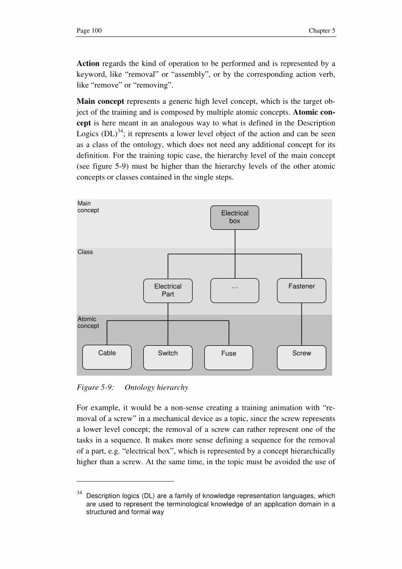
Page 100 Chapter 5
Action regards the kind of operation to be performed and is represented by a
keyword, like “removal” or “assembly”, or by the corresponding action verb,
like “remove” or “removing”.
Main concept represents a generic high level concept, which is the target ob-
ject of the training and is composed by multiple atomic concepts. Atomic con-
cept is here meant in an analogous way to what is defined in the Description
Logics (DL)34
; it represents a lower level object of the action and can be seen
as a class of the ontology, which does not need any additional concept for its
definition. For the training topic case, the hierarchy level of the main concept
(see figure 5-9) must be higher than the hierarchy levels of the other atomic
concepts or classes contained in the single steps.
Figure 5-9: Ontology hierarchy
For example, it would be a non-sense creating a training animation with “re-
moval of a screw” in a mechanical device as a topic, since the screw represents
a lower level concept; the removal of a screw can rather represent one of the
tasks in a sequence. It makes more sense defining a sequence for the removal
of a part, e.g. “electrical box”, which is represented by a concept hierarchically
higher than a screw. At the same time, in the topic must be avoided the use of
34 Description logics (DL) are a family of knowledge representation languages, which are used to represent the terminological knowledge of an application domain in a structured and formal way
Electrical box
Electrical Part
Fastener
Cable
Fuse
Switch
…
Screw
Atomic concept
Class
Main concept

Ontology-driven Generation of 3D Animations Page 101
concepts, which are positioned in a level higher than the target one. If the
atomic concept is represented in the topic by the object “drill bit”, then it
would be wrong referring just to the higher concept “drill”.
Main instance adds complementary information, necessary to unambiguously
identify the target of the training; it denotes the “conceptual” location, rather
than its pure position, by specifying the instance, and not the class, of the train-
ing object. For example, the “Tire change for a car” topic specifies nothing
about the kind of the considered car: is it a SUV35
or a city car? A Mercedes or
a Porsche? Those are still classes but the car models are instances of the car
brand class. No ambiguity is possible if the instance is specified, like in case of
the topic “Tire change for a Porsche 911”; the specification of the instance
automatically defines the class to which it refers.
The definition within the training request title of the role of the user, to which
the training refers, remains optional since it can be inferred by the context.
5.4.2 Content of the Training Request
A training session can be structured through, a series of subtasks or atomic
sequences, which correspond for the purposes of this book to the micro anima-
tions introduced in chapter 2: they can be defined as single operations atoms, to
which a well defined animation atom can be coupled.
The content of a training request is represented by a sequence of basic sub-
tasks, whose structure is very close to the one considered for the title content.
Every sentence, representing the subtask, needs to contain the essential infor-
mation, in the usual “triple” format:
• Subject
• Predicate
• Object
In practice, like in instruction manuals, sentences are mostly expressed in the
imperative form, which in English corresponds to the infinitive, thus letting the
subject omitted. This reduces the normal sentence to a “couple” of elements,
which represent then the minimal requirements for a sentence:
• Action verb
• Target object
35 A Sport Utility Vehicle (SUV) is an all-road vehicle, which combines towing capabil-ity of a pick-up with passenger-carrying space

Page 102 Chapter 5
It is also reasonable assuming that a single subtask can comprehend multiple
objects associated to a single verb, e.g. “remove nut and bolt”; this possibility
is foreseen and allowed by the method, since the content of each sentence is
eventually analyzed by a lexical parser as well as by the ontology for matching,
where each verb is associated with one object at a time.
A sentence can also be enriched by additional elements that are used to specify
the target environment and to avoid misunderstanding. One category is repre-
sented by the adverbials, which give additional information about the envi-
ronmental conditions, where the action takes place:
• Locative (where, in a place, location)
• Direction (to, toward, from)
• Temporal (when, at what time)
• Duration (for how long)
• Manner (how, in which manner)
Another category is represented by the adjectives, together with past partici-
ples, which are able to characterize nouns by specifying some properties, the
most important among them being:
• Shape (flat, round, square, triangular, etc.)
• Size (big, little, large, long, short, wide, etc.)
• Speed (fast, rapid, slow, etc.)
• Appearance (clean, dirty, red, white, etc.)
• Condition (broken, damaged, difficult, open, wrong, etc.)
However, adverbials and adjectives represent elements that are very difficult to
include in a 3D animation, as shown later on with their matching.
To conclude the definition of the elements that can be contained in a generic
training request, an “ad hoc” training request example, regarding the “landing
gear brake removal” in an airplane, is described as follows; the numbers in
brackets refer to the parts shown in the technical drawing (see figure 5-10).
1. Remove the screw (13), clamps (14) and nut (21) from the torque link
standoff bracket (18)
2. Remove the cotter pin (16), nuts (15), washers (17), bolts (20), stand-
off bracket (18) and switch bracket (19) from the upper torque link
(2).
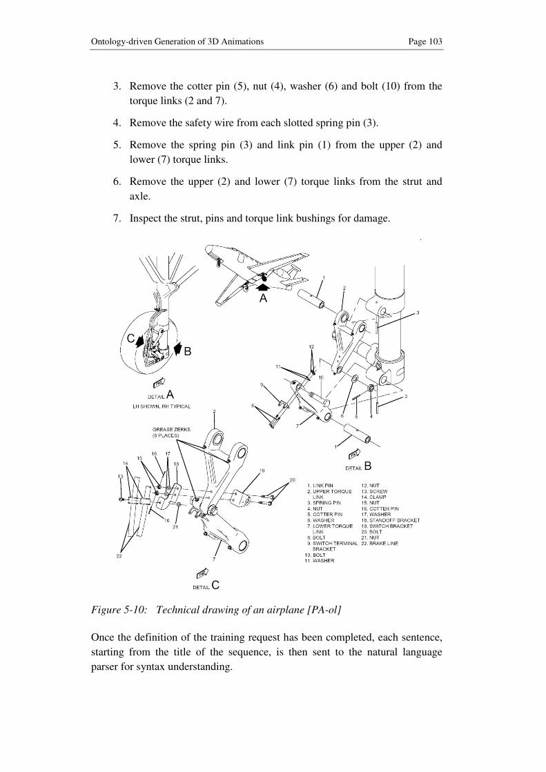
Ontology-driven Generation of 3D Animations Page 103
3. Remove the cotter pin (5), nut (4), washer (6) and bolt (10) from the
torque links (2 and 7).
4. Remove the safety wire from each slotted spring pin (3).
5. Remove the spring pin (3) and link pin (1) from the upper (2) and
lower (7) torque links.
6. Remove the upper (2) and lower (7) torque links from the strut and
axle.
7. Inspect the strut, pins and torque link bushings for damage.
Figure 5-10: Technical drawing of an airplane [PA-ol]
Once the definition of the training request has been completed, each sentence,
starting from the title of the sequence, is then sent to the natural language
parser for syntax understanding.

Page 104 Chapter 5
5.5 Phase 2: Natural Language Parsing
Natural language sentences usually comprehend ambiguous meanings that are
sometimes difficult to be understood by humans. People use their own experi-
ence and common sense to understand the real meaning of a generic sentence.
However, the same task is extremely difficult for a computer, which can match
single words with the ones stored in a database. A word or a verb sharing the
same syntax can also have different meanings: for example, for the linguistic
element “links”, once extracted from the original context, it is impossible,
without additional information, to decide whether it refers to the plural of the
word “link” or the third person of the verb “to link”.
State-of-the-art approaches in natural language parsing, as already shown in
section 4.1.2, exploits probabilistic parsers to interpret sentences, according to
maximum likelihood criteria. Therefore, the use of a probabilistic parser within
the NLP phase enhances the power of the proposed approach, by reducing the
possibility of error in the identification of synonyms. In this way, the parsed
phrase, and in particular elements at a word level, which are subsequently
passed to the ontology for matching, are labeled as the most likely ones. For
the proposed approach, the natural language parser is considered as a black-box
whose input and output are known but the processing is outside the scope of
this book.
The natural language parsing phase has a double purpose:
• on a phrase level, it is necessary to understand the phrase structure by
identifying different kinds of sub-phrases, like a verb phrase, a noun
phrase or a prepositional phrase
• on a word level, it finds out the role covered by each word (noun, de-
terminer, adjective, verb, etc.)
The result of this phase is the retrieval of the sentence in a structured form,
where constituting elements are recognized and labeled, according to the corre-
sponding function covered in the sentence.
5.5.1 Phrase Level
Each sentence contains at least two kinds of elements on a phrase level: a noun
phrase and a verb phrase. Direct questions are not considered since their use in
technical documentation for training purposes are not realistic.
• A verb phrase (VP) is headed by the main verb, thus including the core
information of each sentence; it can also contain a noun phrase, as ob-
ject of the verb.

Ontology-driven Generation of 3D Animations Page 105
• A noun phrase (NP) contains a noun or a pronoun, optionally accom-
panied by some modifiers; it can play the role of the subject or the ob-
ject of the main sentence.
Other phrase levels, which can be present in a sentence, are:
• Prepositional Phrase (PP), composed by a preposition and a comple-
ment (e.g. on the table)
• Adjective Phrase (ADJP), headed by an adjective (e.g. full of liquid)
• Adverb Phrase (ADVP), consisting in a single or multiple adverb
The analysis on a phrase level is needed to subdivide the generic training se-
quence into simpler phrases: as shown in the “ad hoc” sequence, one sentence
can be made up of multiple phrases, including multiple kinds of phrases. Be-
tween them the individuation of prepositional phrases is extremely important:
prepositional phrases add additional information that must be directly con-
nected to the main phrase.
5.5.2 Word Level
The phrase level analysis previously introduced gives an overview of the over-
all sentence through its overall structure but it does not give further information
about the role played by each lexical element within the sub-phrases.
Within the word level analysis, different lexical entities (noun, verb, adjective
or adverb) are identified and labeled by the natural language parser, according
to the role played by each word. A common way to represent natural language
parsing output is the use of a parse tree structure, where the sentence is divided
at first into phrase level and eventually into word level. According to the train-
ing request, defined in the section 5.4.2, a sample parse tree for the first task is
displayed in figure 5-11.
The aim of this phase is to improve the subsequent ontology matching phase by
identifying on a lower level words and relations between them; this allows, for
example, the management of multiple objects corresponding to a single verb,
which would not be possible with just an analysis on a phrase level. In the ex-
ample, screw, clamps and nut are recognized as nouns connected to the verb
“remove”.
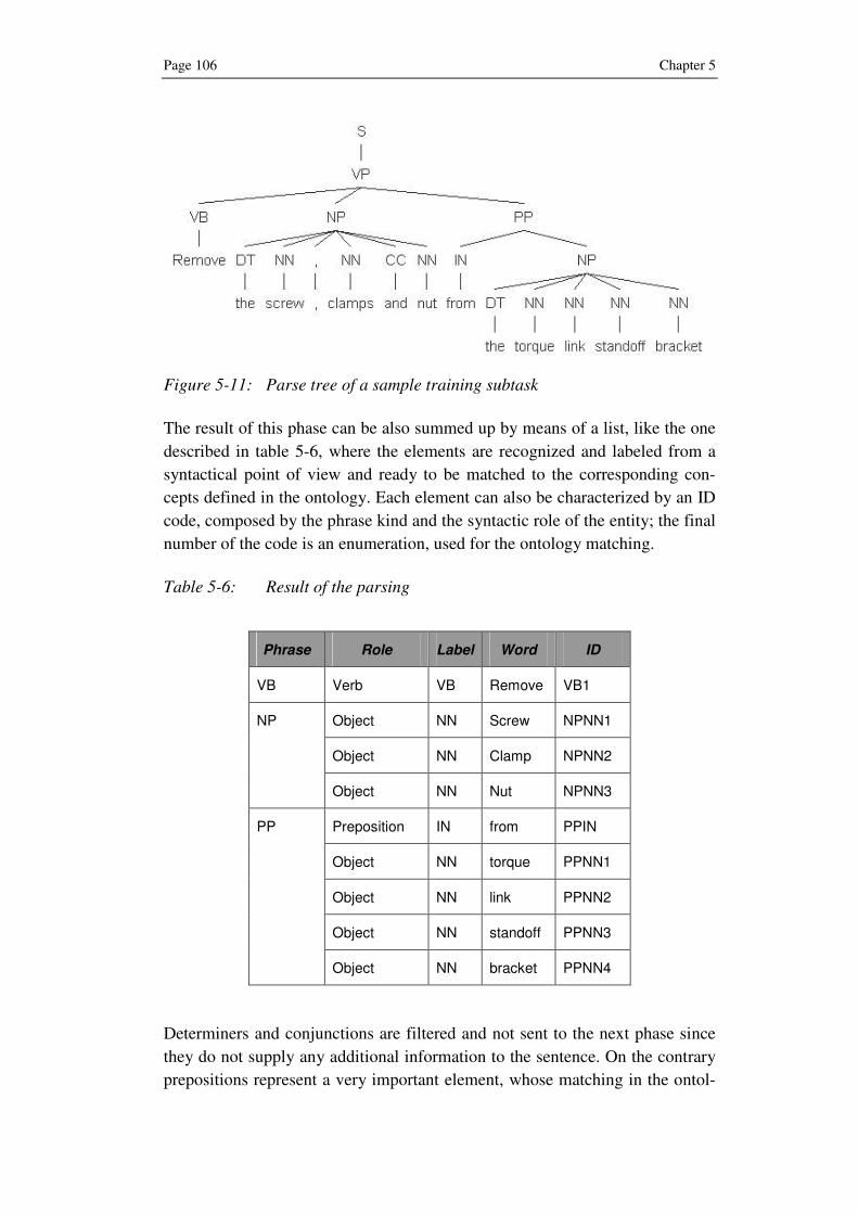
Page 106 Chapter 5
Figure 5-11: Parse tree of a sample training subtask
The result of this phase can be also summed up by means of a list, like the one
described in table 5-6, where the elements are recognized and labeled from a
syntactical point of view and ready to be matched to the corresponding con-
cepts defined in the ontology. Each element can also be characterized by an ID
code, composed by the phrase kind and the syntactic role of the entity; the final
number of the code is an enumeration, used for the ontology matching.
Table 5-6: Result of the parsing
Phrase Role Label Word ID
VB Verb VB Remove VB1
Object NN Screw NPNN1
Object NN Clamp NPNN2
NP
Object NN Nut NPNN3
Preposition IN from PPIN
Object NN torque PPNN1
Object NN link PPNN2
Object NN standoff PPNN3
PP
Object NN bracket PPNN4
Determiners and conjunctions are filtered and not sent to the next phase since
they do not supply any additional information to the sentence. On the contrary
prepositions represent a very important element, whose matching in the ontol-
Ontology-driven Generation of 3D Animations Page 107
ogy is necessary to include additional information, like motion or positioning,
within the training animation
5.6 Phase 3: Ontology Matching
The ontology matching phase follows the natural language parsing and lets
syntactical entities, previously recognized and labeled by the parser, being
matched to concepts defined in the ontology core. According to the structure of
a training sequence, the matching phase can be subdivided into two main parts:
at first, the matching of the topic followed by the matching of each single sub-
task building up the training session.
In order to link the syntactical elements to the ontology concepts, the method
performs the matching of subject, verb, one or multiple objects and eventual
complements. The matching procedures, shown in the following sections, are
to be intended just as a high level description, since the development of a
matching procedure is outside the scope of this book.
The result of the matching phase is a formal description of the training task
characterized by the involved entities, i.e. objects, and the actions performed
on them or through them. This formal description is eventually sent to the
script generator, which translates it into the corresponding scene graph, by add-
ing the geometry of the 3D models and the necessary transformations.
5.6.1 Topic Matching
The first element to be matched is the title of the training sequence because it
implicitly delimits the portion of domain knowledge that is involved in the
training session: the topic contains information about the main action together
with the main concept, whose elements are eventually involved within each
training subtask. Topic matching is therefore extremely important for the
matching of the subsequent subtasks. For example, it would be quite impossi-
ble matching correctly the concept “bolt” in a subtask, without having any ad-
ditional information about the higher concept to whom it refers; in fact, if the
title entered is “changing tire in a car”, the domain is then restricted to the
“car” concept and eventually to the “tire” concept, thus making the identifica-
tion of the involved “bolt” concept easier.
The topic matching is analogous to the subtask matching, which is described in
the next session, since their structure is exactly the same. The difference is rep-
resented by a strategic factor: the matching of the main concept, and of its main
instance if specified, contained in the topic not only individuates the eventually
involved sub-parts but it allows identifying the 3D model for its use in the ani-

Page 108 Chapter 5
mation. Therefore, it constitutes the first step for the model mapping described
in section 5-7.
Once the title of the training sequence has been matched with the correspond-
ing concepts, each sentence of the training session, i.e. each subtask, is sequen-
tially matched with the elements defined in the domain ontology.
5.6.2 Subtask Matching
The subtask matching process as well as the topic matching follows the usual
sequence of the triple: subject, verb, and object. At first the subject or the end
user role if present, is matched; then the verb, followed by the corresponding
one or multiple objects, complete the matching of a generic sentence.
5.6.2.1 Subject
The first entity to be processed, following the structure of a normal phrase, is
the subject. It can represent the user role, in case of a human performing the
action, or the main object, in case of technical parts.
Training sentences usually refer to a generic user by means of the imperative
form, thus letting subject implied. In this case the procedure is able to deduct
from the context defined by the verb and the related objects, the corresponding
role that constitutes the actor of the training sentence. This result is achieved
exploiting relations defined in the action ontology: each verb is in fact charac-
terized by the “hasDomain” relation, which specifies the role performing the
action.
If the subject of the action is represented by a technical part, the matching pro-
cedure is analogous to the one regarding an object and is described in section
5.6.2.3.
5.6.2.2 Verb
While the subject of a sentence can be implied, the verb represents the core
element of a sentence and cannot be implied. However, the verb alone cannot
give enough information about the action, unless the related objects are speci-
fied; for this reason the matching of the verb is strictly connected to the one
regarding objects.
The matching phase for the verb is achieved through the combined use of:
• Syntax matching
• “KindOf” relation
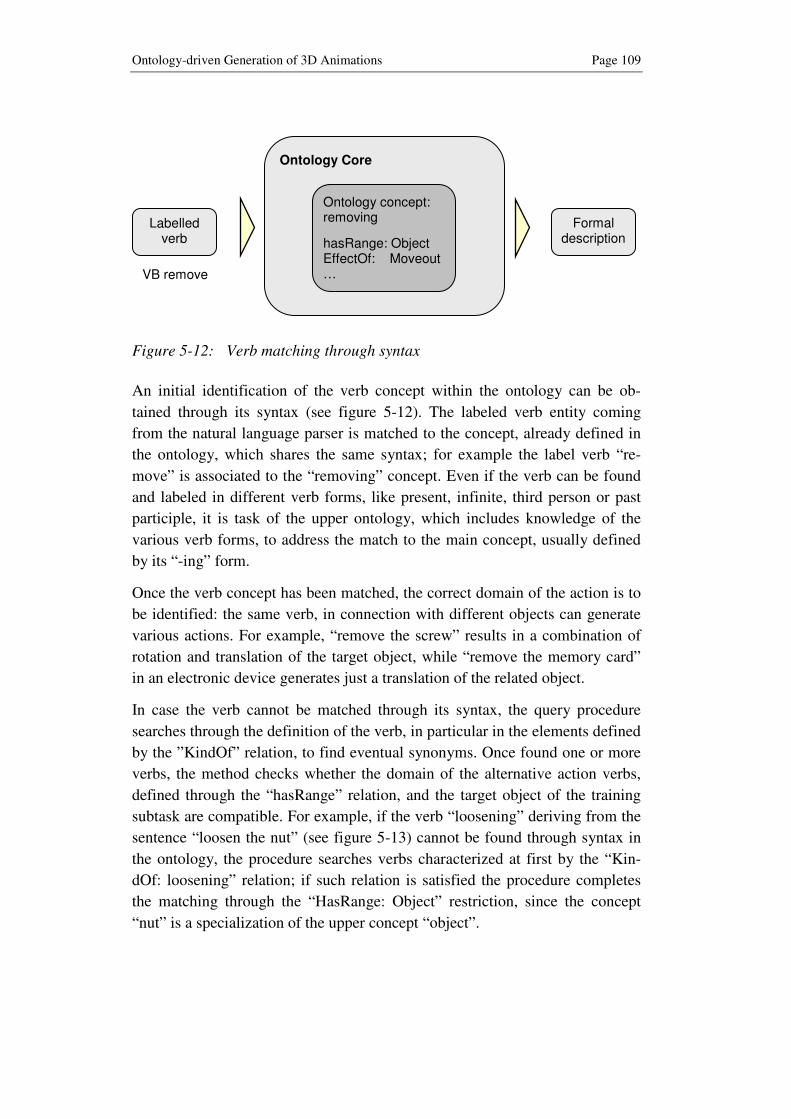
Ontology-driven Generation of 3D Animations Page 109
Figure 5-12: Verb matching through syntax
An initial identification of the verb concept within the ontology can be ob-
tained through its syntax (see figure 5-12). The labeled verb entity coming
from the natural language parser is matched to the concept, already defined in
the ontology, which shares the same syntax; for example the label verb “re-
move” is associated to the “removing” concept. Even if the verb can be found
and labeled in different verb forms, like present, infinite, third person or past
participle, it is task of the upper ontology, which includes knowledge of the
various verb forms, to address the match to the main concept, usually defined
by its “-ing” form.
Once the verb concept has been matched, the correct domain of the action is to
be identified: the same verb, in connection with different objects can generate
various actions. For example, “remove the screw” results in a combination of
rotation and translation of the target object, while “remove the memory card”
in an electronic device generates just a translation of the related object.
In case the verb cannot be matched through its syntax, the query procedure
searches through the definition of the verb, in particular in the elements defined
by the ”KindOf” relation, to find eventual synonyms. Once found one or more
verbs, the method checks whether the domain of the alternative action verbs,
defined through the “hasRange” relation, and the target object of the training
subtask are compatible. For example, if the verb “loosening” deriving from the
sentence “loosen the nut” (see figure 5-13) cannot be found through syntax in
the ontology, the procedure searches verbs characterized at first by the “Kin-
dOf: loosening” relation; if such relation is satisfied the procedure completes
the matching through the “HasRange: Object” restriction, since the concept
“nut” is a specialization of the upper concept “object”.
Ontology Core
VB remove
Ontology concept: removing
hasRange: Object EffectOf: Moveout …
Labelled verb
Formal description

Page 110 Chapter 5
Figure 5-13: Verb matching through alternative concepts
Strictly connected to the verb matching is the management of spatial preposi-
tions, which represent a critical element within the proposed approach and, in
general, for natural language processing. One of the most important contribu-
tions in the research area [Her86] states that the topic is too complex to be suc-
cessfully arranged into general rules; just very simple cases can be treated and
once a general rule arises, an exception can be found. Spatial prepositions
build, in fact, a bridge between natural language and the spatial location of the
considered elements; moreover, in a text-to-scene approach like the proposed
one, they pave the way to the representation of the elements in the virtual
scene.
Prepositions can be identified essentially in two ways: on the one hand, in case
of verbs that explicitly need a preposition, like “check through” or “look for”,
they can be included in the action ontology as part of the verb itself. On the
other hand, their matching becomes more complex and requires a deep under-
standing of locative expressions, defined at first in the upper ontology and then
enriched of eventual specific cases within the domain ontology, as shown in
section 5.2.2.4.
5.6.2.3 Object
Matching an object in the ontology is a quite complex process because of the
multiplicity of tasks, domains and situations where a single object can be in-
volved into. This problem can be well represented, for example, by fasteners,
like screws or bolts, which can theoretically be present in every object and
available in a multiplicity of kinds.
Ontology Core
No ontology concept found
VB loosen +
NN Nut
Labelled verb
Alternative concept
loosening
Ontology concept
unscrewing
KindOf: loosening
hasRange: Nut
…
Formal description

Ontology-driven Generation of 3D Animations Page 111
Nouns coming from the natural language parsing phase are searched in the up-
per ontology and, whether the concept is not found, in the part ontology for the
identification of the involved elements.
It is necessary to differentiate two main cases, according to where the noun
representing the object is contained:
• Training sequence title
• Single training sentence
The noun, describing an object in the training sequence title, has its main func-
tion in delimiting the knowledge domain. It usually defines a higher level con-
cept, which includes various sub-elements in its hierarchy; therefore, once the
object is matched, also all connected concepts, together with their instances,
must be considered for their likely use in the content of the training request. As
introduced before in the car domain, the “Porsche 911” is the concept but it is
not a standalone one: it is composed by a myriad of parts from the smallest
screws and bolts up to the chassis.
On the other hand, nouns included in each training subtask represent stand-
alone elements, which are to be linked to their models or to specific parts
within the main 3D model; an example could be represented by the tire of the
car to be removed. Therefore, in this case, the matching procedure ignores
eventual sub-elements in the hierarchy but keep connections with upper con-
cepts, to which the nouns may refer (tire-axis).
Figure 5-14: Matching of the “Drill Bit” concept in an extract of the Part
Ontology
locatedIn
connectedTo
isA
isA
Drill Bit
Mechanical Part
Drill Chuck
Tool
…

Page 112 Chapter 5
The matching of the object is performed through an ontology query, according
to the lexical elements that have been identified by the natural language parser.
The result is not only the matching of the single concept but also the retrieval
of all the concepts linked to it by a relation: it would be a non-sense, identify-
ing the “drill bit” (see figure 5-14), for example, without referring to its upper
level concept, e.g. the “drill chuck”, which needs to be represented as well in
the final training animation.
Particular attention must be given to compound nouns: they represent noun
phrases, which are made up of a noun preceded by a modifier, like “parking
brake” or “milling machine”. In this case the procedure considers, within the
same noun phrase that includes the compound noun, the two adjacent elements
as one word. The approach is able to manage compound nouns that are com-
posed by a maximum of four nouns; this is achieved by linking all the elements
for a three element compound noun (e.g. “landing gear brake”) or to the linking
of two couples of elements (e.g. “torque link”) and (“standoff bracket”), for a
four word compound noun.
5.6.2.4 Adjectives and Adverbs
Adjectives and adverbs can be present in a generic training sentence, where
they supply additional information about the elements and the environmental
conditions. A particular role is played by adjectives, since they enrich elements
defined by nouns through various attributes.
A first distinction, which is also used for the matching procedure, regards ad-
jectives and past participles that can play a similar role adding more informa-
tion to the noun they refer to.
This preliminary step is necessary to define the section of the ontology core
used for matching of adjectives: in fact, past participles derive from the corre-
sponding verbs, whose definition is stored in the action ontology, while adjec-
tives can be managed through attributes or relations in the upper ontology as
well as in the domain ontology whether domain specific.
Past participles, e.g. “closed” or “connected”, are considered as verbs and
matched by the “-ing” form concepts, like “closing” and “connecting”, defined
in the action ontology, if not already in the upper ontology. While their match-
ing can be provided referring to the original verbs, their representation in the
training animation remains anyway very problematic: they refer to actions that
have already been done: for example, a part is “connected” if the connection
has already taken place, therefore the action described by the adjective does not
suit the creation of an animation, which displays tasks as a continuous flow,
since it has been already been concluded.

Ontology-driven Generation of 3D Animations Page 113
The same difficulties can be found also regarding adjectives: while some “tan-
gible” adjectives, regarding color, shape and material, can be managed and
therefore matched through attributes or relations in the ontology, the matching
and the subsequent representation of abstract adjectives remains too complex
for an automatic procedure. It is in fact not possible for a computer establish
what is far, small, slow or different, within a single natural language phrase.
Also adverbs are affected by the same problem: the majority of them expresses
some abstract properties, like “by hand”, “carefully” or “properly”, which theo-
retically can be matched in the ontology but that are quite impossible to be
visualized in the animation. The solution can be represented in this case by the
use of different metaphors rather than the pure visualization of the action.
5.6.3 Formal Description of the Animation
The result of the matching phase is represented by a formal description of the
overall training session, in terms of objects to be represented in the virtual
scene and of the basic transformations commands, deriving from the action
ontology. The formal description is composed by the two components:
• world description
• task description
The world description contains the elements building the virtual scene, still on
a conceptual level since the 3D models and their geometry retrieval is achieved
during the following model mapping phase. Such elements have been directly
identified by the ontology matching, together with the necessary related con-
cepts, which are included in the training sentence or inferred by the context.
The task description contains information about the actions involving the ele-
ments contained in the world description. The verbs matched by the ontology,
together with additional information regarding objects or tools used for the
task, complete the formal description of the animation. Verbs are subdivided
according to the motion effect they cause into the five main categories already
defined in the action ontology:
• Movein and moveout, in case of motion respectively approaching or
leaving the object;
• Be, in case of static positioning;
• Rotate, in case of rotations;
• Scale in case of change of dimensions of an object, used also in zoom-
ing in and out.

Page 114 Chapter 5
For example, the animation atom “removing a drill bit” is characterized by a
formal description containing the following parameters:
• KindOf: loosening, taking, taking away
• HasDomain: Maintenance
• HasRange: Object (to be determined by the following step)
• EffectOf: Moveout length_object
• Duration (according to the target object)
The formal description is eventually used by the script generator for building
the scene graph of the animation.
5.7 Phase 4: Model Mapping
Current state-of-the-art 3D modeling makes use of CAD tools coupled to PDM
systems, which have been introduced in chapter 2.
Within this phase, each matched concept in the part ontology is linked to its
corresponding 3D model, stored in the model repository or in a PDM System
(see figure 5-15), through a series of interfaces. It is reasonable thinking that
each part defined in the 3D model is characterized by an ID code, which can be
associated to the corresponding part defined in the part ontology, thus enabling
a feasible information exchange between the two systems.
Figure 5-15: Screenshot of a PDM system

Ontology-driven Generation of 3D Animations Page 115
The first step of the model mapping phase is the identification of the main con-
cept, i.e. the matched object contained in the training topic, in the 3D model
database. For this task, the identification is possible searching through meta-
data in the model repository or in the PDM system the main instance. In case
an automatic identification cannot be possible, the possibility to manually enter
the main 3D model is provided to the user.
Once identified the main concept, the corresponding 3D model is recalled, in
order to get its geometry; also sub-parts, contained in or connected to the main
concept, are recalled, together with their positioning.
The model mapping phase has also the aim of choosing the correct level of
detail of the model according to the end user role, target of the training session.
Three different levels of detail are foreseen for the roles defined in the ontol-
ogy core:
• low detail, showing the 3D model where just the more external layers
are visible
• middle detail, including internal layers but not the detail of the smallest
components.
• high detail, where all layers of the 3D model are visible
At the end of the mapping phase, before the animation script is created, the
method provides the end user with the possibility to give some feedback re-
garding the individuation of the correct elements in the 3D repository. The
automatic identification of 3D models according to natural language instruc-
tions can in fact generate results, which are not the desired ones. In this case
the end user can refine the natural language instruction in order to achieve a
better match in the ontology and subsequently in the model mapping.
5.8 Phase 5: Animation Script Generating
Once the 3D models corresponding to the parts involved in the animation have
been identified by the previous phase, the last necessary step is the translation
of the formal description into the final animation script, which includes move-
ments, like translations and rotations, of the elements in the virtual scene.
The animation script is created by the script generator, a software agent that
translates the formal description of the animation into a graphics file format
script. The script generator collects all the necessary information in a standard
template, which eventually builds up the scene graph for the requested anima-
tion. This is achieved by mapping action descriptions contained in the formal
description to specific commands of the scene graph data structure.

Page 116 Chapter 5
The main elements of the scene graph, and therefore of the standard template,
can be summed up in the following general nodes:
• Geometry data contains information about the geometry of parts to be
visualized in the virtual scene (dimension of the objects, colors, shading
parameters, etc.)
• Group constitutes a virtual assembly of the elements
• Transformation collects modifications of the scene in terms of transla-
tions, rotations and scaling
The software agent is also responsible of the time management: to every ac-
tion verb are coupled within the ontology predefined values for time and speed
of the task to be performed. For example, the combination of the concepts “re-
moving” and “screw” is associated a predefined total time for the action, e.g.
1.5 seconds, as well as the speed values for the translation and of the rotation.
Another important part of the script generator is played by the virtual camera
management, including camera point of view and speed. The virtual camera
represents the point of view of the end user and must be therefore carefully
considered. The camera must focus on the target of the training for a time nec-
essary to the user to locate it and must also move not so fast, in order to let the
operations understandable.
The management of the virtual camera allows also the delivery of different
views according to the role target of the training session. For roles requiring a
high level of detail the virtual camera must be positioned very close to the vir-
tual object, in order to appreciate the smallest details. On the contrary for roles
requiring a more general view, the camera can be positioned at a longer dis-
tance.
Once the animation script has been created by the script generator, the anima-
tion can be visualized through the corresponding viewer. In order to allow a
feedback about the animation parameters, the method lets the user specify a
final feedback about timing of the animation as well as positioning and speed
of the virtual camera. In this way the script of the animation can be adapted to
the user request and the process can be therefore continuously improved.

Prototype Implementation and Validation Page 117
6 Prototype Implementation and Validation
The proposed research approach represents an innovative way to create 3D
animations for training purposes, combining state-of-the-art natural language
understanding, knowledge-based services, by means of an ontology, and 3D
animation authoring techniques.
In order to evaluate the feasibility and the efficacy of the overall approach, a
prototype implementation has been realized and validated. This section de-
scribes the realization of the proposed method starting from the definition of
the ontology core and then analyzing each single step of the process model.
The whole research approach has been inspired by the European Project Ko-
BaS (Knowledge Based Customized Services for Traditional Manufacturing
Sectors Provided by a Network of HighTech SMEs), whose aim is to supply
modern manufacturing machines with knowledge-based software solutions,
from 3D simulation and training, to part-program creation, and FEM analysis
among the most important components (see figure 6-1). The project, where the
author has been involved into, has been completed in June 2007 after a three-
year work period. Even if the proposed research approach is not part of the
KoBaS project itself, the experience acquired in the manufacturing machine
domain has led to use of a mechanical device as demo case.
Figure 6-1: KoBaS knowledge based services
The chosen device is a standard Drill Press, actually available on the market; in
order to test and validate the proposed approach in real conditions, the consid-
ered training sequences have been extracted from a real operations and mainte-
nance manual.

Page 118 Chapter 6
The followed implementation strategy starts with the choice of the existing
upper ontology and the analysis of the mechanical domain coverage; the devel-
opment of the part and action ontologies completes the definition of the ontol-
ogy core. Then, the developed process model is applied and the feasibility of
the process is evaluated.
6.1 Ontology Choice and further Development
The ontology core constitutes the most important part of the proposed ap-
proach; its definition represents a preliminary step of the method. This section
describes at first the choice of an existing upper ontology, in order to have a
shared and domain-independent knowledge base and at the same time a com-
mon framework; this function is then exploited for the development of the nec-
essary domain ontologies that supply the domain knowledge of technical parts
and of the actions performed on them or through them.
6.1.1 Upper Ontology
Some of the most important existing upper ontologies have already been exam-
ined in section 4.2.1.1; among them two candidates have been selected for their
completeness of content, the SUMO and the Cyc ontologies. Dealing in fact
with natural language, where a single sentence can contain various concepts
from different domains, the upper ontology must embed a wide and intercon-
nected knowledge.
The two ontologies have been evaluated according to a number of parameters,
which can be summed up as follows:
• number of concepts contained
• lexical mapping
• richness of instances
Both candidates represent two complete upper ontologies, from a knowledge
point of view: SUMO contains thousand concepts and approximately 4000
assertions including over 800 rules while ResearchCyc includes more than
300.000 concepts and 3.000.000 assertions, using more than 25.000 relations.
Also from a lexical point of view, both ontologies have a wide knowledge
since they both map the whole Wordnet.
The key factor, which has influenced the final decision, is represented by the
absence of instances in SUMO, which is structured in a network of subclasses,
being thought as a framework for the further development of multiple domain
ontologies. On the other hand, Cyc is able to characterize, even if in different
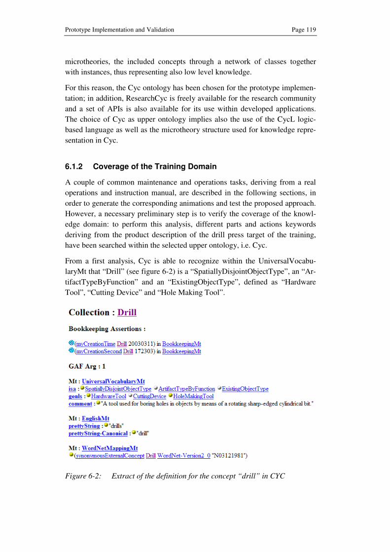
Prototype Implementation and Validation Page 119
microtheories, the included concepts through a network of classes together
with instances, thus representing also low level knowledge.
For this reason, the Cyc ontology has been chosen for the prototype implemen-
tation; in addition, ResearchCyc is freely available for the research community
and a set of APIs is also available for its use within developed applications.
The choice of Cyc as upper ontology implies also the use of the CycL logic-
based language as well as the microtheory structure used for knowledge repre-
sentation in Cyc.
6.1.2 Coverage of the Training Domain
A couple of common maintenance and operations tasks, deriving from a real
operations and instruction manual, are described in the following sections, in
order to generate the corresponding animations and test the proposed approach.
However, a necessary preliminary step is to verify the coverage of the knowl-
edge domain: to perform this analysis, different parts and actions keywords
deriving from the product description of the drill press target of the training,
have been searched within the selected upper ontology, i.e. Cyc.
From a first analysis, Cyc is able to recognize within the UniversalVocabu-
laryMt that “Drill” (see figure 6-2) is a “SpatiallyDisjointObjectType”, an “Ar-
tifactTypeByFunction” and an “ExistingObjectType”, defined as “Hardware
Tool”, “Cutting Device” and “Hole Making Tool”.
Figure 6-2: Extract of the definition for the concept “drill” in CYC

Page 120 Chapter 6
Also the concepts of elements building the drill can be identified, even if with
some differences: more common concepts, like “fastener”, “lubricant” or
“wire” are found easily while more specific ones, like “controller” or “spin-
dle”, as expected, are not enough detailed and do not allow an exhaustive de-
scription of the parts.
According to the structure of Cyc, a disadvantage is that concepts can be found
in different microtheories: the most important and general microtheory is the
UniversalVocabularyMt, which as the name suggests acts like a dictionary,
while closely related to the desired structure seem to be the ProductGMt, which
includes concepts about formal products, and the ProductPhysicalCharacteris-
ticsMt, which includes knowledge of the physical characteristics of products.
Concerning possible action verbs that can be found in a generic training se-
quence for the target domain, Cyc is able to match, even if with more than one
meaning, common verbs like “loosening”, “checking”, “turning”, “inserting” or
“removing”, in the UniversalVocabularyMt, HumanActivitiesMt and Product-
UsageMt microtheories. It has been not possible, however, a correct matching
of the verb “threading”.
An interesting Cyc feature is the possibility to express concepts in function of
other concepts: for example, the verb “screwing” can be defined as function of
the concept “screwdriver”, which is used for screwing. This feature can be ex-
ploited in the development of the domain ontology, where analogous functional
relations “UsedFor” and “CapableOfReceivingAction” ideally link an object
with the conceptually related actions.
Concluding the analysis of the coverage, it can be stated that knowledge stored
in Cyc constitutes a good starting point for the individuation of concepts re-
garding objects and actions. However, its structure is not really an ontology,
since concepts are characterized just by hyponymy relations. Cyc is rather a
huge knowledge-base, whose upper part is an ontology. There is therefore a
need to further specify the necessary concepts by developing a domain ontol-
ogy.
6.1.3 Domain Ontology
Even if Cyc as upper Ontology already embeds a wide domain independent
knowledge, additional domain knowledge including also an exhaustive set of
relations is needed. The target world to be described by the developed domain
ontology is represented by a mechanical device, in the considered case a Drill
Press.
Prototype Implementation and Validation Page 121
This section briefly introduces a first development of the domain ontology, into
its two components, part ontology and action ontology; further development
work is still however going on.
6.1.3.1 Part Ontology
The developed part ontology constitutes a first modeling of the target world
through the concepts that represent its constituents. Top-down and bottom-up
approaches have been followed, even if for different kinds of concepts. At first
through the top-down approach, the drill press main concept has been further
developed by the classes:
• Mechanical part: a movable part, which is involved in the production
process
• Electrical part
• Structural part: a static or movable part, which builds up the structure of
the overall machine, without taking part in the production process
• Functional part: a non-mechanical part, which supports the functioning
of the machine
• Fluid, e.g. Lubricant
The defined classes have been further specified by additional subclasses, like
the concepts “tool”, “spindle” and “feed handle” for the class “mechanical
part” or the concepts “cable”, “motor” and “power supply” for the “electrical
part” class.
The “structural part” class contains the subclasses “base”, “column” and
“case”, which together builds up the structure of a generic drill press. Addi-
tional functional parts that are however needed for the functioning of the ma-
chine are represented by the “controller”, “display” and “pipe” concepts. The
class “fluid” is further specified by the lubricant concept, which can be essen-
tially of two kinds “oil” or “grease”.
The bottom-up approach has been followed on the other hand to start from
lower level concepts and their instances and to connect the resulting class to
the corresponding upper class: for example the concepts “screw” and “joint”,
together with their instances representing the different kinds of screws and
joints, have been arranged into the “fastener” subclass of the more general
“structural part”. Very important in this case is the elimination of every unar-
ranged concept, which lead to inconsistence and to a wrong modeling of the
domain ontology; the conceptualization of the target domain must be com-

Page 122 Chapter 6
pletely exhaustive. Due to the simple test case, the use of the mixed approach
has not been necessary.
Table 6-1: An extract of the drill press domain ontology
Concept IsA Conceptually-
RelatedTo ConnectedTo AllowedMovement
Tool Hole; Wear ; Bit Spindle Movein/Moveout
Rotation
Spindle Speed, Rotation Motor Rotation axis z
Feed handle
Mechanical part
Tool, Position, Lever
Case Rotation axis z
Cable Electricity Power Supply -
Motor Power, Power Supply Movein/Moveout
Power Supply
Electrical part
Sped Motor; Cable -
Base Ground Column -
Column Structure Base, Case -
Case Cover, Protection
Column, Motor Movein/Moveout
Fastener
Structural part
Screwdriver, Joint, Tool, An-chor, Hole
Base, Case, Column
Movein/Moveout
Rotation axis z
Display Parameter, Setting
Case -
Pipe
Functional part
Fluid Motor -
Oil Lubricant Drop, Fluid Pipe -
Instances of the concepts mentioned above have been linked through a path to
the corresponding 3D models, in order to allow the retrieval of the geometry
during the phases of the proposed method.
6.1.3.2 Action Ontology
Differently from the part ontology, where the target domain is fixed, the action
ontology includes concepts of verbs covering a wide domain that deal with the

Prototype Implementation and Validation Page 123
mechanical device, from operations to assembly or maintenance sessions. The
spectrum of verbs that can be found in a training session is therefore huge.
However, the general knowledge of the upper ontology in some way simplifies
the development of the action ontology: verbs are in fact mostly derived from
the upper ontology and enriched with knowledge of the transformation itself,
also in connection with the target objects.
Among the classes of verbs included in the action ontology, already introduced
in chapter 5, just the physical verbs have been implemented in the prototype.
With the exception of verbs defining positions that can be linked to the “be”
command, the definition of abstract verbs is left to the upper ontology since
they do not contribute a visual representation in the 3D animation.
For the implementation phase greater attention has been given to the physical
“action on object” verb class (see table 6-2). Each verb has been described
through a set of relations: the antonym concept of the verb, the role domain of
the action, the range of connected objects and the respective effects of the ac-
tion allow a specific characterization of every concept.
Table 6-2: An extract of the defined “action on object” verbs
Concept hasContrary hasRange hasDomain EffectOf
Open Close Case Operation Maintenance
Rotate door y-axis
Screw Maintenance Rotate screw z-axis,
Moveout y-axis
Structural_ part
Maintenance Moveout box z-axis
Remove Place, Put
Mechanical_ part
Maintenance Assembly
Moveout spindle z-axis
Loosen Tighten Fastener: Screw
Maintenance Assembly
Rotate screw z-axis
Change - Mechanical_ part
Maintenance Moveout spindle z-axis
Fade out, Fade in
Movein spindle z-axis
Use Ignore Functional_ part
Operation Rotate handle x-axis
The concepts included in the part ontology have also been characterized
through the hasDomain relation and directly connected to the corresponding
Page 124 Chapter 6
roles. The effect of each verb described in the table is strictly dependent on the
geometry of the related objects, thus the described axes are to be considered
just as an indication.
In a first development phase it is not foreseen the implementation of the “ac-
tion with tool” verbs, where the introduction of the external models is neces-
sary in order to represent the tools necessary to complete the action. At the
same time, “pure action” verbs, which even if present in the training session
play a marginal role, are not included in the developed action ontology.
6.1.4 Roles
The simplicity of the selected test device implies that in the specific case roles
play a marginal role; the drill press CAD model presents in fact just in the main
unit the possibility to place specific object on layers. That is the reason why the
in the implementation just two roles have been managed:
• Operation/sales, which requires the full 3D model in order to have an
overall view of the target device
• Assembly/maintenance, which gives more detail of the main unit, set-
ting external structural parts, like the main unit case, invisible.
6.2 Implementation of the Process Method
The developed part and action ontologies, completed by the Cyc upper ontol-
ogy, represent the core of the process method proposed in this research ap-
proach. This section describes the implementation of the process model, al-
ready introduced in chapter 5, through the sequence of phases that build it up.
The developed system is made up of a main application, which includes the
natural language parser, the ontology core and the script generator; the applica-
tion is also connected through an interface to the 3D model repository.
An integrated viewer is also provided in order to allow visual feedback in the
identification of the correct 3D objects within a more complex model, as well
as during the visualization of the resulting animation
The implementation of every phase building the process model, starting from
the training request and ending with the generation of the animation script, is
analyzed in the following sections.

Prototype Implementation and Validation Page 125
6.2.1 Training Request
Product documentation provided by manufacturers includes detailed informa-
tion about the product, like system operation, safety and maintenance instruc-
tions. Such information constitutes the starting point for the implementation
and at the same time a good test for the feasibility of the proposed method.
For implementation and validation purposes, a couple of installation and opera-
tions procedures, extracted from a real drill press (see figure 6-3) instruction
manual, are considered.
1. Motor Unit
2. Top Cover
3. Cover Lock
4. Feed Handle
5. Drill Chuck
6. Power Switch
7. Base
8. Parallel Guide
9. Column
10. Lock Screw
11. Wrench Hole
12. Anchor Holes
13. Depth Gauge Knob
14. Column Adjuster Screw
Figure 6-3: Extract from the instruction manual [MM-ol]
To test the feasibility in different conditions, two procedures differing in their
structure, have been chosen: a first procedure regarding the assembly of the
Drill Press is characterized by a numbered sequence of subtasks. The numbers
included in every sentence refer to the parts displayed in figure 6-3.
Procedure 1: Assembly of the Drill Press 81631
1. Anchoring of the unit is possible using two screws (not provided)
through anchor holes 12.
2. Loosen the lock screw 10 by turning counterclockwise and slide the
motor unit 1 towards the top of the column 9; tighten the lock screw to
hold the motor unit in position. If applicable, remove protective cap
from spindle threads.
3. Install the drill chuck 5 by threading it onto the bottom of the spindle;
insert the wrench into the hole 11 in the spindle to keep the spindle
from turning while you tighten the chuck.

Page 126 Chapter 6
4. Thread the feed handle 4 into the spindle feed lever.
A second training procedure regards the installation of drill bits for operations
and is in form of a paragraph that includes has no numbering.
Procedure 2: Installing Drill Bits for Operations
“Using the chuck key, open the chuck just far enough so that the drill
bit can be inserted centrally into the chuck jaws. Carefully tighten the
chuck so that it grips the drill bit on the blank portion of the drill shank.
Do not tighten the jaws on the drill flutes. Remove the chuck key. Ro-
tate the chuck by hand to confirm that the drill bit is inserted properly
and there is no drill wobble.”
The considered training sentences are expressed as usual in imperative form,
being the subject, i.e. the role, implicitly defined by the title itself (“assembly”
and “operations”; this reduces the parsing and the matching phases in the indi-
viduation of the action to be performed together with the target objects.
6.2.2 Natural Language Parser
A natural language parser is a program that is able to supply for a natural lan-
guage sentence, written in English in the considered case, a grammatical analy-
sis, identifying and labeling the single constituents, like subject, verb or object.
The role played by the parser in this phase is to have a first idea of the structure
of each sentence and of the single elements that build it up.
The natural language parser used for this phase is the Lexical Parser, developed
at the Natural Language Processing Group of the Stanford University: it is a
Java implementation of probabilistic natural language parsers, probabilistic
context-free grammar (PCFG) and dependency parsers, and a lexicalized PCFG
parser. The parser is licensed under the GNU GPL and its source is included in
the package, which includes components for command-line invocation, a Java
parsing GUI, and a Java API.
The input text can be entered directly in the parser graphical user interface or
by loading a text file. The two test training procedures have been analyzed by
means of the Stanford PCFG Parser, which automatically subdivides text in-
puts in smaller sentences, ended with a point. Thus, there is no difference be-
tween the two procedure styles; the only difficulty is that for in the first proce-
dure, numbering is recognized as a sentence composed by just a number fol-
lowed by a point. In addition, numbers identifying parts of the device in the
picture, like the one contained in the example procedures, are difficult to be
filtered; the risk is to cause filtering of important details, like the code identify-
ing the kind of a screw or the model number of a generic instance.

Prototype Implementation and Validation Page 127
The parser has some problems with the identification of case sensitive words:
the same word, i.e. the verb “remove”, is recognized as a verb but when the
first letter is written in capital letters it is labeled as adverb. This represents a
serious problem since training subtasks usually start in capital letters.
The output resulting from the probabilistic approach mentioned above is a text
file, containing a parse structure with Penn-Treebank notation, which can also
be visualized through graphical trees. The elements resulting from the parsing
are labeled according to their kind and made available for the ontology match-
ing; this interface is managed through the parser API, which connects directly
with the main application. The following description represents the first sen-
tence of Procedure 2.
(ROOT
(S
(VP
(VP (VBG Using)
(S
(NP (DT the) (NN chuck) (NN key)
(, ,)
(VP
(VP (VB open)
(NP (DET the) (NN chuck)
(ADVP
(ADVP
(ADVP (RB just) (RB far))
(RB enough)
(RB so))
(SBAR
(IN that)
(S
(NP (DET the) (NN drill) (NN bit)
(VP (MD can)
(VP (VB be)
(VP (VBN inserted)
(S
(ADJP (RB centrally)
(PP
(IN into)
(NP (DET the) (NN chuck) (NNS jaws))))))))))))))
6.2.3 Ontology Matching
The ontology matching consists in the identification of concepts that have been
recognized and labeled by the natural language parser. This process is managed
by the main application and regards action verbs as well as the corresponding
objects. The whole phase can be subdivided into a sequential matching through
upper and domain ontology.
In the upper ontology matching, each element is searched by the main applica-
tion through the Cyc API, within Cyc’s UniversalVocabularyMt. This mi-
crotheory, which is the largest one, is the main entrance for the identification of
the concepts; it acts like a dictionary and contains basic information necessary

Page 128 Chapter 6
for the identification of the single elements, which are however not character-
ized through parameters or relations.
Analogously to a dictionary, more senses can be coupled to a single word; a
first possibility to filtering such results is given by the natural parsing labeling
phase. An element labeled as a verb (VB), automatically excludes from match-
ing, a synonym noun or adverb: the word “links”, for example, whether labeled
as a third person verb (VBZ), excludes the plural of the word “link” from the
matching results and therefore refer just to the “linking” concept.
Once an element, i.e. verb or word, is identified in the UniversalVocabularyMt,
the possible meanings are searched in the connected more specific microtheo-
ries:
• HumanActivitiesMt and ProductUsageMt, for verbs.
• ProductGMt and ProductPhysicalCharacteristicsMt, for objects
This first matching step within the upper ontology performs a restriction of the
knowledge domain to the training and mechanical devices sub-domains; at the
same time, it paves the way for the identification of target objects and action
verbs, which are not specified in the more general microtheories and are stored
in the more specific part and action ontologies. The final matching is per-
formed in fact through the domain ontology defined in section 6.1.2, which is
connected to the microtheories mentioned above, in order to give a final char-
acterization of the concepts.
Objects defined in the domain ontology are characterized by a more complex
structure than the one defined in the upper ontology: they include a hierarchy
of concepts, rather than just upper and lower level concepts, and by a series of
relations. Such description of the object is needed for the individuation of parts
or features to be shown in the final animation. In test procedure 1, being the
“drill chuck” connected to the “spindle” through the connectedTo and locate-
dIn relations, the individuation of the former concept and its inclusion in the
3D animation implies also the inclusion of the conceptually related concept of
the latter: both concepts are however not related each other by hyponymy or
hyperonomy relations but are included in the hierarchy of the “drill press” con-
cept.
While the aim of matching words is to individuate objects involved in the train-
ing requests and consequently in the 3D scene, matching of action verbs im-
plies the “translation” of action verbs into a series of transformations of the
objects mentioned before. After the first disambiguation through the mi-
crotheories mentioned above, one or more matched verbs are refined through
the domain ontology. Considering the object related to the action verb, through

Prototype Implementation and Validation Page 129
the “hasRange” relation, not only a correct matching is possible, but also a va-
riety of different animations with the same verb are possible.
Among the considered verbs, a particular case for English is also represented
by the verb “to do”; it can be in fact associated to “making” but it is also used
for negative sentences, e.g. “do not open”. In the latter case the main role is
played by the second verb, which becomes the relevant one for the overall
meaning. For this reason the verb “to do” has not been implemented because a
metaphor to express negatives is still needed.
Within the proposed approach abstract verbs are just used to influence the
management of the virtual camera; in a further development of the approach
they can be managed by textual or visual information to be added to the 3D
animation.
The result of the matching is a formal text description of the animation (see
figure 6-4), a text file containing a higher level description of the animation
scene environment, including the objects involved and their actions, specified
on a higher level language [Bro05]. Also a first preliminary value of the speed
of the movement is indicated. This information is later on managed by the
script generator, which associates the semantic elements to the corresponding
3D models and translates high-level tasks into the corresponding geometrical
transformations.
For the matching and eventual representation of adjectives and adverbs in the
virtual environment and therefore in the training animation, alternative meta-
phors are necessary, like the use of additional textual information or the use of
a system of visual signs within the 3D animation. The analysis about the feasi-
bility of the inclusion of adjectives and adverbs lead to the conclusion that, at
least in the early phase of this approach, they are not considered in the imple-
mentation, leaving anyway its addition in a further development.
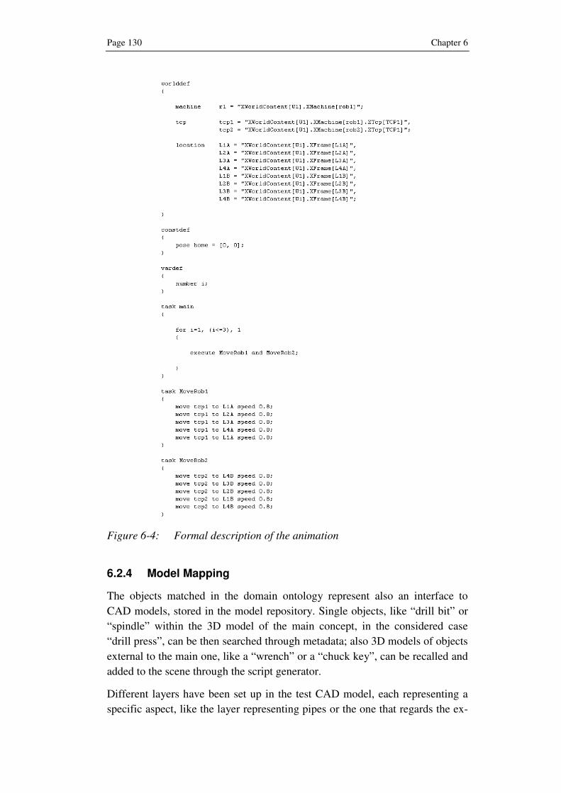
Page 130 Chapter 6
Figure 6-4: Formal description of the animation
6.2.4 Model Mapping
The objects matched in the domain ontology represent also an interface to
CAD models, stored in the model repository. Single objects, like “drill bit” or
“spindle” within the 3D model of the main concept, in the considered case
“drill press”, can be then searched through metadata; also 3D models of objects
external to the main one, like a “wrench” or a “chuck key”, can be recalled and
added to the scene through the script generator.
Different layers have been set up in the test CAD model, each representing a
specific aspect, like the layer representing pipes or the one that regards the ex-

Prototype Implementation and Validation Page 131
ternal case of a machine. Such layers can be set visible or invisible thus giving
a completely different result of the parts to be displayed: this is the essential
feature to allow the management of different roles, each of them needing a par-
ticular view of the whole training target. The link between CAD models reposi-
tory and ontology can be also allowed by an additional agent, responsible for
the management of the layers within the CAD model, according to the roles
defined in the domain ontology.
For the considered test case, due to the simplicity of the used CAD model, just
two views have been set up within the 3D model of the drill press (see figure 6-
5):
• Overall view, for the operations and sales roles
• Detailed view without case unit, for maintenance and assembly
roles
Figure 6-5: Views of the drill press model for different purposes
The approach followed in the implementation is to split the main model into
several subparts, which are at first converted into VRML files and then linked
as a reference to a standard XML file. In this way single parts can be named
according to the concept defined in the part ontology, thus allowing an easier
identification of the elements.
To reduce incoherencies and eventual misunderstanding, a first visual feedback
can be provided by the developed viewer, which lets the user check if the 3D
Page 132 Chapter 6
models of the displayed parts correspond to the real targets of the training ses-
sion.
6.2.5 Animation Script Generation
The generation of the animation script is demanded to a “script generator”, a
software agent, which according to the chosen 3D graphics file format, con-
verts the formal description into the animation script. The script itself repre-
sents the starting point to build the scene graph for the requested animations.
The chosen 3D graphics file format for the implementation is VRML, since all
major CAD providers offer tools to export in this format. Even if X3D repre-
sents the evolution of VRML, the support of CAD files still needs some devel-
opment in order to embed mature functionalities in the domain.
The agent, according to the previously defined formal description, interprets
the provided information and codes the animation description in terms of coor-
dinates and transformations, in XML notation. The animation script compre-
hends between its features:
• Translation, rotation and scaling of objects
• Change of the visual properties of an object: color, transparency, visi-
bility, etc.
• Viewpoint changes
Parallel to the visualization parameters, the script generator manages the time
parameters, like “startTime”, “Time” and “Delay”, according to standard pre-
defined values; such values can however be modified according to the feed-
back provided by the user after the visualization of the animation preview.
The created script represents in detail the operations to be performed during the
animation; together with the loading of the geometry, it concludes the anima-
tion authoring process, which is then able to visualize the requested animation
using an OpenGL-based viewer.
A continuous improvement of the authoring process is also provided to the
user, which can give some feedback at the end of the visualization of each sub-
task. The most important variables that need to be adjusted are the camera and
time management: therefore, the user can specify if the virtual camera was not
in an optimal position, i.e. too far or too close to the target object, as well as if
the animation times are too fast or too slow to get a good understanding of the
processes. The agent can thus vary the camera positioning parameters or time
and speed values in order to obtain an optimal visualization.

Prototype Implementation and Validation Page 133
6.3 Evaluation
The implementation introduced in this section has shown that a 3D Animation
can be created by means of a script, which derives from a natural language text,
and visualized in an interactive way through the corresponding viewer.
The tests performed to validate the proposed approach, once the prototype im-
plementation has been completed, have revealed that the method is able to sat-
isfy the initial requirements:
• Training animations have been created starting from natural language,
descriptions, which have been parsed and divided into subcategories on
a phrase level and on a verb level.
• Core of the method is the combined use of an upper ontology and of
one or multiple domain ontologies, which act as knowledge core for in-
terpreting natural language sentences.
• Different end user roles, together with their own information needs, can
be managed by the ontology.
• Animation atoms and events can be defined and managed through the
ontology, thus assuring reusability of some basic animations, also for
different user roles.
However, the automatic translation of a generic training sequence into the cor-
responding animation is still not mature enough; it is in fact bounded by many
variables, like the structure and content of the training sequence or the use of
external elements, e.g. a wrench key, just to mention the most common prob-
lems.
The main difficulty encountered is in the heterogeneity of the existing text-
based training material, contained for example in instruction manuals. This was
anyway expected for the following reasons:
• Each author has its own styles, therefore written training sequences dif-
fer according to the style adopted by the author
• Existing training material has not been created with the aim of the
automatic generation of 3D animation
• The use of multiple visualization modalities, including drawings and
other visual signs, connected with the text, complicates enormously the
parsing phase and therefore the whole authoring process.
The realization of “ad hoc” training sequences, which follows the guidelines
introduced by the proposed approach, is of course useful in order to solve the
problems mentioned above. In this way, also complex tasks can be subdivided

Page 134 Chapter 6
into smaller subtasks, which are easier to be translated into the corresponding
animation.

Summary and Outlook Page 135
7 Summary and Outlook
The fast development of the computer-based era has allowed the representation
of industrial products in a three-dimensional environment by means of 3D
CAD models. Such new approach has shift industrial applications, performed
in the past essentially through paper-based techniques and through the realiza-
tion of real scale models, to a completely digital 3D product representation,
like digital mock-ups as well as virtual and augmented reality for the product
development phase.
Also the training domain has exploited the benefits deriving from the 3D ap-
proach; trainees can nowadays experience the features of the real objects or
situations by exploring a virtual environment. In addition, the static 3D model
can be transformed into interactive 3D animations, which differently from pa-
per or video based training give an overall understanding of the task and of the
involved elements from different points of view. The trainee can in fact stop at
any time the animation, zoom in and out as well as get understanding of the
relations between parts and their movements.
The authoring of 3D animations for training purposes is a customized process,
usually realized by specialized 3D artists, which however are not expert in the
training target domain. The presence of expert staff, which explains technical
details, or the use of existing training material, like instruction manuals or ex-
ploded drawings, is therefore required in order to correctly identify technical
elements and understand actions to be represented within the animation. In
such situations the rising of a semantic problem is very probable: natural lan-
guage is not formal enough to unambiguously identify the correct elements as
well as to represent specific actions in the virtual scene. The sentence “remove
the screw”, for example, says nothing about the kind of screw neither the kind
of action, consisting in a rotation and a translation of the target object.
In the proposed research approach a series of requirements for the automating
the 3D animation authoring process has been deducted in order to solve the
problems mentioned above: they include 3D support, natural language under-
standing, the use of a knowledge-base system, the management of different end
user roles, and the reusability of animation atoms.
An innovative approach able to automate the authoring process of 3D anima-
tion for training purposes has been proposed. The process, consisting of five
phases, starts from existing or “ad hoc” created training sequences, expressed
in natural language, parses them by means of a natural language parser and
matches the found elements in an ontology core.

Page 136
Role of the ontology is to provide a link between syntactical elements included
in a generic training sentence and the corresponding concepts of parts and ac-
tions to be displayed in the 3D animation. Knowledge supplied by the ontol-
ogy, through hierarchies of concepts, relations and attributes, is able to mini-
mize the semantic problem.
The ontology core is made up of an upper ontology, which contains domain
independent knowledge in terms of basic concepts and relations, and represents
at the same time a common framework for the further definition of additional
ontologies. The development of one or multiple domain ontologies, subdivided
into parts and actions ontology, which contain specific knowledge of parts and
of actions performed through them, completes the structure of the ontology
core.
The domain ontology is also linked to a CAD models repository, thus allowing
a mapping of concepts regarding objects to their corresponding 3D models.
Once all relevant information has been collected, a script generator fills up a
standard animation template and generates the animation script, which allows
the display of the required animation through the corresponding viewer.
The proposed approach has proven to be feasible and to be able to satisfy the
preliminary requirements, thus making the 3D animation process easier and
faster, even if remaining fully customizable through the ontology: different
animation atoms as well as user roles can be defined and managed. However,
the approach is not mature enough and further development work is required,
mostly on the input of training sequences; they represent, in fact, with their
extremely different styles and contents, which are typical of natural language,
the bottleneck of the process method.
In order to further develop the proposed intelligent authoring of 3D animations
for training purposes, research work can proceed in the following directions:
Standardization of training sequence: since the training sequence, expressed
in a natural language form, represents the bottleneck of the whole process in
terms of efficiency, a standardization of the training sequence can improve and
speed up the whole process. This includes the definition of the structure of the
sequence as well as of each subtask, the use of simple verb-object sentences
and the presence of action verbs rather than abstract ones.
Development of further domain ontologies: the proposed approach is very
flexible since it is domain ontology depending. The development of additional
domain ontologies, for the automotive, aviation or construction domains, can
extend the possibilities of delivering customized 3D training animations for
various domains.
Summary and Outlook Page 137
Integration of domain ontology and model repository: the connection be-
tween the ontology and model repository, described in the proposed approach,
is represented by a link between two separate systems. However, an integrated
platform, including both systems, where every element of the model could be
joined to the corresponding concept, defined in the ontology, can guarantee the
correct identification of the parts and provide an immediate visual feedback
about the correctness of the whole process.
Management of adverbs and adjectives: the management of additional ele-
ments, like adjectives and adverbs, is absolutely necessary. However, a new
metaphor is needed since most of such elements have an abstract meaning,
which is impossible to be displayed within a 3D animation. A system of visual
signs or textual information can solve the problem and enrich the content of the
animation.
Voice interaction: even if the proposed approach manages the input of text-
based training sequence, a significant step forward is represented by the sup-
port of voice interaction. This implies the use of a reliable voice recognition
system, which translates voice commands into text to be sent to the natural
language parsing.

List of Figures Page 139
8 List of Figures
Figure 1-1: The product development process [GEK01] ........................ 5
Figure 1-2: Sequence from a 3D animation for the removal of fasteners
in an airplane’s landing gear brake ..................................................................... 6
Figure 2-1: Example of an Experience curve (logarithmic coordinates)
[Hen74-ol] .............................................................................................. 9
Figure 2-2: Different training modalities in the Dale’s Cone of
Experience ........................................................................................... 10
Figure 2-3: Milgram’s Continuum ........................................................ 12
Figure 2-4: VSOne virtual surgery [KCM+01] ..................................... 13
Figure 2-5: NASA 747 simulator [SS96] .............................................. 13
Figure 2-6: Military virtual reality applications: Virtual Combat Convoy
Trainer (up) and Virtual Reality Parachute Trainer (down) ............................. 14
Figure 2-7: Virtual Reality in a CAVE [Bar01-ol]................................ 15
Figure 2-8: Toy Story ............................................................................ 16
Figure 2-9: Final Fantasy....................................................................... 17
Figure 2-10: Gran turismo 4 .................................................................... 17
Figure 2-11: Screenshot of a virtual campus in Second Life .................. 18
Figure 2-12: 3D animations on Pocket PC.............................................. 20
Figure 2-13: CAD model of an ultra-light aircraft motor........................ 22
Figure 2-14: Storyboard of a 3D animation [LU-ol] ............................... 23
Figure 2-15: Key frames (in white) and interpolated frames (in blue).... 24
Figure 2-16: Combined transformation matrix........................................ 25
Figure 2-17: Phases of Product Lifecycle Management [AS06]............. 27
Figure 2-18: Modern woodworking manufacturing machine ................. 28
Figure 2-19: Technical drawing of an airplane’s landing gear................ 29
Figure 2-20: View of a whole manufacturing machine........................... 31
Figure 2-21: Detail of a spindle in a manufacturing machine ................. 32

Page 140
Figure 2-22: Example of a micro (left), a macro animation (middle) and
its inclusion in another macro animation (right) ...............................................33
Figure 3-1: Example of a scene graph [GEK01] ...................................40
Figure 3-2: Representation in VRML (left) and X3D (right) of the same
scene (down) ............................................................................................42
Figure 3-3: Example of picture generated from the text description.....44
Figure 3-4: Screenshot of a CarSim animation......................................45
Figure 3-5: Confucius architecture ........................................................47
Figure 3-6: Screenshot of the Rapid Manual Working Environment....49
Figure 3-7: Training sequence using Right Hemisphere .......................50
Figure 3-8: Training animation with Lattice3D.....................................51
Figure 3-9: Review of state-of-the-art in 3D authoring.........................53
Figure 4-1: Generic parse tree ...............................................................59
Figure 4-2: Extract from WordNet online results for the lemma “open 64
Figure 4-3: The blocks world task .........................................................69
Figure 4-4: Ontology deriving from Conceptualization 1 .....................70
Figure 4-5: Extract from ConceptNet ....................................................75
Figure 5-1: Overview of the basic idea of the proposed approach ........82
Figure 5-2: Upper Ontology and Domain Ontologies ...........................83
Figure 5-3: Extract of a mechanical device taxonomy ..........................87
Figure 5-4: Top down approach ............................................................88
Figure 5-5: Bottom-up approach ...........................................................89
Figure 5-6: Taxonomy of the Action Ontology.....................................92
Figure 5-7: Developed Process Model ..................................................97
Figure 5-8: Extract from a generic instruction manual..........................98
Figure 5-9: Ontology hierarchy ...........................................................100
Figure 5-10: Technical drawing of an airplane [PA-ol] ........................103
Figure 5-11: Parse tree of a sample training subtask .............................106
Figure 5-12: Verb matching through syntax..........................................109

List of Figures Page 141
Figure 5-13: Verb matching through alternative concepts .................... 110
Figure 5-14: Matching of the “Drill Bit” concept in an extract of the Part
Ontology ......................................................................................... 111
Figure 5-15: Screenshot of a PDM system............................................ 114
Figure 6-1: KoBaS knowledge based services .................................... 117
Figure 6-2: Extract of the definition for the concept “drill” in CYC ..119
Figure 6-3: Extract from the instruction manual [MM-ol].................. 125
Figure 6-4: Formal description of the animation................................. 130
Figure 6-5: Views of the drill press model for different purposes ...... 131


List of Tables Page 143
9 List of Tables
Table 4-1: Penn Treebank part-of-speech tags..................................... 60
Table 4-2: Semantic relations in WordNet........................................... 65
Table 4-3: Thematic roles .................................................................... 66
Table 4-4: Framenet elements .............................................................. 67
Table 4-5: A couple of possible conceptualizations of the world........ 69
Table 4-6: ConceptNet relations .......................................................... 76
Table 4-7: Concepts included in task ontology for a scheduling task.. 77
Table 5-1: Basic elements of the upper ontology................................. 84
Table 5-2: Relations on conceptual level ............................................. 89
Table 5-3: Spatial and functional relations .......................................... 90
Table 5-4: Action Ontology Relations ................................................. 93
Table 5-5: Spatial prepositions............................................................. 94
Table 5-6: Result of the parsing ......................................................... 106
Table 6-1: An extract of the drill press domain ontology .................. 122
Table 6-2: An extract of the defined “action on object” verbs .......... 123


Bibliography Page 145
10 Bibliography
[AL02] ASHBURNER, M.; LEWIS, S.: On ontologies for biologists: the Gene Ontology--untangling the web, Novartis Found Symp, 2002
[AS06] ABRAMOVICI, M.; SCHULTE, S.: PLM – State of the Art and Trends, Inovacoes Tecnologicas no Desenolvimento do Produto, 11. Inter-nationales Hochtechnologie Symposium „Technologische Innova-tionen Produktentwicklung“, 2006, pp. 27-49
[ASS+03] ÅKERBERG, O., SVENSSON H., SCHULZ B., NUGUES P.: CarSim: an automatic 3D text-to-scene conversion system applied to road ac-cident reports, Proceedings of the tenth conference on European chapter of the Association for Computational Linguistics, Volume 2, 2003, pp. 191–194
[Bar01-ol] Barco: MoVE PSA, France, 2001 at http://www.barco.com/virtualreality/en/references
[BFL98] BAKER, C.F.; FILLMORE, C.J.; LOWE, J.B.: The Berkeley FrameNet project, proceedings of the COLING-ACL, Montreal, Canada, 1998.
[BHK+97] BRANTS, T.; HENDRIKS, R.; KRAMP, S.; KRENN, B.; PREIS, C.; SKUT, W.; USZKOREIT, H.: Das negra-annotationsschema, Negra project report, Universität des Saarlandes, Saarbrücken, 1997
[BHL01] BERNERS-LEE, T.; HENDLER, J.; LASSILA, O.: The Semantic Web, Scientific American, 2001.
[BO05] BURNS, D.; OSFIELD, R.: Openscenegraph at http://www.openscenegraph.org, 2005.
[Boo69] BOOTH, T.L.: Probabilistic representation of formal languages, IEEE Conference Record of the 1969 Tenth Annual Symposium on Switching and Automata Theory, 1969, pp. 74-81
[Bor97] BORST, P.: Construction of Engineering Ontologies for Knowledge Sharing and Reuse, PhD thesis, Tweente University, 1997
[Bro05] BROGLIA, M.: Script language for industrial complex simulation (SICS), user manual v. 1.1, 2005
[Chi07] CHIANG, D.: Hierarchical Phrase-Based Translation, Computational Linguistics 33, 2, 2007, pp. 201-228
[CHJ+98] CHEN, W.; HAYASHI, Y.; JIN, L.; IKEDA, M.; MIZOGUCHI, R.: An Ontol-ogy-based Intelligent Authoring Tool, Proceedings of ICCE'98, Bei-jing, China,1998, pp.41-49
[Chk06] CHKLOVSKI, T.: Deriving quantitative overviews of free text assess-ments on the web, Proceedings of the 11th international Confer-ence on intelligent User interfaces. IUI '06. ACM Press, New York, NY, 2006, pp. 155-162
[CS01] COYNE, B.; SPROAT, R.: WordsEye: An Automatic Text--to--Scene Conversion System, Proceedings. of the 28th Annual Conf. on Computer Graphics and Interactive Techniques (SIGGRAPH 2001), 12--17 August 2001, Los Angeles, CA, pp. 487-496.
Page 146 Bibliography
[CSD93] CRUZ-NEIRA C.; SANDIN D.J.; DEFANTI T.A.: Surround-screen projec-tion-based virtual reality: the design and implementation of the CAVE, Proceedings of the 20th annual conference on Computer graphics and interactive techniques table of contents 1993, pp. 135 – 142
[Dal46] DALE, E.: Audio-visual methods in teaching, New York: The Dryden Press, 1946.
[DS04-ol] DEAN, M.; SCHREIBER, G.: OWL Web Ontology Language Refer-ence,W3C Recommendation at http://www.w3.org/TR/
[DSK+06] DÜNSER, A.; STEINBÜGL, K.; KAUFMANN, H.; GLÜCK, J.: Virtual and augmented reality as spatial ability training tools. In Proceedings of the 7th ACM SIGCHI New Zealand Chapter's international Confer-ence on Computer-Human interaction: Design Centered HCI CHINZ '06, vol. 158. ACM Press, New York, NY, 2006, pp. 125-132
[Ebb97] EBBESMEYER, P.: Dynamische Texturwände – Ein Verfahren zur echtzeit-orientierten Bildgenerierung für virtuelle Umgebungen technischer Objekte, PhD Thesis, Heinz Nixdorf Institut, Universität Paderborn, 1997
[FFR96] FARQUHAR, A.; FIKES, R.; RICE, J.: The Ontolingua server: A tool for collaborative ontology construction, Technical report, Stanford KSL 96-26, 1996
[Fil85] FILLMORE, C.J.: Frames and the semantics of understanding. Quaderni di Semantica, VI(2), 1985, pp. 222-254
[FK79] FRANCIS, W. N.; KUCERA, H.: Brown Corpus Manual, Department of Linguistics, Brown University, 1979
[Gee03] GEE, J. P.: What Video Games Have to Teach Us About Learning and Literacy, Palgrave MacMillan, NY, 2003
[GEK01] GAUSEMEIER, J.; EBBESMEYER, P.; KALLMEYER, F.: Produktinnovation – Strategische Planung und Entwicklung der Produkte von morgen, Carl Hanser Verlag, München, 2001
[GF92] GENESERETH, M. R.; FIKES, R. E.: Knowledge Interchange Format, Version 3.0 Reference Manual. Computer Science Department, Stanford University, Technical Report Logic-92-1, June 1992
[GHM92] GODFREY, J.J.; HOLLIMAN, E.C.; MCDANIEL J.: SWITCHBOARD: Telephone speech corpus for research and development, Proceed-ings of ICASSP, San Francisco, 1992, pp. 517-520
[GN87] GENESERETH M.; NILSSON N.: Logical foundations of artificial intelli-gence, Morgan Kaufmann Publishers Inc. San Francisco, CA, USA, 1987
[Gru93] GRUBER, T.R.: A Translation Approach to Portable Ontology Speci-fication. Knowledge Acquisition5: 199-220, 1993
[GSH+05] GABBARD, J.L.; SWAN, J.E.; HIX, D.; SCHULMAN, R.S.; LUCAS, J.; GUPTA, D.: An empirical user-based study of text drawing styles and outdoor background textures for augmented reality, Proceed-ings of IEE VR 2005, Bonn.
[Gua98] GUARINO, N.: Some Ontological Principles for Designing Upper Level Lexical Resources. Proc. of the First International Confer-ence on Lexical Resources and Evaluation, Granada, Spain, 1998

Bibliography Page 147
[HBH+00] HAJIČ, J.; BÖHMOVÁ, A.; HAJIČOVÁ, E.; VIDOVÁ HLADKÁ, B.: "The Pra-gue Dependency Treebank: A Three-Level Annotation Scenario". In: A. Abeillé (ed.): Treebanks: Building and Using Parsed Corpora, Amsterdam:Kluwer, 2000, pp. 103-127
[Hen74-ol] HENDERSON, B.D.: The Experience Curve - Reviewed - I. The Con-cept, Boston Consulting Group, 1974
[Her86] HERSKOVITZ, A.: Language and Spatial Cognition: An Interdiscipli-nary Study of the Prepositions in English. Cambridge University Press, Cambridge, 1986.
[HGD90] HEMPHILL, C. T.; GODFREY, J. J.; DODDINGTON, G. R.: The ATIS spo-ken language systems pilot corpus. Proceedings of the Workshop on Speech and Natural Language Human Language Technology Conference. Association for Computational Linguistics, Morristown, NJ, 1990, pp. 96-101
[HW96] HARTMAN, J.; WERNECKE J.: The VRML 2.0 Handbook – Building Moving Worlds on the Web. Silicon Graphics, Inc. Harlow, Eng-land: Addison-Wesley Publishing Company, 1996
[JIM96] JIN, L; IKEDA, M.; MIZOGUCHI, R.: Ontological Issues on Computer-based Training, PRICAI-96 Workshop on Knowledge-based In-structional Systems in an Industrial Setting, 1996, pp. 55-66
[JIM+97] JIN, L.; IKEDA, M.; MIZOGUCHI, R.; TAKAOKA, Y.: Role Explication of Simulation in Intelligent Training Systems by Training Task Ontol-ogy, Proceedings of AI-ED-97 Workshop on Architectures for intel-ligent simulation-based learning environments,1997, pp 41-48
[JM00] JURAFSKY, D.; MARTIN, J. H.: Speech and language processing: An Introduction to Natural Language Processing, Computational Lin-guistics, and Speech Recognition. Prentice-Hall, 2000, ISBN: 0-13-095069-6
[Joh83] JOHNSON-LAIRD, P.N.: Mental models, Harvard University Press, Cambridge MA, 1983
[JWB+04] JOHANSSON R.; WILLIAMS D.; BERGLUND A.; NUGUES P.: Carsim: A System to Visualize Written Road Accident Reports as Animated 3D Scenes- ACL2004: Second Workshop on Text Meaning and In-terpretation, 2004
[KCM+01] KÜHNAPFEL U.; ÇAKMAK H.K.; MAASS H.; WALDHAUSEN, S.: Models for simulating instrument-tissue interactions, 9th Medicine Meets Virtual Reality 2001 (MMVR 2001), Newport Beach, CA, USA, 2001
[KM02] KLEIN, D.; MANNING, C.D.: Fast Exact Inference with a Factored Model for Natural Language Parsing, Advances in Neural Informa-tion Processing Systems 15 (NIPS 2002), 2002
[KM03] KLEIN, D.; MANNING, C.D.: Accurate Unlexicalized Parsing, Pro-ceedings of the 41st Meeting of the Association for Computational Linguistics, 2003
[Lan89] LANIER, J.: Virtual reality: an interview with Jaron Lanier. Interview by Adam Heilbrun and Barbara Stacks (additional material by Kevin Kelly), volume 64, page 108 (12), Whole Earth Review, 1989
[LS04] LIU, H.; SINGH, P.: Commonsense Reasoning in and over Natural Language Proceedings of the 8th International Conference on

Page 148 Bibliography
Knowledge-Based Intelligent Information & Engineering Systems (KES'2004). Wellington, New Zealand, 2004
[LU-ol] Luleå University of Technology, Industrial Design at http://www.luth.se/
[Mar98] MAROLD, K. A.: From CAI to WBT: the evolution of electronic tute-lage, Proceedings of the International Business Schools Comput-ing Association Conference, Denver, CO, July11, 1998
[Mat05] MATYSCZOK,C.: Dynamische Kantenextraction – Ein Verfahren zur Generierung von Tracking-Informationen für Augmented-Reality-Anwendungen auf Basis von 3D-Referenzmodellen, PhD Thesis, Heinz Nixdorf Institut, Universität Paderborn, 2005
[MBF+90] MILLER, G.A.; BECKWITH, R.; FELLBAUM, C.; GROSS, D. AND MILLER, K.J.: Introduction to WordNet: An On-line Lexical Database, Inter-national Journal of Lexicography 1990, Volume 3 Number 4; pp. 235-244
[Min80] MINSKY, M.: K-lines: A Theory of Memory, Cognitive Science, Vol. 4, No. 2, 1980, pp. 117-133
[Miz03] MIZOGUCHI, R.: Tutorial on ontological engineering - Part 1: Intro-duction to Ontological Engineering, New Generation Computing, OhmSha & Springer, Vol.21, No.4, 2003, pp. 365-384
[MKS+00] MIZOGUCHI, R.; KOZAKI, K.; SANO, T.; KITAMURA, Y.: Construction and Deployment of a Plant Ontology, Knowledge Engineering and Knowledge Management - Methods, Models and Tools -, The 12th International Conference, EKAW2000, Lecture Notes in Artificial In-telligence 1937, Springer-Verlag, 2000, pp.113-128
[MM03] MA, E.; MC KEVITT, P.: Semantic representation of events in 3D animation, Proceedings of The Fifth International Workshop on Computational Semantics (IWCS-5), 2003, pp. 253-281
[MM04] MA M.; MCKEVITT P.: Visual Semantics and Ontology of Eventive Verbs. IJCNLP 2004, First International Joint Conference, Hainan Island, China, 2004, pp. 187-196
[MM-ol] Micro-Mark, Operating Instructions for MicroLux Drill Press at http://www.micromark.com/html_pages/instructions/81631i/drill_press.html
[MMR+55] MCCARTHY, J.; MINKSY, M.; ROCHESTER, N.;SHANNON, C.: A Pro-posal for the Dartmouth Summer Research, Project on Artificial in-telligence, Technical report, 1955
[MSI96] MIZOGUCHI, R.; SINITSA, K.; IKEDA, M.: Task Ontology Design for Intelligent Educational/Training Systems, Proceedings of Work-shop on "Architectures and Methods for Designing Cost-Effective and Reusable ITSs,", ITS'96, Montreal, 1996, pp.1-21
[MTU+94] MILGRAM, P.; TAKEMURA, H.; UTSUMI, A.; KISHINO, F.: Augmented Reality: A class of displays on the reality-virtuality continuum". SPIE Vol. 2351-34, Telemanipulator and Telepresence Technolo-gies, 1994
[Ond05] ONDREJKA, C.: Changing Realities: User Creation, Communication, and Innovation in Digital Worlds, White Paper, Linden Lab, 2005
[PA-ol] Parallelgraphics at www.cortona3d.com

Bibliography Page 149
[Par02] PARISI, S.: A method for the representation of assembly processes on mobile devices, Diploma thesis, Heinz Nixdorf Institutm UNiver-sität Paderborn, 2002
[PD04] Persson L., Danielsson M.; Name extraction in car accident reports for Swedish, Technical report, LTH Lund, 2004
[Pit94] PITO, R.: Tgrep Manual, 1994
[PO02] The Plant Ontology Consortium and Plant Ontologies, Comparative and Functional Genomics, 2002, Vol 3(2), pp. 137-142.
[Ray03] RAYBOURN, E. M.: Design Cycle Usability and Evaluations of an Intercultural Virtual Simulation Game for Collaborative Virtual Learning, C. Ghaoui (Ed.), Usability Evaluation of Online Learning Programs, Information Science Publishing, 2003, pp. 233-253
[RH05-ol] Right Hemisphere, Product Graphics Management for Interactive 3D Training White Paper, 2005 at http://www.righthemisphere.com/
[RM03] Rosse, C.; Mejino, J.V.L.: A reference ontology for bioinformatics: the Foundational Model of Anatomy. Journal of Biomedical Infor-matics, 36, 2003, pp. 478-500
[RMN+00] RESCONI, G.; MURAI, T.; NAKATA, M.; SHIMBO, M.: Semantic field: introduction. Proceedings. Fourth International Conference on Knowledge-Based Intelligent Engineering Systems and Allied Technologies, Volume 2, 2000 pp. 483 - 486 vol.2
[Roh01] ROHDE, D.: Tgrep2 user manual, 2001
[Ros02] ROSENBERG, M. J.: E-Learning: Strategies for Delivering Knowl-edge in the Digital Age. McGraw-Hill, Inc., 2002
[Rog95] ROGET, P.M.: Roget’s II: The New Thesaurus, Third Edition, Houghton Mifflin Company, 1995
[RS95] RUSSEL S., NORVIG P.: Artificial Intelligence, a modern approach, Prentice Hall Series in Artificial Intelligence. Englewood Cliffs, New Jersey, 1995.
[SA73] SCHANK, R.C.; ALBELSON, R.P.: Scripts, Plans, Goals and Under-standing, Lawrence Erlbaum, Hillsdale, NJ, 1973
[Sal69] SALOMAA, A.: Probabilistic and weighted grammars, Information and control, 15, 1969, pp. 529-544
[Sam95] SAMPSON, G.: English for the Computer: The Susanne Corpus and Analytic Scheme, Clarendon Press, 1995
[SDC+05] SIDHU, A.S.; DILLON, T.S.; CHANG, E.; SIDHU, B.S.: Protein Ontology: Vocabulary for Protein Data, 3rd International IEEE Conference on Information Technology and Applications (IEEE ICITA 2005). Syd-ney, 2005
[SGT+00] SCHLENOFF, C.; GRUNINGER M.; TISSOT, F.; VALOIS, J.; LUBELL, J.; LEE, J.: The Process Specification Language (PSL): Overview and Version 1.0 Specification," NISTIR 6459, National Institute of Stan-dards and Technology, Gaithersburg, MD., 2000
[Sow00] SOWA J.F.: Knowledge Representation: Logical, Philosophical, and Computational Foundations, Brooks Cole Publishing Co., Pacific Grove, CA, 2000

Page 150 Bibliography
[SS96] SULLIVAN, B.T.; SOUKUP P.A.: The NASA 747-400 flight simulator - A national resource for aviation safety research, AIAA Flight Simu-lation Technologies Conference, San Diego, CA, 1996
[TF04] TARAU, P.; FIGA, E.: Knowledge-based conversational agents and virtual storytelling. Proceedings of the 2004 ACM Symposium on Applied Computing, ACM Press, New York, NY, 2004, pp. 39-44
[TNT+04] TSAMPOULATIDIS, I.; NIKILAKIS, G.; TZOVARAS, D.; STRINTZIS, M.G.: Ontology based interactive graphic environment for product pres-entation, Proceedings of Computer Graphics International, 2004, pp. 644 – 647
[UG96] USCHOLD, M.; GRUNINGER, M.: Ontologies: Principles, Methods and Applications. KnowledgeEngineering Review11
[UJ99] USCHOLD, M.; JASPER, R.: A Framework for Understanding and Classifying Ontology Applications. In Proceedings of the IJCAI-99 Workshop on Ontologies and Problem-Solving Methods (KRR5), Stockholm, Sweden, 1999
[WYH+00] WAKITA, A.; YAJIMA, M.; HARADA, T.; TORIYA, H.; CHIYOKURA, H.: XVL®: A Compact and Qualified 3D Representation With Lattice Mesh and Surface for the Internet, ACM Web3D-VRML2000 Con-ference, Monterey, California, ACM, SIGGRAPH and SIGCOMM, Feb. 21-24, ACM-Press, 2000