
Air-Conditioners INDOOR UNIT PEFY-P15,P20,P25,P32,P40,P50 ...€¦ ·...
13
Air-Conditioners INDOOR UNIT PEFY-P15,P20,P25,P32,P40,P50,P63 VMS1-E PEFY-P15,P20,P25,P32,P40,P50,P63 VMS1L-E GB INSTALLATION MANUAL For safe and correct use, please read this installation manual thoroughly before installing the air-conditioner unit. INSTALLATIONSHANDBUCH Zum sicheren und ordnungsgemäßen Gebrauch der Klimageräte das Installationshandbuch gründlich durchlesen. MANUEL D’INSTALLATION Veuillez lire le manuel d’installation en entier avant d’installer ce climatiseur pour éviter tout accident et vous assurer d’une utilisation correcte. MANUAL DE INSTALACIÓN Para un uso seguro y correcto, lea detalladamente este manual de instalación antes de montar la unidad de aire acondicionado. MANUALE DI INSTALLAZIONE Per un uso sicuro e corretto, leggere attentamente questo manuale di installazione prima di installare il condizionatore d’aria. INSTALLATIEHANDLEIDING Voor een veilig en juist gebruik moet u deze installatiehandleiding grondig doorlezen voordat u de airconditioner installeert. MANUAL DE INSTALAÇÃO Para segurança e utilização correctas, leia atentamente este manual de instalação antes de instalar a unidade de ar condicionado. E°XEIPI¢IO O¢H°IøN E°KATA™TA™H™ °È· ·ÛÊ¿ÏÂÈ· Î·È ÛˆÛÙ‹ ¯Ú‹ÛË, ·Ú·Î·Ï›ÛÙ ‰È·‚¿ÛÂÙ ÚÔÛ¯ÙÈο ·˘Ùfi ÙÔ ÂÁ¯ÂÈÚ›‰ÈÔ ÂÁηٿÛÙ·Û˘ ÚÈÓ ·Ú¯›ÛÂÙ ÙËÓ ÂÁηٿÛÙ·ÛË Ù˘ ÌÔÓ¿‰·˜ ÎÏÈÌ·ÙÈÛÌÔ‡. РУКОВОДСТВО ПО УСТАНОВКЕ Для осторожного и правильного использования прибора необходимо тщательно ознакомиться с данным руководством по установке до выполнения установки кондиционера. MONTAJ ELK‹TABI Emniyetli ve do¤ru biçimde nas›l kullan›laca¤›n› ö¤renmek için lütfen klima cihaz›n› monte etmeden önce bu elkitab›n› dikkatle okuyunuz. PO HG SV CZ TR RU GR P NL I E F D SL
Transcript of Air-Conditioners INDOOR UNIT PEFY-P15,P20,P25,P32,P40,P50 ...€¦ ·...

Air-ConditionersINDOOR UNITPEFY-P15,P20,P25,P32,P40,P50,P63 VMS1-EPEFY-P15,P20,P25,P32,P40,P50,P63 VMS1L-E
GB
INSTALLATION MANUALFor safe and correct use, please read this installation manual thoroughly before installing the air-conditioner unit.
INSTALLATIONSHANDBUCHZum sicheren und ordnungsgemäßen Gebrauch der Klimageräte das Installationshandbuch gründlich durchlesen.
MANUEL D’INSTALLATIONVeuillez lire le manuel d’installation en entier avant d’installer ce climatiseur pour éviter tout accident et vous assurer d’une utilisation correcte.
MANUAL DE INSTALACIÓNPara un uso seguro y correcto, lea detalladamente este manual de instalación antes de montar la unidad de aire acondicionado.
MANUALE DI INSTALLAZIONEPer un uso sicuro e corretto, leggere attentamente questo manuale di installazione prima di installare il condizionatore d’aria.
INSTALLATIEHANDLEIDINGVoor een veilig en juist gebruik moet u deze installatiehandleiding grondig doorlezen voordat u de airconditioner installeert.
MANUAL DE INSTALAÇÃOPara segurança e utilização correctas, leia atentamente este manual de instalação antes de instalar a unidade de ar condicionado.
E°XEIPI¢IO O¢H°IøN E°KATA™TA™H™°È· ·ÛÊ¿ÏÂÈ· Î·È ÛˆÛÙ‹ ¯Ú‹ÛË, ·Ú·Î·Ï›ÛÙ ‰È·‚¿ÛÂÙ ÚÔÛ¯ÙÈο ·˘Ùfi ÙÔ ÂÁ¯ÂÈÚ›‰ÈÔ ÂÁηٿÛÙ·Û˘ ÚÈÓ ·Ú¯›ÛÂÙ ÙËÓÂÁηٿÛÙ·ÛË Ù˘ ÌÔÓ¿‰·˜ ÎÏÈÌ·ÙÈÛÌÔ‡.
РУКОВОДСТВО ПО УСТАНОВКЕДля осторожного и правильного использования прибора необходимо тщательно ознакомиться с данным руководством поустановке до выполнения установки кондиционера.
MONTAJ ELK‹TABIEmniyetli ve do¤ru biçimde nas›l kullan›laca¤›n› ö¤renmek için lütfen klima cihaz›n› monte etmeden önce bu elkitab›n› dikkatle okuyunuz.
PO
HG
SV
CZ
TR
RU
GR
PN
LI
EF
DS
L
KB79H130H01_cv_16lang.p65 07.5.28, 3:58 PM3
3 3.2[Fig. 3.2.1]
4 4.1[Fig. 4.1.1]
A Refrigerant pipe (liquid pipe): HP
B Refrigerant pipe (gas pipe): LP
C Drain pipe (O.D. ø32) * only on the PEFY-P·VMS1-E model
D Drain pipe (O.D. ø32, spontaneous draining)
A Unit body
B Lifting machine
C Nuts (field supply)
D Washers (accessory)
E M10 hanging bolt (field supply)
5 5.2
[Fig. 5.1.1] [Fig. 5.1.2] [Fig. 5.2.1]
5.1
6 6.2[Fig. 6.2.1]
2
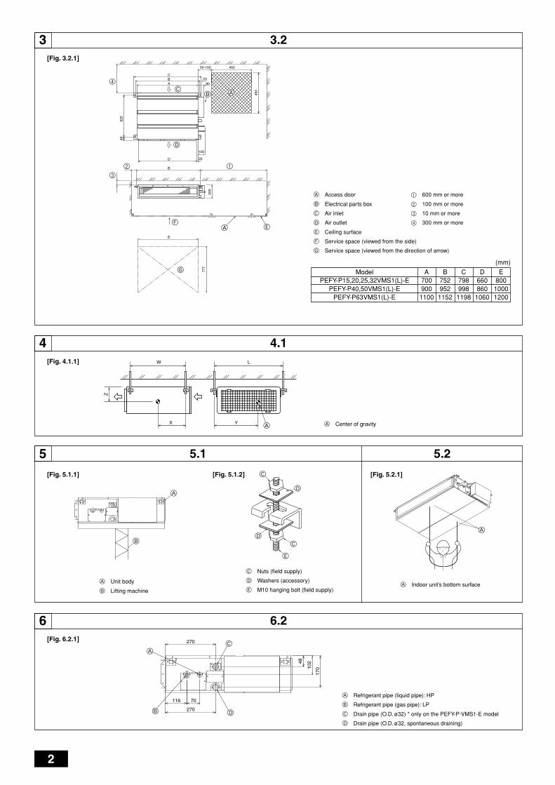
A Center of gravity
A Access door
B Electrical parts box
C Air inlet
D Air outlet
E Ceiling surface
F Service space (viewed from the side)
G Service space (viewed from the direction of arrow)
1 600 mm or more
2 100 mm or more
3 10 mm or more
4 300 mm or more
A Indoor unit’s bottom surface
YX
LW
A
Z
B
A
A
A
B
C
D
270
17010
248
270
116 70
BC
D
AF
G
3
4
E
A
50~150 450
450
4962
5
777
20
100
9023
CBA
D
B
E
200
12
C
D
C
E
D
(mm)
ModelPEFY-P15,20,25,32VMS1(L)-E
PEFY-P40,50VMS1(L)-EPEFY-P63VMS1(L)-E
A7009001100
B7529521152
C7989981198
D660860
1060
E80010001200
KB79H130H01-p02 07.4.25, 4:33 PM2
3
A Cut here
B Remove brazed cap
A
A
E
C
F
B
D
A Thermal insulation
B Pull out insulation
C Wrap with damp cloth
D Return to original position
E Ensure that there is no gap here
F Wrap with insulating tape
7[Fig. 7.1.1]
7.1
[Fig. 7.1.3]
B
J
O
N
F
Max. 300mm
[Fig. 7.2.1]
Correct piping
Wrong piping
A Insulation (9 mm or more)
B Downward slope (1/100 or more)
C Support metal
K Air bleeder
L Raised
M Odor trapGrouped piping
D O. D. ø32 PVC TUBE
E Make it as large as possible. About 10 cm.
F Indoor unit
G Make the piping size large for grouped piping.
H Downward slope (1/100 or more)
I O. D. ø38 PVC TUBE for grouped piping.(9 mm or more insulation)
PEFY-P·VMS1-E model
J Up to 550 mm
N Drain hose (accessory)
O Horizontal or slightly upgradient
7.2
[Fig. 7.2.2]
C
BA
L
DD DE
K
MB
H I
Max. 20m
1.5-2m
GFF F
B
C D E EH
G
KJ
F
I
A
2535 25
A Indoor unit
B Insulation pipe (long) (accessory)
C Tie band (accessory)
D Visible part
E Insertion margin
F Drain hose (accessory)
G Drain pipe (O.D. ø32 PVC TUBE, field supply)
H Insulating material (field supply)
I Tie band (accessory)
J Max.180 ± 5 mm
K To be gap free. The joint section of the insulation material meet must beat the top.
A
[Fig. 7.1.2]
A Cool by a wet cloth
[Fig. 7.2.3]
A Indoor unit
B Insulation pipe (short) (accessory)
C Tie band (accessory)
D Band fixing part
E Insertion margin
F Drain hose (accessory)
G Drain pipe (O.D. ø32 PVC TUBE, field supply)
H Insulating material (field supply)
I Max.145 ± 5 mm
D EH
GI
FB
C
5 25
A
KB79H130H01-illust 07.4.25, 4:32 PM3
4
A Air inlet
B Air outlet
C Access door
D Ceiling surface
E Canvas duct
F Air filter
G Inlet grille
A B D E
C C C C C C C
8[Fig. 8.0.1]
9 9.1[Fig. 9.1.1] [Fig. 9.2.1]
[Fig. 9.2.2]
TB5 TB5
SM1M2 SM1M2
TB3
M1M2
AAB
CC
TB5 TB15 TB5 TB15
SM1M2 SM1M2
TB3
M1M2 21 21
AAB
CC
F
G
E
D C
B A
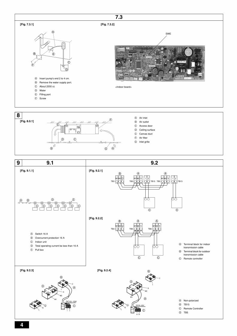
A Switch 16 A
B Overcurrent protection 16 A
C Indoor unit
D Total operating current be less than 16 A
E Pull box
A Terminal block for indoortransmission cable
B Terminal block for outdoortransmission cable
C Remote controller
A Non-polarized
B TB15
C Remote Controller
D TB5
[Fig. 9.2.3] [Fig. 9.2.4]
2
S
M2
M1
A
B
D1
DC10~13V
A B1 2L
NC
D
A
S
M2
M1
B
1
2
LN
DC24~30V
(A, B)1 2
C
9.2
[Fig. 7.3.1]
7.3
A
B
FC
D
E
A Insert pump's end 2 to 4 cm.
B Remove the water supply port.
C About 2000 cc
D Water
E Filling port
F Screw
[Fig. 7.3.2]
SWE
<Indoor board>
KB79H130H01-illust 07.4.25, 4:32 PM4
5
E Use PG bushing to keep the weight of the cable and external force from beingapplied to the power supply terminal connector. Use a cable tie to secure thecable.
F Power source wiring
G Tensile force
H Use ordinary bushing
I Transmission wiring
J Power source terminal bed
K Terminal bed for indoor transmission
L Terminal bed for remote controller
M To 1-phase power source
N Transmission line DC 30 V
O Terminal bed for outdoor transmission line (TB3)
P Transmission line to the remote controller, terminal bed for indoor unit andBC controller
A Terminal bed
B Round terminal
C Shield wire
D The earth wire from two cables are connected together to the S terminal. (Dead-end connection)
E Insulation tape (To keep the earth wire of the shielded cable from coming in contact with the transmis-sion terminal)
<Address board>
9.3
[Fig. 9.3.3] [Fig. 9.3.4]
[Fig. 9.5.1]
[Fig. 9.3.5]
9.5
A Terminal bed box
B Knockout hole
C RemoveA Screw holding cover (2pcs)
B Cover
[Fig. 9.3.1] [Fig. 9.3.2]
A
B
C
A
B
M2M1
KJ
P
L
N
O
M1 M2 S 1 2
LN M
N
LE
F
GI
H
M2 SM1 A
B
C
E
D
A
C
FD BE
2
1
A SWA
B SWC
C SW1
D SW11
E SW12
F SW14
KB79H130H01-illust 07.4.26, 4:18 PM5
6
GB
DF
EI
NL
PG
RR
UT
RC
ZS
VH
GP
O
Contents
1. Safety precautions
1.1. Before installation and electric work
s Before installing the unit, make sure you read all the “Safetyprecautions”.
s The “Safety precautions” provide very important points re-garding safety. Make sure you follow them.
Symbols used in the text
Warning:Describes precautions that should be observed to prevent danger of injuryor death to the user.
Caution:Describes precautions that should be observed to prevent damage to theunit.
Symbols used in the illustrations: Indicates an action that must be avoided.
: Indicates that important instructions must be followed.
: Indicates a part which must be grounded.
: Indicates that caution should be taken with rotating parts. (This symbol isdisplayed on the main unit label.) <Color: Yellow>
: Beware of electric shock (This symbol is displayed on the main unit label.)<Color: Yellow>
Warning:Carefully read the labels affixed to the main unit.
Warning:• Ask the dealer or an authorized technician to install the air conditioner.
- Improper installation by the user may result in water leakage, electric shock,or fire.
• Install the air unit at a place that can withstand its weight.- Inadequate strength may cause the unit to fall down, resulting in injuries.
• Use the specified cables for wiring. Make the connections securely sothat the outside force of the cable is not applied to the terminals.- Inadequate connection and fastening may generate heat and cause a fire.
• Prepare for typhoons and other strong winds and earthquakes and in-stall the unit at the specified place.- Improper installation may cause the unit to topple and result in injury.
• Always use an air cleaner, humidifier, electric heater, and other accesso-ries specified by Mitsubishi Electric.- Ask an authorized technician to install the accessories. Improper installation
by the user may result in water leakage, electric shock, or fire.• Never repair the unit. If the air conditioner must be repaired, consult the
dealer.- If the unit is repaired improperly, water leakage, electric shock, or fire may
result.• Do not touch the heat exchanger fins.
- Improper handling may result in injury.• When handling this product, always wear protective equipment.
EG: Gloves, full arm protection namely boiler suit, and safety glasses.- Improper handling may result in injury.
• If refrigerant gas leaks during installation work, ventilate the room.- If the refrigerant gas comes into contact with a flame, poisonous gases will
be released.
• Install the air conditioner according to this Installation Manual.- If the unit is installed improperly, water leakage, electric shock, or fire may
result.• Have all electric work done by a licensed electrician according to “Elec-
tric Facility Engineering Standard” and “Interior Wire Regulations”andthe instructions given in this manual and always use a special circuit.- If the power source capacity is inadequate or electric work is performed im-
properly, electric shock and fire may result.• Keep the electric parts away from water (washing water etc.).
- It might result in electric shock, catching fire or smoke.• Securely install the outdoor unit terminal cover (panel).
- If the terminal cover (panel) is not installed properly, dust or water may enterthe outdoor unit and fire or electric shock may result.
• When installing and moving the air conditioner to another site, do notcharge the it with a refrigerant different from the refrigerant specified onthe unit.- If a different refrigerant or air is mixed with the original refrigerant, the refrig-
erant cycle may malfunction and the unit may be damaged.• If the air conditioner is installed in a small room, measures must be taken
to prevent the refrigerant concentration from exceeding the safety limiteven if the refrigerant should leak.- Consult the dealer regarding the appropriate measures to prevent the safety
limit from being exceeded. Should the refrigerant leak and cause the safetylimit to be exceeded, hazards due to lack of oxygen in the room could result.
• When moving and reinstalling the air conditioner, consult the dealer oran authorized technician.- If the air conditioner is installed improperly, water leakage, electric shock, or
fire may result.• After completing installation work, make sure that refrigerant gas is not
leaking.- If the refrigerant gas leaks and is exposed to a fan heater, stove, oven, or
other heat source, it may generate noxious gases.• Do not reconstruct or change the settings of the protection devices.
- If the pressure switch, thermal switch, or other protection device is shortedand operated forcibly, or parts other than those specified by Mitsubishi Elec-tric are used, fire or explosion may result.
• To dispose of this product, consult your dealer.• Do not use a leak detection additive.
1.2. Precautions for devices that use R410Aor R407C refrigerant
Caution:• Do not use the existing refrigerant piping.
- The old refrigerant and refrigerator oil in the existing piping contains a largeamount of chlorine which may cause the refrigerator oil of the new unit todeteriorate.
• Use refrigerant piping made of C1220 (Cu-DHP) phosphorus deoxidizedcopper as specified in the JIS H3300 “Copper and copper alloy seamlesspipes and tubes”. In addition, be sure that the inner and outer surfaces ofthe pipes are clean and free of hazardous sulphur, oxides, dust/dirt, shav-ing particles, oils, moisture, or any other contaminant.- Contaminants on the inside of the refrigerant piping may cause the refriger-
ant residual oil to deteriorate.• Store the piping to be used during installation indoors and keep both
ends of the piping sealed until just before brazing. (Store elbows andother joints in a plastic bag.)- If dust, dirt, or water enters the refrigerant cycle, deterioration of the oil and
compressor trouble may result.
1. Safety precautions ...................................................................................... 61.1. Before installation and electric work .......................................... 61.2. Precautions for devices that use R410A
or R407C refrigerant .................................................................. 61.3. Before getting installed .............................................................. 71.4. Before getting installed (moved) - electrical work ...................... 71.5. Before starting the test run ........................................................ 7
2. Indoor unit accessories ............................................................................... 73. Selecting an installation site ....................................................................... 7
3.1. Install the indoor unit on a ceiling strong enough to sustainits weight ................................................................................... 8
3.2. Securing installation and service space .................................... 83.3. Combining indoor units with outdoor units ................................ 8
4. Fixing hanging bolts .................................................................................... 84.1 Fixing hanging bolts .................................................................. 8
5. Installing the unit ......................................................................................... 85.1. Hanging the unit body ............................................................... 85.2. Confirming the unit’s position and fixing hanging bolts ............. 8
6. Refrigerant pipe and drain pipe specifications ............................................ 86.1. Refrigerant pipe and drain pipe specifications .......................... 96.2. Refrigerant pipe, drain pipe ....................................................... 9
7. Connecting refrigerant pipes and drain pipes ............................................. 97.1. Refrigerant piping work ............................................................. 97.2. Drain piping work ....................................................................... 97.3. Confirming drain discharge ..................................................... 10
8. Duct work .................................................................................................. 109. Electrical wiring ......................................................................................... 10
9.1. Power supply wiring ................................................................. 119.2. Connecting remote controller, indoor and outdoor
transmission cables ................................................................. 119.3. Connecting electrical connections ........................................... 119.4. External I/O specifications ....................................................... 129.5. Selecting the external static pressure ..................................... 129.6. Setting addresses .................................................................... 129.7. Sensing room temperature with the built-in sensor in
a remote controller .................................................................. 12
KB79H130H01_en 07.4.25, 4:33 PM6
7
GB
DF
EI
NL
PG
RR
UT
RC
ZS
VH
GP
O
• Use ester oil, ether oil or alkylbenzene (small amount) as the refrigeratoroil to coat flares and flange connections.- The refrigerator oil will degrade if it is mixed with a large amount of mineral oil.
• Use liquid refrigerant to fill the system.- If gas refrigerant is used to seal the system, the composition of the refriger-
ant in the cylinder will change and performance may drop.• Do not use a refrigerant other than R410A or R407C.
- If another refrigerant (R22, etc.) is used, the chlorine in the refrigerant maycause the refrigerator oil to deteriorate.
• Use a vacuum pump with a reverse flow check valve.- The vacuum pump oil may flow back into the refrigerant cycle and cause the
refrigerator oil to deteriorate.• Do not use the following tools that are used with conventional refriger-
ants.(Gauge manifold, charge hose, gas leak detector, reverse flow check valve,refrigerant charge base, vacuum gauge, refrigerant recovery equipment)- If the conventional refrigerant and refrigerator oil are mixed in the R410A or
R407C, the refrigerant may deteriorated.- If water is mixed in the R410A or R407C, the refrigerator oil may deteriorate.- Since R410A or R407C does not contain any chlorine, gas leak detectors for
conventional refrigerants will not react to it.• Do not use a charging cylinder.
- Using a charging cylinder may cause the refrigerant to deteriorate.• Be especially careful when managing the tools.
- If dust, dirt, or water gets in the refrigerant cycle, the refrigerant may deterio-rate.
1.3. Before getting installed Caution:
• Do not install the unit where combustible gas may leak.- If the gas leaks and accumulates around the unit, an explosion may result.
• Do not use the air conditioner where food, pets, plants, precision instru-ments, or artwork are kept.- The quality of the food, etc. may deteriorate.
• Do not use the air conditioner in special environments.- Oil, steam, sulfuric smoke, etc. can significantly reduce the performance of
the air conditioner or damage its parts.• When installing the unit in a hospital, communication station, or similar
place, provide sufficient protection against noise.- The inverter equipment, private power generator, high-frequency medical
equipment, or radio communication equipment may cause the air conditionerto operate erroneously, or fail to operate. On the other hand, the air condi-tioner may affect such equipment by creating noise that disturbs medicaltreatment or image broadcasting.
• Do not install the unit on a structure that may cause leakage.- When the room humidity exceeds 80% or when the drain pipe is clogged,
condensation may drip from the indoor unit. Perform collective drainage worktogether with the outdoor unit, as required.
• The indoor models should be installed the ceiling over than 2.5 m fromfloor.
1.4. Before getting installed (moved) - elec-trical work
Caution:• Ground the unit.
- Do not connect the ground wire to gas or water pipes, lightning rods, ortelephone ground lines. Improper grounding may result in electric shock.
• Install the power cable so that tension is not applied to the cable.- Tension may cause the cable to break and generate heat and cause a fire.
• Install an leak circuit breaker, as required.- If an leak circuit breaker is not installed, electric shock may result.
• Use power line cables of sufficient current carrying capacity and rating.- Cables that are too small may leak, generate heat, and cause a fire.
• Use only a circuit breaker and fuse of the specified capacity.- A fuse or circuit breaker of a larger capacity or a steel or copper wire may
result in a general unit failure or fire.• Do not wash the air conditioner units.
- Washing them may cause an electric shock.• Be careful that the installation base is not damaged by long use.
- If the damage is left uncorrected, the unit may fall and cause personal injuryor property damage.
• Install the drain piping according to this Installation Manual to ensureproper drainage. Wrap thermal insulation around the pipes to preventcondensation.- Improper drain piping may cause water leakage and damage to furniture
and other possessions.• Be very careful about product transportation.
- Only one person should not carry the product if it weighs more than 20 kg.- Some products use PP bands for packaging. Do not use any PP bands for a
means of transportation. It is dangerous.- Do not touch the heat exchanger fins. Doing so may cut your fingers.- When transporting the outdoor unit, suspend it at the specified positions on
the unit base. Also support the outdoor unit at four points so that it cannotslip sideways.
• Safely dispose of the packing materials.- Packing materials, such as nails and other metal or wooden parts, may cause
stabs or other injuries.- Tear apart and throw away plastic packaging bags so that children will not
play with them. If children play with a plastic bag which was not torn apart,they face the risk of suffocation.
1.5. Before starting the test run Caution:
• Turn on the power at least 12 hours before starting operation.- Starting operation immediately after turning on the main power switch can
result in severe damage to internal parts. Keep the power switch turned onduring the operational season.
• Do not touch the switches with wet fingers.- Touching a switch with wet fingers can cause electric shock.
• Do not touch the refrigerant pipes during and immediately after opera-tion.- During and immediately after operation, the refrigerant pipes are may be hot
and may be cold, depending on the condition of the refrigerant flowing throughthe refrigerant piping, compressor, and other refrigerant cycle parts. Yourhands may suffer burns or frostbite if you touch the refrigerant pipes.
• Do not operate the air conditioner with the panels and guards removed.- Rotating, hot, or high-voltage parts can cause injuries.
• Do not turn off the power immediately after stopping operation.- Always wait at least five minutes before turning off the power. Otherwise,
water leakage and trouble may occur.
2. Indoor unit accessories
The unit is provided with the following accessories:
3. Selecting an installation site• Select a site with sturdy fixed surface sufficiently durable against the weight of
unit.
• Before installing unit, the routing to carry in unit to the installation site shouldbe determined.
• Select a site where the unit is not affected by entering air.
• Select a site where the flow of supply and return air is not blocked.
• Select a site where refrigerant piping can easily be led to the outside.
• Select a site which allows the supply air to be distributed fully in room.
• Do not install unit at a site with oil splashing or steam in much quantity.
• Do not install unit at a site where combustible gas may generate, flow in, stag-nate or leak.
• Do not install unit at a site where equipment generating high frequency waves(a high frequency wave welder for example) is provided.
Part No. Accessories Qty1 Insulation pipe (long) 12 Insulation pipe (short) 13 Tie band 34 Drain hose 15 Washer 8
Part No. Accessories Qty6 Short pipe (ø12.7-ø15.88) : Model P50 only. 17 Short pipe (ø6.35-ø9.52) : Model P50 only. 18 Installation manual 19 Operation manual 1
KB79H130H01_en 07.4.25, 4:33 PM7
8
GB
DF
EI
NL
PG
RR
UT
RC
ZS
VH
GP
O
4. Fixing hanging bolts
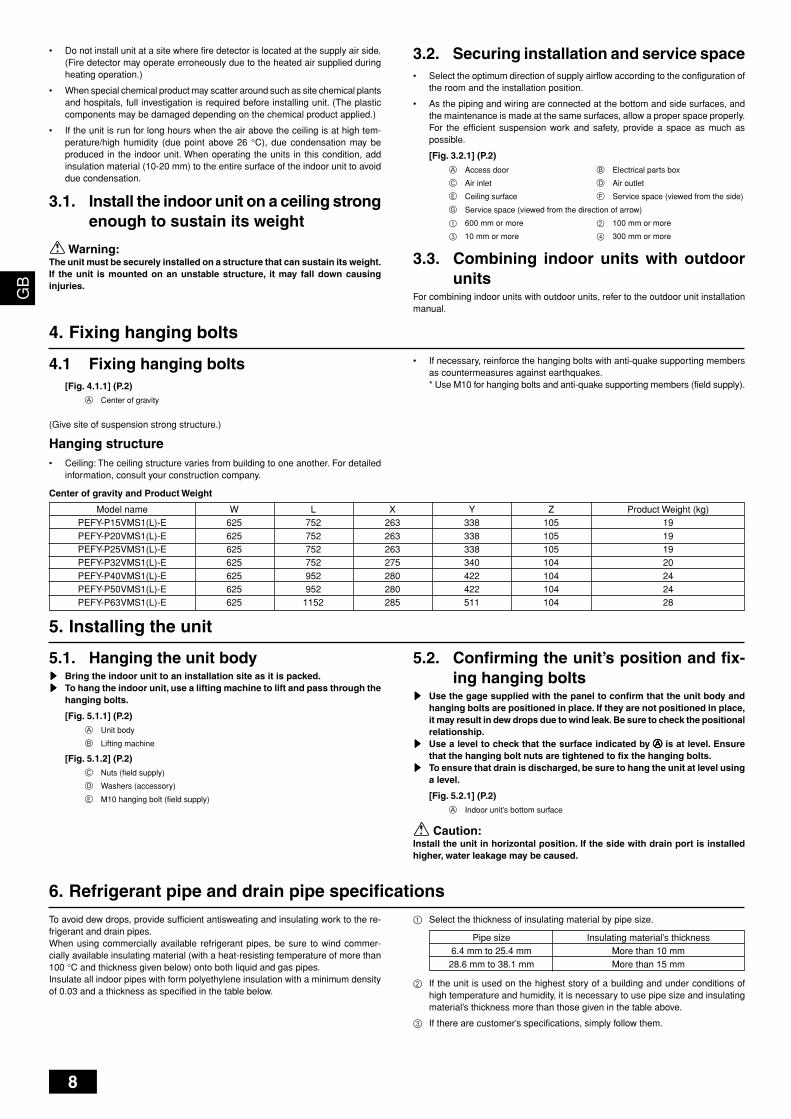
4.1 Fixing hanging bolts[Fig. 4.1.1] (P.2)
A Center of gravity
(Give site of suspension strong structure.)
Hanging structure• Ceiling: The ceiling structure varies from building to one another. For detailed
information, consult your construction company.
• Do not install unit at a site where fire detector is located at the supply air side.(Fire detector may operate erroneously due to the heated air supplied duringheating operation.)
• When special chemical product may scatter around such as site chemical plantsand hospitals, full investigation is required before installing unit. (The plasticcomponents may be damaged depending on the chemical product applied.)
• If the unit is run for long hours when the air above the ceiling is at high tem-perature/high humidity (due point above 26 °C), due condensation may beproduced in the indoor unit. When operating the units in this condition, addinsulation material (10-20 mm) to the entire surface of the indoor unit to avoiddue condensation.
3.1. Install the indoor unit on a ceiling strongenough to sustain its weight
Warning:The unit must be securely installed on a structure that can sustain its weight.If the unit is mounted on an unstable structure, it may fall down causinginjuries.
3.2. Securing installation and service space• Select the optimum direction of supply airflow according to the configuration of
the room and the installation position.
• As the piping and wiring are connected at the bottom and side surfaces, andthe maintenance is made at the same surfaces, allow a proper space properly.For the efficient suspension work and safety, provide a space as much aspossible.
[Fig. 3.2.1] (P.2)
A Access door B Electrical parts box
C Air inlet D Air outlet
E Ceiling surface F Service space (viewed from the side)
G Service space (viewed from the direction of arrow)
1 600 mm or more 2 100 mm or more
3 10 mm or more 4 300 mm or more
3.3. Combining indoor units with outdoorunits
For combining indoor units with outdoor units, refer to the outdoor unit installationmanual.
• If necessary, reinforce the hanging bolts with anti-quake supporting membersas countermeasures against earthquakes.* Use M10 for hanging bolts and anti-quake supporting members (field supply).
5. Installing the unit
5.1. Hanging the unit bodysssss Bring the indoor unit to an installation site as it is packed.sssss To hang the indoor unit, use a lifting machine to lift and pass through the
hanging bolts.
[Fig. 5.1.1] (P.2)A Unit body
B Lifting machine
[Fig. 5.1.2] (P.2)C Nuts (field supply)
D Washers (accessory)
E M10 hanging bolt (field supply)
5.2. Confirming the unit’s position and fix-ing hanging bolts
sssss Use the gage supplied with the panel to confirm that the unit body andhanging bolts are positioned in place. If they are not positioned in place,it may result in dew drops due to wind leak. Be sure to check the positionalrelationship.
sssss Use a level to check that the surface indicated by AAAAA is at level. Ensurethat the hanging bolt nuts are tightened to fix the hanging bolts.
sssss To ensure that drain is discharged, be sure to hang the unit at level usinga level.
[Fig. 5.2.1] (P.2)A Indoor unit’s bottom surface
Caution:Install the unit in horizontal position. If the side with drain port is installedhigher, water leakage may be caused.
6. Refrigerant pipe and drain pipe specifications
Model namePEFY-P15VMS1(L)-EPEFY-P20VMS1(L)-EPEFY-P25VMS1(L)-EPEFY-P32VMS1(L)-EPEFY-P40VMS1(L)-EPEFY-P50VMS1(L)-EPEFY-P63VMS1(L)-E
W625625625625625625625
L752752752752952952
1152
X263263263275280280285
Y338338338340422422511
Z105105105104104104104
Product Weight (kg)19191920242428
Center of gravity and Product Weight
To avoid dew drops, provide sufficient antisweating and insulating work to the re-frigerant and drain pipes.When using commercially available refrigerant pipes, be sure to wind commer-cially available insulating material (with a heat-resisting temperature of more than100 °C and thickness given below) onto both liquid and gas pipes.Insulate all indoor pipes with form polyethylene insulation with a minimum densityof 0.03 and a thickness as specified in the table below.
1 Select the thickness of insulating material by pipe size.
Pipe size Insulating material’s thickness6.4 mm to 25.4 mm More than 10 mm28.6 mm to 38.1 mm More than 15 mm
2 If the unit is used on the highest story of a building and under conditions ofhigh temperature and humidity, it is necessary to use pipe size and insulatingmaterial’s thickness more than those given in the table above.
3 If there are customer’s specifications, simply follow them.
KB79H130H01_en 07.5.28, 4:08 PM8
9
GB
DF
EI
NL
PG
RR
UT
RC
ZS
VH
GP
O
• Store the piping to be used during installation indoors and keep bothends of the piping sealed until just before brazing.- If dust, dirt, or water gets into the refrigerant cycle, the oil will deteriorate and
the compressor may fail.• Use Suniso 4GS or 3GS (small amount) refrigerator oil to coat the flare
and flange connection part. (For models using R22)• Use ester oil, ether oil or alkylbenzene (small amount) as the refrigerator oil
to coat flares and flange connections. (For models using R410A or R407C)- The refrigerant used in the unit is highly hygroscopic and mixes with water
and will degrade the refrigerator oil.
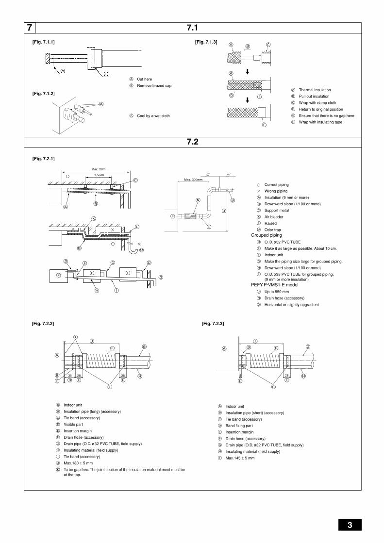
7.2. Drain piping work• Ensure that the drain piping is downward (pitch of more than 1/100) to the
outdoor (discharge) side. Do not provide any trap or irregularity on the way.
• Ensure that any cross-wise drain piping is less than 20 m (excluding the differ-ence of elevation). If the drain piping is long, provide metal braces to prevent itfrom waving. Never provide any air vent pipe. Otherwise drain may be ejected.
• Use a hard vinyl chloride pipe O.D. ø32 for drain piping.
• Ensure that collected pipes are 10 cm lower than the unit body’s drain port.
• Do not provide any odor trap at the drain discharge port.
• Put the end of the drain piping in a position where no odor is generated.
• Do not put the end of the drain piping in any drain where ionic gases are generated.
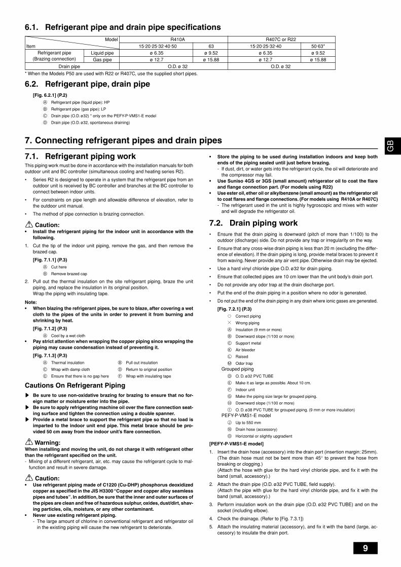
[Fig. 7.2.1] (P.3)Correct piping
Wrong piping
A Insulation (9 mm or more)
B Downward slope (1/100 or more)
C Support metal
K Air bleeder
L Raised
M Odor trapGrouped piping
D O. D. ø32 PVC TUBE
E Make it as large as possible. About 10 cm.
F Indoor unit
G Make the piping size large for grouped piping.
H Downward slope (1/100 or more)
I O. D. ø38 PVC TUBE for grouped piping. (9 mm or more insulation)PEFY-P·VMS1-E model
J Up to 550 mm
N Drain hose (accessory)
O Horizontal or slightly upgradient
[PEFY-P·VMS1-E model]
1. Insert the drain hose (accessory) into the drain port (insertion margin: 25mm).(The drain hose must not be bent more than 45° to prevent the hose frombreaking or clogging.)(Attach the hose with glue for the hard vinyl chloride pipe, and fix it with theband (small, accessory).)
2. Attach the drain pipe (O.D. ø32 PVC TUBE, field supply).(Attach the pipe with glue for the hard vinyl chloride pipe, and fix it with theband (small, accessory).)
3. Perform insulation work on the drain pipe (O.D. ø32 PVC TUBE) and on thesocket (including elbow).
4. Check the drainage. (Refer to [Fig. 7.3.1])
5. Attach the insulating material (accessory), and fix it with the band (large, ac-cessory) to insulate the drain port.
7. Connecting refrigerant pipes and drain pipes
7.1. Refrigerant piping workThis piping work must be done in accordance with the installation manuals for bothoutdoor unit and BC controller (simultaneous cooling and heating series R2).
• Series R2 is designed to operate in a system that the refrigerant pipe from anoutdoor unit is received by BC controller and branches at the BC controller toconnect between indoor units.
• For constraints on pipe length and allowable difference of elevation, refer tothe outdoor unit manual.
• The method of pipe connection is brazing connection.
Caution:• Install the refrigerant piping for the indoor unit in accordance with the
following.
1. Cut the tip of the indoor unit piping, remove the gas, and then remove thebrazed cap.
[Fig. 7.1.1] (P.3)A Cut here
B Remove brazed cap
2. Pull out the thermal insulation on the site refrigerant piping, braze the unitpiping, and replace the insulation in its original position.Wrap the piping with insulating tape.
Note:• When blazing the refrigerant pipes, be sure to blaze, after covering a wet
cloth to the pipes of the units in order to prevent it from burning andshrinking by heat.
[Fig. 7.1.2] (P.3)A Cool by a wet cloth
• Pay strict attention when wrapping the copper piping since wrapping thepiping may cause condensation instead of preventing it.
[Fig. 7.1.3] (P.3)A Thermal insulation B Pull out insulation
C Wrap with damp cloth D Return to original position
E Ensure that there is no gap here F Wrap with insulating tape
Cautions On Refrigerant Pipingsssss Be sure to use non-oxidative brazing for brazing to ensure that no for-
eign matter or moisture enter into the pipe.sssss Be sure to apply refrigerating machine oil over the flare connection seat-
ing surface and tighten the connection using a double spanner.sssss Provide a metal brace to support the refrigerant pipe so that no load is
imparted to the indoor unit end pipe. This metal brace should be pro-vided 50 cm away from the indoor unit’s flare connection.
Warning:When installing and moving the unit, do not charge it with refrigerant otherthan the refrigerant specified on the unit.- Mixing of a different refrigerant, air, etc. may cause the refrigerant cycle to mal-
function and result in severe damage.
Caution:• Use refrigerant piping made of C1220 (Cu-DHP) phosphorus deoxidized
copper as specified in the JIS H3300 “Copper and copper alloy seamlesspipes and tubes”. In addition, be sure that the inner and outer surfaces ofthe pipes are clean and free of hazardous sulphur, oxides, dust/dirt, shav-ing particles, oils, moisture, or any other contaminant.
• Never use existing refrigerant piping.- The large amount of chlorine in conventional refrigerant and refrigerator oil
in the existing piping will cause the new refrigerant to deteriorate.
6.1. Refrigerant pipe and drain pipe specifications
Refrigerant pipe(Brazing connection)
Model R410A R407C or R22Item 15·20·25·32·40·50 63 15·20·25·32·40 50·63*
Liquid pipe ø 6.35 ø 9.52 ø 6.35 ø 9.52Gas pipe ø 12.7 ø 15.88 ø 12.7 ø 15.88
Drain pipe O.D. ø 32 O.D. ø 32
6.2. Refrigerant pipe, drain pipe[Fig. 6.2.1] (P.2)
A Refrigerant pipe (liquid pipe): HP
B Refrigerant pipe (gas pipe): LP
C Drain pipe (O.D. ø32) * only on the PEFY-P·VMS1-E model
D Drain pipe (O.D. ø32, spontaneous draining)
* When the Models P50 are used with R22 or R407C, use the supplied short pipes.
KB79H130H01_en 07.4.25, 4:33 PM9
10
GB
DF
EI
NL
PG
RR
UT
RC
ZS
VH
GP
O
9. Electrical wiring
Precautions on electrical wiring
Warning:Electrical work should be done by qualified electrical engineers in accord-ance with “Engineering Standards For Electrical Installation” and suppliedinstallation manuals. Special circuits should also be used. If the power cir-cuit lacks capacity or has an installation failure, it may cause a risk of elec-tric shock or fire.
1. Be sure to install an earth leakage breaker to the power.
2. Install the unit to prevent that any of the control circuit cables (remote control-ler, transmission cables) is brought in direct contact with the power cable out-side the unit.
3. Ensure that there is no slack on all wire connections.
4. Some cables (power, remote controller, transmission cables) above the ceilingmay be bitten by mouses. Use as many metal pipes as possible to insert thecables into them for protection.
5. Never connect the power cable to leads for the transmission cables. Otherwisethe cables would be broken.
6. Be sure to connect control cables to the indoor unit, remote controller, and theoutdoor unit.
7. Put the unit to the ground on the outdoor unit side.
8. Select control cables from the conditions given in page 11.
Caution:Be sure to put the unit to the ground on the outdoor unit side. Do not con-nect the earth cable to any gas pipe, water pipe, lightening rod, or telephoneearth cable. Incomplete grounding may cause a risk of electric shock.
Types of control cables1. Wiring transmission cables
• Types of transmission cables
Design wiring in accordance with the following table <Table 1>.
• Cable diameter
More than 1.25 mm2
8. Duct work• When connecting ducts, insert a canvas duct between the main body and the
duct.
• Use non-combustible duct components.
• Install sufficient thermal insulation to prevent condensation forming on outletduct flanges and outlet ducts.
Caution:• Keep the distance between the inlet grille and the fan over 850 mm.
If it is less than 850 mm, install a safety guard not to touch the fan.
[Fig. 8.0.1] (P.4)A Air inlet B Air outlet
C Access door D Ceiling surface
E Canvas duct F Air filter
G Inlet grille
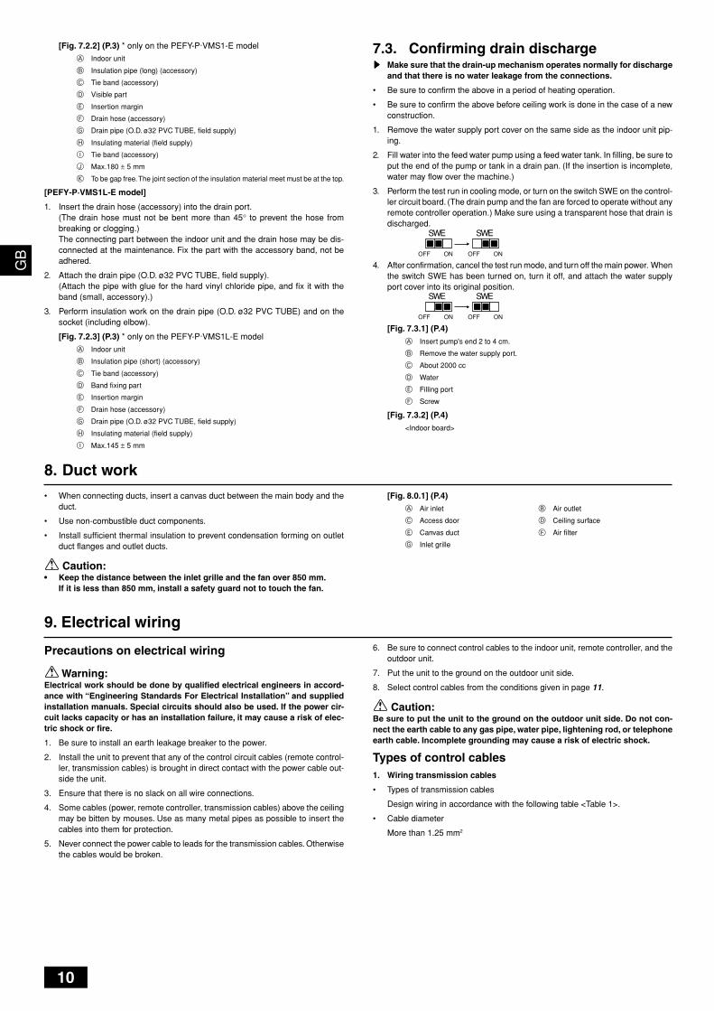
7.3. Confirming drain dischargesssss Make sure that the drain-up mechanism operates normally for discharge
and that there is no water leakage from the connections.
• Be sure to confirm the above in a period of heating operation.
• Be sure to confirm the above before ceiling work is done in the case of a newconstruction.
1. Remove the water supply port cover on the same side as the indoor unit pip-ing.
2. Fill water into the feed water pump using a feed water tank. In filling, be sure toput the end of the pump or tank in a drain pan. (If the insertion is incomplete,water may flow over the machine.)
3. Perform the test run in cooling mode, or turn on the switch SWE on the control-ler circuit board. (The drain pump and the fan are forced to operate without anyremote controller operation.) Make sure using a transparent hose that drain isdischarged.
4. After confirmation, cancel the test run mode, and turn off the main power. Whenthe switch SWE has been turned on, turn it off, and attach the water supplyport cover into its original position.
[Fig. 7.3.1] (P.4)
A Insert pump's end 2 to 4 cm.
B Remove the water supply port.
C About 2000 cc
D Water
E Filling port
F Screw
[Fig. 7.3.2] (P.4)
<Indoor board>
[Fig. 7.2.2] (P.3) * only on the PEFY-P·VMS1-E model
A Indoor unit
B Insulation pipe (long) (accessory)
C Tie band (accessory)
D Visible part
E Insertion margin
F Drain hose (accessory)
G Drain pipe (O.D. ø32 PVC TUBE, field supply)
H Insulating material (field supply)
I Tie band (accessory)
J Max.180 ± 5 mm
K To be gap free. The joint section of the insulation material meet must be at the top.
[PEFY-P·VMS1L-E model]
1. Insert the drain hose (accessory) into the drain port.(The drain hose must not be bent more than 45° to prevent the hose frombreaking or clogging.)The connecting part between the indoor unit and the drain hose may be dis-connected at the maintenance. Fix the part with the accessory band, not beadhered.
2. Attach the drain pipe (O.D. ø32 PVC TUBE, field supply).(Attach the pipe with glue for the hard vinyl chloride pipe, and fix it with theband (small, accessory).)
3. Perform insulation work on the drain pipe (O.D. ø32 PVC TUBE) and on thesocket (including elbow).
[Fig. 7.2.3] (P.3) * only on the PEFY-P·VMS1L-E model
A Indoor unit
B Insulation pipe (short) (accessory)
C Tie band (accessory)
D Band fixing part
E Insertion margin
F Drain hose (accessory)
G Drain pipe (O.D. ø32 PVC TUBE, field supply)
H Insulating material (field supply)
I Max.145 ± 5 mm
SWE SWE
OFF ON OFF ON
SWE SWE
OFF ON OFF ON
KB79H130H01_en 07.4.25, 4:33 PM10
11
GB
DF
EI
NL
PG
RR
UT
RC
ZS
VH
GP
O
Caution:Install wiring so that it is not tight and under tension. Wiring under tensionmay break, or overheat and burn.
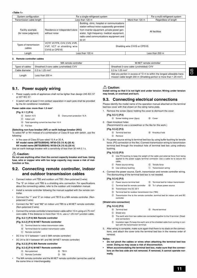
9.3. Connecting electrical connectionsPlease identify the model name of the operation manual attached on the terminalbed box cover with that shown on the rating name plate.
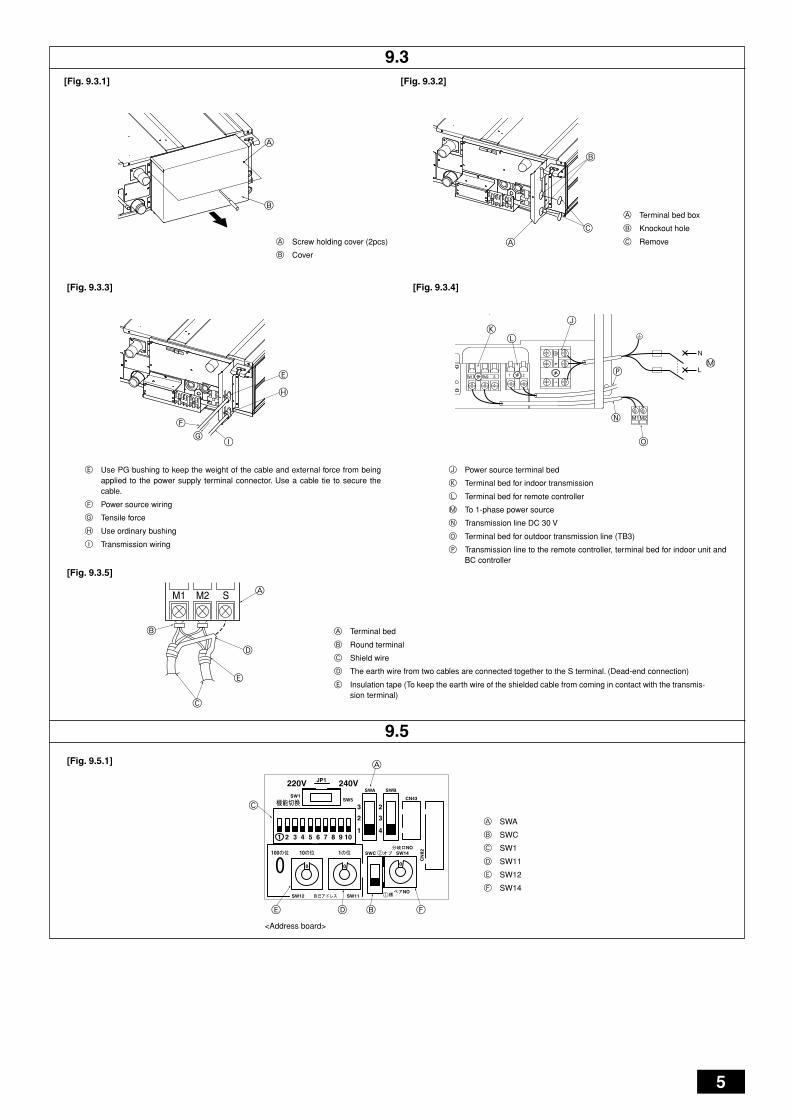
1. Remove the screw (2pcs) holding the cover to dismount the cover.
[Fig. 9.3.1] (P.5)A Screw holding cover (2pcs) B Cover
2. Open knockout holes(Recommend to use a screwdriver or the like for this work.)
[Fig. 9.3.2] (P.5)
A Terminal bed box B Knockout hole
C Remove
3. Fix power source wiring to terminal bed box by using buffer bushing for tensileforce. (PG connection or the like.) Connect transmission wiring to transmissionterminal bed through the knockout hole of terminal bed box using ordinarybushing.
[Fig. 9.3.3] (P.5)E Use PG bushing to keep the weight of the cable and external force from being
applied to the power supply terminal connector. Use a cable tie to secure thecable.
F Power source wiring G Tensile force
H Use ordinary bushing I Transmission wiring
4. Connect the power source, Earth, transmission and remote controller wiring.The dismounting of the terminal bed box is not needed.
[Fig. 9.3.4] (P.5)
J Power source terminal bed K Terminal bed for indoor transmission
L Terminal bed for remote controller M To 1-phase power source
N Transmission line DC 30 V
O Terminal bed for outdoor transmission line (TB3)
P Transmission line to the remote controller, terminal bed for indoor unit and BCcontroller
[Shield wire connection]
[Fig. 9.3.5] (P.5)A Terminal bed B Round terminal
C Shield wire
D The earth wire from two cables are connected together to the S terminal. (Dead-end connection)
E Insulation tape (To keep the earth wire of the shielded cable from coming in con-tact with the transmission terminal)
5. After wiring is complete, make sure again that there is no slack on the connec-tions, and attach the cover onto the terminal bed box in the reverse order ofremoval.
Notes:• Do not pinch the cables or wires when attaching the terminal bed box
cover. Doing so may cause a risk of disconnection.• When accommodating the terminal bed box, make sure that the connec-
tors on the box side are not removed. If removed, it cannot operate nor-mally.
9.1. Power supply wiring• Power supply cords of appliances shall not be lighter than design 245 IEC 57
or 227 IEC 57.
• A switch with at least 3 mm contact separation in each pole shall be providedby the Air conditioner installation.
Power cable size: more than 1.5 mm2
[Fig. 9.1.1] (P.4)
A Switch 16 A B Overcurrent protection 16 A
C Indoor unit
D Total operating current be less than 16 A
E Pull box
[Selecting non-fuse breaker (NF) or earth leakage breaker (NV)]To select NF or NV instead of a combination of Class B fuse with switch, use thefollowing:
• In the case of Class B fuse rated 15 A or 20 A,NF model name (MITSUBISHI): NF30-CS (15 A) (20 A)NV model name (MITSUBISHI): NV30-CA (15 A) (20 A)
Use an earth leakage breaker with a sensitivity of less than 30 mA 0.1 s.
Caution:Do not use anything other than the correct capacity breaker and fuse. Usingfuse, wire or copper wire with too large capacity may cause a risk of mal-function or fire.
9.2. Connecting remote controller, indoorand outdoor transmission cables
• Connect indoor unit TB5 and outdoor unit TB3. (Non-polarized 2-wire)
The “S” on indoor unit TB5 is a shielding wire connection. For specificationsabout the connecting cables, refer to the outdoor unit installation manual.
• Install a remote controller following the manual supplied with the remote con-troller.
• Connect the “1” and “2” on indoor unit TB15 to a MA remote controller. (Non-polarized 2-wire)
• Connect the “M1” and “M2” on indoor unit TB5 to a M-NET remote controller.(Non-polarized 2-wire)
• Connect the remote controller’s transmission cable within 10 m using a 0.75 mm2
core cable. If the distance is more than 10 m, use a 1.25 mm2 junction cable.
[Fig. 9.2.1] (P.4) MA Remote controller
[Fig. 9.2.2] (P.4) M-NET Remote controllerA Terminal block for indoor transmission cable
B Terminal block for outdoor transmission cable
C Remote controller
• DC 9 to 13 V between 1 and 2 (MA remote controller)
• DC 24 to 30 V between M1 and M2 (M-NET remote controller)
[Fig. 9.2.3] (P.4) MA Remote controller
[Fig. 9.2.4] (P.4) M-NET Remote controllerA Non-polarized B TB15
C Remote Controller D TB5
• The MA remote controller and the M-NET remote controller cannot be used atthe same time or interchangeably.
2. Remote controller cables
Types of cables
Cable diameter
Length
MA remote controller
Sheathed 2-core cable (unshielded) CVV
0.3 to 1.25 mm2
Less than 200 m
M-NET remote controller
Sheathed 2-core cable (unshielded) CVV
0.3 to 1.25 mm2
Add any portion in excess of 10 m to within the longest allowable trans-mission cable length 200 m (Shielding portion is more than 1.25 mm2)
<Table 1>
System configuration For a single-refrigerant system For a multi-refrigerant systemTransmission cable length Less than 120 m More than 120 m Regardless of length
Facility example(for noise judgment)
Types of transmissioncables
Residence or independent storewithout noise
VCTF, VCTFK, CVV, CVS, VVR,VVF, VCT or shielding wireCVVS or CPEVS
Building, clinic, hospital or communicationsstation without noise supposedly generatedfrom inverter equipment, private power gen-erator, high-frequency medical equipment,radio-used communications equipment andso on
All facilities
Shielding wire CVVS or CPEVS
Length Less than 120 m Less than 200 m
KB79H130H01_en 07.4.25, 4:33 PM11
12
GB
DF
EI
NL
PG
RR
UT
RC
ZS
VH
GP
O
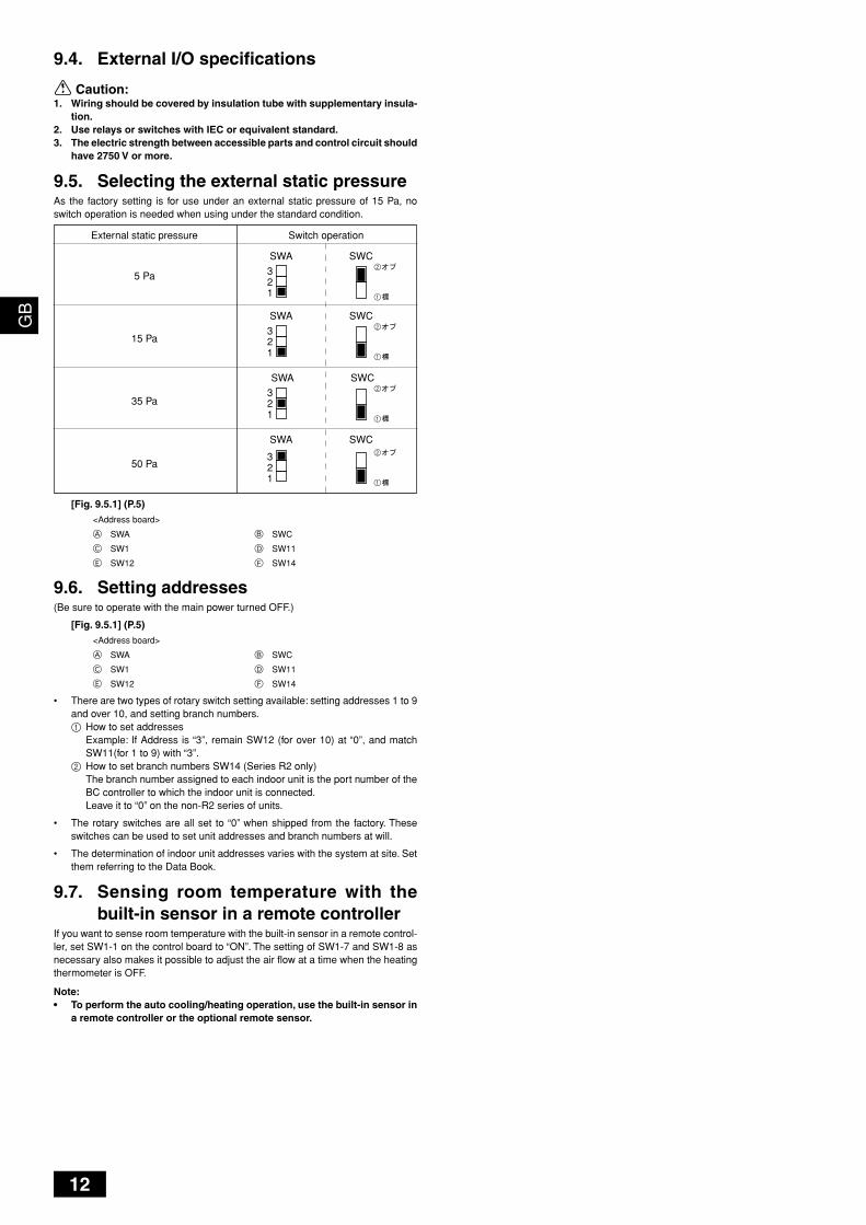
[Fig. 9.5.1] (P.5)<Address board>
A SWA B SWC
C SW1 D SW11
E SW12 F SW14
9.6. Setting addresses(Be sure to operate with the main power turned OFF.)
[Fig. 9.5.1] (P.5)<Address board>
A SWA B SWC
C SW1 D SW11
E SW12 F SW14
• There are two types of rotary switch setting available: setting addresses 1 to 9and over 10, and setting branch numbers.1 How to set addresses
Example: If Address is “3”, remain SW12 (for over 10) at “0”, and matchSW11(for 1 to 9) with “3”.
2 How to set branch numbers SW14 (Series R2 only)The branch number assigned to each indoor unit is the port number of theBC controller to which the indoor unit is connected.Leave it to “0” on the non-R2 series of units.
• The rotary switches are all set to “0” when shipped from the factory. Theseswitches can be used to set unit addresses and branch numbers at will.
• The determination of indoor unit addresses varies with the system at site. Setthem referring to the Data Book.
9.7. Sensing room temperature with thebuilt-in sensor in a remote controller
If you want to sense room temperature with the built-in sensor in a remote control-ler, set SW1-1 on the control board to “ON”. The setting of SW1-7 and SW1-8 asnecessary also makes it possible to adjust the air flow at a time when the heatingthermometer is OFF.
Note:• To perform the auto cooling/heating operation, use the built-in sensor in
a remote controller or the optional remote sensor.
9.4. External I/O specifications
Caution:1. Wiring should be covered by insulation tube with supplementary insula-
tion.2. Use relays or switches with IEC or equivalent standard.3. The electric strength between accessible parts and control circuit should
have 2750 V or more.
9.5. Selecting the external static pressureAs the factory setting is for use under an external static pressure of 15 Pa, noswitch operation is needed when using under the standard condition.
External static pressure Switch operation
5 Pa
15 Pa
35 Pa
50 Pa
321
SWA
321
SWA
321
SWA
321
SWA
SWC
1
2
SWC
1
2
SWC
1
2
SWC
1
2
KB79H130H01_en 07.4.25, 6:12 PM12
KB79H130H01
HEAD OFFICE: TOKYO BLDG., 2-7-3, MARUNOUCHI, CHIYODA-KU, TOKYO 100-8310, JAPAN
Please be sure to put the contact address/telephone number onthis manual before handing it to the customer.
The product at hand isbased on the followingEU regulations:
• Low Voltage Directive 2006/95/EC• Electromagnetic Compatibility Directive 89/
336/EEC, 2004/108/EC
This product is designed and intended for use in the residential, commer-cial and light-industrial environment.
KB79H130H01_cv_16lang.p65 07.7.4, 3:49 PM2