
Allgemeine Informationen General information Informations ... tecnicos.pdf · Gewindetabellen und...
20
291 i Allgemeine Informationen General information Informations générales Informazioni generali Gewindebohrer / Gewindeformer Taps / cold forming taps Tarauds / tarauds à refouler Maschi / maschi a rullare 292 - 302 Formelsammlung Formulae Formules de calcul Raccolta di formule 332 - 333 Schneideisen Dies Filières Filiere 303 - 305 Gewindetabellen und Toleranzen Thread tables and tolerances Tableaux de filets et tolérances Tabelle di filetti e tolleranze 334 - 350 Gewindelehren Thread gauges Calibres de contrôle Calibri filettati 306 - 315 Internationaler Werkstoffvergleich International comparison of materials Comparatif matieres Confronto internazionale dei materiali 352 - 367 Aufnahmen und Zubehör Tap holders and accessories Mandrins de taraudage et accessoires Mandrini ed accessori 316 - 331 Lieferbedingungen für Präzisionswerkzeuge (Inlandsbestellungen) Terms of delivery for precision tools (for domestic sales) 368 - 369
Transcript of Allgemeine Informationen General information Informations ... tecnicos.pdf · Gewindetabellen und...

291 i
Allgemeine Informationen General information
Informations généralesInformazioni generali
Gewindebohrer / GewindeformerTaps / cold forming tapsTarauds / tarauds à refoulerMaschi / maschi a rullare
292 - 302
FormelsammlungFormulae Formules de calcul Raccolta di formule
332 - 333
SchneideisenDiesFilièresFiliere
303 - 305
Gewindetabellen und Toleranzen Thread tables and tolerancesTableaux de fi lets et tolérancesTabelle di fi letti e tolleranze
334 - 350
GewindelehrenThread gaugesCalibres de contrôleCalibri fi lettati
306 - 315
Internationaler WerkstoffvergleichInternational comparison of materials Comparatif matieres Confronto internazionale dei materiali
352 - 367
Aufnahmen und ZubehörTap holders and accessoriesMandrins de taraudage et accessoiresMandrini ed accessori
316 - 331
Lieferbedingungen für Präzisionswerkzeuge (Inlandsbestellungen)Terms of delivery for precision tools (for domestic sales)
368 - 369
292i
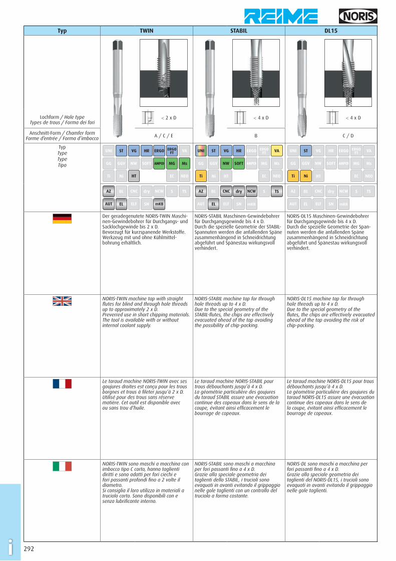
Typ TWIN STABIL DL15
Lochform / Hole type Types de trous / Forma dei fori
< 2 x D < 4 x D < 4 x D
Anschnitt-Form / Chamfer formForme d’entrée / Forma d’imbocco A / C / E B C / D
Typ TypeTypeTipo
UNI ST VG HR ERGO ERGOFT VA
GG GGV NW SOFT AMPCO MG Ms
Ti Ni HT EC NEO
UNI ST VG HR ERGO ERGOFT VA
GG GGV NW SOFT AMPCO MG Ms
Ti Ni HT EC NEO
UNI ST VG HR ERGO ERGOFT VA
GG GGV NW SOFT AMPCO MG Ms
Ti Ni HT EC NEO
AZ BL CNC dry NCW S TS
AUT EL ELF SN mKB
AZ BL CNC dry NCW S TS
AUT EL ELF SN mKB
AZ BL CNC dry NCW S TS
AUT EL ELF SN mKB
Der geradegenutete NORIS-TWIN Maschi-nen-Gewindebohrer für Durchgangs- und Sacklochgewinde bis 2 x D. Bevorzugt für kurzspanende Werkstoffe. Werkzeug mit und ohne Kühlmittel-bohrung erhältlich.
NORIS-STABIL Maschinen-Gewindebohrer für Durchgangsgewinde bis 4 x D. Durch die spezielle Geometrie der STABIL-Span nuten werden die anfallenden Späne zusammenhängend in Schneidrichtung abgeführt und Spänestau wirkungsvoll verhindert.
NORIS-DL15 Maschinen-Gewindebohrer für Durchgangsgewinde bis 4 x D. Durch die spezielle Geometrie der Span-nuten werden die anfallenden Späne zusammenhängend in Schneidrichtung abgeführt und Spänestau wirkungsvoll verhindert.
NORIS-TWIN machine tap with straight fl utes for blind and through hole threads up to approximately 2 x D. Preverred use in short chipping materials. The tool is available with or without internal coolant supply.
NORIS-STABIL machine tap for through hole threads up to 4 x D. Due to the special geometry of the STABIL-fl utes, the chips are effectively evacuated ahead of the tap avoiding the possibility of chip-packing.
NORIS-DL15 machine tap for through hole threads up to 4 x D. Due to the special geometry of the fl utes, the chips are effectively evacuated ahead of the tap avoiding the risk of chip-packing.
Le taraud machine NORIS-TWIN avec ses goujures droites est conçu pour les trous borgnes et trous à fi leter jusqu‘à 2 x D. Utilisé pour des trous sans réserve matière. Cet outil est disponible avec ou sans trou d‘huile.
Le taraud machine NORIS-STABIL pour trous débouchants jusqu’à 4 x D. La géométrie particulière des goujures du taraud STABIL assure une évacuation continue des copeaux dans le sens de la coupe, évitant ainsi effi cacement le bourrage de copeaux.
Le taraud machine NORIS-DL15 pour trous débouchants jusqu’à 4 x D. La géométrie particulière des goujures du taraud NORIS-DL15 assure une évacuation continue des copeaux dans le sens de la coupe, évitant ainsi effi cacement le bourrage de copeaux.
NORIS-TWIN sono maschi a macchina con imbocco tipo C corto, hanno taglienti diritti e sono adatti per fori ciechi e fori passanti profondi fi no a 2 volte il diametro. Si consiglia il loro utilizzo in materiali a truciolo corto. Sono disponibili con e senza lubrifi cante interno.
NORIS-STABIL sono maschi a macchina per fori passanti fi no a 4 x D. Grazie alla speciale geometria dei taglienti dello STABIL, i trucioli sono evaquati in avanti evitando il grippaggio nelle gole taglienti con un controllo del truciolo a forma costante.
NORIS-DL sono maschi a macchina per fori passanti fi no a 4 x D. Grazie alla speciale geometria dei taglienti del NORIS-DL15, i trucioli sono evaquati in avanti evitando il grippaggio nelle gole taglienti.
293 i
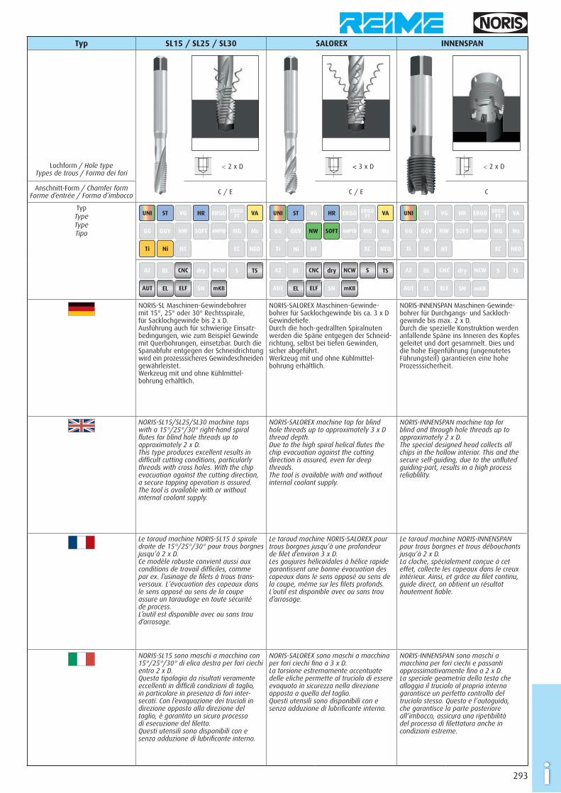
Typ SL15 / SL25 / SL30 SALOREX INNENSPAN
Lochform / Hole type Types de trous / Forma dei fori
< 2 x D < 3 x D < 2 x D
Anschnitt-Form / Chamfer formForme d’entrée / Forma d’imbocco C / E C / E C
Typ TypeTypeTipo
UNI ST VG HR ERGO ERGOFT VA
GG GGV NW SOFT AMPCO MG Ms
Ti Ni HT EC NEO
UNI ST VG HR ERGO ERGOFT VA
GG GGV NW SOFT AMPCO MG Ms
Ti Ni HT EC NEO
UNI ST VG HR ERGO ERGOFT VA
GG GGV NW SOFT AMPCO MG Ms
Ti Ni HT EC NEO
AZ BL CNC dry NCW S TS
AUT EL ELF SN mKB
AZ BL CNC dry NCW S TS
AUT EL ELF SN mKB
AZ BL CNC dry NCW S TS
AUT EL ELF SN mKB
NORIS-SL Maschinen-Gewindebohrer mit 15°, 25° oder 30° Rechtsspirale, für Sacklochgewinde bis 2 x D. Ausführung auch für schwierige Einsatz-bedingungen, wie zum Beispiel Gewinde mit Querbohrungen, einsetzbar. Durch die Spanabfuhr entgegen der Schneidrichtung wird ein prozesssicheres Gewindeschneiden gewährleistet. Werkzeug mit und ohne Kühlmittel-bohrung erhältlich.
NORIS-SALOREX Maschinen-Gewinde-bohrer für Sacklochgewinde bis ca. 3 x D Gewindetiefe. Durch die hoch-gedrallten Spiralnuten werden die Späne entgegen der Schneid-richtung, selbst bei tiefen Gewinden, sicher abgeführt. Werkzeug mit und ohne Kühlmittel-bohrung erhältlich.
NORIS-INNENSPAN Maschinen-Gewinde-bohrer für Durchgangs- und Sackloch-gewinde bis max. 2 x D. Durch die spezielle Konstruktion werden anfallende Späne ins Inneren des Kopfes geleitet und dort gesammelt. Dies und die hohe Eigenführung (ungenutetes Führungsteil) garantieren eine hohe Prozesssicherheit.
NORIS-SL15/SL25/SL30 machine taps with a 15°/25°/30° right-hand spiral fl utes for blind hole threads up to approximately 2 x D. This type produces excellent results in diffi cult cutting conditions, particularly threads with cross holes. With the chip evacuation against the cutting direction, a secure tapping operation is assured. The tool is available with or without internal coolant supply.
NORIS-SALOREX machine tap for blind hole threads up to approximately 3 x D thread depth. Due to the high spiral helical fl utes the chip evacuation against the cutting direction is assured, even for deep threads. The tool is available with and without internal coolant supply.
NORIS-INNENSPAN machine tap for blind and through hole threads up to approximately 2 x D. The special designed head collects all chips in the hollow interior. This and the secure self-guiding, due to the unfl uted guiding-part, results in a high process reliablility.
Le taraud machine NORIS-SL15 à spirale droite de 15°/25°/30° pour trous borgnes jusqu’à 2 x D. Ce modèle robuste convient aussi aux conditions de travail diffi ciles, comme par ex. l’usinage de fi lets à trous trans-versaux. L’évacuation des copeaux dans le sens opposé au sens de la coupe assure un taraudage en toute sécurité de process. L’outil est disponible avec ou sans trou d’arrosage.
Le taraud machine NORIS-SALOREX pour trous borgnes jusqu’à une profondeur de fi let d’environ 3 x D. Les goujures hélicoïdales à hélice rapide garantissent une bonne évacuation des copeaux dans le sens opposé au sens de la coupe, même sur les fi lets profonds. L’outil est disponible avec ou sans trou d’arrosage.
Le taraud machine NORIS-INNENSPAN pour trous borgnes et trous débouchants jusqu‘à 2 x D. La cloche, spécialement conçue à cet effet, collecte les copeaux dans le creux intérieur. Ainsi, et grâce au fi let continu, guide direct, on obtient un résultat hautement fi able.
NORIS-SL15 sono maschi a macchina con 15°/25°/30° di elica destra per fori ciechi entro 2 x D. Questa tipologia da risultati veramente eccellenti in diffi cili condizioni di taglio, in particolare in presenza di fori inter-secati. Con l’evaquazione dei trucioli in direzione opposta alla direzione del taglio, è garantito un sicuro processo di esecuzione del fi letto. Questi utensili sono disponibili con e senza adduzione di lubrifi cante interno.
NORIS-SALOREX sono maschi a macchina per fori ciechi fi no a 3 x D. La torsione estremamente accentuate delle eliche permette al truciolo di essere evaquato in sicurezza nella direzione opposta a quella del taglio. Questi utensili sono disponibili con e senza adduzione di lubrifi cante interno.
NORIS-INNENSPAN sono maschi a macchina per fori ciechi e passanti approssimativamente fi no a 2 x D. La speciale geometria della testa che alloggia il truciolo al proprio interno garantisce un perfetto controllo del truciolo stesso. Questo e l‘autoguida, che garantisce la parte posteriore all‘imbocco, assicura una ripetibilità del processo di fi lettatura anche in condizioni estreme.
294i
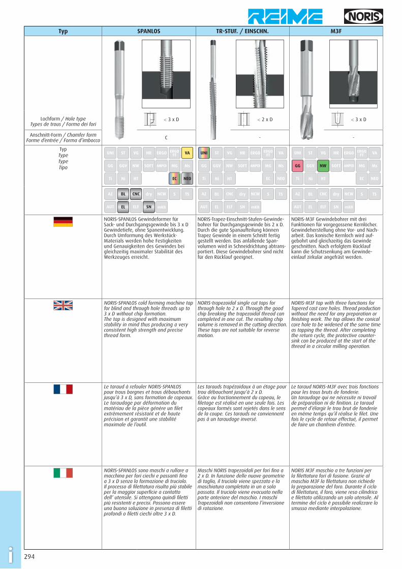
Typ SPANLOS TR-STUF. / EINSCHN. M3F
Lochform / Hole type Types de trous / Forma dei fori
< 3 x D < 2 x D < 3 x D
Anschnitt-Form / Chamfer formForme d’entrée / Forma d’imbocco C - -
Typ TypeTypeTipo
UNI ST VG HR ERGO ERGOFT VA
GG GGV NW SOFT AMPCO MG Ms
Ti Ni HT EC NEO
UNI ST VG HR ERGO ERGOFT VA
GG GGV NW SOFT AMPCO MG Ms
Ti Ni HT EC NEO
UNI ST VG HR ERGO ERGOFT VA
GG GGV NW SOFT AMPCO MG Ms
Ti Ni HT EC NEO
AZ BL CNC dry NCW S TS
AUT EL ELF SN mKB
AZ BL CNC dry NCW S TS
AUT EL ELF SN mKB
AZ BL CNC dry NCW S TS
AUT EL ELF SN mKB
NORIS-SPANLOS Gewindeformer für Sack- und Durchgangsgewinde bis 3 x D Gewindetiefe, ohne Spanentwicklung. Durch Umformung des Werkstück- Materials werden hohe Festigkeiten und Genauigkeiten des Gewindes bei gleichzeitig maximaler Stabilität des Werkzeuges erreicht.
NORIS-Trapez-Einschnitt-Stufen-Gewinde-bohrer für Durchgangsgewinde bis 2 x D. Durch die gute Spanaufteilung können Trapez Gewinde in einem Schnitt fertig gestellt werden. Das anfallende Span-volumen wird in Schneidrichtung abtrans-portiert. Diese Gewindebohrer sind nicht für den Rücklauf geeignet.
NORIS-M3F Gewindebohrer mit drei Funktionen für vorgegossene Kernlöcher. Gewindeherstellung ohne Vor- und Nach-arbeit. Das konische Kernloch wird auf-gebohrt und gleichzeitig das Gewinde geschnitten. Nach erfolgtem Rücklauf kann die Schutzsenkung am Gewinde-einlauf zirkular angefräst werden.
NORIS-SPANLOS cold forming machine tap for blind and through hole threads up to 3 x D without chip formation. The tap is designed with maximum stability in mind thus producing a very consistent high strength and precise thread form.
NORIS-trapezoidal single cut taps for through hole to 2 x D. Through the good chip breaking the trapezoidal thread can completed in one cut. The resulting chip volume is removed in the cutting direction. These taps are not suitable for reverse motion.
NORIS-M3F tap with three functions for Tapered cast core holes. Thread production without the need for any preparation or fi nishing work. The tap allows the conical core hole to be widened at the same time as tapping the thread. After completing the return cycle, the protective counter-sink can be produced at the start of the thread in a circular milling operation.
Le taraud à refouler NORIS-SPANLOS pour trous borgnes et trous débouchants jusqu’à 3 x D, sans formation de copeaux. Le taraudage par déformation du matériau de la pièce génère un fi let extrêmement résistant et de haute précision et garantit une stabilité maximale de l’outil.
Les tarauds trapézoïdaux à un étage pour trou débouchant jusqu’à 2 x D. Grâce au fractionnement du copeau, le fi letage est réalisé en une seule fois. Les copeaux formés sont rejetés dans le sens de la coupe. Ces tarauds ne conviennent pas à un taraudage inversé.
Le taraud NORIS-M3F avec trois fonctions pour les trous bruts de fonderie. Un taraudage qui ne nécessite ni travail de préparation ni de fi nition. Le taraud permet d’élargir le trou brut de fonderie en même temps qu’il réalise le fi let. Une fois le cycle de retour effectué, il permet de faire un chanfrein d’entrée.
NORIS-SPANLOS sono maschi a rullare a macchina per fori ciechi e passanti fi no a 3 x D senza la formazione di truciolo. Il processo di fi lettatura risulta più stabile per la maggior superfi cie a contatto dell‘ utensile. Si ottengono quindi fi letti più resistenti e precisi. Possono essere una buona soluzione in presenza di fi letti profondi o fi letti ciechi oltre 3 x D.
Maschi NORIS trapezoidali per fori fi no a 2 x D. In funzione delle nuove geometrie di taglio, il truciolo viene spezzato e la maschiatura completata in un a sola passata. Il truciolo viene evacuato nella parte anteriore del maschio. I maschi Trapezoidali non consentono l’inversione di rotazione.
NORIS M3F maschio a tre funzioni per la fi lettatura fori di fusione. Grazie al maschio M3F la fi lettatura non richiede la preparazione del foro. Durante il ciclo di fi lettatura, il foro, viene reso cilindrico e fi lettato utilizzando un solo utensile. Al termine del ciclo è possibile realizzare lo smusso mediante interpolazione.
295 i
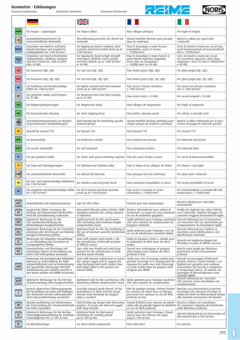
AMPCO Für Ampco - Legierungen For Ampco alloys Pour alliages d'Ampco Per leghe di Ampco
EC Gewindeformergeometrie für unterschiedlichste Werkstoffe
Threadforming geometry for almost all materials
Taraud-machine formeur pour presque tous les matériaux
Maschi a rullare per quasi tutti i materiali
ERGOSchneiden von Hand in rostfreien, hitzebeständigen und vergüteten Stahlqualitäten bis 1100 N/mm2
For tapping by hand in stainless, heat resistant and heat-treated steels up to 1100 N/mm2
Pour le taraudage à main d'aciers inoxydables, aciers à revenu < 1100N/mm2
Serie di maschi a mano per acciai inox, acciai termoresistenti ed acciai bonifi cati fi no a 1100N/mm2
ERGOFT
Schneiden von Hand in hochfesten Stahlqualitäten, Wolfram, Hartguss und Ferro-Titanit bis 1400 N/mm2 oder 44 HRc
For tapping by hand in high strength steel types, Wolfram, hard castings and ferro-titanite up to 1400 N/mm2 or 44 HRc
Pour le taraudage à main d'aciers à grand dureté supérieur, tungstène, aciers durs au manganèse < 1400N/mm2 ou 44 HRc
Serie di maschi a mano per acciai con resistenza superiore, ghisa dura, tungsteno e ferro TIC fi no a 1400N/mm2 o 44 HRc
GG Für Gusseisen (GJL, GJS) For cast iron (GJL, GJS) Pour fontes grises (GJL, GJS) Per ghisa grigia (GJL, GJS)
GGV Für Gusseisen (GJL, GJS, GJV) For cast iron (GJL, GJS, GJV) Pour fontes grises (GJL, GJS, GJV) Per ghisa grigia (GJL, GJS, GJV)
HR Für hochfeste und hitzebeständige Stähle bis 1400 N/mm2
For highly resistant and heat resistant steels up to 1400 N/mm2
Pour aciers à haute résistance ≤ 1400 N/mm2
Per acciai con elevata resistanza fi no a 1400 N/mm2
HT Für gehärtete Stähle und Hartguss bis 55 HRc
For hardened steel and hard castings up to 55 HRc Pour aciers traits ≤ 55 HRc Per acciai temprati ≤ 55 HRc
MG Für Magnesiumlegierungen For Magnesium alloys Pour alliages de magnésium Per leghe di magnesio
Ms Für kurzspanendes Messing For short chipping brass Pour laiton, copeaux courts Per ottone, a truciolo corto
NEO Gewindeformergeometrie zur Bearbei-tung bestimmter Werkstoffgruppen
Cold forming tap for machining specifi c material groups
Taraud-machine formeur optimisés pour chaque groupe de matières spécifi que
Maschi a rullare ottimizzati per la lavo-razione di gruppi di materiali specifi ci
Ni Speziell für Inconel 718 For Inconel 718 Pour Inconel 718 Per Inconel 718
NW Für Buntmetalle For nonferrous metals Pour métaux non ferreux Per materiali non ferrosi
SOFT Für weiche Werkstoffe For soft materials Pour matériaux tendres Per materiali dolci
ST Für gut spanbare Stähle For steels with good machining capacity Pour les aciers faciles à usiner Per acciai di buona lavorabilità
Ti Für Titan und Titanlegierungen For Titanium and Titanium alloy Pour le titane et les alliages de titane Per titanio e sue leghe
UNI Für unterschiedlichste Werkstoffe For almost all materials Pour presque tous les matériaux Per quasi tutti i materiali
VA Für rost- und säurebeständige Stahlsorten bis 1100 N/mm2 For stainless and acid proof steels Pour matériaux inoxydables et aciers Per acciai inossidabili ed acciai
VG Für vergütete und hitzebeständige Stähle bis 1100 N/mm2
For heat treated and heat resistant steels up to 1100 N/mm2
Pour aciers à revenue et aciers réfractaires ≤ 1100N/mm2
Per acciai bonifi cati e resistenti alle alte temperature ≤ 1100N/mm2
AUT Gewindebohrer für Automateneinsatz Taps for CNC lathes Tarauds pour tour automatique Maschi a fi lettare per macchine automatiche
AZAusgesetzte Zähne verringern die Reibung. Bei klemmenden Werkstoffen wird die Schneidleistung verbessert.
Interrupted threads reduce friction. With clamping material, the cutting capacity is improved.
Denture intermittente pour réduire le frottement. La coupe est ainsi améliorée en cas de matériaux grippants.
Profi lo dei taglienti che riduce l'attrito con il materiale. Migliore fi ssaggio che consente maggiori prestazioni di taglio.
CNCOptimierte Werkzeuge für die CNC-Synchronbearbeitung mit Minimallängen-Ausgleichsfutter.
Optimized tools for the synchronous CNC machining with minimum length compensation chuck.
Outils optimisés pour l'usinage synchrone CNC avec mandrin de compensation de longueur minimale.
Utensili ottimizzati per la lavorazione con macchine CNC con maschiatori per compensazione di maschiatura rigida.
dryOptimierte Werkzeuge für die Trockenbe-arbeitung oder dem Einsatz von Minimal-mengen-Schmierung (MMS).
Optimized tools for the dry machining or the use of ninimum quantity lubrifi cation (MMS).
Outils optimisés pour l'usinage à sec ou en cas de lubrifi cation minimale (MMS).
Utensili ottimizzati per l'utilizzo su macchine senza lubrifi cazione o con lubrifi cazione minimale.
ELWerkzeuge mit doppelter Gesamtlänge L1 zur Herstellung von Gewinden an unzugänglichen Stellen.
Tools with double total length L1 for the manufacture of threads at points of diffi cult access.
Outils de longueur totale L1 double pour la réalisation de fi lets dans des lieux exigus.
Utensili con lunghezza doppia per fi lettature in punti di diffi cile accesso.
ELFGewindebohrer mit Überlänge und extralangen Nuten zur Herstellung von tiefen und tiefl iegenden Gewinden.
Taps with over length and extra long grooves for the manufacture of deep and low based threads.
Taraud avec surlongueur et goujures ultra-longues pour réaliser des fi lets profonds et bas.
Maschi extra lunghi per fi lettature posizionate in fori estremamente profondi.
mKB
Werkzeuge mit durchgehender Kühlmittel-bohrung zur Sicherstellung der Kühl-schmierstoffzufuhr und zur Unterstützung der Spanabfuhr/Werkzeuge mit Kühl-mittelbohrung und radialem Austritt in den Nuten werden mit MKBR bezeichnet.
Tools with internal coolant bore to assure the coolant supply and to support the chip discharge/tools with coolant bore and radial outlet in the grooves are named MKBR.
Outils avec trou d'arrosage continu pour garantir l'arrosage et le dégagement de copeaux/les outils avec trou d'arrosage et sortie radiale dans les goujures sont désignés par MKBR.
Utensili con passaggio di lubrorefri-gerante interno a uscita frontale e sui taglienti per garantire una continua evacuazione del truciolo e mantenere le temperature basse. Gli utensili con passaggio di lubrorefrigerante sono chiamati MKBR.
NCW Optimierte Werkzeuge für die CNC-Syn-chronbearbeitung ohne Ausgleichsfutter.
Optimized tools for the synchronous CNC machining without compensation chuck.
Outils optimisés pour l'usinage synchrone CNC sans mandrin de compensation.
Utensili ottimizzati per macchine CNC sincrone senza maschiatori con compensazione.
S
Konisch abgesetztes Führungsgewinde. Bei Herstellung von tiefen und tiefl iegen-den Gewinden werden Zahnausbrüche durch Spanverklemmung vermieden.
Conically stepped guide thread. At the manufacture of deep and low based threads tooth breakage by clogged chips is avoided.
Filet de guidage conique. Permet d'éviter les cassures de dents dues au blocage provenant des copeaux en cas de fi lets profonds ou bas.
Maschio con rastrematura posteriore. Tecnologia che consente di evitare la rottura dei denti nei fi letti profondi dovuta alla mancata evacuazione del truciolo.
SNSpanlos-Ausführung mit Schmiernuten. Zur Sicherstellung der Schmierstoffzufuhr bei tiefen Gewinden.
Cold forming tap design with lubricating grooves. To assure the lubricant supply with deep threads.
Taraud SPANLOS avec rainures de lubrifi -cation afi n de garantir l'apport de lubrifi ant en cas de fi lets profonds.
Maschi a rullare con scanalature. Per assicurare l'apporto del lubrifi cante nelle fi lettature profonde.
TSOptimierte Werkzeuge für die Hochge-schwindigkeitsbearbeitung für Schnittge-schwindigkeiten bis zu 100 m/min.
Optimized tools for high-speed machining for coutting speeds up to 100 m/min.
Outils optimisés pour l'usinage à haute vitesse pour des vitesses de coupe jusqu'à 100 m/min.
Utensili ottimizzati per la lavorazione ad alta velocità fi no a 100 m/min.
BL Für Blechdurchzüge For sheet metal components Pour tôles fi nes Per lamiere
Geometrie - ErklärungenGeometry Explanations Explications Géométrie Geometria Dichiarazioni
296i
REIME Oberfl ächenbehandlungen und -BeschichtungenOur REIME surface treatments and coatings
Traitements de surface et revêtements REIME
Trattamenti superfi ciali e rivestimenti REIME
VAP
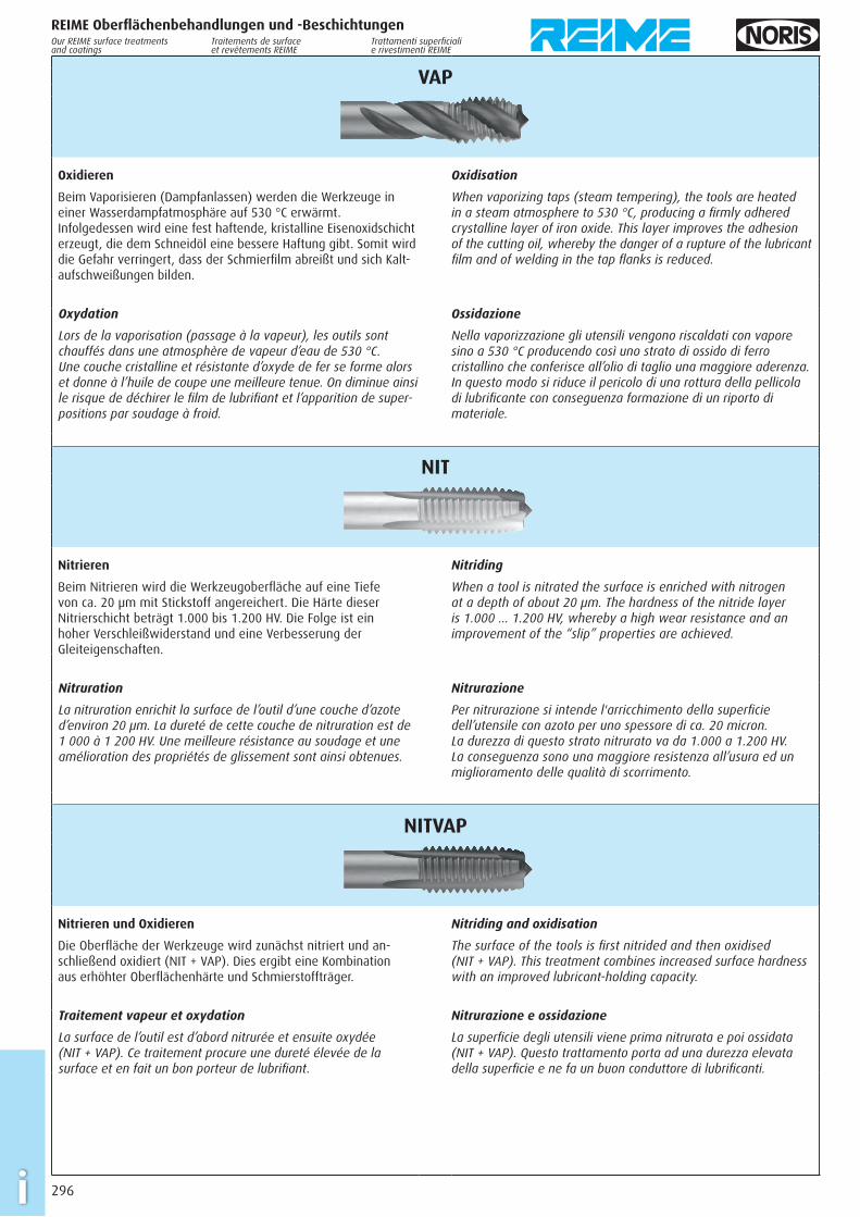
Oxidieren
Beim Vaporisieren (Dampfanlassen) werden die Werkzeuge in einer Wasserdampfatmosphäre auf 530 °C erwärmt. Infolgedessen wird eine fest haftende, kristalline Eisenoxidschicht erzeugt, die dem Schneidöl eine bessere Haftung gibt. Somit wird die Gefahr verringert, dass der Schmierfi lm abreißt und sich Kalt-aufschweißungen bilden.
Oxidisation
When vaporizing taps (steam tempering), the tools are heated in a steam atmosphere to 530 °C, producing a fi rmly adhered crystalline layer of iron oxide. This layer improves the adhesion of the cutting oil, whereby the danger of a rupture of the lubricant fi lm and of welding in the tap fl anks is reduced.
Oxydation
Lors de la vaporisation (passage à la vapeur), les outils sont chauffés dans une atmosphère de vapeur d’eau de 530 °C. Une couche cristalline et résistante d’oxyde de fer se forme alors et donne à l’huile de coupe une meilleure tenue. On diminue ainsi le risque de déchirer le fi lm de lubrifi ant et l’apparition de super-positions par soudage à froid.
Ossidazione
Nella vaporizzazione gli utensili vengono riscaldati con vapore sino a 530 °C producendo così uno strato di ossido di ferro cristallino che conferisce all’olio di taglio una maggiore aderenza. In questo modo si riduce il pericolo di una rottura della pellicola di lubrifi cante con conseguenza formazione di un riporto di materiale.
NIT
Nitrieren
Beim Nitrieren wird die Werkzeugoberfl äche auf eine Tiefe von ca. 20 µm mit Stickstoff angereichert. Die Härte dieser Nitrierschicht beträgt 1.000 bis 1.200 HV. Die Folge ist ein hoher Verschleißwiderstand und eine Verbesserung der Gleiteigenschaften.
Nitriding
When a tool is nitrated the surface is enriched with nitrogen at a depth of about 20 µm. The hardness of the nitride layer is 1.000 … 1.200 HV, whereby a high wear resistance and an improvement of the “slip” properties are achieved.
Nitruration
La nitruration enrichit la surface de l’outil d’une couche d’azote d’environ 20 µm. La dureté de cette couche de nitruration est de 1 000 à 1 200 HV. Une meilleure résistance au soudage et une amélioration des propriétés de glissement sont ainsi obtenues.
Nitrurazione
Per nitrurazione si intende l'arricchimento della superfi cie dell’utensile con azoto per uno spessore di ca. 20 micron. La durezza di questo strato nitrurato va da 1.000 a 1.200 HV. La conseguenza sono una maggiore resistenza all’usura ed un miglioramento delle qualità di scorrimento.
NITVAP
Nitrieren und Oxidieren
Die Oberfl äche der Werkzeuge wird zunächst nitriert und an-schließend oxidiert (NIT + VAP). Dies ergibt eine Kombination aus erhöhter Oberfl ächenhärte und Schmierstoffträger.
Nitriding and oxidisation
The surface of the tools is fi rst nitrided and then oxidised (NIT + VAP). This treatment combines increased surface hardness with an improved lubricant-holding capacity.
Traitement vapeur et oxydation
La surface de l’outil est d’abord nitrurée et ensuite oxydée (NIT + VAP). Ce traitement procure une dureté élevée de la surface et en fait un bon porteur de lubrifi ant.
Nitrurazione e ossidazione
La superfi cie degli utensili viene prima nitrurata e poi ossidata (NIT + VAP). Questo trattamento porta ad una durezza elevata della superfi cie e ne fa un buon conduttore di lubrifi canti.
297 i
REIME Oberfl ächenbehandlungen und -BeschichtungenOur REIME surface treatments and coatings
Traitements de surface et revêtements REIME
Trattamenti superfi ciali e rivestimenti REIME
TIN
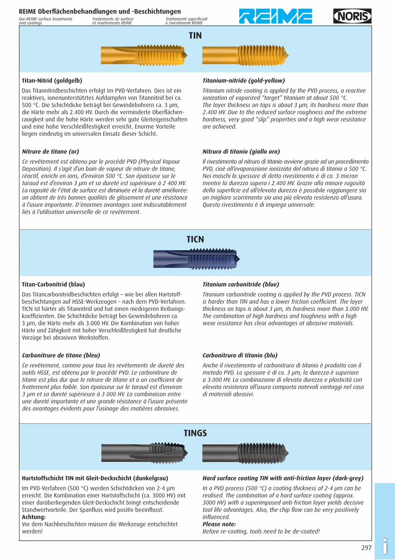
Titan-Nitrid (goldgelb)
Das Titannitridbeschichten erfolgt im PVD-Verfahren. Dies ist ein reaktives, ionenunterstütztes Aufdampfen von Titannitrid bei ca. 500 °C. Die Schichtdicke beträgt bei Gewindebohrern ca. 3 µm, die Härte mehr als 2.400 HV. Durch die verminderte Oberfl ächen-rauigkeit und die hohe Härte werden sehr gute Gleiteigenschaften und eine hohe Verschleißfestigkeit erreicht. Enorme Vorteile liegen eindeutig im universalen Einsatz dieser Schicht.
Titanium-nitride (gold-yellow)
Titanium nitride coating is applied by the PVD process, a reactive ionization of vaporized “target” titanium at about 500 °C. The layer thickness on taps is about 3 µm, its hardness more than 2.400 HV. Due to the reduced surface roughness and the extreme hardness, very good “slip” properties and a high wear resistance are achieved.
Nitrure de titane (or)
Ce revêtement est obtenu par le procédé PVD (Physical Vapour Deposition). Il s’agit d’un bain de vapeur de nitrure de titane, réactif, enrichi en ions, d’environ 500 °C. Son épaisseur sur le taraud est d’environ 3 µm et sa dureté est supérieure à 2 400 HV. La rugosité de l’état de surface est diminuée et la dureté améliorée: on obtient de très bonnes qualités de glissement et une résistance à l’usure importante. D’énormes avantages sont indiscutablement liés à l’utilisation universelle de ce revêtement.
Nitruro di titanio (giallo oro)
Il rivestimento al nitruro di titanio avviene grazie ad un procedimento PVD, cioè all’evaporazione ionizzata del nitruro di titanio a 500 °C. Nei maschi lo spessore di detto rivestimento è di ca. 3 micron mentre la durezza supera i 2.400 HV. Grazie alla minore rugosità della superfi cie ed all’elevata durezza è possibile raggiungere sia un migliore scorrimento sia una più elevata resistenza all’usura. Questo rivestimento è di impiego universale.
TICN
Titan-Carbonitrid (blau)
Das Titancarbonitridbeschichten erfolgt – wie bei allen Hartstoff-beschichtungen auf HSSE-Werkzeugen – nach dem PVD-Verfahren. TICN ist härter als Titannitrid und hat einen niedrigeren Reibungs-koeffi zienten. Die Schichtdicke beträgt bei Gewindebohrern ca. 3 µm, die Härte mehr als 3.000 HV. Die Kombination von hoher Härte und Zähigkeit mit hoher Verschleißfestigkeit hat deutliche Vorzüge bei abrasiven Werkstoffen.
Titanium carbonitride (blue)
Titanium carbonitride coating is applied by the PVD process. TICN is harder than TIN and has a lower friction coeffi cient. The layer thickness on taps is about 3 µm, its hardness more than 3.000 HV. The combination of high hardness and toughness with a high wear resistance has clear advantages at abrasive materials.
Carbonitrure de titane (bleu)
Ce revêtement, comme pour tous les revêtements de dureté des outils HSSE, est obtenu par le procédé PVD. Le carbonitrure de titane est plus dur que le nitrure de titane et a un coeffi cient de frottement plus faible. Son épaisseur sur le taraud est d’environ 3 µm et sa dureté supérieure à 3 000 HV. La combinaison entre une dureté importante et une grande résistance à l’usure présente des avantages évidents pour l’usinage des matières abrasives.
Carbonitruro di titanio (blu)
Anche il rivestimento al carbonitruro di titanio è prodotto con il metodo PVD. Lo spessore è di ca. 3 µm; la durezza è superiore a 3.000 HV. La combinazione di elevata durezza e plasticità con elevata resistenza all’usura comporta notevoli vantaggi nel caso di materiali abrasivi.
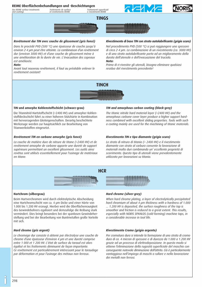
TINGS
Hartstoffschicht TIN mit Gleit-Deckschicht (dunkelgrau)
Im PVD-Verfahren (500 °C) werden Schichtdicken von 2-4 µm erreicht. Die Kombination einer Hartstoffschicht (ca. 3000 HV) mit einer darüber liegenden Gleit-Deckschicht bringt entscheidende Standwertvorteile. Der Spanfl uss wird positiv beeinfl usst.Achtung: Vor dem Nachbeschichten müssen die Werkzeuge entschichtet werden!
Hard surface coating TIN with anti-friction layer (dark-grey)
In a PVD process (500 °C) a coating thickness of 2-4 µm can be realised. The combination of a hard surface coating (approx. 3000 HV) with a superimposed anti-friction layer yields decisive tool life advantages. Also, the chip fl ow can be very positively infl uenced.Please note: Before re-coating, tools need to be de-coated!
298i
REIME Oberfl ächenbehandlungen und -BeschichtungenOur REIME surface treatments and coatings
Traitements de surface et revêtements REIME
Trattamenti superfi ciali e rivestimenti REIME
TINGS
Revêtement dur TIN avec couche de glissement (gris foncé)
Dans le procédé PVD (500 °C) une épaisseur de couche jusqu’à environ 2-4 µm peut être atteinte. La combinaison d’un revêtement dur (environ 3000 HV) et d’une couche de glissement mène à une amélioration de la durée de vie. L’évacuation des copeaux est améliorée.Note: Avant tout nouveau revêtement, il faut au préalable enlever le revêtement existant!
Rivestimento di base TIN con strato autolubrifi cante (grigio scuro)
Nel procedimento PVD (500 °C) si può raggiungere uno spessore di circa 2-4 µm. La combinazione di un rivestimento (ca. 3000 HV) e di uno strato autolubrifi cante porta ad un miglioramento della durata dell’utensile e dell’evacuazione del truciolo.Nota: Prima di ri-rivestire gli utensili, bisogna eliminare qualsiasi residuo del rivestimento precedente!
TINCH
TIN und amorphe Kohlenstoffschicht (schwarz-grau)
Die Titannitrid-Hartstoffschicht (>2400 HV) und amorpher Kohlen-stoffdeckschicht führt zu einer höheren Stützhärte in Kombination mit hervorragenden Gleiteigenschaften. Derartig beschichtete Werkzeuge werden zur hauptsächlich zur Bearbeitung von Titanwerkstoffen eingesetzt.
TIN and amorphous carbon coating (black-grey)
The titanic nitride hard material layer (>2400 HV) and the amorphous carbone cover layer produce a higher support hard-ness combined with excellent sliding properties. Tools with such a coating mainly are used for the machining of titanic materials.
Revêtement TIN en carbone amorphe (gris foncé)
La couche de matière dure de nitrure de titane (>2400 HV) et de revêtement amorphe de carbone apporte une dureté de support supérieure permettant un excellent glissement. Les outils ainsi revêtus sont utilisés essentiellement pour l'usinage de matériaux en titane.
Rivestimento TIN e tipo diamante (grigio scuro)
Lo strato di nitruro di titanio (> 2400 HV) e il rivestimento diamante con strato al carburo consente la lavorazione di materiali molto duri combinando un’ eccellente proprietà di scorrimento. Questo tipo di utensili viene prevalentemente utilizzato per lavorazioni su titanio.
HCR
Hartchrom (silbergrau)
Beim Hartverchromen wird durch elektrolytische Abscheidung eine Hartchromschicht von ca. 4 µm Dicke und einer Härte von 1.000 bis 1.200 HV erzeugt. Hierbei wird die Oberfl ächenrauigkeit des Gewindebohrers egalisiert und demzufolge die Reibung stark vermindert. Dies bringt besonders bei der spanlosen Gewindeher-stellung und bei der Bearbeitung von Buntmetallen große Vorteile mit sich.
Hard chrome (silver-grey)
When hard chrome plating, a layer of electrolytically precipitated hard chromium of about 4 µm thickness with a hardness of 1.000 … 1.200 HV is deposited, the surface roughness of the tap is smoother and friction is reduced to a great extent. This results, especially with NORIS SPANLOS (cold-forming) machine taps, in a considerable increase in tool life.
Hard chrome (gris argent)
Le chromage dur consiste à obtenir par électrolyse une couche de chrome d’une épaisseur d’environ 4 µm et une dureté comprise entre 1 000 et 1 200 HV. L’état de surface du taraud est alors égalisé et les frottements diminuent de façon importante. Ce revêtement est particulièrement intéressant pour le taraudage par déformation et pour l’usinage des métaux non ferreux.
Rivestimento Cromo (grigio argento)
Per cromatura dura si intende la formazione di uno strato di cromo duro di ca. 4 micron di spessore e di durezza da 1.000 a 1.200 HV grazie ad un processo di elettrodeposizione. In questo modo si ottiene l’eliminazione della rugosità superfi ciale del maschio con conseguente notevole diminuzione dell’attrito. Ciò è particolarmente vantaggioso nell’impiego di maschi a rullare e nella lavorazione dei metalli non ferrosi.
299 i
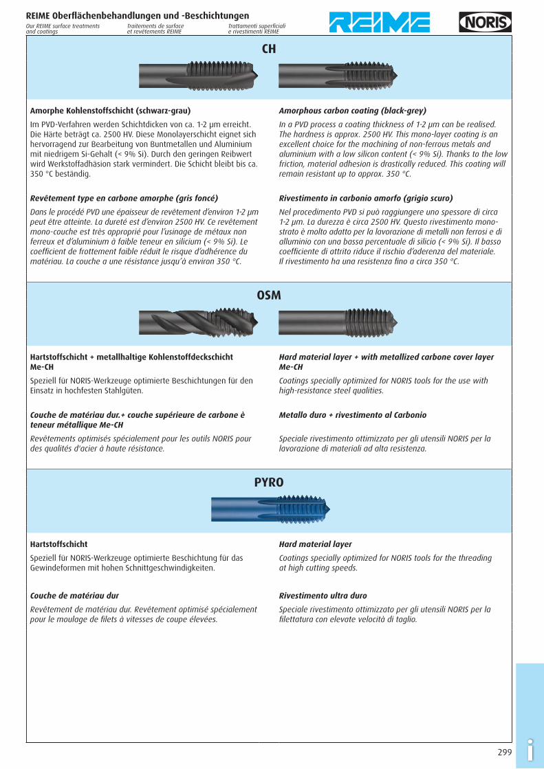
CH
Amorphe Kohlenstoffschicht (schwarz-grau)
Im PVD-Verfahren werden Schichtdicken von ca. 1-2 µm erreicht. Die Härte beträgt ca. 2500 HV. Diese Monolayerschicht eignet sich hervor ragend zur Bearbeitung von Buntmetallen und Aluminium mit niedrigem Si-Gehalt (< 9% Si). Durch den geringen Reibwert wird Werkstoffadhäsion stark vermindert. Die Schicht bleibt bis ca. 350 °C beständig.
Amorphous carbon coating (black-grey)
In a PVD process a coating thickness of 1-2 µm can be realised. The hardness is approx. 2500 HV. This mono-layer coating is an excellent choice for the machining of non-ferrous metals and aluminium with a low silicon content (< 9% Si). Thanks to the low friction, material adhesion is drastically reduced. This coating will remain resistant up to approx. 350 °C.
Revêtement type en carbone amorphe (gris foncé)
Dans le procédé PVD une épaisseur de revêtement d’environ 1-2 µm peut être atteinte. La dureté est d’environ 2500 HV. Ce revêtement mono-couche est très approprié pour l’usinage de métaux non ferreux et d’aluminium à faible teneur en silicium (< 9% Si). Le coeffi cient de frottement faible réduit le risque d’adhérence du matériau. La couche a une résistance jusqu’à environ 350 °C.
Rivestimento in carbonio amorfo (grigio scuro)
Nel procedimento PVD si può raggiungere uno spessore di circa 1-2 µm. La durezza è circa 2500 HV. Questo rivestimento mono-strato è molto adatto per la lavorazione di metalli non ferrosi e di alluminio con una bassa percentuale di silicio (< 9% Si). Il basso coeffi ciente di attrito riduce il rischio d’aderenza del materiale. Il rivestimento ha una resistenza fi no a circa 350 °C.
OSM
Hartstoffschicht + metallhaltige Kohlenstoffdeckschicht Me-CH
Speziell für NORIS-Werkzeuge optimierte Beschichtungen für den Einsatz in hochfesten Stahlgüten.
Hard material layer + with metallized carbone cover layer Me-CH
Coatings specially optimized for NORIS tools for the use with high-resistance steel qualities.
Couche de matériau dur.+ couche supérieure de carbone è teneur métallique Me-CH
Revêtements optimisés spécialement pour les outils NORIS pour des qualités d'acier à haute résistance.
Metallo duro + rivestimento al Carbonio
Speciale rivestimento ottimizzato per gli utensili NORIS per la lavorazione di materiali ad alta resistenza.
PYRO
Hartstoffschicht
Speziell für NORIS-Werkzeuge optimierte Beschichtung für das Gewindeformen mit hohen Schnittgeschwindigkeiten.
Hard material layer
Coatings specially optimized for NORIS tools for the threading at high cutting speeds.
Couche de matériau dur
Revêtement de matériau dur. Revêtement optimisé spécialement pour le moulage de fi lets à vitesses de coupe élevées.
Rivestimento ultra duro
Speciale rivestimento ottimizzato per gli utensili NORIS per la fi lettatura con elevate velocità di taglio.
REIME Oberfl ächenbehandlungen und -BeschichtungenOur REIME surface treatments and coatings
Traitements de surface et revêtements REIME
Trattamenti superfi ciali e rivestimenti REIME
300i
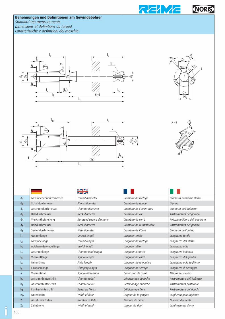
Benennungen und Defi nitionen am Gewindebohrer Standard tap measurementsDimensions et defi nitions du taraudCaratteristiche e defi nizioni del maschio
d 2
l1
k
d 3 d 4
y
d 1
l3 (l7)l2 l5
lEl8l4
A
B
χr
(l6)
Zb
Z
d7
h f
Nb
γpγr
d 5k
1
lE
l2l1
(l7)l5
l8l4
d 3d 1
d 6y
χrA
B
d 2
h r
h a
αpA - B
d1 Gewindenenndurchmesser Thread diameter Diamètre du fi letage Diametro nominale fi letto
d2 Schaftdurchmesser Shank diameter Diamètre de queue Gambo
d3 Anschnittdurchmesser Chamfer diameter Diamètre de l‘avant-trou Diametro dell’imbocco
d4 Halsdurchmesser Neck diameter Diamètre du cou Rastrematura del gambo
d5 Vierkantfreidrehung Recessed square diameter Diamètre du carré Rotozione libera dell‘quadrata
d6 Halsdurchmesser Neck diameter Diamètre de rotation libre Rastrematura del gambo
d7 Seelendurchmesser Web diameter Diamètre de l‘âme Diametro dell‘anima
l1 Gesamtlänge Overall length Longueur totale Lunghezza totale
l2 Gewindelänge Thread length Longueur du fi letage Lunghezza del fi letto
l3 nutzbare Gewindelänge Useful length Longueur utile Lunghezza utile
l4 Anschnittlänge Chamfer lead length Longueur d‘entrée Lunghezza imbocco
l5 Vierkantlänge Square length Longueur du carré Lunghezza del quadro
l8 Nutenlänge Flute length Longueur de la goujure Lunghezza gola tagliente
lE Einspannlänge Clamping length Longueur de serrage Lunghezza di serraggio
a Vierkantmaß Square dimension Dimension de carré Misura del quadro
ha Anschnitthinterschliff Chamfer relief Détalonnage ébauche Rastrematura dell’imbocco
hr Anschnitthinterschliff Chamfer relief Détalonnage ébauche Rastrematura posteriore
hf Flankenhinterschliff Relief on fl anks Détalonnage fl anc Rastrematura dei fi anchi
Nb Nutenbreite Width of fl ute Largeur de la goujure Larghezza gola tagliente
Z Anzahl der Nuten Number of fl utes Nombre de dents Numero dei denti
Zb Zahnbreite Width of land Largeur de dent Larghezza del dente
301 i
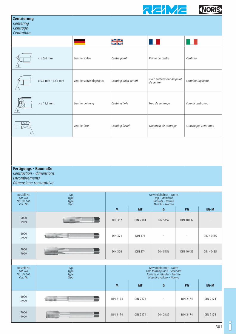
Zentrierung CenteringCentrageCentratura
Z1
< ø 5,6 mm Zentrierspitze Centre point Pointe de centre Centrino
Z2
ø 5,6 mm - 12,8 mm Zentrierspitze abgesetzt Centring point set off avec enlèvement du point de centre Centrino taglianto
Z3
> ø 12,8 mm Zentrierbohrung Centring hole Trou de centrage Foro di centratura
Z4
Zentrierfase Centring bevel Chanfrein de centrage Smusso per centratura
Fertigungs - Baumaße Contruction - dimensionsEncombrementsDimensione construttiva
Bestell-Nr. Cat. No.
No. de Cat.Cat. Nr.
Typ Type TypeTipo
Gewindebohrer – Norm Tap – Standard
Tarauds – NormeMaschi – Norma
M MF G PG EG-M
5000
5999DIN 352 DIN 2181 DIN 5157 DIN 40432 -
6000
6999DIN 371 DIN 371 - - DIN 40435
7000
7999DIN 376 DIN 374 DIN 5156 DIN 40433 DIN 40435
Bestell-Nr. Cat. No.
No. de Cat.Cat. Nr.
Typ Type TypeTipo
Gewindeformer – Norm Cold forming taps – StandardTarauds à refouler – NormeMaschi a rullare – Norma
M MF G PG EG-M
6000
6999DIN 2174 DIN 2174 - DIN 2174 DIN 2174
7000
7999DIN 2174 DIN 2174 DIN 2189 DIN 2174 DIN 2174
302i
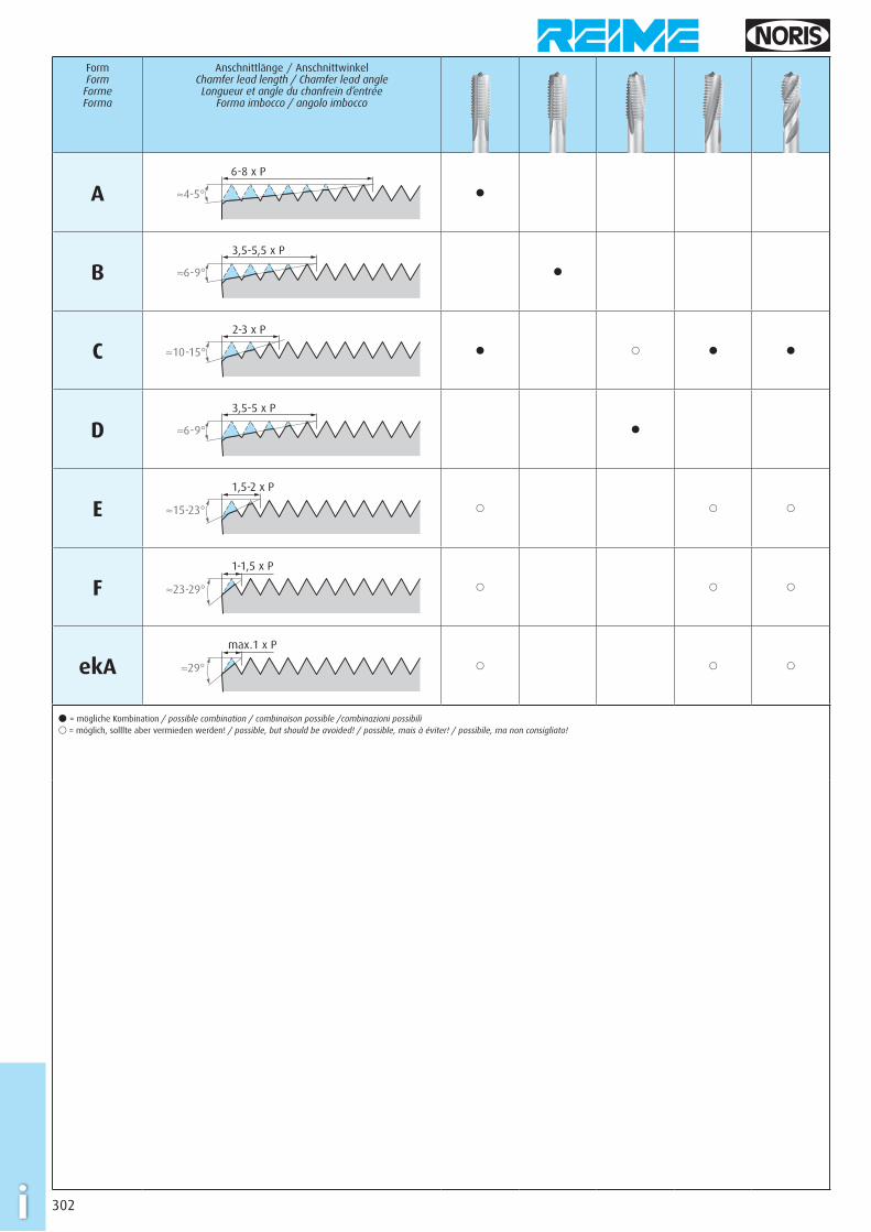
Form Form
FormeForma
Anschnittlänge / Anschnittwinkel Chamfer lead length / Chamfer lead angleLongueur et angle du chanfrein d’entrée
Forma imbocco / angolo imbocco
A6-8 x P
≈4-5° �
B3,5-5,5 x P
≈6-9° �
C2-3 x P
≈10-15° � � � �
D3,5-5 x P
≈6-9° �
E1,5-2 x P
≈15-23° � � �
F1-1,5 x P
≈23-29° � � �
ekAmax.1 x P
≈29° � � �
� = mögliche Kombination / possible combination / combinaison possible /combinazioni possibili� = möglich, solllte aber vermieden werden! / possible, but should be avoided! / possible, mais à éviter! / possibile, ma non consigliato!
303 i
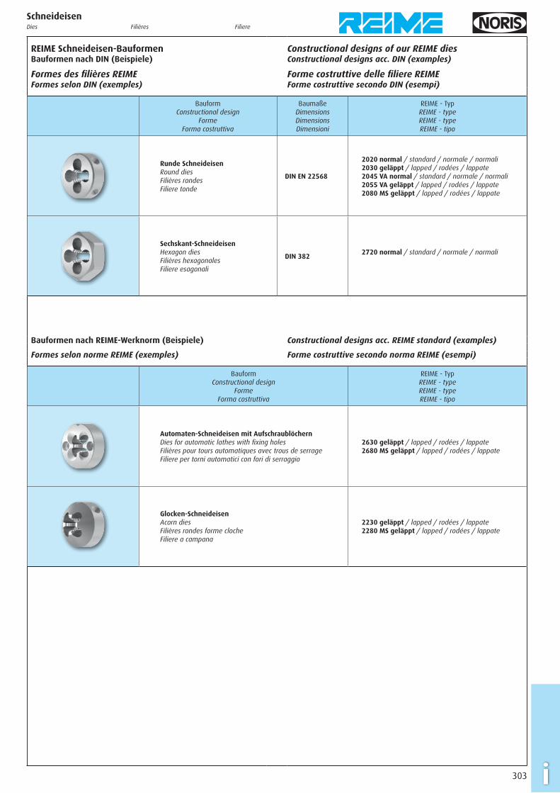
Schneideisen Dies Filières Filiere
REIME Schneideisen-Bauformen Bauformen nach DIN (Beispiele)
Formes des fi lières REIME Formes selon DIN (exemples)
Constructional designs of our REIME dies Constructional designs acc. DIN (examples)
Forme costruttive delle fi liere REIME Forme costruttive secondo DIN (esempi)
Bauform Constructional design
FormeForma costruttiva
Baumaße DimensionsDimensionsDimensioni
REIME - Typ REIME - typeREIME - typeREIME - tipo
Runde Schneideisen Round dies Filières rondesFiliere tonde
DIN EN 22568
2020 normal / standard / normale / normali2030 geläppt / lapped / rodées / lappate2045 VA normal / standard / normale / normali2055 VA geläppt / lapped / rodées / lappate2080 MS geläppt / lapped / rodées / lappate
Sechskant-Schneideisen Hexagon dies Filières hexagonalesFiliere esagonali
DIN 3822720 normal / standard / normale / normali
Bauformen nach REIME-Werknorm (Beispiele) Constructional designs acc. REIME standard (examples)
Formes selon norme REIME (exemples) Forme costruttive secondo norma REIME (esempi)
Bauform Constructional design
FormeForma costruttiva
REIME - Typ REIME - typeREIME - typeREIME - tipo
Automaten-Schneideisen mit Aufschraublöchern Dies for automatic lathes with fi xing holes Filières pour tours automatiques avec trous de serrageFiliere per torni automatici con fori di serraggio
2630 geläppt / lapped / rodées / lappate2680 MS geläppt / lapped / rodées / lappate
Glocken-Schneideisen Acorn dies Filières rondes forme clocheFiliere a campana
2230 geläppt / lapped / rodées / lappate2280 MS geläppt / lapped / rodées / lappate

304i
Schneideisen Dies Filières Filiere
Geometrie Erklärungen
Explications Géométrie
Geometry Explanations
Geometria Dichiarazioni
2020, 2030, 2230, 2720
Für gut spanbare Stahlwerkstoffe
Diese Schneideisen sind mit einem Schälanschnitt ausgeführt, um in langspanenden Materialien dem Span eine axiale Richtung zu geben.
For steels with good machining capacity
These dies are made with a spiral point which, in long-chipping materials, guides the chip in an axial direction.
Pour les aciers faciles à usiner
Ces fi lières sont munies d’une entrée GUN pour donner au copeau, dans des matières à copeaux longs, une direction axiale.
Per acciai di buona lavorabilità
Queste fi liere sono munite di un imbocco corretto per dare al truciolo, in materiali a truciolo lungo, una direzione assiale.
2045, 2055, 2230, 2720
Für nichtrostende Stahlwerkstoffe und Stahlwerkstoffe
Ein etwas längerer Anschnitt ergibt eine bessere Spanaufteilung. Der Schälanschnitt führt das Spanmaterial in axialer Richtung ab, somit kann der Kühlschmierstoff ungehindert nachfl ießen.
For stainless steel materials and steel materials
The chamfer of these dies is a little longer, and provides an im-proved chip division. A spiral point ensures chip transport in an axial direction, so that the coolant-lubricant can fl ow freely.
Pour aciers inoxydables et aciers
L’entrée légèrement plus longue de ces fi lières permet une meilleure division du copeau. L’entrée GUN garantit une évacuation du copeau en direction axiale de façon à ce que le lubrifi ant puisse circuler sans problème.
Per acciai inossidabili ed acciai
L’imbocco leggermente più lungo di queste fi liere porta ad una divisione migliore del truciolo. L’imbocco corretto garantisce un’evacuazione del truciolo in direzione assiale in modo che il lubrorefrigerante possa fl uire senza problemi.
2080, 2280, 2680
Für Kupfer-Zink-Legierungen (Messing, kurzspanend)
Ohne Schälanschnitt für axialkraftneutrales Anschneiden sowie mit reduziertem Spanwinkel für einen stabilen Schneidkeil.
For copper-zinc alloys (brass, short-chipping)
Design without spiral point for a fi rst cutting phase without any axial force, and with a reduced rake angle for a stable cutting wedge.
Pour alliages cuivre-zinc (laiton, copeaux courts)
Version sans entrée GUN pour une coupe sur l’entrée sans force axiale ainsi qu’un angle de coupe réduit pour renforcer l’arête de coupe rigide.
Per leghe rame-zinco (ottone, a truciolo corto)
Versione senza imbocco corretto per un taglio senza forza assiale oppure con angolo di spoglia ridotto per un tagliente stabile.
Oberfl ächenbehandlungen
Traitement de surface
Surface treatment
Trattamento di superfi cie
2020, 2030, 2230, 2720
Normal
Ohne besondere Oberfl ächenbehandlung.
Standard
No special surface treatment.
Normale
Sans traitement de surface spécifi que.
Normali
Senza trattamento superfi ciale.
2020, 2030, 2230, 2720
Geläppt
Durch die geläppte Oberfl äche im Gewinde wird Reibung herab-gesetzt und somit ein besseres Schneidergebnis erzielt.
Lapped
The lapped thread surface reduces friction and helps to achieve an improved cutting performance.
Rodée
La surface rodée du fi let réduit la friction et aide à atteindre un meilleur résultat de coupe.
Lappate
La superfi cie lappata della fi lettatura riduce la frizione e aiuta a realizzare un migliore risultato di taglio.
305 i
Schneideisen Dies Filières Filiere
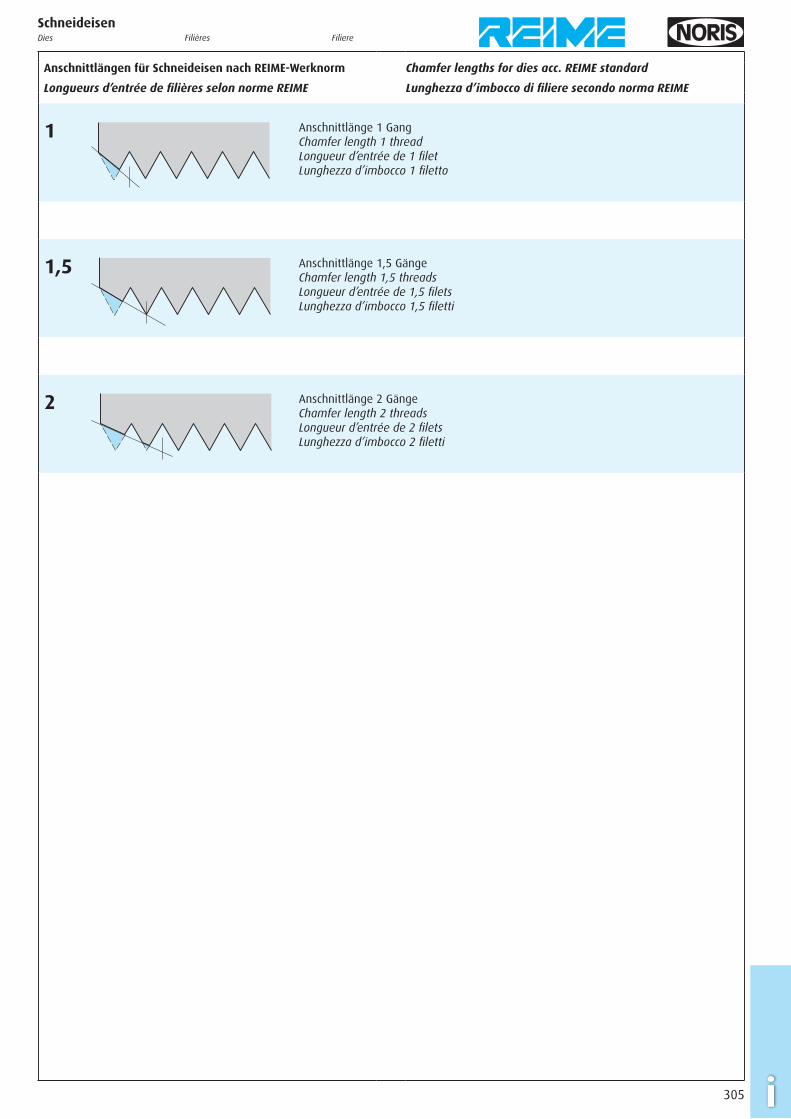
Anschnittlängen für Schneideisen nach REIME-Werknorm
Longueurs d’entrée de fi lières selon norme REIME
Chamfer lengths for dies acc. REIME standard
Lunghezza d’imbocco di fi liere secondo norma REIME
1 Anschnittlänge 1 Gang Chamfer length 1 thread Longueur d’entrée de 1 fi let Lunghezza d’imbocco 1 fi letto
1,5 Anschnittlänge 1,5 Gänge Chamfer length 1,5 threads Longueur d’entrée de 1,5 fi lets Lunghezza d’imbocco 1,5 fi letti
2 Anschnittlänge 2 Gänge Chamfer length 2 threads Longueur d’entrée de 2 fi lets Lunghezza d’imbocco 2 fi letti
306i
GewindelehrenThread gauges Calibres fi letés Calibri fi lettati
Allgemeines
Für das Metrische ISO-Gewinde ist in DIN ISO 1502 ein Lehren-system festgelegt mit dem Zweck, eine uneingeschränkte Austauschbarkeit der Werkstückgewinde zu gewährleisten.
Es gelten folgende Grundsätze:1. Der Hersteller darf kein Werkstückgewinde liefern, dessen
Gewinde-Istmaß außerhalb der festgelegten Grenzen liegt (z.B. der Flanken durchmesser und der Paarungsfl anken-durchmesser).
2. Der Besteller darf kein Werkstückgewinde zurückweisen, dessen Gewinde-Istmaß innerhalb der festgelegten Grenzen liegt (z.B. der Flankendurchmesser und der Paarungsfl anken-durchmesser).
Natürlich werden heute in der modernen Gewindefertigung auch andere Prüfmethoden angewandt, z.B. Messen mit anzeigenden Messgeräten. Bei Anwendung anderer Methoden ist darauf zu achten, dass diese zu gleichen Ergebnissen führen.
In Zweifelsfällen sind für das Metrische ISO-Gewinde die in der Norm DIN ISO 1502 empfohlenen Lehren für die Prüfung entscheidend. Für andere Gewindesysteme (z.B. Amerikanische Gewinde) gelten andere Lehrennormen.
Wird in der Fertigung hauptsächlich durch Messen geprüft, so ist es unum gänglich, dass eine stichprobenmäßige Prüfung mit den genormten Lehren durchgeführt wird. Die Bezugstemperatur für die Maße der Lehren und Werkstücke ist 20 °C. Wird bei anderen Temperaturen geprüft, sind die Ausdehnungskoeffi zienten zu berücksichtigen.
General information
For the Metric ISO thread, a gauge system is specifi ed in DIN ISO 1502 for the purpose of securing the unlimited exchangeability of workpiece threads.
The following basic principles apply:1. The manufacturer must not supply a workpiece thread the
actual thread size of which is outside of the specifi ed limits (e.g. pitch diameter or mating pitch diameter).
2. The buyer must not reject a workpiece thread the actual thread size of which is inside of the specifi ed limits (e.g. pitch diameter or mating pitch diameter).
In modern thread production, there are of course other inspection methods also, e.g. measuring with dial-type measuring instruments. Whenever other methods are applied it is important to make sure that the same results are achieved.
In any case of doubt, the gauges recommended in the standard DIN ISO 1502 will decide the result of the inspection for the Metric ISO thread. For other thread systems (e.g. American threads), other gauge standards apply.
If the inspection work in production is done mainly by measuring, it is still absolutely necessary to perform random sample inspection with the standardised gauges. The reference temperature for the gauge and workpiece dimensions is 20 °C. If inspections are done at other temperatures, the corresponding expansion coeffi cients have to be taken into account.
Informations générales
Pour le fi letage Métrique ISO, un système de contrôle est défi ni dans la DIN ISO 1502 avec l’objectif de garantir l’interchangeabilité illimitée des pièces comportant un fi let.
Les suivants principes de base sont appliqués:1. Le fabricant ne peut pas fournir une pièce avec un fi let ayant
une mesure effective en dehors des limites défi nies (p. ex. le diamètre sur fl ancs et le diamètre d’appariement sur fl ancs).
2. Le client ne peut pas rejeter une pièce avec un fi let ayant une mesure effective dans les limites défi nies (p. ex. le diamètre sur fl ancs et le diamètre d’appariement sur fl ancs).
Dans la réalisation de fi lets actuelle, sont également utilisées d’autres méthodes de contrôle, p. ex. la mesure au moyen d’appareils de mesure. Lors de l’utilisation d’autres méthodes, il faut s’assurer que ces méthodes mènent au même résultat.
En cas de doute, les calibres préconisés dans la norme DIN ISO 1502 sont décisifs pour le contrôle du fi letage Métrique ISO.Pour autres systèmes de fi letage (p. ex. fi letages américains), d’autres normes de calibres s’appliquent.
Si le contrôle lors de la production s’effectue principalement par mesure, il est absolument nécessaire réaliser un contrôle par échantillonnage avec les calibres normalisés. La température de référence pour les calibres et les pièces lors de la mesure est 20 °C. Si le contrôle est effectué à autre température, il faut considérer les coeffi cients de dilatation.
Informazioni generali
Per la fi lettatura ISO Metrica, il sistema di controllo è defi nito dalla norma DIN ISO 1502 con lo scopo di garantire l’intercambiabilità illimitata di pezzi con fi lettature.
I principi di base sono i seguenti:1. Il fabbricante non può fornire un pezzo con un fi letto con
misura effettiva al di fuori dei limiti defi niti (p. es. il diametro medio o il diametro medio d’accoppiamento).
2. Il cliente non può scartare un pezzo con un fi letto con misura effettiva entro i limiti defi niti (p. es. il diametro medio o il diametro medio d’accoppiamento).
Nella produzione di fi lettature attuale vengono utilizzati anche altri metodi di controllo, p. es. la misurazione per mezzo di apparecchi di misurazione. Nell’applicazione di altri metodi bisogna assicurarsi che questi metodi portino allo stesso risultato.
Nel caso di dubbio, i calibri consigliati nella norma DIN ISO 1502 sono decisivi per il controllo della fi lettatura ISO Metrica.Per altri sistemi di fi lettatura (p. es. fi lettature americane) vengono applicate, per i calibri, altre norme.
Se il controllo nella produzione viene effettuato principalmente tramite misurazione, è assolutamente necessario realizzare un controllo a campione con calibri normalizzati. La temperatura di riferimento per i calibri ed i pezzi nella misurazione è 20 °C. Se il controllo è effettuato ad altra temperatura, bisogna considerare i coeffi cienti di dilatazione termica.
307 i
GewindelehrenThread gauges Calibres fi letés Calibri fi lettati
Gewindelehren für Innengewinde
Für die Lehrung des Innengewindes werden der Gewinde-Gutlehr-dorn und der Gewinde-Ausschusslehrdorn verwendet. Bis Gewinde-durchmesser 40 mm sind Gut- und Ausschusslehrdorn auf einen gemeinsamen Griff montiert und werden als Gewinde-Grenzlehr-dorn bezeichnet. Für Aus nahme fälle sind Griffe für Gewinde-Grenz-lehrdorne bis Gewindedurch messer 62 mm nach DIN 2240-2 genormt. Zur Lehrung des Innengewinde-Kerndurchmessers wird ein (glatter) Gut- und Ausschusslehrdorn empfohlen.
Thread gauges for internal threads
The go thread plug gauge and the no-go thread plug gauge are used for the gauging of internal threads. Go and no-go plug gauges are mounted on a common handle for thread diameters up to 40 mm and are designated as go/no-go thread plug gauges. For exceptional cases handles for go/no-go thread plug gauges up to a thread diameter of 62 mm are standardized in DIN 2240-2. A (smooth) go and no-go plug gauge is recommended for gauging the internal thread minor diameter.
Calibres fi letés pour fi lets intérieurs
Le contrôle du taraudage s’effectue au moyen d’un tampon fi leté entre et d’un tampon fi leté n’entre pas. Jusqu’au diamètre de fi let 40 mm le tampon fi leté entre et le tampon fi leté n’entre pas sont montés sur une poignée et sont désignés comme tampon fi leté entre/n’entre pas. Pour des cas exceptionnels, les poignées pour tampons fi letés entre/n’entre pas jusqu’au diamètre de fi let 62 mm sont normalisées dans la DIN 2240-2. Pour le contrôle du diamètre de noyau du taraudage, nous recommandons l’utilisation d’un tampon entre/n’entre pas lisse.
Calibri fi lettati per fi lettature interne
Il controllo della fi lettatura è effettuato per mezzo di un calibro a tampone fi lettato passa e un calibro a tampone fi lettato non passa. Fino al diametro di fi letto 40 mm i lati passa e non passa sono montati su un’unica impugnatura e sono denominati: calibro a tampone passa/non passa. Per casi eccezionali, le impugnature per calibri a tampone passa/non passa fi no a diametro di fi letto 62 mm sono normalizzate nella DIN 2240-2. Per il controllo del diametro di nocciolo della fi lettatura interna, raccomandiamo di utilizzare un calibro a tampone (liscio) passa/non passa.
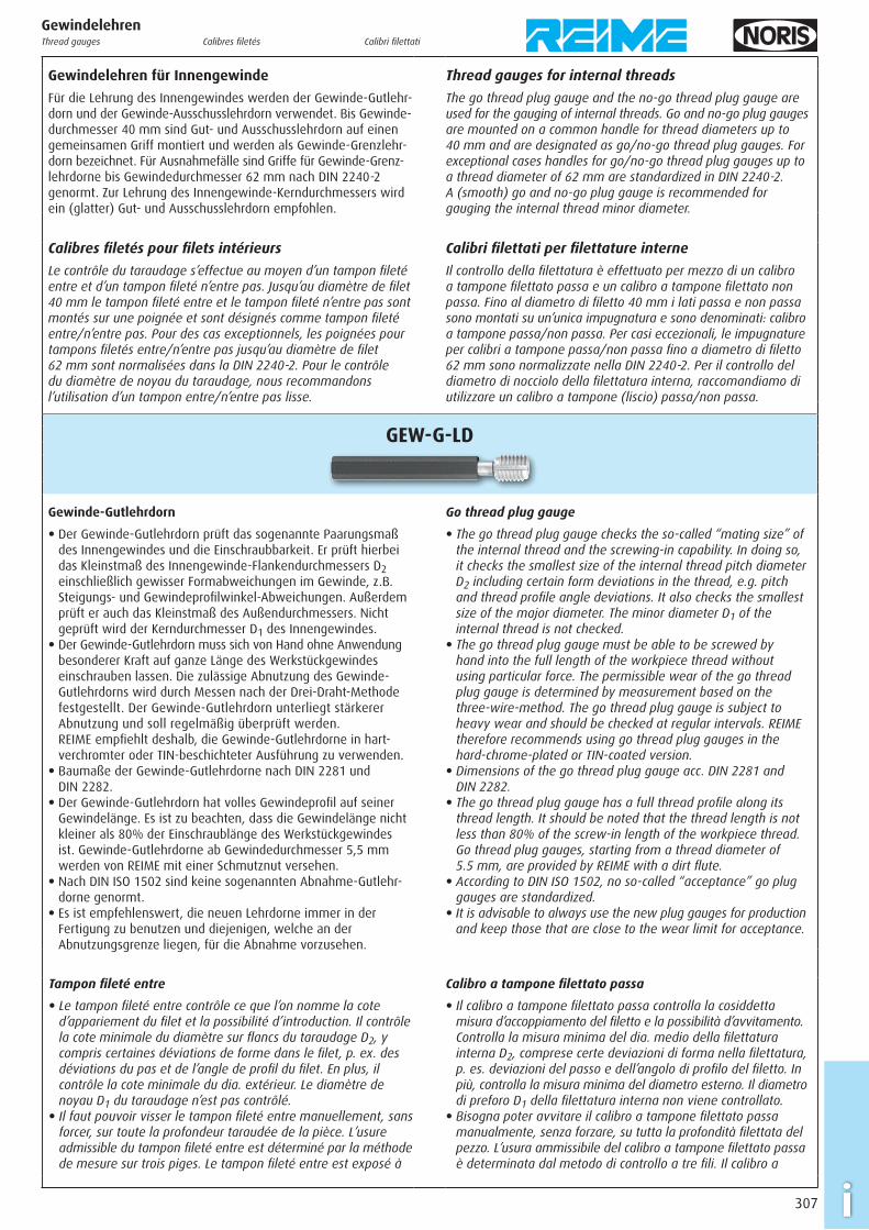
GEW-G-LD
Gewinde-Gutlehrdorn
E Der Gewinde-Gutlehrdorn prüft das sogenannte Paarungsmaß des Innengewindes und die Ein schraub barkeit. Er prüft hierbei das Kleinstmaß des Innengewinde-Flankendurchmessers D2 einschließlich gewisser Formabweichungen im Gewinde, z.B. Steigungs- und Gewindeprofi l winkel-Abweichungen. Außerdem prüft er auch das Kleinstmaß des Außendurchmessers. Nicht geprüft wird der Kerndurchmesser D1 des Innengewindes.
E Der Gewinde-Gutlehrdorn muss sich von Hand ohne Anwendung besonderer Kraft auf ganze Länge des Werkstückgewindes einschrauben lassen. Die zulässige Abnutzung des Gewinde- Gutlehrdorns wird durch Messen nach der Drei-Draht-Methode festgestellt. Der Gewinde-Gutlehrdorn unterliegt stärkerer Abnutzung und soll regelmäßig überprüft werden. REIME empfi ehlt deshalb, die Gewinde-Gutlehrdorne in hart-verchromter oder TIN-beschichteter Aus führung zu verwenden.
E Baumaße der Gewinde-Gutlehrdorne nach DIN 2281 und DIN 2282.
E Der Gewinde-Gutlehrdorn hat volles Gewinde profi l auf seiner Gewindelänge. Es ist zu beachten, dass die Gewindelänge nicht kleiner als 80% der Einschraublänge des Werkstück gewindes ist. Gewinde-Gutlehrdorne ab Gewindedurchmesser 5,5 mm werden von REIME mit einer Schmutznut versehen.
E Nach DIN ISO 1502 sind keine sogenannten Abnahme-Gutlehr-dorne genormt.
E Es ist empfehlenswert, die neuen Lehrdorne immer in der Fertigung zu benutzen und diejenigen, welche an der Abnutzungsgrenze liegen, für die Abnahme vorzusehen.
Go thread plug gauge
E The go thread plug gauge checks the so-called “mating size” of the internal thread and the screwing-in capability. In doing so, it checks the smallest size of the internal thread pitch diameter D2 including certain form deviations in the thread, e.g. pitch and thread profi le angle deviations. It also checks the smallest size of the major diameter. The minor diameter D1 of the internal thread is not checked.
E The go thread plug gauge must be able to be screwed by hand into the full length of the workpiece thread without using particular force. The permissible wear of the go thread plug gauge is determined by measurement based on the three-wire-method. The go thread plug gauge is subject to heavy wear and should be checked at regular intervals. REIME therefore recommends using go thread plug gauges in the hard-chrome-plated or TIN-coated version.
E Dimensions of the go thread plug gauge acc. DIN 2281 and DIN 2282.
E The go thread plug gauge has a full thread profi le along its thread length. It should be noted that the thread length is not less than 80% of the screw-in length of the workpiece thread. Go thread plug gauges, starting from a thread diameter of 5.5 mm, are provided by REIME with a dirt fl ute.
E According to DIN ISO 1502, no so-called “acceptance” go plug gauges are standardized.
E It is advisable to always use the new plug gauges for production and keep those that are close to the wear limit for acceptance.
Tampon fi leté entre
E Le tampon fi leté entre contrôle ce que l’on nomme la cote d’appariement du fi let et la possibilité d’introduction. Il contrôle la cote minimale du diamètre sur fl ancs du taraudage D2, y compris certaines déviations de forme dans le fi let, p. ex. des déviations du pas et de l’angle de profi l du fi let. En plus, il contrôle la cote minimale du dia. extérieur. Le diamètre de noyau D1 du taraudage n’est pas contrôlé.
E Il faut pouvoir visser le tampon fi leté entre manuel lement, sans forcer, sur toute la profondeur taraudée de la pièce. L’usure admissible du tampon fi leté entre est déterminé par la méthode de mesure sur trois piges. Le tampon fi leté entre est exposé à
Calibro a tampone fi lettato passa
E Il calibro a tampone fi lettato passa controlla la cosiddetta misura d’accoppiamento del fi letto e la possibilità d’avvitamento. Controlla la misura minima del dia. medio della fi lettatura interna D2, comprese certe deviazioni di forma nella fi lettatura, p. es. deviazioni del passo e dell’angolo di profi lo del fi letto. In più, controlla la misura minima del diametro esterno. Il diametro di preforo D1 della fi lettatura interna non viene controllato.
E Bisogna poter avvitare il calibro a tampone fi lettato passa manualmente, senza forzare, su tutta la profondità fi lettata del pezzo. L’usura ammissibile del calibro a tampone fi lettato passa è determinata dal metodo di controllo a tre fi li. Il calibro a
308i
une usure plus forte et doit être contrôlé régulière ment. REIME recommande utiliser des tampons fi letés entre avec couche en chrome dur ou avec revêtement TIN.
E Dimensions du tampon fi leté entre selon DIN 2281 et DIN 2282.
E Le tampon fi leté entre présente un profi l plein du fi let sur toute la longueur fi letée. Pour assurer le contrôle du pas, la longueur du tampon fi leté ne doit être inférieure à 80% de la longueur taraudée. Les tampons fi letés entre REIME à partir de dia. 5,5 mm ont une rainure de nettoyage.
E Selon DIN ISO 1502, des tampons fi letés de réception entre ne sont pas normalisés.
E Nous recommandons d’utiliser toujours les tampons fi letés neufs pour la production et les tampons fi letés qui se trouvent à la limite d’usure pour la réception.
tampone fi lettato passa è esposto ad una usura più forte e deve essere regolarmente controllato. REIME racco manda di utilizzare calibri a tampone fi lettati passa con ricopertura in cromo duro o con rivestimento TIN.
E Dimensioni del calibro a tampone fi lettato passa secondo DIN 2281 e DIN 2282.
E Il calibro a tampone fi lettato passa presenta un profi lo di fi letto pieno su tutta la lunghezza fi lettata. Per assicurare il controllo del passo, la lunghezza del calibro a tampone fi lettato non deve essere inferiore all'80% della lunghezza fi lettata. I calibri a tampone fi lettati passa REIME a partire dal diametro 5,5 mm hanno una scanalatura di pulizia.
E Secondo la norma DIN ISO 1502, i calibri a tampone fi lettati passa di collaudo minorati, non sono normalizzati.
E Raccomandiamo di utilizzare sempre i calibri a tampone fi lettati nuovi per la produzione ed i calibri a tampone fi lettati che si trovano al limite d’usura per il collaudo.
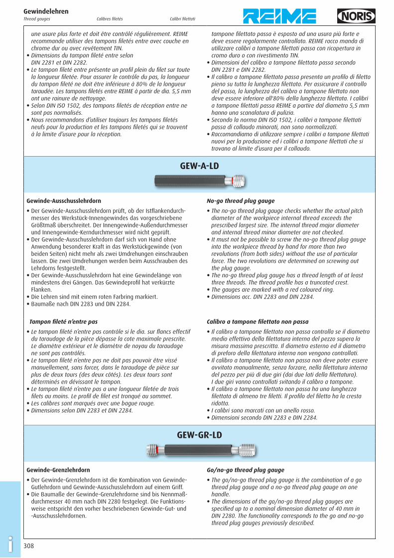
GEW-A-LD
Gewinde-Ausschusslehrdorn
E Der Gewinde-Ausschusslehrdorn prüft, ob der Istfl ankendurch-messer des Werkstück-Innen gewindes das vorgeschriebene Größtmaß über schreitet. Der Innengewinde-Außendurchmesser und Innengewinde-Kerndurchmesser wird nicht geprüft.
E Der Gewinde-Ausschusslehrdorn darf sich von Hand ohne Anwendung besonderer Kraft in das Werkstückgewinde (von beiden Seiten) nicht mehr als zwei Umdrehungen einschrauben lassen. Die zwei Umdrehungen werden beim Ausschrauben des Lehrdorns festgestellt.
E Der Gewinde-Ausschusslehrdorn hat eine Gewindelänge von mindestens drei Gängen. Das Gewindeprofi l hat verkürzte Flanken.
E Die Lehren sind mit einem roten Farbring markiert. E Baumaße nach DIN 2283 und DIN 2284.
No-go thread plug gauge
E The no-go thread plug gauge checks whether the actual pitch diameter of the workpiece internal thread exceeds the prescribed largest size. The internal thread major diameter and internal thread minor diameter are not checked.
E It must not be possible to screw the no-go thread plug gauge into the workpiece thread by hand for more than two revolutions (from both sides) without the use of particular force. The two revolutions are determined on screwing out the plug gauge.
E The no-go thread plug gauge has a thread length of at least three threads. The thread profi le has a truncated crest.
E The gauges are marked with a red coloured ring.E Dimensions acc. DIN 2283 and DIN 2284.
Tampon fi leté n’entre pas
E Le tampon fi leté n’entre pas contrôle si le dia. sur fl ancs effectif du taraudage de la pièce dépasse la cote maximale prescrite. Le diamètre extérieur et le diamètre de noyau du taraudage ne sont pas contrôlés.
E Le tampon fi leté n’entre pas ne doit pas pouvoir être vissé manuellement, sans forcer, dans le taraudage de pièce sur plus de deux tours (des deux côtés). Les deux tours sont déterminés en dévissant le tampon.
E Le tampon fi leté n’entre pas a une longueur fi letée de trois fi lets au moins. Le profi l de fi let est tronqué au sommet.
E Les calibres sont marqués avec une bague rouge.E Dimensions selon DIN 2283 et DIN 2284.
Calibro a tampone fi lettato non passa
E Il calibro a tampone fi lettato non passa controlla se il diametro medio effettivo della fi lettatura interna del pezzo supera la misura massima prescritta. Il diametro esterno ed il diametro di preforo della fi lettatura interna non vengono controllati.
E Il calibro a tampone fi lettato non passa non deve poter essere avvitato manualmente, senza forzare, nella fi lettatura interna del pezzo per più di due giri (dai due lati della fi lettatura). I due giri vanno controllati svitando il calibro a tampone.
E Il calibro a tampone fi lettato non passa ha una lunghezza fi lettata di almeno tre fi letti. Il profi lo del fi letto ha la cresta ridotta.
E I calibri sono marcati con un anello rosso.E Dimensioni secondo DIN 2283 e DIN 2284.
GEW-GR-LD
Gewinde-Grenzlehrdorn
E Der Gewinde-Grenzlehrdorn ist die Kombination von Gewinde-Gutlehrdorn und Gewinde-Ausschuss lehrdorn auf einem Griff.
E Die Baumaße der Gewinde-Grenzlehrdorne sind bis Nennmaß-durchmesser 40 mm nach DIN 2280 festgelegt. Die Funktions-weise ent spricht den vorher beschriebenen Gewinde-Gut- und -Ausschuss lehrdornen.
Go/no-go thread plug gauge
E The go/no-go thread plug gauge is the combination of a go thread plug gauge and a no-go thread plug gauge on one handle.
E The dimensions of the go/no-go thread plug gauges are specifi ed up to a nominal dimension diameter of 40 mm in DIN 2280. The functionality corresponds to the go and no-go thread plug gauges previously described.
GewindelehrenThread gauges Calibres fi letés Calibri fi lettati
309 i
Tampon fi leté entre/n’entre pas
E Le tampon fi leté entre/n’entre pas est la combinaison d’un tampon fi leté entre et d’un tampon fi leté n’entre pas sur une poignée.
E Les dimensions du tampon fi leté entre/n’entre pas sont défi nies jusqu’au diamètre nominal 40 mm selon DIN 2280. La fonction correspond à celle des tampons fi letés entre et n’entre pas décrits auparavant.
Calibro a tampone fi lettato passa/non passa
E Il calibro a tampone fi lettato passa/non passa è la combinazione di un calibro a tampone fi lettato passa e di un calibro a tampone fi lettato non passa su un’unica impugnatura.
E Le dimensioni del calibro a tampone fi lettato passa/non passa sono defi nite fi no al diametro nominale 40 mm dalla norma DIN 2280. La funzione corrisponde a quella dei calibri a tampone fi lettati passa e non passa descritti sopra.
Gewindelehren für Außengewinde
Für die Lehrung des Außengewindes zur Gutseite wird ein Gewinde-Gutlehrring verwendet, zur Ausschussseite ein Gewinde-Ausschusslehrring. Die Gewinde-Lehrringe sollen mit Gewinde- Abnutzungs-Prüfdornen regelmäßig überwacht werden. Zur Prüfung, insbesondere von neuen Lehrringen, werden Gut- und Ausschuss-Prüfdorne (Gegenlehrdorne) verwendet. Der Gewinde-Außendurchmesser d wird mit glatten Gut- und Ausschusslehr-ringen oder Gut- und Ausschuss-Rachenlehren geprüft.
Thread gauges for external threads
A go thread ring gauge is used for gauging the external thread for the go side, a no-go thread ring gauge for the no-go side. The thread ring gauges should be monitored regularly with thread wear check plug gauges. Check go and no-go plug gauges (check plug gauges) are used for testing, especially with new ring gauges. The major diameter of thread d is tested with smooth go and no-go ring gauges or go and no-go snap gauges.
Calibres fi letés pour fi lets extérieurs
Pour le contrôle de fi lets extérieurs, la bague fi letée entre est utilisée pour le côté entre et la bague fi letée n’entre pas pour le côté n’entre pas. Les bagues fi letées doivent être contrôlées régulièrement avec des tampons fi letés vérifi cateurs d’usure. Les tampons de contrôle entre et n’entre pas (tampons de vérifi cation) sont utilisés pour le contrôle, en particulier de bagues neuves. Le diamètre extérieur du fi let est contrôlé au moyen de bagues lisses entre et n’entre pas ou au moyen de calibres-mâchoires entre et n’entre pas.
Calibri fi lettati per fi lettature esterne
Per il controllo di fi lettature esterne, il calibro ad anello fi lettato passa è utilizzato per il lato passa ed il calibro ad anello fi lettato non passa per il lato non passa. I calibri ad anello fi lettati devono essere controllati regolarmente con calibri a tampone fi lettati per controllo d’usura. I calibri a tampone di controllo passa e non passa (calibri a tampone di riscontro) sono utilizzati per il controllo, in particolare di calibri ad anello nuovi. Il diametro esterno del fi letto è controllato per mezzo di calibri ad anello lisci passa e non passa oppure per mezzo di calibri a forcella passa e non passa.
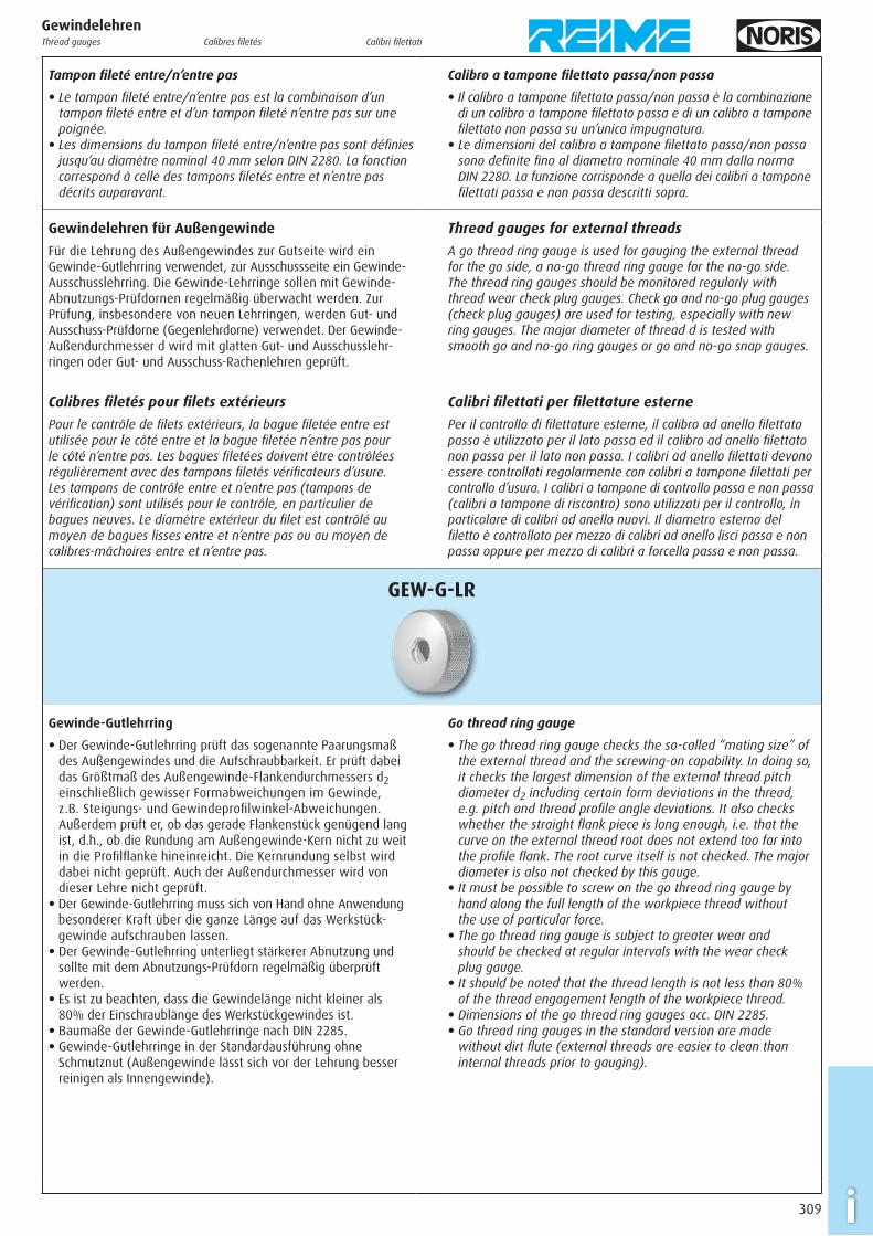
GEW-G-LR
Gewinde-Gutlehrring
E Der Gewinde-Gutlehrring prüft das sogenannte Paarungsmaß des Außengewindes und die Auf schraubbarkeit. Er prüft dabei das Größtmaß des Außengewinde-Flankendurchmessers d2 einschließlich gewisser Formabweichungen im Gewinde, z.B. Steigungs- und Gewindeprofi l winkel-Abweichungen. Außerdem prüft er, ob das gerade Flankenstück genügend lang ist, d.h., ob die Rundung am Außengewinde-Kern nicht zu weit in die Profi lfl anke hineinreicht. Die Kernrundung selbst wird dabei nicht geprüft. Auch der Außendurchmesser wird von dieser Lehre nicht geprüft.
E Der Gewinde-Gutlehrring muss sich von Hand ohne Anwendung besonderer Kraft über die ganze Länge auf das Werkstück-gewinde auf schrauben lassen.
E Der Gewinde-Gutlehrring unterliegt stärkerer Abnutzung und sollte mit dem Abnutzungs-Prüfdorn regelmäßig überprüft werden.
E Es ist zu beachten, dass die Gewindelänge nicht kleiner als 80% der Einschraublänge des Werk stück gewindes ist.
E Baumaße der Gewinde-Gutlehrringe nach DIN 2285.E Gewinde-Gutlehrringe in der Standardausführung ohne
Schmutznut (Außengewinde lässt sich vor der Lehrung besser reinigen als Innengewinde).
Go thread ring gauge
E The go thread ring gauge checks the so-called “mating size” of the external thread and the screwing-on capability. In doing so, it checks the largest dimension of the external thread pitch diameter d2 including certain form deviations in the thread, e.g. pitch and thread profi le angle deviations. It also checks whether the straight fl ank piece is long enough, i.e. that the curve on the external thread root does not extend too far into the profi le fl ank. The root curve itself is not checked. The major diameter is also not checked by this gauge.
E It must be possible to screw on the go thread ring gauge by hand along the full length of the workpiece thread without the use of particular force.
E The go thread ring gauge is subject to greater wear and should be checked at regular intervals with the wear check plug gauge.
E It should be noted that the thread length is not less than 80% of the thread engagement length of the workpiece thread.
E Dimensions of the go thread ring gauges acc. DIN 2285.E Go thread ring gauges in the standard version are made
without dirt fl ute (external threads are easier to clean than internal threads prior to gauging).
GewindelehrenThread gauges Calibres fi letés Calibri fi lettati
310i
GewindelehrenThread gauges Calibres fi letés Calibri fi lettati
Bague fi letée entre
E La bague fi letée entre contrôle ce que l’on nomme la cote d’appariement du fi let extérieur et la possibilité de visser la bague. Elle contrôle la cote maximale du diamètre sur fl ancs du fi letage extérieur d2, y compris certaines déviations de forme dans le fi let, p. ex. des déviations du pas et de l’angle de profi l du fi let. De plus, la bague contrôle si la partie de fl anc qui est droite est suffi samment longue, c’est-à-dire si le rayon du noyau du fi let extérieur ne passe pas trop loin dans le fl anc du profi l. Par contre le rayon du noyau n’est pas contrôlé. De même le dia. extérieur n’est pas contrôle par ce calibre.
E La bague fi letée entre doit pouvoir se visser manuellement sur toute la longueur du fi letage de la pièce sans forcer.
E La bague fi letée entre est exposée à une usure plus forte et doit être contrôlée régulièrement au moyen du tampon vérifi cateur d’usure.
E Il faut noter que pour assurer le contrôle du pas, la longueur fi letée de la bague ne doit pas être inférieure à 80% de la longueur du fi letage de la pièce.
E Dimensions des bagues fi letées entre selon DIN 2285.E Les bagues fi letées entre en version standard sont sans rainure
de nettoyage (il est plus facile nettoyer un fi letage extérieur avant le contrôle qu’un taraudage).
Calibro ad anello fi lettato passa
E Il calibro ad anello fi lettato passa controlla la cosiddetta misura d’accoppiamento della fi lettatura esterna e la possibilità d’avvitamento del calibro ad anello. Controlla la misura massima del diametro medio della fi lettatura esterna d2, comprese certe deviazioni di forma nella fi lettatura, p. es. deviazioni del passo e dell’angolo di profi lo del fi letto. Inoltre il calibro ad anello con-trolla se la parte diritta del fi anco è suffi cientemente lunga, cioè se il raggio del nocciolo della fi lettatura esterna non passa troppo oltre nel fi anco del profi lo. Il raggio del nocciolo invece non è controllato. Anche il diametro esterno non è controllato da questo calibro.
E Il calibro ad anello fi lettato passa deve poter essere avvitato manualmente su tutta la lunghezza della fi lettatura del pezzo senza forzare.
E Il calibro ad anello fi lettato passa è esposto ad una usura più forte e deve essere controllato regolarmente per mezzo del calibro a tampone per controllo d’usura.
E Bisogna notare che per assicurare il controllo del passo, la lunghezza fi lettata del calibro ad anello non deve essere inferiore all’80% della lunghezza fi lettata del pezzo.
E Dimensioni dei calibri ad anello fi lettati passa secondo DIN 2285.E I calibri ad anello fi lettati passa in versione standard sono senza
scanalatura di pulizia (è più facile pulire una fi lettatura esterna prima del controllo che una fi lettatura interna).
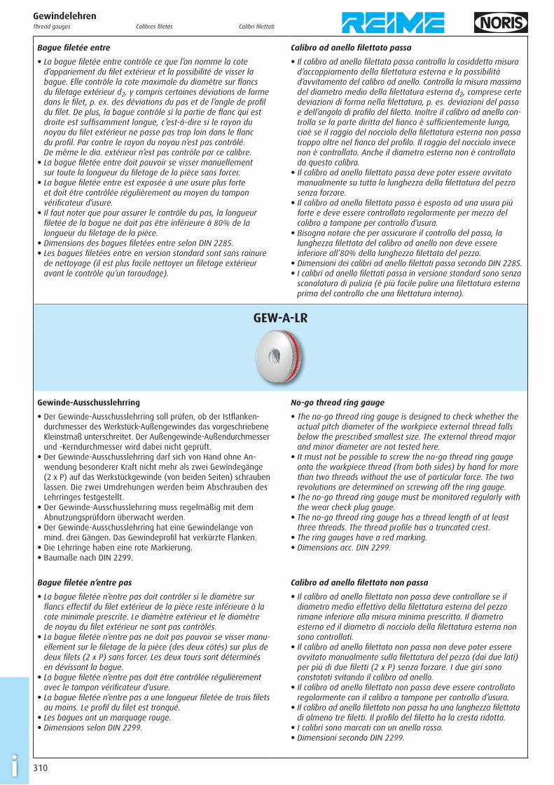
GEW-A-LR
Gewinde-Ausschusslehrring
E Der Gewinde-Ausschusslehrring soll prüfen, ob der Istfl anken-durchmesser des Werkstück-Außengewindes das vorgeschriebene Kleinstmaß unter schreitet. Der Außengewinde-Außendurchmesser und -Kerndurchmesser wird dabei nicht geprüft.
E Der Gewinde-Ausschusslehrring darf sich von Hand ohne An-wendung besonderer Kraft nicht mehr als zwei Gewindegänge (2 x P) auf das Werkstückgewinde (von beiden Seiten) schrauben lassen. Die zwei Umdrehungen werden beim Abschrauben des Lehrringes festgestellt.
E Der Gewinde-Ausschusslehrring muss regelmäßig mit dem Abnutzungsprüfdorn überwacht werden.
E Der Gewinde-Ausschusslehrring hat eine Gewindelänge von mind. drei Gängen. Das Gewindeprofi l hat verkürzte Flanken.
E Die Lehrringe haben eine rote Markierung.E Baumaße nach DIN 2299.
No-go thread ring gauge
E The no-go thread ring gauge is designed to check whether the actual pitch diameter of the workpiece external thread falls below the prescribed smallest size. The external thread major and minor diameter are not tested here.
E It must not be possible to screw the no-go thread ring gauge onto the workpiece thread (from both sides) by hand for more than two threads without the use of particular force. The two revolutions are determined on screwing off the ring gauge.
E The no-go thread ring gauge must be monitored regularly with the wear check plug gauge.
E The no-go thread ring gauge has a thread length of at least three threads. The thread profi le has a truncated crest.
E The ring gauges have a red marking.E Dimensions acc. DIN 2299.
Bague fi letée n’entre pas
E La bague fi letée n’entre pas doit contrôler si le diamètre sur fl ancs effectif du fi let extérieur de la pièce reste inférieure à la cote minimale prescrite. Le diamètre extérieur et le diamètre de noyau du fi let extérieur ne sont pas contrôlés.
E La bague fi letée n’entre pas ne doit pas pouvoir se visser manu-ellement sur le fi letage de la pièce (des deux côtés) sur plus de deux fi lets (2 x P) sans forcer. Les deux tours sont déterminés en dévissant la bague.
E La bague fi letée n’entre pas doit être contrôlée régulièrement avec le tampon vérifi cateur d’usure.
E La bague fi letée n’entre pas a une longueur fi letée de trois fi lets au moins. Le profi l du fi let est tronqué.
E Les bagues ont un marquage rouge.E Dimensions selon DIN 2299.
Calibro ad anello fi lettato non passa
E Il calibro ad anello fi lettato non passa deve controllare se il diametro medio effettivo della fi lettatura esterna del pezzo rimane inferiore alla misura minima prescritta. Il diametro esterno ed il diametro di nocciolo della fi lettatura esterna non sono controllati.
E Il calibro ad anello fi lettato non passa non deve poter essere avvitato manualmente sulla fi lettatura del pezzo (dai due lati) per più di due fi letti (2 x P) senza forzare. I due giri sono constatati svitando il calibro ad anello.
E Il calibro ad anello fi lettato non passa deve essere controllato regolarmente con il calibro a tampone per controllo d’usura.
E Il calibro ad anello fi lettato non passa ha una lunghezza fi lettata di almeno tre fi letti. Il profi lo del fi letto ha la cresta ridotta.
E I calibri sono marcati con un anello rosso.E Dimensioni secondo DIN 2299.