
AMO GmbH Absolutsysteme nach dem induktiven AMOSIN...
36
AMO GmbH Absolutsysteme nach dem induktiven AMOSIN ® – Messprinzip Absolute encoder based on the AMOSIN ® – Inductive Measuring Principle
Transcript of AMO GmbH Absolutsysteme nach dem induktiven AMOSIN...

AMO GmbH
Absolutsysteme nach dem induktiven AMOSIN® – MessprinzipAbsolute encoder based on the AMOSIN® – Inductive Measuring Principle

2
Dieses Dokument wurde mit größter Sorgfalt erstellt. Sollte es zu technischen Änderungen kommen, werden diese unver-züglich in den Dokumenten auf unserer Homepage www.amo-gmbh.com aktualisert.
Mit Erscheinen dieses Kataloges verlieren alle vorherigen Ausgaben ihre Gültigkeit.
Den aktuell gültigen Katalog finden Sie auf unserer Home-page www.amo-gmbh.com
SN: ABSOLUTE-P 20150706
This document was created very carefully. If there are any technical changes, they will promptly updated in the docu-ments on our website www.amo-gmbh.com
With the publication of this brochure all previous editions become invalid.
The currently valid brochure is available on our website www.amo-gmbh.com

3
InhaltsübersichtTable of contents
Allgemeine InformationenGeneral informations
Allgemeines General information .............................................................................................. 4
Absolute WinkelmesssystemeAbsolute angle measuring systems
Standard Messflansche für Außenabtastung Standardmeasuringflangesforoutsidescanning ................................................ 6
Kundenspezifische Messflansche für Außenabtastung Customerspecificmeasuringflangesforoutsidescanning .................................. 8
Messringe für Außenabtastung Measuring rings for outside scanning ................................................................... 10
Messringe für Innenabtastung Measuring rings for inside scanning ..................................................................... 12
Abtastkopf für absolute Winkelmesssysteme Scanning head for absolute angle measuring systems ........................................ 14
Nicht geführte Absolute LängenmesssystemeNon guided Absolute length measuring systems
Maßbänder für nicht geführte Messsysteme, geklebt Scales for non-guided measuring systems, mounted with adhesive tape ............ 18
Maßbänder für nicht geführte Messsysteme mit Stahlträger Scales for non-guided measuring systems with steel carrier ................................ 19
Abtastkopf für nicht geführte Systeme Scanning heads for non-guided measuring systems ............................................ 22
Geführte Absolute LängenmesssystemeGuided Absolute length measuring systems
Messschiene für geführte Systeme Measuring rail for guided systems ........................................................................ 24
Abtastkopf für geführte Systeme Scanning head for guided systems ....................................................................... 27
Allgemeine technische DatenGeneral technical data
Maximale Drehzahlen Maximum speeds .................................................................................................. 31
Kabel Cable .................................................................................................................... 32
Steckerbelegungen Plug and connection assignments ........................................................................ 33
4
Absolute MesssystemeAbsolute measuring systems
Allgemeine InformationenGeneral informations
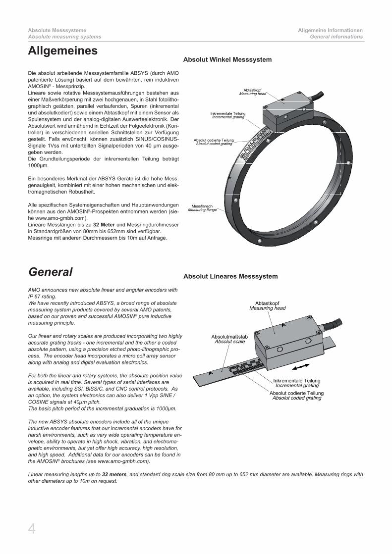
AllgemeinesDie absolut arbeitende Messsystemfamilie ABSYS (durch AMO patentierte Lösung) basiert auf dem bewährten, rein induktiven AMOSIN® - Messprinzip.Lineare sowie rotative Messsystemausführungen bestehen aus einer Maßverkörperung mit zwei hochgenauen, in Stahl fotolitho-graphisch geätzten, parallel verlaufenden, Spuren (inkremental und absolutkodiert) sowie einem Abtastkopf mit einem Sensor als Spulensystem und der analog-digitalen Auswerteelektronik. Der Absolutwert wird annähernd in Echtzeit der Folgeelektronik (Kon-troller) in verschiedenen seriellen Schnittstellen zur Verfügung gestellt. Falls erwünscht, können zusätzlich SINUS/COSINUS-Signale 1Vss mit unterteilten Signalperioden von 40 µm ausge-geben werden.Die Grundteilungsperiode der inkrementellen Teilung beträgt 1000µm.
Ein besonderes Merkmal der ABSYS-Geräte ist die hohe Mess-genauigkeit, kombiniert mit einer hohen mechanischen und elek-tromagnetischen Robustheit.
Alle spezifischen Systemeigenschaften und Hauptanwendungen können aus den AMOSIN®-Prospekten entnommen werden (sie-he www.amo-gmbh.com).Lineare Messlängen bis zu 32 Meter und Messringdurchmesser in Standardgrößen von 80mm bis 652mm sind verfügbar.Messringe mit anderen Durchmessern bis 10m auf Anfrage.
GeneralAMO announces new absolute linear and angular encoders with IP 67 rating. We have recently introduced ABSYS, a broad range of absolute measuring system products covered by several AMO patents, based on our proven and successful AMOSIN® pure inductive measuring principle.
Our linear and rotary scales are produced incorporating two highly accurate grating tracks - one incremental and the other a coded absolute pattern, using a precision etched photo-lithographic pro-cess. The encoder head incorporates a micro coil array sensor along with analog and digital evaluation electronics.
For both the linear and rotary systems, the absolute position value is acquired in real time. Several types of serial interfaces are available, including SSI, BiSS/C, and CNC control protocols. As an option, the system electronics can also deliver 1 Vpp SINE / COSINE signals at 40µm pitch.Thebasicpitchperiodoftheincrementalgraduationis1000μm.
The new ABSYS absolute encoders include all of the unique inductive encoder features that our incremental encoders have for harsh environments, such as very wide operating temperature en-velope, ability to operate in high shock, vibration, and electroma-gnetic environments, but yet offer high accuracy, high resolution, and high speed. Additional data for our encoders can be found in the AMOSIN® brochures (see www.amo-gmbh.com).
Linear measuring lengths up to 32 meters, and standard ring scale size from 80 mm up to 652 mm diameter are available. Measuring rings with other diameters up to 10m on request.
AbtastkopfMeasuring head
Inkrementale TeilungIncremental grating
Absolut codierte TeilungAbsolut coded grating
MessflanschMeasuring flange
Absolut codierte TeilungAbsolut coded grating
Inkrementale TeilungIncremental grating
AbtastkopfMeasuring head
AbsolutmaßstabAbsolut scale
Absolut Winkel Messsystem
Absolut Lineares Messsystem
5
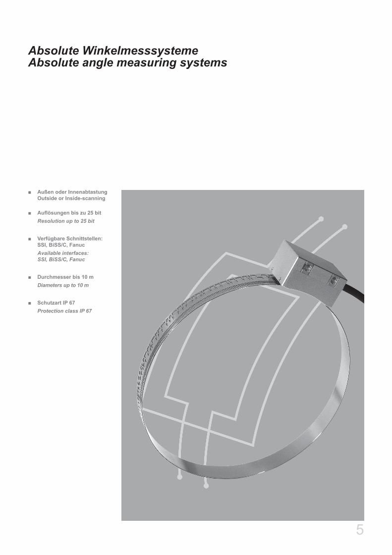
Absolute WinkelmesssystemeAbsolute angle measuring systems
Außen oder Innenabtastung ■Outside or Inside-scanning
Auflösungen bis zu 25 bit ■Resolution up to 25 bit
Verfügbare Schnittstellen: ■SSI, BiSS/C, FanucAvailable interfaces: SSI, BiSS/C, Fanuc
Durchmesser bis 10 m ■Diameters up to 10 m
Schutzart IP 67 ■Protection class IP 67

6
Absolute WinkelmesssystemeAbsolute angle measuring systems
Messflansche und Messringe - AußenabtastungMeasuring flanges and rings - outside scanning
Standard Messflansche und Messringe für AußenabtastungStandard measuring flanges and rings for outside scanning
Messflansche WMFA-1010 mit 1000µm Teilungsperiode werden als Standardgrößen laut untenstehender Tabelle geliefert.Kundenspezifische Ausführungen der Messflansche können komplett mit montierem Maßband geliefert werden oder es wird der Messflansch kundenseitig beigestellt und AMO montiert den Maßbandring (näheres siehe Seite 8).Die Maßverkörperung der absoluten Winkelmesssysteme mit Außen-abtastung kann in folgenden Ausführungen realisiert werden:
Standard Messflansche ■kundenspezifische Messflansche ■Messringe ■
MeasuringflangesWMFA-1010 with 1000µm grating pitch offered as standard sizes as shown in the table below.Customerspecificdesigns for themeasuringflangecanbesuppliedbyAMOorthemeasuringflangewillbesuppliedbythecustomerformounting the measuring ring at AMO (see page 8 for details).
The measurement scale of the absolute angle measuring systems with external scan can be realized in the following models:
standardmeasuringflange ■customerspecificflange ■measuring rings ■
Teilstriche / Umdrehung (N)Grating pitches / revolution (N)
Innendurchmesser ØI (siehe Zeichnung)Inner diameter ØI (see drawing)
0 .......... klein / small1 .......... groß / large
LinearitätsfehlerLinearity error
0 ... ± 10 µm arc length 1 ... ± 5 µm arc length 2 ... ± 3 µm arc length
WMFA-1010. - -
Technische DatenTechnical data
Bestellcode: WMFA-1010Ordering code: WMFA-1010
WMFA-1010
Standardgrößen N / Standard sizes N
0256 0360 0512 0720 0900 1024Teilungsperiode [Bogenlänge]:
Grating pitch [arc length]: 1000 µm
Teilungsgenauigkeit [Bogenlänge]:Grating accuracy [arc length]: ± 10 µm, ± 5 µm oder (or) ± 3 µm
Mechanische Ausführung:Mechanical execution:
Rostfreier Messflansch in 2 Ausführungen:Stainlesssteelmeasuringflangein2versions:
massiv/massive: WMFA-1010.x-xxxx-0dünn/thin: WMFA-1010.x-xxxx-1
Außendurchmesser ØA [mm]:Outer diameter ØA [mm]: 81,95 115,12 163,54 229,78 287,08 326,55
Inkrementelle Teilstriche / U:Incremetal grating pitches / rev: 256 360 512 720 900 1024
Absolute Auflösung / U [Inkremente] 1µm:Absolute resolution / rev [increments] 1µm: 218 360 x 210 219 720 x 210 900 x 210 220
Absolute Auflösung / U [Inkremente] 0,25µm:Absolute resolution / rev [increments] 0,25µm: 220 360 x 212 221 720 x 212 900 x 212 222

7
Messflansche und Messringe - AußenabtastungMeasuring flanges and rings - outside scanning
Absolute WinkelmesssystemeAbsolute angle measuring systems
Abmessungen StandardmessflanscheDimensions standard measuring flanges
TypeWMFA-1010
Ø A[mm]
Ø I[mm]
Ø B[mm] β
2) TeilungsgenauigkeitScale accuracy
WMFA-1010.0 WMFA-1010.1 WMFA-1010.20256-1 81,95 60 +0
-0,01 70 6 x 60° ±50” ±25” ±15“
0360-0 115,12 60 +0-0,01 75
6 x 60° ±36” ±18” ±10“0360-1 115,12 95 +0
-0,01 105
0512-0 163,54 105 +0-0,01 120
6 x 60° ±24” ±12” ±7,5“ 0512-1 1) 163,54 143 +0
-0,01 153
0720-0 229,78 180 +0-0,01 195
6 x 60° ±18” ±9” ±5,4“ 0720-1 1) 229,78 209 +0
-0,01 219
0900-0 287,08 180 +0-0,01 195
12 x 30° ±14” ±7” ±4,3“ 0900-1 1) 287,08 266 +0
-0,01 276
1024-0 326,55 220 +0-0,01 235
12 x 30° ±12” ±6” ±3,8“ 1024-1 1) 326,55 296 +0
-0,01 311
1) Nur für Presspassung auf Kundenwelle (Toleranzempfehlung +0,02 / +0,01)Onlyforpress-fittassemblyonthecustomersshaft(recommendedshafttolerance+0,02/+0,01)2) Die Teilungsgenauigkeit aller AMO Winkelmesssysteme kann durch Zusatzgeräte oder Kompensationsverfahren um ein Vielfaches erhöht werden. Kontaktieren Sie Ihre AMO Vertretung. The grating accuracy of all AMO Angle Measuring Systems may be increased dramatically by additional Equipmend or Compensating processes. Please contact your AMO Distributor
Abmessungen WMFA-1010Dimensions WMFA-1010
ß
M6
0,1
X
ØB
0,00
5
15 ±0,05
5,2
0,1
0,5x
45°
0,5x
45°
6,5 6,5
2 0+0,5
DETAIL X M 2:1
ØA
0,00
5A
0,00
5
A
ØI 0 -0
,01 +0
,1 0

8
Absolute WinkelmesssystemeAbsolute angle measuring systems
Messflansche und Messringe - AußenabtastungMeasuring flanges and rings - outside scanning
Kundenspezifische Ausführungen der Messflansche können komplett mit montierem Maßband geliefert werden (Typ WMFA) oder es wird der Messflansch kundenseitig beigestellt und AMO montiert den Maß-bandring (Typ WMBA). In diesem Fall kann der Durchmesser für die Montage des Maßbandes lt. Tabelle auf der nächsten Seite berechnet werden.Sondergrößen mit beliebiger Strichzahl sind auf Anfrage erhältlich.
CustomerspecificdesignsforthemeasuringflangecanbesuppliedbyAMO (Type WMFA)orthemeasuringflangewillbesuppliedbythecus-tomer for mounting the measuring ring at AMO (Type WMBA). In this case the diameter for mounting the measuring ring can be calculated as shown in the table on the next page.Special sizes with any number of pitches per revolution on request
Kundenspezifische Messflansche für AußenabtastungCustomer specific measuring flanges for outside scanning
Für die Fertigungszeichnung des Trägerflansches kann eine Freigabe durch AMO herangezogen werden.
Bei Anwendungen mit großen Durchmessern und bedeutenden Tem-peraturschwankungen im Betrieb muss das Systemdesign entspre-chend ausgelegt werden.
TheproductiondrawingforthecarrierflangecanbereleasedbyAMO.
Forapplicationswithlargediametersorsignificantvariationsintem-perature during operation the system must be designed accordingly.
WMFA-1010 / WMBA-1010
Standardgrößen N / Standard sizes N
0256 0360 0512 0720 0900 1024Teilungsperiode [Bogenlänge]:
Grating pitch [arc length]: 1000 µm
Teilungsgenauigkeit [Bogenlänge]:Grating accuracy [arc length]: ± 10 µm, ± 5 µm oder (or) ± 3 µm
Mechanische Ausführung:Mechanical execution:
Kundenspezifisch, empfohlenes Material 1.4104 (X14CrMoS17) oder 1.7225 (42CrMo4) Customerspecific,recommendedmaterial1.4104(Aisi430F)or1.7225(Aisi4140)
Außendurchmesser ØA [mm]:Outer diameter ØA [mm]: 81,95 115,12 163,54 229,78 287,08 326,55
Inkrementelle Teilstriche / U:Incremetal grating pitches / rev: 256 360 512 720 900 1024
Absolute Auflösung / U [Inkremente] 1µm:Absolute resolution / rev [increments] 1µm: 218 360 x 210 219 720 x 210 900 x 210 220
Absolute Auflösung / U [Inkremente] 0,25µm:Absolute resolution / rev [increments] 0,25µm: 220 360 x 212 221 720 x 212 900 x 212 222
Technische DatenTechnical data
9
Messflansche und Messringe - AußenabtastungMeasuring flanges and rings - outside scanning
Absolute WinkelmesssystemeAbsolute angle measuring systems
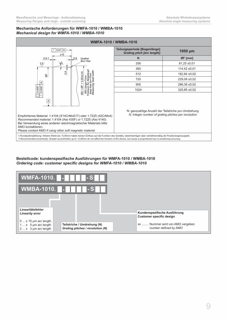
Mechanische Anforderungen für WMFA-1010 / WMBA-1010Mechanical design for WMFA-1010 / WMBA-1010
WMFA-1010 / WMBA-1010
0,5-1
15°
>150,8
0,5
ØS
= Ø
F +
0,65
±0,0
5
ØS
Län
ge>7
mm
Frei
raum
für A
btas
tkop
f k
eep
free
for>
7mm
Mea
surin
g he
ad w
idth
GratfreiBurr free
0,00
5*0,
005*
A
0,01 A
A
l
ØF
3,2
Empfohlenes Material: 1.4104 (X14CrMoS17) oder 1.7225 (42CrMo4) Recommended material: 1.4104 (Aisi 430F) or 1.7225 (Aisi 4140)Bei Verwendung eines anderen weichmagnetischer Materials bitte AMO kontaktieren.Please contact AMO if using other soft magnetic material.
Teilungsperiode [Bogenlänge]:Grating pitch [arc length]: 1000 µm
N ØF [mm]256 81,25 ±0,01
360 114,42 ±0,01
512 162,84 ±0,02
720 229,08 ±0,02
900 286,38 ±0,02
1024 325,85 ±0,02
N: ganzzahlige Anzahl der Teilstriche pro UmdrehungN: Integer number of grating pitches per revolution
*) Rundlaufempfehlung: Höhere Werte bis ~0,05mm haben keinen Einfluss auf die Funktion des Gerätes, beeinträchtigen aber verhältnismäßig die Positioniergenauigkeit.*) Recommended eccentricity: Greater eccentricities up to ~0,05mm do not affect the function of the device, but cause a proportional loss in positioning accuracy.
Bestellcode: kundenspezifische Ausführungen für WMFA-1010 / WMBA-1010Ordering code: customer specific designs for WMFA-1010 / WMBA-1010
Kundenspezifische Ausführung Customer specific design
xx ........ Nummer wird von AMO vergeben numberdefinedbyAMO
Teilstriche / Umdrehung (N)Grating pitches / revolution (N)
LinearitätsfehlerLinearity error
0 ... ± 10 µm arc length 1 ... ± 5 µm arc length 2 ... ± 3 µm arc length
WMFA-1010. S- -
WMBA-1010. S- -

10
Absolute WinkelmesssystemeAbsolute angle measuring systems
Messflansche und Messringe - AußenabtastungMeasuring flanges and rings - outside scanning
Messringe für AußenabtastungMeasuring rings for outside scanning
Dünner, nichtrostender Messring, bestehend aus Stahlträgerring, Maß-bandring und Abdeckring, welcher mit leichter Presspassung auf dem kundenspezifischen Flansch aufgezogen wird. (siehe Montageanlei-tungen auf www.amo-gmbh.com) Für Sonderanwendungen kann der Messring auch werksseitig auf den Flansch montiert werden, auch Kreissegmente sind möglich.
Thin, stainless steel measuring ring, consisting of a steel carrier ring, agraduationringandaprotectionring.Easilypressfittedmountingtothecorrespondingflangebythecustomer.(seemountinginstructionatwww.amo-gmbh.com) For special applications the measuring ring (circular segment also pos-sible)canbemountedonaflangeatthefactory.
WMRA-1010
14
0,65
F
AInnendurchmesserInner diameter
AußendurchmesserOuter diameter
Sondergrößen mit beliebiger Strichzahl auf AnfrageSpecial sizes with any number of pitches per revolution on request
WMRA-1010
Standardgrößen N / Standard sizes N
0256 0360 0512 0720 0900 1024 1440 1800 2048Teilungsperiode [Bogenlänge]:
Grating pitch [arc length]: 1000 µm
Teilungsgenauigkeit [Bogenlänge]:Grating accuracy [arc length]: ± 10 µm, ± 5 µm oder (or) ± 3 µm
Mechanische Ausführung:Mechanical execution:
Rostfreier MaßbandringStainless steel measuring ring
Flanschmaterial:Flange material:
Kein spezielles Material erforderlichNo special material required
Außendurchmesser ØA [mm]:Outer diameter ØA [mm]: 81,95 115,12 163,54 229,78 287,08 326,55 458,99 573,61 652,58
Inkrementelle Teilstriche / U:Incremetal grating pitches / rev: 256 360 512 720 900 1024 1440 1800 2048
Absolute Auflösung / U [Inkremente] 1µm:Absolute resolution / rev [increments] 1µm: 218 360 x
210 219 720 x 210
900 x 210 220 1440 x
2101800 x
210 221
Absolute Auflösung / U [Inkremente] 0,25µm:Absolute resolution / rev [increments] 0,25µm: 220 360 x
212 221 720 x 212
900 x 212 222 1440 x
2121800 x
212 223
Technische DatenTechnical data

11
Messflansche und Messringe - AußenabtastungMeasuring flanges and rings - outside scanning
Absolute WinkelmesssystemeAbsolute angle measuring systems
Mechanische Anforderungen für WMRA-1010Mechanical design for WMRA-1010
WMRA-1010
0,5-1
15°
>150,8
0,5
ØS
= Ø
F +
1,15
±0,0
5
ØS
Län
ge>7
mm
Frei
raum
für A
btas
tkop
f k
eep
free
for>
7mm
Mea
surin
g he
ad w
idth
GratfreiBurr free
0,00
5*0,
005*
A
0,01 A
A
l
ØF
3,2
Teilungsperiode [Bogenlänge]:Grating pitch [arc length]: 1000 µm
N ØF [mm]256 80,65 ±0,01
360 113,82 ±0,01
512 162,24 ±0,02
720 228,48 ±0,02
900 285,78 ±0,02
1024 325,25 ±0,02
1440 457,69 ±0,03
1800 572,31 ±0,06
2048 651,28 ±0,07
N: ganzzahlige Anzahl der Teilstriche pro UmdrehungN: Integer number of grating pitches per revolution
*) Rundlaufempfehlung: Höhere Werte bis ~0,05mm haben keinen Einfluss auf die Funktion des Gerätes, beeinträchtigen aber verhältnismäßig die Positioniergenauigkeit.*) Recommended eccentricity: Greater eccentricities up to ~0,05mm do not affect the function of the device, but cause a proportional loss in positioning accuracy.
Teilstriche / Umdrehung (N)Grating pitches / revolution (N)
LinearitätsfehlerLinearity error
0 ... ± 10 µm arc length 1 ... ± 5 µm arc length 2 ... ± 3 µm arc length
WMRA-1010. -
Bestellcode: WMRA-1010Ordering code: WMRA-1010
Für die Fertigungszeichnung des Trägerflansches kann eine Freigabe durch AMO herangezogen werden.
Bei Anwendungen mit großen Durchmessern und bedeutenden Temperaturschwankungen im Betrieb und dort wo keine Stahlträger-flansche eingesetzt werden, muss das Systemdesign entsprechend ausgelegt werden.
TheproductiondrawingforthecarrierflangecanbereleasedbyAMO.
Forapplicationswithlargediametersorsignificantvariationsintem-peratureduringoperationandwhenthecarrierflangesarenotmadeof steel, the system must be designed accordingly.

12
Absolute WinkelmesssystemeAbsolute angle measuring systems
Messringe - InnenabtastungMeasuring rings - inside scanning
Messringe für InnenabtastungMeasuring rings for inside scanning
Dünner, nichtrostender Messring WMRA-1110 bestehend aus Stahlträ-gerring und Maßbandring.Der Messring wird durch „Einklicken“ in eine entsprechende Nut bzw. an eine Anschlagschulter kundenseitig montiert.
Thin, stainless steel measuring ring WMRA-1110 consisting of a steel carrier ring and a graduation ring.The ring can be mounted over a „snap-effect“ by the customer into a corresponding groove or against a stop collar.
WMRA-1110
B
14
0,60
F
AußendurchmesserOuter diameter
InnendurchmesserInner diameter
Sondergrößen mit beliebiger Strichzahl auf AnfrageSpecial sizes with any number of pitches per revolution on request
WMRA-1110
Standardgrößen N / Standard sizes N
1024 1440 1800 2048Teilungsperiode [Bogenlänge]:
Grating pitch [arc length]: 1000 µm
Teilungsgenauigkeit [Bogenlänge]:Grating accuracy [arc length]: ± 10 µm, ± 5 µm oder (or) ± 3 µm
Mechanische Ausführung:Mechanical execution:
Rostfreier MaßbandringStainless steel measuring ring
Flanschmaterial:Flange material:
Kein spezielles Material erforderlichNo special material required
Inkrementelle Teilstriche / U:Incremetal grating pitches / rev: 1024 1440 1800 2048
Absolute Auflösung / U [Inkremente] 1µm:Absolute resolution / rev [increments] 1µm: 220 1440 x 210 1800 x 210 221
Absolute Auflösung / U [Inkremente] 0,25µm:Absolute resolution / rev [increments] 0,25µm: 222 1440 x 212 1800 x 212 223
Technische DatenTechnical data
13
Messringe - InnenabtastungMeasuring rings - inside scanning
Absolute WinkelmesssystemeAbsolute angle measuring systems
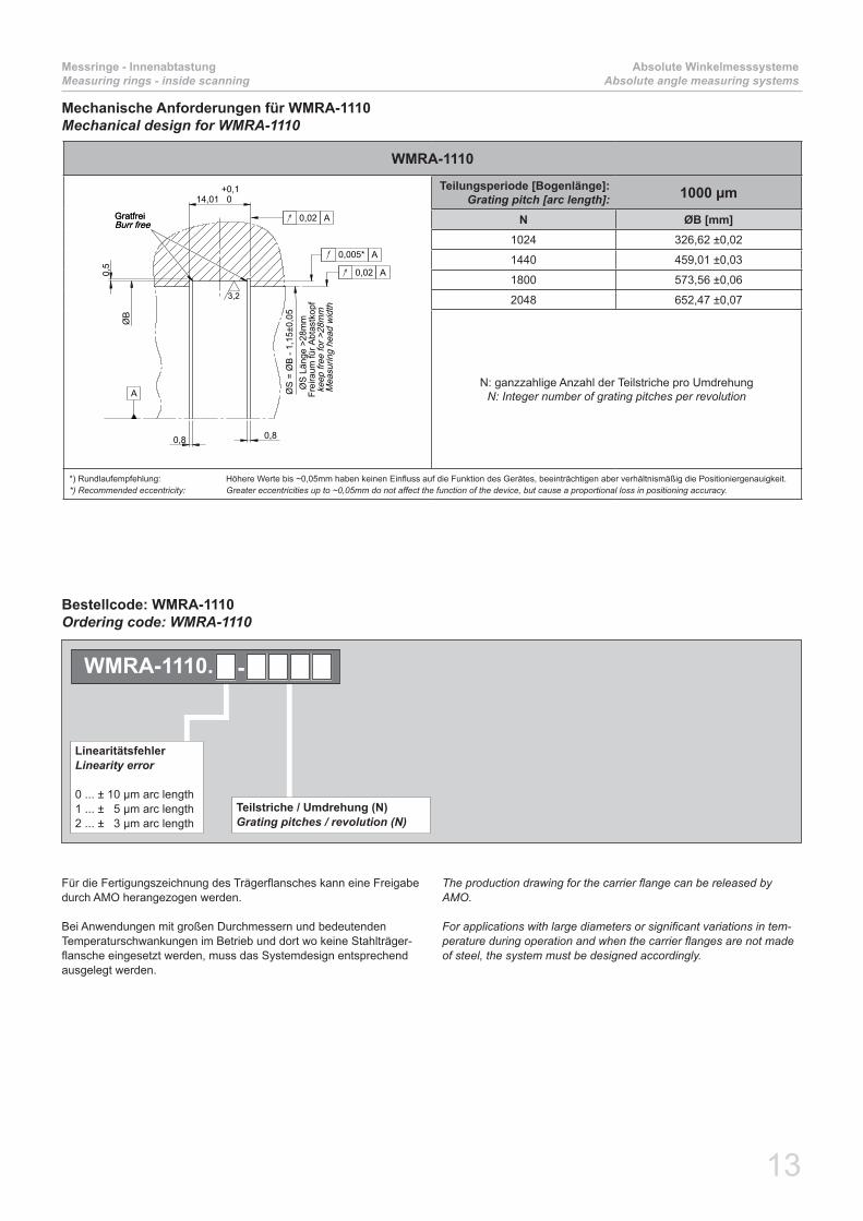
Mechanische Anforderungen für WMRA-1110Mechanical design for WMRA-1110
WMRA-1110
14,01 0+0,1
0,5
0,8 0,8
ØB
ØS
= Ø
B -
1,15
±0,0
5
GratfreiBurr freeGratfreiBurr free
3,2
0,02 A
0,005* A
0,02 A
A Ø
S L
änge
>28
mm
Frei
raum
für A
btas
tkop
f k
eep
free
for >
28m
m M
easu
ring
head
wid
th
Teilungsperiode [Bogenlänge]:Grating pitch [arc length]: 1000 µm
N ØB [mm]1024 326,62 ±0,02
1440 459,01 ±0,03
1800 573,56 ±0,06
2048 652,47 ±0,07
N: ganzzahlige Anzahl der Teilstriche pro UmdrehungN: Integer number of grating pitches per revolution
*) Rundlaufempfehlung: Höhere Werte bis ~0,05mm haben keinen Einfluss auf die Funktion des Gerätes, beeinträchtigen aber verhältnismäßig die Positioniergenauigkeit.*) Recommended eccentricity: Greater eccentricities up to ~0,05mm do not affect the function of the device, but cause a proportional loss in positioning accuracy.
Teilstriche / Umdrehung (N)Grating pitches / revolution (N)
LinearitätsfehlerLinearity error
0 ... ± 10 µm arc length 1 ... ± 5 µm arc length 2 ... ± 3 µm arc length
WMRA-1110. -
Bestellcode: WMRA-1110Ordering code: WMRA-1110
Für die Fertigungszeichnung des Trägerflansches kann eine Freigabe durch AMO herangezogen werden.
Bei Anwendungen mit großen Durchmessern und bedeutenden Temperaturschwankungen im Betrieb und dort wo keine Stahlträger-flansche eingesetzt werden, muss das Systemdesign entsprechend ausgelegt werden.
TheproductiondrawingforthecarrierflangecanbereleasedbyAMO.
Forapplicationswithlargediametersorsignificantvariationsintem-peratureduringoperationandwhenthecarrierflangesarenotmadeof steel, the system must be designed accordingly.

14
Absolute WinkelmesssystemeAbsolute angle measuring systems
AbtastkopfScanning head
Technische DatenTechnical data
WMKA-2110xInnenabtastung / inside scanning
WMKA-2010xAußenabtastung / outside scanning
Arbeitstemperatur:Operating temperature: -10°C … 85°C
Lagertemperatur:Storage temperature: -20°C … 85°C
Schutzart:Protection class: IP67
Vibration:Vibration: < 200 m/s² für (for) 55 – 2000 Hz
Schock:Shock: < 2000 m/s² für (for) 6 ms
Versorgung:Power supply: 3,5V bis (to) 5,5V
Stromaufnahme:Power consumption: max. 250 mA @ 5,0V (360mA @ 3,5V; 230mA @ 5,5V)
Inkrementelle Teilungsperiode:Incremental grating pitch: 1000 µm
Max. Eingangsfrequenz:Max. input frequency:
39 kHz für alle absoluten Schnittstellen (2,4kHz bei 0,25µm) /for all absolute interfaces60 kHz für 1Vss Ausgang / for 1Vpp output
Systemauflösung:System resolution:
Absolutes interface:Absolute interface:
bis zu 25 bit pro Umdrehung up to 25 bit per revolution
Analogausgang 1Vss: Analog output 1Vpp:
bis zu 31,25 µmdown to 31,25 µm
Absolutschnittstellen:Absolute interfaces:
SSI (200kHz ... 1MHz and Sine/Cosine)BiSS/C (max. Taktfrequenz / max. clock frequency: 2,5 MHz)
FANUC, DRIVE-CLiQMitsubishi in Vorbereitung (in preparation)
Andere Schnittstellen auf AnfrageOther interfaces on request
Passende Maßverkörperung:Suitable measuring scale:
WMRA-1110
siehe Seite 12 / see page 12
WMFA-1010WMBA-1010WMRA-1010
siehe Seite 6 / see page 6
Abtastkopf für absolute WinkelmesssystemeScanning head for absolute angle measuring systems
Die Abtastköpfe WMKA-2010x mit integrierter Elektronik sind mit den Messflanschen WMFA-1010, WMBA-1010 oder den Messringen WMRA-1010 (siehe Seite 6) kombinierbar.
Die Systeme zeichnen sich durch ihre hohe Schutzart und Unempfind-lichkeit gegenüber Verschmutzung (Öl, Kühlschmiermittel, Staub etc.) aus.
The scanning heads WMKA-2010x with integrated electronics can be combined with measuring flanges WMFA-1010, WMBA-1010 or measuring rings WMRA-1010 (see page 6).
The systems are insensitive against environmental pollution like (like oil, coolant, dust ...).

15
AbtastkopfScanning head
Absolute WinkelmesssystemeAbsolute angle measuring systems
Mögliche Auflösungen für 1Vss Ausgang (nur für SSI-Interface)Possible resolutions for 1Vpp output (only for SSI-interface)
Ausgangsfrequenz fa (Eingangsfrequenz für Folgeelektronik) ist für 1Vss-Systeme auf 300kHz begrenzt.Output frequency fa (input frequency for subsequent electronics) is limited to 300 kHz for 1Vpp-systems.
Ausgangs Signal / Output signalSinus 1Vss / Sine 1Vpp
Type
WMKA
Signal PeriodenSignal periods Max. Eingangs-
frequenz(1)
Max. input frequency(1)
f[khz]
Stromverbrauch
Powerconsumption
[mA] at 5V
Teilungsfaktor
Dividing factor
Perioden[Bogenlänge]
Periods [arc length]
[µm]
2x100.x00(1) 1 1000 9 (10 bit)2,4 (12 bit) max. 250
2x100.x10 1 1000
9 (10 bit)2,4 (12 bit) max. 250
2x100.x11 8 125
2x100.x12 10 100
2x100.x13 25 40
2x100.x14 32 31,25
2x100.x15 4 250
2x100.x16 16 62,5
2x100.x30 1 1000 60 (10 bit) max. 250
I
6xM6
A
25 = = 50 2x 4,5 4
A/2
+k
4,5
~9
B
6x60
°
Luftspalt 0,15±0,1mit Folie einstellenAir gap 0,15±0,1
set with spacer film
15
14
5 ±0,5
22,
1
26
MessflanschMeasuring flange
A
0,1 A
A
A
14
26
0,65
6 ±0,5
A
MessringMeasuring ring
MesskopfMeasuring head
0,1 A
A
Zählrichtung +
Count direction +
Montagezeichnung WMKA-2010xAssembly drawing WMKA-2010x
Montagezeichnung WMKA-2110xAssembly drawing WMKA-2110x
(1) Geber für sicherheitsgerichtete Anwendungen Encoder for safety related applications
Der nutzbare Bereich der Luftspalttoleranz reduziert sich abhängig von der Folgeelektronik. The usable range of the air gap tolerance is reduced depending on which subsequent electronics is used.
NTeilstriche / UPitches / rev
ØA/2 + k [mm]
256 56,74
360 73,29
512 97,82
720 131,64
900 160,39
1024 180,33
1440 246,74
1800 304,25
2048 343,84
NTeilstriche / UPitches / rev
k [mm]
1024 1,93
1440 1,37
1800 1,09
2048 0,96
2550
==
4
2x4,5
4,5
18,1
+k
26
14 6 ±0,5
0,1
5 ±0
,1
Absolutspur Absolut track
WMRA-1100
ZählrichtungCount direction+
Lufts
palt
mit
Folie
ein
stel
len
Air g
ap s
et w
ith s
pace
r film

16
Absolute WinkelmesssystemeAbsolute angle measuring systems
AbtastkopfScanning head
Bestellcode: WMKA-2010x/2110x mit SSI - Interface und DRIVE CLiQOrdering code: WMKA-2010x/2110x with SSI - Interface and DRIVE CLiQ
Bestellcode: WMKA-2010x/2110x für Interfacetypen außer SSI und DRIVE CLiQOrdering code: WMKA-2010x/2110x for interfaces other than SSI and DRIVE CLiQ
Teilstriche / Umdrehung (N)Grating pitches / revolution (N)
Kabellänge in MeterCable length in meter
Bevorzugte Kabellänge in 0,5m Schrittenpreferred cable length in steps of 0,5m
InterfaceType
1 ... BISS/C3 ... FANUC4 ... Mitsubishi
Absolute - InterfaceAuflösung in bit/TeilungsperiodeResolution in bit per grating pitch
1 .......10 bit2 .......12 bit
Max. EingangsfrequenzMax. input frequency
1 ... 9 kHz (10 bit) / 2,4kHz (12 bit) 2 ... 39 kHz (10 bit)
SteckertypConnector type
0 ...... ohne / none2 ...... 20 pol FANUC Stecker 20 pin FANUC connector 5 ...... 15 pol. Sub-D Stecker 15 pin Sub-D connector 7 ...... 17 pol. M23 Kupplung (Stift) 17 pin M23 coupling (male)C ......10 pol. Mitsubishi Stecker (nur für Mitsubishi Interface) 10 pin Mitsubishi connector (only for Mitsubishi Interface)
AusführungDesign
0 ... Außenabtastung Outside scanning 1 ... Innenabtastung Inside scanning
WMKA-2 10 N-. - , -
,,
Kabellänge in MeterCable length in meter
Bevorzugte Kabellänge in 0,5m Schrittenpreferred cable length in steps of 0,5m
Absolute - InterfaceAuflösung in bit/TeilungsperiodeResolution in bit per grating pitch
1 .......10 bit2 .......12 bit
Analoger Teilungsfaktor 1VssAnalog dividing factor 1Vpp
0 ......1 (1000 µm) 1 ......8 (125 µm) 2 ... 10 (100 µm) 3 ... 25 (40 µm) 4 ... 32 (31,25 µm) 5 ..... 4 (250 µm) 6 ... 16 (62,5 µm)
Max. EingangsfrequenzMax. input frequency
0(1,3) ... 9 kHz (10 bit) / 2,4 kHz (12 bit) 1 ... 9 kHz (10 bit) / 2,4 kHz (12 bit) 3(2,3) ... 60 kHz (10 bit)
(1) Geber für sicherheitsgerichtete Anwendungen Encoder for safety related applications
(2) 60kHz für 1Vss Ausgang / 39kHz für SSI Schnittstelle 60 kHz for 1Vpp output / 39 kHz for SSI interface
(3) Nur mit analogen Teilungsfaktor 1 möglich only with analog dividing factor 1 possible
SteckertypConnector type
0 ...... ohne / none2 ...... 20 pol FANUC Stecker 20 pin FANUC connector 5 ...... 15 pol. Sub-D Stecker 15 pin Sub-D connector 7 ...... 17 pol. M23 Kupplung (Stift) 17 pin M23 coupling (male) 8 ...... 8 pol M12 Stecker (nur für DriveCLiQ) 8 pin M12 connector (just for DriveCLiQ)
AusführungDesign
0 ... Außenabtastung Outside scanning 1 ... Innenabtastung Inside scanning
WMKA-2 100 -. - , -
WMKA-2 102 -. - -1 N 0,5 08 DRIVE CLiQ
SSI
Teilstriche / Umdrehung (N)Grating pitches / revolution (N)

17
Absolute LängenmesssystemeAbsolute length measuring systems
Auflösungen bis zu 25 bit ■Resolution up to 25 bit
Verfügbare Schnittstellen: ■SSI, BiSS/C, FanucAvailable interfaces: SSI, BiSS/C, Fanuc
Messlängen bis 32m ■Measuring lengths up to 32m
Schutzart IP 67 ■Protection class IP 67

18
Offene absolute LängenmesssystemeOpen absolute length measuring systems
MaßbänderScales
LMBA-1110/2110Maßband für nicht geführte Messsysteme, geklebt Scale for non-guided measuring systems, mounted with adhesive tape
Technische DatenTechnical data
Schematischer AufbauConfiguration
LMBA-1110 LMBA-2110
Inkrementelle Teilungsperiode:Incremental grating pitch: 1000 µm
Genauigkeit nach Linearkompensation:Accuracy after linear compensation: ± 10 µm/m, ± 5 µm/m oder (or) ± 3 µm/m
Ausdehnungskoeffizient:Coefficient of expansion: ~ 11 ppm/K
Gesamtlänge GL:Overall length GL: ≤9200mm > 9200 mm, bis (up to) 32000 mm
Messlänge ML:Meauring length ML: ML = Gl - 50 mm
Mechanische Ausführung:Mechanical execution:
Edelstahlmaßband mit Klebeschicht für die MontageStainless steel measuring tape with adhesive layer for mounting
Bei den offenen, berührungslosen Systemen wird auf dem Maßstab werkseitig eine doppelseitige Klebefolie zum direkten Aufkleben auf das Maschinenbett aufgebracht. Die Abtastung erfolgt bei allen Aus-führungen berührungslos und ist somit verschleißfrei.Es wird zwische 2 Maßbandtypen unterschieden. Maßband LMBA-1110 für Maßbandlängen bis zu 9200mm bzw. Maßband LMBA-2110 für Längen über 9200 mm.
At the open, non-guided systems a double sided adhesive foil is ap-plied on the measuring scale for direct sticking on the machine bed. At all of these versions the scanning still takes place without contact and is therefore not subject to wear.There are 2 different types of scales. Scale type LMBA-1110 for scale length up to 9200 mm and scale type LMBA-2110 for scales with more than 9200mm length.
AbdeckbandCover tape
MaßbandMeasuring tape
TrägerbandCarrier tape
Doppelseitiges KlebebandAdhesive tape
BestellcodeOrdering code
Gesamtlänge in mmOverall length in mm
LinearitätsfehlerLinearity error
1 ... ± 10 µm/m 2 ... ± 5 µm/m 3 ... ± 3 µm/m
GesamtlängeOverall length
1 ... ≤ 9200 mm 2 ... > 9200 mm
LMBA- 110. -

19
MaßbänderScales
Offene absolute LängenmesssystemeOpen absolute length measuring systems
Montage in der Maschine ohne Klebeverbindung (ideal für ■extreme Umgebungsbedingungen, ein Austausch oder wie-derholte Montage problemlos möglich)
Maßbandträger aus rostfreiem Stahl ■
Messlängen bis zu 32 m ■
Trägerlänge von 1m als Standard, beliebig anreihbar für einfa- ■che Montage, optional sind Einzelträger bis zu 3m möglich
Mounting on the machine without any adhesive (ideal for ■harsh environments, replacement or repairable mounting is possible)
Stainless steel scale carrier ■
Measuring lengths up to 32 m ■
Standard one meter carrier length, can be butted together for ■ease of installation, optional single carriers up to three meters are available
Hauptmerkmale des Maßbandträgers LMBA - 1410/2410Main features of the LMBA - 1410/2410 carrier
LMBA-1410/2410Maßband mit Edelstahl-Trägerprofil, für nicht geführte MesssystemeScale on stainless steel carrier, for non-guided measuring systemsDer Maßbandtyp LMBA-1410/2410 wurde für extreme Umgebungsbe-dingungen, in denen ein Aufkleben des Maßbandes auf dem Maschi-nenbett nicht möglich ist, entwickelt. Ein schlanker Träger aus rostfrei-em Stahl wird an das Maschinenbett geschraubt, das Maßband mittels einer „Schnapp-Abdeckung“ am Träger montiert.Es wird zwische 2 Maßbandtypen unterschieden. Maßband LMBA-1410 für Maßbandlängen bis zu 9200mm bzw. Maßband LMBA-2410 für Längen über 9200 mm.
The scale type LMBA-1410/2410 is designed for harsh applications where adhesive backed scale tape is not appropriate. A slim stainless steel carrier is attached to the machine with screws, with an interlocking “snap cover” securing the scale tape in position.There are 2 different types of scales. Scale type LMBA-1410 for scale length up to 9200 mm and scale type LMBA-2410 for scales with more than 9200mm length.
"Schnapp" Abdeckung"Snap" cover
MaßbandScale
MaßbandträgerScale carrier
MaßbandklemmeScale fixing bracket
TrägerbandCarrier tape
Schematischer AufbauConfiguration
Technisch DatenTechnical data
LMBA-1410 LMBA-2410
Inkrementelle Teilungsperiode:Incremental grating pitch: 1000 µm
Genauigkeit nach Linearkompensation:Accuracy after linear compensation: ± 10 µm/m, ± 5 µm/m oder (or) ± 3 µm/m
Ausdehnungskoeffizient:Coefficient of expansion: ~ 11 ppm/K
Gesamtlänge:Overall length: ≤ 9200 mm 9200 mm bis (up to) 32000 mm
Mechanische Ausführung:Mechanical execution:
Maßband montiert auf Träger, beides aus rostfreiem StahlEinzelträger bis 3 m, Längen bis 32 m durch mehrere Träger
Stainless steel measuring tape mounted on stainless steel carrierSingle carrier up to 3 m, lengths up to 32 m with multiple carriers

20
Offene absolute LängenmesssystemeOpen absolute length measuring systems
MaßbänderScales
LMBA - 1410/2410Mehrteiliger Träger, Typ M2Multiple section carrier, type M2
50 -0,50
100
9x100 100
50 -0,50
50 -0,50
50 -0,50
9x100 100A
ATrägerprofil StoßstelleCarrier joint point
MaßbandträgerScale carrier
MaßbandScale
GL
KLML10 10
Abtastkopf Scanning head
"Schnapp" Abdeckung"Snap" cover
MaßbandklemmeScale fixing bracket
ZählrichtungCount direction+
1000
50 100 100,50 (k-1) x 100 50
RL1000
GL9 x 100
7,51422
4,5
18
3 6,9
5,1
0,5x
45°
A-A (2 : 1)
Flachkopfschraube Flat head screw M4x6 DIN 7984
Mehrteilige Trägersegmente mit jeweils 1000 mm Länge ■Gesamtlänge in Abstufungen von 200 mm ■GL = (n x 1000) + RL [mm] d.h.: 1200 mm, 1400 mm, 1600mm, ...Maßband lose in Träger eingelegt und mit Abdeckband ver- ■schlossenBeliebige Messlängen bis 32 m Länge ■Kombinierbar Abtastkopf LMKA-1110x für Gesamtlänge ■ ≤ 9200 mm oder Abtastkopf LMKA-2110x für Gesamtlänge > 9200 mm
Multiple carriers in 1000 mm modules ■Overall length in steps of 200 mm ■GL=(nx1000)+RL[mm] i.e.: 1200 mm, 1400 mm, 1600mm, ...Scaleloosemountedonthecarrierandfixedwiththecover ■tapeAny measuring lengths up to 32 m ■Can be combined with scanning head LMKA-1110x for overall ■length≤9200mm or scanning head LMKA-2110x for overall length >9200 mm
GL = (n x 1000) + RL [mm] n = 1, 2, 3, ... GL ... Gesamtlänge / overall lengthRL = (k x 100) [mm] k = 2, 4, 6 ,8 RL ... Restlänge / remaining length
ML = GL - 70 mm ML ... Messlänge / measuring length

21
MaßbänderScales
Offene absolute LängenmesssystemeOpen absolute length measuring systems
LMBA - 1410Einzelträger, Typ E2Single section carrier, type E2
GL = (m +1) x 100 [mm] m = 1, 2, 3, ... , 29 GL ... Gesamtlänge / overall length ML = GL - 70 mm ML ... Messlänge / measuring length
50 -0,50
mx10050 -0,5
0100
A
A
MaßbandträgerScale carrier
MaßbandScale
GL10 10KLML
MaßbandklemmeScale fixing bracket
Abtastkopf Scanning head"Schnapp"- Abdeckung
"Snap"- cover
147,5
22
4,5
18 ±0,05
05x4
5°5,
16,
9
A-A (2 : 1)
Flachkopfschraube Flat head screw 4x6 DIN 7984
ZählrichtungCount direction+
Einzelträger bis zu 3000 mm Länge ■Gesamtlänge in Abstufungen von 100 mm ■GL = (m + 1) x 100 [mm] d.h.: 200 mm, 300 mm, ... , 3000 mmMaßband lose in Träger eingelegt und mit Abdeckband ver- ■schlossenKombinierbar mit Abtastkopf LMKA-1110x ■
Single carrier up to 3000 mm in length ■Overall length in steps of 100 mm ■GL=(m+1)x100[mm] i.e.: 200 mm, 300 mm, ... , 3000 mmScaleloosemountedonthecarrierandfixedwiththecover ■tapeCan be combined with scanning head LMKA-1110x ■
BestellcodeOrdering code
Gesamtlänge in mmOverall length in mm
LinearitätsfehlerLinearity error
1 ... ± 10 µm/m 2 ... ± 5 µm/m 3 ... ± 3 µm/m
GesamtlängeOverall length
1 ... ≤ 9200 mm 2 ... > 9200 mm
TrägertypCarrier type
E2 ... Einzelträger Single section carrierM2 ... Mehrteiliger Träger Multiple section carrier
LMBA- 410. - -

22
Offene absolute LängenmesssystemeOpen absolute length measuring systems
AbtastkopfScanning head
Technische DatenTechnical data
LMKA-1110x LMKA-2110x
Arbeitstemperatur:Operating temperature: -10°C … 85°C
Lagertemperatur:Storage temperature: -20°C … 85°C
Schutzart:Protection class: IP67
Vibration:Vibration: < 200 m/s² für (for) 55 – 2000 Hz
Schock:Shock: < 2000 m/s² für (for) 6 ms
Versorgung:Power supply: 3,5V bis (to) 5,5V
Stromaufnahme:Power consumption: max. 250 mA @ 5,0V (360mA @ 3,5V; 230mA @ 5,5V)
Inkrementelle Teilungsperiode:Incremental grating pitch: 1000 µm
Max. Massbandlänge:Max. scale length: ≤ 9200 mm > 9200 mm
Max. Verfahrgeschwindigkeit:Max. speed:
10 m/s bei 1µm 2,5 m/s bei 0,25µm10 m/s for 1µm 2,5 m/s for 0,25µm
Systemauflösung:System resolution:
Absolutes interface:Absolute interface:
1 µm / 0,25 µm1 µm / 0,25 µm
Analogausgang 1Vss: Analog output 1Vpp:
1000 µm oder 40 µm1000 µm or 40 µm
Absolutschnittstellen:Absolute interfaces:
SSI (200kHz ... 1MHz and Sine/Cosine)BiSS/C (max. Taktfrequenz / max. clock frequency: 2,5 MHz)
FANUC, DRIVE-CLiQMitsubishi & Yaskawa in Vorbereitung (in preparation)
Andere Schnittstellen auf AnfrageOther interfaces on request
Passende Maßverkörperung:Suitable measuring scale:
LMBA-1110LMBA-1410
siehe Seite 18 / see page 18
LMBA-2110LMBA-2410
siehe Seite 18 / see page 18
Bestellcode siehe Seite 29/30Order codes see on page 29/30
LMKA-1110x/2110xAbtastkopf für nicht geführte absolute LängenmesssystemeScanning head for non-guided absolute length measuring systemsDie offenen, nicht geführten Abtastköpfe mit integrierter Elektronik sind mit den Maßbandausführungen LMBA-1110/2110 bzw. LMBA-1410/2410 (siehe Seite 18) kombinierbar.Der Abtastkopf Typ LMKA-1110x kann nur mit Massbändern LMBA-1110 oder LMBA-1410 bzw. der Abtastkopf Typ LMKA-2110x nur mit Massbändern LMBA-2110 oder LMBA-2410 verwendet werden.
Die Systeme zeichnen sich durch ihre hohe Schutzart und Unempfind-lichkeit gegenüber Verschmutzung (Öl, Kühlschmiermittel, Staub etc.) aus.
The open, non-guided scanning heads with integrated electronics can be combined with measuring scale types LMBA-1110/2110 or LMBA-1410/2410 (see page 18).Scanning head LMKA-1110x can be used only with scale type LMBA-1110 or LMBA-1410, scanning head LMKA-2110x can be used only with scale type LMBA-2110 or LMBA-2410.
The systems are insensitive against environmental pollution like (like oil, coolant, dust ...).

23
AbtastkopfScanning head
Offene absolute LängenmesssystemeOpen absolute length measuring systems
Mögliche Auflösungen für 1Vss Ausgang (nur für SSI-Interface)Possible resolutions for 1Vpp output (only for SSI-interface)
Ausgangs Signal / Output signalSinus 1Vss / Sine 1Vpp
Type
LMKA
Signal PeriodenSignal periods
Max.Geschwindigkeit
Maximumspeed
[m/s]
Stromverbrauch
Powerconsumption
[mA] at 5V
Teilungsfaktor
Dividing factor
Perioden[Bogenlänge]
Periods [arc length]
[µm]
x1100.100(1) 1 1000 10 max. 250
x1100.110 1 100010 max. 250
x1100.113 25 40
x1100.200(1) 1 1000 2,5 max. 250
x1100.210 1 10002,5 max. 250
x1100.213 25 40
25= =50
2 x 4,5
4,5
~9
0,8 19
,1
23,1
MesskopfMeasuring head
0,10,1
14
GL
6±0
,5 MaßbandScale
AbsolutspurseiteAbsolut track sideAbsolutspurseiteAbsolut track side
0,10,10,1/1000
0,1
50,
1
26
22,10,
10,
1
Lufts
palt
mit
Folie
ei
nges
tellt
Air g
ap s
et w
ith s
pace
r fil
m+ ZählrichtungCount direction
Maßband Typ LMBA-1110/2110Scale type LMBA-1110/2110
Montagezeichnungen LMKA-1110x/2110xAssembly drawings LMKA-1110x/2110x
(1) Geber für sicherheitsgerichtete Anwendungen Encoder for safety related applications
Der nutzbare Bereich der Luftspalttoleranz reduziert sich abhängig von der Folgeelektronik. The usable range of the air gap tolerance is reduced depending on which subsequent electronics is used.
50
nx100
25 ==
18,2
54
2x 4,5
5,1
4,5
~9
Zylinderschrauben M4x6
Maßstab LMBA-400Scale LMBA-400
0,10,1 0,05/1000
18
==
AbsolutspurseiteAbsolut track side
A
AbsolutspurseiteAbsolut track side
Maßstab LMBA-400Scale LMBA-400
0,10,1 0,1/1000
26
0,1
5±0
,1
4 ±0,5
22,1
27,40,
10,
1
+ ZählrichtungCount direction
DIN 7984
Lufts
palt
mit
Folie
ei
nges
tellt
Air g
ap s
et w
ith s
pace
r fil
m
Maßband Typ LMBA-1410/2410Scale type LMBA-1410/2410

24
Geführte absolute LängenmesssystemeGuided absolute length measuring systems
MaßbänderScales
LMFA-1310/2310Messschiene für geführte AMOSIN® MesssystemeMeasuring rail for guided AMOSIN® measuring systems
Technische DatenTechnical data
Schematischer AufbauConfiguration
LMFA-1310 LMFA-2310
Teilungsperiode:Grating pitch: 1000 µm
Genauigkeit nach Linearkompensation:Accuracy after linear compensation: ± 10 µm/m, ± 5 µm/m oder (or) ± 3 µm/m
Ausdehnungskoeffizient:Coefficient of expansion: ~ 11 ppm/K
Gesamtlänge:Overall length: ≤ 9200 mm > 9200mm (bis zu / up to 32 000 mm)
Mechanische Ausführung:Mechanical execution: Standard Führungsschiene mit integriertem Maßband
Standard guide rail with integrated measuring scale
Bei den geführten Messsystemen ist das Maßband in einer Führungs-schiene integriert. Die Messschiene LMFA-1310/2310 ist in einteiliger oder mehrteiliger Ausführung verfügbar.Es wird zwische 2 Maßbandtypen unterschieden. Maßband LMFA-1310 für Maßbandlängen bis zu 9200mm bzw. Maßband LMFA-2310 für Längen über 9200 mm..
At the guided measuring systems the scale is integrated in a guiderail. The measuring rail LMFA-1310/2310 is available in single or multiple sections.There are 2 different types of scales. Scale type LMFA-1310 for scale length up to 9200 mm and scale type LMFA-2310 for scales with more than 9200mm length.
Montage Bohrungen für die MessschieneMounting hole forthe measuring rail
Maßband mitTrägerbandMeasuring scalewith carrier tape
"Schnapp" Abdeckung"Snap" Cover
Maßbandklemme (an beiden Enden)Scale fixing bracket
(on both ends)
MessschieneMeasuring rail
25
MaßbänderScales
Geführte absolute LängenmesssystemeGuided absolute length measuring systems
60
mx60
60
30 30
GL-Gesamtlänge /
0,4
9,4
6
13,2
±0,5 20
20,5
5
Achtung!Am Schienenende mit dem
Spannelement mußausreichend Platz für die
Montage bzw. Demontagedes Messwagens frei bleiben.
Warning!Equipment designconsiders here free
space for slidermounting.
Overall length
+0-1,0
+0-1,0
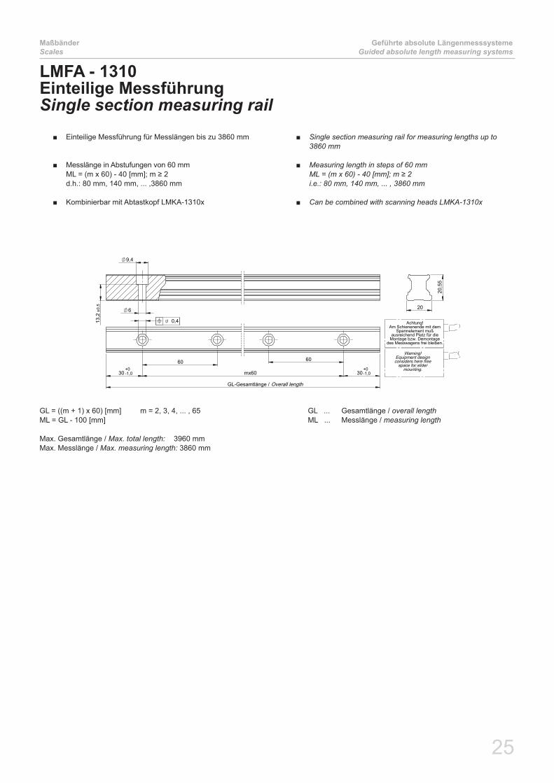
LMFA - 1310Einteilige MessführungSingle section measuring rail
GL = ((m + 1) x 60) [mm] m = 2, 3, 4, ... , 65 GL ... Gesamtlänge / overall length ML = GL - 100 [mm] ML ... Messlänge / measuring length
Max. Gesamtlänge / Max. total length: 3960 mmMax. Messlänge / Max. measuring length: 3860 mm
Einteilige Messführung für Messlängen bis zu 3860 mm ■
Messlänge in Abstufungen von 60 mm ■ML = (m x 60) - 40 [mm]; m ≥ 2 d.h.: 80 mm, 140 mm, ... ,3860 mm
Kombinierbar mit Abtastkopf LMKA-1310x ■
Single section measuring rail for measuring lengths up to ■3860 mm
Measuring length in steps of 60 mm ■ML=(mx60)-40[mm];m≥2 i.e.: 80 mm, 140 mm, ... , 3860 mm
Can be combined with scanning heads LMKA-1310x ■

26
Geführte absolute LängenmesssystemeGuided absolute length measuring systems
MaßbänderScales
30 mx60 30 30 64x60=3840 30
RL-Schinenreststück / nx3900
GL-Gesamtlänge /
+0-1,0
+0-1,0
0,4
9,4
6
13,2
±0,5 20
20,5
5
Achtung!Am Schienenende mit dem
Spannelement mußausreichend Platz für die
Montage bzw. Demontagedes Messwagens frei bleiben.
Warning!Equipment designconsiders here free
space for slidermounting.
Overall length
Rest length rail
LMFA - 1310/2310Mehrteilige MessführungMultiple section measuring rail
GL = (n x 3900) + RL [mm] n = 1, 2, 3, ... GL ... Gesamtlänge / overall length RL=((m+1)x60)[mm] m=1,2,3,...64 RL... Restlänge/ Remaining length ML = GL - 100 [mm] ML ... Messlänge / measuring length
Mehrteilige Messführung für Messlängen größer 3860 mm ■
Messlänge in Abstufungen von 60 mm ■ML = (n x 3900) + (m x 60) - 40 [mm]
Kombinierbar mit Abtastkopf LMK-1310x/2310x ■
Multiple section measuring rail for measuring lengths greater ■than 3860 mm
Measuring length in steps of 60 mm ■ML=(nx3900)+(mx60)-40[mm]
Can be combined with scanning heads LMK-1310x/2310x ■
BestellcodeOrdering code
Messlänge in mmMeasuring length in mm
LinearitätsfehlerLinearity error
1 ... ± 10 µm/m 2 ... ± 5 µm/m 3 ... ± 3 µm/m
GesamtlängeOverall length
1 ... ≤ 9200 mm 2 ... > 9200 mm
BeschichtungCoating
0 ... ohne / without 1 ... mit Cr / with Cr
LMFA- 310. -

27
AbtastkopfScanning head
Geführte absolute LängenmesssystemeGuided absolute length measuring systems
Technische DatenTechnical data
LMKA-1310x LMKA-2310x
Arbeitstemperatur:Operating temperature: 0°C … 80°C
Lagertemperatur:Storage temperature: -20°C … 85°C
Schutzart:Protection class: IP67
Vibration:Vibration: < 200 m/s² für (for) 55 – 2000 Hz
Schock:Shock: < 2000 m/s² für (for) 6 ms
Versorgung:Power supply: 3,5V bis (to) 5,5V
Stromaufnahme:Power consumption: max. 250 mA @ 5,0V (360mA @ 3,5V; 230mA @ 5,5V)
Inkrementelle Teilungsperiode:Incremental grating pitch: 1000 µm
Max. Massbandlänge:Max. scale length: ≤ 9200 mm > 9200 mm
Max. Verfahrgeschwindigkeit:Max. speed: 5 m/s für 1µm; 2,5 m/s für 0,25µm, limitiert durch die Mechanik / limited by the mechanics
Systemauflösung:System resolution:
Absolutes interface:Absolute interface:
1 µm / 0,25µm1 µm / 0,25µm
Analogausgang 1Vss: Analog output 1Vpp:
1000 µm oder 40 µm1000 µm or 40 µm
Absolutschnittstellen:Absolute interfaces:
SSI (200kHz ... 1MHz and Sine/Cosine)BiSS/C (max. Taktfrequenz / max. clock frequency: 2,5 MHz)
FANUC, DRIVE-CLiQMitsubishi & Yaskawa in Vorbereitung (in preparation)
Andere Schnittstellen auf AnfrageOther interfaces on request
Passende Maßverkörperung:Suitable measuring scale:
LMFA-1310
siehe Seite 25 / see page 25
LMFA-2310
siehe Seite 25 / see page 25
LMKA-1310x/2310xAbtastkopf für geführte absolute LängenmesssystemeScanning head for guided absolute length measuring systemsDie geführten Abtastköpfe LMKA-1310x/2310x mit integrierter Auswer-teelektronik sind mit den Messschienen LMF-1310/2310 (siehe Seite 25) kombinierbar.Der Abtastkopf Typ LMKA-1310x kann nur mit Messschienen LMFA-1310 bzw. der Abtastkopf Typ LMKA-2310x nur mit Messschienen LMFA-2310 verwendet werden.Die Systeme zeichnen sich durch ihre hohe Schutzart und Unempfind-lichkeit gegenüber Verschmutzung (Öl, Kühlschmiermittel, etc.) aus. Durch die Option den Abtastkopf mittels eines Federelementes zu mon-tieren sind auch höhere Montagetoleranzen, wie sie z.B. bei großen Messlängen auftreten, realisierbar.
The guided scanning heads LMKA-1310x/2310x with integrated eva-luation electronics can be combined with the measuring rails LMFA-1310/2310 (see page 25).Scanning head LMKA-1310x can be used only with rail type LMFA-1310 and scanning head LMKA-2310x can be used only with rail type LMFA-2310.The systems are insensitive against environmental pollution (i.e. oil, coolant, ...). Because of the option to mount the scanning head using the mounting spring high mounting tolerances, especially for longer measuring length, can be realized.
28
Geführte absolute LängenmesssystemeGuided absolute length measuring systems
AbtastkopfScanning head
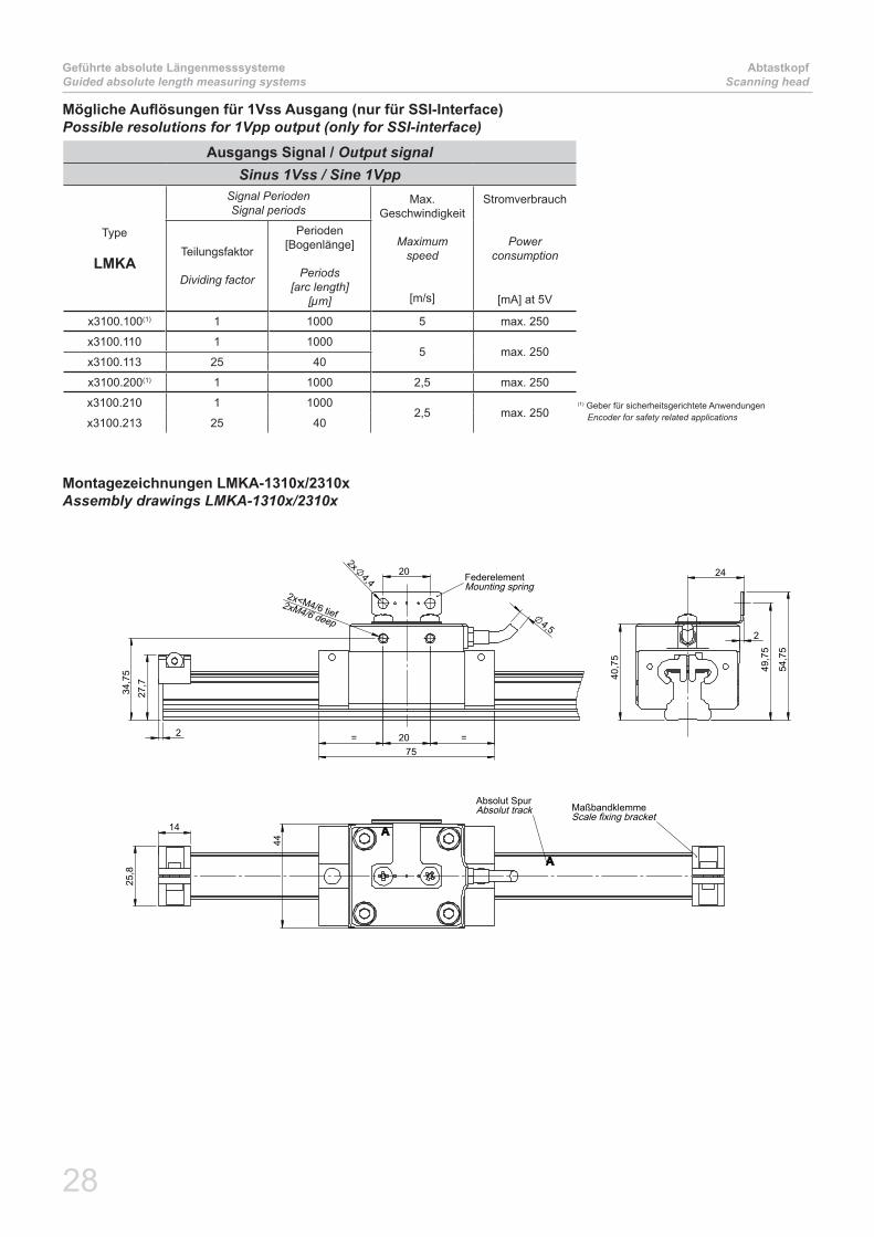
Mögliche Auflösungen für 1Vss Ausgang (nur für SSI-Interface)Possible resolutions for 1Vpp output (only for SSI-interface)
Ausgangs Signal / Output signalSinus 1Vss / Sine 1Vpp
Type
LMKA
Signal PeriodenSignal periods
Max.Geschwindigkeit
Maximumspeed
[m/s]
Stromverbrauch
Powerconsumption
[mA] at 5V
Teilungsfaktor
Dividing factor
Perioden[Bogenlänge]
Periods [arc length]
[µm]
x3100.100(1) 1 1000 5 max. 250
x3100.110 1 10005 max. 250
x3100.113 25 40
x3100.200(1) 1 1000 2,5 max. 250
x3100.210 1 10002,5 max. 250
x3100.213 25 40
24
2
54,
75
40,
75
49,
75
27,7
202x
4,4
75 20 = = 2
2x<M4/6 tief
34,
75
4,5
FederelementMounting spring
2xM4/6 deep
14
25,8
44
MaßbandklemmeScale fixing bracket
Absolut SpurAbsolut track
Montagezeichnungen LMKA-1310x/2310xAssembly drawings LMKA-1310x/2310x
(1) Geber für sicherheitsgerichtete Anwendungen Encoder for safety related applications

29
AbtastkopfScanning head
Offene absolute LängenmesssystemeOpen absolute length measuring systems
Kabellänge in MeterCable length in meter
Bevorzugte Kabellänge in 0,5m Schrittenpreferred cable length in steps of 0,5m
MassbandlängeScale length
1 ... ≤ 9200 mm 2 ... > 9200 mm
Absolute - InterfaceAuflösung in bit/Teilungsperiode (1)
Resolution in bit per grating pitch (1)
1 .......1µm2 .......0,25µm4 .......1µm (2)
5........0,25 µm (2)
(1) SSI Beschreibung auf Homepage www.amo-gmbh.com SSI Description on our website www.amo-gmbh.com(2) für neue Projekte, siehe SSI Beschreibung for new Projects, see SSI Description
SteckertypConnector type
0 ...... ohne / none 2 ...... 20 pol FANUC Stecker 20 pin FANUC connector5 ...... 15 pol. Sub-D Stecker 15 pin Sub-D connector 7 ...... 17 pol. M23 Kupplung (Stift) 17 pin M23 coupling (male)
LMKA- 3100 -. , -
Max. EingangsfrequenzMax. input frequency(nur für SSI / only for SSI)
0(1) ... 9 kHz (1µm) / 2,4 kHz (0,25µm) 1 ... 9 kHz (1µm) / 2,4 kHz (0,25µm)
(1) Geber für sicherheitsgerichtete Anwendungen Encoder for safety related applications Nur mit analogen Teilungsfaktor 1 möglich only with analog dividing factor 1 possible
Analoger Teilungsfaktor 1VssAnalog dividing factor 1Vpp(nur für SSI / only for SSI)
0 ... 1 (1000 µm) 3 ... 25 (40 µm)
Bestellcode: LMKA-1310x/2310x/1110x/2110x mit SSI InterfaceOrdering code: LMKA-1310x/2310x/1110x/2110x with SSI Interface
SSI geführt / guided
SSI
Bestellcode: LMKA-1310x/2310x/1110x/2110x Ordering code: LMKA-1310x/2310x/1110x/2110x
Kabellänge in MeterCable length in meter
Bevorzugte Kabellänge in 0,5m Schrittenpreferred cable length in steps of 0,5m
MassbandlängeScale length
1 ... ≤ 9200 mm 2 ... > 9200 mm
Absolute - InterfaceAuflösung in µmResolution in µm
1 .......1µm2 .......0,25µm
SteckertypConnector type
0 ...... ohne / none 2 ...... 20 pol FANUC Stecker 20 pin FANUC connector5 ...... 15 pol. Sub-D Stecker 15 pin Sub-D connector 7 ...... 17 pol. M23 Kupplung (Stift) 17 pin M23 coupling (male)C ......10 pol. Mitsubishi Stecker (nur für Mitsubishi Interface) 10 pin Mitsubishi connector (only for Mitsubishi Interface)
InterfaceType 1 ... BISS/C3 ... FANUC4 ... Mitsubishi5 (1).. Yaskawa
(1) In Vorbereitung in preparation
LMKA- 310 -. , -NN
LMKA- 110 -. , -NN
LMKA- 1100 -. -,
geführt / guided

30
Geführte absolute LängenmesssystemeGuided absolute length measuring systems
AbtastkopfScanning head
Bestellcode: LMKA-1310x/2310x/1110x/2110x mit DRIVE CLiQ - InterfaceOrdering code: LMKA-1310x/2310x/1110x/2110x with DRIVE CLiQ - Interface
MassbandlängeScale length
1 ... ≤ 9200 mm 2 ... > 9200 mm
Absolute - InterfaceAuflösung in µmResolution in µm
1 .......1µm2 .......0,25µm
Max. EingangsfrequenzMax. input frequency 1 ... 9 kHz (1µm) / 2,4 kHz (0,25µm)
SteckertypConnector type 8 ...... 8 pol M12 Stecker (nur für DriveCLiQ) 8 pin M12 connector (just for DriveCLiQ)
LMKA- 3102 -. -1 N 0,5 08
Kabellänge 0,5 MeterCable length 0,5 meter
LMKA- 1102 -. -1 N 0,5 08

31
Allgemeine InformationenGeneral information
Maximale DrehzahlenMaximum speed
Maximale DrehzahlenMaximum speeda) Max. Drehzahl / Max. speed
Die maximale mögliche Drehzahl nmax für ein Messsystem errechnet sich aus der max. Eingangsfrequenz f des Abtastkopfes und der Anzahl der Teilstriche pro Umdrehung N des Messflansches wie folgt:
The maximum speed nmax of a measuring system can be calculated considering the max. input frequency f of the scanning head and the num-ber of pitches per revolution Nofthemeasuringflangeasfollows:
nmax [U/min] = f[Hz] x 60 / N nmax [rpm] = f[Hz] x 60 / N
b) Ausgangsfrequenz / Output frequency
Die maximale Ausgangsfrequenz fa des Abtastkopfes ist abhängig von der max. Drehzahl n der Applikation, der Anzahl der Teilstriche pro Umdrehung N des Messflansches und dem Teilungsfaktor D des Abtastkopfes. Es ist darauf zu achten, das die max. Ausgangsfrequenz die Grenzfrequenz der Nachfolgeelektronik nicht übersteigt.
The max. output signal frequency fa of the scanning head depends on the max. speed n used in the application, the number of grating pitches per revolution N and the dividing factor D of a scanning head.It’s important to not exceed the max. input frequency of the subsequent electronics.
fa [Hz] = (n[U/min] / 60) x N x D für Abtastkopf mit 1Vss-Ausgang fa [Hz] = (n[rpm] / 60) x N x D for scanning head with 1Vpp output
In den nachfolgenden Tabellen sind max. Drehzahlen für Standardmessflansche bzw. Messringe angeführt.Maximumrotaryspeedsforstandardmeasuringflangesrespectivelymeasuringringsareshownbelow.
Typ Type
Max. Eingangs-frequenz
Max. input frequency
f[khz]
Drehzahl n [U/min] Rotary speed n [rev/min]
Standardmessflansch WMFA-210x oder Messring WMRA-210xStandard measuring flange WMFA-210x or measuring ring WMRA-210x
0256 0360 0512 0720 0900 1024 1440 1800 2048
WMKA-2x100.100 9 2100 1500 1050 750 600 520 370 300 260
WMKA-2x10x.1xx 9 2100 1500 1050 750 600 520 370 300 260
WMKA-2x100.130 60 14000 10000 7000 5000 4000 3500 2500 2000 1750
WMKA-2x10x.2xx 2,4 560 400 280 200 160 140 100 80 70

32
KabelCable
Allgemeine InformationenGeneral information
Bestellcode: VerlängerungskabelOrdering code: extension cable
VK - 4 - - -
10A .. ohne Stecker without connector15A .. 15 pol. SUB-D 15 pin SUB-D18A .. 17 pol. M23-Stecker CCW 17 pin M23 connector CCW19A .. Sonderstecker oder Sonderbelegung Special connector or special pin assignments
00A .. ohne Stecker without connector02A 20 pol FANUC Stecker 20 pin FANUC connector05A .. 15 pol. SUB-D 15 pin SUB-D07A .. 17 pol. M23-Kupplung CW 17 pin M23 coupling CW09A .. Sonderstecker oder Sonderbelegung Special connector or special pin assignments
Kabellängein Meter
Cable lengthin meter
Kabellänge /Cable length StiftPin
VerlängerungskabelExtension cable
BuchseSocket
MesssystemMeasuring system
KabelCable
Kabel für MesssystemCable for measuring system
VerlängerungskabelExtension cable
Mantel:Jacket:
PUR, hochflexibel, schleppkettentauglichPUR,highflexible,suitableforenergychains
Durchmesser:Diameter: 4,5mm ~ 8mm
Adern:Wires:
1(4x0,09)+1(4x0,14) mm2 (rein serielle Schnittstelle)6x2x0,09 mm² (serielle Schnittstelle + 1Vss) 4 (2 x 0,14) + 2 ( 2 x 0,5) mm2
Biegeradius:Bending radius:Einmalbiegung:Single bending: 10mm 40mm
Dauerbiegung:Continuous bending: 50mm 80mm
Max. Länge:Max. length: 9m 50m
Technische DatenTechnical data
33
Allgemeine InformationenGeneral information
SteckerbelegungenPlug and pin assignments
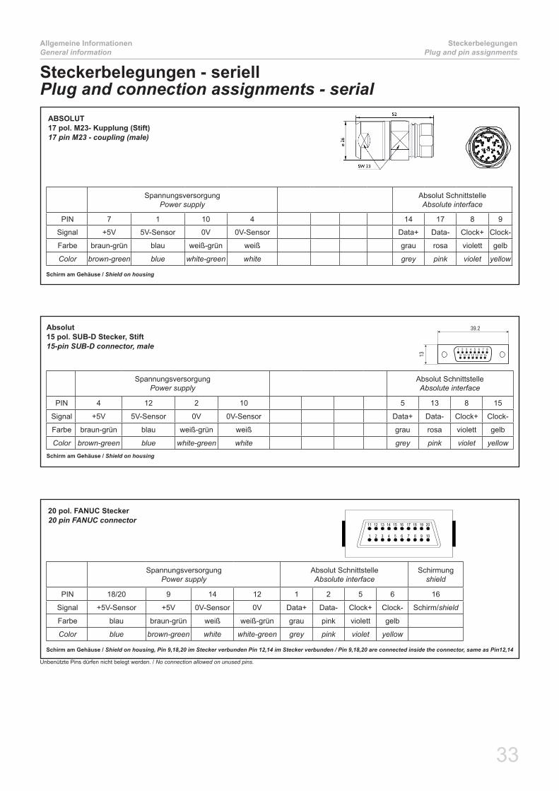
Steckerbelegungen - seriellPlug and connection assignments - serial
ABSOLUT17 pol. M23- Kupplung (Stift)17 pin M23 - coupling (male)
58
26
M23x1
SpannungsversorgungPower supply
Absolut SchnittstelleAbsolute interface
PIN 7 1 10 4 14 17 8 9
Signal +5V 5V-Sensor 0V 0V-Sensor Data+ Data- Clock+ Clock-
Farbe braun-grün blau weiß-grün weiß grau rosa violett gelb
Color brown-green blue white-green white grey pink violet yellow
Schirm am Gehäuse / Shield on housing
Absolut15 pol. SUB-D Stecker, Stift 15-pin SUB-D connector, male
SpannungsversorgungPower supply
Absolut SchnittstelleAbsolute interface
PIN 4 12 2 10 5 13 8 15
Signal +5V 5V-Sensor 0V 0V-Sensor Data+ Data- Clock+ Clock-
Farbe braun-grün blau weiß-grün weiß grau rosa violett gelb
Color brown-green blue white-green white grey pink violet yellowSchirm am Gehäuse / Shield on housing
Unbenützte Pins dürfen nicht belegt werden. / No connection allowed on unused pins.
20 pol. FANUC Stecker20 pin FANUC connector
SpannungsversorgungPower supply
Absolut SchnittstelleAbsolute interface
Schirmung shield
PIN 18/20 9 14 12 1 2 5 6 16
Signal +5V-Sensor +5V 0V-Sensor 0V Data+ Data- Clock+ Clock- Schirm/shield
Farbe blau braun-grün weiß weiß-grün grau pink violett gelb
Color blue brown-green white white-green grey pink violet yellow
Schirm am Gehäuse / Shield on housing, Pin 9,18,20 im Stecker verbunden Pin 12,14 im Stecker verbunden / Pin 9,18,20 are connected inside the connector, same as Pin12,14
1 2 3 74 5 86 9 10
11 12 2013 14 15 16 17 18 19
34
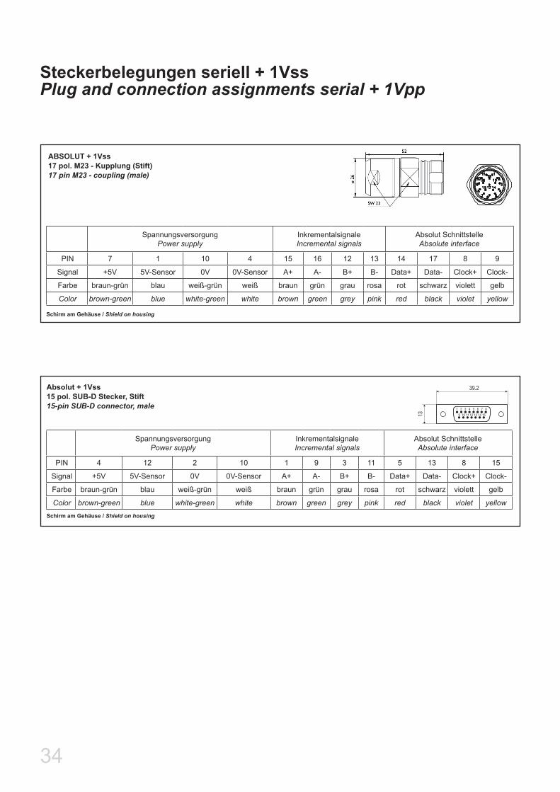
Steckerbelegungen seriell + 1VssPlug and connection assignments serial + 1Vpp
Absolut + 1Vss15 pol. SUB-D Stecker, Stift 15-pin SUB-D connector, male
SpannungsversorgungPower supply
InkrementalsignaleIncremental signals
Absolut SchnittstelleAbsolute interface
PIN 4 12 2 10 1 9 3 11 5 13 8 15
Signal +5V 5V-Sensor 0V 0V-Sensor A+ A- B+ B- Data+ Data- Clock+ Clock-
Farbe braun-grün blau weiß-grün weiß braun grün grau rosa rot schwarz violett gelb
Color brown-green blue white-green white brown green grey pink red black violet yellowSchirm am Gehäuse / Shield on housing
ABSOLUT + 1Vss17 pol. M23 - Kupplung (Stift)17 pin M23 - coupling (male)
58
26
M23x1
SpannungsversorgungPower supply
InkrementalsignaleIncremental signals
Absolut SchnittstelleAbsolute interface
PIN 7 1 10 4 15 16 12 13 14 17 8 9
Signal +5V 5V-Sensor 0V 0V-Sensor A+ A- B+ B- Data+ Data- Clock+ Clock-
Farbe braun-grün blau weiß-grün weiß braun grün grau rosa rot schwarz violett gelb
Color brown-green blue white-green white brown green grey pink red black violet yellow
Schirm am Gehäuse / Shield on housing
Weitere ProduktbrochürenAdditional product brochures
SpindelgeberSpindle encoder
Kompakte Bauform ■Compact desig
Höchste Drehzahlen bis zu ■26.000 U/minHigh speeds up to 26,000 rpm
Hohe EMV-Festigkeit ■High EMC immunity
Keine magnetischen ■Komponenten oder Felder, Hysterese oder Entmagneti-sierungsgefahrNo magnetic components No magnetic field hystere-sis or demagnetisation risk
Schutzklasse IP67 ■wasserdichte ImpulsgeberProtection class IP67 Fluid submersible encoders
Spindelgeber nach dem AMOSIN® – MessprinzipSpindle encoder based on the AMOSIN® – Inductive Measuring Principle
AMO GmbH
ProduktübersichtProduct overview
AMO GmbH
Inductive encoders comparable ■to optical encoders in both, accuracy and resolution
No magnetic components, no ■magnetic fields, hysteresis or demagnetisation risk
Protection class IP67 ■Fluid submersible encoders
Product overview:
IncrementalLENGTH- AND ANGLE MEASURINGSYSTEMS based on the AMOSIN® –Inductive Measuring Principle
LängenmesssystemeLength measuring systems
AMO GmbH
Inkrementelle LÄNGENMESSSYSTEME nach dem induktiven AMOSIN® – Messprinzip
Incremental LENGTH MEASURING SYSTEMS based on the AMOSIN® – Inductive Measuring Principle
WinkelmesssystemeAngle measuring systems
AMO GmbH
Inkrementelle WINKELMESSSYSTEME nach dem induktiven AMOSIN® – Messprinzip
Incremental ANGLE MEASURING SYSTEMS based on the AMOSIN® – Inductive Measuring Principle

A-4963 St. Peter am Hart, Nöfing 4 - Austria
Phone: +43 7722 658 56-0Fax: +43 7722 658 56-11
e-mail: [email protected]
www.amo-gmbh.com
Technische Änderungen vorbehalten.Technical data are subject to change without notice.
Branches:
Germany:
AMO GmbHZweigniederlassung Deutschland
Bussardstrasse 10D 78655 Dunningen
Phone: +49 7403 913 283Fax.: +49 7403 913 267
e-mail: [email protected]
USA:
AMO Corporation9580 Oak Ave Parkway Suite 7-162
Folsom, CA 95630
Phone: +1 916 791 2001Fax: +1 916 720 0430
E-mail: [email protected]: www.amosin.com
Italy:
AMO Italia s.r.l.20037 Paderno Dugnano MI - Italia
Via Gorizia 35
Phone: +39 029 108 23 41
E-mail: [email protected]: www.amoitalia.it
Authorized distributors and sales partners in other countries:
Please look at www.amo-gmbh.com
Headquarter:
AMO GmbH