Applications of a Generic Component Framework to a UML ... · UML varies widely. In development...
122
Applications of a Generic Component Framework to a UML Case Study in Production Automation Diplomarbeit im Fach Informatik, TU Berlin Vorgelegt von Martti Piirainen 17. Februar 2003 Betreuer und 1. Gutachter: Prof. Hartmut Ehrig, Technische Universität Berlin 2. Gutachter: Prof. Fernando Orejas, Universitat Politècnica de Catalunya
Transcript of Applications of a Generic Component Framework to a UML ... · UML varies widely. In development...
Applications of a GenericComponent Framework to a UML Case Study
in Production Automation
Diplomarbeit im Fach Informatik, TU BerlinVorgelegt von Martti Piirainen
17. Februar 2003
Betreuer und 1. Gutachter:Prof. Hartmut Ehrig, Technische Universität Berlin
2. Gutachter:Prof. Fernando Orejas, Universitat Politècnica de Catalunya

ii

Die selbständige und eigenhändige Anfertigung dieser Arbeit versichere ichan Eides statt.
Berlin, den 17. Februar 2003
Martti Piirainen
iii

iv

Zusammenfassung
In dieser Arbeit werden ein neuer Komponentenbegriff für UML-Klassendiagram-me und die Komposition solcher Komponenten definiert. Dafür werden einfacheBegriffe der Inklusion und Verfeinerung von statischen Modellen eingeführt.
Dieses Komponentenkonzept ist mit Hilfe der UML-Erweiterungsmechanismenformuliert. Ein Ergebnis ist ein UML-Profil für komponentenbasierte Modellie-rung. Als weiteres Ergebnis wird bewiesen, dass dieses Komponentenkonzept eineInstanziierung des Generischen Komponentenrahmenwerks von Ehrig et al. ist.
Das Komponentenkonzept wird auf eine UML-Fallstudie aus der Domäne Pro-duktionsautomatisierung angewendet, indem das bereits entwickelte Modell in derin dieser Arbeit definierten Terminologie und Notation reformuliert wird. Außer-dem wird skizziert, wie ein Komponentenkonzept, das alle UML-Techniken, ins-besondere Verhaltensspezifikationen, umfasst, erreicht werden könnte. Die Ergeb-nisse dieser Arbeit werden mit anderen existierenden Ansätzen zur Komponenten-modellierung mit Hilfe der UML verglichen.
Abstract
In this thesis, a new notion of components for UML class diagrams and composi-tion of such components are defined. Therefore, simple notions of inclusion andrefinement of static models are introduced.
This component concept is formulated using the UML extension mechanisms.One result is a UML profile for component-based modelling. As a second result, itis proven that this component concept is an instantiation of the Generic ComponentFramework by Ehrig et al.
The component concept is applied to an existing UML case study in the domainof production automation, by reformulating the model developed previously in theterminology and notation defined in this thesis. Additionally, it is sketched howa component concept covering all of the UML techniques, especially behaviouralspecifications, could be approached. The results of the thesis are compared withother existing approaches to component modelling using the UML.
v

Contents
1 Introduction 11.1 Precise Component-Based Modelling. . . . . . . . . . . . . . . 11.2 A Generic Component Framework. . . . . . . . . . . . . . . . . 21.3 The Unified Modelling Language (UML). . . . . . . . . . . . . 5
1.3.1 The UML Meta-Model. . . . . . . . . . . . . . . . . . . 61.4 Refinement and Similar Concepts. . . . . . . . . . . . . . . . . 91.5 Goals and Methods of the Thesis. . . . . . . . . . . . . . . . . . 11
2 A Component Framework for UML Class Diagrams 132.1 Prerequisites. . . . . . . . . . . . . . . . . . . . . . . . . . . . . 13
2.1.1 Motivation for Packages as Component Parts. . . . . . . 142.2 Inclusion of Packages. . . . . . . . . . . . . . . . . . . . . . . . 15
2.2.1 The UML Import Dependency. . . . . . . . . . . . . . . 162.2.2 A New Import Stereotype. . . . . . . . . . . . . . . . . 21
2.3 Refinement of Classes and Packages. . . . . . . . . . . . . . . . 232.3.1 Refinement of Classes. . . . . . . . . . . . . . . . . . . 242.3.2 Excursus: Formalisation in Set Theory. . . . . . . . . . . 272.3.3 Class Refinement is a Partial Order. . . . . . . . . . . . 282.3.4 OCL and Refinement. . . . . . . . . . . . . . . . . . . . 302.3.5 Refinement of Packages. . . . . . . . . . . . . . . . . . 33
2.4 Components. . . . . . . . . . . . . . . . . . . . . . . . . . . . . 342.4.1 Notation variants. . . . . . . . . . . . . . . . . . . . . . 35
2.5 Component Interface Specifications. . . . . . . . . . . . . . . . 382.6 A UML Profile for Component Modelling. . . . . . . . . . . . . 402.7 Discussion of Design Decisions and Alternatives. . . . . . . . . 40
3 Instantiation of the Generic Component Framework 483.1 Specifications, Transformations, and Inclusions. . . . . . . . . . 483.2 Extension Property. . . . . . . . . . . . . . . . . . . . . . . . . 503.3 Vertical and Horizontal Composition of Extension Diagrams. . . 533.4 Hierarchical Composition of Components. . . . . . . . . . . . . 533.5 Multi-Interface Components and Partial Composition. . . . . . . 54
vi
4 Towards a Component Framework for the UML 584.1 Components Modelled with All UML Diagram Types. . . . . . . 584.2 Behavioural Specification and Refinement. . . . . . . . . . . . . 60
4.2.1 Protocol Statecharts. . . . . . . . . . . . . . . . . . . . 624.2.2 Protocol Statechart Refinement. . . . . . . . . . . . . . . 67
4.3 Components in the Context of Software Development Processes. 714.3.1 Refinement of Components. . . . . . . . . . . . . . . . 724.3.2 Composing a System. . . . . . . . . . . . . . . . . . . . 75
4.4 Component Lifecycle Issues. . . . . . . . . . . . . . . . . . . . 75
5 UML Case Study in Production Automation 775.1 The Production Environment. . . . . . . . . . . . . . . . . . . . 775.2 The Software Components of the Case Study. . . . . . . . . . . 785.3 Composing the Software System. . . . . . . . . . . . . . . . . . 91
5.3.1 Behavioural Composition. . . . . . . . . . . . . . . . . 915.3.2 Component Instantiation. . . . . . . . . . . . . . . . . . 97
6 Related Work and Conclusion 986.1 UML Component Concept Developed in the IOSIP Case Study. . 986.2 UML Components . . . . . . . . . . . . . . . . . . . . . . . . . 996.3 Component Interface Diagrams. . . . . . . . . . . . . . . . . . . 1006.4 Contract-Aware Components. . . . . . . . . . . . . . . . . . . . 1016.5 Architectural Connectors and Coordination Contracts. . . . . . . 1026.6 CORBA Component Model. . . . . . . . . . . . . . . . . . . . . 1036.7 Conclusion . . . . . . . . . . . . . . . . . . . . . . . . . . . . . 106
A Self-Defined OCL Functions 108
Bibliography 110
vii
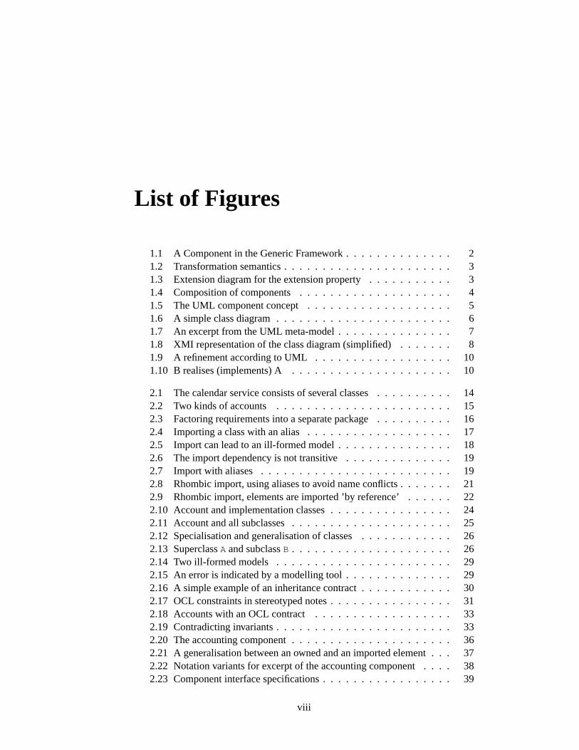
List of Figures
1.1 A Component in the Generic Framework. . . . . . . . . . . . . . 21.2 Transformation semantics. . . . . . . . . . . . . . . . . . . . . . 31.3 Extension diagram for the extension property. . . . . . . . . . . 31.4 Composition of components. . . . . . . . . . . . . . . . . . . . 41.5 The UML component concept. . . . . . . . . . . . . . . . . . . 51.6 A simple class diagram. . . . . . . . . . . . . . . . . . . . . . . 61.7 An excerpt from the UML meta-model. . . . . . . . . . . . . . . 71.8 XMI representation of the class diagram (simplified). . . . . . . 81.9 A refinement according to UML. . . . . . . . . . . . . . . . . . 101.10 B realises (implements) A. . . . . . . . . . . . . . . . . . . . . 10
2.1 The calendar service consists of several classes. . . . . . . . . . 142.2 Two kinds of accounts. . . . . . . . . . . . . . . . . . . . . . . 152.3 Factoring requirements into a separate package. . . . . . . . . . 162.4 Importing a class with an alias. . . . . . . . . . . . . . . . . . . 172.5 Import can lead to an ill-formed model. . . . . . . . . . . . . . . 182.6 The import dependency is not transitive. . . . . . . . . . . . . . 192.7 Import with aliases. . . . . . . . . . . . . . . . . . . . . . . . . 192.8 Rhombic import, using aliases to avoid name conflicts. . . . . . . 212.9 Rhombic import, elements are imported ’by reference’. . . . . . 222.10 Account and implementation classes. . . . . . . . . . . . . . . . 242.11 Account and all subclasses. . . . . . . . . . . . . . . . . . . . . 252.12 Specialisation and generalisation of classes. . . . . . . . . . . . 262.13 SuperclassA and subclassB . . . . . . . . . . . . . . . . . . . . . 262.14 Two ill-formed models . . . . . . . . . . . . . . . . . . . . . . . 292.15 An error is indicated by a modelling tool. . . . . . . . . . . . . . 292.16 A simple example of an inheritance contract. . . . . . . . . . . . 302.17 OCL constraints in stereotyped notes. . . . . . . . . . . . . . . . 312.18 Accounts with an OCL contract. . . . . . . . . . . . . . . . . . 332.19 Contradicting invariants. . . . . . . . . . . . . . . . . . . . . . . 332.20 The accounting component. . . . . . . . . . . . . . . . . . . . . 362.21 A generalisation between an owned and an imported element. . . 372.22 Notation variants for excerpt of the accounting component. . . . 382.23 Component interface specifications. . . . . . . . . . . . . . . . . 39
viii
2.24 Component modelling profile. . . . . . . . . . . . . . . . . . . . 412.25 Application of a profile. . . . . . . . . . . . . . . . . . . . . . . 412.26 Components using delegation. . . . . . . . . . . . . . . . . . . . 442.27 Components using inheritance. . . . . . . . . . . . . . . . . . . 452.28 Components using interfaces only. . . . . . . . . . . . . . . . . 462.29 An adapter component connecting legacy components. . . . . . . 47
3.1 Example of extension property. . . . . . . . . . . . . . . . . . . 513.2 Extension diagram for packages. . . . . . . . . . . . . . . . . . 513.3 Horizontal composition of extension diagrams. . . . . . . . . . . 533.4 Composition of components. . . . . . . . . . . . . . . . . . . . 553.5 Structured composition of components. . . . . . . . . . . . . . . 563.6 Extension diagram for multiple interfaces. . . . . . . . . . . . . 57
4.1 UML diagram types. . . . . . . . . . . . . . . . . . . . . . . . . 584.2 A use case diagram for the accounting component. . . . . . . . . 604.3 Equivalent statechart and activity diagrams forTransientAccount 614.4 A Message Sequence Diagram representing a scenario ”emptying
the account”. . . . . . . . . . . . . . . . . . . . . . . . . . . . . 614.5 Superclass and subclass are specified with statecharts. . . . . . . 624.6 An excerpt of the statechart meta-model. . . . . . . . . . . . . . 634.7 Three situations of protocol statechart refinement. . . . . . . . . 664.8 Mappings allowed in a statechart homomorphism. . . . . . . . . 684.9 Two transitions . . . . . . . . . . . . . . . . . . . . . . . . . . . 694.10 Refining an excerpt of a statechart, preserving observable traces. 704.11 Refinement of a component. . . . . . . . . . . . . . . . . . . . . 724.12 Example for refinement of a component. . . . . . . . . . . . . . 734.13 Body refinement. . . . . . . . . . . . . . . . . . . . . . . . . . . 744.14 Component interface realisation. . . . . . . . . . . . . . . . . . 744.15 Connecting a component with an existing library. . . . . . . . . 754.16 Client using a component. . . . . . . . . . . . . . . . . . . . . . 75
5.1 Production system overview. . . . . . . . . . . . . . . . . . . . 785.2 Data types used commonly. . . . . . . . . . . . . . . . . . . . . 795.3 Negotiator component. . . . . . . . . . . . . . . . . . . . . . 805.4 Negotiator statechart. . . . . . . . . . . . . . . . . . . . . . . 815.5 NegotiatorBod statechart . . . . . . . . . . . . . . . . . . . . 815.6 Substateprocess offer of NegotiatorBod statechart . . . . 825.7 Substateprocess machine state of NegotiatorBod statechart835.8 I/O component . . . . . . . . . . . . . . . . . . . . . . . . . . . 845.9 Sender statechart. . . . . . . . . . . . . . . . . . . . . . . . . . 855.10 Receiver statechart . . . . . . . . . . . . . . . . . . . . . . . . 855.11 Mediator component . . . . . . . . . . . . . . . . . . . . . . . 875.12 Statechart for the operationrequestAction . . . . . . . . . . . 88
ix
5.13 Interpreter component . . . . . . . . . . . . . . . . . . . . . 895.14 InterpreterBod statechart. . . . . . . . . . . . . . . . . . . . 905.15 Substates ofInterpreterBod statechart. . . . . . . . . . . . . 905.16 Communication component. . . . . . . . . . . . . . . . . . . . . 925.17 Communication component body. . . . . . . . . . . . . . . . . . 935.18 Production component. . . . . . . . . . . . . . . . . . . . . . . 945.19 System component. . . . . . . . . . . . . . . . . . . . . . . . . 955.20 System component – Overview. . . . . . . . . . . . . . . . . . . 955.21 Interpreter statechart. . . . . . . . . . . . . . . . . . . . . . 965.22 Composition of classes that are specified by statecharts. . . . . . 965.23 An excerpt of the composed system. . . . . . . . . . . . . . . . 97
6.1 Accounting component in the IOSIP notation. . . . . . . . . . . 996.2 Accounting, using UML components. . . . . . . . . . . . . . . . 996.3 Example of a Component according to Cheesman/Daniels. . . . 1006.4 Example of a Component Interface Diagram. . . . . . . . . . . . 1016.5 Example of contract-aware components. . . . . . . . . . . . . . 1026.6 Example of a coordination contract. . . . . . . . . . . . . . . . . 1026.7 An excerpt of the IOSIP model. . . . . . . . . . . . . . . . . . . 1046.8 CORBA 3 IDL for the IOSIP model. . . . . . . . . . . . . . . . 105
x
Chapter 1
Introduction
1.1 Precise Component-Based Modelling
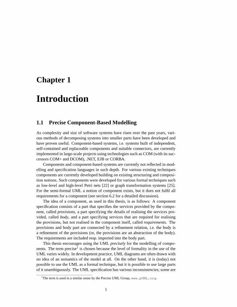
As complexity and size of software systems have risen over the past years, vari-ous methods of decomposing systems into smaller parts have been developed andhave proven useful. Component-based systems, i.e. systems built of independent,self-contained and replaceable components and suitable connectors, are currentlyimplemented in large-scale projects using technologies such as COM (with its suc-cessors COM+ and DCOM), .NET, EJB or CORBA.
Components and component-based systems are currently not reflected in mod-elling and specification languages in such depth. For various existing techniquescomponents are currently developed building on existing structuring and composi-tion notions. Such components were developed for various formal techniques suchas low-level and high-level Petri nets [22] or graph transformation systems [25].For the semi-formal UML a notion of component exists, but it does not fulfil allrequirements for a component (see section6.2for a detailed discussion).
The idea of a component, as used in this thesis, is as follows: A componentspecification consists of a part that specifies the services provided by the compo-nent, calledprovisions, a part specifying the details of realising the services pro-vided, calledbody, and a part specifying services that are required for realisingthe provisions, but not realised in the component itself, calledrequirements. Theprovisions and body part are connected by a refinement relation, i.e. the body isa refinement of the provisions (or, the provisions are an abstraction of the body).The requirements are included resp. imported into the body part.
This thesis encourages using the UMLpreciselyfor the modelling of compo-nents. The term precise1 is chosen because the level of formality in the use of theUML varies widely. In development practice, UML diagrams are often drawn withno idea of an semantics of the model at all. On the other hand, it is (today) notpossible to use the UML as a formal technique, but it is possible to use large partsof it unambiguously. The UML specification has various inconsistencies; some are
1The term is used in a similar sense by the Precise UML Group,www.pUML.org .
1
analysed in this thesis, others are shown elsewhere; hopefully most of them aregone in the next major version of the UML. Nevertheless, this thesis is not meantto be a critique of the UML, but shall constructively discuss some problems andhow to deal with them precisely.
1.2 A Generic Component Framework
A framework for component specifications that abstracts from the used specifica-tion technique is introduced in [9] and is shortly repeated here. This framework isgeneric in the sense that important results on compositionality were formulated andproven on an abstract level. In order to profit from these results in practice with aconcrete modelling or specification language, it is required to formulate a suitableinstantiationof the generic concept, i.e. to show that the properties required of theconcrete language are fulfilled.
Components
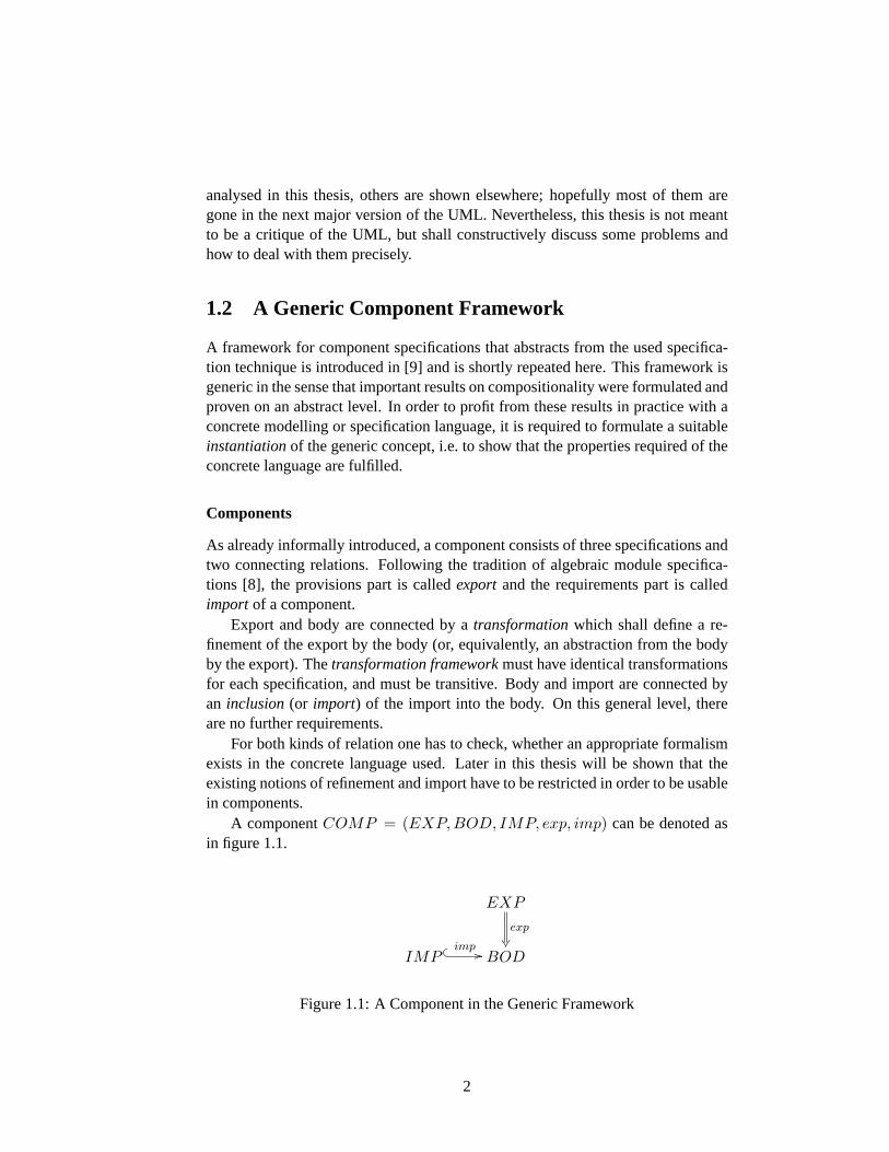
As already informally introduced, a component consists of three specifications andtwo connecting relations. Following the tradition of algebraic module specifica-tions [8], the provisions part is calledexportand the requirements part is calledimport of a component.
Export and body are connected by atransformationwhich shall define a re-finement of the export by the body (or, equivalently, an abstraction from the bodyby the export). Thetransformation frameworkmust have identical transformationsfor each specification, and must be transitive. Body and import are connected byan inclusion(or import) of the import into the body. On this general level, thereare no further requirements.
For both kinds of relation one has to check, whether an appropriate formalismexists in the concrete language used. Later in this thesis will be shown that theexisting notions of refinement and import have to be restricted in order to be usablein components.
A componentCOMP = (EXP, BOD, IMP, exp, imp) can be denoted asin figure1.1.
EXP
exp
®¶IMP
� � imp // BOD
Figure 1.1:A Component in the Generic Framework
2
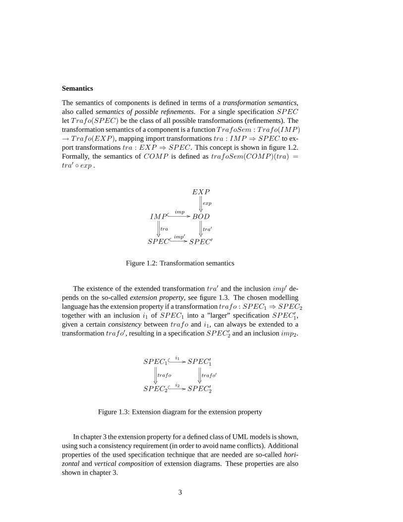
Semantics
The semantics of components is defined in terms of atransformation semantics,also calledsemantics of possible refinements. For a single specificationSPEClet Trafo(SPEC) be the class of all possible transformations (refinements). Thetransformation semantics of a component is a functionTrafoSem : Trafo(IMP )→ Trafo(EXP ), mapping import transformationstra : IMP ⇒ SPEC to ex-port transformationstra : EXP ⇒ SPEC. This concept is shown in figure1.2.Formally, the semantics ofCOMP is defined astrafoSem(COMP )(tra) =tra′ ◦ exp .
EXP
exp
®¶IMP
� � imp //
tra®
BOD
tra′®
SPEC� � imp′ // SPEC ′
Figure 1.2:Transformation semantics
The existence of the extended transformationtra′ and the inclusionimp′ de-pends on the so-calledextension property, see figure1.3. The chosen modellinglanguage has the extension property if a transformationtrafo : SPEC1 ⇒ SPEC2
together with an inclusioni1 of SPEC1 into a ”larger” specificationSPEC ′1,
given a certainconsistencybetweentrafo and i1, can always be extended to atransformationtrafo′, resulting in a specificationSPEC ′
2 and an inclusionimp2.
SPEC1
trafo
®
� � i1 // SPEC ′1
trafo′®
SPEC2� � i2 // SPEC ′
2
Figure 1.3:Extension diagram for the extension property
In chapter3 the extension property for a defined class of UML models is shown,using such a consistency requirement (in order to avoid name conflicts). Additionalproperties of the used specification technique that are needed are so-calledhori-zontalandvertical compositionof extension diagrams. These properties are alsoshown in chapter3.
3
In the context of the UML, which is not a formal language, it is usually im-possible to give a precise operational semantics. Therefore,such a transformationsemantics can be a valuable tool, because it is built rather on syntax of models thanon its semantics. The intuition that the semantics of a component depends on howthe requirements are fulfilled, is very well reflected.
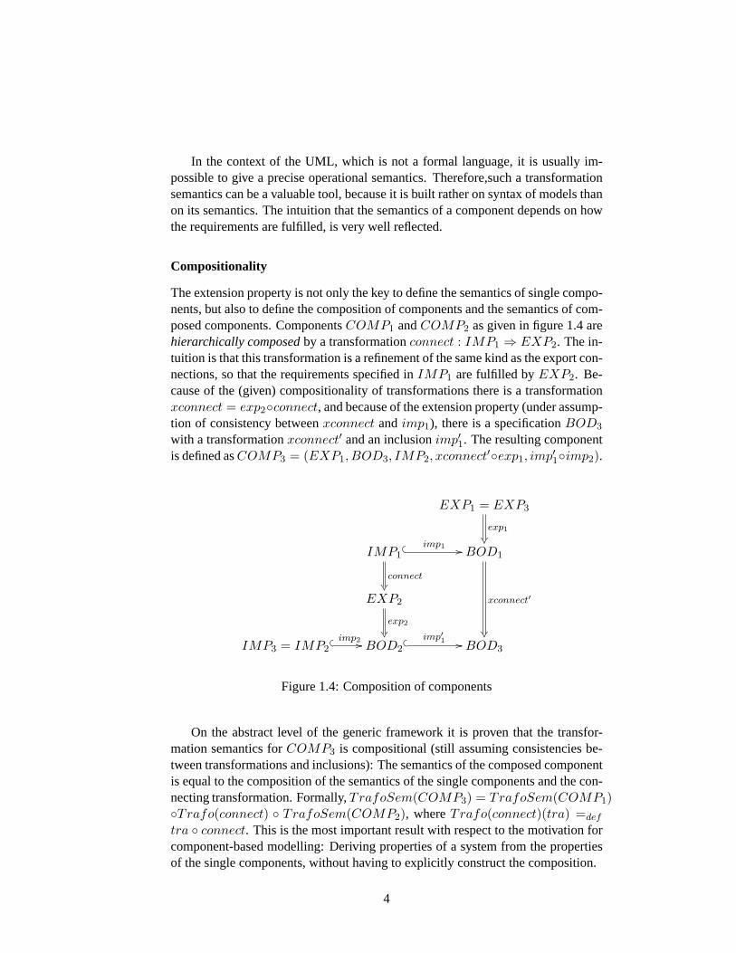
Compositionality
The extension property is not only the key to define the semantics of single compo-nents, but also to define the composition of components and the semantics of com-posed components. ComponentsCOMP1 andCOMP2 as given in figure1.4arehierarchically composedby a transformationconnect : IMP1 ⇒ EXP2. The in-tuition is that this transformation is a refinement of the same kind as the export con-nections, so that the requirements specified inIMP1 are fulfilled byEXP2. Be-cause of the (given) compositionality of transformations there is a transformationxconnect = exp2◦connect, and because of the extension property (under assump-tion of consistency betweenxconnect andimp1), there is a specificationBOD3
with a transformationxconnect′ and an inclusionimp′1. The resulting componentis defined asCOMP3 = (EXP1, BOD3, IMP2, xconnect′◦exp1, imp′1◦imp2).
EXP1 = EXP3
exp1
®¶IMP1
connect®
� � imp1 // BOD1
xconnect′
®
EXP2
exp2
®¶IMP3 = IMP2
� � imp2 // BOD2� � imp′1 // BOD3
Figure 1.4:Composition of components
On the abstract level of the generic framework it is proven that the transfor-mation semantics forCOMP3 is compositional (still assuming consistencies be-tween transformations and inclusions): The semantics of the composed componentis equal to the composition of the semantics of the single components and the con-necting transformation. Formally,TrafoSem(COMP3) = TrafoSem(COMP1)◦Trafo(connect) ◦ TrafoSem(COMP2), whereTrafo(connect)(tra) =def
tra ◦ connect. This is the most important result with respect to the motivation forcomponent-based modelling: Deriving properties of a system from the propertiesof the single components, without having to explicitly construct the composition.
4
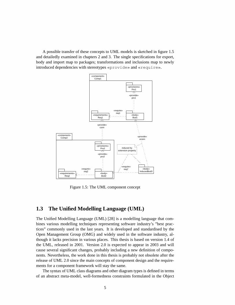
A possible transfer of these concepts to UML models is sketched in figure1.5and detailedly examined in chapters2 and3. The single specifications for export,body and import map to packages; transformations and inclusions map to newlyintroduced dependencies with stereotypes«provide» and«require» .
«component» Comp2
«component» Comp1
«provisions» Pro1
«requirements» Req1
«provisions» Pro2
«requirements» Req2
«provide» conn
«body» Bod1
«provide» pro1
«body» Bod2
«provide» pro2
«require» req1
«require» req2
«require» req1'
«provide» xconn
«body» InducedBod3
induced by extension property
Figure 1.5:The UML component concept
1.3 The Unified Modelling Language (UML)
The Unified Modelling Language (UML) [28] is a modelling language that com-bines various modelling techniques representing software industry’s ”best prac-tices” commonly used in the last years. It is developed and standardised by theOpen Management Group (OMG) and widely used in the software industry, al-though it lacks precision in various places. This thesis is based on version 1.4 ofthe UML, released in 2001. Version 2.0 is expected to appear in 2003 and willcause several significant changes, probably including a new definition of compo-nents. Nevertheless, the work done in this thesis is probably not obsolete after therelease of UML 2.0 since the main concepts of component design and the require-ments for a component framework will stay the same.
The syntax of UML class diagrams and other diagram types is defined in termsof an abstract meta-model, well-formedness constraints formulated in the Object
5
Constraint Language (OCL)2 and additional descriptions in English language. Thesemantics is informally defined in English language (and in some areas intention-ally left open). Additionally, a graphical notation and the mapping between con-crete notation and abstract syntax are specified.
1.3.1 The UML Meta-Model
This section gives a short introduction to the UML meta-model. Using the well-known class–instance relationship, the meta-model containsmeta-classes, instancesof which are UMLmodel elements.
-a
*
+b
0..1
asso
+op(in x)
A B
(a) Concrete notation
name = A
: Class
name = B
: Class
name = asso
: Association
participant
association
name = a isNavigable : Boolean = false multiplicity = * visibility = private
: AssociationEnd
connection name = b isNavigable : Boolean = true multiplicity = 0..1 visibility = public
: AssociationEnd
connection
participant
association
name = op visibility = public isQuery : Boolean = false
: Operation
feature owner
name = x kind = in
: Parameter
parameter
(b) Abstract syntax
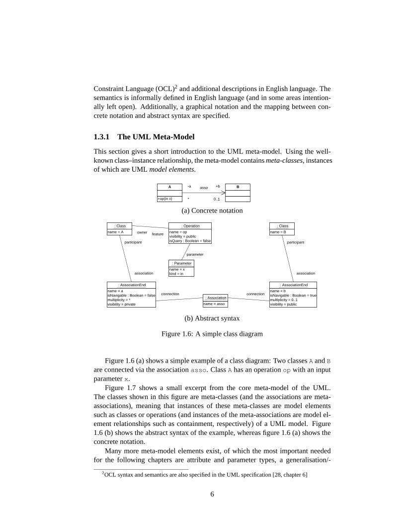
Figure 1.6:A simple class diagram
Figure1.6(a) shows a simple example of a class diagram: Two classesA andB
are connected via the associationasso . ClassA has an operationop with an inputparameterx .
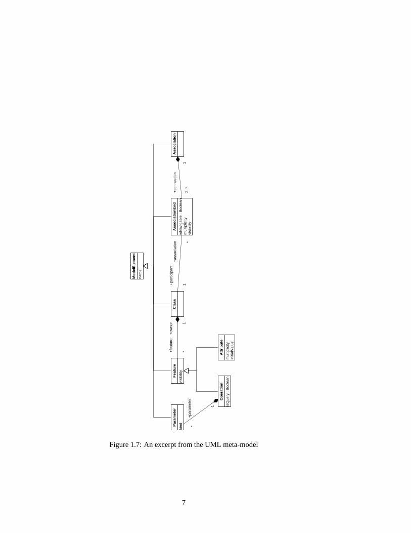
Figure 1.7 shows a small excerpt from the core meta-model of the UML.The classes shown in this figure are meta-classes (and the associations are meta-associations), meaning that instances of these meta-classes are model elementssuch as classes or operations (and instances of the meta-associations are model el-ement relationships such as containment, respectively) of a UML model. Figure1.6 (b) shows the abstract syntax of the example, whereas figure1.6 (a) shows theconcrete notation.
Many more meta-model elements exist, of which the most important neededfor the following chapters are attribute and parameter types, a generalisation/-
2OCL syntax and semantics are also specified in the UML specification [28, chapter 6]
6
Cla
ss
nam
e
Mo
del
Ele
men
t
Ass
oci
atio
n
isN
avig
able
: B
oole
an
mul
tiplic
ity
visi
bilit
y
Ass
oci
atio
nE
nd
visi
bilit
y
Fea
ture
mul
tiplic
ity
initi
alV
alue
Att
rib
ute
isQ
uery
: B
oole
an
Op
erat
ion
kind
Par
amet
er
+pa
ram
eter
*
1
+fe
atur
e
*
+ow
ner 1
+co
nnec
tion
* 1
2..*
+pa
rtic
ipan
t
1
+as
soci
atio
n *
Figure 1.7:An excerpt from the UML meta-model
7
<?xml version = ’1.0’ ?><XMI xmi.version = ’1.2’
xmlns:UML = ’org.omg.xmi.namespace.UML’><UML:Class xmi.id = ’a1’ name = ’A’>
<UML:Class.feature><UML:Operation xmi.id = ’a2’ name = ’op’
visibility = ’public’ isQuery = ’false’><UML:Operation.parameter>
<UML:Parameter xmi.id = ’a3’ name = ’x’kind = ’in’ />
</UML:Operation.parameter></UML:Operation>
</UML:Class.feature></UML:Class>
<UML:Class xmi.id = ’a4’ name = ’B’ />
<UML:Association xmi.id = ’a5’ name = ’asso’><UML:Association.connection>
<UML:AssociationEnd xmi.id = ’a6’ name = ’a’visibility = ’private’ isNavigable = ’false’><UML:AssociationEnd.participant>
<UML:Class xmi.idref = ’a1’/></UML:AssociationEnd.participant>
</UML:AssociationEnd><UML:AssociationEnd xmi.id = ’a7’ name = ’b’
visibility = ’public’ isNavigable = ’true’><UML:AssociationEnd.participant>
<UML:Class xmi.idref = ’a4’/></UML:AssociationEnd.participant>
</UML:AssociationEnd></UML:Association.connection>
</UML:Association></XMI>
Figure 1.8:XMI representation of the class diagram (simplified)
8
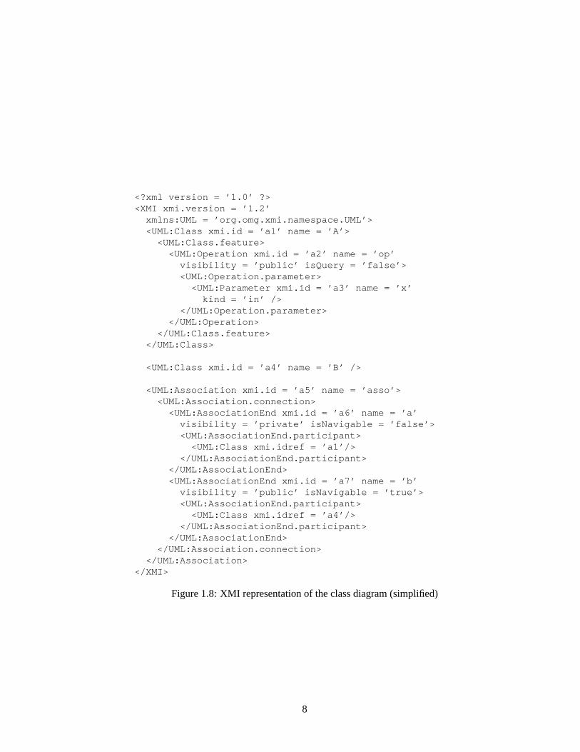
specialisation relationship, interfaces and packages.The abstract syntax can be stored in the standardised XML Metadata Inter-
change (XMI) format [15] and thus be interchanged between UML modellingtools. A simplified XMI file representing the example class diagram is given infigure 1.8. The model elements are represented by XML tags, their attributes byXML attributes, and the interrelations are represented by identifiers and references(xmi.id andxmi.idref tags). XMI does not store any graphical information,though, and thus only allows for the interchange of models, not of diagrams.
The UML is defined as one instance of the OMG Meta-Object Facility (MOF)meta-meta-model, which is an abstraction at an even higher level. The intentionof the MOF meta-meta-model is to make mappings between different modellingtechniques possible. Another instance of the MOF meta-meta-model, on the samelevel as the UML, is the OMG Interface Definition Language (IDL) specification.
1.4 Refinement and Similar Concepts
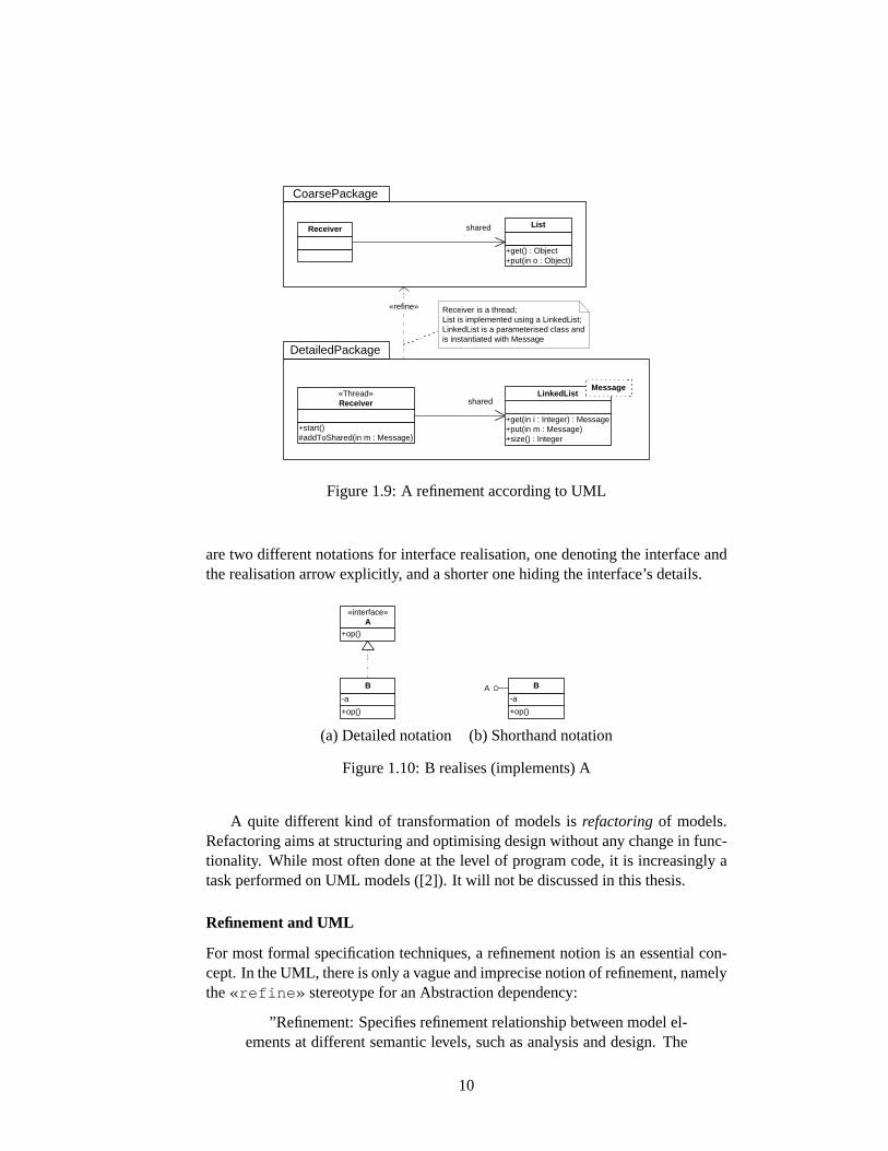
Refinement and similar concepts appear in different dimensions of software devel-opment and modelling. One dimension is the chain of development steps from aninitial requirements specification to an implementation (or an executable model),with (sub-)steps in between adding details, removing non-determinism and un-derspecification. Traditionally, this is a linear development (the infamouswater-fall process model), nowadays this is usually an iterative (or cyclic) development,meaning that earlier models can be changed, enhanced or corrected as soon as prob-lems are identified in models of a later phase. An example is given in figure1.9,where a coarse model is refined into a more detailed one, attached with a verbaljustification that this is a refinement.
The relation between refinements of this kind and the Generic ComponentFramework are shortly discussed in section4.3.
Another dimension is systemevolutionover time, i.e. adapting a system tochanged requirements, aimed at transforming the system into a consistent stateagain. This dimension has become more important in the last years as systemsbecame more open and more distributed, and thus were subject to changes moreoften than in a closed, clean ”world”. The key problem is to distinguish parts thatmust be changed from parts that can be left as they are, aimed at a minimum effortfor these changes.
The third dimension is the hiding of details of realising a service in a compo-nent body. Here, a refinement is a static relation in one model (in contrast to adevelopment over time and between different models as in the previous two cases).This dimension has a different meaning than the first one, but is structurally sim-ilar. A component body adds detail to the provisions specification and removesunderspecification from it. This kind of refinement is the essential one for thisthesis. A simple example is realising an interface by a class (figure1.10): The in-terface specifies operation signatures, the class defines an implementation. There
9
Receiver
+get() : Object +put(in o : Object)
List
+start() #addToShared(in m : Message)
«Thread» Receiver
shared
shared
«refine»
CoarsePackage
DetailedPackage
Receiver is a thread; List is implemented using a LinkedList; LinkedList is a parameterised class and is instantiated with Message
+get(in i : Integer) : Message +put(in m : Message) +size() : Integer
LinkedList Message
Figure 1.9:A refinement according to UML
are two different notations for interface realisation, one denoting the interface andthe realisation arrow explicitly, and a shorter one hiding the interface’s details.
+op()
«interface» A
+op()
-a
B A
+op()
-a
B
(a) Detailed notation (b) Shorthand notation
Figure 1.10:B realises (implements) A
A quite different kind of transformation of models isrefactoringof models.Refactoring aims at structuring and optimising design without any change in func-tionality. While most often done at the level of program code, it is increasingly atask performed on UML models ([2]). It will not be discussed in this thesis.
Refinement and UML
For most formal specification techniques, a refinement notion is an essential con-cept. In the UML, there is only a vague and imprecise notion of refinement, namelythe«refine» stereotype for an Abstraction dependency:
”Refinement: Specifies refinement relationship between model el-ements at different semantic levels, such as analysis and design. The
10
mapping specifies the relationship between the two elements or sets ofelements. The mapping may or may not be computable, and it maybe unidirectional or bidirectional. Refinement can be used to modeltransformations from analysis to design and other such changes” [28,section 2.5.2.1].
The level of formality of a refinement, though, depends on the concrete needs:
”The degree of rigor of this traceability is variable. In a criticalcontext, you can do these checks in mathematical detail. In more ordi-nary circumstances, you document the main points of correspondenceto guide reviewers and maintainers and use these points as the basisfor verification, design reviews, and testing.” [5, section 6.1]
In the UML, any two model elements of the same kind can be connected via adependency with a«refine» stereotype. Such a refinement can be used in anyof the refinement dimensions mentioned above, but it lacks precision.
In chapter2 a stricter form of refinement is defined, which, is still quite generaland usable in many different situations. The most common form of refinement inthe UML is class subtyping. On the syntactical level, this is an extension of fea-tures. Semantically, it has consequences on OCL constraints as well as behaviouralmodels.
The intention that services specified in one package are realised in anotherpackage can be broken down to a refinement of classes. Addition of detail meansaddition of classes, attributes and operations. Adding classes to an existing classdiagram implies a concept ofinclusionof packages. A package is refined by an-other package by adding model elements and modifying model elements usingsubtyping. Thus, package refinement can be expressed as an inclusion of packagecontents and defining subclasses. Details are discussed in section2.3.
1.5 Goals and Methods of the Thesis
In the following, a component concept for UML class diagrams shall be developedthat is built upon one developed in the IOSIP project (see chapter5) and that canbe proven to be an instantiation of the Generic Component Framework. The intentof this thesis is to provide a precise framework for this restricted part of the UML.As the full expressiveness can be gained only by using all diagram types, it is alsosketched how these can be integrated into the component framework.
In the next chapter, the instantiation is prepared by analysing the existing UMLmeans for including and refining models, by defining new, slightly stricter no-tions of inclusion and refinement, and finally by defining components. Chapter3shows that the defined component concept is an instantiation of the generic case,by proving transitivity and the extension property of transformations, and definingcomposition. Chapter4 sketches the needs for a component framework for thewhole UML, i.e. ideas how to integrate the other diagram types, where statechart
11
diagrams are examined more detailedly than the others. While chapters2 through4 use a ”toy size” running example (in the domain of bank accounts), chapter5applies the construct to parts of the IOSIP case study, allowing to prove usabilityof the concepts in a larger model (which is still not, of course, of realistic industrysize: the full IOSIP model consists of about 100 classes with about 30 statechartdiagrams). In chapter6 the component notion introduced in this thesis is discussedin the context of different UML-based component approaches.
As a notational convention all names of UML model elements as well as allOCL specifications are laid out ina typewriter font . Self-defined OCL func-tions (used much like ”Additional operations” in the UML specification [28]) areintroduced as needed and used from that point on. Some operations that are usedin various places are additionally given in appendixA.
12
Chapter 2
A Component Framework forUML Class Diagrams
2.1 Prerequisites
Throughout this and the next chapter, the focus will be set on UML class diagramsonly. First, a clarification has to made about the termclass diagram. UML modelsare based on an abstract syntax, as seen in section1.3.1, and diagrams are justthe visual notation that make UML models so understandable to a human. TheUML diagram types are not formally defined, in particular there is no meta-modelelement such asDiagram or ClassDiagram . There are only recommendationswhich model elements should be used in which diagram type: According to [28,section 3.19.2], a class diagram can contain ”static declarative model elements”,which in most cases means classifiers, relations and packages. Moreover, modelelements can be shown in multiple diagrams, and a single diagram can leave outmodel elements, if they are shown somewhere else. A complete UML model isalways thesum of all diagramsthat are claimed to be part of the model.
This is a most intuitive way of modelling, as it reflects the concept of differentviewsof a software system perfectly, and also reflects the idea ofdecomposingalarge model into parts. For the user of a modelling tool it is natural to browsethrough different pages and to ”zoom into” a package or a class, or to hide detailssuch as contents of a package or features of a class. On the other hand, it makesconsistency checks on diagrams, such as type checks or logical and behaviouralconstraints, almost impossible, because each diagram would have to be checkedwith regard to each other. This is why such checks are done at the abstract syntaxlevel, and why the component framework will not be defined for diagrams, but forthe abstract syntax.
13
2.1.1 Motivation for Packages as Component Parts
In section6.2the drawbacks of UML components as defined in [28, section 2.5.2.12]and used in many practical contexts will be discussed detailedly. One of thesedrawbacks is the fact that UML Components are limited to provide interfaces totheir environment. There is a need to provide more complex services, as will bemotivated now, and thuspackagesare chosen as component parts.
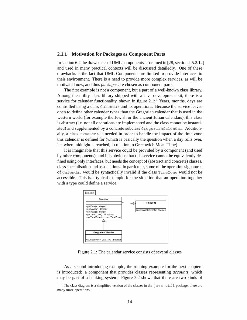
The first example is not a component, but a part of a well-known class library.Among the utility class library shipped with a Java development kit, there is aservice for calendar functionality, shown in figure2.1:1 Years, months, days arecontrolled using a classCalendar and its operations. Because the service leavesopen to define other calendar types than the Gregorian calendar that is used in thewestern world (for example the Jewish or the ancient Julian calendars), this classis abstract (i.e. not all operations are implemented and the class cannot be instanti-ated) and supplemented by a concrete subclassGregorianCalendar . Addition-ally, a classTimeZone is needed in order to handle the impact of the time zonethis calendar is defined for (which is basically the question when a day rolls over,i.e. when midnight is reached, in relation to Greenwich Mean Time).
It is imaginable that this service could be provided by a component (and usedby other components), and it is obvious that this service cannot be equivalently de-fined using only interfaces, but needs the concept of (abstract and concrete) classes,class specialisation and associations. In particular, some of the operation signaturesof Calendar would be syntactically invalid if the classTimeZone would not beaccessible. This is a typical example for the situation that an operation togetherwith a type could define a service.
java::util
+getDate() : Integer +getMonth() : Integer +getYear() : Integer +getTimeZone() : TimeZone +setTimeZone(in zone : TimeZone)
Calendar
+useDaylightTime() : Boolean
TimeZone
+isLeapYear(in year : int) : Boolean
GregorianCalendar
Figure 2.1:The calendar service consists of several classes
As a second introducing example, the running example for the next chaptersis introduced: a component that provides classes representingaccounts, whichmay be part of a banking system. Figure2.2 shows that there are two kinds of
1The class diagram is a simplified version of the classes in thejava.util package; there aremany more operations.
14

accounts, namely cheque accounts and savings accounts. A standard feature ofobject-oriented modelling is making use ofgeneralisation: For some parts of thesystem the kind of an account may be irrelevant, they only need to know of ac-counts in general. By adding a superclassAccount , client objects may link toaccount objects without knowing the concrete runtime type of the object, but stilltype-safely with regard to the operation signatures ofAccount , namely operationsfor retrieving the account number and the balance, and for depositing and with-drawing given amounts of money. This example will be extended as new conceptsare introduced, but already in this excerpt it is more intuitive to provide this classdiagram to the environment, than providing only three interfaces without showingtheir interrelations.
+getNumber() : Integer +getBalance() : Integer +deposit(in amount : Integer) +withdraw(in amount : Integer)
Account
ChequeAccount
+calculateInterest()
SavingsAccount
Figure 2.2:Two kinds of accounts
With packages chosen as component parts, the question rises which existingor new UML techniques to use as refinement transformations and inclusions asdemanded by the Generic Framework. This is examined in the next two sections.
2.2 Inclusion of Packages
In [9] the relation between a component body and a component import is charac-terised as follows:
”We assume that the import connection is some kind of inclusion,in the sense that the functionality defined in the body is built upon theimport interface.”
Although there is no notion of inclusion of packages in the UML, there is aclosely related construct calledimport. This section will shed some light on theUML import’s difficulties.
The motivation for the inclusion is that functionality that is needed in a com-ponent part is realised elsewhere. This functionality can be given, for example,by a single operation. In figure2.3 (a) a«uses» dependency (informally) indi-
15
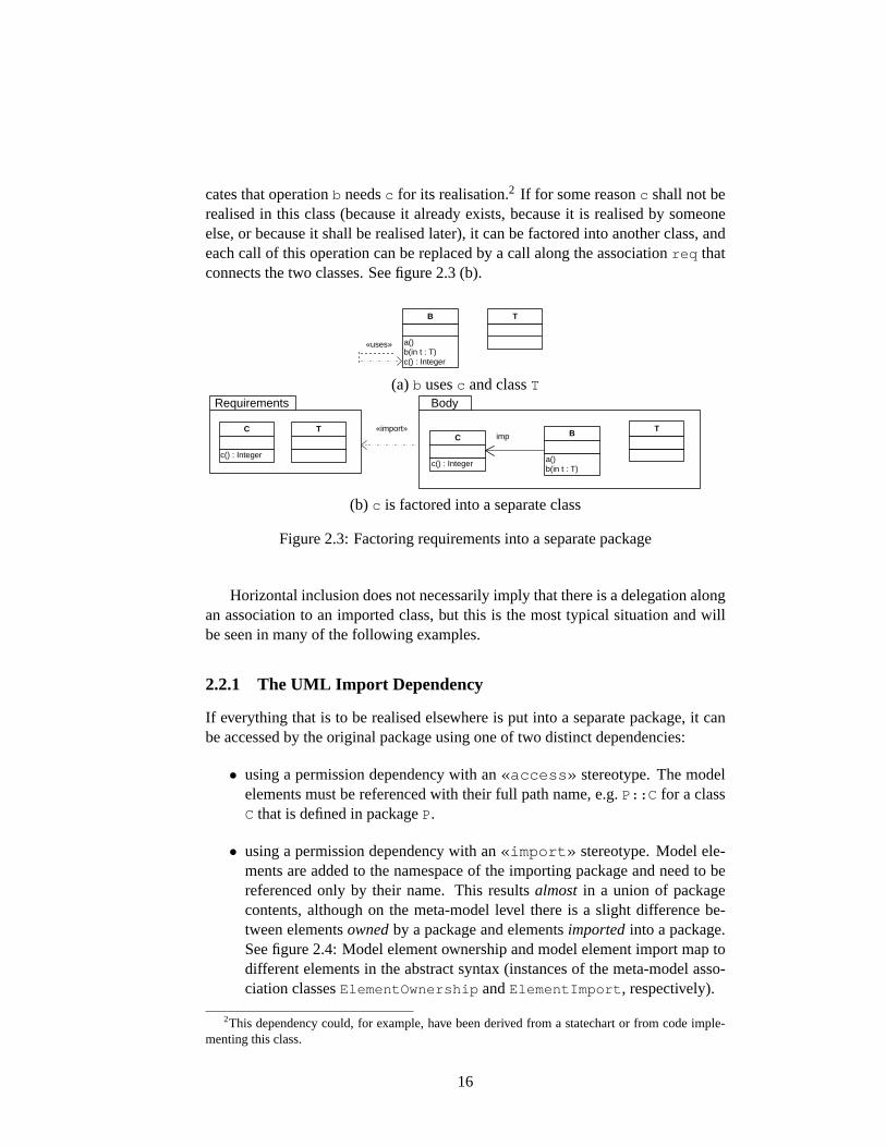
cates that operationb needsc for its realisation.2 If for some reasonc shall not berealised in this class (because it already exists, because it is realised by someoneelse, or because it shall be realised later), it can be factored into another class, andeach call of this operation can be replaced by a call along the associationreq thatconnects the two classes. See figure2.3(b).
a() b(in t : T) c() : Integer
B T
«uses»
(a) b usesc and classT
a() b(in t : T)
B T
c() : Integer
C imp T
c() : Integer
C
Body Requirements
«import»
(b) c is factored into a separate class
Figure 2.3:Factoring requirements into a separate package
Horizontal inclusion does not necessarily imply that there is a delegation alongan association to an imported class, but this is the most typical situation and willbe seen in many of the following examples.
2.2.1 The UML Import Dependency
If everything that is to be realised elsewhere is put into a separate package, it canbe accessed by the original package using one of two distinct dependencies:
• using a permission dependency with an«access» stereotype. The modelelements must be referenced with their full path name, e.g.P::C for a classC that is defined in packageP.
• using a permission dependency with an«import» stereotype. Model ele-ments are added to the namespace of the importing package and need to bereferenced only by their name. This resultsalmost in a union of packagecontents, although on the meta-model level there is a slight difference be-tween elementsownedby a package and elementsimportedinto a package.See figure2.4: Model element ownership and model element import map todifferent elements in the abstract syntax (instances of the meta-model asso-ciation classesElementOwnership andElementImport , respectively).
2This dependency could, for example, have been derived from a statechart or from code imple-menting this class.
16
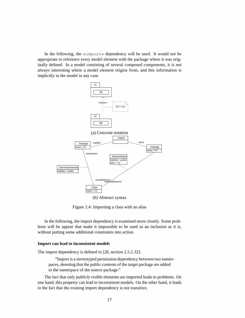
In the following, the«import» dependency will be used. It would not beappropriate to reference every model element with the package where it was orig-inally defined. In a model consisting of several composed components, it is notalways interesting where a model element origins from, and this information isimplicitly in the model in any case.
P2
P1
«import»
C1
C2
[C2 / C1]
(a) Concrete notation
name = P1
: Package
name = P2
: Package
name = C1
: Class
client
: Import
visibility = public alias = C2
: ElementImport
supplier
visibility = public
: ElementOwnership
namespace
ownedElement importedElement
(b) Abstract syntax
Figure 2.4:Importing a class with an alias
In the following, the import dependency is examined more closely. Some prob-lems will be appear that make it impossible to be used as an inclusion as it is,without putting some additional constraints into action.
Import can lead to inconsistent models
The import dependency is defined in [28, section 2.5.2.32]:
”Import is a stereotyped permission dependency between two names-paces, denoting that the public contents of the target package are addedto the namespace of the source package.”
The fact that onlypublicly visibleelements are imported leads to problems. Onone hand, this property can lead to inconsistent models. On the other hand, it leadsto the fact that the existing import dependency is not transitive.
17
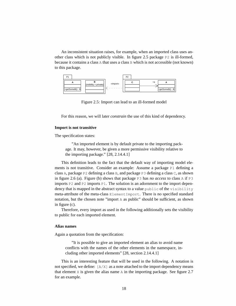
An inconsistent situation raises, for example, when an imported class uses an-other class which is not publicly visible. In figure2.5 packageP2 is ill-formed,because it contains a classA that uses a classB which is not accessible (not known)to this package.
P2 P1
+getSomeB() : B
A B {visibility = private}
C +a
+getSomeB() : B
A «import»
Figure 2.5:Import can lead to an ill-formed model
For this reason, we will laterconstrainthe use of this kind of dependency.
Import is not transitive
The specification states:
”An imported element is by default private to the importing pack-age. It may, however, be given a more permissive visibility relative tothe importing package.” [28, 2.14.4.1]
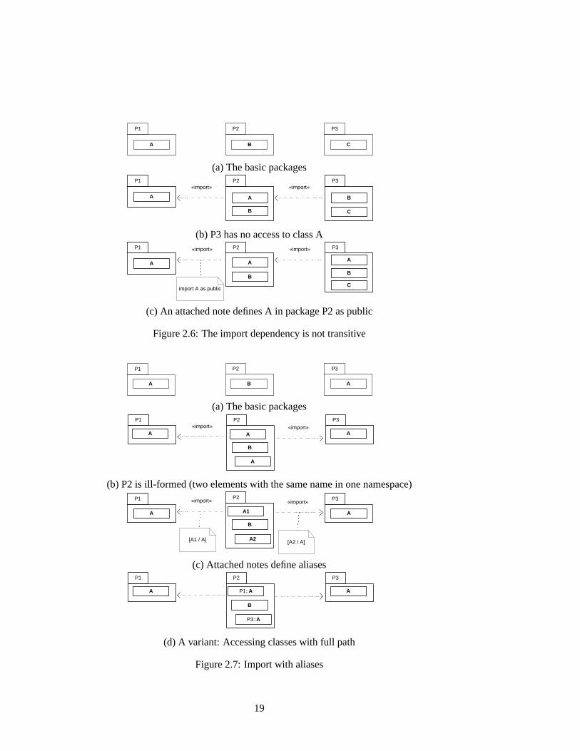
This definition leads to the fact that the default way of importing model ele-ments is not transitive. Consider an example: Assume a packageP1 defining aclassA, packageP2 defining a classB, and packageP3 defining a classC, as shownin figure2.6 (a). Figure (b) shows that packageP3 hasno accessto classA if P3
importsP2 andP2 importsP1. The solution is an adornment to the import depen-dency that is mapped in the abstract syntax to a valuepublic of thevisibility
meta-attribute of the meta-classElementImport . There is no specified standardnotation, but the chosen note ”importA as public” should be sufficient, as shownin figure (c).
Therefore, every import as used in the following additionally sets the visibilityto public for each imported element.
Alias names
Again a quotation from the specification:
”It is possible to give an imported element an alias to avoid nameconflicts with the names of the other elements in the namespace, in-cluding other imported elements” [28, section 2.14.4.1]
This is an interesting feature that will be used in the following. A notation isnot specified, we define:[A/X] as a note attached to the import dependency meansthat elementX is given the alias nameA in the importing package. See figure2.7for an example.
18
P1
A
P2 P3
B C
(a) The basic packagesP1 P2 P3
A A
B
B
C
«import» «import»
(b) P3 has no access to class AP1 P2 P3
A
B
A A
B
C
«import» «import»
import A as public
(c) An attached note defines A in package P2 as public
Figure 2.6:The import dependency is not transitive
P2 P3
B A A
P1
(a) The basic packagesP1 P2 P3
«import» «import» A A A
B
A
(b) P2 is ill-formed (two elements with the same name in one namespace)P2 P1 P3 «import» «import»
A A
B
[A1 / A] [A2 / A]
A1
A2
(c) Attached notes define aliasesP1 P2 P3
B
A A P1:: A
P3:: A
(d) A variant: Accessing classes with full path
Figure 2.7:Import with aliases
19
Avoiding Name Clashes
Whenever an import is used, name conflicts can appear. The well-formedness rulesof a package say that there may not be two model elements with the same namein a package, including imported elements. If such a situation exists, the model isill-formed. One can imagine different possibilities to avoid name clashes betweenan importing and an imported package:
• Name clashes are detected by the modelling tool immediately when a modelelement or an import dependency is added. The user must choose a differentname.
• The tool automatically defines a unique alias name for an imported element(like ModelElement25 )
• The full path of a model element must be used, e.g.P::C
For simplicity, in the following name conflict freeness is required. Therefore,a function is defined that checks for name clashes between two packages.
Definition 2.2.1 (Name Conflict Freeness).Two packagesA andB arename con-flict free, if there are no owned elements with the same name inA andB. In OCL:
let isNameConflictFree(A:Package, B:Package):Boolean =A->ownedElement->forAll( a:ModelElement |
not B->ownedElement->exists(b:ModelElement | a.name = b.name))
This definition is not concerned about name conflicts in imported elements.This is explained now.
Rhombic import
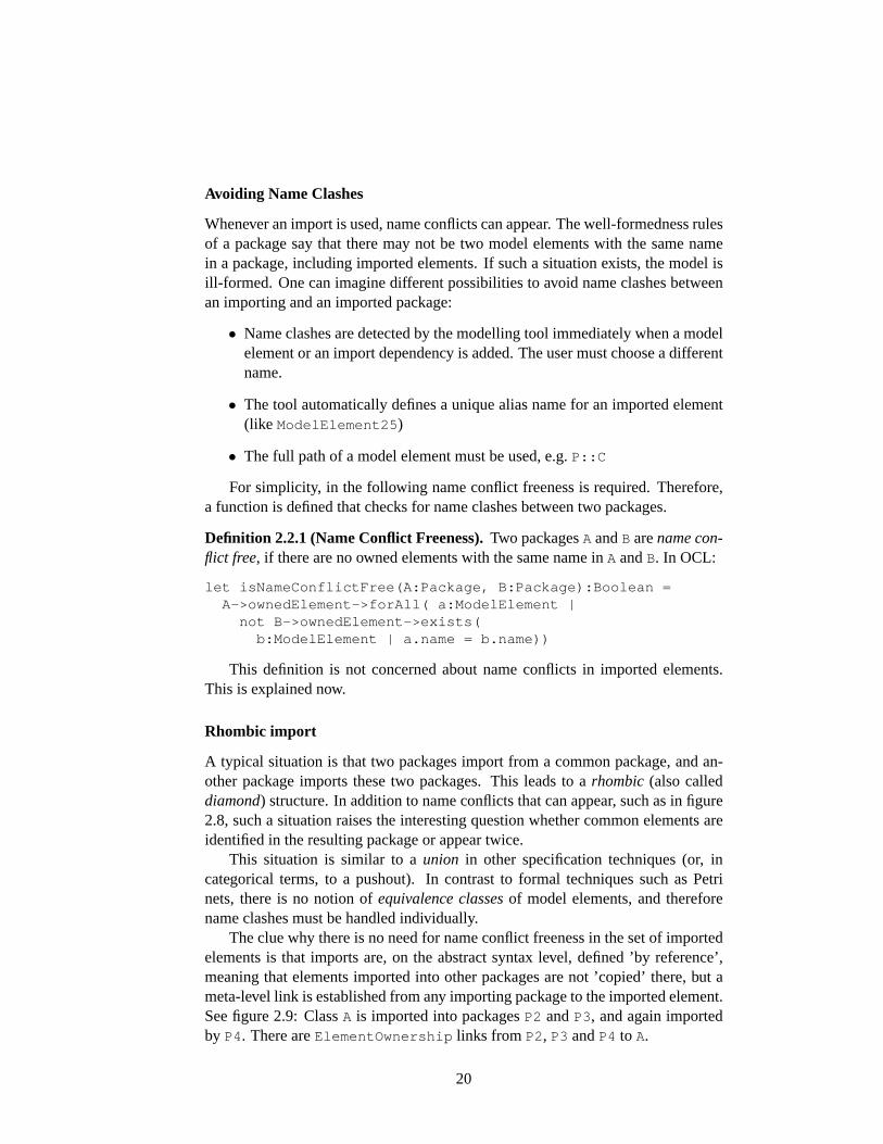
A typical situation is that two packages import from a common package, and an-other package imports these two packages. This leads to arhombic (also calleddiamond) structure. In addition to name conflicts that can appear, such as in figure2.8, such a situation raises the interesting question whether common elements areidentified in the resulting package or appear twice.
This situation is similar to aunion in other specification techniques (or, incategorical terms, to a pushout). In contrast to formal techniques such as Petrinets, there is no notion ofequivalence classesof model elements, and thereforename clashes must be handled individually.
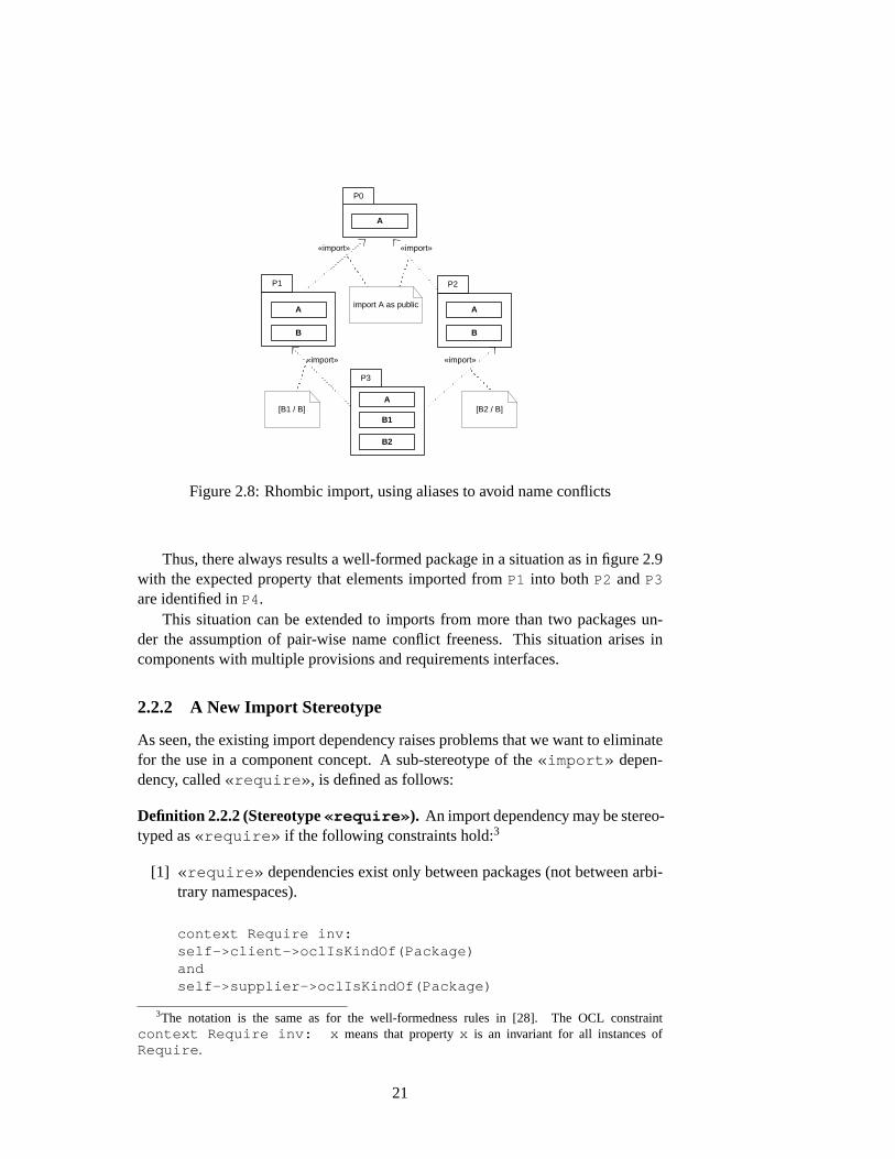
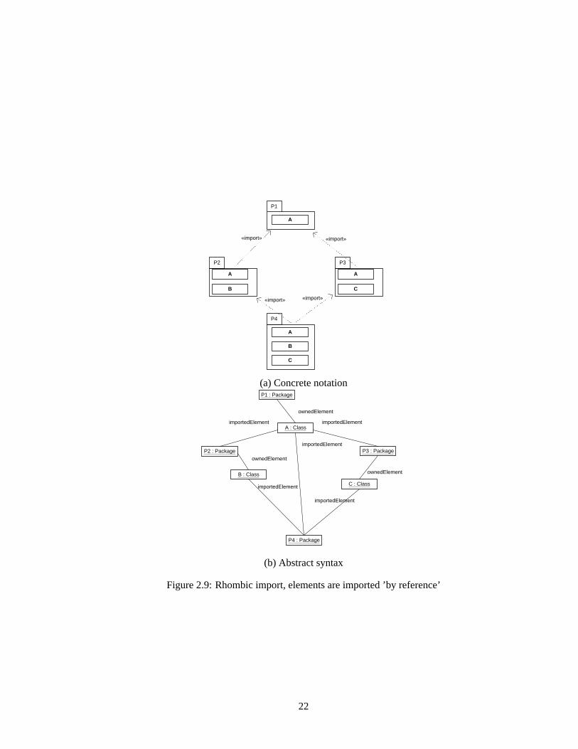
The clue why there is no need for name conflict freeness in the set of importedelements is that imports are, on the abstract syntax level, defined ’by reference’,meaning that elements imported into other packages are not ’copied’ there, but ameta-level link is established from any importing package to the imported element.See figure2.9: ClassA is imported into packagesP2 andP3, and again importedby P4. There areElementOwnership links from P2, P3 andP4 to A.
20
P0
P2
A
A
B
P1
«import» «import»
A
B
P3
A
B1
B2
«import» «import»
[B2 / B] [B1 / B]
import A as public
Figure 2.8:Rhombic import, using aliases to avoid name conflicts
Thus, there always results a well-formed package in a situation as in figure2.9with the expected property that elements imported fromP1 into bothP2 andP3
are identified inP4.This situation can be extended to imports from more than two packages un-
der the assumption of pair-wise name conflict freeness. This situation arises incomponents with multiple provisions and requirements interfaces.
2.2.2 A New Import Stereotype
As seen, the existing import dependency raises problems that we want to eliminatefor the use in a component concept. A sub-stereotype of the«import» depen-dency, called«require» , is defined as follows:
Definition 2.2.2 (Stereotype«require» ). An import dependency may be stereo-typed as«require» if the following constraints hold:3
[1] «require» dependencies exist only between packages (not between arbi-trary namespaces).
context Require inv:self->client->oclIsKindOf(Package)andself->supplier->oclIsKindOf(Package)
3The notation is the same as for the well-formedness rules in [28]. The OCL constraintcontext Require inv: x means that propertyx is an invariant for all instances ofRequire .
21
P3 P2
A
P1
B
A A
C
A
B
C
P4
«import» «import»
«import» «import»
(a) Concrete notation
P4 : Package
P3 : Package P2 : Package
P1 : Package
A : Class
B : Class
C : Class
ownedElement
ownedElement
ownedElement
importedElement importedElement
importedElement
importedElement
importedElement
(b) Abstract syntax
Figure 2.9:Rhombic import, elements are imported ’by reference’
22
[2] Every element in the imported package is public.
let allPublic(p:Package):Boolean =p.elementOwnership[ownedElement]->visibility = public
context Require inv:allPublic(self->supplier)
[3] Every element is imported as public into the importing package.
let allImportsPublic(importing:Package,imported:Package):Boolean =importing.elementImport[importedElement]->select(me:ModelElement | me.namespace = imported )->visibility = public
context Require inv:allImportsPublic(self->client, self->supplier)
[4] No generalisations from the importing (body) to the imported (requirements)package exist.
let existsGeneralization(from:Package, to:Package):Boolean =from->ownedElement->exists(
ch:GeneralizableElement | to->ownedElement->exists(par:GeneralizableElement | isSpecialisation(ch,par)
))context Require inv:not existsGeneralization(self->client, self->supplier)
Using this stereotype, a notion of inclusion of packages in the sense of [9] canbe defined, see section3.1.
2.3 Refinement of Classes and Packages
The justification associated with a refinement canbe formal or informal; it could even simply say,’Joe said this will work’.[5, section 6.9]
Refinement relations are often missing completely in the UML practice, or usedad-hoc and implicitly, maybe even without recognising that a refinement relationexists. The authors of [5], which is a book mainly for practitioners, state that it isalready an improvement if such refinement relations are recognised, made explicit,and attached with some justification.
In this section a very simple refinement concept for packages is developed,based on a simple notion of refinement of classes, which is compatible with themost typical uses of the UML. These refinement definitions could be replaced bydifferent, especially by more formal ones if desired, where most of the componentconcept could stay the same. “Plugging in” other refinement notions implies, ofcourse, an appropriate proof of the extension property for this refinement definition.
23
2.3.1 Refinement of Classes
As sketched in section1.4, very different notions of refinement in the UML exist.Instead of choosing some of these and defining them formally, in the following themost basic refinement concept of object-oriented modelling,inheritance, is usedas the foundation for refinement of classes. First, it shall be discussed whetherthis common usage of UML classes reflects what we expect from a refinementrelation. There are very different definitions of refinement, but as a common sense,the following characterisations and requirements apply usually:
• In a refinement relationship the refining model is more concrete, more de-tailedly specified and more deterministic. The refined model is less concrete,less detailedly specified and more non-deterministic.
• The refinement relation is reflexive, transitive and anti-symmetric (i.e. it de-fines a partial order).4
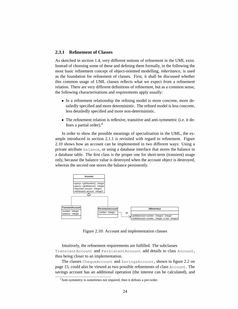
In order to show the possible meanings of specialisation in the UML, the ex-ample introduced in section2.1.1 is revisited with regard to refinement. Figure2.10shows how an account can be implemented in two different ways: Using aprivate attributebalance , or using a database interface that stores the balance ina database table. The first class is the proper one for short-term (transient) usageonly, because the balance value is destroyed when the account object is destroyed,whereas the second one stores the balance persistently.
«query» +getNumber() : Integer «query» +getBalance() : Integer +deposit(in amount : Integer) +withdraw(in amount : Integer)
Account
-number : Integer
PersistentAccount
+getBalance(in number : Integer) : Integer +setBalance(in number : Integer, in bal : Integer)
DBInterface
db -number : Integer -balance : Integer
TransientAccount
Figure 2.10:Account and implementation classes
Intuitively, the refinement requirements are fulfilled. The subclassesTransientAccount andPersistentAccount add details to classAccount ,thus being closer to an implementation.
The classesChequeAccount andSavingsAccount , shown in figure2.2 onpage15, could also be viewed as two possible refinements of classAccount . Thesavings account has an additional operation (the interest can be calculated), and
4Anti-symmetry is sometimes not required, then it defines a pre-order.
24
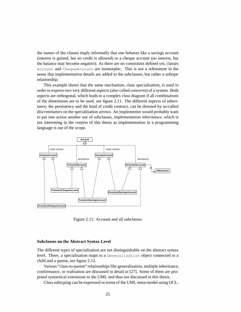
the names of the classes imply informally that one behaves like a savings account(interest is gained, but no credit is allowed) or a cheque account (no interest, butthe balance may become negative). As there are no constraints defined yet, classesAccount andChequeAccount are isomorphic. This isnot a refinement in thesense that implementation details are added in the subclasses, but rather asubtyperelationship.
This example shows that the same mechanism, class specialisation, is used inorder to express two very differentaspects(also calledconcerns) of a system. Bothaspects are orthogonal, which leads to a complex class diagram if all combinationsof the dimensions are to be used, see figure2.11. The different aspects of inheri-tance, the persistency and the kind of credit contract, can be denoted by so-calleddiscriminatorson the specialisation arrows. An implementor would probably wantto put into action another use of subclasses,implementation inheritance, which isnot interesting in the context of this thesis as implementation in a programminglanguage is out of the scope.
Account
ChequeAccount SavingsAccount
TransientAccount PersistentAccount
DBInterface db
TransientChequeAccount
PersistentChequeAccount
TransientSavingsAccount
PersistentSavingsAccount
persistency
credit contract
persistency
credit contract
Figure 2.11:Account and all subclasses
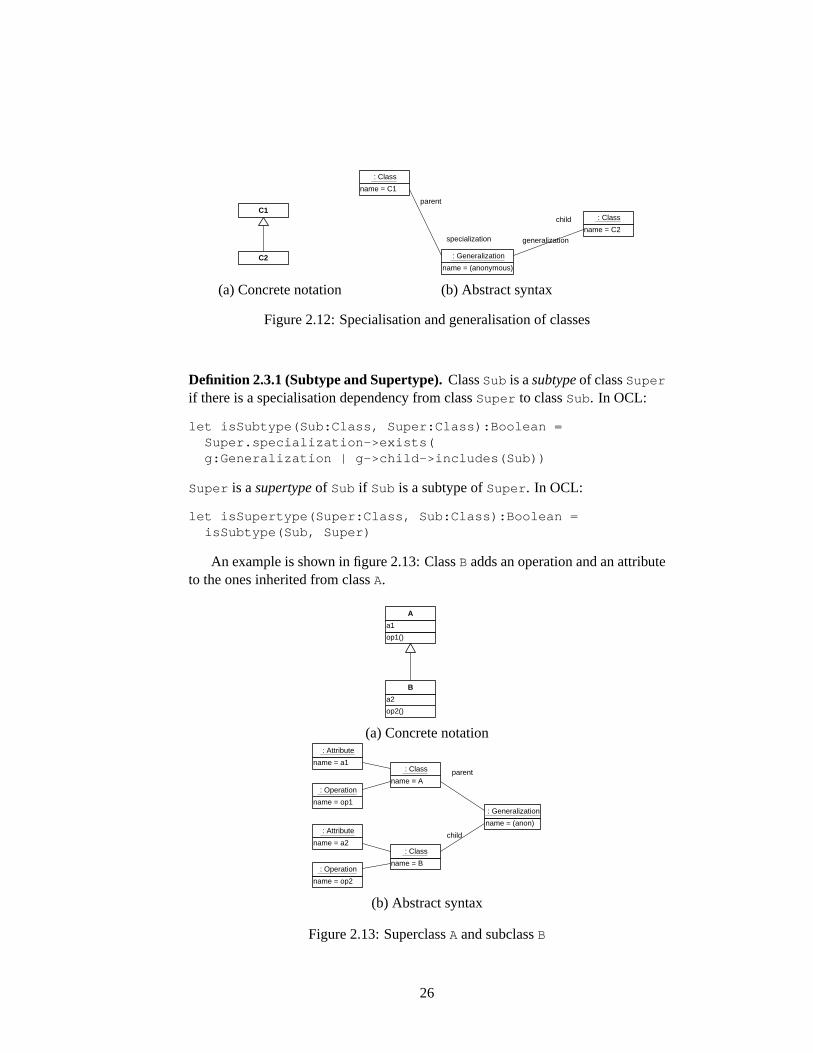
Subclasses on the Abstract Syntax Level
The different types of specialisation are not distinguishable on the abstract syntaxlevel. There, a specialisation maps to aGeneralization object connected to achild and a parent, see figure2.12.
Various ”class-to-parent” relationships like generalisation, multiple inheritance,conformance, or realisation are discussed in detail in [27]. Some of them are pro-posed syntactical extensions to the UML and thus not discussed in this thesis.
Class subtyping can be expressed in terms of the UML meta-model using OCL.
25
C2
C1
name = (anonymous)
: Generalization
name = C1
: Class
name = C2
: Class
parent
specialization generalization
child
(a) Concrete notation (b) Abstract syntax
Figure 2.12:Specialisation and generalisation of classes
Definition 2.3.1 (Subtype and Supertype).ClassSub is asubtypeof classSuper
if there is a specialisation dependency from classSuper to classSub. In OCL:
let isSubtype(Sub:Class, Super:Class):Boolean =Super.specialization->exists(g:Generalization | g->child->includes(Sub))
Super is asupertypeof Sub if Sub is a subtype ofSuper . In OCL:
let isSupertype(Super:Class, Sub:Class):Boolean =isSubtype(Sub, Super)
An example is shown in figure2.13: ClassB adds an operation and an attributeto the ones inherited from classA.
op1()
a1
A
op2()
a2
B
(a) Concrete notation
name = A
: Class
name = B
: Class
name = a1
: Attribute
name = a2
: Attribute name = (anon)
: Generalization
parent
child
name = op1
: Operation
name = op2
: Operation
(b) Abstract syntax
Figure 2.13:SuperclassA and subclassB
26

But classes are not the only model element that can be refined this way: In-terfaces, associations, association classes and several other model elements aresubclasses ofGeneralizableElement in the meta-model. Thus, the definitioncan be extended to all generalisable (and thus also specialisable) model elements.Meta-classes that are subtypes ofGeneralizableElement includeClassifier ,Association , Package , Stereotype , Class , Interface , Usecase , andActor .
One additional situation which is not a generalisation/specialisation relation-ship in the meta-model, has a similar meaning and is important and often used:Realisation of an interface. A class can realise one or more interfaces (see fig-ure1.10on page10), which means that the operations defined in the interface areimplemented by the class (or a subclass). Interface realisation is, on the abstractsyntax level, an Abstraction dependency stereotyped with«realize» .
Definition 2.3.2 (Specialisation and Generalisation).A generalisable elementSpec is aspecialisationof a generalisable elementGen if there is a specialisationdependency fromGen to Spec , or Gen is an interface realised bySpec . In OCL:
let isSpecialisation(Spec:GeneralizableElement,Gen:GeneralizableElement):Boolean =
Gen.specialization->exists(g:Generalization| g->child->includes(Spec))
orGen.supplierDependency->exists(r:Realization
| r->client->includes(Spec))
Gen is ageneralisationof Spec if Spec is a specialisation ofGen. In OCL:
let isGeneralisation(Gen:GeneralizableElement,Spec:GeneralizableElement):Boolean =
isSpecialisation(Spec, Gen)
2.3.2 Excursus: Formalisation in Set Theory
Subtyping can also be expressed in terms of set theory. Heavily simplifying, classesconsist of a name and features, and subtyping is just adding features. The termssegment descriptorand full descriptorof a class are used in [28] in order to de-scribe classes and subtyping, but they are not mathematically defined. The formaldescriptor is the description of a class collecting all information from the super-classes, and is needed when instantiating a class (i.e. creating an object). A for-malisation of a class, given the setsname for all class names andattrs andopnsfor all attribute and operation specifications, respectively, could be:
Definition 2.3.3 (Segment Descriptor).The segment descriptor of a classC con-sists of a name, attributes and operations:5
5It is not distinguished between attributes and associations ends at the opposite end of an associ-ation.
27
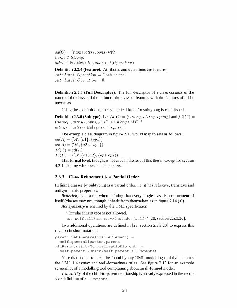
sd(C) = (name, attrs, opns) withname ∈ String,attrs ∈ P(Attribute), opns ∈ P(Operation)
Definition 2.3.4 (Feature). Attributes and operations are features.Attribute ∪Operation = Feature andAttribute ∩Operation = ∅
Definition 2.3.5 (Full Descriptor). The full descriptor of a class consists of thename of the class and the union of the classes’ features with the features of all itsancestors.
Using these definitions, the syntactical basis for subtyping is established.
Definition 2.3.6 (Subtype).Letfd(C) = (nameC , attrsC , opnsC) andfd(C ′) =(nameC′ , attrsC′ , opnsC′). C ′ is asubtypeof C ifattrsC ⊆ attrsC′ andopnsC ⊆ opnsC′ .
The example class diagram in figure2.13would map to sets as follows:sd(A) = (′A′, {a1}, {op1})sd(B) = (′B′, {a2}, {op2})fd(A) = sd(A)fd(B) = (′B′, {a1, a2}, {op1, op2})
This formal level, though, is not used in the rest of this thesis, except for section4.2.1, dealing with protocol statecharts.
2.3.3 Class Refinement is a Partial Order
Refining classes by subtyping is a partial order, i.e. it has reflexive, transitive andantisymmetric properties.
Reflexivityis ensured when defining that every single class is a refinement ofitself (classes may not, though, inherit from themselves as in figure2.14(a)).
Antisymmetryis ensured by the UML specification:
”Circular inheritance is not allowed.not self.allParents->includes(self) ” [ 28, section 2.5.3.20].
Two additional operations are defined in [28, section 2.5.3.20] to express thisrelation in short notation:
parent:Set(GeneralizableElement) =self.generalization.parent
allParents:Set(GeneralizableElement) =self.parent->union(self.parent.allParents)
Note that such errors can be found by any UML modelling tool that supportsthe UML 1.4 syntax and well-formedness rules. See figure2.15 for an examplescreenshot of a modelling tool complaining about an ill-formed model.
Transitivityof the child-to-parent relationship is already expressed in the recur-sive definition ofallParents .
28
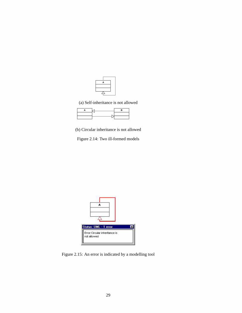
A
(a) Self-inheritance is not allowed
B A
(b) Circular inheritance is not allowed
Figure 2.14:Two ill-formed models
Figure 2.15:An error is indicated by a modelling tool
29
2.3.4 OCL and Refinement
Class diagrams without constraints define only structure, no behaviour. In particu-lar, operations that are not constrained can return arbitrary results and manipulateits classes’ attributes arbitrarily.
Any UML model can be constrained by attaching constraints to one or moremodel elements. These constraints can in principle be given in any (including nat-ural) language, but the appropriate way of constraining models precisely is to usethe Object Constraint Language (OCL, [28, chapter 6]). Defining behaviour withstatechart diagrams, as well as the relation between these two kinds of constrainingclasses, will be examined in section4.2.
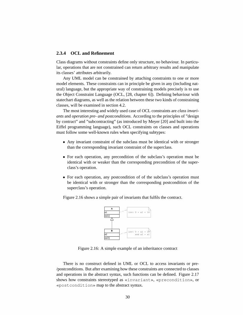
The most interesting and widely used case of OCL constraints areclass invari-antsandoperation pre- and postconditions. According to the principles of ”designby contract” and ”subcontracting” (as introduced by Meyer [20] and built into theEiffel programming language), such OCL constraints on classes and operationsmust follow some well-known rules when specifying subtypes:
• Any invariant constraint of the subclass must be identical with or strongerthan the corresponding invariant constraint of the superclass.
• For each operation, any precondition of the subclass’s operation must beidentical with or weaker than the corresponding precondition of the super-class’s operation.
• For each operation, any postcondition of of the subclass’s operation mustbe identical with or stronger than the corresponding postcondition of thesuperclass’s operation.
Figure2.16shows a simple pair of invariants that fulfils the contract.
op1()
a1
A
op2()
a2
B
inv: 0 < a1 < 10
inv: 0 < a1 < 10 and a2 > a1
Figure 2.16:A simple example of an inheritance contract
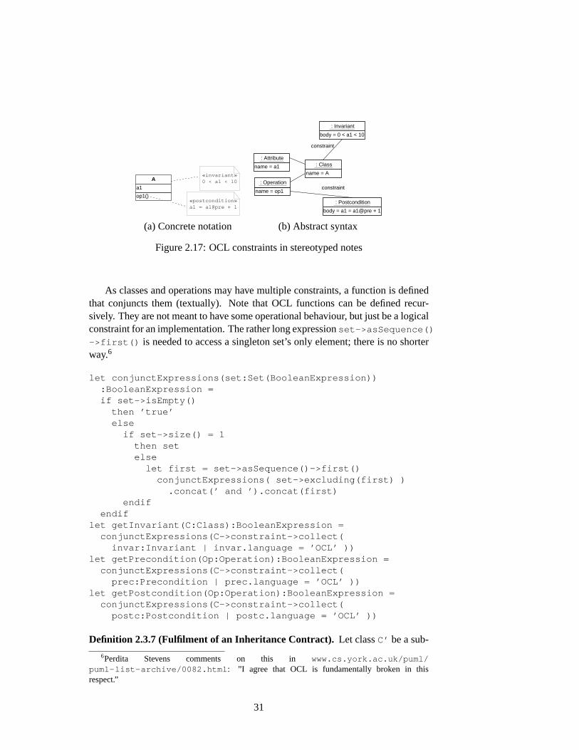
There is no construct defined in UML or OCL to access invariants or pre-/postconditions. But after examining how these constraints are connected to classesand operations in the abstract syntax, such functions can be defined. Figure2.17shows how constraints stereotyped as«invariant» , «precondition» , or«postcondition» map to the abstract syntax.
30
op1()
a1
A «invariant» 0 < a1 < 10
«postcondition» a1 = a1@pre + 1
name = A
: Class
body = 0 < a1 < 10
: Invariant
name = op1
: Operation
name = a1
: Attribute
constraint
body = a1 = a1@pre + 1
: Postcondition
constraint
(a) Concrete notation (b) Abstract syntax
Figure 2.17:OCL constraints in stereotyped notes
As classes and operations may have multiple constraints, a function is definedthat conjuncts them (textually). Note that OCL functions can be defined recur-sively. They are not meant to have some operational behaviour, but just be a logicalconstraint for an implementation. The rather long expressionset->asSequence()
->first() is needed to access a singleton set’s only element; there is no shorterway.6
let conjunctExpressions(set:Set(BooleanExpression)):BooleanExpression =if set->isEmpty()
then ’true’else
if set->size() = 1then setelse
let first = set->asSequence()->first()conjunctExpressions( set->excluding(first) )
.concat(’ and ’).concat(first)endif
endiflet getInvariant(C:Class):BooleanExpression =
conjunctExpressions(C->constraint->collect(invar:Invariant | invar.language = ’OCL’ ))
let getPrecondition(Op:Operation):BooleanExpression =conjunctExpressions(C->constraint->collect(
prec:Precondition | prec.language = ’OCL’ ))let getPostcondition(Op:Operation):BooleanExpression =
conjunctExpressions(C->constraint->collect(postc:Postcondition | postc.language = ’OCL’ ))
Definition 2.3.7 (Fulfilment of an Inheritance Contract). Let classC’ be a sub-
6Perdita Stevens comments on this in www.cs.york.ac.uk/puml/puml-list-archive/0082.html : ”I agree that OCL is fundamentally broken in thisrespect.”
31
class ofC. The two classesfulfil their inheritance contract, ifgetInvariant(C’) =⇒getInvariant(C)
For all operationsop in C:getPrecondition(C::op()) =⇒getPrecondition(C’::op())
For all operationsop in C:getPostcondition(C’::op()) =⇒getPostcondition(C::op())
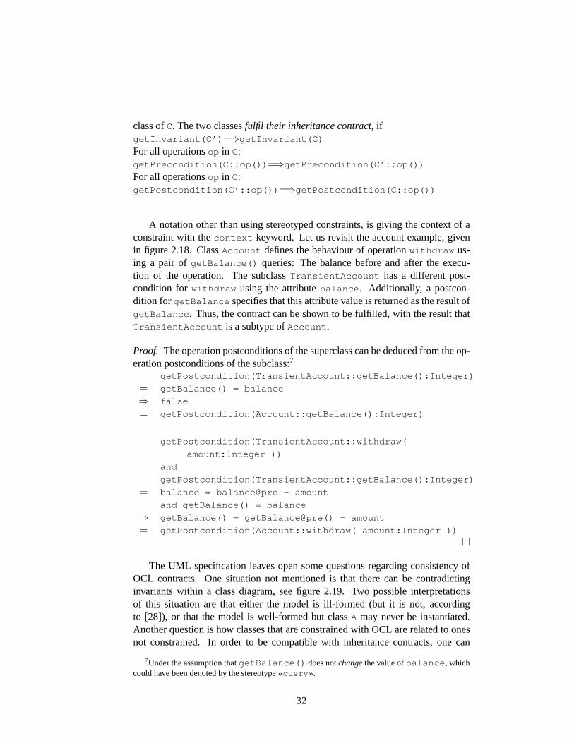
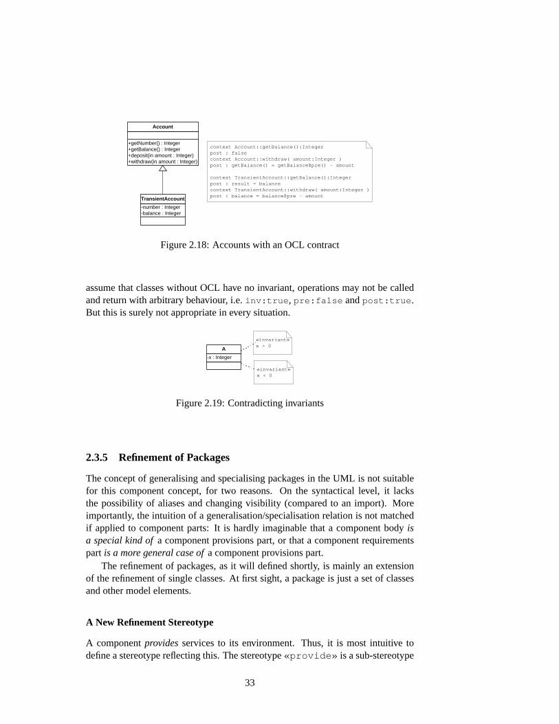
A notation other than using stereotyped constraints, is giving the context of aconstraint with thecontext keyword. Let us revisit the account example, givenin figure2.18. ClassAccount defines the behaviour of operationwithdraw us-ing a pair ofgetBalance() queries: The balance before and after the execu-tion of the operation. The subclassTransientAccount has a different post-condition for withdraw using the attributebalance . Additionally, a postcon-dition for getBalance specifies that this attribute value is returned as the result ofgetBalance . Thus, the contract can be shown to be fulfilled, with the result thatTransientAccount is a subtype ofAccount .
Proof. The operation postconditions of the superclass can be deduced from the op-eration postconditions of the subclass:7
getPostcondition(TransientAccount::getBalance():Integer)
= getBalance() = balance
⇒ false
= getPostcondition(Account::getBalance():Integer)
getPostcondition(TransientAccount::withdraw(
amount:Integer ))
and
getPostcondition(TransientAccount::getBalance():Integer)
= balance = balance@pre - amount
and getBalance() = balance
⇒ getBalance() = getBalance@pre() - amount
= getPostcondition(Account::withdraw( amount:Integer ))
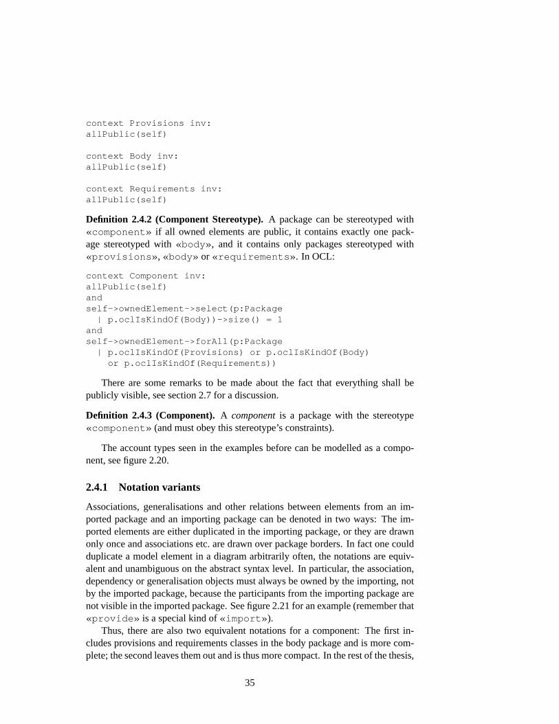
The UML specification leaves open some questions regarding consistency ofOCL contracts. One situation not mentioned is that there can be contradictinginvariants within a class diagram, see figure2.19. Two possible interpretationsof this situation are that either the model is ill-formed (but it is not, accordingto [28]), or that the model is well-formed but classA may never be instantiated.Another question is how classes that are constrained with OCL are related to onesnot constrained. In order to be compatible with inheritance contracts, one can
7Under the assumption thatgetBalance() does notchangethe value ofbalance , whichcould have been denoted by the stereotype«query» .
32
+getNumber() : Integer +getBalance() : Integer +deposit(in amount : Integer) +withdraw(in amount : Integer)
Account
-number : Integer -balance : Integer
TransientAccount
context Account::getBalance():Integer post : false context Account::withdraw( amount:Integer ) post : getBalance() = getBalance@pre() - amount
context TransientAccount::getBalance():Integer post : result = balance context TransientAccount::withdraw( amount:Integer ) post : balance = balance@pre - amount
Figure 2.18:Accounts with an OCL contract
assume that classes without OCL have no invariant, operations may not be calledand return with arbitrary behaviour, i.e.inv:true , pre:false andpost:true .But this is surely not appropriate in every situation.
-x : Integer
A
«invariant» x > 0
«invariant» x < 0
Figure 2.19:Contradicting invariants
2.3.5 Refinement of Packages
The concept of generalising and specialising packages in the UML is not suitablefor this component concept, for two reasons. On the syntactical level, it lacksthe possibility of aliases and changing visibility (compared to an import). Moreimportantly, the intuition of a generalisation/specialisation relation is not matchedif applied to component parts: It is hardly imaginable that a component bodyisa special kind ofa component provisions part, or that a component requirementspart is a more general case ofa component provisions part.
The refinement of packages, as it will defined shortly, is mainly an extensionof the refinement of single classes. At first sight, a package is just a set of classesand other model elements.
A New Refinement Stereotype
A componentprovidesservices to its environment. Thus, it is most intuitive todefine a stereotype reflecting this. The stereotype«provide» is a sub-stereotype
33

of both Import and Refinement. This is syntactically legal ([28, 2.6.4]) and reflectsthe intuition that we want.
Definition 2.3.8 (Stereotype«provide» ). An abstraction dependency may bestereotyped as«provide» if the following constraints hold:
[1] «provide» dependencies exist only between packages (not between arbi-trary namespaces).
context Provide inv:self->client->oclIsKindOf(Package)andself->supplier->oclIsKindOf(Package)
[2] Every element in the refined (abstract) package is public.
context Provide inv:allPublic(self->supplier)
[3] Every element is imported as public into the refining (concrete) package.
context Provide inv:allImportsPublic(self->client, self->supplier)
[4] No generalisations from the refined (abstract) to the refining (concrete) pack-age exist.
context Provide inv:not existsGeneralization(self->supplier, self->client)
A refinement transformation of the same kind arises when connecting two com-ponents.
This stereotype can be used to define refinement transformations of packagesin the sense of [9], this is done in section3.1. A different, stricter definition ofrefinement of packages is shortly discussed in section2.7
2.4 Components
Components will now be defined, using stereotypes for packages. The purposeof the stereotypes is twofold: On one hand, they are a notation convention thathelps to oversee a large diagram ’at first sight’. On the other hand, they force thepackages to fulfil constraints that are needed for the compositionality results in thenext chapter.
Definition 2.4.1 (Provisions, Body, Requirements Stereotypes).A package canbe stereotyped with«provisions» , «body» or«requirements» if all ownedelements are public. In OCL:
34
context Provisions inv:allPublic(self)
context Body inv:allPublic(self)
context Requirements inv:allPublic(self)
Definition 2.4.2 (Component Stereotype).A package can be stereotyped with«component» if all owned elements are public, it contains exactly one pack-age stereotyped with«body» , and it contains only packages stereotyped with«provisions» , «body» or «requirements» . In OCL:
context Component inv:allPublic(self)andself->ownedElement->select(p:Package
| p.oclIsKindOf(Body))->size() = 1andself->ownedElement->forAll(p:Package
| p.oclIsKindOf(Provisions) or p.oclIsKindOf(Body)or p.oclIsKindOf(Requirements))
There are some remarks to be made about the fact that everything shall bepublicly visible, see section2.7for a discussion.
Definition 2.4.3 (Component). A componentis a package with the stereotype«component» (and must obey this stereotype’s constraints).
The account types seen in the examples before can be modelled as a compo-nent, see figure2.20.
2.4.1 Notation variants
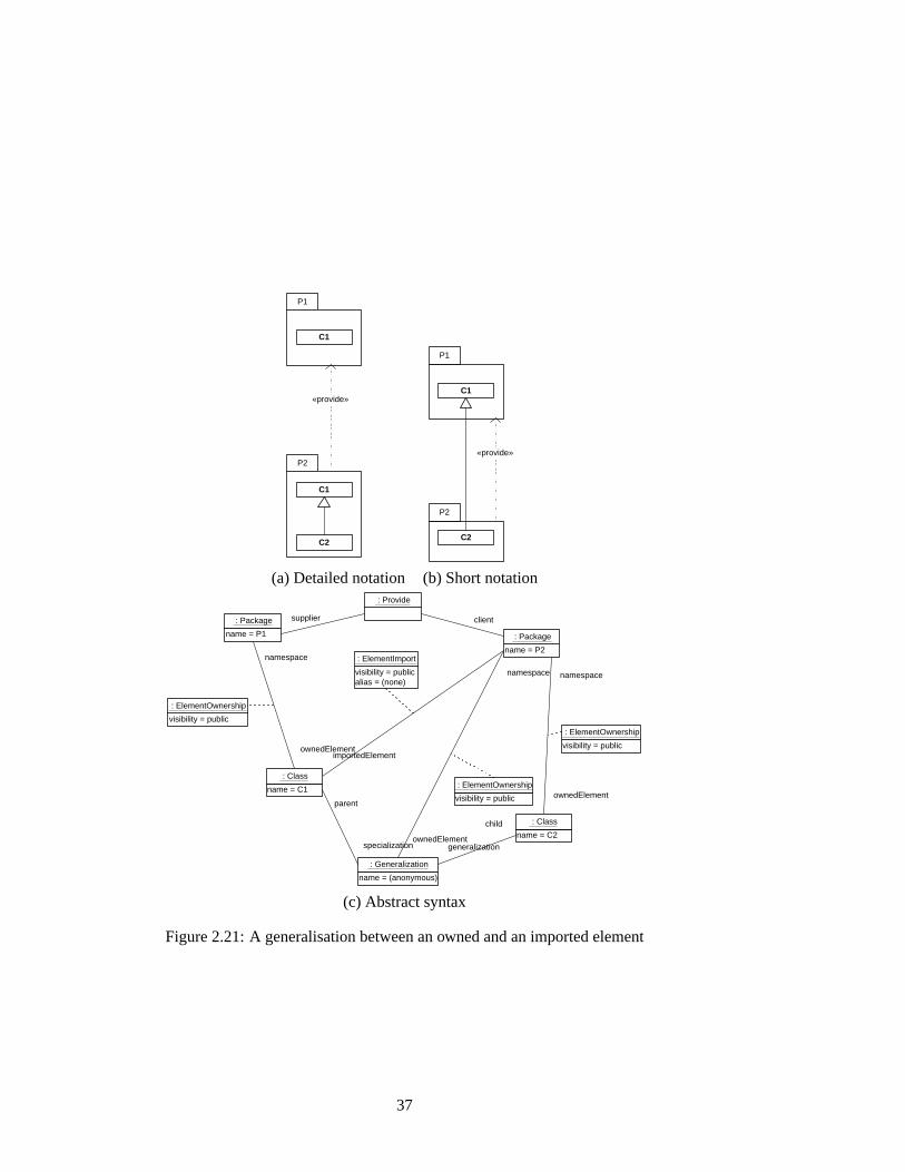
Associations, generalisations and other relations between elements from an im-ported package and an importing package can be denoted in two ways: The im-ported elements are either duplicated in the importing package, or they are drawnonly once and associations etc. are drawn over package borders. In fact one couldduplicate a model element in a diagram arbitrarily often, the notations are equiv-alent and unambiguous on the abstract syntax level. In particular, the association,dependency or generalisation objects must always be owned by the importing, notby the imported package, because the participants from the importing package arenot visible in the imported package. See figure2.21for an example (remember that«provide» is a special kind of«import» ).
Thus, there are also two equivalent notations for a component: The first in-cludes provisions and requirements classes in the body package and is more com-plete; the second leaves them out and is thus more compact. In the rest of the thesis,
35

«com
pone
nt»
Acc
ount
ing
«pro
vide
»
«pro
visi
ons»
A
ccou
nts «b
ody»
A
ccou
ntsI
mpl
emen
tatio
n
«req
uire
men
ts»
Per
sist
ency
Acc
ou
nt
Acc
ou
ntF
acto
ry
Ch
equ
eAcc
ou
nt
Sav
ing
sAcc
ou
nt
Acc
ou
nt
Ch
equ
eAcc
ou
nt
Sav
ing
sAcc
ou
nt
Per
sist
entA
cco
un
t T
ran
sien
tAcc
ou
nt
Acc
ou
ntF
acto
ry
Per
sist
entC
heq
ueA
cco
un
t
Per
sist
entS
avin
gsA
cco
un
t Tra
nsi
entS
avin
gsA
cco
un
t Tra
nsi
entC
heq
ueA
cco
un
t D
BIn
terf
ace
db
DB
Inte
rfac
e
«req
uire
»
Figure 2.20:The accounting component
36
P2
P1
«provide»
C1
C2
C1
P2
P1
«provide»
C1
C2
(a) Detailed notation (b) Short notation
namespace
ownedElement
name = (anonymous)
: Generalization
name = P1
: Package
name = P2
: Package
name = C1
: Class
client
: Provide
visibility = public alias = (none)
: ElementImport
supplier
visibility = public
: ElementOwnership
name = C2
: Class
visibility = public
: ElementOwnership
parent
specialization generalization
child
importedElement
namespace
ownedElement
visibility = public
: ElementOwnership
namespace
ownedElement
(c) Abstract syntax
Figure 2.21:A generalisation between an owned and an imported element
37
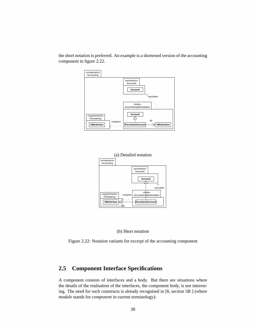
the short notation is preferred. An example is a shortened version of the accountingcomponent in figure2.22.
«component» Accounting
«provisions» Accounts
«body» AccountsImplementation
«requirements» Persistency
Account
Account
PersistentAccount DBInterface
db
DBInterface
«provide»
«require»
(a) Detailed notation
«body» AccountsImplementation
«provide»
«component» Accounting
«provisions» Accounts
«requirements» Persistency
Account
DBInterface PersistentAccount
db
«require»
(b) Short notation
Figure 2.22:Notation variants for excerpt of the accounting component
2.5 Component Interface Specifications
A component consists of interfaces and a body. But there are situations wherethe details of the realisation of the interfaces, the component body, is not interest-ing. The need for such constructs is already recognised in [8, section 5B ] (wheremodulestands forcomponentin current terminology):
38
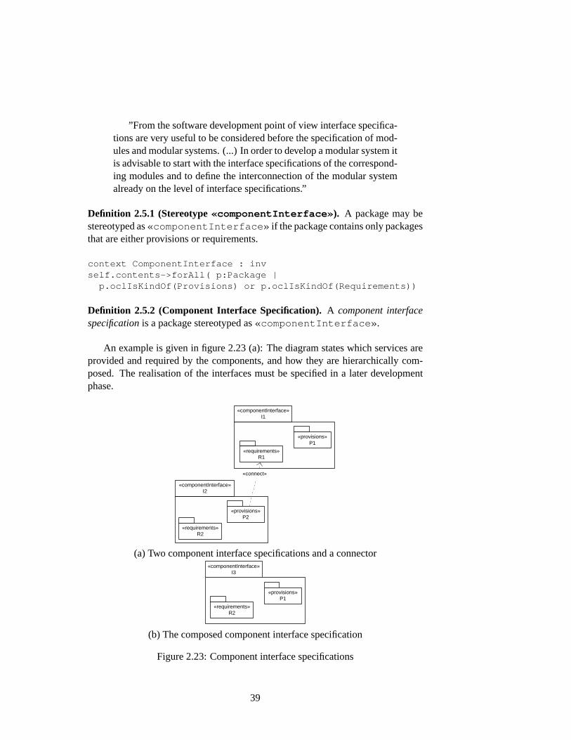
”From the software development point of view interface specifica-tions are very useful to be considered before the specification of mod-ules and modular systems. (...) In order to develop a modular system itis advisable to start with the interface specifications of the correspond-ing modules and to define the interconnection of the modular systemalready on the level of interface specifications.”
Definition 2.5.1 (Stereotype«componentInterface» ). A package may bestereotyped as«componentInterface» if the package contains only packagesthat are either provisions or requirements.
context ComponentInterface : invself.contents->forAll( p:Package |
p.oclIsKindOf(Provisions) or p.oclIsKindOf(Requirements))
Definition 2.5.2 (Component Interface Specification).A component interfacespecificationis a package stereotyped as«componentInterface» .
An example is given in figure2.23(a): The diagram states which services areprovided and required by the components, and how they are hierarchically com-posed. The realisation of the interfaces must be specified in a later developmentphase.
«componentInterface» I2
«componentInterface» I1
«provisions» P1
«requirements» R1
«provisions» P2
«requirements» R2
«connect»
(a) Two component interface specifications and a connector«componentInterface»
I3
«provisions» P1
«requirements» R2
(b) The composed component interface specification
Figure 2.23:Component interface specifications
39
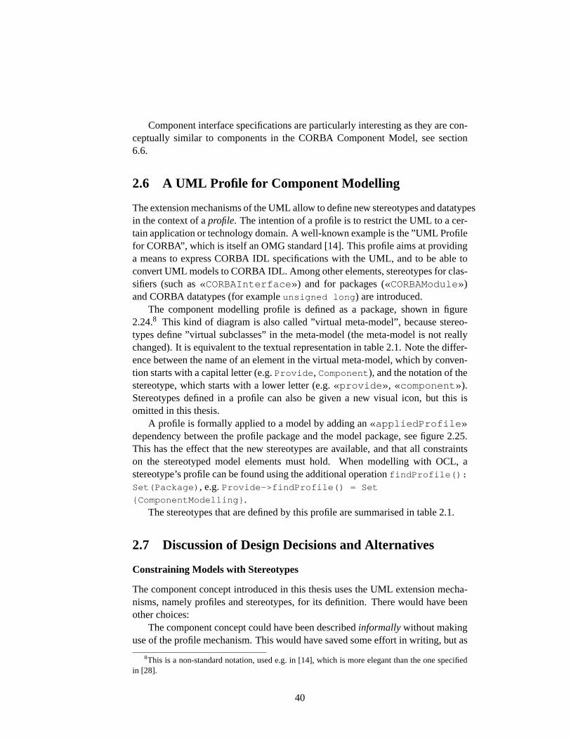
Component interface specifications are particularly interesting as they are con-ceptually similar to components in the CORBA Component Model, see section6.6.
2.6 A UML Profile for Component Modelling
The extension mechanisms of the UML allow to define new stereotypes and datatypesin the context of aprofile. The intention of a profile is to restrict the UML to a cer-tain application or technology domain. A well-known example is the ”UML Profilefor CORBA”, which is itself an OMG standard [14]. This profile aims at providinga means to express CORBA IDL specifications with the UML, and to be able toconvert UML models to CORBA IDL. Among other elements, stereotypes for clas-sifiers (such as«CORBAInterface» ) and for packages («CORBAModule»)and CORBA datatypes (for exampleunsigned long ) are introduced.
The component modelling profile is defined as a package, shown in figure2.24.8 This kind of diagram is also called ”virtual meta-model”, because stereo-types define ”virtual subclasses” in the meta-model (the meta-model is not reallychanged). It is equivalent to the textual representation in table2.1. Note the differ-ence between the name of an element in the virtual meta-model, which by conven-tion starts with a capital letter (e.g.Provide , Component ), and the notation of thestereotype, which starts with a lower letter (e.g.«provide» , «component» ).Stereotypes defined in a profile can also be given a new visual icon, but this isomitted in this thesis.
A profile is formally applied to a model by adding an«appliedProfile»dependency between the profile package and the model package, see figure2.25.This has the effect that the new stereotypes are available, and that all constraintson the stereotyped model elements must hold. When modelling with OCL, astereotype’s profile can be found using the additional operationfindProfile():
Set(Package) , e.g.Provide->findProfile() = Set
{ComponentModelling} .The stereotypes that are defined by this profile are summarised in table2.1.
2.7 Discussion of Design Decisions and Alternatives
Constraining Models with Stereotypes
The component concept introduced in this thesis uses the UML extension mecha-nisms, namely profiles and stereotypes, for its definition. There would have beenother choices:
The component concept could have been describedinformallywithout makinguse of the profile mechanism. This would have saved some effort in writing, but as
8This is a non-standard notation, used e.g. in [14], which is more elegant than the one specifiedin [28].
40

«profile» ComponentModelling
«stereotype» Provisions
Model Management::Package
Core::Abstraction Core::Permission
«stereotype» Core::Refinement
«stereotype» Core::Import
«baseElement»
«baseElement» «baseElement»
Core::Dependency
«stereotype» Requirements
«stereotype» Component
«baseElement» «baseElement»
«stereotype» Body
«baseElement»
«stereotype» Provide
«stereotype» Require
«stereotype» ComponentInterface
«baseElement»
Figure 2.24:Component modelling profile
System
«appliedProfile»
«profile» ComponentModelling
«component» Comp1
«component» Comp2 «component»
Comp3
Figure 2.25:Application of a profile
41
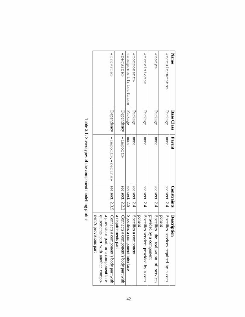
Nam
eB
aseC
lassP
arentC
onstraintsD
escription«
req
uire
me
nts»
Package
nonesee
sect.2.4S
pecifiesservices
requiredby
acom
-ponent
«b
od
y»P
ackagenone
seesect.2.4
Specifies
therealisation
ofservices
providedby
acom
ponent«
pro
vision
s»P
ackagenone
seesect.2.4
Specifies
servicesprovided
bya
com-
ponent«
com
po
ne
nt»
Package
nonesee
sect.2.4S
pecifiesa
component
«co
mp
on
en
tInte
rface
»P
ackagenone
seesect.2.5
Specifies
acom
ponentinterface«
req
uire
»D
ependency«
imp
ort»
seesect.2.2.2
Connects
acom
ponent’sbody
partwith
arequirem
entspart
«p
rovid
e»
Dependency
«im
po
rt»,«
refin
e»
seesect.2.3.5
Connects
acom
ponent’sbody
partwith
aprovisions
part,or
acom
ponent’sre-
quirements
partw
ithanother
compo-
nent’sprovisions
part
Table2.1:S
tereotypesofthe
componentm
odellingprofile
42
the relation between the existing UML specification would be unclear and possiblyimprecise, hardly any existing modelling tool could be extended to deal with sucha description.
Similarly, the existing semantics of UML model elements could have beenaltered, e.g. by saying ”from now on, each import dependency sets visibility aspublic”. This is an absolutely inappropriate approach because it would lead toconfusion among modellers, it would induce incompatibilities between models de-signed within and outside this framework, and would clearly contradict the UMLspecification (which is, not to forget, a standard used widely in software industry).
New meta-model elements, especially a meta-classComponent could havebeen added to the UML specification, together with its own well-formedness rulesand its own semantics specification. This was not done because substantial effortwould arise to develop tools that handle the new constructs. Such extensions arereferred to in [28] as ’heavy-weight’ extensions that are possible in principle ow-ing to the MOF meta-meta-model, whereas using profiles and stereotypes, withoutaltering the meta-model, is called ’light-weight’ extension.
Summarising, choosing the UML extension mechanisms was the right thing todo with respect to a possible tool assistance. But it is another question whether thedefinitions introduced are suitable from the point of view ofusability in softwaredesign. First, one has to realise that the semantic impact of stereotypes is limited:
”A fundamental constraint on all extensions defined using the pro-file extension mechanism is that extensions must be strictly additive tothe standard UML semantics. This means that such extensions mustnot conflict with or contradict the standard semantics. In effect, theseextension mechanisms are a means for refining the standard semanticsof UML and do not support arbitrary semantic extension.” [28, section2.6.1]
In my opinion, the restrictions imposed by the stereotypes do not restrict mod-els very strictly. Most of the constraints are concerned with visibility and con-sistency of naming. One detail that is probably one of the most discussable isthat the need to define all package contents publicly visiblebreaks encapsulation.Granted, but this is a simplification chosen in order to have a simple definitionof consistency of refinements and inclusions. One could imagine more flexibilityin this area, but this would imply a stricter and probably more complicated com-patibility definition, because careless use of import arrows can lead to ill-formedmodels (section2.2.1). The intuition of visibility in component modelling is dif-ferent from the one in programming. Component body parts are ’invisible’ to theuser of a component; the interface parts of are component must always be visiblecompletely. The UML specification also notes that visibility is a minor problem onthe modelling level ([28, p. 3-45]): ”Actually all forms of nonpublic visibility arelanguage-dependent”.
The only constraint that really restricts the expressiveness of UML is the pro-hibition of generalisations from a provisions part to a body part. But this restric-
43
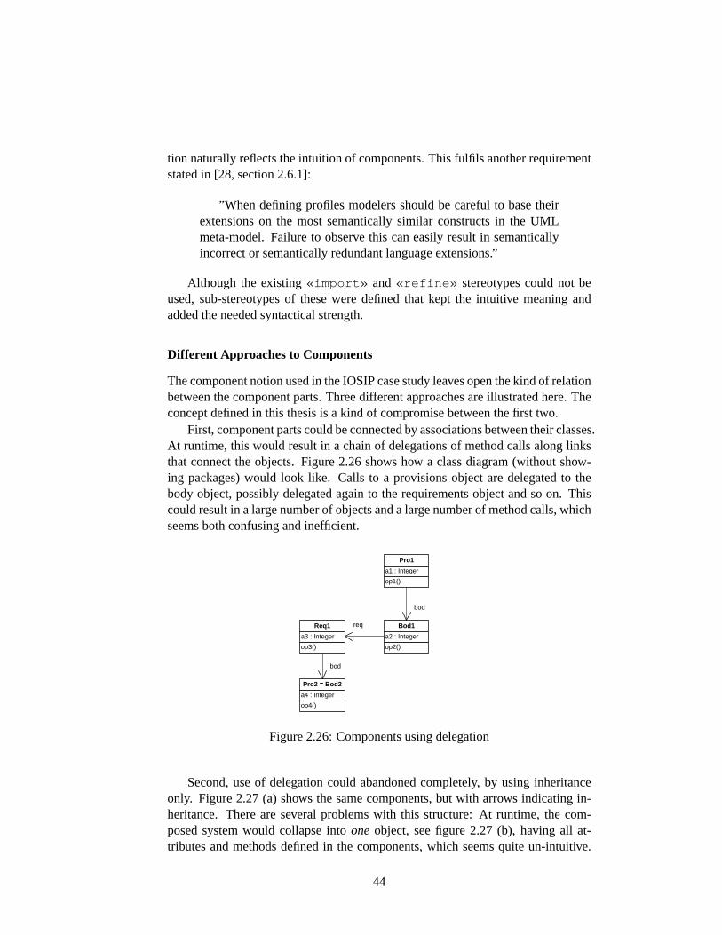
tion naturally reflects the intuition of components. This fulfils another requirementstated in [28, section 2.6.1]:
”When defining profiles modelers should be careful to base theirextensions on the most semantically similar constructs in the UMLmeta-model. Failure to observe this can easily result in semanticallyincorrect or semantically redundant language extensions.”
Although the existing«import» and«refine» stereotypes could not beused, sub-stereotypes of these were defined that kept the intuitive meaning andadded the needed syntactical strength.
Different Approaches to Components
The component notion used in the IOSIP case study leaves open the kind of relationbetween the component parts. Three different approaches are illustrated here. Theconcept defined in this thesis is a kind of compromise between the first two.
First, component parts could be connected by associations between their classes.At runtime, this would result in a chain of delegations of method calls along linksthat connect the objects. Figure2.26shows how a class diagram (without show-ing packages) would look like. Calls to a provisions object are delegated to thebody object, possibly delegated again to the requirements object and so on. Thiscould result in a large number of objects and a large number of method calls, whichseems both confusing and inefficient.
op1()
a1 : Integer
Pro1
op3()
a3 : Integer
Req1
op2()
a2 : Integer
Bod1
op4()
a4 : Integer
Pro2 = Bod2
bod
req
bod
Figure 2.26:Components using delegation
Second, use of delegation could abandoned completely, by using inheritanceonly. Figure2.27(a) shows the same components, but with arrows indicating in-heritance. There are several problems with this structure: At runtime, the com-posed system would collapse intooneobject, see figure2.27 (b), having all at-tributes and methods defined in the components, which seems quite un-intuitive.
44
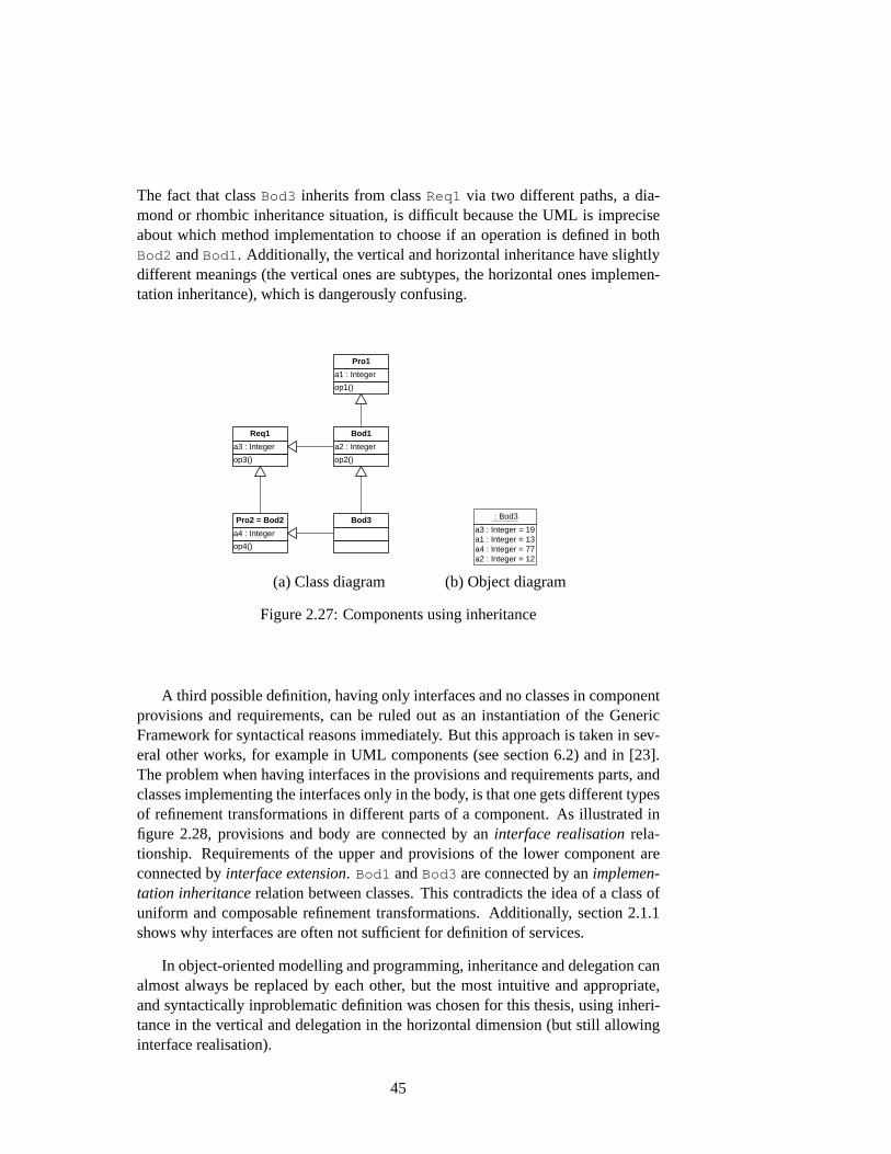
The fact that classBod3 inherits from classReq1 via two different paths, a dia-mond or rhombic inheritance situation, is difficult because the UML is impreciseabout which method implementation to choose if an operation is defined in bothBod2 andBod1. Additionally, the vertical and horizontal inheritance have slightlydifferent meanings (the vertical ones are subtypes, the horizontal ones implemen-tation inheritance), which is dangerously confusing.
op1()
a1 : Integer
Pro1
op2()
a2 : Integer
Bod1
op3()
a3 : Integer
Req1
op4()
a4 : Integer
Pro2 = Bod2 Bod3 a3 : Integer = 19 a1 : Integer = 13 a4 : Integer = 77 a2 : Integer = 12
: Bod3
(a) Class diagram (b) Object diagram
Figure 2.27:Components using inheritance
A third possible definition, having only interfaces and no classes in componentprovisions and requirements, can be ruled out as an instantiation of the GenericFramework for syntactical reasons immediately. But this approach is taken in sev-eral other works, for example in UML components (see section6.2) and in [23].The problem when having interfaces in the provisions and requirements parts, andclasses implementing the interfaces only in the body, is that one gets different typesof refinement transformations in different parts of a component. As illustrated infigure 2.28, provisions and body are connected by aninterface realisationrela-tionship. Requirements of the upper and provisions of the lower component areconnected byinterface extension. Bod1 andBod3 are connected by animplemen-tation inheritancerelation between classes. This contradicts the idea of a class ofuniform and composable refinement transformations. Additionally, section2.1.1shows why interfaces are often not sufficient for definition of services.
In object-oriented modelling and programming, inheritance and delegation canalmost always be replaced by each other, but the most intuitive and appropriate,and syntactically inproblematic definition was chosen for this thesis, using inheri-tance in the vertical and delegation in the horizontal dimension (but still allowinginterface realisation).
45
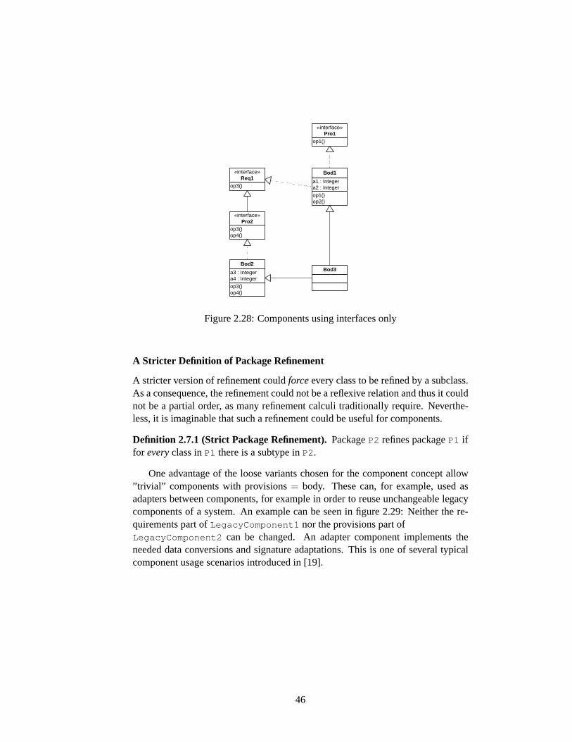
op1()
«interface» Pro1
op1() op2()
a1 : Integer a2 : Integer
Bod1
op3()
«interface» Req1
op3() op4()
«interface» Pro2
op3() op4()
a3 : Integer a4 : Integer
Bod2 Bod3
Figure 2.28:Components using interfaces only
A Stricter Definition of Package Refinement
A stricter version of refinement couldforceevery class to be refined by a subclass.As a consequence, the refinement could not be a reflexive relation and thus it couldnot be a partial order, as many refinement calculi traditionally require. Neverthe-less, it is imaginable that such a refinement could be useful for components.
Definition 2.7.1 (Strict Package Refinement).PackageP2 refines packageP1 iffor everyclass inP1 there is a subtype inP2.
One advantage of the loose variants chosen for the component concept allow”trivial” components with provisions= body. These can, for example, used asadapters between components, for example in order to reuse unchangeable legacycomponents of a system. An example can be seen in figure2.29: Neither the re-quirements part ofLegacyComponent1 nor the provisions part ofLegacyComponent2 can be changed. An adapter component implements theneeded data conversions and signature adaptations. This is one of several typicalcomponent usage scenarios introduced in [19].
46
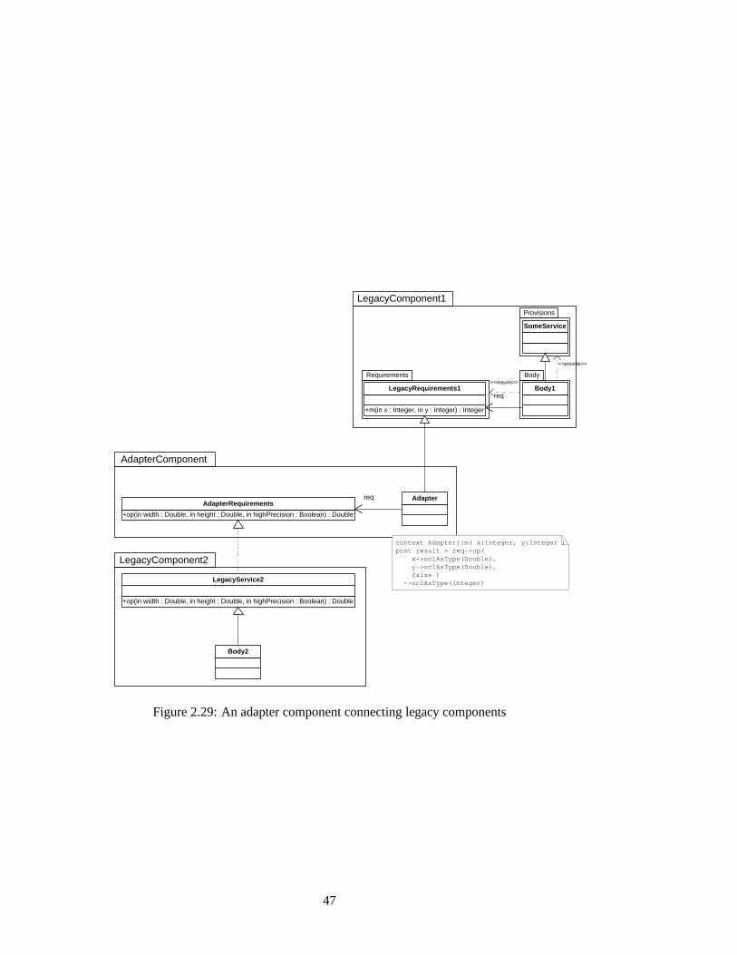
Requirements Body
Provisions
LegacyComponent2
+m(in x : Integer, in y : Integer) : Integer
LegacyRequirements1
+op(in width : Double, in height : Double, in highPrecision : Boolean) : Double
LegacyService2
AdapterComponent
Adapter
+op(in width : Double, in height : Double, in highPrecision : Boolean) : Double
AdapterRequirements req
context Adapter::m( x:Integer, y:Integer ) post result = req->op( x->oclAsType(Double), y->oclAsType(Double), false ) ->oclAsType(Integer)
Body2
SomeService
Body1
LegacyComponent1
req
<<provide>>
<<require>>
Figure 2.29:An adapter component connecting legacy components
47
Chapter 3
Instantiation of the GenericComponent Framework
3.1 Specifications, Transformations, and Inclusions
UML as a Generic Modelling Technique
The motivation for this thesis was to find out if the component concept used inthe IOSIP project can be an instantiation of the Generic Component Frameworkintroduced in [9]. There, general properties are given that a specification tech-nique should have in order to describe systems. They are given here with a shortjustification why the UML class diagram components fulfil the requirements.
• Specifications as the syntactical part:The UML syntax is formalised with a meta-model and OCL well-formednessrules. One can define a package to be aspecification.
• Behaviour or models as the semantical part:Semantics of UML class diagrams are specified in English language.
• A constraint language in order to express properties:The Object Constraint Language (OCL) fulfils the requirements of a non-formal constraint language.
• Horizontal and vertical structuring techniques:Notions of inclusion and refinement of UML packages were worked out inthe previous chapter. Their properties will be further examined now.
Package Inclusion
The additional constraints for import dependencies defined in the previous chapterjustify that a«require» dependency is an inclusion as required by the GenericFramework.
48
Definition 3.1.1 (Inclusion of Packages).PackageA includespackageB if thereis a«require» dependency fromA to B. In OCL:
let isPackageInclusion(A:Package, B:Package):Boolean =A->clientDependency->exists( r:Require |
r->supplier->includes( B ))
This inclusion relation is reflexive: It is possible that a package has a«require» dependency connected to itself, contradicting with no well-formednessrule, and having no syntactical or semantical effect.
Transitivity of this kind of inclusion is ensured by the visibility rules defined insection2.2.2, and by the ’import by reference’ as sketched on page22.
Package Refinement as a Transformation
In order to gain a component framework that reflects the desired properties, thekind of refinement transformation used is highly important. The«provide»dependency was defined with these properties in mind.
Definition 3.1.2 (Refinement and Abstraction of Packages).PackageConc isa refinementof packageAbstr if there is aprovide dependency fromConc toAbstr .
let isPackageRefinement(Conc:Package,Abstr:Package):Boolean =Conc->clientDependency->exists( p:Provide
| p->supplier->includes( Abstr ))
PackageAbstr is an abstractionof packageConc if Conc is a refinement ofAbstr .
let isPackageAbstraction(Abstr:Package,Conc:Package):Boolean =isPackageRefinement(Conc, Abstr)
According to [9] a transformation framework consists of a class of transforma-tions with the following properties:
• For each object there is an identical transformation:For each packageP1 an identical refinement is an empty packageP2 thatimports fromP1 (remember that the«provide» dependency is also animport). P1 andP2 have identical contents.
• The extension property is satisfied:As stated in the introduction, the transformations and inclusions used musthave theextension property. In the next section, it is proven for the instanti-ation defined in this thesis.
• Transformations are closed under composition:In section2.2.1it is shown how imports can be made transitive. The addi-tional property of«provide» , forbidding specialisations from the refiningto the refined package, can immediately be derived from the definition ofexistsGeneralisation .
49
Let B provideA, andC provideB.
not existsGeneralization(A, B)and not existsGeneralization(B, C)
⇒ (Definition of existsGeneralization )
not A->ownedElement->exists(ch:GeneralizableElement | B->ownedElement->exists(
par:GeneralizableElement | isSpecialisation(ch,par)))
andnot B->ownedElement->exists(
ch:GeneralizableElement | C->ownedElement->exists(par:GeneralizableElement | isSpecialisation(ch,par)
))
⇒ (A->contents is a subset ofB->contents )
not A->ownedElement->exists(ch:GeneralizableElement | C->ownedElement->exists(
par:GeneralizableElement | isSpecialisation(ch,par)))
⇒ (Definition of existsGeneralization )
not existsGeneralization(A, C)
3.2 Extension Property
The extension property expresses a ”locality assumption” in the transformationframework, meaning that transformations can applied to a larger specification ina similar way than in the smaller. In the UML instantiation chosen, this propertyis obvious and almost trivial, as there are only additive changes to models (or, interms of set theory, there are only injective mappings on the sets of model elementsowned by a package).
With packages as component parts, package inclusion using«require» ,package refinement using«provide» , and the consistency conditionisNameConflictFree , it is possible to prove our models to fulfil theextensionproperty. See figure3.1 for an example: The transformation that refinesP1 by P3
(where classA is refined by a subclassB) can equally be applied to the extendedpackageP2 (whereA is associated with another classC).
Fact 3.2.1 (Extension Property).Given packagesP1, P2, P3, a «require»dependencyr , and a«provide» dependencyp as in figure3.2, withisNameConflictFree(P2,P3 .
There is a packageP4, a «require» dependencyr’ and a«provide»dependencyp’ as in figure3.2.
50
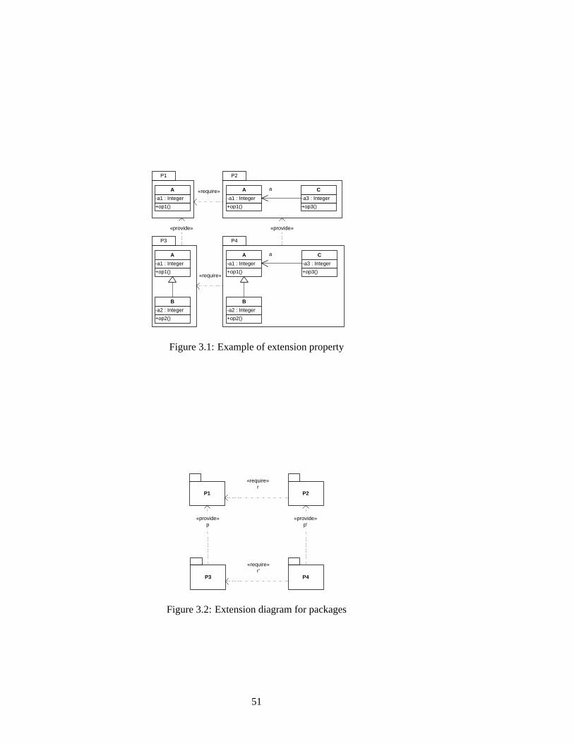
«provide» «provide»
+op1()
-a1 : Integer
A
+op2()
-a2 : Integer
B
+op3()
-a3 : Integer
C
+op1()
-a1 : Integer
A
+op1()
-a1 : Integer
A
+op2()
-a2 : Integer
B
+op3()
-a3 : Integer
C
a
a
P4
P2 P1
P3
+op1()
-a1 : Integer
A
«require»
«require»
Figure 3.1:Example of extension property
P1 P2
P3 P4
«require» r
«require» r'
«provide» p
«provide» p'
Figure 3.2:Extension diagram for packages
51
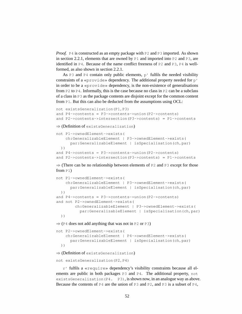
Proof. P4 is constructed as an empty package withP2 andP3 imported. As shownin section2.2.1, elements that are owned byP1 and imported intoP2 andP3, areidentified inP4. Because of the name conflict freeness ofP2 andP3, P4 is well-formed, as also shown in section2.2.1.
As P3 and P4 contain only public elements,p’ fulfils the needed visibilityconstraints of a«provide» dependency. The additional property needed forp’
in order to be a«provide» dependency, is the non-existence of generalisationsfrom P2 to P4. Informally, this is the case because no class inP2 can be a subclassof a class inP3 as the package contents are disjoint except for the common contentfrom P1. But this can also be deducted from the assumptions using OCL:
not existsGeneralization(P1,P3)and P4->contents = P3->contents->union(P2->contents)and P2->contents->intersection(P3->contents) = P1->contents
⇒ (Definition of existsGeneralization )
not P1->ownedElement->exists(ch:GeneralizableElement | P3->ownedElement->exists(
par:GeneralizableElement | isSpecialisation(ch,par)))
and P4->contents = P3->contents->union(P2->contents)and P2->contents->intersection(P3->contents) = P1->contents
⇒ (There can be no relationship between elements ofP2 andP3 except for thosefrom P1)
not P1->ownedElement->exists(ch:GeneralizableElement | P3->ownedElement->exists(
par:GeneralizableElement | isSpecialisation(ch,par)))
and P4->contents = P3->contents->union(P2->contents)and not P2->ownedElement->exists(
ch:GeneralizableElement | P3->ownedElement->exists(par:GeneralizableElement | isSpecialisation(ch,par)
))
⇒ (P4 does not add anything that was not inP2 or P3)
not P2->ownedElement->exists(ch:GeneralizableElement | P4->ownedElement->exists(
par:GeneralizableElement | isSpecialisation(ch,par)))
⇒ (Definition of existsGeneralization )
not existsGeneralization(P2,P4)
r’ fulfils a «require» dependency’s visibility constraints because all el-ements are public in both packagesP3 and P4. The additional property,not
existsGeneralization(P4. P3) , is shown now, in an analogue way as above.Because the contents ofP4 are the union ofP3 andP2, andP3 is a subset ofP4,
52
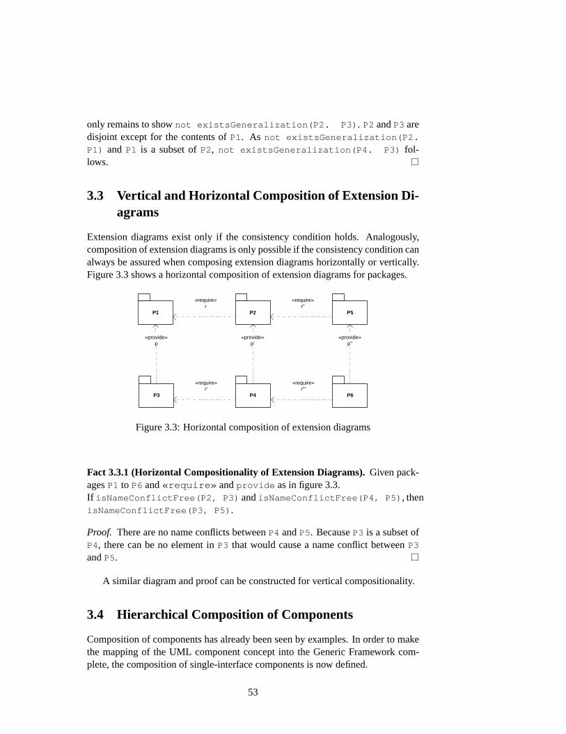
only remains to shownot existsGeneralization(P2. P3) . P2 andP3 aredisjoint except for the contents ofP1. As not existsGeneralization(P2.
P1) and P1 is a subset ofP2, not existsGeneralization(P4. P3) fol-lows.
3.3 Vertical and Horizontal Composition of Extension Di-agrams
Extension diagrams exist only if the consistency condition holds. Analogously,composition of extension diagrams is only possible if the consistency condition canalways be assured when composing extension diagrams horizontally or vertically.Figure3.3shows a horizontal composition of extension diagrams for packages.
P1 P2
P3 P4
«require» r
«require» r'
«provide» p
«provide» p'
P5
P6
«require» r''
«require» r'''
«provide» p''
Figure 3.3:Horizontal composition of extension diagrams
Fact 3.3.1 (Horizontal Compositionality of Extension Diagrams).Given pack-agesP1 to P6 and«require» andprovide as in figure3.3.If isNameConflictFree(P2, P3) andisNameConflictFree(P4, P5) , thenisNameConflictFree(P3, P5) .
Proof. There are no name conflicts betweenP4 andP5. BecauseP3 is a subset ofP4, there can be no element inP3 that would cause a name conflict betweenP3
andP5.
A similar diagram and proof can be constructed for vertical compositionality.
3.4 Hierarchical Composition of Components
Composition of components has already been seen by examples. In order to makethe mapping of the UML component concept into the Generic Framework com-plete, the composition of single-interface components is now defined.
53

Definition 3.4.1 (Single-Interface Component).A component is calledsingle-interface componentif it contains exactly one provisions package and exactly onerequirements package. In OCL:
context Component def:let isSingleInterface():Boolean =
self->ownedElement->select(p:Package| p.oclIsKindOf(Provisions))->size() = 1
andself->ownedElement->select(p:Package
| p.oclIsKindOf(Requirements))->size() = 1
Definition 3.4.2 (Connector). A connector between single-interface componentsC1 andC2 is a «provide» refinement between one component’s requirementsand the other’s provisions package.
Definition 3.4.3 (Hierarchical Composition). The hierarchical compositionofsingle-interface componentsC1 andC2 via a connectorconn (see figure3.4) isa single-interface componentC3 with the provisions ofC1 as its provisions part,the requirements ofC2 as its requirements part, and a packageBod3 as its bodypart. PackageBod3 as well as a«provide» dependency and a«require»are implicitly given by the extension property as shown in section3.2, and bytransitivity of refinements and inclusions.
According to the Generic Framework, hierarchical composition of single-inter-face components is possible if the component modelling technique has the exten-sion property. This has been proven in section3.2. The main practical effect of thegeneric compositionality results for the UML components defined here is that con-sistency has only to be checkedlocally when composing arbitrarily large systemshierarchically.
A different kind of composition calledstructured compositioncould also havebeen defined by requiring that both of the existing components and the connectorform the new component’s body, see figure3.5. The flattened composition is morecompact in notation, where the second preserves the underlying structure. Alsonote that the new provided and required interface packages could have been givenalias names by the«require» and«provide» dependencies.
A larger and more detailed example of composition of components is shownin figures5.16and5.17(pages92and93, respectively). There, multiple interfacesexist, and they are given alias names when composing.
3.5 Multi-Interface Components and Partial Composition
In many situations is is useful to define components which require services frommore than one component, and which offer services to more than one component.This leads to a definition of components that have multiple provisions and require-ments interfaces. The components as defined in2.4are such multi-interface com-ponents.
54

«provisions» Pro1
«requirements» Req1
«provisions» Pro2
«requirements» Req2
«provide» conn
«body» Bod1
«provide» pro1
«body» Bod2
«provide» pro2
«require» req1
«require» req2
«require» req1'
«provide» xconn
«body» Bod3
induced by extension property
«provide»
«require»
Figure 3.4:Composition of components
55

«component» Bod3
«component» Comp3
«component» Comp2
«component» Comp1
«provisions» Pro1
«requirements» Req1
«provisions» Pro2
«requirements» Req2
«provide» conn
«body» Bod1
«provide» pro1
«body» Bod2
«provide» pro2
«require» req1
«require» req2
«require» req1'
«provide» xconn
«body» InducedBod3
induced by extension property
«provisions» Pro1
«requirements» Req2
«provide»
«require»
Figure 3.5:Structured composition of components
56
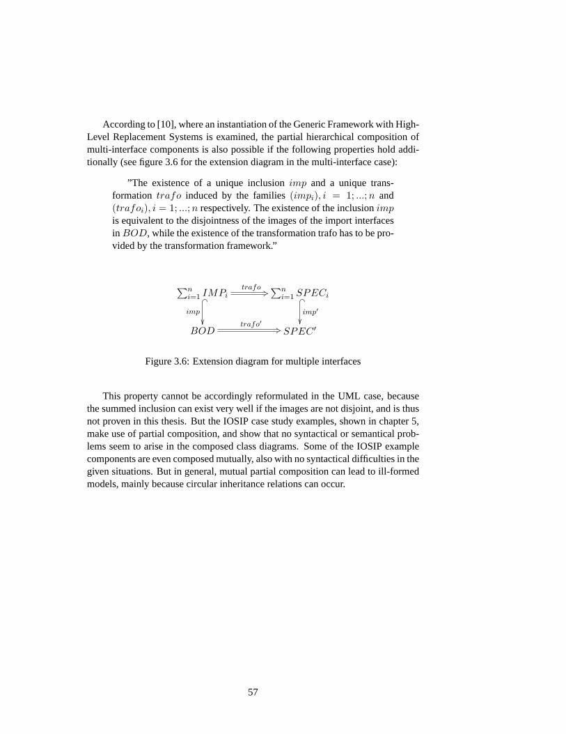
According to [10], where an instantiation of the Generic Framework with High-Level Replacement Systems is examined, the partial hierarchical composition ofmulti-interface components is also possible if the following properties hold addi-tionally (see figure3.6for the extension diagram in the multi-interface case):
”The existence of a unique inclusionimp and a unique trans-formation trafo induced by the families(impi), i = 1; ...;n and(trafoi), i = 1; ...; n respectively. The existence of the inclusionimpis equivalent to the disjointness of the images of the import interfacesin BOD, while the existence of the transformation trafo has to be pro-vided by the transformation framework.”
∑ni=1 IMPi
trafo +3� _
imp
²²
∑ni=1 SPECi� _
imp′
²²BOD
trafo′ +3 SPEC ′
Figure 3.6:Extension diagram for multiple interfaces
This property cannot be accordingly reformulated in the UML case, becausethe summed inclusion can exist very well if the images are not disjoint, and is thusnot proven in this thesis. But the IOSIP case study examples, shown in chapter5,make use of partial composition, and show that no syntactical or semantical prob-lems seem to arise in the composed class diagrams. Some of the IOSIP examplecomponents are even composed mutually, also with no syntactical difficulties in thegiven situations. But in general, mutual partial composition can lead to ill-formedmodels, mainly because circular inheritance relations can occur.
57
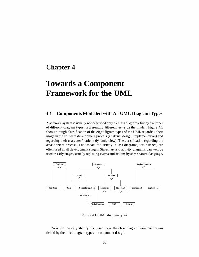
Chapter 4
Towards a ComponentFramework for the UML
4.1 Components Modelled with All UML Diagram Types
A software system is usually not described only by class diagrams, but by a numberof different diagram types, representing differentviewson the model. Figure4.1shows a rough classification of the eight digram types of the UML regarding theirusage in the software development process (analysis, design, implementation) andregarding their character (static or dynamic view). The classification regarding thedevelopment process is not meant too strictly. Class diagrams, for instance, areoften used in all development stages. Statechart and activity diagrams can well beused in early stages, usually replacing events and actions by some natural language.
Static
Class Use Case Object (Snapshot)
Dynamic
Interaction
Collaboration Activity
Statechart Component Deployment
Implementation Analysis Design
special case of
MSC
Figure 4.1:UML diagram types
Now will be very shortly discussed, how the class diagram view can be en-riched by the other diagram types in component design.
58
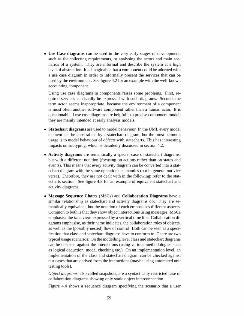
• Use Case diagramscan be used in the very early stages of development,such as for collecting requirements, or analysing the actors and main sce-narios of a system. They are informal and describe the system at a highlevel of abstraction. It is imaginable that a component could be adorned witha use case diagram in order to informally present the services that can beused by the environment. See figure4.2for an example with the well-knownaccounting component.
Using use case diagrams in components raises some problems. First, re-quired services can hardly be expressed with such diagrams. Second, theterm actor seems inappropriate, because the environment of a componentis most often another software component rather than a human actor. It isquestionable if use case diagrams are helpful in a precise component model;they are mainly intended at early analysis models.
• Statechart diagramsare used to model behaviour. In the UML every modelelement can be constrained by a statechart diagram, but the most commonusage is to model behaviour ofobjectswith statecharts. This has interestingimpacts on subtyping, which is detailedly discussed in section4.2.
• Activity diagrams are semantically a special case of statechart diagrams,but with a different notation (focusing on actions rather than on states andevents). This means that every activity diagram can be converted into a stat-echart diagram with the same operational semantics (but in general not viceversa). Therefore, they are not dealt with in the following; refer to the stat-echarts section. See figure4.3 for an example of equivalent statechart andactivity diagrams.
• Message Sequence Charts(MSCs) andCollaboration Diagrams have asimilar relationship as statechart and activity diagrams do: They are se-mantically equivalent, but the notation of each emphasises different aspects.Common to both is that they show object interactions using messages. MSCsemphasise thetimeview, expressed by a vertical time line. Collaboration di-agrams emphasise, as their name indicates, the collaboration roles of objects,as well as the (possibly nested) flow of control. Both can be seen as a speci-fication that class and statechart diagrams have to conform to. There are twotypical usage scenarios: On the modelling level class and statechart diagramscan be checked against the interactions (using various methodologies suchas logical deduction, model checking etc.). On an implementation level, animplementation of the class and statechart diagram can be checked againsttest cases that are derived from the interactions (maybe using automated unittesting tools).
Object diagrams, also called snapshots, are a syntactically restricted case ofcollaboration diagrams showing only static object interconnection.
Figure 4.4 shows a sequence diagram specifying the scenario that a user
59

withdraws exactly the amount of the current balance of an account, i.e. thathe empties the account. The class and statechart diagrams of the classesinvolved must ensure that this scenario can occur in order to make the wholemodel consistent.
Components as defined in this thesis can be attached with such interactiondiagrams in each part. In contrast to statechart diagrams, a refinement rela-tion between interaction diagrams is not as important, but each componentpart must be consistent between class, statechart and interaction diagrams.
• Component and deployment diagrams are useful for system assembly,which nowadays is a role clearly distinct from component development.They emphasise physical and implementation aspects. Component diagramsdefine component types and their static interconnection, deployment dia-grams show component instances, their links, and possibly their distributionon computers. The components defined in this thesis are more abstract; com-ponent diagrams may be an appropriate technique when coming close to animplementation. They are discussed further in section6.2.
Accounting Component
deposit money
withdraw money
client withdraw money
from cheque account
Figure 4.2:A use case diagram for the accounting component
4.2 Behavioural Specification and Refinement
The most commonly used technique for modelling behaviour of objects are state-chart diagrams. As per [28, sect. 2.12.1] they can be used to model the behaviourof any kind of model element. In the following, only objects – instances of classes– are modelled by statechart diagrams.
In the component framework presented in this thesis a refinement concept forclasses was introduced that regards OCL specifications as semantical constraints.Another refinement concept is needed when behaviour of classes is specified withstatecharts. As sketched in figure4.5, there should be a well-defined relation be-tween the statecharts specifying a superclass and a subclass. Constraints on thisrelation are developed in this section.
60
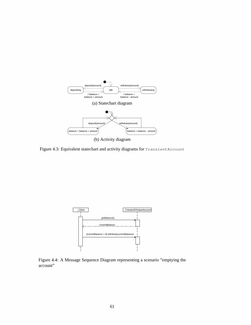
idle withdrawing depositing
withdraw(amount)
/ balance = balance + amount
deposit(amount)
/ balance = balance - amount
(a) Statechart diagram
balance = balance + amount balance = balance - amount
deposit(amount) withdraw(amount)
(b) Activity diagram
Figure 4.3:Equivalent statechart and activity diagrams forTransientAccount
: TransientChequeAccount : Client
getBalance()
currentBalance
[currentBalance > 0] withdraw(currentBalance)
Figure 4.4:A Message Sequence Diagram representing a scenario ”emptying theaccount”
61
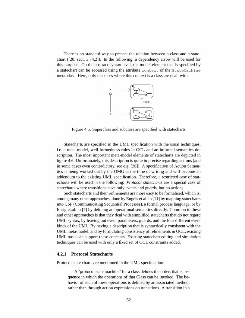
There is no standard way to present the relation between a class and a state-chart ([28, sect. 3.74.2]). In the following, a dependency arrow will be used forthis purpose. On the abstract syntax level, the model element that is specified bya statechart can be accessed using the attributecontext of the StateMachine
meta-class. Here, only the cases where this context is a class are dealt with.
A
B
«refine»
Figure 4.5:Superclass and subclass are specified with statecharts
Statecharts are specified in the UML specification with the usual techniques,i.e. a meta-model, well-formedness rules in OCL and an informal semantics de-scription. The most important meta-model elements of statecharts are depicted infigure4.6. Unfortunately, this description is quite imprecise regarding actions (andin some cases even contradictory, see e.g. [26]). A specification of Action Seman-tics is being worked out by the OMG at the time of writing and will become anaddendum to the existing UML specification. Therefore, a restricted case of stat-echarts will be used in the following:Protocol statechartsare a special case ofstatecharts where transitions have only events and guards, but no actions.
Such statecharts and their refinements are more easy to be formalised, which is,among many other approaches, done by Engels et.al. in [11] by mapping statechartsinto CSP (Communicating Sequential Processes), a formal process language, or byEhrig et.al. in [7] by defining an operational semantics directly. Common to theseand other approaches is that they deal with simplified statecharts that do not regardUML syntax, by leaving out event parameters, guards, and the four different eventkinds of the UML. By having a description that is syntactically consistent with theUML meta-model, and by formulating consistency of refinements in OCL, existingUML tools can support these concepts. Existing statechart editing and simulationtechniques can be used with only a fixed set of OCL constraints added.
4.2.1 Protocol Statecharts
Protocol state charts are mentioned in the UML specification:
A ’protocol state machine’ for a class defines the order; that is, se-quence in which the operations of that Class can be invoked. The be-havior of each of these operations is defined by an associated method,rather than through action expressions on transitions. A transition in a
62
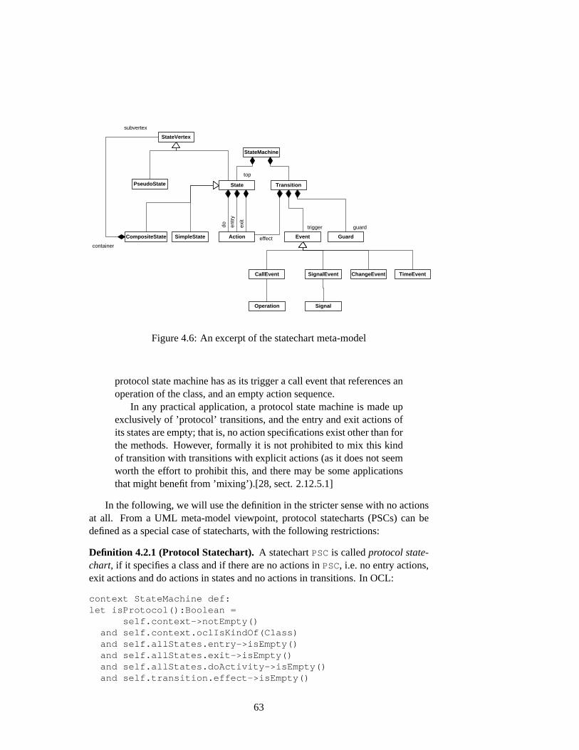
StateMachine
State Transition
Event Guard Action
do
entr
y
exit
effect
top
trigger guard
CallEvent SignalEvent ChangeEvent TimeEvent
Operation Signal
StateVertex
SimpleState CompositeState
PseudoState
container
subvertex
Figure 4.6:An excerpt of the statechart meta-model
protocol state machine has as its trigger a call event that references anoperation of the class, and an empty action sequence.
In any practical application, a protocol state machine is made upexclusively of ’protocol’ transitions, and the entry and exit actions ofits states are empty; that is, no action specifications exist other than forthe methods. However, formally it is not prohibited to mix this kindof transition with transitions with explicit actions (as it does not seemworth the effort to prohibit this, and there may be some applicationsthat might benefit from ’mixing’).[28, sect. 2.12.5.1]
In the following, we will use the definition in the stricter sense with no actionsat all. From a UML meta-model viewpoint, protocol statecharts (PSCs) can bedefined as a special case of statecharts, with the following restrictions:
Definition 4.2.1 (Protocol Statechart).A statechartPSCis calledprotocol state-chart, if it specifies a class and if there are no actions inPSC, i.e. no entry actions,exit actions and do actions in states and no actions in transitions. In OCL:
context StateMachine def:let isProtocol():Boolean =
self.context->notEmpty()and self.context.oclIsKindOf(Class)and self.allStates.entry->isEmpty()and self.allStates.exit->isEmpty()and self.allStates.doActivity->isEmpty()and self.transition.effect->isEmpty()
63

There are four kinds of events defined in the UML [28, section 2.12.2] that canbe used as transition labels: Events resulting from asynchronous method callmapto a CallEvent , asynchronous signal eventsmap to aSignalEvent , timeoutevents map to aTimeEvent , and events that indicate achange of some booleanexpressionmap to aChangeEvent . The first two event kinds have to be consistentwith the specified classes by requiring a corresponding operation or signal recep-tion, respectively; time events of the formafter (x) are always well-formed aslong asx expresses a time (such asafter(5 sec) ); change events can containany expression resulting in atrue or false value.
Any query operations are typically not interesting for a protocol: Queries donot cause any state changes, and they may be called always (except, of course, iftheir OCL precondition is not fulfilled. Usually queries have no preconditions).Furthermore, signal receptions cannot be queries ([28, section 2.9.3.17]).
As most of the other UML diagrams, statecharts can be used at different levelsof precision. Transition labels can in practice contain event signatures that arenot defined in the corresponding class, or even natural text. As this thesis aimsat syntactically precise modelling, we only regard statecharts that are syntacticallycorrect with respect to the class they specify.
Definition 4.2.2 (Syntactically Correct Protocol Statechart).A statechart is asyntactically correct protocol statechartif it is a protocol, there are only call eventsin the statechart transitions for which there is a corresponding operation defined inthe class, and there are only signal events for which there is a corresponding signalreception defined in the class. In OCL:
context StateMachine def:let isSyntacticallyCorrect():Boolean =
isProtocol()and
self.transitions.trigger->forAll( call:CallEvent |self.context.feature->exists( op:Operation |
op = call->operation ) )and self.transitions.trigger->forAll( sig:SignalEvent |
self.context.feature->exists( rec:SignalReception |rec->signal = sig->signal ) )
Note that ill-formed expressions in time events or change events are already’ruled out’ by the UML well-formedness rules.
Invokable and Observable Behaviour
Engels et al. distinguish carefully in [6] between state machines representing theinvokableandobservablebehaviour of objects. The invokable perspective statesthat an object of the superclass can always be replaced by an object of the subclasswithout any change in behaviour. The observable one states that every trace ofevents possible for an object of the subclass must also be possible for an object ofthe superclass. The following definitions are adapted from [6]:
64
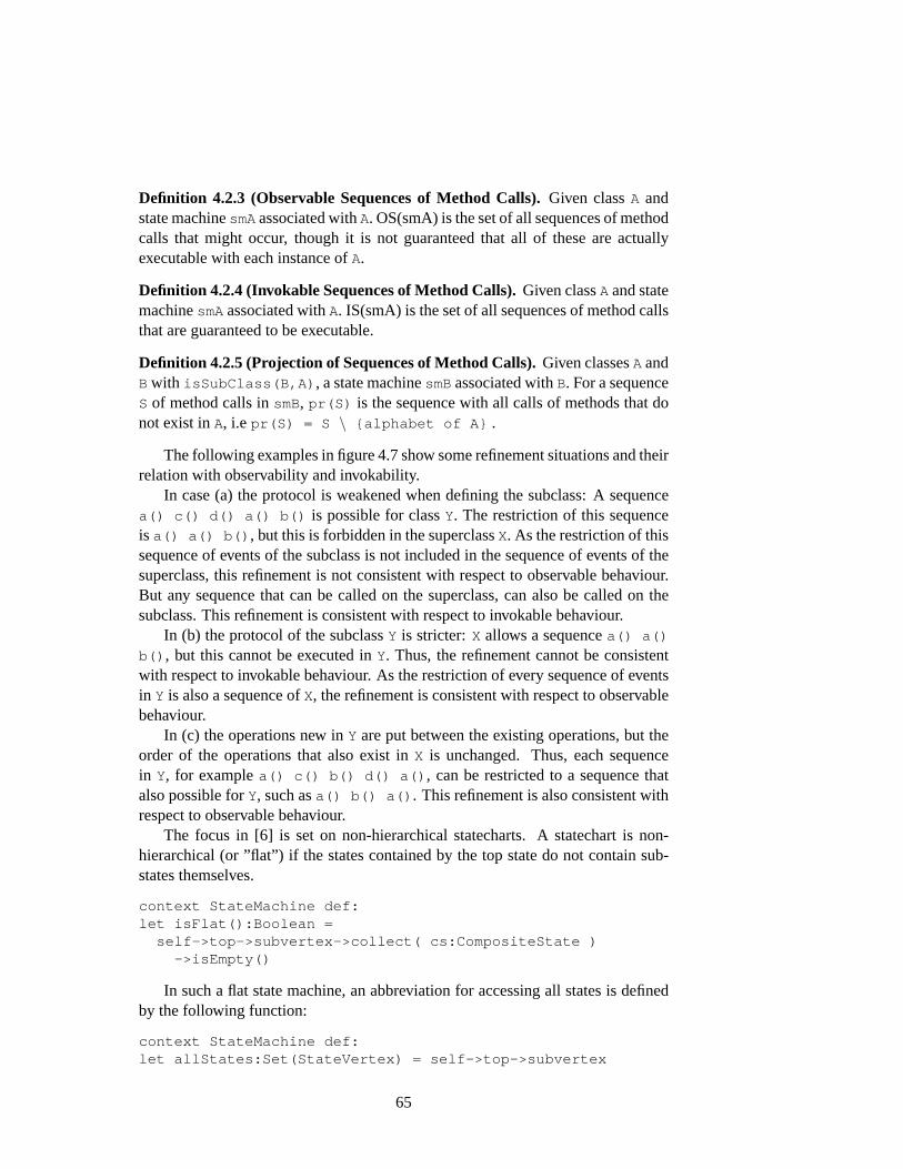
Definition 4.2.3 (Observable Sequences of Method Calls).Given classA andstate machinesmAassociated withA. OS(smA) is the set of all sequences of methodcalls that might occur, though it is not guaranteed that all of these are actuallyexecutable with each instance ofA.
Definition 4.2.4 (Invokable Sequences of Method Calls).Given classA and statemachinesmAassociated withA. IS(smA) is the set of all sequences of method callsthat are guaranteed to be executable.
Definition 4.2.5 (Projection of Sequences of Method Calls).Given classesA andB with isSubClass(B,A) , a state machinesmBassociated withB. For a sequenceS of method calls insmB, pr(S) is the sequence with all calls of methods that donot exist inA, i.e pr(S) = S \ {alphabet of A} .
The following examples in figure4.7show some refinement situations and theirrelation with observability and invokability.
In case (a) the protocol is weakened when defining the subclass: A sequencea() c() d() a() b() is possible for classY. The restriction of this sequenceis a() a() b() , but this is forbidden in the superclassX. As the restriction of thissequence of events of the subclass is not included in the sequence of events of thesuperclass, this refinement is not consistent with respect to observable behaviour.But any sequence that can be called on the superclass, can also be called on thesubclass. This refinement is consistent with respect to invokable behaviour.
In (b) the protocol of the subclassY is stricter:X allows a sequencea() a()
b() , but this cannot be executed inY. Thus, the refinement cannot be consistentwith respect to invokable behaviour. As the restriction of every sequence of eventsin Y is also a sequence ofX, the refinement is consistent with respect to observablebehaviour.
In (c) the operations new inY are put between the existing operations, but theorder of the operations that also exist inX is unchanged. Thus, each sequencein Y, for examplea() c() b() d() a() , can be restricted to a sequence thatalso possible forY, such asa() b() a() . This refinement is also consistent withrespect to observable behaviour.
The focus in [6] is set on non-hierarchical statecharts. A statechart is non-hierarchical (or ”flat”) if the states contained by the top state do not contain sub-states themselves.
context StateMachine def:let isFlat():Boolean =
self->top->subvertex->collect( cs:CompositeState )->isEmpty()
In such a flat state machine, an abbreviation for accessing all states is definedby the following function:
context StateMachine def:let allStates:Set(StateVertex) = self->top->subvertex
65
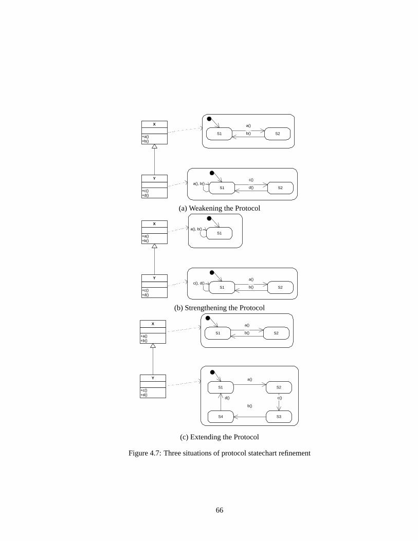
+a() +b()
X
+c() +d()
Y
S1 S2
a()
b()
a(), b() S1 S2
c()
d()
(a) Weakening the Protocol
+a() +b()
X
+c() +d()
Y
S1
c(), d() S1 S2
a()
b()
a(), b()
(b) Strengthening the Protocol
+a() +b()
X
+c() +d()
Y
S1 S2
a()
b()
S1 S2
a()
c()
S3 S4
b()
d()
(c) Extending the Protocol
Figure 4.7:Three situations of protocol statechart refinement
66
As there is exactly one initial state, the following function can be used to iden-tify the initial state:
context StateMachine def:let initialState:PseudoState =
allStates->select(ps:PseudoState |ps.kind = #initial)->asSequence()->first()
The definitions in this section are based on [6]. Here, a definition of statechartsis given that is notationally close to the one given in Z notation in [6].
Definition 4.2.6 (Protocol Statechart).Let fd(C) = (nameC , attrsC , opnsC) aclass’s full descriptor,States be a set of object states, andLabels = opnsC ∪{τ}the set of transition labels, consisting of operation names and the empty transitionlabel. A statechartis a labelled transition system(States, Labels, δ, S0), whereδ : States × Labels × States is the transition relation andS0 ∈ States is theinitial state.
The relation to the definition above should be obvious: While this is a con-structive, set-theoretical definition (from the bottom), the definition above restrictsthe existing UML statechart definition to a special class (from the top). It is hardto prove the equivalence because of the very different formalisms; the intuitionshould suffice here.
4.2.2 Protocol Statechart Refinement
In [6] refinement of statecharts is expressed in terms of statechart homomorphismsthat preserve the behaviour in the desired way. The homomorphism properties areformulated as follows (again slightly modifying the original notation):
Definition 4.2.7 (Statechart Homomorphism).LetPSCA = (StatesA, LabelsA,δA, SA
0 ) andPSCB = (StatesB, LabelsB, δB, SB0 ) be protocol statecharts. A
functionh : StatesA → StatesB is astatechart homomorphismif h(SA0 ) = SB
0
and for each transitionsop() // t ∈ δA:
h(s) = h(t)
or in δB exists a transitionh(s)op() // h(t)
or in δB exists a transitionh(s) τ // h(t)
This definition implies that the initial state is preserved, and that a label on atransition can be mapped either to a corresponding transition, to an empty transi-tion, or to identified states (which might be interpreted as an empty transition on asingle state). See figure4.8for the three situations.
An equivalent formulation that uses the UML notation is given now. It regardsthe fact that call events and signal events may be used. It restricts the statechartsto have a the same event kind in both statecharts for a corresponding transitions.
67
op()
op()
h h
op()
h h
t
op()
h h
Figure 4.8:Mappings allowed in a statechart homomorphism
Relaxing this condition could lead to unexpected changes of concurrent behaviourof the specified objects. An additional functioneventsMatch is defined for thispurpose. Remember that only syntactically correct statecharts, i.e. those with op-erations and receptions defined in the corresponding class, are regarded.
Definition 4.2.8 (Statechart Homomorphism). Let PSCA and PSCB be state-charts. A functionh(state:StateVertex):StateVertex is astatechart ho-momorphismbetweenPSCAandPSCBif
h(PSCA->initialState) = PSCB->initialStateandPSCA->transition->forAll(tra:Transition |
h(tra->source) = h(tra->target)orPSCB->transition->exists(trb:Transition |
trb->source = h(tra->source)and trb->target = h(tra->target)and eventsMatch(tra->trigger, trb->trigger)
)orPSCB->transition->exists(trb:Transition |
trb->source = h(tra->source)and trb->target = h(tra->target)and trb->trigger->isEmpty()
))
The definition uses on operationeventsMatch that checks for syntactical co-herence of the events on the transitions of the two statecharts:
let eventsMatch(ev1:Event, ev2:Event):Boolean =ev1->oclIsKindOf(CallEvent) implies
( ev2->oclIsKindOf(CallEvent) andev1.oclAsKind(CallEvent)->operation =
ev2.oclAsKind(CallEvent)->operation)
andev1->oclIsKindOf(SignalEvent) implies
( ev2->oclIsKindOf(SignalEvent) and
68

ev1.oclAsKind(SignalEvent)->signal =ev2.oclAsKind(SignalEvent)->signal
)
If event signatures with parameters are to be regarded, rather than only thenames of the operations, the definition ofeventsMatch could have been strictenedby the additional condition that the parameter list must be identical. This is redun-dant, though: On the abstract syntax level the operations respectively signals existonly once, there cannot be two distinct operations with the same signature in oneclass. See figure4.9 for an example of two transitions, possibly occurring in twodifferent statecharts, but referring to one operation.
op(x:Integer)
op(x:Integer) [x>0]
t1 : Transition
t2 : Transition
ev1 : CallEvent
ev2 : CallEvent
op : Operation
x : Parameter
g : Guard
(a) Concrete notation (b) Abstract syntax
Figure 4.9:Two transitions
If, additionally, transition guards are to be regarded in statechart homomor-phisms, there are several possibilities for a definition. We could force the guardexpressions to be identical in both transitions, leading to the following extensionof the second case of the homomorphism definition:
PSCB->transition->exists(trb:Transition |trb->source = h(tra->source)and trb->target = h(tra->target)and eventsMatch(tra->trigger, trb->trigger)and trb->guard->expression = tra->guard->expression
)
We could also allow that the guard of the subclass’s transition is stronger thanthe guard of the superclass’s one. Similarly, we could allow that the second one isa syntactical restriction of the first one, because the guard of the subclass could bean expression over a larger set of attributes than the guard of the superclass.
Using the definition of a statechart homomorphism and of observable and in-vokable behaviour, behaviourally consistent refinement of statecharts can now bedefined:
Definition 4.2.9 (Behavioural Consistency of Subclasses).Let A, B classes withisSubclass(B,A) , andPSCAandPSCBprotocol statecharts constrainingA andB, respectively.PSCAandPSCBarebehaviourally consistent with respect to ob-servable behaviour, if there is a homomorphism
69

h : States(PSCB) → States(PSCA) as defined above.PSCAandPSCBarebehaviourally consistent with respect to invokable behaviour, if there is a homo-morphismh : States(PSCA) → States(PSCB) as defined above.
In the notation of Ebert et.al.PSCBrefinesPSCAif
• PSCAandPSCBrepresent observable behaviourandpr(OS(PSCB)) ⊆ OS(PSCA)
or
• PSCAandPSCBrepresent invokable behaviourandIS(PSCA)) ⊆ IS(PSCB) .
A refinement cannot be defined (and makes no sense) ifPSCArepresents observableandPSCBinvokable behaviour or vice versa.
Introducing Hierarchy
Figure4.10shows that the observability approach is most intuitive when refing astatechart by adding sub-statecharts to states, using the hierarchy mechanism ofstatecharts. A excerpt of a protocol statechart, defining thatb() can be called aftera() was called, can be extended by specifying that an additional operation,c() ,has to be called in between. Using the hierarchical notation, the notational hidingexactly matches the hiding of events in the trace.
a() b()
(a) The superclass’s statecharta() c() b()
(b) The subclass’s statechart
c() a() b()
(c) Equivalent notation for (b), using hierarchya() b()
(d) Hiding the details
Figure 4.10:Refining an excerpt of a statechart, preserving observable traces
70
The IOSIP case study contains several examples of this kind of relation be-tween superclass and subclass. An example is the refinement of classNegotiator
by classNegotiatorBod , see figures5.4to 5.7starting at page81.
Refinement of statecharts by introducingparallel substates is not handled inthis thesis. There are no parallel statecharts at all in the IOSIP case study, anda parallel statechart does not reflect the intuition that a statechart specifies one(single-threaded) object’s behaviour. There exists concurrency in the IOSIP exam-ples, but it is expressed by concurrent execution of different object’s statecharts.An example is the concurrent execution ofInterpreter andNegotiator ob-jects, where synchronisation is guaranteed by asynchronous signal emission andreception. See section5.3.1for examples. Parallel extension, though, is handled in[6] and should be easily mapped to the notations used in this thesis.
4.3 Components in the Context of Software DevelopmentProcesses
An additional goal of a component concept not stated before is that componentsshould be able to be used in different phases of asoftware development process.
The UML is also intended to be used throughout the development process, butit does not define such a process.1 The different diagram types can be used indifferent phases, and refined in a phase transition. Similarly, the UML componentconcept introduced in this thesis shall make possible suitable refinement conceptsfor components. This section sketches such approaches, but does neither show howany of the proposed techniques would be defined, nor prove that they are applicablewith the methods defined so far.
Refining UML models, thus getting closer to an implementation, is not trivial;many decisions are to be made. The key task is, of course, finding efficient algo-rithms for realising the (non-constructively) specified functionality. Programminglanguage-specific questions include data types (is an OCLInteger mapped toJava typebyte , short , int , long , java.math.BigInteger , with 8-bit, 16-bit, 32-bit, 64-bit and arbitrary precision, respectively), naming conventions, orstructural mismatches with the UML model (e.g. in Java there is no multiple inher-itance, but realisation of multiple interfaces is allowed. All of the following ideasdo not have such depth but are rather conceptual.
The following definitions are closely related to those in [8, chapter 5] and wereadapted to the terminology used in the Generic Component Framework and in thisthesis.
1There has been some confusion about this fact in the past because early versions (before 1996)of the Unified Modelling Language (UML) were titledUnified Method(UM).
71
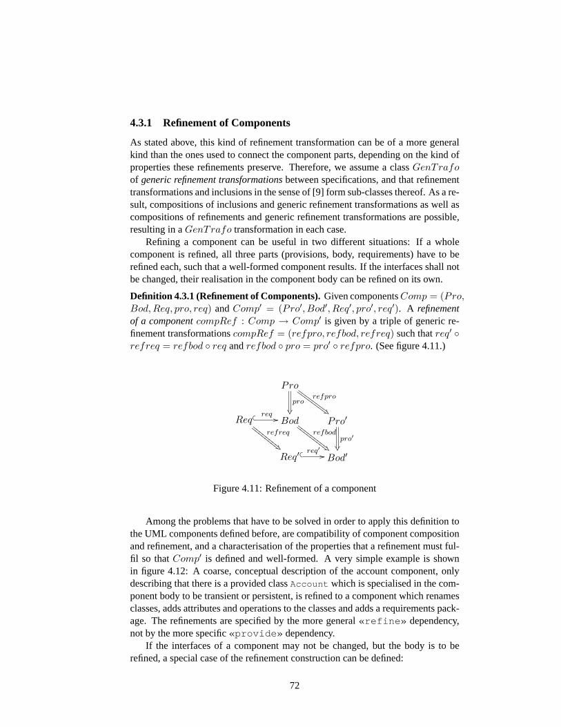
4.3.1 Refinement of Components
As stated above, this kind of refinement transformation can be of a more generalkind than the ones used to connect the component parts, depending on the kind ofproperties these refinements preserve. Therefore, we assume a classGenTrafoof generic refinement transformationsbetween specifications, and that refinementtransformations and inclusions in the sense of [9] form sub-classes thereof. As a re-sult, compositions of inclusions and generic refinement transformations as well ascompositions of refinements and generic refinement transformations are possible,resulting in aGenTrafo transformation in each case.
Refining a component can be useful in two different situations: If a wholecomponent is refined, all three parts (provisions, body, requirements) have to berefined each, such that a well-formed component results. If the interfaces shall notbe changed, their realisation in the component body can be refined on its own.
Definition 4.3.1 (Refinement of Components).Given componentsComp = (Pro,Bod,Req, pro, req) andComp′ = (Pro′, Bod′, Req′, pro′, req′). A refinementof a componentcompRef : Comp → Comp′ is given by a triple of generic re-finement transformationscompRef = (refpro, refbod, refreq) such thatreq′ ◦refreq = refbod ◦ req andrefbod ◦ pro = pro′ ◦ refpro. (See figure4.11.)
Pro
pro
®
refpro
Â'GGGGGGGG
GGGGGGGG
Reqrefreq
Á&EE
EEEE
EE
EEEE
EEEE
� � req // Bodrefbod
Â'FFFF
FFFF
F
FFFF
FFFF
F Pro′
pro′
®¶Req′ �
� req′ // Bod′
Figure 4.11:Refinement of a component
Among the problems that have to be solved in order to apply this definition tothe UML components defined before, are compatibility of component compositionand refinement, and a characterisation of the properties that a refinement must ful-fil so thatComp′ is defined and well-formed. A very simple example is shownin figure 4.12: A coarse, conceptual description of the account component, onlydescribing that there is a provided classAccount which is specialised in the com-ponent body to be transient or persistent, is refined to a component which renamesclasses, adds attributes and operations to the classes and adds a requirements pack-age. The refinements are specified by the more general«refine» dependency,not by the more specific«provide» dependency.
If the interfaces of a component may not be changed, but the body is to berefined, a special case of the refinement construction can be defined:
72

«body» Bod
TransAcc PersAcc
«component» Accounts (Analysis)
«provide»
«provide»
«provisions» Accounts
«body» AccountsImplementation
«provisions» Pro
«requirements» Persistency
«require»
+deposit(in amount : Integer) +withdraw(in amount : Integer)
Account
-number : Integer
PersistentAccount
«query» +getNumber() : Integer «query» +getBalance() : Integer +deposit(in amount : Integer) +withdraw(in amount : Integer)
Account
-number : Integer -balance : Integer
TransientAccount
+getBalance(in number : Integer) : Integer +setBalance(in number : Integer, in bal : Integer)
DBInterface
db
«refine»
«requirements» (empty)
«require»
«refine»
«component» Accounts
Figure 4.12:Example for refinement of a component
73
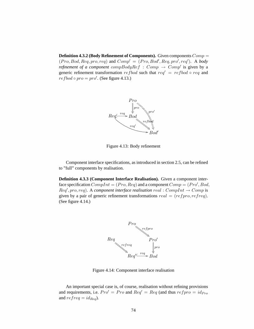
Definition 4.3.2 (Body Refinement of Components).Given componentsComp =(Pro, Bod, Req, pro, req) andComp′ = (Pro, Bod′, Req, pro′, req′). A bodyrefinement of a componentcompBodyRef : Comp → Comp′ is given by ageneric refinement transformationrefbod such thatreq′ = refbod ◦ req andrefbod ◦ pro = pro′. (See figure4.13.)
Pro
pro
®¶ pro′
±¹
Req� p
req′
..
� � req // Bodrefbod
Â'GGGGGGGG
GGGGGGGG
Bod′
Figure 4.13:Body refinement
Component interface specifications, as introduced in section2.5, can be refinedto ”full” components by realisation.
Definition 4.3.3 (Component Interface Realisation).Given a component inter-face specificationCompInt = (Pro, Req) and a componentComp = (Pro′, Bod,Req′, pro, req). A component interface realisationreal : CompInt → Comp isgiven by a pair of generic refinement transformationsreal = (refpro, refreq).(See figure4.14.)
Prorefpro
Â'GGGGGGGG
GGGGGGGG
Reqrefreq
Á&EE
EEEE
EE
EEEE
EEEE
Pro′
pro
®¶Req′ �
� req // Bod
Figure 4.14:Component interface realisation
An important special case is, of course, realisation without refining provisionsand requirements, i.e.Pro′ = Pro andReq′ = Req (and thusrefpro = idPro
andrefreq = idReq).
74
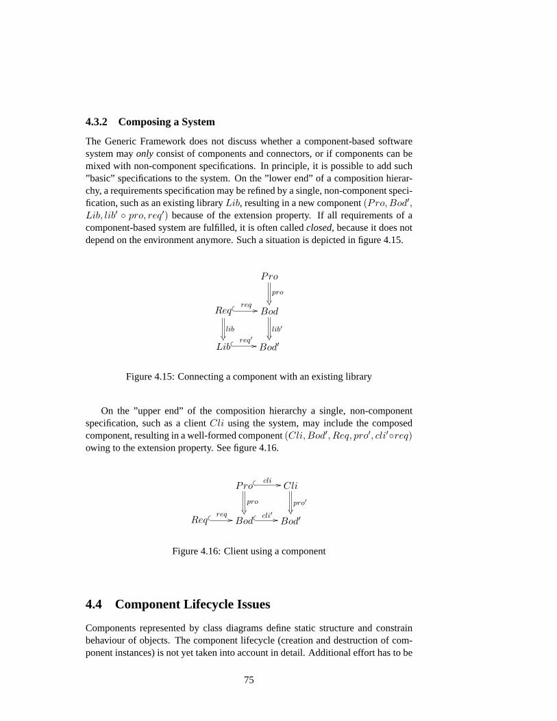
4.3.2 Composing a System
The Generic Framework does not discuss whether a component-based softwaresystem mayonly consist of components and connectors, or if components can bemixed with non-component specifications. In principle, it is possible to add such”basic” specifications to the system. On the ”lower end” of a composition hierar-chy, a requirements specification may be refined by a single, non-component speci-fication, such as an existing libraryLib, resulting in a new component(Pro, Bod′,Lib, lib′ ◦ pro, req′) because of the extension property. If all requirements of acomponent-based system are fulfilled, it is often calledclosed, because it does notdepend on the environment anymore. Such a situation is depicted in figure4.15.
Pro
pro
®¶Req
lib®
� � req // Bod
lib′®
Lib� � req′ // Bod′
Figure 4.15:Connecting a component with an existing library
On the ”upper end” of the composition hierarchy a single, non-componentspecification, such as a clientCli using the system, may include the composedcomponent, resulting in a well-formed component(Cli,Bod′, Req, pro′, cli′◦req)owing to the extension property. See figure4.16.
Pro
pro
®
� � cli // Cli
pro′®
Req � � req // Bod� � cli′ // Bod′
Figure 4.16:Client using a component
4.4 Component Lifecycle Issues
Components represented by class diagrams define static structure and constrainbehaviour of objects. The component lifecycle (creation and destruction of com-ponent instances) is not yet taken into account in detail. Additional effort has to be
75
done in order to specify how components and contained objects can be instantiatedor destroyed. Depending on the level of detail of the models to be developed, thisinformation can either be left out completely, or can be added according to usualpatterns:
• Mark a provided class with stereotype«focalClass» ([28, section 3.14.4]).When this class is instantiated (using the programming languages’ construc-tors), all other classes needed for the component are instantiated (or existingobjects are searched and suitable ones are used). A problem arises: Sub-classes hidden in the body cannot be instantiated, but because the moment ofobject creation determines the runtime type, this would mean that the focalclass is always fully specified in the provisions.
• Add explicit creation operations to the model, for example a static (class-scope) operationinstantiateComponent(params) . This is an exampleof the well-knownfactorydesign pattern. In this case, a runtime type fromthe component body can be returned, transparent to the caller.
• The underlying component technology used for implementation defines ad-ditional operations. For example, the Enterprise Java Beans [24] componentconcept defines how lifecycle methods such asejbCreate orejbActivate
can be created by a tool automatically. In the CORBA Component Model[12], a so-calledcomponent homeis declared for each component, also aimedat automatically deriving lifecycle operations.
In each of the cases mentioned, component destruction works analogously. It isimaginable that an appropriate modelling tool would either create such lifecyclefunctionality automatically or at least assist the user to create it.
76
Chapter 5
UML Case Study in ProductionAutomation
In this chapter, some work done in the IOSIP1 project is presented and adapted tothe component syntax used in this thesis. There were only few changes to be made,because a very similar notion of component was used. First, an overview of the do-main (a production automation system) is given. Then, the specified componentsare presented; some in full detail and others only partially. Finally, application ofthe partial composition operation is illustrated by explicitly showing some com-posed components.
Not all components are given in full detail. The components presented herewere not chosen on their importance for the domain, but rather on syntacticallyinteresting details. In particular, the components specifying the communicationbetween H-AGVs are shown more explicitly than the components specifying themain (negotiation and transportation) functionality, although there are more inter-esting algorithms in the latter.
The IOSIP case study also includes an analysis model of the domain, consistingof a coarse class diagram, use case diagrams and activity diagrams with naturallanguage descriptions. This part is not presented here, because in this thesis thefocus is set on the parts of a model that is modelled precisely. Nevertheless, thisanalysis model is an important part of the case study.
5.1 The Production Environment
A production system as it could be used in an automobile factory is specified in [3].Tool machines drill and wash workpieces, an input stock stores unprocessed work-pieces, an output stock stores processed workpieces. A possible layout is sketchedin figure5.1. The most interesting feature are so-calledholonic automated guided
1Integration of object-oriented software specification techniques and their application-specificextension for industrial production systems on the example of automobile industry
77
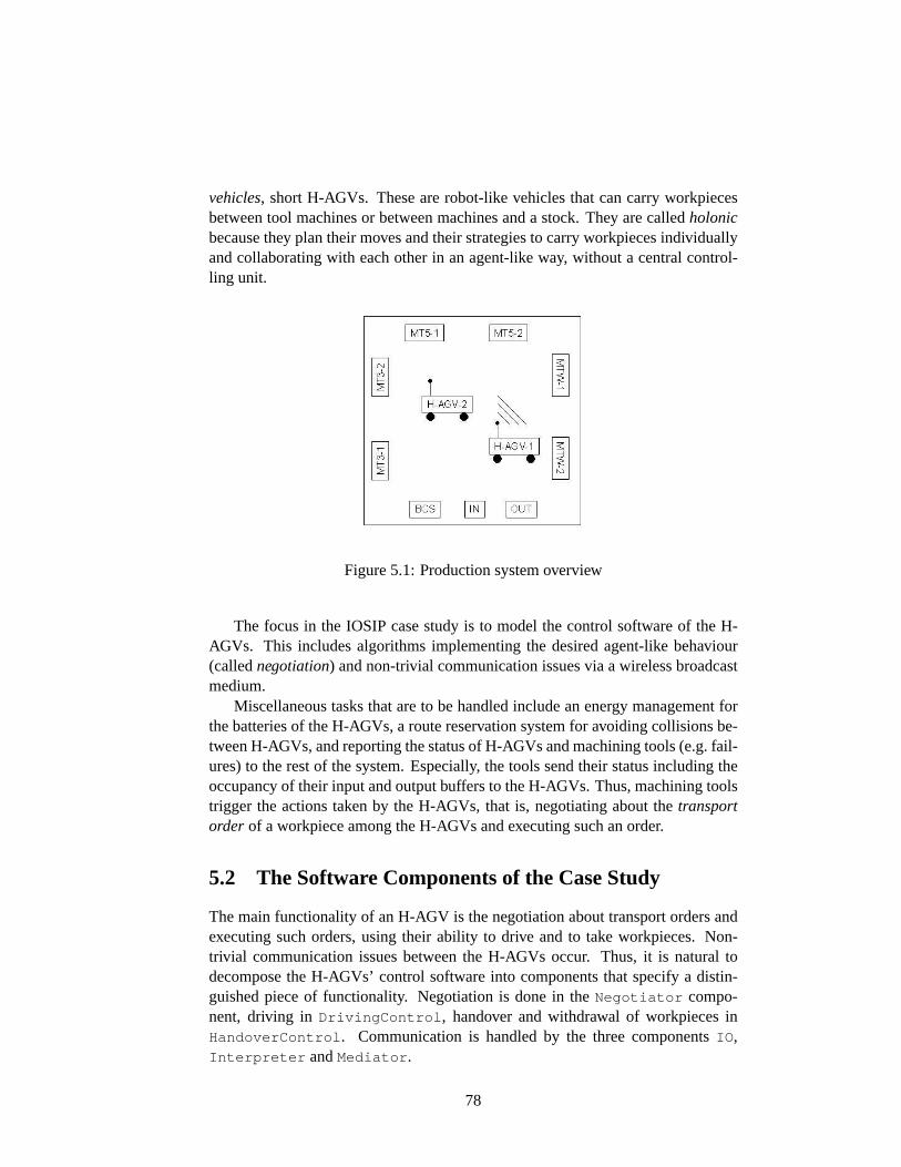
vehicles, short H-AGVs. These are robot-like vehicles that can carry workpiecesbetween tool machines or between machines and a stock. They are calledholonicbecause they plan their moves and their strategies to carry workpieces individuallyand collaborating with each other in an agent-like way, without a central control-ling unit.
Figure 5.1:Production system overview
The focus in the IOSIP case study is to model the control software of the H-AGVs. This includes algorithms implementing the desired agent-like behaviour(callednegotiation) and non-trivial communication issues via a wireless broadcastmedium.
Miscellaneous tasks that are to be handled include an energy management forthe batteries of the H-AGVs, a route reservation system for avoiding collisions be-tween H-AGVs, and reporting the status of H-AGVs and machining tools (e.g. fail-ures) to the rest of the system. Especially, the tools send their status including theoccupancy of their input and output buffers to the H-AGVs. Thus, machining toolstrigger the actions taken by the H-AGVs, that is, negotiating about thetransportorder of a workpiece among the H-AGVs and executing such an order.
5.2 The Software Components of the Case Study
The main functionality of an H-AGV is the negotiation about transport orders andexecuting such orders, using their ability to drive and to take workpieces. Non-trivial communication issues between the H-AGVs occur. Thus, it is natural todecompose the H-AGVs’ control software into components that specify a distin-guished piece of functionality. Negotiation is done in theNegotiator compo-nent, driving inDrivingControl , handover and withdrawal of workpieces inHandoverControl . Communication is handled by the three componentsIO ,Interpreter andMediator .
78

Before describing the components in detail, a shared packageTypeDefinitions containing basic types is shown. Figure5.2shows an excerpt:classes that are used in various components, and that do not define functionalitycomplex enough to be worth to be specified in detail in a component. Syntactically,one can imagine that each component has an additional requirements package con-taining used data types, and which is connected with this package. This is left outin all components for visual clarity.
Message
MessageID NegotiationID
Header Data
header
content
messageID
ID
referenceID sender receiver
+hagvID : ID
TransportOrder MachineState
Offer
Figure 5.2:Data types used commonly
The Negotiator Component
The negotiation strategy of an H-AGV is realised in theNegotiator component.Negotiation about a transport order is triggered by a message sent by a tool ma-chine, containing information that the input buffer of this machine is empty. Thismeans that the machine is ready to process a new workpiece. The negotiation al-gorithm has to decide which of the H-AGVs (excluding those in standby or failuremode) executes the transport order. Executing a transport order means driving tothe place where the workpiece is (input stock or a machine’s output buffer), with-drawing it from there, carrying it to the next position (input buffer of the nextmachine, or output stock) and handing it over there.
The negotiation algorithm is as follows: The machine state, sent by broadcast,is received by at least one H-AGV. If the machine state implies a transport order,one H-AGV becomes themoderatorof the negotiation. It calculates an expensefactor for this transport order, which may be calculated from the distance to themachine, on the battery status or any additional criterion. Thisinitial offer is sentto all other H-AGVs. H-AGVs receiving this offer calculate an offer with theirown expense factor, and send it back to the moderator if it is better. The moderatorchooses the best of all offers andassignsthe transport order to the H-AGV withthe best offer.
The corresponding classes are described now, see figure5.3. In the provisions,classNegotiator exposes two signal receptionsprocessMachineState andprocessOffer . Signal receptions are similar to regular operations, but behave
79
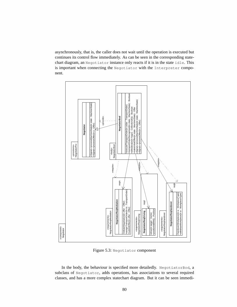
asynchronously, that is, the caller does not wait until the operation is executed butcontinues its control flow immediately. As can be seen in the corresponding state-chart diagram, anNegotiator instance only reacts if it is in the stateidle . Thisis important when connecting theNegotiator with the Interpreter compo-nent.
«req
uire
men
ts»
Neg
otia
torR
eqM
edia
tion
«pro
visi
ons»
N
egot
iato
rPro
«com
pone
nt»
Neg
otia
tor
«bod
y»
Neg
otia
torB
od
«req
uire
»
«pro
vide
»
«req
uire
men
ts»
Neg
otia
torR
eqD
rivin
g «r
equi
re»
«req
uire
men
ts»
Neg
otia
torR
eqH
ando
ver
«req
uire
»
+in
itiat
eNeg
otia
tion(
in o
ffer
: Offe
r)
+as
sign
Tra
nspo
rtO
rder
(in to
: T
rans
port
Ord
er)
+su
bmitO
ffer(
in o
ffer
: Offe
r)
Neg
oti
ato
rReq
Med
iati
on
+dr
ive(
in ta
rget
: V
ertix
) +
posi
tionI
nBR
M()
: P
ositi
on
Neg
oti
ato
rReq
Dri
vin
g
+ha
ndov
erW
orkp
iece
(in w
: W
orkp
iece
Typ
e)
+w
ithdr
awW
orkp
iece
(in w
: W
orkp
iece
Typ
e)
Neg
oti
ato
rReq
Han
do
ver
«Sig
nal»
+pr
oces
sMac
hine
Sta
te(in
sta
te :
Mac
hine
Sta
te)
«Sig
nal»
+pr
oces
sOffe
r(in
o :
Offe
r)
Neg
oti
ato
r
+ex
ecut
eTra
nspo
rtO
rder
(in o
rder
: T
rans
port
Ord
er)
+tr
ansp
ortO
rder
Rec
ogni
sed(
in s
tate
: M
ac hi
neS
tate
) : B
oole
an
+is
Mod
erat
or(in
hag
vs :
Col
lect
ion(
ID))
: B
oole
an
+m
akeI
nitia
lOffe
r(in
sta
te :
Mac
hine
Sta
te)
: Offe
r «S
igna
l»+
proc
essM
achi
neS
tate
(in s
tate
: M
achi
neS
tate
) «S
igna
l»+
proc
essO
ffer(
in o
: O
ffer)
Neg
oti
ato
rBo
d
reqm
reqd
reqh
Figure 5.3:Negotiator component
In the body, the behaviour is specified more detailedly.NegotiatorBod , asubclass ofNegotiator , adds operations, has associations to several requiredclasses, and has a more complex statechart diagram. But it can be seen immedi-
80
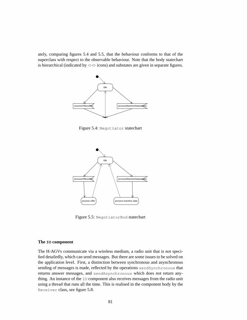
ately, comparing figures5.4 and5.5, that the behaviour conforms to that of thesuperclass with respect to the observable behaviour. Note that the body statechartis hierarchical (indicated by icons) and substates are given in separate figures.
idle
processOffer(offer) processMachineState(state)
Figure 5.4:Negotiator statechart
idle
processOffer(offer) processMachineState(state)
process offer process machine state
Figure 5.5:NegotiatorBod statechart
The IO component
The H-AGVs communicate via a wireless medium, a radio unit that is not speci-fied detailedly, which can send messages. But there are some issues to be solved onthe application level. First, a distinction between synchronous and asynchronoussending of messages is made, reflected by the operationssendSynchronous thatreturns answer messages, andsendAsynchronous which does not return any-thing. An instance of theIO component also receives messages from the radio unitusing a thread that runs all the time. This is realised in the component body by theReceiver class, see figure5.8.
81
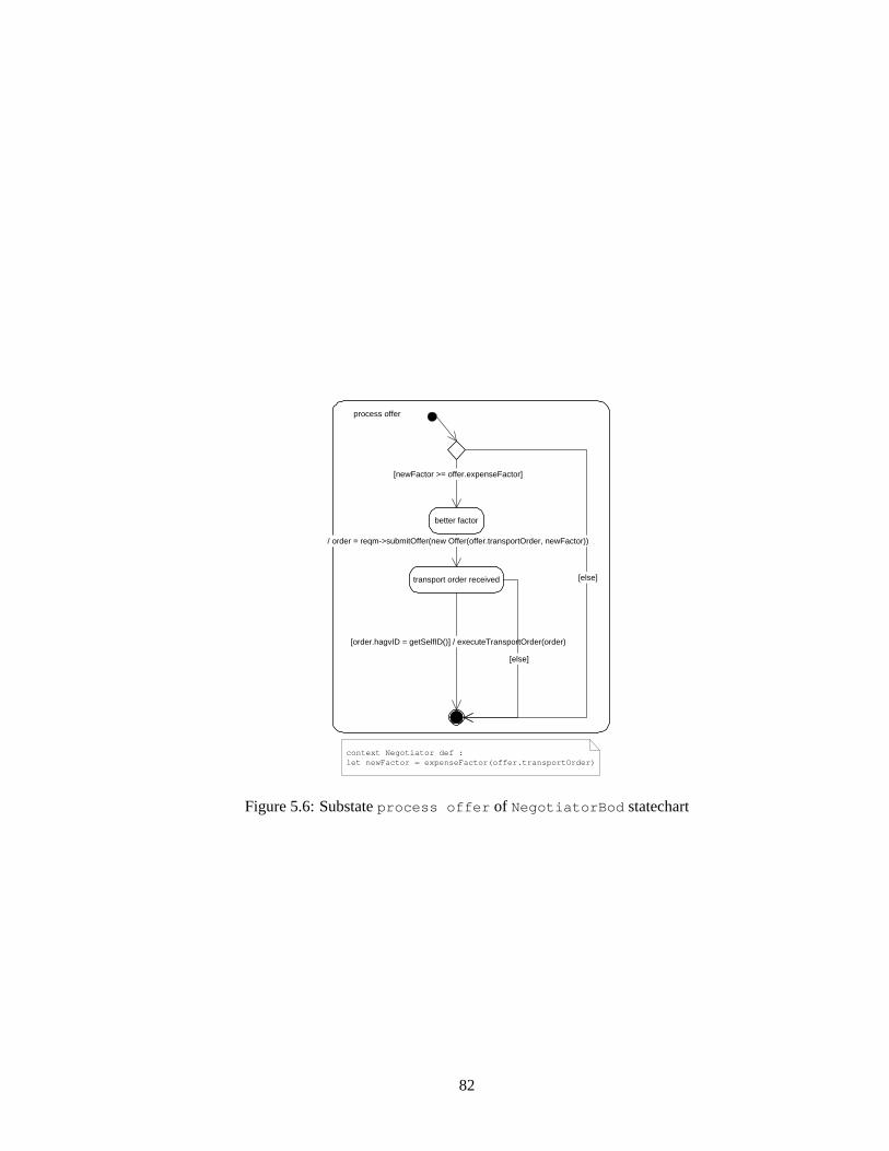
better factor
process offer
[newFactor >= offer.expenseFactor]
[else]
context Negotiator def : let newFactor = expenseFactor(offer.transportOrder)
/ order = reqm->submitOffer(new Offer(offer.transportOrder, newFactor))
transport order received
[order.hagvID = getSelfID()] / executeTransportOrder(order)
[else]
Figure 5.6:Substateprocess offer of NegotiatorBod statechart
82
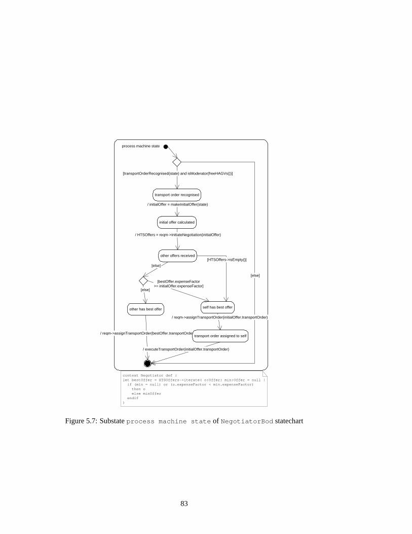
transport order recognised
process machine state
[transportOrderRecognised(state) and isModerator(freeHAGVs())]
[else]
/ initialOffer = makeInitialOffer(state)
initial offer calculated
[else]
[HTSOffers->isEmpty()] other offers received
/ HTSOffers = reqm->initiateNegotiation(initialOffer)
self has best offer other has best offer
[else]
[bestOffer.expenseFactor >= initialOffer.expenseFactor]
/ reqm->assignTransportOrder(bestOffer.transportOrder)
/ reqm->assignTransportOrder(initialOffer.transportOrder)
transport order assigned to self
/ executeTransportOrder(initialOffer.transportOrder)
context Negotiator def : let bestOffer = HTSOffers->iterate( o:Offer; min:Offer = null | if (min = null) or (o.expenseFactor < min.expenseFactor) then o else minOffer endif )
Figure 5.7:Substateprocess machine state of NegotiatorBod statechart
83
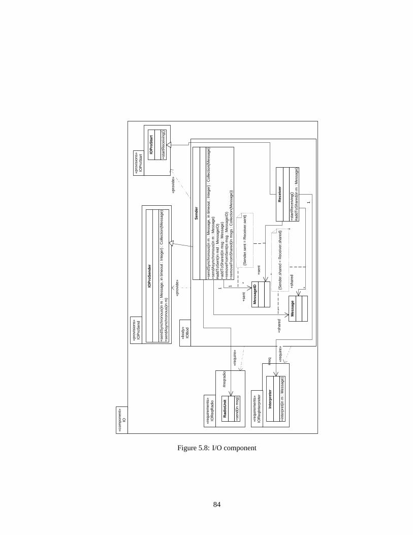
«pro
vide
»
«com
pone
nt»
IO
«req
uire
men
ts»
IOR
eqR
adio
«pro
visi
ons»
IO
Pro
Sta
rt
+st
artR
ecei
ving
()
#add
ToS
hare
d(in
m :
Mes
sage
)
Rec
eive
r
Mes
sag
e Mes
sag
eID
+se
ndS
ynch
rono
us(in
m :
Mes
sage
, in
timeo
ut :
Inte
ger)
: C
olle
ctio
n(M
essa
ge)
+se
ndA
sync
hron
ous(
in m
: M
essa
ge)
#add
ToS
ent(
in m
id :
Mes
sage
ID)
+ad
dToS
hare
d(in
msg
: M
essa
ge)
+re
mov
eFro
mS
ent(
in m
sg :
Mes
sage
ID)
+re
mov
eFro
mS
hare
d(in
msg
s : C
olle
ctio
n(M
essa
ge))
Sen
der
+se
nt
*
1
+se
nt
*
1
{Sen
der.
sent
= R
ecei
ver.
sent
}
+sh
ared
*
1 +sh
ared
* 1
{Sen
der.
shar
ed =
Rec
eive
r.sh
ared
}
+se
ndS
ynch
rono
us(in
m :
Mes
sage
, in
timeo
ut :
Inte
ger)
: C
olle
ctio
n(M
essa
ge)
+se
ndA
sync
hron
ous(
in m
)
IOP
roS
end
er
+st
artR
ecei
ving
()
IOP
roS
tart
+in
terp
ret(
in m
: M
essa
ge)
Inte
rpre
ter
+se
nd(in
msg
)
Rad
ioU
nit
«req
uire
»
«pro
vide
»
#req
radi
o
«pro
visi
ons»
IO
Pro
Sen
d
«bod
y»
IOB
od
#req
«req
uire
»
«req
uire
men
ts»
IOR
eqIn
terp
rete
r
Figure 5.8:I/O component
84
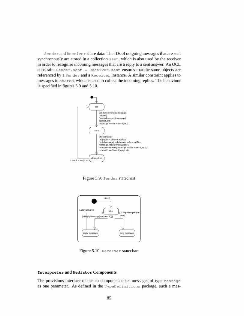
Sender andReceiver share data: The IDs of outgoing messages that are sentsynchronously are stored in a collectionsent , which is also used by the receiverin order to recognise incoming messages that are a reply to a sent answer. An OCLconstraintSender.sent = Receiver.sent ensures that the same objects arereferenced by aSender and aReceiver instance. A similar constraint applies tomessages inshared , which is used to collect the incoming replies. The behaviouris specified in figures5.9and5.10.
idle
sent
cleaned up
sendSynchronous(message, timeout) / reqradio->send(message); addToSent( message.header.messageID)
after(timeout) / replyList = shared->select( reply:Message|reply.header.referenceID = message.header.messageID); removeFromSent(message.header.messageID); removeFromShared(replyList)
/ result = replyList
Figure 5.9:Sender statechart
idle
start()
reply message new message
[isReplyMessage(input.read())] [else]
/ addToShared / req->interpret(m)
Figure 5.10:Receiver statechart
Interpreter and Mediator Components
The provisions interface of theIO component takes messages of typeMessage
as one parameter. As defined in theTypeDefinitions package, such a mes-
85
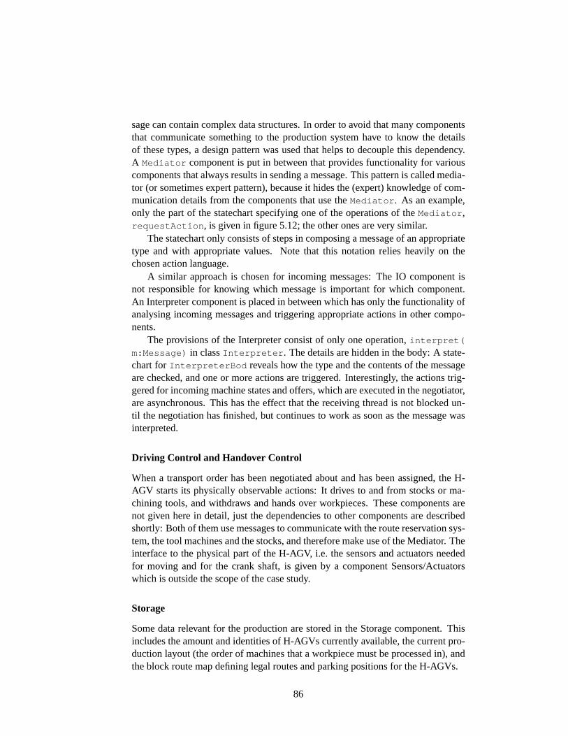
sage can contain complex data structures. In order to avoid that many componentsthat communicate something to the production system have to know the detailsof these types, a design pattern was used that helps to decouple this dependency.A Mediator component is put in between that provides functionality for variouscomponents that always results in sending a message. This pattern is called media-tor (or sometimes expert pattern), because it hides the (expert) knowledge of com-munication details from the components that use theMediator . As an example,only the part of the statechart specifying one of the operations of theMediator ,requestAction , is given in figure5.12; the other ones are very similar.
The statechart only consists of steps in composing a message of an appropriatetype and with appropriate values. Note that this notation relies heavily on thechosen action language.
A similar approach is chosen for incoming messages: The IO component isnot responsible for knowing which message is important for which component.An Interpreter component is placed in between which has only the functionality ofanalysing incoming messages and triggering appropriate actions in other compo-nents.
The provisions of the Interpreter consist of only one operation,interpret(
m:Message) in classInterpreter . The details are hidden in the body: A state-chart forInterpreterBod reveals how the type and the contents of the messageare checked, and one or more actions are triggered. Interestingly, the actions trig-gered for incoming machine states and offers, which are executed in the negotiator,are asynchronous. This has the effect that the receiving thread is not blocked un-til the negotiation has finished, but continues to work as soon as the message wasinterpreted.
Driving Control and Handover Control
When a transport order has been negotiated about and has been assigned, the H-AGV starts its physically observable actions: It drives to and from stocks or ma-chining tools, and withdraws and hands over workpieces. These components arenot given here in detail, just the dependencies to other components are describedshortly: Both of them use messages to communicate with the route reservation sys-tem, the tool machines and the stocks, and therefore make use of the Mediator. Theinterface to the physical part of the H-AGV, i.e. the sensors and actuators neededfor moving and for the crank shaft, is given by a component Sensors/Actuatorswhich is outside the scope of the case study.
Storage
Some data relevant for the production are stored in the Storage component. Thisincludes the amount and identities of H-AGVs currently available, the current pro-duction layout (the order of machines that a workpiece must be processed in), andthe block route map defining legal routes and parking positions for the H-AGVs.
86
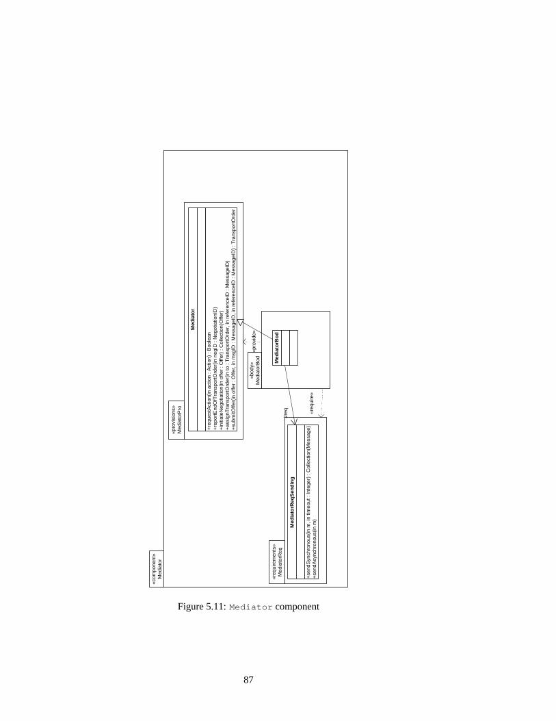
«pro
vide
»
«com
pone
nt»
Med
iato
r
«req
uire
men
ts»
Med
iato
rReq
«pro
visi
ons»
M
edia
torP
ro
«bod
y»
Med
iato
rBod
«req
uire
»
+re
ques
tAct
ion(
in a
ctio
n : A
ctio
n) :
Boo
lean
+
repo
rtE
ndO
fTra
nspo
rtO
rder
(in n
egID
: N
egot
iatio
nID
) +
initi
ateN
egot
iatio
n(in
offe
r : O
ffer)
: C
olle
ctio
n(O
ffer)
+
assi
gnT
rans
port
Ord
er(in
to :
Tra
nspo
rtO
rder
, in
refe
renc
eID
: M
essa
geID
) +
subm
itOffe
r(in
offe
r : O
ffer,
in m
sgID
: M
essa
geID
, in
refe
renc
eID
: M
essa
geID
) : T
rans
port
Ord
er
Med
iato
r
Med
iato
rBo
d
+se
ndS
ynch
rono
us(in
m, i
n tim
eout
: In
tege
r) :
Col
lect
ion(
Mes
sage
) +
send
Asy
nchr
onou
s(in
m)
Med
iato
rReq
Sen
din
g
#req
Figure 5.11:Mediator component
87
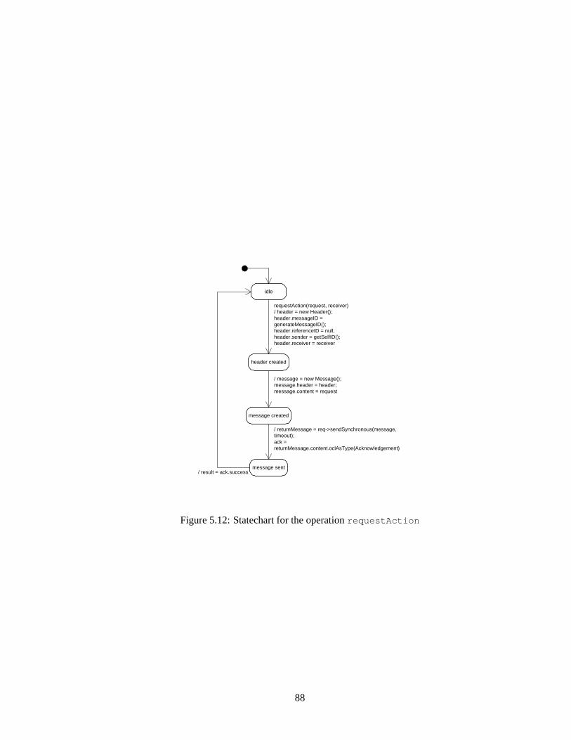
idle
header created
message created
message sent
requestAction(request, receiver) / header = new Header(); header.messageID = generateMessageID(); header.referenceID = null; header.sender = getSelfID(); header.receiver = receiver
/ message = new Message(); message.header = header; message.content = request
/ returnMessage = req->sendSynchronous(message, timeout); ack = returnMessage.content.oclAsType(Acknowledgement)
/ result = ack.success
Figure 5.12:Statechart for the operationrequestAction
88
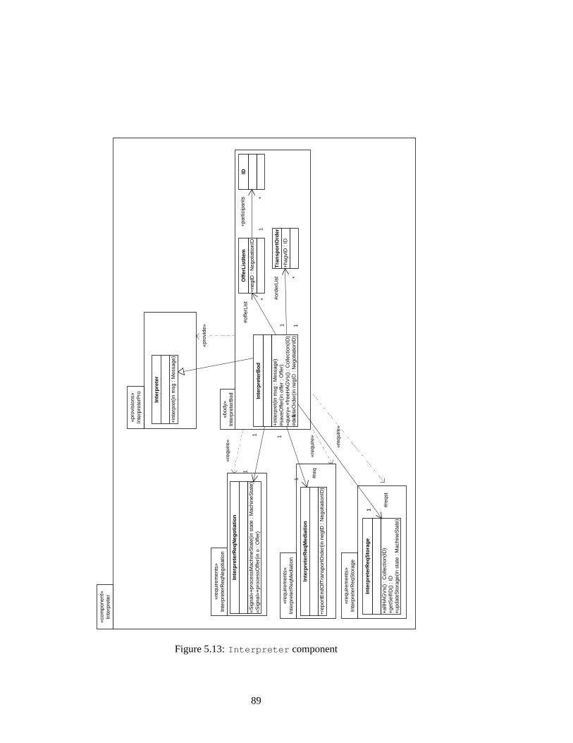
«req
uire
men
ts»
Inte
rpre
terR
eqN
egot
iatio
n
«pro
visi
ons»
In
terp
rete
rPro
«com
pone
nt»
Inte
rpre
ter
«bod
y»
Inte
rpre
terB
od
+in
terp
ret(
in m
sg :
Mes
sage
) #s
aveO
ffer(
in o
ffer
: Offe
r)
«que
ry»
+fr
eeH
AG
Vs(
) : C
olle
ctio
n(ID
) #d
elet
eOrd
er(in
neg
ID :
Neg
otia
tionI
D)
Inte
rpre
terB
od
+in
terp
ret(
in m
sg :
Mes
sage
)
Inte
rpre
ter
+ne
gID
: N
egot
iatio
nID
Off
erL
istI
tem
1
#offe
rLis
t *
+ha
gvID
: ID
Tra
nsp
ort
Ord
er
1
#ord
erLi
st *
ID
1
+pa
rtic
ipan
ts *
«req
uire
»
«pro
vide
»
«Sig
nal»
+pr
oces
sMac
hine
Sta
te(in
sta
te :
Mac
hine
Sta
te)
«Sig
nal»
+pr
oces
sOffe
r(in
o :
Offe
r)
Inte
rpre
terR
eqN
ego
tiat
ion
1
#req
1
«req
uire
men
ts»
Inte
rpre
terR
eqM
edia
tion
«req
uire
»
+re
port
End
OfT
rans
port
Ord
er(in
neg
ID :
Neg
otia
tionI
D)
Inte
rpre
terR
eqM
edia
tio
n
+al
lHA
GV
s()
: Col
lect
ion(
ID)
+ge
tSel
fID()
: ID
+
upda
teS
tora
ge(in
sta
te :
Mac
hine
Sta
te)
Inte
rpre
terR
eqS
tora
ge
1
#req
st
1
«req
uire
men
ts»
Inte
rpre
terR
eqS
tora
ge
«req
uire
»
1
1
Figure 5.13:Interpreter component
89
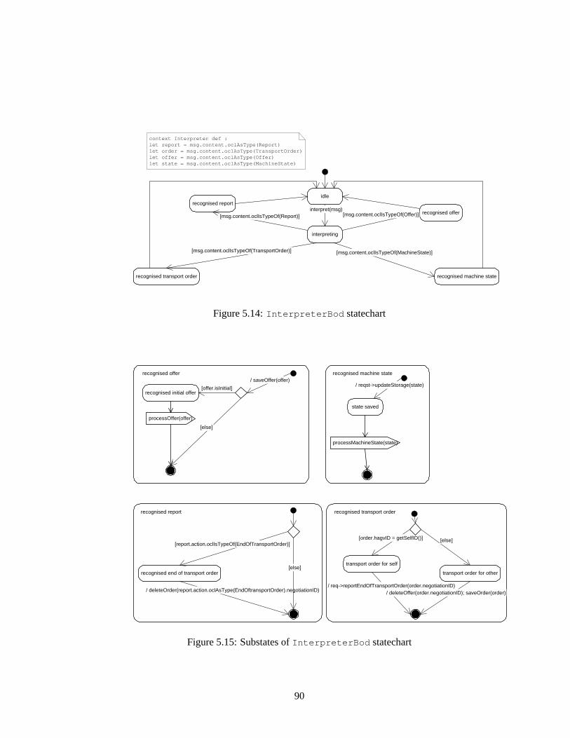
idle
recognised transport order
recognised offer
recognised machine state
recognised report
interpreting
interpret(msg) [msg.content.oclIsTypeOf(Report)]
[msg.content.oclIsTypeOf(TransportOrder)]
[msg.content.oclIsTypeOf(Offer)]
[msg.content.oclIsTypeOf(MachineState)]
context Interpreter def : let report = msg.content.oclAsType(Report) let order = msg.content.oclAsType(TransportOrder) let offer = msg.content.oclAsType(Offer) let state = msg.content.oclAsType(MachineState)
Figure 5.14:InterpreterBod statechart
recognised end of transport order
[report.action.oclIsTypeOf(EndOfTransportOrder)]
/ deleteOrder(report.action.oclAsType(EndOftransportOrder).negotiationID)
[else]
recognised report
transport order for self
[order.hagvID = getSelfID()]
/ req->reportEndOfTransportOrder(order.negotiationID)
[else]
recognised transport order
transport order for other
/ deleteOffer(order.negotiationID); saveOrder(order)
recognised initial offer
recognised offer / saveOffer(offer)
[offer.isInitial]
[else]
processOffer(offer)
state saved
recognised machine state
/ reqst->updateStorage(state)
processMachineState(state)
Figure 5.15:Substates ofInterpreterBod statechart
90

5.3 Composing the Software System
As soon as the components are specified, their interconnection can be defined. Inmost cases, we have trivial connectors only, because requirements classes and cor-responding provisions classes have equal signatures. In these cases, just a renaming(alias) of classes has to be defined.
In a development environment with appropriate tools, no further work wouldhave to be done because the resulting component could be calculated automatically.In order to get an impression of what partial hierarchical composition is all about,some compositions will be shown in detail.
The three components that deal with communication issues, IO, Interpreter andMediator, can be composed to a single larger component which will be called Com-munication. The following connectors are needed:IOReqInterpreter is ful-filled with InterpreterPro , where classIOReqInterpreter::Interpreter
can be identified with (or renamed to)InterpreterPro::Interpreter .InterpreterReqMediation is fulfilled by MediatorPro , because class
MediatorPro::Mediator can be a subclass ofInterpreterReqMediation::
InterpreterReqMediation as it has the desired operationreportEndOfTransportOrder(negID:NegotiationID) .
MediatorReq is fulfilled by IOProSending because of identical signaturesof classesMediatorReqSending andIOProSender .
IOReqRadio is not fulfilled and thus becomes an open requirements part of thecommunication component, but is renamed toCommunicationReqRadio . Thissimilarly applies toInterpreterReqNegotiation andInterpreterReqStorage .
The composed component is given in figure5.16, its body is given in detail infigure5.17.
A similar structure is gained when composing the components Negotiator, Han-doverControl and DrivingControl to a component Production, see figure5.18. Inthis case, five requirements packages are left open, and one provisions package isexposed to the environment.
The Communication and Production components can be composed mutuallyand with Storage, RadioUnit, and SensorsActuators accordingly, thus gaining acomplete model of the system. In figure5.19, the resulting system is given withinsight into the components. If we abstract even one level higher, hiding all com-ponent contents, a very compact overview of the system results (figure5.20). Thenotation for the latter, though, is not strictly correct as the«provide» depen-dency should be used to connect provisions and requirements parts rather thancomponents.
5.3.1 Behavioural Composition
As stated before, there is no action language defined in the UML. But it should beobvious that an action that represents a method call on another object synchronises
91

«com
pone
nt»
IO
«com
pone
nt»
Com
mun
icat
ion
«req
uire
men
ts»
Com
mun
icat
ionR
eqN
egot
iatio
n
«req
uire
men
ts»
Com
mun
icat
ionR
eqS
tora
ge
«req
uire
men
ts»
Com
mun
icat
ionR
eqR
adio
«bod
y»
Com
mun
icat
ionB
od
«com
pone
nt»
Med
iato
r
«req
uire
men
ts»
Med
iato
rReq
«pro
visi
ons»
M
edia
torP
ro
«bod
y»
Med
iato
rBod
«req
uire
men
ts»
IOR
eqR
adio
«pro
visi
ons»
IO
Pro
Sta
rt
«pro
visi
ons»
IO
Pro
Sen
d «bod
y»
IOB
od
«req
uire
men
ts»
IOR
eqIn
terp
rete
r
«pro
visi
ons»
In
terp
rete
rPro
«bod
y»
Inte
rpre
terB
od
«req
uire
men
ts»
Inte
rpre
terR
eqM
edia
tion
«req
uire
men
ts»
Inte
rpre
terR
eqS
tora
ge
«pro
vide
»
«req
uire
»
«pro
vide
»
«req
uire
»
«pro
vide
»
«pro
vide
»
«req
uire
»
«req
uire
»
«req
uire
»
«pro
vide
»
«pro
vide
»
«req
uire
men
ts»
Inte
rpre
terR
eqN
egot
iatio
n
«req
uire
»
«pro
vide
»
«com
pone
nt»
Inte
rpre
ter
«pro
visi
ons»
C
omm
unic
atio
nPro
Sta
rt
«pro
vide
» [C
omm
unic
atio
nPro
Sta
rt /
IOP
roS
tart
]
«req
uire
» [C
omm
unic
atio
nReq
Rad
io /
IOR
eqR
adio
]
«req
uire
» [C
omm
unic
atio
nReq
Sto
rage
/ In
terp
rete
rReq
Sto
rage
]
«req
uire
» [C
omm
unic
atio
nReq
Neg
otia
tion
/ Int
erpr
eter
Req
Neg
otia
tion]
«pro
visi
ons»
C
omm
unic
atio
nPro
Med
iatio
n
«pro
vide
» [C
omm
unic
atio
nPro
Med
iatio
n / M
edia
torP
ro]
Figure 5.16:Communication component
92
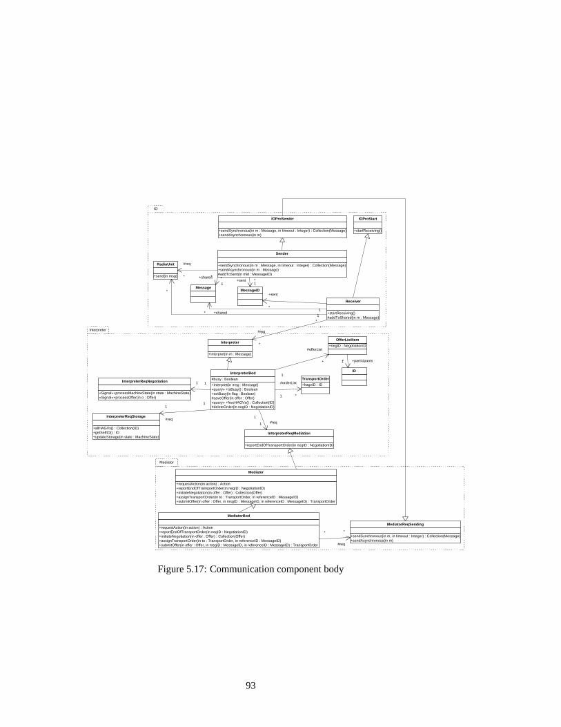
Mediator
+sendSynchronous(in m : Message, in timeout : Integer) : Collection(Message) +sendAsynchronous(in m : Message) #addToSent(in mid : MessageID)
Sender
+sendSynchronous(in m : Message, in timeout : Integer) : Collection(Message) +sendAsynchronous(in m)
IOProSender
+startReceiving() #addToShared(in m : Message)
Receiver
+startReceiving()
IOProStart
+interpret(in m : Message)
Interpreter
#req
*
*
+interpret(in msg : Message) «query» +isBusy() : Boolean +setBusy(in flag : Boolean) #saveOffer(in offer : Offer) «query» +freeHAGVs() : Collection(ID) #deleteOrder(in negID : NegotiationID)
#busy : Boolean
InterpreterBod
«Signal»+processMachineState(in state : MachineState) «Signal»+processOffer(in o : Offer)
InterpreterReqNegotiation 1 1
+reportEndOfTransportOrder(in negID : NegotiationID)
InterpreterReqMediation
1 #req 1
+allHAGVs() : Collection(ID) +getSelfID() : ID +updateStorage(in state : MachineState)
InterpreterReqStorage
1
#req
1
+requestAction(in action) : Action +reportEndOfTransportOrder(in negID : NegotiationID) +initiateNegotiation(in offer : Offer) : Collection(Offer) +assignTransportOrder(in to : TransportOrder, in referenceID : MessageID) +submitOffer(in offer : Offer, in msgID : MessageID, in referenceID : MessageID) : TransportOrder
Mediator
+requestAction(in action) : Action +reportEndOfTransportOrder(in negID : NegotiationID) +initiateNegotiation(in offer : Offer) : Collection(Offer) +assignTransportOrder(in to : TransportOrder, in referenceID : MessageID) +submitOffer(in offer : Offer, in msgID : MessageID, in referenceID : MessageID) : TransportOrder
MediatorBod
+sendSynchronous(in m, in timeout : Integer) : Collection(Message) +sendAsynchronous(in m)
MediatorReqSending
#req
* *
MessageID +sent
* 1
+sent * 1
Message
+shared *
1
+shared * 1
ID
+hagvID : ID
TransportOrder
1
#orderList
*
+negID : NegotiationID
OfferListItem
1
#offerList
* 1 +participants *
+send(in msg)
RadioUnit
*
*
#req
* *
IO
Interpreter
Figure 5.17:Communication component body
93
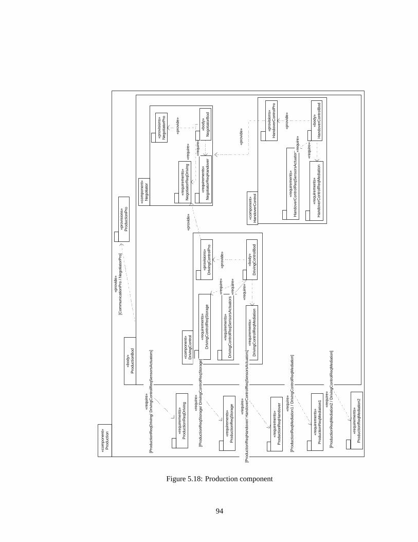
«com
pone
nt»
Neg
otia
tor
«com
pone
nt»
Pro
duct
ion «r
equi
rem
ents
» P
rodu
ctio
nReq
Med
iatio
n2
«req
uire
men
ts»
Pro
duct
ionR
eqH
ando
ver
«req
uire
men
ts»
Pro
duct
ionR
eqS
tora
ge
«bod
y»
Pro
duct
ionB
od
«req
uire
men
ts»
Neg
otia
torR
eqD
rivin
g
«pro
visi
ons»
N
egot
iato
rPro
«bod
y»
Neg
otia
torB
od
«req
uire
men
ts»
Neg
otia
torR
eqH
ando
ver
«pro
visi
ons»
H
ando
verC
ontr
olP
ro
«bod
y»
Han
dove
rCon
trol
Bod
«r
equi
rem
ents
» H
ando
verC
ontr
olR
eqM
edia
tion
«req
uire
men
ts»
Han
dove
rCon
trol
Req
Sen
sors
Act
uato
rs
«pro
vide
»
«req
uire
»
«pro
vide
»
«req
uire
»
«pro
vide
»
«req
uire
»
«req
uire
»
«com
pone
nt»
Han
dove
rCon
trol
«pro
visi
ons»
P
rodu
ctio
nPro
«pro
vide
» [C
omm
unic
atio
nPro
/ N
egot
iato
rPro
]
«req
uire
» [P
rodu
ctio
nReq
Med
iatio
n1 /
Driv
ingC
ontr
olR
eqM
edia
tion]
«pro
visi
ons»
D
rivin
gCon
trol
Pro
«bod
y»
Driv
ingC
ontr
olB
od
«req
uire
men
ts»
Driv
ingC
ontr
olR
eqM
edia
tion
«req
uire
men
ts»
Driv
ingC
ontr
olR
eqS
enso
rsA
ctua
tors
«pro
vide
»
«req
uire
»
«req
uire
»
«com
pone
nt»
Driv
ingC
ontr
ol
«pro
vide
»
«req
uire
men
ts»
Driv
ingC
ontr
olR
eqS
tora
ge
«req
uire
»
«req
uire
men
ts»
Pro
duct
ionR
eqD
rivin
g
«req
uire
» [P
rodu
ctio
nReq
Driv
ing/
Driv
ingC
ontr
olR
eqS
enso
rsA
ctua
tors
]
«req
uire
» [P
rodu
ctio
nReq
Sto
rage
/ Driv
ingC
ontr
olR
eqS
tora
ge]
«req
uire
» [P
rodu
ctio
nReq
Han
dove
r/ H
ando
verC
ontr
olR
eqS
enso
rsA
ctua
tors
]
«req
uire
men
ts»
Pro
duct
ionR
eqM
edia
tion1
«req
uire
» [P
rodu
ctio
nReq
Med
iatio
n2 /
Driv
ingC
ontr
olR
eqM
edia
tion]
Figure 5.18:Production component
94

«component» Storage
«component» Communication
«requirements» CommunicationReqNegotiation
«requirements» CommunicationReqStorage
«requirements» CommunicationReqRadio
«body» CommunicationBod
«provisions» CommunicationProStart
«provisions» CommunicationProMediation
«provide» «provide»
«require»
«require»
«require»
«component» Production
«body» ProductionBod
«provisions» ProductionPro
«provide»
«provide»
«require»
«provide»
«component» SensorsActuators «provisions»
StoragePro
«provisions» Handover
«provisions» Driving
«component» RadioUnit
«provisions» Sending
«connect»
«requirements» ProductionReqStorage
«provide»
«requirements» ProductionReqMediation2
«requirements» ProductionReqHandover
«requirements» ProductionReqMediation1
«provide»
«requirements» ProductionReqDriving
«provide»
«provide»
«require»
«require»
«require»
«provide»
Figure 5.19:System component
«component» Communication
«component» Production
«component» SensorsActuators
«component» Storage
«component» RadioUnit
«provide»
«provide»
«provide»
«provide» «provide» «provide»
Figure 5.20:System component – Overview
95
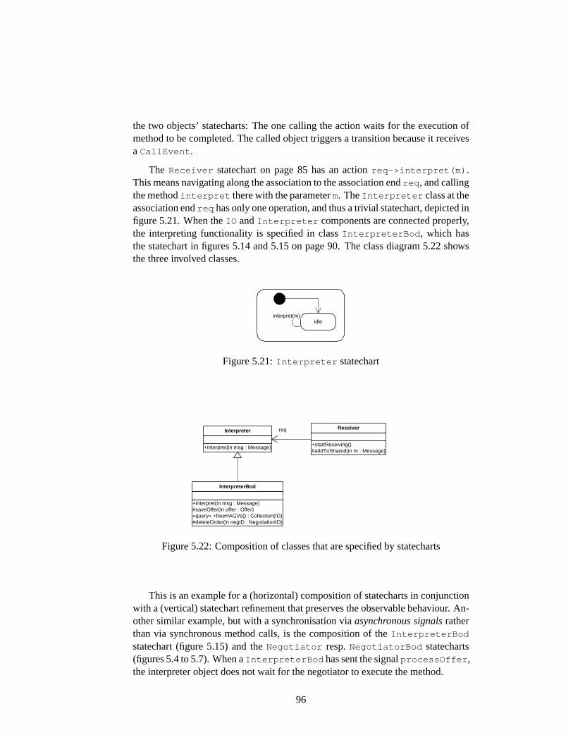
the two objects’ statecharts: The one calling the action waits for the execution ofmethod to be completed. The called object triggers a transition because it receivesa CallEvent .
The Receiver statechart on page85 has an actionreq->interpret(m) .This means navigating along the association to the association endreq , and callingthe methodinterpret there with the parameterm. TheInterpreter class at theassociation endreq has only one operation, and thus a trivial statechart, depicted infigure5.21. When theIO andInterpreter components are connected properly,the interpreting functionality is specified in classInterpreterBod , which hasthe statechart in figures5.14and5.15on page90. The class diagram5.22showsthe three involved classes.
idle interpret(m)
Figure 5.21:Interpreter statechart
+interpret(in msg : Message) #saveOffer(in offer : Offer) «query» +freeHAGVs() : Collection(ID) #deleteOrder(in negID : NegotiationID)
InterpreterBod
+interpret(in msg : Message)
Interpreter
+startReceiving() #addToShared(in m : Message)
Receiver req
Figure 5.22:Composition of classes that are specified by statecharts
This is an example for a (horizontal) composition of statecharts in conjunctionwith a (vertical) statechart refinement that preserves the observable behaviour. An-other similar example, but with a synchronisation viaasynchronous signalsratherthan via synchronous method calls, is the composition of theInterpreterBod
statechart (figure5.15) and theNegotiator resp.NegotiatorBod statecharts(figures5.4to5.7). When aInterpreterBod has sent the signalprocessOffer ,the interpreter object does not wait for the negotiator to execute the method.
96
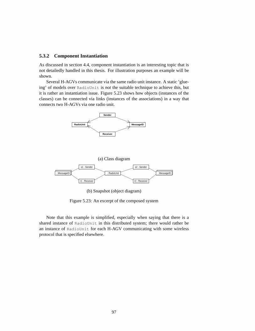
5.3.2 Component Instantiation
As discussed in section4.4, component instantiation is an interesting topic that isnot detailedly handled in this thesis. For illustration purposes an example will beshown.
Several H-AGVs communicate via the same radio unit instance. A static ’glue-ing’ of models overRadioUnit is not the suitable technique to achieve this, butit is rather an instantiation issue. Figure5.23shows how objects (instances of theclasses) can be connected via links (instances of the associations) in a way thatconnects two H-AGVs via one radio unit.
Sender
Receiver
RadioUnit MessageID
(a) Class diagram
: MessageID
s1 : Sender
r1 : Receiver
: MessageID : RadioUnit
s2 : Sender
r2 : Receiver
: MessageID : MessageID
(b) Snapshot (object diagram)
Figure 5.23:An excerpt of the composed system
Note that this example is simplified, especially when saying that there is ashared instance ofRadioUnit in this distributed system; there would rather bean instance ofRadioUnit for each H-AGV communicating with some wirelessprotocol that is specified elsewhere.
97
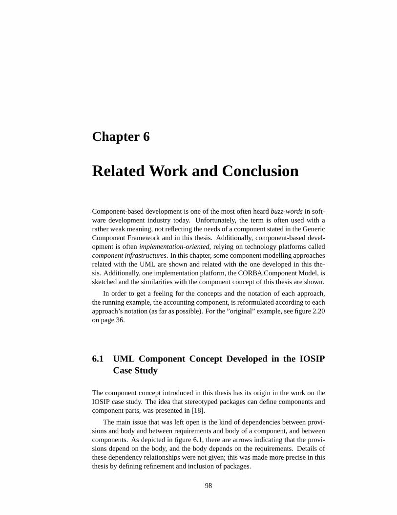
Chapter 6
Related Work and Conclusion
Component-based development is one of the most often heardbuzz-wordsin soft-ware development industry today. Unfortunately, the term is often used with arather weak meaning, not reflecting the needs of a component stated in the GenericComponent Framework and in this thesis. Additionally, component-based devel-opment is oftenimplementation-oriented, relying on technology platforms calledcomponent infrastructures. In this chapter, some component modelling approachesrelated with the UML are shown and related with the one developed in this the-sis. Additionally, one implementation platform, the CORBA Component Model, issketched and the similarities with the component concept of this thesis are shown.
In order to get a feeling for the concepts and the notation of each approach,the running example, the accounting component, is reformulated according to eachapproach’s notation (as far as possible). For the ”original” example, see figure2.20on page36.
6.1 UML Component Concept Developed in the IOSIPCase Study
The component concept introduced in this thesis has its origin in the work on theIOSIP case study. The idea that stereotyped packages can define components andcomponent parts, was presented in [18].
The main issue that was left open is the kind of dependencies between provi-sions and body and between requirements and body of a component, and betweencomponents. As depicted in figure6.1, there are arrows indicating that the provi-sions depend on the body, and the body depends on the requirements. Details ofthese dependency relationships were not given; this was made more precise in thisthesis by defining refinement and inclusion of packages.
98
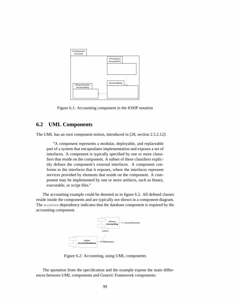
«Component» Accounts
«Provisions» AccountsPro
AccountsBody «Requirements»
AccountsReq
Figure 6.1:Accounting component in the IOSIP notation
6.2 UML Components
The UML has an own component notion, introduced in [28, section 2.5.2.12]:
”A component represents a modular, deployable, and replaceablepart of a system that encapsulates implementation and exposes a set ofinterfaces. A component is typically specified by one or more classi-fiers that reside on the component. A subset of these classifiers explic-itly defines the component’s external interfaces. A component con-forms to the interfaces that it exposes, where the interfaces representservices provided by elements that reside on the component. A com-ponent may be implemented by one or more artifacts, such as binary,executable, or script files.”
The accounting example could be denoted as in figure6.2. All defined classesreside inside the components and are typically not shown in a component diagram.The«uses» dependency indicates that the database component is required by theaccounting component.
«library» Accounting
AccountFactory
«table» AccountDatabase
«uses»
DBInterface
Figure 6.2:Accounting, using UML components
The quotation from the specification and the example expose the main differ-ences between UML components and Generic Framework components:
99
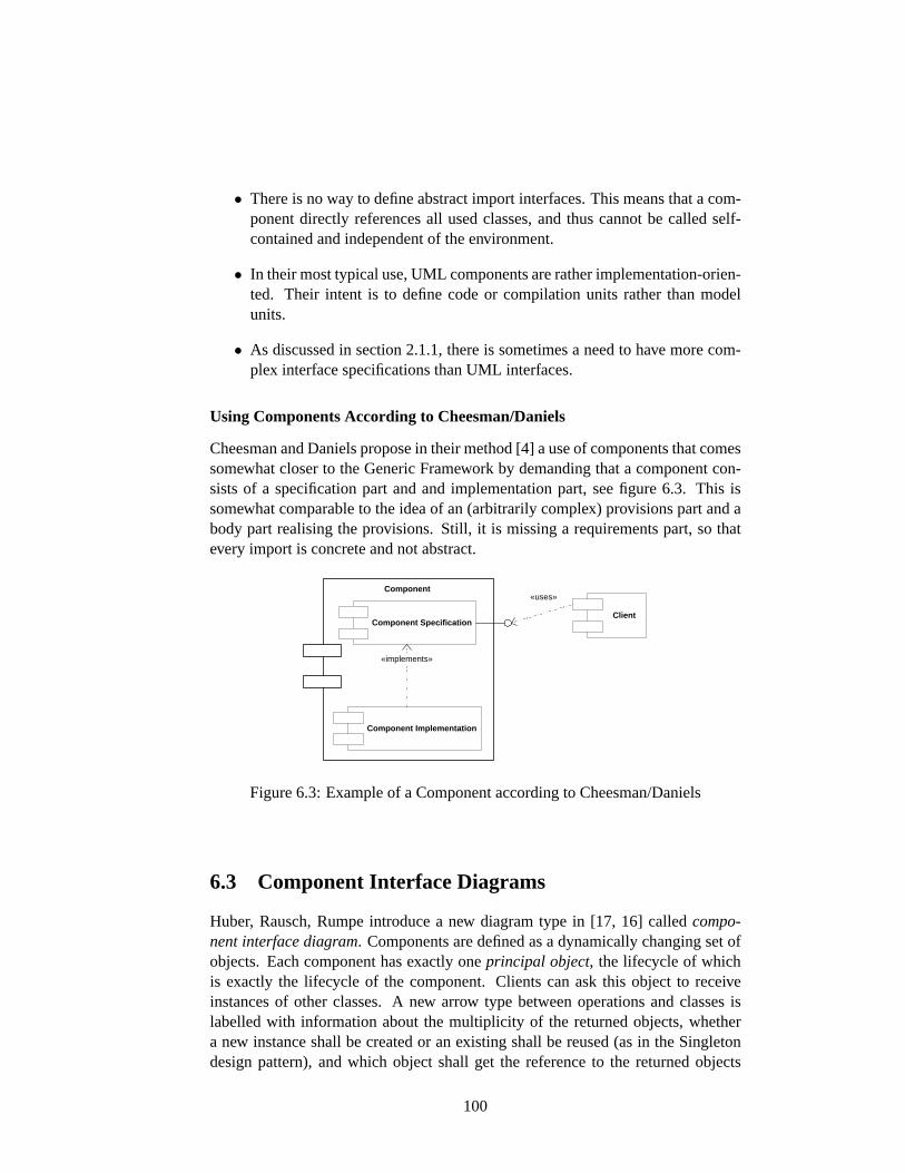
• There is no way to define abstract import interfaces. This means that a com-ponent directly references all used classes, and thus cannot be called self-contained and independent of the environment.
• In their most typical use, UML components are rather implementation-orien-ted. Their intent is to define code or compilation units rather than modelunits.
• As discussed in section2.1.1, there is sometimes a need to have more com-plex interface specifications than UML interfaces.
Using Components According to Cheesman/Daniels
Cheesman and Daniels propose in their method [4] a use of components that comessomewhat closer to the Generic Framework by demanding that a component con-sists of a specification part and and implementation part, see figure6.3. This issomewhat comparable to the idea of an (arbitrarily complex) provisions part and abody part realising the provisions. Still, it is missing a requirements part, so thatevery import is concrete and not abstract.
Component Specification
Component Implementation
«implements»
Client
«uses» Component
Figure 6.3:Example of a Component according to Cheesman/Daniels
6.3 Component Interface Diagrams
Huber, Rausch, Rumpe introduce a new diagram type in [17, 16] called compo-nent interface diagram. Components are defined as a dynamically changing set ofobjects. Each component has exactly oneprincipal object, the lifecycle of whichis exactly the lifecycle of the component. Clients can ask this object to receiveinstances of other classes. A new arrow type between operations and classes islabelled with information about the multiplicity of the returned objects, whethera new instance shall be created or an existing shall be reused (as in the Singletondesign pattern), and which object shall get the reference to the returned objects
100
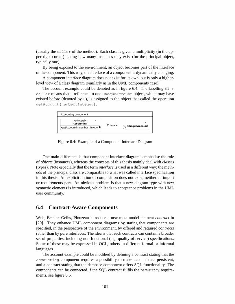
(usually thecaller of the method). Each class is given a multiplicity (in the up-per right corner) stating how many instances may exist (for the principal object,typically one).
By being exposed to the environment, an object becomes part of the interfaceof the component. This way, the interface of a component is dynamically changing.
A component interface diagram does not exist for its own, but is only a higher-level view of a class diagram (similarly as in the UML components case).
The account example could be denoted as in figure6.4. The labelling$1->
caller means that a reference to oneChequeAccount object, which may haveexisted before (denoted by$), is assigned to the object that called the operationgetAccount(number:Integer) .
* ChequeAccount
Accounting component
$1->caller +getAccount(in number : Integer)
«principal» Accounting
1
Figure 6.4:Example of a Component Interface Diagram
One main difference is that component interface diagrams emphasise the roleof objects(instances), whereas the concepts of this thesis mainly deal withclasses(types). Note especially that the terminterfaceis used in a different way; the meth-ods of the principal class are comparable to what was called interface specificationin this thesis. An explicit notion of composition does not exist, neither an importor requirements part. An obvious problem is that a new diagram type with newsyntactic elements is introduced, which leads to acceptance problems in the UMLuser community.
6.4 Contract-Aware Components
Weis, Becker, Geihs, Plouzeau introduce a new meta-model elementcontract in[29]. They enhance UML component diagrams by stating that components arespecified, in the perspective of the environment, by offered and requiredcontractsrather than by pure interfaces. The idea is that such contracts can contain a broaderset of properties, including non-functional (e.g. quality of service) specifications.Some of these may be expressed in OCL, others in different formal or informallanguages.
The account example could be modified by defining a contract stating that theAccounting component requires a possibility to make account data persistent,and a contract stating that the database component offers SQL functionality. Thecomponents can be connected if the SQL contract fulfils the persistency require-ments, see figure6.5.
101
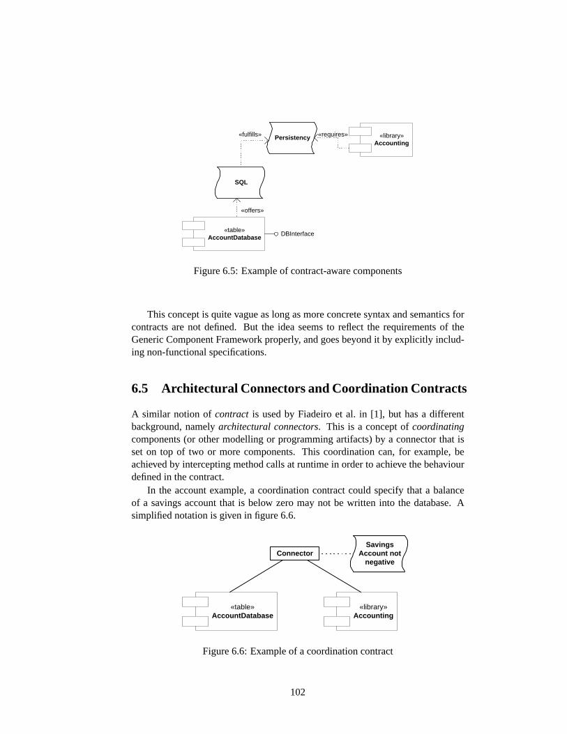
«table» AccountDatabase
«library» Accounting
DBInterface
Persistency
SQL
«fulfills»
«offers»
«requires»
Figure 6.5:Example of contract-aware components
This concept is quite vague as long as more concrete syntax and semantics forcontracts are not defined. But the idea seems to reflect the requirements of theGeneric Component Framework properly, and goes beyond it by explicitly includ-ing non-functional specifications.
6.5 Architectural Connectors and Coordination Contracts
A similar notion ofcontract is used by Fiadeiro et al. in [1], but has a differentbackground, namelyarchitectural connectors. This is a concept ofcoordinatingcomponents (or other modelling or programming artifacts) by a connector that isset on top of two or more components. This coordination can, for example, beachieved by intercepting method calls at runtime in order to achieve the behaviourdefined in the contract.
In the account example, a coordination contract could specify that a balanceof a savings account that is below zero may not be written into the database. Asimplified notation is given in figure6.6.
«table» AccountDatabase
«library» Accounting
Savings Account not
negative Connector
Figure 6.6:Example of a coordination contract
102
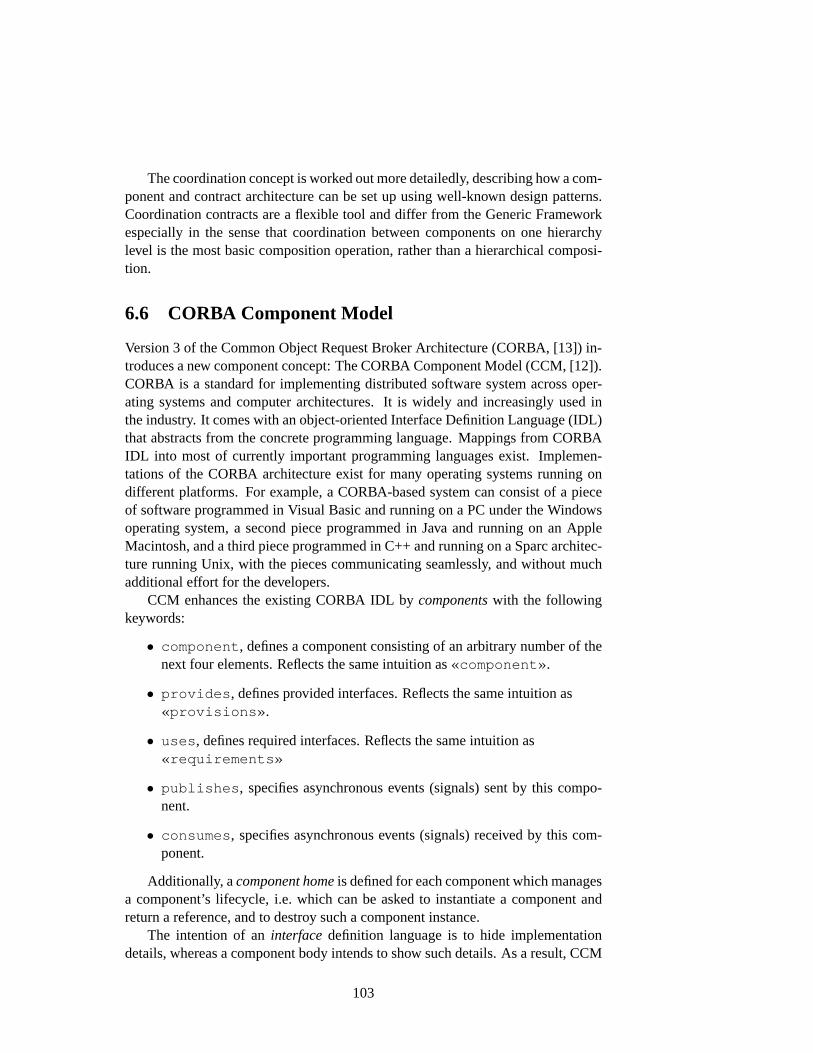
The coordination concept is worked out more detailedly, describing how a com-ponent and contract architecture can be set up using well-known design patterns.Coordination contracts are a flexible tool and differ from the Generic Frameworkespecially in the sense that coordination between components on one hierarchylevel is the most basic composition operation, rather than a hierarchical composi-tion.
6.6 CORBA Component Model
Version 3 of the Common Object Request Broker Architecture (CORBA, [13]) in-troduces a new component concept: The CORBA Component Model (CCM, [12]).CORBA is a standard for implementing distributed software system across oper-ating systems and computer architectures. It is widely and increasingly used inthe industry. It comes with an object-oriented Interface Definition Language (IDL)that abstracts from the concrete programming language. Mappings from CORBAIDL into most of currently important programming languages exist. Implemen-tations of the CORBA architecture exist for many operating systems running ondifferent platforms. For example, a CORBA-based system can consist of a pieceof software programmed in Visual Basic and running on a PC under the Windowsoperating system, a second piece programmed in Java and running on an AppleMacintosh, and a third piece programmed in C++ and running on a Sparc architec-ture running Unix, with the pieces communicating seamlessly, and without muchadditional effort for the developers.
CCM enhances the existing CORBA IDL bycomponentswith the followingkeywords:
• component , defines a component consisting of an arbitrary number of thenext four elements. Reflects the same intuition as«component» .
• provides , defines provided interfaces. Reflects the same intuition as«provisions» .
• uses , defines required interfaces. Reflects the same intuition as«requirements»
• publishes , specifies asynchronous events (signals) sent by this compo-nent.
• consumes , specifies asynchronous events (signals) received by this com-ponent.
Additionally, acomponent homeis defined for each component which managesa component’s lifecycle, i.e. which can be asked to instantiate a component andreturn a reference, and to destroy such a component instance.
The intention of aninterfacedefinition language is to hide implementationdetails, whereas a component body intends to show such details. As a result, CCM
103

software can most intuitively be modelled by component interface specifications asdefined in section2.5. Figure6.7shows an excerpt of the IOSIP model, figure6.8shows a possible mapping to CORBA IDL (without making use, for simplicity, ofthemodule keyword that defines namespaces).
«requirements» InterpreterReqNegotiation
«provisions» InterpreterPro
«component» Interpreter
«requirements» InterpreterReqStorage
+interpret(in msg : Message)
Interpreter
+allHAGVs() : Collection(ID)
Storage
«Signal»+processMachineState(in state : MachineState) «Signal»+processOffer(in o : Offer)
Negotiator
«Signal»+processMachineState(in state : MachineState) «Signal»+processOffer(in o : Offer)
Negotiator
«component» Negotiator
«provisions» NegotiatorPro
«component» Storage
«provisions» StoragePro
+allHAGVs() : Collection(ID)
Storage
«provide»
«provide»
Figure 6.7:An excerpt of the IOSIP model
The CCM specification goes beyond the pure IDL: it also defines how com-ponents are implemented, how they are deployed into acomponent container, andhow they are configured bydeployment descriptors. A component container is asoftware running on an application server that handles aspects the component de-veloper does not explicitly have to program but which are important in enterpriseand other high-quality software, such as security issues, persistency, transactionsafety, and distribution over multiple computers. A deployment descriptor is atext file that stores attributes and parameters of a component that can be changedwithout recompiling the component.
The CCM contains the same basic assumption about components as the GenericFramework, namely that they consist of provided and required interfaces and a hid-den part realising the provisions using the requirements. Therefore, a mapping ofthe UML component concept defined in this thesis to the CCM is possible. But thecomparison also shows that modern component technologies contain many fea-tures that are often not appropriately modelled in UML. It depends on project sizeand on the tools and methods used, in which phases of a development process it is
104

// basic typesinterface Message{
// ...};interface ID{
// ...};typedef sequence<ID> IDCollection;
// component interfacesinterface Interpreter{
void interpret( in Message m );};interface Storage{
IDCollection allHAGVs();};
// event typeseventtype MachineState{
// ...};eventtype Offer{
// ...};
// component typescomponent StorageComp{
provides Storage storage;};component InterpreterComp{
provides Interpreter interpreter;uses Storage storage;publishes MachineState state;publishes Offer offer;
};component NegotiatorComp{
consumes MachineState state;consumes Offer offer;
};
// component homeshome StorageHome manages StorageComp {};home InterpreterHome manages InterpreterComp {};home NegotiatorHome manages NegotiatorComp {};
Figure 6.8:CORBA 3 IDL for the IOSIP model
105
correct to ”abstract away” such implementation issues, and in which they have tobe taken into account. It is not useful to start modelling a system with all detailsof the target programming language in mind. But it is also dangerous to forgetall technological issues, because an un-implementable system could be modelledthen.
6.7 Conclusion
In this thesis it was analysed in how far the Generic Component Framework canbe instantiated by the UML. Existing UML model elements were discussed andenhanced by the UML extension mechanisms. The results are a UML profile forcomponent-based modelling, and a justification that models conforming to thisprofile can be viewed as instances of the Generic Framework.
A developer using the UML with this new constructs gains a concept for struc-turing large models that is at a higher level than the existing techniques. The mostimportant feature of components is the abstract import of services, resulting in atrue decoupling of components. This is a small step towards the ”Holy Grail” ofeffective reuseof software (which should include models, code, and other docu-mentation).
In some parts of the thesis the UML was used as if it were a formally definedspecification language, by using terms such as refinement transformation and in-clusion. But it has to be kept clearly in mind that the UML 1.4 lacks formalityand precision in many places. Not every aspect of the Generic Framework can bereflected easily in the UML. Even for the simpler case of class diagrams, problemshad to be solved that do not occur in other specification techniques, such as thenon-transitive import dependency, see section2.2.1.
The UML is a complex language; diagram elements of very different naturecan be combined almost arbitrarily in order to specify different views on a soft-ware system. This causes consistency problems in different dimensions: withinone diagram, between diagrams that represent different views of a model, betweendiagrams at different levels of abstraction, and between diagrams of a system evo-lution over time. At first sight, modelling a system with components solves noneof these problems, but rather introduces a new dimension of complexity. But whena complete and sufficiently formal concept of components and component compo-sition exists, some of the consistency checks have to be performed only on smallparts of the system, because the component framework ensures compositionality.Similar arguments hold for other kinds of property preservation. Possible furtherwork could include a concretisation of the refinement notions for class and state-chart diagrams, which are left very simple in this thesis.
While working on the UML component concept, it also became obvious thatthe Generic Component Framework is a quite weak construct as long as there areno restrictions on the transformations and inclusions other than the intuitive de-scriptions. The UML component concept was designed to fulfil these intuitions,
106
but lacks more precise properties as well as the abstract framework.If a formal semantics for the UML were defined, the results of this thesis could
be reformulated within that formal framework. This could result in a fully formalcomponent framework. But even on the non-formal level this thesis could be usedas a starting point for more concrete component concepts, especially by ”pluggingin” different notions of refinement that preserve important properties. The compo-nent concept as presented in this thesis ensures some basic syntactical consistency.One kind of formalisation of the UML useful in the context of components couldbe a categorical formalisation, maybe even a description of (a subset of) the UMLin terms of High-Level Replacement categories.
An interesting formalisation of refinement of classes by predicate transformersemantics, and a corresponding refinement calculus are introduced in [21].
Besides reuse, another aim of decomposing a system into self-contained partsis the ability to perform various checks and proofs of properties on the model.The ability to formally prove properties of a model is the key advantage of formalmodelling techniques. But also with the UML precise modelling is possible. Thisthesis uses some features of the UML that are not often used, such as a profiledefinition using OCL, but deliver very precise models. In software developmentpractice, the UML is most often not used with the maximum precision it offers.This becomes obvious, for example, when looking at the UML modelling tools onthe market which usually can generate program code from class diagrams withoutregarding OCL or behavioural specifications (that is, classes and empty method’stubs’). The developers use only informal specifications and class diagrams asa design model, and implement all behaviour directly in program code. This isappropriate in many practical situations, but does not allow for modern softwareengineering analysis techniques such as model checking or theorem proving, whichare essential in the development of high quality (e.g. safety-critical) software.
The concepts defined in this thesis should, of course, be proven to be usefulin practice. The techniques used to define the component concept conform to theUML 1.4 specification, and thus allow to use existing modelling tools. The newstereotypes, constrained by OCL, could be added to a tool’s set of modelling ele-ments. Unfortunately, most UML modelling tools do either lack the possibility toadd profiles and stereotypes, or are not able to evaluate OCL, or have a different(proprietary) means to add profiles. In order to make the new stereotypes moreusable, new visual notations could additionally be defined.
Acknowledgements
This work is partially supported by the DFG within the research project IOSIP,which is part of the DFG priority program ”Integration of Software SpecificationTechniques for Applications in Engineering”.
I would like to thank Hartmut Ehrig, Benjamin Braatz, Markus Klein andMesut Özhan for valuable comments and constructive discussions on the topicsof this thesis.
107
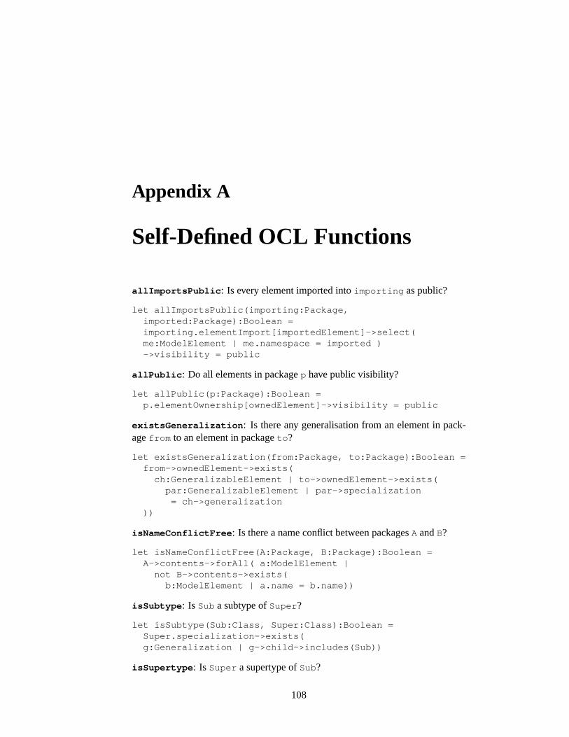
Appendix A
Self-Defined OCL Functions
allImportsPublic : Is every element imported intoimporting as public?
let allImportsPublic(importing:Package,imported:Package):Boolean =importing.elementImport[importedElement]->select(me:ModelElement | me.namespace = imported )->visibility = public
allPublic : Do all elements in packagep have public visibility?
let allPublic(p:Package):Boolean =p.elementOwnership[ownedElement]->visibility = public
existsGeneralization : Is there any generalisation from an element in pack-agefrom to an element in packageto ?
let existsGeneralization(from:Package, to:Package):Boolean =from->ownedElement->exists(
ch:GeneralizableElement | to->ownedElement->exists(par:GeneralizableElement | par->specialization
= ch->generalization))
isNameConflictFree : Is there a name conflict between packagesA andB?
let isNameConflictFree(A:Package, B:Package):Boolean =A->contents->forAll( a:ModelElement |
not B->contents->exists(b:ModelElement | a.name = b.name))
isSubtype : Is Sub a subtype ofSuper ?
let isSubtype(Sub:Class, Super:Class):Boolean =Super.specialization->exists(g:Generalization | g->child->includes(Sub))
isSupertype : Is Super a supertype ofSub?
108
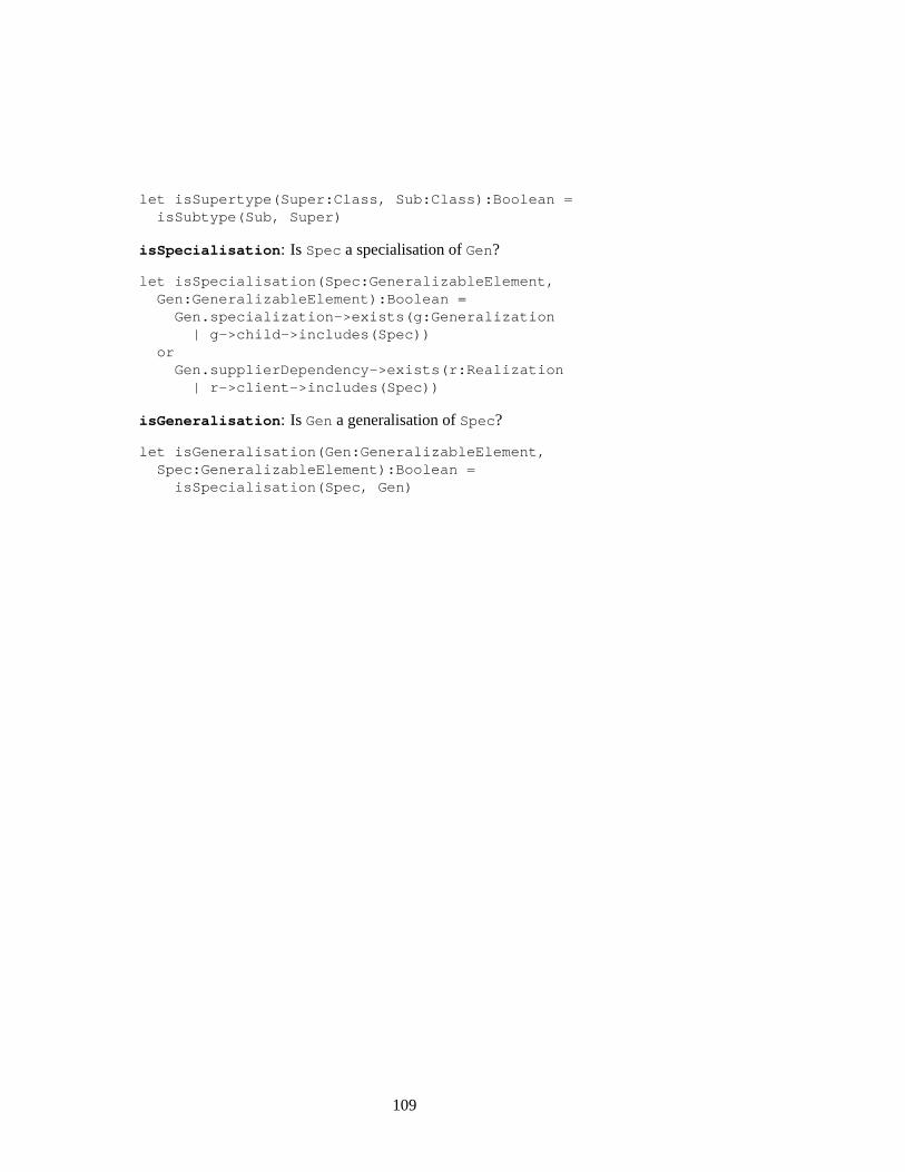
let isSupertype(Super:Class, Sub:Class):Boolean =isSubtype(Sub, Super)
isSpecialisation : Is Spec a specialisation ofGen?
let isSpecialisation(Spec:GeneralizableElement,Gen:GeneralizableElement):Boolean =
Gen.specialization->exists(g:Generalization| g->child->includes(Spec))
orGen.supplierDependency->exists(r:Realization
| r->client->includes(Spec))
isGeneralisation : Is Gen a generalisation ofSpec?
let isGeneralisation(Gen:GeneralizableElement,Spec:GeneralizableElement):Boolean =
isSpecialisation(Spec, Gen)
109
Bibliography
[1] Luís Filipe Andrade and José Luiz Fiadeiro. Contracts: Supportingarchitecture-based evolution. submitted.www.fiadeiro.org/jose/papers/ .
[2] Dave Astels. Refactoring with UML. InProc. 3rd International Conferenceon eXtreme Programming and Flexible Processes in Software Engineering(XP2002), 2002.www.xp2002.org/prog_full.html .
[3] Arnulf Braatz and Arno Ritter. Referenzfallstudie Produktionstechnik Ver-sion 2.0, 2001.tfs.cs.tu-berlin.de/projekte/indspec/SPP/themenbereiche.html .
[4] John Cheesman and John Daniels.UML Components. Addison-Wesley,2001.
[5] Desmond D’Souza and Alan Wills.Objects, Components and FrameworksWith UML: The Catalysis Approach. Addison-Wesley, 1998.
[6] Jürgen Ebert and Gregor Engels. Specialization of object life cycle defini-tions. Fachbericht Informatik 19/95, Universität Koblenz-Landau, Fachbere-ich Informatik, 1995.
[7] Hartmut Ehrig, Robert Geisler, Marcus Klar, and Julia Padberg. Horizontaland Vertical Structuring Techniques for Statecharts. In A. Mazurkiewicz andJ. Winkowski, editors,LNCS Vol. 1243, CONCUR’97: Concurrency Theory,8th International Conference, Warsaw, Poland, pages 181–195. Springer Ver-lag, 1997.
[8] Hartmut Ehrig and Bernd Mahr.Fundamentals of Algebraic Specification 2:Module Specifications and Constraints. Springer, Berlin, 1990.
[9] Hartmut Ehrig, Fernando Orejas, Benjamin Braatz, Markus Klein, and MarttiPiirainen. A Generic Component Concept for System Modeling. InProc.FASE 2002: Formal Aspects of Software Engineering, 2002.
[10] Hartmut Ehrig, Fernando Orejas, Benjamin Braatz, Markus Klein, and MarttiPiirainen. A Component Framework Based on High-Level Replacement Sys-
110
tems. InProc. International Workshop on Graph Transformation and VisualModeling Techniques, 2002.
[11] Gregor Engels, Reiko Heckel, and Jochen Malte Küster. Rule-Based Speci-fication of Behavioral Consistency Based on the UML Meta-model. InProc.UML 2001: Formal Aspects of Software Engineering, volume 2185 ofLec-ture Notes in Computer Science, pages 272–286. Springer-Verlag, 2001.
[12] Object Management Group. Common object request broker architecture:Component model specification (version 3.0). Technical Report formal/2002-06-65, Object Management Group, 2002.www.omg.org/cgi-bin/doc?formal/02-06-65 .
[13] Object Management Group. Common object request broker architecture:Core specification (version 3.0). Technical Report formal/2002-12-06, ObjectManagement Group, 2002.www.omg.org/cgi-bin/doc?formal/02-12-06 .
[14] Object Management Group. UML profile for CORBA specification (version1.0). Technical Report formal/02-04-01, Object Management Group, 2002.www.omg.org/cgi-bin/doc?formal/02-04-01 .
[15] Object Management Group. XML metadata interchange (XMI) specification(version 1.2). Technical Report formal/02-01-01, Object Management Group,2002.www.omg.org/cgi-bin/doc?formal/02-01-01 .
[16] Franz Huber, Andreas Rausch, and Bernhard Rumpe. Component interfacediagrams: Putting components to work. Technical Report TUM-I9831, Tech-nische Univerität München, 1998.
[17] Franz Huber, Andreas Rausch, and Bernhard Rumpe. Modeling dynamiccomponent interfaces. In Madhu Singh, Bertrand Meyer, Joseph Gil, andRichard Mitchell, editors,Technology of Object-Oriented Languages andSystems (TOOLS 26). IEEE Computer Society, 1998.
[18] Markus Klein, Mesut Özhan, and Martti Piirainen. Agent-based mate-rial flow. In Reiko Heckel, Tom Mens, and Michel Wermelinger, editors,Proc. Workshop on Software Evolution Through Transformations, volume 72.Elsevier Science Publishers, 2002.
[19] Stefan Mann, Alexander Borusan, Hartmut Ehrig, Martin Große-Rhode,Rainer Mackenthun, Asuman Sünbül, and Herbert Weber. Towards a compo-nent concept for continuous software engineering. Technical Report 55/00,Fraunhofer Institute for Software and Systems Engineering, 2000.
[20] Bertrand Meyer. Applying ”Design by Contract”. IEEE Computer,25(10):40–51, October 1992.
111
[21] Anna Mikhajlova and Emil Sekerinski. Class refinement and interface re-finement in object-oriented programs. In John Fitzgerald, Cliff B. Jones, andPeter Lucas, editors,Proc. FME’97, volume 1313 ofLecture Notes in Com-puter Science, pages 82–101. Springer-Verlag, 1997.
[22] Julia Padberg, Herbert Weber, and Asuman Sünbül. Petri net based compo-nents for evolvable architectures. InTransactions of the SDPS, volume 6(1).Society for Design and Process Science, 2002.
[23] Bernhard Rumpe, M. Schoenmakers, A. Radermacher, and Andy Schürr.UML + ROOM as a standard ADL? InProc. ICECCS’99 Fifth IEEE In-ternational Conference on Engineering of Complex Computer Systems, 1999.
[24] Enterprise JavaBeans specification (version 2.0). Technical report, Sun Mi-crosystems, 2001.java.sun.com/products/ejb/docs.html .
[25] Gabriele Taentzer. A visual modeling framework for distributed object com-puting. In Bart Jacobs and Arend Rensink, editors,Formal methods for openobject-based distributed systems, volume V. Kluwer Academic Publishers,2002.
[26] Jennifer Tenzer and Perdita Stevens. Modelling recursive calls with UMLstate diagrams. To appear in Proc. FASE 2003.
[27] Laurence Tratt, Tony Clark, and Andy Evans. Modelling generalization andother class-to-parent relationships. Technical Report TR-02-05, Departmentof Computer Science, King’s College London, July 2002.
[28] UML Revision Taskforce. OMG Unified Modeling Language Specifica-tion (version 1.4). Technical Report formal/2001-09-67, Object ManagementGroup, 2001.www.omg.org/cgi-bin/doc?formal/01-09-67 .
[29] Torben Weis, Christian Becker, Kurt Geihs, and Noël Plouzeau. A UMLmeta-model for contract aware components.Lecture Notes in Computer Sci-ence, 2185:442–456, 2001.
112