AspectsofCodeGenerationand DataTransferTechniquesfor ... · zur Erlangung des akademischen Grades...
344
Aspects of Code Generation and Data Transfer Techniques for Modern Parallel Architectures zur Erlangung des akademischen Grades eines Doktors der Ingenieurwissenschaften / Doktors der Naturwissenschaften der KIT-Fakultät für Informatik des Karlsruher Instituts für Technologie (KIT) vorgelegte Dissertation von Manuel Mohr aus Heilbronn Tag der mündlichen Prüfung: tbd Erster Gutachter: Prof. Dr.-Ing. Gregor Snelting Zweiter Gutachter: Prof. Dr.-Ing. Jürgen Teich Dritter Gutachter: Prof. Dr. rer. nat. Sebastian Hack
Transcript of AspectsofCodeGenerationand DataTransferTechniquesfor ... · zur Erlangung des akademischen Grades...
Aspects of Code Generation andData Transfer Techniques forModern Parallel Architectures
zur Erlangung des akademischen Grades eines
Doktors der Ingenieurwissenschaften /Doktors der Naturwissenschaften
der KIT-Fakultät für Informatikdes Karlsruher Instituts für Technologie (KIT)
vorgelegteDissertation
von
Manuel Mohr
aus Heilbronn
Tag der mündlichen Prüfung: tbd
Erster Gutachter: Prof. Dr.-Ing. Gregor Snelting
Zweiter Gutachter: Prof. Dr.-Ing. Jürgen Teich
Dritter Gutachter: Prof. Dr. rer. nat. Sebastian Hack

Eidesstattliche Erklärung
Hiermit erkläre ich an Eides statt, die vorliegende Dissertation selbststän-dig und nur unter Zuhilfenahme der ausgewiesenen Hilfsmittel angefertigtzu haben. Sämtliche Stellen der Arbeit, die im Wortlaut oder dem Sinnnach anderen gedruckten oder im Internet verfügbaren Werken entnom-men sind, habe ich durch genaue Quellenangaben kenntlich gemacht.Ich erkläre außerdem, dass die Dissertation weder in gleicher noch inähnlicher Form bereits in einem anderen Prüfungsverfahren vorgelegenhat.
Karlsruhe, den 14. Dezember 2017
Manuel Mohr
Affidavit
I hereby confirm that the dissertation at hand is the result of my own work.All used or quoted sources and materials are listed and specified in thedissertation. Furthermore, I confirm that this dissertation has not yet beensubmitted as part of another examination process neither in identical norin similar form.
Karlsruhe, December 14, 2017
Manuel Mohr

Contents
Contents v
1. Introduction 1
1.1. Contributions . . . . . . . . . . . . . . . . . . . . . . . . . . 6
1.2. Structure . . . . . . . . . . . . . . . . . . . . . . . . . . . . . 9
1.3. Notation and Conventions . . . . . . . . . . . . . . . . . . . 10
1.4. List of Publications . . . . . . . . . . . . . . . . . . . . . . . 10
2. Non-Cache-Coherent Architectures 13
2.1. A Taxonomy of Parallel Architectures . . . . . . . . . . . . 13
2.1.1. Memory Organization . . . . . . . . . . . . . . . . . 14
2.1.2. Communication Model . . . . . . . . . . . . . . . . 14
2.1.3. Typical Combinations . . . . . . . . . . . . . . . . . 16
vi Contents
2.2. Cache Coherence . . . . . . . . . . . . . . . . . . . . . . . . 17
2.2.1. Separating Coherence from Consistency . . . . . . . 19
2.2.2. Implementation . . . . . . . . . . . . . . . . . . . . . 21
2.3. Hardware Architecture . . . . . . . . . . . . . . . . . . . . . 30
2.3.1. Examples of Non-Cache-Coherent Architectures . . 33
2.4. Programming Model . . . . . . . . . . . . . . . . . . . . . . 40
2.4.1. Parallel Programming Models . . . . . . . . . . . . 41
2.4.2. Shared-Memory Programming Model . . . . . . . . 43
2.4.3. Message Passing . . . . . . . . . . . . . . . . . . . . 49
2.4.4. The PGAS Model . . . . . . . . . . . . . . . . . . . . 53
3. Invasive Computing 57
3.1. The Invasive Paradigm . . . . . . . . . . . . . . . . . . . . . 58
3.2. Hardware Architecture . . . . . . . . . . . . . . . . . . . . . 60
3.2.1. Related Work . . . . . . . . . . . . . . . . . . . . . . 62
3.3. Operating System . . . . . . . . . . . . . . . . . . . . . . . . 63
3.3.1. Related Work . . . . . . . . . . . . . . . . . . . . . . 66
3.4. Programming Language . . . . . . . . . . . . . . . . . . . . 68
3.4.1. Shared-Memory Parallelism . . . . . . . . . . . . . . 70
3.4.2. Distributed-Memory Parallelism . . . . . . . . . . . 72
3.4.3. Related Work . . . . . . . . . . . . . . . . . . . . . . 74
3.5. Compiler . . . . . . . . . . . . . . . . . . . . . . . . . . . . . 75
3.5.1. Compilation of Generic Classes and Methods . . . . 76
3.5.2. Handling of Native Methods . . . . . . . . . . . . . 78
3.6. Hardware Prototype . . . . . . . . . . . . . . . . . . . . . . 80
Contents vii
4. Compiling X10 to Invasive Architectures 83
4.1. Intra-Tile Parallelism . . . . . . . . . . . . . . . . . . . . . . 86
4.2. Inter-Tile Parallelism . . . . . . . . . . . . . . . . . . . . . . 89
4.3. Block-Based Data Transfers . . . . . . . . . . . . . . . . . . 91
4.3.1. Using TLM . . . . . . . . . . . . . . . . . . . . . . . 93
4.3.2. Using Off-Chip Memory . . . . . . . . . . . . . . . . 97
4.3.3. Related Work . . . . . . . . . . . . . . . . . . . . . . 99
4.3.4. Implementation on the Hardware Prototype . . . . 101
4.4. Transferring Pointered Data Structures . . . . . . . . . . . . 108
4.4.1. Serialization-Based Approaches . . . . . . . . . . . 114
4.4.2. Cloning-Based Approaches . . . . . . . . . . . . . . 117
4.4.3. Related Work . . . . . . . . . . . . . . . . . . . . . . 122
4.4.4. Implementation on the Hardware Prototype . . . . 125
4.5. Hardware Support . . . . . . . . . . . . . . . . . . . . . . . 128
4.5.1. Design Space . . . . . . . . . . . . . . . . . . . . . . 129
4.5.2. Concept and Implementation . . . . . . . . . . . . . 131
4.5.3. Related Work . . . . . . . . . . . . . . . . . . . . . . 134
4.6. Evaluation . . . . . . . . . . . . . . . . . . . . . . . . . . . . 135
4.6.1. Setup . . . . . . . . . . . . . . . . . . . . . . . . . . . 135
4.6.2. Establishing an Evaluation Environment . . . . . . 137
4.6.3. Block-Based Data Transfers . . . . . . . . . . . . . . 140
4.6.4. Transfers of Pointered Data Structures . . . . . . . . 142
4.6.5. Hardware Overhead . . . . . . . . . . . . . . . . . . 159
4.6.6. Threats to Validity . . . . . . . . . . . . . . . . . . . 162
4.7. Relation to Invasive X10 . . . . . . . . . . . . . . . . . . . . 164
viii Contents
5. Code Generation with Permutation Instructions 171
5.1. Introduction . . . . . . . . . . . . . . . . . . . . . . . . . . . 176
5.1.1. Parallel Copies and Register Transfer Graphs . . . . 176
5.1.2. Permutation Instructions . . . . . . . . . . . . . . . 182
5.2. Hardware Implementation . . . . . . . . . . . . . . . . . . . 187
5.2.1. Fundamental Pipeline Modifications . . . . . . . . . 187
5.2.2. Exception Handling . . . . . . . . . . . . . . . . . . 191
5.3. Code Generation . . . . . . . . . . . . . . . . . . . . . . . . 194
5.3.1. Implementing RTGs on Regular Machines . . . . . 195
5.3.2. Reformulation as a Graph Problem . . . . . . . . . . 198
5.3.3. Optimal Shuffle Code for Outdegree-1 RTGs . . . . 204
5.3.4. A Heuristic for Finding Copy Sets . . . . . . . . . . 214
5.3.5. Finding Optimal Copy Sets . . . . . . . . . . . . . . 218
5.3.6. Related Work . . . . . . . . . . . . . . . . . . . . . . 232
5.4. Evaluation . . . . . . . . . . . . . . . . . . . . . . . . . . . . 234
5.4.1. Setup . . . . . . . . . . . . . . . . . . . . . . . . . . . 234
5.4.2. Register-Transfer-Graph Properties . . . . . . . . . . 237
5.4.3. Heuristic and Optimal Code Generation . . . . . . . 238
5.4.4. Compilation Time . . . . . . . . . . . . . . . . . . . 240
5.4.5. Code Quality . . . . . . . . . . . . . . . . . . . . . . 242
5.4.6. Hardware Overhead . . . . . . . . . . . . . . . . . . 250
5.4.7. Threats to Validity . . . . . . . . . . . . . . . . . . . 252
5.5. Generalization . . . . . . . . . . . . . . . . . . . . . . . . . . 255
5.5.1. Out-of-Order Execution . . . . . . . . . . . . . . . . 255
5.5.2. Implementing Permutation Instructions . . . . . . . 258
Contents ix
6. Conclusion and Future Work 263
A. Appendix 269
A.1. Recommendations for Invasive Architectures . . . . . . . . 269
A.2. The Intermediate Representation Firm . . . . . . . . . . . . 271
A.3. k-Shuffle Code Generation is NP-complete . . . . . . . . . . 274
A.3.1. Complexity . . . . . . . . . . . . . . . . . . . . . . . 274
A.3.2. Approximation Algorithm . . . . . . . . . . . . . . . 275
B. Software Artifacts 277
C. Curriculum Vitae 279
List of Figures 281
List of Tables 287
Index 319

Prose is architecture and the Baroque age is over.
Ernest Hemingway
Abstract
The focus of hardware architecture development has shifted from strivingfor ever higher clock frequencies towards incorporating an ever increasingnumber of cores on a single chip. A high number of cores makes itpossible to offer a mixture of weak and strong cores, and even specializedcores with completely different instruction sets. This makes developmentfor such a heterogeneous platform challenging and requires adequatesupport by tools, such as compilers. Besides their core structure, thereis a second dimension to these architectures: memory. A major obstacleto scalability regarding the memory hierarchy of many-core platformsis maintaining global cache coherence. Hardware coherence protocolseither scale poorly, or are complex and often suffer from performance andpower overheads. Abandoning global cache coherence is a radical solutionto this problem. However, efficiently mapping programming models tohardware with relaxed guarantees is challenging. In this dissertation, wemake contributions to compilation techniques targeting both dimensionsof modern parallel architectures: memory and core structure.
The first part of this dissertation concerns data transfer techniques for non-cache-coherent architectures. Such non-cache-coherent shared-memory
xi
xii Contents
architectures provide a shared physical address space, but do not im-plement hardware-based coherence between all caches of the system.Logically partitioning the shared memory offers a safe way of program-ming such a platform. In general, this creates the need to copy databetween memory partitions.
We study the compilation to invasive architectures, a family of non-cache-coherent many-core architectures. We investigate the efficient implementa-tion of data transfers for both simple and complex data structures on thesearchitectures. Specifically, we propose a novel approach to copy complexpointered data structures without the need for serialization. To this end,we generalize object cloning to work in the presence of non-coherentcaches by extending object cloning with compiler-directed automaticsoftware-managed coherence. We present implementations of multipledata transfer techniques in an existing compiler and runtime system. Weextensively evaluate these implementations on an FPGA-based prototypeof an invasive architecture. Finally, we propose adding hardware supportfor range-based cache operations, and describe and evaluate possibleimplementations and overheads.
The second part of this dissertation concerns code generation techniquesto accelerate shuffle code by using permutation instructions. Shufflecode arises during register allocation, where the compiler maps programvariables to machine registers. The compiler may introduce shuffle code,consisting of copy and swap operations, to transfer data between registers.Depending on the quality of register allocation and the number of availableregisters, a large amount of shuffle code may be generated.
We propose to speed up the execution of shuffle code by using permutationinstructions that arbitrarily permute the contents of small sets of registersin one clock cycle. To show the feasibility of this idea we first present anextension of an existing RISC instruction set with permutation instructions.We then describe how to implement the proposed permutation instructionsin an existing RISC architecture. Subsequently, we develop two codegeneration schemes that exploit permutation instructions to implementshuffle code: a fast heuristic and a dynamic-programming-based approach.We formally prove quality and correctness properties of both approachesand show the latter approach to be optimal. In the following, we implementboth code generation algorithms in a compiler and extensively evaluate
Contents xiii
and compare their code quality using a standardized benchmark suite. Wefirst measure precise dynamic instruction counts, which we then validateby measuring running times on an FPGA-based prototype implementationof the proposed RISC architecture with permutation instructions. Finally,we argue that permutation instructions are cheap to implement on modernout-of-order architectures that already support register renaming.

Optimierung ist, wenn es
manchmal nicht schlechter wird.
Lehrstuhlweisheit, nach Rubino Geiß
Zusammenfassung
Im Bereich der Prozessorarchitekturen hat sich der Fokus neuer Entwick-lungen von immer höheren Taktfrequenzen hin zu immer mehr Kernenauf einem Chip verschoben. Eine hohe Kernanzahl ermöglicht es unter-schiedlich leistungsfähige Kerne anzubieten, und sogar dedizierte Kernemit speziellen Befehlssätzen. Die Entwicklung für solch heterogene Platt-formen ist herausfordernd und benötigt entsprechende Unterstützung vonEntwicklungswerkzeugen, wie beispielsweise Übersetzern. Neben ihrerheterogenen Kernstruktur gibt es eine zweite Dimension, die die Entwick-lung für solche Architekturen anspruchsvoll macht: ihre Speicherstruktur.Die Aufrechterhaltung von globaler Cache-Kohärenz erschwert das Errei-chen hoher Kernzahlen. Hardwarebasierte Cache-Kohärenz-Protokolleskalieren entweder schlecht, oder sind kompliziert und führen zu Pro-blemen bei Ausführungszeit und Energieeffizienz. Eine radikale Lösungdieses Problems stellt die Abschaffung der globalen Cache-Kohärenz dar.Jedoch ist es schwierig, bestehende Programmiermodelle effizient aufsolch eine Hardware-Architektur mit schwachen Garantien abzubilden.
Der erste Teil dieser Dissertation beschäftigt sich Datentransfertechni-ken für nicht-cache-kohärente Architekturen mit gemeinsamem Speicher.
xv
xvi Contents
Diese Architekturen bieten einen gemeinsamen physikalischen Adress-raum, implementieren aber keine hardwarebasierte Kohärenz zwischenallen Caches des Systems. Die logische Partitionierung des gemeinsamenSpeichers ermöglicht die sichere Programmierung einer solchen Platt-form. Im Allgemeinen erzeugt dies die Notwendigkeit Daten zwischenSpeicherpartitionen zu kopieren.
Wir untersuchen die Übersetzung für invasive Architekturen, einer Familievon nicht-cache-kohärenten Vielkernarchitekturen. Wir betrachten dieeffiziente Implementierung von Datentransfers sowohl einfacher als auchkomplexer Datenstrukturen auf invasiven Architekturen. Insbesondereschlagen wir eine neuartige Technik zum Kopieren komplexer verzei-gerter Datenstrukturen vor, die ohne Serialisierung auskommt. Hierzuverallgemeinern wir den Objekt-Klon-Ansatz mit übersetzergesteuerterautomatischer software-basierter Kohärenz, sodass er auch im Kontextnicht-kohärenter Caches funktioniert. Wir präsentieren Implementierun-gen mehrerer Datentransfertechniken im Rahmen eines existierendenÜbersetzers und seines Laufzeitsystems. Wir führen eine ausführlicheAuswertung dieser Implementierungen auf einem FPGA-basierten Pro-totypen einer invasiven Architektur durch. Schließlich schlagen wir vor,Hardwareunterstützung für bereichsbasierte Cache-Operationen hinzu-zufügen und beschreiben und bewerten mögliche Implementierungenund deren Kosten.
Der zweite Teil dieser Dissertation befasst sich mit der Beschleunigung vonShuffle-Code, der bei der Registerzuteilung auftritt, durch die Verwendungvon Permutationsbefehlen. Die Aufgabe der Registerzuteilung währendder Programmübersetzung ist die Abbildung von Programmvariablen aufMaschinenregister. Während der Registerzuteilung erzeugt der ÜbersetzerShuffle-Code, der aus Kopier- und Tauschbefehlen besteht, um Wertezwischen Registern zu transferieren. Abhängig von der Qualität derRegisterzuteilung und der Zahl der verfügbaren Register kann eine großeMenge an Shuffle-Code erzeugt werden.
Wir schlagen vor, die Ausführung von Shuffle-Code mit Hilfe von neuarti-gen Permutationsbefehlen zu beschleunigen, die die Inhalte von einigenRegistern in einem Taktzyklus beliebig permutieren. Um die Machbarkeitdieser Idee zu demonstrieren, erweitern wir zunächst ein bestehendesRISC-Befehlsformat um Permutationsbefehle. Anschließend beschreiben
Contents xvii
wir, wie die vorgeschlagenen Permutationsbefehle in einer bestehendenRISC-Architektur implementiert werden können. Dann entwickeln wirzwei Verfahren zur Codeerzeugung, die die Permutationsbefehle aus-nutzen, um Shuffle-Code zu beschleunigen: eine schnelle Heuristik undeinen auf dynamischer Programmierung basierenden optimalen Ansatz.Wir beweisen Qualitäts- und Korrektheitseingeschaften beider Ansätzeund zeigen die Optimalität des zweiten Ansatzes. Im Folgenden imple-mentieren wir beide Codeerzeugungsverfahren in einem Übersetzer unduntersuchen sowie vergleichen deren Codequalität ausführlich mit Hilfestandardisierter Benchmarks. Zunächst messen wir die genaue Zahl derdynamisch ausgeführten Befehle, welche wir folgend validieren, indemwir Programmlaufzeiten auf einer FPGA-basierten Prototypimplementie-rung der um Permutationsbefehle erweiterten RISC-Architektur messen.Schließlich argumentieren wir, dass Permutationsbefehle auf modernenOut-Of-Order-Prozessorarchitekturen, die bereits Registerumbenennungunterstützen, mit wenig Aufwand implementierbar sind.

Hofstadter’s Law: It always takes longer than you expect,
even when you take into account Hofstadter’s Law.
Douglas Hofstadter
Acknowledgments
First, I wish to thank my advisor Prof. Gregor Snelting for his supportand the opportunity to pursue my own interests without pressure. Ialso thank him for shielding me and his whole group from the manyadversities of academic life, such as the need to secure a steady stream ofmoney. He provided an environment where it was possible to concentrateon research, on building efficient and robust software, as well as onexcellence in teaching, which is a luxury one becomes accustomed to fartoo easily. Next, I would like to thank Prof. Jürgen Teich for reviewing thisdissertation. I also thank him for founding the research project InvasiveComputing, which taught me a great deal about hardware, software,the many things that can go wrong between them—and how great it iswhen they finally work together. The first part of this dissertation wouldnot have been possible without this research project. Moreover, I wantto thank Prof. Sebastian Hack for serving as the third reviewer of thisdissertation. I also thank him for leaving an inconspicuous footnote in hisdissertation, which ultimately gave rise to the second part of this work.
Next, I have to thank the (former and current) machine code connoisseursfrom the compiler group in Karlsruhe, namely Matthias Braun, Sebastian
xix
xx Contents
Buchwald, Andreas Fried, and Andreas Zwinkau. I especially thank myformer office inmate Matthias Braun for being a walking encyclopediaof Firm and x86 peculiarities and for sharing his knowledge with me.Furthermore, I thank Sebastian Buchwald for his tireless commitment tocorrectness and clarity of expression in both code and written text. Andalso for removing all trailing whitespace1. I thank Andreas Zwinkau forjoining me in the quest to bring the invasive prototype system to life whileat the same time keeping me up to date on every development in theworld of programming languages. Lastly, I thank Andreas Fried for beinga very knowledgable office mate, and for creating the nerdiest and mostdifficult crossword puzzle I ever failed to solve. All compiler constructorswere always available for help and technical discussions. Without them,countless hours of staring at Firm graphs and assembly dumps wouldhave been much more boring.
However, our group consisted of more than the pointer arithmeticians inthe compiler group. Thus, I also thank all my context-sensitive colleaguesfrom the JOANA group, namely Simon Bischof, Jürgen Graf, MartinHecker, and Martin Mohr. In particular, I thank Simon Bischof for findingan embarrassing number of bugs in our compiler lab reference compiler. Ithank Jürgen Graf for annual barbecues on his panorama terrace and beinga close (pun intended) friend. I thank Martin Hecker for his dedication toimproving the quality of our teaching material and for regularly destroyinghalf-baked or unfair exam question proposals. And I thank Martin Mohrfor his quirky humorous remarks and his love for everything at the bottomof the movie barrel. May all your wishes happen in parallel.
Moreover, I thank all side-effect-free purists from our automated theoremproving group, namely Joachim Breitner, Andreas Lochbihler, DenisLohner, Sebastian Ullrich, and Maximilian Wagner. I thank JoachimBreitner for producing new ideas faster than I could follow the previousones, and for proving that days do have more than 24 hours for somepeople. I thank “Altgesell” Andreas Lochbihler for taking me under hiswing back when I started as a doctoral researcher, and also for letting allour dissertations seem short in comparison. I thank Denis Lohner for hisoutstanding organizational skills and for his arcane knowledge of AFS andother technological oddities in our infrastructure. Lastly, I thank Sebastian
1I broke one ligature in this section on purpose, did you spot it?
Contents xxi
Ullrich and Maximilian Wagner for humiliating us and our compiler labreference compiler in front of everyone, and for convincing me that it ispossible to write beautiful Scala code.
Technically, I ought to mention everyone I met via the Invasive Computingproject, but this list would be too long. Hence, I have to pick some subsetand apologize in advance to everyone I do not mention. Thanks to theoperating systems group in Erlangen, namely Gabor Drescher, ChristophErhardt, Sebastian Maier, Benjamin Oechslein, Jens Schedel, and FlorianSchmaus for joining us in valiantly defending the system-software layeragainst evil feature-request deniers from the hardware down below andagainst blissfully ignorant application developers from above. ProjectC1 set the bar high for system software quality, just like it should be. Ialso thank Lars Bauer and Artjom Grudnitsky for realizing the slightlycrazy register permutation idea and answering all my stupid questionsabout hardware. And I thank Stephanie Friederich, Jan Heißwolf, SvenRheindt, and Aurang Zaib for bringing our hardware platform to life.Special thanks go to Sven Rheindt, who exhumed an ancient hardwaredesign from its grave in a decommissioned Subversion repository andadded some new functionality to it, just so I could improve my evaluation.Without people like the ones I just mentioned, who went the extra mileand sometimes traded fewer publications for more fixed bugs, the InvasiveComputing project would not have come as far as it did. They all madethe countless hours of fighting Scheinzwerge and Heisenbugs much moreworthwhile.
Furthermore, I thank Carsten Tradowsky for throwing student afterstudent at our project of extending hardware with range-based cacheoperations. He mastered the art of delegating tasks.
I thank Ignaz Rutter for his tremendous help with formalizing andinvestigating the theoretical aspects of shuffle-code generation. Back inMay 2012, I innocently walked into his office with my little problem ofgenerating shuffle code, expecting him to point me to some existing paperor book chapter. Somehow, a few months later, I had pages and pages oflemmas and proofs, and also quite some trouble still recognizing my ownproblem. It was a pleasure witnessing him working his magic while beingable to contribute a bit of my own. I also thank him for initiating weeklyRicochet Robots rounds years ago.
xxii Contents
Of course, I must mention all students who contributed to software orhardware projects that I used. One of the luxuries of working at a universityis the large pool of talented and highly motivated students I could drawfrom. Hence, I thank Eduard Frank, Jonas Haag, Christoph Jost, TobiasKahlert, Tobias Modschiedler, Julian Oppermann, Tobias Rapp, BernhardScheirle, Martin Seidel, and Philipp Serrer for their contributions.
I also thank all hard-working proof readers, who ploughed throughhundreds of pages and found issues both small and large. Namelymy helpers were Sebastian Buchwald, Christoph Erhardt, Andreas Fried,Marina Mohr, Martin Mohr, Maximilian Wagner, and Andreas Zwinkau.
Moreover, I thank my parents as well as my sister Marina for theirunconditional support of whatever decision I made and whatever task Iset my mind on. They always encouraged me to pursue my interests andnot to be afraid of taking on challenges. I especially thank my father fordenying me my wish for a VTech learning computer and instead putting areal PC into my room; something I assume very few nine year olds had atthat time. This sparked my interest in computers and programming and Ibenefit from this decision to this day.
Finally, I thank Eva for supporting and enduring me during the past years.In her, I have always found both an attentive listener as well as a keenobserver. I highly value her advice, as she is right more often than Ilike to admit. While working on this pamphlet, I have read my share ofdissertations in search of inspiration and almost everyone acknowledgesthe many ups and downs that working in solitude on a document of suchsize entails. Little did I know how high the ups can be—and how deepthe downs. However, I could always count on her support, for which Iwas and am extremely grateful.
After such an introduction, I can hardly
wait to hear what I’m going to say.
Evelyn Anderson
1Introduction
During the last decade, the computer architecture landscape has changeddramatically. Up until circa 2005, processor designers focused on im-proving single-thread performance. Moore’s Law [Mac11] provided anongoing miniaturization of transistors, enabling more logic per chip area,while at the same time Dennard scaling [Den+74] allowed to operate thesetransistors at decreasing voltages and currents.
These advances in chip manufacturing enabled the three main driversbehind faster execution of sequential code: (i) higher clock speeds, i.e.,finishing more clock cycles in the same amount of time, (ii) larger caches,i.e., the ability to keep more data close to the core for fast access, and(iii) architectural improvements, i.e., doing more work per clock cycle.The architectural improvements mainly aimed at exploiting instruction-level parallelism (ILP) [HP11, chapter 2]. This included techniquessuch as prediction of branches in the control flow; dynamic scheduling ofinstruction streams (also known as out-of-order execution); and speculativeexecution. Overall, this led to increasingly complex processors.
Then, around 2005, Dennard scaling started to break down. Now it wasno longer possible to lower transistor voltages and currents to compensatefor increased power usage due to higher frequencies. Hence, clockfrequencies started to stagnate while Moore’s Law still continued to
1
2 1. Introduction
supply processor designers with higher transistor densities and thereforechip area for additional logic. As instruction-level parallelism was alreadywell exploited, computer architects started putting multiple cores onto asingle chip.
The resulting homogeneous multicore architectures included multiplecopies of the same complex core that had before powered a single-coreprocessor. However, programs could not exploit the added computationalresources of such multicore processors as easily as before. It now becamenecessary to write parallel programs that distribute their workload acrossmultiple cores.
Once an application splits its work into separate tasks, it quickly becomesclear that not every task requires the same hardware capabilities. Forexample, for some tasks, the speedup obtained by exploiting instruction-level parallelism on the hardware level is not worth the added hardwarecomplexity. Here, it can be more beneficial to spend the chip area toprovide multiple simple cores instead of a single complex core. Thesesimpler cores are still able to run the same code (i.e., they support thesame instruction set), but trade sequential execution speed for a smallerarea footprint, enabling more parallelism. Hence, such heterogeneousarchitectures offer different types of cores suitable for different types oftasks.
There can be different degrees of heterogeneity in an architecture. Offeringcores with the same instruction set able to execute the same programsis the lowest degree of heterogeneity. Taking this idea further, somearchitectures provide completely different and specialized cores. Thesespecialized cores may use different instruction sets and may not evenbe able to run general-purpose programs. However, they can providesuperior throughput or energy efficiency for certain parallel tasks.
Hence, one dimension to modern parallel architectures is their core diver-sification: they not only incorporate many cores, but may also providecores with different performance characteristics or even instruction sets.Some cores are small and highly specialized, but excel at energy efficiencyor throughput for parallel workloads. Other cores are big and complex,but execute sequential program parts with high speed. The resulting het-erogeneous multicore architectures provide vast computational resourcesin principle.
3
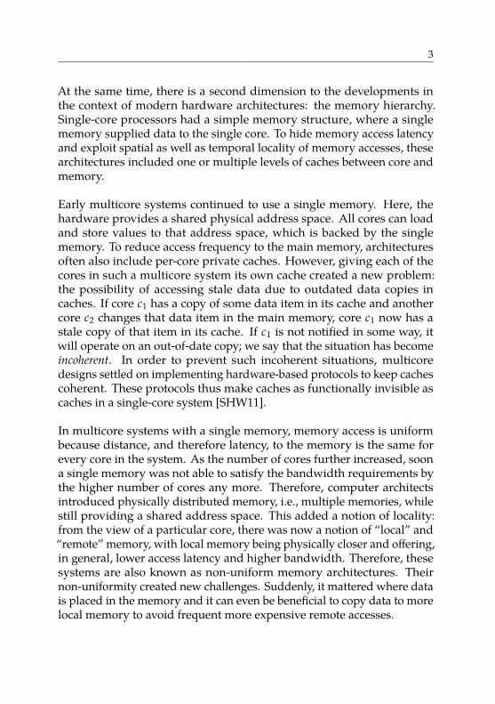
At the same time, there is a second dimension to the developments inthe context of modern hardware architectures: the memory hierarchy.Single-core processors had a simple memory structure, where a singlememory supplied data to the single core. To hide memory access latencyand exploit spatial as well as temporal locality of memory accesses, thesearchitectures included one or multiple levels of caches between core andmemory.
Early multicore systems continued to use a single memory. Here, thehardware provides a shared physical address space. All cores can loadand store values to that address space, which is backed by the singlememory. To reduce access frequency to the main memory, architecturesoften also include per-core private caches. However, giving each of thecores in such a multicore system its own cache created a new problem:the possibility of accessing stale data due to outdated data copies incaches. If core c1 has a copy of some data item in its cache and anothercore c2 changes that data item in the main memory, core c1 now has astale copy of that item in its cache. If c1 is not notified in some way, itwill operate on an out-of-date copy; we say that the situation has becomeincoherent. In order to prevent such incoherent situations, multicoredesigns settled on implementing hardware-based protocols to keep cachescoherent. These protocols thus make caches as functionally invisible ascaches in a single-core system [SHW11].
In multicore systems with a single memory, memory access is uniformbecause distance, and therefore latency, to the memory is the same forevery core in the system. As the number of cores further increased, soona single memory was not able to satisfy the bandwidth requirements bythe higher number of cores any more. Therefore, computer architectsintroduced physically distributed memory, i.e., multiple memories, whilestill providing a shared address space. This added a notion of locality:from the view of a particular core, there was now a notion of “local” and“remote” memory, with local memory being physically closer and offering,in general, lower access latency and higher bandwidth. Therefore, thesesystems are also known as non-uniform memory architectures. Theirnon-uniformity created new challenges. Suddenly, it mattered where datais placed in the memory and it can even be beneficial to copy data to morelocal memory to avoid frequent more expensive remote accesses.
4 1. Introduction
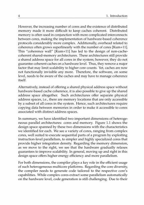
However, the increasing number of cores and the existence of distributedmemory made it more difficult to keep caches coherent. Distributedmemory is often used in conjunction with more complicated interconnectsbetween cores, making the implementation of hardware-based coherenceprotocols considerably more complex. Additionally, overhead related tocoherence often grows superlinearly with the number of cores [Kum+11].This “coherence wall” [Kum+11] has led to the design of non-cache-coherent shared-memory architectures. These architectures still providea shared address space for all cores in the system; however, they do notguarantee coherent caches on a hardware level. Thus, they remove a majorfactor that may limit scalability to higher core counts. Yet, caches are nownot functionally invisible any more. Therefore, the software, on somelevel, needs to be aware of the caches and may have to manage coherenceitself.
Alternatively, instead of offering a shared physical address space withouthardware-based cache coherence, it is also possible to give up the sharedaddress space altogether. Such architectures offer separate physicaladdress spaces, i.e., there are memory locations that are only accessibleby a subset of all cores in the system. Hence, such architectures requirecopying data between memories in order to make it accessible to coresassociated with distinct address spaces.
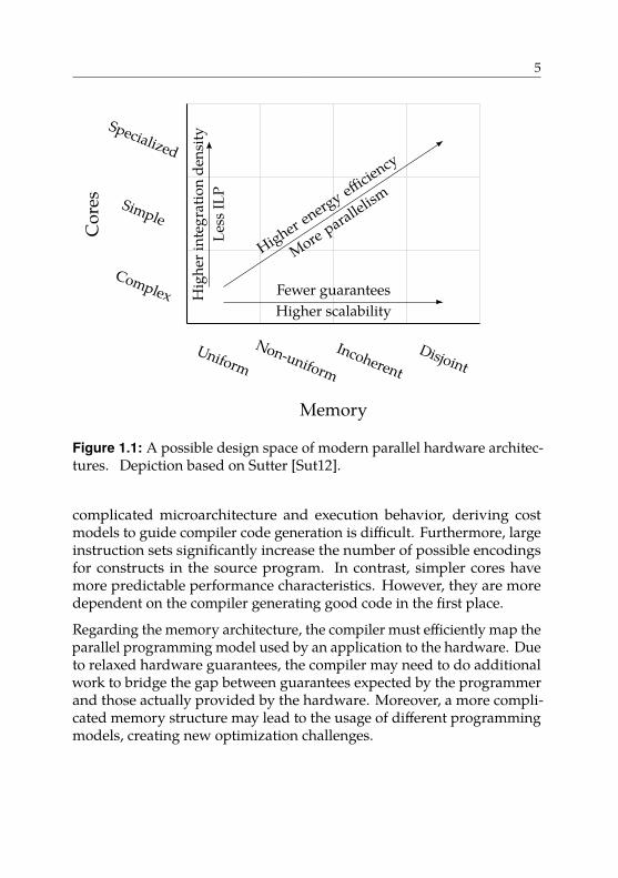
In summary, we have identified two important dimensions of heteroge-neous parallel architectures: cores and memory. Figure 1.1 shows thedesign space spanned by these two dimensions with the characteristicswe identified for each. We see a variety of cores, ranging from complexcores, well suited to execute sequential parts of a program by exploitinginstruction-level parallelism, to simpler and highly specialized cores thatprovide higher integration density. Regarding the memory dimension,as we move to the right, we see that the hardware gradually relaxesguarantees to improve scalability. In general, moving up and right in thisdesign space offers higher energy efficiency and more parallelism.
For both dimensions, the compiler plays a key role in the efficient usageof such heterogeneous multicore platforms. Regarding the core diversity,the compiler needs to generate code tailored to the respective core’scapabilities. While complex cores extract some parallelism automaticallyon the hardware level, code generation is still challenging. Due to their
5
Memory
UniformNon-uniform
IncoherentDisjoint
Fewer guaranteesHigher scalability
Cor
es
Complex
Simple
Specialized
Less
ILP
Hig
heri
nteg
ratio
nde
nsity
Higher energy effi
ciency
More parallel
ism
Figure 1.1: A possible design space of modern parallel hardware architec-tures. Depiction based on Sutter [Sut12].
complicated microarchitecture and execution behavior, deriving costmodels to guide compiler code generation is difficult. Furthermore, largeinstruction sets significantly increase the number of possible encodingsfor constructs in the source program. In contrast, simpler cores havemore predictable performance characteristics. However, they are moredependent on the compiler generating good code in the first place.
Regarding the memory architecture, the compiler must efficiently map theparallel programming model used by an application to the hardware. Dueto relaxed hardware guarantees, the compiler may need to do additionalwork to bridge the gap between guarantees expected by the programmerand those actually provided by the hardware. Moreover, a more compli-cated memory structure may lead to the usage of different programmingmodels, creating new optimization challenges.
6 1. Introduction
Memory
UniformNon-uniform
IncoherentDisjoint
Cor
es
Complex
Simple
Specialized
This dissertation
Contribution 2
Contribution 1
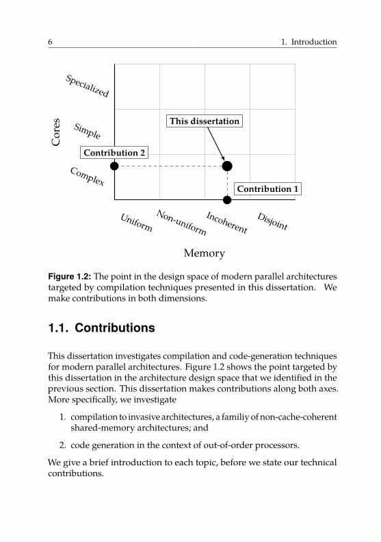
Figure 1.2: The point in the design space of modern parallel architecturestargeted by compilation techniques presented in this dissertation. Wemake contributions in both dimensions.
1.1. Contributions
This dissertation investigates compilation and code-generation techniquesfor modern parallel architectures. Figure 1.2 shows the point targeted bythis dissertation in the architecture design space that we identified in theprevious section. This dissertation makes contributions along both axes.More specifically, we investigate
1. compilation to invasive architectures, a familiy of non-cache-coherentshared-memory architectures; and
2. code generation in the context of out-of-order processors.
We give a brief introduction to each topic, before we state our technicalcontributions.
1.1. Contributions 7
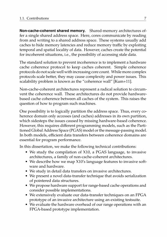
Non-cache-coherent shared memory. Shared-memory architectures of-fer a single shared address space. Here, cores communicate by readingfrom and writing to a shared address space. These systems usually addcaches to hide memory latencies and reduce memory traffic by exploitingtemporal and spatial locality of data. However, caches create the potentialfor incoherent situations, i.e., the possibility of accessing stale data.
The standard solution to prevent incoherence is to implement a hardwarecache coherence protocol to keep caches coherent. Simple coherenceprotocols do not scale well with increasing core count. While more complexprotocols scale better, they may cause complexity and power issues. Thisscalability problem is known as the “coherence wall” [Kum+11].
Non-cache-coherent architectures represent a radical solution to circum-vent the coherence wall. These architectures do not provide hardware-based cache coherence between all caches of the system. This raises thequestion of how to program such machines.
One possibility is to logically partition the address space. Thus, every co-herence domain only accesses (and caches) addresses in its own partition,which sidesteps the issues caused by missing hardware-based coherence.However, this requires different programming models, such as the Parti-tioned Global Address Space (PGAS) model or the message-passing model.In both models, efficient data transfers between coherence domains areessential for program performance.In this dissertation, we make the following technical contributions:
• We study the compilation of X10, a PGAS language, to invasivearchitectures, a family of non-cache-coherent architectures.
• We describe how we map X10’s language features to invasive soft-ware and hardware.
• We study in detail data transfers on invasive architectures.• We present a novel data-transfer technique that avoids serialization
of pointered data structures.• We propose hardware support for range-based cache operations and
consider possible implementations.• We extensively evaluate our data-transfer techniques on an FPGA
prototype of an invasive architecture using an existing testsuite.• We evaluate the hardware overhead of our range operations with an
FPGA-based prototype implementation.
8 1. Introduction
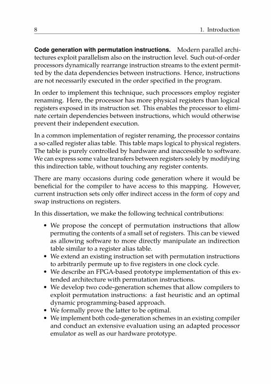
Code generation with permutation instructions. Modern parallel archi-tectures exploit parallelism also on the instruction level. Such out-of-orderprocessors dynamically rearrange instruction streams to the extent permit-ted by the data dependencies between instructions. Hence, instructionsare not necessarily executed in the order specified in the program.
In order to implement this technique, such processors employ registerrenaming. Here, the processor has more physical registers than logicalregisters exposed in its instruction set. This enables the processor to elimi-nate certain dependencies between instructions, which would otherwiseprevent their independent execution.
In a common implementation of register renaming, the processor containsa so-called register alias table. This table maps logical to physical registers.The table is purely controlled by hardware and inaccessible to software.We can express some value transfers between registers solely by modifyingthis indirection table, without touching any register contents.
There are many occasions during code generation where it would bebeneficial for the compiler to have access to this mapping. However,current instruction sets only offer indirect access in the form of copy andswap instructions on registers.
In this dissertation, we make the following technical contributions:
• We propose the concept of permutation instructions that allowpermuting the contents of a small set of registers. This can be viewedas allowing software to more directly manipulate an indirectiontable similar to a register alias table.
• We extend an existing instruction set with permutation instructionsto arbitrarily permute up to five registers in one clock cycle.
• We describe an FPGA-based prototype implementation of this ex-tended architecture with permutation instructions.
• We develop two code-generation schemes that allow compilers toexploit permutation instructions: a fast heuristic and an optimaldynamic programming-based approach.
• We formally prove the latter to be optimal.• We implement both code-generation schemes in an existing compiler
and conduct an extensive evaluation using an adapted processoremulator as well as our hardware prototype.
1.2. Structure 9
Chapter 2: Non-cache-coherent architectures
Chapter 3: Invasive Computing
Chapter 4,Contribution 1:Compilation ofX10 to invasive
architectures
Chapter 5,Contribution 2:
Code generationwith permuta-
tion instructions
Chapter 6: Conclusion
Mem
ory
Cor
es
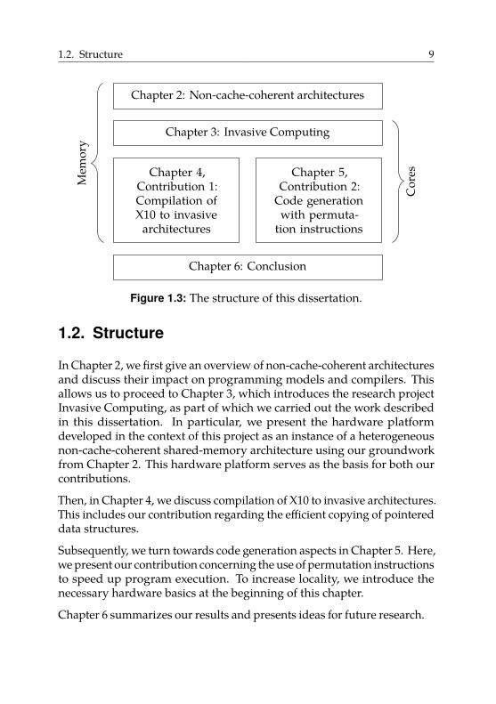
Figure 1.3: The structure of this dissertation.
1.2. Structure
In Chapter 2, we first give an overview of non-cache-coherent architecturesand discuss their impact on programming models and compilers. Thisallows us to proceed to Chapter 3, which introduces the research projectInvasive Computing, as part of which we carried out the work describedin this dissertation. In particular, we present the hardware platformdeveloped in the context of this project as an instance of a heterogeneousnon-cache-coherent shared-memory architecture using our groundworkfrom Chapter 2. This hardware platform serves as the basis for both ourcontributions.
Then, in Chapter 4, we discuss compilation of X10 to invasive architectures.This includes our contribution regarding the efficient copying of pointereddata structures.
Subsequently, we turn towards code generation aspects in Chapter 5. Here,we present our contribution concerning the use of permutation instructionsto speed up program execution. To increase locality, we introduce thenecessary hardware basics at the beginning of this chapter.
Chapter 6 summarizes our results and presents ideas for future research.
10 1. Introduction
1.3. Notation and ConventionsAs the results presented in this dissertation are intimately connected withseveral research projects that have many contributors, this dissertationuses “we” everywhere (except for the acknowledgment section). For thesake of completeness, we include some material that is not the contributionof the author. We explicitly state this fact at the beginning of such sectionsand switch to “Contributor et al.” and “they” if necessary.
We finish our definitions and theorems with a non-filled square � andour proofs with a black square �. We typeset code like this, withkeywords such as if and else highlighted bold. We add hyphens tocompound words if it avoids ambiguities. We use a comma after both“e.g.” and “i.e.”, as proposed by the majority of style guides we consulted.We differentiate between running time (the wall clock time of benchmarkruns), run-time (the point in time when a program runs, in contrast to,e.g., compilation time), and runtime (as a shorthand for runtime library).We use the units and prefixes defined by the standard IEEE 1541-2002.
In printed versions of this dissertation, we provide a DVD with all softwareartifacts produced as part of this dissertation. We also make all artifactsavailable for download. See Appendix B for an overview. All specificsoftware revisions we mention are relative to the projects listed there.
1.4. List of PublicationsIn this section, we give an overview of the author’s publications. Wedifferentiate between publications that contribute to the dissertation athand and those which do not.
The following publications contribute to material presented in this disser-tation. All mentioned talks were given by the author.Manuel Mohr, Artjom Grudnitsky, Tobias Modschiedler, Lars Bauer,Sebastian Hack, and Jörg Henkel. “Hardware Acceleration for Programsin SSA Form”. In: International Conference on Compilers, Architecture and
Synthesis for Embedded Systems. CASES’13. Piscataway, NJ, USA: IEEEPress, 2013, 14:1–14:10. doi: 10.1109/CASES.2013.6662518
Presented on October 1, 2013 in Montréal, Canada.
1.4. List of Publications 11
Matthias Braun, Sebastian Buchwald, Manuel Mohr, and AndreasZwinkau. Dynamic X10: Resource-Aware Programming for Higher Effi-
ciency. Tech. rep. 8. X10 ’14. Karlsruhe Institute of Technology, 2014. url:http://digbib.ubka.uni-karlsruhe.de/volltexte/1000041061
Presented on June 12, 2014 in Edinburgh, Scotland.
Manuel Mohr, Sebastian Buchwald, Andreas Zwinkau, Christoph Erhardt,Benjamin Oechslein, Jens Schedel, and Daniel Lohmann. “Cutting out theMiddleman: OS-Level Support for X10 Activities”. In: Proceedings of the
ACM SIGPLAN Workshop on X10. X10’15. Portland, OR, USA: ACM, 2015,pp. 13–18. isbn: 978-1-4503-3586-7. doi: 10.1145/2771774.2771775
Presented on June 14, 2015 in Portland, USA.
Sebastian Buchwald, Manuel Mohr, and Ignaz Rutter. “Optimal ShuffleCode with Permutation Instructions”. In: Algorithms and Data Structures.Ed. by Frank Dehne, Jörg-Rüdiger Sack, and Ulrike Stege. Vol. 9214.WADS’15. Lecture Notes in Computer Science. Springer InternationalPublishing, 2015, pp. 528–541. doi: 10.1007/978-3-319-21840-3_44Sebastian Buchwald, Manuel Mohr, and Ignaz Rutter. “Optimal ShuffleCode with Permutation Instructions”. In: CoRR abs/1504.07073 (2015).url: http://arxiv.org/abs/1504.07073
Presented on August 5, 2015 in Victoria, Canada.
Manuel Mohr and Carsten Tradowsky. “Pegasus: Efficient Data Transfersfor PGAS Languages on Non-Cache-Coherent Many-Cores”. In: Proceed-
ings of Design, Automation and Test in Europe Conference Exhibition. DATE’17.IEEE, Mar. 2017, pp. 1781–1786. doi: 10.23919/DATE.2017.7927281
Presented on March 30, 2017 in Lausanne, Switzerland.
Matthias Braun, Sebastian Buchwald, Manuel Mohr, and Andreas Zwinkau.An X10 Compiler for Invasive Architectures. Tech. rep. 9. Karlsruhe Instituteof Technology, 2012. url: http://digbib.ubka.uni-karlsruhe.de/volltexte/1000028112
12 1. Introduction
The following publications do not contribute to material presented in thisdissertation.
Jonathan Aldrich, Ronald Garcia, Mark Hahnenberg, Manuel Mohr,Karl Naden, Darpan Saini, Sven Stork, Joshua Sunshine, Éric Tanter,and Roger Wolff. “Permission-Based Programming Languages (NIERtrack)”. In: Proceedings of the 33rd International Conference on Software
Engineering. ICSE ’11. New York, NY, USA: ACM, 2011, pp. 828–831. doi:10.1145/1985793.1985915
Sven Stork, Karl Naden, Joshua Sunshine, Manuel Mohr, Alcides Fonseca,Paulo Marques, and Jonathan Aldrich. “AEminium: A Permission BasedConcurrent-by-Default Programming Language Approach”. In: ACM
Transactions on Programming Languages and Systems. TOPLAS 36.1 (Mar.2014), 2:1–2:42. doi: 10.1145/2543920
Sebastian Buchwald, Manuel Mohr, and Andreas Zwinkau. “MalleableInvasive Applications”. In: Proceedings of the 8th Working Conference on
Programming Languages. ATPS’15. Springer Berlin Heidelberg, 2015,pp. 123–126
Alexander Pöppl, Marvin Damschen, Florian Schmaus, Andreas Fried,Manuel Mohr, Matthias Blankertz, Lars Bauer, Jörg Henkel, WolfgangSchröder-Preikschat, and Michael Bader. “Shallow Water Waves on aDeep Technology Stack: Accelerating a Finite Volume Tsunami Modelusing Reconfigurable Hardware in Invasive Computing”. In: Euro-Par
2017: Parallel Processing Workshops. Lecture Notes in Computer Science.Heidelberg, Berlin: Springer-Verlag, Aug. 2017
There are only two hard things in Computer Science:
naming things, cache invalidation, and off-by-1 errors.
Leon Bambrick, based on quote by Phil Karlton 2Non-Cache-Coherent Architectures
In this chapter, we give an overview of non-cache-coherent shared-memoryarchitectures. First, we cover fundamentals about parallel hardware archi-tectures. Then, we give a more precise definition of cache coherence andpresent hardware-based and software-based implementation techniques.Subsequently, we discuss reasons for abandoning hardware-based coher-ence and give examples of resulting architectures. Lastly, we investigatethe impact of missing hardware-based coherence on programming modelsand compilers.
2.1. A Taxonomy of Parallel Architectures
In this section, we give an overview of different types of parallel hardwarearchitectures. We base our presentation on [HP11], but deviate in somedetails. We look at two orthogonal aspects:
1. How is memory organized?
2. How do cores communicate?
13
14 2. Non-Cache-Coherent Architectures
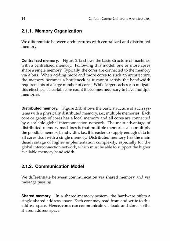
2.1.1. Memory Organization
We differentiate between architectures with centralized and distributedmemory.
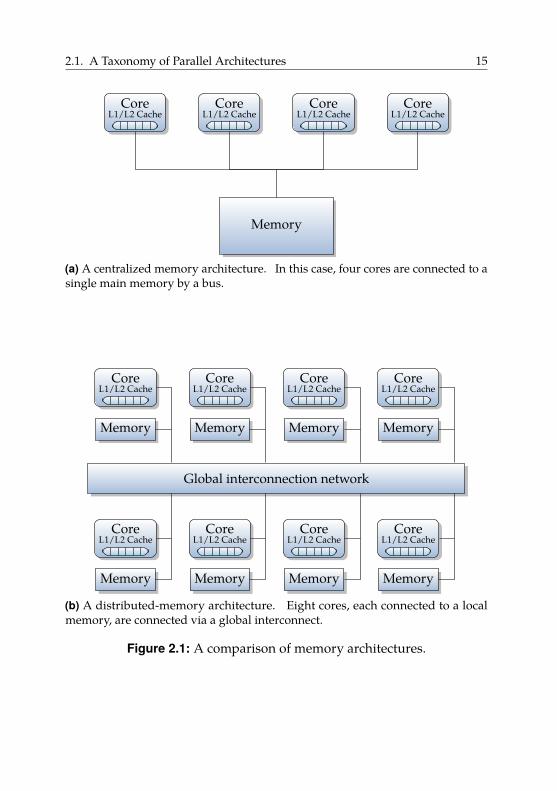
Centralized memory. Figure 2.1a shows the basic structure of machineswith a centralized memory. Following this model, one or more coresshare a single memory. Typically, the cores are connected to the memoryvia a bus. When adding more and more cores to such an architecture,the memory becomes a bottleneck as it cannot satisfy the bandwidthrequirements of a large number of cores. While larger caches can mitigatethis effect, past a certain core count it becomes necessary to have multiplememories.
Distributed memory. Figure 2.1b shows the basic structure of such sys-tems with a physically distributed memory, i.e., multiple memories. Eachcore or group of cores has a local memory and all cores are connectedby a scalable global interconnection network. The main advantage ofdistributed-memory machines is that multiple memories also multiplythe possible memory bandwidth, i.e., it is easier to supply enough data toall cores than with a single memory. Distributed memory has the maindisadvantage of higher implementation complexity, especially for theglobal interconnection network, which must be able to support the higheravailable memory bandwidth.
2.1.2. Communication Model
We differentiate between communication via shared memory and viamessage passing.
Shared memory. In a shared-memory system, the hardware offers asingle shared address space. Each core may read from and write to thisaddress space. Hence, cores can communicate via loads and stores to theshared address space.
2.1. A Taxonomy of Parallel Architectures 15
CoreL1/L2 Cache
CoreL1/L2 Cache
CoreL1/L2 Cache
CoreL1/L2 Cache
Memory
(a) A centralized memory architecture. In this case, four cores are connected to asingle main memory by a bus.
CoreL1/L2 Cache
Memory
CoreL1/L2 Cache
Memory
CoreL1/L2 Cache
Memory
CoreL1/L2 Cache
Memory
CoreL1/L2 Cache
Memory
CoreL1/L2 Cache
Memory
CoreL1/L2 Cache
Memory
CoreL1/L2 Cache
Memory
Global interconnection network
(b) A distributed-memory architecture. Eight cores, each connected to a localmemory, are connected via a global interconnect.
Figure 2.1: A comparison of memory architectures.
16 2. Non-Cache-Coherent Architectures
Message passing. In a pure message-passing system, the hardware doesnot offer a shared address space. Hence, it is not assumed that everycore can access all available memory. Thus, in general, cores cannot sharedata and therefore communicate by sending explicit messages. Passing amessage is inherently linked to copying the necessary data to the receiver’saddress space as otherwise the receiver is unable to access the data.
2.1.3. Typical CombinationsIn theory, memory organization and communication model are com-pletely independent. In practice, the following three combinations areimportant.
Shared memory with centralized memory. Machines that provide sharedmemory with a single centralized memory are often called symmetric mul-
tiprocessing (SMP) systems. As all cores have the same distance from thesingle main memory, they also have the same access latency. Therefore,these machines are also called uniform memory access (UMA) architectures.This is the most popular type of memory organization for single-core andmulti-core machines.
Shared memory with distributed memory. Machines that provide sharedmemory with distributed memory are usually referred to as distributed
shared-memory (DSM) architectures. Here, the hardware still provides asingle address space, hence every core can still access the complete memory.However, there is now a notion of locality as accessing a local memoryis faster than accessing a remote memory. Therefore, these machines arealso called non-uniform memory access (NUMA) architectures. The NUMAmodel is the standard for today’s server machines. Typically, this is dueto the memory controller being integrated into the processor. Hence, assoon as a machine possesses multiple physical processors, i.e., CPUs inmultiple sockets, it automatically becomes a NUMA architecture.
Message passing with distributed memory. Such machines typicallyprovide multiple private address spaces. Each core or group of cores hasits own private address space, which is not addressable by remote cores.
2.2. Cache Coherence 17
Hence, the same physical address can refer to different memory locationsfor different cores. A typical representative of this class of machines is acluster computer. Often, clusters are not pure message-passing systems.For efficiency reasons, shared memory is offered and used for small groupsof cores, e.g., one node of a cluster, and message passing is used betweencore groups.
2.2. Cache Coherence
Usually, systems introduce caches to exploit spatial and temporal localityof data accesses. Typically, every memory address accessed by a core isfirst looked up in the core’s cache. For example, when a core loads frommemory address A, it is first checked if there is a valid copy of the datafrom A in the cache. This is called a cache hit, where the cache returns thevalue from the local data copy without consulting the memory. Only incase of a cache miss is the memory actually accessed.
In a shared-memory system with multiple cores, the caching of data canlead to incoherent situations unless special measures are taken. In general,incoherence refers to a situation where stale, i.e., outdated, data is accessed.As an example, suppose that we have two cores c1 and c2, each with aprivate cache. Further, suppose that the shared memory holds the value100 at address A. First, both cores read from A and therefore have copiesof that datum (100) in their local caches. Now, c1 writes the value 200 to A.After the write by c1, c2 reads from A. If we do not take any precautions,the situation has now become incoherent, as c2 would still read the oldvalue 100 from its cache.
In practice, this incoherent situation is prevented by using a coherenceprotocol. In our example, this protocol must prevent c2 from observingthe old value while c1 observes the new value. There exist numerouspossible protocol variants and even more implementation possibilities,but all protocols have in common that they maintain coherence invariants.To understand what a coherence protocol must accomplish, first we haveto define coherence in a precise manner.
18 2. Non-Cache-Coherent Architectures
We follow the definition by Sorin et al. [SHW11, section 2.3]. Sorin et al.use the single-writer-multiple-reader (SWMR) invariant as the foundationfor their definition of coherence. The SWMR invariant states that, for anygiven memory location M at any given moment in time, there is
(i) either a single core that may read and write M, or(ii) any number of cores that may only read M.
Especially, there must not exist a point in time, so that some memorylocation M may be written by a core and at the same time read or writtenby another core.
Sorin et al. propose another way of viewing this definition. They dividethe lifetime of each memory location into epochs. Viewed this way, duringeach epoch there must be either a single core with read-write access orany number of cores with read-only access.
However, the SWMR invariant alone is not enough to capture our intuitiveunderstanding of coherence. For example, in an epoch where two coreshave read access to a memory location, the SWMR invariant does not stateanything about the values that the cores read. Hence, it would be allowedthat they read different values. Clearly, this is an incoherent situation likethe one from our first example and therefore we must complement theSWMR invariant.
Sorin et al. add the data-value invariant. This invariant regulates thepropagation of values from one epoch to the next. More precisely, it statesthat the value of a memory location M at the start of an epoch is the sameas the value of M at the end of M’s last read-write epoch.
Definition 1 We call a system coherent if the following two invariantshold [SHW11, p. 13]:
1. Single-Writer, Multiple-Reader (SWMR) Invariant: For any memorylocation M, at any given (logical) time, there is only a single corethat may write to M (and can also read it), or any number of cores(possibly zero) that may only read M.
2. Data-Value Invariant: The value of a memory location M at the startof an epoch is the same as the value of M at the end of M’s lastread-write epoch. 2
2.2. Cache Coherence 19
Core c1:
S1 : x ← 1L1 : r1 ← y
Core c2:
S2 : y ← 1L2 : r2 ← x
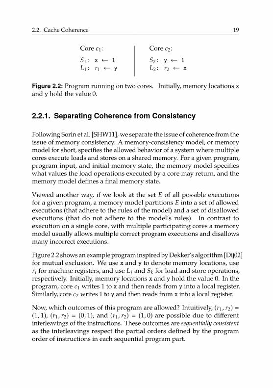
Figure 2.2: Program running on two cores. Initially, memory locations xand y hold the value 0.
2.2.1. Separating Coherence from Consistency
Following Sorin et al. [SHW11], we separate the issue of coherence from theissue of memory consistency. A memory-consistency model, or memorymodel for short, specifies the allowed behavior of a system where multiplecores execute loads and stores on a shared memory. For a given program,program input, and initial memory state, the memory model specifieswhat values the load operations executed by a core may return, and thememory model defines a final memory state.
Viewed another way, if we look at the set E of all possible executionsfor a given program, a memory model partitions E into a set of allowedexecutions (that adhere to the rules of the model) and a set of disallowedexecutions (that do not adhere to the model’s rules). In contrast toexecution on a single core, with multiple participating cores a memorymodel usually allows multiple correct program executions and disallowsmany incorrect executions.
Figure 2.2 shows an example program inspired by Dekker’s algorithm [Dij02]for mutual exclusion. We use x and y to denote memory locations, useri for machine registers, and use L j and Sk for load and store operations,respectively. Initially, memory locations x and y hold the value 0. In theprogram, core c1 writes 1 to x and then reads from y into a local register.Similarly, core c2 writes 1 to y and then reads from x into a local register.
Now, which outcomes of this program are allowed? Intuitively, (r1 , r2) �(1, 1), (r1 , r2) � (0, 1), and (r1 , r2) � (1, 0) are possible due to differentinterleavings of the instructions. These outcomes are sequentially consistent
as the interleavings respect the partial orders defined by the programorder of instructions in each sequential program part.
20 2. Non-Cache-Coherent Architectures
c1 c2 coherence state of x coherence state of yL1 read-only for noone read-only for c1
L2 read-only for c2 read-only for c1S1 read-write for c1 read-only for c1
S2 read-write for c1 read-write for c2
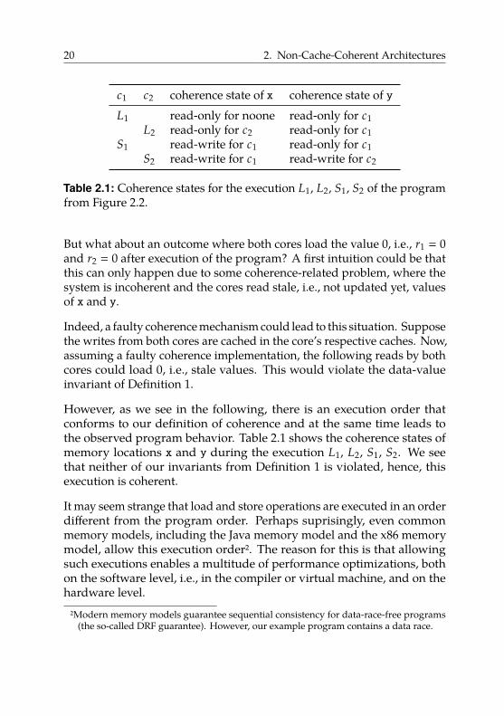
Table 2.1: Coherence states for the execution L1, L2, S1, S2 of the programfrom Figure 2.2.
But what about an outcome where both cores load the value 0, i.e., r1 � 0and r2 � 0 after execution of the program? A first intuition could be thatthis can only happen due to some coherence-related problem, where thesystem is incoherent and the cores read stale, i.e., not updated yet, valuesof x and y.
Indeed, a faulty coherence mechanism could lead to this situation. Supposethe writes from both cores are cached in the core’s respective caches. Now,assuming a faulty coherence implementation, the following reads by bothcores could load 0, i.e., stale values. This would violate the data-valueinvariant of Definition 1.
However, as we see in the following, there is an execution order thatconforms to our definition of coherence and at the same time leads tothe observed program behavior. Table 2.1 shows the coherence states ofmemory locations x and y during the execution L1, L2, S1, S2. We seethat neither of our invariants from Definition 1 is violated, hence, thisexecution is coherent.
It may seem strange that load and store operations are executed in an orderdifferent from the program order. Perhaps suprisingly, even commonmemory models, including the Java memory model and the x86 memorymodel, allow this execution order2. The reason for this is that allowingsuch executions enables a multitude of performance optimizations, bothon the software level, i.e., in the compiler or virtual machine, and on thehardware level.
2Modern memory models guarantee sequential consistency for data-race-free programs(the so-called DRF guarantee). However, our example program contains a data race.
2.2. Cache Coherence 21
For example, if a compiler can prove that x and y from Figure 2.2 donot alias, i.e., always refer to distinct memory locations, the compileris allowed to generate code that first loads a value and then stores theother, even if in the program the write precedes the read3. Similarly, theCPU cache may include write buffers to hold data that must be written tomemory. The buffer enables the cache to service following load operationswithout waiting for the memory to actually finish writing back the valueof the store operation, effectively allowing a load to overtake a precedingstore.
Hence, it is useful to separate the concepts of cache coherence andmemory consistency. Sorin et al. give two more reasons why these aretwo separate issues. First, an important difference between coherence andconsistency is that coherence is only concerned with a single memorylocation, while memory-consistency models consider accesses to multiplememory locations. This is also apparent in Definition 1, which only dealswith accesses by multiple cores to a single memory location. And second,the question of whether the discussed execution of the program fromFigure 2.2 is allowed also arises in a system without any caches. In such asystem, there is clearly no need for cache coherence; however, it still needsa memory model. In practice, most implementations of memory modelsassume and exploit cache coherence.
2.2.2. Implementation
Definition 1 tells us what a coherence protocol must achieve but nothow it can maintain these invariants. Again, we have orthogonal designdecisions: we can choose between different coherence policies; we canchoose a granularity; and we can put the responsibility for implementingcoherence onto hardware or software.
The implementation of a coherence protocol often depends on the cacheconfiguration. We can configure caches in write-through or write-back
mode. Write-through caches update the main memory on every write.Hence, the main memory always contains an up-to-date value for a certain
3All modern programming languages that define a memory model offer means to restrictsuch reorderings, e.g., by using the keyword volatile [Gos+14, section 17.4] in Java.
22 2. Non-Cache-Coherent Architectures
address. Write-back caches do not update the main memory on everywrite. Therefore, with multiple write-back caches, it is more difficult tofind the most up-to-date value of a data item, as it can be solely located inone of the caches. In such a case, cache terminology usually refers to thiscopy as dirty. In general, write-through caches are simpler to implementbut have higher main-memory-bandwidth requirements.
2.2.2.1. Coherence Policy
In general, we can classify a coherence policy as either write-invalidate
or write-update [Ste90; PP84]. Both types of policies must maintain theinvariants from Definition 1.
Write-invalidate policies maintain coherence as follows. When a corec updates its local data copy of memory location L, write-invalidatepolicies enforce the invalidation of all other copies of L. Hence, the SWMRinvariant is maintained by forcing the coherence state of L to “read-writefor c”. The next time another core c′ reads L, either c provides the newvalue directly to c′, or c first writes back its local value to memory locationL, where c′ then fetches it from.
With a write-update policy, when a core updates its local data copy ofmemory location L, at the same time, it updates all other copies of L.Hence, the SWMR invariant is maintained by forcing the coherence stateof L directly to “read-only for all cores that had a copy of L”. The policyimplementation decides whether the copy in memory is updated as well.
Write-invalidate policies distribute updated data items lazily, while write-update policies do so eagerly. In general, write-invalidate policies are farmore common than write-update policies.
2.2.2.2. Granularity
Common processors can perform loads and stores at various granularities,usually ranging at least from 1 to 8 bytes, and sometimes including widememory operations, e.g., 64 bytes for vector instructions. In theory, itwould be possible to manage coherence at the finest granularity, i.e., 1 byte.
2.2. Cache Coherence 23
However, this would considerably increase overhead for implementationand coherence traffic.
Therefore, in practice, implementations manage coherence at a coarsergranularity, most commonly cache lines. Enforcing the coherence invari-ants per cache line is, in general, more efficient, as they comprise multiplebytes (16–64 bytes are common). However, managing coherence at acoarse granularity can also cause other performance problems, such asfalse sharing [BS93].
False sharing occurs when multiple cores access and modify different,non-overlapping data objects within the same cache line. For example,suppose that core c1 repeatedly modifies memory location L1, core c2repeatedly modifies memory location L2 (different from L1), and L1 andL2 happen to be part of the same cache line. Here, the coherence protocolstill maintains the SWMR invariant for the whole cache line. Hence,every time c1 modifies L1, a coherence action is triggered. For example,assuming a write-invalidate protocol, c2’s cache line containing L2 isinvalidated, although L2 did not change at all. The same happens forc1’s cache line containing a copy of L1 on the next update to L2 by c2.Thus, an unfortunate combination of memory layout, access behavior, andcoherence granularity can lower performance significantly.
2.2.2.3. Responsibility
We can implement the system that maintains the coherence invariantseither in hardware or in software [Adv+91; TM97].
Hardware-based coherence. If we implement coherence in hardware, itis functionally invisible to software. Hence, for a shared-memory systemwith hardware-based cache coherence, the caches behave like in a single-core system. Correctly implemented, hardware-based cache coherencemakes it impossible for the programmer to determine whether a systemhas caches by inspecting the results of load and store operations [SHW11].However, it may be possible to deduce the presence of caches using timinginformation.
24 2. Non-Cache-Coherent Architectures
In the following, we give a brief overview of the two most important im-plementation techniques for hardware-based cache coherence: snoopingprotocols and directory schemes. Snooping protocols rely on a mediumthat is able to broadcast information, e.g., a bus, and distribute the infor-mation about the sharing status of each memory block. On the other hand,directory schemes centralize the information about the sharing status ofmemory blocks in one location, called the directory. As a consequence,they do not require the ability to broadcast information. In general,snooping protocols are easy and cheap to implement, while directoryschemes are more complex, but scale to higher core counts. We base ourpresentation on Hennessy et al.’s [HP11] and also refer to the same sourcefor details.
The idea behind snooping protocols is that addresses are broadcast on theshared medium (e.g., a bus) and all participants observe, or “snoop”, theseaddresses to potentially trigger actions in their respective local cachesto maintain coherence [HP11, section 4.2]. To illustrate this idea, wediscuss the implementation of a snooping coherence protocol for a simplememory architecture using a bus as shown in Figure 2.1a. We assume awrite-invalidate policy, as it is the most commonly used strategy.
As an example, suppose we have two cores c1 and c2 in such a system,each with a private cache configured in write-back mode. If c1 readsfrom address L, it puts a copy of the data at address L in its local cache.Suppose c2 now wants to write a new value to L, which proceeds asfollows. After c2 has successfully acquired bus access4, it broadcasts aninvalidate operation on the bus. Core c1 reacts by invalidating its localcopy of L, i.e., the next access to L by c1 will cause a cache miss. Then, c2performs the actual write operation. With write-back caches, now onlyc2’s cache holds the new value of L; the copy of L in c1’s cache is markedinvalid and the copy in memory is outdated.
If c1 now reads from L again, we must (i) somehow notice that readingfrom main memory is incorrect (as the new value is in c2’s cache), and(ii) transport the new value to c1’s cache. Fortunately, we can implementthe notification mechanism exactly as with the original write describedbefore. Thus, we require caches to also observe read operations on the
4If multiple cores want to write to the same address L concurrently, the bus-acquisitionprocess serializes their write operations.
2.2. Cache Coherence 25
bus and to check if they have a modified copy of the data at the requestedaddress. If this is the case, they abort the other core’s memory access andthen provide the new value. In our example, c2 would see c1’s read to Lon the bus and then abort it.
How exactly then c2 makes the new value available to c1 is anotherdesign decision. One option is that c2 writes back the new value tomain memory and then sends a retry signal to c1, which restarts theread operation. The alternative is that c2 sends the new value directlyto c1, without a detour via main memory. The first option is easier toimplement but potentially slower as updated values are distributed viamain memory. The second option requires additional bookkeeping andincreases implementation complexity, but distributes updated valuesover a potentially faster interconnect between cores, without involvingmain memory. This design decision differentiates the two well-knowncoherence protocols MESI [PP84] and MOESI [Adv10, section 7.3].
As we have seen, bus snooping protocols need to broadcast, i.e., commu-nicate with all other caches, on every cache miss. On a read miss, wehave to inform all other caches of our intent to read the address and theymight respond by aborting our read request, followed by providing theupdated data item. On a write miss, we also have to inform all othercaches as they might need to invalidate their copy. In total, the amount ofcoherence-related traffic can soon overwhelm the capabilities of the busas we increase the number of cores (and caches).
An alternative offering better scalability are directory protocols [HP11,section 4.4]. They build upon the idea of the directory, which is a datastructure that holds the sharing status of each cacheable memory block.The most important improvement compared to snooping-based protocolsis that we save the sharing status of a block in a single, well-definedlocation (the directory) instead of replicating information in multiplelocations. This avoids the need to broadcast information to synchronizemultiple copies of the sharing status.
However, we can still distribute the directory itself. Directory schemesare often used for distributed shared-memory machines as depicted inFigure 2.1b. In such a setting, each core with its local cache and localmemory is extended with a directory responsible for the memory blocksin the respective local memory. Hence, while the sharing information is
26 2. Non-Cache-Coherent Architectures
distributed, it is not replicated, as we save the current sharing status ofeach memory block in exactly one location.
In their simplest form, directory schemes maintain one directory entryper memory block. Each entry holds the block’s current sharing status. Abasic protocol differentiates between the following sharing states (withmore fine-grained states allowing potentially higher performance at thecost of increased complexity):
Uncached: No core has a copy of the memory block.
Shared: The block is cached by at least one core, and the values of thisblock in memory and in all caches match. This means no core hasmodified the block. Additionally, we have to save information aboutwhich cores have copies of the block in their caches (the sharer set).
Modified: Exactly one core (the owner) has a copy of the block, and theblock is modified. Hence, the copy in memory is outdated. We alsosave which core is the owner.
In a directory scheme, up to three types of cores may be involved in amemory access:
• the local requesting core that reads or writes the cache block;• the home core whose memory holds the requested cache block; and• the remote core whose cache holds a copy of the requested cache
block.
As an example, suppose we have three cores c1, c2, and c3 in a DSM systemas shown in Figure 2.1b, each with private write-back caches. We assumethat initially, all caches are empty, i.e., all entries in all directories are setto Uncached. Furthermore, we assume memory location L is physicallylocated in c1’s memory.
Now, suppose that in our example c1 reads from L. Here, c1 is both thelocal and the home core; no remote core is involved as all caches are empty.Hence, c1 puts L in its local cache and updates in its local directory thestate of L to Shared as well as the respective sharer set to {c1}.
Now, assume that c2 reads L next. The local core c2 then sends a readrequest to home core c1, which adds core 2 to the set of sharers registeredfor L in c1’s directory, and then returns the data at L to c2.
2.2. Cache Coherence 27
Now, suppose that the next action is a write to L by c3. Hence, thelocal core c3 sends a write request to home core c1. Core c1 responds by(i) sending the requested block back to c3, (ii) reading the set {c1 , c2} ofsharers and sending them invalidation requests, and (iii) setting the stateof L to Modified in c1’s directory while registering c3 as the owner. Coresc1 and c2 then invalidate their local copies of L.
In summary, directory schemes scale better than snooping-based protocolsas they do not depend on broadcasts. However, they are also difficultto scale to large numbers of cores. For example, the sharer set is oftenimplemented as a bit set with one bit per core, where a 1 at position imeans that core ci currently has a copy of the respective memory locationin its cache. For 1024 cores, storing the bit set requires 128 bytes, whichmay be more than the size of the memory block whose sharing state the bitset is supposed to track. Another issue is the significantly increased powerusage due to the high number of messages for coherence traffic [KK10].
Software-based coherence. Alternatively, coherence can be implementedin software. This means that the software must trigger necessary cacheoperations, such as invalidations and write-backs. To be able to do that,the hardware must provide appropriate support. In the context of thefollowing discussion, we assume the existence of an invalidation instructionand a writeback instruction with the following semantics:
• The invalidation instruction invalidate L takes a memory locationL as an operand and invalidates the copy of L in the executing core’scache (if a copy is present). This enforces that L is fetched frommain memory on the next access. Note that invalidating a locallymodified copy discards these local changes.
• The writeback instruction writeback L takes a memory location Las an operand and writes the copy of L in the executing core’s cacheback to memory (if a copy exists and it has been modified locally).
We can implement these instructions as part of the cache logic. Forexample, the invalidation instruction looks up L in the cache and in caseof a cache hit, marks the respective cache line as invalid, e.g., by clearingthe cache line’s valid bit. We can implement the writeback instructionsimilarly.
28 2. Non-Cache-Coherent Architectures
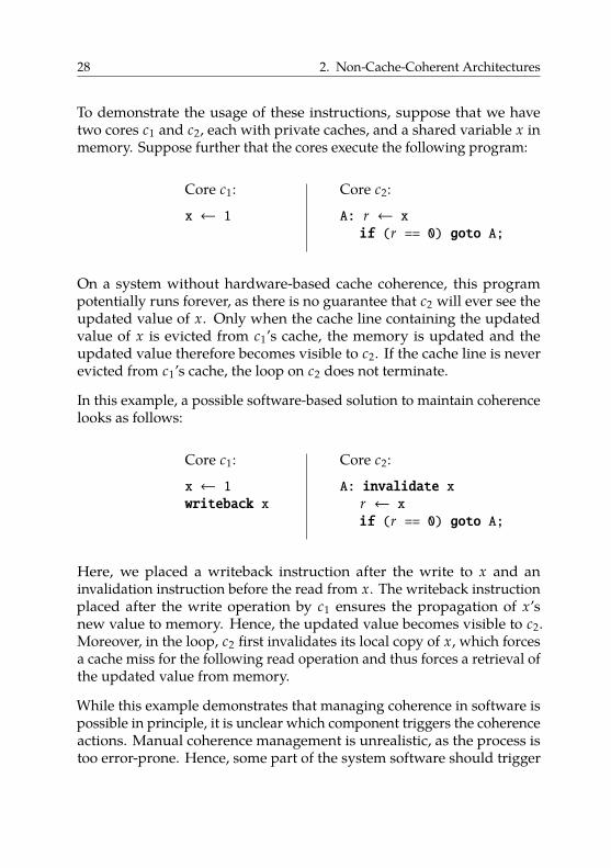
To demonstrate the usage of these instructions, suppose that we havetwo cores c1 and c2, each with private caches, and a shared variable x inmemory. Suppose further that the cores execute the following program:
Core c1:
x ← 1
Core c2:
A: r ← xif (r == 0) goto A;
On a system without hardware-based cache coherence, this programpotentially runs forever, as there is no guarantee that c2 will ever see theupdated value of x. Only when the cache line containing the updatedvalue of x is evicted from c1’s cache, the memory is updated and theupdated value therefore becomes visible to c2. If the cache line is neverevicted from c1’s cache, the loop on c2 does not terminate.
In this example, a possible software-based solution to maintain coherencelooks as follows:
Core c1:
x ← 1writeback x
Core c2:
A: invalidate xr ← xif (r == 0) goto A;
Here, we placed a writeback instruction after the write to x and aninvalidation instruction before the read from x. The writeback instructionplaced after the write operation by c1 ensures the propagation of x’snew value to memory. Hence, the updated value becomes visible to c2.Moreover, in the loop, c2 first invalidates its local copy of x, which forcesa cache miss for the following read operation and thus forces a retrieval ofthe updated value from memory.
While this example demonstrates that managing coherence in software ispossible in principle, it is unclear which component triggers the coherenceactions. Manual coherence management is unrealistic, as the process istoo error-prone. Hence, some part of the system software should trigger
2.2. Cache Coherence 29
the cache operations, e.g., the operating system, a library, or the compileras in our example.
In general, we can classify software-based coherence schemes as eitherstatic or dynamic [TM97]. Static schemes are compiler-based and rely onprogram analysis at compile time. Dynamic schemes are implemented inoperating systems or libraries and monitor memory-access behavior atrun-time. We discuss this topic in more detail in Section 2.4.2, but give anintuition of the trade-offs here.
For static schemes, the compiler must identify potentially conflictingaccesses to shared data and extend the program to trigger cache operationsat appropriate program points, e.g., by generating additional instructionsas seen in our example. To guarantee correctness, compilers must beconservative and assume the worst case when adding coherence-relatedactions to the program. Clearly, the compiler can insert cache operationsbefore and after each memory-access operation. However, this effectivelydisables the system’s caches.
Hence, to make static schemes viable performance-wise, the compilerhas to reduce the number of inserted cache operations. The fundamentalproblem is that compile-time information must be used to predict run-timeaccess behavior. This works well for programs with a regular predictableaccess behavior. However, for programs with an irregular memory-accessbehavior, many unnecessary coherence actions may be performed atrun-time, lowering performance significantly.
For dynamic schemes, a library or the operating system maintains cachecoherence at run-time. Operating systems usually exploit virtual memoryto manage coherence at page granularity (a typical page size is 4 KiB).They enforce the SWMR invariant for pages: if a core writes to a sharedpage, this page must be invalidated on all other cores. The next timeanother core accesses the shared page, the page-fault handler managescoherence in software, e.g., by writing back the changed page contentson the core that previously wrote to it. Similarly, libraries can managecoherence in software at the granularity of objects or memory regions.
Dynamic schemes detect problematic accesses at run-time, so they may re-duce unnecessary coherence actions. However, in order to limit coherence-related overhead, they have to work on a coarser granularity, such as
30 2. Non-Cache-Coherent Architectures
whole pages. Depending on the memory layout and access behavior ofthe program, false sharing (cf. Section 2.2.2.2) can decrease performancesignificantly.
Overall, software-managed coherence was a field of active research inthe 1980s and 1990s. Tartalja et al. [TM97] and Stenström [Ste90] pro-vide overviews and classifications of early software-based coherenceschemes. Ultimately, however, hardware-based cache coherence becamethe standard for shared-memory multi-core architectures. Snooping-based protocols were reasonably simple to implement and offered goodperformance. Most importantly, hardware-based cache coherence enablesall parallel software and their respective tools, such as compilers, to beoblivious to the existence of caches.
However, more recently, software-based coherence has regained interestin the context of non-cache-coherent many-core architectures. Such archi-tectures do not implement hardware-based coherence; their propertiesand the implications are the topic of the next sections.
2.3. Hardware Architecture
Shared-memory multi-core architectures as described in Section 2.1 withhardware-based cache coherence as described in Sections 2.2 and 2.2.2.3are by far the most common type of machine currently in use. Recently,however, non-cache-coherent shared-memory architectures have becomeattractive for two reasons: power and scalability.
Power. In power-constrained contexts, such as mobile computing, (par-tially) giving up cache coherence can enable more aggressive powersavings. As an example, many multi-core systems in modern mobilephones consist of a group of “strong” cores and a group of “weak”cores [Tex14; LWZ14]. The idea is to use the weak cores when the systemis not actively used and to switch to the strong cores for more demandingtasks.
However, hardware-based coherence between weak and strong coresrestricts the architectural asymmetry, i.e., it prevents the weak cores from
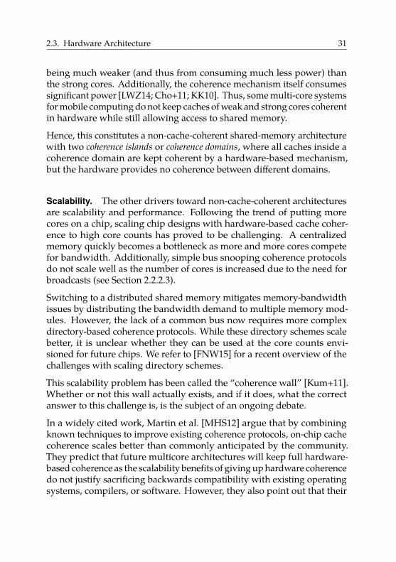
2.3. Hardware Architecture 31
being much weaker (and thus from consuming much less power) thanthe strong cores. Additionally, the coherence mechanism itself consumessignificant power [LWZ14; Cho+11; KK10]. Thus, some multi-core systemsfor mobile computing do not keep caches of weak and strong cores coherentin hardware while still allowing access to shared memory.
Hence, this constitutes a non-cache-coherent shared-memory architecturewith two coherence islands or coherence domains, where all caches inside acoherence domain are kept coherent by a hardware-based mechanism,but the hardware provides no coherence between different domains.
Scalability. The other drivers toward non-cache-coherent architecturesare scalability and performance. Following the trend of putting morecores on a chip, scaling chip designs with hardware-based cache coher-ence to high core counts has proved to be challenging. A centralizedmemory quickly becomes a bottleneck as more and more cores competefor bandwidth. Additionally, simple bus snooping coherence protocolsdo not scale well as the number of cores is increased due to the need forbroadcasts (see Section 2.2.2.3).
Switching to a distributed shared memory mitigates memory-bandwidthissues by distributing the bandwidth demand to multiple memory mod-ules. However, the lack of a common bus now requires more complexdirectory-based coherence protocols. While these directory schemes scalebetter, it is unclear whether they can be used at the core counts envi-sioned for future chips. We refer to [FNW15] for a recent overview of thechallenges with scaling directory schemes.
This scalability problem has been called the “coherence wall” [Kum+11].Whether or not this wall actually exists, and if it does, what the correctanswer to this challenge is, is the subject of an ongoing debate.
In a widely cited work, Martin et al. [MHS12] argue that by combiningknown techniques to improve existing coherence protocols, on-chip cachecoherence scales better than commonly anticipated by the community.They predict that future multicore architectures will keep full hardware-based coherence as the scalability benefits of giving up hardware coherencedo not justify sacrificing backwards compatibility with existing operatingsystems, compilers, or software. However, they also point out that their
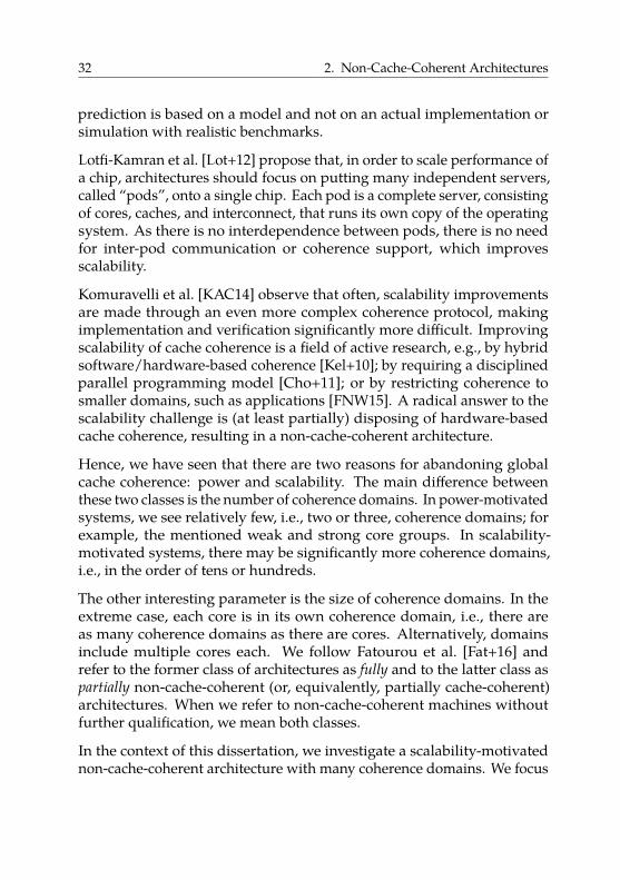
32 2. Non-Cache-Coherent Architectures
prediction is based on a model and not on an actual implementation orsimulation with realistic benchmarks.
Lotfi-Kamran et al. [Lot+12] propose that, in order to scale performance ofa chip, architectures should focus on putting many independent servers,called “pods”, onto a single chip. Each pod is a complete server, consistingof cores, caches, and interconnect, that runs its own copy of the operatingsystem. As there is no interdependence between pods, there is no needfor inter-pod communication or coherence support, which improvesscalability.
Komuravelli et al. [KAC14] observe that often, scalability improvementsare made through an even more complex coherence protocol, makingimplementation and verification significantly more difficult. Improvingscalability of cache coherence is a field of active research, e.g., by hybridsoftware/hardware-based coherence [Kel+10]; by requiring a disciplinedparallel programming model [Cho+11]; or by restricting coherence tosmaller domains, such as applications [FNW15]. A radical answer to thescalability challenge is (at least partially) disposing of hardware-basedcache coherence, resulting in a non-cache-coherent architecture.
Hence, we have seen that there are two reasons for abandoning globalcache coherence: power and scalability. The main difference betweenthese two classes is the number of coherence domains. In power-motivatedsystems, we see relatively few, i.e., two or three, coherence domains; forexample, the mentioned weak and strong core groups. In scalability-motivated systems, there may be significantly more coherence domains,i.e., in the order of tens or hundreds.
The other interesting parameter is the size of coherence domains. In theextreme case, each core is in its own coherence domain, i.e., there areas many coherence domains as there are cores. Alternatively, domainsinclude multiple cores each. We follow Fatourou et al. [Fat+16] andrefer to the former class of architectures as fully and to the latter class aspartially non-cache-coherent (or, equivalently, partially cache-coherent)architectures. When we refer to non-cache-coherent machines withoutfurther qualification, we mean both classes.
In the context of this dissertation, we investigate a scalability-motivatednon-cache-coherent architecture with many coherence domains. We focus
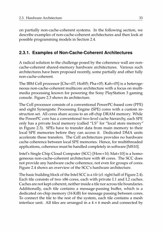
2.3. Hardware Architecture 33
on partially non-cache-coherent systems. In the following section, wedescribe examples of non-cache-coherent architectures and then look atpossible programming models in Section 2.4.
2.3.1. Examples of Non-Cache-Coherent Architectures
A radical solution to the challenge posed by the coherence wall are non-cache-coherent shared-memory hardware architectures. Various sucharchitectures have been proposed recently, some partially and other fullynon-cache-coherent.
The IBM Cell processor [Che+07; Hof05; Pha+05; Kah+05] is a heteroge-neous non-cache-coherent multicore architecture with a focus on multi-media processing known for powering the Sony PlayStation 3 gamingconsole. Figure 2.3 shows its architecture.
The Cell processor consists of a conventional PowerPC-based core (PPE)and eight Synergistic Processing Engine (SPE) cores with a custom in-struction set. All cores share access to an off-chip DRAM memory. Whilethe PowerPC core has a conventional two-level cache hierarchy, each SPEonly has a private local memory (called “LS” for “local store memory”in Figure 2.3). SPEs have to transfer data from main memory to theirlocal SPE memories before they can access it. Dedicated DMA unitsaccelerate these transfers. The Cell architecture provides no hardwarecache coherence between local SPE memories. Hence, for multithreadedapplications, coherence must be handled completely in software [MS10].
Intel’s Single Chip Cloud Computer (SCC) [How+10; Mat+10] is a homo-geneous non-cache-coherent architecture with 48 cores. The SCC doesnot provide any hardware cache coherence, not even for groups of cores.Figure 2.4 shows an overview of the SCC’s hardware architecture.
The basic building block of the Intel SCC is a tile (cf. right half of Figure 2.4).Each tile consists of two x86 cores, each with private L1 and L2 caches.Caches are not kept coherent, neither inside a tile nor across tile boundaries.Additionally, each tile contains a message-passing buffer, which is adedicated on-chip memory (16 KiB) for message passing between cores.To connect the tile to the rest of the system, each tile contains a meshinterface unit. All tiles are arranged in a 4 × 6 mesh and connected by
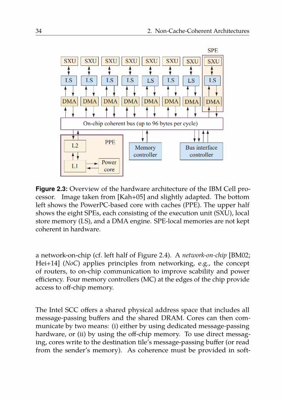
34 2. Non-Cache-Coherent Architectures
Figure 2.3: Overview of the hardware architecture of the IBM Cell pro-cessor. Image taken from [Kah+05] and slightly adapted. The bottomleft shows the PowerPC-based core with caches (PPE). The upper halfshows the eight SPEs, each consisting of the execution unit (SXU), localstore memory (LS), and a DMA engine. SPE-local memories are not keptcoherent in hardware.
a network-on-chip (cf. left half of Figure 2.4). A network-on-chip [BM02;Hei+14] (NoC) applies principles from networking, e.g., the conceptof routers, to on-chip communication to improve scability and powerefficiency. Four memory controllers (MC) at the edges of the chip provideaccess to off-chip memory.
The Intel SCC offers a shared physical address space that includes allmessage-passing buffers and the shared DRAM. Cores can then com-municate by two means: (i) either by using dedicated message-passinghardware, or (ii) by using the off-chip memory. To use direct messag-ing, cores write to the destination tile’s message-passing buffer (or readfrom the sender’s memory). As coherence must be provided in soft-

2.3. Hardware Architecture 35
Figure 2.4: Overview of the hardware architecture of the Intel SCC [Int12].On the left, R denotes NoC routers and MC are memory controllers. Onthe right, MIU stands for “mesh interface unit”, which connects the tileto the NoC. We see that the caches (denoted by “L2”) inside a tile arenot connected to the same bus, as cache coherence does not need to beguaranteed.
ware, the SCC offers dedicated invalidation instructions for use withmessage-passing buffers (we give more details in Section 4.5).
Alternatively, cores can communicate via the shared DRAM. Usually, eachcore of the SCC is assigned a private partition of the off-chip memory,i.e., the hardware enforces that only the owner accesses this partition.However, it is also possible to create memory regions that are sharedbetween cores. By default, these shared regions are marked non-cacheable,thereby avoiding possible coherence-related problems. Consequently,accessing these regions is slow as accesses do not happen at cache-linegranularity but at the granularity of individual loads and stores. However,shared regions can also be marked as cacheable. In this case, the softwarehas to manage coherence. While the SCC does not provide specializedhardware support for this use case, it is still possible to force invalidationsand writebacks [Rot+12].
Intel’s Runnemede [Car+13] is a proposed design of a heterogeneousnon-cache-coherent many-core architecture. Its basic module is the block
(shown in Figure 2.5).
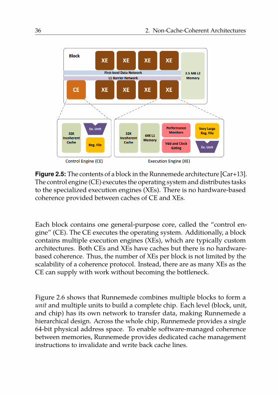
36 2. Non-Cache-Coherent Architectures
Figure 2.5: The contents of a block in the Runnemede architecture [Car+13].The control engine (CE) executes the operating system and distributes tasksto the specialized execution engines (XEs). There is no hardware-basedcoherence provided between caches of CE and XEs.
Each block contains one general-purpose core, called the “control en-gine” (CE). The CE executes the operating system. Additionally, a blockcontains multiple execution engines (XEs), which are typically customarchitectures. Both CEs and XEs have caches but there is no hardware-based coherence. Thus, the number of XEs per block is not limited by thescalability of a coherence protocol. Instead, there are as many XEs as theCE can supply with work without becoming the bottleneck.
Figure 2.6 shows that Runnemede combines multiple blocks to form aunit and multiple units to build a complete chip. Each level (block, unit,and chip) has its own network to transfer data, making Runnemede ahierarchical design. Across the whole chip, Runnemede provides a single64-bit physical address space. To enable software-managed coherencebetween memories, Runnemede provides dedicated cache managementinstructions to invalidate and write back cache lines.
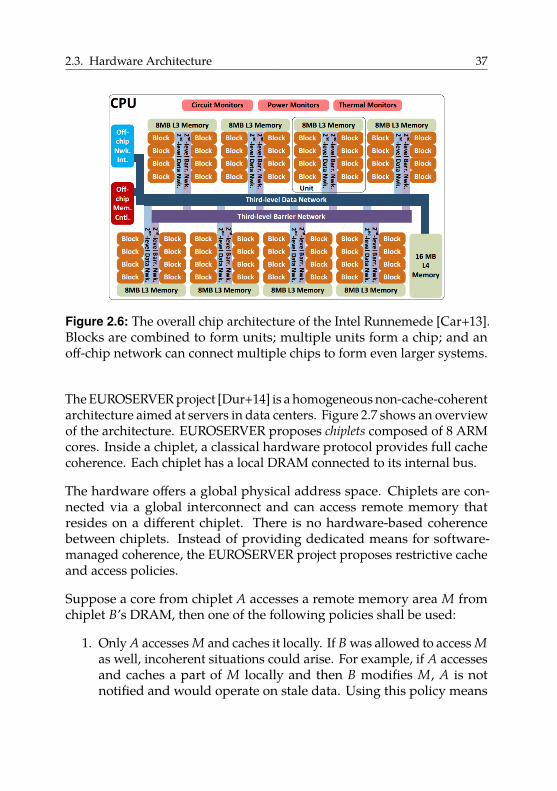
2.3. Hardware Architecture 37
Figure 2.6: The overall chip architecture of the Intel Runnemede [Car+13].Blocks are combined to form units; multiple units form a chip; and anoff-chip network can connect multiple chips to form even larger systems.
The EUROSERVER project [Dur+14] is a homogeneous non-cache-coherentarchitecture aimed at servers in data centers. Figure 2.7 shows an overviewof the architecture. EUROSERVER proposes chiplets composed of 8 ARMcores. Inside a chiplet, a classical hardware protocol provides full cachecoherence. Each chiplet has a local DRAM connected to its internal bus.
The hardware offers a global physical address space. Chiplets are con-nected via a global interconnect and can access remote memory thatresides on a different chiplet. There is no hardware-based coherencebetween chiplets. Instead of providing dedicated means for software-managed coherence, the EUROSERVER project proposes restrictive cacheand access policies.
Suppose a core from chiplet A accesses a remote memory area M fromchiplet B’s DRAM, then one of the following policies shall be used:
1. Only A accesses M and caches it locally. If B was allowed to access Mas well, incoherent situations could arise. For example, if A accessesand caches a part of M locally and then B modifies M, A is notnotified and would operate on stale data. Using this policy means
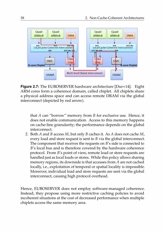
38 2. Non-Cache-Coherent Architectures
Figure 2.7: The EUROSERVER hardware architecture [Dur+14]. EightARM cores form a coherence domain, called chiplet. All chiplets sharea physical address space and can access remote DRAM via the globalinterconnect (depicted by red arrow).
that A can “borrow” memory from B for exclusive use. Hence, itdoes not enable communication. Access to this memory happenson cache-line granularity; the performance depends on the globalinterconnect.
2. Both A and B access M, but only B caches it. As A does not cache M,every load and store request is sent to B via the global interconnect.The component that receives the requests on B’s side is connected toB’s local bus and is therefore covered by the hardware coherenceprotocol. From B’s point of view, remote load or store requests arehandled just as local loads or stores. While this policy allows sharingmemory regions, its downside is that accesses from A are not cachedlocally, i.e., exploitation of temporal or spatial locality is impossible.Moreover, individual load and store requests are sent via the globalinterconnect, causing high protocol overhead.
Hence, EUROSERVER does not employ software-managed coherence.Instead, they propose using more restrictive caching policies to avoidincoherent situations at the cost of decreased performance when multiplechiplets access the same memory area.
2.3. Hardware Architecture 39
The Formic Cube [Lyb+12a; Lyb+16] is a non-cache-coherent many-corearchitecture with 520 cores in total. The system has 8 fast ARM-basedcores and 512 slower Xilinx MicroBlaze cores. The 512 slower cores arearranged in a 3D mesh. Each CPU has a full private cache hierarchy (L1and L2 cache) but the caches are not kept fully coherent. Specifically,there is no hardware-based coherence between the L2 caches of the slowerMicroBlaze cores. The application itself runs on the MicroBlaze cores,while the ARM cores execute a runtime system. The runtime systemmanages coherence between caches in software.
The OpenPiton project [Bal+16] presents an open-source many-core pro-cessor that allows building architectures with up to 500 million cores. Toscale to such core counts, Fu et al. [FNW15] advocate the use of coherencedomain restriction (CDR). CDR is based on the observation that the ma-jority of cache lines are only shared by a small subset of cores, e.g., thosebelonging to a particular application. Hence, CDR restricts coherence tothe level of applications or pages. While this requires additional hardwaresupport, existing directory coherence protocols can be adapted to workwith CDR and Fu et al. demonstrate good scalability.
Current graphics processor unit (GPU) architectures can also be considerednon-cache-coherent architectures. They allow accessing shared memorybut require disabling core-private caches if memory operations shouldbe visible across more than one core [Sin+13]. Disabling caches avoidsincoherent situations but lowers performance significantly. Moreover,there are heterogeneous systems composed of a combination of CPUs andGPUs that provide shared memory between CPU and GPU. By default,these systems do not implement hardware-based coherence between thecaches of CPU and GPU.
For both pure GPU and mixed CPU-GPU systems, there has been work onproviding hardware-based cache coherence [Sin+13; Pow+13]. However,existing coherence protocols do not scale to the core count and memorybandwidth of GPUs. Therefore, Power et al. [Pow+13] employ regioncoherence to manage coherence at a coarser granularity than individualcache lines. Basu et al. [Bas+16] argue that these proposed changes arehard to adopt due to their complexity. Instead, they suggest a hybridsoftware-hardware mechanism that exploits the semantic knowledge by
40 2. Non-Cache-Coherent Architectures
system software (operating system or runtime system) to use hardwarecoherence only when needed.
The Intel Xeon Phi processor [Chr14] is a fully cache-coherent many-corearchitecture providing up to 72 cores. Christgau et al. [CS16] point out thatthe second-generation Xeon Phi processor (codename “Knight’s Landing”)may not be used in a multi-socket system that combines multiple XeonPhi processors. They report that Intel restricted this use case as thecoherence traffic between the processors would exceed the capabilitiesof the interconnect. The Xeon Phi can also be used as a coprocessor, e.g.,in the form factor as a PCIe extension card. In such a configuration, theXeon Phi runs alongside the regular system processor. Each processorcan remotely access the other processor’s main memory, but there is nohardware-based coherence [Bar+15]. Thus, the overall system has twocoherence domains and coherence must be managed in software.
Hence, we have seen that a wide range of diverse many-core architecturesreach the scalability limits of hardware-based cache coherence.
2.4. Programming Model
We now have a detailed understanding of the hardware structure of non-cache-coherent architectures: they still offer a shared physical addressspace; however, not all caches in the system are kept coherent by thehardware. Instead, the systems aim to improve scalability by only offeringcoherence islands of varying size, ranging from just one core to a few,e.g., four or eight. This raises the question of how to program thesemachines.
In the following, we will look at different programming models andinvestigate the work required by compiler and runtime system to bridgethe gap between the guarantees expected by the programmer using aparticular programming model and the guarantees provided by non-cache-coherent shared-memory machines.
First, we will briefly discuss what a programming model is and howit relates to the underlying hardware. Then, we will discuss the use
2.4. Programming Model 41
of the following programming models on non-cache-coherent shared-memory architectures: (i) the shared-memory programming model, (ii) themessage-passing programming model, and (iii) the partitioned globaladdress space (PGAS) programming model.
2.4.1. Parallel Programming Models
A parallel programming model is an abstraction of a parallel computersystem architecture [MSM04; Bar16]. This model governs which toolsprogrammers can use to express their algorithms. The two most importantparallel programming models are the shared-memory model and themessage-passing model.
In the shared-memory model, processes or threads share a commonaddress space, which they read from and write to. Threads communicateby exchanging data via this common address space. Access to shared datais controlled using synchronization mechanisms, such as locks.
In the message-passing model, processes do not share a common addressspace. Instead, they communicate by sending and receiving messages.Usually, transferring data requires cooperation between sender and re-ceiver, i.e., a send operation must have a matching receive operation.
Figure 2.8 shows an abstract view of the shared-memory programmingmodel (Figure 2.8a) and the message-passing model (Figure 2.8b). Circlesdenote execution contexts (threads or processes), rectangles denote ad-dress spaces, dashed arrows denote memory accesses or communicationoperations, and solid arrows represent pointers. We see that in the shared-memory model, multiple threads operate on a shared uniform addressspace. In the message-passing model, we have completely separatedaddress spaces and processes communicate via messages.
This looks very similar to the types of hardware architectures presentedin Section 2.1. However, as programming models are an abstraction abovehardware architecture, they are not tied to particular hardware capabilities.Theoretically, every programming model can be implemented on anyunderlying hardware. As examples, we sketch how we can implementthe shared-memory model and the message-passing model on hardwarearchitectures that suggest a different model.
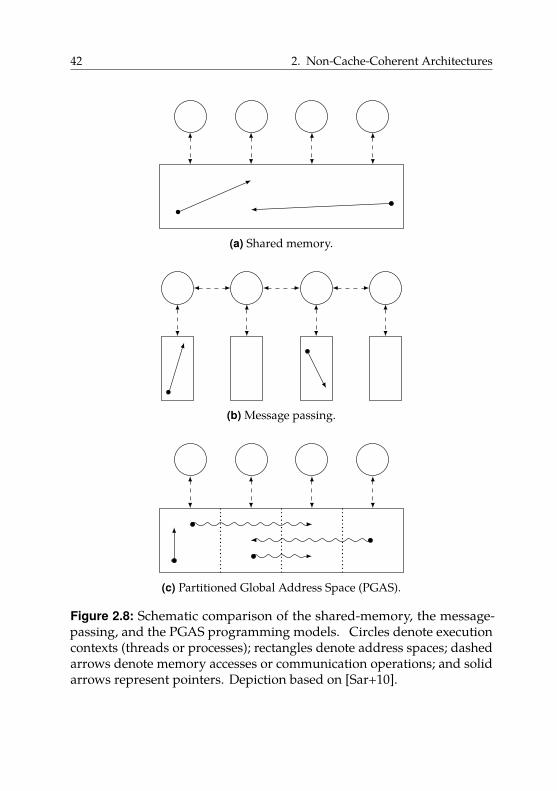
42 2. Non-Cache-Coherent Architectures
(a) Shared memory.
(b) Message passing.
(c) Partitioned Global Address Space (PGAS).
Figure 2.8: Schematic comparison of the shared-memory, the message-passing, and the PGAS programming models. Circles denote executioncontexts (threads or processes); rectangles denote address spaces; dashedarrows denote memory accesses or communication operations; and solidarrows represent pointers. Depiction based on [Sar+10].
2.4. Programming Model 43
We can easily realize a message-passing programming model on top ofa shared-memory system. We can implement the primitives send() andreceive() using write and read operations to the shared address spacecombined with appropriate synchronization. In fact, this is what manyMPI implementations do internally when they are used on a shared-memory machine, such as a regular desktop computer.
Vice versa, we can also realize a shared-memory programming model ontop of message-passing-based hardware. This technique is also knownas software distributed shared memory (software DSM) [NL91]. Thefundamental idea is to provide the illusion of a shared address space byhiding the required message passing. When accessing a piece of datathat is physically located in a remote memory, some layer beneath theprogramming model triggers the required message(s) to fetch the dataitem and mediates access to it. This management can, for example, beperformed by libraries or by the compiler. In both cases, references to dataitems actually consist of two parts: a description of the location of the dataitem (i.e., the number of the owning core) and the actual address that isonly valid at the remote site.
In practice, not every programming model is a good fit for a particularhardware architecture and the overhead of choosing an unsuitable modelmay be high. Therefore, it is important to determine the cost of using aparticular programming model on non-cache-coherent architectures asdescribed in Section 2.3.
2.4.2. Shared-Memory Programming Model
As non-cache-coherent architectures provide a shared physical addressspace, it seems intuitive to continue using a shared-memory programmingmodel. However, using this programming model is not directly possible.As described in Section 2.2, most memory model implementations exploitcache coherence by assuming a coherent memory system. This meansthat when mapping the memory model of the programming languageto the memory model provided by the hardware, compilers assume acoherent memory system. Hence, if we run code generated assumingthese guarantees on a hardware platform that does not implement cachecoherence itself, the program will most likely not work as expected.
44 2. Non-Cache-Coherent Architectures
Thus, if we want to keep the familiar shared-memory programming modelfor the programmer, we must compensate for the missing hardware-basedcache coherence on a level above the hardware, but below the programminglanguage. Hence, either (i) the compiler, (ii) a runtime system or library,or (iii) the operating system must provide coherence.
In the following, we will give an overview of recent work in these areas. Asmentioned in Section 2.2.2.3, software-managed coherence in general andcompiler-managed coherence in particular was a field of active research inthe 1980s and 1990s. We refer to [Ste90] and [TM97] for an overview of thisearly work. As hardware-based coherence became the standard, interestin software-based alternatives declined. In the context of this dissertation,we focus on the more recent work conducted due to the architecturaltrends described in Section 2.3.
Compiler-based approaches. McIlroy et al. [MS10] and Zakkak et al. [ZP16b;ZP16a] present Java virtual machines (JVMs) that can execute standardparallel Java programs on architectures without hardware-based cachecoherence. McIlroy et al. describe Hera-JVM, which targets the Cell ar-chitecture; Zakkak et al.’s implementation, DiSquawk, targets the FormicCube (both architectures are described in Section 2.3.1). In both cases,the Java virtual machine ensures coherence by explicitly triggering cacheactions when necessary.
As mentioned in Section 2.2.2.3, triggering cache actions, i.e., invalidationsand writebacks, too conservatively decreases performance considerably.The extreme case of writing back dirty data after every write and invali-dating cached data before every read is correct but effectively disables thesystem’s caches. Therefore, both JVMs mentioned above exploit the guar-antees provided by the Java memory model [Gos+14, §17] [MPA05; Loc12]to reduce the number of required cache invalidations and writebacks. Inthe following, we use these JVMs as case studies for compiler-based (orVM-based) coherence based on a well-studied memory model.
The Java memory model (JMM) is built upon the notion of the happens-
before relationship. The happens-before relation is a partial order. Certainactions, such as synchronization operations like acquiring and releasinga lock or accessing a volatile field, impose a happens-before order on
2.4. Programming Model 45
program execution. More formally, following Gosling et al. [Gos+14,§17.4.5], we define the relation on actions that are part of an executiontrace (see also Section 2.2.1). We say that a read action r of a variable v isallowed to observe a write action w to v if, in the happens-before partialorder of the execution trace, (i) r does not happen before w, and (ii) thereis no intervening write action w′ to v, i.e., no w′ so that w happens-beforew′.
Practically speaking, this definition means that updates to heap objectscan stay local to a thread, i.e., with values not visible to other threads,until the next synchronization point. Only then must changes becomevisible to other threads. For example, suppose a thread acquires a lockand changes some non-volatile fields, then these updates do not need tobecome immediately visible to other threads.
In terms of the formal definition, the write by the modifying thread and thereads by other threads are not ordered with respect to the happens-beforerelation. Only before releasing the lock must the thread make sure thatall updates it has made are visible to any other thread that later acquiresthe same lock. The synchronization operations (acquiring and releasing),together with the order of the operations in the program, enforce ahappens-before relationship. Hence, reads following an acquisition of thelock must be able to observe the changes made by other threads precedingtheir release of the lock (assuming no intervening writes).
On regular platforms, JVM implementations usually exploit these guar-antees by holding updated values of heap objects in machine registers.They only perform potentially costly write operations to memory whenrequired by the JMM, e.g., when releasing a lock. From the compiler’sor virtual machine’s perspective, synchronization operations restrict themobility of certain memory-related actions. For example, the JMM forbidsreordering a write followed by a release operation in the program, i.e., itis illegal to move the write after the release operation. Depending on thehardware memory model, JVMs may also need to issue memory-barrierinstructions (also called memory fences) to prevent the hardware fromperforming illegal reorderings. See [How+16] and [BA08] for details onmemory barriers.
On a non-cache-coherent architecture, synchronization operations mustadditionally trigger explicit cache operations. As described above, a
46 2. Non-Cache-Coherent Architectures
thread acquiring a lock must be able to observe updates to the sharedheap performed by another thread that held and released the same lockbefore. Thus, the JVM implementation of McIlroy et al. writes back andthen invalidates the complete data cache whenever the current threadacquires a lock or reads a volatile field [MS10, section 5.3]. Before releasinga lock or writing to a volatile field, the implementation issues a writebackof the complete cache to make the changes visible to other threads. TheHera-JVM also performs explicit cache actions in other situations, such ascontext switches. Similarly, the DiSquawk JVM writes back and invalidates,i.e., flushes, any cached data before volatile accesses, and writes backdirty cached data directly after writes to volatile variables [ZP16b, section3.3].
This raises the question of precisely characterizing the locations thatrequire such cache actions. To this end, Zakkak et al. [ZP14] present theJDMM, the Java Distributed Memory Model, a formalization of the JMMfor non-cache-coherent architectures. The JDMM extends the JMM withadditional cache-related actions, in particular writeback and invalidation.Zakkak et al. then show that the JDMM adheres to the JMM. However, theirformalization is not machine-checked. See [Loc12] for a machine-checkedformalization of the JMM.
Tavarageri et al. [Tav+16] present a compiler-assisted approach for in-serting necessary cache-coherence instructions into parallel programs.Their modified compiler inserts writeback and invalidation instructionsas presented in Section 2.2.2.3. To avoid false-sharing problems, theirapproach requires per-word dirty bits for each cache line, which increaseshardware overhead.
Tavarageri et al. differentiate between regular code, where control flowand data flow are known at compile time (mostly well-formed loops), andirregular code. For regular code, they use the polyhedral model [Bas04] toprecisely identify locations for cache actions. For irregular code, they fallback to more conservative approximations, with invalidation or writebackof the complete cache as a last resort. Hence, their baseline approach issimilar to the previously presented JVM-based approaches, however, theycan exploit a more regular program structure to improve the precision ofcoherence actions.
2.4. Programming Model 47
Library-based approaches. Library-based approaches implement a soft-ware DSM system (see Section 2.4.1) on top of non-coherent sharedmemory. We refer to [Nür+14] for an overview of software DSM systemsin the context of many-core architectures.
Prescher et al. [PRN11; Rot+12] implement library-based DSM for theIntel SCC. Their C++ library offers smart pointers that, in addition to theactual object address, save information required for cache management.Specifically, these smart pointers refer to consistency controller objects thatmanage the necessary invalidations and writebacks.
To avoid too frequent coherence actions, the smart pointers do not actuallyallow accessing the underlying shared object. Instead, the user has tocreate access-proxy objects that grant either read-only or exclusive writeaccess. The actual cache operations are triggered on object constructionand destruction of the access proxies.
Their library offers multiple strategies for coherence management. Thesimplest one uses one needs-invalidate flag on each core for each sharedobject. This flag signifies if another core has changed the shared object,which must therefore be fetched from main memory.
For example, when acquiring write access to a shared object by creatingthe matching access-proxy object, the consistency controller checks thelocal needs-invalidate flag. If it is set, the controller invalidates the sharedobject’s memory range in the local cache. All subsequent accesses thencause cache misses and thus the up-to-date version of the shared objectis fetched from main memory. After the core is done working with theobject, it destroys the access proxy. The destruction triggers a writeback ofthe dirty data in the cache and at the same time sets the needs-invalidateflag on all other cores.
In comparison to the previously presented compiler-based approaches,this enables shared-memory programming on a much lower level. Theprogrammer must be actively aware of the non-cache-coherent memoryand must manage shared objects with the provided smart pointers andaccess proxies. If the programmer accesses a shared object using rawpointers, no coherence actions are triggered, potentially leading to subtlebugs. In summary, the proposed library-based software-DSM system is
48 2. Non-Cache-Coherent Architectures
more flexible and potentially more efficient with the downside that itrequires changes to the source program and is unsafe.
Operating-system-based approaches. Multiple projects modify Linuxto run on non-cache-coherent architectures, while differing in their im-plementation details. For example, K2 [LWZ14] targets mobile systems-on-chip that consist of multiple but few, i.e., two or three, heterogeneouscoherence domains. Popcorn [Bar+15] modifies Linux to run on platformsconsisting of multiple OS-capable multi-core processors with differentISAs, such as a regular x86 multi-core extended with a PCIe-based IntelXeon Phi processor.
Both operating systems provide transparent coherence via distributedshared memory implemented by managing coherence in software at pagegranularity. The key idea is to maintain the invariant that there is onlyone writer per memory page (typically of size 4 KiB). For example, K2maintains a simple state flag, valid or invalid, per page and core. A simpleprotocol then ensures that at each point in time, each page is only valid onat most one core.
This protocol works as follows. A core can read or write a locally validpage. However, accessing a locally invalid page triggers a page fault.The page-fault handler notifies the current owner of the respective pageto flush the page from the owner’s cache to memory and then give upownership by setting the local state of the page to invalid. Then, the corethat caused the page fault becomes the new owner of the page, i.e., thepage is now locally in the valid state and can be accessed by the core.
These approaches manage coherence in software on a level below the codegenerated by compilers. Hence, it is possible to reuse existing compilersand generated binaries that expect coherent shared memory. However,the granularity of coherence is coarse (whole pages), which can lowerperformance significantly depending on the access behavior.
Overall, we see that using the shared-memory programming model onnon-cache-coherent many-core architectures is feasible. The necessarycache actions can be managed by a library or runtime system, by thecompiler, or by the operating system. For the latter two, we do not need toadapt the code of existing parallel applications; for the last, even compilerscan stay unchanged.
2.4. Programming Model 49
2.4.3. Message Passing
In the previous section we have seen how we can program a non-cache-coherent shared-memory machine using the shared-memory program-ming model. However, different programming models can be used as well.In the following, we look at the message-passing programming model inmore detail.
As explained in Section 2.1, message passing is commonly used onmachines that do not provide a shared physical address space, i.e., providefewer capabilities than shared-memory machines. Therefore, it is notsurprising that we can easily use message passing also on non-cache-coherent shared-memory machines.
The fundamental idea, shown in Figure 2.9, is to partition the sharedaddress space and assign each partition to one coherence domain. Thiscoherence domain is the sole owner of this part of the address space.Hence, only cores from the owning coherence domain access the respectiveaddress-space partition.
The cores may also have caches that cache memory contents from thispartition. As the caches inside a coherence domain are coherent bydefinition, accesses to the same address by multiple cores from the samedomain (if domains contain more than one core) do not cause problems.On the other hand, due to the partitioning of the address space, coresfrom separate domains never access a common address. Hence, we do notneed global cache coherence. The address space partitioning happens ona logical level, for example in the programming model, i.e., by preventingthe creation of pointers to foreign memory partitions in the programminglanguage, or in the operating system, i.e., by not mapping foreign memorypartitions into a domain’s virtual address space.
Fundamentally, we hide the fact that the hardware actually providesa shared physical address space from the programmer. We disallowproblematic memory accesses, i.e., to the same address from differentcoherence domains, on a logical level. By doing this, we shield theprogrammer from coherence-related problems.
This raises the question of how communication between coherence do-mains actually happens, i.e., how we implement the primitive operations
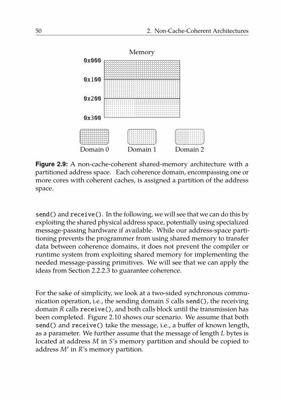
50 2. Non-Cache-Coherent Architectures
Domain 0 Domain 1 Domain 2
Memory0x000
0x100
0x200
0x300
Figure 2.9: A non-cache-coherent shared-memory architecture with apartitioned address space. Each coherence domain, encompassing one ormore cores with coherent caches, is assigned a partition of the addressspace.
send() and receive(). In the following, we will see that we can do this byexploiting the shared physical address space, potentially using specializedmessage-passing hardware if available. While our address-space parti-tioning prevents the programmer from using shared memory to transferdata between coherence domains, it does not prevent the compiler orruntime system from exploiting shared memory for implementing theneeded message-passing primitives. We will see that we can apply theideas from Section 2.2.2.3 to guarantee coherence.
For the sake of simplicity, we look at a two-sided synchronous commu-nication operation, i.e., the sending domain S calls send(), the receivingdomain R calls receive(), and both calls block until the transmission hasbeen completed. Figure 2.10 shows our scenario. We assume that bothsend() and receive() take the message, i.e., a buffer of known length,as a parameter. We further assume that the message of length L bytes islocated at address M in S’s memory partition and should be copied toaddress M′ in R’s memory partition.
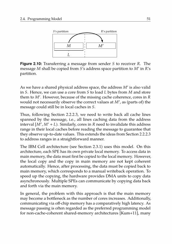
2.4. Programming Model 51
M
L
M′
S’s partition R’s partition
Figure 2.10: Transferring a message from sender S to receiver R. Themessage M shall be copied from S’s address space partition to M′ in R’spartition.
As we have a shared physical address space, the address M′ is also validin S. Hence, we can use a core from S to load L bytes from M and storethem to M′. However, because of the missing cache coherence, cores in Rwould not necessarily observe the correct values at M′, as (parts of) themessage could still be in local caches in S.
Thus, following Section 2.2.2.3, we need to write back all cache linesspanned by the message, i.e., all lines caching data from the addressinterval [M′,M′ + L). Similarly, cores in R need to invalidate this addressrange in their local caches before reading the message to guarantee thatthey observe up-to-date values. This extends the ideas from Section 2.2.2.3to address ranges in a straightforward manner.
The IBM Cell architecture (see Section 2.3.1) uses this model. On thisarchitecture, each SPE has its own private local memory. To access data inmain memory, the data must first be copied to the local memory. However,the local copy and the copy in main memory are not kept coherentautomatically. Hence, after processing, the data must be copied back tomain memory, which corresponds to a manual writeback operation. Tospeed up the copying, the hardware provides DMA units to copy dataasynchronously. Multiple SPEs can communicate by copying data backand forth via the main memory.
In general, the problem with this approach is that the main memorymay become a bottleneck as the number of cores increases. Additionally,communicating via off-chip memory has a comparatively high latency. Asmessage passing is often regarded as the preferred programming modelfor non-cache-coherent shared-memory architectures [Kum+11], many
52 2. Non-Cache-Coherent Architectures
of them provide additional memories dedicated to message passing thatenable a more decentralized form of communication with significantlylower latency.
The idea is that each coherence domain has a small but fast on-chipmemory that is visible in the global physical address space. Hence,we can implement send() by having the sender execute regular storesto the on-chip memory of the receiving domain; or, alternatively, byhaving the receiver execute regular loads from the on-chip memory of thesending domain. Thus, we omit using the off-chip main memory for everycommunication operation. For performance reasons, writes to remoteon-chip memories are often cached as well. In this case, we have to managecoherence in software just as described above. We extensively discuss datatransfers and their performance characteristics on non-cache-coherentarchitectures in Section 4.3.
As a concrete example, the Intel SCC provides message-passing buffers(MPBs, see Figure 2.4) [Mat+10, section III]. These MPBs are small (16 KiB)fast on-chip memories dedicated to direct communication between cores.Cores can load from and store to local and remote MPBs. Data from MPBsis cached in the L1 cache and the SCC provides a dedicated instructionfor software-managed coherence of MPBs. We refer to Mattson et al.’sdescription [Mat+10, section V] for details. We also discuss this topic inSection 4.5.
Similarly, the Runnemede platform provides on-chip scratchpads that arepart of the global address space. Additionally, it provides DMA units toaccelerate data transfers. The hardware provides dedicated invalidationand writeback instructions. The Formic Cube uses the same approach.Additionally, it offers a faster message operation for very small transfers(a single 32-bit word).
We see that while the message-passing model does not expose sharedmemory to the programmer, the actual implementation of message-passingprimitives exploits the physical address space of non-cache-coherentarchitectures and manages coherence in software.
2.4. Programming Model 53
2.4.4. The PGAS Model
The Partitioned Global Address Space (PGAS) model [Alm11; Sar+10; De+15] extends the shared-memory programming model to better handlethe presence of distributed memory.
The fundamental observation is that shared-memory programming worksworse as the cost of accessing remote data items increases. The differentcosts of local and remote memory accesses are often summarized by the“NUMA factor” in the literature (cf. NUMA architectures introduced inSection 2.1). The NUMA factor is the ratio of the cost of a remote memoryaccess and the local memory access cost. Hence, a NUMA factor of 2means a 2× slowdown when accessing remote data items.
Shared-memory programming works well if the NUMA factor is relativelylow. However, as the NUMA factor grows, the illusion of a uniformaddress space becomes increasingly unrealistic as some data items aremuch more costly to access. At the same time, all data items and referenceslook the same to the programmer, whether local or remote. This inabilityto reflect the properties of the underlying hardware can lower performancesignificantly, e.g., when accidentally accessing remote memory.
To counter this problem, the PGAS model adds a notion of data locality tothe shared-memory programming model. Here, the programmer can andmust explicitly manage the location of each piece of data. Additionally,references to local data items are explicitly distinguishable from referencesto remote data items, e.g., by having a different type.
However, unlike the message-passing model, the PGAS model still offersa global address space. This means that every process can point to everymemory location, even if it is physically located in a remote memory. Yet,in contrast to the pure shared-memory model, now the notion of near andfar memory is explicit, i.e., the address space is partitioned.
Figure 2.8 shows a schematic comparison of the shared-memory, themessage-passing, and the PGAS programming models. We see that in ashared-memory model, as explained in Section 2.4.1, multiple threads runinside the same uniform address space. Every thread can have referencesto data items created by other threads. In a message-passing model, weexpress a computation using multiple processes with private address
54 2. Non-Cache-Coherent Architectures
spaces that exchange data via messages. It is impossible for one processto reference data from another process; the address spaces are strictlyseparated. In the PGAS model, the address space of multiple processes isunified, as with the shared-memory model. However, the address spaceis not uniform; instead, it is partitioned to reflect the location of data items.Figure 2.8c uses different arrow types for references to local and remotedata items, respectively.
Additionally, the PGAS model makes communication partially implicit.Accessing remote data items usually happens via simple assignment ordereference operations. Hence, the programmer does not have to explicitlyinsert communication operations, such as send() and receive() withmessage passing, into their program. Instead, it is the task of compilerand runtime system to perform the necessary communication to accessa remote data item, e.g., exchanging messages on a hardware platformwithout a shared physical address space.
These properties make the PGAS model attractive to use on non-cache-coherent shared-memory machines. As such hardware offers a sharedphysical address space, shared-memory programming seems like a goodfit in principle. However, the cost of accessing data from other coherencedomains may be high due to the required communication, e.g., dueto software-managed coherence. This makes the illusion of a uniformaddress space hard to maintain, which is exactly the problem tackled bythe PGAS model.
Hence, the PGAS model maps naturally to non-cache-coherent architec-tures: we interpret locality not in terms of physical memory location butregarding coherence domains5. Thus, we first partition the address spaceas shown in Figure 2.9. Then, from the view of a coherence domain, localdata items reside in the domain’s own memory partition while remotedata items reside in foreign memory partitions associated with othercoherence domains.
The programmer still has most of the benefits of shared-memory program-ming, e.g., a global address space. However, at the same time, they are
5The physical memory location may (and for performance reasons should) coincide withcoherence boundaries. Imagine a system like Figure 2.1b with a shared physical addressspace but no hardware-based coherence. Then, a coherence domain consists of a corewith its (physically) local memory.
2.4. Programming Model 55
aware of potentially costly accesses to remote data from other coherencedomains as locality is exposed in the programming model.
The PGAS programming model does not specify a particular implemen-tation of remote data access. On message-passing hardware without ashared physical address space, accessing a remote data item triggers thesending of one or more messages. On non-cache-coherent architectures,we can therefore reuse the techniques from Section 2.4.3 to implement therequired communication.
However, PGAS runtime systems usually prefer so-called one-sided com-munication [Mes15, chapter 11]. Here, one party specifies all necessarycommunication parameters, both for the sending side and the receivingside. Hence, on a non-cache-coherent architecture, a PGAS runtimesystem can be implemented using a message-passing mechanism. Itspreferred mode of operation is, however, one-sided, which we can imple-ment using explicit writebacks and invalidations on non-cache-coherentsystems [CS16; CS17]. We discuss this in detail in Section 4.3.
We see that the PGAS programming model is a good candidate for use onnon-cache-coherent architectures. By making the address space unified, itmaintains many of the programmability advantages of the shared-memorymodel. By making the address space non-uniform, it exposes more ofthe hardware, in particular the existence of multiple coherence domains,which may improve performance. Moreover, implicit communicationoperations instead of explicit messaging operations reduce programmerburden.
56 2. Non-Cache-Coherent Architectures
Summary
• Coherence is a property of a system guaranteeing that thepresence of caches never enables new or different functionalbehavior.
• Coherence can be maintained by hardware or software.
• A non-cache-coherent shared-memory system offers a sharedphysical address space but no hardware-based coherence.
• Multiple non-cache-coherent systems have been built or pro-posed for power and scalability reasons. They differ in thenumber and size of their coherence domains.
• Efficient implementation of the shared-memory programmingmodel requires hardware support for fine-grained cache controlto enable software-based coherence.
• Libraries, operating systems, or compilers can manage coherencein software.
• Efficient implementation of message passing benefits from faston-chip memories.
• Both the message-passing and the PGAS programming modelbenefit from hardware support for coarse-grained software-managed coherence.
What is usually meant by the term craftsmanship is
the production of things of high quality; Ruskin makes
the crucial point that a thing may also be judged
according to the conditions under which it was built.
Tracy Kidder, The Soul of a New Machine, p. 272
3Invasive Computing
While the work presented in this dissertation is generally applicable tomodern parallel architectures, the prototype implementations presentedin Chapters 4 and 5 make heavy use of infrastructure developed in thecontext of the research project Invasive Computing [Tei+11; Tei+16]. Thisproject investigates ways to improve the efficiency and predictability ofresource usage on future many-core systems using a holistic approach thattakes into account every system component, i.e., ranging from low-levelhardware to high-level software.
In the following sections, we start by introducing the reader to the overallidea of Invasive Computing in an abstract way. Then, we provide abottom-up view of the project starting from the hardware and thencovering components such as system software, programming language,and compiler. We relate each component to the recent developments inthe context of many-core architectures presented in Chapter 2. While wecover most parts of the invasive ecosystem, we describe in detail only theaspects relevant in the context of this dissertation. For details on otheraspects, we refer the interested reader to the referenced material.
57
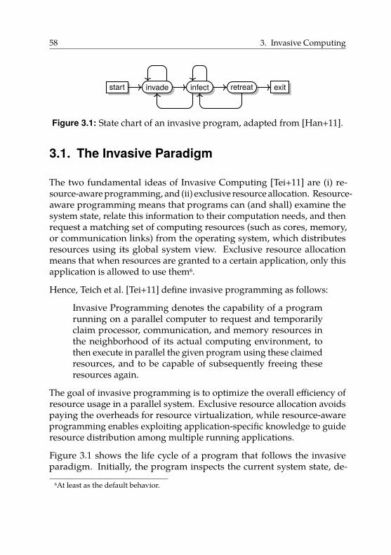
58 3. Invasive Computing
start invade infect retreat exit
Figure 3.1: State chart of an invasive program, adapted from [Han+11].
3.1. The Invasive Paradigm
The two fundamental ideas of Invasive Computing [Tei+11] are (i) re-source-aware programming, and (ii) exclusive resource allocation. Resource-aware programming means that programs can (and shall) examine thesystem state, relate this information to their computation needs, and thenrequest a matching set of computing resources (such as cores, memory,or communication links) from the operating system, which distributesresources using its global system view. Exclusive resource allocationmeans that when resources are granted to a certain application, only thisapplication is allowed to use them6.
Hence, Teich et al. [Tei+11] define invasive programming as follows:
Invasive Programming denotes the capability of a programrunning on a parallel computer to request and temporarilyclaim processor, communication, and memory resources inthe neighborhood of its actual computing environment, tothen execute in parallel the given program using these claimedresources, and to be capable of subsequently freeing theseresources again.
The goal of invasive programming is to optimize the overall efficiency ofresource usage in a parallel system. Exclusive resource allocation avoidspaying the overheads for resource virtualization, while resource-awareprogramming enables exploiting application-specific knowledge to guideresource distribution among multiple running applications.
Figure 3.1 shows the life cycle of a program that follows the invasiveparadigm. Initially, the program inspects the current system state, de-
6At least as the default behavior.
3.1. The Invasive Paradigm 59
termines a sensible set of initial resources, and then issues a resourcerequest, called invade, to the system. If the request is granted, the systemresponds with a claim that contains resources exclusively allocated to theapplication. The program then uses these newly claimed resources in aphase called infect.
Every time the program reaches a point where it is possible and sensibleto adapt its set of resources, the program should inform the system. Theprogram may do that using retreat, which releases the claim’s resources,or using (re-)invade, which potentially changes the claim and enables thesystem to redistribute resources. Following the resource-aware paradigm,each time a program wants to change its claim it should first analyzethe system state, figure out a sensible resource change, and then send arequest to the system via (re-)invade. Once a program retreats from all itsclaims, it terminates execution and exits.
Programs formulate resource requests in a sophisticated constraint lan-guage [ZBS13]. The language allows expressing multiple alternativeresource requests (using a logical-or construct) and ranges (e.g., request-ing 1 to 10 cores). Hence, granting a resource request is not necessarilya binary decision. Additionally, constraints allow passing application-specific knowledge (e.g., about scaling behavior) to the system. Thus, thesystem ideally has many degrees of freedom when distributing resourcesamong multiple running applications. Furthermore, it has the necessaryinformation about applications to make a globally sensible decision. Theactual resource distribution is performed in a decentralized way to ensurescalability [Kob+11].
We can also exploit exclusive resource allocation to optimize for goalsother than efficiency. For example, exclusive allocation enables precisecontrol over interference with other applications. Hence, it can alsosignificantly simplify reasoning about non-functional properties, such astiming predictability [Wil+16].
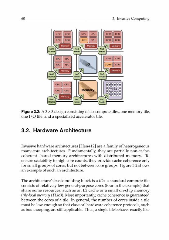
60 3. Invasive Computing
CPU CPU
CPU CPU
Memory
CPU
i-Core CPU
Memory
CPU
CPU CPU
CPU CPU
Memory
MemoryI/O
CPU
i-Core CPU
Memory
CPU
Memory TCPA
CPU CPU
CPU CPU
Memory
CPU CPU
CPU CPU
NoC
Router
NoC
RouterNoC
Router
NoC
Router
NoC
Router
NoC
Router
NoC
RouterNoC
Router
NoC
Router
Memory
Figure 3.2: A 3× 3 design consisting of six compute tiles, one memory tile,one I/O tile, and a specialized accelerator tile.
3.2. Hardware Architecture
Invasive hardware architectures [Hen+12] are a family of heterogeneousmany-core architectures. Fundamentally, they are partially non-cache-coherent shared-memory architectures with distributed memory. Toensure scalability to high core counts, they provide cache coherence onlyfor small groups of cores, but not between core groups. Figure 3.2 showsan example of such an architecture.
The architecture’s basic building block is a tile: a standard compute tileconsists of relatively few general-purpose cores (four in the example) thatshare some resources, such as an L2 cache or a small on-chip memory(tile-local memory (TLM)). Most importantly, cache coherence is guaranteedbetween the cores of a tile. In general, the number of cores inside a tilemust be low enough so that classical hardware coherence protocols, suchas bus snooping, are still applicable. Thus, a single tile behaves exactly like
3.2. Hardware Architecture 61
a common cache-coherent multicore processor and can be programmedusing the traditional shared-memory programming model.
Multiple tiles can be combined to create a larger system. Each tile containsa network adapter [Zai+15] (“NA” in Figure 3.2), which connects the tile toa scalable network-on-chip [Hei+14] (NoC) that transfers data between tiles.However, the hardware provides no cache coherence between differenttiles.
While this improves scalabilty, it raises the question of how to best com-municate between tiles. The designated communication means is messagepassing. To this end, the architecture provides a shared physical addressspace across all tiles. In particular, all tile-local memories are visible.Thus, to send a message, a core stores the data into the receiving tile’sTLM. In this case, coherence must be managed in software (as explainedin Section 2.4.3). Additionally, the NoC and network adapter providehardware-accelerated DMA transfers. DMA transfers asynchronouslycopy a block of data from the sending tile’s TLM to the receiving tile’sTLM (we present more details on DMA transfers in Sections 3.3 and 4.3).
Invasive architectures provide hardware support for important higher-level operations. Inside a tile, a special hardware unit, the Core i-letController (CiC), accelerates scheduling tasks to a tile’s cores [Rav15].Besides improving scheduling and dispatching throughput, the CiC’slatency is low enough to be able to consider various sensor values, suchas power or temperature readings. For example, it can schedule a taskto the coolest core. To simplify and accelerate communication betweentiles, the network adapter provides hardware support for starting tasks onremote tiles [Zai+15]. Network adapter and CiC cooperate closely; theycan schedule and dispatch a newly started task on a remote tile withoutoperating system assistance.
Not all tiles are (pure) compute tiles. Invasive architectures may alsoinclude memory tiles and I/O tiles. Memory tiles are connected to off-chipDRAM, which, in general, holds most of a program’s data. This memoryusually makes up the bulk of the shared physical address space. I/O tilesprovide access to peripheral devices, such as networking. Cores fromother tiles use these resources by accessing them over the NoC.
62 3. Invasive Computing
Furthermore, not all compute resources are homogeneous. Invasivearchitectures may include specialized hardware, both in the form ofindividual specialized cores or whole specialized tiles. An example of theformer is the i-Core [Bau09]. The i-Core consists of a regular core extendedwith an FPGA-based fabric. It allows loading accelerator modules onto theFPGA, which can be used by the core via special instructions exposed asan instruction set extension. The i-Core behaves like a regular core as longas the regular instruction set is used. Applications aware of its capabilitiescan use the special instructions to benefit from hardware acceleration.
Alternatively, complete tiles can be dedicated to accelerators. For ex-ample, such accelerator tiles may contain tightly-coupled processor ar-rays [Han+14] (TCPAs). TCPAs consist of processor elements with adomain-specific instruction set that are arranged in a 2D grid and con-nected by a low-latency network. They are particularly well-suited forcomputationally intensive applications from domains such as image orsignal processing. Accelerator tiles are connected to the rest of the systemvia a regular control processor that is part of the tile (not shown in Fig-ure 3.2). The control processor receives input data, initiates computations,and sends back the results once the computation on the accelerator hascompleted.
3.2.1. Related Work
Invasive architectures are non-cache-coherent shared-memory architec-tures and thus closely related to the architectures described in Sec-tion 2.3.1.
When comparing invasive architectures to the Intel SCC, both share manyproperties: they are tile-based, with multiple cores on each tile sharingsome resources; they employ a network-on-chip as their scalable inter-connect; and they encourage message passing by providing fast tile-localmemory. However, there are also important differences. Unlike invasivearchitectures, the Intel SCC does not guarantee cache coherence inside atile, i.e., it is a fully non-cache-coherent architecture. In contrast, invasivearchitectures are partially cache-coherent. Thus, invasive architecturessuggest a hybrid programming model using shared memory inside a tileand message passing between tiles, while the Intel SCC was designed as
3.3. Operating System 63
a pure message-passing platform. Moreover, the SCC is homogeneous,whereas invasive architectures may contain specialized cores or tiles, usinga different (or extended) instruction set.
When looking at the Intel Runnemede, we find similar commonalitiesand differences. The Runnemede also has a tile-based structure; scalableinterconnects; and fast tile-local memories. In contrast to invasive archi-tectures and the Intel SCC, Runnemede is strongly heterogeneous andasymmetric inside a tile. Here, only one core per tile is capable of runningan operating system and all other cores are specialized accelerators thatpossibly use a different instruction set.
The EUROSERVER architecture is another partially non-cache-coherentarchitecture. In contrast to invasive architectures, EUROSERVER ishomogeneous and has a more uniform memory hierarchy, with oneDRAM module per tile and no on-chip memories. Most importantly,it proposes the use of restrictive caching policies to avoid incoherentsituations. Thus, it does not require software-managed coherence.
3.3. Operating System
As the programming paradigm and the architecture proposed by InvasiveComputing place new demands on the operating system, a novel operatingsystem has been developed in the scope of the research project. OctoPOS[Oec+11; Moh+15] is an operating system designed specifically for non-cache-coherent shared-memory architectures, including the family ofinvasive architectures as described in Section 3.2. The primary designgoal of OctoPOS is to exploit fine-grained parallelism in applicationsdirectly on the operating-system level. Additionally, it integrates resource-distribution functionalities needed for resource-aware programming.
OctoPOS offers an execution model that is more lightweight than thetraditional UNIX model of processes and threads. The principal ideais that the operating system represents parallelizable control flows notas coarse-grained, long-running threads with preemption, but as short
64 3. Invasive Computing
snippets of code called i-lets7. An i-let consists of (i) a pointer to a functionto be executed, and (ii) a piece of data passed as an argument.
A typical parallel application running on top of OctoPOS splits its workinto many packages, creates an i-let for each work package, and hands thesei-lets to the operating system for execution. The OS scheduler distributesthe i-lets to the available CPU cores, where they are processed sequentially.Like user-level threads, i-lets use cooperative scheduling. For i-lets thatrun to completion, creation and dispatching are very efficient becausethe respective execution contexts (i.e., stacks) can simply be reused. TheOS performs a costlier context switch only if an i-let performs a blockingoperation.
Using cooperative scheduling becomes possible by exploiting the exclusiveresource-allocation scheme of Invasive Computing. Following Section 3.1,all resources of an application, including CPUs, belong to its claim.Claims are a central data structure in OctoPOS. The scheduler distributesan application’s i-lets only to CPUs in its claim. Thereby, it enforces spatialseparation of concurrently running applications. Hence, no preemption isnecessary, as applications have full control over their core set anyway.
OctoPOS follows a multikernel design [Bau+09]. On an invasive architec-ture, each tile runs a separate instance of the operating system. Internalstate is replicated on each tile. The instances communicate via messagepassing, e.g., to synchronize the initial system boot process.
Following the hardware/software codesign approach of Invasive Com-puting, the hardware provides dedicated support for i-lets. To this end,the i-let format has been fixed to include a function pointer and two 32-bitdata words. The data words can hold by-value arguments, or pointers incase of larger input data, which is then transmitted separately.
Applications spanning more than one tile, i.e., more than a single coherencedomain, can communicate using the following two OS-level primitives.
Remote i-let spawning. Code execution on a remote tile is triggeredby sending a fixed-size packet containing an i-let over the NoC. On the
7i-let is short for “invasive-let”, inspired by the term “servlet” [Tei+11].
3.3. Operating System 65
receiving side, the i-let is inserted into the regular scheduling queue andexecuted asynchronously to the sender’s control flow.
As this is a frequent operation, OctoPOS can exploit special hardwareprovided by an invasive architecture to accelerate it. In fact, the cooperationbetween NoC and CiC as described in Section 3.2 is based on i-lets. Thus,when the NoC has transmitted an i-let to a remote tile, the network adapterdirectly hands the i-let to the CiC for scheduling and dispatching on thetile’s cores. Following the invasive paradigm from Section 3.1, spawninga remote i-let corresponds to infecting the respective claim.
Push-DMA transfer. To allow transferring larger chunks of data betweentiles, OctoPOS offers a push mechanism that allows copying an arbitrarilylarge contiguous memory region to a buffer in another tile’s local memory.The receiving tile is guaranteed to have a coherent view of the destinationbuffer after the transfer has completed. The operation is performedasynchronously as a DMA transfer, allowing the sending process tocontinue work without blocking. The caller of a push-DMA operation canoptionally pass a pair of i-lets along with the data:
1. The first i-let will be executed on the sending tile once the operationhas completed, and can be used for releasing the source buffer orfor implementing custom blocking if desired.
2. The second i-let will be spawned on the receiving tile, where it canbegin processing the transferred data.
Again, as this is an important and frequent operation, invasive archi-tectures provide special hardware support. After triggering the DMAoperation, the hardware completely handles the data transfer as well asthe dispatching of local and remote i-lets. This is achieved by cooperationof NoC, network adapter, and CiC.
Synchronization. For the synchronization of i-lets, OctoPOS offers alightweight barrier-like concept called signal, which is optimized fora fork-join scenario. The standard pattern in this scenario is one i-letthat spawns multiple other i-lets for parallel work, and then waits fortheir termination. An OctoPOS signal is initialized with a counter value
66 3. Invasive Computing
equal to the number of jobs. After creating the jobs, the spawning i-letinvokes the wait() primitive, which blocks until the counter reaches zero.Each job does its work and afterwards calls signal(), which decrementsthe counter by one. If the number of jobs is not known in advance,add_signalers() can be called for new i-lets created dynamically toincrement the counter.
OctoPOS signals are similar to blocking semaphores, but more lightweight:Only a single i-let per signal is allowed to wait, so there is no need for awaiting queue. Activities that were spawned on another tile can signalback to their original tile by sending an i-let that performs the signaling.
In summary, OctoPOS is an operating system for non-cache-coherentarchitectures that implements a lightweight i-let-based execution modeland offers asynchronous operations for cross-tile data transfers and taskspawning. On invasive architectures, the most important operations areaccelerated by dedicated hardware units.
Resource management. As we allocate resources exclusively, we needa way to adapt the resources of an application to its needs. Otherwise,resources sit idle or applications cannot fully exploit their inherent paral-lelism. Therefore, in Invasive Computing, applications are expected toinform the system of changed resource requirements. To avoid a singlebottleneck, resource management proceeds in a distributed fashion.
Each application is represented by an agent. Every resource request ofan application goes via its agent. Agents communicate in a distributedmanner and bargain for resources [Kob+11]. After the bargaining hasfinished, the agent then notifies the application of the result. The agentsystem is part of the operating system. Together, OctoPOS and the agentsystem form the invasive runtime support system (iRTSS).
3.3.1. Related Work
The Barrelfish operating system [Bau+09] aims into a similar directionas OctoPOS as it pioneered the idea of using multikernels on shared-memory many-core architectures. Hence, as with OctoPOS, multiple OS
3.3. Operating System 67
instances communicate via message passing. The use of Barrelfish onnon-cache-coherent architectures has been investigated using the IntelSCC as a platform [Pet+11b]. Unlike OctoPOS, however, the Barrelfishkernel implements a traditional, heavyweight threading model.
Multiple projects modify Linux to run on non-cache-coherent architectures,while differing in their implementation details. For example, K2 [LWZ14]targets mobile systems-on-chip that consist of multiple but few, i.e., twoor three, heterogeneous coherence domains. K2 also runs one kernel percoherence domain. However, K2 uses a “shared-most” approach thatreplicates most OS services in all coherence domains but maintains statecoherence. K2 provides transparent coherence via distributed sharedmemory (see Section 2.4.1) implemented by managing coherence insoftware at page granularity.
Popcorn [Bar+15] modifies Linux to run on platforms consisting of multipleOS-capable multi-core processors with different ISAs, such as a regularx86 multi-core extended with a PCIe-based Intel Xeon Phi processor. Inthis scenario, the fundamental idea of Popcorn is not to view the Xeon Phias a coprocessor used by offloading but to view both processors as a unit.Popcorn does not assume cache coherence and thus uses replicated OSkernels per coherence domain. In case of missing hardware-based cachecoherence, Popcorn provides software DSM. Other than K2, Popcornfollows the shared-nothing principle.
Unlike OctoPOS, both K2 and Popcorn are designed to execute regularprograms written in a shared-memory style and thus provide softwareDSM. Instead, OctoPOS exposes the structure of the underlying hardwareplatform to applications. Thus, they must be able to cope with non-cache-coherent shared memory.
Gruenwald et al. [Gru+15] present Hare, a file system for non-cache-coherent many-core architectures. They manage coherence in softwareby using a protocol based on invalidations and writebacks. Hare can beintegrated into an operating system to provide a shared file system evenon architectures without hardware-based cache coherence.
Related to OctoPOS’s execution model, project Runnemede [Car+13;Zuc+11; SZG13] introduces codelets, which are similar to i-lets and aresupported directly by the operating system [KCT12]. Codelets are small
68 3. Invasive Computing
self-contained units of computation with run-to-completion semanticsassumed by default. Similar to i-lets, codelets can still be blocked if needbe. In contrast to i-lets, codelets are expected (but not required) to workfunctionally, i.e., to only work locally without leaving state behind andwith their output only depending on the input values.
Additionally, the communication patterns between codelets are restricted.Codelets are arranged in a codelet graph according to their data depen-dencies, and act as producers and/or consumers, making them similarto dataflow actors in a dataflow graph. Hence, Runnemede makes paral-lelism more explicit and gives the runtime system additional optimizationopportunities. However, programs must either be written in a codelet stylein the first place, or a sophisticated compiler is required that decomposesprograms written in traditional programming languages into codelets.
3.4. Programming Language
We investigated possible programming models for non-cache-coherentarchitectures in Section 2.4. In Section 3.3, we saw that OctoPOS exposesthe underlying hardware’s properties to the application, i.e., it does notimplement a software DSM system as described in Section 2.4.2. Therefore,the preferred programming model in the scope of Invasive Computing isthe PGAS model. The programming language X10 [Sar+16] developed byIBM was chosen as a modern representative of this class of programminglanguages.
Since the reader may not be familiar with X10, we give a short overview ofthe language. We discuss relevant language features in more detail in Sec-tion 4.2 (and following) and refer to the X10 language specification [Sar+16]for in-depth information.
At its sequential core, X10 is a statically-typed object-oriented imperativeprogramming language with garbage collection. It supports a functionalprogramming style with first-class functions and closures. X10 borrowsits syntax from Scala [Ode14]. Restricted to its sequential core, X10offers very similar features to Java [Gos+14]. However, there are a fewnotable differences that we show in Figure 3.3 and briefly explain in thefollowing.
3.4. Programming Language 69
• X10 offers constrained types [Nys+08], a form of dependent types.Constrained types allow to statically express additional informationabout values. For example, the constrained typeString{self!=null}is the type of non-null references to String objects. Constrainedtypes integrate with subtyping in the natural way, i.e.,String{self!=null} is a subtype of String, but not vice versa.
• X10 has local type inference for method return types, and for variabledeclarations using the keyword val. For example, val x = 42; is avalid statement where x has type Long8.
• X10 permits operator overloading and, as of version 2.6, also theoverloading of control structures [MMT16]. For example, the typeComplex for complex numbers overloads all common arithmeticoperators.
• X10 offers user-defined value types, using the struct keyword.Hence, variables of this type are not implicit references to a valueof the type but directly contain the value. As a concrete example,the type Array[Complex], where Complex is a value type, can berepresented in memory as a sequence of Complex objects in contrastto a sequence of references to Complex objects as would be the casefor non-value types.
More importantly, however, X10 is a parallel programming language: itdirectly supports programming both shared-memory and distributed-memory systems. It employs a language-based approach to concurrencyand distribution, so the programmer writes parallel applications usingfirst-class language constructs rather than using libraries or compilerdirectives.
As a side note, technically, the term “distributed-memory parallelism”is a misnomer. As we have seen in Section 2.4, using message passing,which is what distributed-memory parallelism usually refers to, does notrequire the existence of distributed memory in the sense of Section 2.1.However, these terms are ubiquitous in the literature, so we use them inthe following as well.
8More precisely, x has the constrained type Long{self==42}.
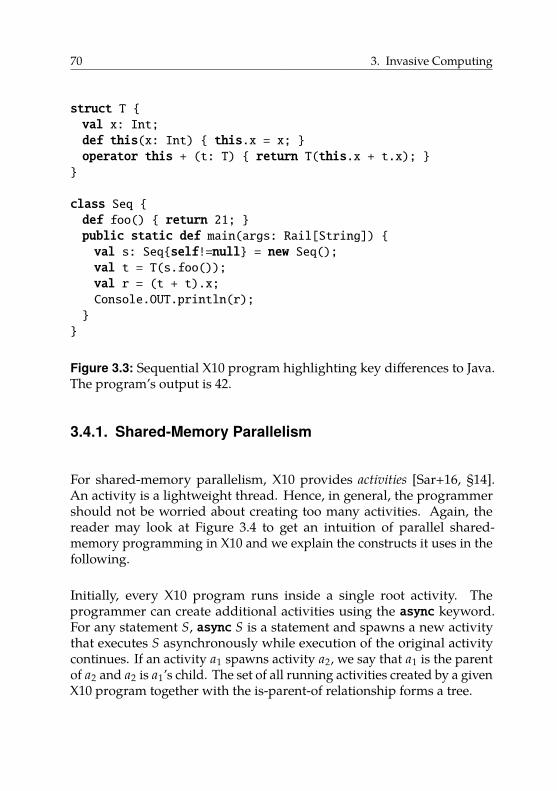
70 3. Invasive Computing
struct T {val x: Int;def this(x: Int) { this.x = x; }operator this + (t: T) { return T(this.x + t.x); }}
class Seq {def foo() { return 21; }public static def main(args: Rail[String]) {val s: Seq{self!=null} = new Seq();val t = T(s.foo());val r = (t + t).x;Console.OUT.println(r);}}
Figure 3.3: Sequential X10 program highlighting key differences to Java.The program’s output is 42.
3.4.1. Shared-Memory Parallelism
For shared-memory parallelism, X10 provides activities [Sar+16, §14].An activity is a lightweight thread. Hence, in general, the programmershould not be worried about creating too many activities. Again, thereader may look at Figure 3.4 to get an intuition of parallel shared-memory programming in X10 and we explain the constructs it uses in thefollowing.
Initially, every X10 program runs inside a single root activity. Theprogrammer can create additional activities using the async keyword.For any statement S, async S is a statement and spawns a new activitythat executes S asynchronously while execution of the original activitycontinues. If an activity a1 spawns activity a2, we say that a1 is the parentof a2 and a2 is a1’s child. The set of all running activities created by a givenX10 program together with the is-parent-of relationship forms a tree.
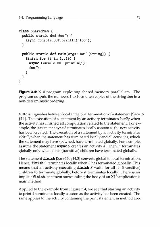
3.4. Programming Language 71
class SharedMem {public static def foo() {async Console.OUT.println("foo");}
public static def main(args: Rail[String]) {finish for (i in 1..10) {async Console.OUT.println(i);foo();}}}
Figure 3.4: X10 program exploiting shared-memory parallelism. Theprogram outputs the numbers 1 to 10 and ten copies of the string foo in anon-deterministic ordering.
X10 distinguishes between local and global termination of a statement [Sar+16,§14]. The execution of a statement by an activity terminates locally whenthe activity has finished all computation related to the statement. For ex-ample, the statement async S terminates locally as soon as the new activityhas been created. The execution of a statement by an activity terminatesglobally when the statement has terminated locally and all activities, whichthe statement may have spawned, have terminated globally. For example,assume the statement async S creates an activity a. Then, a terminatesglobally only when all its (transitive) children have terminated globally.
The statement finish [Sar+16, §14.3] converts global to local termination.Hence, finish S terminates locally when S has terminated globally. Thismeans that an activity executing finish S waits for all its (transitive)children to terminate globally, before it terminates locally. There is animplicit finish statement surrounding the body of an X10 application’smain method.
Applied to the example from Figure 3.4, we see that starting an activityto print i terminates locally as soon as the activity has been created. Thesame applies to the activity containing the print statement in method foo.
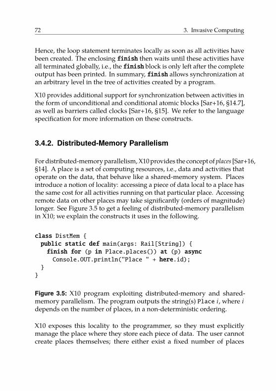
72 3. Invasive Computing
Hence, the loop statement terminates locally as soon as all activities havebeen created. The enclosing finish then waits until these activities haveall terminated globally, i.e., the finish block is only left after the completeoutput has been printed. In summary, finish allows synchronization atan arbitrary level in the tree of activities created by a program.
X10 provides additional support for synchronization between activities inthe form of unconditional and conditional atomic blocks [Sar+16, §14.7],as well as barriers called clocks [Sar+16, §15]. We refer to the languagespecification for more information on these constructs.
3.4.2. Distributed-Memory Parallelism
For distributed-memory parallelism, X10 provides the concept of places [Sar+16,§14]. A place is a set of computing resources, i.e., data and activities thatoperate on the data, that behave like a shared-memory system. Placesintroduce a notion of locality: accessing a piece of data local to a place hasthe same cost for all activities running on that particular place. Accessingremote data on other places may take significantly (orders of magnitude)longer. See Figure 3.5 to get a feeling of distributed-memory parallelismin X10; we explain the constructs it uses in the following.
class DistMem {public static def main(args: Rail[String]) {finish for (p in Place.places()) at (p) asyncConsole.OUT.println("Place " + here.id);
}}
Figure 3.5: X10 program exploiting distributed-memory and shared-memory parallelism. The program outputs the string(s) Place i, where idepends on the number of places, in a non-deterministic ordering.
X10 exposes this locality to the programmer, so they must explicitlymanage the place where they store each piece of data. The user cannotcreate places themselves; there either exist a fixed number of places
3.4. Programming Language 73
throughout the execution of a program, or the runtime environmentchanges the number of places [Bra+14; IBM14]. The programmer seesplaces as instances of type x10.lang.Place. Each place has a unique id;execution starts on the designated place Place.FIRST_PLACE. The specialvariable here always refers to the place that executes the current activity(similar to this).
X10 provides the place shifting operation at [Sar+16, §13.3] to performcomputations on other places. The at operation is a synchronous operationand does not spawn a new activity. Instead, the current activity changesits place of execution to the target place, continues executing there and,after it has terminated locally, control flow changes back to the originalplace.
The at operations exists in both statement and expression form. Hence,in addition to usage as in Figure 3.5, X10 also allows
val res = at (p) compute();
to call the method compute() on place p and receive the result in thelocal variable res. If evaluating an at statement or expression requiresadditional values (e.g., if compute required arguments), necessary valuesare copied to the respective place before the statement or expression isevaluated. We will discuss this in more detail in Section 4.4.
Synchronization using finish works across place boundaries. In theexample from Figure 3.5, the finish waits until the print operation on allplaces has finished.
To directly support the PGAS model, X10 provides the generic typeGlobalRef[T] as part of its standard library. GlobalRef[T] allows torefer to values of type T that are (potentially) located on other places. Theapplication operation (implemented as an overloaded operator()) allowsaccessing the value referenced by a GlobalRef.
public static def foo(g: GlobalRef[String]) {val s = at (g.home) g();// ... use string ...}
74 3. Invasive Computing
In this example, we see the definition of a method that takes as a parametera global reference g to a string object. We then retrieve the referencedstring value by using g(). Before we can access the value referencedby g, we must use at to shift to the place where the value lives. EachGlobalRef provides this place via the property home. The X10 type systemenforces that we only access values of GlobalRefs on their respectivehome places.
3.4.3. Related Work
In general, X10 is related to all programming languages following thePGAS model. We refer to [Alm11; De +15] for a comprehensive overviewand restrict our brief discussion to a few selected languages. We base ourpresentation on [Cha+05] and [De +15].
X10’s features for shared-memory parallelism are similar to Cilk [Blu+95].Where X10 has async and finish, Cilk has spawn and sync. However,X10’s constructs are more general due to the distinction between local andglobal termination described in Section 3.4.1. This distinction allows theparent activity to terminate while its children are still running.
Concerning distributed-memory parallelism, X10 falls in the group oflanguages designed as part of the High-Productivity Computing Systemsproject initiated by DARPA. Other languages developed as part of thisproject are Chapel [CCZ07] and Fortress [All+05]. All these languagesintegrate the PGAS model in the language itself instead of merely providingit via a library. Additionally, in contrast to earlier PGAS languages orlibraries, they use the so-called asynchronous PGAS model. They abandonthe traditional SPMD model, used, e.g., in MPI, in favor of a model whereprograms can spawn new threads dynamically and each thread can executedifferent code.
X10 shares some characteristics with Chapel. The concept of a place issimilar to locales in Chapel. However, in Chapel, objects can migratebetween locales, whereas in X10, an object is bound to a particular placethroughout its lifetime.
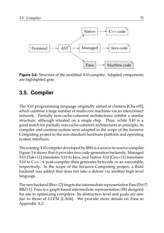
3.5. Compiler 75
Frontend AST Managed Java code
Native C++ code
Firm Machine code
Figure 3.6: Structure of the modified X10 compiler. Adapted componentsare highlighted gray.
3.5. Compiler
The X10 programming language originally aimed at clusters [Cha+05],which combine a large number of multi-core machines via an interconnectnetwork. Partially non-cache-coherent architectures exhibit a similarstructure, although situated on a single chip. Thus, while X10 is agood match for partially non-cache-coherent architectures in principle, itscompiler and runtime system were adapted in the scope of the InvasiveComputing project to the non-standard hardware platform and operatingsystem interfaces.
The existing X10 compiler developed by IBM is a source-to-source compiler.Figure 3.6 shows that it provides two code-generation backends: ManagedX10 [Tak+11] translates X10 to Java, and Native X10 [Gro+11] translatesX10 to C++. A post-compiler then generates bytecode or an executable,respectively. In the scope of the Invasive Computing project, a thirdbackend was added that does not take a detour via another high-levellanguage.
The new backend [Bra+12] targets the intermediate representation Firm [Fir17;BBZ11]. Firm is a graph-based intermediate representation (IR) designedfor use in optimizing compilers. Its abstraction level and goals are sim-ilar to those of LLVM [LA04]. We provide more details on Firm inAppendix A.2.
76 3. Invasive Computing
The existing compiler pipeline could be reused up to and including thesemantic-analysis phase. Using the new backend, the compiler thentranslates the resulting attributed abstract syntax tree (AST) into a Firmrepresentation.
While the translation is straightforward for most AST structures, someconstructs caused issues. The main cause of these issues was that bothexisting backends compile X10 to another high-level language of a similarlevel of abstraction. However, common compiler intermediate languagesmodel programs on a significantly lower level than C++ or Java. Hence,the existing compiler made some assumptions about the target languagethat did not hold for Firm.
In the following, we briefly discuss two required major modifications tothe X10 compiler concerning (i) the compilation of generic classes andmethods, and (ii) the handling of native methods. The modifications arenot specific to Firm but required for every target language of a similarabstraction level. We refer to [Bra+12] for details.
3.5.1. Compilation of Generic Classes and Methods
One important feature of modern programming languages is support forgeneric programming. For this purpose, Java and C++ offer generics andtemplates, respectively. Therefore, the existing X10 compiler backendscan map X10 generics to Java’s and C++’s available language mechanisms.The Java or C++ post-compiler then takes care of compiling the genericcode.
However, on the abstraction level of intermediate representations likeFirm, no support for genericity exists. Hence, in contrast to the existingbackends, for our new backend, we have to handle generic classes andmethods within the X10 compiler itself instead of leaving the handling tothe post-compiler. In the following, we will briefly explain our strategyfor handling generic methods and classes (referred to as “generic entities”in the following).
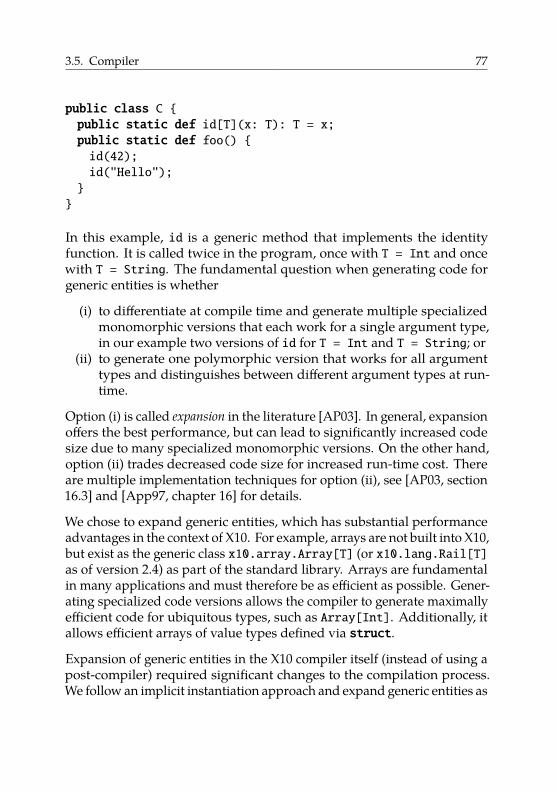
3.5. Compiler 77
public class C {public static def id[T](x: T): T = x;public static def foo() {id(42);id("Hello");}}
In this example, id is a generic method that implements the identityfunction. It is called twice in the program, once with T = Int and oncewith T = String. The fundamental question when generating code forgeneric entities is whether
(i) to differentiate at compile time and generate multiple specializedmonomorphic versions that each work for a single argument type,in our example two versions of id for T = Int and T = String; or
(ii) to generate one polymorphic version that works for all argumenttypes and distinguishes between different argument types at run-time.
Option (i) is called expansion in the literature [AP03]. In general, expansionoffers the best performance, but can lead to significantly increased codesize due to many specialized monomorphic versions. On the other hand,option (ii) trades decreased code size for increased run-time cost. Thereare multiple implementation techniques for option (ii), see [AP03, section16.3] and [App97, chapter 16] for details.
We chose to expand generic entities, which has substantial performanceadvantages in the context of X10. For example, arrays are not built into X10,but exist as the generic class x10.array.Array[T] (or x10.lang.Rail[T]as of version 2.4) as part of the standard library. Arrays are fundamentalin many applications and must therefore be as efficient as possible. Gener-ating specialized code versions allows the compiler to generate maximallyefficient code for ubiquitous types, such as Array[Int]. Additionally, itallows efficient arrays of value types defined via struct.
Expansion of generic entities in the X10 compiler itself (instead of using apost-compiler) required significant changes to the compilation process.We follow an implicit instantiation approach and expand generic entities as
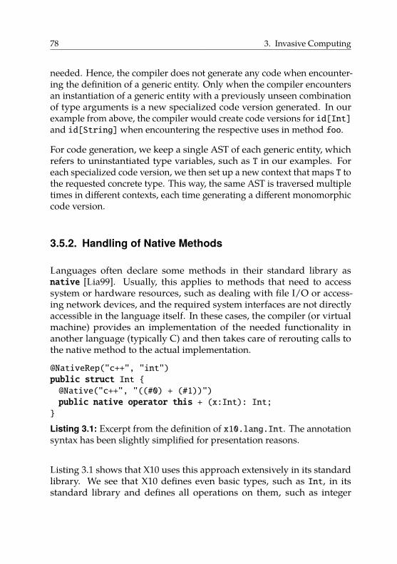
78 3. Invasive Computing
needed. Hence, the compiler does not generate any code when encounter-ing the definition of a generic entity. Only when the compiler encountersan instantiation of a generic entity with a previously unseen combinationof type arguments is a new specialized code version generated. In ourexample from above, the compiler would create code versions for id[Int]and id[String] when encountering the respective uses in method foo.
For code generation, we keep a single AST of each generic entity, whichrefers to uninstantiated type variables, such as T in our examples. Foreach specialized code version, we then set up a new context that maps T tothe requested concrete type. This way, the same AST is traversed multipletimes in different contexts, each time generating a different monomorphiccode version.
3.5.2. Handling of Native Methods
Languages often declare some methods in their standard library asnative [Lia99]. Usually, this applies to methods that need to accesssystem or hardware resources, such as dealing with file I/O or access-ing network devices, and the required system interfaces are not directlyaccessible in the language itself. In these cases, the compiler (or virtualmachine) provides an implementation of the needed functionality inanother language (typically C) and then takes care of rerouting calls tothe native method to the actual implementation.
@NativeRep("c++", "int")public struct Int {@Native("c++", "((#0) + (#1))")public native operator this + (x:Int): Int;}
Listing 3.1: Excerpt from the definition of x10.lang.Int. The annotationsyntax has been slightly simplified for presentation reasons.
Listing 3.1 shows that X10 uses this approach extensively in its standardlibrary. We see that X10 defines even basic types, such as Int, in itsstandard library and defines all operations on them, such as integer
3.5. Compiler 79
addition, as native methods. In this case, X10 overloads the operator + toprovide the familiar addition syntax.
This strategy has the advantage that there are fewer special cases inthe compiler itself, e.g., all operations on data types are represented asmethod calls in the AST. However, even if we represent basic arithmeticoperations, such as addition, as methods, we do not want to actually call amethod to add two integers. The existing backends use annotations asshown in Listing 3.1 to directly map fundamental types and their methodsto existing primitive types and operations in the target language. Theannotation syntax has been slightly simplified for presentation reasons.
We could have applied the same strategy to our new backend by addingFirm-specific annotations. However, as Firm operates on a significantlylower level than C++ and Java, some operations would be very cumbersometo express and the resulting annotations difficult to maintain.
Instead, we implemented a form of link-time optimization, enablingcross-language optimization. As shown in Figure 3.7, we implementall native parts of X10’s standard library as C functions, translate theseimplementations to Firm using the existing C frontend, and then combinethe resulting Firm IR with the Firm representation of the X10 program.We create the Firm representation of the standard library only once duringbuild time of the compiler and then load it when compiling an X10program.
To briefly illustrate how this process works, take the type Int fromListing 3.1 as an example. We provide a C implementation of a functionreturning the sum of its two integer arguments. After combining the FirmIR of this function with the Firm representation of the X10 program, wehave both the uses and the definition of the addition function available inthe same format (i.e., Firm graphs). Hence, regular function inlining caninline the body of the addition function (originating from C code) at the callsites (originating from X10 code) leading to efficient code, in this case thedesired single machine instruction for an integer addition. This approachoffers the high flexibility and compactness of providing implementationsin a high-level language like C while making it unnecessary to introducespecial cases or annotations.
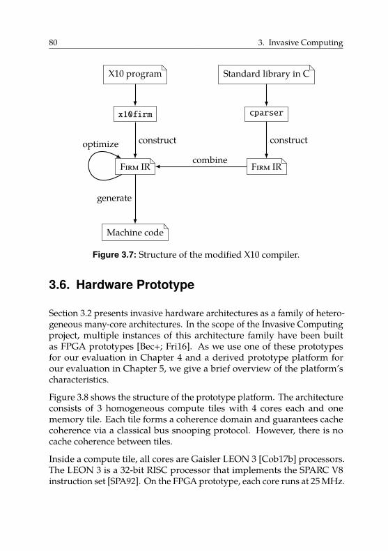
80 3. Invasive Computing
X10 program
x10firm
Firm IR
Machine code
constructoptimize
generate
Standard library in C
cparser
Firm IR
construct
combine
Figure 3.7: Structure of the modified X10 compiler.
3.6. Hardware Prototype
Section 3.2 presents invasive hardware architectures as a family of hetero-geneous many-core architectures. In the scope of the Invasive Computingproject, multiple instances of this architecture family have been builtas FPGA prototypes [Bec+; Fri16]. As we use one of these prototypesfor our evaluation in Chapter 4 and a derived prototype platform forour evaluation in Chapter 5, we give a brief overview of the platform’scharacteristics.
Figure 3.8 shows the structure of the prototype platform. The architectureconsists of 3 homogeneous compute tiles with 4 cores each and onememory tile. Each tile forms a coherence domain and guarantees cachecoherence via a classical bus snooping protocol. However, there is nocache coherence between tiles.
Inside a compute tile, all cores are Gaisler LEON 3 [Cob17b] processors.The LEON 3 is a 32-bit RISC processor that implements the SPARC V8instruction set [SPA92]. On the FPGA prototype, each core runs at 25 MHz.
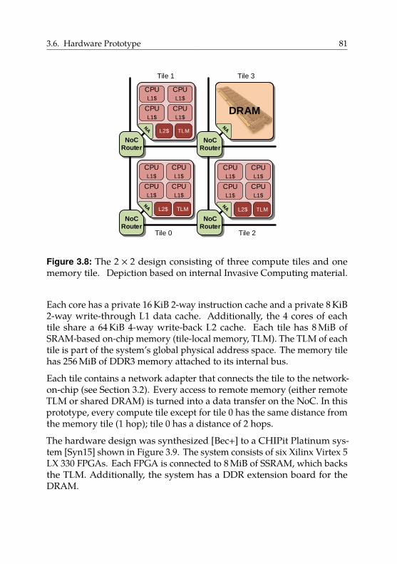
3.6. Hardware Prototype 81
CPU
L1$
CPU
L1$
CPU
L1$
CPU
L1$
L2$
CPU
L1$
CPU
L1$
CPU
L1$
CPU
L1$
DRAM
CPU
L1$
CPU
L1$
CPU
L1$
CPU
L1$
NoC
Router
NoC
Router
NoCRouter
NoC
Router
TLM
L2$ TLM L2$ TLM
Tile 0
Tile 1
Tile 2
Tile 3
Figure 3.8: The 2 × 2 design consisting of three compute tiles and onememory tile. Depiction based on internal Invasive Computing material.
Each core has a private 16 KiB 2-way instruction cache and a private 8 KiB2-way write-through L1 data cache. Additionally, the 4 cores of eachtile share a 64 KiB 4-way write-back L2 cache. Each tile has 8 MiB ofSRAM-based on-chip memory (tile-local memory, TLM). The TLM of eachtile is part of the system’s global physical address space. The memory tilehas 256 MiB of DDR3 memory attached to its internal bus.
Each tile contains a network adapter that connects the tile to the network-on-chip (see Section 3.2). Every access to remote memory (either remoteTLM or shared DRAM) is turned into a data transfer on the NoC. In thisprototype, every compute tile except for tile 0 has the same distance fromthe memory tile (1 hop); tile 0 has a distance of 2 hops.
The hardware design was synthesized [Bec+] to a CHIPit Platinum sys-tem [Syn15] shown in Figure 3.9. The system consists of six Xilinx Virtex 5LX 330 FPGAs. Each FPGA is connected to 8 MiB of SSRAM, which backsthe TLM. Additionally, the system has a DDR extension board for theDRAM.
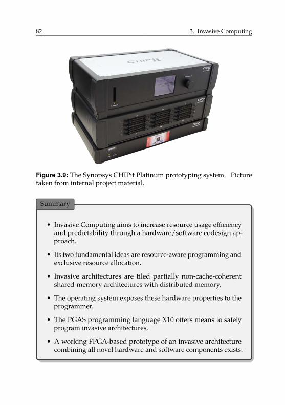
82 3. Invasive Computing
Figure 3.9: The Synopsys CHIPit Platinum prototyping system. Picturetaken from internal project material.
Summary
• Invasive Computing aims to increase resource usage efficiencyand predictability through a hardware/software codesign ap-proach.
• Its two fundamental ideas are resource-aware programming andexclusive resource allocation.
• Invasive architectures are tiled partially non-cache-coherentshared-memory architectures with distributed memory.
• The operating system exposes these hardware properties to theprogrammer.
• The PGAS programming language X10 offers means to safelyprogram invasive architectures.
• A working FPGA-based prototype of an invasive architecturecombining all novel hardware and software components exists.
Hello Woddd
Output of the first distributed X10 programrunning on an early hardware prototype 4
Compiling X10 to Invasive Architectures
In this chapter, we investigate the compilation of X10 (cf. Section 3.4)to invasive hardware architectures (cf. Section 3.2). First, we focus onintra-tile parallelism and describe the mapping of X10’s shared-memoryparallelism features to hardware inside a tile. Then, we turn towardsinter-tile parallelism. Here, we focus on data transfers between tiles. Morespecifically, we exhaustively study techniques for efficiently transferringflat as well as pointered data structures. We implement and thoroughlyevaluate these techniques on a prototype of an invasive architecture. Partsof this chapter have been published in [MT17], [Moh+15], and [Bra+14].
Motivation. We saw in Section 2.4 that different programming modelshave been proposed for and used on non-cache-coherent architectures.The shared-memory programming model is the most familiar model toprogrammers, but requires either fine-grained software-based coherencemanagement by the compiler or coarse-grained coherence managementby the operating system.
Alternatively, we can partition the address space on a logical level andmake each coherence domain the owner of one partition. This preventsaccesses to the same memory location from different coherence domains,
83
84 4. Compiling X10 to Invasive Architectures
as each coherence domain only reads and writes addresses from its ownmemory partition, thereby sidestepping the issues caused by missinghardware-based cache coherence. To communicate between domains wethen use explicit messages, which may make programming the systemmore difficult.
The PGAS model offers a compromise between both models where theprogrammer keeps some of the flexibility of the shared-memory program-ming model, namely the ability to point to arbitrary objects, while stillhaving the obligation to explicitly handle data placement.
However, just like the message-passing model, this model requires fre-quent data transfers between memory partitions. If one coherence domainR requires access to data located in the partition of another domainS, we must, in general, copy this data to R’s memory partition. Asthese operations can occur frequently, it is important to implement themefficiently.
We presented the general idea of how to implement data transfers on non-cache-coherent architectures in Section 2.4.3. However, general-purposeprograms, especially if written in modern object-oriented languages, poseadditional challenges. Here, programs often use pointered data structures,e.g., linked lists or trees. The standard approach to copy such a datastructure is to serialize it to a byte stream. We can then easily transferthis representation to another memory partition to deserialize a copy ofthe original data structure. However, this serialization can cause a largeoverhead, especially concerning memory usage.
Contribution. In this chapter, we investigate the compilation of thePGAS language X10 to invasive hardware architectures. Concerningintra-tile parallelism, we show how we efficiently handle the creationof a large number of activities without needing a user-level scheduler.Concerning inter-tile parallelism, we elaborately discuss possibilities toimplement data transfers between off-chip memory partitions. First,we focus on simple flat data structures and exhaustively discuss thestate of the art in the context of invasive architectures. Then, we turntowards complex pointered data structures. Here, our main contributionis a novel data-transfer technique to accelerate the transfer of pointered
85
data structures. Our technique is based on object cloning, which weextend with automatic compiler-controlled software-based coherencemanagement to make it usable on non-cache-coherent architectures, suchas invasive architectures. We implement a selection of the discusseddata-transfer techniques in the X10 compiler and extensively evaluatethe techniques on an FPGA-based prototype of an invasive architecture.Moreover, we identify opportunities for hardware support of coarse-grained software-based coherence management. We propose a matchinghardware extension and evaluate the area overhead of an FPGA-basedprototype implementation.
Structure. The structure of the following chapter is as follows:
• In Section 4.1, we explain how we efficiently implement X10’s featuresrelated to intra-tile parallelism on invasive architectures.
• In Section 4.2, we discuss inter-tile parallelism and identify datatransfers between off-chip memory partitions as an important build-ing block.
• In Section 4.3, we first describe the state of the art for transfersof simple contiguous data structures and then provide a detailedoverview of implementations on invasive hardware architectures.
• In Section 4.4, we then turn towards more complex pointered datastructures, where we also present our novel technique based onobject cloning.
• In Section 4.5, we show that cache operations on address rangescomplement the previously proposed data-transfer techniques. Wepresent an instruction-set extension and hardware implementationof non-blocking range-based cache operations.
• In Section 4.6, we evaluate the performance of data-transfer tech-niques for both flat and pointered data structures on an FPGA-basedprototype of an invasive architecture using both synthetic bench-marks as well as an existing testsuite of X10 programs. We alsoevaluate the overhead of our hardware extension.
86 4. Compiling X10 to Invasive Architectures
Acknowledgments. This chapter is based on publications that are jointwork with Matthias Braun, Sebastian Buchwald, Christoph Erhardt, DanielLohmann, Benjamin Oechslein, Jens Schedel, Carsten Tradowsky, andAndreas Zwinkau [Bra+14; Moh+15; MT17]. We include a description ofhow we map X10’s shared-memory features to hardware inside a tile inSection 4.1. This is not a central contribution of this dissertation and jointwork with Matthias Braun, Sebastian Buchwald, and Andreas Zwinkau.We still include this material for the sake of completeness.
The complete implementation of the range-based cache operations wedescribe in Section 4.5 was done by Michael Mechler and Carsten Trad-owsky [Mec16; MT17]. Additionally, the FPGA-based platform we use inSection 4.6 is the result of many contributions in the scope of the InvasiveComputing project. In particular, we use the following components:
• the X10 compiler (cf. Section 3.5), developed by Matthias Braun,Sebastian Buchwald, Eduard Frank, Andreas Fried, Tobias Kahlert,Tobias Rapp, Martin Seidel, Andreas Zwinkau, and the author;
• the operating system OctoPOS [Oec+11] (cf. Section 3.3), developedby Gabor Drescher, Christoph Erhardt, Daniel Lohmann, SebastianMaier, Benjamin Oechslein, Jens Schedel, and Florian Schmaus;
• the network-on-chip [Hei+14] including the network adapter [Zai+15],developed by Stephanie Friederich, Jan Heißwolf, Sven Rheindt, andAurang Zaib;
• the CiC [Rav15], developed by Ravi Kumar Pujari; and
• the FPGA-based prototype implementation [FHB14], developed bySrinivas Boppu, Stephanie Friederich, and David May, and SvenRheindt.
4.1. Intra-Tile Parallelism
X10 maps naturally to non-cache-coherent architectures, particularly topartially non-cache-coherent ones like invasive hardware architectures (cf.Section 3.2). The fundamental idea is as follows. We follow Section 2.4.4and partition the physical address space. Each coherence domain, i.e.,
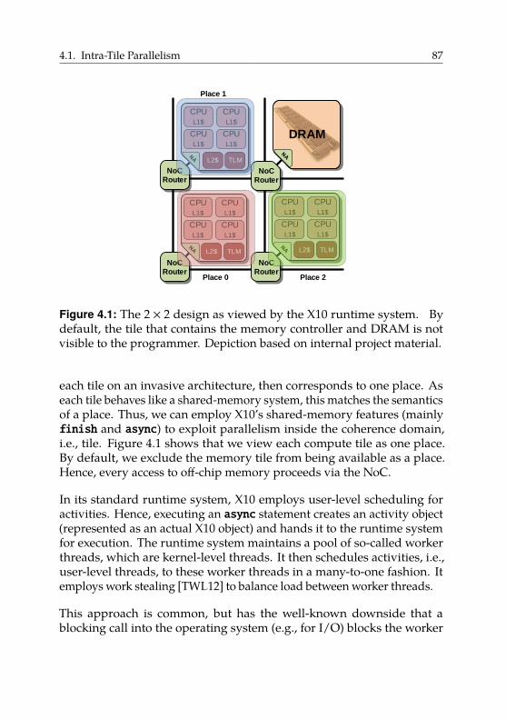
4.1. Intra-Tile Parallelism 87
CPU
L1$
CPU
L1$
CPU
L1$
CPU
L1$
L2$
CPU
L1$
CPU
L1$
CPU
L1$
CPU
L1$
DRAM
CPU
L1$
CPU
L1$
CPU
L1$
CPU
L1$
NoC
Router
NoC
Router
NoCRouter
NoC
Router
TLM
L2$ TLM L2$ TLM
Place 0
Place 1
Place 2
Figure 4.1: The 2 × 2 design as viewed by the X10 runtime system. Bydefault, the tile that contains the memory controller and DRAM is notvisible to the programmer. Depiction based on internal project material.
each tile on an invasive architecture, then corresponds to one place. Aseach tile behaves like a shared-memory system, this matches the semanticsof a place. Thus, we can employ X10’s shared-memory features (mainlyfinish and async) to exploit parallelism inside the coherence domain,i.e., tile. Figure 4.1 shows that we view each compute tile as one place.By default, we exclude the memory tile from being available as a place.Hence, every access to off-chip memory proceeds via the NoC.
In its standard runtime system, X10 employs user-level scheduling foractivities. Hence, executing an async statement creates an activity object(represented as an actual X10 object) and hands it to the runtime systemfor execution. The runtime system maintains a pool of so-called workerthreads, which are kernel-level threads. It then schedules activities, i.e.,user-level threads, to these worker threads in a many-to-one fashion. Itemploys work stealing [TWL12] to balance load between worker threads.
This approach is common, but has the well-known downside that ablocking call into the operating system (e.g., for I/O) blocks the worker
88 4. Compiling X10 to Invasive Architectures
thread with all activities it manages. The default X10 runtime systemworks around this problem by starting additional worker threads beforepotentially blocking operations. This implicates some overhead for thecreation and termination of worker threads before and after potentiallyblocking operations to keep the number of non-blocked worker threadsclose to the available hardware parallelism. Additionally, if this parallelismadaption is forgotten for a potentially blocking call, a core might idlealthough runnable activities exist.
On invasive architectures, we can implement asyncmore efficiently. Asinvasive architectures offer special hardware and operating system supportfor fine-grained parallelism in the form of i-lets, we can map each activitydirectly to an i-let. Hence, no representation of an X10 activity exists onthe level of the runtime system; each activity is an i-let.
This greatly simplifies the runtime system, as we do not need a user-level scheduler at all. As i-lets are lightweight, have run-to-completionsemantics, and use cooperative scheduling, OctoPOS can efficiently createand dispatch large numbers of i-lets. Hence, it is no problem to createone kernel-level thread per activity. Kernel-level threads of traditionaloperating systems are too heavyweight for this. Viewed another way,OctoPOS puts a user-level-like scheduler (and its properties) into itskernel.
We implement finish using one signal primitive (cf. Section 3.3) perfinish block. Each i-let remembers its corresponding finish as i-let-localdata, which resides at a designated location in the i-let’s context.
Concerning memory management, X10 requires a garbage collector.Hence, we ported a conservative garbage collector [BW88] to OctoPOS.We run a separate instance of the garbage collector per tile (i.e., one perplace, which is the default in X10). The garbage collector follows thestop-the-world approach and uses a mark-and-sweep strategy. As it isconservative, the garbage collector does not require much functionalityfrom the operating system or assistance by the compiler. Its two mainrequirements are (i) an interface to stop all running i-lets (except thecurrent one) on all cores of the tile, and (ii) an interface to query the stackbounds of all existing (blocked and unblocked) i-lets on the tile.
4.2. Inter-Tile Parallelism 89
By default, we configure the garbage collector to place the heap in thetile’s partition of the DRAM. Hence, we allocate all X10 objects in the tile’sDRAM partition. The TLM is reserved for use by the runtime system9.During its mark phase, the garbage collector scans the registers of theactive core, all stacks, the TLM, and the used part of the heap for potentialroot pointers.
As mentioned in Section 3.4, X10 provides GlobalRef to enable one placeto point to an object residing on a different place. We have to ensurethat these objects are not deleted on their home place, even if the onlyreferences to them exist on other places. As we do not use a distributedgarbage collector, we employ the same workaround as the original X10runtime: we save the addresses of objects referenced by a GlobalRef in aspecial data structure on their home place. These objects thus never getdeallocated automatically by the garbage collector.
4.2. Inter-Tile Parallelism
As explained in Section 3.4.2, X10 exposes data locality in the form ofplaces. Initially, all data resides on place Place.FIRST_PLACE and must bedistributed to other places in the course of a program run. Additionally, adistributed computation usually requires frequent data exchange betweenplaces.
Hence, on an invasive architecture, efficient data transfers between tilesare important for the performance of X10 programs. More specifically,we usually want to transfer data in the off-chip memory partition of onetile to the off-chip memory partition of another tile. In the following, wediscuss possible implementation techniques for such data transfers. Wefirst focus on simple bytewise copying of data, as it can serve as a buildingblock for all other transfer types. Then, we investigate transferring morecomplex structured data, such as linked lists or trees.
As we have seen in Section 3.2, the family of invasive hardware architecturesis diverse. To simplify our following discussion, we restrict ourselves
9We provide the annotation @TLMAllocate to enable user-controlled allocations in the TLM.However, these objects are not garbage-collected and have to be deleted manually.
90 4. Compiling X10 to Invasive Architectures
to one (simplified) instance of an invasive architecture that captures allproperties relevant to data transfers. We base our further discussions onthis instance. Subsequently, we discuss concrete implementations of thepresented data transfer approaches for the prototype hardware describedin Section 3.6.
We make the following observations about invasive architectures, whichlead to the model shown in Figure 4.2. Note that the upper box in Figure 4.2depicts the actual off-chip memory and not a logical address space as inFigure 2.9. Off-chip memory and all TLMs are part of the global physicaladdress space.
The whole system consists of the chip itself and off-chip main memory.A memory controller connects the chip to the off-chip memory. Theremay be multiple off-chip memories attached to multiple controllers, e.g.,one controller at each border of the chip with separate memory modules.Off-chip memory is DRAM-based and large (in the order of gigabytes). Weonly model one off-chip memory, as the existence of multiple memoriesor controllers is irrelevant in our context.
The cores are grouped into tiles. Cores have private caches and allcaches inside a tile are kept coherent by the hardware. A tile usuallycontains more than one core, constituting a partially non-cache-coherentarchitecture. In this case, multiple cores may share additional cache levels.The cores of a tile can also be heterogeneous. We restrict ourselves to onecore with one private cache in write-back configuration per tile. This isthe simplest setting that is at the same time complex enough to requiresoftware-managed coherence due to lack of hardware-based coherenceacross tile boundaries. However, the presented techniques also work withmore complex cache hierarchies.
Additionally, there is on-chip memory available to each tile in the form oftile-local memory (TLM). TLM is SRAM-based and small (in the order ofkilobytes to a few megabytes). In general, TLM offers higher bandwidthand lower latency compared to off-chip memory.
There is a global physical address space that includes off-chip memoryas well as all TLMs. Hence, we can use TLMs for direct tile-to-tilecommunication. We assume that caches cache the complete address space,i.e., accesses to both off-chip memory and all TLMs. Hence, in general, we
4.3. Block-Based Data Transfers 91
need to manage coherence in software for parts of the address space thatwe access from multiple tiles.
Tiles are connected to each other and to the memory controllers by ascalable network-on-chip. Accesses to off-chip memory and to remoteTLMs use this interconnect. We restrict ourselves to two tiles and thusstudy data transfers from one sending tile to one receiving tile, i.e., nobroadcasts or gather-like operations. Point-to-point communication isa fundamental operation on top of which we can implement all othercommunication patterns. We further assume that the off-chip memoryhas two logical partitions, one for each tile.
Throughout the following discussion, we assume a cache that offers twooperations: invalidate and writeback (cf. Section 2.2.2.3). Furthermore, weassume that all operations can be executed on the respective cache line fora given address. Invalidate marks a cache line as invalid, meaning that thenext time an address from the cached range is accessed, it will be fetchedfrom memory. Writeback writes a dirty cache line back to memory. Thecache line stays valid after this operation. We use flush as a shorthand fora write-back followed by an invalidation.
4.3. Block-Based Data Transfers
In this section, we study the bytewise copying of contiguous memoryblocks between shared-memory partitions on invasive architectures. Thisoperation is available to the X10 programmer in the form of the methodsArray.asyncCopy() and Rail.asyncCopy()10, which perform bytewisecopying of (parts of) an array between places11. In the following, we referto this operation as a shallow copy.
Hence, we want to copy a contiguous memory block B from the off-chipmemory partition of the sending tile S to a copy B′ of that memory blockin the off-chip memory partition of the receiving tile R; see Figure 4.3 for
10In X10 terminology, a Rail is a one-dimensional zero-indexed dense array.11Hence, these methods should only be used on arrays of value types, not on arrays of
references. Unfortunately, the X10 type system is not powerful enough to express thisrestriction, so the programmer must be careful.
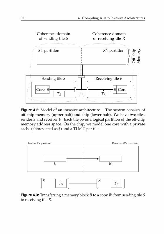
92 4. Compiling X10 to Invasive Architectures
S’s partition R’s partition
Sending tile S
Core $TS
Receiving tile R
Core$TR
Off-
chip
Mem
ory
Coherence domainof sending tile S
Coherence domainof receiving tile R
Figure 4.2: Model of an invasive architecture. The system consists ofoff-chip memory (upper half) and chip (lower half). We have two tiles:sender S and receiver R. Each tile owns a logical partition of the off-chipmemory address space. On the chip, we model one core with a privatecache (abbreviated as $) and a TLM T per tile.
TS TR
Sender S’s partition Receiver R’s partition
S R
B B′
Figure 4.3: Transferring a memory block B to a copy B′ from sending tile Sto receiving tile R.
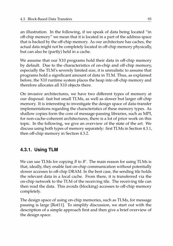
4.3. Block-Based Data Transfers 93
an illustration. In the following, if we speak of data being located “inoff-chip memory” we mean that it is located in a part of the address spacethat is backed by the off-chip memory. As our architecture has caches, theactual data might not be completely located in off-chip memory physically,but can also be (partly) held in a cache.
We assume that our X10 programs hold their data in off-chip memoryby default. Due to the characteristics of on-chip and off-chip memory,especially the TLM’s severely limited size, it is unrealistic to assume thatprograms hold a significant amount of data in TLM. Thus, as explainedbefore, the X10 runtime system places the heap into off-chip memory andtherefore allocates all X10 objects there.
On invasive architectures, we have two different types of memory atour disposal: fast but small TLMs, as well as slower but larger off-chipmemory. It is interesting to investigate the design space of data-transferimplementations regarding the characteristics of these memory types. Asshallow copies form the core of message-passing libraries, such as MPI,for non-cache-coherent architectures, there is a lot of prior work on thistopic. In the following, we give an overview of the state of the art. Wediscuss using both types of memory separately: first TLMs in Section 4.3.1,then off-chip memory in Section 4.3.2.
4.3.1. Using TLM
We can use TLMs for copying B to B′. The main reason for using TLMs isthat, ideally, they enable fast on-chip communication without potentiallyslower accesses to off-chip DRAM. In the best case, the sending tile holdsthe relevant data in a local cache. From there, it is transferred via theon-chip network to the TLM of the receiving tile. The receiving tile canthen read the data. This avoids (blocking) accesses to off-chip memorycompletely.
The design space of using on-chip memories, such as TLMs, for messagepassing is large [Rot11]. To simplify discussion, we start out with thedescription of a simple approach first and then give a brief overview ofthe design space.
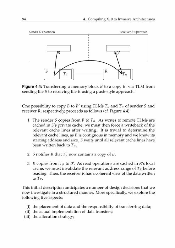
94 4. Compiling X10 to Invasive Architectures
TS TR
Sender S’s partition Receiver R’s partition
S R
B B′
Figure 4.4: Transferring a memory block B to a copy B′ via TLM fromsending tile S to receiving tile R using a push-style approach.
One possibility to copy B to B′ using TLMs TS and TR of sender S andreceiver R, respectively, proceeds as follows (cf. Figure 4.4):
1. The sender S copies from B to TR. As writes to remote TLMs arecached in S’s private cache, we must then force a writeback of therelevant cache lines after writing. It is trivial to determine therelevant cache lines, as B is contiguous in memory and we know itsstarting address and size. S waits until all relevant cache lines havebeen written back to TR.
2. S notifies R that TR now contains a copy of B.
3. R copies from TR to B′. As read operations are cached in R’s localcache, we must invalidate the relevant address range of TR beforereading. Then, the receiver R has a coherent view of the data writtento TR.
This initial description anticipates a number of design decisions that wenow investigate in a structured manner. More specifically, we explore thefollowing five aspects:
(i) the placement of data and the responsibility of transferring data;(ii) the actual implementation of data transfers;
(iii) the allocation strategy;
4.3. Block-Based Data Transfers 95
(iv) the synchronization mechanism to wait until write-back operationshave finished; and
(v) the notification mechanism to inform a remote tile of incoming data.
In the following, we briefly discuss each of these aspects. We partially baseour presentation on [Rot11, section IV] and refer to the same source for adetailed discussion of the message-passing design space in the context ofthe Intel SCC.
Placement and responsibility. Does the sender push messages to thereceiver’s TLM or does the receiver pull the message from the sender’sTLM? In our initial description we assumed the former, however, we couldalso copy from B to TS and then let R copy from TS to B′. While thesituations seem symmetric, architectural peculiarities or communicationpatterns other than point-to-point communication can make one approachsuperior. For example, to broadcast information it may be more efficientto place the message in the sender’s TLM and let all receivers pull fromit.
Transfers. How do we copy contiguous memory blocks? In the simplestcase, we use a core of either the sending or the receiving tile and executeregular load/store instructions in a loop. As our invasive hardwareprovides DMA units, we can also implement the transfer operationwithout CPU interaction. Both approaches may involve software-managedcoherence.
Allocation. How do we allocate the TLM, i.e., how do sender and receiveragree on which area of the TLM to use for a particular communicationoperation? One possibility is dynamic allocation, i.e., if the sender wantsto put a message into the receiver’s TLM, the sender explicitly requestsa memory area of the needed size before sending the message. Thisdoes not waste any space, because we allocate exactly what is neededwhen it is needed. However, it requires an additional forth-and-backcommunication between sender and receiver, which may be expensiverelative to the transfer of the actual message content, e.g., for very smallmessages.
96 4. Compiling X10 to Invasive Architectures
Alternatively, we can use a static allocation scheme. For example, on asystem with n tiles, we could partition each TLM into n − 1 partitionsand, for each memory, exclusively assign one partition to each other tilein the system. Hence, with a push-style data placement, the sending tilecould store the message to this sender’s exclusive part of the receiver’sTLM. Thereby, we avoid all run-time allocation overhead, but significantlydecrease the amount of data that can be sent with a single message. Forexample, Ureña et al. [URK] report a maximum message size of 160 byteson the Intel SCC when using 48 cores with a static allocation scheme forthe 16 KiB on-chip memory per tile.
Synchronization. How do we wait until writing back cache lines hasfinished? Here, the hardware must provide appropriate support. If thehardware guarantees that write operations are processed in programorder, implementation is straightforward. This is the solution chosen bythe Intel SCC [Mat+10, section III; Rot11, section II.B]. Here, the softwareonly has to ensure writing complete cache lines. Then, the hardwareguarantees that pending write requests complete before the next writerequest starts. If the hardware only gives weaker guarantees, it mustprovide support for awaiting the destination’s response that the writeoperation has completed.
Notification. How do we inform our communication partner that datahas arrived? In the simplest case, we manage, in each TLM, an array ofn − 1 boolean flags; one for each other tile in the system (assuming n tiles).If tile i wants to signal tile j, it sets the i-th flag in tile j’s array. Withsoftware-managed coherence and appropriate synchronization means(see above), this allows us to realize the required notification scheme.However, the resulting notification mechanism requires polling, which is,in general, inefficient. As such notification between tiles is a potentiallyfrequent operation, invasive hardware provides specialized support viathe remote spawning of i-lets described in Section 3.3.
As mentioned before, using TLMs provides a number of advantages: theyare decentralized and they provide higher bandwidth as well as lowerlatency compared to off-chip memory. Hence, we see that TLM allows usto implement efficient message-passing functionality.
4.3. Block-Based Data Transfers 97
However, they also require copying data between address space backed byoff-chip memory and TLMs. This becomes important if we consider largermessages. At some point, the message size exceeds the size of TLM12.Then, the sender must split the message into chunks and the receivermust reassemble these chunks. In the simplest case, the sender writesa chunk, waits until the receiver has acknowledged copying the chunkto its partition of the off-chip memory, and then writes the next chunk.This process is repeated until the complete message has been transmitted.Splitting and reassembling messages causes significant overhead.
To partially hide this overhead, we can use pipelined communication [Cla+11,section 3.2]. Here, we use multiple disjoint areas of the TLM. The senderwrites a first chunk and notifies the receiver. Then, the receiver copiesthe first message chunk from its local TLM to off-chip memory while, atthe same time, the sender writes the next chunk to a different area of thereceiver’s TLM.
However, regardless of how we design our message-passing scheme, wecannot avoid the problem that at some message size, the overhead forsplitting and reassembling messages is higher than the bandwidth andlatency advantages gained by using TLMs. At this point, it becomesworthwhile to exploit off-chip memory to transfer messages.
4.3.2. Using Off-Chip Memory
We can use off-chip memory to copy B to B′ as follows (see Figure 4.5):
1. copy & writeback: S copies B to B′ and then performs an explicitwriteback of the address range of B′. Then, S waits until all relevantcache lines have been written back to off-chip memory.
2. notify: S notifies R via a message that it is now safe to read from B′.
3. invalidate: R invalidates the address range B′ in its local cache toguarantee reading up-to-date values from memory. It can then workwith B′.
12Or the part of TLM that is used for the communication operation in case of a staticallocation scheme.
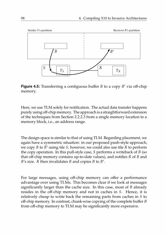
98 4. Compiling X10 to Invasive Architectures
TS TR
Sender S’s partition Receiver R’s partition
S R
B B′
Figure 4.5: Transferring a contiguous buffer B to a copy B′ via off-chipmemory.
Here, we use TLM solely for notification. The actual data transfer happenspurely using off-chip memory. The approach is a straightforward extensionof the techniques from Section 2.2.2.3 from a single memory location to amemory block, i.e., an address range.
The design space is similar to that of using TLM. Regarding placement, weagain have a symmetric situation: in our proposed push-style approach,we copy B to B′ using tile S, however, we could also use tile R to performthe copy operation. In this pull-style case, S performs a writeback of B (sothat off-chip memory contains up-to-date values), and notifies R of B andB’s size. R then invalidates B and copies B to B′.
For large messages, using off-chip memory can offer a performanceadvantage over using TLMs. This becomes clear if we look at messagessignificantly larger than the cache size. In this case, most of B alreadyresides in the off-chip memory and not in caches in S. Hence, it isrelatively cheap to write back the remaining parts from caches in S tooff-chip memory. In contrast, chunk-wise copying of the complete buffer Bfrom off-chip memory to TLM may be significantly more expensive.
4.3. Block-Based Data Transfers 99
4.3.3. Related Work
There has been a considerable amount of work on the efficient implemen-tation of message passing on non-cache-coherent architectures.
Rotta [Rot11] investigates efficient message-passing implementations usingon-chip memory on the Intel SCC. The author studies the design space ofmessage-passing protocols, identifies six design dimensions, and classifiesexisting approaches according to this framework.
Chapman et al. [CHH11] port X10 (cf. Section 3.4) to the Intel SCC. Theyonly use on-chip memory for message passing. They consider this abottleneck and report their plans to also use off-chip memory for messagepassing.
Ureña et al. [URK] present an MPI implementation for the Intel SCC.They observe that using off-chip memory is faster than on-chip mem-ory for passing messages of size 5.6 KiB and higher. Thus, their MPIimplementation chooses the communication channel (on-chip or off-chip)depending on the message size. In their experiments, off-chip memorywas marked uncacheable, i.e., accesses to off-chip memory were executedon a granularity of individual loads and stores (and not whole cachelines). This avoids the need for software-managed coherence, but sig-nificantly decreases performance [Cla+11]. In spite of this shortcoming,communicating via off-chip memory provided a performance advantagefor sufficiently large messages. With caching of off-chip memory enabled,the observed break-even point is likely to be at significantly lower messagesizes.
Clauss et al. [Cla+11] study the shared-memory and the message-passingprogramming models on the Intel SCC. They enable caching of the off-chip memory. Unfortunately, the Intel SCC provides no hardware meansfor fine-grained cache control. In particular, it does not allow forcingwritebacks or invalidations of the L2 cache (neither on individual lines noron the whole cache). Therefore, Clauss et al. use a workaround that readsfrom a sufficiently large contiguous memory area to evict the completecurrent L2-cache contents. Hence, this causes dirty lines to be writtenback to memory, i.e., flushes the complete L2 cache. However, while thisworkaround allowed Clauss et al. to confirm the functional correctness
100 4. Compiling X10 to Invasive Architectures
of their approach, the workaround’s significant overhead renders theirscalability measurements unrepresentative.
Van Tol et al. [Tol+11] investigate memory copy operations on the Intel SCC.They enable caching of the off-chip memory. Van Tol et al. propose “copycores”, which are dedicated cores that asynchronously copy memoryregions and are used by other cores as a service. Their implementationis also hindered by the missing means for invalidating and writing backL2-cache contents. In principle, this idea is also applicable to invasivearchitectures. However, the DMA unit present in every tile is preferable.
Reble et al. [RCL13] and Christgau et al. [CS16] present implementationsof MPI-based one-sided communication [Mes15, chapter 11] for theIntel SCC. With one-sided communication, one party is passive, i.e., theother party specifies all communication parameters. This contrasts two-sided communication, where each send operation requires a matchingreceive operation by a cooperating party. Reble et al. exploit both on-chipand off-chip memory for one-sided communication. However, they turnoff caching of off-chip memory and do not manage coherence in software.Despite the significant performance loss due to disabled caching, usingoff-chip memory is faster than using on-chip memory for sufficiently largemessages.
Christgau et al. improve upon this previous work by enabling caching ofoff-chip memory. However, they are also hindered by the missing L2-cachefunctionality. They work around this problem by using a special cachingpolicy available on the Intel SCC for shared off-chip memory (we discussthis topic in more detail in Section 4.5). Here, stores to these memoryareas are not cached. Read operations to this memory area are only cachedin the L1 cache, for which the Intel SCC offers a dedicated invalidationinstruction, but bypass the L2 cache. Despite being forced to use thisworkaround, they report a 5× reduction of communication costs for largemessages when compared to the default message-based implementation.As we have seen in Section 2.4.4, one-sided communication is importantfor PGAS languages. This supports our idea that precise cache control iscrucial on non-cache-coherent architectures, which we investigate in moredetail in Section 4.5.
We developed our approach to transfer data via off-chip memory inde-pendently of Christgau et al. Christgau et al.’s main contributions are
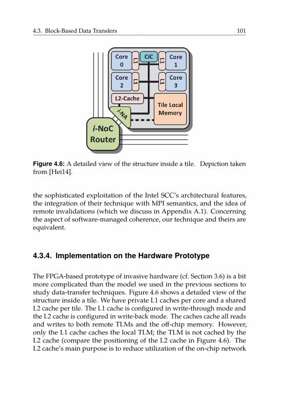
4.3. Block-Based Data Transfers 101
Figure 4.6: A detailed view of the structure inside a tile. Depiction takenfrom [Hei14].
the sophisticated exploitation of the Intel SCC’s architectural features,the integration of their technique with MPI semantics, and the idea ofremote invalidations (which we discuss in Appendix A.1). Concerningthe aspect of software-managed coherence, our technique and theirs areequivalent.
4.3.4. Implementation on the Hardware Prototype
The FPGA-based prototype of invasive hardware (cf. Section 3.6) is a bitmore complicated than the model we used in the previous sections tostudy data-transfer techniques. Figure 4.6 shows a detailed view of thestructure inside a tile. We have private L1 caches per core and a sharedL2 cache per tile. The L1 cache is configured in write-through mode andthe L2 cache is configured in write-back mode. The caches cache all readsand writes to both remote TLMs and the off-chip memory. However,only the L1 cache caches the local TLM; the TLM is not cached by theL2 cache (compare the positioning of the L2 cache in Figure 4.6). TheL2 cache’s main purpose is to reduce utilization of the on-chip network
102 4. Compiling X10 to Invasive Architectures
due to possibly frequent L1-cache misses when accessing remote data(remote TLM or off-chip).
In the following, we present possible implementations of the necessaryfunctionality we identified in Sections 4.3.1 and 4.3.2: (i) transfers, (ii) syn-chronization, and (iii) notification.
Transfers. To transfer data between TLMs of a sending tile S and areceiving tile R, we have three alternatives. First, we can use i-lets. Ani-let can carry two 32-bit words. Hence, for very small transfers, we candirectly encode data into an i-let, spawn it on R and let it write the datato the target location [Moh+15]. As we also use i-lets as our notificationmechanism (see below), it is almost always preferable to integrate a datatransfer if possible.
Second, we can write to the remote TLM using regular stores13. Thesestores are cached by the sender’s local L2 cache. Hence, we now have tomanage coherence in software to guarantee that written data is actuallyvisible to the receiver. We use platform-specific operations [Cob16, section74.3.3] to force writebacks of individual L2 cache lines. The providedinterface allows to supply an address whose corresponding cache line isthen looked up and written back. This allows to implement the writebackof an address range [S, E] with a cache line size of L using a loop asfollows:
for x := S − (S mod L) to E − (E mod L) step L:writeback(x)
We use mod to denote the modulus operation on integers. The termA − (A mod L) rounds the address A down to the nearest multiple of L14.Hence, the loop issues one writeback operation per relevant cache line.Writing back one cache line takes 6 clock cycles [Cob16, section 74.3.3]plus the latency for handing the cache line to the network-on-chip.
We do not have to manage coherence in software on the receiving side.On the receiving tile, its network adapter receives the stores issued by
13The “swcpy” variant of OctoPOS uses this mechanism.14If L is a power of two, we can express the term more efficiently using bitwise operations,
e.g., A & ~(L - 1) in C notation.
4.3. Block-Based Data Transfers 103
the sending tile and translates them to stores inside the receiving tile.Hence, these stores trigger the tile-local hardware coherence mechanismand invalidate potential copies of the written TLM parts in the L1 cachesof R’s cores.
The third and preferred method for transferring data between TLMs arepush-DMA transfers (cf. Section 3.3). The network adapter of each tileincludes a DMA unit capable of copying contiguous memory blocks fromthe tile’s local TLM to a remote memory without CPU interaction [Hei14,section 3.2.2.1]. Unfortunately, in the current hardware prototype, theremote memory can only be another TLM. Currently, the DMA unit cannotcopy from TLM to off-chip memory.
Figure 4.7 shows the full control flow of a DMA-based data transfer. Asthe first step, we copy from B to BS in the sender’s TLM. We use a dynamicallocation strategy for our TLMs. Hence, before we can initiate a DMAtransfer, we allocate the destination buffer in R’s TLM. We spawn a remotei-let on R, allocate the buffer BR in R’s TLM, and pass the address back toS via another remote i-let spawning.
After setting up our target buffer, S initiates a push-DMA transfer fromBS to BR. We specify two i-lets to execute once the data transfer hasfinished:
1. the first i-let runs on S and frees the source buffer BS; and2. the second i-let runs on R and copies BR to B′ in off-chip memory,
to free up the TLM space of BR subsequently.
In case S’s TLM cannot hold a copy of B, we have to split B into as manychunks as needed and transmit each chunk using one DMA transfer. Then,only the last DMA transfer triggers i-lets to free the source buffer on thesender and work with B′ on the receiver.
Copying data between TLMs using the hardware-based DMA transferdoes not require software-managed coherence. As the L2 cache does notcache accesses to the local TLM and the L1 cache is write-through, thesender’s network adapter can directly read up-to-date values from the localTLM. Then, the network-on-chip passes the data to the target tile’s networkadapter. On the target tile, the network adapter writes the transmittedmemory block to the target tile’s TLM. This write operation again triggersthe tile-local hardware coherence mechanism, which invalidates potential
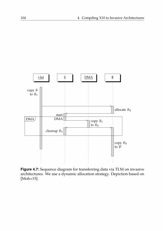
104 4. Compiling X10 to Invasive Architectures
i-let S DMA R
DMADMA
copy BRto B′
copy Bto BS
allocate BR
startDMA copy BS
to BR
cleanup BS
Figure 4.7: Sequence diagram for transferring data via TLM on invasivearchitectures. We use a dynamic allocation strategy. Depiction based on[Moh+15].
4.3. Block-Based Data Transfers 105
copies of the written TLM part in the receiver’s cores’ L1 caches. Thus,after the write has finished, all cores of the target tile have a coherent viewof the copied data in the target TLM.
To transfer data via off-chip memory, we need to manage coherence insoftware on both sending and receiving side. The reason for this is thatnow the memory is “remote” from the view of both parties. Hence, incontrast to the on-chip case, the writes that affect the target memory arenot visible to the receiver’s caches, as the involved network adapter islocated on the memory tile. Thus, no coherence actions are triggered, e.g.,no L1-cache invalidations happen on the sending or the receiving tile.
Therefore, after writing a memory block located in off-chip memory, wemust write back the respective address range. Before reading this memoryblock on the receiving side, we must invalidate its address range. Wemust do this on both levels of the cache hierarchy.
Hence, on the sending tile, we must write back the address range first inthe L1 caches and then in the L2 cache. As the L1 caches are configured inwrite-through mode, the write-back can be omitted. We write back therelevant L2 cache part using the method described above.
On the receiving tile, we need to invalidate the relevant parts of bothL1 cache and L2 cache. For the L2 cache, we use the same software-basedloop construct as for write-backs, but with an invalidate operation. Theprovided interface is the same as for writing back cache lines [Cob16,section 74.3.3]: we supply an address whose corresponding cache line isthen looked up and invalidated. Invalidating one cache line takes 5 clockcycles [Cob16, section 74.3.3].
Unfortunately, the L1 data cache offers no such fine-grained control: itcan only be flushed completely [Cob16, section 77.10.7] (we later improvethis situation in Section 4.5). However, as the cache is configured in write-through mode, no modified data is written back. Therefore, the resultingoverhead consists of a higher than necessary number of subsequentL1 cache misses, which are mostly compensated by the L2 cache.
Synchronization. In order to wait until writing back cache lines hasfinished, we use the following implementation. The L2 cache blocks all
106 4. Compiling X10 to Invasive Architectures
accesses (i.e., further loads or stores) until prior write-back operationshave finished [Cob16, section 74.3.3]. However, the invasive hardwareprototype, in contrast to the Intel SCC as described in Section 4.3.1, does notguarantee that pending write requests to remote memory complete beforethe next write request can start. Thus, as soon as the network adapter hashanded the cache line of a write-back operation to the network-on-chip,the next write-back operation can proceed. There is no acknowledgment,i.e., the hardware does not wait for this cache line to be actually writtenback to remote memory.
However, the invasive NoC guarantees that loads do not overtake pre-ceding stores to the same destination tile. Hence, after issuing all ourwrite-back operations, we load from a reserved address W in the remotememory. This load from W only completes once the previous write-backshave finished. It is crucial that we really load from remote memory andnot from a local cache. To prevent that the load from W is served by acache, we take the following precautions:
• For each core c in the system, we use a different address Wc . Alladdresses Wc are aligned so that they reside in different cache lines.Hence, there can be no interference between the synchronizationoperations of multiple cores.
• We invalidate the L2 cache line of Wc before reading.• To load from Wc , we use a cache-bypassing load instruction [Cob16,
section 77.10.2] that bypasses the L1 cache. On our platform, thisdoes not bypass the L2 cache, hence the explicit invalidation of theL2 cache line is required.
Notification. To implement notification, we have two alternatives. First,we can use the mechanism described in Section 4.3.1, i.e., stores to dedicatednotification flags located in TLMs in conjunction with software-managedcoherence. OctoPOS uses this scheme during early bootup before allhardware has been properly initialized.
However, as notification is a frequent operation, invasive architectures pro-vide dedicated hardware support. The preferred method for notificationbetween tiles works via i-lets. Hence, to notify the receiver of a message,we spawn an i-let on the receiving tile. There, the i-let can locally triggerthe appropriate action, e.g., using signaling primitives (cf. Section 3.3).
4.3. Block-Based Data Transfers 107
Before spawning the i-let, we have to ensure the completion of potentialwrite-back operations using synchronization as described above.
In the case of a DMA transfer, the hardware provides support for startingi-lets on the sending and the receiving sides as soon as the data has beentransferred completely (cf. Section 3.3). This allows us to merge synchro-nization, notification, and the actual data transfer into one operation thatis fully hardware-accelerated.
Implementation of asyncCopy(). In the following, we use the presentedbuilding blocks for transfers, synchronization, and notification to describetwo concrete implementations of X10’s Rail.asyncCopy()method: Ac-Tlm, which uses TLM, and Ac-Off, which uses off-chip memory to transferdata. The method Rail.asyncCopy() actually exists in two variants: oneto push data, i.e., to copy from a local array to a remote array, and one topull data, i.e., to copy from a remote array to a local array. We focus on thepush-style transfer; the pull-style variant works analogously. We assumea call like Rail.asyncCopy(B, B′).
We implement Ac-Tlm as follows. We use a dynamic allocation strategyfor the TLM. Then, we copy from B to BS in S’s TLM and use a push-DMA transfer to copy BS to BR. The receiver then copies BR to B′. Thehardware handles synchronization and notification; as described before,no software-managed coherence is necessary.
We implement Ac-Off as follows. We use a core of the sending tile tocopy B directly to B′. Then, we trigger a write-back of all L2 cache linesrelevant for B′. We synchronize and then spawn an i-let on the tile R thatinvalidates the complete L1 cache and the relevant L2 cache lines for B′.
Here, we have to be careful as multiple L1 caches exist on R. In general, toguarantee coherence, we must invalidate the address range of B′ in all ofthem. Either we ensure that the i-let that issues the invalidation is the onlyi-let that ever accesses B′ on R. Due to our restricted scheduling policy,i-lets never change their core unless they block, in which case they maybe scheduled on a different core in the same claim. Hence, on invasivearchitectures, we have some control over whether an i-let gets rescheduled.Or, if other cores may also access B′, we must issue invalidations on allcores of tile R. We discuss this topic again in Appendix A.1.
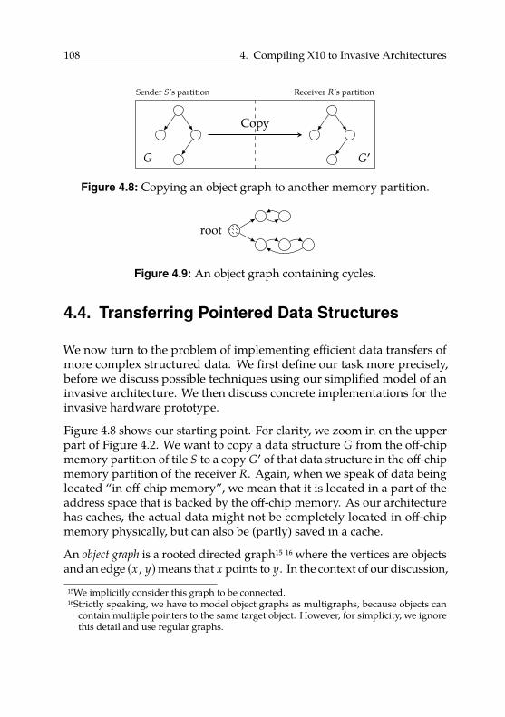
108 4. Compiling X10 to Invasive Architectures
Sender S’s partition Receiver R’s partition
G G′
Copy
Figure 4.8: Copying an object graph to another memory partition.
root
Figure 4.9: An object graph containing cycles.
4.4. Transferring Pointered Data Structures
We now turn to the problem of implementing efficient data transfers ofmore complex structured data. We first define our task more precisely,before we discuss possible techniques using our simplified model of aninvasive architecture. We then discuss concrete implementations for theinvasive hardware prototype.
Figure 4.8 shows our starting point. For clarity, we zoom in on the upperpart of Figure 4.2. We want to copy a data structure G from the off-chipmemory partition of tile S to a copy G′ of that data structure in the off-chipmemory partition of the receiver R. Again, when we speak of data beinglocated “in off-chip memory”, we mean that it is located in a part of theaddress space that is backed by the off-chip memory. As our architecturehas caches, the actual data might not be completely located in off-chipmemory physically, but can also be (partly) saved in a cache.
An object graph is a rooted directed graph15 16 where the vertices are objectsand an edge (x , y)means that x points to y. In the context of our discussion,
15We implicitly consider this graph to be connected.16Strictly speaking, we have to model object graphs as multigraphs, because objects can
contain multiple pointers to the same target object. However, for simplicity, we ignorethis detail and use regular graphs.
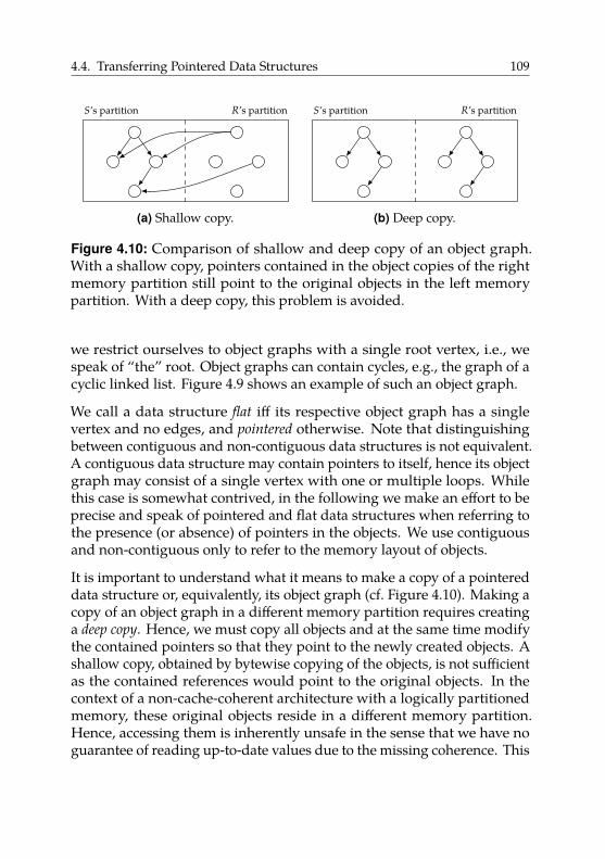
4.4. Transferring Pointered Data Structures 109
S’s partition R’s partition
(a) Shallow copy.
S’s partition R’s partition
(b) Deep copy.
Figure 4.10: Comparison of shallow and deep copy of an object graph.With a shallow copy, pointers contained in the object copies of the rightmemory partition still point to the original objects in the left memorypartition. With a deep copy, this problem is avoided.
we restrict ourselves to object graphs with a single root vertex, i.e., wespeak of “the” root. Object graphs can contain cycles, e.g., the graph of acyclic linked list. Figure 4.9 shows an example of such an object graph.
We call a data structure flat iff its respective object graph has a singlevertex and no edges, and pointered otherwise. Note that distinguishingbetween contiguous and non-contiguous data structures is not equivalent.A contiguous data structure may contain pointers to itself, hence its objectgraph may consist of a single vertex with one or multiple loops. Whilethis case is somewhat contrived, in the following we make an effort to beprecise and speak of pointered and flat data structures when referring tothe presence (or absence) of pointers in the objects. We use contiguousand non-contiguous only to refer to the memory layout of objects.
It is important to understand what it means to make a copy of a pointereddata structure or, equivalently, its object graph (cf. Figure 4.10). Making acopy of an object graph in a different memory partition requires creatinga deep copy. Hence, we must copy all objects and at the same time modifythe contained pointers so that they point to the newly created objects. Ashallow copy, obtained by bytewise copying of the objects, is not sufficientas the contained references would point to the original objects. In thecontext of a non-cache-coherent architecture with a logically partitionedmemory, these original objects reside in a different memory partition.Hence, accessing them is inherently unsafe in the sense that we have noguarantee of reading up-to-date values due to the missing coherence. This
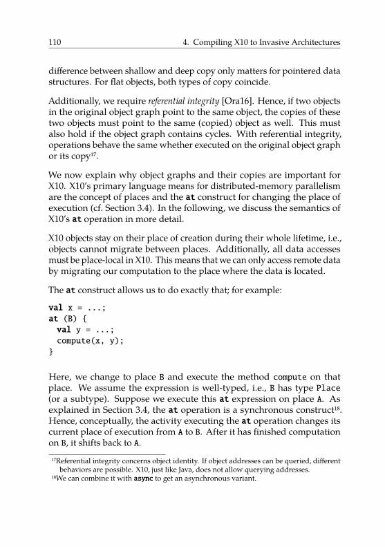
110 4. Compiling X10 to Invasive Architectures
difference between shallow and deep copy only matters for pointered datastructures. For flat objects, both types of copy coincide.
Additionally, we require referential integrity [Ora16]. Hence, if two objectsin the original object graph point to the same object, the copies of thesetwo objects must point to the same (copied) object as well. This mustalso hold if the object graph contains cycles. With referential integrity,operations behave the same whether executed on the original object graphor its copy17.
We now explain why object graphs and their copies are important forX10. X10’s primary language means for distributed-memory parallelismare the concept of places and the at construct for changing the place ofexecution (cf. Section 3.4). In the following, we discuss the semantics ofX10’s at operation in more detail.
X10 objects stay on their place of creation during their whole lifetime, i.e.,objects cannot migrate between places. Additionally, all data accessesmust be place-local in X10. This means that we can only access remote databy migrating our computation to the place where the data is located.
The at construct allows us to do exactly that; for example:
val x = ...;at (B) {val y = ...;compute(x, y);}
Here, we change to place B and execute the method compute on thatplace. We assume the expression is well-typed, i.e., B has type Place(or a subtype). Suppose we execute this at expression on place A. Asexplained in Section 3.4, the at operation is a synchronous construct18.Hence, conceptually, the activity executing the at operation changes itscurrent place of execution from A to B. After it has finished computationon B, it shifts back to A.
17Referential integrity concerns object identity. If object addresses can be queried, differentbehaviors are possible. X10, just like Java, does not allow querying addresses.
18We can combine it with async to get an asynchronous variant.

4.4. Transferring Pointered Data Structures 111
class Foo {var p: Foo;def this(q: Foo) { p = q; }static def bar() {val a = new Foo(null);val b = new Foo(a);a.p = b;val x = new Foo(a);at (B) {val y = new Foo(null);compute(x, y);}}}
(a) X10 code.
ox oa ob
(b) Object graph.
Figure 4.11: An X10 program containing an at expression that capturesvariables, and the matching object graph.
The body S of a statement at (B) S is allowed to refer to variables thatare not defined in S itself. In our example, the call to compute refers to x,which is defined in an enclosing scope. However, as all data access mustbe place-local, we cannot access x on B.
Therefore, X10 semantics dictate that the values of all free variables inSmust be copied from A to B before S is executed on B [Sar+16, §13.3.1].Hence, X10’s at statements close over the values of the free variables in S.To implement this semantics, the X10 compiler first determines the setof free variables F in S. Extending our initial example to the examplefrom Figure 4.11a, the X10 compiler determines the set of free variablesF � {x}.Then, at run-time, at the program point where the at expression is to beexecuted, all variables in F are evaluated, resulting in a set V of values.The X10 runtime system now determines the set V∗ of all values that aretransitively reachable from values in V . Using V∗ as the vertex set andthe (immediate) reachability relation as the edge set, this results in an
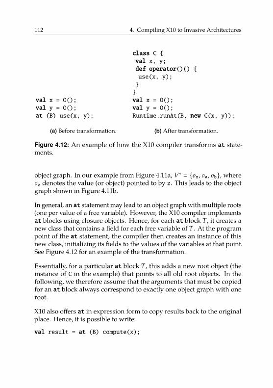
112 4. Compiling X10 to Invasive Architectures
val x = O();val y = O();at (B) use(x, y);
(a) Before transformation.
class C {val x, y;def operator()() {use(x, y);}}val x = O();val y = O();Runtime.runAt(B, new C(x, y));
(b) After transformation.
Figure 4.12: An example of how the X10 compiler transforms at state-ments.
object graph. In our example from Figure 4.11a, V∗ � {ox , oa , ob}, whereoz denotes the value (or object) pointed to by z. This leads to the objectgraph shown in Figure 4.11b.
In general, an at statement may lead to an object graph with multiple roots(one per value of a free variable). However, the X10 compiler implementsat blocks using closure objects. Hence, for each at block T, it creates anew class that contains a field for each free variable of T. At the programpoint of the at statement, the compiler then creates an instance of thisnew class, initializing its fields to the values of the variables at that point.See Figure 4.12 for an example of the transformation.
Essentially, for a particular at block T, this adds a new root object (theinstance of C in the example) that points to all old root objects. In thefollowing, we therefore assume that the arguments that must be copiedfor an at block always correspond to exactly one object graph with oneroot.
X10 also offers at in expression form to copy results back to the originalplace. Hence, it is possible to write:
val result = at (B) compute(x);
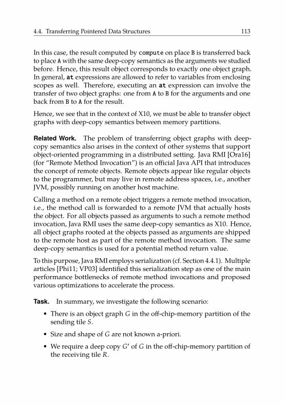
4.4. Transferring Pointered Data Structures 113
In this case, the result computed by compute on place B is transferred backto place Awith the same deep-copy semantics as the arguments we studiedbefore. Hence, this result object corresponds to exactly one object graph.In general, at expressions are allowed to refer to variables from enclosingscopes as well. Therefore, executing an at expression can involve thetransfer of two object graphs: one from A to B for the arguments and oneback from B to A for the result.
Hence, we see that in the context of X10, we must be able to transfer objectgraphs with deep-copy semantics between memory partitions.
Related Work. The problem of transferring object graphs with deep-copy semantics also arises in the context of other systems that supportobject-oriented programming in a distributed setting. Java RMI [Ora16](for “Remote Method Invocation”) is an official Java API that introducesthe concept of remote objects. Remote objects appear like regular objectsto the programmer, but may live in remote address spaces, i.e., anotherJVM, possibly running on another host machine.
Calling a method on a remote object triggers a remote method invocation,i.e., the method call is forwarded to a remote JVM that actually hoststhe object. For all objects passed as arguments to such a remote methodinvocation, Java RMI uses the same deep-copy semantics as X10. Hence,all object graphs rooted at the objects passed as arguments are shippedto the remote host as part of the remote method invocation. The samedeep-copy semantics is used for a potential method return value.
To this purpose, Java RMI employs serialization (cf. Section 4.4.1). Multiplearticles [Phi11; VP03] identified this serialization step as one of the mainperformance bottlenecks of remote method invocations and proposedvarious optimizations to accelerate the process.
Task. In summary, we investigate the following scenario:
• There is an object graph G in the off-chip-memory partition of thesending tile S.
• Size and shape of G are not known a-priori.
• We require a deep copy G′ of G in the off-chip-memory partition ofthe receiving tile R.
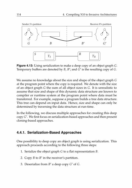
114 4. Compiling X10 to Invasive Architectures
TS TR
Sender S’s partition Receiver R’s partition
S R
G B B′ G′
Figure 4.13: Using serialization to make a deep copy of an object graph G.Temporary buffers are denoted by B, B′; and G′ is the resulting copy of G.
We assume no knowledge about the size and shape of the object graph Gat the program point where the copy is required. We denote with the sizeof an object graph G the sum of all object sizes in G. It is unrealistic toassume that size and shape of this dynamic data structure are known tocompiler or runtime system at the program point where data must betransferred. For example, suppose a program builds a tree data structure.This tree can depend on input data. Hence, size and shape can only bedetermined by traversing the data structure at run-time.
In the following, we discuss multiple approaches for creating this deepcopy G′. We first focus on serialization-based approaches and then presentcloning-based approaches.
4.4.1. Serialization-Based Approaches
One possibility to deep copy an object graph is using serialization. Thisapproach proceeds according to the following three steps:
1. Serialize the object graph G to a flat representation B.
2. Copy B to B′ in the receiver’s partition.
3. Deserialize from B′ a deep copy G′ of G.
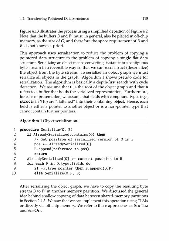
4.4. Transferring Pointered Data Structures 115
Figure 4.13 illustrates the process using a simplified depiction of Figure 4.2.Note that the buffers B and B′ must, in general, also be placed in off-chipmemory, as the size of G, and therefore the space requirement of B andB′, is not known a-priori.
This approach uses serialization to reduce the problem of copying apointered data structure to the problem of copying a single flat datastructure. Serializing an object means converting its state into a contiguousbyte stream in a reversible way so that we can reconstruct (deserialize)the object from the byte stream. To serialize an object graph we mustserialize all objects in the graph. Algorithm 1 shows pseudo code forserialization. The algorithm is basically a depth-first search with cycledetection. We assume that O is the root of the object graph and that Brefers to a buffer that holds the serialized representation. Furthermore,for ease of presentation, we assume that fields with compound types (e.g.,structs in X10) are “flattened” into their containing object. Hence, eachfield is either a pointer to another object or is a non-pointer type thatcannot contain further pointers.
Algorithm 1 Object serialization.
1 procedure Serialize(O, B)2 if AlreadySerialized.contains(O) then3 // Get position of serialized version of O in B4 pos ← AlreadySerialized[O]5 B.append(reference to pos)6 return7 AlreadySerialized[O] ← current position in B8 for each F in O.type.fields do9 if ¬F.type.pointer then B.append(O.F)
10 else Serialize(O.F, B)
After serializing the object graph, we have to copy the resulting bytestream B to B′ in another memory partition. We discussed the generalidea behind shallow copying of data between shared-memory partitionsin Section 2.4.3. We saw that we can implement this operation using TLMsor directly via off-chip memory. We refer to these approaches as Ser-Tlmand Ser-Off.
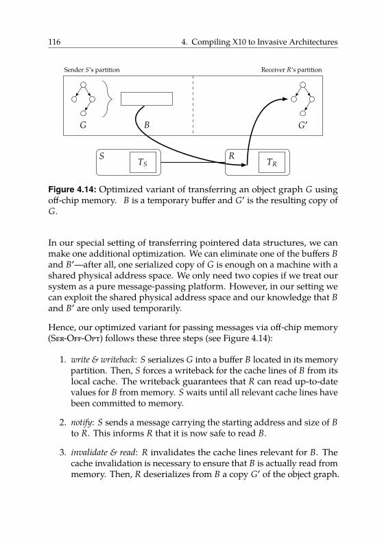
116 4. Compiling X10 to Invasive Architectures
TS TR
Sender S’s partition Receiver R’s partition
S R
G B G′
Figure 4.14: Optimized variant of transferring an object graph G usingoff-chip memory. B is a temporary buffer and G′ is the resulting copy ofG.
In our special setting of transferring pointered data structures, we canmake one additional optimization. We can eliminate one of the buffers Band B′—after all, one serialized copy of G is enough on a machine with ashared physical address space. We only need two copies if we treat oursystem as a pure message-passing platform. However, in our setting wecan exploit the shared physical address space and our knowledge that Band B′ are only used temporarily.
Hence, our optimized variant for passing messages via off-chip memory(Ser-Off-Opt) follows these three steps (see Figure 4.14):
1. write & writeback: S serializes G into a buffer B located in its memorypartition. Then, S forces a writeback for the cache lines of B from itslocal cache. The writeback guarantees that R can read up-to-datevalues for B from memory. S waits until all relevant cache lines havebeen committed to memory.
2. notify: S sends a message carrying the starting address and size of Bto R. This informs R that it is now safe to read B.
3. invalidate & read: R invalidates the cache lines relevant for B. Thecache invalidation is necessary to ensure that B is actually read frommemory. Then, R deserializes from B a copy G′ of the object graph.
4.4. Transferring Pointered Data Structures 117
Thus, Ser-Off-Opt avoids creating a copy of B on the receiving side. Hence,it reduces the memory requirement by 25% compared to our previousapproach using off-chip memory. It also avoids copying B to B′.
The main advantage of using serialization is that we only have to transfera single flat data structure. As message passing is often a preferredapproach for programming non-cache-coherent architectures [Kum+11],architectures often provide optimized libraries for this purpose [URK;Mat+10].
However, serialization has a number of drawbacks in our scenario oftransferring pointered data structures. In total, employing this approachrequires up to four times as much memory as the initial object graph G.A serialized version of G requires about the same amount of memoryas G itself and both sender and receiver hold the object graph and itsserialized representation in memory. In the optimized case, the serializedrepresentation is only held in memory once.
Additionally, (de-)serialization is itself a costly operation. It puts significantstress on the memory subsystem, especially the caches. Serializing anobject graph requires reading every byte of each object in the graphand writing approximately the same amount of data for the serializedrepresentation; the same for deserialization. This may evict more usefuldata from the caches. Moreover, sender and receiver only use the serializedrepresentations in B (and B′ in the non-optimized case) temporarily. Hence,after the transfer operation has finished, the buffers will not be used again,but accessing them evicts potentially more useful data from the caches.
4.4.2. Cloning-Based ApproachesThere is an alternative approach to deep copy an object graph that doesnot require a serialized representation. In the context of our discussion,we call this operation cloning to differentiate it from serialization.
Algorithm 2 shows pseudo code for cloning. The clone operation is adepth-first traversal of G with cycle detection like serialization. Passingthe root object of G to the procedure Clone returns a deep copy of G. Theimportant difference between cloning and serialization is that cloningdoes not construct a flat representation of G. Instead, it traverses G and,at each object o, it directly creates a copy o′ of o.
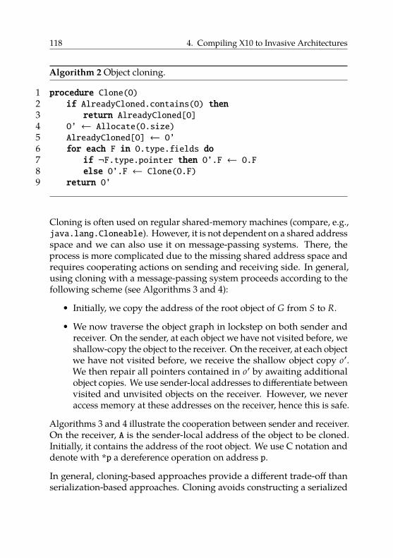
118 4. Compiling X10 to Invasive Architectures
Algorithm 2 Object cloning.
1 procedure Clone(O)2 if AlreadyCloned.contains(O) then3 return AlreadyCloned[O]4 O’ ← Allocate(O.size)5 AlreadyCloned[O] ← O’6 for each F in O.type.fields do7 if ¬F.type.pointer then O’.F ← O.F8 else O’.F ← Clone(O.F)9 return O’
Cloning is often used on regular shared-memory machines (compare, e.g.,java.lang.Cloneable). However, it is not dependent on a shared addressspace and we can also use it on message-passing systems. There, theprocess is more complicated due to the missing shared address space andrequires cooperating actions on sending and receiving side. In general,using cloning with a message-passing system proceeds according to thefollowing scheme (see Algorithms 3 and 4):
• Initially, we copy the address of the root object of G from S to R.
• We now traverse the object graph in lockstep on both sender andreceiver. On the sender, at each object we have not visited before, weshallow-copy the object to the receiver. On the receiver, at each objectwe have not visited before, we receive the shallow object copy o′.We then repair all pointers contained in o′ by awaiting additionalobject copies. We use sender-local addresses to differentiate betweenvisited and unvisited objects on the receiver. However, we neveraccess memory at these addresses on the receiver, hence this is safe.
Algorithms 3 and 4 illustrate the cooperation between sender and receiver.On the receiver, A is the sender-local address of the object to be cloned.Initially, it contains the address of the root object. We use C notation anddenote with *p a dereference operation on address p.
In general, cloning-based approaches provide a different trade-off thanserialization-based approaches. Cloning avoids constructing a serialized
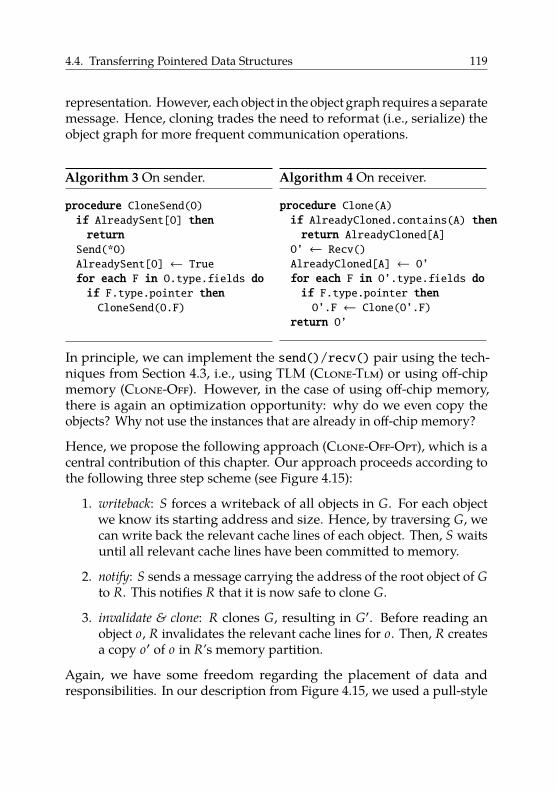
4.4. Transferring Pointered Data Structures 119
representation. However, each object in the object graph requires a separatemessage. Hence, cloning trades the need to reformat (i.e., serialize) theobject graph for more frequent communication operations.
Algorithm 3 On sender.
procedure CloneSend(O)if AlreadySent[O] thenreturnSend(*O)AlreadySent[O] ← Truefor each F in O.type.fields doif F.type.pointer thenCloneSend(O.F)
Algorithm 4 On receiver.
procedure Clone(A)if AlreadyCloned.contains(A) thenreturn AlreadyCloned[A]O’ ← Recv()AlreadyCloned[A] ← O’for each F in O’.type.fields doif F.type.pointer thenO’.F ← Clone(O’.F)
return O’
In principle, we can implement the send()/recv() pair using the tech-niques from Section 4.3, i.e., using TLM (Clone-Tlm) or using off-chipmemory (Clone-Off). However, in the case of using off-chip memory,there is again an optimization opportunity: why do we even copy theobjects? Why not use the instances that are already in off-chip memory?
Hence, we propose the following approach (Clone-Off-Opt), which is acentral contribution of this chapter. Our approach proceeds according tothe following three step scheme (see Figure 4.15):
1. writeback: S forces a writeback of all objects in G. For each objectwe know its starting address and size. Hence, by traversing G, wecan write back the relevant cache lines of each object. Then, S waitsuntil all relevant cache lines have been committed to memory.
2. notify: S sends a message carrying the address of the root object of Gto R. This notifies R that it is now safe to clone G.
3. invalidate & clone: R clones G, resulting in G′. Before reading anobject o, R invalidates the relevant cache lines for o. Then, R createsa copy o′ of o in R’s memory partition.
Again, we have some freedom regarding the placement of data andresponsibilities. In our description from Figure 4.15, we used a pull-style
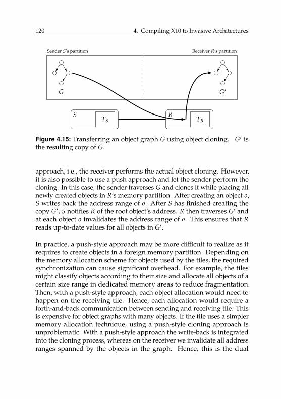
120 4. Compiling X10 to Invasive Architectures
TS TR
Sender S’s partition Receiver R’s partition
S R
G G′
Figure 4.15: Transferring an object graph G using object cloning. G′ isthe resulting copy of G.
approach, i.e., the receiver performs the actual object cloning. However,it is also possible to use a push approach and let the sender perform thecloning. In this case, the sender traverses G and clones it while placing allnewly created objects in R’s memory partition. After creating an object o,S writes back the address range of o. After S has finished creating thecopy G′, S notifies R of the root object’s address. R then traverses G′ andat each object o invalidates the address range of o. This ensures that Rreads up-to-date values for all objects in G′.
In practice, a push-style approach may be more difficult to realize as itrequires to create objects in a foreign memory partition. Depending onthe memory allocation scheme for objects used by the tiles, the requiredsynchronization can cause significant overhead. For example, the tilesmight classify objects according to their size and allocate all objects of acertain size range in dedicated memory areas to reduce fragmentation.Then, with a push-style approach, each object allocation would need tohappen on the receiving tile. Hence, each allocation would require aforth-and-back communication between sending and receiving tile. Thisis expensive for object graphs with many objects. If the tile uses a simplermemory allocation technique, using a push-style cloning approach isunproblematic. With a push-style approach the write-back is integratedinto the cloning process, whereas on the receiver we invalidate all addressranges spanned by the objects in the graph. Hence, this is the dual
4.4. Transferring Pointered Data Structures 121
situation to the pull-style approach (compare Algorithms 3 and 4). Ingeneral, as PGAS languages prefer one-sided communication, the push-style is preferable in this context.
The main difference between Clone-Off-Opt and serialization-basedapproaches is that Clone-Off-Opt avoids serialization and thus requiresno temporary buffers. Hence, it is cache-friendlier, as no temporary bufferspollute the cache.
For flat data structures, Clone-Off-Opt is equivalent to Ser-Off-Opt. Inthis case, there is no need for serialization on the sending side (“G � B”)and “deserialization” is equivalent to copying the single object, i.e., cloningit. Viewed this way, Clone-Off-Opt is a generalization of Ser-Off-Optfrom flat to pointered data structures. Viewed another way, Clone-Off-Opt augments the widely-used object-cloning technique with automaticwritebacks and invalidations to allow its use on non-cache-coherentsystems.
Correctness. At this point, we briefly discuss correctness of our ap-proach. We cannot offer any formal proofs, hence we only discuss thistopic informally.
In order to prevent data races, the object graph must not be modifiedconcurrently to the clone operation. With a push-style approach, thisrequires appropriate synchronization on the sender (the same applieswhen using serialization). The pull-style variant has one additionalcomplication. Here, the sender must wait until the receiver acknowledgesthat it has finished cloning the object graph. Hence, the necessarysynchronization involves a remote party and can therefore be moreexpensive.
It is also not intuitively clear that multiple concurrent transfers of thesame object graph do not cause issues. Let us first look at the situationwhere multiple receivers clone the same object graph G using pull-stylecloning. Hence, multiple writebacks of G can happen concurrently onthe sender. This is unproblematic, as writing back a non-dirty cache lineis a no-operation. Hence, multiple cores may compete to write back G,but as long as they properly synchronize afterwards, this does not causeissues.
122 4. Compiling X10 to Invasive Architectures
On the receiver, multiple invalidations of the same address range canhappen concurrently. For example, it is possible that core 1 invalidatesrange A, begins to read data from A, and then core 2 invalidates A again.However, this is unproblematic, as the next read request, even if it comesfrom core 1, fetches the data from memory again. The data at A muststill be the same as before, as otherwise there would be a data race in theprogram (as G was modified while being cloned). In general, multiplecompeting invalidations are not a problem, as we do not modify datain the sender’s partition. We only read from this memory area, hencecompeting transfers may invalidate the same cache line multiple times,which causes unnecessary costs, but is harmless.
With a push-style approach, the write-back issued by the sender is po-tentially problematic. Imagine that we create an object in the receiver’spartition and then issue a write-back of the relevant cache lines. If thereceiver modified data located at a different location in the same cacheline, we overwrite the receiver’s changes. However, we can easily preventthis problem by using reserved memory locations for writing to foreignmemory partitions (similar to MPI windows [Mes15, section 11.2]).
4.4.3. Related Work
The problem of transferring pointered data structures frequently ariseson architectures with physically separate address spaces, such as clustersof machines connected by a network. Various prior work explores thesimplification of transferring pointered data structures for programs usingMPI [GRR00; WBJ16]. The authors focus on assisting the programmerwith writing the necessary serialization routines and orchestrating thenecessary communication operations.
A similar problem arises in the context of platforms composed of a hostCPU and an accelerator, e.g., a GPU, with separate address spaces. TheOpenACC standard [Ope17] provides an API for offloading tasks fromCPU to accelerator. This involves copying data from the CPU’s addressspace to that of the accelerator. As of version 2.5 of the standard, OpenACConly allows transferring flat data structures. Beyer et al. [BOS14] reportthat, according to user feedback, this restriction is the most importantimpediment to porting interesting data structures and algorithms to
4.4. Transferring Pointered Data Structures 123
OpenACC. Beyer et al. propose a solution based on compiler directivesthat allow (semi-)automatic deep-copy support.
This body of work shows that transfers of pointered data structures occurfrequently and are important in real-world programs. In contrast tothis body of work, non-cache-coherent architectures do allow accesses toremote memory partitions, albeit without coherence guarantees, as weonly partition memory on a logical level.
In the context of non-cache-coherent architectures, our work is closely re-lated to the work on data transfers presented in Section 4.4.1. However, thisbody of work only considers flat data structures. In some cases [CHH11],authors mention pointered data structures, but use serialization with themessage-passing approach.
Regarding pointered data structures, it is interesting to look at the work ofPrescher et al. [PRN11; Rot+12] and Lyberis et al. [Lyb+12b]. Prescher et al.present MESH, a C++ framework for distributed shared memory thatsupports non-cache-coherent architectures. While X10 enforces a centralinstance for each object, i.e., each object exists on exactly one place, MESHallows choosing between different sharing models (object replication,central instance, and mixtures of both). However, MESH is library-basedas opposed to our compiler- and language-based approach. As such,existing software must be modified to be used with MESH. Moreover,their implementation requires a consistency-controller object per sharedobject and triggers additional communication for coherence management.We avoid this overhead, as we manage coherence in a more restrictedenvironment under control of the compiler.
Lyberis et al. present Myrmics [Lyb+12b], a memory-allocation schemebased on regions aimed at non-cache-coherent architectures. They observethat transferring pointered data structures using messages is an expensiveand complicated operation. As discussed above, low-level libraries, such asMPI, provide no dedicated support, i.e., the programmer must orchestratethe necessary serialization and deserialization.
Lyberis et al. propose to use regions, which are growable memory poolsthat contain objects. The Myrmics runtime system ensures that objectsallocated in such a region have a globally unique address across allcoherence domains. This means that if one coherence domain allocates an
124 4. Compiling X10 to Invasive Architectures
object at a globally valid address A, no other coherence domain allocatesan object at A even if that address is backed by distinct memory on differentcoherence domains.
Users can then allocate logically associated objects, e.g., each element of alinked list, in the same region. If a core from a different coherence domainrequires access to that data structure, Myrmics can transfer the wholeregion it is contained in as one block. As the object addresses, i.e., thepointers, are globally unique, even pointered data structures are validwithout modification after a transfer. Hence, the receiving domain canoperate locally on the copied data structure using the same pointers as thesending domain. Thus, Myrmics avoids the need for pointer translationcompletely.
However, using this approach requires program modifications. Specifi-cally, the programmer must identify data structures that may be sharedand use regions (and sub-regions) accordingly. Moreover, this approachrequires a virtual-memory subsystem. Otherwise, the same addressescannot refer to different memory locations on different domains.
Kumar et al. present HabaneroUPC++ [Kum+14], a C++ library thatenables an asynchronous PGAS programming style in C++. The libraryimplements constructs similar to those found in X10 (mainlyfinish, async,and at). The programmer must transfer necessary data manually.
Transferring non-contiguous data types is a frequent operation [KHS12].Therefore, MPI provides explicit support for specifying so-called deriveddata types [Mes15, chapter 4]. For example, derived data types allow todescribe the transfer of the first column of a matrix that is saved row-wisein memory. An MPI implementation can decide to pack this data into acontiguous format before the transfer. Alternatively, certain interconnecthardware supports the transfer of such derived data types directly frommemory (“zero copy”) [KHS12]. However, derived data types still requireregularly structured data and are unsuitable for irregular pointered datastructures. For the same reason, scatter/gather DMA transfers are notideal, as they can copy non-contiguous data structures but only makeshallow copies.
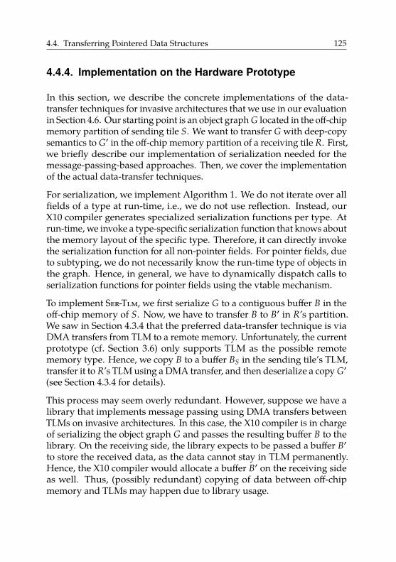
4.4. Transferring Pointered Data Structures 125
4.4.4. Implementation on the Hardware Prototype
In this section, we describe the concrete implementations of the data-transfer techniques for invasive architectures that we use in our evaluationin Section 4.6. Our starting point is an object graph G located in the off-chipmemory partition of sending tile S. We want to transfer G with deep-copysemantics to G′ in the off-chip memory partition of a receiving tile R. First,we briefly describe our implementation of serialization needed for themessage-passing-based approaches. Then, we cover the implementationof the actual data-transfer techniques.
For serialization, we implement Algorithm 1. We do not iterate over allfields of a type at run-time, i.e., we do not use reflection. Instead, ourX10 compiler generates specialized serialization functions per type. Atrun-time, we invoke a type-specific serialization function that knows aboutthe memory layout of the specific type. Therefore, it can directly invokethe serialization function for all non-pointer fields. For pointer fields, dueto subtyping, we do not necessarily know the run-time type of objects inthe graph. Hence, in general, we have to dynamically dispatch calls toserialization functions for pointer fields using the vtable mechanism.
To implement Ser-Tlm, we first serialize G to a contiguous buffer B in theoff-chip memory of S. Now, we have to transfer B to B′ in R’s partition.We saw in Section 4.3.4 that the preferred data-transfer technique is viaDMA transfers from TLM to a remote memory. Unfortunately, the currentprototype (cf. Section 3.6) only supports TLM as the possible remotememory type. Hence, we copy B to a buffer BS in the sending tile’s TLM,transfer it to R’s TLM using a DMA transfer, and then deserialize a copy G′
(see Section 4.3.4 for details).
This process may seem overly redundant. However, suppose we have alibrary that implements message passing using DMA transfers betweenTLMs on invasive architectures. In this case, the X10 compiler is in chargeof serializing the object graph G and passes the resulting buffer B to thelibrary. On the receiving side, the library expects to be passed a buffer B′
to store the received data, as the data cannot stay in TLM permanently.Hence, the X10 compiler would allocate a buffer B′ on the receiving sideas well. Thus, (possibly redundant) copying of data between off-chipmemory and TLMs may happen due to library usage.
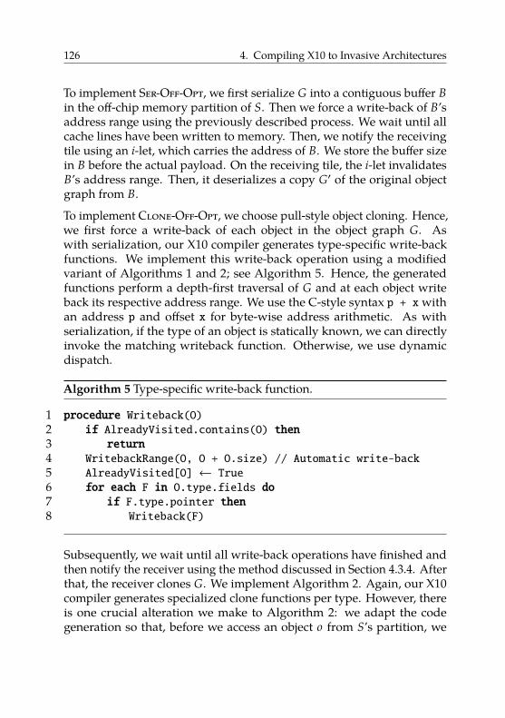
126 4. Compiling X10 to Invasive Architectures
To implement Ser-Off-Opt, we first serialize G into a contiguous buffer Bin the off-chip memory partition of S. Then we force a write-back of B’saddress range using the previously described process. We wait until allcache lines have been written to memory. Then, we notify the receivingtile using an i-let, which carries the address of B. We store the buffer sizein B before the actual payload. On the receiving tile, the i-let invalidatesB’s address range. Then, it deserializes a copy G′ of the original objectgraph from B.
To implement Clone-Off-Opt, we choose pull-style object cloning. Hence,we first force a write-back of each object in the object graph G. Aswith serialization, our X10 compiler generates type-specific write-backfunctions. We implement this write-back operation using a modifiedvariant of Algorithms 1 and 2; see Algorithm 5. Hence, the generatedfunctions perform a depth-first traversal of G and at each object writeback its respective address range. We use the C-style syntax p + xwithan address p and offset x for byte-wise address arithmetic. As withserialization, if the type of an object is statically known, we can directlyinvoke the matching writeback function. Otherwise, we use dynamicdispatch.
Algorithm 5 Type-specific write-back function.
1 procedure Writeback(O)2 if AlreadyVisited.contains(O) then3 return4 WritebackRange(O, O + O.size) // Automatic write-back5 AlreadyVisited[O] ← True6 for each F in O.type.fields do7 if F.type.pointer then8 Writeback(F)
Subsequently, we wait until all write-back operations have finished andthen notify the receiver using the method discussed in Section 4.3.4. Afterthat, the receiver clones G. We implement Algorithm 2. Again, our X10compiler generates specialized clone functions per type. However, thereis one crucial alteration we make to Algorithm 2: we adapt the codegeneration so that, before we access an object o from S’s partition, we
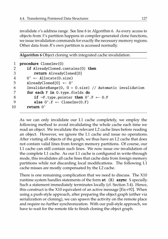
4.4. Transferring Pointered Data Structures 127
invalidate o’s address range. See line 6 in Algorithm 6. As every access toobjects from S’s partition happens in compiler-generated clone functions,we issue invalidation commands for exactly the necessary memory regions.Other data from R’s own partition is accessed normally.
Algorithm 6 Object cloning with integrated cache invalidation.
1 procedure CloneInv(O)2 if AlreadyCloned.contains(O) then3 return AlreadyCloned[O]4 O’ ← Allocate(O.size)5 AlreadyCloned[O] ← O’6 InvalidateRange(O, O + O.size) // Automatic invalidation7 for each F in O.type.fields do8 if ¬F.type.pointer then O’.F ← O.F9 else O’.F ← CloneInv(O.F)
10 return O’
As we can only invalidate our L1 cache completely, we employ thefollowing method to avoid invalidating the whole cache each time weread an object. We invalidate the relevant L2 cache lines before readingan object. However, we ignore the L1 cache and issue no operations.After visiting all objects of the graph, we thus have an L2 cache that doesnot contain valid lines from foreign memory partitions. Of course, ourL1 cache can still contain such lines. We now issue one invalidation ofthe complete L1 cache. As our L1 cache is configured in write-throughmode, this invalidates all cache lines that cache data from foreign memorypartitions while not discarding local modifications. The following L1cache misses are mostly compensated by the L2 cache.
There is one remaining complication that we need to discuss. The X10runtime system handles statements of the form at (B) async S specially.Such a statement immediately terminates locally (cf. Section 3.4). Hence,this construct is the X10 equivalent of an active message [Eic+92]. Whenusing a push-style approach, after preparing the object graph (either viaserialization or cloning), we can spawn the activity on the remote placeand require no further synchronization. With our pull-style approach, wehave to wait for the remote tile to finish cloning the object graph.
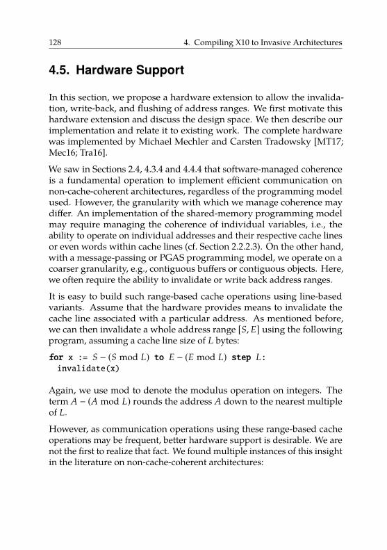
128 4. Compiling X10 to Invasive Architectures
4.5. Hardware Support
In this section, we propose a hardware extension to allow the invalida-tion, write-back, and flushing of address ranges. We first motivate thishardware extension and discuss the design space. We then describe ourimplementation and relate it to existing work. The complete hardwarewas implemented by Michael Mechler and Carsten Tradowsky [MT17;Mec16; Tra16].
We saw in Sections 2.4, 4.3.4 and 4.4.4 that software-managed coherenceis a fundamental operation to implement efficient communication onnon-cache-coherent architectures, regardless of the programming modelused. However, the granularity with which we manage coherence maydiffer. An implementation of the shared-memory programming modelmay require managing the coherence of individual variables, i.e., theability to operate on individual addresses and their respective cache linesor even words within cache lines (cf. Section 2.2.2.3). On the other hand,with a message-passing or PGAS programming model, we operate on acoarser granularity, e.g., contiguous buffers or contiguous objects. Here,we often require the ability to invalidate or write back address ranges.
It is easy to build such range-based cache operations using line-basedvariants. Assume that the hardware provides means to invalidate thecache line associated with a particular address. As mentioned before,we can then invalidate a whole address range [S, E] using the followingprogram, assuming a cache line size of L bytes:
for x := S − (S mod L) to E − (E mod L) step L:invalidate(x)
Again, we use mod to denote the modulus operation on integers. Theterm A − (A mod L) rounds the address A down to the nearest multipleof L.
However, as communication operations using these range-based cacheoperations may be frequent, better hardware support is desirable. We arenot the first to realize that fact. We found multiple instances of this insightin the literature on non-cache-coherent architectures:
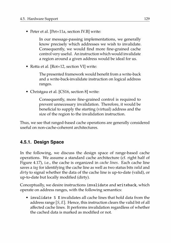
4.5. Hardware Support 129
• Peter et al. [Pet+11a, section IV.B] write:
In our message-passing implementations, we generallyknow precisely which addresses we wish to invalidate.Consequently, we would find more fine-grained cachecontrol very useful. An instruction which would invalidatea region around a given address would be ideal for us.
• Rotta et al. [Rot+12, section VI] write:
The presented framework would benefit from a write-backand a write-back-invalidate instruction on logical addressranges.
• Christgau et al. [CS16, section 8] write:
Consequently, more fine-grained control is required toprevent unnecessary invalidation. Therefore, it would bebeneficial to supply the starting (virtual) address and thesize of the region to the invalidation instruction.
Thus, we see that ranged-based cache operations are generally considereduseful on non-cache-coherent architectures.
4.5.1. Design Space
In the following, we discuss the design space of range-based cacheoperations. We assume a standard cache architecture (cf. right half ofFigure 4.17), i.e., the cache is organized in cache lines. Each cache linesaves a tag for identifying the cache line as well as two status bits valid anddirty to signal whether the data of the cache line is up-to-date (valid), orup-to-date but locally modified (dirty).
Conceptually, we desire instructions invalidate and writeback, whichoperate on address ranges, with the following semantics:
• invalidate S E invalidates all cache lines that hold data from theaddress range [S, E]. Hence, this instruction clears the valid bit of allaffected cache lines. It performs invalidation regardless of whetherthe cached data is marked as modified or not.
130 4. Compiling X10 to Invasive Architectures
• writeback S E writes back the contents of all cache lines that aremarked as modified and hold data from the address range [S, E].Hence, this instruction writes the data of the affected cache lines tothe next component in the memory hierarchy (i.e., the next cache orthe backing memory) and clears their modified (dirty) bits.
Ideally, these hypothetical instructions would run in one clock cycle.This is feasible in theory; however, the overhead would be significant.Essentially, such a fully parallel implementation of this concept wouldrequire two hardware comparators per cache line. These comparatorswould need to compare the address range given in the instruction againstthe tag of the respective cache line. In case the cached address is part ofthe address range, the respective action (invalidation or writeback) wouldbe triggered.
The area overhead of having two comparators per cache line seemsprohibitive. Typical addresses have 32 or 64 bits. We only need to comparethe number of bits occupied by the tag of a cache line. While the tagtypically has fewer bits, depending on the concrete cache structure, therequired comparators for that number of bits would still cause massivearea overhead.
Therefore, the designers of the Intel SCC chose a different approach. Theyintroduced an additional status bit, “MPBT” for “message-passing buffertype”19, for each cache line in the L1 cache. Software can mark memoryregions as MPBT memory with page granularity. Reads from MPBTmemory get cached in the L1 cache, but bypass the L2 cache. L1 cachelines holding data from MPBT memory have their respective MPBT bitset. The Intel SCC then provides the instruction CL1INVMB to invalidateall cache lines marked as MPBT in the L1 cache. This instruction runs inone clock cycle.
Unfortunately, there is no official documentation available about the inter-nal implementation of this instruction. We suspect that it is implementedusing 1-bit comparators, i.e., a single AND gate, per cache line. When acore executes the CL1INVMB instruction, the hardware checks the MPBT
19Named after the SCC’s on-chip memories (message-passing buffers, cf. Section 2.3.1). Thismemory type was designed to be used with message-passing buffer memory, but is notlimited to it, i.e., off-chip memory can be marked as MPBT as well [Mat+10].
4.5. Hardware Support 131
bit of all cache lines in parallel. For each cache line, if its MPBT bit is set,the hardware clears the valid bit of the respective cache line.
The Intel SCC does not provide a counterpart for writing back cache lines.Writes to MPBT memory do not get cached. However, the Intel SCC offersa “write-combine buffer” that aggregates writes. This buffer is flushedonce a full cache line has been written, or a different cache line is writtento. Thus, as long as applications are aware of this behavior, no explicitwriteback functionality is required.
While CL1INVMB allows the efficient invalidation of many cache lines atthe same time, it is imprecise. This may cause the unneeded invalidationof cache lines, resulting in unneeded memory accesses the next time theseaddresses are accessed. In fact, all statements from the authors quotedat the end of the previous section referenced the Intel SCC’s impreciseinvalidation instruction. Hence, this design sacrifices precision to achievethe goal of low running time (one clock cycle) with manageable areaoverhead.
In the following, we propose a different trade-off to approximate the idealof range-based cache operations that complete in one clock cycle. Ourproposal does not impede precision, i.e., it operates exactly on the cachelines belonging to a given address range. Instead, it compromises on therunning time: our proposed instruction takes one clock cycle (from theview of the processor) only in the best case; in the worst case it takesn clock cycles to operate on an address range spanning n cache lines.
4.5.2. Concept and Implementation
In the following, we present our concept and implementation of non-blocking range-based cache operations (or range operations for short).Our range operations offload the work to an enhanced cache controller.The underlying processor for our implementation is a Gaisler LEON 3,which implements the SPARC V8 ISA (cf. Section 3.6). However, neitherour concept nor our implementation are tied to this particular ISA ormicroarchitecture. We first present the instruction format we used andthen discuss our implementation of the cache-controller logic.
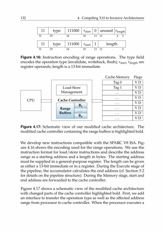
132 4. Compiling X10 to Invasive Architectures
11 type 111000 rstart 0 unused rlength31 29 24 18 13 12 4 0
11 type 111000 rstart 1 length31 29 24 18 13 12 0
Figure 4.16: Instruction encoding of range operations. The type fieldencodes the operation type (invalidate, writeback, flush); rstart, rlength areregister operands; length is a 13-bit immediate.
CPU Cache Controller
RangeBuffers
B1
. . .Bn
Load-StoreManagement
. . .
. . .
. . .
. . .
. . .
. . .Tag 1Tag 0
V DV DV DV DV DV DV DV D
Cache Memory Flags
Figure 4.17: Schematic view of our modified cache architecture. Themodified cache controller containing the range buffers is highlighted bold.
We develop new instructions compatible with the SPARC V8 ISA. Fig-ure 4.16 shows the encoding used for the range operations. We use theinstruction format for load/store instructions and describe the addressrange as a starting address and a length in bytes. The starting addressmust be supplied in a general-purpose register. The length can be givenas either a 13-bit immediate or in a register. During the Execute stage ofthe pipeline, the accumulator calculates the end address (cf. Section 5.2for details on the pipeline structure). During the Memory stage, start andend address are forwarded to the cache controller.
Figure 4.17 shows a schematic view of the modified cache architecturewith changed parts of the cache controller highlighted bold. First, we addan interface to transfer the operation type as well as the affected addressrange from processor to cache controller. When the processor executes a
4.5. Hardware Support 133
range operation, the processor pipeline is halted and control is transferredto the cache controller.
Then, we extend the cache controller with the ability to invalidate, writeback, or flush multiple cache lines. We implement our range operationsas multi-cycle instructions. Thus, we enhance the cache controller witha simple state machine that iterates over the address range specified bythe range operation. The cache controller can modify one cache line perclock cycle. Modification consists of performing an address lookup and,if a cache line is present, applying the respective operation. Hence, ittakes n clock cycles to apply a range operation spanning n cache lines.Essentially, this implements the loop from our introduction of Section 4.5in hardware.
However, our initial goal was an instruction that completes in one clockcycle. An obvious shortcoming of our current approach is that wehalt the processor until the range operation has finished, i.e., our rangeoperations are blocking. Can we drop this restriction and let the processorcontinue executing its program? For non-memory-related instructions,e.g., arithmetic or control-flow instructions, this is unproblematic20, asthese instructions do not require any cache functionality. However, load orstore instructions must perform cache lookups, which interferes with thelookups performed by our range operation logic. Additionally, they mightaccess an address that is part of the range the cache controller operates on.It is not obvious how to handle this situation correctly.
We propose the following design. In order to make our range operationsnon-blocking, we add range buffers Bi (cf. Figure 4.17) to the cache controller.Each range buffer holds a triple (s , e , t) of start address s, end address e,and operation type t (invalidation, writeback, or flush). Each time theprocessor executes a range operation on a range A, the cache controllerstores A along with its operation type in a range buffer as follows:
(i) If there is no free range buffer, we halt the processor until a bufferbecomes free.
(ii) If A overlaps with a range A′ already stored in another buffer, wehalt the processor until A′ has been processed.
(iii) Otherwise, we store A and its type in a free range buffer.
20Assuming a load/store architecture.
134 4. Compiling X10 to Invasive Architectures
Then, the processor continues executing the program. Every time itexecutes a load or store to an address D, the cache controller checksD against all stored ranges. We perform the checking in parallel usingseparate comparators for each range buffer. If D ∈ A for a stored range A,we halt the processor until the operation on A has finished. Otherwise,we perform a cache lookup as usual.
We call a clock cycle, during which the processor does not execute a loador store instruction, a spare cycle. We observe that, from the view of thecache controller, the cache is idle in every clock cycle where the processordoes not lookup an address. Our modified cache controller uses thesespare cycles to work on range operations. Hence, during every sparecycle, as long as there is at least one range A stored in a range buffer, thecache controller applies the respective operation to the next cache linerelevant for A, e.g., clearing a line’s valid bit for an invalidation. The cachecontroller keeps track of its progress using an internal register.
Therefore, it takes n spare cycles to apply an operation to a range span-ning n cache lines. In the best case, between the execution of two rangeoperations, there (i) are at least n spare cycles, and (ii) we execute nointerfering load or store instructions. Then, the first range operation takesonly one clock cycle from the view of the processor.
In summary, our proposed instructions inhabit a new point in the designspace of instructions that support software-managed coherence. Theyare precise and operate exactly on the given address range. To limit thearea overhead, they compromise on the running time and give no hardguarantee: execution can take 1 clock cycle, but may take up to n clockcycles for an address range that spans n cache lines21.
4.5.3. Related Work
As already mentioned in the introduction of Section 4.5, our range op-erations are related to the CL1INVMB instruction of the Intel SCC. Theexecution time of that instruction is guaranteed to be one clock cycle.However, it is imprecise as it invalidates all cache lines of a certain type.
21If the cache is shared between multiple cores, execution may take more than n cycles dueto interference with cache accesses of other cores.
4.6. Evaluation 135
Multiple authors [Pet+11a; Rot+12; CS16] criticize this lack of fine-grainedcontrol.
Range-based cache operations have been implemented before. Certainprocessors from the ARM11 family, e.g., the ARM1136J(F)-S processors,can perform invalidation, writeback, and flushing of address ranges via asystem control coprocessor [ARM09, section 3.3.17]. The range operationsare blocking. In contrast, our concept only requires an enhanced cachecontroller instead of a full-blown coprocessor. Additionally, we providenon-blocking range operations.
4.6. Evaluation
In the following, we evaluate some of the presented data-transfer tech-niques on our hardware prototype. First, we investigate transfers of flatdata structures and analyze the performance of Ac-Tlm and Ac-Off. Weuse a synthetic benchmark program. Then, we turn towards complex datastructures. Here, we analyze the performance of Clone-Off-Opt comparedto Ser-Tlm and Ser-Off-Opt. We first consider individual data transfersusing a synthetic benchmark and then look at distributed benchmarkprograms from an existing test suite. We perform all experiments on theinvasive hardware prototype. Finally, we investigate overhead and benefitof our cache controller extension.
4.6.1. Setup
We conducted all running time measurements on the invasive hardwareprototype described in Section 3.6. Recall that the architecture consists of4 tiles with 4 cores each. Each tile forms a coherence domain, where cachecoherence is guaranteed by a classical bus snooping protocol. However,there is no cache coherence between tiles. The tiles are connected by theinvasive network on chip [Hei+14] (NoC).
All cores are Gaisler SPARC V8 LEON 3 [Cob17b; SPA92] processors. Eachprocessor has a private 16 KiB 2-way instruction cache with a cache linesize of 32 bytes and a private 8 KiB 2-way write-through L1 data cache

136 4. Compiling X10 to Invasive Architectures
with a cache line size of 16 bytes. Additionally, the 4 cores of each tileshare a 64 KiB 4-way write-back L2 cache with a cache line size of 32 bytes.Each tile has 8 MiB of SRAM-based on-chip memory. Tile 3 has 256 MiB ofDDR3 memory, used as shared memory, attached to its internal bus. Wedo not execute any application code on this tile during our experiments.Hence, all cores used by our applications access the off-chip memory viathe NoC.
We only use two compute tiles to increase stability in case of concurrentDMA transfers22. As two tiles still require inter-tile data transfers, two tilesare sufficient for our purposes. The hardware design was synthesized to aCHIPit Platinum system [Syn15], a multi-FPGA platform based on XilinxVirtex 5 LX 330 FPGAs23.
On the software side, we use X10 as our PGAS programming language. Weuse the modified X10 compiler (cf. Section 3.5) based on version 2.324. Wecompiled all programs using the -O3 flag. We use OctoPOS (cf. Section 3.3)as our operating system25. We use the perf variant of OctoPOS, whichresults in an optimized build with disabled assertions and without sanitychecks. We used the hwcpy variant, which uses hardware-accelerated datatransfers between TLMs.
We use a conservative stop-the-world garbage collector [BW88]26 formemory management on each tile. We compiled all C componentsof our software stack using the official SPARC toolchain provided byGaisler [Cob15a], which is based on GCC 4.4.2. We used GRMON [Cob17a]version v2.0.69.1 to load and run binaries27. We used temci [Bec16] version0.7.9 to analyze some of our benchmark data. As we work on customhardware, we did not use any benchmark-data acquisition tools providedby temci; we only used it to visualize and analyze already collectedbenchmark data.
22At the time of writing, these problems have been fixed in current hardware revisions.23We used hardware revision 2016_04_18 from April 18, 2016.24We used Git revision 1faf26498de2eb3e25f85bdc0e74a5f9b816ab59.25We used Git revision 510073385ec96b75fafdd91c0aac894f99357315. This revision is
based on Git revision 741f34079a5e968d6002b7e8d3270a2b0f58fe07, but adapts someparameters, such as using fewer but larger contexts, i.e., stacks, for i-lets.
26We used Git revision 5f1b891d30626dc4074686aa2ea061356c635b93.27Extended with grmon_toolsGit revision 65189723b9cee70505a66ceff2244ed9bd826524.
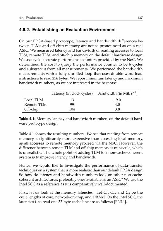
4.6. Evaluation 137
4.6.2. Establishing an Evaluation Environment
On our FPGA-based prototype, latency and bandwidth differences be-tween TLMs and off-chip memory are not as pronounced as on a realASIC. We measured latency and bandwidth of reading accesses to localTLM, remote TLM, and off-chip memory on the default hardware design.We use cycle-accurate performance counters provided by the NoC. Wedetermined the cost to query the performance counter to be 6 cyclesand substract it from all measurements. We performed the bandwidthmeasurements with a fully unrolled loop that uses double-word loadinstructions to read 256 bytes. We report minimum latency and maximumbandwidth numbers, as we are interested in the best case.
Latency (in clock cycles) Bandwidth (in MiB s−1)Local TLM 13 19.0Remote TLM 99 4.0Off-chip 104 3.8
Table 4.1: Memory latency and bandwidth numbers on the default hard-ware prototype design.
Table 4.1 shows the resulting numbers. We see that reading from remotememory is significantly more expensive than accessing local memory,as all accesses to remote memory proceed via the NoC. However, thedifference between remote TLM and off-chip memory is miniscule, whichis unrealistic. The whole point of adding TLM to a non-cache-coherentsystem is to improve latency and bandwidth.
Hence, we would like to investigate the performance of data-transfertechniques on a system that is more realistic than our default FPGA design.So how do latency and bandwidth numbers look on other non-cache-coherent architectures, preferably ones available as an ASIC? We use theIntel SCC as a reference as it is comparatively well-documented.
First, let us look at the memory latencies. Let Cc , Cn , and Cd be thecycle lengths of core, network-on-chip, and DRAM. On the Intel SCC, thelatencies L to read one 32-byte cache line are as follows [PN14].
138 4. Compiling X10 to Invasive Architectures
• Reading from local on-chip memory: Llocal � 45 · Cc + 8 · Cn .• Reading from remote on-chip memory: Lremote � 45 · Cc + k · 8 · Cn .• Reading from DRAM: LDRAM � 40 · Cc + k · 8 · Cn + 46 · Cd .
Here, k is the number of hops in the network-on-chip from source todestination (0 ≤ k ≤ 8).
However, computing these latencies is not straightforward, as the IntelSCC’s cores, network-on-chip, and DRAM can be clocked at differentfrequencies. The possible frequencies (in MHz) are fc ∈ {533, 800},fn ∈ {800, 1600}, and fd ∈ {800, 1066}. We assume the recommendedsetting of fc � 533 MHz, fn � 800 MHz, and fd � 800 MHz, which is alsoused in most papers. The latencies compute to (assuming k � 4 as anaverage and rounding up the values):
• Llocal � 90 ns• Lremote � 110 ns• LDRAM � 165 ns
Hence, accessing DRAM on the Intel SCC has a roughly 50% higherlatency than accessing on-chip memory. However, the SCC is only aprototype chip as well. Its core clock of 533 MHz is low in comparisonto current microprocessors. Therefore, on a non-prototype chip the coreand network-on-chip frequencies would be several times higher thanthe DRAM frequency. This would likely increase the latency differencebetween accessing on-chip and off-chip memory even further.
Second, let us look at bandwidth on the Intel SCC. Van Tol et al. [Tol+11]report bandwidth measurements on the Intel SCC, also with the standardfrequency settings. The Intel SCC has four memory controllers resulting ina theoretical peak transfer rate of 6.4 GiB s−1. Van Tol et al. determine themaximum bandwidth load generated by one core to be about 107 MiB s−1
when reading from off-chip memory (and not from a cache). For the casewhen 48 cores read from off-chip memory at the same time, van Tol et al.measure a peak bandwidth requirement of 5.9 GiB s−1. Hence, even 48cores cannot saturate the available memory bandwidth. Again, thisis unrealistic, as current multi-core processors can easily saturate thememory bandwidth with far fewer than 48 cores. Hence, the Intel SCCcan serve as a guideline, but is not an ideal example of realistic latency orbandwidth numbers.

4.6. Evaluation 139
Besides the lack of clear target numbers for latency and bandwidth,also emulating more realistic hardware on an FPGA is challenging. Forexample, we cannot arbitrarily reduce the clock frequency of our DRAMchips as they are very sensitive to timing, especially regarding the necessaryDRAM refresh cycles. On the other hand, increasing the clock frequencyof the cores is not possible either due to critical-path lengths and timingconstraints.
Hence, we focus on one aspect that we can influence comparatively easily:latency. We modified the default hardware design to artifically increaseoff-chip memory latency by 1000 clock cycles28. We consciously chose thehigh penalty of 1000 clock cycles to clearly separate the default designfrom the modified design. In the modified design, additional logic hasbeen inserted into the network adapter of each compute tile. If a core (orthe L2 cache) issues a load or store request to an address that is backed byoff-chip memory (i.e., DRAM), the network adapter artificially delays theserving of this request by 1000 clock cycles. All other requests proceednormally. Hence, the delay is implemented on the requesting side ofmemory accesses.
In the following, we call the default hardware variant Hw-Default29, andthe modified hardware variant with artificial off-chip delay Hw-Delay30.
Latency [clock cycles] Bandwidth [MiB s−1]Local TLM 13 19.0Remote TLM 99 4.0Off-chip 1104 (+1000) 0.7 (−3.1)
Table 4.2: Memory latency and bandwidth numbers on Hw-Delay withartifical DRAM latency. We list the absolute change compared toHw-Default in parentheses.
Table 4.2 shows latency and bandwidth numbers on Hw-Delay. Weobserve exactly the artificial latency penalty of 1000 clock cycles for off-
28Sven Rheindt provided the modified hardware design.29We used hardware revision 2016_04_18 dated from April 18, 2016.30We used hardware revision 2016_04_18_delay_ddr_ls dated from December 7, 2017
based on the design from April 18, 2016.
140 4. Compiling X10 to Invasive Architectures
chip accesses. At the same time, the increased latency also significantlyreduces the bandwidth of off-chip accesses.
Now, we we have two designs that represent extremes: Hw-Default, whereoff-chip memory is almost as fast as remote TLMs, and Hw-Delay, whereoff-chip memory is significantly slower, even more so than on the IntelSCC. To investigate the behavior of our data transfer approaches at thesetwo extremes, we perform all following benchmarks on both hardwaredesigns. As the hardware designs are functionally equivalent, we can runthe same binaries on both hardware variants. For each benchmark, thisprovides us with lower and upper bounds for the running times. Therunning time on a realistic system would likely fall somewhere in thisrange, depending on the parameters of its memory system.
4.6.3. Block-Based Data Transfers
We now compare our implementations of Ac-Tlm to Ac-Off on the invasivehardware prototype. We use a synthetic X10 benchmark program31 thatissues one-sided copy operations via Rail.asyncCopy() to copy data fromthe sender’s off-chip memory partition to the receiver’s off-chip memorypartition. We vary the size of the transferred memory block from 25 bytesto 218 bytes. We measure running times using cycle-accurate countersprovided by the NoC and use 25 as the divisor to compute microseconds(as our cores run at 25 MHz). We repeat each experiment at least 50 times;for small transfer sizes we use 200 iterations to stabilize measurements.We verify the received data after the transfer; this verification step is notpart of the measured running time.
We expect to see that Ac-Off is faster at least for large transfers. In thiscase, taking the detour via TLM should be slower. For small transfers,the situation is not as clear. Here, if data is served from cache to TLM,transferred to another TLM, and then again cached, blocking off-chipmemory accesses are completely avoided. Hence, we might see a break-even point, i.e., Ac-Off is faster for memory blocks larger than somethreshold.
31We used Git revision 0888071439f58a06c116fd56af46bd4c74b41905.
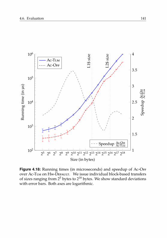
4.6. Evaluation 141
25 26 27 28 29 210 211 212 213 214 215 216 217 218102
103
104
105
106
L1$
size
L2$
size
Size (in bytes)
Runn
ing
time
(inµs
)
Ac-TlmAc-Off
1
1.5
2
2.5
3
3.5
4
Spee
dup
Ac-
Off
Ac-
Tlm
Speedup Ac-OffAc-Tlm
Figure 4.18: Running times (in microseconds) and speedup of Ac-Offover Ac-Tlm on Hw-Default. We issue individual block-based transfersof sizes ranging from 25 bytes to 218 bytes. We show standard deviationswith error bars. Both axes are logarithmic.
142 4. Compiling X10 to Invasive Architectures
Figure 4.18 shows the running times of both approaches, as well as thecomputed speedups of Ac-Off over Ac-Tlm using Hw-Default. Here,directly transferring the data to off-chip memory is always faster thangoing via TLMs. For small buffers, the standard error is quite high, but stillallows us to state that Ac-Off is about 2× faster than Ac-Tlm. The speedupthen reaches its maximum of about 3.5× for transfers of 1 KiB. Afterexceeding the size of the L1 cache, the speedup decreases significantly.Interestingly, as we reach the size of the L2 cache, the speedup increases.We do not have a convincing theory to explain this observation.
Figure 4.19 shows the running times of both approaches and the computedspeedups on Hw-Delay. We see that for buffer sizes less than 28 bytes,the standard deviations are too high to declare one of the approachessuperior. For buffers of size 29 bytes and higher, Ac-Off is about 2.5×–3×faster than Ac-Tlm. As we exceed the size of the L1 cache, the speedupdeclines sharply and stays between 1.5× and 2×. Suprisingly, we do notobserve a break-even point. This may be due to the requirement of ourplatform to copy data to TLM before issuing DMA transfers.
These speedup numbers agree with the numbers reported by Christ-gau et al. [CS16] who measured a speedup of 2× to 5× on the IntelSCC using one-sided communication via off-chip memory relative toon-chip-based message passing. They performed their measurements inthe context of MPI one-sided communication using MPI_Put. Just as inour experiment, the one-sided version was always faster, even for smalltransfers.
4.6.4. Transfers of Pointered Data Structures
In the following, we look at transfers of pointered data structures. Weselect a subset of the presented data-transfer techniques and analyzethe performance of Clone-Off-Opt compared to Ser-Tlm and Ser-Off-Opt. Comparing to Ser-Tlm shows whether using on-chip memory isworthwhile. Comparing to Ser-Off-Opt shows whether it is worthwhileto avoid serialization.
We first consider individual data transfers using synthetic benchmarksand then look at distributed benchmark programs from an existing test
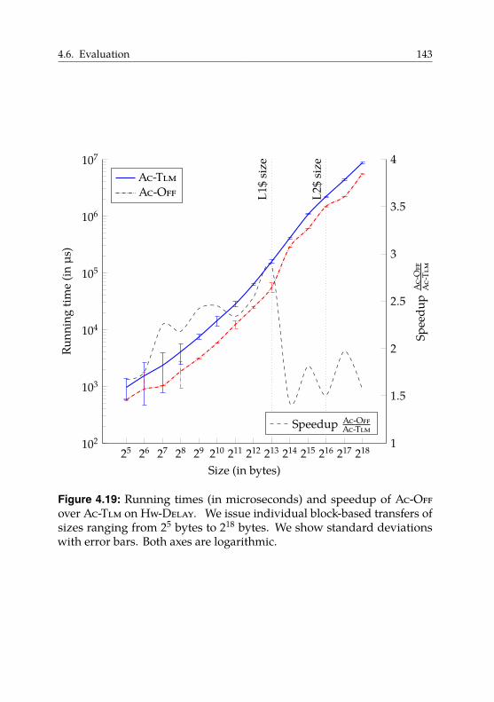
4.6. Evaluation 143
25 26 27 28 29 210 211 212 213 214 215 216 217 218102
103
104
105
106
107
L1$
size
L2$
size
Size (in bytes)
Runn
ing
time
(inµs
)
Ac-TlmAc-Off
1
1.5
2
2.5
3
3.5
4
Spee
dup
Ac-
Off
Ac-
Tlm
Speedup Ac-OffAc-Tlm
Figure 4.19: Running times (in microseconds) and speedup of Ac-Offover Ac-Tlm on Hw-Delay. We issue individual block-based transfers ofsizes ranging from 25 bytes to 218 bytes. We show standard deviationswith error bars. Both axes are logarithmic.

144 4. Compiling X10 to Invasive Architectures
suite. For execution on the invasive hardware prototype, we used thescripts developed as part of the octopos-testsuite-infrastructureproject32. We repeated each experiment 50 times unless otherwise noted.As our software has full control over the hardware and there is noresource virtualization, the running time was highly deterministic. Thestandard deviation for all runs was below 0.1%, so we omit giving standarddeviations and report minimum running times. The Ser-Tlm approachdid not have to split messages in our experiments as our TLMs provideample size.
4.6.4.1. Individual Data Transfers
First, we look at individual transfers using a synthetic benchmark33. Wetransfer a circular doubly linked list and vary two parameters: the numberof list elements n and the size per list element E. We create a new datastructure for each transfer. We compare Clone-Off-Opt to Ser-Tlm andSer-Off-Opt. We first perform experiments on Hw-Default and then onHw-Delay.
Regarding the presentation of our benchmark results, we decided to usea series of tables. We have a two-dimensional parameter space (n andE), running times for three approaches, and the computed speedups.We tried using a visualization as in Figures 4.18 and 4.19. However, theresulting three-dimensional plot was difficult to read and understand.Hence, we use four tables. Each has our two-dimensional parameterspace as rows and columns, and as table entries shows the computedspeedup numbers for Clone-Off-Opt over either Ser-Tlm or Ser-Off-Opt on either Hw-Default or Hw-Delay, resulting in four tables. In allfollowing experiments, we measure speedups for lists from n � 1 to 256elements with element sizes E ranging from 64 bytes up to 4 KiB.
On Hw-Default, we expect Clone-Off-Opt to be superior to Ser-Tlm,except maybe for certain medium-sized object graphs. For these graphs,their serialized representation would fit into the cache, hence no blockingoff-chip memory access occur. Furthermore, the hardware-accelerated
32We used Git revision 4edfb2558b8c5bde5fe18ba76da86ac6cd50538c.33We used Git revision 1faf26498de2eb3e25f85bdc0e74a5f9b816ab59.
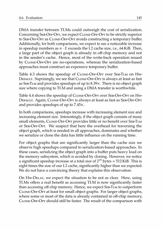
4.6. Evaluation 145
DMA transfer between TLMs could outweigh the cost of serialization.Concerning Ser-Off-Opt, we expect Clone-Off-Opt to be strictly superiorto Ser-Off-Opt as Clone-Off-Opt avoids constructing a temporary buffer.Additionally, for both comparisons, we expect to see a noticeable increasein speedup numbers as n · E exceeds the L2 cache size, i.e., 64 KiB. Then,a large part of the object graph is already in off-chip memory and notin the sender’s cache. Hence, most of the write-back operation issuedby Clone-Off-Opt are no-operations, whereas the serialization-basedapproaches must construct an expensive temporary buffer.
Table 4.3 shows the speedup of Clone-Off-Opt over Ser-Tlm on Hw-Default. Suprisingly, we see that Clone-Off-Opt is always at least as fastas Ser-Tlm and provides speedups of up to 8.39×. There is no object graphsize where copying to TLM and using a DMA transfer is worthwhile.
Table 4.4 shows the speedup of Clone-Off-Opt over Ser-Off-Opt on Hw-Default. Again, Clone-Off-Opt is always at least as fast as Ser-Off-Optand provides speedups of up to 7.45×.
In both comparisons, speedups increase with increasing element size andincreasing element size. Interestingly, if the object graph consists of manysmall elements, Clone-Off-Opt provides little or no benefit over Ser-Tlmor Ser-Off-Opt. We suspect that here the overhead for traversing theobject graph, which is needed in all approaches, dominates and whetherwe serialize or clone the data has little influence on the running time.
For object graphs that are significantly larger than the cache size weobserve high speedups compared to serialization-based approaches. Inthese cases, serializing the object graph into a buffer puts heavy load onthe memory subsystem, which is avoided by cloning. However, we noticea significant speedup increase at a total size of 219 bytes � 512 KiB. This iseight times the size of our L2 cache, significantly higher than we expected.We do not have a convincing theory that explains this observation.
On Hw-Delay, we expect the situation to be not as clear. Here, usingTLMs offers a real benefit as accessing TLM is now significantly fasterthan accessing off-chip memory. Hence, we expect Ser-Tlm to outperformClone-Off-Opt at least for small object graphs. For larger object graphs,where some or most of the data is already contained in off-chip memory,Clone-Off-Opt should still be faster. The result of the comparison with
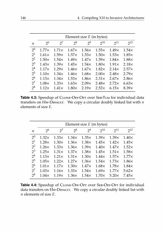
146 4. Compiling X10 to Invasive Architectures
Element size E (in bytes)n 26 27 28 29 210 211 212
20 1.77× 1.71× 1.67× 1.56× 1.55× 1.49× 1.54×21 1.61× 1.59× 1.57× 1.53× 1.50× 1.53× 1.85×22 1.50× 1.54× 1.49× 1.47× 1.59× 1.84× 1.88×23 1.43× 1.39× 1.45× 1.54× 1.80× 1.91× 2.18×24 1.17× 1.29× 1.46× 1.67× 1.82× 2.14× 2.57×25 1.10× 1.34× 1.46× 1.68× 2.00× 2.48× 2.79×26 1.13× 1.34× 1.53× 1.86× 2.31× 2.67× 2.86×27 1.08× 1.33× 1.63× 2.09× 2.48× 2.72× 6.63×28 1.12× 1.41× 1.80× 2.19× 2.52× 6.15× 8.39×
Table 4.3: Speedup of Clone-Off-Opt over Ser-Tlm for individual datatransfers on Hw-Default. We copy a circular doubly linked list with nelements of size E.
Element size E (in bytes)n 26 27 28 29 210 211 212
20 1.32× 1.33× 1.34× 1.35× 1.39× 1.39× 1.40×21 1.28× 1.30× 1.36× 1.38× 1.45× 1.42× 1.45×22 1.26× 1.33× 1.36× 1.39× 1.40× 1.47× 1.52×23 1.25× 1.31× 1.37× 1.38× 1.45× 1.51× 1.58×24 1.13× 1.21× 1.31× 1.30× 1.44× 1.57× 1.77×25 1.05× 1.22× 1.27× 1.36× 1.54× 1.73× 1.86×26 1.01× 1.17× 1.30× 1.47× 1.68× 1.78× 1.84×27 1.03× 1.16× 1.33× 1.54× 1.69× 1.77× 5.62×28 1.04× 1.19× 1.36× 1.54× 1.70× 5.20× 7.45×
Table 4.4: Speedup of Clone-Off-Opt over Ser-Off-Opt for individualdata transfers on Hw-Default. We copy a circular doubly linked list withn elements of size E.
4.6. Evaluation 147
Ser-Off-Opt is difficult to predict. Both approaches use off-chip memoryto transfer data. The only difference is that Ser-Off-Opt writes a singlecontiguous block to memory, whereas Clone-Off-Opt writes (potentiallymany) smaller objects.
Table 4.5 shows the speedup of Clone-Off-Opt over Ser-Tlm on Hw-Delay.As expected, the situation is not as clear as before. For small object graphsof size less than 214 � 16 KiB, Ser-Tlm is faster than Clone-Off-Opt byroughly a factor of 2. We observe the highest speedup of Ser-Tlm (orlowest speedup for Clone-Off-Opt) for n � 32 and E � 64. Here, thelatency and bandwidth advantages of TLM seem to be most pronounced.For large object graphs, Clone-Off-Opt is still significantly faster thanSer-Tlm and provides speedups of up to 8.36×.
Table 4.6 shows the speedup of Clone-Off-Opt over Ser-Off-Opt on Hw-Delay. Now, Ser-Off-Opt is sometimes a bit faster than Clone-Off-Optbut not by a large margin. We again observe the highest speedup ofSer-Off-Opt (or lowest speedup for Clone-Off-Opt) for n � 32 and E � 64.We suspect that the speedup of Ser-Off-Opt relative to Clone-Off-Optis due to more predictable access behavior on the receiver. For Ser-Off-Opt, the receiver reads the contiguous serialized representation fromoff-chip memory. Hence, as the access behavior is predictable, manyload instructions are cache hits. In contrast, Clone-Off-Opt traverses theobject graph on the receiver. The objects may be scattered across off-chipmemory, which may lead to a higher number of cache misses. For largeobject graphs, Clone-Off-Opt significantly outperforms Ser-Off-Opt andprovides speedups of up to 7.54×.
Again, in both comparisons speedups increase with increasing elementsize and increasing total data size. The significant speedup increase isagain at a total size of 219 bytes � 512 KiB, for which we cannot offer anexplanation.
Our results show that, in general, cloning is beneficial for large objectgraphs. If the speed difference between TLM and off-chip memory is largeenough, we observe a break-even point P. For object graphs larger thanthis P, cloning is the fastest approach. For object graphs smaller than P,exploiting TLM offers a performance advantage.
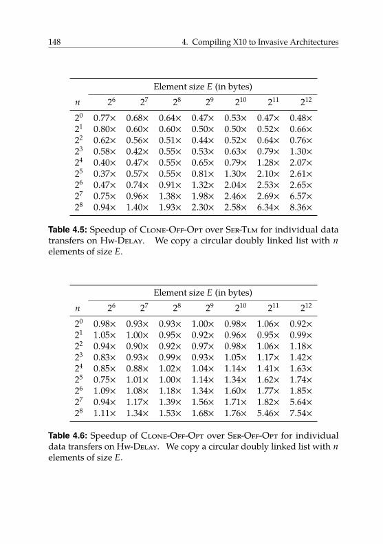
148 4. Compiling X10 to Invasive Architectures
Element size E (in bytes)n 26 27 28 29 210 211 212
20 0.77× 0.68× 0.64× 0.47× 0.53× 0.47× 0.48×21 0.80× 0.60× 0.60× 0.50× 0.50× 0.52× 0.66×22 0.62× 0.56× 0.51× 0.44× 0.52× 0.64× 0.76×23 0.58× 0.42× 0.55× 0.53× 0.63× 0.79× 1.30×24 0.40× 0.47× 0.55× 0.65× 0.79× 1.28× 2.07×25 0.37× 0.57× 0.55× 0.81× 1.30× 2.10× 2.61×26 0.47× 0.74× 0.91× 1.32× 2.04× 2.53× 2.65×27 0.75× 0.96× 1.38× 1.98× 2.46× 2.69× 6.57×28 0.94× 1.40× 1.93× 2.30× 2.58× 6.34× 8.36×
Table 4.5: Speedup of Clone-Off-Opt over Ser-Tlm for individual datatransfers on Hw-Delay. We copy a circular doubly linked list with nelements of size E.
Element size E (in bytes)n 26 27 28 29 210 211 212
20 0.98× 0.93× 0.93× 1.00× 0.98× 1.06× 0.92×21 1.05× 1.00× 0.95× 0.92× 0.96× 0.95× 0.99×22 0.94× 0.90× 0.92× 0.97× 0.98× 1.06× 1.18×23 0.83× 0.93× 0.99× 0.93× 1.05× 1.17× 1.42×24 0.85× 0.88× 1.02× 1.04× 1.14× 1.41× 1.63×25 0.75× 1.01× 1.00× 1.14× 1.34× 1.62× 1.74×26 1.09× 1.08× 1.18× 1.34× 1.60× 1.77× 1.85×27 0.94× 1.17× 1.39× 1.56× 1.71× 1.82× 5.64×28 1.11× 1.34× 1.53× 1.68× 1.76× 5.46× 7.54×
Table 4.6: Speedup of Clone-Off-Opt over Ser-Off-Opt for individualdata transfers on Hw-Delay. We copy a circular doubly linked list with nelements of size E.
4.6. Evaluation 149
4.6.4.2. Distributed Kernel Benchmarks
We now compare the running times of X10 applications using Ser-Tlm,Ser-Off-Opt, and Clone-Off-Opt. We use the X10 programs from theIMSuite benchmark suite [GN15] as our test inputs. IMSuite consists of12 programs that implement popular, mostly graph-based distributedalgorithm kernels. More specifically, the programs are:
• BF, an implementation of the Bellman-Ford algorithm;• DST, which computes shortest routes according to Dijktra’s method;• BY, a solver for the Byzantine generals’ problem;• DR, which computes a routing table for a graph;• DS, which finds a dominating set;• KC, which partitions the nodes of a network into committees of size
at most k;• MIS, which computes a maximal independent set of a set of nodes;• LCR, HS, DP, which all implement leader election algorithms with
different graph constraints;• MST, which computes a minimum spanning tree; and• VC, which colors the nodes of a tree with three colors.
Being distributed in nature means that, when run on an invasive archi-tecture, the programs must communicate between tiles. Hence, they area good fit for assessing data-transfer performance. The sizes of the testprograms range from 300 loc to 1000 loc.
We use the iterative X10-FA configuration of the benchmark programswith the input data set of size 64. We use the running time measurementinfrastructure already present in the programs. We modified the programsso that they contain their input data as our prototype platform does notprovide a file system. Input data is read during the initialization phase,which is not included in the running time measurements.
IMSuite contains implementations of each algorithm in two languages:X10 and Habanero Java [Cav+11]. Habanero Java extends Java withfeatures very similar to those found in X10. As both languages aim toincrease programmer productivity, the IMSuite authors decided againstwriting highly tuned implementations of the respective algorithms. In-
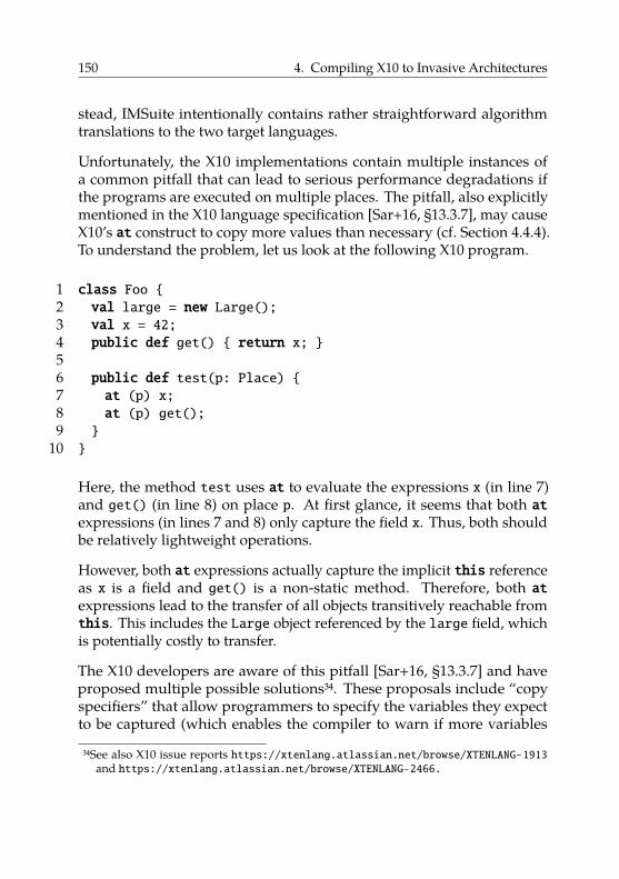
150 4. Compiling X10 to Invasive Architectures
stead, IMSuite intentionally contains rather straightforward algorithmtranslations to the two target languages.
Unfortunately, the X10 implementations contain multiple instances ofa common pitfall that can lead to serious performance degradations ifthe programs are executed on multiple places. The pitfall, also explicitlymentioned in the X10 language specification [Sar+16, §13.3.7], may causeX10’s at construct to copy more values than necessary (cf. Section 4.4.4).To understand the problem, let us look at the following X10 program.
1 class Foo {2 val large = new Large();3 val x = 42;4 public def get() { return x; }56 public def test(p: Place) {7 at (p) x;8 at (p) get();9 }
10 }
Here, the method test uses at to evaluate the expressions x (in line 7)and get() (in line 8) on place p. At first glance, it seems that both atexpressions (in lines 7 and 8) only capture the field x. Thus, both shouldbe relatively lightweight operations.
However, both at expressions actually capture the implicit this referenceas x is a field and get() is a non-static method. Therefore, both atexpressions lead to the transfer of all objects transitively reachable fromthis. This includes the Large object referenced by the large field, whichis potentially costly to transfer.
The X10 developers are aware of this pitfall [Sar+16, §13.3.7] and haveproposed multiple possible solutions34. These proposals include “copyspecifiers” that allow programmers to specify the variables they expectto be captured (which enables the compiler to warn if more variables
34See also X10 issue reports https://xtenlang.atlassian.net/browse/XTENLANG-1913and https://xtenlang.atlassian.net/browse/XTENLANG-2466.
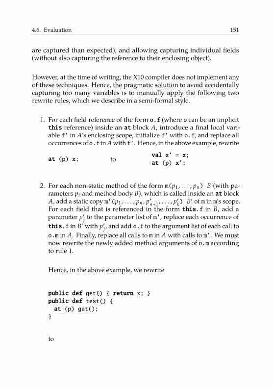
4.6. Evaluation 151
are captured than expected), and allowing capturing individual fields(without also capturing the reference to their enclosing object).
However, at the time of writing, the X10 compiler does not implement anyof these techniques. Hence, the pragmatic solution to avoid accidentallycapturing too many variables is to manually apply the following tworewrite rules, which we describe in a semi-formal style.
1. For each field reference of the form o.f (where o can be an implicitthis reference) inside an at block A, introduce a final local vari-able f’ in A’s enclosing scope, initialize f’ with o.f, and replace alloccurrences of o.f in A with f’. Hence, in the above example, rewrite
at (p) x; to val x’ = x;at (p) x’;
2. For each non-static method of the form m(p1 , . . . , pn) B (with pa-rameters pi and method body B), which is called inside an at blockA, add a static copy m’(p1 , . . . , pn , p′n+1 , . . . , p
′k) B′ of m in m’s scope.
For each field that is referenced in the form this.f in B, add aparameter p′j to the parameter list of m’, replace each occurrence ofthis.f in B′ with p′j , and add o.f to the argument list of each call too.m in A. Finally, replace all calls to m in A with calls to m’. We mustnow rewrite the newly added method arguments of o.m accordingto rule 1.
Hence, in the above example, we rewrite
public def get() { return x; }public def test() {at (p) get();}
to
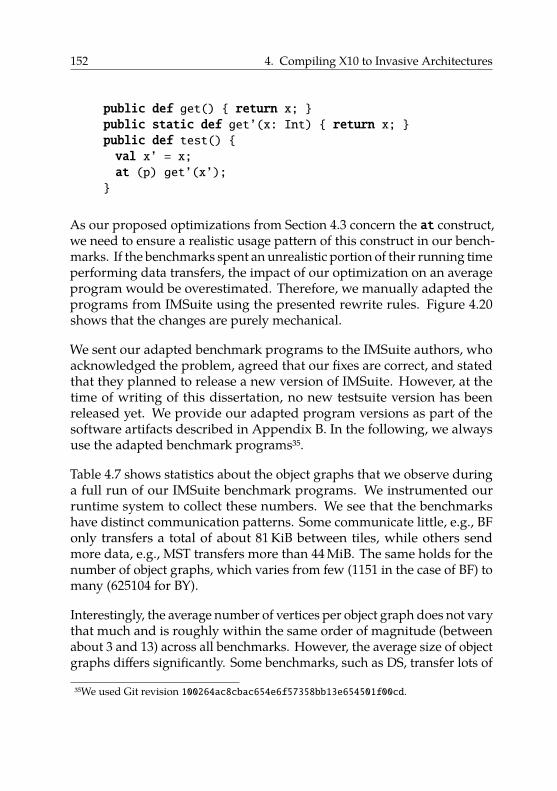
152 4. Compiling X10 to Invasive Architectures
public def get() { return x; }public static def get’(x: Int) { return x; }public def test() {val x’ = x;at (p) get’(x’);}
As our proposed optimizations from Section 4.3 concern the at construct,we need to ensure a realistic usage pattern of this construct in our bench-marks. If the benchmarks spent an unrealistic portion of their running timeperforming data transfers, the impact of our optimization on an averageprogram would be overestimated. Therefore, we manually adapted theprograms from IMSuite using the presented rewrite rules. Figure 4.20shows that the changes are purely mechanical.
We sent our adapted benchmark programs to the IMSuite authors, whoacknowledged the problem, agreed that our fixes are correct, and statedthat they planned to release a new version of IMSuite. However, at thetime of writing of this dissertation, no new testsuite version has beenreleased yet. We provide our adapted program versions as part of thesoftware artifacts described in Appendix B. In the following, we alwaysuse the adapted benchmark programs35.
Table 4.7 shows statistics about the object graphs that we observe duringa full run of our IMSuite benchmark programs. We instrumented ourruntime system to collect these numbers. We see that the benchmarkshave distinct communication patterns. Some communicate little, e.g., BFonly transfers a total of about 81 KiB between tiles, while others sendmore data, e.g., MST transfers more than 44 MiB. The same holds for thenumber of object graphs, which varies from few (1151 in the case of BF) tomany (625104 for BY).
Interestingly, the average number of vertices per object graph does not varythat much and is roughly within the same order of magnitude (betweenabout 3 and 13) across all benchmarks. However, the average size of objectgraphs differs significantly. Some benchmarks, such as DS, transfer lots of
35We used Git revision 100264ac8cbac654e6f57358bb13e654501f00cd.
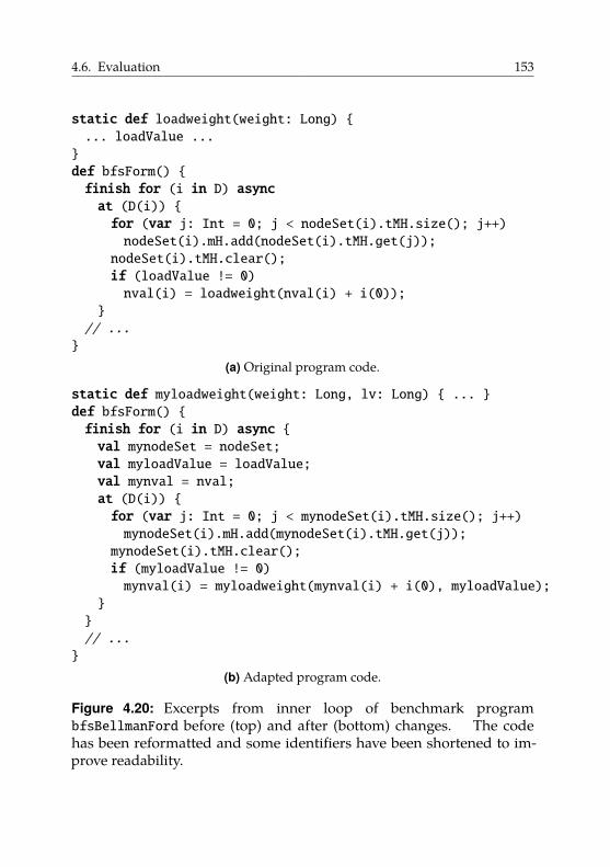
4.6. Evaluation 153
static def loadweight(weight: Long) {... loadValue ...}def bfsForm() {finish for (i in D) asyncat (D(i)) {for (var j: Int = 0; j < nodeSet(i).tMH.size(); j++)nodeSet(i).mH.add(nodeSet(i).tMH.get(j));nodeSet(i).tMH.clear();if (loadValue != 0)nval(i) = loadweight(nval(i) + i(0));
}// ...}
(a) Original program code.
static def myloadweight(weight: Long, lv: Long) { ... }def bfsForm() {finish for (i in D) async {val mynodeSet = nodeSet;val myloadValue = loadValue;val mynval = nval;at (D(i)) {for (var j: Int = 0; j < mynodeSet(i).tMH.size(); j++)mynodeSet(i).mH.add(mynodeSet(i).tMH.get(j));mynodeSet(i).tMH.clear();if (myloadValue != 0)mynval(i) = myloadweight(mynval(i) + i(0), myloadValue);
}}// ...}
(b) Adapted program code.
Figure 4.20: Excerpts from inner loop of benchmark programbfsBellmanFord before (top) and after (bottom) changes. The codehas been reformatted and some identifiers have been shortened to im-prove readability.
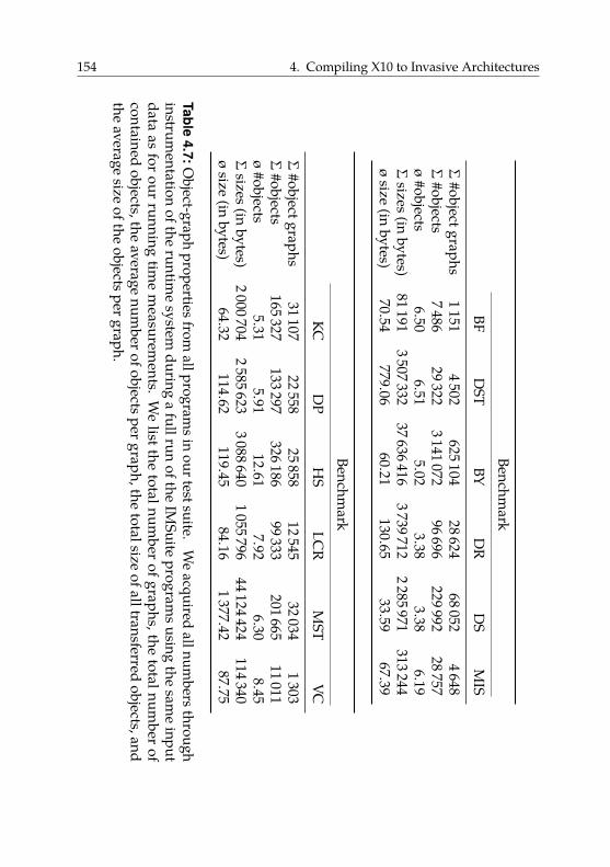
154 4. Compiling X10 to Invasive Architectures
Benchmark
BFD
STBY
DR
DS
MIS
Σ#objectgraphs
11514502
62510428624
680524648
Σ#objects
748629322
314107296696
22999228757
ø#objects
6.506.51
5.023.38
3.386.19
Σsizes(in
bytes)81191
350733237636416
37397122285971
313244ø
size(in
bytes)70.54
779.0660.21
130.6533.59
67.39
Benchmark
KCD
PH
SLC
RM
STVC
Σ#objectgraphs
3110722558
2585812545
320341303
Σ#objects
165327133297
32618699333
20166511011
ø#objects
5.315.91
12.617.92
6.308.45
Σsizes(in
bytes)2000704
25856233088640
105579644124424
114340ø
size(in
bytes)64.32
114.62119.45
84.161377.42
87.75
Table4.7:O
bject-graphpropertiesfrom
allprogramsin
ourtestsuite.W
eacquired
allnumbersthrough
instrumentation
oftheruntim
esystem
duringa
fullrunofthe
IMSuite
programsusing
thesam
einput
dataas
forour
runningtim
em
easurements.
We
listthetotalnum
berofgraphs,the
totalnumber
ofcontained
objects,theaverage
numberofobjectspergraph,the
totalsizeofalltransferred
objects,andthe
averagesize
oftheobjectspergraph.
4.6. Evaluation 155
small object graphs (about 32 bytes on average). Others, such as DST orMST, transfer larger object graphs in the order of 1 KiB on average.
From these numbers, we would suspect DST and MST to have the largestspeedup potential as they transfer the largest object graphs. As anexperiment, we take Tables 4.3 to 4.6 as “lookup tables” for the speedupswe can expect in the best case and use the numbers from Table 4.7 asindices. Regarding indices, the closest match for DST (779 B in 6.51 objects,i.e., about 119 B per object) is n � 23 and E � 27. For MST, the closest matchis n � 23 and E � 210. We retrieve the following best case speedups:
• On Hw-Default relative to Ser-Tlm: 1.39× for DST, and 1.80× forMST;
• On Hw-Default relative to Ser-Off-Opt: 1.31× for DST, and 1.45×for MST;
• On Hw-Delay relative to Ser-Tlm: 0.42× for DST, and 0.63× for MST;• On Hw-Delay relative to Ser-Off-Opt: 0.93× for DST, and 1.05× for
MST.
The upper three rows of Table 4.8 show the running times of all benchmarkson Hw-Default for the three tested variants Ser-Tlm, Ser-Off-Opt, andClone-Off-Opt. First, we see clear differences in the running timesbetween the three variants, which means that due to their distributednature, the benchmarks spend a significant portion of their running timeon communication. This supports our case that efficient data transfers arecrucial for application performance on invasive architectures.
The middle two rows show the speedup of Clone-Off-Opt compared toSer-Tlm and Ser-Off-Opt. On average, Clone-Off-Opt provides a speedupof 1.17× compared to Ser-Tlm. Compared to Ser-Off-Opt, Clone-Off-Optachieves an average speedup of 1.05×. For every test case, Clone-Off-Optis at least as fast as Ser-Tlm or Ser-Off-Opt.
We expected the highest speedups for DST and MST. Our running timemeasurements confirm our supicion. For example, for MST, compared toSer-Off-Opt, the observed speedup of 1.24× is suprisingly close to the best-case speedup of 1.45× we approximated before. In general, speedups aresomewhat lower due to interferences with program behavior unrelated todata transfers. For example, the invalidation of the complete L1 cache may
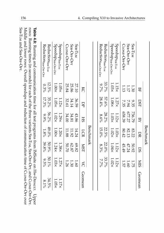
156 4. Compiling X10 to Invasive ArchitecturesBenchm
arkBF
DST
BYD
RD
SM
ISG
eomean
Ser-Tlm1.30
9.35736.79
83.2250.92
1.75Ser-O
ff-Opt
1.177.94
677.2782.13
47.241.60
Clone-O
ff-Opt
1.137.35
658.3980.42
45.491.57
SpeedupSer-Tlm
1.15×1.27×
1.12×1.03×
1.12×1.12×
SpeedupSer-O
ff-Opt
1.03×1.08×
1.03×1.02×
1.04×1.02×
ReductionSer-Tlm
33.7%57.6%
28.2%22.5%
22.0%33.7%
ReductionSer-O
ff-Opt
9.7%28.4%
8.6%15.0%
8.3%7.7%
Benchmark
KCD
PH
SLC
RM
STVC
Geom
eanSer-Tlm
27.1036.59
43.8614.24
69.821.60
Ser-Off-O
pt25.86
34.1434.81
11.9262.87
1.30C
lone-Off-O
pt25.84
32.6134.00
11.8850.70
1.26Speedup
Ser-Tlm1.05×
1.12×1.29×
1.20×1.38×
1.27×1.17×
SpeedupSer-O
ff-Opt
1.00×1.05×
1.02×1.00×
1.24×1.03×
1.05×Reduction
Ser-Tlm12.5%
35.2%56.2%
49.0%50.9%
50.1%34.5%
ReductionSer-O
ff-Opt
0.3%17.3%
9.9%1.8%
39.8%9.5%
8.1%
Table4.8:Running
andcom
munication
time
foralltestprogramsfrom
IMSuite
onH
w-Default.
Upper
rows:Running
times(in
seconds)foreachofthe
threevariantsSer-Tlm,Ser-O
ff-Opt,and
Clone-O
ff-Opt.
Middle
andlow
errows:O
verallspeedupsandreduction
ofcomm
unicationtim
eofC
lone-Off-O
ptoverSer-Tlm
andSer-O
ff-Opt.
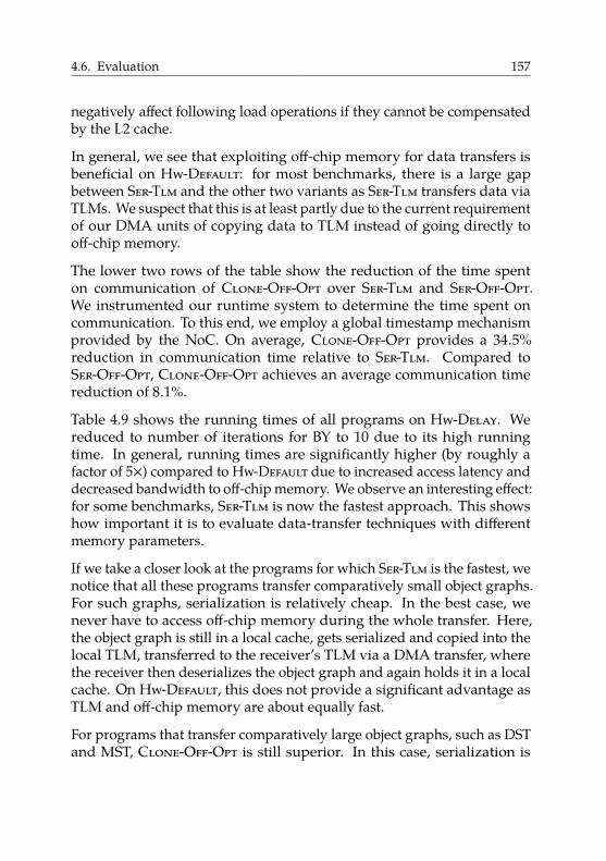
4.6. Evaluation 157
negatively affect following load operations if they cannot be compensatedby the L2 cache.
In general, we see that exploiting off-chip memory for data transfers isbeneficial on Hw-Default: for most benchmarks, there is a large gapbetween Ser-Tlm and the other two variants as Ser-Tlm transfers data viaTLMs. We suspect that this is at least partly due to the current requirementof our DMA units of copying data to TLM instead of going directly tooff-chip memory.
The lower two rows of the table show the reduction of the time spenton communication of Clone-Off-Opt over Ser-Tlm and Ser-Off-Opt.We instrumented our runtime system to determine the time spent oncommunication. To this end, we employ a global timestamp mechanismprovided by the NoC. On average, Clone-Off-Opt provides a 34.5%reduction in communication time relative to Ser-Tlm. Compared toSer-Off-Opt, Clone-Off-Opt achieves an average communication timereduction of 8.1%.
Table 4.9 shows the running times of all programs on Hw-Delay. Wereduced to number of iterations for BY to 10 due to its high runningtime. In general, running times are significantly higher (by roughly afactor of 5×) compared to Hw-Default due to increased access latency anddecreased bandwidth to off-chip memory. We observe an interesting effect:for some benchmarks, Ser-Tlm is now the fastest approach. This showshow important it is to evaluate data-transfer techniques with differentmemory parameters.
If we take a closer look at the programs for which Ser-Tlm is the fastest, wenotice that all these programs transfer comparatively small object graphs.For such graphs, serialization is relatively cheap. In the best case, wenever have to access off-chip memory during the whole transfer. Here,the object graph is still in a local cache, gets serialized and copied into thelocal TLM, transferred to the receiver’s TLM via a DMA transfer, wherethe receiver then deserializes the object graph and again holds it in a localcache. On Hw-Default, this does not provide a significant advantage asTLM and off-chip memory are about equally fast.
For programs that transfer comparatively large object graphs, such as DSTand MST, Clone-Off-Opt is still superior. In this case, serialization is
158 4. Compiling X10 to Invasive Architectures
Benchmark
BFD
STBY
DR
DS
MIS
Geom
eanSer-Tlm
4.2742.14
1995.26128.05
115.8114.95
Ser-Off-O
pt4.36
43.912041.17
132.99121.78
15.21C
lone-Off-O
pt4.33
39.712085.32
128.93121.95
14.98Speedup
Ser-Tlm0.99×
1.06×0.96×
0.99×0.95×
1.00×Speedup
Ser-Off-O
pt1.01×
1.11×0.98×
1.03×1.00×
1.01×
Benchmark
KCD
PH
SLC
RM
STVC
Geom
eanSer-Tlm
104.47120.52
114.6736.70
280.313.93
Ser-Off-O
pt106.88
122.75118.73
37.79286.57
4.01C
lone-Off-O
pt108.01
121.22107.81
36.03233.65
3.85Speedup
Ser-Tlm0.97×
0.99×1.06×
1.02×1.20×
1.02×1.02×
SpeedupSer-O
ff-Opt
0.99×1.01×
1.10×1.05×
1.23×1.04×
1.04×
Table4.9:Running
timesforalltestprogram
sfromIM
Suiteon
Hw-D
elay.U
pperthreerow
s:Runningtim
es(inseconds)foreach
ofthethree
variantsSer-Tlm,Ser-O
ff-Opt,and
Clone-O
ff-Opt.Low
ertwo
rows:O
verallspeedupsofClone-O
ff-Opt
overSer-Tlmand
Ser-Off-O
pt.
4.6. Evaluation 159
so expensive that avoiding it is worth more frequent accesses to off-chipmemory. The speedups of Clone-Off-Opt compared to Ser-Tlm are lowerthan on Hw-Default. This shows that the larger the gap of access speedsbetween off-chip and on-chip memory, the better it is to exploit TLM fortransferring data.
Interestingly, Clone-Off-Opt is faster than Ser-Tlm for DST and MSTalthough our previous considerations suggested otherwise. We suspectthat this is due to Clone-Off-Opt being more cache-friendly. Our syntheticbenchmark program from Section 4.6.4.1 only measured individual datatransfers and did not consider the effect of cache pollution on furtherprogram execution. This effect might be what causes Clone-Off-Opt to befaster in this scenario.
In general, Clone-Off-Opt trades the need to serialize for more frequentoff-chip memory accesses. On Hw-Default, where accessing off-chipmemory is extremely cheap, this trade is always beneficial. As TLM andoff-chip memory are almost equal in terms of latency and bandwidth,Clone-Off-Opt practically avoids some copies without increasing cost.Hence, it is not surprising that Clone-Off-Opt is strictly superior to Ser-Tlm. The situation changes on Hw-Delay. Now, more frequent copies canbe worth avoiding costly accesses to off-chip memory. Then, depending onthe size of the object graphs, Ser-Tlm can be faster than Clone-Off-Opt.
4.6.5. Hardware Overhead
Tradowsky et al. implemented our proposed range operations as anextension to the cache controller of the Gaisler LEON3 processor [Cob17b].Table 4.10 shows that compared to the unmodified cache controller, about15% of additional logic is necessary to implement non-blocking rangeoperations with one range buffer on the Xilinx XUPV5 Virtex-5 FPGA.
Table 4.11 shows the overhead of implementing blocking range operationscompared to the non-blocking variant. The numbers differ from Table 4.10as Tradowsky et al. used a more recent version of our modified cachecontroller. Interestingly, adding range operations in the first place is farmore expensive than making them additionally non-blocking. Making theoperations non-blocking causes a slight increase of the number of slices
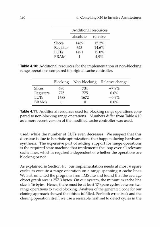
160 4. Compiling X10 to Invasive Architectures
Additional resourcesabsolute relative
Slices 1489 15.2%Register 623 14.6%LUTs 1491 15.0%BRAM 1 4.9%
Table 4.10: Additional resources for the implementation of non-blockingrange operations compared to original cache controller.
Blocking Non-blocking Relative changeSlices 680 734 +7.9%Registers 775 775 0.0%LUTs 1688 1672 −0.9%BRAMs 0 0 0.0%
Table 4.11: Additional resources used for blocking range operations com-pared to non-blocking range operations. Numbers differ from Table 4.10as a more recent version of the modified cache controller was used.
used, while the number of LUTs even decreases. We suspect that thisdecrease is due to heuristic optimizations that happen during hardwaresynthesis. The expensive part of adding support for range operationsis the required state machine that implements the loop over all relevantcache lines, which is required independent of whether the operations areblocking or not.
As explained in Section 4.5, our implementation needs at most n sparecycles to execute a range operation on a range spanning n cache lines.We instrumented the programs from IMSuite and found that the averageobject graph size is 257.3 bytes. On our system, the minimum cache linesize is 16 bytes. Hence, there must be at least 17 spare cycles between tworange operations to avoid blocking. Analysis of the generated code for ourcloning approach showed that this is fulfilled. For both write-back and thecloning operation itself, we use a resizable hash set to detect cycles in the
4.6. Evaluation 161
object graph. Operating on the hash set involves enough arithmetic andcontrol flow instructions to hide the range operation’s latency. Therefore,executing a range operation during Clone-Off-Opt takes one cycle fromthe view of the processor for the average object graph.
So, is it worth the effort? Let us take the L2 cache of our prototype systemas a concrete example. This cache offers means to invalidate a singlecache line, identified by an address, but does not have the extensions thatwe proposed in Section 4.5. Hence, to invalidate an address range, theprocessor has to execute a software loop and issue one invalidation perrelevant cache line. The loop boils down to an addition, a store (whichtriggers the invalidation via a memory-mapped register), a comparison,and a conditional branch. Additionally, the cache takes five clock cycles toprocess each invalidation [Cob16, section 74.3.3]. Hence, each invalidationtakes roughly 10 cycles.
With an average object graph size of 17 cache lines, our loop takesin the order of 200 clock cycles, which we can reduce to 1 (from theview of the processor) in the best case using the non-blocking rangeoperation extension. This sound like an impressive speedup. However,compared to the latency of the memory accesses following the invalidation,this difference is negligible, as fetching a single cache line can easilytake hundreds of cycles, depending on the structure of the memorysubsystem.
Hence, we conclude that while adding range operations is feasible, itis not worth the additional hardware cost. The literature that requestssuch instructions (cf. Section 4.5) probably did not consider this cost. Weagree that more fine-grained cache control is crucial for performance onnon-cache-coherent architectures to support software-managed coherence.However, means to invalidate or write back individual cache lines aresufficient and cheap to implement. All remaining functionality shouldbe implemented in software. However, our findings may be useful in theimplementation of remote invalidation operations, which we discuss inAppendix A.1.
162 4. Compiling X10 to Invasive Architectures
4.6.6. Threats to Validity
In this section, we try to list all limitations of our experiments as well asdecisions that may have influenced our results.
The most important limitation of our prototype is that the differenceconcerning latency and bandwidth of TLMs compared to off-chip memoryis far less pronounced than on real systems. We tried to alleviate thislimitation by using a hardware variant with artificially increased DRAMlatency. However, this does not capture all differences between ourprototype and a real chip. Hence, behavior on a real ASIC with realisticclock frequencies and latencies may be significantly different.
Our prototype architecture is compute-bound. Our cores only run at25 MHz, while our SRAM and DRAM are disproportionately faster. Thisis not realistic, as on a real chip this relationship would be reversed: thememory would be much slower than the cores. While this effect is notas pronounced on Hw-Delay as on Hw-Default, it may still have led usto overstate the cost of serialization. On a real chip it may thus not beworthwhile to use cloning instead of a serialization-based approach or itmay only be worthwhile for object graphs of a certain minimum size, aswe observed on Hw-Delay. On Hw-Default, such a break-even point isnot measurable: our numbers show that cloning is always at least as fastas serialization-based approaches.
We did not reproduce the state of the art for message passing techniquesusing on-chip memories. Almost all existing work has been done inthe context of the Intel SCC. As our hardware is sufficiently different,we could not reuse that work directly. Due to time constraints, wedid not port existing projects to our hardware platform. Additionally,differences between on-chip and off-chip memory are hard to emulate onan FPGA (see above), thus porting these approaches is also problematicconceptually. Hence, it is possible that our numbers acquired for Ser-Tlmare not representative and thus must be interpreted carefully.
Our TLMs are too large compared to other system parameters. A sizeof 8 MiB per tile is unrealistic, e.g., the Intel SCC has 16 KiB of on-chipmemory per tile, which contains two cores. This does not affect thecomparison of Ser-Off-Opt with Clone-Off-Opt, as they do not use TLMs
4.6. Evaluation 163
to transfer data. It gives Ser-Tlm an unfair advantage, as it does not needto split messages because every message fits completely into the TLM.
We did not integrate our hardware extension into the platform on whichwe performed our benchmarks. Hence, we did not have fine-grainedcontrol over the L1 cache; we could only flush it completely. This affectsboth Ser-Off-Opt and Clone-Off-Opt. Hence, their absolute runningtimes are skewed; however, the relative comparison of the two approachesis fair.
Our proposed pull-style cloning approach is not one-sided as the receiveractively partakes in the data transfer. In contrast, serialization-basedapproaches are easy to implement in a one-sided fashion. In conjunctionwith possibly lower costs for serialization (see above) this could lead toserialization-based approaches being superior to cloning. For example,assume that our architecture was memory-bound, had larger caches, andour DMA units supported transfer to off-chip memory. Then, it is possiblethat serializing an object graph and then copying it using a DMA transferwould be more efficient.
We use only one I/O tile with external memory, hence our system does nothave distributed off-chip memory. Additionally, our synthesized chip isquite small and every tile has a low maximum distance to off-chip memoryof two hops.
Our cores have write-through L1 caches, which avoids some difficultproblems. Suppose we had write-back L1 caches and core 1 wanted towrite back a block of memory B. It is now possible that part of B isheld in the L1 cache of a different core, say core 2. Hence, we eithersynchronize all cores and force the software to execute the necessarywriteback operation on all cores of a tile. Or, we add hardware supportfor writing back or invalidating cache lines in caches other than the one ofthe current core. This could, for example, be realized by letting all cachecontrollers snoop such operations and execute them on their respectivecaches; see Appendix A.1 for details.
We do not support custom serialization formats in our cloning approach.X10 allows types to implement the interfacex10.io.CustomSerialization.This signifies that these types do not use the default serialization methodsgenerated by the compiler but specify their own custom serialization
164 4. Compiling X10 to Invasive Architectures
format. Supporting custom serializable types in the cloning approach iscumbersome. Our cloning approach hinges on the fact that all accesses toforeign memory partitions happen under control of the compiler. Hence,the necessary write-backs and invalidations can be inserted automati-cally. If we look at custom serialization formats, its counterpart in thecloning approach would be a user-implemented clone function. Hence,user-controlled code would need to access objects from foreign memorypartitions, which requires a write-back on the sending side and a preced-ing invalidation on the receiving side. We see no other possibility thanletting the user issue these cache operations, which is error-prone.
We did not consider cache architectures with more than two levels. Ifwe assume a cache hierarchy consisting of L1, L2, and L3 cache, whichis common on current processors, invalidations and write-backs must beeffective on all cache levels. This can influence the cost and complexity ofthe necessary hardware support.
We do not evaluate the power impact of our proposed cache extension. Ourextension causes the cache to become active during more cycles; specificallyduring spare cycles. This causes an increased power usage, which couldmake our extension unattractive. However, if an address range must beinvalidated or written back, some component has to do this work. Ifthe hardware does not support it directly, a general-purpose processormust take over, which probably requires significantly more power. Hence,depending on the frequency of range operations, a hardware-acceleratedimplementation could even lower power usage.
4.7. Relation to Invasive X10
So far, we have run standard X10 programs on our platform. However,as explained in Section 3.1, Invasive Computing also proposes a newprogramming paradigm. In the following, we first explain how weintegrated this paradigm into X10. We call the resulting extended languageInvasive X10 [Bra+14] to differentiate it from regular X10. Subsequently,we argue that our work on data transfers from the previous sections isespecially important in the context of Invasive X10.
4.7. Relation to Invasive X10 165
Invasive X10. The invasive paradigm focuses on exclusive resourceallocation. Resources are partitioned into claims. Invasive applicationscan create (“invade”), resize (“reinvade”), use (“infect”), and destroy(“retreat”) claims.
When trying to integrate the idea of claims with existing X10 languagesemantics, one quickly notices the following problem. Suppose we runan invasive X10 application on an invasive architecture with four tiles.Assume that, initially, the application only has one claim containing coreson tile 0. How many X10 places does this application see if it queries, e.g.,the number of places?
One possibility would be that it sees four places (as we represent eachtile by one place). In regular X10, the number of places is fixed during aprogram run [Sar+16, section 13]. If we want to keep this rule, the answerto our question from before must be four; otherwise, we would never beable to use more than one tile. Hence, all places would be visible, but onlysome places should be usable for the application. Thus, if an applicationuses places not currently contained in its claim, we would need to reportsome kind of error, e.g., by throwing an exception. We could then providemeans to query whether a place is contained in a given claim to enablethe programmer to prevent these errors.
This basically adds the notion of “allowed” and “disallowed” places toX10. As existing X10 code does not know about this distinction, it has tobe adapted. For example, all existing X10 standard library code that dealswith multiple places must be changed. Thus, we conclude that this designis feasible in theory, but inelegant and impractical.
Instead, we propose to lift the concept of claims to a level above theconcept of places. Now, regular X10 lives inside a claim: an X10 applicationonly sees multiple places if the claim it currently runs in contains coresfrom multiple tiles. In general, the application’s view is restricted to theresources that are contained in its claim. Hence, in this design the answerto our question from before is one.
This design breaks X10’s rule that the number of places is fixed. Supposea program changes its claim. It may acquire additional cores on a differenttile, which we must, according to our new design, make available as a
166 4. Compiling X10 to Invasive Architectures
new place. Hence, the number of places may increase. Conversely, theapplication may free resources so that the number of places decreases.
In general, the number of places is now dynamic, and we call the re-sulting extended X10 language Invasive X10. Invasive X10 requireschanges to the runtime system. For example, we have to convert the staticfield Place.NUM_PLACES to a method Place.numPlaces(); for detailssee [Bra+14].
The programmer deals with claims analogously to places. Hence, eachclaim is represented as a regular X10 object of type Claim, just likeeach place is an object of type Place. The class Claim offers a staticmethod invade() to create new claims, and non-static methods infect(),reinvade(), and retreat() to operate on existing claims. Just likeat allows changing between places, infect allows changing betweenclaims.
From the viewpoint of an application running inside a claim, the regularX10 semantics hold. Therefore, regular X10 can be embedded naturallyinto Invasive X10: a regular X10 program behaves exactly like an InvasiveX10 program that runs inside a claim containing all resources in thesystem. In fact, this is exactly how we performed all our experiments inSection 4.6. Here, we configured our X10 runtime system to create a singleclaim containing all system resources during initialization and destroyedit on program exit, never modifying it in the meantime. Hence, we couldrun regular unmodified X10 programs.
Data redistribution. If the number of places changes, the program hasto adapt. As such resource changes only happen at well-defined programpoints, such as calls to reinvade(), the programmer does not have to dealwith asynchronous events36. For details on how to handle appearing anddisappearing places, see [Bra+14] and [Cun+14]. In the following, wefocus on one aspect: data redistribution.
Suppose an invasive application has acquired additional cores and itsclaim has grown from cores on one tile to cores on three tiles. In orderto exploit the processing power of the cores on the two new tiles, they
36Except for the special class of malleable applications, see [BMZ15] for details.
4.7. Relation to Invasive X10 167
must be fed enough data. Hence, the application must redistribute itsdata from one place to three places.
As we have discussed before, the primary means for data transfers betweenplaces in X10 are Array.asyncCopy() and at for simple and complex datastructures, respectively. We can accelerate both means to transfer datausing the techniques we presented in Sections 4.3 and 4.4.
The invasive paradigm requires resource-aware applications that fre-quently adapt their resource needs. Otherwise, the system has little roomto optimize resource usage for efficiency or predictability. In general,frequent resource changes induce frequent data transfers to redistributedata.
To support our argument, we perform the following experiment. We usean existing X10 application that exists in an invasive and a non-invasivevariant. We use the multigrid [Bun+13] application37. This applicationstems from the high performance computing domain and is a numericsimulation of heat distribution on a metal plate. We instrumented the X10runtime library to measure the amount of data transferred. We then ranthe invasive and the non-invasive variant of the application with the sameparameters38 and determined the amount of data transferred.
We did not perform our experiments on the hardware prototype. Instead,we generated x86 code and used the x86guest variant of OctoPOS39 , whichruns as a guest operating system under Linux. The OctoPOS interfaceto applications and compiler is exactly the same as on the hardwareprototype. As the sizes of all X10 data types are fixed and pointers have32 bits on both x86 and SPARC, the number of transferred bytes is thesame as on the hardware prototype. Using the x86 variant of OctoPOSallowed us to simulate three different invasive hardware configurations: areplica of the prototype with 4 tiles with 4 cores each; a variant with 6 tileshaving 4 cores each; and a variant with 8 tiles having 6 cores each.
37We use x10i Git revision 31183335a89917f489046da746c5181174a7bdb3 and the multi-grid application of Git revision 6bb6ef6ff5c260eb0391bd12b82f052184c3a097.
38We set the number of simulated timesteps to 50 and used the defaults for all otherparameters.
39We used Git revision a0a23ef38fe2b6d7b9c9544a94c990cb2201ad57.
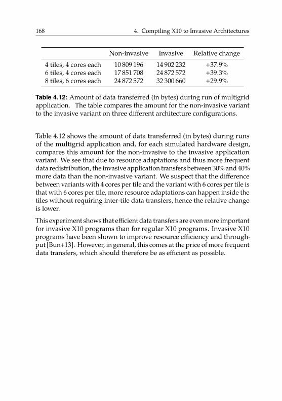
168 4. Compiling X10 to Invasive Architectures
Non-invasive Invasive Relative change4 tiles, 4 cores each 10 809 196 14 902 232 +37.9%6 tiles, 4 cores each 17 851 708 24 872 572 +39.3%8 tiles, 6 cores each 24 872 572 32 300 660 +29.9%
Table 4.12: Amount of data transferred (in bytes) during run of multigridapplication. The table compares the amount for the non-invasive variantto the invasive variant on three different architecture configurations.
Table 4.12 shows the amount of data transferred (in bytes) during runsof the multigrid application and, for each simulated hardware design,compares this amount for the non-invasive to the invasive applicationvariant. We see that due to resource adaptations and thus more frequentdata redistribution, the invasive application transfers between 30% and 40%more data than the non-invasive variant. We suspect that the differencebetween variants with 4 cores per tile and the variant with 6 cores per tile isthat with 6 cores per tile, more resource adaptations can happen inside thetiles without requiring inter-tile data transfers, hence the relative changeis lower.
This experiment shows that efficient data transfers are even more importantfor invasive X10 programs than for regular X10 programs. Invasive X10programs have been shown to improve resource efficiency and through-put [Bun+13]. However, in general, this comes at the price of more frequentdata transfers, which should therefore be as efficient as possible.
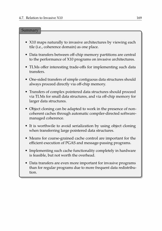
4.7. Relation to Invasive X10 169
Summary
• X10 maps naturally to invasive architectures by viewing eachtile (i.e., coherence domain) as one place.
• Data transfers between off-chip memory partitions are centralto the performance of X10 programs on invasive architectures.
• TLMs offer interesting trade-offs for implementing such datatransfers.
• One-sided transfers of simple contiguous data structures shouldalways proceed directly via off-chip memory.
• Transfers of complex pointered data structures should proceedvia TLMs for small data structures, and via off-chip memory forlarger data structures.
• Object cloning can be adapted to work in the presence of non-coherent caches through automatic compiler-directed software-managed coherence.
• It is worthwile to avoid serialization by using object cloningwhen transferring large pointered data structures.
• Means for coarse-grained cache control are important for theefficient execution of PGAS and message-passing programs.
• Implementing such cache functionality completely in hardwareis feasible, but not worth the overhead.
• Data transfers are even more important for invasive programsthan for regular programs due to more frequent data redistribu-tion.

Values: 1 2 3 4 5Values: 2 3 4 5 1Values: 3 4 5 1 2Values: 4 5 1 2 4
Output of a test program on anearly hardware prototype
5Code Generation with Permutation Instructions
In this chapter, we investigate the use of permutation instructions tospeed up the execution of shuffle code. We first present an instructionset extension and describe a possible hardware implementation. We thenstudy different code-generation approaches and evaluate benefits andoverheads. Parts of this chapter have been published in [Moh+13] and[BMR15b; BMR15a].
Motivation. During compilation of a program, register allocation isthe task of mapping program variables to machine registers. Duringregister allocation, the compiler often emits shuffle code, consisting of copyand swap operations, that transfers data between the registers. Threecommon sources of shuffle code are (i) conflicting register mappings atjoins in the control flow of the program, e.g., due to if-statements orloops; (ii) the calling convention for procedures, which often dictatesthat input arguments or results must be placed in certain registers; and(iii) constrained machine instructions that only allow a subset of registersto occur as operands.
Figure 5.1 shows an example situation where the compiler needs to emitshuffle code. In Figure 5.1a, we assume that the compiler has mapped
171
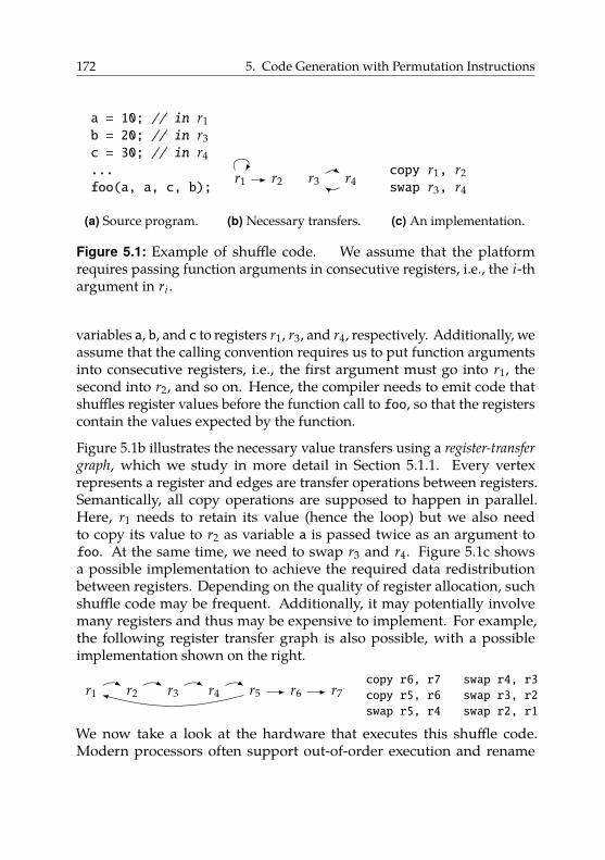
172 5. Code Generation with Permutation Instructions
a = 10; // in r1b = 20; // in r3c = 30; // in r4...foo(a, a, c, b);
(a) Source program.
r1 r2 r3 r4
(b) Necessary transfers.
copy r1, r2swap r3, r4
(c) An implementation.
Figure 5.1: Example of shuffle code. We assume that the platformrequires passing function arguments in consecutive registers, i.e., the i-thargument in ri .
variables a, b, and c to registers r1, r3, and r4, respectively. Additionally, weassume that the calling convention requires us to put function argumentsinto consecutive registers, i.e., the first argument must go into r1, thesecond into r2, and so on. Hence, the compiler needs to emit code thatshuffles register values before the function call to foo, so that the registerscontain the values expected by the function.
Figure 5.1b illustrates the necessary value transfers using a register-transfer
graph, which we study in more detail in Section 5.1.1. Every vertexrepresents a register and edges are transfer operations between registers.Semantically, all copy operations are supposed to happen in parallel.Here, r1 needs to retain its value (hence the loop) but we also needto copy its value to r2 as variable a is passed twice as an argument tofoo. At the same time, we need to swap r3 and r4. Figure 5.1c showsa possible implementation to achieve the required data redistributionbetween registers. Depending on the quality of register allocation, suchshuffle code may be frequent. Additionally, it may potentially involvemany registers and thus may be expensive to implement. For example,the following register transfer graph is also possible, with a possibleimplementation shown on the right.
r1 r2 r3 r4 r5 r6 r7copy r6, r7copy r5, r6swap r5, r4
swap r4, r3swap r3, r2swap r2, r1
We now take a look at the hardware that executes this shuffle code.Modern processors often support out-of-order execution and rename
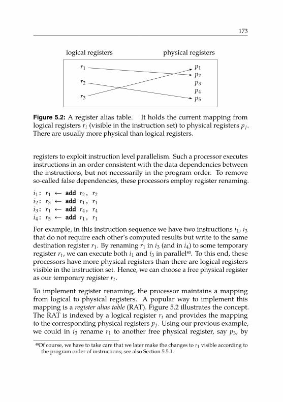
173
logical registers physical registers
r1
r2
r3
p1p2p3p4p5
Figure 5.2: A register alias table. It holds the current mapping fromlogical registers ri (visible in the instruction set) to physical registers p j .There are usually more physical than logical registers.
registers to exploit instruction level parallelism. Such a processor executesinstructions in an order consistent with the data dependencies betweenthe instructions, but not necessarily in the program order. To removeso-called false dependencies, these processors employ register renaming.
i1: r1 ← add r2, r2i2: r3 ← add r1, r1i3: r1 ← add r4, r4i4: r5 ← add r1, r1
For example, in this instruction sequence we have two instructions i1, i3that do not require each other’s computed results but write to the samedestination register r1. By renaming r1 in i3 (and in i4) to some temporaryregister rt , we can execute both i1 and i3 in parallel40. To this end, theseprocessors have more physical registers than there are logical registersvisible in the instruction set. Hence, we can choose a free physical registeras our temporary register rt .
To implement register renaming, the processor maintains a mappingfrom logical to physical registers. A popular way to implement thismapping is a register alias table (RAT). Figure 5.2 illustrates the concept.The RAT is indexed by a logical register ri and provides the mappingto the corresponding physical registers p j . Using our previous example,we could in i3 rename r1 to another free physical register, say p3, by
40Of course, we have to take care that we later make the changes to r1 visible according tothe program order of instructions; see also Section 5.5.1.
174 5. Code Generation with Permutation Instructions
adapting the RAT accordingly. Subsequent instructions all access theirinput registers via the RAT. Hence, instruction i4 would read its inputsfrom p3.
We can also use register-renaming techniques to efficiently rearrangeregister contents. For example, by exchanging the targets of two entries inthe RAT, we can effectively swap the register contents. Note that we do notphysically move the register contents; all we do is modify an indirectiontable that reroutes subsequent register uses. As a table entry is usually justa register index, it is fairly small and can therefore be modified efficiently.In contrast, typical sizes of actual register contents are 32 or 64 bits, hencethey are more costly to modify. In principle, there is no limit on thenumber of RAT entries that we modify at the same time, hence we canalso imagine performing operations involving more than two registers.
We now observe the following: on the hardware side, we have register-renaming units providing the ability to efficiently rearrange registercontents for multiple registers at once. On the software side, we havethe compiler needing exactly this functionality to implement shuffle code.Currently, however, the compiler cannot directly use this hardware. Theregister renaming is purely controlled by hardware and is transparentto software. Hence, the compiler has to use what usual instruction setsprovide: copy instructions and, if available, exchange instructions on tworegisters. This results in potentially long sequences of copy and swapinstructions.
At this point, we pose the following questions:
1. How can we eliminate the detour induced by the instruction setand give the compiler direct access to the underlying hardware’sregister-renaming capabilities?
2. How can the compiler leverage the new functionality to implementshuffle code more efficiently?
3. Is it worthwhile?
Contribution. In this chapter, we investigate these questions. We proposenovel permutation instructions that allow to permute the contents of smallsets of registers, develop code-generation approaches that exploit the new
175
instructions to implement shuffle code more concisely, and evaluate whenusing the new instructions is advantageous. We base our presentationon an in-order architecture extended with renaming capabilities similarto the RAT mentioned before. We later discuss how our findings maycarry over to an out-of-order architecture already incorporating registerrenaming.
Structure. The structure of the following chapters is as follows:
• In Section 5.1, we give an introduction to the problem setting. Wecover relevant work related to register allocation and explain theorigin of shuffle code. This motivates our concept of permutationinstructions that permute up to five registers, which we introducein the following. We describe how to extend an existing RISC ISAwith the new instructions.
• In Section 5.2, as an instruction set extension must always undergoa feasibility study, we describe a prototype implementation of thepermutation-instruction concept in an existing RISC microarchitec-ture.
• In Section 5.3, we study code-generation approaches for the imple-mentation of shuffle code exploiting the new instructions. After firstformalizing the problem statement, we propose two algorithms: afast heuristic and a dynamic-programming-based technique. We for-mally prove the optimality of the dynamic-programming approach,i.e., we show that its solutions always have minimal length.
• In Section 5.4, we implement both code-generation approaches ina compiler and extensively evaluate compile times as well as codequality using a comprehensive testsuite. We collect precise dynamicinstruction counts and validate these numbers by measuring actualrunning times on an FPGA-based prototype implementation of thepermutation hardware.
• In Section 5.5, we argue that the proposed permutation instructionsshould be cheap to implement on current out-of-order processors thatalready support register renaming. We describe register-renaminghardware techniques in more detail and discuss how our permuta-tion instructions fit into this scenario.
176 5. Code Generation with Permutation Instructions
Acknowledgments. This part of this dissertation is joint work withLars Bauer, Sebastian Buchwald, Artjom Grudnitsky, Sebastian Hack,Jörg Henkel, Tobias Modschiedler, and Ignaz Rutter [Moh+13; BMR15b;BMR15a]. The complete microarchitecture extension we describe inSection 5.2 as well as the FPGA-based prototype we use in Section 5.4were designed and implemented by Lars Bauer, Artjom Grudnitsky,Tobias Modschiedler, and Jörg Henkel [Mod13; Moh+13]. The hardwareextensions described in Section 5.2 as well as their overhead analysis inSection 5.4.6 are thus not a contribution of this dissertation.
The formal foundations of the code-generation problem and the optimalcode-generation algorithm are joint work with Sebastian Buchwald andIgnaz Rutter [BMR15b; BMR15a]. Concerning the theoretical groundworkin Section 5.3, it is difficult to determine exactly who contributed what. Theauthor did contribute significantly to the proofs and proof structure for thegreedy algorithm (Section 5.3.3). The optimal dynamic program and itsproofs (Section 5.3.5) are almost exclusively Rutter’s work. In both cases,the formal rigor with which we present the material is exclusively Rutter’scontribution. We thus do not consider Section 5.3.5 a contribution of thisdissertation. However, as the author was closely involved, throughout allsections we use “we” instead of “Rutter” and “they”.
5.1. Introduction
In this section, we give a brief explanation of the origin of shuffle code inthe context of SSA-based register allocation. Then, we present our conceptof permutation instructions to permute register contents. We do not buildour presentation from first principles. Instead, we restrict ourselves tobriefly introducing the most important terms and refer to appropriateliterature where needed.
5.1.1. Parallel Copies and Register Transfer Graphs
Static Single Assignment Form (SSA form) [ASU86, section 6.2.4] hasbecome a key property of modern compiler intermediate representations.
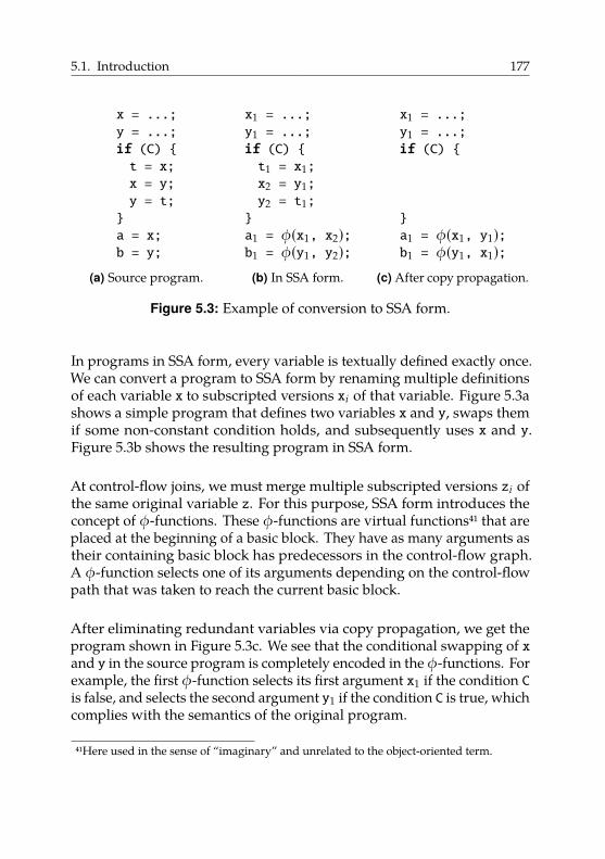
5.1. Introduction 177
x = ...;y = ...;if (C) {t = x;x = y;y = t;}a = x;b = y;
(a) Source program.
x1 = ...;y1 = ...;if (C) {t1 = x1;x2 = y1;y2 = t1;}a1 = φ(x1, x2);b1 = φ(y1, y2);
(b) In SSA form.
x1 = ...;y1 = ...;if (C) {
}a1 = φ(x1, y1);b1 = φ(y1, x1);
(c) After copy propagation.
Figure 5.3: Example of conversion to SSA form.
In programs in SSA form, every variable is textually defined exactly once.We can convert a program to SSA form by renaming multiple definitionsof each variable x to subscripted versions xi of that variable. Figure 5.3ashows a simple program that defines two variables x and y, swaps themif some non-constant condition holds, and subsequently uses x and y.Figure 5.3b shows the resulting program in SSA form.
At control-flow joins, we must merge multiple subscripted versions zi ofthe same original variable z. For this purpose, SSA form introduces theconcept of φ-functions. These φ-functions are virtual functions41 that areplaced at the beginning of a basic block. They have as many arguments astheir containing basic block has predecessors in the control-flow graph.A φ-function selects one of its arguments depending on the control-flowpath that was taken to reach the current basic block.
After eliminating redundant variables via copy propagation, we get theprogram shown in Figure 5.3c. We see that the conditional swapping of xand y in the source program is completely encoded in the φ-functions. Forexample, the first φ-function selects its first argument x1 if the condition Cis false, and selects the second argument y1 if the condition C is true, whichcomplies with the semantics of the original program.
41Here used in the sense of “imaginary” and unrelated to the object-oriented term.
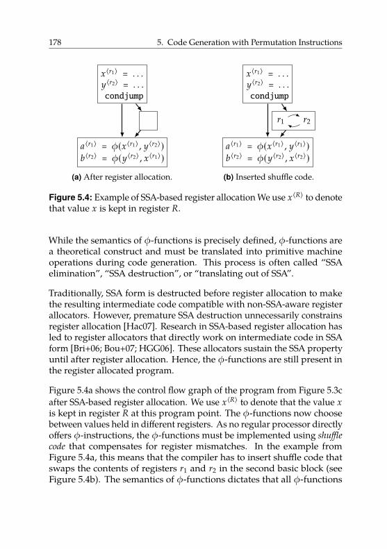
178 5. Code Generation with Permutation Instructions
x〈r1〉 = . . .y〈r2〉 = . . .condjump
a〈r1〉 = φ(x〈r1〉 , y〈r2〉)b〈r2〉 = φ(y〈r2〉 , x〈r1〉)
(a) After register allocation.
x〈r1〉 = . . .y〈r2〉 = . . .condjump
a〈r1〉 = φ(x〈r1〉 , y〈r1〉)b〈r2〉 = φ(y〈r2〉 , x〈r2〉)
r1 r2
(b) Inserted shuffle code.
Figure 5.4: Example of SSA-based register allocation We use x〈R〉 to denotethat value x is kept in register R.
While the semantics of φ-functions is precisely defined, φ-functions area theoretical construct and must be translated into primitive machineoperations during code generation. This process is often called “SSAelimination”, “SSA destruction”, or “translating out of SSA”.
Traditionally, SSA form is destructed before register allocation to makethe resulting intermediate code compatible with non-SSA-aware registerallocators. However, premature SSA destruction unnecessarily constrainsregister allocation [Hac07]. Research in SSA-based register allocation hasled to register allocators that directly work on intermediate code in SSAform [Bri+06; Bou+07; HGG06]. These allocators sustain the SSA propertyuntil after register allocation. Hence, the φ-functions are still present inthe register allocated program.
Figure 5.4a shows the control flow graph of the program from Figure 5.3cafter SSA-based register allocation. We use x〈R〉 to denote that the value xis kept in register R at this program point. The φ-functions now choosebetween values held in different registers. As no regular processor directlyoffers φ-instructions, the φ-functions must be implemented using shuffle
code that compensates for register mismatches. In the example fromFigure 5.4a, this means that the compiler has to insert shuffle code thatswaps the contents of registers r1 and r2 in the second basic block (seeFigure 5.4b). The semantics of φ-functions dictates that all φ-functions
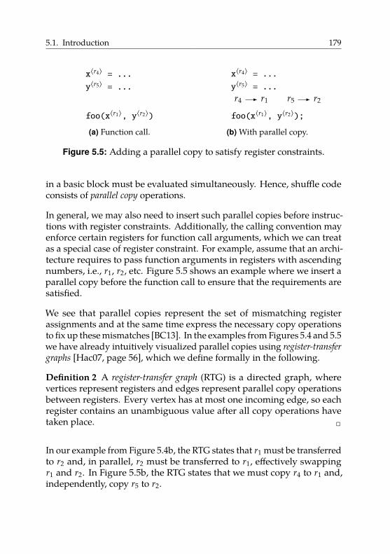
5.1. Introduction 179
x〈r4〉 = ...
y〈r5〉 = ...
foo(x〈r1〉, y〈r2〉)
(a) Function call.
x〈r4〉 = ...
y〈r5〉 = ...r4 r1 r5 r2
foo(x〈r1〉, y〈r2〉);
(b) With parallel copy.
Figure 5.5: Adding a parallel copy to satisfy register constraints.
in a basic block must be evaluated simultaneously. Hence, shuffle codeconsists of parallel copy operations.
In general, we may also need to insert such parallel copies before instruc-tions with register constraints. Additionally, the calling convention mayenforce certain registers for function call arguments, which we can treatas a special case of register constraint. For example, assume that an archi-tecture requires to pass function arguments in registers with ascendingnumbers, i.e., r1, r2, etc. Figure 5.5 shows an example where we insert aparallel copy before the function call to ensure that the requirements aresatisfied.
We see that parallel copies represent the set of mismatching registerassignments and at the same time express the necessary copy operationsto fix up these mismatches [BC13]. In the examples from Figures 5.4 and 5.5we have already intuitively visualized parallel copies using register-transfer
graphs [Hac07, page 56], which we define formally in the following.
Definition 2 A register-transfer graph (RTG) is a directed graph, wherevertices represent registers and edges represent parallel copy operationsbetween registers. Every vertex has at most one incoming edge, so eachregister contains an unambiguous value after all copy operations havetaken place. 2
In our example from Figure 5.4b, the RTG states that r1 must be transferredto r2 and, in parallel, r2 must be transferred to r1, effectively swappingr1 and r2. In Figure 5.5b, the RTG states that we must copy r4 to r1 and,independently, copy r5 to r2.
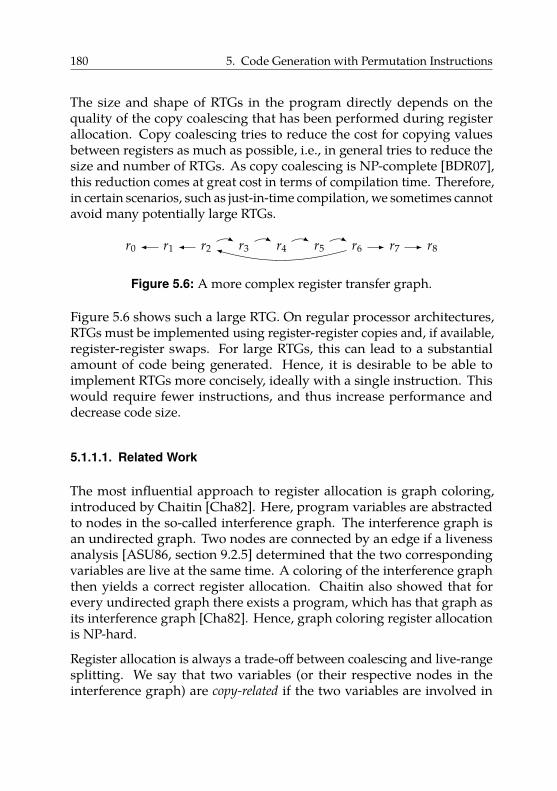
180 5. Code Generation with Permutation Instructions
The size and shape of RTGs in the program directly depends on thequality of the copy coalescing that has been performed during registerallocation. Copy coalescing tries to reduce the cost for copying valuesbetween registers as much as possible, i.e., in general tries to reduce thesize and number of RTGs. As copy coalescing is NP-complete [BDR07],this reduction comes at great cost in terms of compilation time. Therefore,in certain scenarios, such as just-in-time compilation, we sometimes cannotavoid many potentially large RTGs.
r0 r1 r2 r3 r4 r5 r6 r7 r8
Figure 5.6: A more complex register transfer graph.
Figure 5.6 shows such a large RTG. On regular processor architectures,RTGs must be implemented using register-register copies and, if available,register-register swaps. For large RTGs, this can lead to a substantialamount of code being generated. Hence, it is desirable to be able toimplement RTGs more concisely, ideally with a single instruction. Thiswould require fewer instructions, and thus increase performance anddecrease code size.
5.1.1.1. Related Work
The most influential approach to register allocation is graph coloring,introduced by Chaitin [Cha82]. Here, program variables are abstractedto nodes in the so-called interference graph. The interference graph isan undirected graph. Two nodes are connected by an edge if a livenessanalysis [ASU86, section 9.2.5] determined that the two correspondingvariables are live at the same time. A coloring of the interference graphthen yields a correct register allocation. Chaitin also showed that forevery undirected graph there exists a program, which has that graph asits interference graph [Cha82]. Hence, graph coloring register allocationis NP-hard.
Register allocation is always a trade-off between coalescing and live-rangesplitting. We say that two variables (or their respective nodes in theinterference graph) are copy-related if the two variables are involved in
5.1. Introduction 181
a copy instruction. Coalescing aims to assign the same register to twocopy-related variables, thereby eliminating the copy altogether. In theinterference graph, this corresponds to merging two copy-related nodes.In general, coalescing decreases the number of copies but may increasethe register pressure and therefore may cause additional spill code. Spillcode saves registers to memory (usually in the current stack frame) andlater reloads the spilled value to a register, which is potentially costly.
On the other hand, splitting the live range of a variable means creating anew definition of this variable and inserting a copy instruction betweenthe old definition and the new definition. In the interference graph,this corresponds to splitting a single node into two distinct nodes. Thecopy instruction gives the register allocator additional freedom as thevariable can now effectively change its register after the copy instruction(as represented by the two unconnected nodes in the interference graph).However, this flexibility is not for free: too many copy instructions canslow down execution significantly. In general, live-range splitting mayreduce the number of spills, but may increase the number of copies.
Chaitin’s original approach always merges two copy-related nodes in theinterference graph. This can increase the register pressure of the programand, in turn, can lead to additional spill code. Therefore, this coalescingapproach is called aggressive coalescing.
Since Chaitin’s fundamental work, various improved coalescing techniqueshave been proposed. Briggs et al. [BCT94] derived criteria for conservative
coalescing, which means that coalescing never trades a copy for a spill. Parkand Moon [PM04] proposed optimistic coalescing, which is a conservativetechnique that tries to undo aggressive coalescing in case a spill wasintroduced because of a coalesced copy. In general, as the gap betweenprocessor speed and memory speed steadily increased, splitting liveranges more often and thereby trading spills for more copies became moreattractive.
In 2006, different articles independently proposed performing registerallocation on programs in SSA form [Bri+06; Bou+07; HGG06]. In contrastto traditional graph-coloring allocation, the φ-functions are still presentafter register allocation [HGG06]. For programs in SSA form, the containedφ-functions provide implicit live-range splits. The interference graph of a
182 5. Code Generation with Permutation Instructions
program in SSA form is chordal. This means it is optimally colorable inpolynomial time.
In SSA-based register allocation, it is up to the register assignment or alater coalescing pass to find an assignment that involves as few copiesas possible. This problem is again NP-hard even on SSA-form pro-grams [BDR07; Hac07]. Various coalescing techniques for SSA-basedregister allocation have been proposed. Pereira et al. [PP05] and Bouchezet al. [BDR08] proposed novel conservative criteria for node coalescing.Hack and Goos [HG08] introduced recoloring to improve a previouslyfound coloring by trying to assign two copy-related nodes the same color.Grund and Hack [GH07] presented an efficient ILP-based algorithm.
Braun et al. [BMH10] and Colombet et al. [Col+11] presented biasing tech-niques for the register-assignment phase. Usually, the allocator choosesone register out of a list of free registers. By biasing this choice, those allo-cators try to pick the same registers for copy-related variables in the firstplace instead of relying on a post pass, such as recoloring. Biasing usuallyproduces colorings of inferior quality compared to more heavyweighttechniques like recoloring or even optimal ILP-based ones. However,biasing techniques are in general more efficient. Wimmer et al. [WF10]adapted the linear-scan register allocator to work directly on SSA form,which simplifies the algorithm. Buchwald et al. [BZB11] presented anapproach that integrates register assignment and coalescing by mappingit to the Partitioned Boolean Quadratic Problem.
5.1.2. Permutation Instructions
We first motivate our chosen instruction format and argue why therestriction to permutations is sensible. The instruction format is importantas it heavily influences code generation, which we discuss in Section 5.3.The instruction format, as the interface between software and hardware,was developed in collaboration with Lars Bauer, Artjom Grudnitsky, JörgHenkel, and Tobias Modschiedler.
Our overall goal is to implement RTGs more concisely, therefore increasingperformance and decreasing code size. This requires rearranging registercontents, which is an extension to the base processor capabilities. The
5.1. Introduction 183
two most common ways to access a processor extension are (i) via anew instruction, i.e., extending the ISA of the CPU, or (ii) by connectingthe processor extension to the system bus and using memory-mappedaccess. Method (ii) can be a good choice for operations that take a longtime to complete (e.g., offloading tasks to a co-processor). However, it isunsuitable for an instruction that needs to complete without delay, such asrearranging register contents, due to the inherent latency when accessingthe system bus. Therefore, we choose alternative (i).
Ideally, we could implement an arbitrary RTG using a single instruction.However, this raises practical problems, as we must encode the RTG inthe instruction. The hardware must be able to decode the instructionquickly, so the encoding scheme must be simple. Moreover, space insidethe instruction word is severely limited as well. For most RISC instructionsets, instructions have a fixed size, e.g., 32 bit. CISC instruction setstypically offer instructions with variable length, but also CISC instructionsshould be as short as possible.
A simple but general encoding scheme encodes each edge of the RTGseparately. For example, encoding edges (ri , r j) as a pair of registernumbers i and j is simple. However, this approach wastes a lot of space.Assuming a standard 32-bit RISC architecture with 32-bit instructionwords and 32 registers, we need 5 bits to encode a register index. Hence,we would need 20 bits to encode a small RTG with just two edges.
On the other hand, we could envision a more sophisticated encodingscheme. As we only have a finite (and small) set of registers available,we could enumerate all possible RTGs in some fixed way. We could thenidentify an RTG with its number according to this enumeration schemeand encode this number in the instruction. However, the matching decoderhardware would be difficult to implement.
Hence, the three goals of (i) encoding arbitrary RTGs, (ii) a compactinstruction format, and (iii) efficient decoding hardware are incompatible.Thus, we have to compromise on at least one of these goals. As we extenda RISC architecture, we must adhere to a compact instruction format.Moreover, we are interested in improving performance, so the decodinghardware must be efficient. Thus, we relax our requirement (i) and restrictourselves to a subset of all possible RTGs.
184 5. Code Generation with Permutation Instructions
In this work, we restrict ourselves to permutations of registers. Our newpermutation instructions must carry with them the permutation that wewant to execute. Hence, we must first choose a suitable encoding forpermutations. We can express permutations using different notations.An intuitive way of representing a permutation is the two-line notation,where for a permutation σ of a set S, we list the elements x of S in thefirst row and their images σ(x) in the second row. The left hand side ofEquation (5.1) shows an example of a particular permutation σ1 of the set{1, 2, 3, 4, 5, 6}.
σ1 �
(1 2 3 4 5 63 1 2 6 5 4
)≡ (1 3 2)(4 6) ≡ (2 1 3)(6 4) (5.1)
However, we can express permutations more concisely using the cyclenotation. The cycle notation uses the fact that we can write every per-mutation as a product of cycles. To build the cycle notation, we startwith some element x ∈ S and repeatedly apply σ, resulting in a sequence(x σ(x) σ(σ(x)) . . .). We stop as soon as we reach the initial element xagain, do not append x a second time and call the resulting sequence acycle. We repeat this process for each element of S that is not part of acycle yet. The product of all cycles constructed this way is equal to theoriginal permutation, as shown by the right-hand side of Equation (5.1).Note that there are multiple cycle notations for the same permutationdepending on which starting element we choose.
We choose the cycle notation for our permutation instructions as it iscompact as well as easy to encode and decode. Thus, our permutationinstructions take a permutation in cycle form as an argument.
We call the number of elements that a permutation affects its size. Forregister-file permutation, the maximum size of a permutation is thenumber of logical registers. In our work, we extend the SPARC V8ISA [SPA92] with permutation instructions. The SPARC V8 ISA has32 logical registers. However, instruction width limits the size of apermutation that we can encode in a single instruction. The opcode useso bits of the instruction word, leaving n−o bits for encoding a permutation,with n being the instruction width. For 32 visible registers, dlog2 32e � 5bits are required to identify one register (i.e., encode one element of the
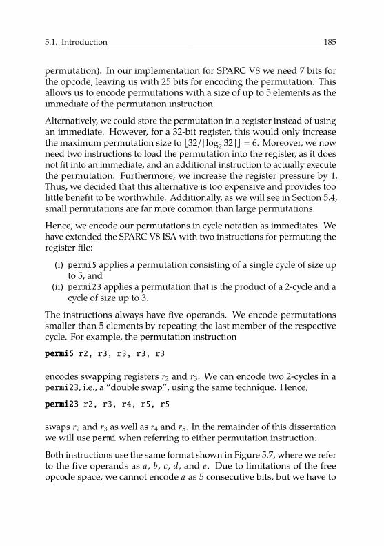
5.1. Introduction 185
permutation). In our implementation for SPARC V8 we need 7 bits forthe opcode, leaving us with 25 bits for encoding the permutation. Thisallows us to encode permutations with a size of up to 5 elements as theimmediate of the permutation instruction.
Alternatively, we could store the permutation in a register instead of usingan immediate. However, for a 32-bit register, this would only increasethe maximum permutation size to b32/dlog2 32ec � 6. Moreover, we nowneed two instructions to load the permutation into the register, as it doesnot fit into an immediate, and an additional instruction to actually executethe permutation. Furthermore, we increase the register pressure by 1.Thus, we decided that this alternative is too expensive and provides toolittle benefit to be worthwhile. Additionally, as we will see in Section 5.4,small permutations are far more common than large permutations.
Hence, we encode our permutations in cycle notation as immediates. Wehave extended the SPARC V8 ISA with two instructions for permuting theregister file:
(i) permi5 applies a permutation consisting of a single cycle of size upto 5, and
(ii) permi23 applies a permutation that is the product of a 2-cycle and acycle of size up to 3.
The instructions always have five operands. We encode permutationssmaller than 5 elements by repeating the last member of the respectivecycle. For example, the permutation instruction
permi5 r2, r3, r3, r3, r3
encodes swapping registers r2 and r3. We can encode two 2-cycles in apermi23, i.e., a “double swap”, using the same technique. Hence,
permi23 r2, r3, r4, r5, r5
swaps r2 and r3 as well as r4 and r5. In the remainder of this dissertationwe will use permiwhen referring to either permutation instruction.
Both instructions use the same format shown in Figure 5.7, where we referto the five operands as a, b, c, d, and e. Due to limitations of the freeopcode space, we cannot encode a as 5 consecutive bits, but we have to
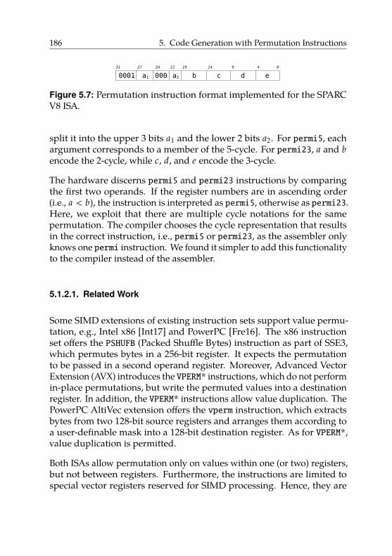
186 5. Code Generation with Permutation Instructions
0001 000a1 b c d e31 27 21 19 14 9 4 0
a2
24
Figure 5.7: Permutation instruction format implemented for the SPARCV8 ISA.
split it into the upper 3 bits a1 and the lower 2 bits a2. For permi5, eachargument corresponds to a member of the 5-cycle. For permi23, a and bencode the 2-cycle, while c, d, and e encode the 3-cycle.
The hardware discerns permi5 and permi23 instructions by comparingthe first two operands. If the register numbers are in ascending order(i.e., a < b), the instruction is interpreted as permi5, otherwise as permi23.Here, we exploit that there are multiple cycle notations for the samepermutation. The compiler chooses the cycle representation that resultsin the correct instruction, i.e., permi5 or permi23, as the assembler onlyknows one permi instruction. We found it simpler to add this functionalityto the compiler instead of the assembler.
5.1.2.1. Related Work
Some SIMD extensions of existing instruction sets support value permu-tation, e.g., Intel x86 [Int17] and PowerPC [Fre16]. The x86 instructionset offers the PSHUFB (Packed Shuffle Bytes) instruction as part of SSE3,which permutes bytes in a 256-bit register. It expects the permutationto be passed in a second operand register. Moreover, Advanced VectorExtension (AVX) introduces the VPERM* instructions, which do not performin-place permutations, but write the permuted values into a destinationregister. In addition, the VPERM* instructions allow value duplication. ThePowerPC AltiVec extension offers the vperm instruction, which extractsbytes from two 128-bit source registers and arranges them according toa user-definable mask into a 128-bit destination register. As for VPERM*,value duplication is permitted.
Both ISAs allow permutation only on values within one (or two) registers,but not between registers. Furthermore, the instructions are limited tospecial vector registers reserved for SIMD processing. Hence, they are
5.2. Hardware Implementation 187
unsuitable for implementing RTGs. In contrast, our proposed permutationinstructions work on general-purpose registers.
Instructions of VLIW architectures include one operation per functionalunit of the processor. Hence, on a 4-way VLIW architecture it may bepossible to encode 4 swaps or 4 copies in one instruction. In contrast, ourproposed permutation instructions target a non-VLIW architecture.
5.2. Hardware Implementation
This section describes the hardware implementation of our permutationinstructions. The details of the hardware implementation are not necessaryto follow the discussion of code-generation approaches in Section 5.3.Hence, the reader may skip this section. Still, we provide an overview ofthe hardware implementation for the sake of completeness.
The hardware implementation we describe in this section is not a contribu-tion of this dissertation. The complete hardware was implemented by LarsBauer, Artjom Grudnitsky, Tobias Modschiedler, and Jörg Henkel [Moh+13].The content in this section is based on an unpublished extended versionof [Moh+13]. Modschiedler [Mod13] gives the most extensive descriptionof the hardware implementation available.
5.2.1. Fundamental Pipeline Modifications
The underlying processor for the implementation is a Gaisler LEON 3 [Cob17b].The LEON 3 uses an in-order 7-stage pipeline. As an example, Figure 5.8shows the processing of an add instruction.
The pipeline stages have the following tasks:
Fetch Retrieve the instruction word from the instruction cache.Decode Extract instruction type as well as operand and destination
registers from the instruction word. Use the operand registers asaddress inputs to the register file (one cycle latency for read or writeaccess).
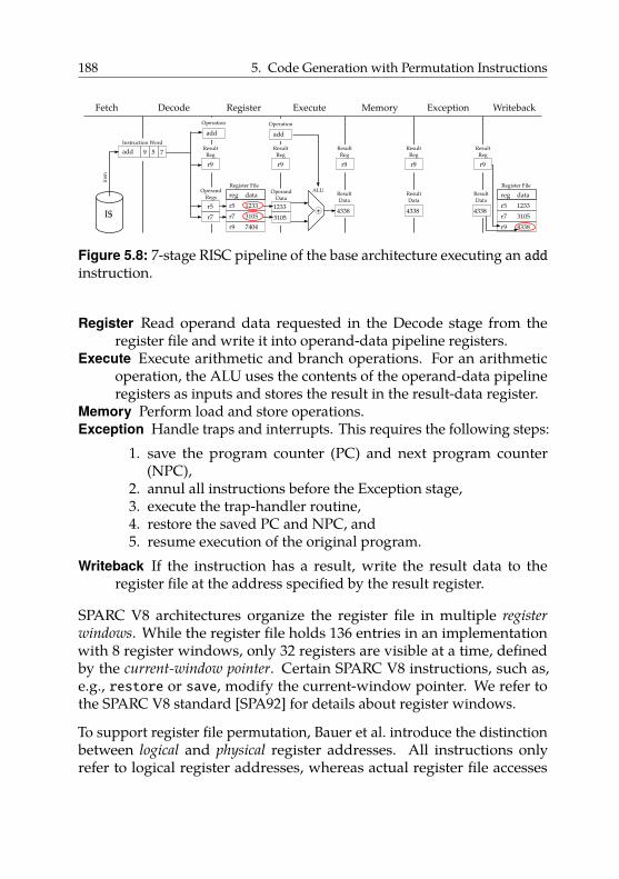
188 5. Code Generation with Permutation Instructions
Fetch Decode Register Execute Memory Exception Writeback
I$
insn
reg data
r5 1233
r7 3105
r9 7404
OperandRegs
r5
r7
OperandData
1233
31054338
ResultData
+ 4338
ResultData
4338
ResultData
add
Operation
add
Operation
5 7add 9
Instruction Word
Register File
reg data
r5 1233
r7 3105
r9 4338
Register FileALU
ResultReg
r9
ResultReg
r9
ResultReg
r9
ResultReg
r9
ResultReg
r9
Figure 5.8: 7-stage RISC pipeline of the base architecture executing an addinstruction.
Register Read operand data requested in the Decode stage from theregister file and write it into operand-data pipeline registers.
Execute Execute arithmetic and branch operations. For an arithmeticoperation, the ALU uses the contents of the operand-data pipelineregisters as inputs and stores the result in the result-data register.
Memory Perform load and store operations.Exception Handle traps and interrupts. This requires the following steps:
1. save the program counter (PC) and next program counter(NPC),
2. annul all instructions before the Exception stage,3. execute the trap-handler routine,4. restore the saved PC and NPC, and5. resume execution of the original program.
Writeback If the instruction has a result, write the result data to theregister file at the address specified by the result register.
SPARC V8 architectures organize the register file in multiple register
windows. While the register file holds 136 entries in an implementationwith 8 register windows, only 32 registers are visible at a time, definedby the current-window pointer. Certain SPARC V8 instructions, such as,e.g., restore or save, modify the current-window pointer. We refer tothe SPARC V8 standard [SPA92] for details about register windows.
To support register file permutation, Bauer et al. introduce the distinctionbetween logical and physical register addresses. All instructions onlyrefer to logical register addresses, whereas actual register file accesses
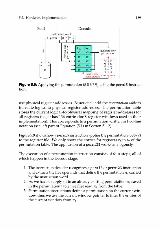
5.2. Hardware Implementation 189
Fetch Decode
I$
insn
8 6permi 5
Instruction Word
log phys
r5
r6
r7
r5
r6
r7
retr
iev
e o
ldp
erm
uta
tio
n
7 9
r8 r9
r9 r8
generate newpermutation
r5 → r8r6 → r9r7 → r6r8 → r5r9 → r7
write newpermutation
Figure 5.9: Applying the permutation (5 8 6 7 9) using the permi5 instruc-tion.
use physical register addresses. Bauer et al. add the permutation table totranslate logical to physical register addresses. The permutation tablestores the current logical-to-physical mapping of register addresses forall registers (i.e., it has 136 entries for 8 register windows used in theirimplementation). This corresponds to a permutation written in two-linenotation (see left part of Equation (5.1) in Section 5.1.2).
Figure 5.9 shows how a permi5 instruction applies the permutation (58679)to the register file. We only show the entries for registers r5 to r9 of thepermutation table. The application of a permi23works analogously.
The execution of a permutation instruction consists of four steps, all ofwhich happen in the Decode stage:
1. The instruction decoder recognizes a permi5 or permi23 instructionand extracts the five operands that define the permutation πi carriedby the instruction word.
2. As we have to apply πi to an already existing permutation πt savedin the permutation table, we first read πt from the table.
3. Permutation instructions define a permutation on the current win-dow, thus we use the current window pointer to filter the entries ofthe current window from πt .
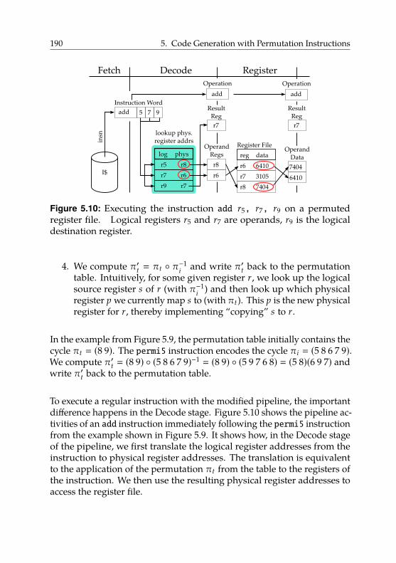
190 5. Code Generation with Permutation Instructions
Fetch Decode Register
I$
insn
reg data
r6 6410
r7 3105
r8 7404
OperandRegs
r8
r6
OperandData
7404
6410
add
Operation
add
Operation
7 9add 5
Instruction Word
Register File
log phys
r5
r7
r9
r8
r6
r7
ResultReg
r7
ResultReg
r7lookup phys.register addrs
Figure 5.10: Executing the instruction add r5, r7, r9 on a permutedregister file. Logical registers r5 and r7 are operands, r9 is the logicaldestination register.
4. We compute π′t � πt ◦ π−1i and write π′t back to the permutation
table. Intuitively, for some given register r, we look up the logicalsource register s of r (with π−1
i ) and then look up which physicalregister p we currently map s to (with πt). This p is the new physicalregister for r, thereby implementing “copying” s to r.
In the example from Figure 5.9, the permutation table initially contains thecycle πt � (8 9). The permi5 instruction encodes the cycle πi � (5 8 6 7 9).We compute π′t � (8 9) ◦ (5 8 6 7 9)−1 � (8 9) ◦ (5 9 7 6 8) � (5 8)(6 9 7) andwrite π′t back to the permutation table.
To execute a regular instruction with the modified pipeline, the importantdifference happens in the Decode stage. Figure 5.10 shows the pipeline ac-tivities of an add instruction immediately following the permi5 instructionfrom the example shown in Figure 5.9. It shows how, in the Decode stageof the pipeline, we first translate the logical register addresses from theinstruction to physical register addresses. The translation is equivalentto the application of the permutation πt from the table to the registers ofthe instruction. We then use the resulting physical register addresses toaccess the register file.

5.2. Hardware Implementation 191
Permutation instructions do not induce read-after-write hazards in thepipeline, thus Bauer et al. do not have to extend the pipeline-forwardinglogic. This is because permutation instructions commit their changesin the Decode stage. Hence, once the following instruction (add in theexample) is in the Decode stage one cycle later, the permutation table hasalready been updated with the new permutation. Bauer et al. call thischaracteristic early committing.
At system reset, they initialize the permutation table with the identitypermutation, i.e., the physical address of each register is the same asits logical address. Subsequent permutation instructions modify thepermutation table. Permutations are transparent to the operating system(OS), so Bauer et al. do not need to modify OS code for context switches.For instance, if the OS wants to save r5 from a task (to restore it later), itwill actually access the physical register that currently holds the value ofr5 (which is r8 in Figure 5.10). When restoring r5 later, it may be writtento a different register; however, an access to r5 will provide the same datathat was initially saved.
5.2.2. Exception Handling
The architecture outlined in the previous section can execute programsthat use permutation instructions, unless traps occur during execution.The SPARC V8 standard specifies three categories of traps:
1. Precise traps are induced by particular instructions, e.g., unknowninstructions, trap-on-condition instructions or instructions causinga register-window overflow or underflow.
2. Deferred traps are caused by floating-point and co-processor instruc-tions and become visible after the instruction that caused them hascommitted.
3. Interrupting traps are caused by external interrupts, e.g., timerinterrupts or I/O components notifying the processor that a bufferis full.
A program that runs directly on the hardware (without an OS), doesnot use any I/O components, and uses the register windows in a way
192 5. Code Generation with Permutation Instructions
that incurs neither window overflows nor underflows42 will not causeany traps. However, when executing on a multi-tasking OS, the programis likely to be interrupted, e.g., by the timer used to periodically invokethe OS scheduler, by the page fault handler or by interrupts caused byperipherals.
The underlying architecture handles traps in the Exception stage. Af-ter the trap-handler code has finished, the program counter and nextprogram counter are restored and regular program execution continues.Instructions must not be executed twice, i.e., instructions already in thepipeline before the trap is detected must not first proceed through thepipeline at the start of the trap handler and then be executed again afterthe old program counter is restored and the corresponding instruction isreloaded.
Therefore, at the time of trap detection, the pipeline automatically annulsall instructions that are currently in pipeline stages Exception or earlier.This ensures that they are executed only once: after trap handling hasfinished, the old program counter is restored and the instructions areloaded into the pipeline again.
However, Bauer et al. cannot simply annul permutation instructions asdescribed above, as, due to their early committing characteristic, theseinstructions already modify the permutation table in the Decode stage.Hence, they differentiate between three cases for annulling permutationinstructions during a trap:
1. They flag permutations in the Fetch stage with an annul bit. Permu-tations marked this way do not update the permutation table in theDecode stage.
2. They notify permutations in the Decode stage with a cancel signal.They send the cancel signal at the time they detect a trap in theException stage. If they see the cancel signal in the Decode stage,they create the new permutation π′t but do not write it back to thepermutation table.
42This is possible by compiling the program in a way that does not change the registerwindow during function calls. This is often called a “flat” register model. For GCC, theoption -mflat enables the flat register model.
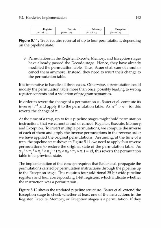
5.2. Hardware Implementation 193
Register Execute Memory Exceptionpermi π3 permi π2 permi π1permi π4
Figure 5.11: Traps require reversal of up to four permutations, dependingon the pipeline state.
3. Permutations in the Register, Execute, Memory, and Exception stageshave already passed the Decode stage. Hence, they have alreadymodified the permutation table. Thus, Bauer et al. cannot annul orcancel them anymore. Instead, they need to revert their change tothe permutation table.
It is imperative to handle all three cases. Otherwise, a permutation couldmodify the permutation table more than once, possibly leading to wrongregister contents and a violation of program semantics.
In order to revert the change of a permutation π, Bauer et al. compute itsinverse π−1 and apply it to the permutation table. As π−1 ◦ π � id, thisreverts the change of π.
At the time of a trap, up to four pipeline stages might hold permutationinstructions that we cannot annul or cancel: Register, Execute, Memory,and Exception. To invert multiple permutations, we compute the inverseof each of them and apply the inverse permutations in the reverse orderwe have applied the original permutations. Assuming, at the time of atrap, the pipeline state shown in Figure 5.11, we need to apply four inversepermutations to restore the original state of the permutation table. Asπ−1
1 ◦π−12 ◦π−1
3 ◦π−14 ◦ (π4 ◦π3 ◦π2 ◦π1) � id, this reverts the permutation
table to its previous state.
The implementation of this concept requires that Bauer et al. propagate thepermutations carried by permutation instructions through the pipeline upto the Exception stage. This requires four additional 25-bit wide pipelineregisters and four corresponding 1-bit registers, which indicate whetherthe instruction was a permutation.
Figure 5.12 shows the updated pipeline structure. Bauer et al. extend theException stage to check whether at least one of the instructions in theRegister, Execute, Memory, or Exception stages is a permutation. If they
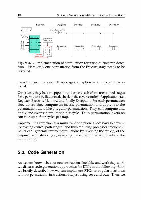
194 5. Code Generation with Permutation Instructions
Decode
- --
log phys
r5
r6
r7
r8
r9
r6
- -
r8 r5
r9 r7
generate newpermutation
r5 → r5r6 → r6r7 → r7r8 → r9r9 → r8write new
permutation
Register Execute Memory Exception
Permutation
- -- - -
inverted permutation
9 75 6 8
6 78
Permutation
9 5
Permutation
- -- - -
Permutation
- -- - -retr
iev
e o
ldp
erm
uta
tio
n
select
Figure 5.12: Implementation of permutation reversion during trap detec-tion. Here, only one permutation from the Execute stage needs to bereverted.
detect no permutations in these stages, exception handling continues asusual.
Otherwise, they halt the pipeline and check each of the mentioned stagesfor a permutation. Bauer et al. check in the reverse order of application, i.e.,Register, Execute, Memory, and finally Exception. For each permutationthey detect, they compute an inverse permutation and apply it to thepermutation table like a regular permutation. They can compute andapply one inverse permutation per cycle. Thus, permutation inversioncan take up to four cycles per trap.
Implementing inversion as a multi-cycle operation is necessary to preventincreasing critical path length (and thus reducing processor frequency).Bauer et al. generate inverse permutations by reversing the cycle(s) of theoriginal permutation (i.e., reversing the order of the arguments of thepermutation).
5.3. Code Generation
As we now know what our new instructions look like and work they work,we discuss code-generation approaches for RTGs in the following. First,we briefly describe how we can implement RTGs on regular machineswithout permutation instructions, i.e., just using copy and swap. Then, we
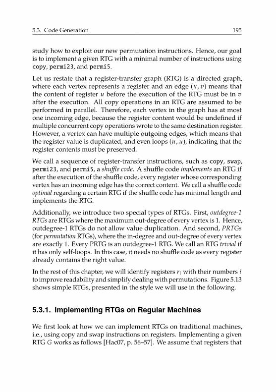
5.3. Code Generation 195
study how to exploit our new permutation instructions. Hence, our goalis to implement a given RTG with a minimal number of instructions usingcopy, permi23, and permi5.
Let us restate that a register-transfer graph (RTG) is a directed graph,where each vertex represents a register and an edge (u , v) means thatthe content of register u before the execution of the RTG must be in vafter the execution. All copy operations in an RTG are assumed to beperformed in parallel. Therefore, each vertex in the graph has at mostone incoming edge, because the register content would be undefined ifmultiple concurrent copy operations wrote to the same destination register.However, a vertex can have multiple outgoing edges, which means thatthe register value is duplicated, and even loops (u , u), indicating that theregister contents must be preserved.
We call a sequence of register-transfer instructions, such as copy, swap,permi23, and permi5, a shuffle code. A shuffle code implements an RTG ifafter the execution of the shuffle code, every register whose correspondingvertex has an incoming edge has the correct content. We call a shuffle codeoptimal regarding a certain RTG if the shuffle code has minimal length andimplements the RTG.
Additionally, we introduce two special types of RTGs. First, outdegree-1
RTGs are RTGs where the maximum out-degree of every vertex is 1. Hence,outdegree-1 RTGs do not allow value duplication. And second, PRTGs
(for permutation RTGs), where the in-degree and out-degree of every vertexare exactly 1. Every PRTG is an outdegree-1 RTG. We call an RTG trivial ifit has only self-loops. In this case, it needs no shuffle code as every registeralready contains the right value.
In the rest of this chapter, we will identify registers ri with their numbers ito improve readability and simplify dealing with permutations. Figure 5.13shows simple RTGs, presented in the style we will use in the following.
5.3.1. Implementing RTGs on Regular Machines
We first look at how we can implement RTGs on traditional machines,i.e., using copy and swap instructions on registers. Implementing a givenRTG G works as follows [Hac07, p. 56–57]. We assume that registers that
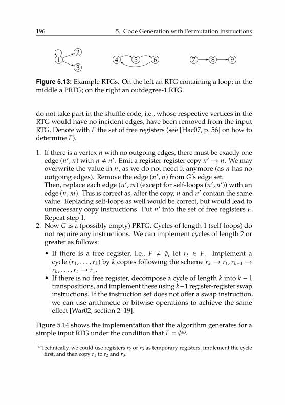
196 5. Code Generation with Permutation Instructions
12
34 5 6 7 8 9
Figure 5.13: Example RTGs. On the left an RTG containing a loop; in themiddle a PRTG; on the right an outdegree-1 RTG.
do not take part in the shuffle code, i.e., whose respective vertices in theRTG would have no incident edges, have been removed from the inputRTG. Denote with F the set of free registers (see [Hac07, p. 56] on how todetermine F).
1. If there is a vertex n with no outgoing edges, there must be exactly oneedge (n′, n) with n , n′. Emit a register-register copy n′→ n. We mayoverwrite the value in n, as we do not need it anymore (as n has nooutgoing edges). Remove the edge (n′, n) from G’s edge set.Then, replace each edge (n′,m) (except for self-loops (n′, n′)) with anedge (n ,m). This is correct as, after the copy, n and n′ contain the samevalue. Replacing self-loops as well would be correct, but would lead tounnecessary copy instructions. Put n′ into the set of free registers F.Repeat step 1.
2. Now G is a (possibly empty) PRTG. Cycles of length 1 (self-loops) donot require any instructions. We can implement cycles of length 2 orgreater as follows:• If there is a free register, i.e., F , ∅, let rt ∈ F. Implement a
cycle (r1 , . . . , rk) by k copies following the scheme rk → rt , rk−1 →rk , . . . , rt → r1.
• If there is no free register, decompose a cycle of length k into k − 1transpositions, and implement these using k−1 register-register swapinstructions. If the instruction set does not offer a swap instruction,we can use arithmetic or bitwise operations to achieve the sameeffect [War02, section 2–19].
Figure 5.14 shows the implementation that the algorithm generates for asimple input RTG under the condition that F � ∅43.
43Technically, we could use registers r2 or r3 as temporary registers, implement the cyclefirst, and then copy r1 to r2 and r3.
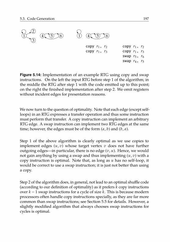
5.3. Code Generation 197
12
34 5 6 1 4 5 6
copy r1, r2copy r1, r3
copy r1, r2copy r1, r3swap r5, r6swap r4, r5
Figure 5.14: Implementation of an example RTG using copy and swapinstructions. On the left the input RTG before step 1 of the algorithm; inthe middle the RTG after step 1 with the code emitted up to this point;on the right the finished implementation after step 2. We omit registerswithout incident edges for presentation reasons.
We now turn to the question of optimality. Note that each edge (except self-loops) in an RTG expresses a transfer operation and thus some instructionmust perform that transfer. A copy instruction can implement an arbitraryRTG edge. A swap instruction can implement two RTG edges at the sametime; however, the edges must be of the form (a , b) and (b , a).
Step 1 of the above algorithm is clearly optimal as we use copies toimplement edges (u , v) whose target vertex v does not have furtheroutgoing edges—in particular, there is no edge (v , u). Hence, we wouldnot gain anything by using a swap and thus implementing (u , v)with acopy instruction is optimal. Note that, as long as u has no self-loop, itwould be correct to use a swap instruction; it is just not better than usinga copy.
Step 2 of the algorithm does, in general, not lead to an optimal shuffle code(according to our definition of optimality) as it prefers k copy instructionsover k − 1 swap instructions for a cycle of size k. This is because modernprocessors often handle copy instructions specially, as they are far morecommon than swap instructions; see Section 5.5 for details. However, aslightly modified algorithm that always chooses swap instructions forcycles is optimal.
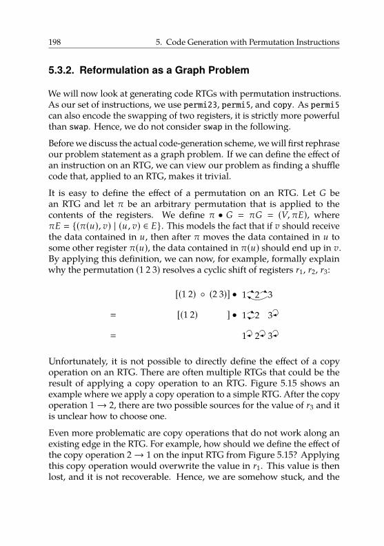
198 5. Code Generation with Permutation Instructions
5.3.2. Reformulation as a Graph Problem
We will now look at generating code RTGs with permutation instructions.As our set of instructions, we use permi23, permi5, and copy. As permi5can also encode the swapping of two registers, it is strictly more powerfulthan swap. Hence, we do not consider swap in the following.
Before we discuss the actual code-generation scheme, we will first rephraseour problem statement as a graph problem. If we can define the effect ofan instruction on an RTG, we can view our problem as finding a shufflecode that, applied to an RTG, makes it trivial.
It is easy to define the effect of a permutation on an RTG. Let G bean RTG and let π be an arbitrary permutation that is applied to thecontents of the registers. We define π • G � πG � (V, πE), whereπE � {(π(u), v) | (u , v) ∈ E}. This models the fact that if v should receivethe data contained in u, then after π moves the data contained in u tosome other register π(u), the data contained in π(u) should end up in v.By applying this definition, we can now, for example, formally explainwhy the permutation (1 2 3) resolves a cyclic shift of registers r1, r2, r3:
[(1 2) ◦ (2 3)] • 1 2 3
� [(1 2) ] • 1 2 3
� 1 2 3
Unfortunately, it is not possible to directly define the effect of a copyoperation on an RTG. There are often multiple RTGs that could be theresult of applying a copy operation to an RTG. Figure 5.15 shows anexample where we apply a copy operation to a simple RTG. After the copyoperation 1→ 2, there are two possible sources for the value of r3 and itis unclear how to choose one.
Even more problematic are copy operations that do not work along anexisting edge in the RTG. For example, how should we define the effect ofthe copy operation 2→ 1 on the input RTG from Figure 5.15? Applyingthis copy operation would overwrite the value in r1. This value is thenlost, and it is not recoverable. Hence, we are somehow stuck, and the
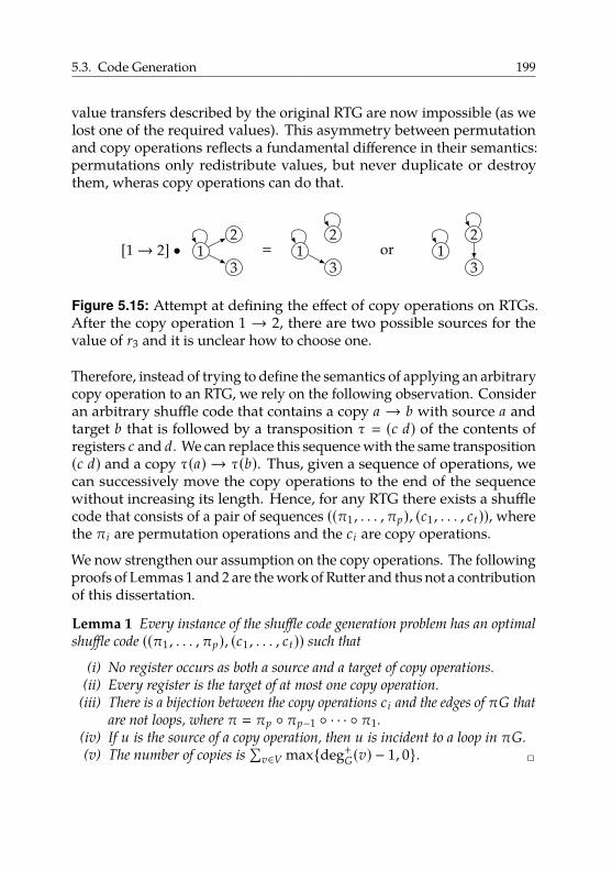
5.3. Code Generation 199
value transfers described by the original RTG are now impossible (as welost one of the required values). This asymmetry between permutationand copy operations reflects a fundamental difference in their semantics:permutations only redistribute values, but never duplicate or destroythem, wheras copy operations can do that.
[1→ 2] • 12
3� 1
2
3or 1
2
3
Figure 5.15: Attempt at defining the effect of copy operations on RTGs.After the copy operation 1 → 2, there are two possible sources for thevalue of r3 and it is unclear how to choose one.
Therefore, instead of trying to define the semantics of applying an arbitrarycopy operation to an RTG, we rely on the following observation. Consideran arbitrary shuffle code that contains a copy a → b with source a andtarget b that is followed by a transposition τ � (c d) of the contents ofregisters c and d. We can replace this sequence with the same transposition(c d) and a copy τ(a) → τ(b). Thus, given a sequence of operations, wecan successively move the copy operations to the end of the sequencewithout increasing its length. Hence, for any RTG there exists a shufflecode that consists of a pair of sequences ((π1 , . . . , πp), (c1 , . . . , ct)), wherethe πi are permutation operations and the ci are copy operations.
We now strengthen our assumption on the copy operations. The followingproofs of Lemmas 1 and 2 are the work of Rutter and thus not a contributionof this dissertation.
Lemma 1 Every instance of the shuffle code generation problem has an optimal
shuffle code ((π1 , . . . , πp), (c1 , . . . , ct)) such that
(i) No register occurs as both a source and a target of copy operations.
(ii) Every register is the target of at most one copy operation.
(iii) There is a bijection between the copy operations ci and the edges of πG that
are not loops, where π � πp ◦ πp−1 ◦ · · · ◦ π1.
(iv) If u is the source of a copy operation, then u is incident to a loop in πG.
(v) The number of copies is
∑v∈V max{deg+
G(v) − 1, 0}. 2
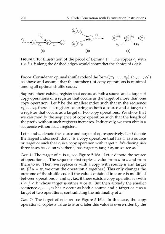
200 5. Code Generation with Permutation Instructions
u v wckci
c j
c j
(a)
u
vw
ck
cic j
(b)
v wck ci xc jc j
(c)
Figure 5.16: Illustration of the proof of Lemma 1. The copies c j withi < j < k along the dashed edges would contradict the choice of i or k.
Proof Consider an optimal shuffle code of the form ((π1 , . . . , πp), (c1 , . . . , ct))as above and assume that the number t of copy operations is minimalamong all optimal shuffle codes.
Suppose there exists a register that occurs as both a source and a target ofcopy operations or a register that occurs as the target of more than onecopy operation. Let k be the smallest index such that in the sequencec1 , . . . , ck there is a register occurring as both a source and a target ora register that occurs as a target of two copy operations. We show thatwe can modify the sequence of copy operation such that the length ofthe prefix without such registers increases. Inductively, we then obtain asequence without such registers.
Let v and w denote the source and target of ck , respectively. Let i denotethe largest index such that ci is a copy operation that has w as a sourceor target or such that ci is a copy operation with target v. We distinguishthree cases based on whether ci has target v, target w, or source w.
Case 1: The target of ci is v; see Figure 5.16a. Let u denote the sourceof operation ci . The sequence first copies a value from u to v and fromthere to w. Then, we replace ck with a copy with source u and targetw. (If u � w, we omit the operation altogether.) This only changes theoutcome of the shuffle code if the value contained in u or v is modifiedbetween operations ci and ck , i.e., if there exists a copy operation c j withi < j < k whose target is either u or v. But then already the smallersequence c1 , . . . , c j has u occur as both a source and a target or v as atarget of two operations, contradicting the minimality of k.
Case 2: The target of ci is w; see Figure 5.16b. In this case, the copyoperation ci copies a value to w and later this value is overwritten by the
5.3. Code Generation 201
operation ck . Note that by the choice of i there is no operation c j withi < j < k with source w. Thus, omitting the copy operation ci does notchange the outcome of the shuffle code. A contradiction to optimality.
Case 3: The source of ci is w; see Figure 5.16c. Let x denote the targetof operation ci . In this case, first a value is copied from w to x and laterthe value in v is copied to w. We claim that no copy operation c j withi < j < k involves x or w. If x occurs as the source of c j , then x occurs as asource and target in the sequence c1 , . . . , c j . If x occurs as the target of c j ,then x occurs twice as a target in c1 , . . . , c j . In both cases, this contradictsthe minimality of k. If w is the target of c j , then w occurs as a source anda target in the sequence c1 , . . . , c j , contradicting the choice of k. If w is thesource of c j we have a contradiction to the choice of i. This proves theclaim.
We can thus, without changing the outcome of the shuffle code, movethe operation ci immediately before the operation ck . Then, our sequencecontains consecutive copy operations w → x and v → w. Replace thesetwo operations with a cyclic shift of { v, w, x } and a copy operation w → v.This decreases the number of copy operations by 1 and thus contradictsthe minimality of t.
Altogether, in each case, we have either found a contradiction to theoptimality of the shuffle code, to the minimality of the number of copyoperations, or we have succeeded in producing a shuffle code that has alonger prefix satisfying properties (i) and (ii). Inductively, we obtain ashuffle code satisfying both (i) and (ii). Fix such a code. Since no registeris both source and target of a copy operation, the copy operations arecommutative and can be reordered arbitrarily without changing the result.
For property (iii) first observe that the only way to transfer a value fromu to v is via a copy operation u → v. This is due to the facts that theshuffle code is correct, that no node occurs as both a source and a targetof copy operations, and that π only permutes the values in the initialregisters but does not duplicate them. Thus, for every edge there mustbe a corresponding copy operation. Conversely, this number of copyoperations certainly suffices for a correct shuffle code for πG.
For property (iv) consider a copy operation from u to v such that u is notincident to a loop. If the indegree of v in πG were 1, then there would
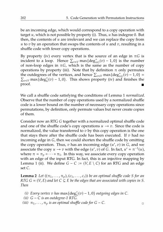
202 5. Code Generation with Permutation Instructions
be an incoming edge, which would correspond to a copy operation withtarget u, which is not possible by property (i). Thus, u has indegree 0. Butthen, the contents of u are irrelevant and we can replace the copy fromu to v by an operation that swaps the contents of u and v, resulting in ashuffle code with fewer copy operations.
By property (iv) every vertex that is the source of an edge in πG isincident to a loop. Hence
∑v∈V max{deg+
πG(v) − 1, 0} is the numberof non-loop edges in πG, which is the same as the number of copyoperations by property (iii). Note that by definition π only permutesthe outdegrees of the vertices, and hence
∑v∈V max{deg+
πG(v) − 1, 0} �∑v∈V max{deg+
G(v) − 1, 0}. This shows property (iv) and finishes theproof. �
We call a shuffle code satisfying the conditions of Lemma 1 normalized.Observe that the number of copy operations used by a normalized shufflecode is a lower bound on the number of necessary copy operations sincepermutations, by definition, only permute values but never create copiesof them.
Consider now an RTG G together with a normalized optimal shuffle codeand one of the shuffle code’s copy operations u → v. Since the code isnormalized, the value transferred to v by this copy operation is the onethat stays there after the shuffle code has been executed. If v had noincoming edge in G, then we could shorten the shuffle code by omittingthe copy operation. Thus, v has an incoming edge (u′, v) in G, and weassociate the copy u → v with the edge (u′, v) of G. In fact, u′ � π−1(u),where π � πp ◦ · · · ◦ π1. In this way, we associate every copy operationwith an edge of the input RTG. In fact, this is an injective mapping byLemma 1 (ii). We define G − C :� (V, E \ C) for an RTG and an edgeset C.
Lemma 2 Let ((π1 , . . . , πp), (c1 , . . . , ct)) be an optimal shuffle code S for an
RTG G � (V, E) and let C ⊆ E be the edges that are associated with copies in S.
Then
(i) Every vertex v has max{deg+
G(v) − 1, 0} outgoing edges in C.
(ii) G − C is an outdegree-1 RTG.
(iii) π1 , . . . , πp is an optimal shuffle code for G − C. 2
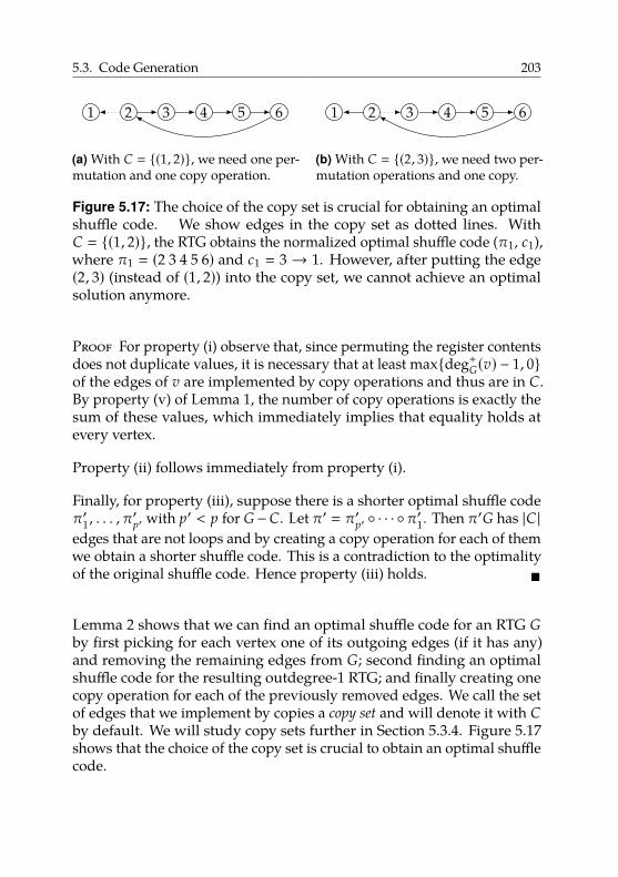
5.3. Code Generation 203
1 2 3 4 5 6
(a) With C � {(1, 2)}, we need one per-mutation and one copy operation.
1 2 3 4 5 6
(b) With C � {(2, 3)}, we need two per-mutation operations and one copy.
Figure 5.17: The choice of the copy set is crucial for obtaining an optimalshuffle code. We show edges in the copy set as dotted lines. WithC � {(1, 2)}, the RTG obtains the normalized optimal shuffle code (π1, c1),where π1 � (2 3 4 5 6) and c1 � 3→ 1. However, after putting the edge(2, 3) (instead of (1, 2)) into the copy set, we cannot achieve an optimalsolution anymore.
Proof For property (i) observe that, since permuting the register contentsdoes not duplicate values, it is necessary that at least max{deg+
G(v) − 1, 0}of the edges of v are implemented by copy operations and thus are in C.By property (v) of Lemma 1, the number of copy operations is exactly thesum of these values, which immediately implies that equality holds atevery vertex.
Property (ii) follows immediately from property (i).
Finally, for property (iii), suppose there is a shorter optimal shuffle codeπ′1 , . . . , π
′p′ with p′ < p for G−C. Let π′ � π′p′ ◦ · · · ◦π′1. Then π′G has |C |
edges that are not loops and by creating a copy operation for each of themwe obtain a shorter shuffle code. This is a contradiction to the optimalityof the original shuffle code. Hence property (iii) holds. �
Lemma 2 shows that we can find an optimal shuffle code for an RTG Gby first picking for each vertex one of its outgoing edges (if it has any)and removing the remaining edges from G; second finding an optimalshuffle code for the resulting outdegree-1 RTG; and finally creating onecopy operation for each of the previously removed edges. We call the setof edges that we implement by copies a copy set and will denote it with Cby default. We will study copy sets further in Section 5.3.4. Figure 5.17shows that the choice of the copy set is crucial to obtain an optimal shufflecode.
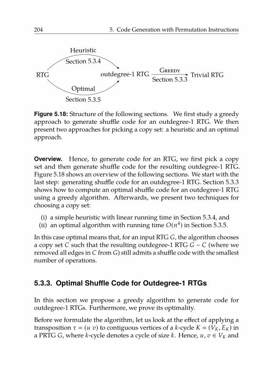
204 5. Code Generation with Permutation Instructions
RTG outdegree-1 RTG Trivial RTG
Heuristic
Section 5.3.4
OptimalSection 5.3.5
GreedySection 5.3.3
Figure 5.18: Structure of the following sections. We first study a greedyapproach to generate shuffle code for an outdegree-1 RTG. We thenpresent two approaches for picking a copy set: a heuristic and an optimalapproach.
Overview. Hence, to generate code for an RTG, we first pick a copyset and then generate shuffle code for the resulting outdegree-1 RTG.Figure 5.18 shows an overview of the following sections. We start with thelast step: generating shuffle code for an outdegree-1 RTG. Section 5.3.3shows how to compute an optimal shuffle code for an outdegree-1 RTGusing a greedy algorithm. Afterwards, we present two techniques forchoosing a copy set:
(i) a simple heuristic with linear running time in Section 5.3.4, and(ii) an optimal algorithm with running time O(n4) in Section 5.3.5.
In this case optimal means that, for an input RTG G, the algorithm choosesa copy set C such that the resulting outdegree-1 RTG G − C (where weremoved all edges in C from G) still admits a shuffle code with the smallestnumber of operations.
5.3.3. Optimal Shuffle Code for Outdegree-1 RTGs
In this section we propose a greedy algorithm to generate code foroutdegree-1 RTGs. Furthermore, we prove its optimality.
Before we formulate the algorithm, let us look at the effect of applying atransposition τ � (u v) to contiguous vertices of a k-cycle K � (VK , EK) ina PRTG G, where k-cycle denotes a cycle of size k. Hence, u , v ∈ VK and
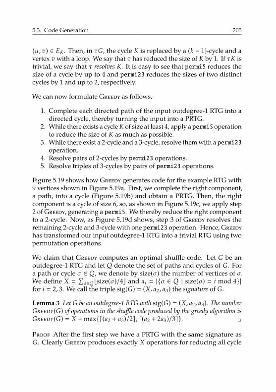
5.3. Code Generation 205
(u , v) ∈ EK . Then, in τG, the cycle K is replaced by a (k − 1)-cycle and avertex v with a loop. We say that τ has reduced the size of K by 1. If τK istrivial, we say that τ resolves K. It is easy to see that permi5 reduces thesize of a cycle by up to 4 and permi23 reduces the sizes of two distinctcycles by 1 and up to 2, respectively.
We can now formulate Greedy as follows.
1. Complete each directed path of the input outdegree-1 RTG into adirected cycle, thereby turning the input into a PRTG.
2. While there exists a cycle K of size at least 4, apply a permi5 operationto reduce the size of K as much as possible.
3. While there exist a 2-cycle and a 3-cycle, resolve them with a permi23operation.
4. Resolve pairs of 2-cycles by permi23 operations.5. Resolve triples of 3-cycles by pairs of permi23 operations.
Figure 5.19 shows how Greedy generates code for the example RTG with9 vertices shown in Figure 5.19a. First, we complete the right component,a path, into a cycle (Figure 5.19b) and obtain a PRTG. Then, the rightcomponent is a cycle of size 6, so, as shown in Figure 5.19c, we apply step2 of Greedy, generating a permi5. We thereby reduce the right componentto a 2-cycle. Now, as Figure 5.19d shows, step 3 of Greedy resolves theremaining 2-cycle and 3-cycle with one permi23 operation. Hence, Greedyhas transformed our input outdegree-1 RTG into a trivial RTG using twopermutation operations.
We claim that Greedy computes an optimal shuffle code. Let G be anoutdegree-1 RTG and let Q denote the set of paths and cycles of G. Fora path or cycle σ ∈ Q, we denote by size(σ) the number of vertices of σ.We define X �
∑σ∈Q bsize(σ)/4c and ai � |{σ ∈ Q | size(σ) � i mod 4}|
for i � 2, 3. We call the triple sig(G) � (X, a2 , a3) the signature of G.
Lemma 3 Let G be an outdegree-1 RTG with sig(G) � (X, a2 , a3). The number
Greedy(G) of operations in the shuffle code produced by the greedy algorithm is
Greedy(G) � X + max{d(a2 + a3)/2e , d(a2 + 2a3)/3e}. 2
Proof After the first step we have a PRTG with the same signature asG. Clearly Greedy produces exactly X operations for reducing all cycle
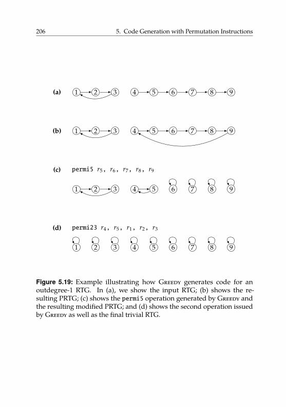
206 5. Code Generation with Permutation Instructions
(a) 1 2 3 4 5 6 7 8 9
(b) 1 2 3 4 5 6 7 8 9
(c)
1 2 3 4 5 6 7 8 9
permi5 r5, r6, r7, r8, r9
(d)
1 2 3 4 5 6 7 8 9
permi23 r4, r5, r1, r2, r3
Figure 5.19: Example illustrating how Greedy generates code for anoutdegree-1 RTG. In (a), we show the input RTG; (b) shows the re-sulting PRTG; (c) shows the permi5 operation generated by Greedy andthe resulting modified PRTG; and (d) shows the second operation issuedby Greedy as well as the final trivial RTG.
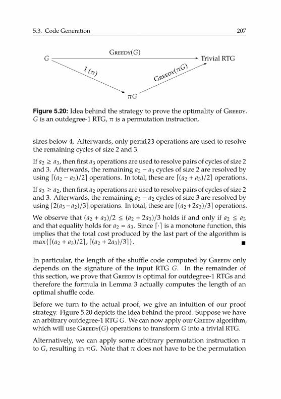
5.3. Code Generation 207
G Trivial RTG
πG
Greedy(G)
1 (π)Greedy(πG)
Figure 5.20: Idea behind the strategy to prove the optimality of Greedy.G is an outdegree-1 RTG, π is a permutation instruction.
sizes below 4. Afterwards, only permi23 operations are used to resolvethe remaining cycles of size 2 and 3.
If a2 ≥ a3, then first a3 operations are used to resolve pairs of cycles of size 2and 3. Afterwards, the remaining a2 − a3 cycles of size 2 are resolved byusing d(a2 − a3)/2e operations. In total, these are d(a2 + a3)/2e operations.
If a3 ≥ a2, then first a2 operations are used to resolve pairs of cycles of size 2and 3. Afterwards, the remaining a3 − a2 cycles of size 3 are resolved byusing d2(a3− a2)/3e operations. In total, these are d(a2+2a3)/3e operations.
We observe that (a2 + a3)/2 ≤ (a2 + 2a3)/3 holds if and only if a2 ≤ a3and that equality holds for a2 � a3. Since d·e is a monotone function, thisimplies that the total cost produced by the last part of the algorithm ismax{d(a2 + a3)/2e , d(a2 + 2a3)/3e}. �
In particular, the length of the shuffle code computed by Greedy onlydepends on the signature of the input RTG G. In the remainder ofthis section, we prove that Greedy is optimal for outdegree-1 RTGs andtherefore the formula in Lemma 3 actually computes the length of anoptimal shuffle code.
Before we turn to the actual proof, we give an intuition of our proofstrategy. Figure 5.20 depicts the idea behind the proof. Suppose we havean arbitrary outdegree-1 RTG G. We can now apply our Greedy algorithm,which will use Greedy(G) operations to transform G into a trivial RTG.
Alternatively, we can apply some arbitrary permutation instruction πto G, resulting in πG. Note that π does not have to be the permutation
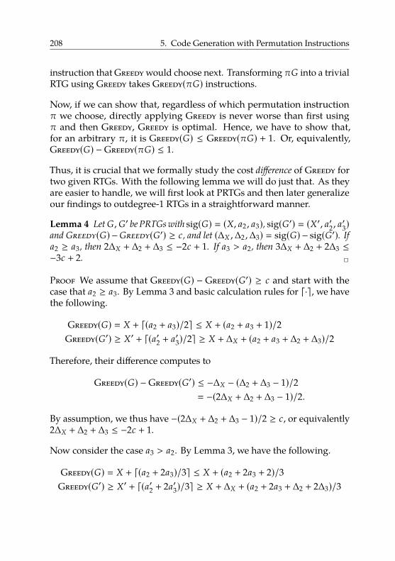
208 5. Code Generation with Permutation Instructions
instruction that Greedy would choose next. Transforming πG into a trivialRTG using Greedy takes Greedy(πG) instructions.
Now, if we can show that, regardless of which permutation instructionπ we choose, directly applying Greedy is never worse than first usingπ and then Greedy, Greedy is optimal. Hence, we have to show that,for an arbitrary π, it is Greedy(G) ≤ Greedy(πG) + 1. Or, equivalently,Greedy(G) −Greedy(πG) ≤ 1.
Thus, it is crucial that we formally study the cost difference of Greedy fortwo given RTGs. With the following lemma we will do just that. As theyare easier to handle, we will first look at PRTGs and then later generalizeour findings to outdegree-1 RTGs in a straightforward manner.
Lemma 4 Let G,G′ be PRTGs with sig(G) � (X, a2 , a3), sig(G′) � (X′, a′2 , a′3)and Greedy(G) −Greedy(G′) ≥ c, and let (∆X ,∆2 ,∆3) � sig(G) − sig(G′). If
a2 ≥ a3, then 2∆X + ∆2 + ∆3 ≤ −2c + 1. If a3 > a2, then 3∆X + ∆2 + 2∆3 ≤−3c + 2. 2
Proof We assume that Greedy(G) − Greedy(G′) ≥ c and start with thecase that a2 ≥ a3. By Lemma 3 and basic calculation rules for d·e, we havethe following.
Greedy(G) � X + d(a2 + a3)/2e ≤ X + (a2 + a3 + 1)/2Greedy(G′) ≥ X′ + d(a′2 + a′3)/2e ≥ X + ∆X + (a2 + a3 + ∆2 + ∆3)/2
Therefore, their difference computes to
Greedy(G) −Greedy(G′) ≤ −∆X − (∆2 + ∆3 − 1)/2� −(2∆X + ∆2 + ∆3 − 1)/2.
By assumption, we thus have −(2∆X + ∆2 + ∆3 − 1)/2 ≥ c, or equivalently2∆X + ∆2 + ∆3 ≤ −2c + 1.
Now consider the case a3 > a2. By Lemma 3, we have the following.
Greedy(G) � X + d(a2 + 2a3)/3e ≤ X + (a2 + 2a3 + 2)/3Greedy(G′) ≥ X′ + d(a′2 + 2a′3)/3e ≥ X + ∆X + (a2 + 2a3 + ∆2 + 2∆3)/3
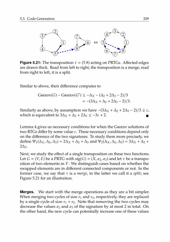
5.3. Code Generation 209
1
23
45
67
8⇔ 1
23
4
5
67
8
Figure 5.21: The transposition τ � (5 8) acting on PRTGs. Affected edgesare drawn thick. Read from left to right, the transposition is a merge; readfrom right to left, it is a split.
Similar to above, their difference computes to
Greedy(G) −Greedy(G′) ≤ −∆X − (∆2 + 2∆3 − 2)/3� −(3∆X + ∆2 + 2∆3 − 2)/3.
Similarly as above, by assumption we have −(3∆X + ∆2 + 2∆3 − 2)/3 ≥ c,which is equivalent to 3∆X + ∆2 + 2∆3 ≤ −3c + 2. �
Lemma 4 gives us necessary conditions for when the Greedy solutions oftwo RTGs differ by some value c. These necessary conditions depend onlyon the difference of the two signatures. To study them more precisely, wedefineΨ1(∆X ,∆2 ,∆3) � 2∆X + ∆2 + ∆3 andΨ2(∆X ,∆2 ,∆3) � 3∆X + ∆2 +2∆3.
Next, we study the effect of a single transposition on these two functions.Let G � (V, E) be a PRTG with sig(G) � (X, a2 , a3) and let τ be a transpo-sition of two elements in V . We distinguish cases based on whether theswapped elements are in different connected components or not. In theformer case, we say that τ is a merge, in the latter we call it a split; seeFigure 5.21 for an illustration.
Merges. We start with the merge operations as they are a bit simpler.When merging two cycles of size s1 and s2, respectively, they are replacedby a single cycle of size s1 + s2. Note that removing the two cycles maydecrease the values a2 and a3 of the signature by at most 2 in total. Onthe other hand, the new cycle can potentially increase one of these values
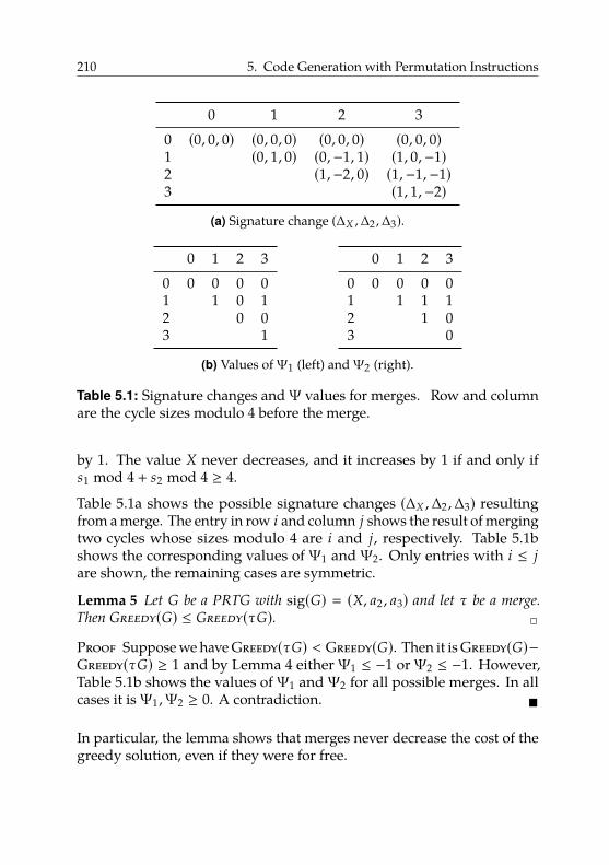
210 5. Code Generation with Permutation Instructions
0 1 2 30 (0, 0, 0) (0, 0, 0) (0, 0, 0) (0, 0, 0)1 (0, 1, 0) (0,−1, 1) (1, 0,−1)2 (1,−2, 0) (1,−1,−1)3 (1, 1,−2)
(a) Signature change (∆X ,∆2 ,∆3).
0 1 2 30 0 0 0 01 1 0 12 0 03 1
0 1 2 30 0 0 0 01 1 1 12 1 03 0
(b) Values ofΨ1 (left) andΨ2 (right).
Table 5.1: Signature changes andΨ values for merges. Row and columnare the cycle sizes modulo 4 before the merge.
by 1. The value X never decreases, and it increases by 1 if and only ifs1 mod 4 + s2 mod 4 ≥ 4.
Table 5.1a shows the possible signature changes (∆X ,∆2 ,∆3) resultingfrom a merge. The entry in row i and column j shows the result of mergingtwo cycles whose sizes modulo 4 are i and j, respectively. Table 5.1bshows the corresponding values of Ψ1 and Ψ2. Only entries with i ≤ jare shown, the remaining cases are symmetric.
Lemma 5 Let G be a PRTG with sig(G) � (X, a2 , a3) and let τ be a merge.
Then Greedy(G) ≤ Greedy(τG). 2
Proof Suppose we have Greedy(τG) < Greedy(G). Then it is Greedy(G)−Greedy(τG) ≥ 1 and by Lemma 4 eitherΨ1 ≤ −1 orΨ2 ≤ −1. However,Table 5.1b shows the values ofΨ1 andΨ2 for all possible merges. In allcases it isΨ1 ,Ψ2 ≥ 0. A contradiction. �
In particular, the lemma shows that merges never decrease the cost of thegreedy solution, even if they were for free.
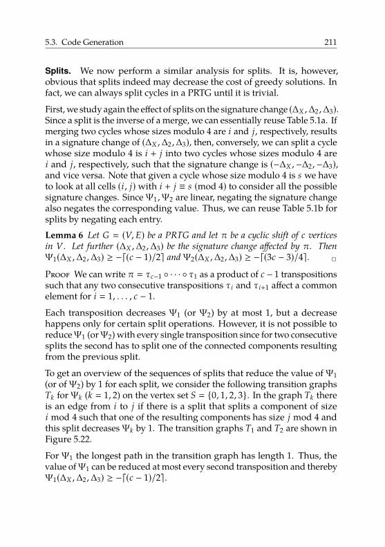
5.3. Code Generation 211
Splits. We now perform a similar analysis for splits. It is, however,obvious that splits indeed may decrease the cost of greedy solutions. Infact, we can always split cycles in a PRTG until it is trivial.
First, we study again the effect of splits on the signature change (∆X ,∆2 ,∆3).Since a split is the inverse of a merge, we can essentially reuse Table 5.1a. Ifmerging two cycles whose sizes modulo 4 are i and j, respectively, resultsin a signature change of (∆X ,∆2 ,∆3), then, conversely, we can split a cyclewhose size modulo 4 is i + j into two cycles whose sizes modulo 4 arei and j, respectively, such that the signature change is (−∆X ,−∆2 ,−∆3),and vice versa. Note that given a cycle whose size modulo 4 is s we haveto look at all cells (i , j)with i + j ≡ s (mod 4) to consider all the possiblesignature changes. SinceΨ1 ,Ψ2 are linear, negating the signature changealso negates the corresponding value. Thus, we can reuse Table 5.1b forsplits by negating each entry.
Lemma 6 Let G � (V, E) be a PRTG and let π be a cyclic shift of c vertices
in V . Let further (∆X ,∆2 ,∆3) be the signature change affected by π. Then
Ψ1(∆X ,∆2 ,∆3) ≥ −d(c − 1)/2e andΨ2(∆X ,∆2 ,∆3) ≥ −d(3c − 3)/4e. 2
Proof We can write π � τc−1 ◦ · · · ◦ τ1 as a product of c − 1 transpositionssuch that any two consecutive transpositions τi and τi+1 affect a commonelement for i � 1, . . . , c − 1.
Each transposition decreases Ψ1 (or Ψ2) by at most 1, but a decreasehappens only for certain split operations. However, it is not possible toreduceΨ1 (orΨ2) with every single transposition since for two consecutivesplits the second has to split one of the connected components resultingfrom the previous split.
To get an overview of the sequences of splits that reduce the value ofΨ1(or ofΨ2) by 1 for each split, we consider the following transition graphsTk forΨk (k � 1, 2) on the vertex set S � {0, 1, 2, 3}. In the graph Tk thereis an edge from i to j if there is a split that splits a component of sizei mod 4 such that one of the resulting components has size j mod 4 andthis split decreasesΨk by 1. The transition graphs T1 and T2 are shown inFigure 5.22.
For Ψ1 the longest path in the transition graph has length 1. Thus, thevalue ofΨ1 can be reduced at most every second transposition and therebyΨ1(∆X ,∆2 ,∆3) ≥ −d(c − 1)/2e.
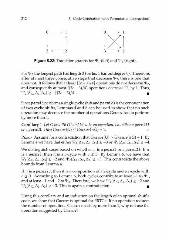
212 5. Code Generation with Permutation Instructions
0 1
23
0 1
23
Figure 5.22: Transition graphs forΨ1 (left) andΨ2 (right).
ForΨ2 the longest path has length 3 (vertex 1 has outdegree 0). Therefore,after at most three consecutive steps that decreaseΨ2, there is one thatdoes not. It follows that at least b(c − 1)/4c operations do not decreaseΨ2,and consequently at most d(3c − 3)/4e operations decreaseΨ2 by 1. Thus,Ψ2(∆X ,∆2 ,∆3) ≥ −d(3c − 3)/4e. �
Sincepermi5performs a single cyclic shift andpermi23 is the concatenationof two cyclic shifts, Lemmas 4 and 6 can be used to show that no suchoperation may decrease the number of operations Greedy has to performby more than 1.
Corollary 1 Let G be a PRTG and let π be an operation, i.e., either a permi23or a permi5. Then Greedy(G) ≤ Greedy(πG) + 1. 2
Proof Assume for a contradiction that Greedy(G) > Greedy(πG) − 1. ByLemma 4 we have that eitherΨ1(∆X ,∆2 ,∆3) ≤ −3 orΨ2(∆X ,∆2 ,∆3) ≤ −4.
We distinguish cases based on whether π is a permi5 or a permi23. If πis a permi5, then it is a c-cycle with c ≤ 5. By Lemma 6, we have thatΨ1(∆X ,∆2 ,∆3) ≥ −2 andΨ2(∆X ,∆2 ,∆3) ≥ −3. This contradicts the abovebounds from Lemma 4.
If π is a permi23, then it is a composition of a 2-cycle and a c-cycle withc ≤ 3. According to Lemma 6, both cycles contribute at least −1 to Ψ1,and at least −1 and −2 toΨ2. Therefore, we haveΨ1(∆X ,∆2 ,∆3) ≥ −2 andΨ2(∆X ,∆2 ,∆3) ≥ −3. This is again a contradiction. �
Using this corollary and an induction on the length of an optimal shufflecode, we show that Greedy is optimal for PRTGs. If no operation reducesthe number of operations Greedy needs by more than 1, why not use theoperation suggested by Greedy?
5.3. Code Generation 213
Theorem 1 Let G be a PRTG. An optimal shuffle code for G takes Greedy(G)operations. Algorithm Greedy computes an optimal shuffle code in linear time.2
Proof The proof is by induction on the overall length of an optimal shufflecode. Clearly, Greedy computes optimal shuffle codes for all instancesthat have a shuffle code of length 0.
Assume that G admits an optimal shuffle code of length k + 1. We showthat Greedy(G) � k + 1. First of all, note that Greedy(G) ≥ k + 1 as itcomputes a shuffle code of length Greedy(G). Let π1 , . . . , πk+1 be a shufflecode for G. Then obviously πk+1G admits an optimal shuffle code oflength k, and therefore Greedy(πk+1G) � k by our inductive assumption.Corollary 1 implies Greedy(G) ≤ Greedy(πk+1G)+1 � k+1; the inductionhypothesis is proved. Hence, algorithm Greedy indeed computes a correct,and thus optimal, shuffle code.
Also, it computes this optimal shuffle code in linear time, as we can see asfollows. The first step (completing directed paths into cycles) is clearlylinear. In each iteration of Greedy, one of the steps 2–5 is active and Greedygenerates one instruction. This instruction creates at least one loop. AsGreedy never touches vertices with loops again and stops when the RTGis trivial, the number of vertices n is an upper bound for the number ofiterations. As splitting a cycle only takes constant time, each iterationtakes constant time as well. Hence, Greedy runs in linear time. �
Moreover, since merge operations may not decrease the cost of Greedyand any PRTG that can be formed from the original outdegree-1 RTG G byinserting edges can be obtained from the PRTG G′ formed by Greedy anda sequence of merge operations, it follows that the length of an optimalshuffle for G is Greedy(G′).
Lemma 7 Let G be an outdegree-1 RTG and let G′ be the PRTG formed by
completing each directed path into a directed cycle. Then the length of an optimal
shuffle code of G is Greedy(G′). 2
Proof Assume π1 , . . . , πk is an optimal shuffle code for G. Of course,applying π � πk ◦ · · · ◦ π1 to G maps every value of G somewhere, thatis, π1 , . . . , πk is actually an optimal shuffle code for some instance G′′
that consists of a disjoint union of directed cycles and contains G as a
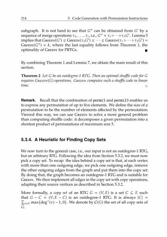
214 5. Code Generation with Permutation Instructions
subgraph. It is not hard to see that G′′ can be obtained from G′ by asequence of merge operations τ1 , . . . , τt , i.e., G′′ � τt ◦ · · ·◦τ1G′. Lemma 5implies that Greedy(G′) ≤ Greedy(τ1G′) ≤ · · · ≤ Greedy(τt ◦ · · · ◦ τ1G′) �Greedy(G′′) � k, where the last equality follows from Theorem 1, theoptimality of Greedy for PRTGs. �
By combining Theorem 1 and Lemma 7, we obtain the main result of thissection.
Theorem 2 Let G be an outdegree-1 RTG. Then an optimal shuffle code for Grequires Greedy(G) operations. Greedy computes such a shuffle code in linear
time. 2
Remark. Recall that the combination of permi5 and permi23 enables usto express any permutation of up to five elements. We define the size of apermutation to be the number of elements affected by the permutation.Viewed this way, we can use Greedy to solve a more general problemthan computing shuffle code: it decomposes a given permutation into ashortest product of permutations of maximum size 5.
5.3.4. A Heuristic for Finding Copy Sets
We now turn to the general case, i.e., our input is not an outdegree-1 RTG,but an arbitrary RTG. Following the idea from Section 5.3.2, we must nowpick a copy set. To recap: the idea behind a copy set is that, at each vertexwith more than one outgoing edge, we pick one outgoing edge, removethe other outgoing edges from the graph and put them into the copy set.By doing that, the graph becomes an outdegree-1 RTG and is suitable forGreedy. We then implement all edges in the copy set with copy operations,adapting their source vertices as described in Section 5.3.2.
More formally, a copy set of an RTG G � (V, E) is a set C ⊆ E suchthat G − C � (V, E − C) is an outdegree-1 RTG. It is always |C | �∑
v∈V max{deg+(v) − 1, 0}. We denote by C(G) the set of all copy sets ofG.
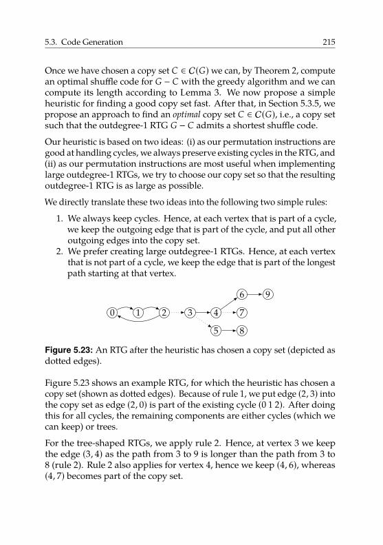
5.3. Code Generation 215
Once we have chosen a copy set C ∈ C(G)we can, by Theorem 2, computean optimal shuffle code for G − C with the greedy algorithm and we cancompute its length according to Lemma 3. We now propose a simpleheuristic for finding a good copy set fast. After that, in Section 5.3.5, wepropose an approach to find an optimal copy set C ∈ C(G), i.e., a copy setsuch that the outdegree-1 RTG G − C admits a shortest shuffle code.
Our heuristic is based on two ideas: (i) as our permutation instructions aregood at handling cycles, we always preserve existing cycles in the RTG, and(ii) as our permutation instructions are most useful when implementinglarge outdegree-1 RTGs, we try to choose our copy set so that the resultingoutdegree-1 RTG is as large as possible.
We directly translate these two ideas into the following two simple rules:
1. We always keep cycles. Hence, at each vertex that is part of a cycle,we keep the outgoing edge that is part of the cycle, and put all otheroutgoing edges into the copy set.
2. We prefer creating large outdegree-1 RTGs. Hence, at each vertexthat is not part of a cycle, we keep the edge that is part of the longestpath starting at that vertex.
0 1 2 3 4
5
6
7
8
9
Figure 5.23: An RTG after the heuristic has chosen a copy set (depicted asdotted edges).
Figure 5.23 shows an example RTG, for which the heuristic has chosen acopy set (shown as dotted edges). Because of rule 1, we put edge (2, 3) intothe copy set as edge (2, 0) is part of the existing cycle (0 1 2). After doingthis for all cycles, the remaining components are either cycles (which wecan keep) or trees.
For the tree-shaped RTGs, we apply rule 2. Hence, at vertex 3 we keepthe edge (3, 4) as the path from 3 to 9 is longer than the path from 3 to8 (rule 2). Rule 2 also applies for vertex 4, hence we keep (4, 6), whereas(4, 7) becomes part of the copy set.
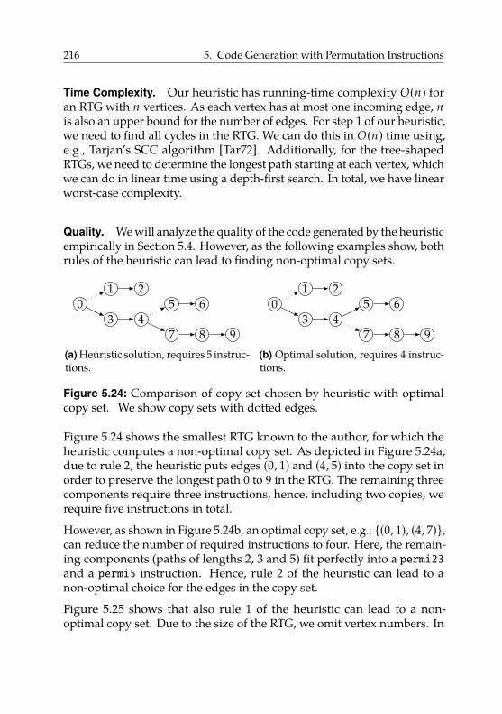
216 5. Code Generation with Permutation Instructions
Time Complexity. Our heuristic has running-time complexity O(n) foran RTG with n vertices. As each vertex has at most one incoming edge, nis also an upper bound for the number of edges. For step 1 of our heuristic,we need to find all cycles in the RTG. We can do this in O(n) time using,e.g., Tarjan’s SCC algorithm [Tar72]. Additionally, for the tree-shapedRTGs, we need to determine the longest path starting at each vertex, whichwe can do in linear time using a depth-first search. In total, we have linearworst-case complexity.
Quality. We will analyze the quality of the code generated by the heuristicempirically in Section 5.4. However, as the following examples show, bothrules of the heuristic can lead to finding non-optimal copy sets.
01 2
3 45 6
7 8 9(a) Heuristic solution, requires 5 instruc-tions.
01 2
3 45 6
7 8 9(b) Optimal solution, requires 4 instruc-tions.
Figure 5.24: Comparison of copy set chosen by heuristic with optimalcopy set. We show copy sets with dotted edges.
Figure 5.24 shows the smallest RTG known to the author, for which theheuristic computes a non-optimal copy set. As depicted in Figure 5.24a,due to rule 2, the heuristic puts edges (0, 1) and (4, 5) into the copy set inorder to preserve the longest path 0 to 9 in the RTG. The remaining threecomponents require three instructions, hence, including two copies, werequire five instructions in total.
However, as shown in Figure 5.24b, an optimal copy set, e.g., {(0, 1), (4, 7)},can reduce the number of required instructions to four. Here, the remain-ing components (paths of lengths 2, 3 and 5) fit perfectly into a permi23and a permi5 instruction. Hence, rule 2 of the heuristic can lead to anon-optimal choice for the edges in the copy set.
Figure 5.25 shows that also rule 1 of the heuristic can lead to a non-optimal copy set. Due to the size of the RTG, we omit vertex numbers. In
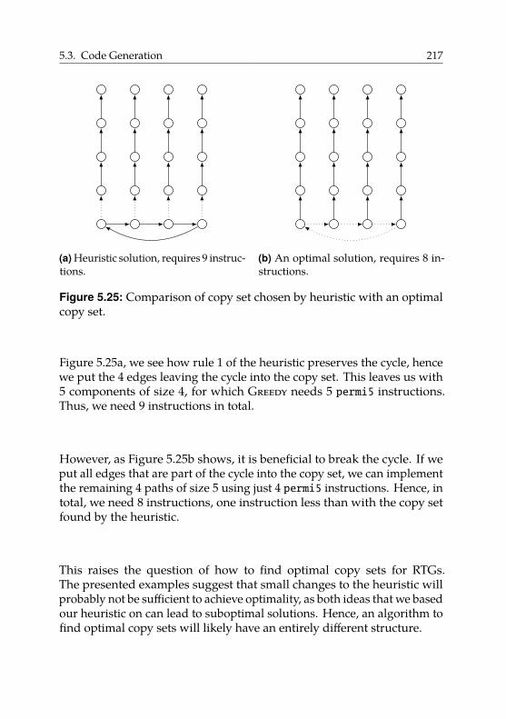
5.3. Code Generation 217
(a) Heuristic solution, requires 9 instruc-tions.
(b) An optimal solution, requires 8 in-structions.
Figure 5.25: Comparison of copy set chosen by heuristic with an optimalcopy set.
Figure 5.25a, we see how rule 1 of the heuristic preserves the cycle, hencewe put the 4 edges leaving the cycle into the copy set. This leaves us with5 components of size 4, for which Greedy needs 5 permi5 instructions.Thus, we need 9 instructions in total.
However, as Figure 5.25b shows, it is beneficial to break the cycle. If weput all edges that are part of the cycle into the copy set, we can implementthe remaining 4 paths of size 5 using just 4 permi5 instructions. Hence, intotal, we need 8 instructions, one instruction less than with the copy setfound by the heuristic.
This raises the question of how to find optimal copy sets for RTGs.The presented examples suggest that small changes to the heuristic willprobably not be sufficient to achieve optimality, as both ideas that we basedour heuristic on can lead to suboptimal solutions. Hence, an algorithm tofind optimal copy sets will likely have an entirely different structure.
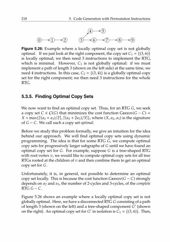
218 5. Code Generation with Permutation Instructions
0 1 2 3
4 5
6 7 8 9
Figure 5.26: Example where a locally optimal copy set is not globallyoptimal. If we just look at the right component, the copy set C1 � {(3, 6)}is locally optimal; we then need 3 instructions to implement the RTG,which is minimal. However, C1 is not globally optimal: if we mustimplement a path of length 3 (shown on the left side) at the same time, weneed 4 instructions. In this case, C2 � {(3, 4)} is a globally optimal copyset for the right component; we then need 3 instructions for the wholeRTG.
5.3.5. Finding Optimal Copy Sets
We now want to find an optimal copy set. Thus, for an RTG G, we seeka copy set C ∈ C(G) that minimizes the cost function Greedy(G − C) �X + max{d(a2 + a3)/2e , d(a2 + 2a3)/3e}, where (X, a2 , a3) is the signatureof G − C. We call such a copy set optimal.
Before we study this problem formally, we give an intuition for the ideabehind our approach. We will find optimal copy sets using dynamicprogramming. The idea is that for some RTG G, we compute optimalcopy sets for progressively larger subgraphs of G until we have found anoptimal copy set for G. For example, suppose G is a tree-shaped RTGwith root vertex v, we would like to compute optimal copy sets for all treeRTGs rooted at the children of v and then combine them to get an optimalcopy set for G.
Unfortunately, it is, in general, not possible to determine an optimalcopy set locally. This is because the cost function Greedy(G − C) stronglydepends on a2 and a3, the number of 2-cycles and 3-cycles, of the complete
RTG G − C.
Figure 5.26 shows an example where a locally optimal copy set is notglobally optimal. Here, we have a disconnected RTG G consisting of a pathof length 3 (shown on the left) and a tree-shaped component G′ (shownon the right). An optimal copy set for G′ in isolation is C1 � {(3, 6)}. Then,
5.3. Code Generation 219
G′ − C1 leaves a 4-cycle and a 3-cycle, so we need 3 instructions in total,which is minimal.
However, if we look at the complete RTG, it is better to choose C2 � {(3, 4)}as a copy set for G′. Locally, it does not make a difference: we wouldstill need 3 instructions for G′ alone. Yet, globally, we have a surplus of3-cycles because of the path of size 3. Hence, it is beneficial to choose C2as copy set for G′ to create a local surplus of 2-cycles. Globally, this resultsin an equal number of 2-cycles and 3-cycles, so Greedy can then match thepair and our overall costs are minimal.
Hence, we keep track of optimal copy sets for all possible combinations ofnumbers of remaining 2-cycles and 3-cycles. This guarantees that, at theend with a global view, we can choose the optimal copy set for the wholeRTG. In the following, we will formalize this idea.
Minimizing Greedy(G − C) is equivalent to minimizing the functionGreedy′ where we drop the rounding expressions:
Greedy′(G−C) � X+max{ a2 + a32 ,
a2 + 2a33 } �
{X +
a22 +
a32 if a2 ≥ a3
X +a23 +
2a33 if a2 < a3
To keep track of which case is used for evaluating Greedy′, we definediff(G − C) � a2 − a3 and compute for each of the two function parts andevery possible value d a copy set Cd with diff(G − Cd) � d that minimizesthat function.
More formally, we define cost1(G −C) � X +12 a2 +
12 a3 and cost2(G −C) �
X +13 a2 +
23 a3. We then seek two tables T1
G[·], T2G[·], such that T i
G[d] is thesmallest cost costi(G − C) that can be achieved with a copy set C ∈ C(G)with diff(G − C) � d.
We observe that T iG[d] � ∞ for d < −n and for d > n. The following
lemma shows how to compute the length of an optimal shuffle code fromthese two tables.
Lemma 8 Let G � (V, E) be an RTG. The length of an optimal shuffle code for Gis
∑v∈V max{deg+(v) − 1, 0} + min{mind≥0dT1
G[d]e ,mind<0dT2G[d]e}. 2
220 5. Code Generation with Permutation Instructions
Proof Let m �∑
v∈V max{deg+(v) − 1, 0}. Consider an optimal normal-ized shuffle code for G, which, according to Lemma 2, consists of a copyset C ⊆ E and a sequence of k permutation operations, i.e., the length ofthe shuffle code is m + k. Let (X, a2 , a3) denote the signature of G − C andlet d � a2 − a3.
If a2 ≥ a3, or equivalently d ≥ 0, then according to Theorem 2, we havek � Greedy(G−C) � X+ d(a2+ a3)/2e � dX+ (a2+ a3)/2e � dcost1(G−C)e,and therefore the length of the shuffle code is at most m + dT1
G[d]e.If a2 < a3, i.e., if d < 0, then we have k � Greedy(G − C) � X + d(a2 +
2a3)/3e � dX + (a2 + 2a3)/3e � dcost2(G − C)e, and therefore the length ofthe shuffle code is at most m + dT2
G[d]e.In either case the length of the shuffle code is bounded by the expressiongiven in the statement of the theorem.
Conversely, assume that the minimum of the expression is obtained forsome value T i
G[d].If d ≥ 0, there exists a copy set C such that sig(G − C) � (X, a2 , a3) andGreedy(G−C) � dcost1(G−C)e is at most dT1
G[d]e. Then, the shuffle codedefined by C and Greedy applied to G − C has length at most m + dT1
G[d]e.If d < 0, there exists a copy set C such that sig(G − C) � (X, a2 , a3) andGreedy(G−C) � dcost2(G−C)e is at most dT2
G[d]e. Then, the shuffle codedefined by C and Greedy applied to G−C has length at most m+ dT2
G[d]e.�
In the following, we show how to compute for an RTG G a table TG[·]with
TG[d] � minC∈C(G)
diff(G−C)�d
cost(G − C)
for an arbitrary cost function cost(G − C) � c(sig(G − C)), where c is alinear function. We do this in several steps depending on whether G isdisconnected, is a tree, or is connected and contains a cycle. Before wecontinue, we introduce several preliminaries to simplify the followingcalculations. We denote by Ps a directed path on s vertices.
Definition 3 A map f that assigns a value to an outdegree-1 RTG issignature-linear if there exists a linear function g : R3 → R such thatf (G) � g(sig(G)) for every outdegree-1 RTG G. For a signature-linearfunction f , ∆ f (s) � f (Ps+1) − f (Ps) is the correction term. 2
5.3. Code Generation 221
Note that both cost � c ◦ sig and diff � d ◦ sig with d(X, a2 , a3) � a2 − a3are signature-linear. The correction term ∆ f (s) describes the change of fwhen the size of one connected component is increased from s to s + 1.
Lemma 9 Let f be a signature-linear function. Then the following hold:
(i) f (G1 ∪ G2) � f (G1) + f (G2) for disjoint outdegree-1 RTGs G1 ,G2,
(ii) Let G � (V, E) be an outdegree-1 RTG and let v ∈ V with in-degree 0.
Denote by s the size of the connected component containing v and let
G+ � (V ∪ {u}, E ∪ {(u , v)}) where u is a new vertex. Then f (G+) �f (G) + ∆ f (s). 2
Proof For Statement (i) observe that sig(G1 ∪ G2) � sig(G1) + sig(G2);then the statement follows from the signature-linearity of f .
For Statement (ii) observe that by adding u, we replace a connectedcomponent of size s with one of size s + 1. Thus sig(G+) � sig(G) −sig(Ps) + sig(Ps+1). The statement follows from the signature-linearity off and the definition of ∆ f (s). �
Note that ∆ f (s) � ∆ f (s + 4) for all values of s and hence it suffices to knowthe size of the enlarged component modulo 4.
The main idea for computing table TG[·] by dynamic programming is todecompose G into smaller edge-disjoint subgraphs G � G1 ∪ · · · ∪Gk suchthat the copy sets of G can be constructed from copy sets for each of theGi .
We call such a decomposition proper partition if for every vertex v of Gthere exists an index i such that Gi contains all outgoing edges of v. LetG1 , . . . ,Gk be a proper partition of G and let Ci ⊆ C(Gi) for i � 1, . . . , k.We define C1 ⊗ · · · ⊗ Ck � {C1 ∪ · · · ∪ Ck | Ci ∈ Ci , i � 1, . . . , k}. It is nothard to see that C(G1 ∪ · · · ∪ Gk) � C(G1) ⊗ · · · ⊗ C(Gk).
5.3.5.1. Disconnected RTGs
We start with the case that G is disconnected and consists of connectedcomponents G1 , . . . ,Gk , which form a proper partition of G. Our intuition
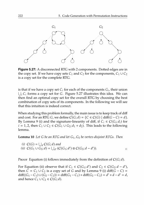
222 5. Code Generation with Permutation Instructions
x x
x x x
x x x
x x x
G1
x
x x x
x x x
x x
G2
Figure 5.27: A disconnected RTG with 2 components. Dotted edges are inthe copy set. If we have copy sets C1 and C2 for the components, C1 ∪ C2is a copy set for the complete RTG.
is that if we have a copy set Ci for each of the components Gi , their union⋃i Ci forms a copy set for G. Figure 5.27 illustrates this idea. We can
then find an optimal copy set for the overall RTG by choosing the bestcombination of copy sets of its components. In the following we will seethat this intuition is indeed correct.
When studying this problem formally, the main issue is to keep track of diffand cost. For an RTG G, we define C(G; d) � {C ∈ C(G) | diff(G−C) � d}.By Lemma 9 (i) and the signature-linearity of diff, if Ci ∈ C(Gi ; di) fori � 1, 2, then C1 ∪ C2 ∈ C(G1 ∪ G2; d1 + d2). This leads to the followinglemma.
Lemma 10 Let G be an RTG and let G1 ,G2 be vertex-disjoint RTGs. Then
(i) C(G) � ⋃d C(G; d) and
(ii) C(G1 ∪ G2; d) � ⋃d′ (C(G1; d′) ⊗ C(G2; d − d′)). 2
Proof Equation (i) follows immediately from the definition of C(G; d).
For Equation (ii) observe that if C1 ∈ C(G1; d′) and C2 ∈ C(G2; d − d′),then C � C1 ∪ C2 is a copy set of G and by Lemma 9 (i) diff(G − C) �diff((G1 −C1) ∪ (G2 −C2)) � diff(G1 −C1)+diff(G2 −C2) � d′+ d − d′ � d,and hence C1 ∪ C2 ∈ C(G; d).
5.3. Code Generation 223
Conversely, if C ∈ C(G; d), define Ci � C∩Ei where Ei is the edge set of Gifor i � 1, 2. Let d′ � diff(G1 − C1). As above, it follows from Lemma 9 (i)that d � diff(G −C) � diff(G1 −C1)+diff(G2 −C2) � d′ +diff(G −C), andhence diff(G − C) � d − d′. Thus C ∈ C(G1; d′) ⊗ C(G2; d − d′). �
By further exploiting the signature-linearity of cost, we also get cost((G1 ∪G2) − (C1 ∪ C2)) � cost(G1 − C1) + cost(G2 − C2), allowing us to computethe cost of copy sets formed by the union of copy sets of vertex-disjointgraphs.Lemma 11 Let G1 ,G2 be two vertex-disjoint RTGs and let G � G1 ∪G2. Then
TG[d] � mind′{TG1[d′] + TG2[d − d′]}. 2
Proof Applying the definition of TG[·] as well as Lemma 10 (ii) andLemma 9 (i) yields
TG[d] � minC∈C(G;d)
cost(G − C)
� minC∈⋃d′ (C(G1;d′)⊗C(G2;d−d′))
cost(G − C)
�mind′
{min
C∈C(G1;d′)⊗C(G2;d−d′)cost(G − C)
}�min
d′
{min
C1∈C(G1;d′)cost(G1 − C1) + min
C2∈C(G2;d−d′)cost(G2 − C2)
}�min
d′{TG1[d′] + TG2[d − d′]}. �
By iteratively applying Lemma 11, we compute TG[·] for a disconnectedRTG G with an arbitrary number of connected components.Lemma 12 Let G be an RTG with n vertices and connected components
G1 , . . . ,Gk . Given the tables TGi [·] for i � 1, . . . , k, the table TG[·] can be
computed in O(n2) time. 2
Proof Let ni denote the number of vertices of Gi . For two graphs H1 andH2 with h1 and h2 vertices, respectively, computing TH1∪H2[·] accordingto Lemma 11 takes time O(h1 · h2) and the table size is O(h1 + h2). Thus,iteratively combining the table for Gi+1 with the table for
⋃ij�1 G j takes time
O(∑k−1i�1 ni+1
∑ij�1 n j). It is
∑k−1i�1 ni+1
∑ij�1 n j ≤
∑k−1i�1 ni+1n � n
∑k−1i�1 ni+1 ≤
n2. Hence, the running time is O(n2). �
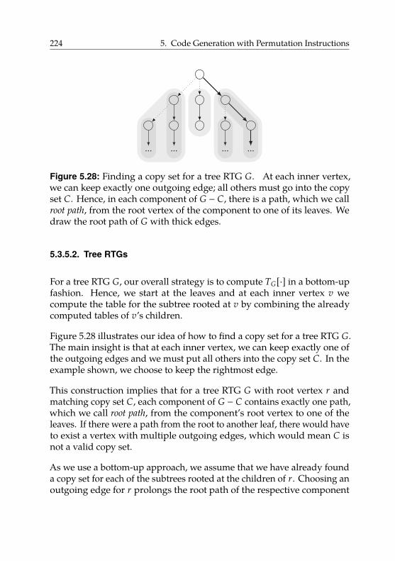
224 5. Code Generation with Permutation Instructions
x
x x x
x x x x x
... ... ... ...
Figure 5.28: Finding a copy set for a tree RTG G. At each inner vertex,we can keep exactly one outgoing edge; all others must go into the copyset C. Hence, in each component of G − C, there is a path, which we callroot path, from the root vertex of the component to one of its leaves. Wedraw the root path of G with thick edges.
5.3.5.2. Tree RTGs
For a tree RTG G, our overall strategy is to compute TG[·] in a bottom-upfashion. Hence, we start at the leaves and at each inner vertex v wecompute the table for the subtree rooted at v by combining the alreadycomputed tables of v’s children.
Figure 5.28 illustrates our idea of how to find a copy set for a tree RTG G.The main insight is that at each inner vertex, we can keep exactly one ofthe outgoing edges and we must put all others into the copy set C. In theexample shown, we choose to keep the rightmost edge.
This construction implies that for a tree RTG G with root vertex r andmatching copy set C, each component of G − C contains exactly one path,which we call root path, from the component’s root vertex to one of theleaves. If there were a path from the root to another leaf, there would haveto exist a vertex with multiple outgoing edges, which would mean C isnot a valid copy set.
As we use a bottom-up approach, we assume that we have already founda copy set for each of the subtrees rooted at the children of r. Choosing anoutgoing edge for r prolongs the root path of the respective component
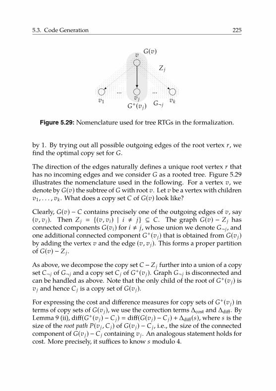
5.3. Code Generation 225
x
x ... x ... x
v
v jv1 vk
G(v)
G¬ jG+(v j)
Z j
Figure 5.29: Nomenclature used for tree RTGs in the formalization.
by 1. By trying out all possible outgoing edges of the root vertex r, wefind the optimal copy set for G.
The direction of the edges naturally defines a unique root vertex r thathas no incoming edges and we consider G as a rooted tree. Figure 5.29illustrates the nomenclature used in the following. For a vertex v, wedenote by G(v) the subtree of G with root v. Let v be a vertex with childrenv1 , . . . , vk . What does a copy set C of G(v) look like?
Clearly, G(v) − C contains precisely one of the outgoing edges of v, say(v , v j). Then Z j � {(v , vi) | i , j} ⊆ C. The graph G(v) − Z j hasconnected components G(vi) for i , j, whose union we denote G¬ j , andone additional connected component G+(v j) that is obtained from G(v j)by adding the vertex v and the edge (v , v j). This forms a proper partitionof G(v) − Z j .
As above, we decompose the copy set C −Z j further into a union of a copyset C¬ j of G¬ j and a copy set C j of G+(v j). Graph G¬ j is disconnected andcan be handled as above. Note that the only child of the root of G+(v j) isv j and hence C j is a copy set of G(v j).
For expressing the cost and difference measures for copy sets of G+(v j) interms of copy sets of G(v j), we use the correction terms ∆cost and ∆diff. ByLemma 9 (ii), diff(G+(v j) − C j) � diff(G(v j) − C j) +∆diff(s), where s is thesize of the root path P(v j , C j) of G(v j) − C j , i.e., the size of the connectedcomponent of G(v j) − C j containing v j . An analogous statement holds forcost. More precisely, it suffices to know s modulo 4.
226 5. Code Generation with Permutation Instructions
Therefore, we further decompose our copy sets as follows, which allowsus to formalize our discussion.
Definition 4 For a tree RTG G with root v and children v1 , . . . , vk , wedefine C(G; d , s) � {C ∈ C(G; d) | |P(v , C)| ≡ s (mod 4)}. We further de-compose these by C(G; d , s , j) � {C ∈ C(G; d , s) | (v , v j) < C}, accordingto which outgoing edge of the root is not in the copy set. 2
Lemma 13 Let G be a tree RTG with root v and children v1 , . . . , vk and for
a fixed vertex v j , 1 ≤ j ≤ k, let G+(v j) be the subgraph of G induced by
the vertices in G(v j) together with v. Let further G¬ j �⋃k
i�1,i, j G(vi) and
Z j � {(v , vi) | i , j}. Then
(i) C(G; d) � ⋃3s�0 C(G; d , s) and C(G; d , s) � ⋃k
j�1 C(G; d , s , j).(ii) C(G+(v j); d , s) � C(G(v j); d − ∆diff(s), s − 1).(iii) C(G; d , s , j) � ⋃
d′(C(G¬ j ; d′) ⊗ C(G+(v j); d − d′, s) ⊗ {Z j}
). 2
Proof Statements (i) follow immediately from the definitions of C(G; d , s)and C(G; d , s , j).
We continue with Statement (ii). Since v in G+(v j) has only one child v j ,the edge (v , v j) is not in any copy set of G+(v j). Therefore, the copy setsof C(G+(v j)) and C(G(v j)) are in one-to-one correspondence.
We need to understand how the partition into copy sets with differencemeasure d and root path length s (modulo 4) respects this bijection. Let sbe the root path size of G+(v j)−C for a copy set C ∈ C(G+(v j)). Obviously,|P(G(v j) − C)| � |P(G+(v j) − C)| − 1 � s − 1. Moreover, going fromG+(v j) −C to G(v j) −C replaces a connected component of size s with oneof size s−1. Therefore sig(G(v j)−C) � sig(G+(v j)−C)−sig(Ps)+sig(Ps+1).
By the signature-linearity of diff, we have diff(G(v j) − C) � diff(G+(v j) −C) − ∆diff(s). Note further that ∆diff(s) � ∆diff(s + 4) for every value ofs, and hence it suffices to know s mod 4. Overall, it follows that acopy set C ∈ C(G+(v j); d , s) is a copy set of G(v j) with difference measurediff(G+(v j)−C)−∆diff(s) and root path size modulo 4 being s−1. Thus C ∈C(G(v j), d−∆diff(s), s −1). And conversely C ∈ C(G(v j), d−∆diff(s), s −1)satisfies C ∈ C(G+(v j); d , s).
5.3. Code Generation 227
Next, we consider Statement (iii). First observe that the copy sets C of Gwhose root path starts with (v , v j) are exactly those copy sets of G thatcontain all edges in Z j . These sets correspond bijectively to copy sets ofG − Z j . Thus C(G; d , s , j) � C(G − Z j ; d , s) ⊗ {Z j}.
Observe that G − Z j � G¬ j ∪ G+(v j) is a proper partition of G − Z j .Furthermore, the root path of any copy set of this graph lies in G+(v j).Therefore Lemma 10 (ii) implies that C(G − Z j ; d , s) � ⋃
d′(C(G¬ j ; d′) ⊗(C(G(v j)+; d − d′, s). Combining this with the previously derived descrip-tion of C(G; d , s , j) yields Statement (iii). �
To make use of this decomposition of copy sets, we extend our ta-ble T with an additional parameter s to keep track of the size of theroot path modulo 4. We call the resulting table T̃. More formally,T̃v[d , s] � minC∈C(G(v);d ,s) cost(G(v) − C). It is not hard to see that TG[·]can be computed from T̃r[·, ·] for the root r of a tree RTG G.
Lemma 14 Let G be a tree RTG with root r. Then TG[d] � mins T̃r[d , s]. 2
Proof Using the definitions of TG[·] and T̃r[·, ·], we obtain
TG[d] � minC∈C(G;d)
cost(G−C) � mins∈{0,...,3}
minC∈C(G;d ,s)
cost(G−C) � mins∈{0,...,3}
T̃r[d , s].�
To compute T̃v[·, ·] in a bottom-up fashion, we exploit the decompositionsfrom Lemma 13 and the fact that we can update the cost function fromG(v j) − C j to G+(v j) − C j using the correction term ∆cost. The proof issimilar to that of Lemma 11 but more technical.
Lemma 15 Let G be a tree RTG, let v be a vertex of G with children v1 , . . . , vk ,
and let G(vi) � (Vi , Ei) for i � 1, . . . , k. Then with G¬ j � (V¬ j , E¬ j) �⋃ki�1,i, j G(vi) it is
T̃v[d , s] � minj∈{1,...,k}
mind′
TG¬ j [d′] + T̃v j [d − d′ − ∆diff(s), (s − 1)mod 4]
+ ∆cost(s).2
228 5. Code Generation with Permutation Instructions
Proof According to the definition of T̃v[d , s] and Lemma 13 (i), we findthat
T̃v[d , s] � minC∈C(G;d ,s)
cost(G − C) � minj
minC∈C(G;d ,s , j)
cost(G − C) (5.2)
Using Lemma 13 (iii) yields
minC∈C(G;d ,s , j)
cost(G − C) � mind′
minX∈C(G¬ j ;d′)
Y∈C(G+(v j );d−d′ ,s)
cost(G − X − Y − Z j). (5.3)
Note that G − Z j � G¬ j ∪ G+(v j). By Lemma 10, we have that forX ∈ C(G¬ j ; d′),Y ∈ C(G+(v j); d − d′, s), it is cost(G − X − Y − Z j) �cost(G¬ j ∪G+(v j) −X −Y) � cost(G¬ j −X)+ cost(G+(v j) −Y). Therefore,
minX∈C(G¬ j ;d′)
Y∈C(G+(v j );d−d′ ,s)
cost(G − X − Y − Z j)
� minX∈C(G¬ j ;d′)
cost(G¬ j − X) + minY∈C(G+(v j );d−d′ ,s)
cost(G+(v j) − Y).(5.4)
By definition minX∈C(G¬ j ;d′) cost(G¬ j −X) � TG¬ j [d′]. Furthermore, G+(v j)is a tree RTG whose root v has the single child v j . Hence, by Lemma 13 (ii)and Lemma 9 (ii), we find
minY∈C(G+(v j );d−d′ ,s)
cost(G+(v j) − Y)
� minY∈C(G(v j );d−d′−∆diff(s),s−1)
cost(G(v j) − Y) + ∆cost(s)
� T̃v j [d − d′ − ∆diff(s), s − 1] + ∆cost(s)
(5.5)
Combining Equations 5.2–5.5 yields the claim. �
For leaves v of a tree RTG G, T̃v[0, 1] � 0 and all other entries are∞. Wecompute TG[·] by iteratively applying Lemma 15 in a bottom-up fashion,using Lemma 14 to compute T[·] from T̃[·, ·] in linear time when needed.
Lemma 16 Let G � (V, E) be a tree RTG with n vertices and root r. The tables
T̃r[·, ·] and TG[·] can be computed in O(n3) time. 2
Proof First observe that given T̃v[·, ·] for v ∈ V , table TG(v)[·] can becomputed in linear time according to Lemma 14. In particular, TG[·] canbe computed from T̃r[·, ·] in linear time.
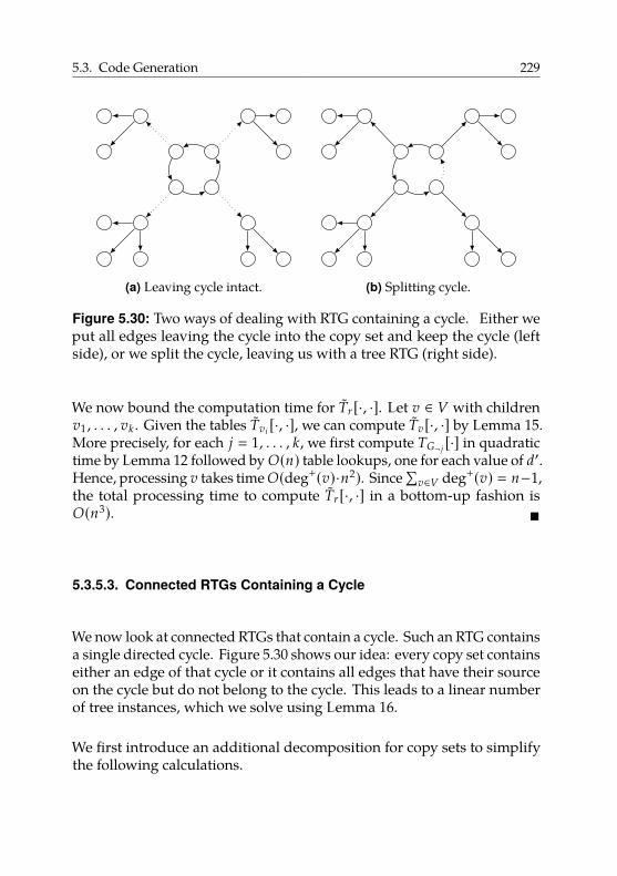
5.3. Code Generation 229
x x x x
x x x x
x x
x x x
x x x x
(a) Leaving cycle intact.
x x x x
x x x x
x x
x x x
x x x x
(b) Splitting cycle.
Figure 5.30: Two ways of dealing with RTG containing a cycle. Either weput all edges leaving the cycle into the copy set and keep the cycle (leftside), or we split the cycle, leaving us with a tree RTG (right side).
We now bound the computation time for T̃r[·, ·]. Let v ∈ V with childrenv1 , . . . , vk . Given the tables T̃vi [·, ·], we can compute T̃v[·, ·] by Lemma 15.More precisely, for each j � 1, . . . , k, we first compute TG¬ j [·] in quadratictime by Lemma 12 followed by O(n) table lookups, one for each value of d′.Hence, processing v takes time O(deg+(v)·n2). Since
∑v∈V deg+(v) � n−1,
the total processing time to compute T̃r[·, ·] in a bottom-up fashion isO(n3). �
5.3.5.3. Connected RTGs Containing a Cycle
We now look at connected RTGs that contain a cycle. Such an RTG containsa single directed cycle. Figure 5.30 shows our idea: every copy set containseither an edge of that cycle or it contains all edges that have their sourceon the cycle but do not belong to the cycle. This leads to a linear numberof tree instances, which we solve using Lemma 16.
We first introduce an additional decomposition for copy sets to simplifythe following calculations.
230 5. Code Generation with Permutation Instructions
Lemma 17 Let G � (V, E) be a connected RTG containing a directed cycle Kand let e1 , . . . , ek denote the edges of K whose source has out-degree at least 2.
Let further O � {(u , v) ∈ E | u ∈ K, (u , v) < K}. Then
C(G; d) � C(G − O; d) ⊗ {O} ∪k⋃
i�1C(G − ei ; d) ⊗ {{ei}}. 2
Proof Every copy set C ∈ C(G; d) contains either some edge of K or itcontains all edges in O. Note that edges of K that are not among e1 , . . . , ekare not contained in any copy set. Thus, in the former case, ei ∈ C forsome i ∈ {1, . . . , k} and hence C ∈ C(G − ei ; d) ⊗ {{ei}}. In the latter caseC \ O is a copy set of G − O, hence C ∈ C(G − O; d) ⊗ {O}. Conversely,any copy set in C(G − O; d) ⊗ {O} forms a copy set of G and also everycopy set in C(G − ei ; d) ⊗ {{ei}} for any value of i forms a copy set of G.This finishes the proof. �
As before, this decomposition can be used to efficiently compute TG[·]from the tables of smaller subgraphs of a connected RTG G containing acycle.
Lemma 18 Let G � (V, E) be a connected RTG containing a directed cycle Kand let e1 , . . . , ek denote the edges of K whose source has out-degree at least 2.
Let further O � {(u , v) ∈ E | u ∈ K, (u , v) < K}. Then
TG[d] � min{TG−O[d],
kmini�1
TG−ei [d]}.
2
Proof Using the definition of TG[·] and Lemma 17, we find that
TG[d] � minC∈C(G;d)
cost(G−C) � minC∈(C(G−O;d)⊗{O})∪⋃k
i�1(C(G−ei ;d)⊗{{ei }})cost(G−C).
As we minimize cost over a union of sets, we can minimize it over the setsindividually and then take the minimum of the results. Hence, we findthat
minC∈C(G−O;d)⊗{O}
cost(G − C) � minC∈C(G−O;d)
cost(G − O − C) � TG−O[d]
5.3. Code Generation 231
and
minC∈C(G−ei ;d)⊗{{ei }}
cost(G − C) � minC∈C(G−ei ;d)
cost(G − ei − C) � TG−ei [d],
which together yield the claim. �
Lemma 19 Let G � (V, E) be a connected RTG containing a directed cycle. The
table TG[·] can be computed in O(n4) time. 2
Proof Let e1 , . . . , ek be the edges of the cycle K. First, observe that G − eiis a tree for i � 1, . . . , k. Hence, we can compute each table TG−ei [·] inO(n3) time by Lemma 16. Thus, computing all these tables takes O(n4)time.
Second, let O � {(u , v) ∈ E | u ∈ K, (u , v) < K}. The graph G − O is thedisjoint union of the cycle K and several tree RTGs G1 , . . . ,Gt . The tableTK[·] has only one finite entry and can be computed in constant time. Thetables TGi [·] can be computed in O(n3) time. Using Lemma 12, we thencompute TG−O[·] in quadratic time.
With these tables available, we can compute TG[·] according to Lemma 18.This takes O(n2) time. The overall running time is thus O(n4). �
5.3.5.4. Putting Things Together
To compute TG[·] for an arbitrary RTG G, we first compute TK[·] for eachconnected component K of G using Lemmas 16 and 19. Then, we computeTG[·] using Lemma 12 and the length of an optimal shuffle code usingLemma 8. To actually compute the shuffle code, we augment the dynamicprogram computing TG[·] such that an optimal copy set C can be foundby backtracking in the tables. An optimal shuffle code is then found byapplying Greedy to G − C and adding one copy operation for each edge inC.
Theorem 3 Given an RTG G, an optimal shuffle code can be computed in O(n4)time. 2
232 5. Code Generation with Permutation Instructions
Proof We compute all tables TC[·] where C is a connected componentof G in O(n4) time using Lemmas 16 and 19. Using Lemma 12, we thencompute TG[·] in O(n2) time. From this, we can compute the length of anoptimal shuffle code by Lemma 8.
In fact, it is not difficult to modify the dynamic program in a way that, givenan entry TG[d], a corresponding copy set C of G with cost(G − C) � TG[d]can be computed by backtracking in the tables. Hence, to compute anoptimal shuffle code for G, we first compute an optimal copy set Copt of Gin O(n4) time. Then, we compute an optimal shuffle code π1 , . . . , πk forG − Copt using Greedy, which takes linear time according to Theorem 2.
Let π � πk◦. . .◦π1. For each edge (u , v) ∈ Copt, we define a correspondingcopy operation π(u) → v. Let c1 , . . . , ct be these copy operations inarbitrary order. Then the sequence S � π1 , . . . , πk , c1 , . . . , ct is an optimalshuffle code.
This can be seen as follows. First, by Lemma 8, the length of S is minimal.It remains to show that S is indeed a shuffle code for G. This is clearlytrue, as it first shuffles the values in the registers so that a subset of thevalues is in the correct position and then uses copy operations to transferthe remaining values to their destinations. �
5.3.6. Related Work
From a practical point of view, our work is related to work that studiesparallel copies in the context of SSA-based register allocation. Insteadof implementing the parallel copies at the place where the φ-function is(usually the end of the preceding basic blocks), Bouchez et al. [Bou+10]propose a technique to move the parallel copy so that its implementationinvolves fewer copies. Brandner et al. [BC13] further improve upon thistechnique using data dependence graphs. Rideau et al. [RSL08] give aformal proof for the implementation correctness of parallel copies.
From a theoretical point of view, the most closely related work studies thecase where the input RTG consists of a union of disjoint directed cycles,which can be interpreted as a permutation π. Then, no copy operationsare necessary for an optimal shuffle code and hence the problem of finding
5.3. Code Generation 233
an optimal shuffle code using permi23 and permi5 is equivalent to writingπ as a shortest product of permutations of maximum size 5, where apermutation of n elements has size k if it fixes n − k elements.
There has been work on writing a permutation as a product of permutationsthat satisfy certain restrictions. The factorization problem on permutationgroups from computational group theory [Ser03] is the task of writingan element g of a permutation group as a product of given generatorsS. Hence, an algorithm for solving the factorization problem could beapplied in our context by using all possible permutations of size 5 or lessas the set S. However, the algorithms do not guarantee minimality of theproduct. For the case that S consists of all permutations that reverse acontiguous subsequence of the elements, known as the pancake sortingproblem, it has been shown that computing a factoring of minimum sizeis NP-complete [Cap97].
Farnoud and Milenkovic [FM12] consider a weighted version of factoringa permutation into transpositions. They present a polynomial constant-factor approximation algorithm for factoring a given permutation intotranspositions where transpositions have arbitrary non-negative costs. Inour problem, we cannot assign costs to an individual transposition as itscost is context-dependent, e.g., four transpositions whose product is acycle require one operation, whereas four arbitrary transpositions mayrequire two.
Stanley [Sta81] investigates the number of ways a permutation π ∈ Sncan be expressed as a product of k n-cycles. Similarly, [Str96] presents anoverview of work on the problem of determining the number of ways agiven permutation can be written as the product of transpositions such thatthe transpositions generate the full symmetric group, and such that thenumber of factors is as small as possible. However, we are not interestedin the number of ways a given permutation can be expressed as productsof transpositions or cycles. Instead, we want to efficiently find a specificproduct minimizing a special cost measure.

234 5. Code Generation with Permutation Instructions
5.4. Evaluation
Our experimental evaluation consists of four parts. First, we analyzethe structure of the RTGs in our test inputs. Second, we compare thequality of our two proposed code-generation approaches relative to eachother by comparing the number of instructions generated for the RTGsin our test inputs. Moreover, we investigate the running times of ourcode-generation approaches. Third, and most importantly, we determinethe benefit of using permutation instructions. We generate code for ourtest inputs and then measure precise dynamic instruction counts of theproduced executables. We then validate these numbers by measuring theactual running time of the same executables on our hardware prototypepresented in Section 5.2. In both cases, we compare an executable usingpermutation instructions to an executable that uses the regular instructionset. Finally, we discuss the impact of permutation reversion and presentan area and frequency overhead analysis for the hardware prototypeimplementation.
5.4.1. Setup
We have implemented the code generation strategies from Sections 5.3.4and 5.3.5 in libFirm [BBZ11]44. This compiler features a mature SPARCbackend and multiple completely SSA-based register allocators and copy-coalescing schemes. As compiler input, we used the test programscontained in the integer part CINT2000 of the SPEC CPU2000 benchmarksuite [Hen00]. We excluded the program 252.eon from the measurementsbecause the frontend45 does not support C++ code.
We performed all compile-time measurements on an Intel Core i7-3770workstation with 3.4 GHz and 16 GiB RAM using Linux kernel 3.5. Tomeasure the quality of the generated code, we modified the CPU emulator
44For libFirm, we used Git revision 88c319e982d42c57b06ccecfee20b5286aafe3ec.For the comparison with the optimal code-generation approach, we used Git revision778065d2dde3b7c20d4f7a25485f2d63068f6f1b of libFirm.
45We used Git revision 7c6cd91cc5a2bef0b9f4555250c1266cf07d0da5 for the C frontendcparser.
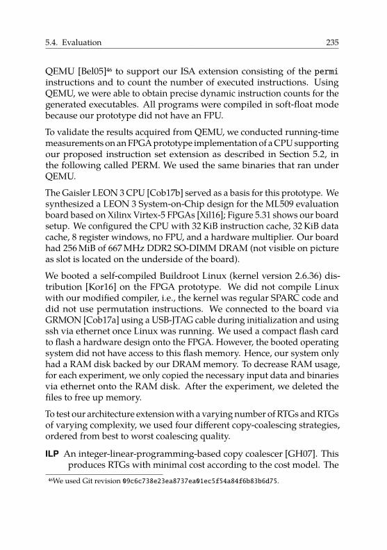
5.4. Evaluation 235
QEMU [Bel05]46 to support our ISA extension consisting of the permiinstructions and to count the number of executed instructions. UsingQEMU, we were able to obtain precise dynamic instruction counts for thegenerated executables. All programs were compiled in soft-float modebecause our prototype did not have an FPU.
To validate the results acquired from QEMU, we conducted running-timemeasurements on an FPGA prototype implementation of a CPU supportingour proposed instruction set extension as described in Section 5.2, inthe following called PERM. We used the same binaries that ran underQEMU.
The Gaisler LEON 3 CPU [Cob17b] served as a basis for this prototype. Wesynthesized a LEON 3 System-on-Chip design for the ML509 evaluationboard based on Xilinx Virtex-5 FPGAs [Xil16]; Figure 5.31 shows our boardsetup. We configured the CPU with 32 KiB instruction cache, 32 KiB datacache, 8 register windows, no FPU, and a hardware multiplier. Our boardhad 256 MiB of 667 MHz DDR2 SO-DIMM DRAM (not visible on pictureas slot is located on the underside of the board).
We booted a self-compiled Buildroot Linux (kernel version 2.6.36) dis-tribution [Kor16] on the FPGA prototype. We did not compile Linuxwith our modified compiler, i.e., the kernel was regular SPARC code anddid not use permutation instructions. We connected to the board viaGRMON [Cob17a] using a USB-JTAG cable during initialization and usingssh via ethernet once Linux was running. We used a compact flash cardto flash a hardware design onto the FPGA. However, the booted operatingsystem did not have access to this flash memory. Hence, our system onlyhad a RAM disk backed by our DRAM memory. To decrease RAM usage,for each experiment, we only copied the necessary input data and binariesvia ethernet onto the RAM disk. After the experiment, we deleted thefiles to free up memory.
To test our architecture extension with a varying number of RTGs and RTGsof varying complexity, we used four different copy-coalescing strategies,ordered from best to worst coalescing quality.
ILP An integer-linear-programming-based copy coalescer [GH07]. Thisproduces RTGs with minimal cost according to the cost model. The
46We used Git revision 09c6c738e23ea8737ea01ec5f54a84f6b83b6d75.
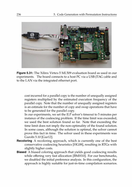
236 5. Code Generation with Permutation Instructions
Figure 5.31: The Xilinx Virtex-5 ML509 evaluation board as used in ourexperiments. The board connects to a host PC via a USB-JTAG cable andto the LAN via the integrated ethernet port.
cost incurred for a parallel copy is the number of unequally assignedregisters multiplied by the estimated execution frequency of theparallel copy. Note that the number of unequally assigned registersis an estimate for the number of copy and swap operations that haveto be generated for the parallel copy.In our experiments, we set the ILP solver’s timeout to 5 minutes perinstance of the coalescing problem. If the time limit was exceeded,we used the best solution found so far. Note that exceeding thetime limit does not imply the non-optimality of the found solution.In some cases, although the solution is optimal, the solver cannotprove this fact in time. The solver used in these experiments wasGurobi 5.10 [Gur12].
Recoloring A recoloring approach, which is currently one of the bestconservative coalescing heuristics [HG08], resulting in RTGs withslightly higher costs.
Biased A biased coloring approach that yields good coalescing resultswhile offering very fast allocation [BMH10]. For our benchmarks,we disabled the initial preference analysis. In this configuration, theapproach is highly suitable for just-in-time compilation scenarios.
5.4. Evaluation 237
The generated code contains RTGs of higher cost than with therecoloring approach.
Naive This approach does not perform any sophisticated copy coalescingat all. Except for trying to avoid copy instructions because of registerconstraints, no effort is made to coalesce copies. In general, thisresults in RTGs with high costs.
For each coalescing strategy, we inspected the properties of typical RTGsoccurring in our test programs to estimate the potential benefit of usingpermutation instructions. Furthermore, for each of the four coalescingstrategies, we tested three compiler configurations: one that generatedpermutation instructions using the heuristic code-generation strategypresented in Section 5.3.4, one that used the optimal strategy from Sec-tion 5.3.5, and one that emitted regular SPARC code. In the following, wefocused on two configurations: the one using heuristic code generationand the one emitting SPARC code. For each of the resulting eight compilerconfigurations, we measured the compilation time and the quality of thegenerated code.
We mentioned parallel-copy-motion techniques in Section 5.3.6. In libFirm,we use a faster but less sophisticated technique, which leaves more parallelcopies in the code as it only works on a single basic block. Essentially, ittries to hoist parallel copies inside a block to a location with less registerpressure. However, this technique is not a contribution of this dissertation.It was enabled during all measurements.
5.4.2. Register-Transfer-Graph Properties
The number and properties of RTGs directly depend on the used coalescingstrategy, which tries to minimize the cost of RTGs according to a cost model.For ease of presentation, we will use the number of RTGs and their averagesize as an approximation for the costs assigned to the RTGs. In general,the number and sizes of RTGs and their costs are highly correlated.
For each coalescing strategy, we analyzed the number and average size ofRTGs over all programs of the CINT2000 benchmark suite. Moreover, wechecked what percentage of RTGs do not duplicate any values, i.e., can
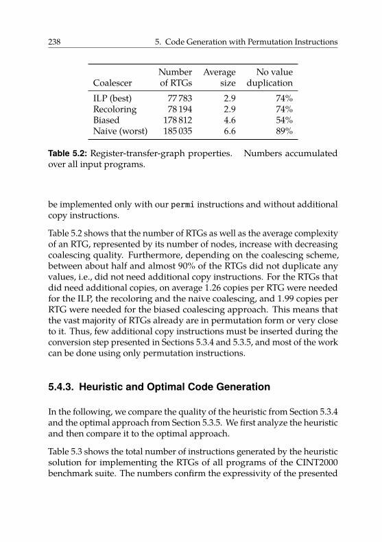
238 5. Code Generation with Permutation Instructions
Number Average No valueCoalescer of RTGs size duplicationILP (best) 77 783 2.9 74%Recoloring 78 194 2.9 74%Biased 178 812 4.6 54%Naive (worst) 185 035 6.6 89%
Table 5.2: Register-transfer-graph properties. Numbers accumulatedover all input programs.
be implemented only with our permi instructions and without additionalcopy instructions.
Table 5.2 shows that the number of RTGs as well as the average complexityof an RTG, represented by its number of nodes, increase with decreasingcoalescing quality. Furthermore, depending on the coalescing scheme,between about half and almost 90% of the RTGs did not duplicate anyvalues, i.e., did not need additional copy instructions. For the RTGs thatdid need additional copies, on average 1.26 copies per RTG were neededfor the ILP, the recoloring and the naive coalescing, and 1.99 copies perRTG were needed for the biased coalescing approach. This means thatthe vast majority of RTGs already are in permutation form or very closeto it. Thus, few additional copy instructions must be inserted during theconversion step presented in Sections 5.3.4 and 5.3.5, and most of the workcan be done using only permutation instructions.
5.4.3. Heuristic and Optimal Code Generation
In the following, we compare the quality of the heuristic from Section 5.3.4and the optimal approach from Section 5.3.5. We first analyze the heuristicand then compare it to the optimal approach.
Table 5.3 shows the total number of instructions generated by the heuristicsolution for implementing the RTGs of all programs of the CINT2000benchmark suite. The numbers confirm the expressivity of the presented
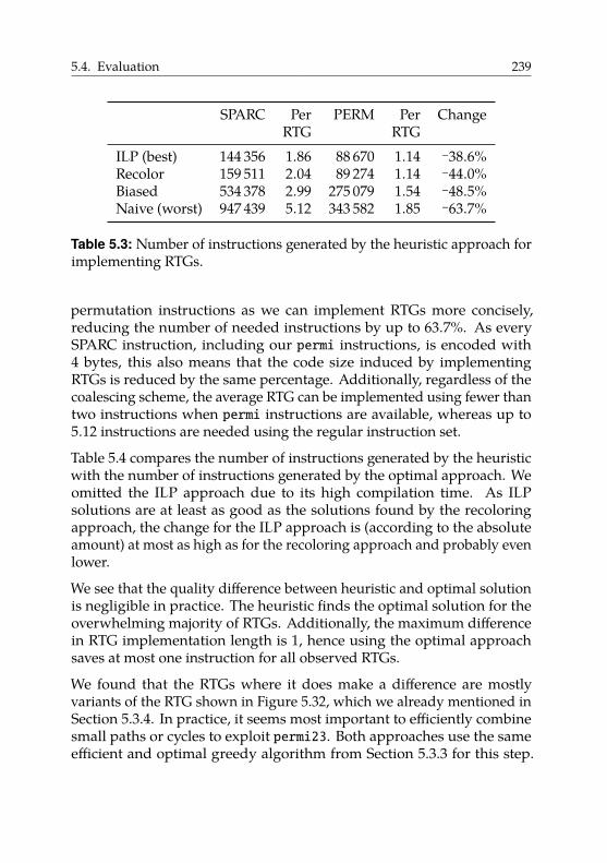
5.4. Evaluation 239
SPARC Per PERM Per ChangeRTG RTG
ILP (best) 144 356 1.86 88 670 1.14 −38.6%Recolor 159 511 2.04 89 274 1.14 −44.0%Biased 534 378 2.99 275 079 1.54 −48.5%Naive (worst) 947 439 5.12 343 582 1.85 −63.7%
Table 5.3: Number of instructions generated by the heuristic approach forimplementing RTGs.
permutation instructions as we can implement RTGs more concisely,reducing the number of needed instructions by up to 63.7%. As everySPARC instruction, including our permi instructions, is encoded with4 bytes, this also means that the code size induced by implementingRTGs is reduced by the same percentage. Additionally, regardless of thecoalescing scheme, the average RTG can be implemented using fewer thantwo instructions when permi instructions are available, whereas up to5.12 instructions are needed using the regular instruction set.
Table 5.4 compares the number of instructions generated by the heuristicwith the number of instructions generated by the optimal approach. Weomitted the ILP approach due to its high compilation time. As ILPsolutions are at least as good as the solutions found by the recoloringapproach, the change for the ILP approach is (according to the absoluteamount) at most as high as for the recoloring approach and probably evenlower.
We see that the quality difference between heuristic and optimal solutionis negligible in practice. The heuristic finds the optimal solution for theoverwhelming majority of RTGs. Additionally, the maximum differencein RTG implementation length is 1, hence using the optimal approachsaves at most one instruction for all observed RTGs.
We found that the RTGs where it does make a difference are mostlyvariants of the RTG shown in Figure 5.32, which we already mentioned inSection 5.3.4. In practice, it seems most important to efficiently combinesmall paths or cycles to exploit permi23. Both approaches use the sameefficient and optimal greedy algorithm from Section 5.3.3 for this step.
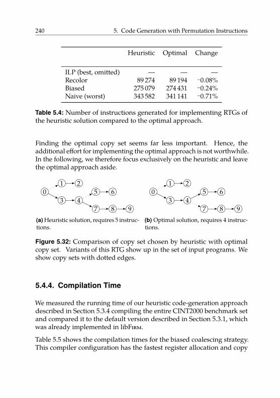
240 5. Code Generation with Permutation Instructions
Heuristic Optimal Change
ILP (best, omitted) — — —Recolor 89 274 89 194 −0.08%Biased 275 079 274 431 −0.24%Naive (worst) 343 582 341 141 −0.71%
Table 5.4: Number of instructions generated for implementing RTGs ofthe heuristic solution compared to the optimal approach.
Finding the optimal copy set seems far less important. Hence, theadditional effort for implementing the optimal approach is not worthwhile.In the following, we therefore focus exclusively on the heuristic and leavethe optimal approach aside.
01 2
3 45 6
7 8 9(a) Heuristic solution, requires 5 instruc-tions.
01 2
3 45 6
7 8 9(b) Optimal solution, requires 4 instruc-tions.
Figure 5.32: Comparison of copy set chosen by heuristic with optimalcopy set. Variants of this RTG show up in the set of input programs. Weshow copy sets with dotted edges.
5.4.4. Compilation Time
We measured the running time of our heuristic code-generation approachdescribed in Section 5.3.4 compiling the entire CINT2000 benchmark setand compared it to the default version described in Section 5.3.1, whichwas already implemented in libFirm.
Table 5.5 shows the compilation times for the biased coalescing strategy.This compiler configuration has the fastest register allocation and copy
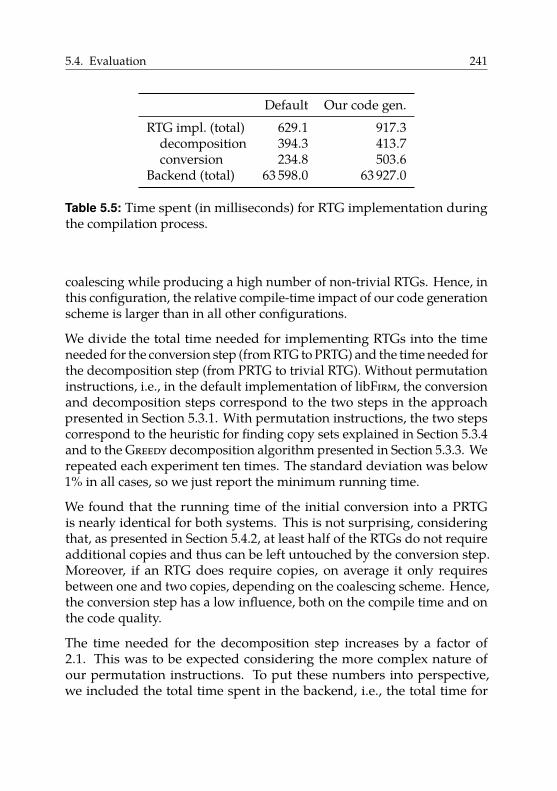
5.4. Evaluation 241
Default Our code gen.RTG impl. (total) 629.1 917.3
decomposition 394.3 413.7conversion 234.8 503.6
Backend (total) 63 598.0 63 927.0
Table 5.5: Time spent (in milliseconds) for RTG implementation duringthe compilation process.
coalescing while producing a high number of non-trivial RTGs. Hence, inthis configuration, the relative compile-time impact of our code generationscheme is larger than in all other configurations.
We divide the total time needed for implementing RTGs into the timeneeded for the conversion step (from RTG to PRTG) and the time needed forthe decomposition step (from PRTG to trivial RTG). Without permutationinstructions, i.e., in the default implementation of libFirm, the conversionand decomposition steps correspond to the two steps in the approachpresented in Section 5.3.1. With permutation instructions, the two stepscorrespond to the heuristic for finding copy sets explained in Section 5.3.4and to the Greedy decomposition algorithm presented in Section 5.3.3. Werepeated each experiment ten times. The standard deviation was below1% in all cases, so we just report the minimum running time.
We found that the running time of the initial conversion into a PRTGis nearly identical for both systems. This is not surprising, consideringthat, as presented in Section 5.4.2, at least half of the RTGs do not requireadditional copies and thus can be left untouched by the conversion step.Moreover, if an RTG does require copies, on average it only requiresbetween one and two copies, depending on the coalescing scheme. Hence,the conversion step has a low influence, both on the compile time and onthe code quality.
The time needed for the decomposition step increases by a factor of2.1. This was to be expected considering the more complex nature ofour permutation instructions. To put these numbers into perspective,we included the total time spent in the backend, i.e., the total time for
242 5. Code Generation with Permutation Instructions
code selection, instruction scheduling, register allocation and emittingof assembly code. The total time spent in the backend increases by 0.5%,so the presented code generation approach does not cause significantoverhead.
5.4.5. Code Quality
We evaluated the quality of the generated code using two experiments:
1. We performed a full run of the CINT2000 benchmark suite, collectingprecise dynamic instruction counts using our modified QEMUversion.
2. We validated these results by measuring the running times of thesame executables on our FPGA prototype.
Table 5.6 shows the absolute number of executed instructions during afull CINT2000 run. We used the full input datasets provided by SPEC.The table lists the instruction count of the version using permutationinstructions and the regular SPARC version, as well as the matchinginstruction-count change. The results are shown separately for each of thefour coalescing schemes.
As expected from the numbers presented in Section 5.4.2, the benefitof using permutation instructions directly depends on the quality ofcoalescing: the worse the coalescing, the higher the benefit of usingpermutation instructions. However, regardless of the coalescing schemeused, every program profited from the use of permutation instructions.For the biased coalescing scheme, suitable for just-in-time compilationscenarios, the number of executed instructions is reduced by up to 5.1%.Even using the optimal coalescing solution, permutation instructions canreduce the instruction count by up to 1.9%.
Interestingly, the use of permutation instructions can often more thancompensate for a copy coalescing of lower quality: For 8 of the 11 testedprograms, the executable with permutation instructions and shuffle codeproduced by the worst copy-coalescing scheme (naive) executes fewer
instructions than the regular SPARC version with shuffle code producedby the next best coalescing scheme (biased).
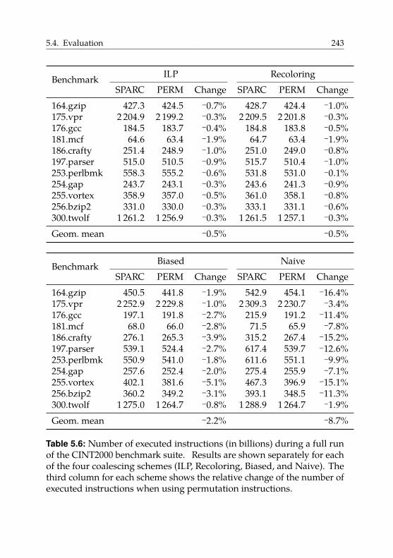
5.4. Evaluation 243
Benchmark ILP RecoloringSPARC PERM Change SPARC PERM Change
164.gzip 427.3 424.5 −0.7% 428.7 424.4 −1.0%175.vpr 2 204.9 2 199.2 −0.3% 2 209.5 2 201.8 −0.3%176.gcc 184.5 183.7 −0.4% 184.8 183.8 −0.5%181.mcf 64.6 63.4 −1.9% 64.7 63.4 −1.9%186.crafty 251.4 248.9 −1.0% 251.0 249.0 −0.8%197.parser 515.0 510.5 −0.9% 515.7 510.4 −1.0%253.perlbmk 558.3 555.2 −0.6% 531.8 531.0 −0.1%254.gap 243.7 243.1 −0.3% 243.6 241.3 −0.9%255.vortex 358.9 357.0 −0.5% 361.0 358.1 −0.8%256.bzip2 331.0 330.0 −0.3% 333.1 331.1 −0.6%300.twolf 1 261.2 1 256.9 −0.3% 1 261.5 1 257.1 −0.3%Geom. mean −0.5% −0.5%
Benchmark Biased NaiveSPARC PERM Change SPARC PERM Change
164.gzip 450.5 441.8 −1.9% 542.9 454.1 −16.4%175.vpr 2 252.9 2 229.8 −1.0% 2 309.3 2 230.7 −3.4%176.gcc 197.1 191.8 −2.7% 215.9 191.2 −11.4%181.mcf 68.0 66.0 −2.8% 71.5 65.9 −7.8%186.crafty 276.1 265.3 −3.9% 315.2 267.4 −15.2%197.parser 539.1 524.4 −2.7% 617.4 539.7 −12.6%253.perlbmk 550.9 541.0 −1.8% 611.6 551.1 −9.9%254.gap 257.6 252.4 −2.0% 275.4 255.9 −7.1%255.vortex 402.1 381.6 −5.1% 467.3 396.9 −15.1%256.bzip2 360.2 349.2 −3.1% 393.1 348.5 −11.3%300.twolf 1 275.0 1 264.7 −0.8% 1 288.9 1 264.7 −1.9%Geom. mean −2.2% −8.7%
Table 5.6: Number of executed instructions (in billions) during a full runof the CINT2000 benchmark suite. Results are shown separately for eachof the four coalescing schemes (ILP, Recoloring, Biased, and Naive). Thethird column for each scheme shows the relative change of the number ofexecuted instructions when using permutation instructions.
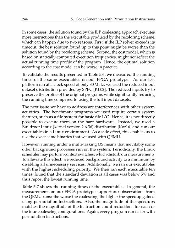
244 5. Code Generation with Permutation Instructions
In some cases, the solution found by the ILP coalescing approach executesmore instructions than the executable produced by the recoloring scheme,which can happen due to two reasons. First, if the ILP solver exceeds itstimeout, the best solution found up to this point might be worse than thesolution found by the recoloring scheme. Second, the cost model, which isbased on statically-computed execution frequencies, might not reflect theactual running time profile of the program. Hence, the optimal solutionaccording to the cost model can be worse in practice.
To validate the results presented in Table 5.6, we measured the runningtimes of the same executables on our FPGA prototype. As our testplatform ran at a clock speed of only 80 MHz, we used the reduced inputdataset distribution provided by SPEC [KL02]. The reduced inputs try topreserve the profile of the original programs while significantly reducingthe running time compared to using the full input datasets.
The next issue we have to address are interferences with other systemactivities. The benchmark programs we used require certain systemfeatures, such as a file system for basic file I/O. Hence, it is not directlypossible to execute them on the bare hardware. Instead, we used aBuildroot Linux (kernel version 2.6.36) distribution [Kor16] and run ourexecutables in a Linux environment. As a side effect, this enables us touse the exact same binaries that we used with QEMU.
However, running under a multi-tasking OS means that inevitably someother background processes run on the system. Periodically, the Linuxscheduler may perform context switches, which disturb our measurements.To alleviate this effect, we reduced background activity to a minimum bydisabling all unnecessary services. Additionally, we ran our executableswith the highest scheduling priority. We then ran each executable tentimes, found that the standard deviation is all cases was below 5% andthus report the lowest running time.
Table 5.7 shows the running times of the executables. In general, themeasurements on our FPGA prototype support our observations fromthe QEMU runs: the worse the coalescing, the higher the speedup gainedusing permutation instructions. Also, the magnitude of the speedupsmatches the magnitude of the instruction count reductions for each ofthe four coalescing configurations. Again, every program ran faster withpermutation instructions.
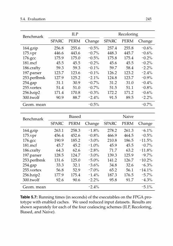
5.4. Evaluation 245
Benchmark ILP RecoloringSPARC PERM Change SPARC PERM Change
164.gzip 256.8 255.6 −0.5% 257.4 255.8 −0.6%175.vpr 446.6 443.6 −0.7% 448.3 445.7 −0.6%176.gcc 175.9 175.0 −0.5% 175.8 175.4 −0.2%181.mcf 45.5 45.5 −0.2% 45.6 45.5 −0.2%186.crafty 59.3 59.3 −0.1% 59.7 58.4 −2.2%197.parser 123.7 123.6 −0.1% 126.2 123.2 −2.4%253.perlbmk 127.9 125.2 −2.1% 124.8 123.7 −0.9%254.gap 31.1 30.9 −0.7% 31.2 31.0 −0.4%255.vortex 51.4 51.0 −0.7% 51.5 51.1 −0.8%256.bzip2 171.4 170.8 −0.3% 172.2 171.2 −0.6%300.twolf 90.9 88.7 −2.4% 91.5 89.5 −2.2%Geom. mean −0.5% −0.7%
Benchmark Biased NaiveSPARC PERM Change SPARC PERM Change
164.gzip 263.1 258.3 −1.8% 278.2 261.3 −6.1%175.vpr 456.4 452.6 −0.8% 466.9 464.5 −0.5%176.gcc 190.9 185.2 −3.0% 210.8 186.5 −11.5%181.mcf 45.7 45.2 −1.0% 45.9 45.5 −0.7%186.crafty 64.3 62.6 −2.8% 71.7 63.2 −11.8%197.parser 128.5 124.7 −3.0% 139.3 125.9 −9.7%253.perlbmk 131.6 125.0 −5.0% 141.2 126.7 −10.2%254.gap 33.3 32.1 −3.6% 34.8 32.6 −6.3%255.vortex 56.8 52.9 −7.0% 65.2 56.1 −14.1%256.bzip2 177.9 175.4 −1.4% 187.3 176.5 −5.7%300.twolf 92.6 90.6 −2.2% 95.8 91.7 −4.3%Geom. mean −2.4% −5.1%
Table 5.7: Running times (in seconds) of the executables on the FPGA pro-totype with enabled caches. We used reduced input datasets. Results areshown separately for each of the four coalescing schemes (ILP, Recoloring,Biased, and Naive).
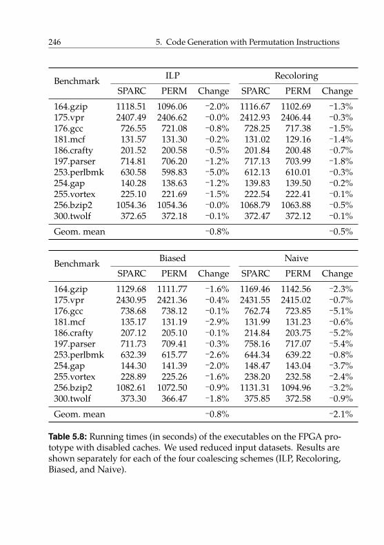
246 5. Code Generation with Permutation Instructions
Benchmark ILP RecoloringSPARC PERM Change SPARC PERM Change
164.gzip 1118.51 1096.06 −2.0% 1116.67 1102.69 −1.3%175.vpr 2407.49 2406.62 −0.0% 2412.93 2406.44 −0.3%176.gcc 726.55 721.08 −0.8% 728.25 717.38 −1.5%181.mcf 131.57 131.30 −0.2% 131.02 129.16 −1.4%186.crafty 201.52 200.58 −0.5% 201.84 200.48 −0.7%197.parser 714.81 706.20 −1.2% 717.13 703.99 −1.8%253.perlbmk 630.58 598.83 −5.0% 612.13 610.01 −0.3%254.gap 140.28 138.63 −1.2% 139.83 139.50 −0.2%255.vortex 225.10 221.69 −1.5% 222.54 222.41 −0.1%256.bzip2 1054.36 1054.36 −0.0% 1068.79 1063.88 −0.5%300.twolf 372.65 372.18 −0.1% 372.47 372.12 −0.1%Geom. mean −0.8% −0.5%
Benchmark Biased NaiveSPARC PERM Change SPARC PERM Change
164.gzip 1129.68 1111.77 −1.6% 1169.46 1142.56 −2.3%175.vpr 2430.95 2421.36 −0.4% 2431.55 2415.02 −0.7%176.gcc 738.68 738.12 −0.1% 762.74 723.85 −5.1%181.mcf 135.17 131.19 −2.9% 131.99 131.23 −0.6%186.crafty 207.12 205.10 −0.1% 214.84 203.75 −5.2%197.parser 711.73 709.41 −0.3% 758.16 717.07 −5.4%253.perlbmk 632.39 615.77 −2.6% 644.34 639.22 −0.8%254.gap 144.30 141.39 −2.0% 148.47 143.04 −3.7%255.vortex 228.89 225.26 −1.6% 238.20 232.58 −2.4%256.bzip2 1082.61 1072.50 −0.9% 1131.31 1094.96 −3.2%300.twolf 373.30 366.47 −1.8% 375.85 372.58 −0.9%Geom. mean −0.8% −2.1%
Table 5.8: Running times (in seconds) of the executables on the FPGA pro-totype with disabled caches. We used reduced input datasets. Results areshown separately for each of the four coalescing schemes (ILP, Recoloring,Biased, and Naive).

5.4. Evaluation 247
To further improve the reliability of our results, we repeated the experi-ments on the FGPA prototype with disabled caches. In the following wewill give details on our test setup and explain our rationale for choosingthis configuration.
To avoid the influence of caches on our measurements, we disabledboth the L1 code cache and the L1 data cache of our system. It is welldocumented [CB13; Myt+09] that the memory layout of code and datacan have a significant impact on the running time. The root cause of thisare architectural features of the underlying hardware whose behaviordepends on memory addresses, mainly caches and branch predictors.
For example, multiple load instructions in a program may compete forthe same cache line, resulting in frequent cache misses. Whether thisactually happens depends on the addresses that are accessed by the loadinstructions as well as on the cache structure. Likewise, some branchpredictors take into account (parts of) the addresses of conditional branchinstructions. Hence, the predictor’s behavior depends on the memorylocation where the branch instruction resides.
Obviously, different executable versions, e.g., with or without permutationinstructions, may result in a different code layout. Unfortunately, manyother factors influence code and data layout as well. Examples includethe ordering of the object files during linking [CB13], the size of the envi-ronment variables [Myt+09], which influences the stack’s starting address,and security features such as address space layout randomization [FSA97],which may randomize, amongst other parameters, the starting addressesof stack and heap.
By disabling the caches, we eliminate the biggest cause of address sensi-tivity from our setup. Moreover, our LEON 3 processor uses the simple“always taken” strategy for its branch prediction [Cob15b, §2.3.1]. Theidea behind this strategy is that for loops, the conditional branch usuallyjumps back to the loop header as most loops run many times and thereforeit makes sense to predict such conditional branches as “always taken”.Hence, the LEON’s branch prediction is independent of the addresses ofbranch instructions. Combined with the deactivation of the caches, wehave thus reduced the influence of memory addresses on the behavior ofour hardware to a minimum.
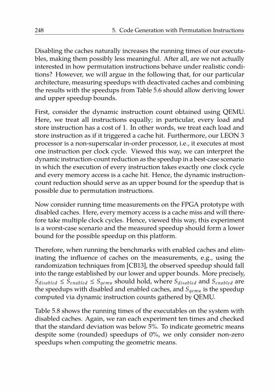
248 5. Code Generation with Permutation Instructions
Disabling the caches naturally increases the running times of our executa-bles, making them possibly less meaningful. After all, are we not actuallyinterested in how permutation instructions behave under realistic condi-tions? However, we will argue in the following that, for our particulararchitecture, measuring speedups with deactivated caches and combiningthe results with the speedups from Table 5.6 should allow deriving lowerand upper speedup bounds.
First, consider the dynamic instruction count obtained using QEMU.Here, we treat all instructions equally; in particular, every load andstore instruction has a cost of 1. In other words, we treat each load andstore instruction as if it triggered a cache hit. Furthermore, our LEON 3processor is a non-superscalar in-order processor, i.e., it executes at mostone instruction per clock cycle. Viewed this way, we can interpret thedynamic instruction-count reduction as the speedup in a best-case scenarioin which the execution of every instruction takes exactly one clock cycleand every memory access is a cache hit. Hence, the dynamic instruction-count reduction should serve as an upper bound for the speedup that ispossible due to permutation instructions.
Now consider running time measurements on the FPGA prototype withdisabled caches. Here, every memory access is a cache miss and will there-fore take multiple clock cycles. Hence, viewed this way, this experimentis a worst-case scenario and the measured speedup should form a lowerbound for the possible speedup on this platform.
Therefore, when running the benchmarks with enabled caches and elim-inating the influence of caches on the measurements, e.g., using therandomization techniques from [CB13], the observed speedup should fallinto the range established by our lower and upper bounds. More precisely,Sdisabled ≤ Senabled ≤ Sqemu should hold, where Sdisabled and Senabled arethe speedups with disabled and enabled caches, and Sqemu is the speedupcomputed via dynamic instruction counts gathered by QEMU.
Table 5.8 shows the running times of the executables on the system withdisabled caches. Again, we ran each experiment ten times and checkedthat the standard deviation was below 5%. To indicate geometric meansdespite some (rounded) speedups of 0%, we only consider non-zerospeedups when computing the geometric means.
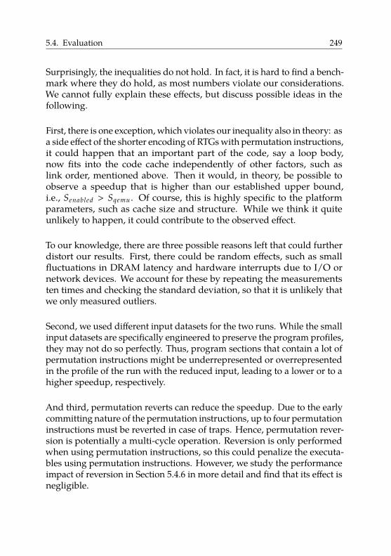
5.4. Evaluation 249
Surprisingly, the inequalities do not hold. In fact, it is hard to find a bench-mark where they do hold, as most numbers violate our considerations.We cannot fully explain these effects, but discuss possible ideas in thefollowing.
First, there is one exception, which violates our inequality also in theory: asa side effect of the shorter encoding of RTGs with permutation instructions,it could happen that an important part of the code, say a loop body,now fits into the code cache independently of other factors, such aslink order, mentioned above. Then it would, in theory, be possible toobserve a speedup that is higher than our established upper bound,i.e., Senabled > Sqemu . Of course, this is highly specific to the platformparameters, such as cache size and structure. While we think it quiteunlikely to happen, it could contribute to the observed effect.
To our knowledge, there are three possible reasons left that could furtherdistort our results. First, there could be random effects, such as smallfluctuations in DRAM latency and hardware interrupts due to I/O ornetwork devices. We account for these by repeating the measurementsten times and checking the standard deviation, so that it is unlikely thatwe only measured outliers.
Second, we used different input datasets for the two runs. While the smallinput datasets are specifically engineered to preserve the program profiles,they may not do so perfectly. Thus, program sections that contain a lot ofpermutation instructions might be underrepresented or overrepresentedin the profile of the run with the reduced input, leading to a lower or to ahigher speedup, respectively.
And third, permutation reverts can reduce the speedup. Due to the earlycommitting nature of the permutation instructions, up to four permutationinstructions must be reverted in case of traps. Hence, permutation rever-sion is potentially a multi-cycle operation. Reversion is only performedwhen using permutation instructions, so this could penalize the executa-bles using permutation instructions. However, we study the performanceimpact of reversion in Section 5.4.6 in more detail and find that its effect isnegligible.
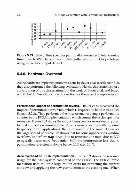
250 5. Code Generation with Permutation Instructions
● ●
●
●
●●
●
●●
● ●
10−810−710−610−510−410−3
164.
gzip
175.
vpr
176.
gcc
181.
mcf
186.
craf
ty
197.
pars
er
253.
perlb
mk
254.
gap
255.
vorte
x
256.
bzip2
300.
twolfre
vert
tim
e / t
otal
tim
e
Figure 5.33: Ratio of time spent for permutation reversion to total runningtime of each SPEC benchmark. Data gathered from FPGA prototypeusing the reduced input dataset.
5.4.6. Hardware Overhead
As the hardware implementation was done by Bauer et al. (see Section 5.2),they also performed the following evaluation. Hence, this section is not acontribution of this dissertation, but the work of Bauer et al. and basedon [Moh+13]. We still include this section for the sake of completeness.
Performance impact of permutation reverts. Bauer et al. measured theimpact of permutation reversion, which is required to handle traps (seeSection 5.2.2). They performed the measurements using a performancecounter in the FPGA implementation, which counts the cycles spent forreversion. Figure 5.33 shows the ratio of time spent for reversion comparedto total application running time. If traps were occurring with the samefrequency for all applications, the ratio would be the same. However,the large spread of nearly 104 shows that for some applications windowoverflow/underflow traps (e.g., due to recursion) or traps due to I/Oor syscalls occur more frequently. Still, the performance loss due topermutation reversion is always below 0.1% (i.e., 10−3).
Area overhead of FPGA implementation. Table 5.9 shows the resourceusage for the base system compared to the PERM. The PERM imple-mentation uses multiple large multiplexers for extracting the currentwindow and applying the new permutation to the existing one. When
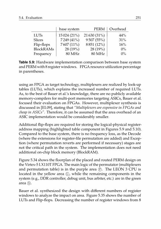
5.4. Evaluation 251
base system PERM OverheadLUTs 15 024 (21%) 21 630 (31%) 44%Slices 7 249 (41%) 9 507 (55%) 31%Flip-flops 7 607 (11%) 8 851 (12%) 16%BlockRAMs 28 (19%) 28 (19%) 0%Frequency 80 MHz 80 MHz 0%
Table 5.9: Hardware implementation comparison between base systemand PERM with 8 register windows. FPGA resource utilization percentagein parentheses.
using an FPGA as target technology, multiplexers are realized by look-uptables (LUTs), which explains the increased number of required LUTs.As, to the best of Bauer et al.’s knowledge, there are no publicly availablememory-compilers for multi-port memories targeting ASICs, Bauer et al.focused their evaluation on FPGAs. However, multiplexer synthesis isdiscussed in [EL09], stating that “Multiplexers are expensive in FPGAs and
cheap in ASICs”. Therefore, it can be assumed that the area overhead of anASIC implementation would be considerably smaller.
Additional flip-flops are required for storing the logical-physical register-address mapping (highlighted table component in Figures 5.9 and 5.10).Compared to the base system, there is no frequency loss, as the Decode(where the extensions for register-file permutation are added) and Excep-tion (where permutation reverts are performed if necessary) stages arenot the critical path in the system. The implementation does not needadditional on-chip block memory (BlockRAM).
Figure 5.34 shows the floorplan of the placed and routed PERM design onthe Virtex-5 LX110T FPGA. The main logic of the permutator (multiplexersand permutation table) is in the purple area P○. The LEON 3 CPU islocated in the yellow area L○, while the remaining components in thesystem (e.g., DDR controller, debug unit, bus arbiter, etc.) are in the greenarea S○.
Bauer et al. synthesized the design with different numbers of registerwindows to analyze the impact on area. Figure 5.35 shows the number ofLUTs and Flip-flops. Decreasing the number of register windows from 8
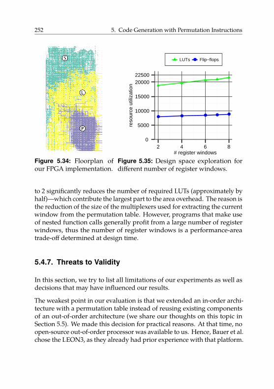
252 5. Code Generation with Permutation Instructions
Figure 5.34: Floorplan ofour FPGA implementation.
● ● ● ● ●
0
5000
10000
15000
2000022500
2 4 6 8# register windows
reso
urce
util
izat
ion
●●LUTs Flip−flops
Figure 5.35: Design space exploration fordifferent number of register windows.
to 2 significantly reduces the number of required LUTs (approximately byhalf)—which contribute the largest part to the area overhead. The reason isthe reduction of the size of the multiplexers used for extracting the currentwindow from the permutation table. However, programs that make useof nested function calls generally profit from a large number of registerwindows, thus the number of register windows is a performance-areatrade-off determined at design time.
5.4.7. Threats to Validity
In this section, we try to list all limitations of our experiments as well asdecisions that may have influenced our results.
The weakest point in our evaluation is that we extended an in-order archi-tecture with a permutation table instead of reusing existing componentsof an out-of-order architecture (we share our thoughts on this topic inSection 5.5). We made this decision for practical reasons. At that time, noopen-source out-of-order processor was available to us. Hence, Bauer et al.chose the LEON3, as they already had prior experience with that platform.
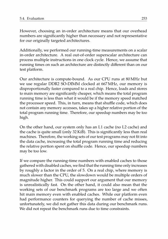
5.4. Evaluation 253
However, choosing an in-order architecture means that our overheadnumbers are significantly higher than necessary and not representativefor our originally targeted architectures.
Additionally, we performed our running-time measurements on a scalarin-order architecture. A real out-of-order superscalar architecture canprocess multiple instructions in one clock cycle. Hence, we assume thatrunning times on such an architecture are distinctly different than on ourtest platform.
Our architecture is compute-bound. As our CPU runs at 80 MHz butwe use regular DDR2 SO-DIMM clocked at 667 MHz, our memory isdisproportionally faster compared to a real chip. Hence, loads and storesto main memory are significantly cheaper, which means the total programrunning time is less than what it would be if the memory speed matchedthe processor speed. This, in turn, means that shuffle code, which doesnot contain any memory accesses, takes up a higher relative portion of thetotal program running time. Therefore, our speedup numbers may be toohigh.
On the other hand, our system only has an L1 cache (no L2 cache) andthe cache is quite small (only 32 KiB). This is significantly less than realmachines. Therefore, the working sets of our test programs may not fit intothe data cache, increasing the total program running time and reducingthe relative portion spent on shuffle code. Hence, our speedup numbersmay be too low.
If we compare the running-time numbers with enabled caches to thosegathered with disabled caches, we find that the running time only increasesby roughly a factor in the order of 5. On a real chip, where memory ismuch slower than the CPU, the slowdown would be multiple orders ofmagnitude higher. This could support our argument that our memoryis unrealistically fast. On the other hand, it could also mean that theworking sets of our benchmark programs are too large and we oftenhit main memory even with enabled caches. While our platform evenhad performance counters for querying the number of cache misses,unfortunately, we did not gather this data during our benchmark runs.We did not repeat the benchmark runs due to time constraints.
254 5. Code Generation with Permutation Instructions
Additionally, multiple factors increase the cost of shuffle code on ourplatform. First, the SPARC instruction set has no swap instruction onregisters. Hence, if there is no free register at the program point of theRTG, its implementation must use three xor instructions to implementeach transposition. Here, it would have been interesting to compare codequality of full permutation support to a baseline where we restrictedthe use of permi to swaps, i.e., use permi to emulate the missing swapinstruction. However, we did not perform this experiment due to timeconstraints.
Second, our prototype did not have an FPU. Hence, we compiled allprograms in soft-float mode. In this mode, all floating-point computationsare performed on integer registers. Hence, for programs that usedfloat-point computations this overstates the amount of shuffle code forinteger registers. However, only two programs of our integer benchmarkset make noteworthy use of floating-point arithmetics: 175.vpr and300.twolf47. Hence, for all other programs, the amount of shuffle code isrepresentative.
Third, the SPARC calling convention passes the first six function argumentsin registers (the rest via the stack). Hence, in general, there is an RTGbefore every call, except if coalescing can make the RTG trivial. Thisincreases the amount of shuffle code in comparison to, e.g., 32-bit x86code, where all arguments are passed via the stack. However, passingregisters is more common, and, e.g., the 64-bit x86 ABI and ARM ABI alsouse registers to pass arguments. Hence, we do not consider this an unfairadvantage for our technique.
Lastly, we suspect register permutations to be interesting in just-in-timecompilation scenarios. However, we did not test them in that context.There could be other factors, e.g., more inefficient code in general dueto compilation-time constraints, that could reduce the relative amountof running time spent on shuffle code. Hence, the benefit of usingpermutation instructions in that context could be lower than one wouldexpect from our results.
47This also explains the high number of executed instructions of these two benchmarks inTable 5.6.
5.5. Generalization 255
5.5. Generalization
We saw in Section 5.4.6 that implementing permutation instructions inan existing in-order architecture has a high area overhead. While thisimplementation allowed us to evaluate our concept more thoroughly, thereal aim of permutation instructions are out-of-order architectures asmentioned in the initial motivation of this chapter. In this section, wefirst give a more detailed overview of an implementation technique forout-of-order execution. Based on this presentation, we then argue thatpermutation instructions could be added cheaply in this context, anddiscuss their advantages.
5.5.1. Out-of-Order Execution
A simple pipelined processor (e.g., see Section 5.2.1) executing instructionsin-order can experience pipeline stalls due to data dependencies. Forexample, suppose that we have a processor where division takes more thanone cycle. Furthermore, suppose that this processor has two functionalunits that can both handle division and multiplication. Now, consider thefollowing sequence of instructions:
i1: r1 ← div r2, r3i2: r4 ← mul r1, r1i3: r4 ← mul r6, r7
Here, the multiplication i2 is data-dependent on the division i1 as itrequires the computed quotient in register r1. However, division is amulti-cycle operation. Thus, i2 has to wait for the result of i1. In fact,as instruction i2 cannot progress through the pipeline stages, no otherinstruction can progress through earlier stages, such as instruction fetchor decode. Hence, the pipeline is halted or stalled until the long-runningdivision has finished.
In this example, i3 is not data-dependent on the previous two instructionsand could be executed on the second functional unit, which is idle duringexecution of the division. However, this requires executing the instructionsof the program in an order that is different from the program order.
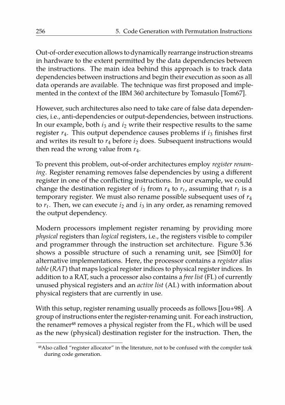
256 5. Code Generation with Permutation Instructions
Out-of-order execution allows to dynamically rearrange instruction streamsin hardware to the extent permitted by the data dependencies betweenthe instructions. The main idea behind this approach is to track datadependencies between instructions and begin their execution as soon as alldata operands are available. The technique was first proposed and imple-mented in the context of the IBM 360 architecture by Tomasulo [Tom67].
However, such architectures also need to take care of false data dependen-cies, i.e., anti-dependencies or output-dependencies, between instructions.In our example, both i3 and i2 write their respective results to the sameregister r4. This output dependence causes problems if i3 finishes firstand writes its result to r4 before i2 does. Subsequent instructions wouldthen read the wrong value from r4.
To prevent this problem, out-of-order architectures employ register renam-
ing. Register renaming removes false dependencies by using a differentregister in one of the conflicting instructions. In our example, we couldchange the destination register of i3 from r4 to rt , assuming that rt is atemporary register. We must also rename possible subsequent uses of r4to rt . Then, we can execute i2 and i3 in any order, as renaming removedthe output dependency.
Modern processors implement register renaming by providing morephysical registers than logical registers, i.e., the registers visible to compilerand programmer through the instruction set architecture. Figure 5.36shows a possible structure of such a renaming unit, see [Sim00] foralternative implementations. Here, the processor contains a register alias
table (RAT) that maps logical register indices to physical register indices. Inaddition to a RAT, such a processor also contains a free list (FL) of currentlyunused physical registers and an active list (AL) with information aboutphysical registers that are currently in use.
With this setup, register renaming usually proceeds as follows [Jou+98]. Agroup of instructions enter the register-renaming unit. For each instruction,the renamer48 removes a physical register from the FL, which will be usedas the new (physical) destination register for the instruction. Then, the
48Also called “register allocator” in the literature, not to be confused with the compiler taskduring code generation.
5.5. Generalization 257
RAT
FL AL
Renamer
logicalregisters
physicalregisters
updates
reclaim on retirement
Figure 5.36: Register-renaming unit using a register alias table (RAT). TheRAT maps logical to physical register indices. The free list FL containscurrently unused physical registers. The active list AL contains informationabout physical registers that are in use.
258 5. Code Generation with Permutation Instructions
RAT and the AL are updated according to the new mapping from logicalto physical registers.
Accesses to the destination register by subsequent instructions will usethe register’s logical register name and will thus be rerouted to the correctphysical register by the RAT. Hence, the destination register has effectivelybeen renamed. Once the instruction has finished executing and its resultsare visible in the architectural state (when the instruction has retired), thephysical register is reclaimed and transferred from the AL to the FL.
5.5.2. Implementing Permutation Instructions
In this section, we argue that permutation instructions should be cheap toimplement on modern high-performance processors that already supportout-of-order execution and register renaming to exploit instruction levelparallelism.
Once a RAT as presented in the previous section is available, we canimplement certain operations by just modifying this table. Hence, wehandle these instructions during the renaming phase and do not need toactually execute them on a functional unit of the processor. For example,current Intel microprocessors implement [Int16, §2.2.2] the move elimination
technique [Tom67; Jou+98]. These processors implement copy (or move)instructions such as copy r1, r2 by changing the RAT mapping of r2 topoint to the physical register that r1 currently points to. Registers r1 andr2 now effectively share a value saved in a single physical register.
To ensure correctness, these processors save a reference counter perphysical register [Jou+98, section 2.2]. Registers in the free list FL have areference count of 0. Whenever a physical register is allocated, its referencecount is incremented. When a physical register is reclaimed, its countervalue is decremented. During retirement, we only transfer a register to thefree list if its reference count is 0. Hence, compared to our permutationtable, a reference counter enables mapping multiple logical registers tothe same physical register. Such a RAT is thus strictly more powerful thanour permutation table.
Other applications of the RAT are exploiting so-called zero idioms andimplementing certain exchange instructions. Zero idioms [Int16, §3.5.1.8]
5.5. Generalization 259
denote instructions that set a register to zero, e.g., xor reg, reg. Therenamer recognizes these idioms and modifies the RAT so that reg pointsto a special physical register that is permanently set to zero. Hence,these instructions are also executed without being passed to a functionalunit. The renamer also handles the floating-point instruction fxch, whichexchanges two floating-point registers49 [Int16, §2.3.3.1].
We argue that with a RAT already in place, adding permutation instruc-tions should be cheap. As we see from the support for fxch instructions,swapping two registers is possible and already implemented in commonprocessors. The only difference for permutation instructions is that theychange more than two (in our case up to five) entries in the RAT at once.According to a detailed study of Intel’s microarchitecture [Fog16, sections8.7 and 9.8], Intel processors can rename up to four registers in one clockcycle.
Assume that we add a permutation instruction to the instruction set ofsuch an out-of-order processor. Once a permutation instruction arrives atthe renaming unit, the unit is completely occupied for one clock cycle asthe instruction exhausts the available renaming capabilities. Hence, noother instructions can be subject to renaming in the same cycle. However,the permutation instructions still offer benefits: they are a more compactencoding of the wanted operation, and they may reduce latency.
First, compared to expressing the permutation as a series of exchangeoperations, the permutation instruction is more compact as it avoidsrepeating register names. For example, to do a cyclic shift of registersr1, r2, r3, the encoding of permi r1, r2, r3 is more compact than doingswap r2, r3 followed by swap r1, r2.
And second, the permutation instruction may have a lower latency. In theexample, the second swap instruction has a true data dependency on thefirst swap instruction, as it reads register r2, which is written by the firstswap instruction. Hence, depending on the capabilities of the renaminghardware, this dependency may prevent renaming these instructionsin the same cycle. However, according to [Fog16, section 9.8], somemodern microarchitectures also support eliminating “chained movs”,
49To be precise, as x87 floating-point registers are organized as a stack, fxch allowsexchanging an arbitrary floating-point register with the register on top of the stack.
260 5. Code Generation with Permutation Instructions
i.e., sequences such as copy r1, r2; copy r2, r3. Here, the secondinstruction has a true data dependency on the first. If a microarchitectureis able to rename such dependent instructions in the same clock cycle, itcould also rename multiple dependent swap instructions as those shownbefore. Then permutation instructions would offer no latency benefits.Only if the hardware does not support renaming dependent instructionsin the same clock cycle do permutation instructions offer an advantageregarding latency.
In summary, we are confident that adding support for permutationinstructions to a modern out-of-order processor is possible with lowimplementation overhead. However, the benefit may be limited: if theprocessor supports renaming dependent instructions in a single clockcycle, permutation instructions only provide a more compact encoding ofRTGs. A more compact encoding is, in general, beneficial; for example, ithelps for keeping tight loops in the code cache. However, the performanceimpact of a more compact encoding is difficult to quantify due to sensitivityconcerning addresses or cache structure.
Regarding code generation, a RAT with a reference counter per physi-cal register is strictly more powerful than our permutation table fromSection 5.2 as it also allows mapping multiple logical registers to thesame physical register. This would enable more powerful instructions toimplement RTGs that also allow value duplication. However, it wouldalso require different instruction formats and different code generationapproaches to exploit the more powerful hardware.
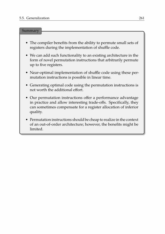
5.5. Generalization 261
Summary
• The compiler benefits from the ability to permute small sets ofregisters during the implementation of shuffle code.
• We can add such functionality to an existing architecture in theform of novel permutation instructions that arbitrarily permuteup to five registers.
• Near-optimal implementation of shuffle code using these per-mutation instructions is possible in linear time.
• Generating optimal code using the permutation instructions isnot worth the additional effort.
• Our permutation instructions offer a performance advantagein practice and allow interesting trade-offs. Specifically, theycan sometimes compensate for a register allocation of inferiorquality.
• Permutation instructions should be cheap to realize in the contextof an out-of-order architecture; however, the benefits might belimited.

Dissertations are not finished; they are abandoned.
Frederick P. Brooks, Jr.
6Conclusion and Future Work
We have made contributions regarding compilation and code generationalong both dimensions of modern parallel architectures: memory andcore design. In the first part of this dissertation, we presented an in-depthoverview of non-cache-coherent architectures and explained the cost andtrade-offs of implementing common programming models. We then tooka concrete example as a case study, namely compiling the PGAS languageX10 to invasive many-core architectures. Based on this platform, weidentified data transfers between coherence domains as a crucial buildingblock for efficient program execution. We exhaustively studied possibleimplementation techniques and trade-offs. Moreover, we developed anovel approach to avoid serialization of complex data structures throughautomatic compiler-directed software-managed coherence. We performedan extensive evaluation of data-transfer techniques on a prototype of aninvasive many-core architecture. We could show using programs froman existing benchmark suite that our novel approach provides a speedup.Moreover, we investigated hardware acceleration for range-based cacheoperations and evaluated benefits and overheads.
Regarding code generation, we investigated the use of permutation in-structions to allow implementing shuffle code more efficiently. Startingfrom a design driven by hardware constraints, we built a solid theoretical
263
264 6. Conclusion and Future Work
foundation for our problem setting. We developed two code generationapproaches and proved multiple optimality guarantees about them. Wethen evaluated both approaches on an actual hardware prototype andcould show that our extension provides a speedup and enables interestingtrade-offs. We also discussed the implementation of such instructions onmodern out-of-order architectures.
In the following, we take a step back and share our ideas for possibleresearch directions in the future.
Compilation to invasive architectures. In our opinion, our most im-portant realization concerning invasive architectures is that support forfine-grained cache control is useful and enables efficient program exe-cution. We think that right now, this topic does not get the attention itdeserves. The lack of such fine-grained control is one of the most promi-nent points of criticism of the Intel SCC, which has a structure similar toinvasive architectures. The Invasive Computing project is in the uniqueposition that it can actually adapt and improve its hardware platform. Ourclear recommendation is to add support for fine-grained cache control.We advise against putting too much logic into the hardware; functionalityto write back or invalidate the relevant cache line for a given address issufficient.
We also strongly recommend to add support for off-chip memory to theexisting DMA units. Currently, copying data forth and back betweenoff-chip memory and TLM using regular loads and stores often negatesthe performance advantage of using hardware-accelerated asynchronoustransfers. There is no conceptual reason why the current DMA units arelimited to TLMs. In conjunction with fine-grained cache control, thiswould enable very efficient implementation [CS16; CS17] of one-sidedblock-wise communication means, such as Array.asyncCopy() in X10.As our memory tile contains some cores close to off-chip memory, itwould even be possible to realize the idea of van Tol et al. [Tol+11] and letdedicated copy cores located on the memory tile handle off-chip memorytransfers asynchronously without causing any NoC traffic.
It could be interesting to implement the idea of remote invalidation (andits dual operation remote writeback) for true one-sided communication
265
as proposed by Christgau et al. [CS16; CS17]. These operations wouldlikely be implemented either in the network adapter of a tile, in the cachecontrollers, or in a combination of both. We suspect that it is possibleto reuse some of our work on range operations that we presented inSection 4.5.
We give more technical details on our ideas for improvements of invasivearchitectures in Appendix A.1. There, we provide lists of concrete imple-mentation steps that we suspect would improve the system as a wholeand make it more efficient.
Our main focus in Chapter 4 was the acceleration of copying data struc-tures between memory partitions on non-cache-coherent architectures.However, avoiding copies altogether would be even more worthwhile.Friedley et al. [Fri+13] propose ownership passing for MPI programs onclusters. As mentioned before, clusters usually provide shared memoryinside a node and use message passing between nodes. However, manyapplication developers use message passing also inside a node to avoidhaving to combine multiple programming models.
Friedley et al. propose to avoid copying buffers if shared memory isavailable and avoiding the copy does not change program semantics. Inthis case, they transfer the ownership of the buffer, i.e., hand over a singlepointer, instead of copying the complete buffer. They devise a data-flowanalysis [ASU86, section 9.2] to identify where ownership passing isapplicable, and a matching compiler transformation to automaticallyapply ownership passing. They mention [Fri+13, section 3] that theirapproach is also usable on non-cache-coherent architectures, but did notevaluate it there.
In the context of Invasive Computing, we can envision a similar compiler-based technique for X10. Especially when distributing input data, whichis only read but not modified, it could be worthwhile to avoid copies.It should be possible to apply approaches based on escape and shapeanalysis used for detecting read-only methods in Java [Bog00] to X10’s atblocks. We expect the object-oriented nature of X10 to be a challenge dueto frequent aliasing.
Regarding correctness, it may be interesting to look at formal verificationof (partially) software-based coherence protocols. There is a large body
266 6. Conclusion and Future Work
of work on verifying hardware-based coherence protocols; e.g., recently,Li et al. [Li+16] presented an approach that generates Isabelle [NPW02]proofs. However, to the best of our knowledge, no machine-checkedformalizations exist of software-based coherence protocols or hybridprotocols with software and hardware components.
As a long-term research direction, we can envision the comparison ofmultiple programming models on invasive architectures. So far, we havefocused on the PGAS programming model using X10. As we have seen inChapter 2, other programming models are feasible as well. Additionally,as our hardware is not fixed, we can add the required features to lower thecosts of implementing, e.g., the shared-memory programming model.
Moreover, at the time of writing, there is an ongoing effort [Sri+17] toenable invasive hardware to dynamically and selectively combine multipletiles into a single coherence domain. In our opinion, this allows to explorean interesting design space. We have multiple programming models withdifferent requirements and can either avoid coherence-related problems(e.g., with message passing), provide it (at least partially) in software (e.g.,via the compiler or operating system), or provide it in hardware (usingthe aforementioned extension).
To the best of our knowledge, no comprehensive study exists on whichprogramming model is the most suitable for non-cache-coherent archi-tectures. Many papers propose a multitude of programming models andevaluate them on, e.g., the Intel SCC. In our experience, the PGAS model isa good match. Just like non-cache-coherent shared-memory architecturesare situated somewhere between shared-memory and message-passing ar-chitectures, the PGAS model positions itself between the shared-memoryand message-passing programming models. However, we do not know ofa solid comparison that takes into account a wider range of programmingmodels and supports the comparison with empirical data gathered onreal non-cache-coherent hardware. Future work in the scope of InvasiveComputing could close this gap.
Code generation using permutation instructions. From the theoreticalside, it would be interesting to generalize our greedy algorithm to largerpermutations. We proved in Chapter 5 that our greedy algorithm finds
267
optimal solutions for expressing a permutation as a product of permuta-tions of maximum size 5 (for our definition of permutation size). What ifwe want to find optimal solutions using permutations of maximum size k?Rutter proved that the shuffle-code-generation problem is NP-complete ifk is part of the input (see Appendix A.3). However, if k is fixed, we suspectthat for every maximum size k, we can find an optimal greedy algorithm.That algorithm may increase exponentially in size due to combinatorialexplosion of the necessary case distinction. Still, we suspect that such agreedy algorithm exists for every k.
As we have seen in Section 5.5, on real out-of-order microarchitectures, wecould even express more powerful operations that copy values and not justpermute them. It would be interesting to explore what an instruction setextension would look like if it enabled permuting as well as copying valuesbetween multiple registers. Also, this would require new code-generationalgorithms. We suspect that these algorithms would differ substantiallyfrom our current ones.
From the practical side, it would be interesting to look at parallel-copy-motion techniques [Bou+10; BC13]. By default, these techniques usecost models that target traditional architectures with copy and swapinstructions. However, it could be interesting to tailor a cost model topermutation instructions and see if that produces more efficient code.
Moreover, we would like to explore permutation instructions (or evenmore powerful ones as mentioned above) on a real out-of-order microar-chitecture. One possibility is to integrate the extension into an open-sourceout-of-order core, such as BOOM v2 [Cel+17]. Here, our goal would be toget a better idea of the costs and benefits of additional instructions in thecontext of an architecture that already has some necessary components.After our discussion in Section 5.5, we suspect that the benefits are notworth the effort. However, in our opinion, this suspicion is best provedby an actual implementation. Another possibility is to use a tool for ar-chitectural simulation, such as Gem5 [Bin+11]. Here, we could gather nohardware overhead numbers, but at least perform representative runningtime measurements on an out-of-order architecture.

Just one more thing. . .
Columbo
AAppendix
A.1. Recommendations for InvasiveArchitectures
In this section, we make concrete recommendations for improvements ofinvasive architectures in general, and the prototype platform in specific.We describe our conclusions from Chapter 6 with more technical depthand list concrete implementation steps. We cover both hardware andsoftware components.
We agree with Christgau et al. [CS16; CS17] that software-managedcoherence for efficient one-sided communication is important on non-cache-coherent architectures. We showed in Section 4.6.3 that this alsoapplies to invasive architectures and in Section 4.7 that it is especiallyimportant for invasive programs.
Concerning flat data structures, this requires an efficient implementationof asynchronous copy operations, e.g., Rail.asyncCopy() in X10. To reachthis goal, the following steps are necessary (preferably to be implementedin that order):
269
270 A. Appendix
1. Add support for fine-grained cache control to the L1 caches. Weshowed in Section 4.6.5 that functionality to write-back and invalidatethe relevant cache line for a given address is sufficient. The functionalityin the L2 cache can serve as a model. As our L1 caches are configuredin write-through mode, invalidation is sufficient.
2. Add support for off-chip memory, i.e., DRAM, to the DMA units.Ideally, DMA units would not only issue loads and stores but use largerburst transfers via the NoC. Alternatively, we could offload memorycopy operations to the LEON cores present on our memory tile to avoidNoC traffic completely. We suspect that the prototype platform wouldbenefit greatly from this approach. However, we think it is of limiteduse regarding realistic architectures, as they are unlikely to have anycores positioned near memory.
3. Ideally, add support for remote invalidations (as proposed by Christ-gau et al. [CS16]) and remote write-backs. Remote invalidations enabletrue one-sided copying from local memory to remote memory. Remotewrite-backs enable true one-sided copying from remote memory tolocal memory. We suspect that it is possible to implement such remotecache operations on our platform by a collaboration of network adapterand cache controllers. For example, if tile A issues a remote invalidationto tile B, the network adapter of tile B would receive this request andbroadcast it on B’s local bus. Subsequently, all of B’s cache controllerswould snoop this request and then execute the invalidation on B’scaches. As such remote operations should proceed without softwareinvolvement, we suspect that our insights from Section 4.5 can beuseful. In particular, a design where the network adapter delegatesinvalidations or write-backs to the cache controllers could completelyreuse our work on range operations.
Concerning pointered data structures, we recommend the following steps(preferably to be implemented in that order):
1. Use a static (or even better, a hybrid) allocation approach for TLMs.Our results from Section 4.6.4.2 show that most object graphs are quitesmall. We recommend to extend the X10 runtime system to reserve afixed portion of each TLM for transferring small object graphs withoutrequiring a forth-and-back communication to allocate memory in theremote TLM. It may be worthwhile to investigate directly serializingobject graphs into the TLM of the receiving tile, and then using software-
A.2. The Intermediate Representation Firm 271
managed coherence (see above). This avoids the overhead for copyingdata between TLMs.
2. Use cloning only as an opt-in mechanism as it is, in general, incompatiblewith custom serialization formats. We think adding an annotationso that programmers can switch to cloning for performance-criticaltransfers would be a viable way.
A.2. The Intermediate Representation FirmFirm is graph-based intermediate representation (IR) for compilers [BBZ11].The project was started in 1996 as the IR for the Sather-K compilerFiasco [AR96], giving Firm its name: Fiasco’s Intermediate RepresentationMesh. Today, libFirm [Fir17] provides an open-source implementation ofFirm as well as multiple frontends and code-generation backends.
Firm represents programs based on the “sea of nodes” idea by Click [CP95;Cli95]. Each function of the program is represented by a graph, wherenodes represent operations and directed edges represent both data flowand control flow. In contrast to representations relying on instruction lists,the graph representation only defines a partial order on the operations.Hence, it makes the compiler’s degrees of freedom explicit concerning,e.g., evaluation order.
As an example, we look at the following function that computes themaximum of its two signed integer parameters:
int max(int x, int y){int res;if (x > y)res = x;elseres = y;return res;}
In the following, we will give a brief explanation of how Firm models thisfunction. We refer to [BBZ11] for details.
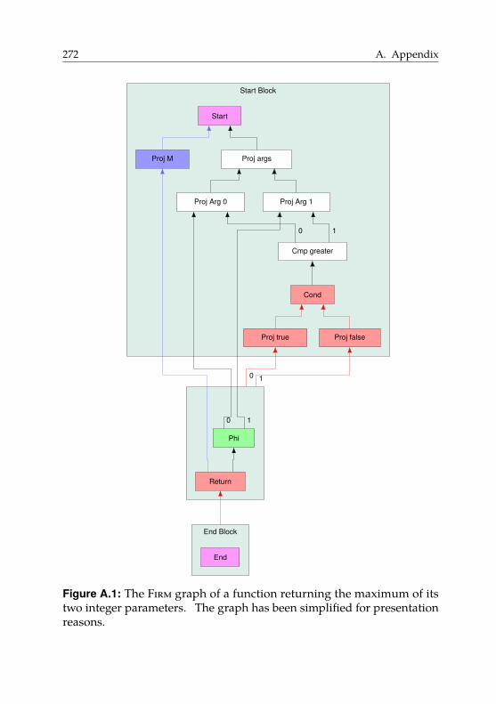
272 A. Appendix
Start Block
End Block
Return
Phi
End
Proj M
Proj true Proj false
Cond
Cmp greater
Proj Arg 0 Proj Arg 1
Proj args
Start
0 1
0 1
0 1
Figure A.1: The Firm graph of a function returning the maximum of itstwo integer parameters. The graph has been simplified for presentationreasons.
A.2. The Intermediate Representation Firm 273
Figure A.1 shows a Firm graph of the function max. The graph has beensimplified for presentation reasons. Note that the direction of edges inFirm is backwards, i.e., edges go from the dependent operation to theoperation it depends on. This applies to both reversed data-flow edges(shown in black) and reversed control-flow edges (shown in red).
We see that there are three basic blocks: the start block, a middle block,and the end block. The start block contains most of the program logic.First, it compares the two function arguments using a Cmp node. Thearguments are retrieved using Proj nodes. As proposed by Click [CP95] forefficiency reasons, Firm models operations that produce multiple resultsas nodes that produce a result tuple. The desired component of a tuple isthen extracted (or “projected out”) using a Proj node. Hence, we have oneProj node for each function argument value. Following the comparison,the Cond node uses the truth value carrying the result of the comparisonand produces a tuple containing control-flow information. In our example,we branch to the same basic block regardless of the comparison result.
In the second basic block, we see a Phi node. The Phi node always hasexactly as many operands as its basic block has predecessors in the control-flow graph. Following the semantics of φ-functions, the Phi node selectsoperand 0 (corresponding to parameter x) if its basic block is entered viaedge 0 (if x > y), or it selects operand 1 (corresponding to parameter y)if its basic block is entered via edge 1 (if x <= y). The resulting value isreturned by the Return node.
Actually, Firm nodes are weakly typed. The types are called “modes”50.We omitted modes in our example graph for presentation reasons.
Other notable properties of Firm and libFirm are:
• libFirm directly constructs SSA form without taking a detour viaa non-SSA IR [Bra+13]. Moreover, optimizations, such as constantfolding, are performed during construction of the IR.
• libFirm performs SSA-based register allocation [Hac07]. This enableslibFirm to retain SSA form of programs even in its backend.
• Firm models memory (and side effects in general) as a special Memoryvalue. If Firm can prove operation independence, multiple Memoryvalues can coexist and are only joined when needed.
50Which probably comes from Algol 68.

274 A. Appendix
A.3. k-Shuffle Code Generation is NP-complete
Throughout this dissertation we have assumed that our permutationinstructions may arbitrarily permute up to five registers. Rutter consideredthe case where a permutation instruction may permute up to k registersarbitrarily. We call such a shuffle code a k-shuffle code. The problemk-shuffle code generation asks for a shortest k-shuffle code that implements agiven RTG. Rutter shows that k-shuffle code generation is NP-complete if kis part of the input. Moreover, Rutter presents an approximation algorithmfor k-shuffle code generation. These results are not a contribution of thisdissertation, but are original (and at the time of writing unpublished)work by Rutter.
A.3.1. Complexity
Here we refer to the decision version of the k-shuffle code generationproblem where the task is to decide the existence of a k-shuffle code withlength at most b.
Theorem 4 k-shuffle code generation is NP-complete for PRTGs. 2
Proof The problem is clearly in NP, since we can guess a shuffle codeand verify that it implements the given PRTG and has size at most b.
To show NP-hardness, Rutter gives a reduction from the strongly NP-complete problem 3-Partition [GJ90]. An instance (A, B) of 3-Partitionconsists of an integer bucket size B and a multiset A � {a1 , . . . , a3m} of 3mintegers such that B/4 < ai < B/2. The task is to decide whether A canbe partitioned into sets S1 , . . . , Sm such that
∑a∈S j
a � B for each S j . Notethat due to the restrictions on the ai , each set of the partition necessarilycontains precisely three elements.
Given an instance (A, B) of 3-Partition, we define a PRTG G that containsfor each element ai a directed cycle Ci of length ai . Since 3-Partition isstrongly NP-complete, we can assume that the ai and B are polynomiallybounded in m. The reduction can then be carried out in polynomial time.We claim that G admits a B-shuffle code of length m if and only if (A, B)is a yes-instance of 3-Partition.
A.3. k-Shuffle Code Generation is NP-complete 275
Given a partition S1 , . . . , Sm , we create for each S j � {ax , ay , az} a corre-sponding instruction that resolves exactly the cycles Cx , Cy , and Cz , whichby assumption consist of exactly B vertices.
Conversely, assume we have a shuffle code consisting of m operations.By construction, the PRTG G has mB vertices and none of them has aself-loop, i.e., each vertex has to be touched by at least one operation.However, each operation can touch at most B vertices, and hence everyvertex is touched exactly once. This in turn implies that every vertex thatis touched by an operation must be mapped to the target of its singleoutgoing edge by this operation. It follows that if an operation touchesany vertex of a cycle, then it must resolve this cycle completely. It thusfollows that every operation resolves exactly three cycles whose total sizeis B. Thus, the operations define a solution of 3-Partition. �
A.3.2. Approximation AlgorithmRutter presents a simple linear-time approximation algorithm for k-shufflecode generation.Lemma 20 A (1 + 1/k)-approximation of an optimal k-shuffle code can be
computed in linear time. 2
Proof By Lemma 1 an optimal shuffle code exists with N �∑
v∈V max{deg(v)−1, 0} copy operations, and in fact every shuffle code uses at least N copyoperations. Let Copt denote an optimal copy set and let Gopt � G − Copt.Let Kopt denote the number of vertices that are incident to a non-loop edgein Gopt. Clearly, each of these vertices has to be touched by at least onepermutation instruction, each of which can touch up to k registers. Thus,N + Kopt/k is a lower bound on the number of instructions.
Now let Capx be a copy set of G of size C that contains no loops. Let Kalgdenote the number of vertices of Galg � G − Kalg that are incident to anon-loop. Since Capx contains no loops we have Kalg ≤ Kopt. It is nothard to see that a k-shuffle code exists for Galg using at most Kalg/(k − 1)operations. Thus, our algorithm requires N + Kalg/(k − 1) operations intotal. It follows that our algorithm is a (1 + 1/k)-approximation. �
For the case of k � 5, which we considered in this dissertation, this yieldsa 1.2-approximation.

Weeks of coding can save you hours of planning.
Unknown author
BSoftware Artifacts
In printed copies of this dissertation, we enclosed all relevant softwareartifacts on a slightly anachronistic DVD. Additionally, we provide allsoftware artifacts as a download at
http://manuelmohr.de/dissertation/artifacts.tar.bz2
In the following, we give an overview of the directory structure. Wetry to reflect the dissertation structure in our directory structure to easenavigation. Hence, we provide artifacts for Chapters 4 and 5 separately.Every software or hardware revision mentioned in the evaluation sectionsin this dissertation is relative to the projects we provide here. We focuson the software and provide necessary hardware artifacts as synthesizedbitfiles and not as VHDL sources.
For convenience, we also provide a PDF version of this dissertation withclickable references at
http://manuelmohr.de/dissertation/diss-vorgelegt.pdf
277
278 B. Software Artifacts
/Promotiondissertation................LATEX sources of this dissertationFormalities.......Various forms needed for this dissertation
Chapter4Braun2012TR........................LATEX sources of [Bra+12]Braun2014X10.......................LATEX sources of [Bra+14]Mohr2015X10.......................LATEX sources of [Moh+15]Mohr2017DATE........................LATEX sources of [MT17]benchmarks.................Binaries and raw benchmark databitfiles....................Bitfiles used for CHIPit platformchipit-runner.........Testrunner scripts for CHIPit platformgrmon_tools......................Scripts for CHIPit platformimsuite.............Sources of adapted benchmark programsirtss........................................Sources of iRTSSmultigrid..........................The multigrid applicationx10i.........................Sources of adapted X10 compilerbdwgc...........................Adapted garbage collectorcparser .......................C frontend (see Section 3.5)jFirm...............................Java bindings for Firmlibfirm..........................Unmodified Firm libraryliboo...................Object-orientation support librarytests......................Synthetic benchmark programsx10.firm...................Firm backend for X10 compilerx10.firm_runtime...........Adapted X10 runtime systemsrc-c/octopos.........Mapping to OctoPOS interfacessrc-c/posix..............Mapping to POSIX interfaces
Chapter5Mohr2013CASES.....................LATEX sources of [Moh+13]Buchwald2015WADS.......LATEX sources of [BMR15b; BMR15a]prog/paper_impl.....C++ implementation of Section 5.3.5
bitfiles.....................Bitfiles used for FPGA platformbenchmarks.................Binaries and raw benchmark datacparser................Sources of adapted libFirm C frontendlibfirm......Sources of adapted libFirm supporting permi
linux..................................Buildroot Linux imageqemu.......................Sources of adapted QEMU version
Edit your life frequently and ruthlessly.
It’s your masterpiece after all.
Nathan W. Morris CCurriculum Vitae
Manuel MohrBorn March 13, 1986in Heilbronn, Germany. Manuel Mohr
4/2011–12/2017 Doctoral researcherKarlsruhe Institute of Technology, Karlsruhe, Germany
topic: Aspects of Code Generation and Data TransferTechniques for Modern Parallel Architectures
advisor: Prof. Dr.-Ing. Gregor Snelting
5/2010–12/2010 Diploma thesisCarnegie Mellon University, Pittsburgh, USA
topic: Æminium Compilation Theory in the Contextof the Plaid Language
advisor: Prof. Jonathan Aldrich, PhD
10/2005–2/2011 Diploma, Computer Science (equiv. to MS)Karlsruhe Institute of Technology, Karlsruhe, Germany
grade: 1.0, with distinction(grades from 1.0 to 5.0; 1.0 is best)
9/1996–7/2005 AbiturRobert-Mayer-Gymnasium, Heilbronn, Germany
grade: 1.1(grades from 1.0 to 6.0; 1.0 is best)
279

List of Figures
1.1. A possible design space of modern parallel hardware archi-tectures. . . . . . . . . . . . . . . . . . . . . . . . . . . . . . 5
1.2. The point in the design space of modern parallel architec-tures targeted by compilation techniques presented in thisdissertation. . . . . . . . . . . . . . . . . . . . . . . . . . . . 6
1.3. The structure of this dissertation. . . . . . . . . . . . . . . . 9
2.1. A comparison of memory architectures. . . . . . . . . . . . 15
2.2. Program running on two cores. . . . . . . . . . . . . . . . . 19
2.3. Overview of the hardware architecture of the IBM Cellprocessor. . . . . . . . . . . . . . . . . . . . . . . . . . . . . . 34
2.4. Overview of the hardware architecture of the Intel SCC [Int12]. 35
2.5. The contents of a block in the Runnemede architecture [Car+13]. 36
2.6. The overall chip architecture of the Intel Runnemede [Car+13]. 37
282 List of Figures
2.7. The EUROSERVER hardware architecture [Dur+14]. . . . . 38
2.8. Schematic comparison of the shared-memory, the message-passing, and the PGAS programming models. . . . . . . . 42
2.9. A non-cache-coherent shared-memory architecture with apartitioned address space. . . . . . . . . . . . . . . . . . . . 50
2.10. Transferring a message from sender S to receiver R. . . . . 51
3.1. State chart of an invasive program, adapted from [Han+11]. 58
3.2. A 3 × 3 design consisting of six compute tiles, one memorytile, one I/O tile, and a specialized accelerator tile. . . . . . 60
3.3. Sequential X10 program highlighting key differences to Java. 70
3.4. X10 program exploiting shared-memory parallelism. . . . 71
3.5. X10 program exploiting distributed-memory and shared-memory parallelism. . . . . . . . . . . . . . . . . . . . . . . 72
3.6. Structure of the modified X10 compiler. . . . . . . . . . . . 75
3.7. Structure of the modified X10 compiler. . . . . . . . . . . . 80
3.8. The 2 × 2 design consisting of three compute tiles and onememory tile. . . . . . . . . . . . . . . . . . . . . . . . . . . . 81
3.9. The Synopsys CHIPit Platinum prototyping system. . . . . 82
4.1. The 2 × 2 design as viewed by the X10 runtime system. . . 87
4.2. Model of an invasive architecture. . . . . . . . . . . . . . . . 92
4.3. Transferring a memory block B to a copy B′ from sendingtile S to receiving tile R. . . . . . . . . . . . . . . . . . . . . 92
4.4. Transferring a memory block B to a copy B′ via TLM fromsending tile S to receiving tile R using a push-style approach. 94
4.5. Transferring a contiguous buffer B to a copy B′ via off-chipmemory. . . . . . . . . . . . . . . . . . . . . . . . . . . . . . 98
4.6. A detailed view of the structure inside a tile. . . . . . . . . 101
List of Figures 283
4.7. Sequence diagram for transferring data via TLM on invasivearchitectures. . . . . . . . . . . . . . . . . . . . . . . . . . . . 104
4.8. Copying an object graph to another memory partition. . . 108
4.9. An object graph containing cycles. . . . . . . . . . . . . . . 108
4.10. Comparison of shallow and deep copy of an object graph. . 109
4.11. An X10 program containing an at expression that capturesvariables, and the matching object graph. . . . . . . . . . . 111
4.12. An example of how the X10 compiler transforms at state-ments. . . . . . . . . . . . . . . . . . . . . . . . . . . . . . . . 112
4.13. Using serialization to make a deep copy of an object graph G.114
4.14. Optimized variant of transferring an object graph G usingoff-chip memory. . . . . . . . . . . . . . . . . . . . . . . . . 116
4.15. Transferring an object graph G using object cloning. . . . . 120
4.16. Instruction encoding of range operations. . . . . . . . . . . 132
4.17. Schematic view of our modified cache architecture. . . . . 132
4.18. Running times (in microseconds) and speedup of Ac-Offover Ac-Tlm on Hw-Default. . . . . . . . . . . . . . . . . . . 141
4.19. Running times (in microseconds) and speedup of Ac-Offover Ac-Tlm on Hw-Delay. . . . . . . . . . . . . . . . . . . . 143
4.20. Excerpts from inner loop of benchmark programbfsBellmanFordbefore (top) and after (bottom) changes. . . . . . . . . . . . 153
5.1. Example of shuffle code. . . . . . . . . . . . . . . . . . . . . 172
5.2. A register alias table. . . . . . . . . . . . . . . . . . . . . . . 173
5.3. Example of conversion to SSA form. . . . . . . . . . . . . . 177
5.4. Example of SSA-based register allocation . . . . . . . . . . 178
5.5. Adding a parallel copy to satisfy register constraints. . . . . 179
5.6. A more complex register transfer graph. . . . . . . . . . . . 180
284 List of Figures
5.7. Permutation instruction format implemented for the SPARCV8 ISA. . . . . . . . . . . . . . . . . . . . . . . . . . . . . . . 186
5.8. 7-stage RISC pipeline of the base architecture executing anadd instruction. . . . . . . . . . . . . . . . . . . . . . . . . . 188
5.9. Applying the permutation (5 8 6 7 9) using the permi5instruction. . . . . . . . . . . . . . . . . . . . . . . . . . . . . 189
5.10. Executing the instruction add r5, r7, r9 on a permutedregister file. . . . . . . . . . . . . . . . . . . . . . . . . . . . 190
5.11. Traps require reversal of up to four permutations, depend-ing on the pipeline state. . . . . . . . . . . . . . . . . . . . . 193
5.12. Implementation of permutation reversion during trap de-tection. . . . . . . . . . . . . . . . . . . . . . . . . . . . . . . 194
5.13. Example RTGs. . . . . . . . . . . . . . . . . . . . . . . . . . 196
5.14. Implementation of an example RTG using copy and swapinstructions. . . . . . . . . . . . . . . . . . . . . . . . . . . . 197
5.15. Attempt at defining the effect of copy operations on RTGs. 199
5.16. Illustration of the proof of Lemma 1. . . . . . . . . . . . . . 200
5.17. The choice of the copy set is crucial for obtaining an optimalshuffle code. . . . . . . . . . . . . . . . . . . . . . . . . . . . 203
5.18. Structure of the following sections. . . . . . . . . . . . . . . 204
5.19. Example illustrating how Greedy generates code for anoutdegree-1 RTG. . . . . . . . . . . . . . . . . . . . . . . . . 206
5.20. Idea behind the strategy to prove the optimality of Greedy. 207
5.21. The transposition τ � (5 8) acting on PRTGs. . . . . . . . . 209
5.22. Transition graphs forΨ1 (left) andΨ2 (right). . . . . . . . . 212
5.23. An RTG after the heuristic has chosen a copy set (depictedas dotted edges). . . . . . . . . . . . . . . . . . . . . . . . . . 215
5.24. Comparison of copy set chosen by heuristic with optimalcopy set. . . . . . . . . . . . . . . . . . . . . . . . . . . . . . 216
List of Figures 285
5.25. Comparison of copy set chosen by heuristic with an optimalcopy set. . . . . . . . . . . . . . . . . . . . . . . . . . . . . . 217
5.26. Example where a locally optimal copy set is not globallyoptimal. . . . . . . . . . . . . . . . . . . . . . . . . . . . . . . 218
5.27. A disconnected RTG with 2 components. . . . . . . . . . . 222
5.28. Finding a copy set for a tree RTG G. . . . . . . . . . . . . . 224
5.29. Nomenclature used for tree RTGs in the formalization. . . 225
5.30. Two ways of dealing with RTG containing a cycle. . . . . . 229
5.31. The Xilinx Virtex-5 ML509 evaluation board as used in ourexperiments. . . . . . . . . . . . . . . . . . . . . . . . . . . . 236
5.32. Comparison of copy set chosen by heuristic with optimalcopy set. . . . . . . . . . . . . . . . . . . . . . . . . . . . . . 240
5.33. Ratio of time spent for permutation reversion to total run-ning time of each SPEC benchmark. . . . . . . . . . . . . . 250
5.34. Floorplan of our FPGA implementation. . . . . . . . . . . . 252
5.35. Design space exploration for different number of registerwindows. . . . . . . . . . . . . . . . . . . . . . . . . . . . . . 252
5.36. Register-renaming unit using a register alias table (RAT). . 257
A.1. The Firm graph of a function returning the maximum of itstwo integer parameters. . . . . . . . . . . . . . . . . . . . . 272

List of Tables
2.1. Coherence states for the execution L1, L2, S1, S2 of theprogram from Figure 2.2. . . . . . . . . . . . . . . . . . . . . 20
4.1. Memory latency and bandwidth numbers on the defaulthardware prototype design. . . . . . . . . . . . . . . . . . . 137
4.2. Memory latency and bandwidth numbers on Hw-Delaywith artifical DRAM latency. . . . . . . . . . . . . . . . . . . 139
4.3. Speedup of Clone-Off-Opt over Ser-Tlm for individual datatransfers on Hw-Default. . . . . . . . . . . . . . . . . . . . . 146
4.4. Speedup of Clone-Off-Opt over Ser-Off-Opt for individualdata transfers on Hw-Default. . . . . . . . . . . . . . . . . . 146
4.5. Speedup of Clone-Off-Opt over Ser-Tlm for individual datatransfers on Hw-Delay. . . . . . . . . . . . . . . . . . . . . . 148
4.6. Speedup of Clone-Off-Opt over Ser-Off-Opt for individualdata transfers on Hw-Delay. . . . . . . . . . . . . . . . . . . 148
288 List of Tables
4.7. Object-graph properties from all programs in our test suite. 154
4.8. Running and communication time for all test programsfrom IMSuite on Hw-Default. . . . . . . . . . . . . . . . . . 156
4.9. Running times for all test programs from IMSuite on Hw-Delay. . . . . . . . . . . . . . . . . . . . . . . . . . . . . . . . 158
4.10. Additional resources for the implementation of non-blockingrange operations compared to original cache controller. . . 160
4.11. Additional resources used for blocking range operationscompared to non-blocking range operations. . . . . . . . . 160
4.12. Amount of data transferred (in bytes) during run of multi-grid application. . . . . . . . . . . . . . . . . . . . . . . . . . 168
5.1. Signature changes andΨ values for merges. . . . . . . . . . 210
5.2. Register-transfer-graph properties. . . . . . . . . . . . . . . 238
5.3. Number of instructions generated by the heuristic approachfor implementing RTGs. . . . . . . . . . . . . . . . . . . . . 239
5.4. Number of instructions generated for implementing RTGsof the heuristic solution compared to the optimal approach. 240
5.5. Time spent (in milliseconds) for RTG implementation dur-ing the compilation process. . . . . . . . . . . . . . . . . . . 241
5.6. Number of executed instructions (in billions) during a fullrun of the CINT2000 benchmark suite. . . . . . . . . . . . . 243
5.7. Running times (in seconds) of the executables on the FPGAprototype with enabled caches. . . . . . . . . . . . . . . . . 245
5.8. Running times (in seconds) of the executables on the FPGAprototype with disabled caches. . . . . . . . . . . . . . . . . 246
5.9. Hardware implementation comparison between base sys-tem and PERM with 8 register windows. . . . . . . . . . . . 251
Bibliography
[Adv+91] Sarita V. Adve, Vikram S. Adve, Mark D. Hill, and MaryK. Vernon. “Comparison of Hardware and Software CacheCoherence Schemes”. In: Proceedings of the 18th Annual Interna-
tional Symposium on Computer Architecture. ISCA ’91. Toronto,Ontario, Canada: ACM, 1991, pp. 298–308. isbn: 0-89791-394-9.doi: 10.1145/115952.115982.
[Adv10] Advanced Micro Devices. AMD64 Architecture Programmer’s
Manual Volume 2: System Programming. http://developer.amd.com/wordpress/media/2012/10/24593_APM_v21.pdf.2010.
[Ald+11] Jonathan Aldrich, Ronald Garcia, Mark Hahnenberg, ManuelMohr, Karl Naden, Darpan Saini, Sven Stork, Joshua Sunshine,Éric Tanter, and Roger Wolff. “Permission-Based Program-ming Languages (NIER track)”. In: Proceedings of the 33rd
International Conference on Software Engineering. ICSE ’11. NewYork, NY, USA: ACM, 2011, pp. 828–831. doi: 10 . 1145 /1985793.1985915.

290 Bibliography
[All+05] Eric Allen, David Chase, Joe Hallett, Victor Luchangco, Jan-Willem Maessen, Sukyoung Ryu, Guy L Steele Jr, Sam Tobin-Hochstadt, Joao Dias, Carl Eastlund, et al. The Fortress Language
Specification. Tech. rep. 2005.[Alm11] George Almasi. “PGAS (Partitioned Global Address Space)
Languages”. In: Encyclopedia of Parallel Computing. Ed. byDavid Padua. Springer Publishing Company, Incorporated,2011, pp. 1539–1545. isbn: 9780387097657.
[AP03] Andrew W. Appel and Jens Palsberg. Modern Compiler Im-
plementation in Java. 2nd. New York, NY, USA: CambridgeUniversity Press, 2003. isbn: 052182060X.
[App97] Andrew W. Appel. Modern Compiler Implementation in ML:
Basic Techniques. New York, NY, USA: Cambridge UniversityPress, 1997. isbn: 0-521-58775-1.
[AR96] Markus Armbruster and Christian von Roques. “Entwurf undRealisierung eines Sather-K-Übersetzers”. In German. MAthesis. Dec. 1996. url: http://www.info.uni-karlsruhe.de/papers/ArRo_96-fiasco_diplomarbeit.ps.gz.
[ARM09] ARM. ARM1136J-S technical reference manual. r1p5. ARM, 2009.[ASU86] A.V. Aho, R. Sethi, and J.D. Ullman. Compilers: Principles,
Techniques, and Tools. Addison-Wesley series in computer sci-ence and information processing. Addison-Wesley PublishingCompany, 1986. isbn: 9780201100884.
[BA08] Hans-J. Boehm and Sarita V. Adve. “Foundations of the C++Concurrency Memory Model”. In: Proceedings of the 29th ACM
SIGPLAN Conference on Programming Language Design and
Implementation. PLDI ’08. Tucson, AZ, USA: ACM, 2008, pp. 68–78. isbn: 978-1-59593-860-2. doi: 10.1145/1375581.1375591.
[Bal+16] Jonathan Balkind, Michael McKeown, Yaosheng Fu, Tri Nguyen,Yanqi Zhou, Alexey Lavrov, Mohammad Shahrad, Adi Fuchs,Samuel Payne, Xiaohua Liang, Matthew Matl, and DavidWentzlaff. “OpenPiton: An Open Source Manycore ResearchFramework”. In: Proceedings of the Twenty-First International
Conference on Architectural Support for Programming Languages
and Operating Systems. ASPLOS ’16. Atlanta, Georgia, USA:
Bibliography 291
ACM, 2016, pp. 217–232. isbn: 978-1-4503-4091-5. doi: 10.1145/2872362.2872414.
[Bar+15] Antonio Barbalace, Marina Sadini, Saif Ansary, ChristopherJelesnianski, Akshay Ravichandran, Cagil Kendir, AlastairMurray, and Binoy Ravindran. “Popcorn: Bridging the Pro-grammability Gap in Heterogeneous-ISA Platforms”. In: Pro-
ceedings of the Tenth European Conference on Computer Systems.EuroSys ’15. Bordeaux, France: ACM, 2015, 29:1–29:16. isbn:978-1-4503-3238-5. doi: 10.1145/2741948.2741962.
[Bar16] Blaise Barney. Introduction to Parallel Computing. https://computing.llnl.gov/tutorials/parallel_comp/. 2016.
[Bas+16] Arkaprava Basu, Sooraj Puthoor, Shuai Che, and Bradford M.Beckmann. “Software Assisted Hardware Cache Coherencefor Heterogeneous Processors”. In: Proceedings of the Second
International Symposium on Memory Systems. MEMSYS ’16.Alexandria, VA, USA: ACM, 2016, pp. 279–288. isbn: 978-1-4503-4305-3. doi: 10.1145/2989081.2989092.
[Bas04] Cedric Bastoul. “Code Generation in the Polyhedral Model IsEasier Than You Think”. In: Proceedings of the 13th International
Conference on Parallel Architectures and Compilation Techniques.PACT ’04. Washington, DC, USA: IEEE Computer Society,2004, pp. 7–16. isbn: 0-7695-2229-7. doi: 10.1109/PACT.2004.11.
[Bau+09] Andrew Baumann, Paul Barham, Pierre-Evariste Dagand,Tim Harris, Rebecca Isaacs, Simon Peter, Timothy Roscoe,Adrian Schüpbach, and Akhilesh Singhania. “The Multik-ernel: A New OS Architecture for Scalable Multicore Sys-tems”. In: Proceedings of the ACM SIGOPS 22nd Symposium
on Operating Systems Principles. SOSP ’09. Big Sky, Montana,USA: ACM, 2009, pp. 29–44. isbn: 978-1-60558-752-3. doi:10.1145/1629575.1629579.
[Bau09] Lars Bauer. “RISPP: A Run-time Adaptive ReconfigurableEmbedded Processor”. Karlsruhe, KIT, Dissertation 2009. PhDthesis. 2009.
292 Bibliography
[BBZ11] Matthias Braun, Sebastian Buchwald, and Andreas Zwinkau.Firm—A Graph-Based Intermediate Representation. Tech. rep.35. Karlsruhe Institute of Technology, 2011. url: http://pp.info.uni- karlsruhe.de/uploads/publikationen/braun11wir.pdf.
[BC13] Florian Brandner and Quentin Colombet. “Elimination ofParallel Copies using Code Motion on Data DependenceGraphs”. In: Computer Languages, Systems & Structures 39.1(2013), pp. 25–47.
[BCT94] Preston Briggs, Keith D. Cooper, and Linda Torczon. “Im-provements to Graph Coloring Register Allocation”. In: ACM
Transactions on Programming Languages and Systems 16.3 (May1994), pp. 428–455. issn: 0164-0925. doi: 10.1145/177492.177575.
[BDR07] Florent Bouchez, Alain Darte, and Fabrice Rastello. “On theComplexity of Register Coalescing”. In: Proceedings of the
International Symposium on Code Generation and Optimization.CGO ’07. Washington, DC, USA: IEEE Computer Society, 2007,pp. 102–114. isbn: 0-7695-2764-7. doi: 10.1109/CGO.2007.26.
[BDR08] Florent Bouchez, Alain Darte, and Fabrice Rastello. “Ad-vanced Conservative and Optimistic Register Coalescing”. In:Proceedings of the 2008 International Conference on Compilers,
Architectures and Synthesis for Embedded Systems. CASES ’08.Atlanta, GA, USA: ACM, 2008, pp. 147–156. isbn: 978-1-60558-469-0. doi: 10.1145/1450095.1450119.
[Bec+] Jürgen Becker, Stephanie Friederich, Jan Heißwolf, Ralf Koenig,and David May. “Hardware Prototyping of Novel InvasiveMulticore Architectures”. In: Proceedings of the 17th Asia and
South Pacific Design Automation Conference. ASP-DAC ’12. Syd-ney, Australia, pp. 201–206. doi: 10.1109/ASPDAC.2012.6164945.
[Bec16] Johannes Bechberger. Besser Benchmarken. Bachelor’s thesis.In German. Apr. 2016.
Bibliography 293
[Bel05] Fabrice Bellard. “QEMU, a Fast and Portable Dynamic Trans-lator”. In: Proceedings of the Annual Conference on USENIX
Annual Technical Conference. ATEC ’05. Anaheim, CA: USENIXAssociation, 2005, pp. 41–41.
[Bin+11] Nathan Binkert, Bradford Beckmann, Gabriel Black, Steven K.Reinhardt, Ali Saidi, Arkaprava Basu, Joel Hestness, DerekR. Hower, Tushar Krishna, Somayeh Sardashti, Rathijit Sen,Korey Sewell, Muhammad Shoaib, Nilay Vaish, Mark D. Hill,and David A. Wood. “The Gem5 Simulator”. In: SIGARCH
Comput. Archit. News 39.2 (Aug. 2011), pp. 1–7. issn: 0163-5964.doi: 10.1145/2024716.2024718.
[Blu+95] Robert D. Blumofe, Christopher F. Joerg, Bradley C. Kuszmaul,Charles E. Leiserson, Keith H. Randall, and Yuli Zhou. Cilk:
An efficient multithreaded runtime system. Vol. 30. 8. ACM, 1995.[BM02] L. Benini and G. De Micheli. “Networks on Chips: a New
SoC Paradigm”. In: Computer 35.1 (Jan. 2002), pp. 70–78. issn:0018-9162. doi: 10.1109/2.976921.
[BMH10] Matthias Braun, Christoph Mallon, and Sebastian Hack.“Preference-Guided Register Assignment”. In: Proceedings
of the 19th Joint European Conference on Theory and Practice
of Software, International Conference on Compiler Construction.CC’10/ETAPS’10. Paphos, Cyprus: Springer-Verlag, 2010,pp. 205–223. isbn: 978-3-642-11969-9. doi: 10.1007/978-3-642-11970-5_12.
[BMR15a] Sebastian Buchwald, Manuel Mohr, and Ignaz Rutter. “Opti-mal Shuffle Code with Permutation Instructions”. In: CoRR
abs/1504.07073 (2015). url: http://arxiv.org/abs/1504.07073.
[BMR15b] Sebastian Buchwald, Manuel Mohr, and Ignaz Rutter. “Opti-mal Shuffle Code with Permutation Instructions”. In: Algo-
rithms and Data Structures. Ed. by Frank Dehne, Jörg-RüdigerSack, and Ulrike Stege. Vol. 9214. WADS’15. Lecture Notes inComputer Science. Springer International Publishing, 2015,pp. 528–541. doi: 10.1007/978-3-319-21840-3_44.
294 Bibliography
[BMZ15] Sebastian Buchwald, Manuel Mohr, and Andreas Zwinkau.“Malleable Invasive Applications”. In: Proceedings of the 8th
Working Conference on Programming Languages. ATPS’15. SpringerBerlin Heidelberg, 2015, pp. 123–126.
[Bog00] Jeff Bogda. “Detecting Read-Only Methods in Java”. In: Lan-
guages, Compilers, and Run-Time Systems for Scalable Computers:
5th International Workshop. Ed. by Sandhya Dwarkadas. Berlin,Heidelberg: Springer Berlin Heidelberg, May 2000, pp. 143–154. isbn: 978-3-540-40889-5. doi: 10.1007/3-540-40889-4_11.
[BOS14] James Beyer, David Oehmke, and Jeff Sandoval. Transferring
user-defined types in OpenACC. 2014.[Bou+07] Florent Bouchez, Alain Darte, Christophe Guillon, and Fabrice
Rastello. “Register Allocation: What Does the NP-completenessProof of Chaitin Et Al. Really Prove? Or Revisiting RegisterAllocation: Why and How”. In: Proceedings of the 19th In-
ternational Conference on Languages and Compilers for Parallel
Computing. LCPC’06. New Orleans, LA, USA: Springer-Verlag,2007, pp. 283–298. isbn: 978-3-540-72520-6.
[Bou+10] Florent Bouchez, Quentin Colombet, Alain Darte, FabriceRastello, and Christophe Guillon. “Parallel Copy Motion”.In: Proceedings of the 13th International Workshop on Software
and Compilers for Embedded Systems. SCOPES ’10. St. Goar,Germany: ACM, 2010, 1:1–1:10. isbn: 978-1-4503-0084-1. doi:10.1145/1811212.1811214.
[Bra+12] Matthias Braun, Sebastian Buchwald, Manuel Mohr, andAndreas Zwinkau. An X10 Compiler for Invasive Architectures.Tech. rep. 9. Karlsruhe Institute of Technology, 2012. url:http://digbib.ubka.uni- karlsruhe.de/volltexte/1000028112.
[Bra+13] Matthias Braun, Sebastian Buchwald, Sebastian Hack, RolandLeißa, Christoph Mallon, and Andreas Zwinkau. “Simple andEfficient Construction of Static Single Assignment Form”. In:Compiler Construction. Ed. by Ranjit Jhala and Koen Bosschere.Vol. 7791. Lecture Notes in Computer Science. Springer Berlin
Bibliography 295
Heidelberg, 2013, pp. 102–122. doi: 10.1007/978-3-642-37051-9_6.
[Bra+14] Matthias Braun, Sebastian Buchwald, Manuel Mohr, and An-dreas Zwinkau. Dynamic X10: Resource-Aware Programming
for Higher Efficiency. Tech. rep. 8. X10 ’14. Karlsruhe Insti-tute of Technology, 2014. url: http://digbib.ubka.uni-karlsruhe.de/volltexte/1000041061.
[Bri+06] P. Brisk, F. Dabiri, R. Jafari, and M. Sarrafzadeh. “OptimalRegister Sharing for High-Level Synthesis of SSA Form Pro-grams”. In: IEEE Transactions on Computer-Aided Design of
Integrated Circuits and Systems 25.5 (May 2006), pp. 772–779.issn: 0278-0070. doi: 10.1109/TCAD.2006.870409.
[BS93] William J. Bolosky and Michael L. Scott. “False Sharing and ItsEffect on Shared Memory Performance”. In: USENIX Systems
on USENIX Experiences with Distributed and Multiprocessor
Systems - Volume 4. Sedms’93. San Diego, California: USENIXAssociation, 1993, p. 3.
[Bun+13] Hans-Joachim Bungartz, Christoph Riesinger, Martin Schreiber,Gregor Snelting, and Andreas Zwinkau. “Invasive Computingin HPC with X10”. In: Proceedings of the third ACM SIGPLAN
X10 Workshop. X10 ’13. New York, NY, USA: ACM, 2013,pp. 12–19. doi: 10.1145/2481268.2481274.
[BW88] Hans-Juergen Boehm and Mark Weiser. “Garbage Collectionin an Uncooperative Environment”. In: Software: Practice and
Experience 18.9 (1988), pp. 807–820.[BZB11] Sebastian Buchwald, Andreas Zwinkau, and Thomas Bersch.
“SSA-Based Register Allocation with PBQP”. In: Compiler
Construction. Ed. by Jens Knoop. Vol. 6601. Lecture Notesin Computer Science. Springer Berlin / Heidelberg, 2011,pp. 42–61. doi: 10.1007/978-3-642-19861-8_4.
[Cap97] Alberto Caprara. “Sorting by Reversals is Difficult”. In: Pro-
ceedings of the First Annual International Conference on Com-
putational Molecular Biology. RECOMB ’97. Santa Fe, NewMexico, USA: ACM, 1997, pp. 75–83. isbn: 0-89791-882-7. doi:10.1145/267521.267531.
296 Bibliography
[Car+13] Nicholas P. Carter, Aditya Agrawal, Shekhar Borkar, RomainCledat, Howard David, Dave Dunning, Joshua Fryman, IvanGanev, Roger A. Golliver, Rob Knauerhase, Richard Lethin,Benoit Meister, Asit K. Mishra, Wilfred R. Pinfold, JustinTeller, Josep Torrellas, Nicolas Vasilache, Ganesh Venkatesh,and Jianping Xu. “Runnemede: An Architecture for Ubiqui-tous High-Performance Computing”. In: Proceedings of the
2013 IEEE 19th International Symposium on High Performance
Computer Architecture. HPCA ’13. Washington, DC, USA: IEEEComputer Society, 2013, pp. 198–209. doi: 10.1109/HPCA.2013.6522319.
[Cav+11] Vincent Cavé, Jisheng Zhao, Jun Shirako, and Vivek Sarkar.“Habanero-Java: The New Adventures of Old X10”. In: Pro-
ceedings of the 9th International Conference on Principles and
Practice of Programming in Java. PPPJ ’11. Kongens Lyngby,Denmark: ACM, 2011, pp. 51–61. isbn: 978-1-4503-0935-6. doi:10.1145/2093157.2093165.
[CB13] Charlie Curtsinger and Emery D. Berger. “STABILIZER: Sta-tistically Sound Performance Evaluation”. In: Proceedings of
the Eighteenth International Conference on Architectural Support
for Programming Languages and Operating Systems. ASPLOS’13. Houston, Texas, USA: ACM, 2013, pp. 219–228. isbn: 978-1-4503-1870-9. doi: 10.1145/2451116.2451141.
[CCZ07] B.L. Chamberlain, D. Callahan, and H.P. Zima. “ParallelProgrammability and the Chapel Language”. In: Int. J. High
Perform. Comput. Appl. 21.3 (Aug. 2007), pp. 291–312. issn:1094-3420. doi: 10.1177/1094342007078442.
[Cel+17] Christopher Celio, Pi-Feng Chiu, Borivoje Nikolić, David APatterson, and Krste Asanović. “BOOMv2: an Open-SourceOut-Of-Order RISC-V Core”. In: First Workshop on Computer
Architecture Research with RISC-V (CARRV). 2017.[Cha+05] Philippe Charles, Christian Grothoff, Vijay Saraswat, Christo-
pher Donawa, Allan Kielstra, Kemal Ebcioglu, Christoph vonPraun, and Vivek Sarkar. “X10: An Object-oriented Approachto Non-uniform Cluster Computing”. In: Proceedings of the 20th
Annual ACM SIGPLAN Conference on Object-oriented Program-
Bibliography 297
ming, Systems, Languages, and Applications. OOPSLA ’05. SanDiego, CA, USA: ACM, 2005, pp. 519–538. isbn: 1-59593-031-0.doi: 10.1145/1094811.1094852.
[Cha82] G. J. Chaitin. “Register Allocation & Spilling via Graph Col-oring”. In: Proceedings of the 1982 SIGPLAN Symposium on
Compiler Construction. SIGPLAN ’82. Boston, Massachusetts,USA: ACM, 1982, pp. 98–105. isbn: 0-89791-074-5. doi: 10.1145/800230.806984.
[Che+07] T. Chen, R. Raghavan, J. N. Dale, and E. Iwata. “Cell Broad-band Engine Architecture and Its First Implementation: APerformance View”. In: IBM J. Res. Dev. 51.5 (Sept. 2007),pp. 559–572. issn: 0018-8646. doi: 10.1147/rd.515.0559.
[CHH11] Keith Chapman, Ahmed Hussein, and Antony L. Hosking.“X10 on the Single-chip Cloud Computer: Porting and Prelim-inary Performance”. In: Proceedings of the 2011 ACM SIGPLAN
X10 Workshop. X10 ’11. San Jose, California: ACM, 2011, 7:1–7:8. isbn: 978-1-4503-0770-3. doi: 10.1145/2212736.2212743.
[Cho+11] Byn Choi, Rakesh Komuravelli, Hyojin Sung, Robert Smolin-ski, Nima Honarmand, Sarita V. Adve, Vikram S. Adve,Nicholas P. Carter, and Ching-Tsun Chou. “DeNovo: Re-thinking the Memory Hierarchy for Disciplined Parallelism”.In: Proceedings of the 2011 International Conference on Parallel Ar-
chitectures and Compilation Techniques. PACT ’11. Washington,DC, USA: IEEE Computer Society, 2011, pp. 155–166. isbn:978-0-7695-4566-0. doi: 10.1109/PACT.2011.21.
[Chr14] George Chrysos. “Intel® Xeon Phi™ Coprocessor — theArchitecture”. In: Intel Whitepaper (2014).
[Cla+11] Carsten Clauss, Stefan Lankes, Pablo Reble, and ThomasBemmerl. “Evaluation and Improvements of ProgrammingModels for the Intel SCC Many-core Processor”. In: Interna-
tional Conference on High Performance Computing Simulation.July 2011, pp. 525–532. doi: 10.1109/HPCSim.2011.5999870.
[Cli95] Cliff Click. “Combining Analyses, Combining Optimizations”.PhD thesis. Rice University, Feb. 1995.
298 Bibliography
[Cob15a] Cobham Gaisler. LEON Bare-C Cross Compilation System. http://www.gaisler.com/index.php/products/operating-systems/bcc. Retrieved on 2015-11-13. 2015.
[Cob15b] Cobham Gaisler. LEON SRMMU Behaviour. Technical note2015-10-27, Doc. No GRLIB-TN-0002, Issue 1.0. 2015. url:http://www.gaisler.com/doc/antn/GRLIB-TN-0002.pdf.
[Cob16] Cobham Gaisler. GRLIB IP Core User’s Manual. http://gaisler.com/doc/grusbdc.pdf. Version 1.5.0, retrieved on2017-04-21. Jan. 2016.
[Cob17a] Cobham Gaisler. GRMON. Debug monitor for LEON pro-cessors. 2017. url: http://www.gaisler.com/index.php/products/debug-tools/grmon.
[Cob17b] Cobham Gaisler. LEON 3. 2017. url: http://www.gaisler.com/leonmain.html.
[Col+11] Quentin Colombet, Benoit Boissinot, Philip Brisk, SebastianHack, and Fabrice Rastello. “Graph-Coloring and TreescanRegister Allocation Using Repairing”. In: Proceedings of the
14th International Conference on Compilers, Architectures and
Synthesis for Embedded Systems. CASES ’11. Taipei, Taiwan:ACM, 2011, pp. 45–54. isbn: 978-1-4503-0713-0. doi: 10.1145/2038698.2038708.
[CP95] Cliff Click and Michael Paleczny. “A Simple Graph-BasedIntermediate Representation”. In: Papers from the 1995 ACM
SIGPLAN Workshop on Intermediate Representations. IR ’95.San Francisco, California, USA: ACM, 1995, pp. 35–49. isbn:0-89791-754-5. doi: 10.1145/202529.202534.
[CS16] Steffen Christgau and Bettina Schnor. “Software-ManagedCache Coherence for Fast One-Sided Communication”. In:Proceedings of the 7th International Workshop on Programming
Models and Applications for Multicores and Manycores. PMAM’16.Barcelona, Spain: ACM, 2016, pp. 69–77. isbn: 978-1-4503-4196-7. doi: 10.1145/2883404.2883409.
Bibliography 299
[CS17] Steffen Christgau and Bettina Schnor. “Exploring One-SidedCommunication and Synchronization on a Non-Cache-CoherentMany-Core Architecture”. In: Concurrency and Computation:
Practice and Experience 29.15 (2017). issn: 1532-0634. doi: 10.1002/cpe.4113.
[Cun+14] David Cunningham, David Grove, Benjamin Herta, ArunIyengar, Kiyokuni Kawachiya, Hiroki Murata, Vijay Saraswat,Mikio Takeuchi, and Olivier Tardieu. “Resilient X10: EfficientFailure-aware Programming”. In: Proceedings of the 19th ACM
SIGPLAN Symposium on Principles and Practice of Parallel Pro-
gramming. PPoPP ’14. Orlando, Florida, USA: ACM, 2014,pp. 67–80. isbn: 978-1-4503-2656-8. doi: 10.1145/2555243.2555248.
[De +15] Mattias De Wael, Stefan Marr, Bruno De Fraine, Tom Van Cut-sem, and Wolfgang De Meuter. “Partitioned Global AddressSpace Languages”. In: ACM Comput. Surv. 47.4 (May 2015),62:1–62:27. issn: 0360-0300. doi: 10.1145/2716320.
[Den+74] Robert H. Dennard, Fritz H. Gaensslen, V. Leo Rideout, ErnestBassous, and Andre R. LeBlanc. “Design of Ion-ImplantedMOSFET’s with Very Small Physical Dimensions”. In: IEEE
Journal of Solid-State Circuits 9.5 (1974), pp. 256–268.[Dij02] Edsger W. Dijkstra. “Cooperating Sequential Processes”. In:
The Origin of Concurrent Programming. Ed. by Per BrinchHansen. New York, NY, USA: Springer-Verlag New York, Inc.,2002, pp. 65–138. isbn: 0-387-95401-5.
[Dur+14] Y. Durand, P. M. Carpenter, S. Adami, A. Bilas, D. Dutoit, A.Farcy, G. Gaydadjiev, J. Goodacre, M. Katevenis, M. Maraza-kis, E. Matus, I. Mavroidis, and J. Thomson. “EUROSERVER:Energy Efficient Node for European Micro-Servers”. In: 17th
Euromicro Conference on Digital System Design (DSD). Aug.2014, pp. 206–213. doi: 10.1109/DSD.2014.15.
[Eic+92] TV Eicken, David E Culler, Seth Copen Goldstein, and KlausErik Schauser. “Active Messages: a Mechanism for IntegratedCommunication and Computation”. In: Proceedings of the 19th
Annual International Symposium on Computer Architecture. IEEE.1992, pp. 256–266.

300 Bibliography
[EL09] Andreas Ehliar and Dake Liu. “An ASIC Perspective onFPGA Optimizations”. In: Proceedings of the 19th International
Conference on Field Programmable Logic and Applications. FPL’09.2009, pp. 218–223.
[Fat+16] P. Fatourou, N. D. Kallimanis, E. Kanellou, O. Makridakis,and C. Symeonidou. “Efficient Distributed Data Structures forFuture Many-Core Architectures”. In: 2016 IEEE 22nd Interna-
tional Conference on Parallel and Distributed Systems (ICPADS).Dec. 2016, pp. 835–842. doi: 10.1109/ICPADS.2016.0113.
[FHB14] S. Friederich, J. Heisswolf, and J. Becker. “Hardware/softwareDebugging of Large Scale Many-Core Architectures”. In: 27th
Symposium on Integrated Circuits and Systems Design (SBCCI).Sept. 2014, pp. 1–7. doi: 10.1145/2660540.2661013.
[Fir17] Firm Developers. libFirm: The Graph-Based Intermediate Rep-
resentation. http://libfirm.org. Retrieved on 2016-10-18.2017.
[FM12] F. Farnoud and O. Milenkovic. “Sorting of Permutations byCost-Constrained Transpositions”. In: IEEE Transactions on
Information Theory 58.1 (2012), pp. 3–23. doi: 10.1109/TIT.2011.2171532.
[FNW15] Yaosheng Fu, Tri M. Nguyen, and David Wentzlaff. “Co-herence Domain Restriction on Large Scale Systems”. In:Proceedings of the 48th International Symposium on Microarchi-
tecture. MICRO-48. Waikiki, Hawaii: ACM, 2015, pp. 686–698.isbn: 978-1-4503-4034-2. doi: 10.1145/2830772.2830832.
[Fog16] Agner Fog. The microarchitecture of Intel, AMD and VIA CPUs:
An optimization guide for assembly programmers and compiler
makers. Jan. 2016. url: http : / / agner . org / optimize /microarchitecture.pdf.
[Fre16] Freescale Semiconductor. AltiVec™ Technology Programming
Interface Manual. Revision 0. June 2016.[Fri+13] Andrew Friedley, Torsten Hoefler, Greg Bronevetsky, An-
drew Lumsdaine, and Ching-Chen Ma. “Ownership Passing:Efficient Distributed Memory Programming on Multi-coreSystems”. In: Proceedings of the 18th ACM SIGPLAN Symposium
Bibliography 301
on Principles and Practice of Parallel Programming. PPoPP ’13.Shenzhen, China: ACM, 2013, pp. 177–186. isbn: 978-1-4503-1922-5. doi: 10.1145/2442516.2442534.
[Fri16] Stephanie Friederich. “Automated Hardware Prototyping for3D Network on Chips”. PhD thesis. Karlsruher Institut fürTechnologie, 2016.
[FSA97] S. Forrest, A. Somayaji, and D. H. Ackley. “Building DiverseComputer Systems”. In: The Sixth Workshop on Hot Topics in
Operating Systems. May 1997, pp. 67–72. doi: 10.1109/HOTOS.1997.595185.
[GH07] Daniel Grund and Sebastian Hack. “A Fast Cutting-planeAlgorithm for Optimal Coalescing”. In: Proceedings of the 16th
International Conference on Compiler Construction. CC’07. Braga,Portugal: Springer-Verlag, 2007, pp. 111–125. isbn: 978-3-540-71228-2.
[GJ90] Michael R. Garey and David S. Johnson. Computers and In-
tractability; A Guide to the Theory of NP-Completeness. New York,NY, USA: W. H. Freeman & Co., 1990.
[GN15] Suyash Gupta and V. Krishna Nandivada. “IMSuite: A Bench-mark Suite for Simulating Distributed Algorithms”. In: Journal
of Parallel and Distributed Computing 75 (2015), pp. 1–19. issn:0743-7315. doi: 10.1016/j.jpdc.2014.10.010.
[Gos+14] James Gosling, Bill Joy, Guy L. Steele, Gilad Bracha, and AlexBuckley. The Java Language Specification, Java SE 8 Edition. FirstEdition. Addison-Wesley Professional, 2014.
[Gro+11] David Grove, Olivier Tardieu, David Cunningham, Ben Herta,Igor Peshansky, and Vijay Saraswat. “A Performance Modelfor X10 Applications”. In: ACM SIGPLAN 2011 X10 Workshop.San Jose, California, June 2011.
[GRR00] T. Grundmann, M. Ritt, and W. Rosenstiel. “TPO++: an Object-Oriented Message-Passing Library in C++”. In: Proceedings of
the International Conference on Parallel Processing. 2000, pp. 43–50. doi: 10.1109/ICPP.2000.876070.
302 Bibliography
[Gru+15] Charles Gruenwald III, Filippo Sironi, M. Frans Kaashoek,and Nickolai Zeldovich. “Hare: A File System for Non-cache-coherent Multicores”. In: Proceedings of the Tenth European
Conference on Computer Systems. EuroSys ’15. Bordeaux, France:ACM, 2015, 30:1–30:16. isbn: 978-1-4503-3238-5. doi: 10.1145/2741948.2741959.
[Gur12] Gurobi Optimization Inc. Gurobi Optimizer Reference Manual.2012. url: http://www.gurobi.com.
[Hac07] Sebastian Hack. “Register Allocation for Programs in SSAForm”. PhD thesis. Universität Karlsruhe, 2007. url: http://digbib.ubka.uni-karlsruhe.de/volltexte/documents/6532.
[Han+11] Frank Hannig, Sascha Roloff, Gregor Snelting, Jürgen Teich,and Andreas Zwinkau. “Resource-Aware Programming andSimulation of MPSoC Architectures through Extension ofX10”. In: Proceedings of the 14th International Workshop on
Software and Compilers for Embedded Systems. SCOPES ’11. NewYork, NY, USA: ACM, June 2011, pp. 48–55. doi: 10.1145/1988932.1988941.
[Han+14] Frank Hannig, Vahid Lari, Srinivas Boppu, Alexandru Tanase,and Oliver Reiche. “Invasive Tightly-Coupled Processor Ar-rays: A Domain-Specific Architecture/Compiler Co-DesignApproach”. In: ACM Trans. Embed. Comput. Syst. 13.4s (Apr.2014), 133:1–133:29. issn: 1539-9087. doi: 10.1145/2584660.
[Hei+14] J. Heisswolf et al. “The Invasive Network on Chip - A Multi-Objective Many-Core Communication Infrastructure”. In:Proceedings of the 27th International Conference on Architecture of
Computing Systems. ARCS. Feb. 2014, pp. 1–8.[Hei14] Jan Heißwolf. “A Scalable and Adaptive Network on Chip
for Many-Core Architectures”. Karlsruhe, KIT, Diss., 2014.PhD thesis. Karlsruher Institut für Technologie (KIT), Nov.2014.
[Hen+12] J. Henkel, A. Herkersdorf, L. Bauer, T. Wild, M. Hübner, R. K.Pujari, A. Grudnitsky, J. Heisswolf, A. Zaib, B. Vogel, V. Lari,and S. Kobbe. “Invasive Manycore Architectures”. In: 17th
Bibliography 303
Asia and South Pacific Design Automation Conference. Jan. 2012,pp. 193–200. doi: 10.1109/ASPDAC.2012.6164944.
[Hen00] John L. Henning. “SPEC CPU2000: Measuring CPU Perfor-mance in the New Millennium”. In: Computer 33.7 (July 2000),pp. 28–35. issn: 0018-9162. doi: 10.1109/2.869367.
[HG08] Sebastian Hack and Gerhard Goos. “Copy Coalescing byGraph Recoloring”. In: Proceedings of the 29th ACM SIGPLAN
Conference on Programming Language Design and Implementation.PLDI ’08. Tucson, AZ, USA: ACM, 2008, pp. 227–237. isbn:978-1-59593-860-2. doi: 10.1145/1375581.1375610.
[HGG06] Sebastian Hack, Daniel Grund, and Gerhard Goos. “RegisterAllocation for Programs in SSA-Form”. In: Proceedings of the
15th International Conference on Compiler Construction. CC’06.Vienna, Austria: Springer-Verlag, 2006, pp. 247–262. isbn: 978-3-540-33050-9. doi: 10.1007/11688839_20.
[Hof05] H. Peter Hofstee. “Power Efficient Processor Architecture andThe Cell Processor”. In: Proceedings of the 11th International
Symposium on High-Performance Computer Architecture. HPCA’05. Washington, DC, USA: IEEE Computer Society, 2005,pp. 258–262. isbn: 0-7695-2275-0. doi: 10.1109/HPCA.2005.26.
[How+10] J. Howard, S. Dighe, Y. Hoskote, S. Vangal, D. Finan, G. Ruhl,D. Jenkins, H. Wilson, N. Borkar, G. Schrom, F. Pailet, S. Jain,T. Jacob, S. Yada, S. Marella, P. Salihundam, V. Erraguntla,M. Konow, M. Riepen, G. Droege, J. Lindemann, M. Gries,T. Apel, K. Henriss, T. Lund-Larsen, S. Steibl, S. Borkar, V.De, R. Van Der Wijngaart, and T. Mattson. “A 48-Core IA-32 message-passing processor with DVFS in 45nm CMOS”.In: Solid-State Circuits Conference Digest of Technical Papers
(ISSCC), 2010 IEEE International. Feb. 2010, pp. 108–109. doi:10.1109/ISSCC.2010.5434077.
[How+16] David Howells, Paul E. McKenney, Will Deacon, and PeterZijlstra. Linux Kernel Memory Barriers. http://git.kernel.org/cgit/linux/kernel/git/torvalds/linux.git/tree/Documentation/memory-barriers.txt?id=HEAD. 2016.
[HP11] John L. Hennessy and David A. Patterson. Computer Architec-
ture: a Quantitative Approach. Elsevier, 2011.
304 Bibliography
[IBM14] IBM. Elastic X10. http://x10-lang.org/documentation/practical-x10-programming/elastic-x10.html. 2014.
[Int12] Intel Corporation. The SCC Platform Overview. https://communities.intel.com/docs/DOC- 5512. Revision 0.80,retrieved on 2016-10-17. 2012.
[Int16] Intel Corporation. Intel® 64 and IA-32 Architecture Optimization
Reference Manual. Jan. 2016.[Int17] Intel Corporation. Intel® Architecture Instruction Set Extensions
Programming Reference. 319433-030. Oct. 2017.[Jou+98] Stephen Jourdan, Ronny Ronen, Michael Bekerman, Bishara
Shomar, and Adi Yoaz. “A Novel Renaming Scheme to ExploitValue Temporal Locality Through Physical Register Reuse andUnification”. In: Proceedings of the 31st Annual ACM/IEEE In-
ternational Symposium on Microarchitecture. MICRO 31. Dallas,Texas, USA: IEEE Computer Society Press, 1998, pp. 216–225.isbn: 1-58113-016-3.
[KAC14] Rakesh Komuravelli, Sarita V. Adve, and Ching-Tsun Chou.“Revisiting the Complexity of Hardware Cache Coherenceand Some Implications”. In: ACM Trans. Archit. Code Optim.
11.4 (Dec. 2014), 37:1–37:22. issn: 1544-3566. doi: 10.1145/2663345.
[Kah+05] J. A. Kahle, M. N. Day, H. P. Hofstee, C. R. Johns, T. R. Maeurer,and D. Shippy. “Introduction to the Cell Multiprocessor”.In: IBM J. Res. Dev. 49.4/5 (July 2005), pp. 589–604. issn:0018-8646.
[KCT12] Rob Knauerhase, Romain Cledat, and Justin Teller. “For Ex-treme Parallelism, Your OS Is Sooooo Last-Millennium”. In:Presented as part of the 4th USENIX Workshop on Hot Topics in
Parallelism. Berkeley, CA: USENIX, 2012. url: https://www.usenix.org/conference/hotpar12/extreme-parallelism-your-os-sooooo-last-millennium.
[Kel+10] John H. Kelm, Daniel R. Johnson, William Tuohy, Steven S.Lumetta, and Sanjay J. Patel. “Cohesion: A Hybrid MemoryModel for Accelerators”. In: Proceedings of the 37th Annual
International Symposium on Computer Architecture. ISCA ’10.
Bibliography 305
Saint-Malo, France: ACM, 2010, pp. 429–440. isbn: 978-1-4503-0053-7. doi: 10.1145/1815961.1816019.
[KHS12] Fredrik Kjolstad, Torsten Hoefler, and Marc Snir. “AutomaticDatatype Generation and Optimization”. In: Proceedings of
the 17th ACM SIGPLAN Symposium on Principles and Practice
of Parallel Programming. PPoPP ’12. New Orleans, Louisiana,USA: ACM, 2012, pp. 327–328. isbn: 978-1-4503-1160-1. doi:10.1145/2145816.2145878.
[KK10] S. Kaxiras and G. Keramidas. “SARC Coherence: ScalingDirectory Cache Coherence in Performance and Power”. In:IEEE Micro 30.5 (Sept. 2010), pp. 54–65. issn: 0272-1732. doi:10.1109/MM.2010.82.
[KL02] A. J. KleinOsowski and David J. Lilja. “MinneSPEC: A NewSPEC Benchmark Workload for Simulation-Based ComputerArchitecture Research”. In: IEEE Computer Architecture Letters
1.1 (Jan. 2002), p. 7. issn: 1556-6056. doi: 10.1109/L-CA.2002.8.
[Kob+11] Sebastian Kobbe, Lars Bauer, Daniel Lohmann, WolfgangSchröder-Preikschat, and Jörg Henkel. “DistRM: DistributedResource Management for On-chip Many-core Systems”. In:Proceedings of the Seventh IEEE/ACM/IFIP International Con-
ference on Hardware/Software Codesign and System Synthesis.CODES+ISSS ’11. Taipei, Taiwan: ACM, 2011, pp. 119–128.isbn: 978-1-4503-0715-4. doi: 10.1145/2039370.2039392.
[Kor16] Peter Korsgaard. Buildroot Linux. 2005–2016. url: https://buildroot.org/.
[Kum+11] Rakesh Kumar, Timothy G. Mattson, Gilles Pokam, and RobVan Der Wijngaart. “The Case for Message Passing on Many-Core Chips”. In: Multiprocessor System-on-Chip: Hardware De-
sign and Tool Integration. Ed. by Michael Hübner and JürgenBecker. New York, NY: Springer New York, 2011, pp. 115–123.isbn: 978-1-4419-6460-1. doi: 10.1007/978-1-4419-6460-1_5.
306 Bibliography
[Kum+14] Vivek Kumar, Yili Zheng, Vincent Cavé, Zoran Budimlić,and Vivek Sarkar. “HabaneroUPC++: A Compiler-free PGASLibrary”. In: Proceedings of the 8th International Conference on
Partitioned Global Address Space Programming Models. PGAS’14. Eugene, OR, USA: ACM, 2014, 5:1–5:10. isbn: 978-1-4503-3247-7. doi: 10.1145/2676870.2676879.
[LA04] Chris Lattner and Vikram Adve. “LLVM: A CompilationFramework for Lifelong Program Analysis & Transformation”.In: Proceedings of the International Symposium on Code Generation
and Optimization: Feedback-directed and Runtime Optimization.CGO ’04. Palo Alto, California: IEEE Computer Society, 2004,pp. 75–86. isbn: 0-7695-2102-9.
[Li+16] Y. Li, K. Duan, Y. Lv, J. Pang, and S. Cai. “A Novel Approachto Parameterized Verification of Cache Coherence Protocols”.In: 34th International Conference on Computer Design. ICCD ’16.Oct. 2016, pp. 560–567. doi: 10.1109/ICCD.2016.7753341.
[Lia99] Sheng Liang. The Java Native Interface: Programmer’s Guide and
Specification. Addison-Wesley Professional, 1999.[Loc12] Andreas Lochbihler. “A Machine-Checked, Type-Safe Model
of Java Concurrency: Language, Virtual Machine, MemoryModel, and Verified Compiler”. PhD thesis. Karlsruher Insti-tut für Technologie, Fakultät für Informatik, July 2012. doi:10.5445/KSP/1000028867. url: http://digbib.ubka.uni-karlsruhe.de/volltexte/1000028867.
[Lot+12] Pejman Lotfi-Kamran, Boris Grot, Michael Ferdman, StavrosVolos, Onur Kocberber, Javier Picorel, Almutaz Adileh, DjordjeJevdjic, Sachin Idgunji, Emre Ozer, and Babak Falsafi. “Scale-out Processors”. In: Proceedings of the 39th Annual Interna-
tional Symposium on Computer Architecture. ISCA ’12. Portland,Oregon: IEEE Computer Society, 2012, pp. 500–511. isbn:978-1-4503-1642-2.
[LWZ14] Felix Xiaozhu Lin, Zhen Wang, and Lin Zhong. “K2: A MobileOperating System for Heterogeneous Coherence Domains”.In: Proceedings of the 19th International Conference on Architec-
tural Support for Programming Languages and Operating Systems.
Bibliography 307
ASPLOS ’14. Salt Lake City, Utah, USA: ACM, 2014, pp. 285–300. isbn: 978-1-4503-2305-5. doi: 10.1145/2541940.2541975.
[Lyb+12a] S. Lyberis, G. Kalokerinos, M. Lygerakis, V. Papaefstathiou, D.Tsaliagkos, M. Katevenis, D. Pnevmatikatos, and D. Nikolopou-los. “Formic: Cost-efficient and Scalable Prototyping of Many-core Architectures”. In: Field-Programmable Custom Computing
Machines (FCCM), 2012 IEEE 20th Annual International Sympo-
sium on. Apr. 2012, pp. 61–64. doi: 10.1109/FCCM.2012.20.[Lyb+12b] Spyros Lyberis, Polyvios Pratikakis, Dimitrios S. Nikolopou-
los, Martin Schulz, Todd Gamblin, and Bronis R. de Supin-ski. “The Myrmics Memory Allocator: Hierarchical,Message-passing Allocation for Global Address Spaces”. In: Proceedings
of the 2012 International Symposium on Memory Management.ISMM ’12. Beijing, China: ACM, 2012, pp. 15–24. isbn: 978-1-4503-1350-6. doi: 10.1145/2258996.2259001.
[Lyb+16] Spyros Lyberis, Polyvios Pratikakis, Iakovos Mavroidis, andDimitrios S. Nikolopoulos. “Myrmics: Scalable, Dependency-aware Task Scheduling on Heterogeneous Manycores”. In:CoRR abs/1606.04282 (2016). url: http://arxiv.org/abs/1606.04282.
[Mac11] C. A. Mack. “Fifty Years of Moore’s Law”. In: IEEE Transactions
on Semiconductor Manufacturing 24.2 (May 2011), pp. 202–207.issn: 0894-6507. doi: 10.1109/TSM.2010.2096437.
[Mat+10] Timothy G. Mattson, Michael Riepen, Thomas Lehnig, PaulBrett, Werner Haas, Patrick Kennedy, Jason Howard, Sri-ram Vangal, Nitin Borkar, Greg Ruhl, and Saurabh Dighe.“The 48-core SCC Processor: The Programmer’s View”. In:Proceedings of the 2010 ACM/IEEE International Conference for
High Performance Computing, Networking, Storage and Analysis.SC ’10. Washington, DC, USA: IEEE Computer Society, 2010,pp. 1–11. isbn: 978-1-4244-7559-9. doi: 10.1109/SC.2010.53.
[Mec16] Michael Mechler. “Flexibles, partielles Parametrisieren vonsoftwaredefinierten Bereichen des adaptiven Caches zurLaufzeit in einem Shared-Memory Multi-/Many-Core-System”.In German. MA thesis. Karlsruhe Institute of Technology, June2016.
308 Bibliography
[Mes15] Message Passing Interface Forum. MPI: A Message-Passing
Interface Standard. Website. Version 3.1. June 2015. url: http://mpi-forum.org/docs/mpi-3.1/mpi31-report.pdf.
[MHS12] Milo M. K. Martin, Mark D. Hill, and Daniel J. Sorin. “WhyOn-chip Cache Coherence is Here to Stay”. In: Communications
of the ACM 55.7 (July 2012), pp. 78–89. issn: 0001-0782. doi:10.1145/2209249.2209269.
[MMT16] Louis Mandel, Josh Milthorpe, and Olivier Tardieu. “ControlStructure Overloading in X10”. In: Proceedings of the 6th ACM
SIGPLAN Workshop on X10. X10’16. Santa Barbara, CA, USA:ACM, 2016, pp. 1–6. isbn: 978-1-4503-4386-2. doi: 10.1145/2931028.2931032.
[Mod13] Tobias Modschiedler. “Erweiterung der LEON3-CPU umeinen Permutationsregistersatz zum beschleunigten Abbauder SSA-Zwischendarstellung”. In German. MA thesis. Karl-sruhe Institute of Technology, Aug. 2013.
[Moh+13] Manuel Mohr, Artjom Grudnitsky, Tobias Modschiedler,Lars Bauer, Sebastian Hack, and Jörg Henkel. “HardwareAcceleration for Programs in SSA Form”. In: International
Conference on Compilers, Architecture and Synthesis for Embedded
Systems. CASES’13. Piscataway, NJ, USA: IEEE Press, 2013,14:1–14:10. doi: 10.1109/CASES.2013.6662518.
[Moh+15] Manuel Mohr, Sebastian Buchwald, Andreas Zwinkau, ChristophErhardt, Benjamin Oechslein, Jens Schedel, and Daniel Lohmann.“Cutting out the Middleman: OS-Level Support for X10 Ac-tivities”. In: Proceedings of the ACM SIGPLAN Workshop on
X10. X10’15. Portland, OR, USA: ACM, 2015, pp. 13–18. isbn:978-1-4503-3586-7. doi: 10.1145/2771774.2771775.
[MPA05] Jeremy Manson, William Pugh, and Sarita V. Adve. “The JavaMemory Model”. In: Proceedings of the 32Nd ACM SIGPLAN-
SIGACT Symposium on Principles of Programming Languages.POPL ’05. Long Beach, California, USA: ACM, 2005, pp. 378–391. isbn: 1-58113-830-X. doi: 10.1145/1040305.1040336.
Bibliography 309
[MS10] Ross McIlroy and Joe Sventek. “Hera-JVM: A Runtime Systemfor Heterogeneous Multi-core Architectures”. In: Proceedings
of the ACM International Conference on Object Oriented Pro-
gramming Systems Languages and Applications. OOPSLA ’10.Reno/Tahoe, Nevada, USA: ACM, 2010, pp. 205–222. isbn:978-1-4503-0203-6. doi: 10.1145/1869459.1869478.
[MSM04] Timothy Mattson, Beverly Sanders, and Berna Massingill.Patterns for Parallel Programming. First edition. Addison-WesleyProfessional, 2004. isbn: 0321228111.
[MT17] Manuel Mohr and Carsten Tradowsky. “Pegasus: EfficientData Transfers for PGAS Languages on Non-Cache-CoherentMany-Cores”. In: Proceedings of Design, Automation and Test
in Europe Conference Exhibition. DATE’17. IEEE, Mar. 2017,pp. 1781–1786. doi: 10.23919/DATE.2017.7927281.
[Myt+09] Todd Mytkowicz, Amer Diwan, Matthias Hauswirth, andPeter F. Sweeney. “Producing Wrong Data Without DoingAnything Obviously Wrong!” In: Proceedings of the 14th Inter-
national Conference on Architectural Support for Programming
Languages and Operating Systems. ASPLOS XIV. Washington,DC, USA: ACM, 2009, pp. 265–276. isbn: 978-1-60558-406-5.doi: 10.1145/1508244.1508275.
[NL91] Bill Nitzberg and Virginia Lo. “Distributed Shared Memory:A Survey of Issues and Algorithms”. In: Computer 24.8 (Aug.1991), pp. 52–60. issn: 0018-9162. doi: 10.1109/2.84877.
[NPW02] Tobias Nipkow, Lawrence C Paulson, and Markus Wenzel.Isabelle/HOL: a Proof Assistant for Higher-Order Logic. Vol. 2283.Springer Science & Business Media, 2002.
[Nür+14] Stefan Nürnberger, Gabor Drescher, Randolf Rotta, Jörg Nolte,and Wolfgang Schröder-Preikschat. “Shared Memory in theMany-Core Age”. In: European Conference on Parallel Processing.Springer. 2014, pp. 351–362.
[Nys+08] Nathaniel Nystrom, Vijay Saraswat, Jens Palsberg, and Chris-tian Grothoff. “Constrained Types for Object-oriented Lan-guages”. In: Proceedings of the 23rd ACM SIGPLAN Conference
on Object-oriented Programming Systems Languages and Applica-
310 Bibliography
tions. OOPSLA ’08. Nashville, TN, USA: ACM, 2008, pp. 457–474. isbn: 978-1-60558-215-3. doi: 10.1145/1449764.1449800.
[Ode14] Martin Odersky. The Scala Language Specification v 2.9. 2014.[Oec+11] Benjamin Oechslein, Jens Schedel, Jürgen Kleinöder, Lars
Bauer, Jörg Henkel, Daniel Lohmann, and Wolfgang Schröder-Preikschat. “OctoPOS: A Parallel Operating System for Inva-sive Computing”. In: Proceedings of the International Workshop
on Systems for Future Multi-Core Architectures. Ed. by Ross McIl-roy, Joe Sventek, Tim Harris, and Timothy Roscoe. Vol. USBProceedings. SFMA ’11. Salzburg, 2011, pp. 9–14.
[Ope17] OpenACC Group. The OpenACC Application Program Interface.2017. url: http://www.openacc.org/.
[Ora16] Oracle. The Java Remote Method Invocation API (Java RMI).2016. url: http://docs.oracle.com/javase/8/docs/technotes/guides/rmi/.
[Pet+11a] Simon Peter, Adrian Schüpbach, Dominik Menzi, and Timo-thy Roscoe. “Early Experience with the Barrelfish OS and theSingle-Chip Cloud Computer”. In: MARC Symposium. 2011,pp. 35–39.
[Pet+11b] Simon Peter, Adrian Schüpbach, Dominik Menzi, and Tim-othy Roscoe. “Early experience with the Barrelfish OS andthe Single-Chip Cloud Computer”. In: Proceedings of the 3rd
Intel Multicore Applications Research Community Symposium
(MARC). Ettlingen, Germany, July 2011.[Pha+05] D Pham, S Asano, M Bolliger, MN Day, HP Hofstee, C Johns, J
Kahle, A Kameyama, J Keaty, Y Masubuchi, et al. “The Designand Implementation of a First-generation CELL Processor – aMulti-core SoC”. In: 2005 International Conference on Integrated
Circuit Design and Technology. ICICDT ’05. IEEE. 2005, pp. 49–52.
[Phi11] Michael Philippsen. “JavaParty”. In: Encyclopedia of Parallel
Computing. Springer, 2011, pp. 992–997.
Bibliography 311
[PM04] Jinpyo Park and Soo-Mook Moon. “Optimistic Register Co-alescing”. In: ACM Transactions on Programming Languages
and Systems 26.4 (July 2004), pp. 735–765. issn: 0164-0925. doi:10.1145/1011508.1011512.
[PN14] Anastasios Papagiannis and Dimitrios S. Nikolopoulos. “Hy-brid Address Spaces: A Methodology for Implementing Scal-able High-Level Programming Models on Non-CoherentMany-Core Architectures”. In: Journal of Systems and Soft-
ware 97.Supplement C (2014), pp. 47–64. issn: 0164-1212. doi:10.1016/j.jss.2014.06.058.
[Pöp+17] Alexander Pöppl, Marvin Damschen, Florian Schmaus, An-dreas Fried, Manuel Mohr, Matthias Blankertz, Lars Bauer,Jörg Henkel, Wolfgang Schröder-Preikschat, and MichaelBader. “Shallow Water Waves on a Deep Technology Stack:Accelerating a Finite Volume Tsunami Model using Recon-figurable Hardware in Invasive Computing”. In: Euro-Par
2017: Parallel Processing Workshops. Lecture Notes in ComputerScience. Heidelberg, Berlin: Springer-Verlag, Aug. 2017.
[Pow+13] Jason Power, Arkaprava Basu, Junli Gu, Sooraj Puthoor, Brad-ford M. Beckmann, Mark D. Hill, Steven K. Reinhardt, andDavid A. Wood. “Heterogeneous System Coherence for In-tegrated CPU-GPU Systems”. In: Proceedings of the 46th An-
nual IEEE/ACM International Symposium on Microarchitecture.MICRO-46. Davis, California: ACM, 2013, pp. 457–467. isbn:978-1-4503-2638-4. doi: 10.1145/2540708.2540747.
[PP05] Fernando Magno Quintão Pereira and Jens Palsberg. “RegisterAllocation via Coloring of Chordal Graphs”. In: Proceedings
of the Third Asian Conference on Programming Languages and
Systems. APLAS’05. Tsukuba, Japan: Springer-Verlag, 2005,pp. 315–329. isbn: 978-3-540-29735-2. doi: 10.1007/11575467_21.
[PP84] Mark S. Papamarcos and Janak H. Patel. “A Low-overheadCoherence Solution for Multiprocessors with Private CacheMemories”. In: Proceedings of the 11th Annual International
Symposium on Computer Architecture. ISCA ’84. New York,
312 Bibliography
NY, USA: ACM, 1984, pp. 348–354. isbn: 0-8186-0538-3. doi:10.1145/800015.808204.
[PRN11] Thomas Prescher, Randolf Rotta, and Jörg Nolte. “FlexibleSharing and Replication Mechanisms for Hybrid MemoryArchitectures”. In: Proceedings of the 4th Many-Core Applications
Research Community Symposium. Vol. 55. MARC. 2011, pp. 67–72.
[Rav15] Andreas Herkersdorf Ravi Kumar Pujari Thomas Wild. “AHardware-based Multi-objective Thread Mapper for TiledManycore Architectures”. In: 33rd IEEE International Confer-
ence on Computer Design. ICCD ’15. New York, Oct. 2015,pp. 459–462. doi: 10.1109/ICCD.2015.7357148.
[RCL13] Pablo Reble, Carsten Clauss, and Stefan Lankes. “One-sidedCommunication and Synchronization for Non-coherent Memory-coupled Cores”. In: International Conference on High Perfor-
mance Computing and Simulation (HPCS). IEEE. 2013, pp. 390–397.
[Rot+12] Randolf Rotta, Thomas Prescher, Jana Traue, and Jörg Nolte.“Data Sharing Mechanisms for Parallel Graph Algorithms onthe Intel SCC”. In: Proceedings of the 6th Many-core Applications
Research Community Symposium. MARC. ONERA, The FrenchAerospace Lab. 2012, pp. 13–18.
[Rot11] Randolf Rotta. “On Efficient Message Passing on the In-tel SCC”. In: 3rd Many-core Applications Research Community
(MARC) Symposium. Vol. 7598. KIT Scientific Publishing. 2011.[RSL08] Laurence Rideau, Bernard Paul Serpette, and Xavier Leroy.
“Tilting at Windmills with Coq: Formal Verification of aCompilation Algorithm for Parallel Moves”. In: Journal of
Automated Reasoning 40.4 (May 2008), pp. 307–326. issn: 0168-7433. doi: 10.1007/s10817-007-9096-8.
[Sar+10] Vijay Saraswat, George Almasi, Ganesh Bikshandi, Calin Cas-caval, David Cunningham, David Grove, Sreedhar Kodali,Igor Peshansky, and Olivier Tardieu. “The Asynchronous Par-titioned Global Address Space Model”. In: The First Workshop
on Advances in Message Passing. 2010, pp. 1–8.
Bibliography 313
[Sar+16] Vijay Saraswat, Bard Bloom, Igor Peshansky, Olivier Tardieu,and David Grove. X10 Language Specification. Tech. rep. IBM,June 2016. url:http://x10.sourceforge.net/documentation/languagespec/x10-latest.pdf.
[Ser03] Ákos Seress. Permutation Group Algorithms. Vol. 152. Cam-bridge University Press, 2003.
[SHW11] Daniel J. Sorin, Mark D. Hill, and David A. Wood. A Primer
on Memory Consistency and Cache Coherence. 1st. Morgan &Claypool Publishers, 2011. isbn: 9781608455645.
[Sim00] Dezsö Sima. “The Design Space of Register Renaming Tech-niques”. In: IEEE Micro 20.5 (Sept. 2000), pp. 70–83. issn:0272-1732. doi: 10.1109/40.877952.
[Sin+13] Inderpreet Singh, Arrvindh Shriraman, Wilson W. L. Fung,Mike O’Connor, and Tor M. Aamodt. “Cache Coherencefor GPU Architectures”. In: Proceedings of the 2013 IEEE
19th International Symposium on High Performance Computer
Architecture. HPCA ’13. Washington, DC, USA: IEEE Com-puter Society, 2013, pp. 578–590. isbn: 978-1-4673-5585-8. doi:10.1109/HPCA.2013.6522351.
[SPA92] SPARC International Inc. The SPARC Architecture Manual,
Version 8. Revision SAV080SI9308. 1992.[Sri+17] Akshay Srivatsa, Sven Rheindt, Thomas Wild, and Andreas
Herkersdorf. “Region Based Cache Coherence for Tiled MP-SoCs”. In: 30th IEEE International System-on-Chip Conference.SOCC ’17. Munich, Germany, 2017.
[Sta81] Richard P. Stanley. “Factorization of Permutations into n-Cycles”. In: Discrete Mathematics 37.2–3 (1981), pp. 255–262.doi: 10.1016/0012-365X(81)90224-7.
[Ste90] Per Stenström. “A Survey of Cache Coherence Schemes forMultiprocessors”. In: Computer 23.6 (June 1990), pp. 12–24.issn: 0018-9162. doi: 10.1109/2.55497.
314 Bibliography
[Sto+14] Sven Stork, Karl Naden, Joshua Sunshine, Manuel Mohr, Al-cides Fonseca, Paulo Marques, and Jonathan Aldrich. “AEmi-nium: A Permission Based Concurrent-by-Default Program-ming Language Approach”. In: ACM Transactions on Program-
ming Languages and Systems. TOPLAS 36.1 (Mar. 2014), 2:1–2:42. doi: 10.1145/2543920.
[Str96] Volker Strehl. “Minimal Transitive Products of Transpositions:the Reconstruction of a Proof of A. Hurwitz”. In: Séminaire
Lotharingien De Combinatoire 37 (1996).[Sut12] Herb Sutter. Welcome to the Jungle. https://herbsutter.com/
welcome-to-the-jungle/. 2012.[Syn15] Synopsis Inc. CHIPit Platinum Edition and HAPS-600 Series
ASIC Emulation and Rapid Prototyping System – Hardware Refer-
ence Manual. 2015.[SZG13] Joshua Suettlerlein, Stéphane Zuckerman, and Guang R. Gao.
“An Implementation of the Codelet Model”. In: Proceedings
of the 19th International Conference on Parallel Processing. Euro-Par’13. Aachen, Germany: Springer-Verlag, 2013, pp. 633–644.doi: 10.1007/978-3-642-40047-6_63.
[Tak+11] Mikio Takeuchi, Yuki Makino, Kiyokuni Kawachiya, HiroshiHorii, Toyotaro Suzumura, Toshio Suganuma, and TamiyaOnodera. “Compiling X10 to Java”. In: ACM SIGPLAN 2011
X10 Workshop. San Jose, California, June 2011.[Tar72] Robert Tarjan. “Depth-First Search and Linear Graph Algo-
rithms”. In: SIAM Journal on Computing 1.2 (1972), pp. 146–160.
[Tav+16] Sanket Tavarageri, Wooil Kim, Josep Torrellas, and P Sa-dayappan. “Compiler Support for Software Cache Coher-ence”. In: 23rd IEEE International Conference on High Perfor-
mance Computing. HiPC ’16. IEEE, Dec. 2016, pp. 341–350. doi:10.1109/HiPC.2016.047.
[Tei+11] Jürgen Teich, Jörg Henkel, Andreas Herkersdorf, Doris Schmitt-Landsiedel, Wolfgang Schröder-Preikschat, and Gregor Snelt-ing. “Invasive Computing: An Overview”. In: Multiprocessor
System-on-Chip – Hardware Design and Tool Integration. Ed. by
Bibliography 315
M. Hübner and J. Becker. Springer, Berlin, Heidelberg, 2011,pp. 241–268.
[Tei+16] Jürgen Teich et al. Transregional Collaborative Research Center
89: Invasive Computing (InvasIC). http://www.invasic.de.2016.
[Tex14] Texas Instruments. OMAP4470 Multimedia Device Technical
Reference Manual. http://www.ti.com/product/OMAP4470/technicaldocuments. Silicon Revision 1.0, Texas InstrumentsOMAP Family of Products, Version T, retrieved on 2017-01-12.2014.
[TM97] Igor Tartalja and Veljko Milutinović. “Classifying Software-Based Cache Coherence Solutions”. In: IEEE Softw. 14.3 (May1997), pp. 90–101. issn: 0740-7459. doi: 10.1109/52.589244.
[Tol+11] Michiel W. van Tol, Roy Bakker, Merjin Verstraaten, ClemensGrelck, and Chris R. Jesshope. “Efficient Memory Copy Oper-ations on the 48-core Intel SCC Processor”. In: 3rd Many-core
Applications Research Community (MARC) Symposium. KITScientific Publishing. 2011. isbn: 9783866447172.
[Tom67] R. M. Tomasulo. “An Efficient Algorithm for Exploiting Mul-tiple Arithmetic Units”. In: IBM J. Res. Dev. 11.1 (Jan. 1967),pp. 25–33. issn: 0018-8646. doi: 10.1147/rd.111.0025.
[Tra16] Carsten Tradowsky. “Methoden zur applikationsspezifischenEffizienzsteigerung adaptiver Prozessorplattformen”. In Ger-man. PhD thesis. Karlsruhe Institute of Technology, 2016. doi:10.5445/IR/1000067258.
[TWL12] Olivier Tardieu, Haichuan Wang, and Haibo Lin. “A Work-stealing Scheduler for X10’s Task Parallelism with Suspen-sion”. In: Proceedings of the 17th ACM SIGPLAN Symposium
on Principles and Practice of Parallel Programming. PPoPP ’12.New Orleans, Louisiana, USA: ACM, 2012, pp. 267–276. doi:10.1145/2145816.2145850.
[URK] Isaías A. Comprés Ureña, Michael Riepen, and MichaelKonow. “RCKMPI – Lightweight MPI Implementation forIntel’s Single-chip Cloud Computer (SCC)”. In: Proceedings of
316 Bibliography
the 18th European MPI Users’ Group Conference on Recent Ad-
vances in the Message Passing Interface. EuroMPI ’11. Santorini,Greece: Springer-Verlag, pp. 208–217. isbn: 978-3-642-24448-3.
[VP03] R. Veldema and M. Philippsen. “Compiler Optimized Re-mote Method Invocation”. In: Proceedings of the International
Conference on Cluster Computing. Dec. 2003, pp. 127–136. doi:10.1109/CLUSTR.2003.1253308.
[War02] Henry S. Warren. Hacker’s Delight. Boston, MA, USA: Addison-Wesley Longman Publishing Co., Inc., 2002. isbn: 0201914654.
[WBJ16] Joss Whittle, Rita Borgo, and Mark W. Jones. “ImplementingGeneralized Deep-Copy in MPI”. In: PeerJ Computer Science 2(2016), e95.
[WF10] Christian Wimmer and Michael Franz. “Linear Scan RegisterAllocation on SSA Form”. In: Proceedings of the 8th Annual
IEEE/ACM International Symposium on Code Generation and
Optimization. CGO ’10. Toronto, Ontario, Canada: ACM, 2010,pp. 170–179. isbn: 978-1-60558-635-9. doi: 10.1145/1772954.1772979.
[Wil+16] Stefan Wildermann, Michael Bader, Lars Bauer, MarvinDamschen, Dirk Gabriel, Michael Gerndt, Michael Glaß, JörgHenkel, Johny Paul, Alexander Pöppl, Sascha Roloff, TobiasSchwarzer, Gregor Snelting, Walter Stechele, Jüurgen Teich,Andreas Weichslgartner, and Andreas Zwinkau. “InvasiveComputing for Timing-Predictable Stream Processing on MP-SoCs”. In: it – Information Technology 58.6 (2016), pp. 267–280.issn: 1611-2776. doi: 10.1515/itit-2016-0021.
[Xil16] Xilinx. Xilinx University Program XUPV5-LX110T Development
System. 2016. url: http://www.xilinx.com/univ/xupv5-lx110t.htm.
[Zai+15] Aurang Zaib, Jan Heißwolf, Andreas Weichslgartner, ThomasWild, Jürgen Teich, Jürgen Becker, and Andreas Herkers-dorf. “Network Interface with Task Spawning Support forNoC-Based DSM Architectures”. In: Architecture of Computing
Systems. ARCS ’15. Porto, Portugal: Springer, 2015, pp. 186–198.
Bibliography 317
[ZBS13] Andreas Zwinkau, Sebastian Buchwald, and Gregor Snelting.InvadeX10 Documentation v0.5. Tech. rep. 7. Karlsruhe Instituteof Technology, 2013. url: http://pp.info.uni-karlsruhe.de/~zwinkau/invadeX10-0.5/manual.pdf.
[ZP14] Foivos S. Zakkak and Polyvios Pratikakis. “JDMM: A JavaMemory Model for Non-cache-coherent Memory Architec-tures”. In: Proceedings of the 2014 International Symposium on
Memory Management. ISMM ’14. Edinburgh, United King-dom: ACM, 2014, pp. 83–92. isbn: 978-1-4503-2921-7. doi:10.1145/2602988.2602999.
[ZP16a] Foivos S. Zakkak and Polyvios Pratikakis. “Building a Java™Virtual Machine for Non-Cache-Coherent Many-core Archi-tectures”. In: Proceedings of the 14th International Workshop on
Java Technologies for Real-Time and Embedded Systems. JTRES ’16.Lugano, Switzerland: ACM, 2016, 1:1–1:10. isbn: 978-1-4503-4800-3. doi: 10.1145/2990509.2990510.
[ZP16b] Foivos S. Zakkak and Polyvios Pratikakis. “DiSquawk: 512Cores, 512 Memories, 1 JVM”. In: Proceedings of the 13th Inter-
national Conference on Principles and Practices of Programming
on the Java Platform: Virtual Machines, Languages, and Tools.PPPJ ’16. Lugano, Switzerland: ACM, 2016, 2:1–2:12. isbn:978-1-4503-4135-6. doi: 10.1145/2972206.2972212.
[Zuc+11] Stéphane Zuckerman, Joshua Suetterlein, Rob Knauerhase,and Guang R. Gao. “Using a "Codelet" Program ExecutionModel for Exascale Machines: Position Paper”. In: Proceed-
ings of the 1st International Workshop on Adaptive Self-Tuning
Computing Systems for the Exaflop Era. EXADAPT ’11. SanJose, California, USA: ACM, 2011, pp. 64–69. doi: 10.1145/2000417.2000424.

INDEX
Index
Symbols
• . . . . . . . . . . . . . . . . . . . . . . . . . . . . 198C(G) . . . . . . . . . . . . . . . . . . . . . . . . 214C(G; d) . . . . . . . . . . . . . . . . . . . . . . 221C(G; d , s) . . . . . . . . . . . . . . . . . . . 225⊗ . . . . . . . . . . . . . . . . . . . . . . . . . . . 221φ-function . . . . . . . . . . . . . . . . . . 177Ψ1 . . . . . . . . . . . . . . . . . . . . . . . . . . 208Ψ2 . . . . . . . . . . . . . . . . . . . . . . . . . . 208T̃ . . . . . . . . . . . . . . . . . . . . . . . . . . . 227
A
activity. . . . . . . . . . . . . . . . . . . . . . .70Allocation . . . . . . . . . . . . . . . . . . . . 95asyncCopy . . . . . . . . . . . . . . . . . . . 91
C
Cache
dirty. . . . . . . . . . . . . . . . . . . . .22hit . . . . . . . . . . . . . . . . . . . . . . . 17miss . . . . . . . . . . . . . . . . . . . . . 17write-back . . . . . . . . . . . . . . . 21write-through . . . . . . . . . . . 21
cache line . . . . . . . . . . . . . . . . . . . 129dirty . . . . . . . . . . . . . . . . . . . 129tag . . . . . . . . . . . . . . . . . . . . . 129valid . . . . . . . . . . . . . . . . . . . 129
CHIPit . . . . . . . . . . . . . . . . . . . . . . . 81chordal . . . . . . . . . . . . . . . . . . . . . 181cloning . . . . . . . . . . . . . . . . . . . . . 117closure . . . . . . . . . . . . . . . . . . . . . . 111coalescing. . . . . . . . . . . . . . . . . . .180Coherence domain . . . . . . . . . . . 31Coherence invariants . . . . . . . . . 17Coherence island . . . . . . . . . . . . . 31Coherence policy . . . . . . . . . . . . . 22
write-invalidate. . . . . . . . . .22
319
320 Index
write-update . . . . . . . . . . . . 22Coherence protocol
directory protocol . . . . . . . 25directory . . . . . . . . . . . . . . 25
MESI . . . . . . . . . . . . . . . . . . . . 25MOESI . . . . . . . . . . . . . . . . . . 25Snooping . . . . . . . . . . . . . . . . 24software . . . . . . . . . . . . . . . . . 27
compiler-directed . . . . . 44dynamic . . . . . . . . . . . . . . 29invalidation . . . . . . . . . . . 27library-based . . . . . . . . . . 47operating-system-based48static . . . . . . . . . . . . . . . . . . 29writeback . . . . . . . . . . . . . 27
coherent . . . . . . . . . . . . . . . . . . . . . 18copy set . . . . . . . . . . . . . . . . 203, 214x i-let Controller . . . . . . . . . . . . . . 61correction term . . . . . . . . . . . . . 220cost1 . . . . . . . . . . . . . . . . . . . . . . . . 219cost2 . . . . . . . . . . . . . . . . . . . . . . . . 219
D
data-value invariant . . . . . . . . . . 18deep copy. . . . . . . . . . . . . . . . . . . 109diff . . . . . . . . . . . . . . . . . . . . . . . . . 219distributed shared-memory . . 16DMA transfer . . . . . . . . . . . . . . . . 65DSM . . . . . . . . . . . . . . . . . . . . . . . . . 16
E
early committing . . . . . . . . . . . . 191Epoch . . . . . . . . . . . . . . . . . . . . . . . . 18EUROSERVER . . . . . . . . . . . . . . . 37
F
False sharing . . . . . . . . . . . . . . . . . 23
flat . . . . . . . . . . . . . . . . . . . . . . . . . . 108Formic Cube . . . . . . . . . . . . . . . . . 39
G
garbage collector . . . . . . . . . . . . . 88GPU . . . . . . . . . . . . . . . . . . . . . . . . . 39Greedy algorithm . . . . . . . . . . . 204
I
IBM Cell . . . . . . . . . . . . . . . . . . . . . 33i-let . . . . . . . . . . . . . . . . . . . . . . . . . . 63incoherent . . . . . . . . . . . . . . . . . . . 17Intel Runnemede . . . . . . . . . . . . . 36Intel SCC . . . . . . . . . . . . . . . . . . . . 33
message-passing buffer . . 34Intel Xeon Phi . . . . . . . . . . . . . . . . 40interference graph . . . . . . . . . . 180Invasive hardware prototype . 80Invasive programming . . . . . . . 58
claim . . . . . . . . . . . . . . . . . . . . 59constraint . . . . . . . . . . . . . . . .59infect . . . . . . . . . . . . . . . . . . . . 59invade . . . . . . . . . . . . . . . . . . . 59reinvade . . . . . . . . . . . . . . . . . 59retreat . . . . . . . . . . . . . . . . . . . 59
Invasive X10 . . . . . . . . . . . . . . . . 164
J
Java memory model . . . . . . . . . . 45happens-before relation. .45
Java virtual machines. . . . . . . . .44JMM . . . . . . . . . . . . . . . . . . . . . . . . . 45JVMs. . . . . . . . . . . . . . . . . . . . . . . . .44
L
live-range splitting . . . . . . . . . . 180
Index 321
M
memory-consistency model . . 19memory model . . . . . . . . . . . . . . .19merge . . . . . . . . . . . . . . . . . . . . . . . 209
N
network-on-chip . . . . . . . . . . . . . 34NoC . . . . . . . . . . . . . . . . . . . . . . . . . 34Non-cache-coherent
fully . . . . . . . . . . . . . . . . . . . . . 32partially . . . . . . . . . . . . . . . . . 32
non-uniform memory access . 16normalized . . . . . . . . . . . . . . . . . 202Notification . . . . . . . . . . . . . . . . . . 96NUMA . . . . . . . . . . . . . . . . . . . . . . 16NUMA factor . . . . . . . . . . . . . . . . 53
O
object graph . . . . . . . . . . . . . . . . 108size . . . . . . . . . . . . . . . . . . . . 113
OctoPOS . . . . . . . . . . . . . . . . . . . . . 63OpenPiton . . . . . . . . . . . . . . . . . . . 39
P
parallel copy . . . . . . . . . . . . . . . . 179parallel programming model . 41
message passing . . . . . . . . . 49shared-memory programming
model . . . . . . . . . . . . . . .44Partitioned address space . . . . 49Partitioned Global Address Space
53permi23 . . . . . . . . . . . . . . . . . . . . . 185permi5 . . . . . . . . . . . . . . . . . . . . . . 185permutation reversal . . . . . . . . 193
permutations . . . . . . . . . . . . . . . 184permutation table . . . . . . . . . . . 188PGAS . . . . . . . . . . . . . . . . . . . . . . . . 53place . . . . . . . . . . . . . . . . . . . . . . . . . 72Placement . . . . . . . . . . . . . . . . . . . . 95pointered . . . . . . . . . . . . . . . . . . . 108proper partition . . . . . . . . . . . . . 221
R
RAT . . . . . . . . . . . . . . . . . . . . . . . . 256referential integrity . . . . . . . . . 109register address
logical . . . . . . . . . . . . . . . . . . 188physical . . . . . . . . . . . . . . . . 188
register alias table . . . . . . . . . . . 256register renaming . . . . . . . . . . . 255register-transfer graph . . . . . . 179
outdegree-1 RTG . . . . . . . 195permutation RTG. . . . . . . 195trivial . . . . . . . . . . . . . . . . . . 195
register windows . . . . . . . . . . . 188Resource-aware programming58root path . . . . . . . . . . . . . . . . . . . . 224
S
sequentially consistent . . . . . . . 19shuffle code . . . . . . . . . . . . . . . . . 195
implementation . . . . . . . . 195optimal . . . . . . . . . . . . . . . . . 195
signature . . . . . . . . . . . . . . . . . . . 205signature-linear . . . . . . . . . . . . . 220single-writer-multiple-reader .18SMP . . . . . . . . . . . . . . . . . . . . . . . . . 16spare cycle . . . . . . . . . . . . . . . . . . 134split . . . . . . . . . . . . . . . . . . . . . . . . .209SSA form . . . . . . . . . . . . . . . . . . . 176
322 Index
Static Single Assignment Form176SWMR . . . . . . . . . . . . . . . . . . . . . . . 18symmetric multiprocessing . . . 16Synchronization. . . . . . . . . . . . . .96
T
TCPA . . . . . . . . . . . . . . . . . . . . . . . . 62tile . . . . . . . . . . . . . . . . . . . . . . . . . . . 60Transfers . . . . . . . . . . . . . . . . . . . . . 95
U
UMA . . . . . . . . . . . . . . . . . . . . . . . . 16uniform memory access . . . . . . 16user-level scheduling . . . . . . . . . 87
X
X10 . . . . . . . . . . . . . . . . . . . . . . . . . . 68X10 compiler . . . . . . . . . . . . . . . . . 75
Alles hat ein Ende, nur der Compiler
hat drei.