Aus Trans Std
34
TS-107 - Overhead Line Design Standard for Transmission & Distribution Systems TS-107 Authorised: Jehad Ali Date of Publication: 07 December 2012 The use of this Technical Standard is subject to the conditions stated in SA Power Networks disclaimer in front of this document. Page 1 of 38 SA Power Networks Technical Standard - TS-107 www.sapowernetworks.com.au Overhead Line Design Standard for Transmission & Distribution Systems Published: 7 December 2012
-
Upload
sauravkafle1 -
Category
Documents
-
view
218 -
download
0
Transcript of Aus Trans Std
8/12/2019 Aus Trans Std
http://slidepdf.com/reader/full/aus-trans-std 1/33
TS-107 - Overhead Line Design Standard for Transmission & Distribution Systems
TS-107 Authorised: Jehad Ali Date of Publication: 07 December 2012
The use of this Technical Standard is subject to the conditions stated in SA Power Networks disclaimer in front of this document. Page 1 of 38
SA Power Networks
Technical Standard - TS-107
www.sapowernetworks.com.au
Overhead Line Design Standard for Transmission & Distribution Systems
Published: 7 December 2012
8/12/2019 Aus Trans Std
http://slidepdf.com/reader/full/aus-trans-std 2/33
TS-107 - Overhead Line Design Standard for Transmission & Distribution Systems
TS-107 Authorised: Jehad Ali Date of Publication: 07 December 2012
The use of this Technical Standard is subject to the conditions stated in SA Power Networks disclaimer in front of this document. Page 2 of 38
Please Note: Appendix F and Appendix G are not included in this document but can be found in a separate
file on the SA Power Networks intranet site.
Revision Notice:
Date Explanation
September 2010
Interim update to TS107.
Appendix-B table: “WB Sub-Transmission Poles” on pages 25, 26,
& 27 updated only.
3 September 2012
Company name change only. No other content of this Technical
Standard has been altered. Any revision markings are from the
September 2010 edition.
7 December 2012
Amended Format and Enhanced Appendix-A only.
No other content of this Technical Standard has been altered.
Changes to be followed as of September 2010 edition.
SA Power Networks:SA Power Networks means Distribution Lessor Corporation subject to a two hundred year lease to the
partnership of companies trading as SA Power Networks or SA Power Networks in its own right.
SA Power Networks, ABN 13 332 330 749, a partnership of:
Spark Infrastructure SA (No.1) Pty Ltd, ABN 54 091 142 380
Spark Infrastructure SA (No.2) Pty Ltd, ABN 19 091 143 038
Spark Infrastructure SA (No.3) Pty Ltd, ABN 50 091 142 362 each incorporated in Australia.
CKI Utilities Development Limited, ABN 65 090 718 880
PAI Utilities Development Limited, ABN 82 090 718 951 each incorporated in The Bahamas.
1 Anzac Highway, Keswick, South Australia, 5035.
SA Power Networks Disclaimer:1. The use of the information contained in this Technical Standard is at your sole risk.
2. The information in this Technical Standard is subject to change without notice.
3. SA Power Networks, its agents, instrumentalities, officers and employees:
a) Make no representations, express or implied, as to the accuracy of the information contained in this
Technical Standard;
b) Accept no liability for any use of the said information or reliance placed on it; and
c) Make no representations, either expressed or implied, as to the suitability of the said information for
any particular purpose.
4. SA Power Networks and its agencies and instrumentalities do not endorse or in any respect warrant any
third party products or services by virtue of any information, material or content referred to or included
on, or linked from or to this Technical Standard.
SA Power Networks Copyright©
2012:This publication is copyright. SA Power Networks reserves to itself all rights in such material. You must not
reproduce any content of this Technical Standard by any process without first obtaining
SA Power Networks permission, except as permitted under the Copyright Act 1968.
All rights reserved
8/12/2019 Aus Trans Std
http://slidepdf.com/reader/full/aus-trans-std 3/33
TS-107 - Overhead Line Design Standard for Transmission & Distribution Systems
TS-107 Authorised: Jehad Ali Date of Publication: 07 December 2012
The use of this Technical Standard is subject to the conditions stated in SA Power Networks disclaimer in front of this document. Page 3 of 38
Contents1. PURPOSE ........................................................................................................ 6
2. SCOPE............................................................................................................. 6
3. REFERENCES ................................................................................................... 6
4. DEFINITIONS ................................................................................................... 6
5. LAND CATEGORY ............................................................................................ 6
6. POLES ............................................................................................................. 7
6.1 General ..................................................................................................................... 7
6.2 Design Information .................................................................................................... 7
6.3 Pole Selection ........................................................................................................... 7
6.4 Loading Parameters on Poles ..................................................................................... 8
6.5 Longitudinal Wind ..................................................................................................... 8
6.6 Standard Location of Poles ........................................................................................ 9
7. FOOTINGS ...................................................................................................... 9
7.1 General ..................................................................................................................... 9
7.2 Soil Types .................................................................................................................. 9
7.3 Footing Types ............................................................................................................ 9
7.4 Materials ................................................................................................................ 10
7.5 Formers .................................................................................................................. 10
7.6 Footing Orientation ................................................................................................. 10
8. CONDUCTORS ............................................................................................... 10
8.1 Definitions for Conductor Tensions .......................................................................... 10
8.2 General ................................................................................................................... 11
8.3 Tension ................................................................................................................... 11
8.4 Side Swing .............................................................................................................. 11
8.5 Measurements of As-Built Condition ........................................................................ 11
9. POLE TOP CONSTRUCTIONS .......................................................................... 11
9.1 Pole top Assemblies ................................................................................................ 11
9.2 Line Hardware ......................................................................................................... 11
9.3 Network Directive ND J4 .......................................................................................... 12
9.4 Bushfire and Non-Bushfire Risk Areas ....................................................................... 12
9.5 Corrosion Zones and High Pollution Zones ................................................................ 12
9.6 High Load Corridors ................................................................................................. 12
8/12/2019 Aus Trans Std
http://slidepdf.com/reader/full/aus-trans-std 4/33
TS-107 - Overhead Line Design Standard for Transmission & Distribution Systems
TS-107 Authorised: Jehad Ali Date of Publication: 07 December 2012
The use of this Technical Standard is subject to the conditions stated in SA Power Networks disclaimer in front of this document. Page 4 of 38
10. INSULATORS ................................................................................................. 12
10.1 Suspension.............................................................................................................. 12
10.2 Tension ................................................................................................................... 13
10.3 Post (66kV only) ...................................................................................................... 13
10.4 Pin (11kV) ............................................................................................................... 13
11. ELECTRICAL REQUIREMENTS......................................................................... 13
11.1 Rated Voltage ......................................................................................................... 13
11.2 Lightning Withstand Voltage .................................................................................... 14
11.3 I2t Rating ................................................................................................................. 14
11.4 Electrical Clearances ................................................................................................ 14
12. OTHER CONSIDERATIONS ............................................................................. 14
12.1 Ferro-resonance ...................................................................................................... 14
Appendix A: Conductor Design Constants ............................................................ 15
A-1: All Aluminium Conductors (AAC) - Metric............................................................................... 15
A-2: All Aluminium Conductors (AAC) - Imperial ............................................................................ 16
A-3: All Aluminium Conductors (ACSR/GZ & ACSR/AZ) - Metric .................................................. 17
A-4: All Aluminium Conductors (ACSR/GZ & ACSR/AZ) - Imperial ............................................... 18
A-5: All Galvanised Steel Conductors (SC/GZ) - Metric ................................................................. 19
A-6: All Galvanised Steel Conductors (SC/GZ) - Imperial .............................................................. 20
A-7: Hard Drawn Copper Conductors - Imperial ............................................................................ 21
A-8: All Aluminium Clad Steel Conductors (SC/AC) - Metric & Imperial ..................................... 22
A-9: All Aluminium Alloy Conductors - 1120 (AAAC/1120) Metric & 6201A (AAAC/6201) - Metric . 23
Appendix B: Pole Design Data .............................................................................. 24
B-1: Distribution Poles Data ..................................................................................................... 24
B-2: Transformer Poles Data .................................................................................................... 25B-3: Distribution Poles Construction Details ............................................................................ 26
B-4: Transformer Details ........................................................................................................... 27
B-5: Transformer Details - Continued ....................................................................................... 28
B-6: “WB” Sub-Transmission Poles (Design Strength & Supply Item Numbers) ...................... 29
B-7: “WB” Sub-Transmission Poles (Design Strength & Supply Item Numbers) - Continued .. 30
B-8: “WB” Sub-Transmission Poles (Design Strength & Supply Item Numbers) - Continued .. 31
8/12/2019 Aus Trans Std
http://slidepdf.com/reader/full/aus-trans-std 5/33
TS-107 - Overhead Line Design Standard for Transmission & Distribution Systems
TS-107 Authorised: Jehad Ali Date of Publication: 07 December 2012
The use of this Technical Standard is subject to the conditions stated in SA Power Networks disclaimer in front of this document. Page 5 of 38
APPENDIX C: Network Directive-ND P1 - Standard Location of Poles .................... 32
1. PURPOSE ...................................................................................................... 32
2. SCOPE........................................................................................................... 32
3. REFERENCES ................................................................................................. 32
4. DEFINITIONS ................................................................................................. 32
5. RESPONSIBILITIES ......................................................................................... 32
6. DIRECTIVE .................................................................................................... 32
APPENDIX D: Network Directive-ND J4-Construction of New Power Lines ............ 34
1. PURPOSE ...................................................................................................... 34
2. SCOPE........................................................................................................... 34
3. REFERENCES ................................................................................................. 34
4. DEFINITIONS ................................................................................................. 34
5. RESPONSIBILITIES ......................................................................................... 34
6. DIRECTIVE .................................................................................................... 34
APPENDIX E: Conductor Measurement Sheet ....................................................... 37
Refer to a Separate Document for following TS-107- Appendix F & G ...................38
APPENDIX F: Atmospheric Corrosion Maps of South Australia ............................. 38
APPENDIX G: DPTI’s Maps of High Load Corridor .................................................. 38
8/12/2019 Aus Trans Std
http://slidepdf.com/reader/full/aus-trans-std 6/33
TS-107 - Overhead Line Design Standard for Transmission & Distribution Systems
TS-107 Authorised: Jehad Ali Date of Publication: 07 December 2012
The use of this Technical Standard is subject to the conditions stated in SA Power Networks disclaimer in front of this document. Page 6 of 38
1. PURPOSEThe purpose of this Technical Standard is to define the design requirements of new lines in the SA
Power Networks overhead distribution network. The designs must meet all appropriate
regulations, guidelines and standards.
2. SCOPEThis standard is applicable to overhead lines up to and including 66kV. All mechanical loads and
strengths used in this technical standard are based on working stress, not ultimate stress.
The general design requirements are specified in the General Standard TS-103.
3. REFERENCESLine design parameters for conductors and poles (structures) shall comply with the requirements
of the following:
ESAA document “Guidelines for Design and Maintenance of Distribution and Transmission
Lines” Code HB C(b) 1 – 1999
The Electricity (General) Regulations 2012
The Electricity (Vegetation Clearance) Regulations 1996
SA Distribution Code
4. DEFINITIONSNBFRA (Non Bushfire Risk Area) - as defined in the Regulations associated with the Electricity Act
1996 ie “the part of the state shown in the maps in schedule 3 as the non-bushfire risk area
excluding the areas shown in those maps as bushfire risk areas”.
Bare - Bare Conductor
ABC - Aerial Bundled Cable
CCT - Covered Conductor Thick (equivalent to SA Power Networks - Insulated Unscreened
Conductor, IUC)
LV (Low Voltage Mains) - electricity distribution mains of voltage less than 1000 Volts
HV (High Voltage Mains) - electricity distribution & transmission mains of voltage greater than
1000 Volts.
5. LAND CATEGORYIn determining the wind loading on structures and cables, the appropriate land category shall be
selected for the conditions when applying wind loads in calculations.
The categories are:
LC1 Valleys, ridges, escarpments and suburban coastal regions or any line where
Increased security is required.
LC2 Normal rural conditions adjacent to crops, scattered trees or undulating ground
and rural coastal regions.
LC3 Built up suburbs and townships, level wooded country.
8/12/2019 Aus Trans Std
http://slidepdf.com/reader/full/aus-trans-std 7/33
TS-107 - Overhead Line Design Standard for Transmission & Distribution Systems
TS-107 Authorised: Jehad Ali Date of Publication: 07 December 2012
The use of this Technical Standard is subject to the conditions stated in SA Power Networks disclaimer in front of this document. Page 7 of 38
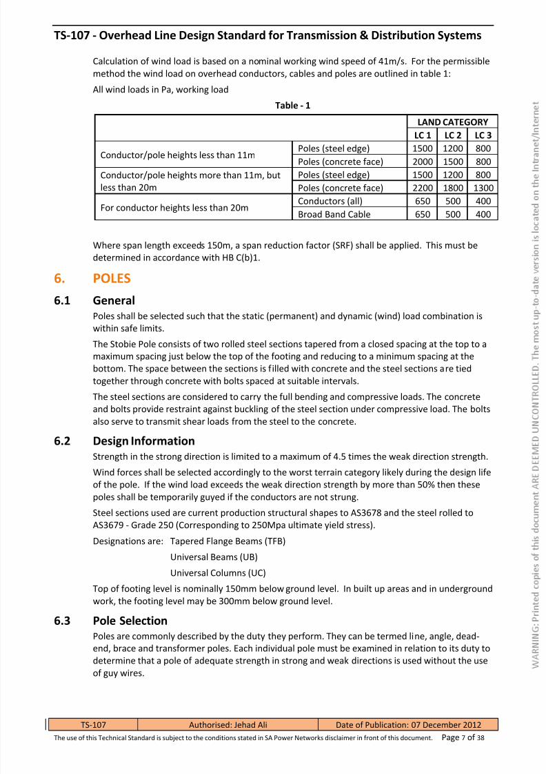
Calculation of wind load is based on a nominal working wind speed of 41m/s. For the permissible
method the wind load on overhead conductors, cables and poles are outlined in table 1:
All wind loads in Pa, working load
Table - 1
LAND CATEGORY
LC 1 LC 2 LC 3
Conductor/pole heights less than 11mPoles (steel edge) 1500 1200 800
Poles (concrete face) 2000 1500 800
Conductor/pole heights more than 11m, but
less than 20m
Poles (steel edge) 1500 1200 800
Poles (concrete face) 2200 1800 1300
For conductor heights less than 20mConductors (all) 650 500 400
Broad Band Cable 650 500 400
Where span length exceeds 150m, a span reduction factor (SRF) shall be applied. This must be
determined in accordance with HB C(b)1.
6. POLES
6.1 General
Poles shall be selected such that the static (permanent) and dynamic (wind) load combination is
within safe limits.
The Stobie Pole consists of two rolled steel sections tapered from a closed spacing at the top to a
maximum spacing just below the top of the footing and reducing to a minimum spacing at the
bottom. The space between the sections is filled with concrete and the steel sections are tied
together through concrete with bolts spaced at suitable intervals.
The steel sections are considered to carry the full bending and compressive loads. The concrete
and bolts provide restraint against buckling of the steel section under compressive load. The boltsalso serve to transmit shear loads from the steel to the concrete.
6.2 Design Information
Strength in the strong direction is limited to a maximum of 4.5 times the weak direction strength.
Wind forces shall be selected accordingly to the worst terrain category likely during the design life
of the pole. If the wind load exceeds the weak direction strength by more than 50% then these
poles shall be temporarily guyed if the conductors are not strung.
Steel sections used are current production structural shapes to AS3678 and the steel rolled to
AS3679 - Grade 250 (Corresponding to 250Mpa ultimate yield stress).
Designations are: Tapered Flange Beams (TFB)Universal Beams (UB)
Universal Columns (UC)
Top of footing level is nominally 150mm below ground level. In built up areas and in underground
work, the footing level may be 300mm below ground level.
6.3 Pole SelectionPoles are commonly described by the duty they perform. They can be termed line, angle, dead-
end, brace and transformer poles. Each individual pole must be examined in relation to its duty to
determine that a pole of adequate strength in strong and weak directions is used without the use
of guy wires.
8/12/2019 Aus Trans Std
http://slidepdf.com/reader/full/aus-trans-std 8/33
TS-107 - Overhead Line Design Standard for Transmission & Distribution Systems
TS-107 Authorised: Jehad Ali Date of Publication: 07 December 2012
The use of this Technical Standard is subject to the conditions stated in SA Power Networks disclaimer in front of this document. Page 8 of 38
6.4 Loading Parameters on PolesThe design loadings reflected to the pole top in both strong and weak direction, should not
exceed the strength of the pole in either direction.
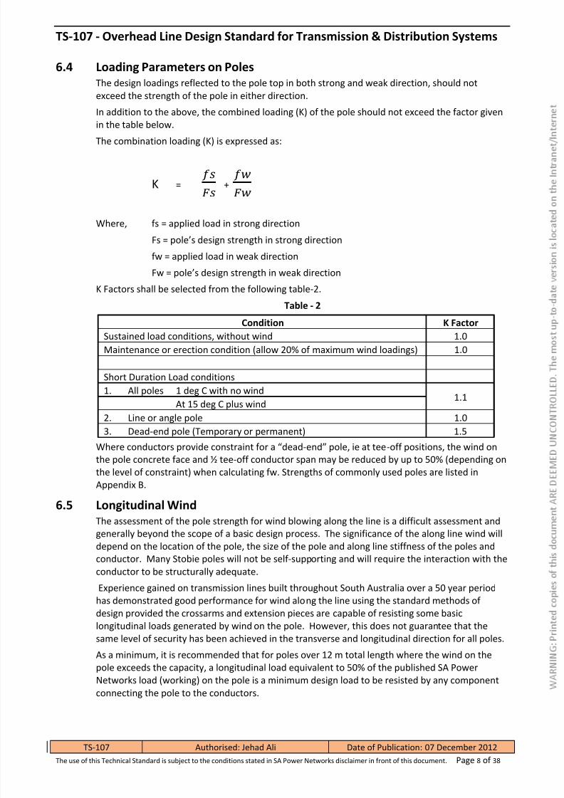
In addition to the above, the combined loading (K) of the pole should not exceed the factor given
in the table below.
The combination loading (K) is expressed as:
K = +
Where, fs = applied load in strong direction
Fs = pole’s design strength in strong direction
fw = applied load in weak direction
Fw = pole’s design strength in weak direction
K Factors shall be selected from the following table-2.
Table - 2
Condition K Factor
Sustained load conditions, without wind 1.0
Maintenance or erection condition (allow 20% of maximum wind loadings) 1.0
Short Duration Load conditions
1. All poles 1 deg C with no wind1.1
At 15 deg C plus wind
2. Line or angle pole 1.03. Dead-end pole (Temporary or permanent) 1.5
Where conductors provide constraint for a “dead-end” pole, ie at tee-off positions, the wind on
the pole concrete face and ½ tee-off conductor span may be reduced by up to 50% (depending on
the level of constraint) when calculating fw. Strengths of commonly used poles are listed in
Appendix B.
6.5 Longitudinal WindThe assessment of the pole strength for wind blowing along the line is a difficult assessment and
generally beyond the scope of a basic design process. The significance of the along line wind will
depend on the location of the pole, the size of the pole and along line stiffness of the poles and
conductor. Many Stobie poles will not be self-supporting and will require the interaction with theconductor to be structurally adequate.
Experience gained on transmission lines built throughout South Australia over a 50 year period
has demonstrated good performance for wind along the line using the standard methods of
design provided the crossarms and extension pieces are capable of resisting some basic
longitudinal loads generated by wind on the pole. However, this does not guarantee that the
same level of security has been achieved in the transverse and longitudinal direction for all poles.
As a minimum, it is recommended that for poles over 12 m total length where the wind on the
pole exceeds the capacity, a longitudinal load equivalent to 50% of the published SA Power
Networks load (working) on the pole is a minimum design load to be resisted by any component
connecting the pole to the conductors.
8/12/2019 Aus Trans Std
http://slidepdf.com/reader/full/aus-trans-std 9/33
TS-107 - Overhead Line Design Standard for Transmission & Distribution Systems
TS-107 Authorised: Jehad Ali Date of Publication: 07 December 2012
The use of this Technical Standard is subject to the conditions stated in SA Power Networks disclaimer in front of this document. Page 9 of 38
This load should be shared between each of the conductors. This along line load is not required
to be applied to the pole to determine adequacy in the direction along the line. For poles where
the conductor does not deviate, the pole capacity need only be checked against strength in the
transverse (strong) direction provided the ratio of strong to weak strength does not exceed 4.5 to
1.
The designer should give individual consideration to every pole and make some assessment on
the effect of wind in the direction along the line and how the pole is supported. Use of a previoussuccessful standard pole/conductor/crossarm/span length arrangement is considered a
reasonable assessment criterion for a basic line design. SA Power Networks may request that the
design is given a more sophisticated assessment by an independent designer.
6.6 Standard Location of PolesPoles shall be located in positions which meet the requirements of Network Directive ND-P1
(re-printed in Appendix C)
7. FOOTINGS
7.1
GeneralPoles shall be selected such that they can withstand loads without the assistance of guy wires.
The footing selection shall also be based on the correct assessment of the soil type.
7.2 Soil TypesSoils are grouped into three classes, A, B, and C as follows;
Class A Gravel, compacted sand and rock soils not subject to large variations in volume with
moisture content, which offer appreciable resistance to boring and which remain
stable after boring.
Note: If the excavation is in rock, the hole should be just large enough to take the
pole at the recommended depth, and no reinforcement is necessary in the concrete.
Class B Soils subject to large variations in volume with changing moisture content. Soils
which offer little cohesion, ie clay.
Class C Low bearing soil. Requires caisson to support sides during excavation. Examples are
swamps, saturated soil and drift sands.
7.3 Footing TypesThe footing type shall be selected from the SA Power Networks Construction Manual (Drawing E-
1800 series). Alternative footing arrangements may be used if certified by an appropriately
qualified civil engineer.
The types are:
1. Full strength
a. In Situ
b. Two Block
c. Cylindrical
d. Deep Type
2. Unformed Footings
The “Unformed” footing is acceptable where it can be certified by an appropriately qualified
civil engineer that loads on the pole will not exceed the strength of the pole and cause
movement.
An unformed footing may be used when :
a. a pole is not to be loaded at more than 50% of its strong direction strength, orb. exceed half the design factor, ie 1.5 for terminal pole equates to 0.75.
An unformed footing may NOT be used when for a terminal pole.
8/12/2019 Aus Trans Std
http://slidepdf.com/reader/full/aus-trans-std 10/33
TS-107 - Overhead Line Design Standard for Transmission & Distribution Systems
TS-107 Authorised: Jehad Ali Date of Publication: 07 December 2012
The use of this Technical Standard is subject to the conditions stated in SA Power Networks disclaimer in front of this document. Page 10 of 38
7.4 MaterialsConcrete for footings shall have a minimum compressive strength of 12 MPa at 7 days and
20 MPa at 28 days.
A reinforcing cage must be used for all transmission poles.
7.5 FormersFormers shall be used for cored footings. Formers are numbered on size order from 0 to U5,
where 0 is the smallest. Refer to SA Power Networks WC series drawings for former dimensions.
7.6 Footing OrientationAll pole footings shall be orientated correctly in relation to the centre line of the mains, and shall
be positioned so that the pole will have the direction of the resultant forces acting along the
strong direction of the pole.
8. CONDUCTORS
8.1 Definitions for Conductor Tensions
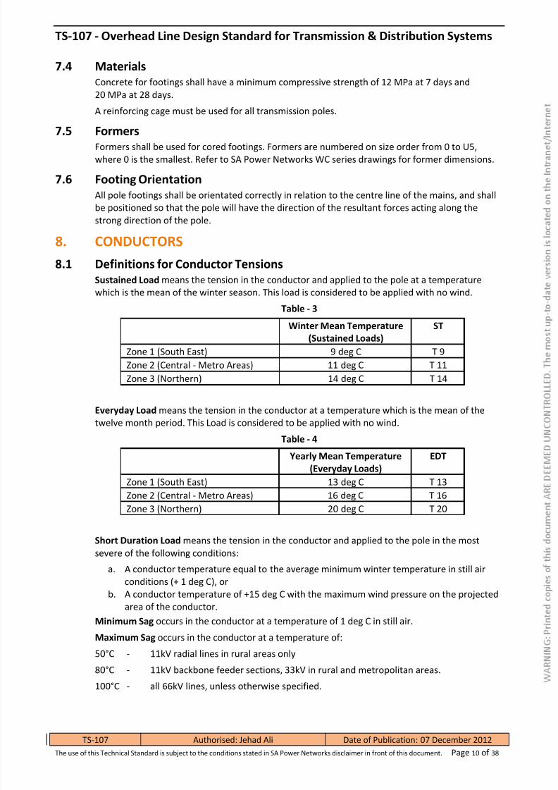
Sustained Load means the tension in the conductor and applied to the pole at a temperaturewhich is the mean of the winter season. This load is considered to be applied with no wind.
Table - 3
Winter Mean Temperature
(Sustained Loads)
ST
Zone 1 (South East) 9 deg C T 9
Zone 2 (Central - Metro Areas) 11 deg C T 11
Zone 3 (Northern) 14 deg C T 14
Everyday Load means the tension in the conductor at a temperature which is the mean of the
twelve month period. This Load is considered to be applied with no wind.
Table - 4
Yearly Mean Temperature
(Everyday Loads)
EDT
Zone 1 (South East) 13 deg C T 13
Zone 2 (Central - Metro Areas) 16 deg C T 16
Zone 3 (Northern) 20 deg C T 20
Short Duration Load means the tension in the conductor and applied to the pole in the most
severe of the following conditions:a. A conductor temperature equal to the average minimum winter temperature in still air
conditions (+ 1 deg C), or
b. A conductor temperature of +15 deg C with the maximum wind pressure on the projected
area of the conductor.
Minimum Sag occurs in the conductor at a temperature of 1 deg C in still air.
Maximum Sag occurs in the conductor at a temperature of:
50°C - 11kV radial lines in rural areas only
80°C - 11kV backbone feeder sections, 33kV in rural and metropolitan areas.
100°C - all 66kV lines, unless otherwise specified.
8/12/2019 Aus Trans Std
http://slidepdf.com/reader/full/aus-trans-std 11/33
TS-107 - Overhead Line Design Standard for Transmission & Distribution Systems
TS-107 Authorised: Jehad Ali Date of Publication: 07 December 2012
The use of this Technical Standard is subject to the conditions stated in SA Power Networks disclaimer in front of this document. Page 11 of 38
8.2 GeneralVibration induced into the line shall be limited by careful selection of a tension at which the
conductor operates for the majority of its design life to ensure that the fatigue endurance limit of
the conductor wires is not reached.
8.3 TensionThe design conductor tension under the everyday load condition is that the horizontal tension
shall be no greater than the percentage of its calculated breaking load as derived from HB C(b)1.
Under the short duration load, the tangential tension in the conductor should not exceed 50% of
its calculated breaking load.
It must be stressed that this is a maximum tension which should be used to avoid damage to the
conductor over its expected service life. Lesser tensions may be used accordingly to pole
capacities or other considerations. Design constants for bare conductors are contained in
Appendix A
8.4 Side Swing
All designs must include a check to ensure that the conductor will not swing, under the influenceof wind, outside the requirements of the Electricity Act and Regulations. This design shall be
checked at the conditions stated in clause 2 and 3, eg for rural application in terrain category 2,
- T50 + 500pa wind.
8.5 Measurements of As-Built ConditionSA Power Networks’ Compliance Inspector shall have at all reasonable times access to the work
site, and shall have the power at all reasonable times, to inspect, examine, and test materials and
workmanship of the works during its manufacture or installation.
Measurement Sheets are to be completed by the Contractor throughout the progress of the
works. The Measurement Sheets shall be submitted with the Certificate of Practical Completion.
Measurement Sheets shall be in accordance with Appendix E. Where tests are performed i.e.earth stake resistance readings, they shall be recorded in accordance with the Testing Standard
(TS 105) and submitted with the Certificate of Practical Completion.
9. POLE TOP CONSTRUCTIONS
9.1 Pole top AssembliesPole top assemblies shall be selected and constructed in accordance with the relevant E-Drawings.
Only arrangements including combination arrangements illustrated in the E-Drawings are
acceptable.
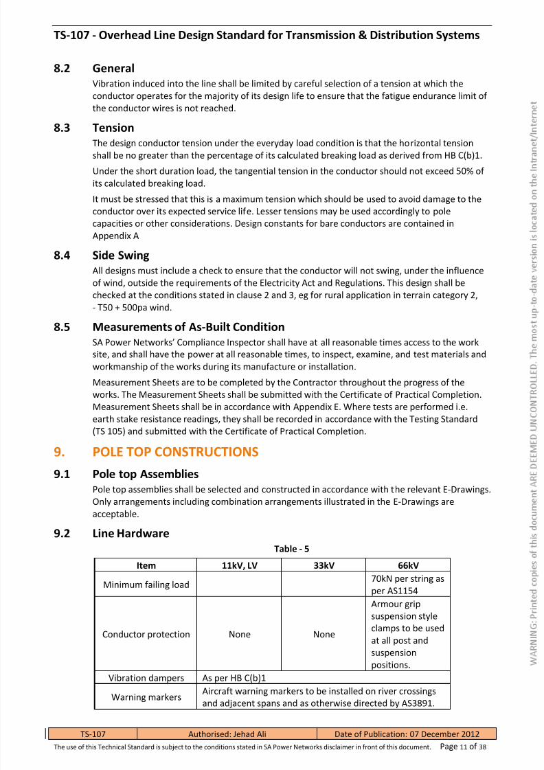
9.2 Line Hardware
Table - 5
Item 11kV, LV 33kV 66kV
Minimum failing load70kN per string as
per AS1154
Conductor protection None None
Armour grip
suspension style
clamps to be used
at all post and
suspension
positions.
Vibration dampers As per HB C(b)1
Warning markersAircraft warning markers to be installed on river crossings
and adjacent spans and as otherwise directed by AS3891.
8/12/2019 Aus Trans Std
http://slidepdf.com/reader/full/aus-trans-std 12/33
TS-107 - Overhead Line Design Standard for Transmission & Distribution Systems
TS-107 Authorised: Jehad Ali Date of Publication: 07 December 2012
The use of this Technical Standard is subject to the conditions stated in SA Power Networks disclaimer in front of this document. Page 12 of 38
9.3 Network Directive ND J4All new power lines constructed must conform to the Network Directive, ND J4: ‘Construction of
New Power Lines’. A copy of ND J4 can be found in Appendix D.
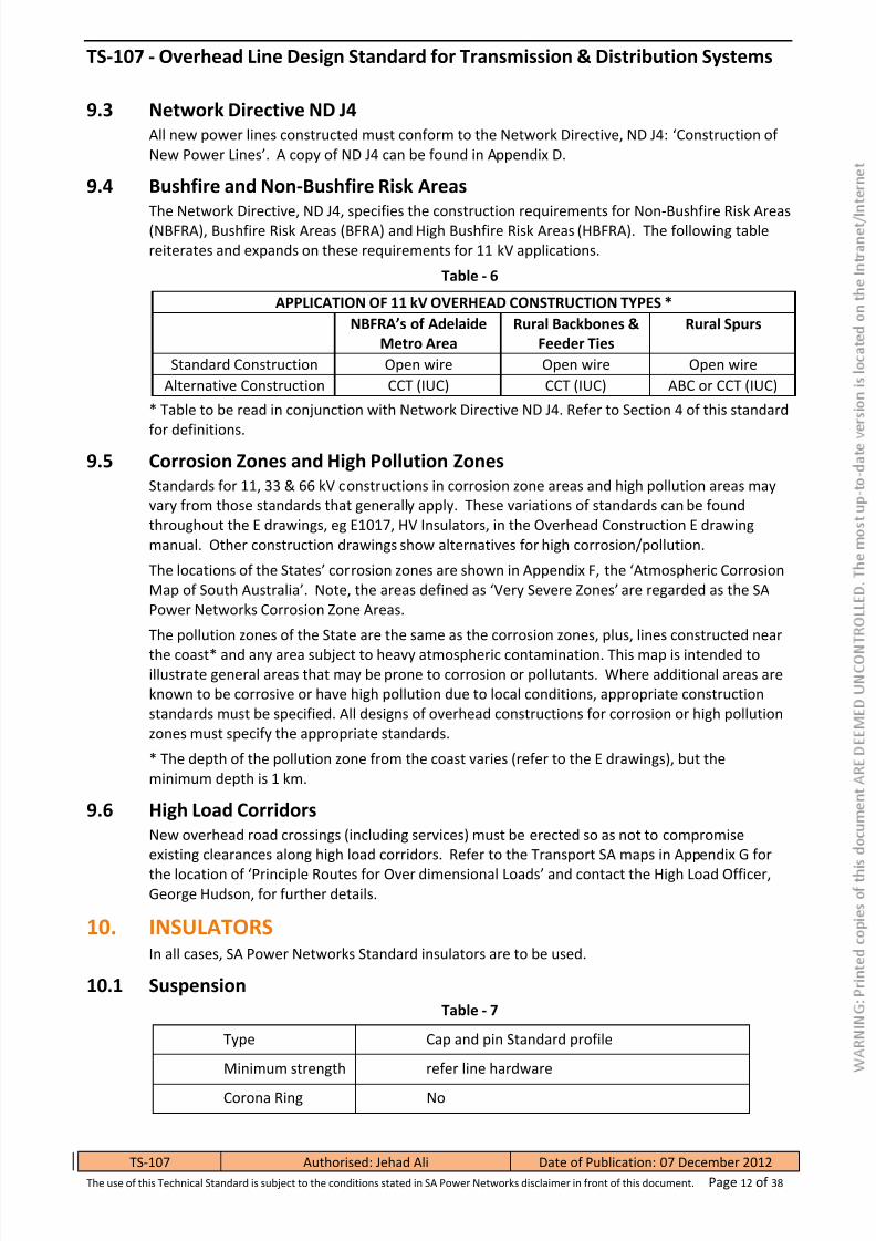
9.4 Bushfire and Non-Bushfire Risk Areas
The Network Directive, ND J4, specifies the construction requirements for Non-Bushfire Risk Areas(NBFRA), Bushfire Risk Areas (BFRA) and High Bushfire Risk Areas (HBFRA). The following table
reiterates and expands on these requirements for 11 kV applications.
Table - 6
APPLICATION OF 11 kV OVERHEAD CONSTRUCTION TYPES *
NBFRA’s of Adelaide
Metro Area
Rural Backbones &
Feeder Ties
Rural Spurs
Standard Construction Open wire Open wire Open wire
Alternative Construction CCT (IUC) CCT (IUC) ABC or CCT (IUC)
* Table to be read in conjunction with Network Directive ND J4. Refer to Section 4 of this standard
for definitions.
9.5 Corrosion Zones and High Pollution ZonesStandards for 11, 33 & 66 kV constructions in corrosion zone areas and high pollution areas may
vary from those standards that generally apply. These variations of standards can be found
throughout the E drawings, eg E1017, HV Insulators, in the Overhead Construction E drawing
manual. Other construction drawings show alternatives for high corrosion/pollution.
The locations of the States’ corrosion zones are shown in Appendix F, the ‘Atmospheric Corrosion
Map of South Australia’. Note, the areas defined as ‘Very Severe Zones’ are regarded as the SA
Power Networks Corrosion Zone Areas.
The pollution zones of the State are the same as the corrosion zones, plus, lines constructed near
the coast* and any area subject to heavy atmospheric contamination. This map is intended toillustrate general areas that may be prone to corrosion or pollutants. Where additional areas are
known to be corrosive or have high pollution due to local conditions, appropriate construction
standards must be specified. All designs of overhead constructions for corrosion or high pollution
zones must specify the appropriate standards.
* The depth of the pollution zone from the coast varies (refer to the E drawings), but the
minimum depth is 1 km.
9.6 High Load CorridorsNew overhead road crossings (including services) must be erected so as not to compromise
existing clearances along high load corridors. Refer to the Transport SA maps in Appendix G for
the location of ‘Principle Routes for Over dimensional Loads’ and contact the High Load Officer,
George Hudson, for further details.
10. INSULATORSIn all cases, SA Power Networks Standard insulators are to be used.
10.1 SuspensionTable - 7
Type Cap and pin Standard profile
Minimum strength refer line hardware
Corona Ring No
8/12/2019 Aus Trans Std
http://slidepdf.com/reader/full/aus-trans-std 13/33
TS-107 - Overhead Line Design Standard for Transmission & Distribution Systems
TS-107 Authorised: Jehad Ali Date of Publication: 07 December 2012
The use of this Technical Standard is subject to the conditions stated in SA Power Networks disclaimer in front of this document. Page 13 of 38
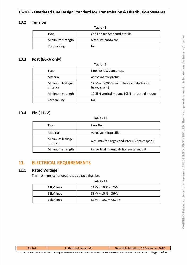
10.2 TensionTable - 8
Type Cap and pin Standard profile
Minimum strength refer line hardware
Corona Ring No
10.3 Post (66kV only)Table - 9
Type Line Post AS Clamp top,
Material Aerodynamic profile
Minimum leakage
distance
1780mm (2080mm for large conductors &
heavy spans)
Minimum strength 12.5kN vertical mount, 19kN horizontal mount
Corona Ring No
10.4 Pin (11kV)Table - 10
Type Line Pin,
Material Aerodynamic profile
Minimum leakagedistance
mm (mm for large conductors & heavy spans)
Minimum strength kN vertical mount, kN horizontal mount
11. ELECTRICAL REQUIREMENTS
11.1 Rated Voltage
The maximum continuous rated voltage shall be:
Table - 11
11kV lines 11kV + 10 % = 12kV
33kV lines 33kV + 10 % = 36kV
66kV lines 66kV + 10% = 72.6kV
8/12/2019 Aus Trans Std
http://slidepdf.com/reader/full/aus-trans-std 14/33
TS-107 - Overhead Line Design Standard for Transmission & Distribution Systems
TS-107 Authorised: Jehad Ali Date of Publication: 07 December 2012
The use of this Technical Standard is subject to the conditions stated in SA Power Networks disclaimer in front of this document. Page 14 of 38
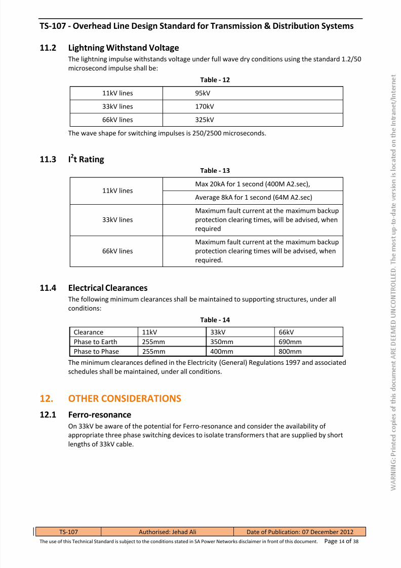
11.2 Lightning Withstand VoltageThe lightning impulse withstands voltage under full wave dry conditions using the standard 1.2/50
microsecond impulse shall be:
Table - 12
11kV lines 95kV
33kV lines 170kV
66kV lines 325kV
The wave shape for switching impulses is 250/2500 microseconds.
11.3 I2t Rating
Table - 13
11kV linesMax 20kA for 1 second (400M A2.sec),
Average 8kA for 1 second (64M A2.sec)
33kV lines
Maximum fault current at the maximum backup
protection clearing times, will be advised, when
required
66kV lines
Maximum fault current at the maximum backup
protection clearing times will be advised, when
required.
11.4 Electrical Clearances
The following minimum clearances shall be maintained to supporting structures, under allconditions:
Table - 14
Clearance 11kV 33kV 66kV
Phase to Earth 255mm 350mm 690mm
Phase to Phase 255mm 400mm 800mm
The minimum clearances defined in the Electricity (General) Regulations 1997 and associated
schedules shall be maintained, under all conditions.
12. OTHER CONSIDERATIONS12.1 Ferro-resonance
On 33kV be aware of the potential for Ferro-resonance and consider the availability of
appropriate three phase switching devices to isolate transformers that are supplied by short
lengths of 33kV cable.
8/12/2019 Aus Trans Std
http://slidepdf.com/reader/full/aus-trans-std 15/33
TS-107 - Overhead Line Design Standard for Transmission & Distribution Systems
TS-107 Authorised: Jehad Ali Date of Publication: 07 December 2012
The use of this Technical Standard is subject to the conditions stated in SA Power Networks disclaimer in front of this document. Page 15 of 38
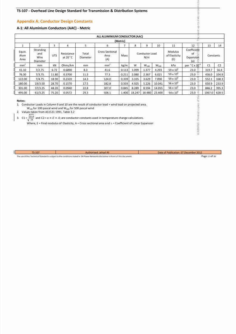
Appendix A: Conductor Design Constants
A-1: All Aluminium Conductors (AAC) - Metric
ALL ALUMINIUM CONDUCTOR (AAC)
(Metric)
1 2 3 4 5 6 7 8 9 10 11 12 13 14
Equiv.
Alum
Area
Stranding
and
WireDiameter
UTSResistance
at 20°C
Total
Diameter
Cross Sectional
Area
(A)
MassConductor Load
N/m
Modulus
of Elasticity
(E)
Coefficient
of
Expansion(a)
Constants
mm2 mm kN Ohms/km mm mm2 kg/m W W100 W500 kPa per °C x 10-6
C1 C2
41.10 7/2.75 6.72 0.6890 8.3 41.6 0.113 1.099 1.377 4.293 59 x 106 23.0 319.7 56.4
76.30 7/3.75 11.80 0.3700 11.3 77.3 0.211 2.080 2.367 6.021 59 x 106 23.0 436.0 104.9
122.00 7/4.75 18.90 0.2320 14.3 124.0 0.339 3.335 3.629 7.890 59 x 106 23.0 552.1 168.3
180.00 19/3.50 28.70 0.1570 17.5 182.8 0.503 4.925 5.226 10.041 56 x 106 23.0 650.9 233.9
301.00 37/3.25 48.20 0.0940 22.8 307.0 0.845 8.289 8.594 14.055 56 x 106 23.0 846.2 395.3
495.00 61/3.25 75.20 0.0572 29.3 506.1 1.400 18.247 18.480 23.400 54 x 106 23.0 1067.0 628.5
Notes:
1. Conductor Loads in Column 9 and 10 are the result of conductor load + wind load on projected area.
W100 for 100 pascal wind and W500 for 500 pascal wind
2. Values taken from AS1531 1991, Table 3.2
3. C1 = and C2 = ; are conductor constants used in temperature change calculations.
Where, E = Final modulus of Elasticity, A = Cross sectional area and a = Coefficient of Linear Expansion
8/12/2019 Aus Trans Std
http://slidepdf.com/reader/full/aus-trans-std 16/33
TS-107 - Overhead Line Design Standard for Transmission & Distribution Systems
TS-107 Authorised: Jehad Ali Date of Publication: 07 December 2012
The use of this Technical Standard is subject to the conditions stated in SA Power Networks disclaimer in front of this document. Page 16 of 38
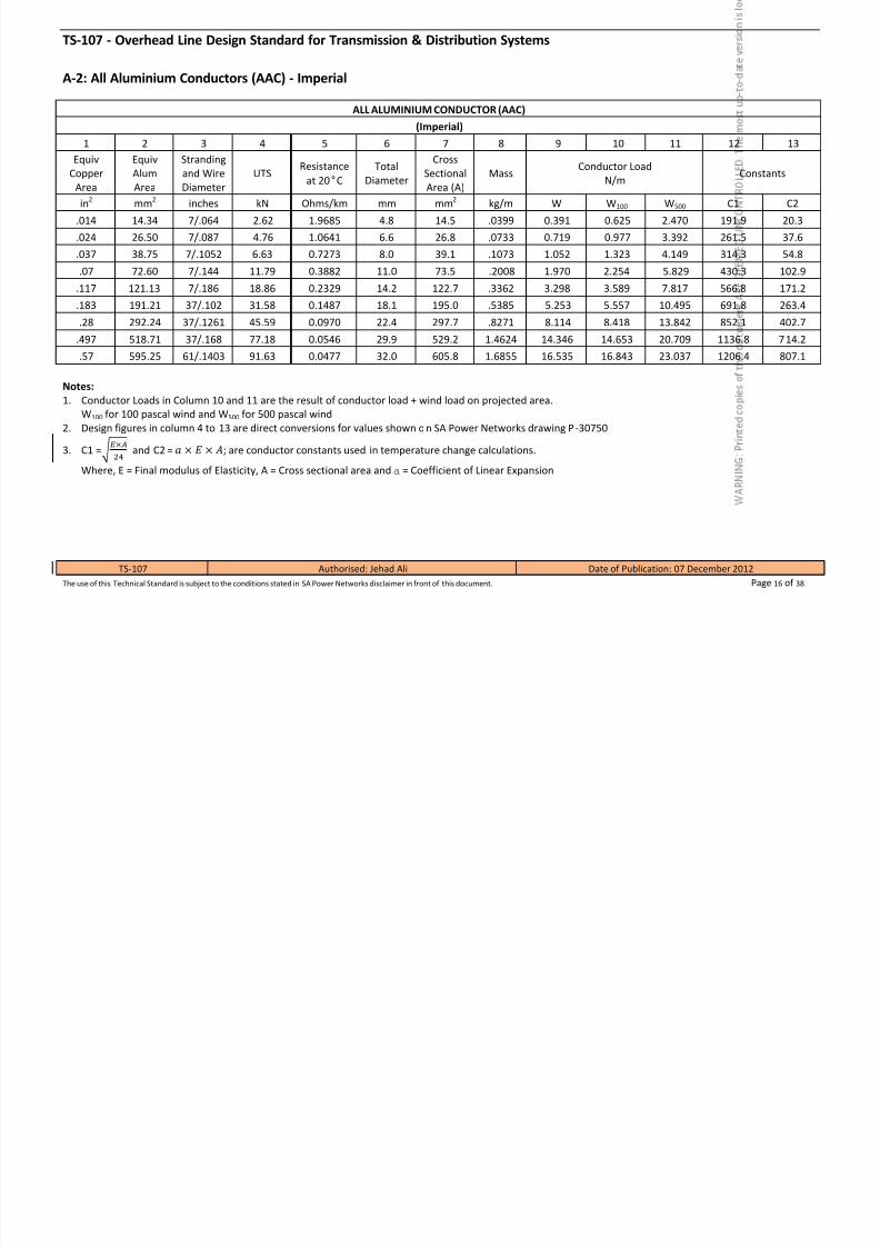
A-2: All Aluminium Conductors (AAC) - Imperial
ALL ALUMINIUM CONDUCTOR (AAC)
(Imperial)
1 2 3 4 5 6 7 8 9 10 11 12 13
Equiv
Copper
Area
Equiv
Alum
Area
Stranding
and Wire
Diameter
UTSResistance
at 20°C
Total
Diameter
Cross
Sectional
Area (A)
MassConductor Load
N/mConstants
in2 mm
2 inches kN Ohms/km mm mm
2 kg/m W W100 W500 C1 C2
.014 14.34 7/.064 2.62 1.9685 4.8 14.5 .0399 0.391 0.625 2.470 191.9 20.3
.024 26.50 7/.087 4.76 1.0641 6.6 26.8 .0733 0.719 0.977 3.392 261.5 37.6
.037 38.75 7/.1052 6.63 0.7273 8.0 39.1 .1073 1.052 1.323 4.149 314.3 54.8
.07 72.60 7/.144 11.79 0.3882 11.0 73.5 .2008 1.970 2.254 5.829 430.3 102.9
.117 121.13 7/.186 18.86 0.2329 14.2 122.7 .3362 3.298 3.589 7.817 566.8 171.2
.183 191.21 37/.102 31.58 0.1487 18.1 195.0 .5385 5.253 5.557 10.495 691.8 263.4
.28 292.24 37/.1261 45.59 0.0970 22.4 297.7 .8271 8.114 8.418 13.842 852.1 402.7
.497 518.71 37/.168 77.18 0.0546 29.9 529.2 1.4624 14.346 14.653 20.709 1136.8 714.2
.57 595.25 61/.1403 91.63 0.0477 32.0 605.8 1.6855 16.535 16.843 23.037 1206.4 807.1
Notes:
1. Conductor Loads in Column 10 and 11 are the result of conductor load + wind load on projected area.
W100 for 100 pascal wind and W500 for 500 pascal wind
2. Design figures in column 4 to 13 are direct conversions for values shown on SA Power Networks drawing P-30750
3. C1 = and C2 = ; are conductor constants used in temperature change calculations.
Where, E = Final modulus of Elasticity, A = Cross sectional area and a = Coefficient of Linear Expansion
8/12/2019 Aus Trans Std
http://slidepdf.com/reader/full/aus-trans-std 17/33
TS-107 - Overhead Line Design Standard for Transmission & Distribution Systems
TS-107 Authorised: Jehad Ali Date of Publication: 07 December 2012
The use of this Technical Standard is subject to the conditions stated in SA Power Networks disclaimer in front of this document. Page 17 of 38
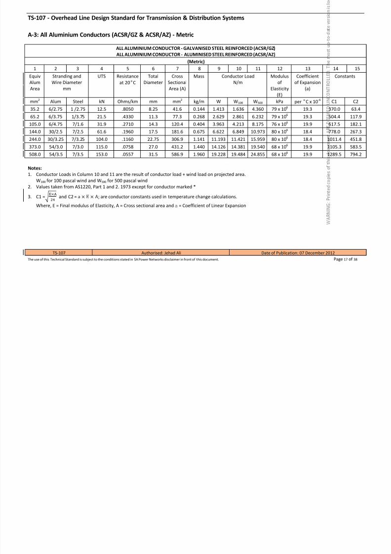
A-3: All Aluminium Conductors (ACSR/GZ & ACSR/AZ) - Metric
ALL ALUMINIUM CONDUCTOR - GALVANISED STEEL REINFORCED (ACSR/GZ)
ALL ALUMINIUM CONDUCTOR - ALUMINISED STEEL REINFORCED (ACSR/AZ)
(Metric)
1 2 3 4 5 6 7 8 9 10 11 12 13 14 15
Equiv
Alum
Area
Stranding and
Wire Diameter
mm
UTS Resistance
at 20°C
Total
Diameter
Cross
Sectional
Area (A)
Mass Conductor Load
N/m
Modulus
of
Elasticity
(E)
Coefficient
of Expansion
(a)
Constants
mm2 Alum Steel kN Ohms/km mm mm2 kg/m W W100 W500 kPa per °C x 10-6 C1 C2
35.2 6/2.75 1 /2.75 12.5 .8050 8.25 41.6 0.144 1.413 1.636 4.360 79 x 106 19.3 370.0 63.4
65.2 6/3.75 1/3.75 21.5 .4330 11.3 77.3 0.268 2.629 2.861 6.232 79 x 106 19.3 504.4 117.9
105.0 6/4.75 7/1.6 31.9 .2710 14.3 120.4 0.404 3.963 4.213 8.175 76 x 106 19.9 617.5 182.1
144.0 30/2.5 7/2.5 61.6 .1960 17.5 181.6 0.675 6.622 6.849 10.973 80 x 106 18.4 778.0 267.3
244.0 30/3.25 7/3.25 104.0 .1160 22.75 306.9 1.141 11.193 11.421 15.959 80 x 106 18.4 1011.4 451.8
373.0 54/3.0 7/3.0 115.0 .0758 27.0 431.2 1.440 14.126 14.381 19.540 68 x 106 19.9 1105.3 583.5
508.0 54/3.5 7/3.5 153.0 .0557 31.5 586.9 1.960 19.228 19.484 24.855 68 x 106 19.9 1289.5 794.2
Notes:
1. Conductor Loads in Column 10 and 11 are the result of conductor load + wind load on projected area.
W100 for 100 pascal wind and W500 for 500 pascal wind
2. Values taken from AS1220, Part 1 and 2. 1973 except for conductor marked *
3. C1 = and C2 = ; are conductor constants used in temperature change calculations.
Where, E = Final modulus of Elasticity, A = Cross sectional area and a = Coefficient of Linear Expansion
8/12/2019 Aus Trans Std
http://slidepdf.com/reader/full/aus-trans-std 18/33
TS-107 - Overhead Line Design Standard for Transmission & Distribution Systems
TS-107 Authorised: Jehad Ali Date of Publication: 07 December 2012
The use of this Technical Standard is subject to the conditions stated in SA Power Networks disclaimer in front of this document. Page 18 of 38
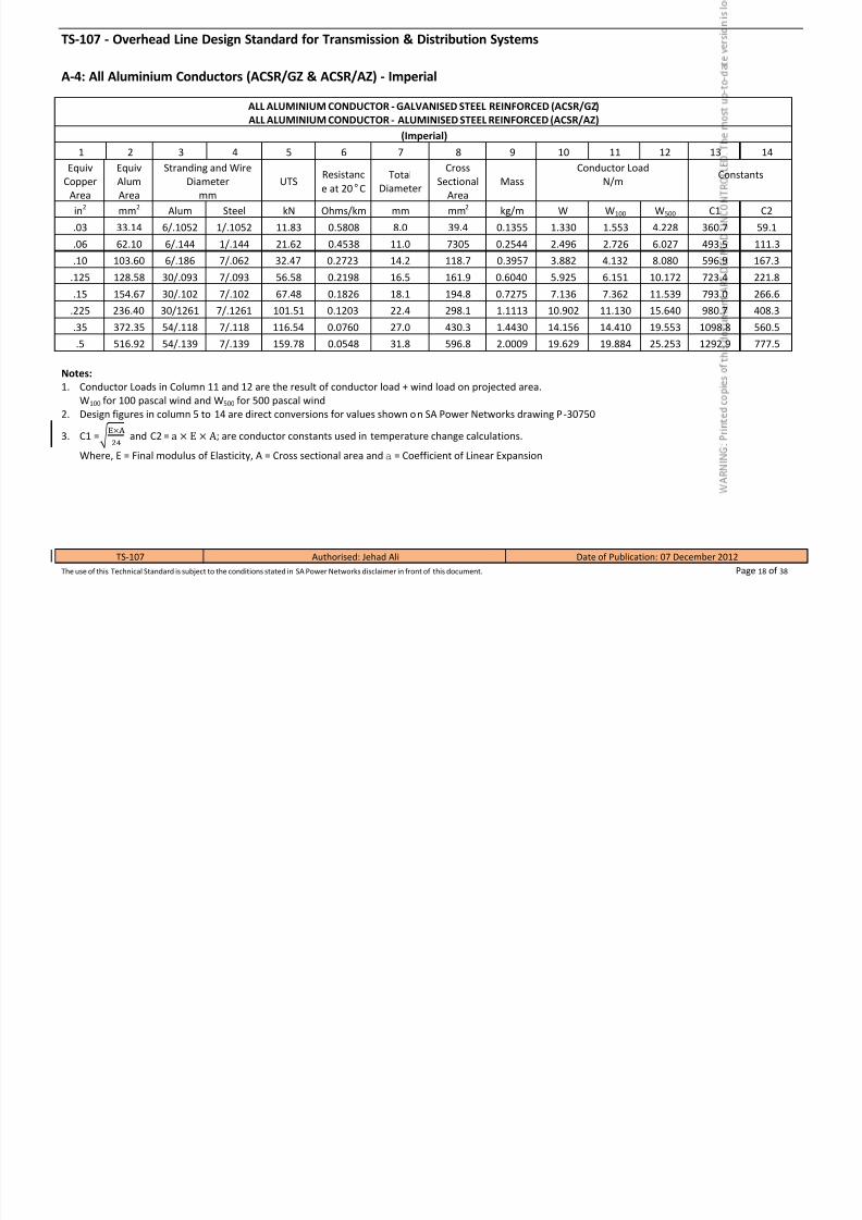
A-4: All Aluminium Conductors (ACSR/GZ & ACSR/AZ) - Imperial
ALL ALUMINIUM CONDUCTOR - GALVANISED STEEL REINFORCED (ACSR/GZ)
ALL ALUMINIUM CONDUCTOR - ALUMINISED STEEL REINFORCED (ACSR/AZ)
(Imperial)
1 2 3 4 5 6 7 8 9 10 11 12 13 14
Equiv
Copper
Area
Equiv
Alum
Area
Stranding and Wire
Diameter
mm
UTSResistanc
e at 20°C
Total
Diameter
Cross
Sectional
Area
Mass
Conductor Load
N/mConstants
in2
mm2
Alum Steel kN Ohms/km mm mm2
kg/m W W100 W500 C1 C2.03 33.14 6/.1052 1/.1052 11.83 0.5808 8.0 39.4 0.1355 1.330 1.553 4.228 360.7 59.1
.06 62.10 6/.144 1/.144 21.62 0.4538 11.0 7305 0.2544 2.496 2.726 6.027 493.5 111.3
.10 103.60 6/.186 7/.062 32.47 0.2723 14.2 118.7 0.3957 3.882 4.132 8.080 596.9 167.3
.125 128.58 30/.093 7/.093 56.58 0.2198 16.5 161.9 0.6040 5.925 6.151 10.172 723.4 221.8
.15 154.67 30/.102 7/.102 67.48 0.1826 18.1 194.8 0.7275 7.136 7.362 11.539 793.0 266.6
.225 236.40 30/1261 7/.1261 101.51 0.1203 22.4 298.1 1.1113 10.902 11.130 15.640 980.7 408.3
.35 372.35 54/.118 7/.118 116.54 0.0760 27.0 430.3 1.4430 14.156 14.410 19.553 1098.8 560.5
.5 516.92 54/.139 7/.139 159.78 0.0548 31.8 596.8 2.0009 19.629 19.884 25.253 1292.9 777.5
Notes:
1. Conductor Loads in Column 11 and 12 are the result of conductor load + wind load on projected area.
W100 for 100 pascal wind and W500 for 500 pascal wind
2. Design figures in column 5 to 14 are direct conversions for values shown on SA Power Networks drawing P-30750
3. C1 = and C2 = ; are conductor constants used in temperature change calculations.
Where, E = Final modulus of Elasticity, A = Cross sectional area and a = Coefficient of Linear Expansion
8/12/2019 Aus Trans Std
http://slidepdf.com/reader/full/aus-trans-std 19/33
TS-107 - Overhead Line Design Standard for Transmission & Distribution Systems
TS-107 Authorised: Jehad Ali Date of Publication: 07 December 2012
The use of this Technical Standard is subject to the conditions stated in SA Power Networks disclaimer in front of this document. Page 19 of 38
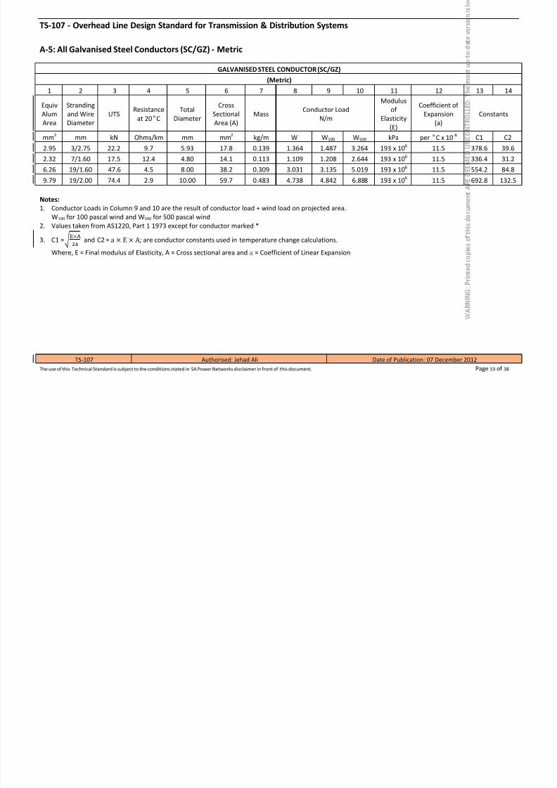
A-5: All Galvanised Steel Conductors (SC/GZ) - Metric
GALVANISED STEEL CONDUCTOR (SC/GZ)
(Metric)
1 2 3 4 5 6 7 8 9 10 11 12 13 14
Equiv
Alum
Area
Stranding
and Wire
Diameter
UTSResistance
at 20°C
Total
Diameter
Cross
Sectional
Area (A)
MassConductor Load
N/m
Modulus
of
Elasticity
(E)
Coefficient of
Expansion
(a)
Constants
mm2
mm kN Ohms/km mm mm2
kg/m W W100 W500 kPa per °C x 10-6
C1 C22.95 3/2.75 22.2 9.7 5.93 17.8 0.139 1.364 1.487 3.264 193 x 10
6 11.5 378.6 39.6
2.32 7/1.60 17.5 12.4 4.80 14.1 0.113 1.109 1.208 2.644 193 x 106 11.5 336.4 31.2
6.26 19/1.60 47.6 4.5 8.00 38.2 0.309 3.031 3.135 5.019 193 x 106 11.5 554.2 84.8
9.79 19/2.00 74.4 2.9 10.00 59.7 0.483 4.738 4.842 6.888 193 x 106 11.5 692.8 132.5
Notes:
1. Conductor Loads in Column 9 and 10 are the result of conductor load + wind load on projected area.
W100 for 100 pascal wind and W500 for 500 pascal wind
2. Values taken from AS1220, Part 1 1973 except for conductor marked *
3. C1 = and C2 = ; are conductor constants used in temperature change calculations.
Where, E = Final modulus of Elasticity, A = Cross sectional area and a = Coefficient of Linear Expansion
8/12/2019 Aus Trans Std
http://slidepdf.com/reader/full/aus-trans-std 20/33
TS-107 - Overhead Line Design Standard for Transmission & Distribution Systems
TS-107 Authorised: Jehad Ali Date of Publication: 07 December 2012
The use of this Technical Standard is subject to the conditions stated in SA Power Networks disclaimer in front of this document. Page 20 of 38
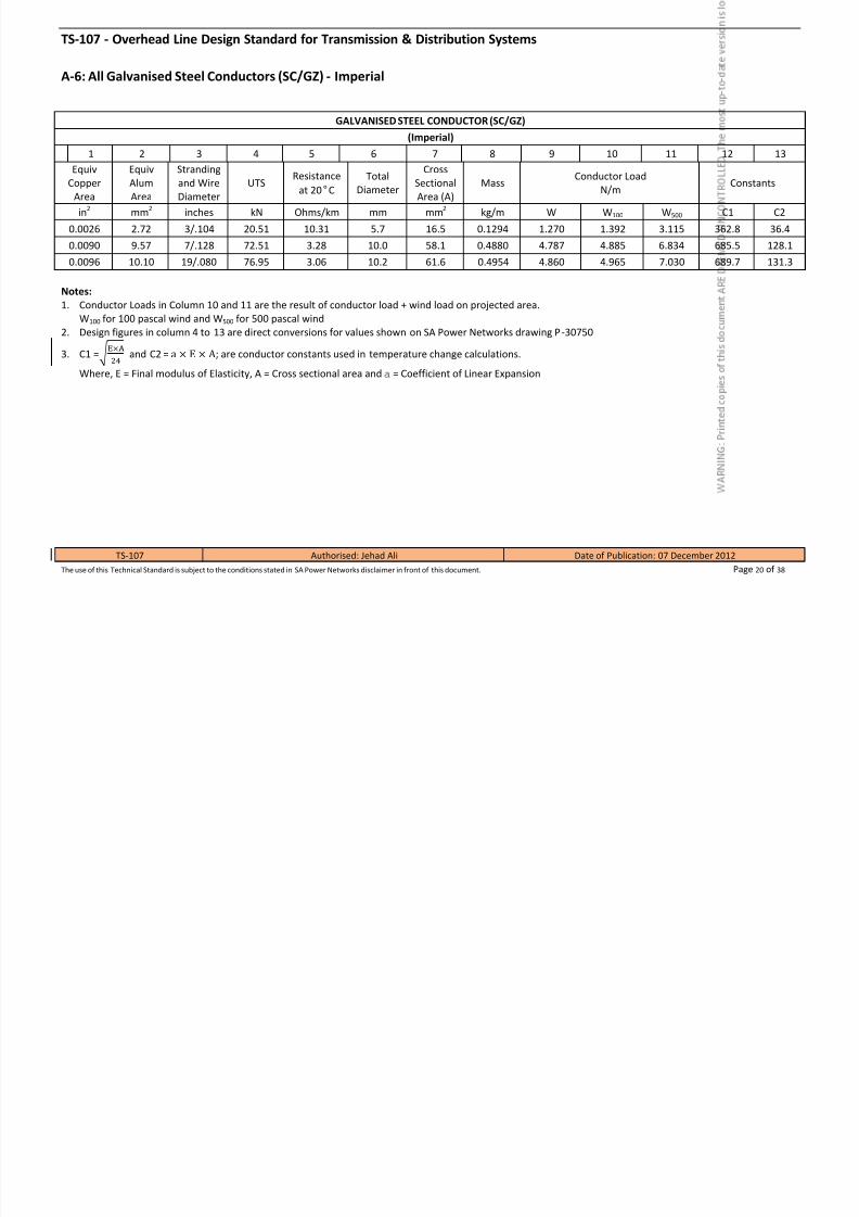
A-6: All Galvanised Steel Conductors (SC/GZ) - Imperial
GALVANISED STEEL CONDUCTOR (SC/GZ)
(Imperial)
1 2 3 4 5 6 7 8 9 10 11 12 13
Equiv
Copper
Area
Equiv
Alum
Area
Stranding
and Wire
Diameter
UTSResistance
at 20°C
Total
Diameter
Cross
Sectional
Area (A)
MassConductor Load
N/mConstants
in2
mm2
inches kN Ohms/km mm mm2
kg/m W W100 W500 C1 C20.0026 2.72 3/.104 20.51 10.31 5.7 16.5 0.1294 1.270 1.392 3.115 362.8 36.4
0.0090 9.57 7/.128 72.51 3.28 10.0 58.1 0.4880 4.787 4.885 6.834 685.5 128.1
0.0096 10.10 19/.080 76.95 3.06 10.2 61.6 0.4954 4.860 4.965 7.030 689.7 131.3
Notes:
1. Conductor Loads in Column 10 and 11 are the result of conductor load + wind load on projected area.
W100 for 100 pascal wind and W500 for 500 pascal wind
2. Design figures in column 4 to 13 are direct conversions for values shown on SA Power Networks drawing P-30750
3. C1 = and C2 = ; are conductor constants used in temperature change calculations.
Where, E = Final modulus of Elasticity, A = Cross sectional area and a = Coefficient of Linear Expansion
8/12/2019 Aus Trans Std
http://slidepdf.com/reader/full/aus-trans-std 21/33
TS-107 - Overhead Line Design Standard for Transmission & Distribution Systems
TS-107 Authorised: Jehad Ali Date of Publication: 07 December 2012
The use of this Technical Standard is subject to the conditions stated in SA Power Networks disclaimer in front of this document. Page 21 of 38
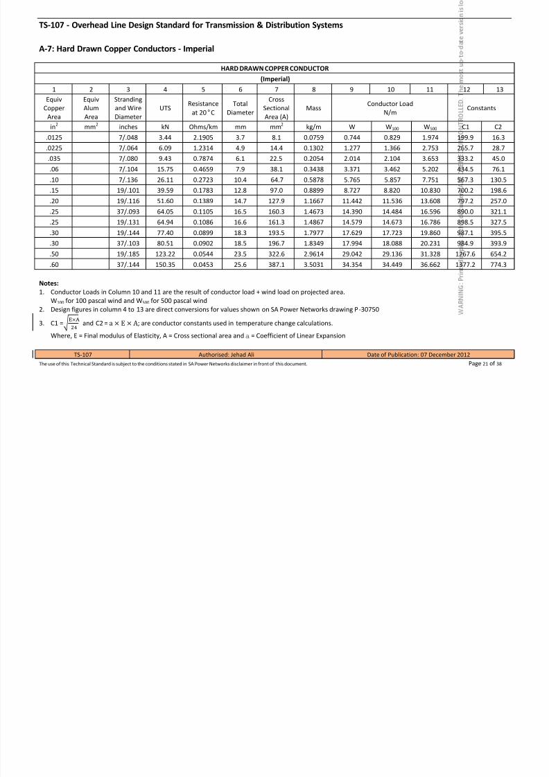
A-7: Hard Drawn Copper Conductors - Imperial
HARD DRAWN COPPER CONDUCTOR
(Imperial)
1 2 3 4 5 6 7 8 9 10 11 12 13
Equiv
Copper
Area
Equiv
Alum
Area
Stranding
and Wire
Diameter
UTSResistance
at 20°C
Total
Diameter
Cross
Sectional
Area (A)
MassConductor Load
N/mConstants
in2 mm
2 inches kN Ohms/km mm mm
2 kg/m W W100 W500 C1 C2
.0125 7/.048 3.44 2.1905 3.7 8.1 0.0759 0.744 0.829 1.974 199.9 16.3
.0225 7/.064 6.09 1.2314 4.9 14.4 0.1302 1.277 1.366 2.753 265.7 28.7
.035 7/.080 9.43 0.7874 6.1 22.5 0.2054 2.014 2.104 3.653 333.2 45.0
.06 7/.104 15.75 0.4659 7.9 38.1 0.3438 3.371 3.462 5.202 434.5 76.1
.10 7/.136 26.11 0.2723 10.4 64.7 0.5878 5.765 5.857 7.751 567.3 130.5
.15 19/.101 39.59 0.1783 12.8 97.0 0.8899 8.727 8.820 10.830 700.2 198.6
.20 19/.116 51.60 0.1389 14.7 127.9 1.1667 11.442 11.536 13.608 797.2 257.0
.25 37/.093 64.05 0.1105 16.5 160.3 1.4673 14.390 14.484 16.596 890.0 321.1
.25 19/.131 64.94 0.1086 16.6 161.3 1.4867 14.579 14.673 16.786 898.5 327.5
.30 19/.144 77.40 0.0899 18.3 193.5 1.7977 17.629 17.723 19.860 987.1 395.5
.30 37/.103 80.51 0.0902 18.5 196.7 1.8349 17.994 18.088 20.231 984.9 393.9
.50 19/.185 123.22 0.0544 23.5 322.6 2.9614 29.042 29.136 31.328 1267.6 654.2
.60 37/.144 150.35 0.0453 25.6 387.1 3.5031 34.354 34.449 36.662 1377.2 774.3
Notes:
1. Conductor Loads in Column 10 and 11 are the result of conductor load + wind load on projected area.
W100 for 100 pascal wind and W500 for 500 pascal wind
2. Design figures in column 4 to 13 are direct conversions for values shown on SA Power Networks drawing P-30750
3. C1 = and C2 = ; are conductor constants used in temperature change calculations.
Where, E = Final modulus of Elasticity, A = Cross sectional area and a = Coefficient of Linear Expansion
8/12/2019 Aus Trans Std
http://slidepdf.com/reader/full/aus-trans-std 22/33
TS-107 - Overhead Line Design Standard for Transmission & Distribution Systems
TS-107 Authorised: Jehad Ali Date of Publication: 07 December 2012
The use of this Technical Standard is subject to the conditions stated in SA Power Networks disclaimer in front of this document. Page 22 of 38
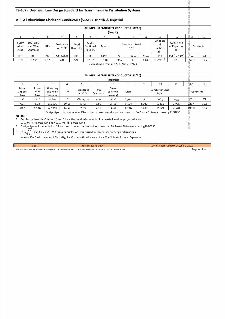
A-8: All Aluminium Clad Steel Conductors (SC/AC) - Metric & Imperial
ALUMINIUM CLAD STEEL CONDUCTOR (SC/AC)
(Metric)
1 2 3 4 5 6 7 8 9 10 11 12 13 14
Equiv
Alum
Area
Stranding
and Wire
Diameter
UTSResistance
at 20°C
Total
Diameter
Cross
Sectional
Area (A)
MassConductor Load
N/m
Modulus
of
Elasticity
(E)
Coefficient
of Expansion
(a)
Constants
mm2
mm kN Ohms/km mm mm2
kg/m W W100 W500 kPa per °C x 10-6
C1 C25.91 3/2.75 22.7 4.8 5.93 17.82 0.118 1.157 1.3 3.183 162 x 10
6 12.9 346.8 37.2
Values taken from AS1222, Part 2 - 1973
ALUMINIUM CLAD STEEL CONDUCTOR (SC/AC)
(Imperial)
1 2 3 4 5 6 7 8 9 10 11 12 13
Equiv
Copper
Area
Equiv
Alum
Area
Stranding
and Wire
Diameter
UTSResistance
at 20°C
Total
Diameter
Cross
Sectional
Area (A)
MassConductor Load
N/mConstants
in2 mm2 inches kN Ohms/km mm mm2 kg/m W W100 W500 C1 C2
.005 5.24 3/.1019 20.16 5.42 5.59 15.69 0.104 1.022 1.161 2.975 325.4 32.8
.012 12.16 7/.1019 44.57 2.33 7.77 36.44 0.246 2.407 2.529 4.570 496.0 76.2
Design figures in column 4 to 13 are direct conversions for values shown on SA Power Networks drawing P-30736Notes:
1. Conductor Loads in Column 10 and 11 are the result of conductor load + wind load on projected area.
W100 for 100 pascal wind and W500 for 500 pascal wind
2. Design figures in column 4 to 13 are direct conversions for values shown on SA Power Networks drawing P-30750
3. C1 = and C2 = ; are conductor constants used in temperature change calculations.
Where, E = Final modulus of Elasticity, A = Cross sectional area and a = Coefficient of Linear Expansion
8/12/2019 Aus Trans Std
http://slidepdf.com/reader/full/aus-trans-std 23/33
TS-107 - Overhead Line Design Standard for Transmission & Distribution Systems
TS-107 Authorised: Jehad Ali Date of Publication: 07 December 2012
The use of this Technical Standard is subject to the conditions stated in SA Power Networks disclaimer in front of this document. Page 23 of 38
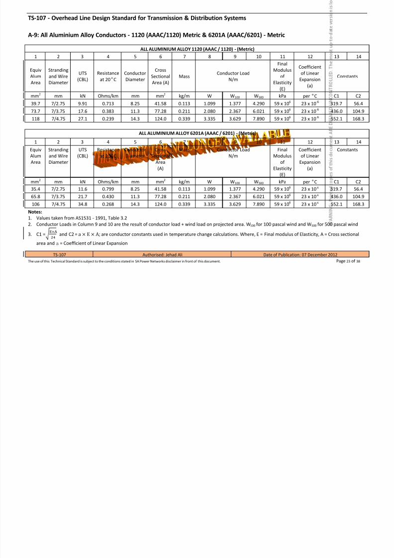
A-9: All Aluminium Alloy Conductors - 1120 (AAAC/1120) Metric & 6201A (AAAC/6201) - Metric
ALL ALUMINIUM ALLOY 1120 (AAAC / 1120) - (Metric)
1 2 3 4 5 6 7 8 9 10 11 12 13 14
Equiv
Alum
Area
Stranding
and Wire
Diameter
UTS
(CBL)
Resistance
at 20°C
Conductor
Diameter
Cross
Sectional
Area (A)
MassConductor Load
N/m
Final
Modulus
of
Elasticity
(E)
Coefficient
of Linear
Expansion
(a)
Constants
mm2
mm kN Ohms/km mm mm2
kg/m W W100 W500 kPa per °C C1 C239.7 7/2.75 9.91 0.713 8.25 41.58 0.113 1.099 1.377 4.290 59 x 10
6 23 x 10
-6 319.7 56.4
73.7 7/3.75 17.6 0.383 11.3 77.28 0.211 2.080 2.367 6.021 59 x 106 23 x 10
-6 436.0 104.9
118 7/4.75 27.1 0.239 14.3 124.0 0.339 3.335 3.629 7.890 59 x 106 23 x 10-6 552.1 168.3
ALL ALUMINIUM ALLOY 6201A (AAAC / 6201) - (Metric)
1 2 3 4 5 6 7 8 9 10 11 12 13 14
Equiv
Alum
Area
Stranding
and Wire
Diameter
UTS
(CBL)
Resistance
at 20°C
Conductor
Diameter
Cross
Sectional
Area
(A)
Mass Conductor Load
N/m
Final
Modulus
of
Elasticity
(E)
Coefficient
of Linear
Expansion
(a)
Constants
mm2 mm kN Ohms/km mm mm2 kg/m W W100 W500 kPa per °C C1 C2
35.4 7/2.75 11.6 0.799 8.25 41.58 0.113 1.099 1.377 4.290 59 x 106 23 x 10-6 319.7 56.4
65.8 7/3.75 21.7 0.430 11.3 77.28 0.211 2.080 2.367 6.021 59 x 106 23 x 10-6 436.0 104.9
106 7/4.75 34.8 0.268 14.3 124.0 0.339 3.335 3.629 7.890 59 x 106 23 x 10-6 552.1 168.3
Notes:
1. Values taken from AS1531 - 1991, Table 3.2
2. Conductor Loads in Column 9 and 10 are the result of conductor load + wind load on projected area. W100 for 100 pascal wind and W500 for 500 pascal wind
3. C1 = and C2 = ; are conductor constants used in temperature change calculations. Where, E = Final modulus of Elasticity, A = Cross sectional
area and a = Coefficient of Linear Expansion
8/12/2019 Aus Trans Std
http://slidepdf.com/reader/full/aus-trans-std 24/33
TS-107 - Overhead Line Design Standard for Transmission & Distribution Systems
TS-107 Authorised: Jehad Ali Date of Publication: 07 December 2012
The use of this Technical Standard is subject to the conditions stated in SA Power Networks disclaimer in front of this document. Page 24 of 38
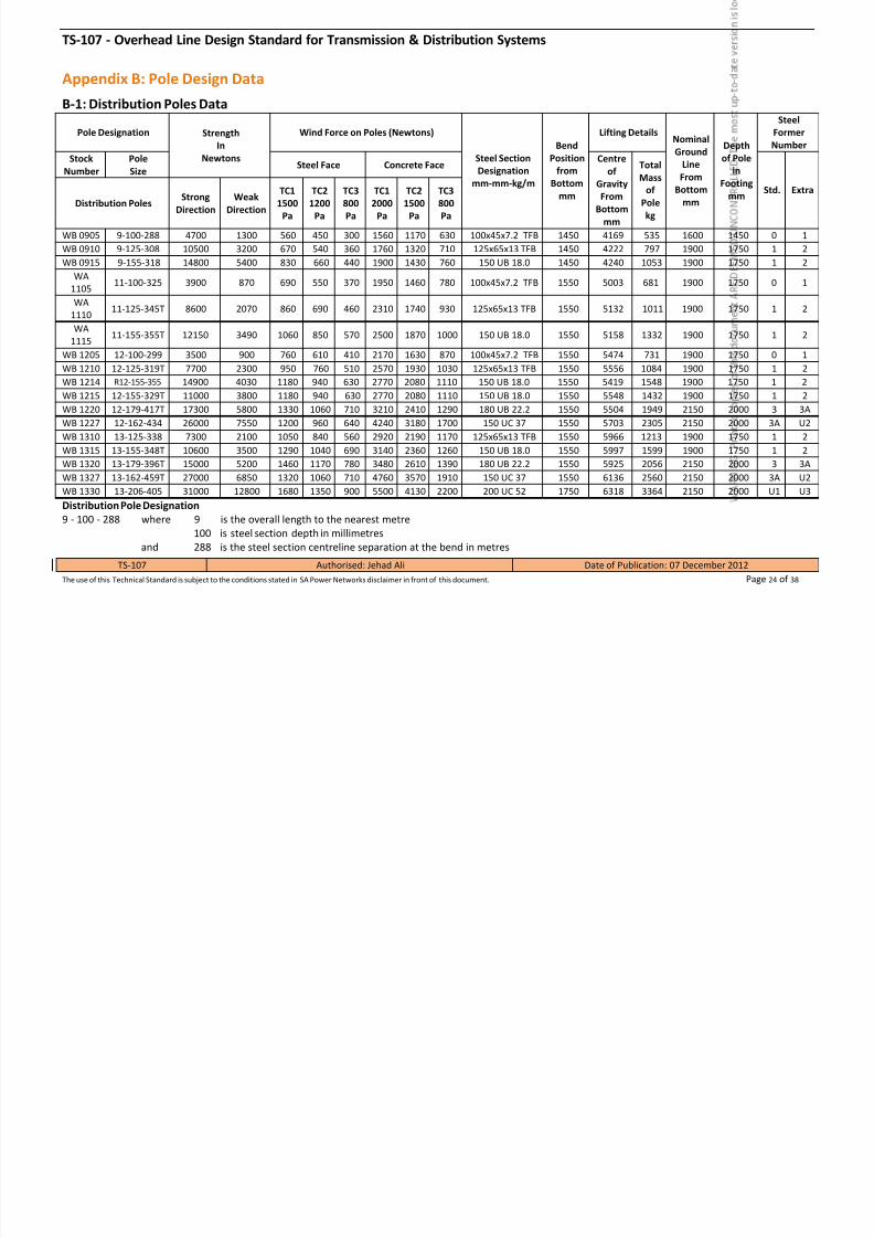
Appendix B: Pole Design Data
B-1: Distribution Poles Data
Pole Designation Strength
In
Newtons
Wind Force on Poles (Newtons)
Steel Section
Designation
mm-mm-kg/m
Bend
Position
from
Bottom
mm
Lifting DetailsNominal
Ground
Line
From
Bottom
mm
Depth
of Pole
in
Footing
mm
Steel
Former
Number
Stock
Number
Pole
SizeSteel Face Concrete Face
Centre
of
Gravity
From
Bottom
mm
Total
Mass
of
Pole
kg
Std. Extra
Distribution PolesStrong
Direction
Weak
Direction
TC1
1500
Pa
TC2
1200
Pa
TC3
800
Pa
TC1
2000
Pa
TC2
1500
Pa
TC3
800
Pa
WB 0905 9-100-288 4700 1300 560 450 300 1560 1170 630 100x45x7.2 TFB 1450 4169 535 1600 1450 0 1
WB 0910 9-125-308 10500 3200 670 540 360 1760 1320 710 125x65x13 TFB 1450 4222 797 1900 1750 1 2
WB 0915 9-155-318 14800 5400 830 660 440 1900 1430 760 150 UB 18.0 1450 4240 1053 1900 1750 1 2
WA
110511-100-325 3900 870 690 550 370 1950 1460 780 100x45x7.2 TFB 1550 5003 681 1900 1750 0 1
WA
111011-125-345T 8600 2070 860 690 460 2310 1740 930 125x65x13 TFB 1550 5132 1011 1900 1750 1 2
WA
111511-155-355T 12150 3490 1060 850 570 2500 1870 1000 150 UB 18.0 1550 5158 1332 1900 1750 1 2
WB 1205 12-100-299 3500 900 760 610 410 2170 1630 870 100x45x7.2 TFB 1550 5474 731 1900 1750 0 1
WB 1210 12-125-319T 7700 2300 950 760 510 2570 1930 1030 125x65x13 TFB 1550 5556 1084 1900 1750 1 2
WB 1214 R12-155-355 14900 4030 1180 940 630 2770 2080 1110 150 UB 18.0 1550 5419 1548 1900 1750 1 2
WB 1215 12-155-329T 11000 3800 1180 940 630 2770 2080 1110 150 UB 18.0 1550 5548 1432 1900 1750 1 2
WB 1220 12-179-417T 17300 5800 1330 1060 710 3210 2410 1290 180 UB 22.2 1550 5504 1949 2150 2000 3 3A
WB 1227 12-162-434 26000 7550 1200 960 640 4240 3180 1700 150 UC 37 1550 5703 2305 2150 2000 3A U2
WB 1310 13-125-338 7300 2100 1050 840 560 2920 2190 1170 125x65x13 TFB 1550 5966 1213 1900 1750 1 2
WB 1315 13-155-348T 10600 3500 1290 1040 690 3140 2360 1260 150 UB 18.0 1550 5997 1599 1900 1750 1 2
WB 1320 13-179-396T 15000 5200 1460 1170 780 3480 2610 1390 180 UB 22.2 1550 5925 2056 2150 2000 3 3A
WB 1327 13-162-459T 27000 6850 1320 1060 710 4760 3570 1910 150 UC 37 1550 6136 2560 2150 2000 3A U2
WB 1330 13-206-405 31000 12800 1680 1350 900 5500 4130 2200 200 UC 52 1750 6318 3364 2150 2000 U1 U3
Distribution Pole Designation
9 - 100 - 288 where 9 is the overall length to the nearest metre
100 is steel section depth in millimetres
and 288 is the steel section centreline separation at the bend in metres
8/12/2019 Aus Trans Std
http://slidepdf.com/reader/full/aus-trans-std 25/33
TS-107 - Overhead Line Design Standard for Transmission & Distribution Systems
TS-107 Authorised: Jehad Ali Date of Publication: 07 December 2012
The use of this Technical Standard is subject to the conditions stated in SA Power Networks disclaimer in front of this document. Page 25 of 38
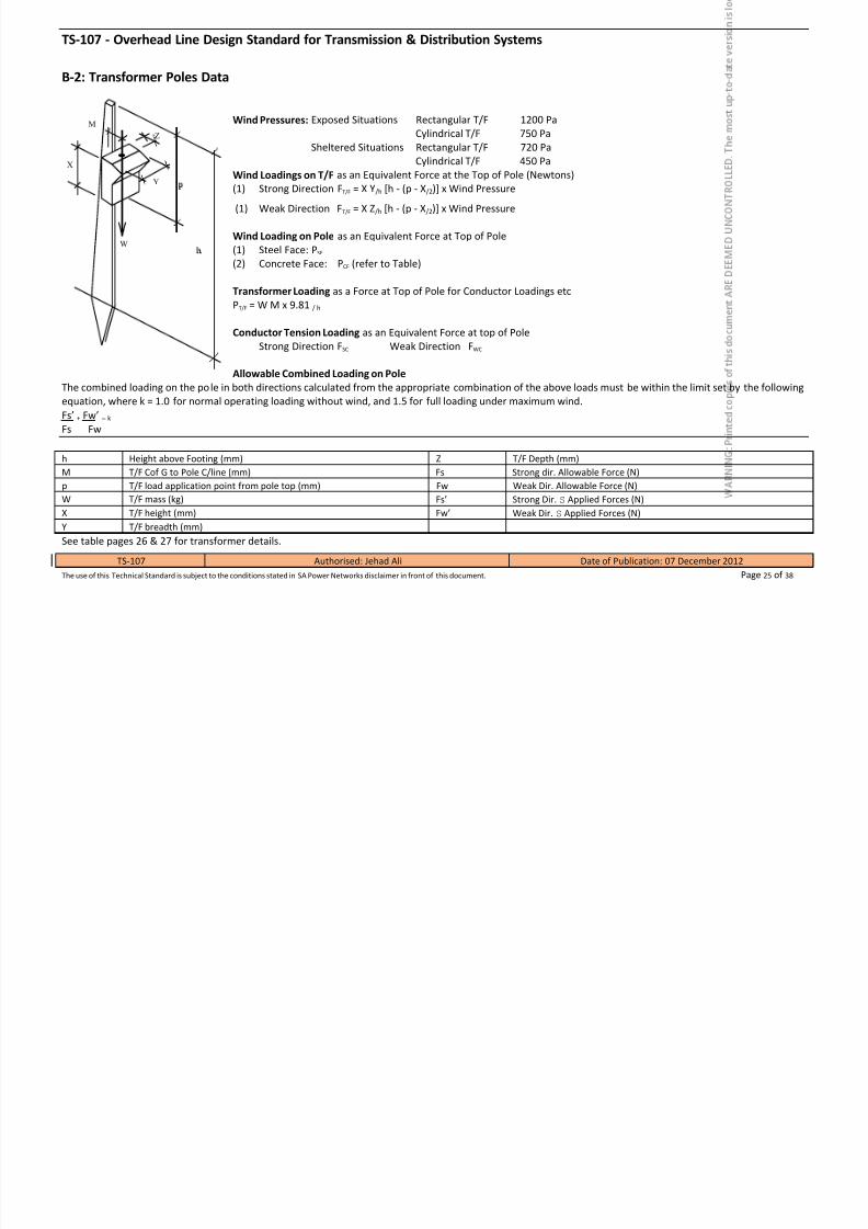
B-2: Transformer Poles Data
Wind Pressures: Exposed Situations Rectangular T/F 1200 Pa
Cylindrical T/F 750 Pa
Sheltered Situations Rectangular T/F 720 Pa
Cylindrical T/F 450 Pa
Wind Loadings on T/F as an Equivalent Force at the Top of Pole (Newtons)
(1) Strong Direction FT/F = X Y/h [h - (p - X/2)] x Wind Pressure
(1) Weak Direction FT/F = X Z/h [h - (p - X/2)] x Wind Pressure
Wind Loading on Pole as an Equivalent Force at Top of Pole
(1) Steel Face: PSF
(2) Concrete Face: PCF (refer to Table)
Transformer Loading as a Force at Top of Pole for Conductor Loadings etc
PT/F = W M x 9.81 / h
Conductor Tension Loading as an Equivalent Force at top of Pole
Strong Direction FSC Weak Direction FWC
Allowable Combined Loading on Pole
The combined loading on the pole in both directions calculated from the appropriate combination of the above loads must be within the limit set by the following
equation, where k = 1.0 for normal operating loading without wind, and 1.5 for full loading under maximum wind.
Fs’ + Fw’ = k
Fs Fw
h Height above Footing (mm) Z T/F Depth (mm)
M T/F Cof G to Pole C/line (mm) Fs Strong dir. Allowable Force (N)
p T/F load application point from pole top (mm) Fw Weak Dir. Allowable Force (N)
W T/F mass (kg) Fs’ Strong Dir. S Applied Forces (N)
X T/F height (mm) Fw’ Weak Dir. S Applied Forces (N)
Y T/F breadth (mm)
See table pages 26 & 27 for transformer details.
W
X
M
Z
Y
8/12/2019 Aus Trans Std
http://slidepdf.com/reader/full/aus-trans-std 26/33
TS-107 - Overhead Line Design Standard for Transmission & Distribution Systems
TS-107 Authorised: Jehad Ali Date of Publication: 07 December 2012
The use of this Technical Standard is subject to the conditions stated in SA Power Networks disclaimer in front of this document. Page 26 of 38
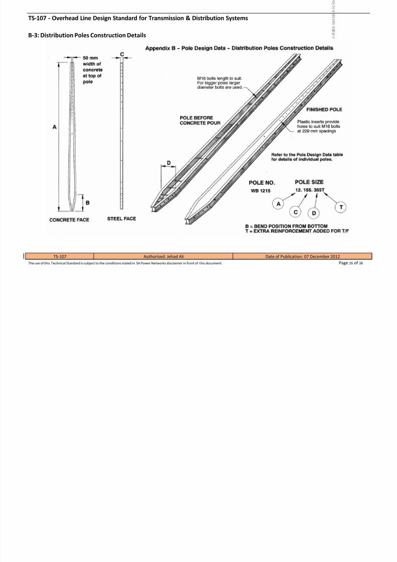
B-3: Distribution Poles Construction Details

8/12/2019 Aus Trans Std
http://slidepdf.com/reader/full/aus-trans-std 27/33
TS-107 - Overhead Line Design Standard for Transmission & Distribution Systems
TS-107 Authorised: Jehad Ali Date of Publication: 07 December 2012
The use of this Technical Standard is subject to the conditions stated in SA Power Networks disclaimer in front of this document. Page 27 of 38
B-4: Transformer DetailsThe figures below (which have been provided by Tyree) apply to Tyree Transformers supplied after 1995.
Voltage DescriptionCapacity
kVASupply Item Number Current Contract
Mass
kgShape
Height *
mm
Width *
mm
Depth *
mm
11 kVSingle Phase
(11/7.6kV)
10 150 Cylindrical 900 520 510
16 LA5116 155 Cylindrical 840 570 580
20 185 Cylindrical 900 520 510
50 LA5119 335 Cylindrical 1090 725 710
50 LA5182 335 Cylindrical 1040 725 710
11 kV
Three Phase
(11/7.6kV)
(Wilson T/F)
25 LA5316 265 Rectangular 1075 960 580
30 345 Cylindrical 1250 720 61050 410 Cylindrical 1420 620 640
63 LA5327 485 Rectangular 1175 960 630
100 LA5336 740 Rectangular 1240 1180 950
150 1100 Rectangular 1400 1230 750
200 LA5346 1220 Rectangular 1410 1210 905
200 1011348 1175 Rectangular TBA TBA TBA
315 LA5356 1450 Rectangular 1290 1290 945
33 kV Single Phase
10 265 Cylindrical 950 800 1130
20 300 Cylindrical 950 845 1020
25 LA6116 260 Cylindrical 1050 630 960
50 LA6117 400 Cylindrical 1070 700 1030
33 kV Three Phase
25 LA6499 600 Rectangular 1030 1210 1200
30 710 Cylindrical 960 1110 1190
50 830 Cylindrical 1060 1110 1150
63 LA6503 830 Rectangular 1030 1210 1200
100 LA6504 1255 Rectangular 1225 1145 1250
150 1555 Rectangular 1425 1105 1340
200 LA6508 1725 Rectangular 1425 1185 1320
19 kV SWERSingle Phase
SWER Dist
10 LA0110 135 Cylindrical 840 570 950
25 1012328 200 Cylindrical 840 570 1000
11 / 19 kV Single Phase SWER Isol 150 LA5196 1090 Rectangular 1500 970 1230
8/12/2019 Aus Trans Std
http://slidepdf.com/reader/full/aus-trans-std 28/33
TS-107 - Overhead Line Design Standard for Transmission & Distribution Systems
TS-107 Authorised: Jehad Ali Date of Publication: 07 December 2012
The use of this Technical Standard is subject to the conditions stated in SA Power Networks disclaimer in front of this document. Page 28 of 38
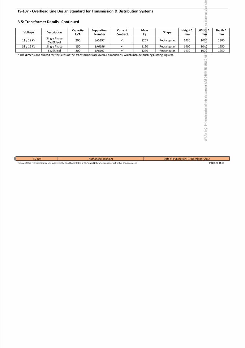
B-5: Transformer Details - Continued
Voltage DescriptionCapacity
kVA
Supply Item
Number
Current
Contract
Mass
kgShape
Height *
mm
Width *
mm
Depth *
mm
11 / 19 kVSingle Phase
SWER Isol200 LA5197 1265 Rectangular 1430 1070 1300
33 / 19 kV Single Phase 150 LA6196 1120 Rectangular 1400 1040 1250
SWER Isol 200 LA6197 1270 Rectangular 1430 1070 1250
* The dimensions quoted for the sizes of the transformers are overall dimensions, which include bushings, lifting lugs etc.
8/12/2019 Aus Trans Std
http://slidepdf.com/reader/full/aus-trans-std 29/33
TS-107 - Overhead Line Design Standard for Transmission & Distribution Systems
TS-107 Authorised: Jehad Ali Date of Publication: 07 December 2012
The use of this Technical Standard is subject to the conditions stated in SA Power Networks disclaimer in front of this document. Page 29 of 38
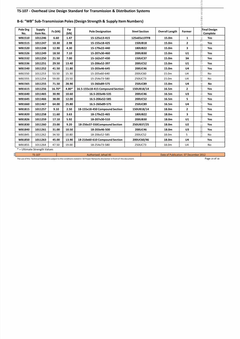
B-6: “WB” Sub-Transmission Poles (Design Strength & Supply Item Numbers)
Pole Drg
No.
Supply
Item No.Fs (kN)
Fw
(kN)Pole Designation Steel Section Overall Length Former
Final Design
Complete
WB1510 1011246 6.60 1.47 15-125x13-415 125x65x13TFB 15.0m 1 Yes
WB1515 1011247 10.30 2.98 15-155x18-425 150UB18 15.0m 2 Yes
WB1520 1011248 12.90 4.30 15-179x22-440 180UB22 15.0m 3 Yes
WB1526 1011249 18.50 7.10 15-207x30-460 200UB30 15.0m U1 Yes
WB1532 1011250 21.50 7.00 15-162x37-430 150UC37 15.0m 3A YesWB1536 1011251 29.50 13.40 15-206x52-397 200UC52 15.0m U1 Yes
WB1540 1011252 41.50 11.80 15-203x46-645 200UC46 15.0m U4 Yes
WB1550 1011253 53.50 15.30 15-205x60-640 200UC60 15.0m U4 No
WB1555 1011254 59.00 23.50 15-254x73-580 250UC73 15.0m U4 No
WB1565 1011255 71.50 28.90 15-260x89-575 250UC89 15.0m U4 No
WB1615 1011256 16.70* 4.80* 16.5-155x18-415 Compound Section 150UB18/14 16.5m 2 Yes
WB1640 1011465 30.90 10.60 16.5-203x46-535 200UC46 16.5m U3 Yes
WB1645 1011466 38.00 12.00 16.5-206x52-585 200UC52 16.5m 5 Yes
WB1660 1011467 64.00 25.80 16.5-260x89-575 250UC89 16.5m U4 Yes
WB1815 1011257 9.10 2.50 18-155x18-450 Compound Section 150UB18/14 18.0m 2 Yes
WB1820 1011258 11.60 3.63 18-179x22-465 180UB22 18.0m 3 Yes
WB1826 1011259 17.10 5.92 18-207x30-510 200UB30 18.0m U1 Yes
WB1830 1011260 23.00 9.20 18-256x37-550Compound Section 250UB37/25 18.0m U2 Yes
WB1840 1011261 31.00 10.50 18-203x46-500 200UC46 18.0m U3 Yes
WB1845 1011262 34.50 10.80 18-206x52-585 200UC52 18.0m 5 No
WB1850 1011263 45.00 13.90 18-210x60-610 Compound Section 200UC60/46 18.0m U4 Yes
WB1855 1011264 47.50 19.00 18-254x73-580 250UC73 18.0m U4 No
* = Ultimate Strength Values
8/12/2019 Aus Trans Std
http://slidepdf.com/reader/full/aus-trans-std 30/33
TS-107 - Overhead Line Design Standard for Transmission & Distribution Systems
TS-107 Authorised: Jehad Ali Date of Publication: 07 December 2012
The use of this Technical Standard is subject to the conditions stated in SA Power Networks disclaimer in front of this document. Page 30 of 38
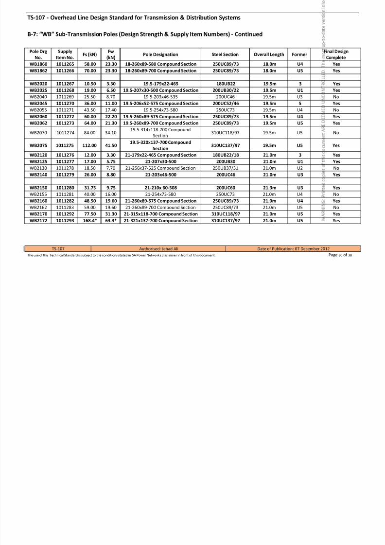
B-7: “WB” Sub-Transmission Poles (Design Strength & Supply Item Numbers) - Continued
Pole Drg
No.
Supply
Item No.Fs (kN)
Fw
(kN)Pole Designation Steel Section Overall Length Former
Final Design
Complete
WB1860 1011265 58.00 23.30 18-260x89-580 Compound Section 250UC89/73 18.0m U4 Yes
WB1862 1011266 70.00 23.30 18-260x89-700 Compound Section 250UC89/73 18.0m U5 Yes
WB2020 1011267 10.50 3.30 19.5-179x22-465 180UB22 19.5m 3 Yes
WB2025 1011268 19.00 6.50 19.5-207x30-500 Compound Section 200UB30/22 19.5m U1 Yes
WB2040 1011269 25.50 8.70 19.5-203x46-535 200UC46 19.5m U3 No
WB2045 1011270 36.00 11.00 19.5-206x52-575 Compound Section 200UC52/46 19.5m 5 Yes
WB2055 1011271 43.50 17.40 19.5-254x73-580 250UC73 19.5m U4 No
WB2060 1011272 60.00 22.20 19.5-260x89-575 Compound Section 250UC89/73 19.5m U4 Yes
WB2062 1011273 64.00 21.30 19.5-260x89-700 Compound Section 250UC89/73 19.5m U5 Yes
WB2070 1011274 84.00 34.1019.5-314x118-700 Compound
Section310UC118/97 19.5m U5 No
WB2075 1011275 112.00 41.5019.5-320x137-700 Compound
Section310UC137/97 19.5m U5 Yes
WB2120 1011276 12.00 3.30 21-179x22-465 Compound Section 180UB22/18 21.0m 3 Yes
WB2125 1011277 17.00 5.75 21-207x30-500 200UB30 21.0m U1 Yes
WB2130 1011278 18.50 7.70 21-256x37-525 Compound Section 250UB37/31 21.0m U2 No
WB2140 1011279 26.00 8.80 21-203x46-500 200UC46 21.0m U3 Yes
WB2150 1011280 31.75 9.75 21-210x 60-508 200UC60 21.3m U3 Yes
WB2155 1011281 40.00 16.00 21-254x73-580 250UC73 21.0m U4 No
WB2160 1011282 48.50 19.60 21-260x89-575 Compound Section 250UC89/73 21.0m U4 Yes
WB2162 1011283 59.00 19.60 21-260x89-700 Compound Section 250UC89/73 21.0m U5 No
WB2170 1011292 77.50 31.30 21-315x118-700 Compound Section 310UC118/97 21.0m U5 Yes
WB2172 1011293 168.4* 63.3* 21-321x137-700 Compound Section 310UC137/97 21.0m U5 Yes
8/12/2019 Aus Trans Std
http://slidepdf.com/reader/full/aus-trans-std 31/33
TS-107 - Overhead Line Design Standard for Transmission & Distribution Systems
TS-107 Authorised: Jehad Ali Date of Publication: 07 December 2012
The use of this Technical Standard is subject to the conditions stated in SA Power Networks disclaimer in front of this document. Page 31 of 38
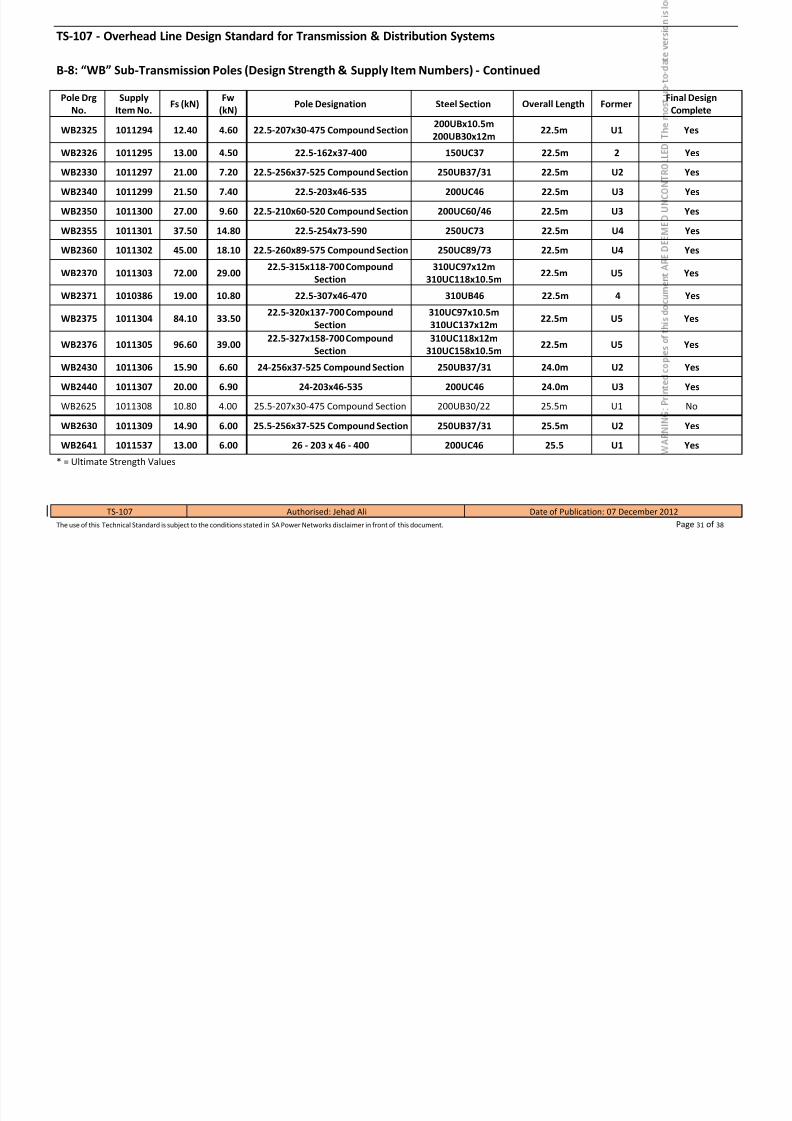
B-8: “WB” Sub-Transmission Poles (Design Strength & Supply Item Numbers) - Continued
Pole Drg
No.
Supply
Item No.Fs (kN)
Fw
(kN)Pole Designation Steel Section Overall Length Former
Final Design
Complete
WB2325 1011294 12.40 4.60 22.5-207x30-475 Compound Section200UBx10.5m
200UB30x12m22.5m U1 Yes
WB2326 1011295 13.00 4.50 22.5-162x37-400 150UC37 22.5m 2 Yes
WB2330 1011297 21.00 7.20 22.5-256x37-525 Compound Section 250UB37/31 22.5m U2 Yes
WB2340 1011299 21.50 7.40 22.5-203x46-535 200UC46 22.5m U3 YesWB2350 1011300 27.00 9.60 22.5-210x60-520 Compound Section 200UC60/46 22.5m U3 Yes
WB2355 1011301 37.50 14.80 22.5-254x73-590 250UC73 22.5m U4 Yes
WB2360 1011302 45.00 18.10 22.5-260x89-575 Compound Section 250UC89/73 22.5m U4 Yes
WB2370 1011303 72.00 29.0022.5-315x118-700 Compound
Section
310UC97x12m
310UC118x10.5m22.5m U5 Yes
WB2371 1010386 19.00 10.80 22.5-307x46-470 310UB46 22.5m 4 Yes
WB2375 1011304 84.10 33.5022.5-320x137-700 Compound
Section
310UC97x10.5m
310UC137x12m22.5m U5 Yes
WB2376 1011305 96.60 39.0022.5-327x158-700 Compound
Section
310UC118x12m
310UC158x10.5m22.5m U5 Yes
WB2430 1011306 15.90 6.60 24-256x37-525 Compound Section 250UB37/31 24.0m U2 Yes
WB2440 1011307 20.00 6.90 24-203x46-535 200UC46 24.0m U3 YesWB2625 1011308 10.80 4.00 25.5-207x30-475 Compound Section 200UB30/22 25.5m U1 No
WB2630 1011309 14.90 6.00 25.5-256x37-525 Compound Section 250UB37/31 25.5m U2 Yes
WB2641 1011537 13.00 6.00 26 - 203 x 46 - 400 200UC46 25.5 U1 Yes
* = Ultimate Strength Values
8/12/2019 Aus Trans Std
http://slidepdf.com/reader/full/aus-trans-std 32/33
TS-107 - Overhead Line Design Standard for Transmission & Distribution Systems
TS-107 Authorised: Jehad Ali Date of Publication: 07 December 2012
The use of this Technical Standard is subject to the conditions stated in SA Power Networks disclaimer in front of this document. Page 37 of 38
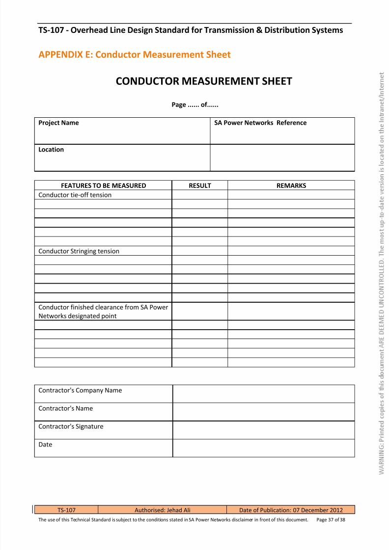
APPENDIX E: Conductor Measurement Sheet
CONDUCTOR MEASUREMENT SHEET
Page ...... of......
Project Name SA Power Networks Reference
Location
FEATURES TO BE MEASURED RESULT REMARKS
Conductor tie-off tension
Conductor Stringing tension
Conductor finished clearance from SA Power
Networks designated point
Contractor's Company Name
Contractor's Name
Contractor's Signature
Date
8/12/2019 Aus Trans Std
http://slidepdf.com/reader/full/aus-trans-std 33/33
TS-107 - Overhead Line Design Standard for Transmission & Distribution Systems
Refer to a Separate Document for following TS-107- Appendix F & G
APPENDIX F: Atmospheric Corrosion Maps of South Australia
APPENDIX G: DPTI’s Maps of High Load Corridor
Please Note: Appendix F and Appendix G are not included in this document
but can be found in a separate file on the SA Power Networks
intranet.