Axialkolben-Verstellpumpen Baureihe J-VZ Variable ... · Axialkolben-Verstellpumpen Baureihe J-VZ...
25
Variable displacement axial piston pumps Series J-VZ Pompe variabili a pistoni assiali Serie J-VZ Axialkolben-Verstellpumpen Baureihe J-VZ
-
Upload
truongphuc -
Category
Documents
-
view
224 -
download
0
Transcript of Axialkolben-Verstellpumpen Baureihe J-VZ Variable ... · Axialkolben-Verstellpumpen Baureihe J-VZ...
Variable displacement axial piston pumps Series J-VZ
Pompe variabili a pistoni assiali Serie J-VZ
Axialkolben-Verstellpumpen Baureihe J-VZ
Axialkolben-Verstellpumpen Baureihe J-VZVariable displacement axial piston pumps Series J-VZPompe variabili a pistoni assiali Serie J-VZ
Inhaltsverzeichnis . Contents . Indice Seite . Page . Pagina
Allgemeine Beschreibung ......................................................................................................................................................... 3General descriptionDescrizione generale
Regel- und Verstellorgane ........................................................................................................................................................ 4Control devicesDispositivi di regolazione
Kenngrößen .............................................................................................................................................................................. 5Operating dataDati caratteristici
Drehrichtung und Masse ........................................................................................................................................................... 6Sense of rotation and weightSenso di rotazione e peso
Nullhubdruckeinstellbereich mechanisch .................................................................................................................................. 6Adjustable pressure rangeCampo di registrazione meccanica della pressione di azzeramento
Typenschlüssel bei Verwendung vonModel codeChiave di ordinazione con l´utilizzo del
-Regler A, Control A, Regolatore A ................................................................................................................................. 7-Regler A-RC, Control A-RC, Regolatore A-RC .............................................................................................................. 7-Regler SA, Control SA, Regolatore SA .......................................................................................................................... 8-Regler CH, Control CH, Regolatore CH ........................................................................................................................ 8-Regler CJ, Control CJ, Regolatore CJ ........................................................................................................................... 9
KennlinienCharacteristicsCurve caratteristiche
-Dynamisches Verhalten des Nullhubdruckreglers A .....................................................................................................10Dynamic performance of pressure compensator control APrestazione dinamica del compensatore A
-Geräuschmessungen (Lp-p2) ........................................................................................................................................ 11Noise level (Lp-p2)Livelli di rumorosità (Lp-p2)
-Wirkungsgrad, Förderstrom, Leistung (η, qv2, e, P2-p2) ................................................................................................. 12Performance characteristics (η, qv2, e, P2-p2)Rendimento, portata, potenza (η, qv2, e, P2-p2)
-Externer Leckstrom (qvd-p2) .......................................................................................................................................... 13External leakage flow (qvd-p2)Drenaggio esterno (qvd-p2)
-Nullhubleistung (PqvNull-p2) ........................................................................................................................................... 14Dead head horsepower (Pqvzero-p2)Potenza dispersa in compensazione (Pqvzero-p2)
Geräteabmessungen ....................................................................................................................................................... 15 - 24Installation dimensionsDimensioni
2
Axialkolben-Verstellpumpen Baureihe J-VZVariable displacement axial piston pumps Series J-VZPompe variabili a pistoni assiali Serie J-VZ
Allgemeine Beschreibung . General description . Descrizione generale
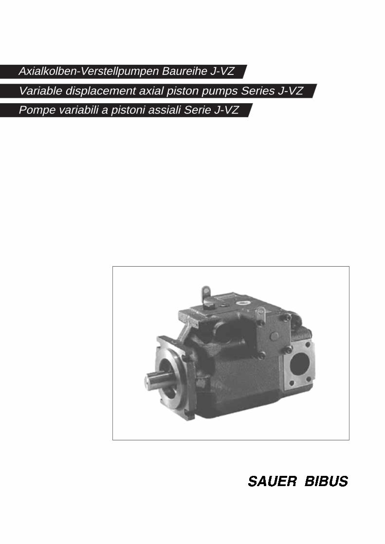
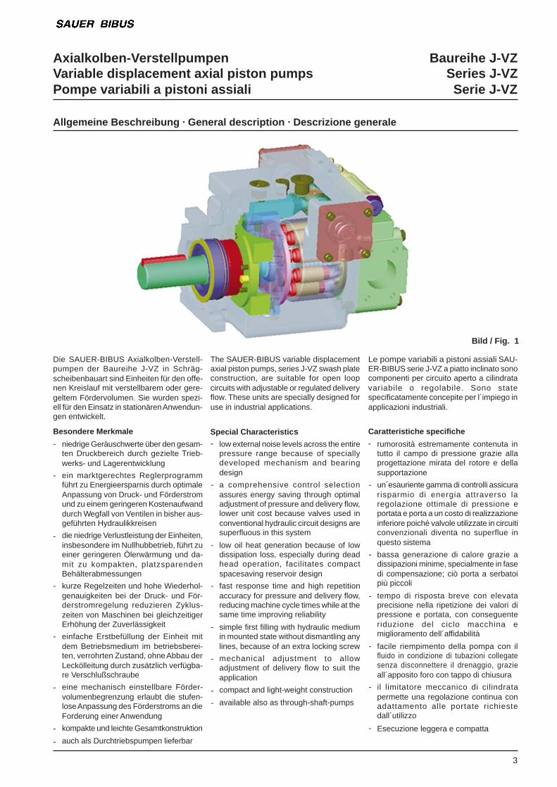
Die SAUER-BIBUS Axialkolben-Verstell-pumpen der Baureihe J-VZ in Schräg-scheibenbauart sind Einheiten für den offe-nen Kreislauf mit verstellbarem oder gere-geltem Fördervolumen. Sie wurden spezi-ell für den Einsatz in stationären Anwendun-gen entwickelt.
Besondere Merkmale
niedrige Geräuschwerte über den gesam-ten Druckbereich durch gezielte Trieb-werks- und Lagerentwicklung
ein marktgerechtes Reglerprogrammführt zu Energieersparnis durch optimaleAnpassung von Druck- und Förderstromund zu einem geringeren Kostenaufwanddurch Wegfall von Ventilen in bisher aus-geführten Hydraulikkreisen
die niedrige Verlustleistung der Einheiten,insbesondere im Nullhubbetrieb, führt zueiner geringeren Ölerwärmung und da-mit zu kompakten, platzsparendenBehälterabmessungen
kurze Regelzeiten und hohe Wiederhol-genauigkeiten bei der Druck- und För-derstromregelung reduzieren Zyklus-zeiten von Maschinen bei gleichzeitigerErhöhung der Zuverlässigkeit
einfache Erstbefüllung der Einheit mitdem Betriebsmedium im betriebsberei-ten, verrohrten Zustand, ohne Abbau derLeckölleitung durch zusätzlich verfügba-re Verschlußschraube
eine mechanisch einstellbare Förder-volumenbegrenzung erlaubt die stufen-lose Anpassung des Förderstroms an dieForderung einer Anwendung
kompakte und leichte Gesamtkonstruktion
auch als Durchtriebspumpen lieferbar
The SAUER-BIBUS variable displacementaxial piston pumps, series J-VZ swash plateconstruction, are suitable for open loopcircuits with adjustable or regulated deliveryflow. These units are specially designed foruse in industrial applications.
Special Characteristic slow external noise levels across the entirepressure range because of speciallydeveloped mechanism and bearingdesign
a comprehensive control selectionassures energy saving through optimaladjustment of pressure and delivery flow,lower unit cost because valves used inconventional hydraulic circuit designs aresuperfluous in this system
low oil heat generation because of lowdissipation loss, especially during deadhead operation, facilitates compactspacesaving reservoir design
fast response time and high repetitionaccuracy for pressure and delivery flow,reducing machine cycle times while at thesame time improving reliability
simple first filling with hydraulic mediumin mounted state without dismantling anylines, because of an extra locking screw
mechanical adjustment to allowadjustment of delivery flow to suit theapplication
compact and light-weight construction
available also as through-shaft-pumps
Le pompe variabili a pistoni assiali SAU-ER-BIBUS serie J-VZ a piatto inclinato sonocomponenti per circuito aperto a cilindratavariabile o regolabile. Sono statespecificatamente concepite per l´impiego inapplicazioni industriali.
Caratteristiche specifiche
rumorosità estremamente contenuta intutto il campo di pressione grazie allaprogettazione mirata del rotore e dellasupportazione
un´esauriente gamma di controlli assicurarisparmio di energia attraverso laregolazione ottimale di pressione eportata e porta a un costo di realizzazioneinferiore poichè valvole utilizzate in circuiticonvenzionali diventa no superflue inquesto sistema
bassa generazione di calore grazie adissipazioni minime, specialmente in fasedi compensazione; ciò porta a serbatoipiù piccoli
tempo di risposta breve con elevataprecisione nella ripetizione dei valori dipressione e portata, con conseguenteriduzione del ciclo macchina emiglioramento dell´affidabilità
facile riempimento della pompa con ilfluido in condizione di tubazioni collegatesenza disconnettere il drenaggio, grazieall´apposito foro con tappo di chiusura
il limitatore meccanico di cilindratapermette una regolazione continua conadattamento alle portate richiestedall´utilizzo
Esecuzione leggera e compatta
-
-
-
-
-
-
-
-
-
-
-
-
-
-
-
-
-
-
-
-
-
3
Bild / Fig. 1
-
-
Axialkolben-Verstellpumpen Baureihe J-VZVariable displacement axial piston pumps Series J-VZPompe variabili a pistoni assiali Serie J-VZ
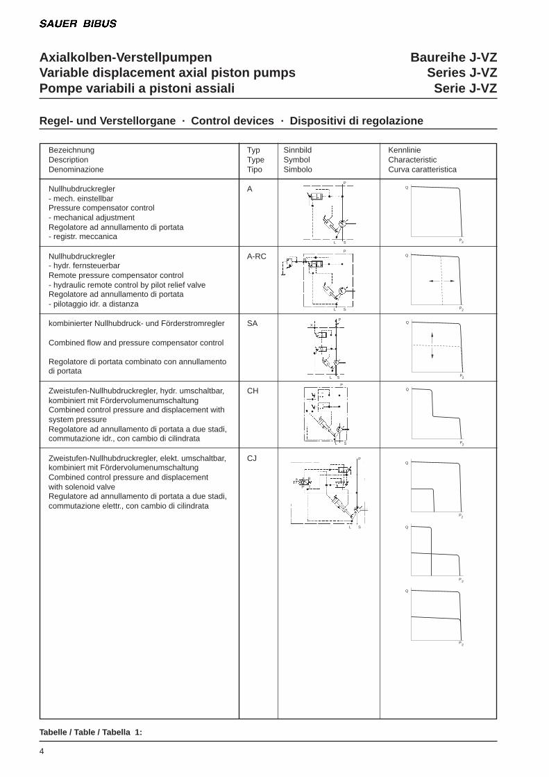
Tabelle / Table / Tabella 1:
Regel- und Verstellorgane . Control devices . Dispositivi di regolazione
4
P
SL
P
SL
X
SL
P
S
P
SL
A B
TP
a
P2
P2
P2
P2
P2
P2
P2
Q
Q
Q
Q
Q
Q
Q
Sinnbild KennlinieSymbol CharacteristicSimbolo Curva caratteristica
Bezeichnung TypDescription TypeDenominazione Tipo
Nullhubdruckregler A- mech. einstellbarPressure compensator control- mechanical adjustmentRegolatore ad annullamento di portata- registr. meccanica
Nullhubdruckregler A-RC- hydr. fernsteuerbarRemote pressure compensator control- hydraulic remote control by pilot relief valveRegolatore ad annullamento di portata- pilotaggio idr. a distanza
kombinierter Nullhubdruck- und Förderstromregler SA
Combined flow and pressure compensator control
Regolatore di portata combinato con annullamentodi portata
Zweistufen-Nullhubdruckregler, hydr. umschaltbar, CHkombiniert mit FördervolumenumschaltungCombined control pressure and displacement withsystem pressureRegolatore ad annullamento di portata a due stadi,commutazione idr., con cambio di cilindrata
Zweistufen-Nullhubdruckregler, elekt. umschaltbar, CJkombiniert mit FördervolumenumschaltungCombined control pressure and displacementwith solenoid valveRegulatore ad annullamento di portata a due stadi,commutazione elettr., con cambio di cilindrata
P
L
Axialkolben-Verstellpumpen Baureihe J-VZVariable displacement axial piston pumps Series J-VZPompe variabili a pistoni assiali Serie J-VZ
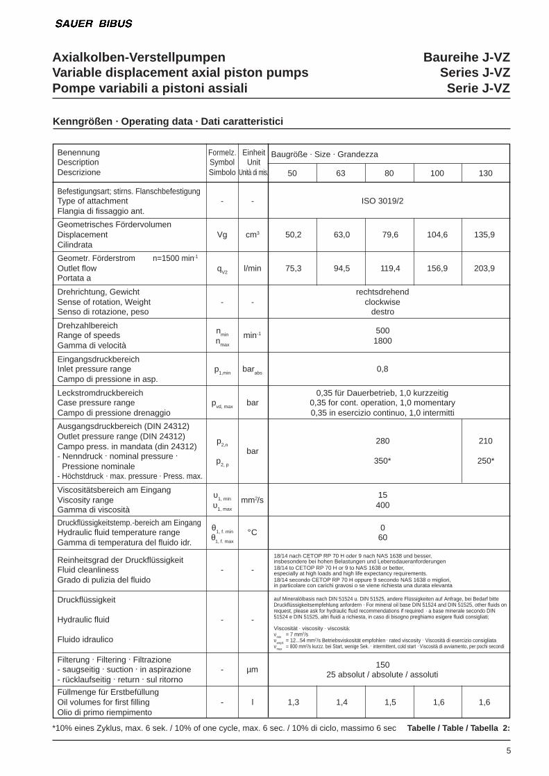
Kenngrößen . Operating data . Dati caratteristici
5
Benennung Formelz. EinheitDescription Symbol UnitDescrizione Simbolo Unità di mis.
Befestigungsart; stirns. FlanschbefestigungType of attachment - -Flangia di fissaggio ant.
Geometrisches FördervolumenDisplacement Vg cm3
Cilindrata
Geometr. Förderstrom n=1500 min-1
Outlet flow qV2 l/minPortata a
Drehrichtung, GewichtSense of rotation, Weight - -Senso di rotazione, peso
DrehzahlbereichnminRange of speedsnmax
min-1
Gamma di velocità
EingangsdruckbereichInlet pressure range p1,min barabs
Campo di pressione in asp.
LeckstromdruckbereichCase pressure range pvd, max barCampo di pressione drenaggio
Ausgangsdruckbereich (DIN 24312)Outlet pressure range (DIN 24312)Campo press. in mandata (din 24312)
p2,n
- Nenndruck . nominal pressure .bar
Pressione nominalep2, p
- Höchstdruck . max. pressure . Press. max.
Viscositätsbereich am Eingang υ1, minViscosity range υ1, max
mm2/sGamma di viscosità
Druckflüssigkeitstemp.-bereich am Eingang θ1, f. minHydraulic fluid temperature range °CGamma di temperatura del fluido idr.
θ1, f. max
Reinheitsgrad der DruckflüssigkeitFluid cleanliness - -Grado di pulizia del fluido
Druckflüssigkeit
Hydraulic fluid - -
Fluido idraulico
Filterung . Filtering . Filtrazione- saugseitig . suction . in aspirazione - µm- rücklaufseitig . return . sul ritorno
Füllmenge für ErstbefüllungOil volumes for first filling - lOlio di primo riempimento
*10% eines Zyklus, max. 6 sek. / 10% of one cycle, max. 6 sec. / 10% di ciclo, massimo 6 sec Tabelle / Table / Tabella 2:
Baugröße . Size . Grandezza
50 63 80 100 130
ISO 3019/2
50,2 63,0 79,6 104,6 135,9
75,3 94,5 119,4 156,9 203,9
rechtsdrehendclockwise
destro
5001800
0,8
0,35 für Dauerbetrieb, 1,0 kurzzeitig0,35 for cont. operation, 1,0 momentary0,35 in esercizio continuo, 1,0 intermitti
280 210
350* 250*
15400
060
18/14 nach CETOP RP 70 H oder 9 nach NAS 1638 und besser,insbesondere bei hohen Belastungen und Lebensdaueranforderungen18/14 to CETOP RP 70 H or 9 to NAS 1638 or better,especially at high loads and high life expectancy requirements.18/14 secondo CETOP RP 70 H oppure 9 secondo NAS 1638 o migliori,in particolare con carichi gravosi o se viene richiesta una durata elevanta
auf Mineralölbasis nach DIN 51524 u. DIN 51525, andere Flüssigkeiten auf Anfrage, bei Bedarf bitteDruckflüssigkeitsempfehlung anfordern . For mineral oil base DIN 51524 and DIN 51525, other fluids onrequest, please ask for hydraulic fluid recommendations if required . a base minerale secondo DIN51524 e DIN 51525, altri fluidi a richiesta, in caso di bisogno preghiamo esigere fluidi consigliati;
Viscosität . viscosity . viscosità:νmin = 7 mm2/sνempf. = 12...54 mm2/s Betriebsviskosität empfohlen . rated viscosity . Viscosità di esercizio consigliataνmax = 800 mm2/s kurzz. bei Start, wenige Sek. . intermittent, cold start . Viscosità di avviamento, per pochi secondi
15025 absolut / absolute / assoluti
1,3 1,4 1,5 1,6 1,6
Axialkolben-Verstellpumpen Baureihe J-VZVariable displacement axial piston pumps Series J-VZPompe variabili a pistoni assiali Serie J-VZ
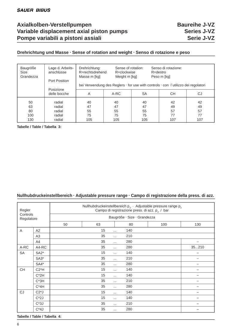
Drehrichtung und Masse . Sense of rotation and weight . Senso di rotazione e peso
6
Baugröße Lage d. Arbeits- Drehrichtung: Sense of rotation: Senso di rotazione:Size anschlüsse R=rechtsdrehend R=clockwise R=destroGrandezza Masse m [kg] Weight m [kg] Peso m [kg]
Port Positionbei Verwendung des Reglers . for use with controls . con l´utilizzo dei regolatori
Posizionedelle bocche A A-RC SA CH CJ
50 radial 40 40 40 42 4263 radial 47 47 47 49 4980 radial 55 55 55 57 57100 radial 75 75 75 77 77130 radial 105 105 105 107 107
Tabelle / Table / Tabella 3:
Tabelle / Table / Tabella 4:
ReglerControlsRegolatore
A A2
A3
A4
A-RC A4-RC
SA SA2*
SA3*
SA4*
CH C2*H
C*2H
C*3H
C*4H
CJ C2*J
C*2J
C*3J
C*4J
Nullhubdruckeinstellbereich p2 . Adjustable pressure range p2Campo di registrazione press. di azz. p2 / bar
Baugröße . Size . Grandezza
50 63 80 100 130
15 ... 140
35 ... 210
35 ... 280 –
35 ... 280 35...210
15 ... 140 –
35 ... 210 –
35 ... 280 –
15 ... 140 –
15 ... 140 –
35 ... 210 –
35 ... 280 –
15 ... 140 –
15 ... 140 –
35 ... 210 –
35 ... 280 –
Nullhubdruckeinstellbereich . Adjustable pressure range . Campo di registrazione della press. di azz.
Axialkolben-Verstellpumpen Baureihe J-VZVariable displacement axial piston pumps Series J-VZPompe variabili a pistoni assiali Serie J-VZ
Typenschlüssel bei Verwendung von . Model code . Chiave di ordinazione con l´utilizzo del
7
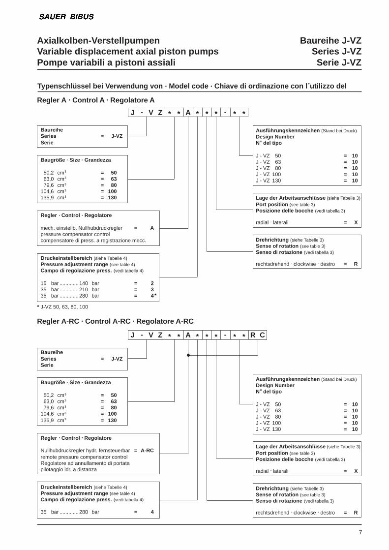
Regler A . Control A . Regolatore A
BaureiheSeries = J-VZSerie
Baugröße . Size . Grandezza
50,2 cm3 = 5063,0 cm3 = 6379,6 cm3 = 80
104,6 cm3 = 100135,9 cm3 = 130
Regler . Control . Regolatore
mech. einstellb. Nullhubdruckregler = Apressure compensator controlcompensatore di press. a registrazione mecc.
Druckeinstellbereich (siehe Tabelle 4)Pressure adjustment range (see table 4)Campo di regolazione press. (vedi tabella 4)
15 bar ............. 140 bar = 235 bar ............. 210 bar = 335 bar ............. 280 bar = 4
Ausführungskennzeichen (Stand bei Druck)Design NumberN° del tipo
J - VZ 50 = 10J - VZ 63 = 10J - VZ 80 = 10J - VZ 100 = 10J - VZ 130 = 10
Lage der Arbeitsanschlüsse (siehe Tabelle 3)Port position (see table 3)Posizione delle bocche (vedi tabella 3)
radial . laterali = X
Drehrichtung (siehe Tabelle 3)Sense of rotation (see table 3)Senso di rotazione (vedi tabella 3)
rechtsdrehend . clockwise . destro = R
J - V Z * * A * * * - * *
Regler A-RC . Control A-RC . Regolatore A-RC
BaureiheSeries = J-VZSerie
Baugröße . Size . Grandezza
50,2 cm3 = 5063,0 cm3 = 6379,6 cm3 = 80
104,6 cm3 = 100135,9 cm3 = 130
Regler . Control . Regolatore
Nullhubdruckregler hydr. fernsteuerbar = A-RCremote pressure compensator controlRegolatore ad annullamento di portatapilotaggio idr. a distanza
Druckeinstellbereich (siehe Tabelle 4)Pressure adjustment range (see table 4)Campo di regolazione press. (vedi tabella 4)
35 bar ............. 280 bar = 4
Ausführungskennzeichen (Stand bei Druck)Design NumberN° del tipo
J - VZ 50 = 10J - VZ 63 = 10J - VZ 80 = 10J - VZ 100 = 10J - VZ 130 = 10
Lage der Arbeitsanschlüsse (siehe Tabelle 3)Port position (see table 3)Posizione delle bocche (vedi tabella 3)
radial . laterali = X
Drehrichtung (siehe Tabelle 3)Sense of rotation (see table 3)Senso di rotazione (vedi tabella 3)
rechtsdrehend . clockwise . destro = R
J - V Z * * A * * * - * * R C
* J-VZ 50, 63, 80, 100
*
Axialkolben-Verstellpumpen Baureihe J-VZVariable displacement axial piston pumps Series J-VZPompe variabili a pistoni assiali Serie J-VZ
Typenschlüssel bei Verwendung von . Model code . Chiave di ordinazione con l´utilizzo del
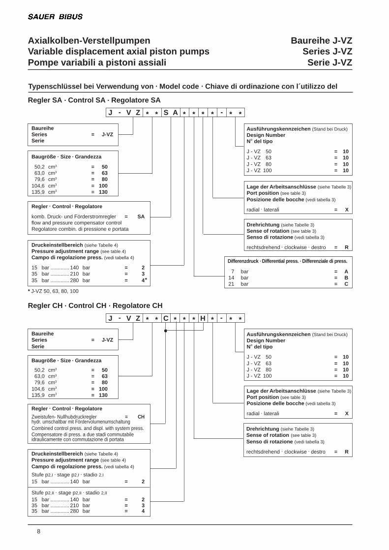
Regler SA . Control SA . Regolatore SA
BaureiheSeries = J-VZSerie
Baugröße . Size . Grandezza
50,2 cm3 = 5063,0 cm3 = 6379,6 cm3 = 80
104,6 cm3 = 100135,9 cm3 = 130
Regler . Control . Regolatore
komb. Druck- und Förderstromregler = SAflow and pressure compensator controlRegolatore combin. di pressione e portata
Druckeinstellbereich (siehe Tabelle 4)Pressure adjustment range (see table 4)Campo di regolazione press. (vedi tabella 4)
15 bar ............. 140 bar = 235 bar ............. 210 bar = 335 bar ............. 280 bar = 4
Ausführungskennzeichen (Stand bei Druck)Design NumberN° del tipo
J - VZ 50 = 10J - VZ 63 = 10J - VZ 80 = 10J - VZ 100 = 10
Lage der Arbeitsanschlüsse (siehe Tabelle 3)Port position (see table 3)Posizione delle bocche (vedi tabella 3)
radial . laterali = X
Drehrichtung (siehe Tabelle 3)Sense of rotation (see table 3)Senso di rotazione (vedi tabella 3)
rechtsdrehend . clockwise . destro = R
J - V Z * * S A * * * * - * *
Differenzdruck . Differential press. . Differenziale di press.
7 bar = A14 bar = B21 bar = C
8
Regler CH . Control CH . Regolatore CH
BaureiheSeries = J-VZSerie
Baugröße . Size . Grandezza
50,2 cm3 = 5063,0 cm3 = 6379,6 cm3 = 80
104,6 cm3 = 100135,9 cm3 = 130
Regler . Control . Regolatore
Zweistufen- Nullhubdruckregler = CHhydr. umschaltbar mit FördervolumenumschaltungCombined control press. and displ. with system press.Compensatore di press. a due stadi commutabileidraulicamente con commutazione di portata
Druckeinstellbereich (siehe Tabelle 4)Pressure adjustment range (see table 4)Campo di regolazione press. (vedi tabella 4)
Stufe p2,I . stage p2,I . stadio 2,I
15 bar ............. 140 bar = 2
Stufe p2,II . stage p2,II . stadio 2,II
15 bar ............. 140 bar = 235 bar ............. 210 bar = 335 bar ............. 280 bar = 4
Ausführungskennzeichen (Stand bei Druck)Design NumberN° del tipo
J - VZ 50 = 10J - VZ 63 = 10J - VZ 80 = 10J - VZ 100 = 10
Lage der Arbeitsanschlüsse (siehe Tabelle 3)Port position (see table 3)Posizione delle bocche (vedi tabella 3)
radial . laterali = X
J - V Z * * C * * * H * - * *
* J-VZ 50, 63, 80, 100
*
Drehrichtung (siehe Tabelle 3)Sense of rotation (see table 3)Senso di rotazione (vedi tabella 3)
rechtsdrehend . clockwise . destro = R
Axialkolben-Verstellpumpen Baureihe J-VZVariable displacement axial piston pumps Series J-VZPompe variabili a pistoni assiali Serie J-VZ
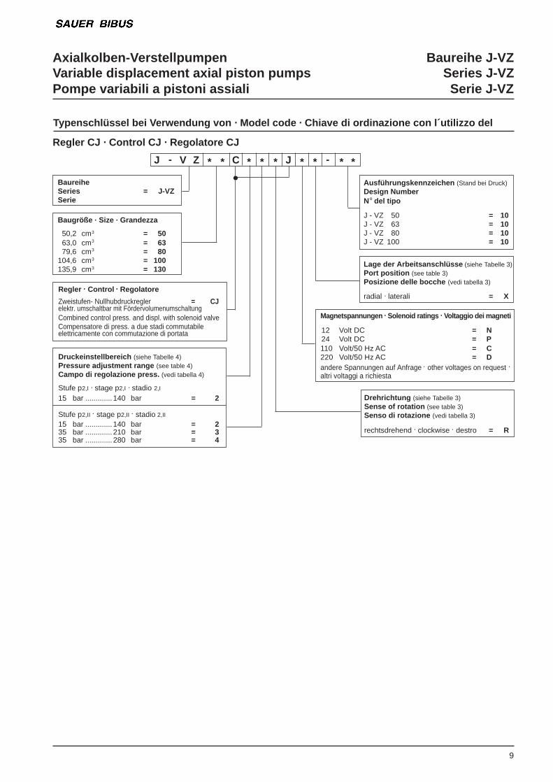
Typenschlüssel bei Verwendung von . Model code . Chiave di ordinazione con l´utilizzo del
9
Regler . Control . Regolatore
Zweistufen- Nullhubdruckregler = CJelektr. umschaltbar mit FördervolumenumschaltungCombined control press. and displ. with solenoid valveCompensatore di press. a due stadi commutabileelettricamente con commutazione di portata
Druckeinstellbereich (siehe Tabelle 4)Pressure adjustment range (see table 4)Campo di regolazione press. (vedi tabella 4)
Stufe p2,I . stage p2,I . stadio 2,I
15 bar ............. 140 bar = 2
Stufe p2,II . stage p2,II . stadio 2,II
15 bar ............. 140 bar = 235 bar ............. 210 bar = 335 bar ............. 280 bar = 4
Regler CJ . Control CJ . Regolatore CJ
BaureiheSeries = J-VZSerie
Baugröße . Size . Grandezza
50,2 cm3 = 5063,0 cm3 = 6379,6 cm3 = 80
104,6 cm3 = 100135,9 cm3 = 130
Ausführungskennzeichen (Stand bei Druck)Design NumberN° del tipo
J - VZ 50 = 10J - VZ 63 = 10J - VZ 80 = 10J - VZ 100 = 10
Lage der Arbeitsanschlüsse (siehe Tabelle 3)Port position (see table 3)Posizione delle bocche (vedi tabella 3)
radial . laterali = X
J - V Z * * C * * * J * * - * *
Magnetspannungen . Solenoid ratings . Voltaggio dei magneti
12 Volt DC = N24 Volt DC = P110 Volt/50 Hz AC = C220 Volt/50 Hz AC = Dandere Spannungen auf Anfrage . other voltages on request .
altri voltaggi a richiesta
Drehrichtung (siehe Tabelle 3)Sense of rotation (see table 3)Senso di rotazione (vedi tabella 3)
rechtsdrehend . clockwise . destro = R
Axialkolben-Verstellpumpen Baureihe J-VZVariable displacement axial piston pumps Series J-VZPompe variabili a pistoni assiali Serie J-VZ
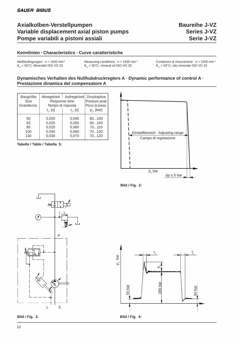
Kennlinien . Characteristics . Curve caratteristiche
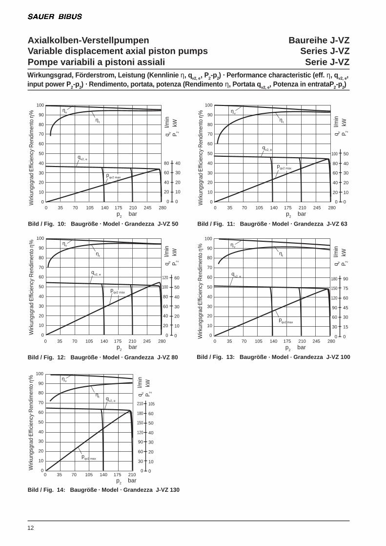
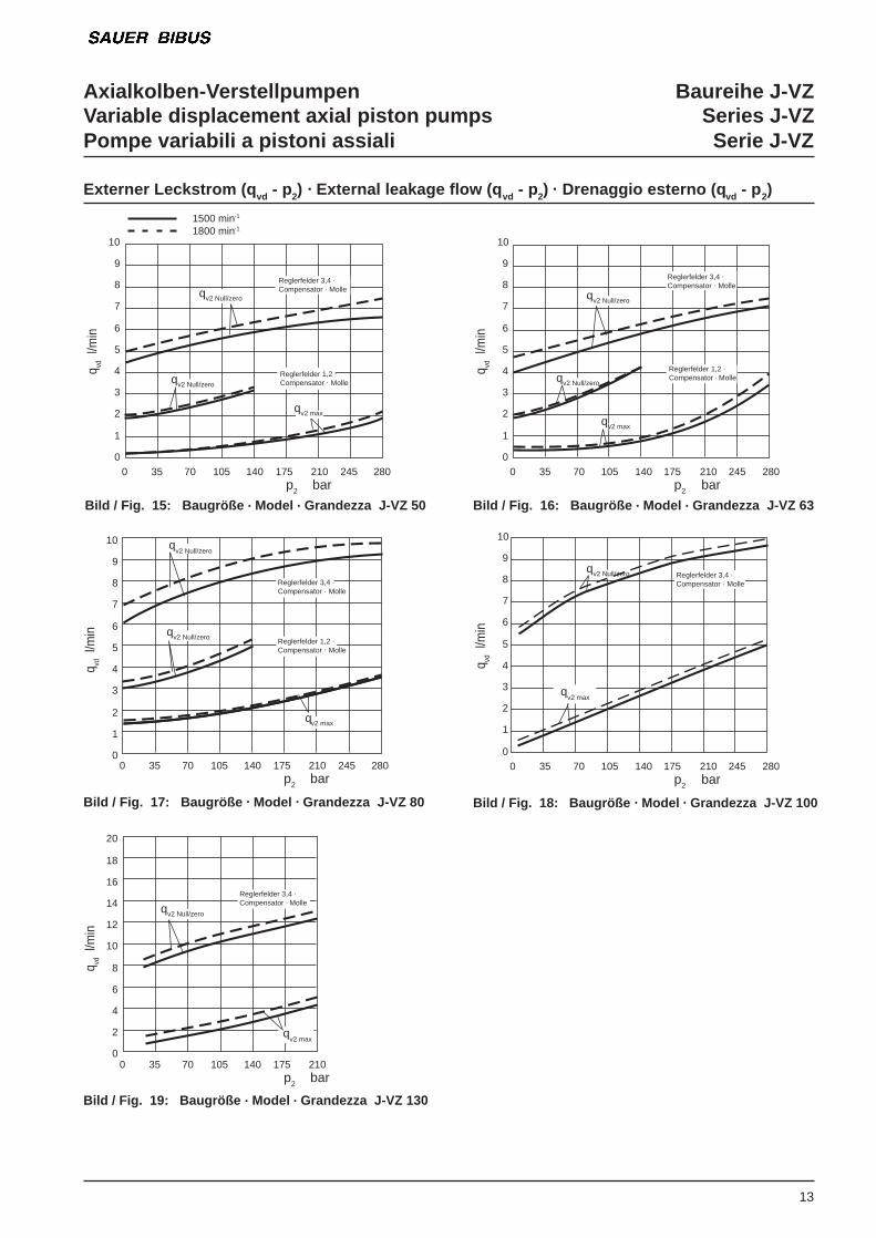
Meßbedingungen: n = 1500 min-1 Measuring conditions: n = 1500 min-1 Condizioni di misurazione: n = 1500 min-1
θ1,f = 50°C, Mineralöl ISO VG 32 θ1,f = 50°C, mineral oil ISO VG 32 θ1,f = 50°C, olio minerale ISO VG 32
Dynamisches Verhalten des Nullhubdruckreglers A . Dynamic performance of control A .Prestazione dinamica del compensatore A
Baugröße Abregelzeit Aufregelzeit DruckspitzeSize Response time Pressure peak
Grandezza Tempo di risposta Picco di press.t1, [s] t2, [s] ps, [bar]
50 0,020 0,045 60...10063 0,025 0,050 60...10080 0,025 0,060 70...110100 0,030 0,060 70...120130 0,030 0,070 70...120
Tabelle / Table / Tabella 5:
Bild / Fig. 3:
10
Bild / Fig. 4:
50 b
ar
50 b
ar
280
bar
p 2 b
ar
p s
t1 t2
Bild / Fig. 2:
P
L S
Einstellbereich . Adjusting rangeCampo di regolazione
p2 bar∆p ≤ 5 bar

Axialkolben-Verstellpumpen Baureihe J-VZVariable displacement axial piston pumps Series J-VZPompe variabili a pistoni assiali Serie J-VZ
11
Bild / Fig. 6: Baugröße . Model . Grandezza J-VZ 63
Bild / Fig. 7: Baugröße . Model . Grandezza J-VZ 80
75
70
65
60
55
500 50 100 150 200 250 280 300
p2 bar
L p
dB
(A)
75
70
65
60
55
500 50 100 150 200 250 280 300
p2 barL p
d
B(A
)
75
70
65
60
55
500 50 100 150 200 250 280 300
p2 bar
L p
dB
(A)
Bild / Fig. 5: Baugröße . Model . Grandezza J-VZ 50
Geräuschmessungen (Kennlinie Lp - p2) . Noise level (characteristic Lp - p
2) . Livello di rumorosità (curva Lp - p
2)
gemessen im Schallmeßraum, Meßabstand 1m . measured in a sound measuring room, distance 1m . misurato in camera anecoica, alla distanza di 1m
qv2 max
qv2 Null/zero
qv2 max
qv2 Null/zero
qv2 max
qv2 Null/zero
Bild / Fig. 8: Baugröße . Model . Grandezza J-VZ 100
Bild / Fig. 9: Baugröße . Model . Grandezza J-VZ 130
80
75
70
65
60
55
500 50 100 150 200 250 280 300
p2 bar
L p
dB
(A)
0 50 100 150 200 250 280 300
p2 bar
L p
dB
(A)
qv2 max
qv2 Null/zero
qv2 max
qv2 Null/zero
80
75
70
65
60
55
50
Axialkolben-Verstellpumpen Baureihe J-VZVariable displacement axial piston pumps Series J-VZPompe variabili a pistoni assiali Serie J-VZ
12
Wirkungsgrad, Förderstrom, Leistung (Kennlinie η, qv2, e, P2-p2) . Performance characteristic (eff. η, qv2, e,input power P 2-p2) . Rendimento, portata, potenza (Rendimento η, Portata q v2, e, Potenza in entrataP 2-p2)
Bild / Fig. 10: Baugröße . Model . Grandezza J-VZ 50 Bild / Fig. 11: Baugröße . Model . Grandezza J-VZ 63
Bild / Fig. 12: Baugröße . Model . Grandezza J-VZ 80
100
90
80
70
60
50
40
30
20
10
00 35 70 105 140 175 210 245 280
ηv
qv2, e
p2 bar
Wirk
ungs
grad
. Effi
cien
cy. R
endi
men
to η
%
ηt
80
60
40
20
0
40
30
20
10
0
qv
l/m
in P
2 k
W
100
90
80
70
60
50
40
30
20
10
00 35 70 105 140 175 210 245 280
ηv
qv2, e
p2 bar
Wirk
ungs
grad
. Effi
cien
cy. R
endi
men
to η
%
ηt
100
80
60
40
20
0
50
40
30
20
10
0
qv
l/m
in P
2 k
W
100
90
80
70
60
50
40
30
20
10
00 35 70 105 140 175 210 245 280
ηv
qv2, e
p2 bar
Wirk
ungs
grad
. Effi
cien
cy. R
endi
men
to η
%
ηt
120
100
80
60
40
20
0
60
50
40
30
20
10
0
qv
l/m
in P
2 k
W
pqv2 max
pqv2 max
pqv2 max
Bild / Fig. 13: Baugröße . Model . Grandezza J-VZ 100
Bild / Fig. 14: Baugröße . Model . Grandezza J-VZ 130
100
90
80
70
60
50
40
30
20
10
00 35 70 105 140 175 210 245 280
ηv
p2 bar
Wirk
ungs
grad
. Effi
cien
cy. R
endi
men
to η
%
ηt
180
150
120
90
60
30
0
90
75
60
45
30
15
0 q
v l/
min
P2
kW
100
90
80
70
60
50
40
30
20
10
00 35 70 105 140 175 210
ηv
p2 bar
Wirk
ungs
grad
. Effi
cien
cy. R
endi
men
to η
%
ηt
210
180
150
120
90
60
30
0
105
60
50
40
30
20
10
0
qv
l/m
in P
2 k
W
qv2, e
pqv2 max
qv2, e
pqv2 max
Axialkolben-Verstellpumpen Baureihe J-VZVariable displacement axial piston pumps Series J-VZPompe variabili a pistoni assiali Serie J-VZ
13
Externer Leckstrom (q vd - p2) . External leakage flow (q vd - p2) . Drenaggio esterno (q vd - p2)
Bild / Fig. 15: Baugröße . Model . Grandezza J-VZ 50 Bild / Fig. 16: Baugröße . Model . Grandezza J-VZ 63
10
9
8
7
6
5
4
3
2
1
00 35 70 105 140 175 210 245 280
p2 bar
qvd
l/m
in
1500 min-1
1800 min-1
10
9
8
7
6
5
4
3
2
1
00 35 70 105 140 175 210 245 280
p2 bar q
vd l
/min
Reglerfelder 3,4 .
Compensator . Molleqv2 Null/zero
Reglerfelder 1,2 .
Compensator . Molleqv2 Null/zero
qv2 max
qv2 Null/zero
Reglerfelder 3,4 .
Compensator . Molle
Reglerfelder 1,2 .Compensator . Molleqv2 Null/zero
qv2 max
Bild / Fig. 17: Baugröße . Model . Grandezza J-VZ 80
10
9
8
7
6
5
4
3
2
1
00 35 70 105 140 175 210 245 280
p2 bar
qvd
l/m
in qv2 Null/zero
qv2 max
qv2 Null/zero
Reglerfelder 3,4 .Compensator . Molle
Reglerfelder 1,2 .
Compensator . Molle
Bild / Fig. 18: Baugröße . Model . Grandezza J-VZ 100
10
9
8
7
6
5
4
3
2
1
00 35 70 105 140 175 210 245 280
p2 bar
qvd
l/m
in
qv2 Null/zero Reglerfelder 3,4 .Compensator . Molle
qv2 max
Bild / Fig. 19: Baugröße . Model . Grandezza J-VZ 130
20
18
16
14
12
10
8
6
4
2
00 35 70 105 140 175 210
p2 bar
qvd
l/m
in
qv2 Null/zero
qv2 max
Reglerfelder 3,4 .
Compensator . Molle

Axialkolben-Verstellpumpen Baureihe J-VZVariable displacement axial piston pumps Series J-VZPompe variabili a pistoni assiali Serie J-VZNullhubleistung (Pq
v Null - p
2) . Dead head horsepower characteristic (Pq
v zero - p
2) .
Potenza dispersa in compensazione (Pq v zero - p2)
14
Bild / Fig. 20: Baugröße . Model . Grandezza J-VZ 50
Bild / Fig. 22: Baugröße . Model . Grandezza J-VZ 80
Bild / Fig. 21: Baugröße . Model . Grandezza J-VZ 63
10
9
8
7
6
5
4
3
2
1
00 35 70 105 140 175 210 245 280
p2 bar
Pqv
Nul
l/zer
o kW
1500 min-1
1800 min-1
10
9
8
7
6
5
4
3
2
1
00 35 70 105 140 175 210 245 280
p2 bar
Pqv
Nul
l/zer
o kW
10
9
8
7
6
5
4
3
2
1
00 35 70 105 140 175 210 245 280
p2 barP
qv N
ull/z
ero
kW
Reglerfelder 3,4 .
Compensator . Molle
Reglerfelder 1,2 .Compensator . Molle
Reglerfelder 3,4 .
Compensator . Molle
Reglerfelder 1,2 .
Compensator . Molle
Reglerfelder 3,4 .
Compensator . Molle
Reglerfelder 1,2 .
Compensator . Molle
Bild / Fig. 24: Baugröße . Model . Grandezza J-VZ 130
Bild / Fig. 23: Baugröße . Model . Grandezza J-VZ 100
10
9
8
7
6
5
4
3
2
1
00 35 70 105 140 175 210
p2 bar
Pqv
Nul
l/zer
o kW
10
9
8
7
6
5
4
3
2
1
00 35 70 105 140 175 210 245 280
p2 bar
Pqv
Nul
l/zer
o kW
Reglerfelder 3,4 .
Compensator . Molle
Reglerfelder 3,4 .
Compensator . Molle
Axialkolben-Verstellpumpen Baureihe J-VZVariable displacement axial piston pumps Series J-VZPompe variabili a pistoni assiali Serie J-VZ
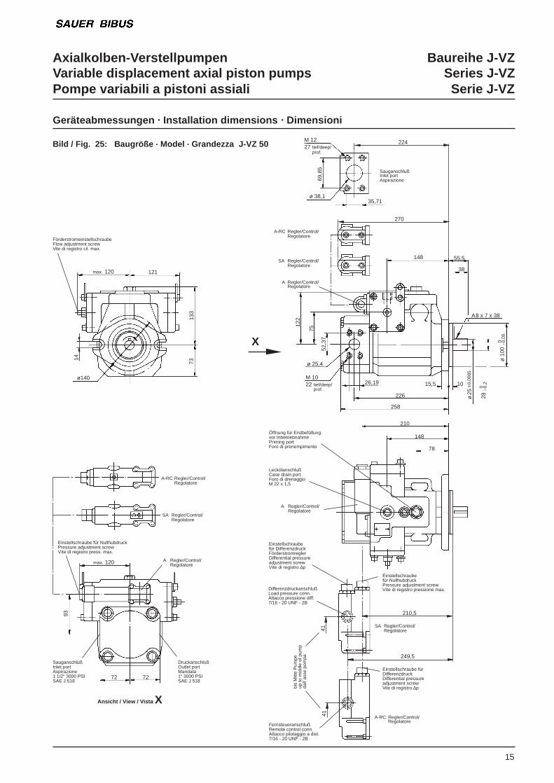
15
Geräteabmessungen . Installation dimensions . Dimensioni
Bild / Fig. 25: Baugröße . Model . Grandezza J-VZ 50M 1227 tief/deep/
prof.
35,71
69,8
5
ø 38,1
224
SauganschlußInlet portAspirazione
A-RC Regler/Control/Regolatore
SA Regler/Control/Regolatore
A Regler/Control/Regolatore
148 55,5
38
A 8 x 7 x 38
ø 1
00 0 –0
,05
28 0 –0
,2
ø 2
5±0
,006
5
1015,5
226
258
26,19M 1022 tief/deep/
prof.
ø 25,4
52,3
7
75
122
14
7313
3
max. 120 121
FörderstromeinstellschraubeFlow adjustment screwVite di registro cil. max.
72
SA Regler/Control/Regolatore
A-RC Regler/Control/Regolatore
Einstellschraube für NullhubdruckPressure adjustment screwVite di registro press. max.
max. 120 A Regler/Control/Regolatore
SauganschlußInlet portAspirazione1 1/2“ 3000 PSISAE J 518
DruckanschlußOutlet portMandata1“ 3000 PSISAE J 518
72
Öffnung für Erstbefüllungvor InbetriebnahmePriming portForo di preriempimento
210
LeckölanschlußCase drain portForo di drenaggioM 22 x 1,5
A Regler/Control/Regolatore
148
78
Einstellschraubefür DifferenzdruckFörderstromreglerDifferential pressureadjustment screwVite di registro ∆p
Einstellschraubefür NullhubdruckPressure adjustment screwVite di registro pressione max.
Einstellschraube fürDifferenzdruckDifferential pressureadjustment screwVite di registro ∆p
DifferenzdruckanschlußLoad pressure conn.Attacco pressione diff.7/16 - 20 UNF - 2B
210,5
249,5
SA Regler/Control/Regolatore
A-RC Regler/Control/Regolatore
41
FernsteueranschlußRemote control conn.Attacco pilotaggio a dist.7/16 - 20 UNF - 2B
270
bis
Mitt
e P
umpe
up to
mid
dle
of p
ump
dall´
asse
pom
pa
41
Ansicht / View / Vista X
X
93
ø140
Axialkolben-Verstellpumpen Baureihe J-VZVariable displacement axial piston pumps Series J-VZPompe variabili a pistoni assiali Serie J-VZ
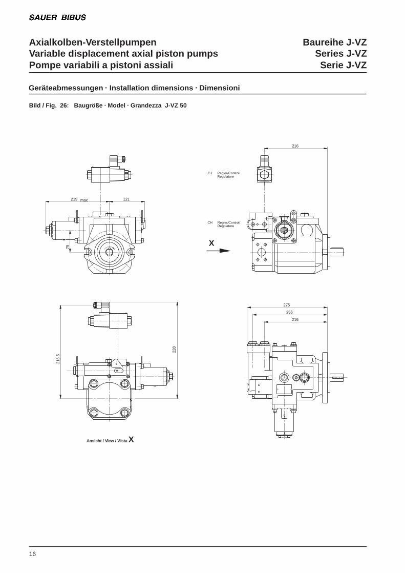
Geräteabmessungen . Installation dimensions . Dimensioni
275
256
216
75
219 max 121
216
228
216.
5
16
Bild / Fig. 26: Baugröße . Model . Grandezza J-VZ 50
Ansicht / View / Vista X
X
CJ Regler/Control/Regolatore
CH Regler/Control/ Regolatore
Axialkolben-Verstellpumpen Baureihe J-VZVariable displacement axial piston pumps Series J-VZPompe variabili a pistoni assiali Serie J-VZ
17
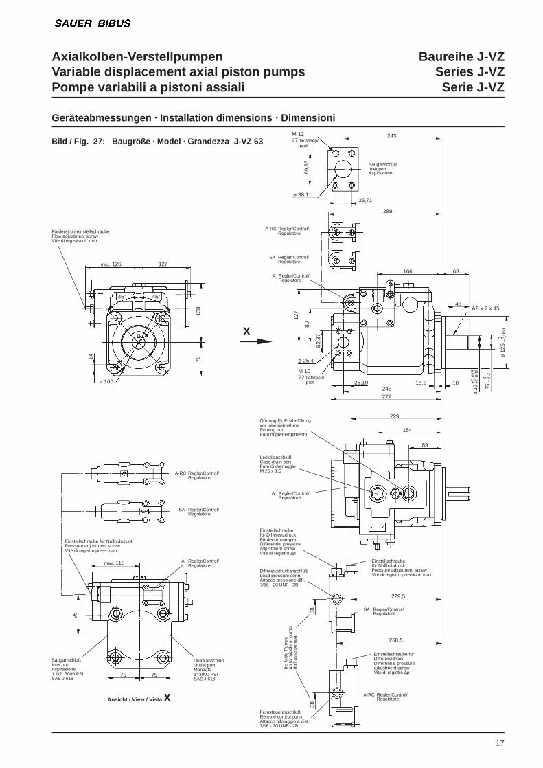
Geräteabmessungen . Installation dimensions . Dimensioni
Bild / Fig. 27: Baugröße . Model . Grandezza J-VZ 63M 1227 tief/deep/
prof.
35,71
69,8
5
ø 38,1
243
SauganschlußInlet portAspirazione
A-RC Regler/Control/Regolatore
SA Regler/Control/Regolatore
A Regler/Control/Regolatore
166 68
45A 8 x 7 x 45
ø 1
25 0 –0
,063
35 0 –0
,2
ø 3
2+
0,01
8+
0,00
2
1016,5245277
26,19
M 1022 tief/deep/
prof.
ø 25,4
52,3
7
80
127
14 7813
8
ø 160
max. 126 127
FörderstromeinstellschraubeFlow adjustment screwVite di registro cil. max.
75
SA Regler/Control/Regolatore
A-RC Regler/Control/Regolatore
Einstellschraube für NullhubdruckPressure adjustment screwVite di registro press. max.
max. 118 A Regler/Control/Regolatore
SauganschlußInlet portAspirazione1 1/2“ 3000 PSISAE J 518
DruckanschlußOutlet portMandata1“ 3000 PSISAE J 518
75
Öffnung für Erstbefüllungvor InbetriebnahmePriming portForo di preriempimento
229
LeckölanschlußCase drain portForo di drenaggioM 26 x 1,5
A Regler/Control/Regolatore
164
89
Einstellschraubefür DifferenzdruckFörderstromreglerDifferential pressureadjustment screwVite di registro ∆p
Einstellschraubefür NullhubdruckPressure adjustment screwVite di registro pressione max.
Einstellschraube fürDifferenzdruckDifferential pressureadjustment screwVite di registro ∆p
DifferenzdruckanschlußLoad pressure conn.Attacco pressione diff.7/16 - 20 UNF - 2B
229,5
268,5
SA Regler/Control/Regolatore
A-RC Regler/Control/Regolatore
38
FernsteueranschlußRemote control conn.Attacco pilotaggio a dist.7/16 - 20 UNF - 2B
289
bis
Mitt
e P
umpe
up to
mid
dle
of p
ump
dall´
asse
pom
pa
38
X
45°45°
95
Ansicht / View / Vista X
Axialkolben-Verstellpumpen Baureihe J-VZVariable displacement axial piston pumps Series J-VZPompe variabili a pistoni assiali Serie J-VZ
18
Geräteabmessungen . Installation dimensions . Dimensioni
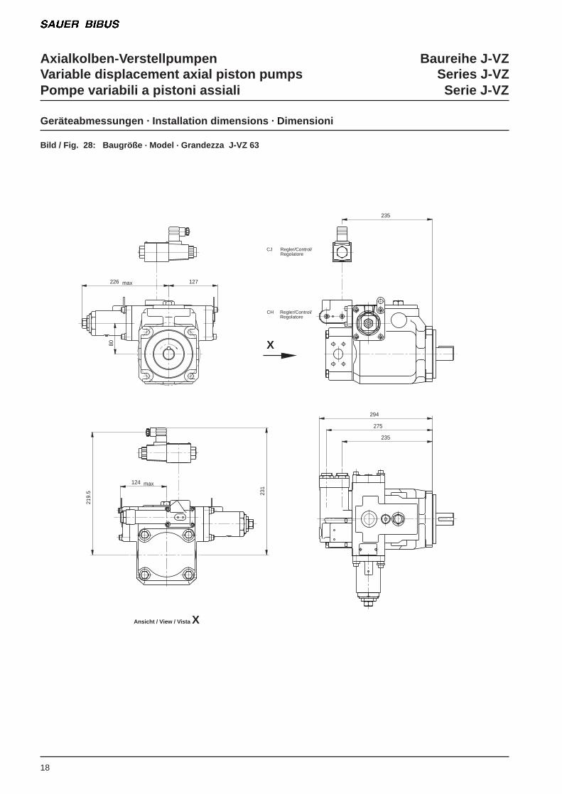
Bild / Fig. 28: Baugröße . Model . Grandezza J-VZ 63
219.
5 231
294
275
235
80
max226 127
max124
235
CJ Regler/Control/Regolatore
CH Regler/Control/ Regolatore
X
Ansicht / View / Vista X
Axialkolben-Verstellpumpen Baureihe J-VZVariable displacement axial piston pumps Series J-VZPompe variabili a pistoni assiali Serie J-VZ
19
Geräteabmessungen . Installation dimensions . Dimensioni
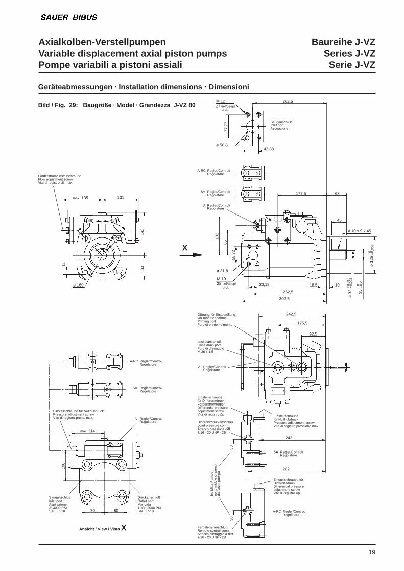
Bild / Fig. 29: Baugröße . Model . Grandezza J-VZ 80M 1227 tief/deep/ prof.
42,88
77,7
7
ø 50,8
262,5
SauganschlußInlet portAspirazione
A-RC Regler/Control/Regolatore
SA Regler/Control/Regolatore
A Regler/Control/Regolatore
177,5 68
45
A 10 x 9 x 45
ø 1
25 0 –0
,063
35 0 –0
,2
ø 3
2+
0,01
8+
0,00
2
1018,5
262,5
302,5
30,18M 1028 tief/deep/
prof.
ø 31,8
58,7
2
85
132
14
8314
3
ø 160
max. 135 131
FörderstromeinstellschraubeFlow adjustment screwVite di registro cil. max.
80
SA Regler/Control/Regolatore
A-RC Regler/Control/Regolatore
Einstellschraube für NullhubdruckPressure adjustment screwVite di registro press. max.
max. 114
A Regler/Control/Regolatore
SauganschlußInlet portAspirazione2“ 3000 PSISAE J 518
DruckanschlußOutlet portMandata1 1/4“ 3000 PSISAE J 51880
100
Öffnung für Erstbefüllungvor InbetriebnahmePriming portForo di preriempimento
242,5
LeckölanschlußCase drain portForo di drenaggioM 26 x 1,5
A Regler/Control/Regolatore
175,5
92,5
Einstellschraubefür DifferenzdruckFörderstromreglerDifferential pressureadjustment screwVite di registro ∆p Einstellschraube
für NullhubdruckPressure adjustment screwVite di registro pressione max.
Einstellschraube fürDifferenzdruckDifferential pressureadjustment screwVite di registro ∆p
DifferenzdruckanschlußLoad pressure conn.Attacco pressione diff.7/16 - 20 UNF - 2B
243
282
SA Regler/Control/Regolatore
A-RC Regler/Control/Regolatore
38
FernsteueranschlußRemote control conn.Attacco pilotaggio a dist.7/16 - 20 UNF - 2B
38
bis
Mitt
e P
umpe
up to
mid
dle
of p
ump
dall´
asse
pom
pa45°45°
Ansicht / View / Vista X
X
Axialkolben-Verstellpumpen Baureihe J-VZVariable displacement axial piston pumps Series J-VZPompe variabili a pistoni assiali Serie J-VZ
20
Geräteabmessungen . Installation dimensions . Dimensioni
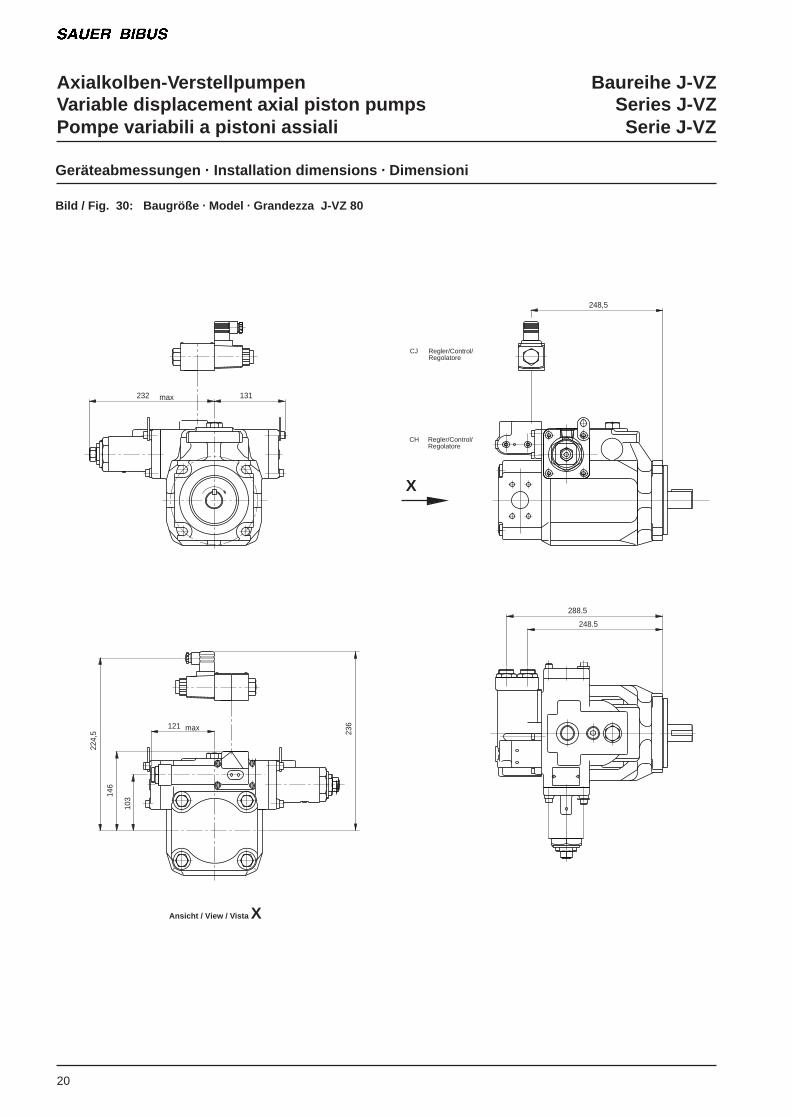
Bild / Fig. 30: Baugröße . Model . Grandezza J-VZ 80
224,
5 236
max232 131
248.5
288.5
146
103
max121
248,5
CJ Regler/Control/Regolatore
CH Regler/Control/ Regolatore
X
Ansicht / View / Vista X
Axialkolben-Verstellpumpen Baureihe J-VZVariable displacement axial piston pumps Series J-VZPompe variabili a pistoni assiali Serie J-VZ
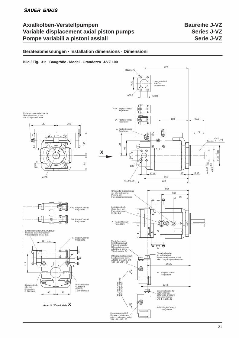
21
Geräteabmessungen . Installation dimensions . Dimensioni
Bild / Fig. 31: Baugröße . Model . Grandezza J-VZ 100
145
157
M12x1.75
ø44
.45
0 -0.0
5
138
-0.0
63 0
M12x1.75
115
38
294,5
255,5
38
255
168
95
45°45°
92
ø160
ø1‚
S
CW
150
ø30
274
318
30.18
49.3
12.4517
+0.1
3
92
58.7
2
ø12
5
x73
274
77.7
7
42.88
99.5188
73
0ø11,11+0,025
ø50.8
9090
max114
SauganschlußInlet portAspirazione
A-RC Regler/Control/Regolatore
SA Regler/Control/Regolatore
A Regler/Control/Regolatore
FörderstromeinstellschraubeFlow adjustment screwVite di registro cil. max.
SA Regler/Control/Regolatore
A-RC Regler/Control/Regolatore
Einstellschraube für NullhubdruckPressure adjustment screwVite di registro press. max.
A Regler/Control/Regolatore
SauganschlußInlet portAspirazione2“ Standard
DruckanschlußOutlet portMandata1 1/4“ Standard
Öffnung für Erstbefüllungvor InbetriebnahmePriming portForo di preriempimento
LeckölanschlußCase drain portForo di drenaggioM 26 x 1,5
A Regler/Control/Regolatore
Einstellschraubefür DifferenzdruckFörderstromreglerDifferential pressureadjustment screwVite di registro ∆p
Einstellschraubefür NullhubdruckPressure adjustment screwVite di registro pressione max.
Einstellschraube fürDifferenzdruckDifferential pressureadjustment screwVite di registro ∆p
DifferenzdruckanschlußLoad pressure conn.Attacco pressione diff.7/16 - 20 UNF - 2B
SA Regler/Control/Regolatore
A-RC Regler/Control/Regolatore
FernsteueranschlußRemote control conn.Attacco pilotaggio a dist.7/16 - 20 UNF - 2B
bis
Mitt
e P
umpe
up to
mid
dle
of p
ump
dall´
asse
pom
pa
X
Ansicht / View / Vista X
Axialkolben-Verstellpumpen Baureihe J-VZVariable displacement axial piston pumps Series J-VZPompe variabili a pistoni assiali Serie J-VZ
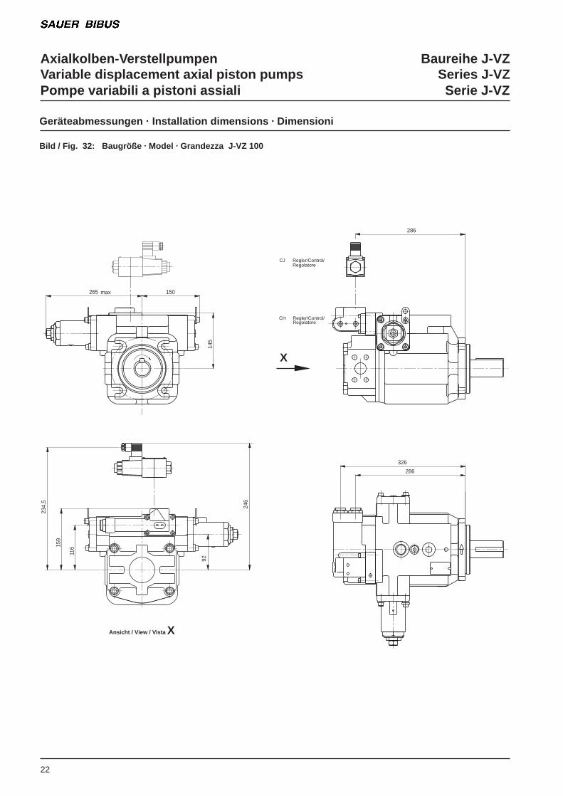
22
Geräteabmessungen . Installation dimensions . Dimensioni
Bild / Fig. 32: Baugröße . Model . Grandezza J-VZ 100
145
max 150
286
326
234,
5
11615
9
246
92
265
286
CJ Regler/Control/Regolatore
CH Regler/Control/ Regolatore
X
Ansicht / View / Vista X
Axialkolben-Verstellpumpen Baureihe J-VZVariable displacement axial piston pumps Series J-VZPompe variabili a pistoni assiali Serie J-VZ
178
50
325
325
35.71
377
100
69.8
5
149
50.80
ø63.5
88.9
49.3 +0.13
12.4524
ø15
2.40
ø15
2.35
99.5225
73
ø38.1
198.
010
0
80.8
+0.4
ø21
.3 80.8 80.8
80.8
155165
9595
149
327
217
310
124
-0.05ø44.450
ø11,11 0+0,025 x73
0
23
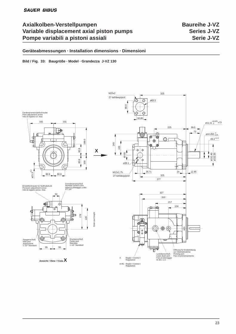
Geräteabmessungen . Installation dimensions . Dimensioni
Bild / Fig. 33: Baugröße . Model . Grandezza J-VZ 130
Einstellschraube für NullhubdruckPressure adjustment screwVite di registro press. max.
FernsteueranschlußRemote control conn.Attacco pilotaggio a dist.PT 1/4“
DruckanschlußOutlet portMandata1 1/2“ Standard
SauganschlußInlet portAspirazione2 1/2“ Standard
FörderstromeinstellschraubeFlow adjustment screwVite di registro cil. max.
A Regler / Control /Regolatore
A-RC Regler / Control /Regolatore
Dra
in p
ort h
eigh
tM20x2
27 tief/deep/prof.
M12x1,75
27 tief/deep/prof.
Öffnung für Erstbefüllungvor InbetriebnahmePriming portForo di preriempimento
LeckölanschlußCase drain portForo di drenaggioM 26 x 1,5
X
Ansicht / View / Vista X
Axialkolben-Verstellpumpen Baureihe J-VZVariable displacement axial piston pumps Series J-VZPompe variabili a pistoni assiali Serie J-VZ
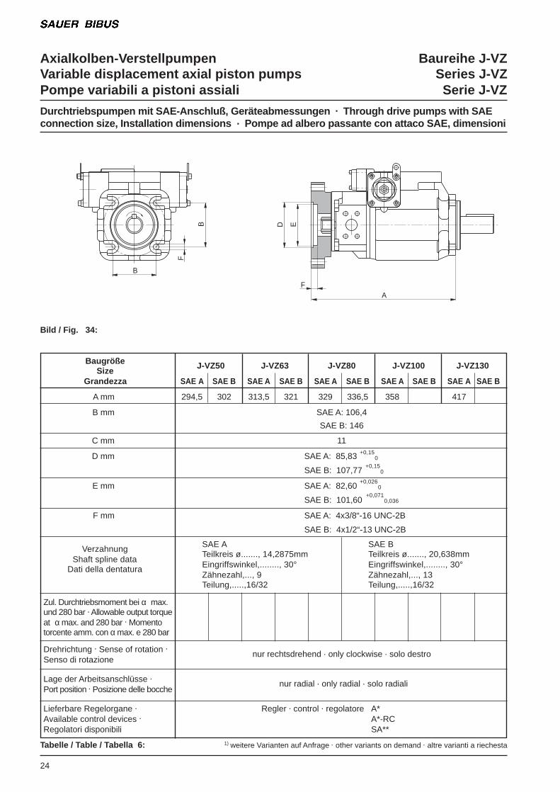
24
Durchtriebspumpen mit SAE-Anschluß, Geräteabmessungen . Through drive pumps with SAEconnection size, Installation dimensions . Pompe ad albero passante con attaco SAE, dimensioni
Bild / Fig. 34:
Tabelle / Table / Tabella 6: 1) weitere Varianten auf Anfrage . other variants on demand . altre varianti a riechesta
Zul. Durchtriebsmoment bei α max.und 280 bar . Allowable output torqueat α max. and 280 bar . Momentotorcente amm. con α max. e 280 bar
Drehrichtung . Sense of rotation . nur rechtsdrehend . only clockwise . solo destro
Senso di rotazione
Lage der Arbeitsanschlüsse . nur radial . only radial . solo radiali
Port position . Posizione delle bocche
Lieferbare Regelorgane . Regler . control . regolatore A*Available control devices . A*-RCRegolatori disponibili SA**
BaugrößeSize
J-VZ50 J-VZ63 J-VZ80 J-VZ100 J-VZ130
Grandezza SAE A SAE B SAE A SAE B SAE A SAE B SAE A SAE B SAE A SAE B
A mm 294,5 302 313,5 321 329 336,5 358 417
B mm SAE A: 106,4
SAE B: 146
C mm 11
D mm SAE A: 85,83
SAE B: 107,77
E mm SAE A: 82,60
SAE B: 101,60
F mm SAE A: 4x3/8“-16 UNC-2B
SAE B: 4x1/2“-13 UNC-2B
VerzahnungShaft spline data
Dati della dentatura
B
F
BD E
FA
SAE ATeilkreis ø......., 14,2875mmEingriffswinkel,........, 30°Zähnezahl,..., 9Teilung,.....,16/32
SAE BTeilkreis ø......., 20,638mmEingriffswinkel,........, 30°Zähnezahl,..., 13Teilung,.....,16/32
+0,15 0
+0,15 0
+0,026 0
+0,071 0,036
SAUER BIBUS Serviceweltweit ...
Der weltweite Fertigungs- und EntwicklungsverbundSAUER DANFOSS für Europa, Afrika und denNahen Osten. SAUER DANFOSS in den USA fürdie amerikanische Hemisphäre und DAIKIN inJapan für den ostasiatischen Raum, ermöglicht esSAUER BIBUS, in fast allen Ländern der WeltService zu bieten.
SAUER BIBUS Serviceworldwide ...
Thanks to the worldwide manufacturing anddevelopment cooperation between SAUERDANFOSS for Europe, Africa and the Near East,SAUER DANFOSS in the US for the Americanhemisphere and DAIKIN in Japan for the Far East.SAUER BIBUS is able to offer service factilities inalmost every country in the world.
Assistenza SAUER BIBUSnel mondo ...
Grazie agli stabilimenti produttivi sparsi nel mondoe alla cooperazione nella ricerca tra SAUERDANFOSS per l´Europa, Africa e Medio Oriente,SAUER DANFOSS negli USA per l´emisferoAmericano e DAIKIN in Giappone per l´estremooriente, la SAUER BIBUS è in grado di offrire unservizio assistenza in quasi tutti i paesi del mondo.
Axialkolben-Verstellpumpen J-V / J-HVVariable Displacement Axial Piston Pumps J-V / J-HV
Pompe variabili a pistoni assiali J-V / J-HV
Axialkolben-Verstellpumpen J-VZVariable Displacement Axial Piston Pumps J-VZ
Pompe variabili a pistoni assiali J-VZ
ProportionalventileProportional Control Valves
Valvole proporzionali
Agenzia ItaliaTelefono: +39 (0) 51 / 7094711Fax: +39 (0) 51 / 701386e-mail: [email protected]
J - VZ 08/02 . 100015
Rotorpumpen J-RPRotor Pumps J-RPRoto Pompe J-RP
ZwischenplattenventileMulti-Stack-Valves
Valvole modulari
WegeventileDirectional Control Valves
Elettrovalvole
Misprint, errors and contents are subject to technicalchanges without notice.
Druckfehler, Irrtümer und Technische Änderungenvorbehalten
Questo testo è valido salvo errori di stampa e svisteed è soggetto a cambiamenti tecnici.
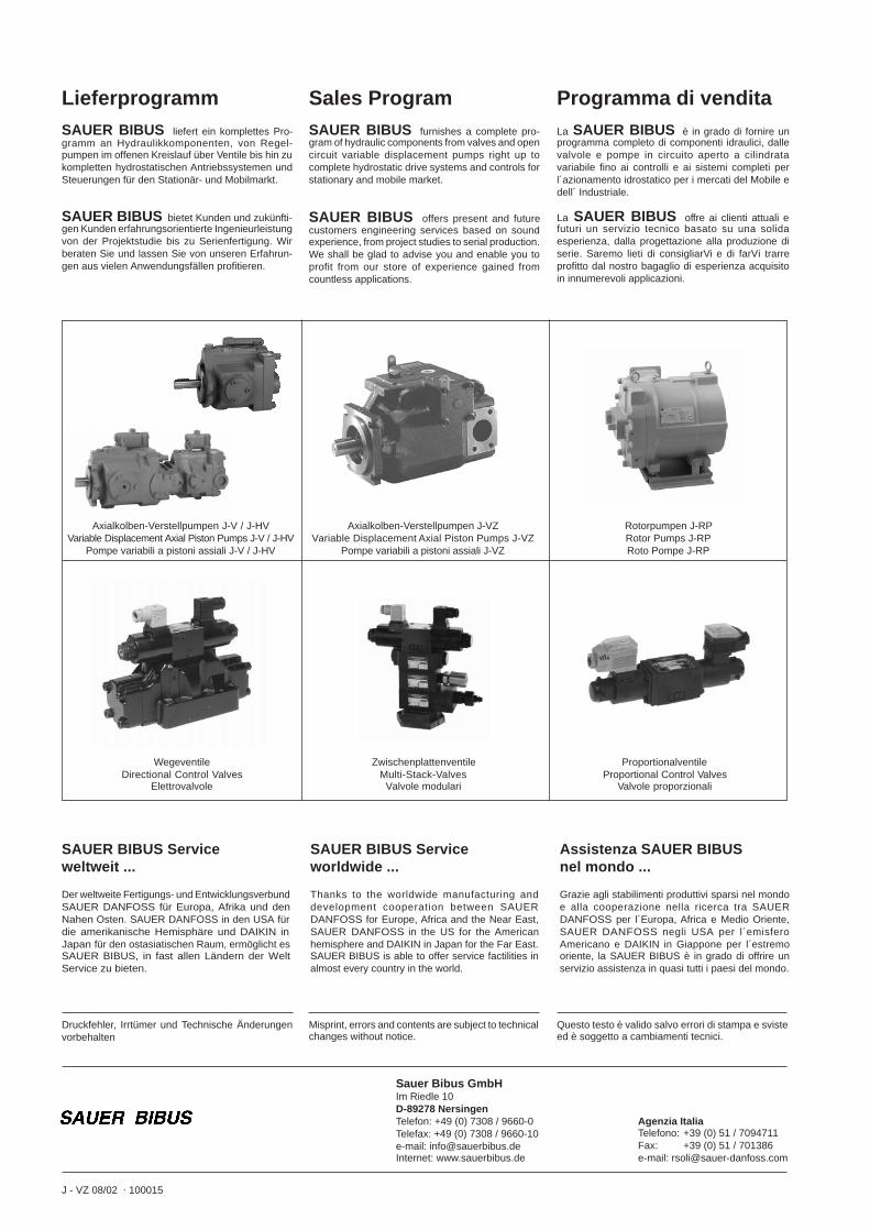
Sales ProgramSAUER BIBUS furnishes a complete pro-gram of hydraulic components from valves and opencircuit variable displacement pumps right up tocomplete hydrostatic drive systems and controls forstationary and mobile market.
SAUER BIBUS offers present and futurecustomers engineering services based on soundexperience, from project studies to serial production.We shall be glad to advise you and enable you toprofit from our store of experience gained fromcountless applications.
Programma di venditaLa SAUER BIBUS è in grado di fornire unprogramma completo di componenti idraulici, dallevalvole e pompe in circuito aperto a cilindratavariabile fino ai controlli e ai sistemi completi perl´azionamento idrostatico per i mercati del Mobile edell´ Industriale.
La SAUER BIBUS offre ai clienti attuali efuturi un servizio tecnico basato su una solidaesperienza, dalla progettazione alla produzione diserie. Saremo lieti di consigliarVi e di farVi trarreprofitto dal nostro bagaglio di esperienza acquisitoin innumerevoli applicazioni.
LieferprogrammSAUER BIBUS liefert ein komplettes Pro-gramm an Hydraulikkomponenten, von Regel-pumpen im offenen Kreislauf über Ventile bis hin zukompletten hydrostatischen Antriebssystemen undSteuerungen für den Stationär- und Mobilmarkt.
SAUER BIBUS bietet Kunden und zukünfti-gen Kunden erfahrungsorientierte Ingenieurleistungvon der Projektstudie bis zu Serienfertigung. Wirberaten Sie und lassen Sie von unseren Erfahrun-gen aus vielen Anwendungsfällen profitieren.
Sauer Bibus GmbHIm Riedle 10D-89278 NersingenTelefon: +49 (0) 7308 / 9660-0Telefax: +49 (0) 7308 / 9660-10e-mail: [email protected]: www.sauerbibus.de