Bauart / Type: PneumatiSChe StellantRiebe / DoPPeltwiRkenD ... · gen ist die richtige Wahl der...
7
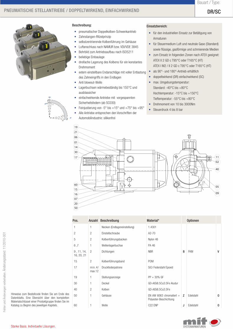
DR/SC PneumatiSChe StellantRiebe / DoPPeltwiRkenD, einfaChwiRkenD Bauart / Type: Fehler und Änderungen vorbehalten. Änderungsstand: 11/2010-001 Starke Basis. Individuelle Lösungen. einsatzbereich: • für den industriellen Einsatz zur Betätigung von Armaturen • für Steuermedium Luft und neutrale Gase (Standard) sowie flüssige, gasförmige und schmierende Medien • zum Einsatz in folgenden Zonen nach ATEX geeignet: ATEX II 2 GD c T95°C oder T165°C (HT) ATEX I M2 / II 2 GD c T95°C oder T165°C (HT) • als 90°- und 180°-Antrieb erhältlich • doppeltwirkend (DR) einfachwirkend (SC) • max. Umgebungstemperatur: Standard: -40°C bis +80°C Hochtemperatur: -15°C bis +150°C Tieftemperatur: -55°C bis +80°C • Drehmoment von 10 bis 3000Nm • Steuerdruck 4 bis 8 bar beschreibung: • pneumatischer Doppelkolben-Schwenkantrieb • Zahnstangen-Ritzelprinzip • selbstzentrierende Kolbenführung im Gehäuse • Luftanschluss nach NAMUR bzw. VDI/VDE 3845 • Bohrbild zum Antriebsaufbau nach ISO5211 • beliebige Einbaulage • dreifache Lagerung des Kolbens für ein konstantes Drehmoment • extern einstellbare Endanschläge mit voller Entlastung des Zahneingriffs in den Endlagen • Anti blowout-Welle • Lagerbuchsen wärmebeständig bis 155°C und ausblassicher • einfachwirkende Antriebe mit vorgespannten Sicherheitsfedern (ab SC030) • Feinjustierung von -5° bis +15° und +75° bis +95° • Alle Antriebe entsprechen den Vorschriften der Automobilindustrie: silikonfrei Hinweise zum Bestellcode finden Sie am Ende des Datenblatts. Eine Übersicht über den kompletten Materialschlüssel einer Produktgruppe finden Sie im Katalog zu Beginn des jeweiligen Kapitels. Pos. anzahl beschreibung material* optionen 1 1 Nocken (Endlageneinstellung) 1.4301 2 2 Einstellschraube A2-70 5 2 Kolbenführungsbacken Nylon 46 6 ,7 1 Wellenlagerbuchse PA 46 9 , 11, 14, 16, 20, 21 2 Dichtungen NBR b FKM V 15 2 Kolbenführungsband POM 17 min.4/ max.12 Druckfederpatrone SiCr Federstahl Epoxid 19 1 Stellungsanzeige PP + 30% GF 30 1 Deckel GD-AlSi8.5Cu3.5Fe Aludur 40 2 Kolben GD-AlSi8.5Cu3.5Fe 50 1 Gehäuse EN AW 6063 chromatiert + Polyester-Beschichtung Z Edelstahl o 60 1 Welle C22 ENP J Edelstahl o 02 30 06 17 15 16 14 50 40 11 05 09 07 20 60 21 19 01
Transcript of Bauart / Type: PneumatiSChe StellantRiebe / DoPPeltwiRkenD ... · gen ist die richtige Wahl der...
DR/SCPneumatiSChe StellantRiebe / DoPPeltwiRkenD, einfaChwiRkenD
Bauart / Type:Fe
hler
und
Änd
erun
gen
vorb
ehal
ten.
Änd
erun
gsst
and:
11/
2010
-001
Starke Basis. Individuelle Lösungen.
einsatzbereich:
• für den industriellen Einsatz zur Betätigung von
Armaturen
• für Steuermedium Luft und neutrale Gase (Standard)
sowie flüssige, gasförmige und schmierende Medien
• zum Einsatz in folgenden Zonen nach ATEX geeignet:
ATEX II 2 GD c T95°C oder T165°C (HT)
ATEX I M2 / II 2 GD c T95°C oder T165°C (HT)
• als 90°- und 180°-Antrieb erhältlich
• doppeltwirkend (DR) einfachwirkend (SC)
• max. Umgebungstemperatur:
Standard: -40°C bis +80°C
Hochtemperatur: -15°C bis +150°C
Tieftemperatur: -55°C bis +80°C
• Drehmoment von 10 bis 3000Nm
• Steuerdruck 4 bis 8 bar
beschreibung:
• pneumatischer Doppelkolben-Schwenkantrieb
• Zahnstangen-Ritzelprinzip
• selbstzentrierende Kolbenführung im Gehäuse
• Luftanschluss nach NAMUR bzw. VDI/VDE 3845
• Bohrbild zum Antriebsaufbau nach ISO5211
• beliebige Einbaulage
• dreifache Lagerung des Kolbens für ein konstantes
Drehmoment
• extern einstellbare Endanschläge mit voller Entlastung
des Zahneingriffs in den Endlagen
• Anti blowout-Welle
• Lagerbuchsen wärmebeständig bis 155°C und
ausblassicher
• einfachwirkende Antriebe mit vorgespannten
Sicherheitsfedern (ab SC030)
• Feinjustierung von -5° bis +15° und +75° bis +95°
• Alle Antriebe entsprechen den Vorschriften der
Automobilindustrie: silikonfrei
Hinweise zum Bestellcode finden Sie am Ende des Datenblatts. Eine Übersicht über den kompletten Materialschlüssel einer Produktgruppe finden Sie im Katalog zu Beginn des jeweiligen Kapitels.
Pos. anzahl beschreibung material* optionen
1 1 Nocken (Endlageneinstellung) 1.4301
2 2 Einstellschraube A2-70
5 2 Kolbenführungsbacken Nylon 46
6 ,7 1 Wellenlagerbuchse PA 46
9 , 11, 14, 16, 20, 21
2 Dichtungen NBR b FKM V
15 2 Kolbenführungsband POM
17 min.4/max.12
Druckfederpatrone SiCr Federstahl Epoxid
19 1 Stellungsanzeige PP + 30% GF
30 1 Deckel GD-AlSi8.5Cu3.5Fe Aludur
40 2 Kolben GD-AlSi8.5Cu3.5Fe
50 1 Gehäuse EN AW 6063 chromatiert + Polyester-Beschichtung
Z Edelstahl o
60 1 Welle C22 ENP J Edelstahl o
02
30
06
17
15
16
14
50
40
11
05
09
07
20
60
21
19
01
DR/SCPneumatiSChe StellantRiebe / DoPPeltwiRkenD, einfaChwiRkenD
Bauart / Type:Fe
hler
und
Änd
erun
gen
vorb
ehal
ten.
Änd
erun
gsst
and:
11/
2010
-001
Starke Basis. Individuelle Lösungen.
H1
L B1
H2
B2
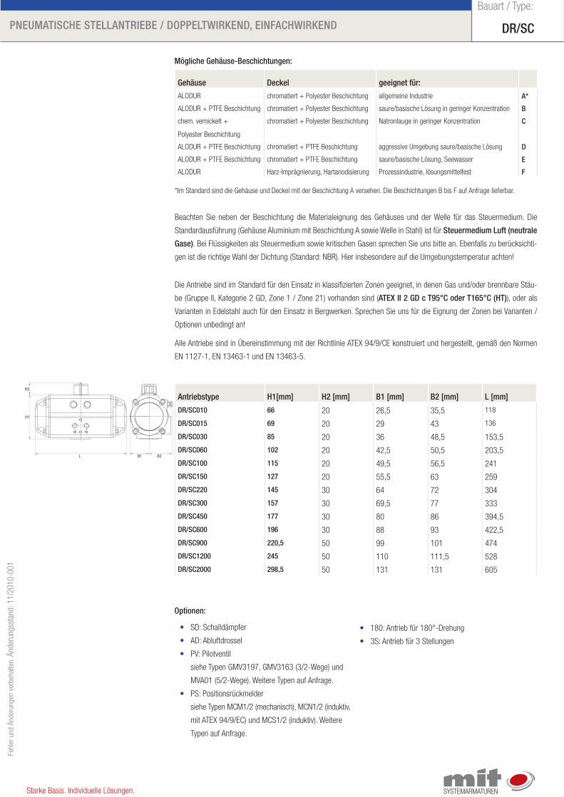
Gehäuse Deckel geeignet für:
ALODUR chromatiert + Polyester Beschichtung allgemeine Industrie a*
ALODUR + PTFE Beschichtung chromatiert + Polyester Beschichtung saure/basische Lösung in geringer Konzentration b
chem. vernickelt +
Polyester Beschichtung
chromatiert + Polyester Beschichtung Natronlauge in geringer Konzentration C
ALODUR + PTFE Beschichtung chromatiert + PTFE Beschichtung aggressive Umgebung saure/basische Lösung D
ALODUR + PTFE Beschichtung chromatiert + PTFE Beschichtung saure/basische Lösung, Seewasser e
ALODUR Harz-Imprägnierung, Hartanodisierung Prozessindustrie, lösungsmittelfest f
optionen:
• SD: Schalldämpfer
• AD: Abluftdrossel
• PV: Pilotventil
siehe Typen GMV3197, GMV3163 (3/2-Wege) und
MVA01 (5/2-Wege). Weitere Typen auf Anfrage.
• PS: Positionsrückmelder
siehe Typen MCM1/2 (mechanisch), MCN1/2 (induktiv,
mit ATEX 94/9/EC) und MCS1/2 (induktiv). Weitere
Typen auf Anfrage.
• 180: Antrieb für 180°-Drehung
• 3S: Antrieb für 3 Stellungen
mögliche Gehäuse-beschichtungen:
antriebstype h1[mm] h2 [mm] b1 [mm] b2 [mm] l [mm]
DR/SC010 66 20 26,5 35,5 118
DR/SC015 69 20 29 43 136
DR/SC030 85 20 36 48,5 153,5
DR/SC060 102 20 42,5 50,5 203,5
DR/SC100 115 20 49,5 56,5 241
DR/SC150 127 20 55,5 63 259
DR/SC220 145 30 64 72 304
DR/SC300 157 30 69,5 77 333
DR/SC450 177 30 80 86 394,5
DR/SC600 196 30 88 93 422,5
DR/SC900 220,5 50 99 101 474
DR/SC1200 245 50 110 111,5 528
DR/SC2000 298,5 50 131 131 605
*Im Standard sind die Gehäuse und Deckel mit der Beschichtung A versehen. Die Beschichtungen B bis F auf Anfrage lieferbar.
Beachten Sie neben der Beschichtung die Materialeignung des Gehäuses und der Welle für das Steuermedium. Die
Standardausführung (Gehäuse Aluminium mit Beschichtung A sowie Welle in Stahl) ist für Steuermedium luft (neutrale
Gase). Bei Flüssigkeiten als Steuermedium sowie kritischen Gasen sprechen Sie uns bitte an. Ebenfalls zu berücksichti-
gen ist die richtige Wahl der Dichtung (Standard: NBR). Hier insbesondere auf die Umgebungstemperatur achten!
Die Antriebe sind im Standard für den Einsatz in klassifizierten Zonen geeignet, in denen Gas und/oder brennbare Stäu-
be (Gruppe II, Kategorie 2 GD, Zone 1 / Zone 21) vorhanden sind (ateX ii 2 GD c t95°C oder t165°C (ht)), oder als
Varianten in Edelstahl auch für den Einsatz in Bergwerken. Sprechen Sie uns für die Eignung der Zonen bei Varianten /
Optionen unbedingt an!
Alle Antriebe sind in Übereinstimmung mit der Richtlinie ATEX 94/9/CE konstruiert und hergestellt, gemäß den Normen
EN 1127-1, EN 13463-1 und EN 13463-5.
DR/SCPneumatiSChe StellantRiebe / DoPPeltwiRkenD, einfaChwiRkenD
Bauart / Type:Fe
hler
und
Änd
erun
gen
vorb
ehal
ten.
Änd
erun
gsst
and:
11/
2010
-001
Starke Basis. Individuelle Lösungen.
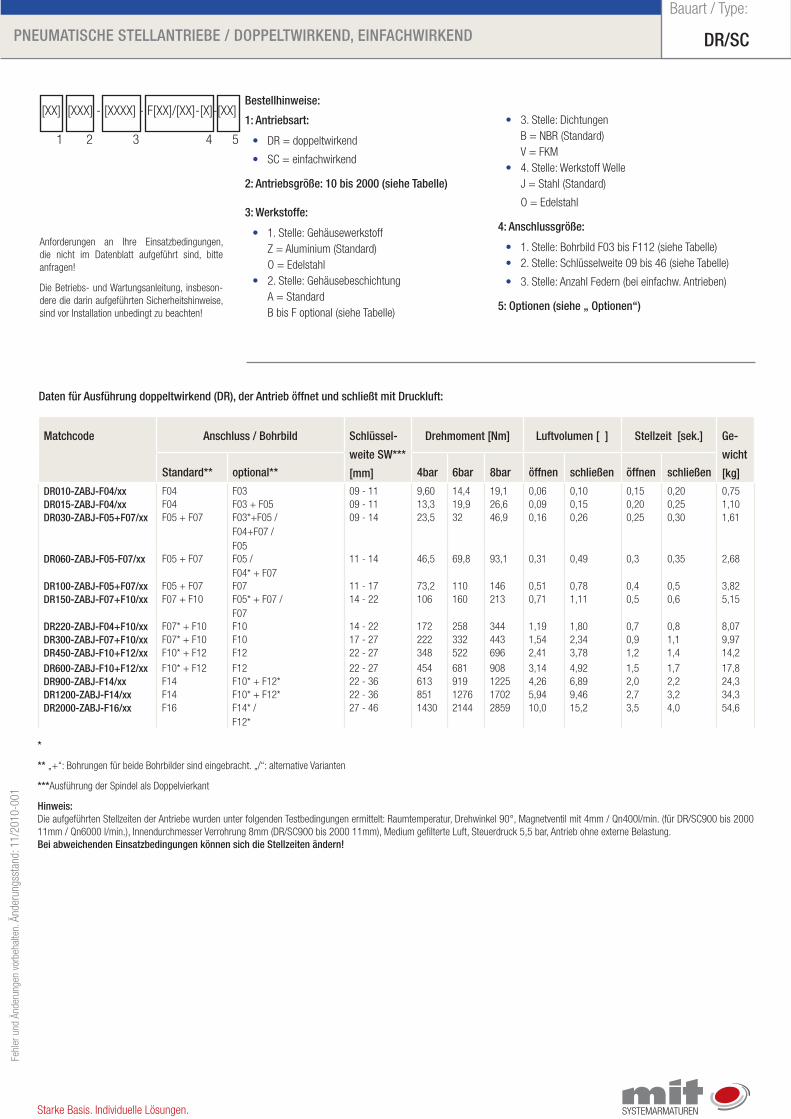
matchcode anschluss / bohrbild Schlüssel-
weite Sw***
[mm]
Drehmoment [nm] luftvolumen [ ] Stellzeit [sek.] Ge-
wicht
[kg]Standard** optional** 4bar 6bar 8bar öffnen schließen öffnen schließen
DR010-ZabJ-f04/xx F04 F03 09 - 11 9,60 14,4 19,1 0,06 0,10 0,15 0,20 0,75DR015-ZabJ-f04/xx F04 F03 + F05 09 - 11 13,3 19,9 26,6 0,09 0,15 0,20 0,25 1,10DR030-ZabJ-f05+f07/xx F05 + F07 F03*+F05 /
F04+F07 / F05
09 - 14 23,5 32 46,9 0,16 0,26 0,25 0,30 1,61
DR060-ZabJ-f05-f07/xx F05 + F07 F05 / F04* + F07
11 - 14 46,5 69,8 93,1 0,31 0,49 0,3 0,35 2,68
DR100-ZabJ-f05+f07/xx F05 + F07 F07 11 - 17 73,2 110 146 0,51 0,78 0,4 0,5 3,82DR150-ZabJ-f07+f10/xx F07 + F10 F05* + F07 /
F0714 - 22 106 160 213 0,71 1,11 0,5 0,6 5,15
DR220-ZabJ-f04+f10/xx F07* + F10 F10 14 - 22 172 258 344 1,19 1,80 0,7 0,8 8,07DR300-ZabJ-f07+f10/xx F07* + F10 F10 17 - 27 222 332 443 1,54 2,34 0,9 1,1 9,97DR450-ZabJ-f10+f12/xx F10* + F12 F12 22 - 27 348 522 696 2,41 3,78 1,2 1,4 14,2
DR600-ZabJ-f10+f12/xx F10* + F12 F12 22 - 27 454 681 908 3,14 4,92 1,5 1,7 17,8DR900-ZabJ-f14/xx F14 F10* + F12* 22 - 36 613 919 1225 4,26 6,89 2,0 2,2 24,3DR1200-ZabJ-f14/xx F14 F10* + F12* 22 - 36 851 1276 1702 5,94 9,46 2,7 3,2 34,3DR2000-ZabJ-f16/xx F16 F14* /
F12*27 - 46 1430 2144 2859 10,0 15,2 3,5 4,0 54,6
*
** „+“: Bohrungen für beide Bohrbilder sind eingebracht. „/“: alternative Varianten
***Ausführung der Spindel als Doppelvierkant
hinweis: Die aufgeführten Stellzeiten der Antriebe wurden unter folgenden Testbedingungen ermittelt: Raumtemperatur, Drehwinkel 90°, Magnetventil mit 4mm / Qn400l/min. (für DR/SC900 bis 2000 11mm / Qn6000 l/min.), Innendurchmesser Verrohrung 8mm (DR/SC900 bis 2000 11mm), Medium gefilterte Luft, Steuerdruck 5,5 bar, Antrieb ohne externe Belastung.bei abweichenden einsatzbedingungen können sich die Stellzeiten ändern!
Daten für ausführung doppeltwirkend (DR), der antrieb öffnet und schließt mit Druckluft:
bestellhinweise:
1: antriebsart:
• DR = doppeltwirkend
• SC = einfachwirkend
2: antriebsgröße: 10 bis 2000 (siehe tabelle)
3: werkstoffe:
• 1. Stelle: Gehäusewerkstoff Z = Aluminium (Standard) O = Edelstahl• 2. Stelle: Gehäusebeschichtung A = Standard B bis F optional (siehe Tabelle)
• 3. Stelle: Dichtungen B = NBR (Standard) V = FKM• 4. Stelle: Werkstoff Welle J = Stahl (Standard)
O = Edelstahl
4: anschlussgröße:
• 1. Stelle: Bohrbild F03 bis F112 (siehe Tabelle)• 2. Stelle: Schlüsselweite 09 bis 46 (siehe Tabelle)
• 3. Stelle: Anzahl Federn (bei einfachw. Antrieben)
5: optionen (siehe „ optionen“)
[XX] [XXX] - [XXXX] - F[XX]/[XX]-[X]-[XX]
1 2 3 4 5
Anforderungen an Ihre Einsatzbedingungen, die nicht im Datenblatt aufgeführt sind, bitte anfragen!
Die Betriebs- und Wartungsanleitung, insbeson-dere die darin aufgeführten Sicherheitshinweise, sind vor Installation unbedingt zu beachten!
DR/SCPneumatiSChe StellantRiebe / DoPPeltwiRkenD, einfaChwiRkenD
Bauart / Type:Fe
hler
und
Änd
erun
gen
vorb
ehal
ten.
Änd
erun
gsst
and:
11/
2010
-001
Starke Basis. Individuelle Lösungen.
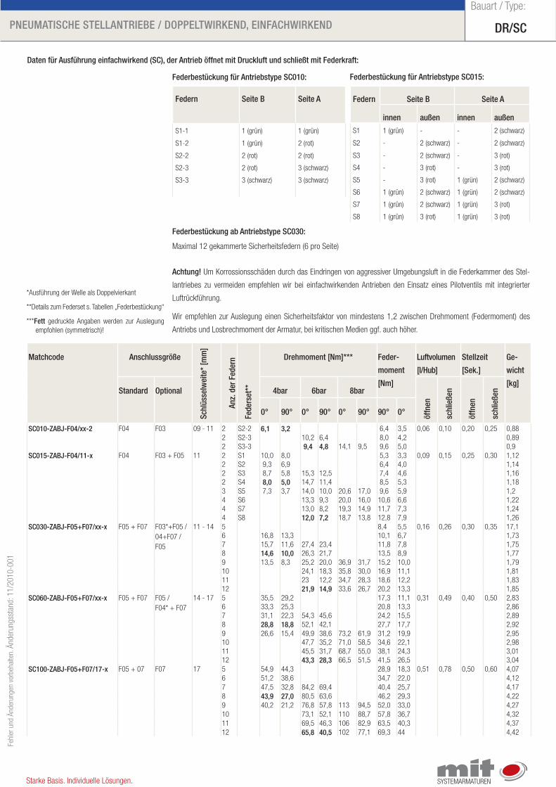
matchcode anschlussgröße
Schl
üsse
lwei
te*
[mm
]
anz.
der
fed
ern
fede
rset
**
Drehmoment [nm]*** feder-
moment
[nm]
luftvolumen
[l/hub]
Stellzeit
[Sek.]
Ge-
wicht
[kg]Standard optional 4bar 6bar 8bar
öffn
en
schl
ieße
n
öffn
en
schl
ieße
n
0° 90° 0° 90° 0° 90° 90° 0°
SC010-ZabJ-f04/xx-2 F04 F03 09 - 11 2 S2-2 6,1 3,2 6,4 3,5 0,06 0,10 0,20 0,25 0,882 S2-3 10,2 6,4 8,0 4,2 0,892 S3-3 9,4 4,8 14,1 9,5 9,6 5,0 0,9
SC015-ZabJ-f04/11-x F04 F03 + F05 11 2 S1 10,0 8,0 5,3 3,3 0,09 0,15 0,25 0,30 1,122 S2 9,3 6,9 6,4 4,0 1,142 S3 8,7 5,8 15,3 12,5 7,4 4,6 1,162 S4 8,0 5,0 14,7 11,4 8,5 5,3 1,183 S5 7,3 3,7 14,0 10,0 20,6 17,0 9,6 5,9 1,24 S6 13,3 9,3 20,0 16,0 10,6 6,6 1,224 S7 13,0 8,2 19,3 14,9 11,7 7,3 1,244 S8 12,0 7,2 18,7 13,8 12,8 7,9 1,26
SC030-ZabJ-f05+f07/xx-x F05 + F07 F03*+F05 /04+F07 / F05
11 - 14 5 8,4 5,5 0,16 0,26 0,30 0,35 17,16 16,8 13,3 10,1 6,7 1,737 15,7 11,6 27,4 23,4 11,8 7,8 1,758 14,6 10,0 26,3 21,7 13,5 8,9 1,779 13,5 8,3 25,2 20,0 36,9 31,7 15,2 10,0 1,7910 24,1 18,3 35,8 30,0 16,9 11,1 1,8111 23 12,2 34,7 28,3 18,6 12,2 1,8312 21,9 14,9 33,6 26,7 20,2 13,3 1,85
SC060-ZabJ-f05+f07/xx-x F05 + F07 F05 / F04* + F07
14 - 17 5 35,5 29,2 17,3 11,1 0,31 0,49 0,40 0,50 2,836 33,3 25,3 20,8 13,3 2,867 31,1 22,3 54,3 45,6 24,2 15,5 2,898 28,8 18,8 52,1 42,1 27,7 17,7 2,929 26,6 15,4 49,9 38,6 73,2 61,9 31,2 19,9 2,9510 47,7 35,2 71,0 58,5 34,6 22,1 2,9811 45,5 31,7 68,7 55,0 38,1 24,3 3,0112 43,3 28,3 66,5 51,5 41,5 26,5 3,04
SC100-ZabJ-f05+f07/17-x F05 + 07 F07 17 5 54,9 44,3 28,9 18,3 0,51 0,78 0,50 0,60 4,076 51,2 38,6 34,7 22,0 4,127 47,5 32,8 84,2 69,4 40,4 25,7 4,178 43,9 27,0 80,5 63,6 46,2 29,3 4,229 40,2 21,2 76,8 57,8 113 94,5 52,0 33,0 4,2710 73,1 52,1 110 88,7 57,8 36,7 4,3211 69,5 46,3 106 82,9 63,5 40,3 4,3712 65,8 40,5 102 77,1 69,3 44 4,42
Daten für ausführung einfachwirkend (SC), der antrieb öffnet mit Druckluft und schließt mit federkraft:
federn Seite b Seite a
S1-1 1 (grün) 1 (grün)
S1-2 1 (grün) 2 (rot)
S2-2 2 (rot) 2 (rot)
S2-3 2 (rot) 3 (schwarz)
S3-3 3 (schwarz) 3 (schwarz)
federbestückung für antriebstype SC010:
federn Seite b Seite a
innen außen innen außen
S1 1 (grün) - - 2 (schwarz)
S2 - 2 (schwarz) - 2 (schwarz)
S3 - 2 (schwarz) - 3 (rot)
S4 - 3 (rot) - 3 (rot)
S5 - 3 (rot) 1 (grün) 2 (schwarz)
S6 1 (grün) 2 (schwarz) 1 (grün) 2 (schwarz)
S7 1 (grün) 2 (schwarz) 1 (grün) 3 (rot)
S8 1 (grün) 3 (rot) 1 (grün) 3 (rot)
federbestückung für antriebstype SC015:
Maximal 12 gekammerte Sicherheitsfedern (6 pro Seite)
achtung! Um Korrossionsschäden durch das Eindringen von aggressiver Umgebungsluft in die Federkammer des Stel-
lantriebes zu vermeiden empfehlen wir bei einfachwirkenden Antrieben den Einsatz eines Pilotventils mit integrierter
Luftrückführung.
Wir empfehlen zur Auslegung einen Sicherheitsfaktor von mindestens 1,2 zwischen Drehmoment (Federmoment) des
Antriebs und Losbrechmoment der Armatur, bei kritischen Medien ggf. auch höher.
federbestückung ab antriebstype SC030:
*Ausführung der Welle als Doppelvierkant
**Details zum Federset s. Tabellen „Federbestückung“
***fett gedruckte Angaben werden zur Auslegung empfohlen (symmetrisch)!
DR/SCPneumatiSChe StellantRiebe / DoPPeltwiRkenD, einfaChwiRkenD
Bauart / Type:Fe
hler
und
Änd
erun
gen
vorb
ehal
ten.
Änd
erun
gsst
and:
11/
2010
-001
Starke Basis. Individuelle Lösungen.
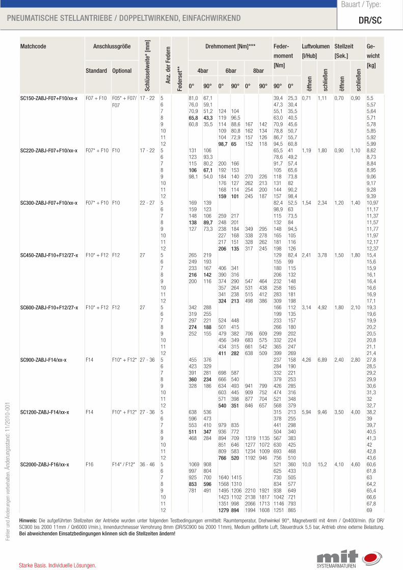
matchcode anschlussgröße
Schl
üsse
lwei
te*
[mm
]
anz.
der
fed
ern
fede
rset
**
Drehmoment [nm]*** feder-
moment
[nm]
luftvolumen
[l/hub]
Stellzeit
[Sek.]
Ge-
wicht
[kg]Standard optional 4bar 6bar 8bar
öffn
en
schl
ieße
n
öffn
en
schl
ieße
n
0° 90° 0° 90° 0° 90° 90° 0°
SC150-ZabJ-f07+f10/xx-x F07 + F10 F05* + F07/F07
17 - 22 5 81,0 67,1 39,4 25,3 0,71 1,11 0,70 0,90 5,56 76,0 59,1 47,3 30,4 5,577 70,9 51,2 124 104 55,1 35,5 5,648 65,8 43,3 119 96,5 63,0 40,5 5,719 60,8 35,5 114 88,6 167 142 70,9 45,6 5,7810 109 80,8 162 134 78,8 50,7 5,8511 104 72,9 157 126 86,7 55,7 5,9212 98,7 65 152 118 94,5 60,8 5,99
SC220-ZabJ-f07+f10/xx-x F07* + F10 F10 17 - 22 5 131 106 65,5 41 1,19 1,80 0,90 1,10 8,626 123 93,3 78,6 49,2 8,737 115 80,2 200 166 91,7 57,4 8,848 106 67,1 192 153 105 65,6 8,959 98,1 54,0 184 140 270 226 118 73,8 9,0610 176 127 262 213 131 82 9,1711 168 114 254 200 144 90,2 9,2812 159 101 245 187 157 98,4 9,39
SC300-ZabJ-f07+f10/xx-x F07* + F10 F10 22 - 27 5 169 139 82,4 52,5 1,54 2,34 1,20 1,40 10,976 159 123 98,9 63 11,177 148 106 259 217 115 73,5 11,378 138 89,7 248 201 132 84 11,579 127 73,3 238 184 349 295 148 94,5 11,7710 227 168 338 278 165 105 11,9711 217 151 328 262 181 116 12,1712 206 135 317 245 198 126 12,37
SC450-ZabJ-f10+f12/27-x F10* + F12 F12 27 5 265 219 129 82,4 2,41 3,78 1,50 1,80 15,46 249 193 155 99 15,67 233 167 406 341 180 115 15,98 216 142 390 316 206 132 16,19 200 116 374 290 547 464 232 148 16,410 357 264 531 438 258 165 16,611 341 238 515 412 283 181 16,912 324 213 498 386 309 198 17,1
SC600-ZabJ-f10+f12/27-x F10* + F12 F12 27 5 342 288 166 112 3,14 4,92 1,80 2,10 19,36 319 255 199 135 19,67 297 221 524 448 233 157 19,98 274 188 501 415 266 180 20,29 252 155 479 382 706 609 299 202 20,510 456 349 683 575 332 224 20,811 434 315 661 542 365 247 21,112 411 282 638 509 399 269 21,4
SC900-ZabJ-f14/xx-x F14 F10* + F12* 27 - 36 5 455 376 237 158 4,26 6,89 2,40 2,80 27,86 423 329 284 190 28,57 391 281 698 587 332 221 29,28 360 234 666 540 379 253 29,99 328 186 634 493 941 799 426 285 30,610 603 445 909 752 474 316 31,311 571 398 877 704 521 348 3212 540 351 846 657 568 379 32,7
SC1200-ZabJ-f14/xx-x F14 F10* + F12* 27 - 36 5 638 536 315 213 5,94 9,46 3,50 4,00 38,26 596 473 378 255 397 553 410 979 835 441 298 39,78 511 347 936 772 504 340 40,59 468 284 894 709 1319 1135 567 383 41,310 851 646 1277 1072 630 425 4211 809 583 1234 1009 693 468 42,812 766 520 1192 946 756 510 43,6
SC2000-ZabJ-f16/xx-x F16 F14* / F12* 36 - 46 5 1069 908 521 360 10,0 15,2 4,10 4,60 60,66 997 804 625 433 61,87 925 700 1640 1415 730 505 638 853 596 1568 1310 834 577 64,29 781 491 1495 1206 2210 1921 938 649 65,410 1423 1102 2138 1817 1042 721 66,611 1351 998 2066 1713 1146 793 67,812 1279 894 1994 1608 1251 865 69
hinweis: Die aufgeführten Stellzeiten der Antriebe wurden unter folgenden Testbedingungen ermittelt: Raumtemperatur, Drehwinkel 90°, Magnetventil mit 4mm / Qn400l/min. (für DR/SC900 bis 2000 11mm / Qn6000 l/min.), Innendurchmesser Verrohrung 8mm (DR/SC900 bis 2000 11mm), Medium gefilterte Luft, Steuerdruck 5,5 bar, Antrieb ohne externe Belastung. bei abweichenden einsatzbedingungen können sich die Stellzeiten ändern!
DR/SCPneumatiSChe StellantRiebe / DoPPeltwiRkenD, einfaChwiRkenD
Bauart / Type:Fe
hler
und
Änd
erun
gen
vorb
ehal
ten.
Änd
erun
gsst
and:
11/
2010
-001
Starke Basis. Individuelle Lösungen.
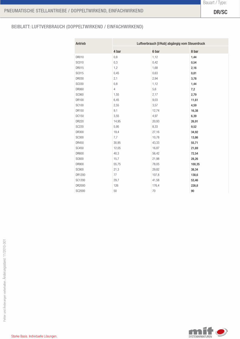
beiblatt: luftVeRbRauCh (DoPPeltwiRkenD / einfaChwiRkenD)
antrieb luftverbrauch [l/hub] abgängig vom Steuerdruck
4 bar 6 bar 8 bar
DR010 0,8 1,12 1,44
SC010 0,3 0,42 0,54
DR015 1,2 1,68 2,16
SC015 0,45 0,63 0,81
DR030 2,1 2,94 3,78
SC030 0,8 1,12 1,44
DR060 4 5,6 7,2
SC060 1,55 2,17 2,79
DR100 6,45 9,03 11,61
SC100 2,55 3,57 4,59
DR150 9,1 12,74 16,38
DC150 3,55 4,97 6,39
DR220 14,95 20,93 26,91
SC220 5,95 8,33 9,52
DR300 19,4 27,16 34,92
SC300 7,7 10,78 13,86
DR450 30,95 43,33 55,71
SC450 12,05 16,87 21,69
DR600 40,3 56,42 72,54
SC600 15,7 21,98 28,26
DR900 55,75 78,05 100,35
SC900 21,3 29,82 38,34
DR1200 77 107,8 138,6
SC1200 29,7 41,58 53,46
DR2000 126 176,4 226,8
SC2000 50 70 90
DR/SCPneumatiSChe StellantRiebe / DoPPeltwiRkenD, einfaChwiRkenD
Bauart / Type:Fe
hler
und
Änd
erun
gen
vorb
ehal
ten.
Änd
erun
gsst
and:
11/
2010
-001
Starke Basis. Individuelle Lösungen.
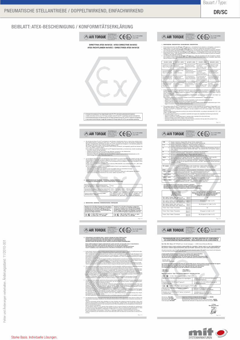
beiblatt: ateX-beSCheiniGunG / konfoRmitätSeRkläRunG
DIRETTIVA ATEX 94/9/CE / ATEX DIRECTIVE 94/9/EC
ATEX RICHTLINIEN 94/9/EC / DIRECTIVES ATEX 94/9/CE
� Istruzioni di sicurezza per l’uso degli attuatori serie AT e PT in atmosfere potenzialmente esplosive.
� Safety instructions for the use of Air Torque actuators series AT and PT in potentially explosive atmospheres.
� Sicherheitsanweisung für die Benutzung der Air Torque Antriebe der Serie AT und PT in explosiver Umgebung.
� Instructions de sécurité pour l’usage des actuateurs Air Torque séries AT et PT en atmosphères explosives.
Doc.: N° ATX- ISTR09
Issue: 12/09
AIR TORQUE S.p.A.Via Alla Campagna, 124060 Costa di MezzateBergamo - ItalyTel.:+39 035 682299Fax: +39 035 687791www.airtorque.it
Doc.: N° ATX- ISTR09
Issue: 12/09
Pag.: 2 / 6
AIR TORQUE S.p.A.Via Alla Campagna, 124060 Costa di MezzateBergamo - ItalyTel.:+39 035 682299Fax: +39 035 687791www.airtorque.it
1. DESCRIZIONE / DESCRIPTION / SCHILDERUNG / DESCRIPTION
• Gli attuatori pneumatici serie AT yyyy e PT yyyy (yyyy = size attuatore) sono attuatori a cremagliera, a semplice odoppio effetto, con case esterno in lega leggera oppure in acciaio inox, disponibili nelle seguenti versioni:
• The pneumatic actuators series AT yyyy and PT yyyy (yyyy = actuator size) are rack and pinion actuators, spring re-turn or double acting, with external housing in aluminium alloy or in stainless steel, available in the following versions:
• Die pneumatischen Antriebe der Serie AT yyyy und PT yyyy (yyyy = Antriebsgröße) sind Antriebe nach dem PrinzipKolben/Ritzel, einfach- oder doppeltwirkend, mit einem Gehäuse aus einer Aluminiumlegierung oder aus Edelstahl,verfügbar in den folgenden Versionen:
• Les actuateurs pneumatiques série AT yyyy et PT yyyy (yyyy = taille de l’actuateur) sont des actuateurs à crémail-lère et pignons, simple effet ou double effet, avec carter an alliage d’aluminium ou en acier inoxydable, disponiblesdans les versions suivantes:
• Gli attuatori serie AT e PT sono apparecchiature per l’uso in zone classificate con presenza di gas e/o polveri com-bustibili (gruppo II, categoria 2 GD, zona 1 / zona 21) oppure per l’uso in miniera (gruppo I, categoria M2). Gli attua-tori serie AT e PT, quali apparecchiature di categoria 2, sono inoltre idonei anche all’uso in zona 2 (gas) / zona 22(dust), categoria 3 GD.Essi sono progettati e costruiti in accordo alla direttiva ATEX 94/9/CE, secondo le norme EN 1127-1, EN 13463-1 edEN 13463-5.Sugli attuatori serie AT e PT é possibile montare e fornire anche separatamente, i seguenti accessori:- flangia in alluminio sul lato superiore;- adattatore in alluminio, ferro nichelato o acciaio inossidabile, inserito alle estremità del pignone;- flangia in alluminio sul lato inferiore per la connessione a valvole;- componenti meccanici quali piastrine o blocchetti in alluminio avvitati sul lato superiore dell’attuatore per il mon-
taggio di accessori (finecorsa, sensori di posizione, ecc.).
• The actuators series AT and PT are equipment for the use in zones classified with the presence of gas and/or com-bustible dusts (group II, category 2 GD, zone 1 / zone 21) or for the use in mines (group I, category M2). The actua-tors series AT and PT, as equipment of category 2, are also suitable for the use in zone 2 (gas) / zone 22 (dust),category 3 GD.They are designed and produced according to the directive ATEX 94/9/CE, according to standards EN 1127-1, EN13463-1 and EN 13463-5.On actuators series AT and PT it is possible to assemble and supply also separately the following accessories:- aluminium flange on top side;- adaptor in aluminium, nickel plated steel or stainless steel, inserted at the drive shaft ends; - aluminium flange on the bottom side for valve connection;- mechanical components such as plates or aluminium blocks screwed on the top side of the actuator for ac-
cessories assembly (limit switches, position sensors, etc.).
ST (-40°C / + 80°C)
Per applicazioni normali.(Valida solo per i modelliATyyyy U e PTyyyy B.)
For normal applications.(Valid only for models ATyyyy U and PTyyyy B.)
Für normale Anwendung.(Gültig nur für BaureiheATyyyy U und PTyyyy B.)
Pour applications normales. (Valide seulement pourmodèles ATyyyy U etPTyyyy B.)
HT (-15°C / + 150°C)
Per applicazioni ad altatemperatura. (Valida per tutti i modelli.)
For applications at hightemperature.(Valid for all models.)
Für Anwendungen beihoher Temperatur.(Gültig für alle Baureihen)
Pour applications à hautetempérature.(Valable pour tous lesmodèles.)
LLT (-55°C / + 80°C)
Per applicazioni a tempe-ratura bassa estrema. (Valida per tutti i modelli.)
For applications atextreme low temperature.(Valid for all models.)
Für Anwendungen beiextrem tiefer Temperatur.(Gültig für alle Baureihen)
Pour applications à trèsbasse température.(Valable pour tous lesmodèles.)
LT (-40°C / + 80°C)
Per applicazioni a bassatemperatura. (Non valida per i modelliATyyyy U e PTyyyy B.)
For applications at lowtemperature.(Not valid for models ATyyyy U and PTyyyy B.)
Für Anwendungen beitiefen Temperaturen.(Nicht gültig für BaureiheAtyyyy U und Ptyyyy B.)
Pour applications à bassetempérature.(Pas valide pour modèlesATyyyy U et PTyyyy B.)
STD (-20°C / + 80°C)
Per applicazioni normali.Non valida per i modelliATyyyy U e PTyyyy B.
For normal applications.(Not valid for models ATyyyy U and PTyyyy B.)
Für normale Anwendung.(Nicht gültig für BaureiheAtyyyy U und Ptyyyy B.)
Pour applicationsnormales. (Pas valide pour modèlesATyyyy U et PTyyyy B.)
Doc.: N° ATX- ISTR09
Issue: 12/09
Pag.: 3 / 6
AIR TORQUE S.p.A.Via Alla Campagna, 124060 Costa di MezzateBergamo - ItalyTel.:+39 035 682299Fax: +39 035 687791www.airtorque.it
• Die Antriebe der Serie AT und PT sind Geräte für den Einsatz in klassifizierten Zonen, in denen Gas und/oder brenn-bare Stäube (Gruppe II, Kategorie 2 GD, Zone 1 / Zone 21) vorhanden sind, oder für den Einsatz in Bergwerken(Gruppe I, Kategorie M2). Die Antriebe der Serie AT und PT, als Geräte der Kategorie 2, sind ebenfalls geeignet fürden Einsatz in der Zone 2 (Gas) / Zone 22 (Staub), Kategorie 3 GD.Sie sind in Übereinstimmung mit der Richtlinie ATEX 94/9/CE konstruiert und hergestellt, gemäß den Normen EN1127-1, EN 13463-1 und EN 13463-5.Es ist möglich an Antrieben der Baureihe AT und PT folgende Zubehörteile zu montieren bzw. einzeln anzubringen:- Aluminium Flansch auf der Oberseite;- Adapter aus Aluminium, Stahl vernickelt oder Edelstahl, eingesetzt an den Wellenenden; - Aluminium Flansch auf der Unterseite zur Anbindung an Armaturen;- Mechanische Bauteile wie Platten oder Aluminiumblöcke aufgeschraubt auf die Antriebsoberseite zur Zu-
behörmontage (Endschalter, Stellungsanzeiger etc.).
• Les actuateurs séries AT et PT sont équipement d’une utilisation en zones classifiées avec présence de gaz et/oude poussières combustibles (groupe II, catégorie 2 GD, zone 1 / zone 21) ou pour l’usage dans les mines (groupe I,catégorie M2). Les actuateurs série AT et PT, en tant qu’équipement de la catégorie 2, sont aussi utilisables en zone2 (gaz) / zone 22 (poussière), catégorie 3 GD.Ils sont conçus et produits en accordance avec la directive ATEX 94/9/CE, et aux standards EN 1127-1, EN 13463-1 et EN 13463-5.Sur les actuateurs série AT et PT il est possible d’installer et fournir aussi séparément les accessoires suivants:- bride en aluminium sur le côté supérieur;- adaptateur en aluminium, acier nickelé ou acier inoxydable inséré aux extrémités de la tige;- bride en aluminium sur le côté inférieur pour la connection sur vanne;- composants méchaniques comme platines ou blocs en aluminium vissés sur le côté supérieur de l’action-
neur pour le montage d’accessoires (fin de course, capteur de position, etc.).
2. CARATTERISTICHE TECNICHE / TECHNICAL CHARACTERISTICSTECHNISCHE EIGENSCHAFTEN / CARACTERISTIQUES TECHNIQUES
Pressione massima / Max operating pressureMax. Betriebsdruck / Pression d’utilisation maxi 10 bar
Temperatura di esercizio / Operating temperature - 55°C ¸ + 80°C (LLT); - 40°C ¸ + 80°C (LT ST);Betriebstemperatur / Température d’utilisation - 20°C ¸ + 80°C (STD); - 15°C ¸ + 150°C (HT);
Fluido di alimentazione / Operating media Aria - gas inerte - acqua - fluidi non pericolosi / Air - inert gas - water -
Betriebsmedium / Médiums non dangerous fluids / Luft - Edelgas - Wasser - ungefährlicheFlüssigkeiten / Air - gaz inerte - eau - fluides non dangereux
3. MARCATURA / MARKING / KENNZEICHNUNG / MARQUAGE
Attuatori LLT, LT, ST, STD e HT (gruppo II) in lega leggera /Actuators LLT, LT, ST, STD and HT (group II) in alluminiumalloy Antriebe LLT, LT, ST, STD und HT (Gruppe II) ausAluminiumlegierung / Actuateurs LLT, LT, ST, STD et HT(groupe II) en alliage d’aluminium.
II 2 GD c T95°C oppure / or / oder / ou T165°C (HT) T. F. : ATX 09AT
Attuatori LLT, LT, ST, STD e HT (gruppo I e gruppo II) inacciaio inox / Actuators LLT, LT, ST, STD and HT (group Iand group II) in stainless steel / Antriebe LLT, LT, ST, STDund HT Gruppe I und Gruppe II) aus Edelstahl / ActuateursLLT, LT, ST, STD et HT (groupe I et groupe II) en acier inox.
I M2 / II 2 GD c T95°C oppure / or / oder / ou T165°C (HT) T. F.: ATX 09AT
Doc.: N° ATX- ISTR09
Issue: 12/09
Pag.: 4 / 6
AIR TORQUE S.p.A.Via Alla Campagna, 124060 Costa di MezzateBergamo - ItalyTel.:+39 035 682299Fax: +39 035 687791www.airtorque.it
I M2 = Gruppo I (miniera) categoria M2 / Group I (mine) category M2 /Gruppe I (Bergwerke), Kategorie M2 / Groupe I (mines), catégorie M2
II 2 = Gruppo II (superficie), categoria 2 / Group II (surface), category 2 /Gruppe II (Oberfläche), Kategorie 2 / Groupe II (surface), catégorie 2.
G = Atmosfera esplosiva con presenza di gas, vapori o nebbie / Explosive gas atmosphere, vapours orfogs / Explosive Gasatmosphäre, Dämpfe oder Nebel / Gaz explosifs dans l’atmosphère, vapeursou brouillards.
D = Atmosfera esplosiva con presenza di polveri / Explosive dust atmosphere / Explosive Staubatmosphäre / Atmosphère de poussières explosives.
c = Sicurezza costruttiva EN 13463-5 / Design safety EN 13463-5 / Konstruktive Sicherheit EN 13463-5 / Sécurité de construction EN 13463-5.
T95°C = Temperatura massima, oppure T165°C (per HT) / Maximum temperature or T165°C (for HT) / Maximale Temperatur oder T165°C (für HT) / Température maxi 165°C ( pour HT).
T. F. = Riferimento al fascicolo tecnico depositato ATX 09AT / Reference to the registered technical fileATX 09AT / Verweis auf die registrierte Dokumentation ATX 09AT / Référence au dossier techniqueenregistré ATX 09AT.
AA / yyyyyy = Numero di serie (AA / yyyyyy =AA / progressivo) / Serial number (AA / yyyyyy = AA /progressive) / Seriennummer (AA / yyyyyy = AA / fortlaufend) / Numéros de série(AA/yyyyyy=AA/progressifs).
IP 67 = Grado di protezione / Grade of protection / Schutzklasse / Indice de protection
- 55°C ÷ + 80°C = Temperatura di esercizio (per LLT) / Operating temperature (for LLT) / Betriebstemperatur (für LLT) / Température d’utilisation (pour LLT).
- 40°C ÷ + 80°C = Temperatura di esercizio (per LT e ST) / Operating temperature (for LT and ST) / Betriebstemperatur (für LT und ST) / Température d’utilisation (pour LT et ST).
- 20°C ÷ + 80°C = Temperatura di esercizio (per STD) / Operating temperature (for STD) / Betriebstemperatur (für STD) / Température d’utilisation (pour STD).
- 15°C ÷ + 150°C = Temperatura di esercizio (per HT) / Operating temperature (for HT) / Betriebstemperatur (für HT) / Température d’utilisation (pour HT).
• Corrispondenze tra zone pericolose, sostanze e categorie Correspondences between hazardous areas, substances and categoriesBeziehungen zwischen Gefahrenbereich, Stoffen und KategorienCorrespondances entre aires dangereuses, substances et catégories.
Zona pericolosa Hazardous area Gefahrenbereich
Zones dangereuses
Gas, vapori o nebbie / Gas, vapours, etc. Zona 0 /Gas, Dämpfe oder Nebel / Gaz, vapeurs, etc. Zone 0 /
Gas, vapori o nebbie / Gas, vapours, etc. Zona 1 /Gas, Dämpfe oder Nebel / Gaz, vapeurs, etc. Zone 1 /
Gas, vapori o nebbie / Gas, vapours, etc. Zona 2 /Gas, Dämpfe oder Nebel / Gaz, vapeurs, etc. Zone 2 /
Polveri / Dust / Staub / Poussières Zona 20 /Zone 20 /
Polveri / Dust / Staub / Poussières Zona 21 /Zone 21 /
Polveri / Dust / Staub / Poussières Zona 22 /Zone 22 /
Categorie secondo Direttiva 94/9/CE Equipment category according to Directive 94/9/CE
Gerätekategorie gemäß Richtlinie 94/9/CECatégories selon Directive 94/9/CE
1G
2G oppure / or /oder / ou 1G
3G, 2G oppure / or / oder / ou 1G
1D
2D oppure / or/ oder / ou 1D
3D, 2D oppure /or /oder / ou 1D
Doc.: N° ATX- ISTR09
Issue: 12/09
Pag.: 5 / 6
AIR TORQUE S.p.A.Via Alla Campagna, 124060 Costa di MezzateBergamo - ItalyTel.:+39 035 682299Fax: +39 035 687791www.airtorque.it
4. ISTRUZIONI DI SICUREZZA PER L’ INSTALLAZIONE IN ZONA PERICOLOSA SAFETY INSTRUCTIONS FOR THE INSTALLATION IN HAZARDOUS AREASICHERHEITSANWEISUNGEN FÜR DEN EINBAU IN GEFAHRENBEREICHE INSTRUCTIONS DE SECURITE POUR L’INSTALLATION EN ZONES DANGEREUSES
Prima dell’installazione leggere attentamente quanto riportato nel manuale d’uso e manutenzione. Before the installation read carefully the instructions for use and maintenance. Die Anweisungen für den Betrieb und die Wartung vor der Montage sorgfältig durchlesen.Avant l’installation, lisez attentivement les instructions d’utilisation et de maintenance.
• Sugli attuatori devono essere installati apparecchiature e/o componenti elettrici (oggetto di certificazione sepa-rata secondo la direttiva ATEX) e componenti meccanici conformi alla suddetta direttiva. Tutti i componenti devono essere idonei per l’utilizzo in zone classificate con presenza di gas del gruppo II e/ocon presenza di polveri combustibili oppure per miniera (gruppo I, categoria M2). Le classi di temperatura e/o latemperatura massima dei componenti devono essere compatibili con i limiti di temperatura previsti per le diffe-renti versioni degli attuatori. Gli attuatori serie AT e PT devono essere installati e manutenzionati in accordo con le norme impiantistiche e dimanutenzione per ambienti classificati contro il rischio di esplosione per presenza di gas / polveri oppure miniera(esempio: EN 60079-14, EN 60079-17, EN 61241-14 oppure altre norme/standard nazionali). Nel caso di polveri combustibili, si deve provvedere ad una regolare pulizia per limitare la formazione di strati.Tutte le operazioni di manutenzione devono essere eseguite secondo quanto riportato nel manuale di istruzione.
• The equipment and/or electrical components (which must be separately certified according to ATEX directive) andmechanical components installed on the actuators must be according to the above directive.All the components must be suitable for the use in areas classified with presence of gas of group II and/or with pres-ence of combustible dust or for mine (group I, category M2). The classes of temperature and/or the maximum tem-perature of the components must be compatible with the temperature limits of the different actuator versions.The actuators series AT and PT must be installed and serviced according to the plant maintenance standards forareas classified against the risk of explosion for the presence of gas / dust or mine (example: EN 60079-14, EN60079-17, EN 61241-14 or other national norms/standards).In case of combustible dust, a regular cleaning must be made in order to limit the formation of layers.All the maintenance operations must be made according to what is written in the instruction manual.
• Die Betriebsmittel und/oder elektrischen Komponenten (welche gemäß der ATEX Richtlinie gesondert klassifiziertwerden müssen) und mechanischen Komponenten, die am Antrieb montiert werden, müssen in Übereinstim-mung mit der oben genannten Richtlinie stehen.Alle Komponenten müssen für den Einsatz in Bereiche geeignet sein, die für das Vorhandensein von Gas nachGruppe II und/oder für das Vorhandensein von brennbarem Staub oder für Bergwerke (Gruppe I, Kategorie M2)klassifiziert sind. Die Temperaturklassen und/oder die Maximaltemperatur der Komponenten müssen mit denTemperaturgrenzen der unterschiedlichen Antriebsversionen übereinstimmen.Die Antriebe der Serie AT und PT müssen gemäß den in Werksnormen angegebenen Bereichen, klassifiziert gegendie Explosionsgefahr bei Vorhandensein von Gas / Staub oder in Bergwerken (Beispiel: EN 60079-14, EN 60079-17, EN 61241-14 oder andere nationale Richtlinien/Normen), eingebaut werden.Bei Vorhandensein von brennbaren Stäuben muss eine regelmäßige Reinigung, zur Vermeidung einer Staub-schichtbildung, durchgeführt werden.Alle Wartungsarbeiten müssen entsprechend dem in der Bedienungsanleitung Beschriebenen durchgeführt werden.
• Les équipements et/ou composants électriques (qui doivent être certifiés séparément selon directive ATEX) et lescomposants mécaniques installés sur les actuateurs doivent être en accordance avec la directive mentionnée ci-dessus.Tous les composants doivent être utilisables en zones classées avec présence de gaz de groupe II et/ou avecprésence de poussières combustibles ou dans les mines (groupe I, catégorie M2). Les classes de températureset/ou les températures maximum des composants doivent être compatibles avec les températures limites des dif-férents versions d’actuateurs.Les actuateurs séries AT et PT doivent être installés et mis en service d’après les standards de maintenanced’usine pour les zones classifiées contre les risques d’explosion dûs à la presence de gaz/poussières ou dansles mines (exemple: EN 60079-14, EN 60079-17, EN 61241-14 ou autres norms/standards nationaux).En cas de poussières combustibles, il faut faire un nettoyage régulier pour limiter la formation de couches.Toutes les opérations de maintenance doivent être effectuées selon les directives inscrites dans le manuel d’ins-truction.
Doc.: N° ATX- ISTR09
Issue: 12/09
Pag.: 6 / 6
AIR TORQUE S.p.A.Via Alla Campagna, 124060 Costa di MezzateBergamo - ItalyTel.:+39 035 682299Fax: +39 035 687791www.airtorque.it
DICHIARAZIONE CE DI CONFORMITÀ / CE DECLARATION OF CONFORMITYCE KONFORMITAETSERKLAERUNG / DECLARATION CE DE CONFORMITÉ
Noi / We / Wir / Nous: AIR TORQUE S.p.A. Via alla Campagna, 1 - 24060 Costa di Mezzate (BG) Italy
Dichiariamo sotto la nostra esclusiva responsabilità che il prodotto / declare under our sole responsibility thatthe product / erklären eigenverantwortlich, dass das Produkt / déclarons sous notre seule responsabilité que:
Attuatori pneumatici serie AT e PT / AT and PT pneumatic actuators series / AT und PT pneumatische Antriebsserie/ Les actionneurs pneumatiques séries AT et PT
ai quali questa dichiarazione si riferisce sono conformi alle seguenti direttive:to which this declaration relates complies with the following directives:auf das sich diese Erklärung bezieht, die Forderungen der folgenden Richtlinien erfüllt:concernés par la présente déclaration sont en conformité avec les directives suivantes:
- 94/9/EC (ATEX)- 2004/42/EC (Machinery)
La conformità è stata verificata sulla base dei requisiti delle norme o dei documenti normativi riportati nel seguito:The conformity are under observance of the following standards or standards documents:Die Konformität steht unter Beachtung der folgenden Normen oder Dokumente:La conformité est vérifiée sur la base des standards et documents suivants:
� EN 1127-1 � EN 13463-5 � EN 13463-1 � prEN 15714-3
Modo di protezione / Type of protection / Schutzart / Type de protection:
� II 2 GD c T95°C oppure/or/oder/ou T165°C (HT)
Attuatori LLT, LT, ST, STD e HT (gruppo II) in lega leggera. Antriebe LLT, LT, ST, STD und HT (Gruppe II)aus Aluminiumlegierung.
Actuators LLT, LT, ST, STD and HT (group II) Actuateurs LLT, LT, ST, STD et HT (groupe II) in alluminium alloy. en alliage d’aluminium.
� I M2/II 2 GD c T95°C oppure/or/oder/ou T165°C (HT)
Attuatori LLT, LT, ST, STD e HT (gruppo I e gruppo II) Antriebe LLT, LT, ST, STD und HTin acciaio inox. (Gruppe I und Gruppe II) aus Edelstahl.
Actuators LLT, LT, ST, STD and HT (group I and group II) Actuateurs LLT, LT, ST, STD et HT in stainless steel. (groupe I et groupe II) en acier inox.
File tecnico: ATX 09AT Organismo Notificato di deposito del fascicolo tecnico: INERISTechnical file: ATX 09AT Notified Body of deposit of technical file: INERISTechnische Daten: ATX 09AT Hinterlegung der Dokumentation bei einer „Benannten Stelle“: INERISFiche tecnique: ATX 09AT Organisme de notification et dépositaire des fiches techniques: INERIS
S. RotaManaging Director
Signature