Bedienungsanleitung de Instruction manual en - media.testo.com · air system to ensure long-lasting...
20
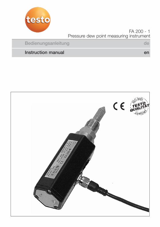
Bedienungsanleitung de FA 200 - 1 Drucktaupunkt-Messgerät Pressure dew point measuring instrument Instruction manual en
-
Upload
truongtruc -
Category
Documents
-
view
214 -
download
0
Transcript of Bedienungsanleitung de Instruction manual en - media.testo.com · air system to ensure long-lasting...
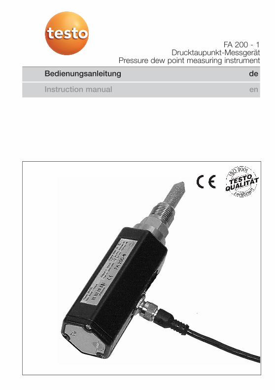
Bedienungsanleitung de
FA 200 - 1Drucktaupunkt-Messgerät
Pressure dew point measuring instrument
Instruction manual en
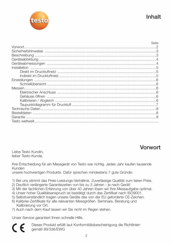
Liebe Testo Kundin,lieber Testo-Kunde,
Ihre Entscheidung für ein Messgerät von Testo war richtig. Jedes Jahr kaufen tausendeKundenunsere hochwertigen Produkte. Dafür sprechen mindestens 7 gute Gründe:
1) Bei uns stimmt das Preis-Leistungs-Verhältnis. Zuverlässige Qualität zum fairen Preis.2) Deutlich verlängerte Garantiezeiten von bis zu 3 Jahren - je nach Gerät!3) Mit der fachlichen Erfahrung von über 40 Jahren lösen wir Ihre Messaufgabe optimal.4) Unser hoher Qualitätsanspruch ist bestätigt durch das Zertifikat nach ISO9001.5) Selbstverständlich tragen unsere Geräte das von der EU geforderte CE-Zeichen. 6) Kalibrier-Zertifikate für alle relevanten Messgrößen. Seminare, Beratung und
Kalibrierung vor Ort. 7) Auch nach dem Kauf lassen wir Sie nicht im Regen stehen.
Unser Service garantiert Ihnen schnelle Hilfe.
SeiteVorwort................................................................................................................................2Sicherheitshinweise ............................................................................................................3Beschreibung ......................................................................................................................3Geräteabbildung ..................................................................................................................4Geräteabmessungen ..........................................................................................................4Installation ..........................................................................................................................5
Direkt im Druckluftnetz ................................................................................................5Indirekt im Druckluftnetz ..............................................................................................5
Einstellungen ......................................................................................................................6Schnellübersicht ..........................................................................................................6
Messen................................................................................................................................6Elektrischer Anschluss ................................................................................................6Gehäuse öffnen ..........................................................................................................6Kalibrieren / Abgleich ..................................................................................................6Taupunktdiagramm für Druckluft ..................................................................................7
Technische Daten ................................................................................................................8Bestelldaten ........................................................................................................................8Garantie ..............................................................................................................................9Testo weltweit........................................................................................................................
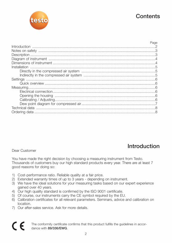
Inhalt
Vorwort
2
Dieses Produkt erfüllt laut Konformitätsbescheinigung die Richtliniengemäß 89/336/EWG
Vor Inbetriebnahme lesen!
Druckbereich >50 bar nicht überschreiten.
Messbereiche das Messwertaufnehmers beachten!Bei Überhitzung werden die Fühler zerstört.
Zulässige Lager- und Transporttemperatur sowie diezulässige Betriebstemperatur beachten
(z. B. Messgerät vor direkter Sonneneinstrahlung schützen).
Bei Öffnen des Geräts, unsachgemäßer Behandlungoder Gewaltanwendung erlöschen die Gewährleistungsansprüche!
Einstell- und Kalibrierarbeiten nur durch qualifiziertesPersonal aus der Mess- und Regeltechnik durchführen lassen.
Bei transienten Störgrößen (Elektrostatische Entladung sowie Burst-impulse) kann es zu einem Reset des Messsystems kommen.
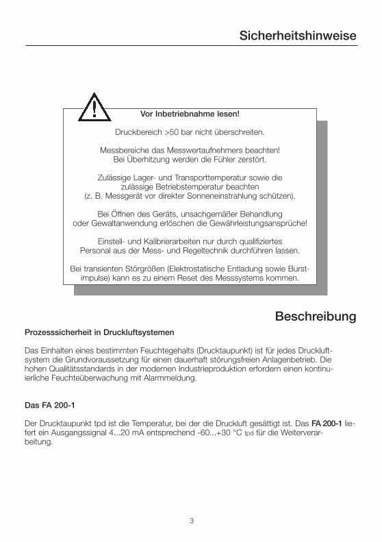
Sicherheitshinweise
Beschreibung
3
Prozesssicherheit in Druckluftsystemen
Das Einhalten eines bestimmten Feuchtegehalts (Drucktaupunkt) ist für jedes Druckluft-system die Grundvoraussetzung für einen dauerhaft störungsfreien Anlagenbetrieb. Diehohen Qualitätsstandards in der modernen Industrieproduktion erfordern einen kontinu-ierliche Feuchteüberwachung mit Alarmmeldung.
Das FA 200-1
Der Drucktaupunkt tpd ist die Temperatur, bei der die Druckluft gesättigt ist. Das FA 200-1 lie-fert ein Ausgangssignal 4...20 mA entsprechend -60...+30 °C tpd für die Weiterverar-beitung.
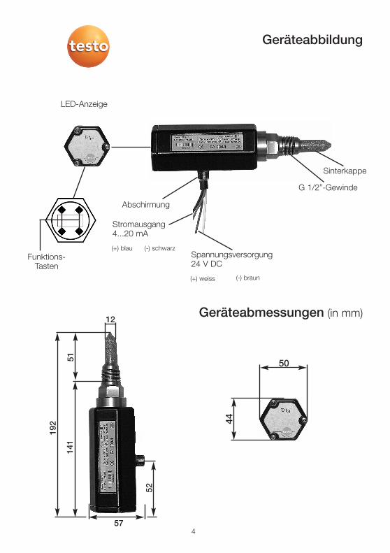
Geräteabbildung
Geräteabmessungen (in mm)
4
Sinterkappe
Spannungsversorgung24 V DC
(+) weiss (-) braun
Stromausgang4...20 mA
Abschirmung
(+) blau (-) schwarz
LED-Anzeige
Funktions-Tasten
G 1/2”-Gewinde
50
44
192
141
12
52
57
51
5
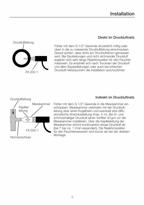
Installation
Direkt im Druckluftnetz
Indirekt im Druckluftnetz
Fühler mit dem G 1/2”-Gewinde druckdicht mittig oder oben in die zu messende Druckluftleitung einschrauben.Darauf achten, dass dicht am Druckluftstrom gemessenwird. Bei Sackleitungen und nicht strömender Druckluftergeben sich sehr lange Reaktionszeiten für den Feuchte-messwert. Es emphielt sich nach Trocknen der Druckluftund allen Bypassleitungen oder auch bei kritischenDruckluft-Verbrauchern die Installation durchzuführen
Fühler mit dem G 1/2”-Gewinde in die Messkammer ein-schrauben. Messkammer verbinden mit der Druckluft-leitung über einen Kugelhahn und eventuell eine diffu-sionsdichte Anschlussleitung (max. 5 m). Bei öl- und schmutzhaltiger Druckluft einen Vorfilter 40 µm vor derMesskammer installieren. Über die Kapillarleitung derMesskammer strömt kontinuierlich etwas Druckluft ab(bei 7 bar ca. 1 l/min expandiert). Die Reaktionszeiten für den Feuchtemesswert sind kürzer als bei der direktenMontage.
Druckluftleitung
Druckluftleitung
FA 200-1
MesskammerKapillar-leitung
Normanschluss
FA 200-1
6
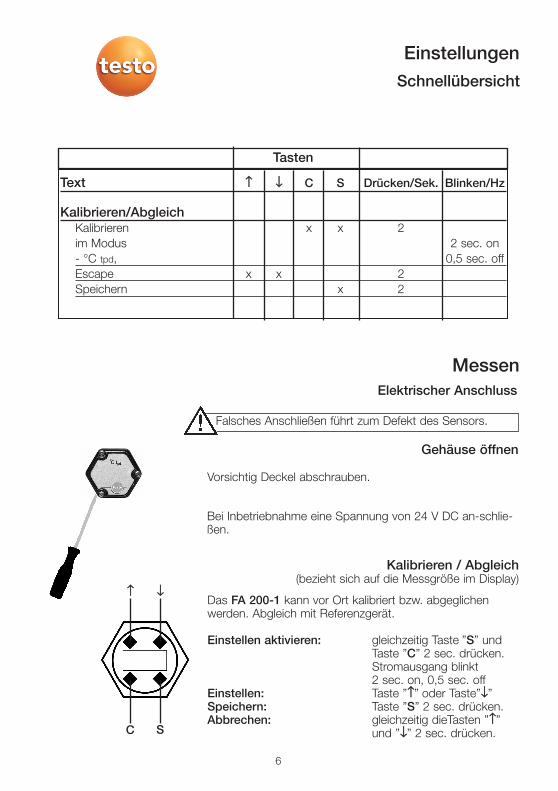
Falsches Anschließen führt zum Defekt des Sensors.
Vorsichtig Deckel abschrauben.
Bei Inbetriebnahme eine Spannung von 24 V DC an-schlie-ßen.
Gehäuse öffnen
Elektrischer Anschluss
Messen
Kalibrieren / Abgleich(bezieht sich auf die Messgröße im Display)
Das FA 200-1 kann vor Ort kalibriert bzw. abgeglichenwerden. Abgleich mit Referenzgerät.
Einstellen aktivieren: gleichzeitig Taste ”S” undTaste ”C” 2 sec. drücken.Stromausgang blinkt 2 sec. on, 0,5 sec. off
Einstellen: Taste ”↑↑” oder Taste”↓↓” Speichern: Taste ”S” 2 sec. drücken.Abbrechen: gleichzeitig dieTasten ”↑↑”
und ”↓↓” 2 sec. drücken.C
↑↑ ↓↓
S
EinstellungenSchnellübersicht
Text ↑↑ ↓↓ C S Drücken/Sek. Blinken/Hz
Kalibrieren/AbgleichKalibrieren x x 2im Modus 2 sec. on- °C tpd, 0,5 sec. offEscape x x 2Speichern x 2
Tasten
7
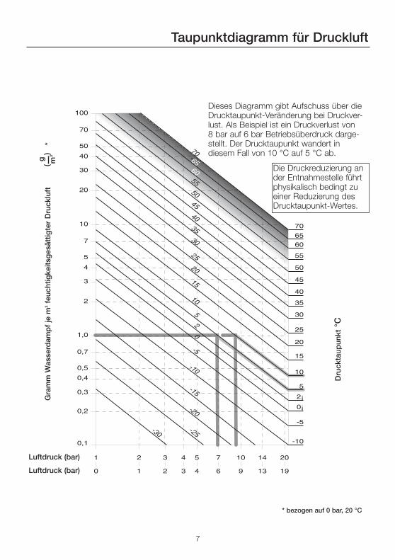
Taupunktdiagramm für Druckluft
Dieses Diagramm gibt Aufschuss über dieDrucktaupunkt-Veränderung bei Druckver-lust. Als Beispiel ist ein Druckverlust von8 bar auf 6 bar Betriebsüberdruck darge-stellt. Der Drucktaupunkt wandert in diesem Fall von 10 °C auf 5 °C ab.
Die Druckreduzierung ander Entnahmestelle führtphysikalisch bedingt zueiner Reduzierung desDrucktaupunkt-Wertes.
Dru
ckta
upun
kt°C
Gra
mm
Was
serd
amp
f je
m3
feuc
htig
keits
ges
ättig
ter
Dru
cklu
ft*
g(
)m
3
Luftdruck (bar)
Luftdruck (bar)
* bezogen auf 0 bar, 20 °C
8
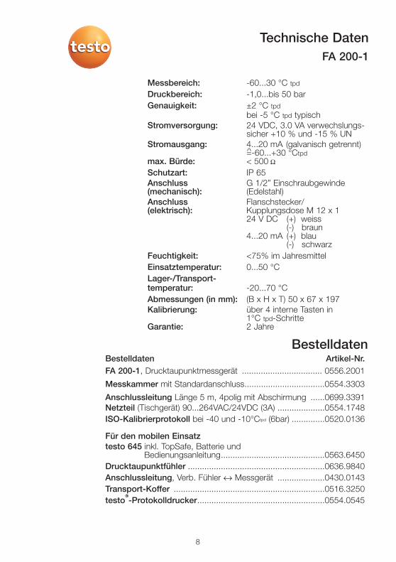
Messbereich: -60...30 °C tpd
Druckbereich: -1,0...bis 50 barGenauigkeit: ±2 °C tpd
bei -5 °C tpd typischStromversorgung: 24 VDC, 3.0 VA verwechslungs-
sicher +10 % und -15 % UNStromausgang: 4...20 mA (galvanisch getrennt)
=-60...+30 °Ctpd max. Bürde: < 500 Ω
Schutzart: IP 65Anschluss G 1/2” Einschraubgewinde(mechanisch): (Edelstahl)Anschluss Flanschstecker/(elektrisch): Kupplungsdose M 12 x 1
24 V DC (+) weiss(-) braun
4...20 mA (+) blau(-) schwarz
Feuchtigkeit: <75% im JahresmittelEinsatztemperatur: 0...50 °CLager-/Transport-temperatur: -20...70 °CAbmessungen (in mm): (B x H x T) 50 x 67 x 197Kalibrierung: über 4 interne Tasten in
1°C tpd-Schritte Garantie: 2 Jahre
Technische DatenFA 200-1
BestelldatenBestelldaten Artikel-Nr.FA 200-1, Drucktaupunktmessgerät .................................. 0556.2001
Messkammer mit Standardanschluss..................................0554.3303
Anschlussleitung Länge 5 m, 4polig mit Abschirmung ......0699.3391Netzteil (Tischgerät) 90...264VAC/24VDC (3A) ....................0554.1748ISO-Kalibrierprotokoll bei -40 und -10°Ctpd (6bar) ..............0520.0136
Für den mobilen Einsatztesto 645 inkl. TopSafe, Batterie und
Bedienungsanleitung............................................0563.6450Drucktaupunktfühler ..........................................................0636.9840Anschlussleitung, Verb. Fühler ↔ Messgerät ....................0430.0143Transport-Koffer ................................................................0516.3250 testo
®®-Protokolldrucker......................................................0554.0545


Bedienungsanleitung de
FA 200 - 1Pressure dew point measuring instrument
Instruction manual en
Dear Customer
You have made the right decision by choosing a measuring instrument from Testo.Thousands of customers buy our high standard products every year. There are at least 7good reasons for doing so:
1) Cost-performance ratio. Reliable quality at a fair price.2) Extended warranty times of up to 3 years - depending on instrument.3) We have the ideal solutions for your measuring tasks based on our expert experience
gained over 40 years.4) Our high quality standard is confirmed by the ISO 9001 certificate.5) Of course, our instruments carry the CE symbol required by the EU.6) Calibration certificates for all relevant parameters. Seminars, advice and calibration on
location.7) Our after-sales service. Ask for more details.
PageIntroduction ........................................................................................................................2Notes on safety ..................................................................................................................3Description ..........................................................................................................................3Diagram of instrument ........................................................................................................4Dimensions of instrument ....................................................................................................4Installation ..........................................................................................................................5
Directly in the compressed air system ........................................................................5Indirectly in the compressed air system ......................................................................5
Settings ..............................................................................................................................6Quick overview ............................................................................................................6
Measuring............................................................................................................................6Electrical connection....................................................................................................6Opening the housing ..................................................................................................6Calibrating / Adjusting..................................................................................................6Dew point diagram for compressed air ........................................................................7
Technical data ....................................................................................................................8Ordering data ......................................................................................................................8
Contents
Introduction
2
The conformity certificate confirms that this product fulfills the guidelines in accor-dance with 89/336/EWG.
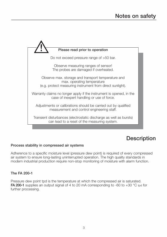
Please read prior to operation
Do not exceed pressure range of >50 bar.
Observe measuring ranges of sensor!The probes are damaged if overheated.
Observe max. storage and transport temperature andmax. operating temperature
(e.g. protect measuring instrument from direct sunlight).
Warranty claims no longer apply if the instrument is opened, in thecase of inexpert handling or use of force.
Adjustments or calibrations should be carried out by qualifiedmeasurement and control engineering staff.
Transient disturbances (electrostatic discharge as well as bursts)can lead to a reset of the measuring system.
Notes on safety
Description
3
Process stability in compressed air systems
Adherence to a specific moisture level (pressure dew point) is required of every compressedair system to ensure long-lasting uninterrupted operation. The high quality standards inmodern industrial production require non-stop monitoring of moisture with alarm function.
The FA 200-1
Pressure dew point tpd is the temperature at which the compressed air is saturated. FA 200-1 supplies an output signal of 4 to 20 mA corresponding to -60 to +30 °C tpd forfurther processing.
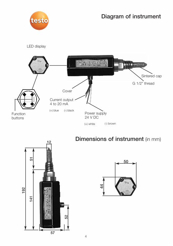
Diagram of instrument
Dimensions of instrument (in mm)
4
Sintered cap
Power supply24 V DC
(+) white (-) brown
Current output4 to 20 mA
Cover
(+) blue (-) black
LED display
Functionbuttons
G 1/2” thread
50
44
192
141
12
52
57
51
5
Installation
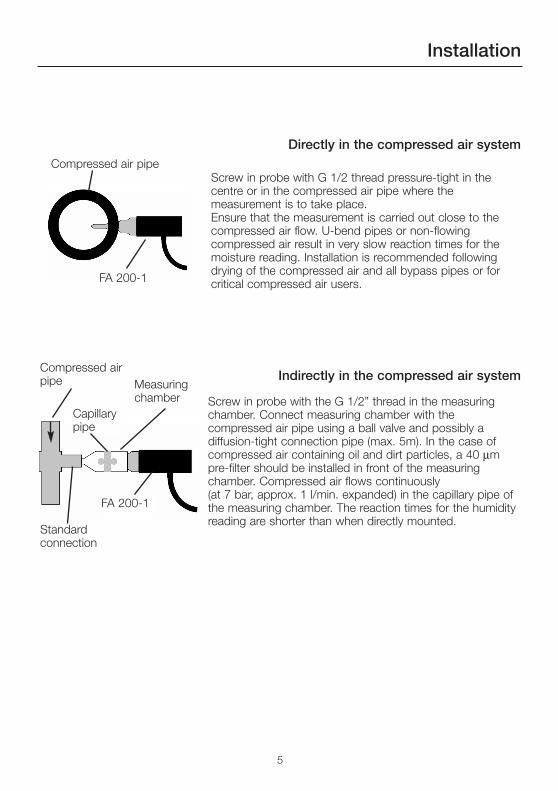
Directly in the compressed air system
Indirectly in the compressed air system
Screw in probe with G 1/2 thread pressure-tight in thecentre or in the compressed air pipe where themeasurement is to take place. Ensure that the measurement is carried out close to thecompressed air flow. U-bend pipes or non-flowingcompressed air result in very slow reaction times for themoisture reading. Installation is recommended followingdrying of the compressed air and all bypass pipes or forcritical compressed air users.
Screw in probe with the G 1/2” thread in the measuringchamber. Connect measuring chamber with thecompressed air pipe using a ball valve and possibly adiffusion-tight connection pipe (max. 5m). In the case ofcompressed air containing oil and dirt particles, a 40 µmpre-filter should be installed in front of the measuringchamber. Compressed air flows continuously (at 7 bar, approx. 1 l/min. expanded) in the capillary pipe ofthe measuring chamber. The reaction times for the humidityreading are shorter than when directly mounted.
Compressed air pipe
Compressed airpipe
FA 200-1
Measuringchamber
Capillarypipe
Standard connection
FA 200-1
6
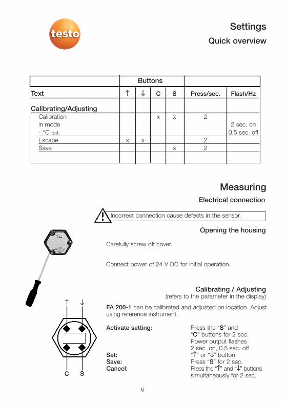
Incorrect connection cause defects in the sensor.
Carefully screw off cover.
Connect power of 24 V DC for initial operation.
Opening the housing
Electrical connection
Measuring
Calibrating / Adjusting(refers to the parameter in the display)
FA 200-1 can be calibrated and adjusted on location. Adjustusing reference instrument.
Activate setting: Press the “S” and“C” buttons for 2 sec. Power output flashes 2 sec. on, 0.5 sec. off
Set: “↑↑” or “↓↓” button Save: Press “S” for 2 sec.Cancel: Press the “↑↑” and “↓↓” buttons
simultaneously for 2 sec.C
↑↑ ↓↓
S
SettingsQuick overview
Text ↑↑ ↓↓ C S Press/sec. Flash/Hz
Calibrating/AdjustingCalibration x x 2in mode 2 sec. on- °C tpd, 0.5 sec. offEscape x x 2Save x 2
Buttons
7
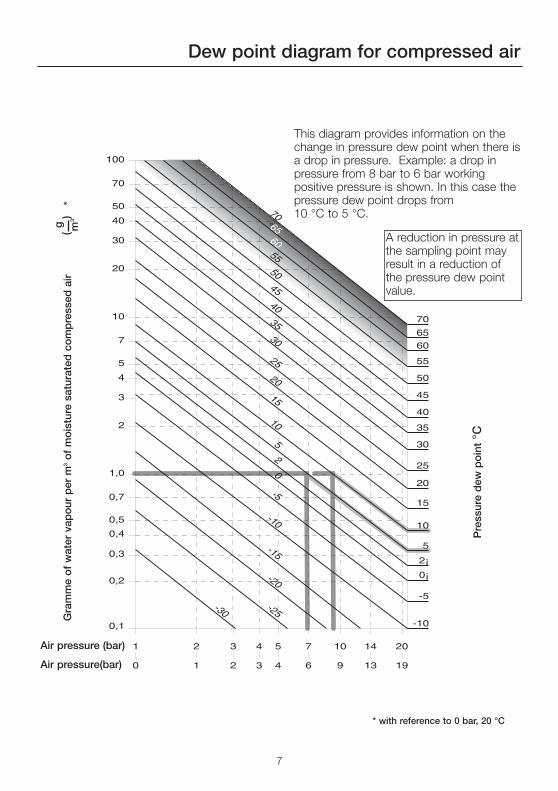
Dew point diagram for compressed air
This diagram provides information on thechange in pressure dew point when there isa drop in pressure. Example: a drop inpressure from 8 bar to 6 bar workingpositive pressure is shown. In this case thepressure dew point drops from 10 °C to 5 °C.
A reduction in pressure atthe sampling point mayresult in a reduction ofthe pressure dew pointvalue.
Pre
ssur
e d
ew p
oin
t°C
Gra
mm
e o
f w
ater
vap
our
per
m3
of
mo
istu
re s
atur
ated
co
mp
ress
ed a
ir*
g(
)m
3
Air pressure (bar)
Air pressure(bar)
* with reference to 0 bar, 20 °C
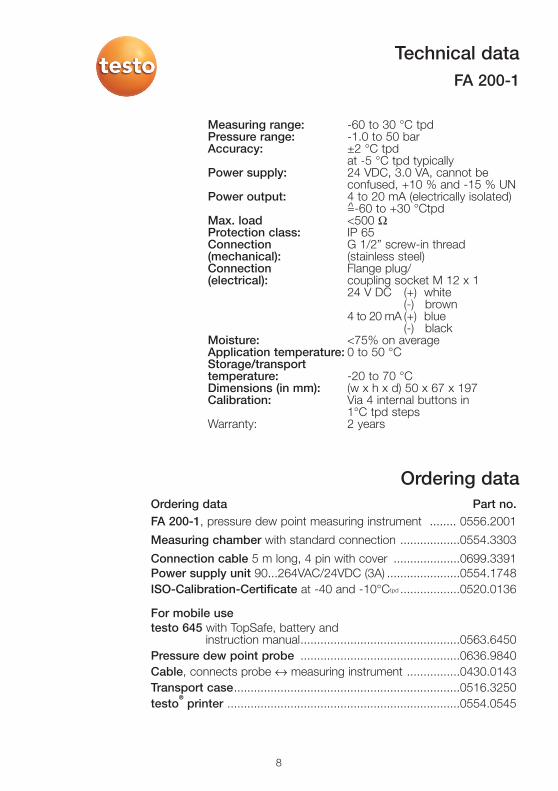
Ordering data Part no.FA 200-1, pressure dew point measuring instrument ........ 0556.2001
Measuring chamber with standard connection ..................0554.3303
Connection cable 5 m long, 4 pin with cover ....................0699.3391Power supply unit 90...264VAC/24VDC (3A) ......................0554.1748ISO-Calibration-Certificate at -40 and -10°Ctpd ..................0520.0136
For mobile usetesto 645 with TopSafe, battery and
instruction manual................................................0563.6450Pressure dew point probe ................................................0636.9840Cable, connects probe ↔ measuring instrument ................0430.0143Transport case....................................................................0516.3250 testo
®®printer ......................................................................0554.0545
8
Measuring range: -60 to 30 °C tpdPressure range: -1.0 to 50 barAccuracy: ±2 °C tpd
at -5 °C tpd typicallyPower supply: 24 VDC, 3.0 VA, cannot be
confused, +10 % and -15 % UNPower output: 4 to 20 mA (electrically isolated)
=-60 to +30 °Ctpd Max. load <500 ΩProtection class: IP 65Connection G 1/2” screw-in thread(mechanical): (stainless steel)Connection Flange plug/(electrical): coupling socket M 12 x 1
24 V DC (+) white(-) brown
4 to 20 mA (+) blue(-) black
Moisture: <75% on averageApplication temperature: 0 to 50 °CStorage/transporttemperature: -20 to 70 °CDimensions (in mm): (w x h x d) 50 x 67 x 197Calibration: Via 4 internal buttons in
1°C tpd steps Warranty: 2 years
Technical dataFA 200-1
Ordering data


testo AG
Postfach 11 40, 79849 LenzkirchTesto-Straße 1, 79853 Lenzkirch
Telefon: (07653) 681-0Fax: (07653) 681-100
E-Mail: [email protected]: http://www.testo.com
0973.5001/01/T/wh/19.03.2004