Bedienungsanleitung Instruction Manual Transmitter pH 2100 PA · PROFIBUS technology E-5 English 3...
78
Transmitter pH 2100 PA Bedienungsanleitung Instruction Manual Notice d‘utilisation
Transcript of Bedienungsanleitung Instruction Manual Transmitter pH 2100 PA · PROFIBUS technology E-5 English 3...
Deutsch
Transmitter pH 2100 PA
Bedienungsanleitung
Instruction Manual
Notice d‘utilisation

Mettler-T
oledo GmbH Process Analytics Im Hackacker 15, P.O. Box CH-8902 Urdorf Switzerland Phone: +41-1-736 22 11 Fax: +41-1-736 26 36 www.mtpro.com
Gewährleistung
Innerhalb von 1Jahr ab Lieferung auftretende Mängel werden bei
freier Anlieferung im Werk kostenlos behoben.
Softwareversion: 2.xStand Bedienungsanleitung: 24.06.2005
Warranty
Defects occurring within 1 year from delivery date shall be remedied
free of charge at our plant (carriage and insurance paid by sender).
Software release: 2.xDate of issue: June 24, 2005
Garantie
Tout défaut constaté dans les 1 an à dater de la livraison sera réparé
gratuitement dans notre usine à réception franco de l‘appareil.
Version logiciel : 2.xVersion du mode d‘emploi : 24.06.2005
TA-194.170-MTX02

Contents
E-
1
Contents
Engl
ish
1
Information on this instruction manual
. . . . . . . . . . . . . . E-3
Markings
. . . . . . . . . . . . . . . . . . . . . . . . . . . . . . . . . . . . . E-3
2
Safety information
. . . . . . . . . . . . . . . . . . . . . . . . . . . . . . . E-4
Be sure to read and observe the following instructions!
. E-4
3
PROFIBUS technology
. . . . . . . . . . . . . . . . . . . . . . . . . . . E-5
General
. . . . . . . . . . . . . . . . . . . . . . . . . . . . . . . . . . . . . E-5
Variants and basic characteristics . . . . . . . . . . . . . . . . . E-5
Definitions for PROFIBUS-PA . . . . . . . . . . . . . . . . . . . . E-5
PROFIBUS-PA with the Transmitter pH 2100 PA. . . . . E-6
4
Description
. . . . . . . . . . . . . . . . . . . . . . . . . . . . . . . . . . . . . E-7
Proper use
. . . . . . . . . . . . . . . . . . . . . . . . . . . . . . . . . . . E-7
Technical features . . . . . . . . . . . . . . . . . . . . . . . . . . . . . E-7
Communication model . . . . . . . . . . . . . . . . . . . . . . . . . . E-8
Profile for process control devices (extract) . . . . . . . . . . E-9
5
Assembly
. . . . . . . . . . . . . . . . . . . . . . . . . . . . . . . . . . . . . E-11
Package contents and unpacking
. . . . . . . . . . . . . . . . E-11
Mounting plan. . . . . . . . . . . . . . . . . . . . . . . . . . . . . . . . E-12
6
Installation and connection
. . . . . . . . . . . . . . . . . . . . . . E-15
Information on installation
. . . . . . . . . . . . . . . . . . . . . . E-15
Terminal assignments . . . . . . . . . . . . . . . . . . . . . . . . . E-17
Overview of the Transmitter pH 2100 PA. . . . . . . . . . . E-17
pH measurement . . . . . . . . . . . . . . . . . . . . . . . . . . . . . E-18
ORP measurement . . . . . . . . . . . . . . . . . . . . . . . . . . . .E-22
7
Commissioning
. . . . . . . . . . . . . . . . . . . . . . . . . . . . . . . .E-23
Checklist
. . . . . . . . . . . . . . . . . . . . . . . . . . . . . . . . . . . .E-23
8
Operation
. . . . . . . . . . . . . . . . . . . . . . . . . . . . . . . . . . . . .E-24
Operation possibilities
. . . . . . . . . . . . . . . . . . . . . . . . . .E-24
Operation using keypad on the Transmitter . . . . . . . . .E-25
Mode code . . . . . . . . . . . . . . . . . . . . . . . . . . . . . . . . . .E-27
Safety functions . . . . . . . . . . . . . . . . . . . . . . . . . . . . . .E-27
Mode indicators. . . . . . . . . . . . . . . . . . . . . . . . . . . . . . .E-28
Configuration . . . . . . . . . . . . . . . . . . . . . . . . . . . . . . . . E-29
Calibration. . . . . . . . . . . . . . . . . . . . . . . . . . . . . . . . . . .E-32
Operating tool . . . . . . . . . . . . . . . . . . . . . . . . . . . . . . . .E-40
Measurement . . . . . . . . . . . . . . . . . . . . . . . . . . . . . . . .E-40
9
Diagnostics
. . . . . . . . . . . . . . . . . . . . . . . . . . . . . . . . . . . .E-42
Sensocheck, Sensoface
. . . . . . . . . . . . . . . . . . . . . . . .E-42
PROFIBUS-PA limit monitoring . . . . . . . . . . . . . . . . . .E-43
Error messages . . . . . . . . . . . . . . . . . . . . . . . . . . . . . . E-44
Display messages and PROFIBUS communication . . .E-48
Diagnostics functions . . . . . . . . . . . . . . . . . . . . . . . . . .E-51
10
Maintenance and cleaning
. . . . . . . . . . . . . . . . . . . . . . .E-53
Maintenance
. . . . . . . . . . . . . . . . . . . . . . . . . . . . . . . . .E-53
Cleaning . . . . . . . . . . . . . . . . . . . . . . . . . . . . . . . . . . . .E-53

E-2
11 Appendix. . . . . . . . . . . . . . . . . . . . . . . . . . . . . . . . . . . . . .E-55
Product line . . . . . . . . . . . . . . . . . . . . . . . . . . . . . . . . . .E-55
Specifications . . . . . . . . . . . . . . . . . . . . . . . . . . . . . . . .E-55
ATEX EC-Type-Examination Certificate . . . . . . . . . . . .E-60
Declaration of Conformity . . . . . . . . . . . . . . . . . . . . . . .E-64
FM Control Drawing . . . . . . . . . . . . . . . . . . . . . . . . . . .E-65
Buffer tables . . . . . . . . . . . . . . . . . . . . . . . . . . . . . . . . .E-67
Glossary . . . . . . . . . . . . . . . . . . . . . . . . . . . . . . . . . . . .E-69
12 Index . . . . . . . . . . . . . . . . . . . . . . . . . . . . . . . . . . . . . . . . .E-71

Information on this instruction manual
E-
3
Engl
ish
1
Information on this instruction manual
1.1
Markings
Operating instructions
•
Each operating instruction is preceded by a dot.
Enumerations
-
Each enumeration is preceded by a dash.
Model designation
For practical purposes, the Transmitter pH
2100 PA is simply referred to as Transmitter in this instruction manual.
Trademarks
The following names are registered trademarks. For practical reasons
they are shown without trademark symbol in this manual.
- Registered trademarks
- InPro
®
-
Sensocheck
®
-
Sensoface
®
-
Calimatic
®
-
GainCheck
®
The warning symbol means that the in
-structions given must always be followed for your own safety.Failure to follow these instructions may re-sult in injuries
Notes provide important information that
should be strictly followed when using the de-vice.
When a key is shown, its function is explained.
When a display is shown, the corresponding information or operating instructions are pro-vided.

E-
4
Safety information
2
Safety information
2.1
Be sure to read and observe the following instructions!
The Transmitter has been designed in accordance with the state of the
art and complying with the applicable safety regulations.
When operating the device, certain conditions may nevertheless be dangerous for the operator or cause damage to the device.
The protection is likely to be impaired if, for example:
- the device shows visible damage
- the device fails to perform the intended measurements
- after prolonged storage at temperatures above 70 ˚C
- after severe transport stress
Before recommissioning the device, a professional routine test in ac-cordance with EN 61010-1 must be performed. This test should be car-ried out by the manufacturer.
The Transmitter pH
2100 PA may be operated in accordance with the FISCO model.
Whenever it is likely that protection has
been impaired, the device shall be made in-operative and secured against unintended operation.
The Transmitter pH
2100 PA is approved forinstallation in ATEX, FM Zone 1 with measurement in Zone 0, and FM Class I Div 1. Before commissioning it must be proved that the intrinsic safety is maintained when connecting the device to other equipment, such as segment coupler and cable.
For hazardous-area applications, the
Transmitter pH 2100 PA may only be con-nected to explosion-proof segment cou-plers, power supplies ....
The stipulations of EN 60079-10:1996 and
the following must be observed for the in-stallation.
To protect against electrostatic discharge,
the Transmitter may only be cleaned with a damp cloth in hazardous locations.
PROFIBUS technology
E-
5
Engl
ish
3
PROFIBUS technology
3.1
General
PROFIBUS is a digital communication system that connects different
field devices over a common cable and integrates them into a control system. In the long term, PROFIBUS will replace the 4-20 mA technol-ogy, which only supplies pure measured values.
Advantages of the PROFIBUS technology are:
- easy and cost-saving cabling
- convenient operation over a central control station
- transmission, evaluation and control of high amounts of data from field device to control station.
- devices installed in hazardous locations are configured and main-tained from the control station
PROFIBUS is the leading open fieldbus system in Europe. Its applica-tion range covers manufacturing, process and building automation. As open fieldbus standard to EN 50170, PROFIBUS ensures communi-cation of different devices over one bus.
The PROFIBUS User Organization (PNO) provides for further devel-opment and maintenance of the PROFIBUS technology. It combines the interests of users and manufacturers.
3.2
Variants and basic characteristics
PROFIBUS determines the technical and functional characteristics of
a serial bus system.
There are three PROFIBUS variants:
- PROFIBUS-FMS (FMS protocol)
- is particularly suited for exchanging large amounts of data be-tween control devices. It operates according to the RS 485 standard with transmission rates up to 12 MBits/sec.
- PROFIBUS-DP (decentralized peripherals)
- is tailored for communication of automation systems and dis-tributed peripherals. It operates according to the RS 485 stan-dard with transmission rates up to 12 MBits/sec.
- PROFIBUS-PA (process automation)
- is dedicated to the process industry. It permits connection of
sensors and actuators to a common bus even in hazardous lo-cations. PROFIBUS-PA has a transmission rate of 31.25 kBits/sec.
PROFIBUS distinguishes between two types of devices:
- Masters
- control the data traffic on the bus. They send messages without external request.
- Slaves
- are peripheral devices such as valves, drives, transmitters and analyzers. They can react acyclically to servicing, configuration and diagnostic tasks of the master. The central controller cycli-cally reads the measurement data with status.
3.3
Definitions for PROFIBUS-PA
The bus protocol defines type and speed of the data exchange be
-tween master and slave devices and determines the transmission pro-
tocol of the respective PROFIBUS system.

E-
6
PROFIBUS technology
PROFIBUS-PA permits cyclic and acyclic services.
-
Cyclic services are used for transmission of measurement data and actuating commands with status information.
- Acyclic services are used for device configuration, maintenance and diagnostics during operation.
The device profile defines the device class and typical functionalities with parameters, ranges and limit values.
The FISCO model developed by the German PTB for hazardous loca-tions permits connection of several devices to one common bus and defines permissible limits for device and cable parameters.
3.4
PROFIBUS-PA with the Transmitter pH 2100 PA
Fig. 3.1
Typical configuration of a PROFIBUS system with the Transmitter pH 2100 PA
Description
E-
7
Engl
ish
4
Description
4.1
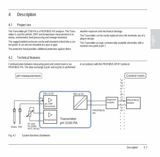
Proper use
The Transmitter pH
2100 PA is a PROFIBUS-PA analyzer. The Trans-mitter is used for pH/mV, ORP and temperature measurement in in-dustry, environment, food processing and sewage treatment.
The rugged molded enclosure can be wall mounted or fixed into a con-trol panel. It can also be mounted at a post or pipe.
The protective hood provides additional protection against direct
weather exposure and mechanical damage.
The Transmitter can be easily replaced since the terminals are of a plug-in design.
The Transmitter accepts commercially available electrodes with a nominal zero point at pH 7.
4.2
Technical features
Communication between measuring point and control room is via
PROFIBUS-PA. The data exchange (cyclic and acyclic) is performed in accordance with the PROFIBUS-DP/V1 protocol.
Fig. 4.1
System functions (hardware)
PROFIBUS
DP
TransmitterpH 2100 PA
Glass
Sensocheck
Temperature
Pt 100/Pt 1000/NTC 30 kΩ
+
–
pH measurement Control room
EEx ia IIC EEx ia IIC
Segmentcoupler
PROFIBUSMaster
PROFIBUS-PA
Ref
pH, ORP
E-
8
Description
4.3
Communication model
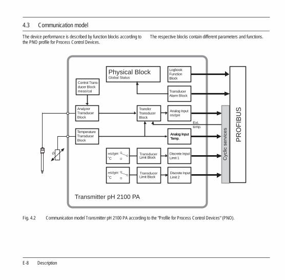
The device performance is described by function blocks according to
the PNO profile for Process Control Devices.The respective blocks contain different parameters and functions.
Fig. 4.2
Communication model Transmitter pH 2100 PA according to the “Profile for Process Control Devices“ (PNO).
Transmitter pH 2100 PA
Physical BlockGlobal Status
mV/pH˚C
mV/pH˚C
TransducerLimit Block
Ext.temp.
Control Trans-ducer Blockmeas/cal
AnalyzerTransducerBlock
TemperatureTransducerBlock
TransferTransducerBlock
TransducerLimit Block
TransducerAlarm Block
Analog InputmV/pH
Analog InputTemp.Analog InputTemp.
Discrete InputLimit 1
Discrete InputLimit 2
LogbookFunctionBlock
Cyc
lic s
ervi
ces
PR
OF
IBU
S
Description
E-
9
Engl
ish
4.4
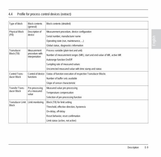
Profile for process control devices (extract)
Type of block
Block contents
(general)Block contents (detailed)
Physical Block
(PB)Description of device
Measurement procedure, device configuration
Serial number, manufacturer name
Operating state (run, maintenance, ...)
Global status, diagnostics information
Transducer Block (TB)
Measurement procedure with interpretation
Process variable (plain text and unit)
Number of measurement ranges (MR), start and end value of MR, active MR
Autorange function On/Off
Sampling rate of measured values
Uncorrected measured value with time stamp and status
Control Trans-ducer Block
Control of device functions
Status of function execution of respective Transducer Blocks
Number of buffer sets available
Slope of sensor characteristic
Transfer Trans-ducer Block
Pre-processing of a measured value
Measured value pre-processing
Temperature compensation
Selection of pre-processing function
Transducer Limit Block
Limit monitoring Block (TB) for limit setting
Threshold, effective direction, hysteresis
On-delay, off-delay
Reset behavior, reset confirmation
Limit status (active, not active)

E-
10
Description
T
ab. 4.1: Profile for Process Control Devices (function contents)
Analog Input (AI)
Function Block
Measured value
Currently measured value with status and range
Rise time, hysteresis of AI limits
Upper/lower alarm limit
Upper/lower warning limit
Switchover manual/automatic operation, measured value simulation
Fail-safe behavior
Discrete Input
(DI)
Function Block
Digital input Switchover manual/automatic operation
Limit value message/status
Signal inversion
Fail-safe behavior
Transducer Alarm Block
Signaling of states and events
Required maintenance, function check, errors, limits incl. cumulative message
Logbook Func-tion Block
Registration of states and events
Power on, power off, reset
State of execution
Navigation through entries
Type of block
Block contents
(general)
Block contents (detailed)

Assembly
E-
11
Engl
ish
5
Assembly
5.1
Package contents and unpacking
Unpack the Transmitter carefully. Check the shipment for transport
damage and completeness.
The package should contain:
- Front unit of Transmitter
- Lower case
- This instruction manual
- Short instruction sheet
- Floppy disk with GSD file METT7533.GSD
- Bag containing small parts:
Fig. 5.1
Assembling the enclosure
1
Jumper (1
piece)
2 Washer (1 piece): for conduit mount-ing: Place washer between enclosure and nut
3 Cable ties (3 pieces)
4 Hinge pin (1 piece): insertable from either side
5 Enclosure screws (4 pieces)
6 Sealing inserts (3 pieces)
7 Rubber reducer (1 piece)
8 Cable glands (3 pieces)
9 Filler plugs (3 pieces)
10 Gaskets (3 pieces)
11 Hexagon nuts (3 pieces)
12 Sealing plugs (2 pieces): for sealing in case of wall mounting
12
11
10
9
8
7 6 5 4
1
2
3

E-
12
Assembly
5.2
Mounting plan
Fig. 5.2
Mounting plan
1
Cable glands (3
pieces)
2 Breakthroughs for cable gland or conduit 1/2”, ø = 21.5 mm (2 breakthroughs)
Cable glands and conduit glands not included!
3 Breakthroughs for pipe mounting (4 breakthroughs)
4 Breakthroughs for wall mounting (2 breakthroughs)
14414
418 42
84
8032
21
43
105
27
726.
2
1 2
3
4
Assembly
E-
13
Engl
ish
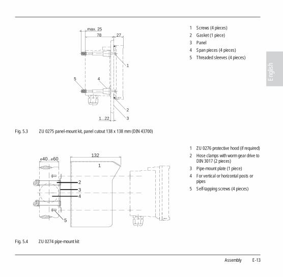
Fig. 5.3
ZU 0275 panel-mount kit, panel cutout 138 x 138 mm (DIN 43700)
Fig. 5.4 ZU 0274 pipe-mount kit
1
Screws (4 pieces)
2 Gasket (1 piece)
3 Panel
4 Span pieces (4 pieces)
5 Threaded sleeves (4 pieces)
1
2
3
45
max. 2578 27
1...22
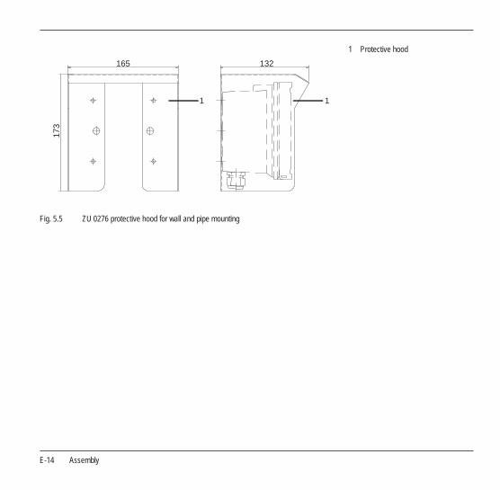
1 ZU 0276 protective hood (if required)
2 Hose clamps with worm gear drive to DIN 3017 (2 pieces)
3 Pipe-mount plate (1 piece)
4 For vertical or horizontal posts or pipes
5 Self-tapping screws (4 pieces)
40 60132
1
2
34
5
E-14 Assembly
Fig. 5.5 ZU 0276 protective hood for wall and pipe mounting
1 Protective hood
1
13216517
3
1
Installation and connection E-15
Engl
ish
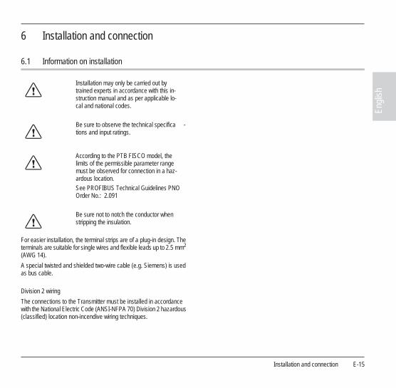
6 Installation and connection
6.1 Information on installation
For easier installation, the terminal strips are of a plug-in design. The terminals are suitable for single wires and flexible leads up to 2.5 mm2 (AWG 14).
A special twisted and shielded two-wire cable (e.g. Siemens) is used as bus cable.
Division 2 wiring
The connections to the Transmitter must be installed in accordance with the National Electric Code (ANSI-NFPA 70) Division 2 hazardous (classified) location non-incendive wiring techniques.
Installation may only be carried out by trained experts in accordance with this in-struction manual and as per applicable lo-cal and national codes.
Be sure to observe the technical specifica -tions and input ratings.
According to the PTB FISCO model, the limits of the permissible parameter range must be observed for connection in a haz-ardous location.See PROFIBUS Technical Guidelines PNO Order No.: 2.091
Be sure not to notch the conductor when stripping the insulation.
E-16 Installation and connection
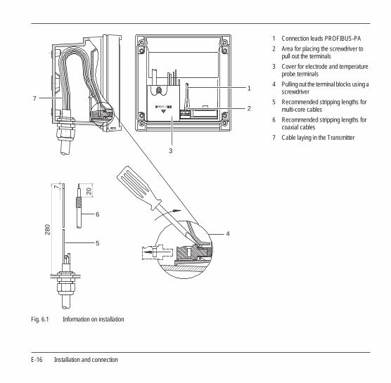
Fig. 6.1 Information on installation
1 Connection leads PROFIBUS-PA
2 Area for placing the screwdriver to pull out the terminals
3 Cover for electrode and temperature probe terminals
4 Pulling out the terminal blocks using a screwdriver
5 Recommended stripping lengths for multi-core cables
6 Recommended stripping lengths for coaxial cables
7 Cable laying in the Transmitter
7
1
2
3
20
728
0
6
5
4

Installation and connection E-17
Engl
ish
6.2 Terminal assignments
Fig. 6.2 Terminal assignments of the Transmitter
6.3 Overview of the Transmitter pH 2100 PA
Fig. 6.3 Inputs and outputs
1 Inputs for glass and reference elec-trode
2 Input for temperature probe
3 PROFIBUS-PA
Temperature TransmitterpH 2100 PA
pH, mVSensocheck
EEx ia IIC EEx ia IIC
1
2
3
E-18 Installation and connection
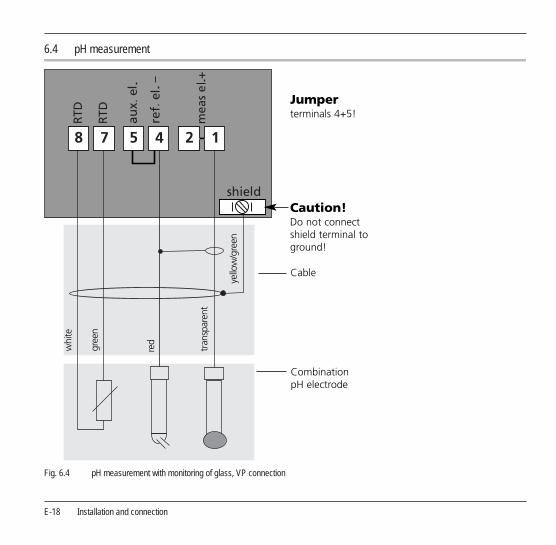
6.4 pH measurement
Fig. 6.4 pH measurement with monitoring of glass, VP connection
Installation and connection E-19
Engl
ish
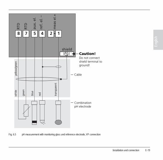
Fig. 6.5 pH measurement with monitoring glass and reference electrode, VP connection
E-20 Installation and connection
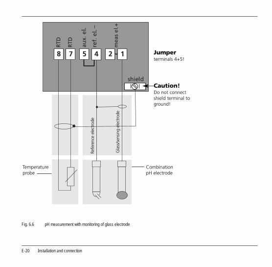
Fig. 6.6 pH measurement with monitoring of glass electrode

Installation and connection E-21
Engl
ish
Fig. 6.7 pH measurement with monitoring of glass and reference electrode

E-22 Installation and connection
6.5 ORP measurement
Fig. 6.8 ORP measurement without monitoring of reference electrode
Commissioning E-23
Engl
ish
7 Commissioning
7.1 Checklist
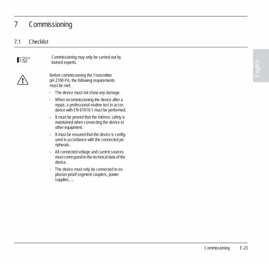
Commissioning may only be carried out by trained experts.
Before commissioning the Transmitter pH 2100 PA, the following requirements must be met:
- The device must not show any damage.
- When recommissioning the device after a repair, a professional routine test in accor-dance with EN 61010-1 must be performed.
- It must be proved that the intrinsic safety is maintained when connecting the device to other equipment.
- It must be ensured that the device is config-ured in accordance with the connected pe-ripherals.
- All connected voltage and current sources must correspond to the technical data of the device.
- The device must only be connected to ex-plosion-proof segment couplers, power supplies, ...
E-24 Operation
8 Operation
8.1 Operation possibilities
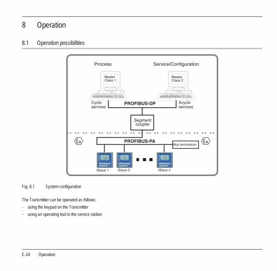
Fig. 8.1 System configuration
The Transmitter can be operated as follows:
- using the keypad on the Transmitter
- using an operating tool in the service station

Operation E-25
Engl
ish
8.2 Operation using keypad on the Transmitter
Fig. 8.2 Front view of the Transmitter pH 2100 PA
1 Display
2 Mode indicators (no keys)
- Measuring mode
- Calibration mode
- Alarm
- PROFIBUS-PA communication
- Configuration mode
3 Keypad
4 Coding
5 Model designation
6 Rating plate
1
2
3
4
56
METTLER TOLEDO
E-26 Operation
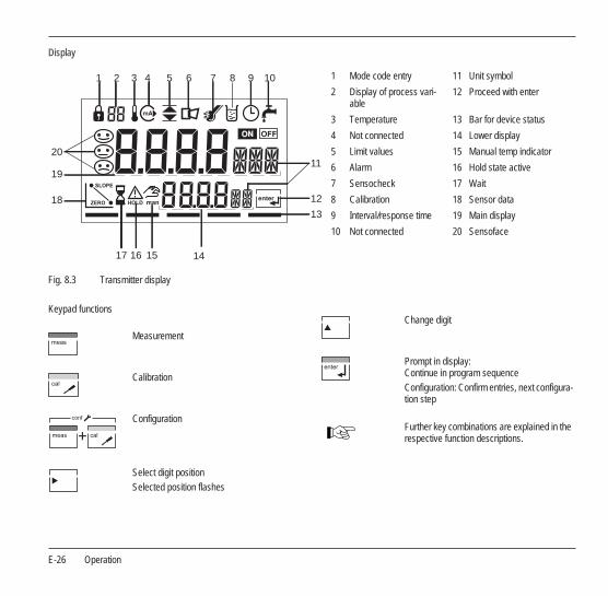
Display
Fig. 8.3 Transmitter display
Keypad functions
1 Mode code entry 11 Unit symbol
2 Display of process vari-able
12 Proceed with enter
3 Temperature 13 Bar for device status
4 Not connected 14 Lower display
5 Limit values 15 Manual temp indicator
6 Alarm 16 Hold state active
7 Sensocheck 17 Wait
8 Calibration 18 Sensor data
9 Interval/response time 19 Main display
10 Not connected 20 Sensoface
1 2 3 4 5 6 7 8 9 10
11
12
13
1617
20
18
19
15 14
Measurement
Calibration
Configuration
Select digit positionSelected position flashes
conf
Change digit
Prompt in display: Continue in program sequenceConfiguration: Confirm entries, next configura-tion step
Further key combinations are explained in the respective function descriptions.
Operation E-27
Engl
ish
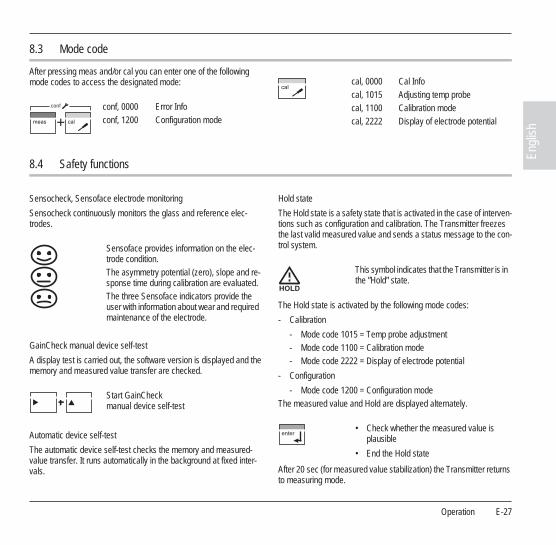
8.3 Mode code
After pressing meas and/or cal you can enter one of the following mode codes to access the designated mode:
8.4 Safety functions
Sensocheck, Sensoface electrode monitoring
Sensocheck continuously monitors the glass and reference elec-trodes.
GainCheck manual device self-test
A display test is carried out, the software version is displayed and the memory and measured value transfer are checked.
Automatic device self-test
The automatic device self-test checks the memory and measured-value transfer. It runs automatically in the background at fixed inter-vals.
Hold state
The Hold state is a safety state that is activated in the case of interven-tions such as configuration and calibration. The Transmitter freezes the last valid measured value and sends a status message to the con-trol system.
The Hold state is activated by the following mode codes:
- Calibration
- Mode code 1015 = Temp probe adjustment- Mode code 1100 = Calibration mode- Mode code 2222 = Display of electrode potential
- Configuration
- Mode code 1200 = Configuration modeThe measured value and Hold are displayed alternately.
After 20 sec (for measured value stabilization) the Transmitter returns to measuring mode.
conf, 0000conf, 1200
Error InfoConfiguration mode
conf
cal, 0000cal, 1015cal, 1100cal, 2222
Cal InfoAdjusting temp probeCalibration modeDisplay of electrode potential
Sensoface provides information on the elec-trode condition.The asymmetry potential (zero), slope and re-sponse time during calibration are evaluated.The three Sensoface indicators provide the user with information about wear and required maintenance of the electrode.
Start GainCheck manual device self-test
This symbol indicates that the Transmitter is in the ”Hold” state.
• Check whether the measured value is plausible
• End the Hold state
E-28 Operation
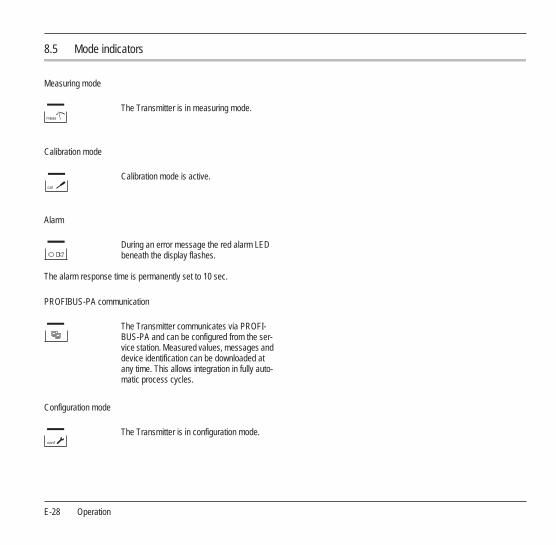
8.5 Mode indicators
Measuring mode
Calibration mode
Alarm
The alarm response time is permanently set to 10 sec.
PROFIBUS-PA communication
Configuration mode
The Transmitter is in measuring mode.
Calibration mode is active.
During an error message the red alarm LED beneath the display flashes.
The Transmitter communicates via PROFI-BUS-PA and can be configured from the ser-vice station. Measured values, messages and device identification can be downloaded at any time. This allows integration in fully auto-matic process cycles.
The Transmitter is in configuration mode.

Operation E-29
Engl
ish
8.6 Configuration
In the configuration mode the device parameters are set.
The following steps must be executed:
• Activate configuration
• Enter mode code ”1200”
• Confirm
Welcome text 3 sec
During configuration the Transmitter remains in the Hold state for reasons of safety.
• Select or edit parameter
• Confirm entries
All configurable parameters are shown in the table ”Configuration parameters” Pg. 30.
The configuration parameters are checked during the input.
conf
In the case of an incorrect input ”Err” is dis-played for approx. 3 sec. The incorrect param-eters cannot be stored. Input must be repeated.
• End configuration
The measured value and Hold are displayed alternately.
• End the Hold state / accept configuration or
• repeat configurationconf
E-30 Operation
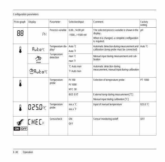
Configuration parameters
Picto-graph Display Parameter Selection/input Comment Factory setting
Process variable 0.00...14.00 pH
-1500...+1500 mV
The selected process variable is shown in the display.
When it is changed, a complete configuration is required.
pH
Temperature dis-play/
Temperature detection
Auto ˚C
Auto ˚F
Automatic detection during measurement and calibration (temp probe must be connected)
Auto ˚C
man ˚C
man ˚F
Manual input during measurement and cali-bration
˚C Auto man
˚F Auto man
Automatic detection during measurement, manual input during calibration
Temperature probe
Pt 100
Pt 1000
NTC 30
Selection of temperature probe PT 1000
BUS EXT External temp during measurement [˚C]
Manual input during calibration [˚C]
Temperature probe
xxx.x ˚C
xxx.x ˚F
Input of manual temperature 025.0 ˚C
Sensocheck ON
OFF
Sensor monitoring on/off OFF

Operation E-31
Engl
ish
Calibration mode:
Buffer set selec-tion
Mettler-Toledo Calibration mode: Automatic with Calimatic
BUF -01-
Merck Titrisols, Riedel Fixanals
Ciba (94)
NIST technical buffers
NIST standard buffers
HACH buffers
Customer-specific buffer solutions
Calibration with manual buffer entry
Direct entry of zero and slope of premeasured electrodes
Picto-graph Display Parameter Selection/input Comment Factory setting
Calibration mode
E-32 Operation
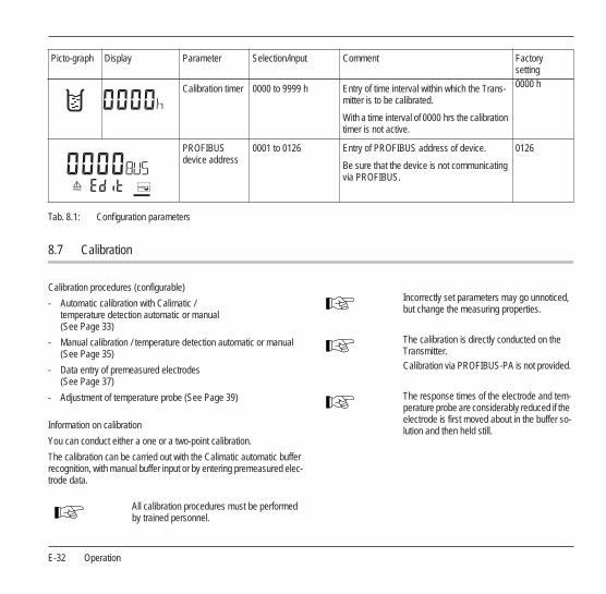
Tab. 8.1: Configuration parameters
8.7 Calibration
Calibration procedures (configurable)
- Automatic calibration with Calimatic / temperature detection automatic or manual (See Page 33)
- Manual calibration / temperature detection automatic or manual (See Page 35)
- Data entry of premeasured electrodes (See Page 37)
- Adjustment of temperature probe (See Page 39)
Information on calibration
You can conduct either a one or a two-point calibration.
The calibration can be carried out with the Calimatic automatic buffer recognition, with manual buffer input or by entering premeasured elec-trode data.
Calibration timer 0000 to 9999 h Entry of time interval within which the Trans-mitter is to be calibrated.
With a time interval of 0000 hrs the calibration timer is not active.
0000 h
PROFIBUS device address
0001 to 0126 Entry of PROFIBUS address of device.
Be sure that the device is not communicating via PROFIBUS.
0126
Picto-graph Display Parameter Selection/input Comment Factory setting
All calibration procedures must be performed by trained personnel.
Incorrectly set parameters may go unnoticed, but change the measuring properties.
The calibration is directly conducted on the Transmitter.Calibration via PROFIBUS-PA is not provided.
The response times of the electrode and tem-perature probe are considerably reduced if the electrode is first moved about in the buffer so-lution and then held still.

Operation E-33
Engl
ish
Automatic calibration with Calimatic (BUF -XX-) / temperature detection automatic or manual
The following steps must be executed:
The Transmitter can only operate properly when the buffer solutions used correspond to the configured set.Other buffer solutions, even those with the same nominal values, may demonstrate a dif-ferent temperature behavior. This leads to measurement errors.
During calibration the Transmitter remains in the Hold state for reasons of safety.
In the case of an incorrect input ”Err” is dis-played for approx. 3 sec. The incorrect param-eters cannot be stored. Input must be repeated.
For keypad functions refer to Pg. 26.
The automatic calibration mode and the type of temperature detection must be preset in the configuration mode. See table 8.6 ”Configura-tion” Pg. 29
• Activate calibration
• Enter mode code ”1100”
• Confirm
Welcome text 3 sec
During calibration the Transmitter remains in the Hold state for reasons of safety.
• Remove the electrode and temperature probe, clean them and immerse them in the first buffer solution
It does not matter which buffer solution is taken first.
E-34 Operation
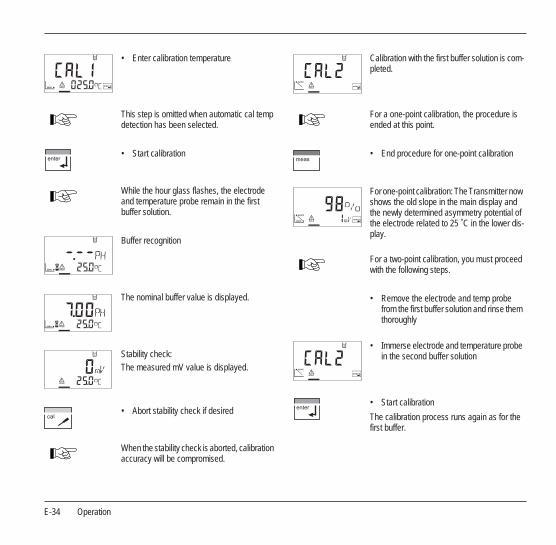
• Enter calibration temperature
This step is omitted when automatic cal temp detection has been selected.
• Start calibration
While the hour glass flashes, the electrode and temperature probe remain in the first buffer solution.
Buffer recognition
The nominal buffer value is displayed.
Stability check:The measured mV value is displayed.
• Abort stability check if desired
When the stability check is aborted, calibration accuracy will be compromised.
Calibration with the first buffer solution is com-pleted.
For a one-point calibration, the procedure is ended at this point.
• End procedure for one-point calibration
For one-point calibration: The Transmitter now shows the old slope in the main display and the newly determined asymmetry potential of the electrode related to 25 ˚C in the lower dis-play.
For a two-point calibration, you must proceed with the following steps.
• Remove the electrode and temp probe from the first buffer solution and rinse them thoroughly
• Immerse electrode and temperature probe in the second buffer solution
• Start calibration
The calibration process runs again as for the first buffer.
Operation E-35
Engl
ish
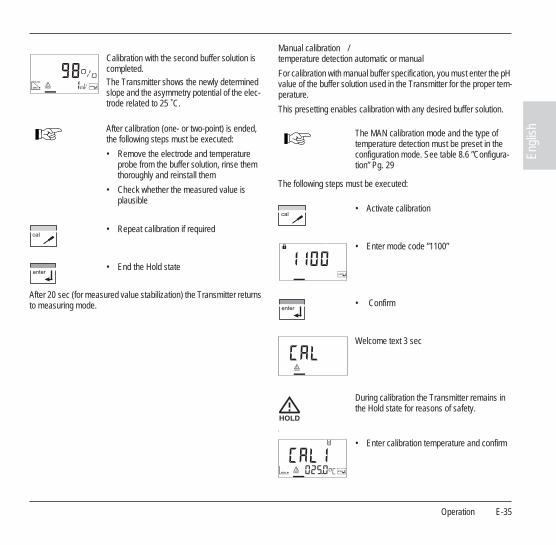
After 20 sec (for measured value stabilization) the Transmitter returns to measuring mode.
Manual calibration / temperature detection automatic or manual
For calibration with manual buffer specification, you must enter the pH value of the buffer solution used in the Transmitter for the proper tem-perature.
This presetting enables calibration with any desired buffer solution.
The following steps must be executed:
l
Calibration with the second buffer solution is completed.The Transmitter shows the newly determined slope and the asymmetry potential of the elec-trode related to 25 ˚C.
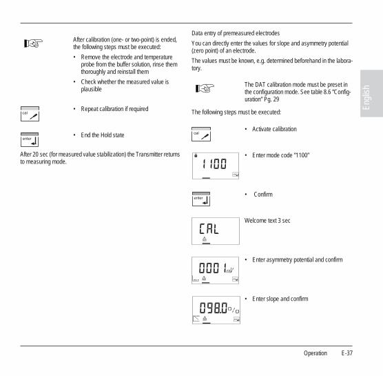
After calibration (one- or two-point) is ended, the following steps must be executed:
• Remove the electrode and temperature probe from the buffer solution, rinse them thoroughly and reinstall them
• Check whether the measured value is plausible
• Repeat calibration if required
• End the Hold state
The MAN calibration mode and the type of temperature detection must be preset in the configuration mode. See table 8.6 ”Configura-tion” Pg. 29
• Activate calibration
• Enter mode code ”1100”
• Confirm
Welcome text 3 sec
During calibration the Transmitter remains in the Hold state for reasons of safety.
• Enter calibration temperature and confirm
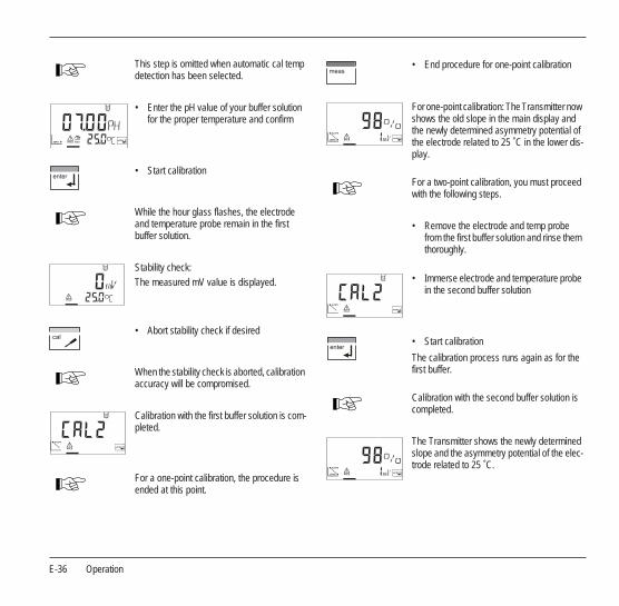
E-36 Operation
This step is omitted when automatic cal temp detection has been selected.
• Enter the pH value of your buffer solution for the proper temperature and confirm
• Start calibration
While the hour glass flashes, the electrode and temperature probe remain in the first buffer solution.
Stability check:The measured mV value is displayed.
• Abort stability check if desired
When the stability check is aborted, calibration accuracy will be compromised.
Calibration with the first buffer solution is com-pleted.
For a one-point calibration, the procedure is ended at this point.
• End procedure for one-point calibration
For one-point calibration: The Transmitter now shows the old slope in the main display and the newly determined asymmetry potential of the electrode related to 25 ˚C in the lower dis-play.
For a two-point calibration, you must proceed with the following steps.
• Remove the electrode and temp probe from the first buffer solution and rinse them thoroughly.
• Immerse electrode and temperature probe in the second buffer solution
• Start calibration
The calibration process runs again as for the first buffer.
Calibration with the second buffer solution is completed.
The Transmitter shows the newly determined slope and the asymmetry potential of the elec-trode related to 25 ˚C.
Operation E-37
Engl
ish
After 20 sec (for measured value stabilization) the Transmitter returns to measuring mode.
Data entry of premeasured electrodes
You can directly enter the values for slope and asymmetry potential (zero point) of an electrode.
The values must be known, e.g. determined beforehand in the labora-tory.
The following steps must be executed:
After calibration (one- or two-point) is ended, the following steps must be executed:
• Remove the electrode and temperature probe from the buffer solution, rinse them thoroughly and reinstall them
• Check whether the measured value is plausible
• Repeat calibration if required
• End the Hold state
The DAT calibration mode must be preset in the configuration mode. See table 8.6 ”Config-uration” Pg. 29
• Activate calibration
• Enter mode code ”1100”
• Confirm
Welcome text 3 sec
• Enter asymmetry potential and confirm
• Enter slope and confirm

E-38 Operation
After 20 sec (for measured value stabilization) the Transmitter returns to measuring mode.
Convert slope [%] to slope [mV/pH] at 25 ˚C:
Tab. 8.2: Slope conversion table at 25 ˚C
The Transmitter shows the new slope and the asymmetry potential of the electrode related to 25 ˚C.
• Check whether the measured value is plausible and repeat adjustment if required
• Repeat calibration if required
• End the Hold state
% 78 80 82 84 86 88 90 92 94 96 98 100 102
mV/pH 46.2 47.4 48.5 49.7 50.9 52.1 53.3 54.5 55.6 56.8 58.0 59.2 60.4
Operation E-39
Engl
ish
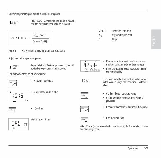
Convert asymmetry potential to electrode zero point:
Fig. 8.4 Conversion formula for electrode zero point
Adjustment of temperature probe
The following steps must be executed:
After 20 sec (for measured value stabilization) the Transmitter returns to measuring mode.
PROFIBUS-PA transmits the slope in mV/pH and the electrode zero point as pH value.
ZERO Electrode zero point
VAS Asymmetry potential
S SlopeZERO = 7 -VAS [mV]
S [mV / pH]
Especially for Pt 100 temperature probes, it is advisable to perform an adjustment.
• Activate calibration
• Enter mode code ”1015”
• Confirm
Welcome text 3 sec
• Measure the temperature of the process medium using an external thermometer
• Enter the determined temperature value in the main display
If you take over the temperature value shown in the lower display, the correction is without effect.
• Confirm the temperature value
• Check whether the measured value is plausible
• Repeat temperature adjustment if required
• End the Hold state
E-40 Operation
8.8 Operating tool
For parameter setting, commissioning and diagnostics of the Trans-mitter via PROFIBUS, we recommend operating tools such as SI-MATIC-PDM Version 5 or higher.
The current device description is included.
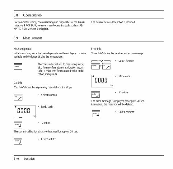
8.9 Measurement
Measuring mode
In the measuring mode the main display shows the configured process variable and the lower display the temperature.
Cal Info
”Cal Info” shows the asymmetry potential and the slope.
The current calibration data are displayed for approx. 20 sec.
Error Info
”Error Info” shows the most recent error message.
The error message is displayed for approx. 20 sec. Afterwards, the message will be deleted.
The Transmitter returns to measuring mode, also from configuration or calibration mode (after a relax time for measured-value stabili-zation, if required).
• Select function
• Mode code
• Confirm
• End ”Cal Info”
• Select function
• Mode code
• Confirm
• End ”Error Info”
conf
Operation E-41
Engl
ish
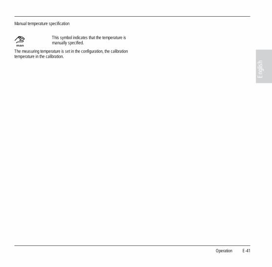
Manual temperature specification
The measuring temperature is set in the configuration, the calibration temperature in the calibration.
This symbol indicates that the temperature is manually specified.

E-42 Diagnostics
9 Diagnostics
9.1 Sensocheck, Sensoface
Sensocheck continuously monitors the glass and reference elec-trodes.
Sensocheck can be switched off.
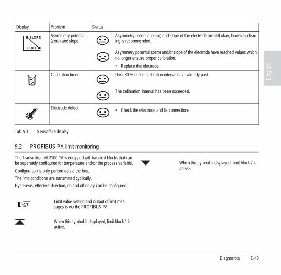
Sensoface displays
Sensoface provides information on the elec-trode condition.The asymmetry potential (zero), slope and re-sponse time during calibration are evaluated.The three Sensoface indicators provide the user with information about wear and required maintenance of the electrode.
A friendly Smiley can only be displayed when Sensocheck has been activated.
The basis for accurate Sensoface indication is proper calibration.
The worsening of a Sensoface criterion leads to the devaluation of the Sensoface indicator (average/poor).
An improvement of the Sensoface indicator can only take place after calibration or removal of an electrode defect.
The Sensoface status does not influence the measured value display.
Display Problem Status
Electrode response time
The electrode adjusts slowly to the measured value.
• Clean the electrode
• Soak it in buffer for several hours
• Replace electrode if there is no improvement
The electrode adjusts very slowly to the measured value. Correct measurement is no longer ensured.
• Replace the electrode
Diagnostics E-43
Engl
ish
Tab. 9.1: Sensoface display
9.2 PROFIBUS-PA limit monitoring
The Transmitter pH 2100 PA is equipped with two limit blocks that can be separately configured for temperature and/or the process variable.
Configuration is only performed via the bus.
The limit conditions are transmitted cyclically.
Hysteresis, effective direction, on and off delay can be configured.
Asymmetry potential (zero) and slope
Asymmetry potential (zero) and slope of the electrode are still okay, however clean-ing is recommended.
Asymmetry potential (zero) and/or slope of the electrode have reached values which no longer ensure proper calibration.
• Replace the electrode
Calibration timer Over 80 % of the calibration interval have already past.
The calibration interval has been exceeded.
Electrode defect • Check the electrode and its connections
Display Problem Status
Limit value setting and output of limit mes-sages is via the PROFIBUS-PA.
When this symbol is displayed, limit block 1 is active.
When this symbol is displayed, limit block 2 is active.
E-44 Diagnostics
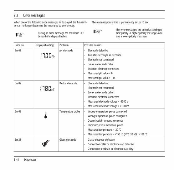
9.3 Error messages
When one of the following error messages is displayed, the Transmit-ter can no longer determine the measured value correctly.
The alarm response time is permanently set to 10 sec.
During an error message the red alarm LED beneath the display flashes.
The error messages are sorted according to their priority. A higher-priority message over-lays a lower-priority message.
Error No. Display (flashing) Problem Possible causes
Err 01 pH electrode - Electrode defective
- Too little electrolyte in electrode
- Electrode not connected
- Break in electrode cable
- Incorrect electrode connected
- Measured pH value < 0
- Measured pH value > +14
Err 02 Redox electrode - Electrode defective
- Electrode not connected
- Break in electrode cable
- Incorrect electrode connected
- Measured electrode voltage < -1500 V
- Measured electrode voltage > +1500 V
Err 03 Temperature probe - Wrong temperature probe connected
- Wrong temperature probe configured
- Open circuit in temperature probe
- Short circuit in temperature probe
- Measured temperature < -20 ˚C
- Measured temperature > +150 ˚C (NTC 30 kΩ : +130 ˚C)
Err 33 Glass electrode - Glass electrode defective
- Connection cable or electrode cap defective
- Connection terminals or electrode cap dirty

Diagnostics E-45
Engl
ish
Tab. 9.2: Error messages
Err 34 Reference electrode - Reference electrode defective
- Connection cable or electrode cap defective
- Connection terminals or electrode cap dirty
- Jumper between terminal 4 and 5 missing
Err 98 System error - Memory error in device program (PROM defective)
- Measured value transmission defective
- Configuration or calibration data defective
• Completely reconfigure and calibrate the Transmitter
Err 99 Factory settings - EEPROM or RAM defective
- Error in factory settings
This error message normally should not occur as the data are protected from loss by multiple safety functions.
• Should it nevertheless occur, send in the Transmitter for repair
Error No. Display (flashing) Problem Possible causes
E-46 Diagnostics
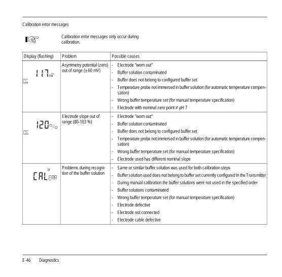
Calibration error messages
Calibration error messages only occur during calibration.
Display (flashing) Problem Possible causes
Asymmetry potential (zero) out of range (± 60 mV)
- Electrode "worn out"
- Buffer solution contaminated
- Buffer does not belong to configured buffer set
- Temperature probe not immersed in buffer solution (for automatic temperature compen-sation)
- Wrong buffer temperature set (for manual temperature specification)
- Electrode with nominal zero point ≠ pH 7
Electrode slope out of range (80-103 %)
- Electrode "worn out"
- Buffer solution contaminated
- Buffer does not belong to configured buffer set
- Temperature probe not immersed in buffer solution (for automatic temperature compen-sation)
- Wrong buffer temperature set (for manual temperature specification)
- Electrode used has different nominal slope
Problems during recogni-tion of the buffer solution
- Same or similar buffer solution was used for both calibration steps
- Buffer solution used does not belong to buffer set currently configured in the Transmitter
- During manual calibration the buffer solutions were not used in the specified order
- Buffer solutions contaminated
- Wrong buffer temperature set (for manual temperature specification)
- Electrode defective
- Electrode not connected
- Electrode cable defective

Diagnostics E-47
Engl
ish
Tab. 9.3: Calibration error messages
Calibration was canceled after approx. 2 minutes, because the electrode drift was too large.
- Electrode defective
- Electrode dirty
- No electrolyte in the electrode
- Electrode cable insufficiently shielded or defective
- Strong electric fields influence the measurement
- Major temperature fluctuation of the buffer solution
- No buffer solution or extremely diluted
Display (flashing) Problem Possible causes
E-48 Diagnostics
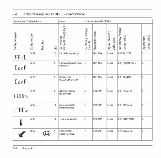
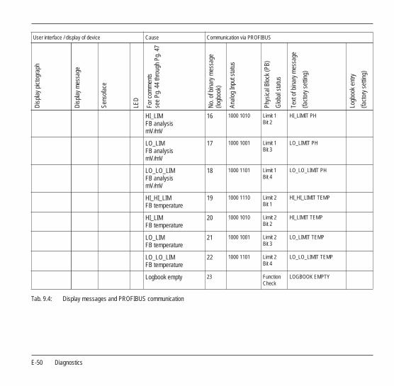
9.4 Display messages and PROFIBUS communication
User interface / display of device Cause Communication via PROFIBUS
Dis
play
pic
togr
aph
Dis
play
mes
sage
Sens
ofac
e
LED
For c
omm
ents
see
Pg. 4
4 th
roug
h Pg
. 47
No.
of b
inar
y m
essa
ge
(logb
ook)
Anal
og In
put s
tatu
s
Phys
ical
Blo
ck (P
B)
Glo
bal s
tatu
s
Text
of b
inar
y m
essa
ge
(fact
ory
setti
ng)
Logb
ook
entry
(fact
ory
setti
ng)
Err 99 X Error in factory settings 1 0001 11xx Failure ERR SYSTEM X
Err 98 X Error in configuration data, Gaincheck
2 0001 11xx Failure ERR PARAMETERS X
Err 98 X Memory error (RAM, ROM, EPROM)
3 0001 11xx Failure ERR MEMORY X
Err 01 X pH range violation (pH electrode)
4 0100 0111 Failure ERR PH VALUE X
Err 02 X mV range violation (redox electrode)
5 0100 0111 Failure ERR MV VALUE X
Err 03 X Temp range violation 6 0100 0111 Failure ERR TEMP VALUE X
Err 33 X Sensocheck Glass electrode
7 0100 0111 Failure CHK GLASS EL. X

Diagnostics E-49
Engl
ish
Err 34 X Sensocheck Reference electrode
8 0100 0111 Failure CHK REF. EL. X
Zero point/ slope
9 0101 00xx Mainte-nance required
CHK ZERO/SLOPE. X
Response time of electrode
10 0101 00xx Mainte-nance required
CHK EL. RESPONSE. X
Calibration timer Cal prompt
11 0101 00xx Mainte-nance required
CAL REQUIRED X
Calibration 12 0100 0111 Function check
CAL RUNNING X
Configuration 13 0100 0111 Function check
CONF RUNNING X
HOLD 14 0100 0111 Function check
HOLD X
HI_HI_LIM FB analysis mV/mV
15 1000 1110 Limit 1 Bit 1
HI_HI_LIMIT PH
User interface / display of device Cause Communication via PROFIBUS
Dis
play
pic
togr
aph
Dis
play
mes
sage
Sens
ofac
e
LED
For c
omm
ents
see
Pg. 4
4 th
roug
h Pg
. 47
No.
of b
inar
y m
essa
ge
(logb
ook)
Anal
og In
put s
tatu
s
Phys
ical
Blo
ck (P
B)
Glo
bal s
tatu
s
Text
of b
inar
y m
essa
ge
(fact
ory
setti
ng)
Logb
ook
entry
(fact
ory
setti
ng)
E-50 Diagnostics
Tab. 9.4: Display messages and PROFIBUS communication
HI_LIM FB analysis mV/mV
16 1000 1010 Limit 1 Bit 2
HI_LIMIT PH
LO_LIM FB analysis mV/mV
17 1000 1001 Limit 1 Bit 3
LO_LIMIT PH
LO_LO_LIM FB analysis mV/mV
18 1000 1101 Limit 1 Bit 4
LO_LO_LIMIT PH
HI_HI_LIM FB temperature
19 1000 1110 Limit 2 Bit 1
HI_HI_LIMIT TEMP
HI_LIM FB temperature
20 1000 1010 Limit 2 Bit 2
HI_LIMIT TEMP
LO_LIM FB temperature
21 1000 1001 Limit 2 Bit 3
LO_LIMIT TEMP
LO_LO_LIM FB temperature
22 1000 1101 Limit 2 Bit 4
LO_LO_LIMIT TEMP
Logbook empty 23 Function Check
LOGBOOK EMPTY
User interface / display of device Cause Communication via PROFIBUSD
ispl
ay p
icto
grap
h
Dis
play
mes
sage
Sens
ofac
e
LED
For c
omm
ents
see
Pg. 4
4 th
roug
h Pg
. 47
No.
of b
inar
y m
essa
ge
(logb
ook)
Anal
og In
put s
tatu
s
Phys
ical
Blo
ck (P
B)
Glo
bal s
tatu
s
Text
of b
inar
y m
essa
ge
(fact
ory
setti
ng)
Logb
ook
entry
(fact
ory
setti
ng)

Diagnostics E-51
Engl
ish
9.5 Diagnostics functions
Cal Info
”Cal Info” shows the asymmetry potential and the slope.
The current calibration data are displayed for approx. 20 sec.
Error Info
”Error Info” shows the most recent error message.
The error message is displayed for approx. 20 sec. Afterwards, the message will be deleted.
Display of electrode potential
During electrode maintenance it is useful to directly indicate the elec-trode potential. This allows, for example, to check electrode response after cleaning.
The electrode potential is displayed.
• Select function
• Mode code
• Confirm
• End ”Cal Info”
• Select function
• Mode code
• Confirm
conf
• End ”Error Info”
• Select function
• Enter mode code ”2222”
• Confirm
• End display mode
During electrode potential display the Trans-mitter is in the Hold state.

E-52 Diagnostics
GainCheck manual device self-test
A display test is carried out, the software version is displayed and the memory and measured value transfer are checked.
Automatic device self-test
The automatic device self-test checks the memory and measured-value transfer. It runs automatically in the background at fixed inter-vals.
Start GainCheck manual device self-test
Maintenance and cleaning E-53
Engl
ish
10 Maintenance and cleaning
10.1 Maintenance
The Transmitter contains no user repairable components.
10.2 Cleaning
To remove dust, dirt and spots, the external surfaces of the Transmit-ter may be wiped with a soft cloth moistened with water.
A mild household cleaner may also be used if necessary.

E-54 Maintenance and cleaning
Appendix E-55
Engl
ish
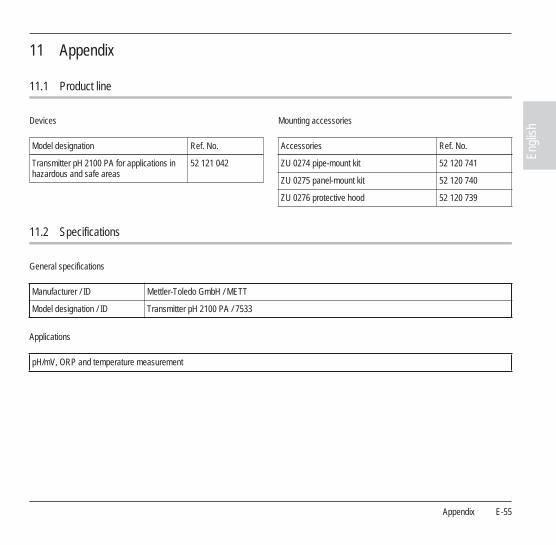
11 Appendix
11.1 Product line
Devices Mounting accessories
11.2 Specifications
General specifications
Applications
Model designation Ref. No.
Transmitter pH 2100 PA for applications in hazardous and safe areas
52 121 042
Accessories Ref. No.
ZU 0274 pipe-mount kit 52 120 741
ZU 0275 panel-mount kit 52 120 740
ZU 0276 protective hood 52 120 739
Manufacturer / ID Mettler-Toledo GmbH / METT
Model designation / ID Transmitter pH 2100 PA / 7533
pH/mV, ORP and temperature measurement

E-56 Appendix
input
Accuracy (± 1 count)
Monitoring function
Process vari-able
pH or mV (ORP)
Ranges pH value 0.00 to +14.00
mV value -1500 mV to +1500 mV
Glass electrode input Input resistance >0.5 x 10 12 Ω
Input current (20˚C) b
b) Doubles every 10 K
<2 x 10 -12 A
Reference electrode input Input resistance >1 x 10 10 Ω
Input current (20˚C) b <1 x 10 -10 A
Max. cable length Glass electrode 20 m
Temperature Temperature sensor a
a) Configurable
Pt100 / Pt1000 / NTC 30 kΩ
Ranges Pt100 / Pt1000 -20.0 to +150.0 ˚C / -4 to +302 ˚F
NTC 30 kΩ -20.0 to +130.0 ˚C / -4 to +266 ˚F
Resolution 0.1 ˚C / 1 ˚F
Temperature compensation a Automatic Pt100 / Pt1000 / NTC 30 kΩ
Manual input
pH value < 0.02 TC: <0.002 pH/K
mV value < 1 mV TC: <0.1 mV/K
Temperature 0.5 K (with Pt100 < 1 K, with NTC > 100 ˚C < 1 K)
Electrode Sensocheck (can be dis-abled)
Monitoring of glass and reference electrode
mV value Determination of alarm limits during calibration
Appendix E-57
Engl
ish
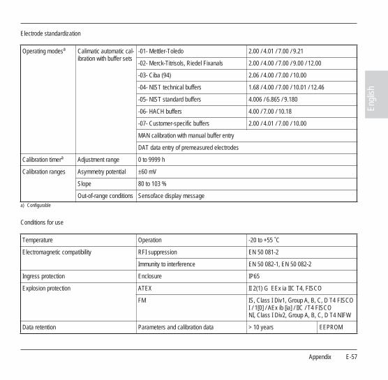
Electrode standardization
Conditions for use
Operating modesa
a) Configurable
Calimatic automatic cal-ibration with buffer sets
-01- Mettler-Toledo 2.00 / 4.01 / 7.00 / 9.21
-02- Merck-Titrisols, Riedel Fixanals 2.00 / 4.00 / 7.00 / 9.00 / 12.00
-03- Ciba (94) 2.06 / 4.00 / 7.00 / 10.00
-04- NIST technical buffers 1.68 / 4.00 / 7.00 / 10.01 / 12.46
-05- NIST standard buffers 4.006 / 6.865 / 9.180
-06- HACH buffers 4.00 / 7.00 / 10.18
-07- Customer-specific buffers 2.00 / 4.01 / 7.00 / 10.00
MAN calibration with manual buffer entry
DAT data entry of premeasured electrodes
Calibration timera Adjustment range 0 to 9999 h
Calibration ranges Asymmetry potential ±60 mV
Slope 80 to 103 %
Out-of-range conditions Sensoface display message
Temperature Operation -20 to +55 ˚C
Electromagnetic compatibility RFI suppression EN 50 081-2
Immunity to interference EN 50 082-1, EN 50 082-2
Ingress protection Enclosure IP65
Explosion protection ATEX II 2(1) G EEx ia IIC T4, FISCO
FM IS, Class I Div1, Group A, B, C, D T4 FISCO I / 1[0] / AEx ib [ia] / IIC / T4 FISCO NI, Class I Div2, Group A, B, C, D T4 NIFW
Data retention Parameters and calibration data > 10 years EEPROM

E-58 Appendix
Construction
Display and user interface
Dimensions Height 144 mm
Width 144 mm
Depth 105 mm
Weight Approx. 1 kg
Material PBT (polybutylene terephtalate)
Color Bluish gray RAL 7031
Assembly Wall mounting
Post/pipe mounting on pipe with 40 to 60 mm diameter, on square post with 30 to 45 mm edge length
Panel mounting Cutout to DIN 43 700
Sealed against panel
Electrical connection Cable glands 3 breakthroughs for included cable glands
2 breakthroughs for NPT 1/2” or Rigid Metallic Conduit or cable glands
Display LC display, 7-segment Measured value display pH / mV value, temperature
3 Sensoface states Good / average / poor
5 mode indicators meas / cal / alarm / online / conf
Alarm LED Error message
Operation 5 keys meas / cal / up / right / enter
Operating tool Device description implemented in SIMATIC PDM

Appendix E-59
Engl
ish
Remote interface
PROFIBUS-PA communication
Digital communication by current modulation of supply current Reading of device identification, measured values, status and message Reading and writing of parameter and configuration data
Protocol PROFIBUS-PA (DPV 1)
Connection via segment coupler or link to SPC, PC, PCS
Profile PNO directive: PROFIBUS-PA, Profile for Process Control Devices, Version 3.0
Physical interface
to IEC 1158-2
Address range 1 to 126, factory setting: 126
Supply voltage FISCO bus supply: 9 to 17.5 V
Linear barrier: (9 to 24 V)
Current consumption < 12.7 mA
Max. current in case of fault (FDE)
< 21.4 mA
E-60 Appendix
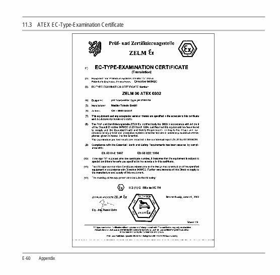
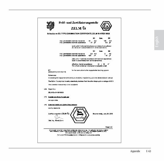
11.3 ATEX EC-Type-Examination Certificate

Appendix E-61
Engl
ish

E-62 Appendix
Appendix E-63
Engl
ish

E-64 Appendix
11.4 Declaration of Conformity
Declaration of conformity
Konformitätserklärung
Déclaration de conformité 0820
We/Wir/Nous Mettler-Toledo GmbH, Process Analytics Im Hackacker 15 8902 Urdorf Switzerland
declare under our sole responsibility that the product, erklären in alleiniger Verantwortung, dass dieses Produkt, déclarons sous notre seule responsabilité que le produit,
Description
Beschreibung/Description pH 2100 PA
to which this declaration relates is in conformity with the following standard(s) or othernormative document(s).auf welches sich diese Erklärung bezieht, mit der/den folgenden Norm(en) oder Richtlinie(n) übereinstimmt. auquel se réfère cette déclaration est conforme à la (aux) norme(s) ou au(x) document(s) normatif(s).
94/9/EG
Prüf- und Zertifizierungsstelle ZELM
ZELM 00 ATEX 0032
D-38124 Braunschweig, ZELM 0820
Explosionsschutzrichtlinie
Explosion Protection / Pro-
tection contre les explosions
89/336/EWG
SR 734.5, VEMV
EMC Directive/EMV-Richtlinie
Directive concernant la CEM
Low-voltage directve/Nieder-
spannungs-Richtlinie/
Directive basse tension73/23/EWG
SR 734.26, NEV
EN 50 014: 1997
EN 50 020: 1994
DIN EN 50 081-1 / VDE 0839 Teil 81-1: 1993-03
DIN EN 50 082-2 / VDE 0839 Teil 82-1: 1996-02
DIN EN 61326 / VDE 0843 Teil 20: 1998-01
DIN EN 61326 / A1 / VDE 0843 Teil 20 / A1: 1999-05
EN 60529 / 10.91 / VDE 0470 Teil 1: 1992-11
EN 61010 Teil 1 / 03.93 / VDE 0411 Teil 1: 1994-03
EN 61010-1/ A2 / 07.95 / VDE 0411 Teil 1 / A1: 1996-05
Norm/Standard/Standard
Place and Date of issue
Ausstellungsort / - Datum
Lieu et date d’émission Urdorf, August 2, 2004
Artikel Nr.: 52960164 KE Dateiname: 52960164KE-2100-PA-Internet-2.doc Version b
Mettler-Toledo GmbH, Process Analytics
Waldemar Rauch Christian Zwicky General Manager PO Urdorf Head of Marketing

Appendix E-65
Engl
ish
11.5 FM Control Drawing
!" #$ ! # !% # $ $ & !' $" $" #$ ! $ $ # !% # ! # $ ! # !( # ! # & )*+,- $ $ !' $" $" # *." /."0 & $ $ 1 )+,0 & 2( 342*)*)+51 (42+.*-51
426+/++5147458+)45$ 4745845$ ( 29+( 12*1( 2* 0 1 237:+*++7+//, 1 $ $ $ $
; 0 2' " " " $ % % 8 ( ( ( 8 ( (53 !(53 ( 53 # ( 53 !( 53 ( 53 # ; 2' " " " $ $ % % < = & 0 0 /)+ " " 050 3%*/+>+* ! ) #? -@ !# ( A B !05%0 C+# )+. )+) 0 ; 0 0 0 4 & -/*++%0$/*++ 0 *$ D +$ 0 EF 0 0 0 -/*++%0$-/*++ *$ D *$ *$ D /$ *$D + *$< *$ -@ !# ( ; 0 0 *) "$ +* 0 /) G
I
*
/
9.
)
>
C
6
:*+

E-66 Appendix
Appendix E-67
Engl
ish
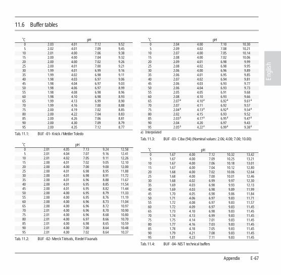
11.6 Buffer tables
Tab. 11.1: BUF -01- Knick / Mettler Toledo
Tab. 11.2: BUF -02- Merck Titrisols, Riedel Fixanals
Tab. 11.3: BUF -03- Ciba (94) (Nominal values: 2.06; 4.00; 7.00; 10.00)
Tab. 11.4: BUF -04- NIST technical buffers
˚C pH0 2.03 4.01 7.12 9.525 2.02 4.01 7.09 9.45
10 2.01 4.00 7.06 9.3815 2.00 4.00 7.04 9.3220 2.00 4.00 7.02 9.2625 2.00 4.01 7.00 9.2130 1.99 4.01 6.99 9.1635 1.99 4.02 6.98 9.1140 1.98 4.03 6.97 9.0645 1.98 4.04 6.97 9.0350 1.98 4.06 6.97 8.9955 1.98 4.08 6.98 8.9660 1.98 4.10 6.98 8.9365 1.99 4.13 6.99 8.9070 1.99 4.16 7.00 8.8875 2.00 4.19 7.02 8.8580 2.00 4.22 7.04 8.8385 2.00 4.26 7.06 8.8190 2.00 4.30 7.09 8.7995 2.00 4.35 7.12 8.77
˚C pH0 2.01 4.05 7.13 9.24 12.585 2.01 4.04 7.07 9.16 12.41
10 2.01 4.02 7.05 9.11 12.2615 2.00 4.01 7.02 9.05 12.1020 2.00 4.00 7.00 9.00 12.0025 2.00 4.01 6.98 8.95 11.8830 2.00 4.01 6.98 8.91 11.7235 2.00 4.01 6.96 8.88 11.6740 2.00 4.01 6.95 8.85 11.5445 2.00 4.01 6.95 8.82 11.4450 2.00 4.00 6.95 8.79 11.3355 2.00 4.00 6.95 8.76 11.1960 2.00 4.00 6.96 8.73 11.0465 2.00 4.00 6.96 8.72 10.9770 2.01 4.00 6.96 8.70 10.9075 2.01 4.00 6.96 8.68 10.8080 2.01 4.00 6.97 8.66 10.7085 2.01 4.00 6.98 8.65 10.5990 2.01 4.00 7.00 8.64 10.4895 2.01 4.00 7.02 8.64 10.37
˚C pH0 2.04 4.00 7.10 10.305 2.09 4.02 7.08 10.21
10 2.07 4.00 7.05 10.1415 2.08 4.00 7.02 10.0620 2.09 4.01 6.98 9.9925 2.08 4.02 6.98 9.9530 2.06 4.00 6.96 9.8935 2.06 4.01 6.95 9.8540 2.07 4.02 6.94 9.8145 2.06 4.03 6.93 9.7750 2.06 4.04 6.93 9.7355 2.05 4.05 6.91 9.6860 2.08 4.10 6.93 9.6665 2.07 a
a) Interpolated
4.10 a 6.92 a 9.61 a
70 2.07 4.11 6.92 9.5775 2.04 a 4.13 a 6.92 a 9.54 a
80 2.02 4.15 6.93 9.5285 2.03 a 4.17 a 6.95 a 9.47 a
90 2.04 4.20 6.97 9.4395 2.05 a 4.22 a 6.99 a 9.38 a
˚C pH0 1.67 4.00 7.12 10.32 13.425 1.67 4.00 7.09 10.25 13.21
10 1.67 4.00 7.06 10.18 13.0115 1.67 4.00 7.04 10.12 12.8020 1.68 4.00 7.02 10.06 12.6425 1.68 4.00 7.00 10.01 12.4630 1.68 4.02 6.99 9.97 12.3035 1.69 4.03 6.98 9.93 12.1340 1.69 4.03 6.98 9.89 11.9945 1.70 4.05 6.98 9.86 11.8450 1.71 4.06 6.97 9.83 11.7155 1.72 4.08 6.97 9.83 11.5760 1.72 4.09 6.97 9.83 11.4565 1.73 4.10 6.98 9.83 11.4570 1.74 4.13 6.99 9.83 11.4575 1.75 4.14 7.01 9.83 11.4580 1.77 4.16 7.03 9.83 11.4585 1.78 4.18 7.05 9.83 11.4590 1.79 4.21 7.08 9.83 11.4595 1.81 4.23 7.11 9.83 11.45

E-68 Appendix
Tab. 11.5: BUF -05- NIST standard buffersTab. 11.6: BUF -06- HACH buffers (Nominal values: 4.00; 7.00; 10.18)
Tab. 11.7: BUF -07- Customer-specific buffer solutions
˚C pH0 4.010 6.984 9.4645 4.004 6.951 9.395
10 4.000 6.923 9.33215 3.999 6.900 9.27620 4.001 6.881 9.22525 4.006 6.865 9.18030 4.012 6.853 9.13935 4.021 6.844 9.10240 4.031 6.838 9.06845 4.043 6.834 9.03850 4.057 6.833 9.01155 4.071 6.834 8.98560 4.087 6.836 8.96265 4.109 6.841 8.94270 4.126 6.845 8.92175 4.145 6.852 8.90380 4.164 6.859 8.88585 4.185 6.868 8.86890 4.205 6.877 8.85095 4.227 6.886 8.833
˚C pH0 4.00 7.14 10.305 4.00 7.10 10.23
10 4.00 7.04 10.1115 4.00 7.04 10.1120 4.00 7.02 10.0525 4.01 7.00 10.0030 4.01 6.99 9.9635 4.02 6.98 9.9240 4.03 6.98 9.8845 4.05 6.98 9.8550 4.06 6.98 9.8255 4.07 6.98 9.7960 4.09 6.99 9.7665 4.09 a
a) Values complemented (buffer values up to 60 ˚C as specified by Bergmann & Beving Process AB)
6.99 a 9.76 a
70 4.09 a 6.99 a 9.76 a
75 4.09 a 6.99 a 9.76 a
80 4.09 a 6.99 a 9.76 a
85 4.09 a 6.99 a 9.76 a
90 4.09 a 6.99 a 9.76 a
95 4.09 a 6.99 a 9.76 a
˚C ST 1 ST 2 ST 3 ST 50 2.03 4.01 7.12 10.655 2.02 4.01 7.09 10.52
10 2.01 4.00 7.06 10.3915 2.00 4.00 7.04 10.2620 2.00 4.00 7.02 10.1325 2.00 4.01 7.00 10.0030 1.99 4.01 6.99 9.8735 1.99 4.02 6.98 9.7440 1.98 4.03 6.97 9.6145 1.98 4.04 6.97 9.4850 1.98 4.06 6.97 9.3555 1.98 4.08 6.9860 1.98 4.10 6.9865 1.99 4.13 6.9970 2.00 4.16 7.0075 2.00 4.19 7.0280 2.00 4.22 7.0485 2.00 4.26 7.0690 2.00 4.30 7.0995 2.00 4.35 7.12
Appendix E-69
Engl
ish
11.7 Glossary
Asymmetry potential
The voltage which a pH electrode provides at a pH of 7. The asymmetry potential is different for each electrode and changes with age and wear.
Buffer set
Contains selected buffer solutions which can be used for auto-matic calibration with the Calimatic. The buffer set must be se-lected prior to the first calibration.
Buffer solution
Solution with an exactly defined pH value for calibrating a pH meter.
Calibration
Adjustment of the pH meter to the current electrode character-istics. The asymmetry potential and slope are adjusted. Either a one- or two-point calibration can be carried out. With one-point calibration only the asymmetry potential (zero point) is ad-justed.
Calibration buffer set
See buffer set
Calimatic
Automatic buffer recognition. Before the first calibration, the buffer set used must be activated once. The patented Calimatic then automatically recognizes the buffer solutions used during calibration.
Combination electrode
Combination of glass and reference electrode in one body.
Electrode
A pH electrode system consists of a glass and a reference elec-trode. If they are combined in one body, they are referred to as combination electrode.
Electrode slope
See slope
Electrode zero point
pH value at which the pH electrode outputs the voltage 0 mV. The zero point is different for each electrode and changes with age and wear.
FISCO Model (Fieldbus Intrinsically Safe Concept)
Permits connection of several devices to a common bus line and defines limit values for device and cable parameters. This model developed by the German PTB assumes that only one ”active” device, i.e. the bus supply is connected to the field bus. All other devices are ”passive” with regard to the power supply into the bus. Within the defined limits, the line characteristics have no influ-ence on the intrinsic safety.
GainCheck
Device self-test which runs automatically in the background at fixed intervals. The memory and measured-value transmission are checked. You can also start the GainCheck manually. Then a display test is also conducted and the software version dis-played.
GSD file (device database file)
Contains the communication parameters of slave devices. Dur-ing commissioning it is loaded and installed in the process con-trol system.
E-70 Appendix
Limit values
The Transmitter pH 2100 PA provides two limit blocks which can be assigned to the process variables pH/mV or C. The limit conditions are cyclically transmitted via PROFIBUS. Hystere-sis, effective direction, on and off delay can be configured via the PROFIBUS.
Link
A link collects the transmission data from the segment couplers and sends them in blocks to the control system.
Mode code
Preset four-digit number to select certain modes.
One-point calibration
Calibration with which only the asymmetry potential (zero point) is taken into account. The previous slope value is retained. Only one buffer solution is required for a one-point calibration.
PROFIBUS-DP (decentralized peripherals)
Standardized specification (EN 50 170) of an open fieldbus system for binary and analog signals of sensors and actuators. It has been designed for high-speed data exchange at the de-vice level.
PROFIBUS-PA (process automation)
Open fieldbus standard for process automation. It makes use of the transmission technology to IEC 1158-2 approved for opera-tion in hazardous locations, which at the same time allows the field devices to be powered over the bus.
Response time
Time from the start of calibration to the stabilization of the elec-trode potential.
Sensocheck
Sensocheck continuously monitors the glass and reference electrodes.
Sensoface
Provides information on the electrode condition.
SIMATIC-PDM
Tool developed by Siemens for projecting, configuring, com-missioning and diagnostic of smart process analyzers. The de-vice description for the Transmitter pH 2100 PA is implemented in the SIMATIC-PDM.
Slope
Is indicated in % of the theoretical slope (59.2 mV/pH at 25 ˚C). The electrode slope is different for each electrode and changes with age and wear.
Two-point calibration
Calibration with which the electrode asymmetry potential (zero point) and slope are determined. Two buffer solutions are re-quired for two-point calibration.
Zero point
See electrode zero point
Index E-71
Engl
ish
12 Index
AAccuracy, E-56
Adjusting temp probe, E-39
Analog Input (AI) Function Block, E-10
Applications, E-55
Assembly
Enclosure, E-11
Panel-mount kit (ZU 0275), E-13
Pipe-mount kit (ZU 0274), E-13
Protective hood (ZU 0276), E-14
Transmitter, E-12
Asymmetry potential
Converting, E-39
BBuffer tables, E-67
CCal Info, E-40, E-51
Calibration, E-32
Automatic
With automatic calibration temp detection, E-33
Manual
Data entry, E-37
With automatic calibration temp detection, E-35
Sensoface, E-42
Calibration error message, E-46
Certificate of Conformity, E-60
Cleaning
Transmitter, E-53
Commissioning, E-23
Conditions for use, E-57
Configuration, E-29
Connection, E-15
Examples, E-18, E-19, E-20, E-21, E-22
Lines, E-16
Construction, E-58
Control Transducer Block, E-9
Converting asymmetry potential, E-39
Converting slope, E-38
DDeclaration of Conformity, E-64
Device description, E-7
Device self-test
Automatic, E-27, E-52
Manual, E-27, E-52
Diagnostics functions, E-51
Discrete Input (DI) Function Block, E-10
Display, E-26
Display electrode potential, E-51
Display messages and PROFIBUS communication, E-48
Division 2 wiring, E-15
EElectrode standardization, E-57
Error Info, E-40, E-51
E-72 Index
Error message, E-44
Calibration, E-46
Explosion protection, E-4
FFM Control Drawing, E-65
GGainCheck, E-27, E-52
HHold state, E-27
IInstallation, E-15
KKeypad functions, E-26
LLimit monitoring
PROFIBUS-PA, E-43
Logbook Function Block, E-10
MMaintenance
Transmitter, E-53
Measurement, E-40
Measuring mode, E-40
Mode code, E-27, E-75
Mode indicators, E-28
Mounting plan, E-12
NNotes
Installation, E-15
This instruction manual, E-3
OOperating tool, E-40
Operation possibilities, E-24
ORP measurement, E-22
PPacking list, E-11
Panel-mount kit (ZU 0275), E-13
pH measurement, E-18, E-19, E-20, E-21
Physical Block (PB), E-9
Pipe-mount kit (ZU 0274), E-13
Process variable
Configuring, E-30
Product line
Devices, E-55
Mounting accessories, E-55
PROFIBUS
Variants, E-5
PROFIBUS technology, E-5
PROFIBUS-PA
Definitions, E-5
Limit monitoring, E-43
Proper use, E-7
Protective hood (ZU 0276), E-14

Index E-73
Engl
ish
SSafety functions, E-27
Safety information, E-4
Sensocheck, E-27, E-42
Sensoface, E-27, E-42
Calibration, E-42
Sensor monitoring, E-27
Slope
Converting, E-38
Specifications, E-55
Stripping lengths, E-16
TTechnical features, E-7
Temperature detection
Configuring, E-30
Temperature probe adjustment, E-39
Temperature specification
Manual, E-40, E-41, E-51
Terminal assignments, E-17
Transducer Alarm Block, E-10
Transducer Block (TB), E-9
Transducer Limit Block, E-9
Transfer Transducer Block, E-9
Transmitter pH 2100 PA
Overview, E-17
Type Examination Certificate, E-60
UUnpacking, E-11

E-74 Index
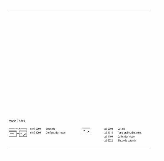
Mode Codes
conf, 0000conf, 1200
Error InfoConfiguration mode
conf cal, 0000cal, 1015cal, 1100cal, 2222
Cal InfoTemp probe adjustmentCalibration modeElectrode potential

Subject to technical changes.© Mettler-Toledo GmbH, Process Analytics06/05 Printed in Switzerland. 52 121 064
Mettler-Toledo GmbH, Process AnalyticsIndustrie Nord, CH-8902 Urdorf, SwitzerlandPhone + 41 44 736 22 11, Fax +41 44 736 26 36