Bedienungsanleitung Operating instructions - festo.com with the specifications in the chapter...
16
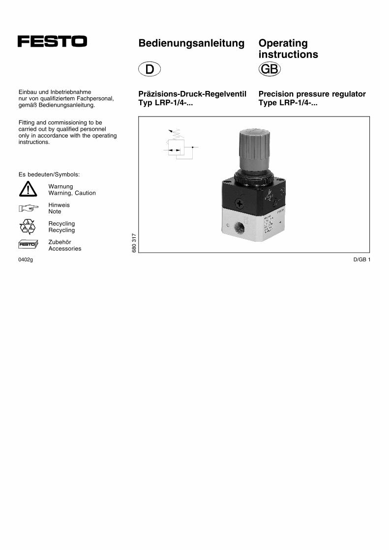
Bedienungsanleitung Präzisions-Druck-Regelventil Typ LRP-1/4-... Operating instructions Precision pressure regulator Type LRP-1/4-... Einbau und Inbetriebnahme nur von qualifiziertem Fachpersonal, gemäß Bedienungsanleitung. Fitting and commissioning to be carried out by qualified personnel only in accordance with the operating instructions. Es bedeuten/Symbols: Warnung Warning, Caution Hinweis Note Recycling Recycling Zubehör Accessories 680 317 0402g D/GB 1
Transcript of Bedienungsanleitung Operating instructions - festo.com with the specifications in the chapter...
Bedienungsanleitung
Präzisions-Druck-RegelventilTyp LRP-1/4-...
Operatinginstructions
Precision pressure regulatorType LRP-1/4-...
Einbau und Inbetriebnahmenur von qualifiziertem Fachpersonal,gemäß Bedienungsanleitung.
Fitting and commissioning to becarried out by qualified personnelonly in accordance with the operatinginstructions.
Es bedeuten/Symbols:
WarnungWarning, Caution
HinweisNote
RecyclingRecycling
ZubehörAccessories 68
031
7
0402g D/GB 1
�
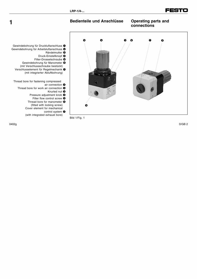
Bedienteile und Anschlüsse Operating parts andconnections
1
Gewindebohrung für Druckluftanschluss �Gewindebohrung für Arbeitsluftanschluss �
Rändelmutter �Druck-Einstellknopf �
Filter-Drosselschraube �Gewindebohrung für Manometer �
(mit Verschlussschraube bestückt)Verschlusselement für Regelmechanik �
(mit integrierter Abluftbohrung)
Thread bore for fastening compressedair connection �
Thread bore for work air connection �Knurled nut �
Pressure adjustment knob �Filter flow control screw �
Thread bore for manometer �(fitted with locking screw)
Cover element for mechanicalcontrol system �
(with integrated exhaust bore)
� � � � �
Bild 1/Fig. 1
�
LRP-1/4-...
0402g D/GB 2

Funktion und Anwendung
Das LRP-1/4 besteht aus einem Kam-mersystem mit zwei Membranen.An jeder Membran wirken beidseitigDruck- oder Federkräfte.Je nach Einstellung des Druck-Einstell-knopfes ergibt sich ein anderer Gleich-gewichtszustand.Bei Ungleichgewicht der Kräfte bewegensich die Membranen und der Ven-tilstößel hebt vom Ventilsitz ab.Druckluft strömt nach bis wieder derGleichgewichtszustand erreicht ist.
Das LRP-1/4-... ist bestimmungsgemäßfür präzise Einzeldruckregelung nachge-schalteter, pneumatischer Komponentenvorgesehen.
Function and application
The LRP-1/4 consists of a chamber sy-stem with two diaphragms.Pressure or spring forces operate onboth sides of each diaphragm.A different balance can be set depen-ding on the setting of the pressure knob.If the forces are not balanced, the dia-phragms will move and the valve stemwill lift up from the valve seat.Compressed air then flows in until ba-lance is achieved again.
The LRP-1/4-... is intended for preciseregulation of individual pressures onpneumatic components.
2
0402g D/GB 3
Voraussetzungen für denProdukteinsatz
Allgemeine, stets zu beachtende Hin-weise für den ordnungsgemäßen und si-cheren Einsatz des Produkts:
• Halten Sie die angegebenen Grenz-werte ein (z.B. für Drücke, Kräfte,Momente, Massen, Temperaturen).
• Sorgen Sie für ordnungsgemäß auf-bereitete Druckluft.
• Berücksichtigen Sie die vorherr-schenden Umgebungsbedingungen.
• Beachten Sie die Vorschriften derBerufsgenossenschaft, des Techni-schen Überwachungsvereins oderentsprechende nationale Bestimmun-gen.
• Entsorgen Sie Schutzvorrichtungenwie Kartonagen, Folien und Trans-portstopfen in Recycling-Sammelbe-hältern.
Safety conditions
These general conditions for the correctand safe use of the product must be ob-served at all times.
• Please observe the specified limits(e.g. for pressures, forces, torques,masses, speeds, temperatures).
• Please ensure that there is a supplyof correctly prepared compressed air.
• Please observe the prevailing am-bient conditions.
• Please comply with national andlocal safety laws and regulations.
• Remove all packaging such as pro-tective wax, foils, caps.The individual materials can be dis-posed of in recycling containers.
Bild 2/Fig. 2
3
LRP-1/4-...
0402g D/GB 4
• Behalten Sie die Zusammensetzungdes Mediums über die gesamte Pro-duktlebensdauer bei.
Medium: ungeölte Druckluftbeizubehalten: ungeölte Druckluft
• Belüften Sie Ihre gesamte Anlage lang-sam.
Dann treten keine unkontrollierten Be-wegungen auf.
• Verwenden Sie das Produkt im Origi-nalzustand ohne jegliche eigenmächti-ge Veränderung.
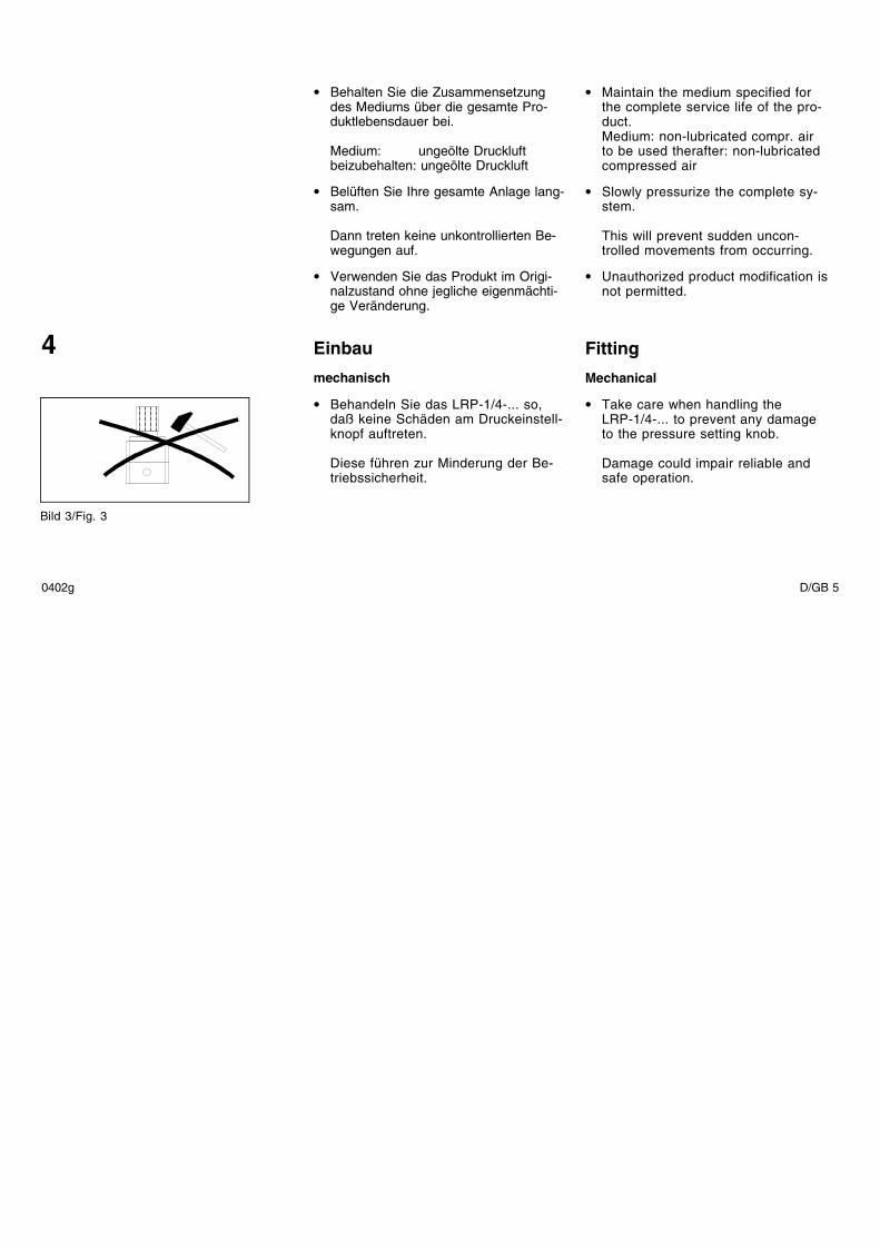
Einbau
mechanisch
• Behandeln Sie das LRP-1/4-... so,daß keine Schäden am Druckeinstell-knopf auftreten.
Diese führen zur Minderung der Be-triebssicherheit.
Bild 3/Fig. 3
• Maintain the medium specified forthe complete service life of the pro-duct.Medium: non-lubricated compr. airto be used therafter: non-lubricatedcompressed air
• Slowly pressurize the complete sy-stem.
This will prevent sudden uncon-trolled movements from occurring.
• Unauthorized product modification isnot permitted.
Fitting
Mechanical
• Take care when handling theLRP-1/4-... to prevent any damageto the pressure setting knob.
Damage could impair reliable andsafe operation.
4
0402g D/GB 5
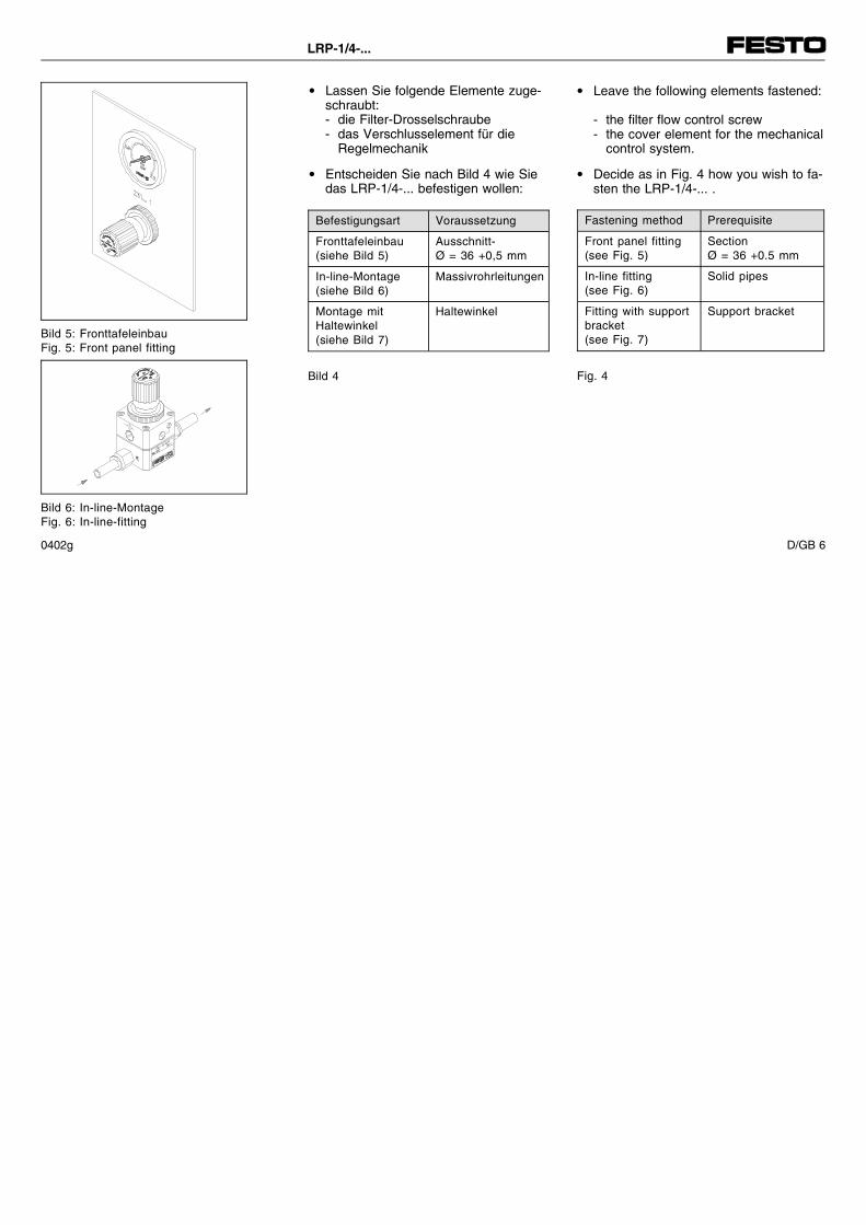
• Lassen Sie folgende Elemente zuge-schraubt:- die Filter-Drosselschraube- das Verschlusselement für die
Regelmechanik
• Entscheiden Sie nach Bild 4 wie Siedas LRP-1/4-... befestigen wollen:
• Leave the following elements fastened:
- the filter flow control screw- the cover element for the mechanical
control system.
• Decide as in Fig. 4 how you wish to fa-sten the LRP-1/4-... .
Befestigungsart Voraussetzung
Fronttafeleinbau(siehe Bild 5)
Ausschnitt-Ø = 36 +0,5 mm
In-line-Montage(siehe Bild 6)
Massivrohrleitungen
Montage mitHaltewinkel(siehe Bild 7)
Haltewinkel
Bild 4
Fastening method Prerequisite
Front panel fitting(see Fig. 5)
SectionØ = 36 +0.5 mm
In-line fitting(see Fig. 6)
Solid pipes
Fitting with supportbracket(see Fig. 7)
Support bracket
Fig. 4
Bild 5: FronttafeleinbauFig. 5: Front panel fitting
Bild 6: In-line-MontageFig. 6: In-line-fitting
LRP-1/4-...
0402g D/GB 6
• Plazieren Sie das LRP-1/4-... so, dassSie folgende Tätigkeiten ausführenkönnen:a) unbedingt:
- Verstellen desDruckeinstellknopfes
b) wenn möglich:- Öffnen der Filter-Drosselschraube- Öffnen des Verschlusselements
Diese sind nur für Wartungszweckevon Bedeutung.
• Vor dem Öffnen- der Filter-Drosselschraube oder- des Verschlusselements:
Lesen Sie das Kapitel "Wartung undPflege".
• Position the LRP-1/4-... so that the fol-lowing activities can be accomplished:
a) absolutely necessary:- adjusting the pressure setting
knob
b) if possible:- opening the filter flow control
screw- opening the cover element
These are only important for mainten-ance purposes.
• Before opening:- the filter flow control screw or- the cover element
read the chapter "Maintenance andcare".
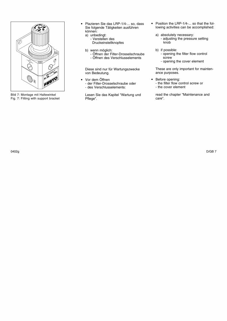
Bild 7: Montage mit HaltewinkelFig. 7: Fitting with support bracket
0402g D/GB 7
pneumatisch
• Stellen Sie sicher, daß folgende Punk-te eingehalten werden:- über den Anschluss p2 wird nicht
frei in die Umgebung abgeblasen(p2 ≠ 0 bar).Andernfalls steht an p2 aufgrundfehlender Rückkopplung der volleEingangsdruck an.
- ausschließlich Festo-Verschraubun-gen verwenden (z.B. Typ QS-...).
- Abdichtung der Verschraubungen mitDichtband nicht zulässig.Verschraubungen mit zu langerEinschraublänge oder Dichtband kön-nen die Querbohrung im Anschluss-gewinde des LRP-1/4-... abdeckenund dadurch die Funktionssicherheitgefährden.
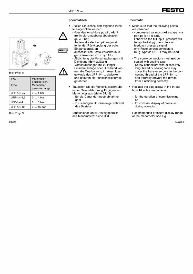
• Tauschen Sie die Verschlussschraubein der Gewindebohrung � gegen einManometer aus (siehe Bild 8)- für die Dauer der Inbetriebnahme
oder- zur ständigen Druckanzeige während
des Betriebs.
Empfohlener Druck-Anzeigebereichdes Manometers: siehe Bild 9.
Pneumatic
• Make sure that the following pointsare observed:- compressed air must not escape via
port p2 (p2 ≠ 0 bar).Otherwise the full input pressure willbe applied at p2 due to lack offeedback pressure signal.
- only Festo screws connectors(e. g. type as QS-...) may be used.
- The screw connectors must not besealed with sealing tape.Screw connectors with excessivelylong thread or sealing tape maycover the transverse bore in the con-necting thread of the LRP-1/4-...and threreby prevent the devicefrom functioning correctly.
• Replace the plug screw in the threadbore � with a manometer:
- for the duration of commissioningor
- for constant display of pressureduring operation.
Recommended pressure display rangeof the manometer see Fig. 9.
�
Bild 8/Fig. 8
Typ/
Type
Manometer-druckbereich/Manometerpressure range
LRP-1/4-0,7 0 ... 1 bar
LRP-1/4-2,5 0 ... 4 bar
LRP-1/4-4 0 ... 6 bar
LRP-1/4-10 0 ... 16 bar
Bild 9/Fig. 9
LRP-1/4-...
0402g D/GB 8
(P2 ≠ 0 bar)
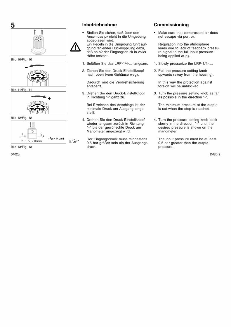
Inbetriebnahme
• Stellen Sie sicher, daß über denAnschluss p2 nicht in die Umgebungabgeblasen wird.Ein Regeln in die Umgebung führt auf-grund fehlender Rückkoppluing dazu,daß an p2 der Eingangsdruck in vollerHöhe ansteht.
1. Belüften Sie das LRP-1/4-... langsam.
2. Ziehen Sie den Druck-Einstellknopfnach oben (vom Gehäuse weg).
Dadurch wird die Verdrehsicherungentsperrt.
3. Drehen Sie den Druck-Einstellknopfin Richtung "-" ganz zu.
Bei Erreichen des Anschlags ist derminimale Druck am Ausgang einge-stellt.
4. Drehen Sie den Druck-Einstellknopfwieder langsam zurück in Richtung"+" bis der gewünschte Druck amManometer angezeigt wird.
Der Eingangsdruck muss mindestens0,5 bar größer sein als der Ausgangs-druck.
Commissioning
• Make sure that compressed air doesnot escape via port p2.
Regulation into the atmosphereleads due to lack of feedback pressu-re signal to the full input pressurebeing applied at p2.
1. Slowly pressurize the LRP-1/4-....
2. Pull the pressure setting knobupwards (away from the housing).
In this way the protection againsttorsion will be unblocked.
3. Turn the pressure setting knob as faras possible in the direction "-".
The minimum pressure at the outputis set when the stop is reached.
4. Turn the pressure setting knob backslowly in the direction "+" until thedesired pressure is shown on themanometer.
The input pressure must be at least0.5 bar greater than the outputpressure.
5
Bild 10/Fig. 10
Bild 12/Fig. 12
Bild 11/Fig. 11
P1 0,5 bar2P
P1 2P
>-
Bild 13/Fig. 13
0402g D/GB 9
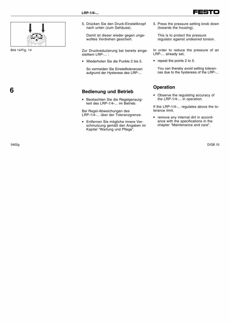
5. Drücken Sie den Druck-Einstellknopfnach unten (zum Gehäuse).
Damit ist dieser wieder gegen unge-wolltes Verdrehen gesichert.
Zur Druckreduzierung bei bereits einge-stelltem LRP-... :
• Wiederholen Sie die Punkte 2 bis 5.
So vermeiden Sie Einstelltoleranzenaufgrund der Hysterese des LRP-...
Bedienung und Betrieb
• Beobachten Sie die Regelgenauig-keit des LRP-1/4-... im Betrieb.
Bei Regel-Abweichungen desLRP-1/4-... über der Toleranzgrenze:
• Entfernen Sie mögliche innere Ver-schmutzung gemäß den Angaben imKapitel "Wartung und Pflege".
5. Press the pressure setting knob down(towards the housing).
This is to protect the pressureregulator against undesired torsion.
In order to reduce the pressure of anLRP-... already set,
• repeat the points 2 to 5.
You can thereby avoid setting toleran-ces due to the hysteresis of the LRP-...
Operation
• Observe the regulating accuracy ofthe LRP-1/4-... in operation.
If the LRP-1/4-... regulates above the to-lerance limit,
• remove any internal dirt in accord-ance with the specifications in thechapter "Maintenance and care".
Bild 14/Fig. 14
6
LRP-1/4-...
0402g D/GB 10
Wartung und Pflege
Bei äußerer Verschmutzung:
• Reinigen Sie bei Bedarf dasLRP-1/4-... außen mit einem weichenLappen.
Zulässiges Reinigungsmedium ist:Seifenlauge, max. 60 °C.
Bei innerer Verschmutzung:
1.Entlüften Sie das LRP-1/4-....
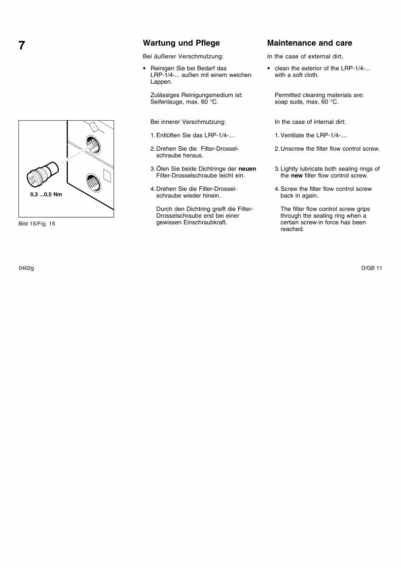
2.Drehen Sie die Filter-Drossel-schraube heraus.
3.Ölen Sie beide Dichtringe der neuenFilter-Drosselschraube leicht ein.
4.Drehen Sie die Filter-Drossel-schraube wieder hinein.
Durch den Dichtring greift die Filter-Drosselschraube erst bei einergewissen Einschraubkraft.
Maintenance and care
In the case of external dirt,
• clean the exterior of the LRP-1/4-...with a soft cloth.
Permitted cleaning materials are:soap suds, max. 60 °C.
In the case of internal dirt:
1.Ventilate the LRP-1/4-....
2.Unscrew the filter flow control screw.
3.Lightly lubricate both sealing rings ofthe new filter flow control screw.
4.Screw the filter flow control screwback in again.
The filter flow control screw gripsthrough the sealing ring when acertain screw-in force has beenreached.
0,3 ...0,5 Nm
Bild 15/Fig. 15
7
0402g D/GB 11
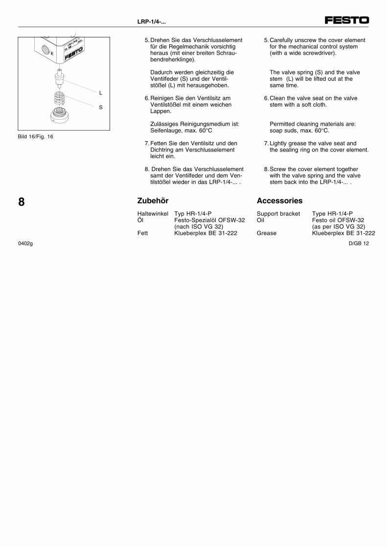
5.Drehen Sie das Verschlusselementfür die Regelmechanik vorsichtigheraus (mit einer breiten Schrau-bendreherklinge).
Dadurch werden gleichzeitig dieVentilfeder (S) und der Ventil-stößel (L) mit herausgehoben.
6.Reinigen Sie den Ventilsitz amVentilstößel mit einem weichenLappen.
Zulässiges Reinigungsmedium ist:Seifenlauge, max. 60°C
7.Fetten Sie den Ventilsitz und denDichtring am Verschlusselementleicht ein.
8. Drehen Sie das Verschlusselementsamt der Ventilfeder und dem Ven-tilstößel wieder in das LRP-1/4-... .
Zubehör
Haltewinkel Typ HR-1/4-PÖl Festo-Spezialöl OFSW-32
(nach ISO VG 32)Fett Klueberplex BE 31-222
5.Carefully unscrew the cover elementfor the mechanical control system(with a wide screwdriver).
The valve spring (S) and the valvestem (L) will be lifted out at thesame time.
6.Clean the valve seat on the valvestem with a soft cloth.
Permitted cleaning materials are:soap suds, max. 60°C.
7.Lightly grease the valve seat andthe sealing ring on the cover element.
8.Screw the cover element togetherwith the valve spring and the valvestem back into the LRP-1/4-... .
Accessories
Support bracket Type HR-1/4-POil Festo oil OFSW-32
(as per ISO VG 32)Grease Klueberplex BE 31-222
L
S
Bild 16/Fig. 16
8
LRP-1/4-...
0402g D/GB 12
Störungsbeseitigung9
Eliminating faults
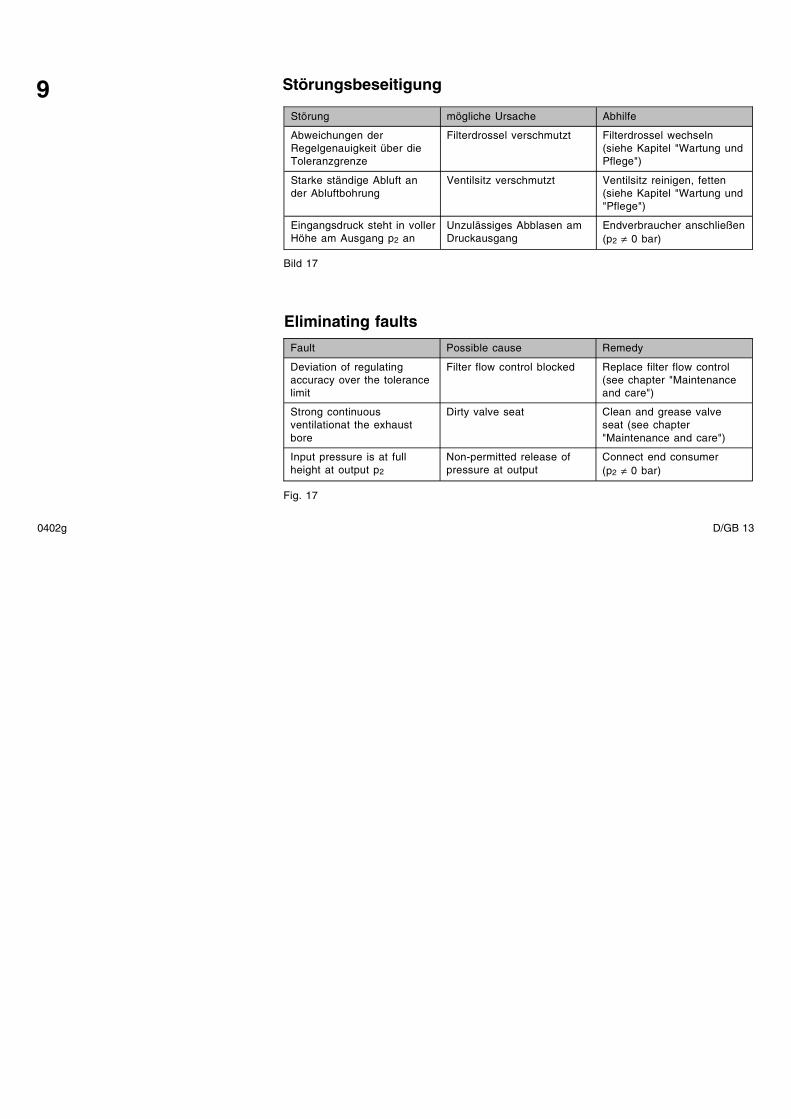
Störung mögliche Ursache Abhilfe
Abweichungen derRegelgenauigkeit über dieToleranzgrenze
Filterdrossel verschmutzt Filterdrossel wechseln(siehe Kapitel "Wartung undPflege")
Starke ständige Abluft ander Abluftbohrung
Ventilsitz verschmutzt Ventilsitz reinigen, fetten(siehe Kapitel "Wartung und"Pflege")
Eingangsdruck steht in vollerHöhe am Ausgang p2 an
Unzulässiges Abblasen amDruckausgang
Endverbraucher anschließen(p2 ≠ 0 bar)
Bild 17
Fault Possible cause Remedy
Deviation of regulatingaccuracy over the tolerancelimit
Filter flow control blocked Replace filter flow control(see chapter "Maintenanceand care")
Strong continuousventilationat the exhaustbore
Dirty valve seat Clean and grease valveseat (see chapter"Maintenance and care")
Input pressure is at fullheight at output p2
Non-permitted release ofpressure at output
Connect end consumer(p2 ≠ 0 bar)
Fig. 17
0402g D/GB 13
Technische Daten
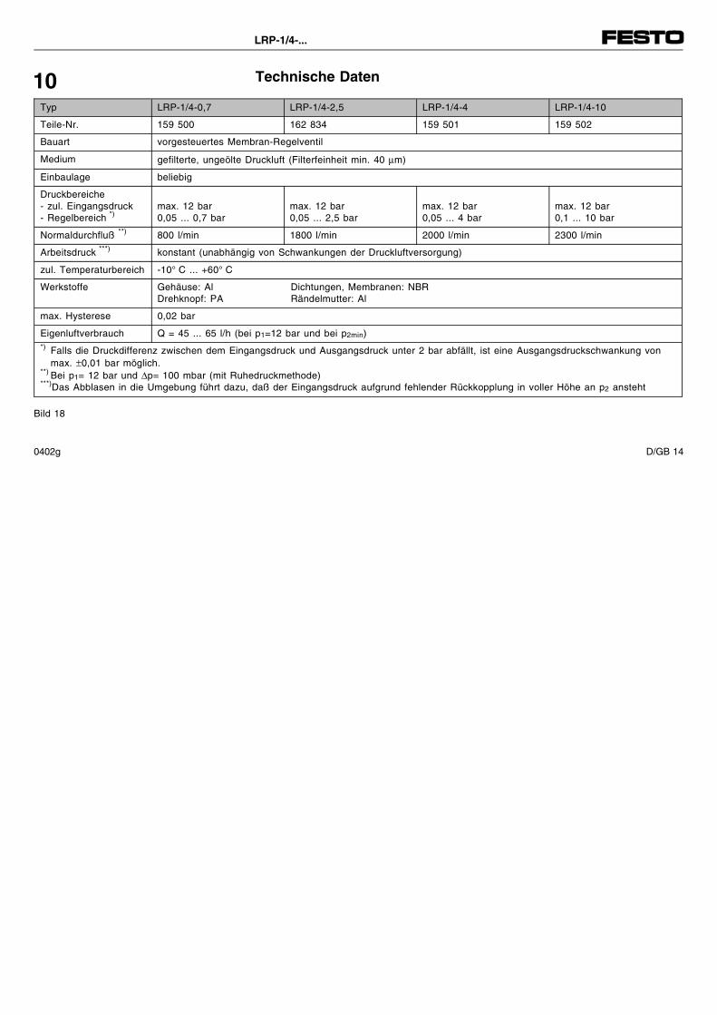
Typ LRP-1/4-0,7 LRP-1/4-2,5 LRP-1/4-4 LRP-1/4-10
Teile-Nr. 159 500 162 834 159 501 159 502
Bauart vorgesteuertes Membran-Regelventil
Medium gefilterte, ungeölte Druckluft (Filterfeinheit min. 40 µm)
Einbaulage beliebig
Druckbereiche- zul. Eingangsdruck- Regelbereich *)
max. 12 bar0,05 ... 0,7 bar
max. 12 bar0,05 ... 2,5 bar
max. 12 bar0,05 ... 4 bar
max. 12 bar0,1 ... 10 bar
Normaldurchfluß **) 800 l/min 1800 l/min 2000 l/min 2300 l/min
Arbeitsdruck ***) konstant (unabhängig von Schwankungen der Druckluftversorgung)
zul. Temperaturbereich -10° C ... +60° C
Werkstoffe Gehäuse: Al Dichtungen, Membranen: NBRDrehknopf: PA Rändelmutter: Al
max. Hysterese 0,02 bar
Eigenluftverbrauch Q = 45 ... 65 l/h (bei p1=12 bar und bei p2min)*) Falls die Druckdifferenz zwischen dem Eingangsdruck und Ausgangsdruck unter 2 bar abfällt, ist eine Ausgangsdruckschwankung von
max. ±0,01 bar möglich.**) Bei p1= 12 bar und ∆p= 100 mbar (mit Ruhedruckmethode)***)Das Abblasen in die Umgebung führt dazu, daß der Eingangsdruck aufgrund fehlender Rückkopplung in voller Höhe an p2 ansteht
Bild 18
10
LRP-1/4-...
0402g D/GB 14
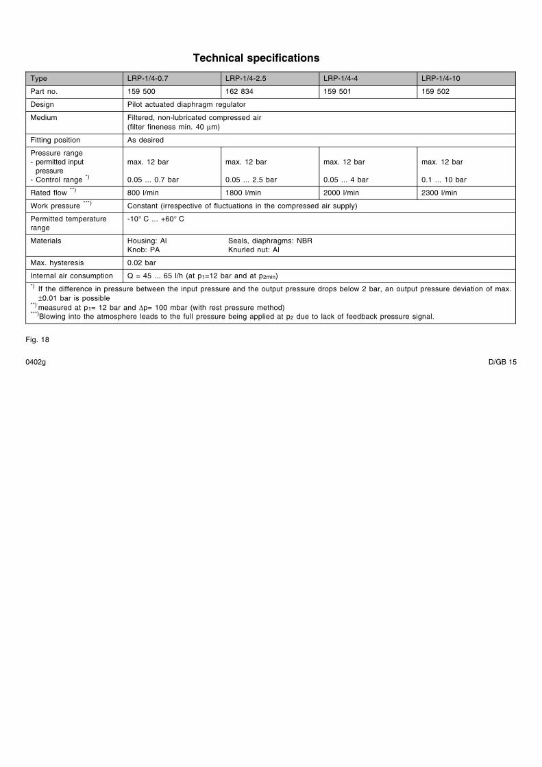
Technical specifications
Type LRP-1/4-0.7 LRP-1/4-2.5 LRP-1/4-4 LRP-1/4-10
Part no. 159 500 162 834 159 501 159 502
Design Pilot actuated diaphragm regulator
Medium Filtered, non-lubricated compressed air(filter fineness min. 40 µm)
Fitting position As desired
Pressure range- permitted input
pressure- Control range *)
max. 12 bar
0.05 ... 0.7 bar
max. 12 bar
0.05 ... 2.5 bar
max. 12 bar
0.05 ... 4 bar
max. 12 bar
0.1 ... 10 bar
Rated flow **) 800 l/min 1800 l/min 2000 l/min 2300 l/min
Work pressure ***) Constant (irrespective of fluctuations in the compressed air supply)
Permitted temperaturerange
-10° C ... +60° C
Materials Housing: Al Seals, diaphragms: NBRKnob: PA Knurled nut: Al
Max. hysteresis 0.02 bar
Internal air consumption Q = 45 ... 65 l/h (at p1=12 bar and at p2min)*) If the difference in pressure between the input pressure and the output pressure drops below 2 bar, an output pressure deviation of max.
±0.01 bar is possible**) measured at p1= 12 bar and ∆p= 100 mbar (with rest pressure method)***)Blowing into the atmosphere leads to the full pressure being applied at p2 due to lack of feedback pressure signal.
Fig. 18
0402g D/GB 15
PostfachD-73726 EsslingenPhone +49/711/347-0
Quelltext: deutschVersion: 0402g
Weitergabe sowie Vervielfätigung diesesDokuments, Verwertung und Mitteilungseines Inhalts verboten, soweit nichtausdrücklich gestattet. Zuwiderhandlun-gen verpflichten zu Schadenersatz. AlleRechte vorbehalten, insbesondere dasRecht, Patent-, Gebrauchsmuster- oderGeschmacksmusteranmeldungen durch-zuführen.
The copying, distribution and utilizationof this document as well as the commu-nication of its contents to others withoutexpressed authorization is prohibited.Offenders will be held liable for thepayment of damages. All rights reser-ved, in particular the right to carry outpatent, utility model or ornamental de-sign registrations.
0402g D/GB 16