Bedienungsanleitung Operation Manual · 2020-02-14 · Bedienungsanleitung Operation Manual...
4
Bedienungsanleitung Operation Manual Innovation, die bewegt! DCC MM AC ~ DC = SEL 5227 Relais, monostabil, 2 x 2UM, negativer Schaltimpuls Relay, monostable, 2 x 2UM, negative switching pulse 1. Wichtige Hinweise / Important information ........................................................ 2 2. Einleitung / Introduction ..................................................................................... 2 3. Anschluss / Connection ..................................................................................... 3 4. Technische Daten / Technical data .................................................................... 4
Transcript of Bedienungsanleitung Operation Manual · 2020-02-14 · Bedienungsanleitung Operation Manual...

BedienungsanleitungOperation Manual
Innovation, die bewegt!
DCC MM
AC~ DC=
SEL
5227
Relais, monostabil, 2 x 2UM, negativer SchaltimpulsRelay, monostable, 2 x 2UM, negative switching pulse
1. Wichtige Hinweise / Important information ........................................................ 22. Einleitung / Introduction ..................................................................................... 23. Anschluss / Connection ..................................................................................... 34. Technische Daten / Technical data .................................................................... 4

2
DE EN1. Wichtige HinweiseBitte lesen Sie vor der ersten Anwendung des Produktes bzw. dessen Einbau diese Bedienungsanleitung auf-merksam durch. Bewahren Sie diese auf, sie ist Teil des Produktes.
1.1 Sicherheitshinweise
Vorsicht:
Verletzungsgefahr!Für die Montage sind Werkzeuge nötig.Stromschlaggefahr! Die Anschlussdrähte niemals in eine Steckdose einfüh-ren! Verwendetes Versorgungsgerät (Transformator, Netzteil) regelmäßig auf Schäden überprüfen. Bei Schä-den am Versorgungsgerät dieses keinesfalls benutzen! Alle Anschluss- und Montagearbeiten nur bei abgeschal-teter Betriebsspannung durchführen! Ausschließlich nach VDE/EN gefertigte Modellbahn-transformatoren verwenden!Stromquellen unbedingt so absichern, dass es bei einem Kurzschluss nicht zum Kabelbrand kommen kann.
1.2 Das Produkt richtig verwendenDieses Produkt ist bestimmt:- Zum Einbau in Modelleisenbahnanlagen und Dioramen.- Zum Anschluss an den Doppel-Multiplexer Art. 52292.- Zum Anschluss an Viessmann Steuermodule (z. B. Art.
5214, 5208). - Zum Betrieb in trockenen Räumen.Jeder darüber hinausgehende Gebrauch gilt als nicht be-stimmungsgemäß. Für daraus resultierende Schäden haftet der Hersteller nicht.
1.3 Packungsinhalt überprüfen Kontrollieren Sie den Lieferumfang auf Vollständigkeit:- Zeitrelais- Beutel mit Steckern und Schrauben- Anleitung
2. EinführungDieses Modul besteht aus zwei voneinander unabhängigen monostabilen Relais mit je zwei Umschaltkontakten. Die Relais können mit Dauerstrom angesteuert werden obwohl sie keine Endabschaltung haben. Die Ansteuerung erfolgt durch negative Schaltsignale bzw. Dauerstrom, Wechselspannung oder Digitalstrom. Durch die interne Elektronik bleibt das Relais selbst bei Anschluss an Digital-stromkreise oder gepulste Signale geräuschlos. Es eignet sich dadurch z. B. auch, um Formsignale an Bau-steinen, die sonst nur Lichtsignale steuern, anzuschließen, z. B. Art. 5208 und Art. 5214. Das Relais ist besonders für die Fahrstrombeeinflussung durch den Doppel-Multiplexer Art. 52292 geeignet.
1. Important informationPlease read this manual completely and attentively before using the product for the first time. Keep this manual. It is part of the product.
1.1 Safety instructions
Caution:
Risk of injury!Tools are required for installation.Electrical hazard!Never put the connecting wires into a power socket! Regularly examine the transformer for damage. In case of any damage, do not use the transformer.Make sure that the power supply is switched off when you mount the device and connect the cables!Only use VDE/EN tested special model train transform-ers for the power supply!The power sources must be protected to avoid the risk of burning cables.
1.2 Using the product for its correct purpose
This product is intended:- For installation in model train layouts and dioramas.- For connection to the double multiplexer item 52292.- For connection to other Viessmann modules (e. g. items
5214, 5208).- For operation in dry rooms only. Using the product for any other purpose is not approved and is considered inappropriate. The manufacturer is not responsible for any damage resulting from the improper use of this product.
1.3 Checking the package contents
Check the contents of the package for completeness:- Relay- Bag with plugs and screws- Manual
2. IntroductionThis module consists of two separately controlled mon-ostable relays with two change-over contacts each. The relays may be supplied with continuous current even though they have no end-of-position contacts. Control is facilitated by negative switching signals or continuous cur-rent, AC or digital formats. Due to the internal circuitry the module remains silent even when it is powered by digital or pulsed signals. Therefore, it is also suitable for driving semaphore signals powered by modules, which generally are only suitable for daylight signals, such as items 5214 or 5208. This module is particularly well suited for switching track current in con-junction with the double multiplexer item 52292.
3
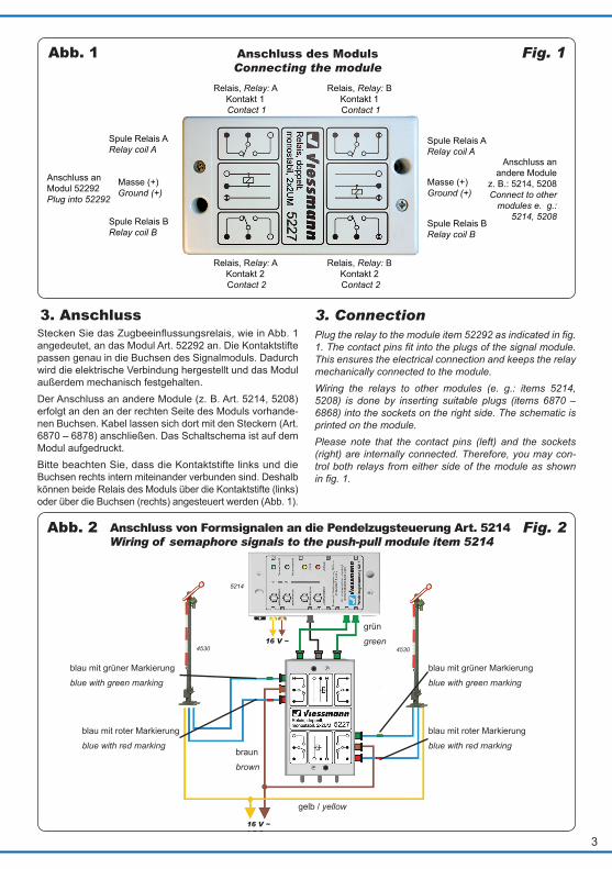
Relais, Relay: A Kontakt 1 Contact 1
Spule Relais A Relay coil A
Masse (+) Ground (+)
Anschluss an Modul 52292 Plug into 52292
Spule Relais B Relay coil B
Spule Relais A Relay coil A
Spule Relais B Relay coil B
Masse (+) Ground (+)
Anschluss an andere Module
z. B.: 5214, 5208 Connect to other
modules e. g.: 5214, 5208
Relais, Relay: B Kontakt 1 Contact 1
Relais, Relay: A Kontakt 2 Contact 2
Relais, Relay: B Kontakt 2 Contact 2
Fig. 1Abb. 1
3. AnschlussStecken Sie das Zugbeeinflussungsrelais, wie in Abb. 1 angedeutet, an das Modul Art. 52292 an. Die Kontaktstifte passen genau in die Buchsen des Signalmoduls. Dadurch wird die elektrische Verbindung hergestellt und das Modul außerdem mechanisch festgehalten. Der Anschluss an andere Module (z. B. Art. 5214, 5208) erfolgt an den an der rechten Seite des Moduls vorhande-nen Buchsen. Kabel lassen sich dort mit den Steckern (Art. 6870 – 6878) anschließen. Das Schaltschema ist auf dem Modul aufgedruckt. Bitte beachten Sie, dass die Kontaktstifte links und die Buchsen rechts intern miteinander verbunden sind. Deshalb können beide Relais des Moduls über die Kontaktstifte (links) oder über die Buchsen (rechts) angesteuert werden (Abb. 1).
3. Connection Plug the relay to the module item 52292 as indicated in fig. 1. The contact pins fit into the plugs of the signal module. This ensures the electrical connection and keeps the relay mechanically connected to the module. Wiring the relays to other modules (e. g.: items 5214, 5208) is done by inserting suitable plugs (items 6870 – 6868) into the sockets on the right side. The schematic is printed on the module. Please note that the contact pins (left) and the sockets (right) are internally connected. Therefore, you may con-trol both relays from either side of the module as shown in fig. 1.
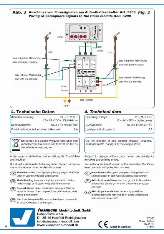
5214
4530 4530
16 V ~
16 V ~
Abb. 2 Fig. 2Anschluss von Formsignalen an die Pendelzugsteuerung Art. 5214Wiring of semaphore signals to the push-pull module item 5214
Anschluss des Moduls Connecting the module
blau mit grüner Markierung
blue with green marking
blau mit grüner Markierung
blue with green marking
blau mit roter Markierung
blue with red marking
blau mit roter Markierung
blue with red marking
gelb / yellow
braun
brown
grün
green
Modellbauartikel, kein Spielzeug! Nicht geeignet für Kinder unter 14 Jahren! Anleitung aufbewahren!
Model building item, not a toy! Not suitable for children under the age of 14 years! Keep these instructions!
Ce n’est pas un jouet. Ne convient pas aux enfants de moins de 14 ans ! C’est un produit décor! Conservez cette notice d’instructions!
Não é um brinquedo!Não aconselhável para menores de 14 anos. Conservar a embalagem.
Modelbouwartikel, geen speelgoed! Niet geschikt voor kinderen onder 14 jaar! Gebruiksaanwijzing bewaren!
Articolo di modellismo, non è un giocattolo! Non adatto a bambini al di sotto dei 14 anni! Conservare instruzioni per l’uso!
Artículo para modelismo ¡No es un juguete! No recomendado para menores de 14 años! Conserva las instrucciones de servicio!
DE
EN
FR
NL
IT
ES
PT
Made in Europe
Viessmann Modelltechnik GmbH Bahnhofstraße 2a D - 35116 Hatzfeld-Reddighauseninfo@viessmann-modell.comwww.viessmann-modell.de4
16 V ~
4530 4530
Fig. 3Abb. 3 Anschluss von Formsignalen am Aufenthaltsschalter Art. 5208Wiring of semaphore signals to the timer module item 5208
5208
Änderungen vorbehalten. Keine Haftung für Druckfehler und Irrtümer.Die aktuelle Version der Anleitung finden Sie auf der Viess-mann Homepage unter der Artikelnummer.
Subject to change without prior notice. No liability for mistakes and printing errors.You will find the latest version of the manual on the Viess-mann website using the item number.
Entsorgen Sie dieses Produkt nicht über den (unsortierten) Hausmüll, sondern führen Sie es der Wiederverwertung zu.
Do not dispose of this product through (unsorted) domestic waste, supply it to recycling instead.
blau mit grüner Markierung
blue with green marking
blau mit grüner Markierung
blue with green marking
blau mit roter Markierung
blue with red marking
blau mit roter Markierung
blue with red marking
gelb / yellow
braun
brown
grün
green
4. Technical dataOperating voltage: 10 – 16 V AC~ 12 – 24 V DC= / digital powerCurrent draw: ca. 2 x 14 mA at 16VLoad per set of contacts: 2 A
4. Technische DatenBetriebsspannung: 10 – 16 V AC~ 12 – 24 V DC= / DigitalstromStromaufnahme: ca. 2 x 14 mA bei 16VKontaktbelastbarkeit je Umschaltkontakt: 2 A
87640 Stand 02/sw
07/2019 Ho/Kf