Betriebsanleitung - wekonn.de · 3 Informationen zur Sicherheit DE FloCo-Top-1K 2 Informationen zur...
162
Version: 12.2016.0 ID: 900.000.0287 Lindenstraße 20 74363 Güglingen Telefon +49 7135-102-0 Service +49 7135-102-211 Telefax +49 7135-102-147 [email protected] www.afriso.com Copyright 2016 AFRISO-EURO-INDEX GmbH. Alle Rechte vorbehalten. BRL A Teil 1 EN 12514-2 in Verbindung mit einem PA-Schlauch 4 x 1 mm DE Betriebsanleitung Automatischer Heizölentlüfter mit integriertem Filter FloCo-Top-1K
Transcript of Betriebsanleitung - wekonn.de · 3 Informationen zur Sicherheit DE FloCo-Top-1K 2 Informationen zur...

Version: 12.2016.0ID: 900.000.0287
Lindenstraße 2074363 Güglingen
Telefon +49 7135-102-0Service +49 7135-102-211Telefax +49 7135-102-147
Copyright 2016 AFRISO-EURO-INDEX GmbH. Alle Rechte vorbehalten.
BRL A Teil 1EN 12514-2
in Verbindung mit einemPA-Schlauch 4 x 1 mm
DE
Betriebsanleitung
Automatischer Heizölentlüftermit integriertem Filter
FloCo-Top-1K

2
Über diese Betriebsanleitung DE
FloCo-Top-1K
1 Über diese BetriebsanleitungDiese Betriebsanleitung beschreibt den automatischen Heizölentlüfter mitintegriertem Filter „FloCo-Top-1K“ (im folgenden auch „Produkt“). DieseBetriebsanleitung ist Teil des Produkts.
• Sie dürfen das Produkt erst benutzen, wenn Sie die Betriebsanleitungvollständig gelesen und verstanden haben.
• Stellen Sie sicher, dass die Betriebsanleitung für alle Arbeiten an und mitdem Produkt jederzeit verfügbar ist.
• Geben Sie die Betriebsanleitung und alle zum Produkt gehörendenUnterlagen an alle Benutzer des Produkts weiter.
• Wenn Sie der Meinung sind, dass die Betriebsanleitung Fehler, Wider-sprüche oder Unklarheiten enthält, wenden Sie sich vor Benutzung desProdukts an den Hersteller.
Diese Betriebsanleitung ist urheberrechtlich geschützt und darf ausschließ-lich im rechtlich zulässigen Rahmen verwendet werden. Änderungen vorbe-halten.
Für Schäden und Folgeschäden, die durch Nichtbeachtung dieser Betriebs-anleitung sowie Nichtbeachten der am Einsatzort des Produkts geltendenVorschriften, Bestimmungen und Normen entstehen, übernimmt der Herstel-ler keinerlei Haftung oder Gewährleistung.
3
Informationen zur Sicherheit DE
FloCo-Top-1K
2 Informationen zur Sicherheit
2.1 Warnhinweise und GefahrenklassenIn dieser Betriebsanleitung finden Sie Warnhinweise, die auf potenzielleGefahren und Risiken aufmerksam machen. Zusätzlich zu den Anweisungenin dieser Betriebsanleitung müssen Sie alle am Einsatzort des Produktesgeltenden Bestimmungen, Normen und Sicherheitsvorschriften beachten.Stellen Sie vor Verwendung des Produktes sicher, dass Ihnen alle Bestim-mungen, Normen und Sicherheitsvorschriften bekannt sind und dass siebefolgt werden.
Warnhinweise sind in dieser Betriebsanleitung mit Warnsymbolen und Sig-nalwörtern gekennzeichnet. Abhängig von der Schwere einer Gefährdungs-situation werden Warnhinweise in unterschiedliche Gefahrenklassen unter-teilt.
HINWEISHINWEIS macht auf eine möglicherweise gefährliche Situation aufmerksam, diebei Nichtbeachtung Sachschäden zur Folge haben kann.
4
Informationen zur Sicherheit DE
FloCo-Top-1K
2.2 Bestimmungsgemäße VerwendungDieses Produkt eignet sich ausschließlich für den Einsatz in Einstrangsyste-men mit Rücklaufzuführung zur kontinuierlichen Entlüftung folgender Flüs-sigkeiten in Ölfeuerungsanlagen:
• Heizöl EL nach DIN 51603-1- mit 0-20 % Fettsäure-Methylester (FAME) nach EN 14214
• Dieselkraftstoff nach EN 590- mit 0-20 % Fettsäure-Methylester (FAME) nach EN 14214
Eine andere Verwendung ist nicht bestimmungsgemäß und verursachtGefahren.
Stellen Sie vor Verwendung des Produkts sicher, dass das Produkt für dievon Ihnen vorgesehene Verwendung geeignet ist. Berücksichtigen Sie dabeimindestens folgendes:
• Alle am Einsatzort geltenden Bestimmungen, Normen und Sicherheits-vorschriften
• Alle für das Produkt spezifizierten Bedingungen und Daten
• Die Bedingungen der von Ihnen vorgesehenen Anwendung
Führen Sie darüber hinaus eine Risikobeurteilung in Bezug auf die konkrete,von Ihnen vorgesehene Anwendung nach einem anerkannten Verfahrendurch und treffen Sie entsprechende dem Ergebnis alle erforderlichenSicherheitsmaßnahmen. Berücksichtigen Sie dabei auch die möglichen Fol-gen eines Einbaus oder einer Integration des Produkts in ein System oder ineine Anlage.
Führen Sie bei der Verwendung des Produkts alle Arbeiten ausschließlichunter den in der Betriebsanleitung und auf dem Typenschild spezifiziertenBedingungen und innerhalb der spezifizierten technischen Daten und inÜbereinstimmung mit allen am Einsatzort geltenden Bestimmungen, Nor-men und Sicherheitsvorschriften durch.
5
Informationen zur Sicherheit DE
FloCo-Top-1K
2.3 Vorhersehbare FehlanwendungDas Produkt darf insbesondere in folgenden Fällen und für folgende Zweckenicht angewendet werden:
• Einsatz in unverdünnten Additiven, Alkoholen und Säuren
• Einsatz in Druckversorgungsanlagen ohne entsprechende Schutzvorkeh-rungen
2.4 Qualifikation des PersonalsArbeiten an und mit diesem Produkt dürfen nur von Fachkräften vorgenom-men werden, die den Inhalt dieser Betriebsanleitung und alle zum Produktgehörenden Unterlagen kennen und verstehen.
Die Fachkräfte müssen aufgrund ihrer fachlichen Ausbildung, Kenntnisseund Erfahrungen in der Lage sein, mögliche Gefährdungen vorherzusehenund zu erkennen, die durch den Einsatz des Produkts entstehen können.
Den Fachkräften müssen alle geltenden Bestimmungen, Normen undSicherheitsvorschriften, die bei Arbeiten an und mit dem Produkt beachtetwerden müssen, bekannt sein.
2.5 Persönliche SchutzausrüstungVerwenden Sie immer die erforderliche persönliche Schutzausrüstung.Berücksichtigen Sie bei Arbeiten an und mit dem Produkt auch, dass am Ein-satzort Gefährdungen auftreten können, die nicht direkt vom Produkt ausge-hen.
2.6 Veränderungen am ProduktFühren Sie ausschließlich solche Arbeiten an und mit dem Produkt durch, diein dieser Betriebsanleitung beschrieben sind. Nehmen Sie keine Verände-rungen vor, die in dieser Betriebsanleitung nicht beschrieben sind.
6
Transport und Lagerung DE
FloCo-Top-1K
3 Transport und LagerungDas Produkt kann durch unsachgemäßen Transport und Lagerung beschä-digt werden.
HINWEISBESCHÄDIGUNG DES PRODUKTS• Stellen Sie sicher, dass während des Transports und der Lagerung des Pro-
dukts die spezifizierten Umgebungsbedingungen eingehalten werden.• Benutzen Sie für den Transport die Originalverpackung.• Lagern Sie das Produkt nur in trockener, sauberer Umgebung.• Stellen Sie sicher, dass das Produkt bei Transport und Lagerung stoßge-
schützt ist.
Nichtbeachtung dieser Anweisungen kann zu Sachschäden führen.
7
Produktbeschreibung DE
FloCo-Top-1K
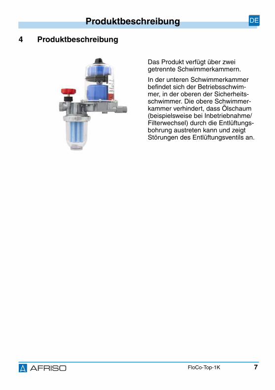
4 Produktbeschreibung
Das Produkt verfügt über zweigetrennte Schwimmerkammern.
In der unteren Schwimmerkammerbefindet sich der Betriebsschwim-mer, in der oberen der Sicherheits-schwimmer. Die obere Schwimmer-kammer verhindert, dass Ölschaum(beispielsweise bei Inbetriebnahme/Filterwechsel) durch die Entlüftungs-bohrung austreten kann und zeigtStörungen des Entlüftungsventils an.

8
Produktbeschreibung DE
FloCo-Top-1K
4.1 FunktionDie Brennerpumpe saugt durch den Filter über das im Gehäuse eingebauteRückschlagventil das Heizöl vom Tank an und fördert es zur Düse. Die überdie Düsenleistung hinausgehende Ölmenge wird von der Pumpe über denAnschlussstutzen der Rücklaufleitung in die Schwimmerkammer gepumpt.Hier erfolgt unter allmählichem Anstieg des Flüssigkeitspegels die Entlüftungdurch das Entlüftungsventil.
Bei einem Ölniveau von circa 20-30 mm über der Bodenfläche beginnt derBetriebsschwimmer aufzutreiben und steuert damit das Bypassventil, dasdas entlüftete Rücklauföl der Saugleitung zuführt. Dadurch wird nur dieÖlmenge über den Filter aus dem Tank angesaugt, die tatsächlich für die Ver-brennung benötigt wird. Die Filterstandzeit wird dadurch stark erhöht.
Der zur Pumpe fließende Volumenstrom besteht zum größten Teil aus entlüf-tetem Heizöl und in kleineren Teilen aus Öl vom Tank, das noch Luftanteileenthält.
4.2 Zulassungsdokumente, Bescheinigungen, ErklärungenDas Produkt ist vom TÜV geprüft (Bericht Nummer S 133 2013 E2).
A. QTank = QDüse
B. QRücklauf
C. QVorlauf
D. QDüse
AD
B
C
9
Produktbeschreibung DE
FloCo-Top-1K
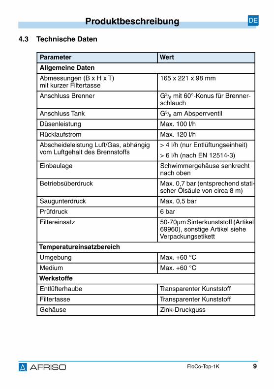
4.3 Technische Daten
Parameter Wert
Allgemeine Daten
Abmessungen (B x H x T)mit kurzer Filtertasse
165 x 221 x 98 mm
Anschluss Brenner G3/8 mit 60°-Konus für Brenner-schlauch
Anschluss Tank G3/8 am Absperrventil
Düsenleistung Max. 100 l/h
Rücklaufstrom Max. 120 l/h
Abscheideleistung Luft/Gas, abhängigvom Luftgehalt des Brennstoffs
> 4 l/h (nur Entlüftungseinheit)
> 6 l/h (nach EN 12514-3)
Einbaulage Schwimmergehäuse senkrechtnach oben
Betriebsüberdruck Max. 0,7 bar (entsprechend stati-scher Ölsäule von circa 8 m)
Saugunterdruck Max. 0,5 bar
Prüfdruck 6 bar
Filtereinsatz 50-70µm Sinterkunststoff (Artikel69960), sonstige Artikel sieheVerpackungsetikett
Temperatureinsatzbereich
Umgebung Max. +60 °C
Medium Max. +60 °C
Werkstoffe
Entlüfterhaube Transparenter Kunststoff
Filtertasse Transparenter Kunststoff
Gehäuse Zink-Druckguss
10
Montage DE
FloCo-Top-1K
5 MontageDas Produkt wird vor dem Brenner installiert. Die Armatur darf über oderunter dem Tankspiegel eingebaut werden.
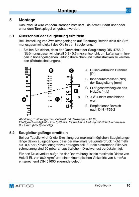
5.1 Querschnitt der Saugleitung ermittelnBei Umstellung von Zweistranganlagen auf Einstrang-Betrieb sinkt die Strö-mungsgeschwindigkeit des Öls in der Saugleitung.
1. Stellen Sie sicher, dass der Querschnitt der Saugleitung DIN 4755-2(Strömungsgeschwindigkeit 0,2 - 0,5 m/s) entspricht, um Luftansammlun-gen in höher gelegenen Leitungsbereichen und Gefällstrecken zu vermei-den (Störabschaltungen).
5.2 Saugleitungslänge ermittelnBei der Tabelle wird für die Ermittlung der maximal möglichen Saugleitungs-länge davon ausgegangen, dass der maximale Saugunterdruck nicht mehrals -0,4 bar (Kavitationsgrenze) betragen soll. Für die eintretende Filterver-schmutzung sind 50 mbar an zusätzlichem Druckverlust berücksichtigt.
Für den Druckverlust aufgrund der Rohrreibung, ist die maximale Dichte vonHeizöl EL von 860 kg/m3 und einer kinematischen Viskosität von 6 mm2/sentsprechend DIN 51603 zugrunde gelegt.
A. Düsenverbrauch Brenner[l/h]
B. Innendurchmesser (NW)der Saugleitung [mm]
C. Fließgeschwindigkeit desHeizöls [m/s]
D. < Ø 4 nicht empfehlens-wert
E. Empfohlener Bereichnach DIN 4755-2
Abbildung 1: Nomogramm; Beispiel: Fördermenge = 20 l/h,Fließgeschwindigkeit = Ø ~ 0,23 m/s. Es wird eine Leitung mit Rohrdurchmesser8 x 1 mm (NW 6) benötigt.
A
CB
D
E
11
Montage DE
FloCo-Top-1K
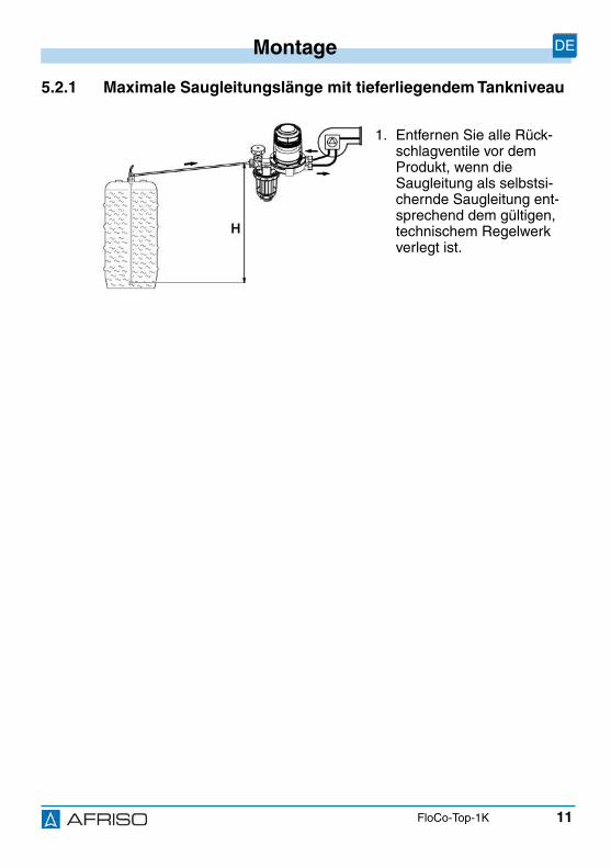
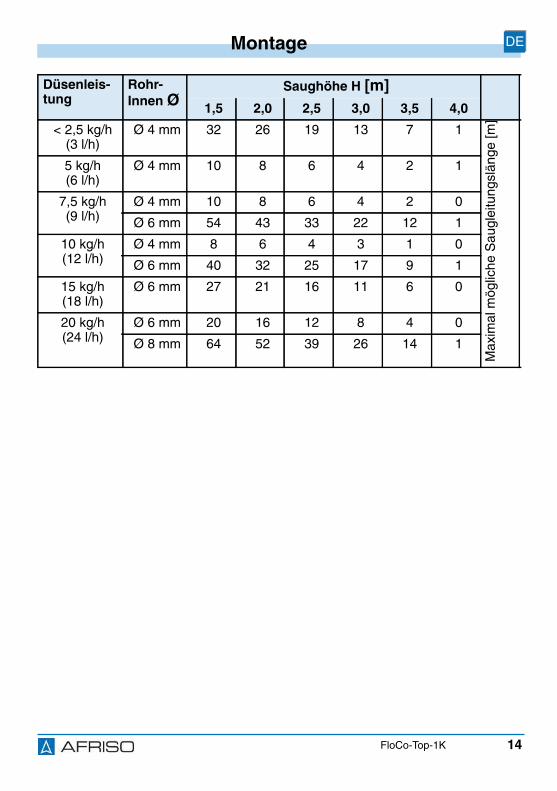
5.2.1 Maximale Saugleitungslänge mit tieferliegendem Tankniveau
1. Entfernen Sie alle Rück-schlagventile vor demProdukt, wenn dieSaugleitung als selbstsi-chernde Saugleitung ent-sprechend dem gültigen,technischem Regelwerkverlegt ist.
12
Montage DE
FloCo-Top-1K
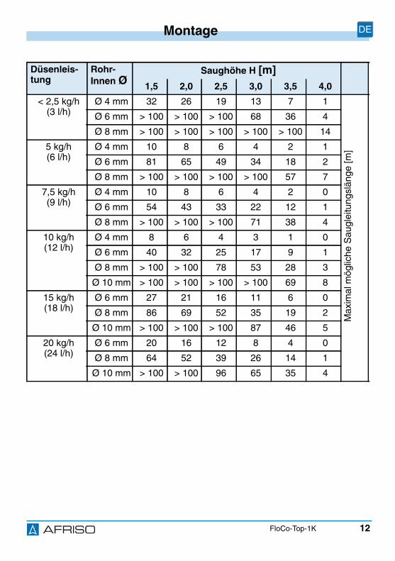
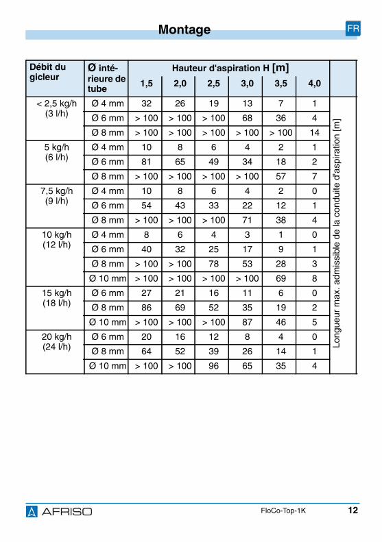
Düsenleis-tung
Rohr-Innen Ø
Saughöhe H [m]1,5 2,0 2,5 3,0 3,5 4,0
< 2,5 kg/h(3 l/h)
Ø 4 mm 32 26 19 13 7 1
Max
imal
mög
liche
Sau
glei
tung
slän
ge[m
]
Ø 6 mm > 100 > 100 > 100 68 36 4
Ø 8 mm > 100 > 100 > 100 > 100 > 100 14
5 kg/h(6 l/h)
Ø 4 mm 10 8 6 4 2 1
Ø 6 mm 81 65 49 34 18 2
Ø 8 mm > 100 > 100 > 100 > 100 57 7
7,5 kg/h(9 l/h)
Ø 4 mm 10 8 6 4 2 0
Ø 6 mm 54 43 33 22 12 1
Ø 8 mm > 100 > 100 > 100 71 38 4
10 kg/h(12 l/h)
Ø 4 mm 8 6 4 3 1 0
Ø 6 mm 40 32 25 17 9 1
Ø 8 mm > 100 > 100 78 53 28 3
Ø 10 mm > 100 > 100 > 100 > 100 69 8
15 kg/h(18 l/h)
Ø 6 mm 27 21 16 11 6 0
Ø 8 mm 86 69 52 35 19 2
Ø 10 mm > 100 > 100 > 100 87 46 5
20 kg/h(24 l/h)
Ø 6 mm 20 16 12 8 4 0
Ø 8 mm 64 52 39 26 14 1
Ø 10 mm > 100 > 100 96 65 35 4
13
Montage DE
FloCo-Top-1K
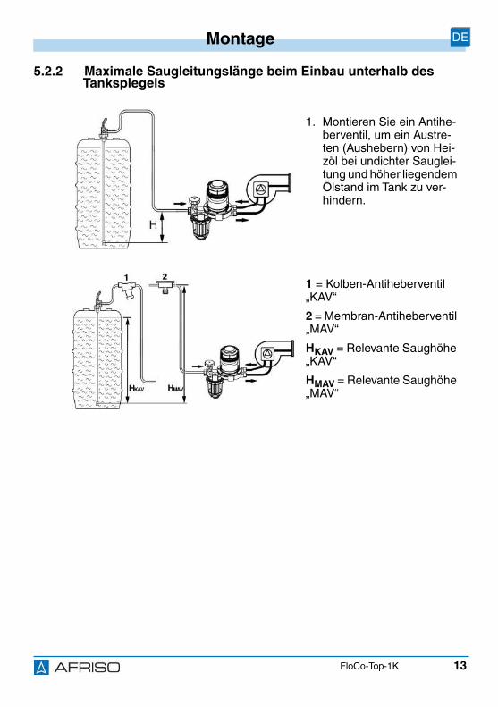
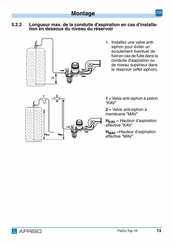
5.2.2 Maximale Saugleitungslänge beim Einbau unterhalb desTankspiegels
1. Montieren Sie ein Antihe-berventil, um ein Austre-ten (Aushebern) von Hei-zöl bei undichter Sauglei-tung und höher liegendemÖlstand im Tank zu ver-hindern.
1 = Kolben-Antiheberventil„KAV“
2 = Membran-Antiheberventil„MAV“
HKAV = Relevante Saughöhe„KAV“
HMAV = Relevante Saughöhe„MAV“
14
Montage DE
FloCo-Top-1K
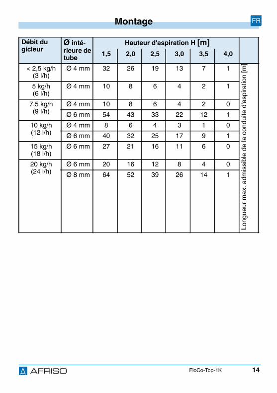
Düsenleis-tung
Rohr-Innen Ø
Saughöhe H [m]1,5 2,0 2,5 3,0 3,5 4,0
< 2,5 kg/h(3 l/h)
Ø 4 mm 32 26 19 13 7 1
Max
imal
mög
liche
Sau
glei
tung
slän
ge[m
]
5 kg/h(6 l/h)
Ø 4 mm 10 8 6 4 2 1
7,5 kg/h(9 l/h)
Ø 4 mm 10 8 6 4 2 0
Ø 6 mm 54 43 33 22 12 1
10 kg/h(12 l/h)
Ø 4 mm 8 6 4 3 1 0
Ø 6 mm 40 32 25 17 9 1
15 kg/h(18 l/h)
Ø 6 mm 27 21 16 11 6 0
20 kg/h(24 l/h)
Ø 6 mm 20 16 12 8 4 0
Ø 8 mm 64 52 39 26 14 1
15
Montage DE
FloCo-Top-1K
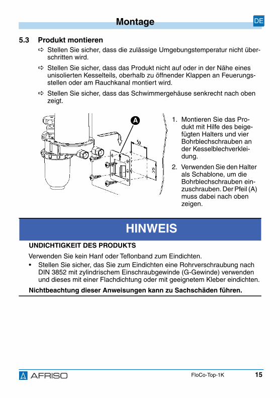
5.3 Produkt montieren Stellen Sie sicher, dass die zulässige Umgebungstemperatur nicht über-
schritten wird.
Stellen Sie sicher, dass das Produkt nicht auf oder in der Nähe einesunisolierten Kesselteils, oberhalb zu öffnender Klappen an Feuerungs-stellen oder am Rauchkanal montiert wird.
Stellen Sie sicher, dass das Schwimmergehäuse senkrecht nach obenzeigt.
1. Montieren Sie das Pro-dukt mit Hilfe des beige-fügten Halters und vierBohrblechschrauben ander Kesselblechverklei-dung.
2. Verwenden Sie den Halterals Schablone, um dieBohrblechschrauben ein-zuschrauben. Der Pfeil (A)muss dabei nach obenzeigen.
HINWEISUNDICHTIGKEIT DES PRODUKTS
Verwenden Sie kein Hanf oder Teflonband zum Eindichten.• Stellen Sie sicher, das Sie zum Eindichten eine Rohrverschraubung nach
DIN 3852 mit zylindrischem Einschraubgewinde (G-Gewinde) verwendenund dieses mit einer Flachdichtung oder mit geeignetem Kleber eindichten.
Nichtbeachtung dieser Anweisungen kann zu Sachschäden führen.
A
16
Montage DE
FloCo-Top-1K
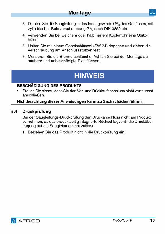
3. Dichten Sie die Saugleitung in das Innengewinde G3/8 des Gehäuses, mitzylindrischer Rohrverschraubung G3/8 nach DIN 3852 ein.
4. Verwenden Sie bei weichem oder halb hartem Kupferrohr eine Stütz-hülse.
5. Halten Sie mit einem Gabelschlüssel (SW 24) dagegen und ziehen dieVerschraubung am Anschlussstutzen fest.
6. Montieren Sie die Brennerschläuche. Achten Sie bei der Montage aufsaubere und unbeschädigte Dichtflächen.
5.4 DruckprüfungBei der Saugleitungs-Druckprüfung den Druckanschluss nicht am Produktvornehmen, da das produktseitig integrierte Rückschlagventil die Drucküber-tragung auf die Saugleitung nicht zulässt.
1. Beziehen Sie das Produkt nicht in die Druckprüfung ein.
HINWEISBESCHÄDIGUNG DES PRODUKTS• Stellen Sie sicher, dass Sie den Vor- und Rücklaufanschluss nicht vertauscht
anschließen.
Nichtbeachtung dieser Anweisungen kann zu Sachschäden führen.
17
Montage DE
FloCo-Top-1K
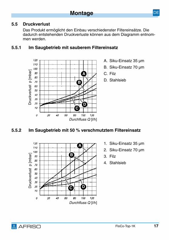
5.5 DruckverlustDas Produkt ermöglicht den Einbau verschiedenster Filtereinsätze. Diedadurch entstehenden Druckverluste können aus dem Diagramm entnom-men werden.
5.5.1 Im Saugbetrieb mit sauberem Filtereinsatz
5.5.2 Im Saugbetrieb mit 50 % verschmutztem Filtereinsatz
A. Siku-Einsatz 35 µm
B. Siku-Einsatz 70 µm
C. Filz
D. Stahlsieb
1. Siku-Einsatz 35 µm
2. Siku-Einsatz 70 µm
3. Filz
4. Stahlsieb
Durchfluss Q [l/h]
Dru
ckve
rlust
p[m
bar]
A
B
DC
Durchfluss Q [l/h]
Dru
ckve
rlust
p[m
bar]
A
B
DC
18
Montage DE
FloCo-Top-1K
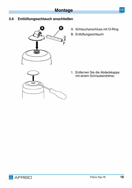
5.6 Entlüftungsschlauch anschließen
A. Schlauchanschluss mit O-Ring
B. Entlüftungsschlauch
1. Entfernen Sie die Abdeckkappemit einem Schraubendreher.
BA

19
Montage DE
FloCo-Top-1K
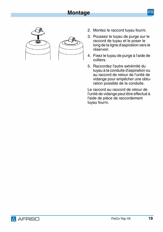
2. Montieren Sie den beigelegtenSchlauchanschluss.
3. Schieben Sie den Entlüftungs-schlauch auf den Schlauchan-schluss auf und führen ihn ent-lang der Saugleitung zum Tankzurück.
4. Fixieren Sie den Entlüftungs-schlauch mit Kabelbindern.
5. Bringen Sie das andere Ende desEntlüftungsschlauchs an der Ent-lüftungsleitung oder am Rücklau-fanschluss der Entnahmearmaturdes Tanks an, um einen eventuel-len Leitungsverschluss vorzubeu-gen.
Der Anschluss an den Rücklaufan-schluss der Entnahmearmatur kannmit der beiliegenden Schlauchtüllevorgenommen werden.
20
Betrieb DE
FloCo-Top-1K
6 Betrieb
6.1 Ölstand im SchwimmergehäuseDer Flüssigkeitsstand stellt sich in Abhängigkeit von den anlagebedingtenBetriebsbedingungen ein und liegt im Saugbetrieb bei circa 20-50 mm. Beihöher liegendem Ölspiegel kann es bei einer dicht verlegten Saugleitung zueinem vollständig mit Öl gefüllten Schwimmergehäuse kommen. Verursachtwird dies durch die Absorption der Luft vom Heizöl. Dieser Effekt bewirkt imLaufe der Zeit einen Abbau des Luftpolsters. Ändern sich die Betriebsbedin-gungen beispielsweise durch sinkenden Flüssigkeitsstand im Tank, so bildetsich wieder ein Luftpolster im Schwimmergehäuse.
6.2 DruckbetriebDa es im Druckbetrieb mit einer Ölförderpumpe zu keinen Saugausgasun-gen kommt, ist es nicht sinnvoll hier das Produkt einzusetzen. Im Druckbe-trieb sollte ein Einstrangfilter mit Rücklaufzuführung eingesetzt werden.Wenn anlagenbedingt ein Heizölentlüfter benötigt wird, kann ein„Flow-Control 3/K HT“ mit vorgeschaltetem Filter und Messing-Filtertasseoder Wechselfilterkartusche verwendet werden.
Stellen Sie sicher, dass Sie für diese Anwendung geeignete Vorkehrun-gen treffen, die auch im Störfall (defekter Druckminderer) ein Überschrei-ten des maximal zulässigen Vordrucks von 0,7 bar verhindern (beispiels-weise über ein Überströmventil, Druckschalter).
Stellen Sie sicher, dass Sie unterhalb der Brennerschläuche und desÖlentlüfters eine Auffangwanne aufstellen, über welche ein möglicherÖlaustritt detektiert wird, sowie eine Abschaltung des Brenners erfolgt.
21
Betrieb DE
FloCo-Top-1K
6.3 Luftansammlungen in der FiltertasseJe nach Art des Filtereinsatzes und des anlagebedingten Saugdruckes kanndie aus dem Öl ausgeschiedene Luft mehr oder weniger vom Filtereinsatzzurückgehalten werden.
Vor dem Filtersieb kann sich, sichtbar in der Filtertasse, ein Luftpolster bil-den. Die Größe des Luftpolsters steht in Abhängigkeit von der Strömungsge-schwindigkeit und dem Saugdruck im Filter, dass heißt bei großem Durch-satz können mehr Luftpartikel durch das Sieb mitgerissen werden als beieiner geringen Strömungsgeschwindigkeit (geringer Ölverbrauch am Bren-ner). Dies bewirkt während den Brennerlaufzeiten, in welchen ein Unterdruckaufgebaut wird, eine Ölspiegelabsenkung in der Filtertasse außerhalb desFiltersiebes. Der Innenraum des Filtersiebes ist dabei vollständig mit gefilter-tem Öl gefüllt, so dass es nicht zu Betriebsstörungen kommen kann. Dieunregelmäßige, räumlich wirkende Porenstruktur des standardmäßig ent-halte Siku-Filtereinsatzes bewirkt eine sehr gute Luftdurchlässigkeit.
6.4 Einsatz in hochwassergefährdeten GebietenDas Produkt ist geeignet für hochwassergefährdete Gebiete und ist druck-wasserdicht bis 10 m Wassersäule (1 bar Außendruck).
HINWEISFUNKTIONSUNFÄHIGES PRODUKT• Stellen Sie sicher, dass das Produkt nach einer Überschwemmung ausge-
tauscht wird.
Nichtbeachtung dieser Anweisungen kann zu Sachschäden führen.
22
Wartung DE
FloCo-Top-1K
7 Wartung
7.1 Wartungsintervalle
Zeitpunkt Tätigkeit
Bei Bedarf Reinigen Sie die Kunststoffteile mit einer wässri-gen Seifenlauge
Verwenden Sie keine lösungsmittelhaltigen Pfle-gemittel
Jährlich oder bei Bedarf Tauschen Sie den Filtereinsatz
Alle 5 Jahre Ersetzen Sie die Brennerschläuche
Spätestens nach 20Jahren
Tauschen Sie das Produkt aus

23
Störungsbeseitigung DE
FloCo-Top-1K
8 StörungsbeseitigungStörungen, die nicht durch die im Kapitel beschriebenen Maßnahmen besei-tigt werden können, dürfen nur durch den Hersteller behoben werden.
Problem Mögliche Ursache Fehlerbehebung
Starker Ölschaum in derSchwimmerkammerdurch zu viel ein-gesaugte Luft im Entlüf-ter (mehr als die mögli-che Geräteabschei-deleistung > 4 l/h)
Undichtheit in derSaugleitung
Nehmen Sie eine Dicht-heitsprüfung derSaugleitung vor(Vakuum- oder Druck-prüfung)
Undichte Verschraubun-gen im Saugschlauch
Dichten Sie die Ver-schraubungen ab
Erstinbetriebnahmeohne separate Ansaug-pumpe
Verwenden Sie eineAnsaugpumpe
Zu groß dimensionierteSaugleitung
Beachten Sie die Strö-mungsgeschwindigkeit0,2 - 0,5 m/s(DIN 4755-2)
24
Störungsbeseitigung DE
FloCo-Top-1K
Unregelmäßige Störab-schaltungen des Bren-ners
Luftansammlungen inSaugleitung durch zugroßen Leitungs-Ø derSaugleitung. Beim Öff-nen des Antiheberven-tils nach der Vorbelüf-tungszeit des Brennerskann eine größereBlase durchschlagen,die eine Störabschal-tung verursachen kann
Legen Sie die Sauglei-tung korrekt aus (sieheKapitel "Saugleitungs-länge ermitteln")
Ölsäule kann nichtangezogen werden oderreißt ständig ab
Geringfügige Undicht-heiten an den Ver-schraubungenzwischenEntnahmearmatur amTank und Brenner füh-ren zu einem Lufteintrittin die Saugleitung. Diesist auch während denStillstandszeiten derFall, bis sich dasVakuum entsprechendabgebaut hat. Es bildetsich dadurch ein Luft-polster in der Sauglei-tung
Dichten Sie die zylindri-sche Rohrverschrau-bungen mit Kupfer-Flachdichtungen luft-dicht in Gehäuse ein
Verwenden Sie bei wei-chem/mittelhartem Kup-ferrohr zusätzlich eineStützhülse
Prüfen Sie sämtlicheDichtflächen aufBeschädigungen
Schließen Sie dasAbsperrventil an derEntnahmearmatur undführen Sie eine Vaku-umprüfung (mindestens0,6 bar) am Vorlaufan-schluss des Ölentlüftersdurch
Brennerpumpe erzeugtkein ausreichendesVakuum
Führen Sie eine Saug-druckprüfung an derPumpe durch. DiePumpe muss mindes-tens einen Unterdruckvon -0,4 bar aufbauen
Problem Mögliche Ursache Fehlerbehebung
25
Außerbetriebnahme und Entsorgung DE
FloCo-Top-1K
9 Außerbetriebnahme und EntsorgungEntsorgen Sie das Produkt nach den geltenden Bestimmungen, Normen undSicherheitsvorschriften.
10 RücksendungVor einer Rücksendung Ihres Produkts müssen Sie sich mit uns in Verbin-dung setzen.
11 GewährleistungInformationen zur Gewährleistung finden Sie in unseren AllgemeinenGeschäftsbedingungen im Internet unter www.afriso.com oder in Ihrem Kauf-vertrag.
Sonstige Störungen - Bitte wenden Sie sichan die AFRISO-ServiceHotline
1. Demontieren Sie das Produkt (siehe Kapitel "Montage"in umgekehrter Reihenfolge).
2. Entsorgen Sie das Produkt.
Problem Mögliche Ursache Fehlerbehebung
26
Ersatzteile und Zubehör DE
FloCo-Top-1K
12 Ersatzteile und Zubehör
Produkt
Ersatzteile und Zubehör
HINWEISBESCHÄDIGUNG DURCH UNGEEIGNETE TEILE• Verwenden Sie nur Original Ersatz- und Zubehörteile des Herstellers.
Nichtbeachtung dieser Anweisung kann zu Sachschäden führen.
Artikelbezeichnung Art.-Nr. Abbildung
Automatischer Heizölent-lüfter mit integriertem Filter„FloCo-Top-1K“
69960 -
Artikelbezeichnung Art.-Nr. Abbildung
Filtertasse kurz (Standard) 20254 -
Filtertasse kurz(mit Entleereinrichtung)
20257 -
O-Ring für Filtertasse(VE:10)
20422 -
Ölfilterschlüssel zum Lösender Überwurfmutter der Fil-tertasse und der Wechsel-filterkartusche
70060 -
27
Ersatzteile und Zubehör DE
FloCo-Top-1K
Rohrverschraubung nachDIN 3852 mit Kupfer-Flach-dichtung:
Rohr Ø 6 mmRohr Ø 8 mmRohr Ø 10 mmRohr Ø 12 mm
20509205082051020512
-
Kolben-Antiheberventil„KAV“
20240 -
Membran-Antiheberventil„MAV“
20139 -
Entlüftungsschlauch,PVC, Ø 4 x 1 mm, 20 mRolle
20696 -
Artikelbezeichnung Art.-Nr. Abbildung
Version: 12.2016.0ID: 900.000.0287
Lindenstraße 2074363 Güglingen
Telefon+49 7135 102-0Service+49 7135-102-211Telefax +49 7135-102-147
Copyright 2016 AFRISO-EURO-INDEX GmbH. All rights reserved.
BRL A part 1 (DIBt)EN 12514-2
in conjunction with aPA hose 4 x 1 mm
EN
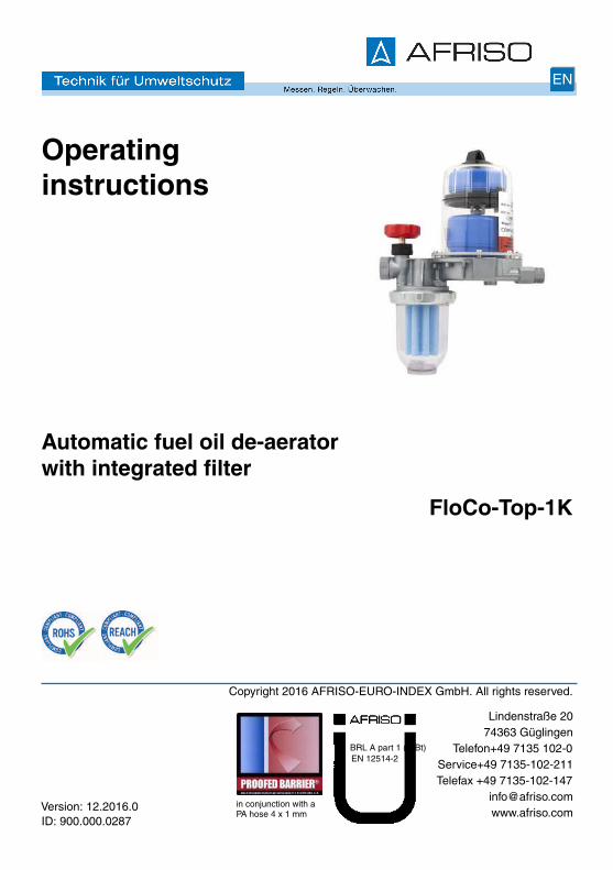
Operatinginstructions
Automatic fuel oil de-aeratorwith integrated filter
FloCo-Top-1K
2
About these operating instructions EN
FloCo-Top-1K
1 About these operating instructionsThese operating instructions describe the automatic fuel oil de-aerator withintegrated filter "FloCo-Top-1K" (also referred to as "product" in these oper-ating instructions). These operating instructions are part of the product.
• You may only use the product if you have fully read and understood theseoperating instructions.
• Verify that these operating instructions are always accessible for any typeof work performed on or with the product.
• Pass these operating instructions as well as all other product-related doc-uments on to all owners of the product.
• If you feel that these operating instructions contain errors, inconsisten-cies, ambiguities or other issues, contact the manufacturer prior to usingthe product.
There operating instructions are protected by copyright and may only beused as provided for by the corresponding copyright legislation. We reservethe right to modifications.
The manufacturer shall not be liable in any form whatsoever for direct or con-sequential damage resulting from failure to observe these operating instruc-tions or from failure to comply with directives, regulations and standards andany other statutory requirements applicable at the installation site of the prod-uct.
3
Information on safety EN
FloCo-Top-1K
2 Information on safety
2.1 Safety messages and hazard categoriesThese operating instructions contain safety messages to alert you to poten-tial hazards and risks. In addition to the instructions provided in these oper-ating instructions, you must comply with all directives, standards and safetyregulations applicable at the installation site of the product. Verify that you arefamiliar with all directives, standards and safety regulations and ensure com-pliance with them prior to using the product.
Safety messages in these operating instructions are highlighted with warningsymbols and warning words. Depending on the severity of a hazard, thesafety messages are classified according to different hazard categories.
NOTICENOTICE indicates a hazardous situation, which, if not avoided, canresult in equipment damage.
4
Information on safety EN
FloCo-Top-1K
2.2 Intended useThis product may only be used in single-line systems with return pipe con-nection for continuous de-aeration of the following liquids in oil-fired systems:
• Fuel oil EL as per DIN 51603-1- with 0 - 20 % fatty acid methyl ester (FAME) as per EN 14214
• Diesel fuel as per EN 590- with 0 - 20 % fatty acid methyl ester (FAME) as per EN 14214
Any use other than the application explicitly permitted in these operatinginstructions is not permitted and causes hazards.
Verify that the product is suitable for the application planned by you prior tousing the product. In doing so, take into account at least the following:
• All directives, standards and safety regulations applicable at the installa-tion site of the product
• All conditions and data specified for the product
• The conditions of the planned application
In addition, perform a risk assessment in view of the planned application,according to an approved risk assessment method, and implement theappropriate safety measures, based on the results of the risk assessment.Take into account the consequences of installing or integrating the productinto a system or a plant.
When using the product, perform all work and all other activities in conjunc-tion with the product in compliance with the conditions specified in the oper-ating instructions and on the nameplate, as well as with all directives, stand-ards and safety regulations applicable at the installation site of the product
5
Information on safety EN
FloCo-Top-1K
2.3 Predictable incorrect applicationThe product must never be used in the following cases and for the followingpurposes:
• Use with undiluted additives, alcohols and acids
• Use in pressure supply systems without appropriate protection precau-tions
2.4 Qualification of personnelOnly appropriately trained persons who are familiar with and understand thecontents of these operating instructions and all other pertinent product doc-umentation are authorized to work on and with this product.
These persons must have sufficient technical training, knowledge and expe-rience and be able to foresee and detect potential hazards that may becaused by using the product
All persons working on and with the product must be fully familiar with alldirectives, standards and safety regulations that must be observed for per-forming such work.
2.5 Personal protective equipment.Always wear the required personal protective equipment. When performingwork on and with the product, take into account that hazards may be presentat the installation site which do not directly result from the product itself.
2.6 Modifications to the productOnly perform work on and with the product which is explicitly described inthese operating instructions. Do not make any modifications to the productwhich are not described in these operating instructions.
6
Transport and storage EN
FloCo-Top-1K
3 Transport and storageThe product may be damaged as a result of improper transport or storage.
NOTICEDAMAGE TO THE PRODUCT• Verify compliance with the specified ambient conditions during transport or
storage of the product.• Use the original packaging when transporting the product.• Store the product in a clean and dry environment.• Verify that the product is protected against shocks and impact during trans-
port and storage.
Failure to follow these instructions can result in equipment damage.
7
Product description EN
FloCo-Top-1K
4 Product description
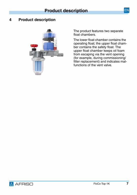
The product features two separatefloat chambers.
The lower float chamber contains theoperating float; the upper float cham-ber contains the safety float. Theupper float chamber keeps oil foamfrom escaping via the vent opening(for example, during commissioning/filter replacement) and indicates mal-functions of the vent valve.
8
Product description EN
FloCo-Top-1K
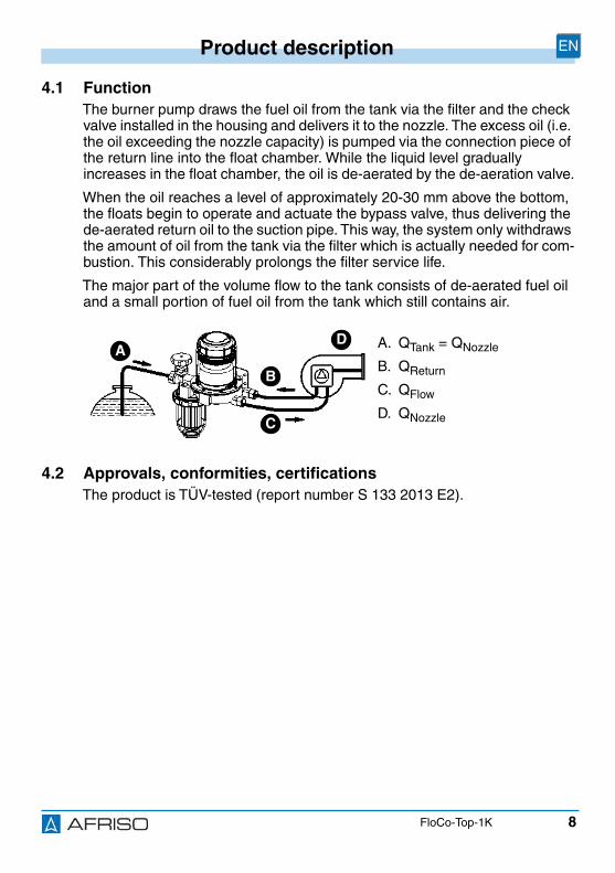
4.1 FunctionThe burner pump draws the fuel oil from the tank via the filter and the checkvalve installed in the housing and delivers it to the nozzle. The excess oil (i.e.the oil exceeding the nozzle capacity) is pumped via the connection piece ofthe return line into the float chamber. While the liquid level graduallyincreases in the float chamber, the oil is de-aerated by the de-aeration valve.
When the oil reaches a level of approximately 20-30 mm above the bottom,the floats begin to operate and actuate the bypass valve, thus delivering thede-aerated return oil to the suction pipe. This way, the system only withdrawsthe amount of oil from the tank via the filter which is actually needed for com-bustion. This considerably prolongs the filter service life.
The major part of the volume flow to the tank consists of de-aerated fuel oiland a small portion of fuel oil from the tank which still contains air.
4.2 Approvals, conformities, certificationsThe product is TÜV-tested (report number S 133 2013 E2).
A. QTank = QNozzle
B. QReturn
C. QFlow
D. QNozzle
AD
B
C

9
Product description EN
FloCo-Top-1K
4.3 Technical specifications
Parameter Value
General specifications
Dimensions (W x H x D)with short filter cup
165 x 221 x 98 mm
Burner connection G3/8 with 60° cone for burnerhose
Tank connection G3/8 at shut-off valve
Nozzle capacity Max. 100 l/h
Return flow Max. 120 l/h
Separating capacity air/gas, dependingon air content of fuel
> 4 l/h (de-aeration unit only)
> 6 l/h (as per EN 12514-3)
Mounting position Float housing vertical to the top
Operating overpressure Max. 0.7 bar (corresponds to astatic oil column of approximately8 m)
Suction vacuum Max. 0.5 bar
Test pressure 6 bar
Filter insert 50-70 µm sintered plastic (partno. 69960), see packaging labelfor other articles
Operating temperature range
Ambient Max. +60 °C
Medium Max. +60 °C
Materials
De-aerator hood Transparent plastic
Filter cup Transparent plastic
Housing Zinc die cast
10
Mounting EN
FloCo-Top-1K
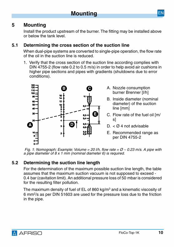
5 MountingInstall the product upstream of the burner. The fitting may be installed aboveor below the tank level.
5.1 Determining the cross section of the suction lineWhen dual-pipe systems are converted to single-pipe operation, the flow rateof the oil in the suction line is reduced.
1. Verify that the cross section of the suction line according complies withDIN 4755-2 (flow rate 0.2 to 0.5 m/s) in order to help avoid air cushions inhigher pipe sections and pipes with gradients (shutdowns due to errorconditions).
5.2 Determining the suction line lengthFor the determination of the maximum possible suction line length, the tableassumes that the maximum suction vacuum is not supposed to exceed -0.4 bar (cavitation limit). An additional pressure loss of 50 mbar is consideredfor the resulting filter pollution.
The maximum density of fuel of EL of 860 kg/m3 and a kinematic viscosity of6 mm2/s as per DIN 51603 are used for the pressure loss due to the frictionin the pipe.
A. Nozzle consumptionburner Brenner [l/h]
B. Inside diameter (nominaldiameter) of the suctionline [mm]
C. Flow rate of the fuel oil [m/s]
D. < Ø 4 not advisable
E. Recommended range asper DIN 4755-2
Fig. 1: Nomograph; Example: Volume = 20 l/h, flow rate = Ø ~ 0.23 m/s. A pipe witha pipe diameter of 8 x 1 mm (nominal diameter 6) is required.
A
CB
D
E

11
Mounting EN
FloCo-Top-1K
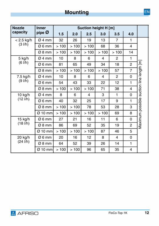
5.2.1 Maximum suction line length with lower tank level
1. If the suction line isdesigned as a self-secur-ing suction line accordingto the applicable technicalregulations, remove allcheck valves upstream ofthe product.
12
Mounting EN
FloCo-Top-1K
Nozzlecapacity
Innerpipe Ø
Suction height H [m]
1.5 2.0 2.5 3.0 3.5 4.0
< 2.5 kg/h(3 l/h)
Ø 4 mm 32 26 19 13 7 1
Max
imum
poss
ible
suct
ion
line
leng
th[m
]
Ø 6 mm > 100 > 100 > 100 68 36 4
Ø 8 mm > 100 > 100 > 100 > 100 > 100 14
5 kg/h(6 l/h)
Ø 4 mm 10 8 6 4 2 1
Ø 6 mm 81 65 49 34 18 2
Ø 8 mm > 100 > 100 > 100 > 100 57 7
7.5 kg/h(9 l/h)
Ø 4 mm 10 8 6 4 2 0
Ø 6 mm 54 43 33 22 12 1
Ø 8 mm > 100 > 100 > 100 71 38 4
10 kg/h(12 l/h)
Ø 4 mm 8 6 4 3 1 0
Ø 6 mm 40 32 25 17 9 1
Ø 8 mm > 100 > 100 78 53 28 3
Ø 10 mm > 100 > 100 > 100 > 100 69 8
15 kg/h(18 l/h)
Ø 6 mm 27 21 16 11 6 0
Ø 8 mm 86 69 52 35 19 2
Ø 10 mm > 100 > 100 > 100 87 46 5
20 kg/h(24 l/h)
Ø 6 mm 20 16 12 8 4 0
Ø 8 mm 64 52 39 26 14 1
Ø 10 mm > 100 > 100 96 65 35 4
13
Mounting EN
FloCo-Top-1K
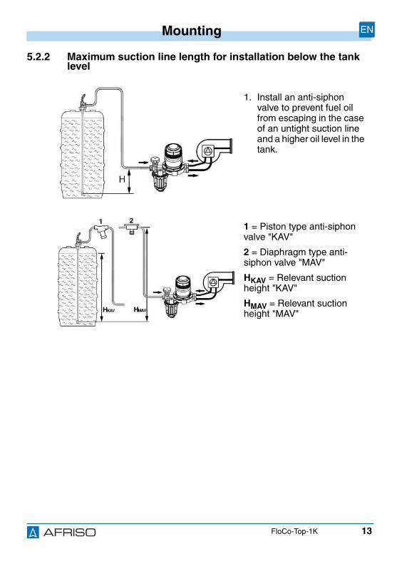
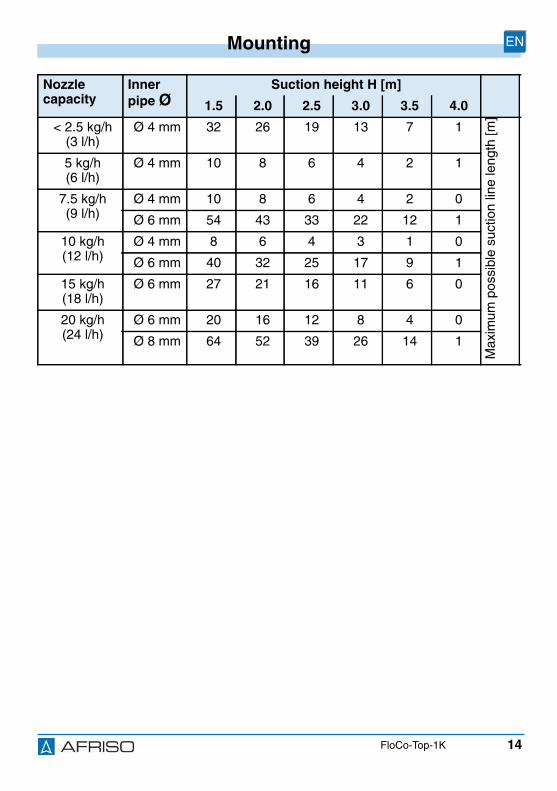
5.2.2 Maximum suction line length for installation below the tanklevel
1. Install an anti-siphonvalve to prevent fuel oilfrom escaping in the caseof an untight suction lineand a higher oil level in thetank.
1 = Piston type anti-siphonvalve "KAV"
2 = Diaphragm type anti-siphon valve "MAV"
HKAV = Relevant suctionheight "KAV"
HMAV = Relevant suctionheight "MAV"
14
Mounting EN
FloCo-Top-1K
Nozzlecapacity
Innerpipe Ø
Suction height H [m]
1.5 2.0 2.5 3.0 3.5 4.0
< 2.5 kg/h(3 l/h)
Ø 4 mm 32 26 19 13 7 1
Max
imum
poss
ible
suct
ion
line
leng
th[m
]
5 kg/h(6 l/h)
Ø 4 mm 10 8 6 4 2 1
7.5 kg/h(9 l/h)
Ø 4 mm 10 8 6 4 2 0
Ø 6 mm 54 43 33 22 12 1
10 kg/h(12 l/h)
Ø 4 mm 8 6 4 3 1 0
Ø 6 mm 40 32 25 17 9 1
15 kg/h(18 l/h)
Ø 6 mm 27 21 16 11 6 0
20 kg/h(24 l/h)
Ø 6 mm 20 16 12 8 4 0
Ø 8 mm 64 52 39 26 14 1
15
Mounting EN
FloCo-Top-1K
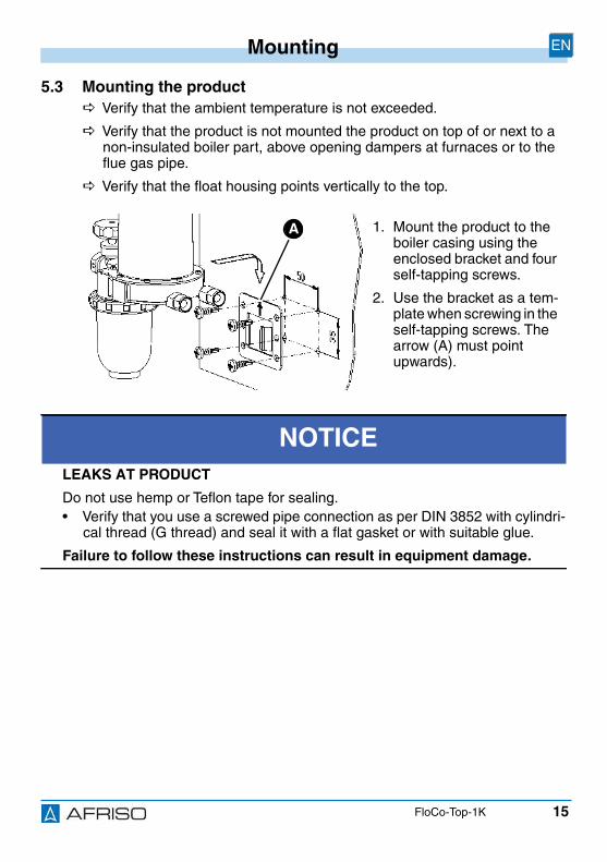
5.3 Mounting the product Verify that the ambient temperature is not exceeded.
Verify that the product is not mounted the product on top of or next to anon-insulated boiler part, above opening dampers at furnaces or to theflue gas pipe.
Verify that the float housing points vertically to the top.
1. Mount the product to theboiler casing using theenclosed bracket and fourself-tapping screws.
2. Use the bracket as a tem-plate when screwing in theself-tapping screws. Thearrow (A) must pointupwards).
NOTICELEAKS AT PRODUCT
Do not use hemp or Teflon tape for sealing.• Verify that you use a screwed pipe connection as per DIN 3852 with cylindri-
cal thread (G thread) and seal it with a flat gasket or with suitable glue.
Failure to follow these instructions can result in equipment damage.
A

16
Mounting EN
FloCo-Top-1K
3. Mount the suction line into the female thread G3/8 of the housing with acylindrical screwed pipe connection G3/8 as per DIN 3852.
4. Use a stiffener in the case of soft or semi-soft copper pipes.
5. Lock with an open ended spanner size 24 and tighten the screwed con-nection at the connection piece.
6. Mount the burner hoses. Before mounting, make sure the sealing sur-faces are clean and not damaged.
5.4 Pressure testWhen subjecting the suction pipe to a pressure test, the pressure connectionmust not be made at the product since the check valve integrated in the prod-uct does not allow the pressure to be applied to the suction line.
1. Do not include the product in the pressure test.
NOTICEDAMAGE TO THE PRODUCT• Verify that you do not interchange the flow and return connections.
Failure to follow these instructions can result in equipment damage.

17
Mounting EN
FloCo-Top-1K
5.5 Pressure lossThe product allows you to use a great variety of filter inserts. See the diagramfor the resulting pressure losses.
5.5.1 In suction mode with clean filter insert
5.5.2 In suction mode with filter insert polluted by 50 %
A. Sintered plastic insert 35µm
B. Sintered plastic insert 70µm
C. Felt
D. Steel sieve
1. Sintered plastic insert 35µm
2. Sintered plastic insert 70µm
3. Felt
4. Steel sieve
Flow rate Q [l/h]
Pre
ssur
elo
ssp
[mba
r]
A
B
DC
Flow rate Q [l/h]
Pre
ssur
elo
ssp
[mba
r]
A
B
DC
18
Mounting EN
FloCo-Top-1K
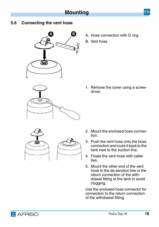
5.6 Connecting the vent hose
A. Hose connection with O ring
B. Vent hose
1. Remove the cover using a screw-driver.
2. Mount the enclosed hose connec-tion.
3. Push the vent hose onto the hoseconnection and route it back to thetank next to the suction line.
4. Fixate the vent hose with cableties.
5. Mount the other end of the venthose to the de-aeration line or thereturn connection of the with-drawal fitting at the tank to avoidclogging.
Use the enclosed hose connector forconnection to the return connectionof the withdrawal fitting.
BA
19
Operation EN
FloCo-Top-1K
6 Operation
6.1 Oil level in the float housingThe oil level depends on the operating conditions of the facility and amountsto approximately 20-50 mm in suction mode. If the oil level is higher, the floathousing may be completely filled with oil if the suction line is tight. This iscaused by the absorption of the air through the fuel oil. Over time, this resultsin a reduction of the air cushion. When the operating conditions change (forexample, decreasing oil level in the tank), the air cushion is formed again inthe float housing.
6.2 Pressure modeSince in pressure mode with an oil pump there is no gas formation caused bysuction, it is not meaningful to use the product in this mode. In pressuremode, it is recommended to use a single-line filter with return pipe connec-tion. If the system requires a fuel oil de-aerator, you can use a "Flow-Control3/K HT" with upstream filter and brass filter cup or replaceable filter cartridge.
In the case of such applications, take appropriate measures to keep themaximum permissible inlet pressure of 0.7 bar from being exceeded evenin the case of error conditions (defective pressure reducer), for example,by means of a bypass valve, a pressure switch, etc.
A drip pan must be placed below the burner hoses and the oil de-aeratorvia which leaking oil is detected and the burner is switched off.
20
Operation EN
FloCo-Top-1K
6.3 Accumulations of air in the filter cupDepending on the filter insert and the suction vacuum of the facility, the airseparated from the oil may be retained by the filter insert to a major or minordegree.
An air cushion may form upstream of the filter sieve; this air cushion is visiblein the filter cup. The size of the air cushion depends on the flow rate and thesuction pressure in the filter, i.e. more air particles may be pulled through thesieve at a great throughput compared to a slow flow rate (lower oil consump-tion by burner). When a vacuum is generated during operation of the burner,this causes the oil level to decrease in the filter cup outside of the filter sieve.The inside of the filter sieve is completely filled with filtered oil so that mal-functions cannot occur. The irregular pore structure of the standard sinteredplastic filter insert with a spatial effect causes excellent permeability of the air.
6.4 Use in flood hazard areasThe product is suitable for use in flood hazard areas; it is watertight up to 10m water column (1 bar pressure).
NOTICEINOPERABLE PRODUCT• Verify that the product is replaced after a flood.
Failure to follow these instructions can result in equipment damage.

21
Maintenance EN
FloCo-Top-1K
7 Maintenance
7.1 Maintenance intervals
When Activity
If required Clean the plastic parts with soap suds
Do not use cleaning agents containing solvents.
Annually or if required Replace the filter insert
Every 5 years Replace the burner hoses
No later than after 20years
Replace the product.
22
Troubleshooting EN
FloCo-Top-1K
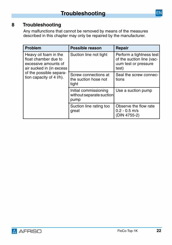
8 TroubleshootingAny malfunctions that cannot be removed by means of the measuresdescribed in this chapter may only be repaired by the manufacturer.
Problem Possible reason Repair
Heavy oil foam in thefloat chamber due toexcessive amounts ofair sucked in (in excessof the possible separa-tion capacity of 4 l/h).
Suction line not tight Perform a tightness testof the suction line (vac-uum test or pressuretest)
Screw connections atthe suction hose nottight
Seal the screw connec-tions
Initial commissioningwithout separate suctionpump
Use a suction pump
Suction line rating toogreat
Observe the flow rate0.2 - 0.5 m/s(DIN 4755-2)
23
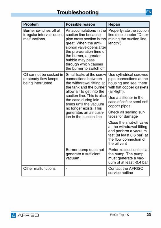
Troubleshooting EN
FloCo-Top-1K
Burner switches off atirregular intervals due tomalfunctions
Air accumulations in thesuction line becausepipe cross section is toogreat. When the anti-siphon valve opens afterthe pre-aeration time ofthe burner, a greaterbubble may passthrough which causesthe burner to switch off.
Properly rate the suctionline (see chapter "Deter-mining the suction linelength")
Oil cannot be sucked inor steady flow keepsbeing interrupted
Small leaks at the screwconnections betweenthe withdrawal fitting atthe tank and the burnerallow air to get into thesuction line. This is alsothe case during idletimes until the vacuumno longer exists. Thisgenerates an air cush-ion in the suction line
Use cylindrical screwedpipe connections at thehousing and seal themwith flat copper gaskets(air-tight).
Use a stiffener in thecase of soft or semi-softcopper pipes
Check all sealing sur-faces for damage
Close the shut-off valveat the withdrawal fittingand perform a vacuumtest (at least 0.6 bar) atthe flow connection ofthe oil vent
Burner pump does notgenerate a sufficientvacuum
Perform a suction test atthe pump. The pumpmust generate a vac-uum of at least -0.4 bar
Other malfunctions - Contact the AFRISOservice hotline
Problem Possible reason Repair
24
Decommissioning, disposal EN
FloCo-Top-1K
9 Decommissioning, disposalDispose of the product in compliance with all applicable directives, standardsand safety regulations.
10 Returning the deviceGet in touch with us before returning your product.
11 WarrantySee our terms and conditions at www.afriso.com or your purchase contractfor information on warranty.
1. Dismount the product (see chapter "Mounting", reversesequence of steps).
2. Dispose of the product.
25
Spare parts and accessories EN
FloCo-Top-1K
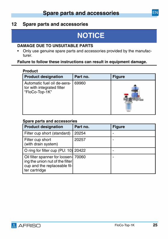
12 Spare parts and accessories
Product
Spare parts and accessories
NOTICEDAMAGE DUE TO UNSUITABLE PARTS• Only use genuine spare parts and accessories provided by the manufac-
turer.
Failure to follow these instructions can result in equipment damage.
Product designation Part no. Figure
Automatic fuel oil de-aera-tor with integrated filter"FloCo-Top-1K"
69960 -
Product designation Part no. Figure
Filter cup short (standard) 20254 -
Filter cup short(with drain system)
20257 -
O ring for filter cup (PU: 10) 20422 -
Oil filter spanner for loosen-ing the union nut of the filtercup and the replaceable fil-ter cartridge
70060 -
26
Spare parts and accessories EN
FloCo-Top-1K
Screwed pipe connectionas per DIN 3852 with flatcopper gasket:
Pipe Ø 6 mmPipe Ø 8 mmPipe Ø 10 mmPipe Ø 12 mm
20509205082051020512
-
Piston type anti-siphonvalve "KAV"
20240 -
Diaphragm type anti-siphonvalve "MAV"
20139 -
Vent hose,PVC, ø 4 x 1 mm, 20 m reel
20696 -
Product designation Part no. Figure
Version: 12.2016.0ID: 900.000.0287
Lindenstraße 2074363 Güglingen
Telefon +49 7135-102-0Service +49 7135-102-211Telefax +49 7135-102-147
Copyright 2016 AFRISO-EURO-INDEX GmbH. Tous droits réservés.
BRL A partie 1EN 12514-2
En liaison avecun tube PA 4 x 1 mm
FR
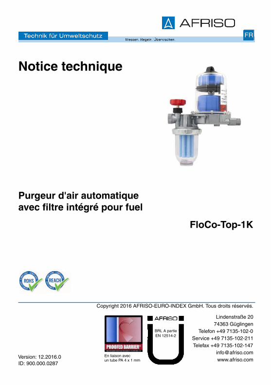
Notice technique
Purgeur d'air automatiqueavec filtre intégré pour fuel
FloCo-Top-1K
2
La présente notice technique FR
FloCo-Top-1K
1 La présente notice techniqueCette notice technique contient la description du purgeur d'air automatiqueavec filtre intégré pour fuel "FloCo-Top-1K" (dénommé ci-après "produit").Cette notice technique fait partie du produit.
• Utilisez le produit seulement après que vous aurez lu et compris intégra-lement la notice technique.
• Assurez-vous que la notice technique est disponible en permanence pourtoutes les opérations relatives au produit.
• Transmettez la notice technique et toute la documentation relative au pro-duit à tous les utilisateurs du produit.
• Si vous êtes d'avis que la notice technique contient des erreurs, descontradictions ou des ambiguïtés, adressez-vous au fabricant avant d'uti-liser le produit.
Cette notice technique est protégée au titre de la propriété intellectuelle ; elledoit être utilisée exclusivement dans le cadre autorisé par la loi. Sous réservede modifications.
La responsabilité du fabricant ou la garantie ne pourra être engagée pour desdommages ou dommages consécutifs résultant d'une inobservation desdirectives, règlements et normes en vigueur sur le lieu d'installation du pro-duit.
3
Informations sur la sécurité FR
FloCo-Top-1K
2 Informations sur la sécurité
2.1 Consignes de sécurité et classes de risquesCette notice technique contient des consignes de sécurité destinées à attirerl'attention sur les dangers et les risques. Outre les instructions contenuesdans cette notice technique, il faut vous assurer de l'observation de tous lesrèglements, normes et consignes de sécurité en vigueur sur le lieu d'instal-lation du produit. Avant d'utiliser le produit assurez-vous que tous les règle-ments, normes et consignes de sécurité sont connus et respectés.
Dans cette notice technique les consignes de sécurité sont identifiables àl'aide de symboles de mise en garde et de mots d'avertissement. En fonctionde la gravité du risque les consignes de sécurité sont réparties dans diffé-rentes classes de risques.
AVISAVIS signale une situation potentiellement dangereuse qui, si elle n'est pas évi-tée, peut entraîner un dommage matériel.
4
Informations sur la sécurité FR
FloCo-Top-1K
2.2 Utilisation conformeLe produit est destiné exclusivement à l'utilisation dans les systèmes mono-tubes avec recyclage pour la purge des liquides suivants dans les chaudièresà fuel :
• Fuel EL selon DIN 51603-1- contenant 0-20 % d'ester méthylique d'acide gras (EMAG) selon
EN 14214
• Gazole selon EN 590- contenant 0-20 % d'ester méthylique d'acide gras (EMAG) selon
EN 14214
Toute autre utilisation n'est pas conforme et cause des risques.
Avant d'utiliser le produit, assurez-vous que le produit est adapté à l'usageque vous prévoyez. À cet effet, tenez compte au moins de ce qui suit :
• Tous les règlements, normes et consignes de sécurité sur le lieu d'instal-lation
• Toutes les conditions et données spécifiées pour le produit
• Toutes les conditions d'application que vous prévoyez
En outre effectuez une évaluation des risques portant sur l'applicationconcrète que vous prévoyez à l'aide d'un procédé reconnu et prenez toutesles mesures de sécurité nécessaires correspondant au résultat. Prenezaussi en compte les conséquences possibles du montage ou de l'intégrationdu produit dans un système ou une installation.
Pendant l'utilisation du produit effectuez toutes les opérations exclusivementdans les conditions spécifiées dans cette notice technique et sur la plaquesignalétique, conformément aux données techniques spécifiées et en accordavec tous les règlements, normes et consignes de sécurité en vigueur sur lelieu d'installation.

5
Informations sur la sécurité FR
FloCo-Top-1K
2.3 Utilisation non conforme prévisibleLe produit ne doit, en particulier, pas être utilisé dans les cas suivants :
• Utilisation avec des additifs non dilués, alcools et acides
• Utilisation dans les systèmes d'alimentation de pression sans précautionsde protection correspondantes
2.4 Qualification du personnelSeul le personnel dûment qualifié est autorisé à travailler sur le produit etavec celui-ci après qu'il aura connu et compris le contenu de cette noticetechnique, ainsi que toute la documentation faisant partie du produit.
S'appuyant sur sa formation spécialisée, ses connaissances et ses expé-riences, le personnel qualifié doit être en mesure de prévoir et reconnaîtreles dangers qui peuvent être causés par l'utilisation du produit.
Tous les règlements, normes et consignes de sécurité en vigueur sur le lieud'installation doivent être connus du personnel qualifié travaillant sur le pro-duit et avec celui-ci.
2.5 Équipement de protection individuelleUtilisez toujours l'équipement de protection individuel requis. En travaillantsur le produit et avec celui-ci, tenez compte des dangers susceptibles de seprésenter sur le lieu d'installation lesquels n'émanent pas directement duproduit.
2.6 Modification du produitEn travaillant sur le produit et avec celui-ci, effectuez exclusivement les opé-rations décrites dans cette notice technique. N'effectuez pas de modifica-tions non décrites dans cette notice technique.

6
Transport et stockage FR
FloCo-Top-1K
3 Transport et stockageUn transport et un stockage inadéquats risquent de causer des dommagesau produit.
AVISDOMMAGE DU PRODUIT• Assurez-vous que les conditions ambiantes spécifiées sont respectées pen-
dant le transport et le stockage.• Utilisez l'emballage d'origine pour le transport.• Stockez le produit dans un lieu sec et propre.• Assurez-vous que le produit est à l'abri des chocs pendant le transport et le
stockage.
La non-observation de ces instructions peut causer des dommages maté-riels.

7
Description du produit FR
FloCo-Top-1K
4 Description du produit
Le produit dispose de deuxchambres de flotteur.
La chambre inférieure contient le flot-teur de service, la chambre supé-rieure le flotteur de sécurité. Lachambre supérieure empêche l'écou-lement du mousse de fuel par l'orificede purge (par exemple pendant lamise en service / le changement defiltre) et indique un éventuel dysfonc-tionnement de la soupape de purge.
8
Description du produit FR
FloCo-Top-1K
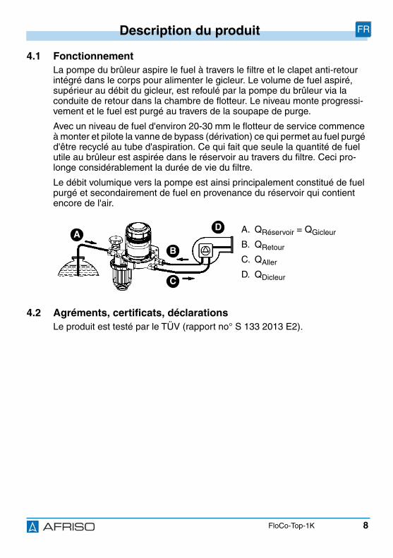
4.1 FonctionnementLa pompe du brûleur aspire le fuel à travers le filtre et le clapet anti-retourintégré dans le corps pour alimenter le gicleur. Le volume de fuel aspiré,supérieur au débit du gicleur, est refoulé par la pompe du brûleur via laconduite de retour dans la chambre de flotteur. Le niveau monte progressi-vement et le fuel est purgé au travers de la soupape de purge.
Avec un niveau de fuel d'environ 20-30 mm le flotteur de service commenceà monter et pilote la vanne de bypass (dérivation) ce qui permet au fuel purgéd'être recyclé au tube d'aspiration. Ce qui fait que seule la quantité de fuelutile au brûleur est aspirée dans le réservoir au travers du filtre. Ceci pro-longe considérablement la durée de vie du filtre.
Le débit volumique vers la pompe est ainsi principalement constitué de fuelpurgé et secondairement de fuel en provenance du réservoir qui contientencore de l'air.
4.2 Agréments, certificats, déclarationsLe produit est testé par le TÜV (rapport no° S 133 2013 E2).
A. QRéservoir = QGicleur
B. QRetour
C. QAller
D. QDicleur
AD
B
C
9
Description du produit FR
FloCo-Top-1K
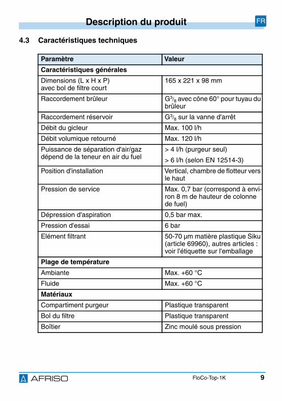
4.3 Caractéristiques techniques
Paramètre Valeur
Caractéristiques générales
Dimensions (L x H x P)avec bol de filtre court
165 x 221 x 98 mm
Raccordement brûleur G3/8 avec cône 60° pour tuyau dubrûleur
Raccordement réservoir G3/8 sur la vanne d'arrêt
Débit du gicleur Max. 100 l/h
Débit volumique retourné Max. 120 l/h
Puissance de séparation d'air/gazdépend de la teneur en air du fuel
> 4 l/h (purgeur seul)
> 6 l/h (selon EN 12514-3)
Position d'installation Vertical, chambre de flotteur versle haut
Pression de service Max. 0,7 bar (correspond à envi-ron 8 m de hauteur de colonnede fuel)
Dépression d'aspiration 0,5 bar max.
Pression d'essai 6 bar
Elément filtrant 50-70 µm matière plastique Siku(article 69960), autres articles :voir l'étiquette sur l'emballage
Plage de température
Ambiante Max. +60 °C
Fluide Max. +60 °C
Matériaux
Compartiment purgeur Plastique transparent
Bol du filtre Plastique transparent
Boîtier Zinc moulé sous pression
10
Montage FR
FloCo-Top-1K
5 MontageLe produit est à installer en amont du brûleur. L'unité peut être montée au-dessus ou en dessous du niveau du réservoir.
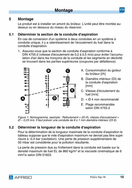
5.1 Déterminer la section de la conduite d'aspirationEn cas de conversion d'un système à deux conduites en un système àconduite unique, il y a ralentissement de l'écoulement du fuel dans laconduite d'aspiration.
1. Assurez-vous que la section de conduite d'aspiration conforme àDIN 4755-2 (vitesse d'écoulement de 0,2 à 0,5 m/s) pour éviter l'accumu-lation d'air dans les tronçons de la conduite et les segments en déclivitése trouvant dans les parties supérieures (coupures par défaillance).
5.2 Déterminer la longueur de la conduite d'aspirationPour la détermination de la longueur maximale de la conduite d'aspiration letableau suppose que le vide d'aspiration maximum ne devrait pas être supé-rieure à -0,4 bar (cavitation). Une perte de pression supplémentaire de50 mbar est considérée pour la pollution résultante.
La perte de pression due au frottement dans la conduite est basée sur ladensité maximum de fuel EL de 860 kg/m3 et la viscosité cinématique de 6mm2/s selon DIN 51603.
A. Consommation du gicleurdu brûleur [l/h]
B. Diamètre intérieur (DI) dela conduite d'aspiration[mm]
C. Vitesse d'écoulement dufuel [m/s]
D. < Ø 4 non recommandé
E. Plage recommandéeselon DIN 4755-2
Figure 1: Nomogramme, exemple : Refoulement = 20 l/h, vitesse d'écoulement =Ø ~ 0,23 m/s. Il faut prévoir une conduite de 8 x 1 mm diamètre intérieur (DI 6).
A
CB
D
E
11
Montage FR
FloCo-Top-1K
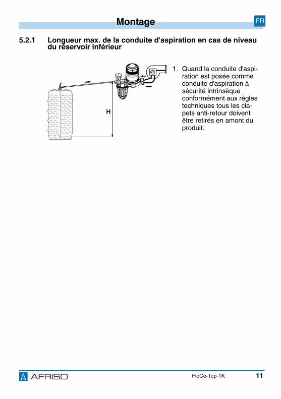
5.2.1 Longueur max. de la conduite d'aspiration en cas de niveaudu réservoir inférieur
1. Quand la conduite d'aspi-ration est posée commeconduite d'aspiration àsécurité intrinsèqueconformément aux règlestechniques tous les cla-pets anti-retour doiventêtre retirés en amont duproduit.
12
Montage FR
FloCo-Top-1K
Débit dugicleur
Ø inté-rieure detube
Hauteur d'aspiration H [m]1,5 2,0 2,5 3,0 3,5 4,0
< 2,5 kg/h(3 l/h)
Ø 4 mm 32 26 19 13 7 1
Long
ueur
max
.adm
issi
ble
dela
cond
uite
d'as
pira
tion
[m]Ø 6 mm > 100 > 100 > 100 68 36 4
Ø 8 mm > 100 > 100 > 100 > 100 > 100 14
5 kg/h(6 l/h)
Ø 4 mm 10 8 6 4 2 1
Ø 6 mm 81 65 49 34 18 2
Ø 8 mm > 100 > 100 > 100 > 100 57 7
7,5 kg/h(9 l/h)
Ø 4 mm 10 8 6 4 2 0
Ø 6 mm 54 43 33 22 12 1
Ø 8 mm > 100 > 100 > 100 71 38 4
10 kg/h(12 l/h)
Ø 4 mm 8 6 4 3 1 0
Ø 6 mm 40 32 25 17 9 1
Ø 8 mm > 100 > 100 78 53 28 3
Ø 10 mm > 100 > 100 > 100 > 100 69 8
15 kg/h(18 l/h)
Ø 6 mm 27 21 16 11 6 0
Ø 8 mm 86 69 52 35 19 2
Ø 10 mm > 100 > 100 > 100 87 46 5
20 kg/h(24 l/h)
Ø 6 mm 20 16 12 8 4 0
Ø 8 mm 64 52 39 26 14 1
Ø 10 mm > 100 > 100 96 65 35 4
13
Montage FR
FloCo-Top-1K
5.2.2 Longueur max. de la conduite d'aspiration en cas d'installa-tion en dessous du niveau du réservoir
1. Installez une valve anti-siphon pour éviter unécoulement éventuel defuel en cas de fuite dans laconduite d'aspiration oude niveau supérieur dansle réservoir (effet siphon).
1 = Valve anti-siphon à piston"KAV"
2 = Valve anti-siphon àmembrane "MAV"
HKAV = Hauteur d’aspirationeffective "KAV"
HMAV =Hauteur d’aspirationeffective "MAV"
14
Montage FR
FloCo-Top-1K
Débit dugicleur
Ø inté-rieure detube
Hauteur d'aspiration H [m]1,5 2,0 2,5 3,0 3,5 4,0
< 2,5 kg/h(3 l/h)
Ø 4 mm 32 26 19 13 7 1
Long
ueur
max
.adm
issi
ble
dela
cond
uite
d'as
pira
tion
[m]
5 kg/h(6 l/h)
Ø 4 mm 10 8 6 4 2 1
7,5 kg/h(9 l/h)
Ø 4 mm 10 8 6 4 2 0
Ø 6 mm 54 43 33 22 12 1
10 kg/h(12 l/h)
Ø 4 mm 8 6 4 3 1 0
Ø 6 mm 40 32 25 17 9 1
15 kg/h(18 l/h)
Ø 6 mm 27 21 16 11 6 0
20 kg/h(24 l/h)
Ø 6 mm 20 16 12 8 4 0
Ø 8 mm 64 52 39 26 14 1
15
Montage FR
FloCo-Top-1K
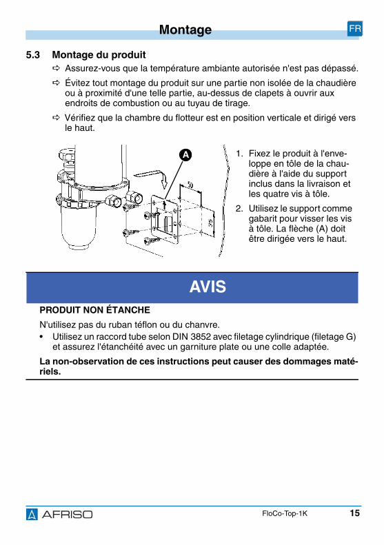
5.3 Montage du produit Assurez-vous que la température ambiante autorisée n'est pas dépassé.
Évitez tout montage du produit sur une partie non isolée de la chaudièreou à proximité d'une telle partie, au-dessus de clapets à ouvrir auxendroits de combustion ou au tuyau de tirage.
Vérifiez que la chambre du flotteur est en position verticale et dirigé versle haut.
1. Fixez le produit à l'enve-loppe en tôle de la chau-dière à l'aide du supportinclus dans la livraison etles quatre vis à tôle.
2. Utilisez le support commegabarit pour visser les visà tôle. La flèche (A) doitêtre dirigée vers le haut.
AVISPRODUIT NON ÉTANCHE
N'utilisez pas du ruban téflon ou du chanvre.• Utilisez un raccord tube selon DIN 3852 avec filetage cylindrique (filetage G)
et assurez l'étanchéité avec un garniture plate ou une colle adaptée.
La non-observation de ces instructions peut causer des dommages maté-riels.
A
16
Montage FR
FloCo-Top-1K
3. Utilisez un raccord cylindrique G3/8 selon DIN 3852 afin de raccorder latube d'aspiration au taraudage G3/8 du boîtier.
4. Utilisez une douille de renfort en cas de tube cuivre mou ou cuivre demi-dur.
5. Utilisez une clé plate de 24 pour serrer les raccords.
6. Raccordez les flexibles du brûleur. Les surfaces d'étanchéité doivent êtreintactes et propres.
5.4 Essai de pressionLors de l'essai de pression de la conduite d'aspiration, ne raccordez pas lapression au produit, car le clapet anti-retour incorporé à l'appareil ne permetpas d'appliquer la pression à la conduite d'aspiration.
1. Le produit ne doit pas être inclus à l'essai de pression.
AVISDOMMAGE DU PRODUIT• Assurez-vous que les raccordements aller et retour ne sont pas inversés.
La non-observation de ces instructions peut causer des dommages maté-riels.
17
Montage FR
FloCo-Top-1K
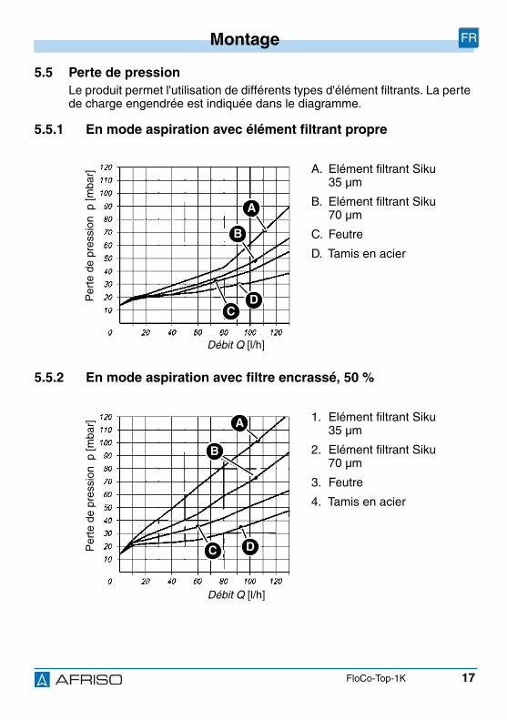
5.5 Perte de pressionLe produit permet l'utilisation de différents types d'élément filtrants. La pertede charge engendrée est indiquée dans le diagramme.
5.5.1 En mode aspiration avec élément filtrant propre
5.5.2 En mode aspiration avec filtre encrassé, 50 %
A. Elément filtrant Siku35 µm
B. Elément filtrant Siku70 µm
C. Feutre
D. Tamis en acier
1. Elément filtrant Siku35 µm
2. Elément filtrant Siku70 µm
3. Feutre
4. Tamis en acier
Débit Q [l/h]
Per
tede
pres
sion
p[m
bar]
A
B
DC
Débit Q [l/h]
Per
tede
pres
sion
p[m
bar] A
B
DC
18
Montage FR
FloCo-Top-1K
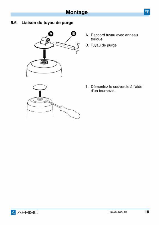
5.6 Liaison du tuyau de purge
A. Raccord tuyau avec anneautorique
B. Tuyau de purge
1. Démontez le couvercle à l'aided'un tournevis.
BA
19
Montage FR
FloCo-Top-1K
2. Montez le raccord tuyau fourni.
3. Poussez le tuyau de purge sur leraccord de tuyau et le poser lelong de la ligne d'aspiration vers leréservoir.
4. Fixez le tuyau de purge à l'aide decolliers.
5. Raccordez l'autre extrémité dutuyau à la conduite d'aspiration ouau raccord de retour de l'unité devidange pour empêcher une obtu-ration possible de la conduite.
Le raccord au raccord de retour del'unité de vidange peut être effectué àl'aide de pièce de raccordementtuyau fourni.
20
Service FR
FloCo-Top-1K
6 Service
6.1 Niveau du fuel dans la chambre du flotteurLe niveau du fuel dépend des caractéristiques techniques de fonctionnementde l'installation; en mode aspiration il se situe à environ 20-50 mm. Lorsquele niveau de fuel est plus élevé, la conduite d'aspiration étant étanche, lachambre du flotteur peut être plein de fuel. Ceci est provoqué par l'absorptionde l'air par le fuel. Cet effet élimine progressivement le coussin d'air. Si lesconditions de service changent (pas exemple baisse de niveau de fuel dansle réservoir), un coussin d'air va se recréer dans la chambre du flotteur.
6.2 Mode pressionEn cas d'utilisation d'un pompe en mode pression, il n'est pas utile d'installerle produit car il n'y a pas d'air à évacuer provenant de l'aspiration. Dans cecas, un filtre monotube avec retour est préférable. Si l'installation nécessitetoutefois un purgeur d'air pour fuel, on pourra utiliser un "Flow-Control 3/KHT" avec un filtre en amont et un bol de filtre en laiton ou une cartouche defiltre interchangeable.
Pour cette application prenez des précautions appropriées (pressostat,soupape de décharge, etc.) ; en cas d'incident (réducteur de pressiondéfectueux, etc.), la pression d'alimentation ne doit pas excéder 0,7 bar.
Prévoyez un bac de rétention sous les flexibles du brûleur et le purgeurd'air pour fuel afin de permettre de détecter une fuite de fuel et assurerl'arrêt du brûleur.
21
Service FR
FloCo-Top-1K
6.3 Accumulation d'air dans le bol de filtreEn fonction du type d'élément filtrant et de la pression d'aspiration spécifiquede l'installation, l'élément filtrant peut plus ou moins retenir l'air séparé del'huile.
En amont du tamis de filtre, un coussin d'air peut se former, il est visible dansle bol de filtre. La dimension du coussin d'air dépend de la vitesse d'écoule-ment et de la pression d'aspiration dans le filtre, cela revient à dire que, si ledébit est important, les particules d'air pouvant être entraînées dans le tamissont plus nombreuses qu'avec une faible vitesse d'écoulement (consomma-tion moindre de fuel dans le brûleur). Conséquence : au cours du fonctionne-ment du brûleur pendant lequel un vide est créé, le niveau d'huile descenddans le bol de filtre à l'extérieur du tamis de filtre. L'intérieur du tamis de filtreest complètement rempli remplie de fuel filtrée de sorte qu'une panne defonctionnement est exclue. La structure de l'élément filtrant en Siku standardà pores disposées irrégulièrement sur la surface assure une très bonne per-méabilité à l'air.
6.4 Utilisation dans zones à risque d'inondationLe produit est approprié à l'utilisation dans des zones à risque d'inondationet étanche à l'eau jusqu'à une colonne d'eau de 10 m (1 bar pression).
AVISPRODUIT NON OPÉRATIONNEL• Remplacez le produit après une inondation.
La non-observation de ces instructions peut causer des dommages maté-riels.

22
Maintenance FR
FloCo-Top-1K
7 Maintenance
7.1 Intervalles de maintenance
Quand Opération
Si nécessaire Nettoyez les parties plastiques avec mousse desavon.
N' utilisez pas de produits contenant de solvants.
Annuellement ou sinécessaire
Replacez l'élément filtrant
Tous les 5 ans Remplacez les flexibles de brûleur
Après 20 ans Remplacez le produit
23
Suppression des dérangements FR
FloCo-Top-1K
8 Suppression des dérangementsLes dérangements ne figurant pas dans les mesures décrites dans ce cha-pitre doivent être éliminés uniquement par le fabricant.
Problème Cause possible Action corrective
Mousse dans lachambre de flotteurcausé par une volumeexcessive d'air aspiré(supérieur à la capacitéde purge 4 l/h)
Fuite dans la conduited'aspiration
Effectuez un essaid'étanchéité de laconduite d'aspiration(pression ou dépres-sion)
Raccords non étanchesdans le tube l'aspiration
Assurez-vous de l'étan-chéité des raccords
Première mise en ser-vice sans pompe d'aspi-ration
Utilisez une pomped'aspiration
Conduite d'aspirationsurdimensionnée
Veillez la vitesse d'écou-lement 0,2 - 0,5 m/s(DIN 4755-2 )
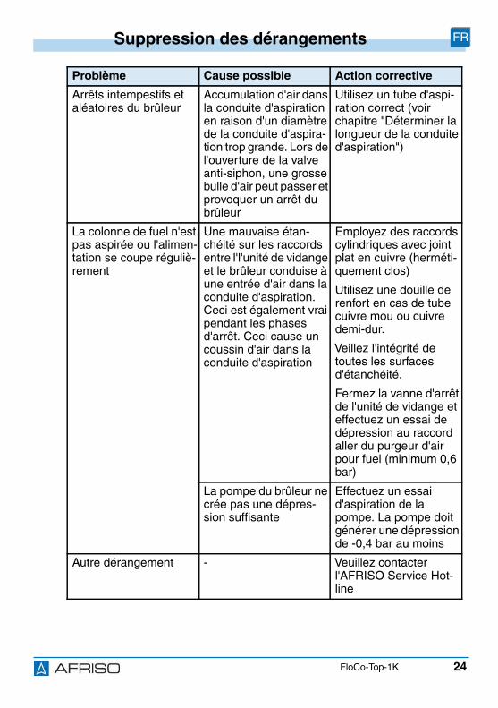
24
Suppression des dérangements FR
FloCo-Top-1K
Arrêts intempestifs etaléatoires du brûleur
Accumulation d'air dansla conduite d'aspirationen raison d'un diamètrede la conduite d'aspira-tion trop grande. Lors del'ouverture de la valveanti-siphon, une grossebulle d'air peut passer etprovoquer un arrêt dubrûleur
Utilisez un tube d'aspi-ration correct (voirchapitre "Déterminer lalongueur de la conduited'aspiration")
La colonne de fuel n'estpas aspirée ou l'alimen-tation se coupe réguliè-rement
Une mauvaise étan-chéité sur les raccordsentre l'l'unité de vidangeet le brûleur conduise àune entrée d'air dans laconduite d'aspiration.Ceci est également vraipendant les phasesd'arrêt. Ceci cause uncoussin d'air dans laconduite d'aspiration
Employez des raccordscylindriques avec jointplat en cuivre (herméti-quement clos)
Utilisez une douille derenfort en cas de tubecuivre mou ou cuivredemi-dur.
Veillez l'intégrité detoutes les surfacesd'étanchéité.
Fermez la vanne d'arrêtde l'unité de vidange eteffectuez un essai dedépression au raccordaller du purgeur d'airpour fuel (minimum 0,6bar)
La pompe du brûleur necrée pas une dépres-sion suffisante
Effectuez un essaid'aspiration de lapompe. La pompe doitgénérer une dépressionde -0,4 bar au moins
Autre dérangement - Veuillez contacterl'AFRISO Service Hot-line
Problème Cause possible Action corrective
25
Mise hors service et élimination FR
FloCo-Top-1K
9 Mise hors service et éliminationPour éliminer le produit, conformez-vous aux règlements, normes etconsignes de sécurité en vigueur.
10 RetourAvant de retourner le produit, il faut que vous preniez contact avec nous.
11 GarantieLes informations sur la garantie figurent dans nos "Conditions générales devente" sur le site www.afriso.com ou dans votre contrat de vente.
1. Démontez le produit (voir chapitre "Montage", effectuezles opérations en ordre inverse).
2. Éliminez le produit.
26
Pièces détachées et accessoires FR
FloCo-Top-1K
12 Pièces détachées et accessoires
Produit
Pièces détachées et accessoires
AVISDOMMAGES DUS À DES PIÈCES INADAPTÉES• N'utilisez que des accessoires et des pièces détachées d'origine provenant
du fabricant.
La non-observation de ces instructions peut causer des dommages maté-riels.
Désignation de l'article Référence Figure
Purgeur d'air automatiqueavec filtre intégré pour fuel"FloCo-Top-1K"
69960 -
Désignation de l'article Référence Figure
Bol de filtre court (stan-dard)
20254 -
Bol de filtre court(avec dispositif de vidange)
20257 -
Anneau torique pour bol defiltre (cond. par :10)
20422 -
Clé pour filtres à huile pourdesserrer l'écrou raccorddu bol de filtre et la car-touche de filtre interchan-geable
70060 -
27
Pièces détachées et accessoires FR
FloCo-Top-1K
Raccord tube selonDIN 3852 avec garnitureplate en cuivre :
Tube Ø 6 mmTube Ø 8 mmTube Ø 10 mmTube Ø 12 mm
20509205082051020512
-
Valve anti-siphon à piston"KAV"
20240 -
Valve anti-siphon àmembrane "MAV"
20139 -
Tuyau de purge,PVC, Ø 4 x 1 mm, 20 m rou-leau
20696 -
Désignation de l'article Référence Figure

Versione: 12.2016.0ID: 900.000.0287
Lindenstraße 2074363 Güglingen
Telefono +49 7135-102-0Service +49 7135-102-211Telefax +49 7135-102-147
Copyright 2016 AFRISO-EURO-INDEX GmbH. Tutti i diritti sono riservati.
BRL A Parte 1aEN 12514-2
in combinazione con untubo PA 4 x 1 mm
IT
Istruzioni per l’uso
Neutralizzatore aria automatico per gasolio confiltro integrato
FloCo-Top-1K

2
Su queste Istruzioni per l'uso IT
FloCo-Top-1K
1 Su queste Istruzioni per l'usoQueste Istruzioni per l'uso descrivono il neutralizzatore aria automatico pergasolio con filtro integrato "FloCo-Top-1K" (nel proseguio anche "prodotto").Le presenti Istruzioni per l’uso costituiscono parte del prodotto.
• L'utilizzo del prodotto è permesso soltanto dopo aver letto e capito com-pletamente le Istruzioni per l'uso.
• Assicurate che le Istruzioni per l'uso siano disponibili per ogni interventosul prodotto e ogni lavoro con il prodotto.
• Consegnate le Istruzioni per l'uso e tutta la documentazione relativa alprodotto a tutti gli utilizzatori del prodotto.
• Se siete dell'avviso che le Istruzioni per l'uso contengano errori, contrad-dizioni o non siano chiare, rivolgetevi al produttore prima di utilizzare ilprodotto.
Queste Istruzioni per l'uso sono protette da diritto d'autore e il loro utilizzo èriservato al contesto legalmente ammesso. Con riserva di modifiche.
L’azienda produttrice declina ogni responsabilità e garanzia per danni direttie conseguenti che risultano dalla mancata osservanza delle Istruzioni perl'uso nonché delle disposizioni, prescrizioni e norme valide sul postod'impiego del prodotto.
3
Informazioni sulla sicurezza IT
FloCo-Top-1K
2 Informazioni sulla sicurezza
2.1 Avvertenze e classi di pericolositàQueste Istruzioni per l'uso contengono avvertenze che richiamano l'atten-zione a pericoli e rischi. In aggiunta alle avvertenze riportate nelle Istruzioniper l'uso sono da rispettare tutte le disposizioni, prescrizioni e norme di sicu-rezza vigenti sul posto d'impiego del prodotto. Prima di utilizzare il prodotto,assicurare di conoscere tutte le disposizioni, prescrizioni e norme di sicu-rezza vigenti e di averle rispettate.
Le avvertenze in queste Istruzioni per l'uso sono contrassegnate da simbolidi avvertimento e parole di avvertenza. A dipendere dalla serietà della situa-zione di pericolo le avvertenze sono suddivise in varie classi di pericolosità.
INDICAZIONE CAUTELATIVAL'INDICAZIONE CAUTELATIVA richiama l'attenzione a una situazione poten-zialmente pericolosa, che può causare danni in caso di non osservanza.
4
Informazioni sulla sicurezza IT
FloCo-Top-1K
2.2 Uso conformeQuesto prodotto è stato adatto esclusivamente all’impiego in sistemi a lineasingola con riconduzione del ritorno, per la neutralizzazione continua deiseguenti liquidi in impianti di combustione del gasolio:
• Olio combustibile EL secondo DIN 51603-1- con il 0-20 % di esteri metilici di acidi grassi (FAME) secondo EN 14214
• Carburante per diesel secondo EN 590- con il 0-20 % di esteri metilici di acidi grassi (FAME) secondo EN 14214
Ogni altro utilizzo è da considerarsi non conforme e causa pericoli.
Prima di utilizzare il prodotto, assicurare che sia adatto allo scopo previsto.Così facendo, tenete conto almeno dei seguenti punti:
• tutte le disposizioni, norme e prescrizioni di sicurezza vigenti sul postod'impiego
• tutte le condizioni e i dati specificati per il prodotto
• le condizioni dell'applicazione da voi prevista.
Eseguite inoltre una valutazione dei rischi relativa all'applicazione concretada voi prevista con un procedimento riconosciuto e provvedete alle necessa-rie misure di sicurezza in base al risultato. Tenete conto anche delle possibiliconseguenze dell'installazione o integrazione del prodotto in un sistema oimpianto.
Quando utilizzate il prodotto, eseguite tutti i lavori esclusivamente nel rispettodelle condizioni specificate nelle Istruzioni per l'uso e sulla targhetta conosci-tiva, nell'ambito dei dati tecnici specificati e in osservanza di tutte le disposi-zioni norme e prescrizioni di sicurezza vigenti sul luogo d'impiego.
5
Informazioni sulla sicurezza IT
FloCo-Top-1K
2.3 Uso scorretto prevedibileIl prodotto non può essere utilizzato in particolar modo nei seguenti casi e peri seguenti scopi:
• impiego in additivi, alcool e acidi non diluiti
• impiego in impianti di alimentazione di pressione non dotate delle corri-spondenti misure di protezione
2.4 Qualifica del personaleI lavori con e a questo prodotto sono prerogativa di personale specializzato,che conosce ed ha capito i contenuti di queste Istruzioni per l'uso e tutta ladocumentazione che fa parte del prodotto.
In base alla loro formazione professionale, le loro conoscenze ed esperienze,il personale specializzato deve essere in grado di prevedere e riconoscerepossibili rischi e causati dall'utilizzo del prodotto.
Il personale specializzato deve essere a conoscenza di tutte le disposizioni,norme e prescrizioni di sicurezza vigenti che si riferiscono ai lavori con e alprodotto.
2.5 Dispositivi di protezione individualeL'utilizzo dei necessari dispositivi di protezione individuale *e obbligatorio.Durante il lavoro con e al prodotto, tenete conto anche che sul luogod'impiego possono nascere pericolo che non derivano direttamente dal pro-dotto.
2.6 Modifiche del prodottoEseguite esclusivamente i lavori con e al prodotto descritti nelle Istruzioni perl'uso. Non apportate modifiche al prodotto che non sono descritte nelle Istru-zioni per l'uso.
6
Trasporto e magazzinaggio IT
FloCo-Top-1K
3 Trasporto e magazzinaggioI prodotto può riportare danni da trasporto e magazzinaggio non adeguato.
INDICAZIONE CAUTELATIVADANNEGGIAMENTO DEL PRODOTTO• Assicurare che le condizioni ambientali specificate per il trasporto e il magaz-
zinaggio siano rispettate.• Per il trasporto, utilizzate l'imballaggio originale.• Immagazzinate il prodotto solo in ambiente asciutto e pulito.• Assicurare che il prodotto sia prodotto contro urti durante il trasporto e il
magazzinaggio.
La mancata osservanza di queste indicazioni può causare danni materiali.

7
Descrizione del prodotto IT
FloCo-Top-1K
4 Descrizione del prodotto
Il prodotto dispone di due camerecon galleggiante separate.
Nella camera inferiore si trova il gal-leggiante di lavoro, nella camerasuperiore il galleggiante di sicurezza.La camera superiore evita la fuoriu-scita di schiuma di gasolio dall’aper-tura di sfogo (ad esempio in occa-sione della messa in esercizio /sostituzione del filtro) e segnalaeventuali malfunzionamenti della val-vola di sfiato.

8
Descrizione del prodotto IT
FloCo-Top-1K
4.1 FunzioneLa pompa del bruciatore aspira il gasolio dal serbatoio attraverso il filtro e lavalvola di non ritorno montata nell’involucro e lo convoglia all’ugello. La quan-tità di gasolio che eccede la prestazione dell’ugello viene pompata nellacamera con galleggiante attraverso il bocchettone del tubo di ritorno. Qui,man mano che il livello di liquido sale, il gasolio viene sfiatato attraverso lavalvola di sfiato.
A un livello di gasolio di ca. 20-30 mm sopra il fondo, il galleggiante inizia adandare in sospensione attivando la valvola di bypass che riconvoglia il gaso-lio sfiatato alla tubatura di aspirazione. In questo modo viene aspirata dal ser-batoio attraverso il filtro solo la quantità di gasolio effettivamente necessariaper la combustione. La durata utile del filtro risulta notevolmente maggiore.
Il flusso di volume verso la pompa è composto per la maggior parte di gasoliosfiatato e, per una parte minore, di gasolio dal serbatoio che contiene ancorauna componente d’aria.
4.2 Documenti di omologazione, certificati, dichiarazioniIl prodotto è omologato dal TÜV (rapporto Nº S 133 2013 E 2).
A. Qserbatoio = Qugello
B. Qritorno
C. Qmandata
D. Qugello
AD
B
C
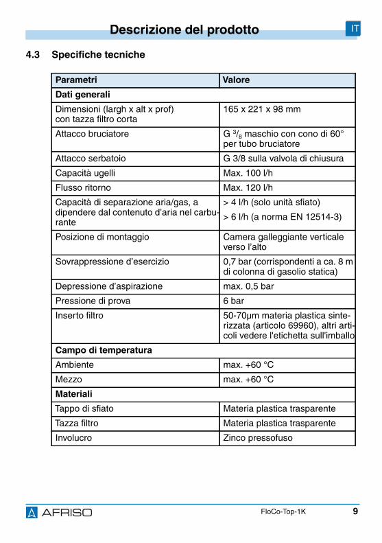
9
Descrizione del prodotto IT
FloCo-Top-1K
4.3 Specifiche tecniche
Parametri Valore
Dati generali
Dimensioni (largh x alt x prof)con tazza filtro corta
165 x 221 x 98 mm
Attacco bruciatore G 3/8 maschio con cono di 60°per tubo bruciatore
Attacco serbatoio G 3/8 sulla valvola di chiusura
Capacità ugelli Max. 100 l/h
Flusso ritorno Max. 120 l/h
Capacità di separazione aria/gas, adipendere dal contenuto d’aria nel carbu-rante
> 4 l/h (solo unità sfiato)
> 6 l/h (a norma EN 12514-3)
Posizione di montaggio Camera galleggiante verticaleverso l’alto
Sovrappressione d’esercizio 0,7 bar (corrispondenti a ca. 8 mdi colonna di gasolio statica)
Depressione d’aspirazione max. 0,5 bar
Pressione di prova 6 bar
Inserto filtro 50-70µm materia plastica sinte-rizzata (articolo 69960), altri arti-coli vedere l'etichetta sull'imballo
Campo di temperatura
Ambiente max. +60 °C
Mezzo max. +60 °C
Materiali
Tappo di sfiato Materia plastica trasparente
Tazza filtro Materia plastica trasparente
Involucro Zinco pressofuso
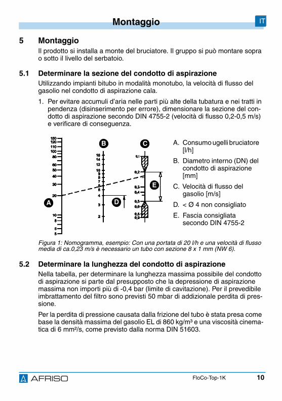
10
Montaggio IT
FloCo-Top-1K
5 MontaggioIl prodotto si installa a monte del bruciatore. Il gruppo si può montare soprao sotto il livello del serbatoio.
5.1 Determinare la sezione del condotto di aspirazioneUtilizzando impianti bitubo in modalità monotubo, la velocità di flusso delgasolio nel condotto di aspirazione cala.
1. Per evitare accumuli d’aria nelle parti più alte della tubatura e nei tratti inpendenza (disinserimento per errore), dimensionare la sezione del con-dotto di aspirazione secondo DIN 4755-2 (velocità di flusso 0,2-0,5 m/s)e verificare di conseguenza.
5.2 Determinare la lunghezza del condotto di aspirazioneNella tabella, per determinare la lunghezza massima possibile del condottodi aspirazione si parte dal presupposto che la depressione di aspirazionemassima non importi più di -0,4 bar (limite di cavitazione). Per il prevedibileimbrattamento del filtro sono previsti 50 mbar di addizionale perdita di pres-sione.
Per la perdita di pressione causata dalla frizione del tubo è stata presa comebase la densità massima del gasolio EL di 860 kg/m³ e una viscosità cinema-tica di 6 mm²/s, come previsto dalla norma DIN 51603.
A. Consumo ugelli bruciatore[l/h]
B. Diametro interno (DN) delcondotto di aspirazione[mm]
C. Velocità di flusso delgasolio [m/s]
D. < Ø 4 non consigliato
E. Fascia consigliatasecondo DIN 4755-2
Figura 1: Nomogramma, esempio: Con una portata di 20 l/h e una velocità di flussomedia di ca.0,23 m/s è necessario un tubo con sezione 8 x 1 mm (NW 6).
A
CB
D
E
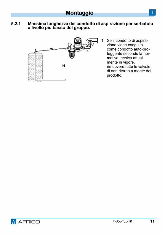
11
Montaggio IT
FloCo-Top-1K
5.2.1 Massima lunghezza del condotto di aspirazione per serbatoioa livello più basso del gruppo.
1. Se il condotto di aspira-zione viene eseguitocome condotto auto-pro-teggente secondo la nor-mativa tecnica attual-mente in vigore,rimuovere tutte le valvoledi non ritorno a monte delprodotto.
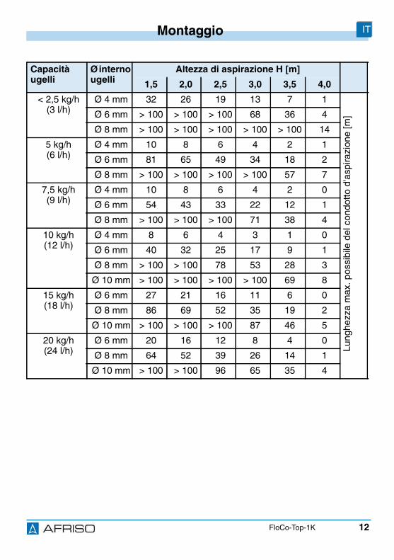
12
Montaggio IT
FloCo-Top-1K
Capacitàugelli
Ø internougelli
Altezza di aspirazione H [m]
1,5 2,0 2,5 3,0 3,5 4,0
< 2,5 kg/h(3 l/h)
Ø 4 mm 32 26 19 13 7 1
Lung
hezz
am
ax.p
ossi
bile
delc
ondo
ttod'
aspi
razi
one
[m]Ø 6 mm > 100 > 100 > 100 68 36 4
Ø 8 mm > 100 > 100 > 100 > 100 > 100 14
5 kg/h(6 l/h)
Ø 4 mm 10 8 6 4 2 1
Ø 6 mm 81 65 49 34 18 2
Ø 8 mm > 100 > 100 > 100 > 100 57 7
7,5 kg/h(9 l/h)
Ø 4 mm 10 8 6 4 2 0
Ø 6 mm 54 43 33 22 12 1
Ø 8 mm > 100 > 100 > 100 71 38 4
10 kg/h(12 l/h)
Ø 4 mm 8 6 4 3 1 0
Ø 6 mm 40 32 25 17 9 1
Ø 8 mm > 100 > 100 78 53 28 3
Ø 10 mm > 100 > 100 > 100 > 100 69 8
15 kg/h(18 l/h)
Ø 6 mm 27 21 16 11 6 0
Ø 8 mm 86 69 52 35 19 2
Ø 10 mm > 100 > 100 > 100 87 46 5
20 kg/h(24 l/h)
Ø 6 mm 20 16 12 8 4 0
Ø 8 mm 64 52 39 26 14 1
Ø 10 mm > 100 > 100 96 65 35 4
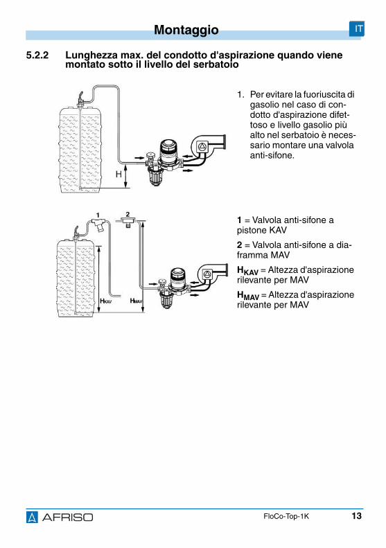
13
Montaggio IT
FloCo-Top-1K
5.2.2 Lunghezza max. del condotto d'aspirazione quando vienemontato sotto il livello del serbatoio
1. Per evitare la fuoriuscita digasolio nel caso di con-dotto d'aspirazione difet-toso e livello gasolio piùalto nel serbatoio è neces-sario montare una valvolaanti-sifone.
1 = Valvola anti-sifone apistone KAV
2 = Valvola anti-sifone a dia-framma MAV
HKAV = Altezza d'aspirazionerilevante per MAV
HMAV = Altezza d'aspirazionerilevante per MAV
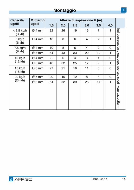
14
Montaggio IT
FloCo-Top-1K
Capacitàugelli
Ø internougelli
Altezza di aspirazione H [m]
1,5 2,0 2,5 3,0 3,5 4,0
< 2,5 kg/h(3 l/h)
Ø 4 mm 32 26 19 13 7 1
Lung
hezz
am
ax.p
ossi
bile
delc
ondo
ttod'
aspi
razi
one
[m]
5 kg/h(6 l/h)
Ø 4 mm 10 8 6 4 2 1
7,5 kg/h(9 l/h)
Ø 4 mm 10 8 6 4 2 0
Ø 6 mm 54 43 33 22 12 1
10 kg/h(12 l/h)
Ø 4 mm 8 6 4 3 1 0
Ø 6 mm 40 32 25 17 9 1
15 kg/h(18 l/h)
Ø 6 mm 27 21 16 11 6 0
20 kg/h(24 l/h)
Ø 6 mm 20 16 12 8 4 0
Ø 8 mm 64 52 39 26 14 1
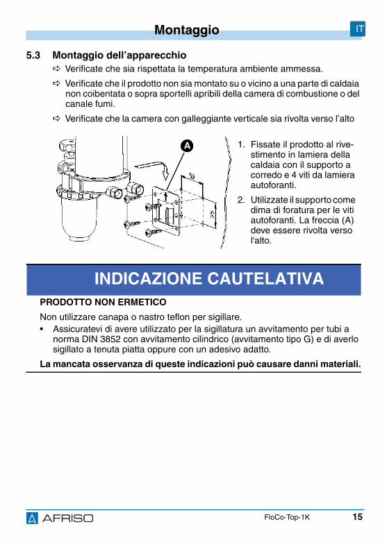
15
Montaggio IT
FloCo-Top-1K
5.3 Montaggio dell’apparecchio Verificate che sia rispettata la temperatura ambiente ammessa.
Verificate che il prodotto non sia montato su o vicino a una parte di caldaianon coibentata o sopra sportelli apribili della camera di combustione o delcanale fumi.
Verificate che la camera con galleggiante verticale sia rivolta verso l’alto
1. Fissate il prodotto al rive-stimento in lamiera dellacaldaia con il supporto acorredo e 4 viti da lamieraautoforanti.
2. Utilizzate il supporto comedima di foratura per le vitiautoforanti. La freccia (A)deve essere rivolta versol'alto.
INDICAZIONE CAUTELATIVAPRODOTTO NON ERMETICO
Non utilizzare canapa o nastro teflon per sigillare.• Assicuratevi di avere utilizzato per la sigillatura un avvitamento per tubi a
norma DIN 3852 con avvitamento cilindrico (avvitamento tipo G) e di averlosigillato a tenuta piatta oppure con un adesivo adatto.
La mancata osservanza di queste indicazioni può causare danni materiali.
A
16
Montaggio IT
FloCo-Top-1K
3. Sigillare il condotto di aspirazione nell’avvitamento femmina G 3/8dell’involucro con l'avvitamento per tubo cilindrico G 3/8 secondo DIN3852.
4. Usare una guaina di supporto per tubi di rame morbido o semi-duro.
5. Tenere in posizione con chiave a forchetta con passo di 24 e stringerel’avvitamento presso il raccordo di attacco.
6. Montare i tubi del bruciatore. Fare attenzione che le superfici di tenutasiano pulite e non danneggiate.
5.4 Prova di pressionePer la prova di pressione del condotto di aspirazione non collegare il tubo diprova al prodotto perché la valvola di non ritorno integrata nell’apparecchionon permette la trasmissione della pressione al condotto d’aspirazione.
1. Non includere il prodotto nella prova di pressione.
INDICAZIONE CAUTELATIVADANNEGGIAMENTO DEL PRODOTTO• Non scambiare gli attacchi di mandata e ritorno.
La mancata osservanza di queste indicazioni può causare danni materiali.
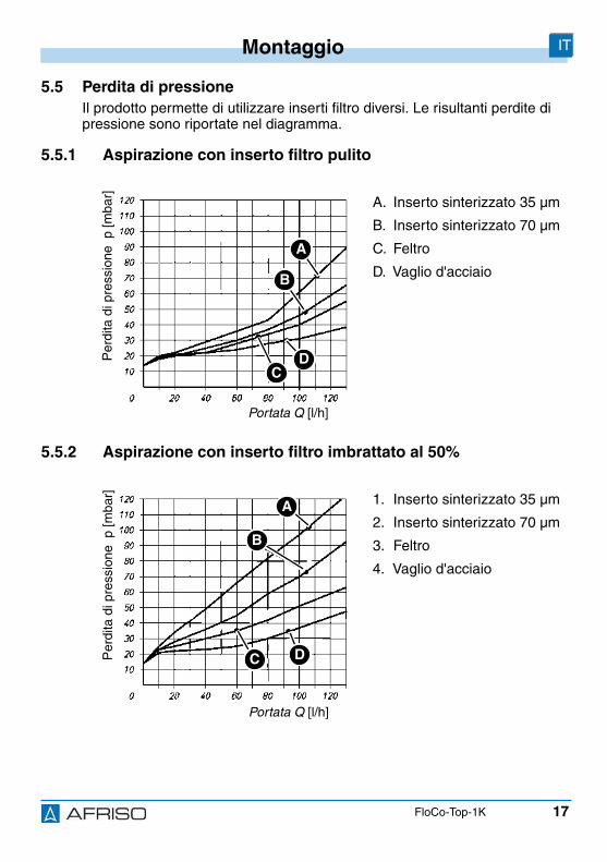
17
Montaggio IT
FloCo-Top-1K
5.5 Perdita di pressioneIl prodotto permette di utilizzare inserti filtro diversi. Le risultanti perdite dipressione sono riportate nel diagramma.
5.5.1 Aspirazione con inserto filtro pulito
5.5.2 Aspirazione con inserto filtro imbrattato al 50%
A. Inserto sinterizzato 35 µm
B. Inserto sinterizzato 70 µm
C. Feltro
D. Vaglio d'acciaio
1. Inserto sinterizzato 35 µm
2. Inserto sinterizzato 70 µm
3. Feltro
4. Vaglio d'acciaio
Portata Q [l/h]
Per
dita
dipr
essi
one
p[m
bar]
A
B
DC
Portata Q [l/h]
Per
dita
dipr
essi
one
p[m
bar]
A
B
DC
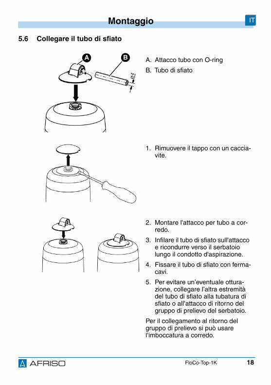
18
Montaggio IT
FloCo-Top-1K
5.6 Collegare il tubo di sfiato
A. Attacco tubo con O-ring
B. Tubo di sfiato
1. Rimuovere il tappo con un caccia-vite.
2. Montare l'attacco per tubo a cor-redo.
3. Infilare il tubo di sfiato sull'attaccoe ricondurre verso il serbatoiolungo il condotto d'aspirazione.
4. Fissare il tubo di sfiato con ferma-cavi.
5. Per evitare un’eventuale ottura-zione, collegare l’altra estremitàdel tubo di sfiato alla tubatura disfiato o all’attacco di ritorno delgruppo di prelievo del serbatoio.
Per il collegamento al ritorno delgruppo di prelievo si può usarel’imboccatura a corredo.
BA
19
Operazione IT
FloCo-Top-1K
6 Operazione
6.1 Livello gasolio nella camera con galleggianteIl livello del liquido dipende dalle condizioni operative dell'impianto ed è paria 20-50 mm in modalità di aspirazione. Se il livello di gasolio è maggiore e ilcondotto di aspirazione è ben sigillato, la camera del galleggiante può riem-pirsi completamente di gasolio. Questo fenomeno è causato dall’assorbi-mento di aria da parte del gasolio. Con l'andare del tempo, questo effettocausa la riduzione del cuscinetto d'aria. Quando le condizioni di eserciziocambiano, ad esempio quando cala il livello di gasolio nel serbatoio, torna aformarsi uno strato d’aria nella camera del galleggiante.
6.2 Funzionamento in pressioneDato che durante l’esercizio in pressione con una pompa di convogliamentodel gasolio, la formazione di gas da aspirazione non si verifica, in queste cir-costanze l’impiego del prodotto non fa senso. Per l’esercizio in pressioneconviene usare un filtro per linea singola con riconduzione del ritorno. Se iltipo di impianto utilizzato richiede un neutralizzatore d’aria, conviene utiliz-zare un neutralizzatore del tipo "Flow-Control 3/K HT" con filtro a monte etazza filtro d’ottone o cartuccia filtro sostituibile.
Verificare che siano soddisfatte le condizioni necessarie per questa appli-cazione, anche per quanto riguarda i possibili guasti (riduttore di pres-sione difettoso), in modo che venga impedito il superamento della pres-sione max. all’entrata di 0,7 bar (es., valvola di trabocco, commutatore dipressione).
Verificare che sia disposta una vaschetta di raccolta sotto i tubi del bru-ciatore e sotto il neutralizzatore aria, per documentare un'eventuale fuo-riuscita di gasolio e verificare che il bruciatore venga disinserito.
20
Operazione IT
FloCo-Top-1K
6.3A seconda dell'inserto filtro e della pressione d'aspirazione determinatadall'impianto, l'aria separata dal gasolio può essere ritenuta in maggiore ominore misura dall'inserto filtro.
Davanti all'inserto filtro si può formare un cuscino d'aria visibile nella tazzadel filtro. Le dimensioni del cuscino d'aria dipendono dalla velocità di flussoe dalla pressione d'aspirazione nel filtro; con una portata elevata un numeromaggiore di particelle d'aria viene trascinato attraverso il vaglio che quandola velocità di flusso è minore (minor consumo di gasolio nel bruciatore). Ciòcomporta una riduzione del livello di gasolio nella tazza del filtro all'esternodel vaglio filtro durante i cicli del bruciatore nei quali viene generata unadepressione. L'interno del vaglio filtro in questo caso è completamente riem-pito di gasolio filtrato e perciò non si possono verificare irregolarità durantel'esercizio. La struttura porosa irregolare dell'inserto filtro sinterizzato inclusodi serie ottiene un'ottima permeabilità da parte dell'aria.
6.4 Impiego in zone a rischio d’inondazioneIl prodotto è idoneo all'impiego in zone a rischio di inondazione o alluvione eresiste a pressioni idriche fino a 10 m di colonna d’acqua (1 bar pressioneesterna)
INDICAZIONE CAUTELATIVAPRODOTTO NON FUNZIONANTE• Dopo un’inondazione il prodotto deve essere sostituito.
La mancata osservanza di queste indicazioni può causare danni materiali.
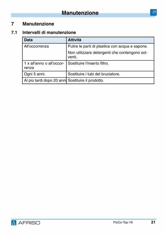
21
Manutenzione IT
FloCo-Top-1K
7 Manutenzione
7.1 Intervalli di manutenzione
Data Attività
All'occorrenza Pulire le parti di plastica con acqua e sapone.
Non utilizzare detergenti che contengono sol-venti.
1 x all'anno o all'occor-renza
Sostituire l'inserto filtro.
Ogni 5 anni. Sostituire i tubi del bruciatore.
Al più tardi dopo 20 anni Sostituire il prodotto.
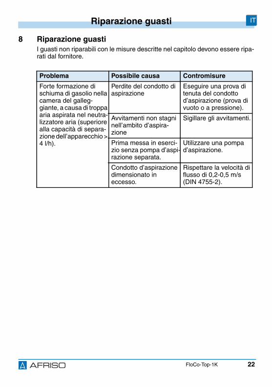
22
Riparazione guasti IT
FloCo-Top-1K
8 Riparazione guastiI guasti non riparabili con le misure descritte nel capitolo devono essere ripa-rati dal fornitore.
Problema Possibile causa Contromisure
Forte formazione dischiuma di gasolio nellacamera del galleg-giante, a causa di troppaaria aspirata nel neutra-lizzatore aria (superiorealla capacità di separa-zione dell’apparecchio >4 l/h).
Perdite del condotto diaspirazione
Eseguire una prova ditenuta del condottod’aspirazione (prova divuoto o a pressione).
Avvitamenti non stagninell’ambito d’aspira-zione
Sigillare gli avvitamenti.
Prima messa in eserci-zio senza pompa d’aspi-razione separata.
Utilizzare una pompad’aspirazione.
Condotto d’aspirazionedimensionato ineccesso.
Rispettare la velocità diflusso di 0,2-0,5 m/s(DIN 4755-2).
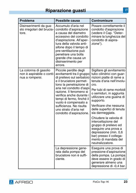
23
Riparazione guasti IT
FloCo-Top-1K
Disinserimenti da gua-sto irregolari del brucia-tore.
Accumulo d’aria nelcondotto d’aspirazionea causa del diametroeccessivo del condottod’aspirazione. All’aper-tura della valvola anti-sifone dopo il tempo dipre-ventilazione puòpenetrare una bollagrande che causa undisinserimento pererrore.
Posare correttamente ilcondotto d'aspirazione(vedere il Cap. "Deter-minare la lunghezza delcondotto di aspira-zione").
La colonna di gasolionon è aspirabile o conti-nua a rompersi.
Piccole perdite degliavvitamenti tra il gruppodi prelievo sul serbatoioe il bruciatore permet-tono la penetrazione diaria nel condotto d’aspi-razione. Il fenomeno siverifica anche durante itempi di fermo, finché ilvuoto è compensato asufficienza. Ne risultauno strato d’aria nelcondotto d’aspirazione.
Sigillare gli avvitamentotubo cilindrici con guar-nizioni piatte di rame atenuta d’aria nell’involu-cro.
Per tubi di rame morbidio semiduri, in aggiuntautilizzare una guaina disupporto.
Verificare che nessunadelle superfici di tenutasia danneggiata.
Chiudere la valvola diintercettazione delgruppo di prelievo edeseguire una prova adepressione (min. 0,6bar) presso il collega-mento di mandata delneutralizzatore.
La depressione gene-rata dalla pompa delbruciatore non è suffi-ciente.
Eseguire una prova dipressione d’aspirazionedella pompa. La pompadeve essere in grado digenerare almeno unadepressione di -0,4 bar.
Problema Possibile causa Contromisure
24
Smontaggio e smaltimento IT
FloCo-Top-1K
9 Smontaggio e smaltimentoSmaltire il prodotto in osservanza delle disposizioni, norme e prescrizioni disicurezza vigenti.
10 Rispedizione al fornitorePrima di rispedire il prodotto, mettetevi in contatto con noi.
11 GaranziaLe informazioni sulla garanzia sono riportate nelle condizioni di contrattogenerali in internet sul sito www.afriso.com o nel vostro contratto d'acquisto.
Altri guasti - Rivolgetevi alla hotlinedi assistenza AFRISO
1. Smontare il prodotto (si veda il Cap. "Montaggio", inordine inverso).
2. Smaltire il prodotto.
Problema Possibile causa Contromisure
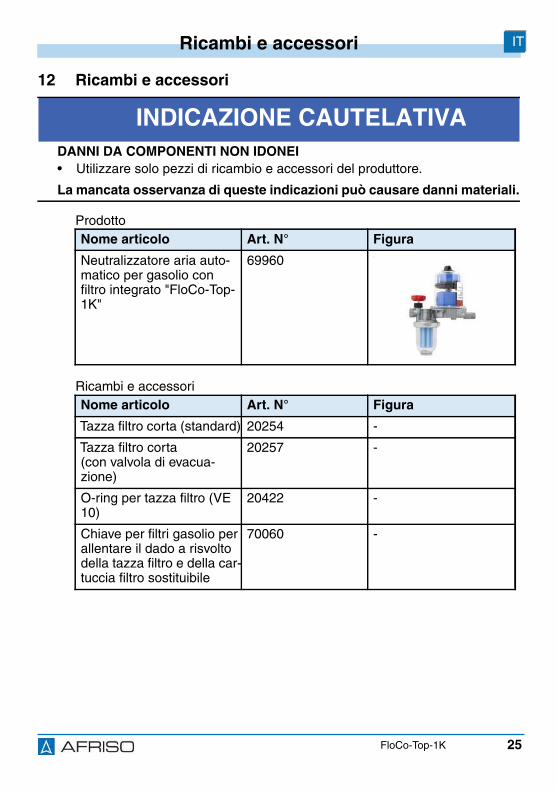
25
Ricambi e accessori IT
FloCo-Top-1K
12 Ricambi e accessori
Prodotto
Ricambi e accessori
INDICAZIONE CAUTELATIVADANNI DA COMPONENTI NON IDONEI• Utilizzare solo pezzi di ricambio e accessori del produttore.
La mancata osservanza di queste indicazioni può causare danni materiali.
Nome articolo Art. N° Figura
Neutralizzatore aria auto-matico per gasolio confiltro integrato "FloCo-Top-1K"
69960 -
Nome articolo Art. N° Figura
Tazza filtro corta (standard) 20254 -
Tazza filtro corta(con valvola di evacua-zione)
20257 -
O-ring per tazza filtro (VE10)
20422 -
Chiave per filtri gasolio perallentare il dado a risvoltodella tazza filtro e della car-tuccia filtro sostituibile
70060 -
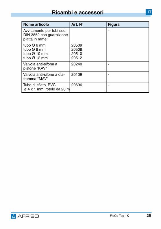
26
Ricambi e accessori IT
FloCo-Top-1K
Avvitamento per tubi sec.DIN 3852 con guarnizionepiatta in rame:
tubo Ø 6 mmtubo Ø 8 mmtubo Ø 10 mmtubo Ø 12 mm
20509205082051020512
-
Valvola anti-sifone apistone "KAV"
20240 -
Valvola anti-sifone a dia-framma "MAV"
20139 -
Tubo di sfiato, PVC,ø 4 x 1 mm, rotolo da 20 m
20696 -
Nome articolo Art. N° Figura
Versión: 12.2016.0ID: 900.000.0287
Lindenstraße 20D-74363 Güglingen
Teléfono +49 7135-102-0Servicio +49 7135-102-211Telefax +49 7135-102-147
Copyright 2016 AFRISO-EURO-INDEX GmbH. Todos los derechos reservados.
BRL A parte 1EN 12514-2
junto con untubo PA 4 x 1 mm
ES
Manual deinstrucciones
Purgador de aire automático para combustiblecon filtro integrado
FloCo-Top-1K
2
Sobre este manual de instrucciones ES
FloCo-Top-1K
1 Sobre este manual de instruccionesEste manual de instrucciones describe el purgador de aire automático paracombustible con filtro integrado "FloCo-Top-1K" (en lo sucesivo también refe-rido como "producto"). Este manual de instrucciones forma parte del pro-ducto.
• No utilice el producto antes de haber leído y entendido este manual deinstrucciones completamente.
• Asegúrese de que el manual de instrucciones siempre está disponiblejunto con el producto para todos los trabajos.
• Pase Usted el manual de instrucciones y todos los documentos que for-men parte del producto a todos los operadores del producto.
• Si opina Usted que el manual de instrucciones contenga errores, contra-dicciones o faltas de claridad, diríjase al fabricante antes de usar el pro-ducto.
Este manual de instrucciones está protegido por derechos de autor, su usose permite únicamente en el marco legal. Se reserva el derecho de modifi-cación.
El fabricante no asume ningún tipo de responsabilidad o garantía por incum-plimiento de este manual de instrucciones así como del incumplimiento delas prescripciones, disposiciones o normas vigentes en el lugar de utilizacióndel producto.
3
Informaciones de seguridad ES
FloCo-Top-1K
2 Informaciones de seguridad
2.1 Advertencias y clases de peligroEste manual de instrucciones comprende advertencias que indican peligrosy riesgos potenciales. Además de las prescripciones contenidas en estemanual de instrucciones se observarán todas las disposiciones, normas eindicaciones de seguridad en el lugar de utilización del producto. Asegúreseante el uso del producto de que se conocen y se observan todas las pres-cripciones, normas e indicaciones de seguridad.
En este manual de instrucciones, las advertencias están marcadas con sím-bolos de y palabras de advertencia. Dependiente de la gravedad de unasituación peligrosa se dividen las advertencias en clases de peligro diferen-tes.
AVISOAVISO indica una situación posiblemente peligrosa que de no evitarse puedecausar daños materiales.

4
Informaciones de seguridad ES
FloCo-Top-1K
2.2 Uso previstoEste producto se emplea exclusivamente en sistemas monotubulares conalimentación de retorno para la purga de aire de los líquidos siguientes eninstalaciones de calentado por combustible:
• Combustible EL según DIN 51603-1- con éster metílico de ácido graso 0-20% (FAME) según EN 14214
• Gasóleo según EN 590- con éster metílico de ácido graso 0-20% (FAME) según EN 14214
Otras aplicaciones no son apropiadas y provocan peligros.
Asegúrese ante el uso del producto de que este producto está adecuadopara el uso previsto por Usted. Exigencia mínima para ello es el cumpli-miento de las siguientes condiciones:
• Todas las disposiciones, normas e indicaciones de seguridad vigentes enel lugar de utilización del producto
• Todas las condiciones y todos los datos especificados del producto
• Condiciones previas para la aplicación prevista por Usted
A parte de ello, lleve a cabo una evaluación de riesgos de la aplicación con-creta y prevista por Usted conforme a un procedimiento reconocido y adoptetodas las medidas de seguridad necesarias conforme al resultado de la eva-luación. Considere también todas las consecuencias posibles de un montajeo de una integración del producto en un sistema o una instalación.
Utilizando este producto realice todos los trabajos únicamente conforme alas condiciones previas especificadas en este manual de instrucciones y enla placa de características así como en concordancia con las disposiciones,normas e indicaciones de seguridad vigentes en el lugar de utilización.
5
Informaciones de seguridad ES
FloCo-Top-1K
2.3 Mal uso razonablemente previsibleEl producto no se aplicará en los siguientes casos y para los fines siguientes:
• Uso con aditivos no diluidos, alcoholes y ácidos
• Uso con sistemas de admisión de presión sin medios de proteccióncorrespondientes
2.4 Calificación del personalTrabajos en y con este producto serán sólo realizados por técnicos especia-lizados que conocen y entienden el contenido de este manual de instruccio-nes y todos los documentos pertenecientes al producto.
A base de su formación especializada, conocimientos y experiencia, los téc-nicos especializados serán capaces de prever y reconocer peligros posiblesque puedan ser causados por el uso del producto.
Los técnicos especializados conocerán todas las disposiciones, normas eindicaciones de seguridad a observar en relación con el producto.
2.5 Equipo de protección individualEmplee siempre el equipo de protección individual requerido. Observe quedurante los trabajos en y con el producto en el lugar de utilización se puedenpresentar peligros que no sean causados directamente por el producto.
2.6 Modificaciones en el productoRealice únicamente tales trabajos en y con el producto que están descritosen el manual de instrucciones. No realice modificaciones no descritas eneste manual de instrucciones.
6
Transporte y almacenaje ES
FloCo-Top-1K
3 Transporte y almacenajeEl producto puede resultar dañado por transporte y almacenaje inadecuado.
AVISODAÑOS DEL PRODUCTO• Asegúrese de que durante el transporte y el almacenaje del producto se
observan las condiciones ambientales especificadas.• Utilice para el transporte el embalaje original.• Almacene el producto sólo en un ambiente seco y limpio.• Asegúrese de que el producto se transporta y almacena a prueba de golpes.
El incumplimiento de estas prescripciones puede causar daños materia-les.
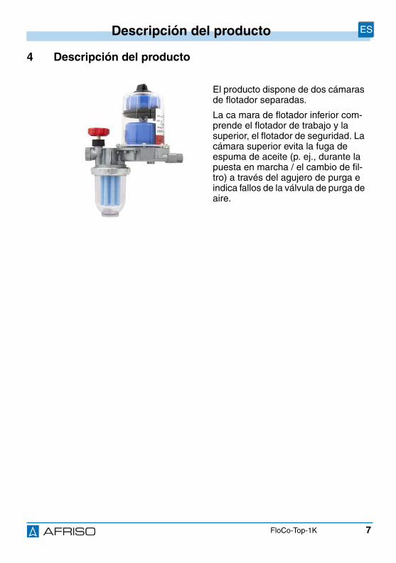
7
Descripción del producto ES
FloCo-Top-1K
4 Descripción del producto
El producto dispone de dos cámarasde flotador separadas.
La ca mara de flotador inferior com-prende el flotador de trabajo y lasuperior, el flotador de seguridad. Lacámara superior evita la fuga deespuma de aceite (p. ej., durante lapuesta en marcha / el cambio de fil-tro) a través del agujero de purga eindica fallos de la válvula de purga deaire.
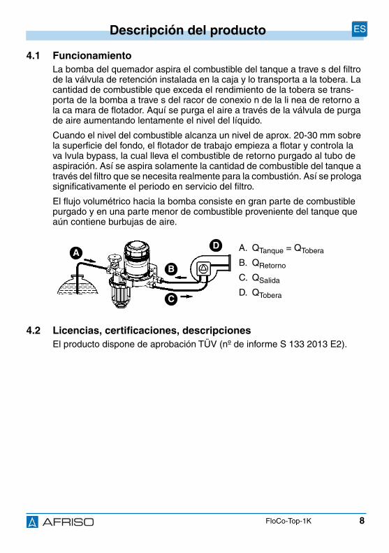
8
Descripción del producto ES
FloCo-Top-1K
4.1 FuncionamientoLa bomba del quemador aspira el combustible del tanque a trave s del filtrode la válvula de retención instalada en la caja y lo transporta a la tobera. Lacantidad de combustible que exceda el rendimiento de la tobera se trans-porta de la bomba a trave s del racor de conexio n de la li nea de retorno ala ca mara de flotador. Aquí se purga el aire a través de la válvula de purgade aire aumentando lentamente el nivel del líquido.
Cuando el nivel del combustible alcanza un nivel de aprox. 20-30 mm sobrela superficie del fondo, el flotador de trabajo empieza a flotar y controla lava lvula bypass, la cual lleva el combustible de retorno purgado al tubo deaspiración. Así se aspira solamente la cantidad de combustible del tanque através del filtro que se necesita realmente para la combustión. Así se prologasignificativamente el periodo en servicio del filtro.
El flujo volumétrico hacia la bomba consiste en gran parte de combustiblepurgado y en una parte menor de combustible proveniente del tanque queaún contiene burbujas de aire.
4.2 Licencias, certificaciones, descripcionesEl producto dispone de aprobación TÜV (nº de informe S 133 2013 E2).
A. QTanque = QTobera
B. QRetorno
C. QSalida
D. QTobera
AD
B
C
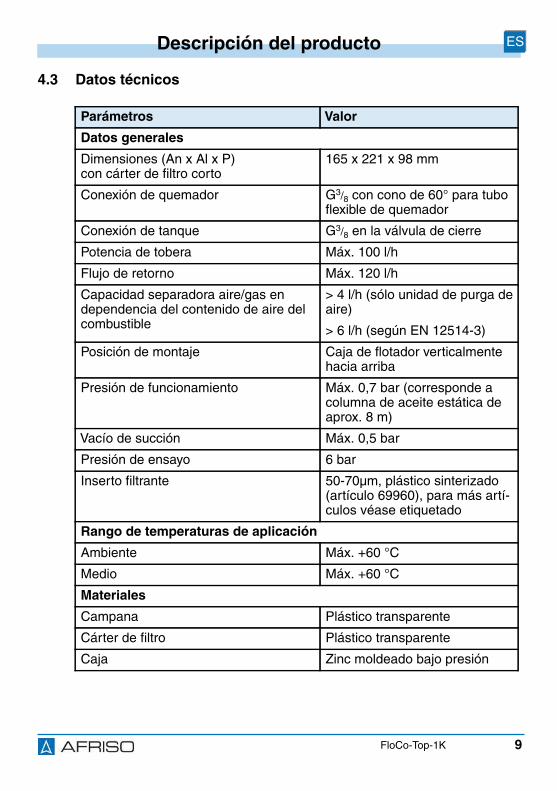
9
Descripción del producto ES
FloCo-Top-1K
4.3 Datos técnicos
Parámetros Valor
Datos generales
Dimensiones (An x Al x P)con cárter de filtro corto
165 x 221 x 98 mm
Conexión de quemador G3/8 con cono de 60° para tuboflexible de quemador
Conexión de tanque G3/8 en la válvula de cierre
Potencia de tobera Máx. 100 l/h
Flujo de retorno Máx. 120 l/h
Capacidad separadora aire/gas endependencia del contenido de aire delcombustible
> 4 l/h (sólo unidad de purga deaire)
> 6 l/h (según EN 12514-3)
Posición de montaje Caja de flotador verticalmentehacia arriba
Presión de funcionamiento Máx. 0,7 bar (corresponde acolumna de aceite estática deaprox. 8 m)
Vacío de succión Máx. 0,5 bar
Presión de ensayo 6 bar
Inserto filtrante 50-70µm, plástico sinterizado(artículo 69960), para más artí-culos véase etiquetado
Rango de temperaturas de aplicación
Ambiente Máx. +60 °C
Medio Máx. +60 °C
Materiales
Campana Plástico transparente
Cárter de filtro Plástico transparente
Caja Zinc moldeado bajo presión
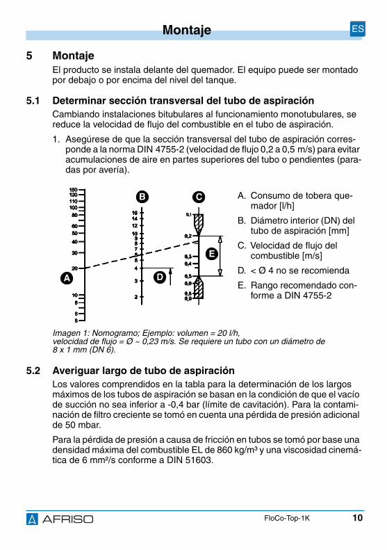
10
Montaje ES
FloCo-Top-1K
5 MontajeEl producto se instala delante del quemador. El equipo puede ser montadopor debajo o por encima del nivel del tanque.
5.1 Determinar sección transversal del tubo de aspiraciónCambiando instalaciones bitubulares al funcionamiento monotubulares, sereduce la velocidad de flujo del combustible en el tubo de aspiración.
1. Asegúrese de que la sección transversal del tubo de aspiración corres-ponde a la norma DIN 4755-2 (velocidad de flujo 0,2 a 0,5 m/s) para evitaracumulaciones de aire en partes superiores del tubo o pendientes (para-das por avería).
5.2 Averiguar largo de tubo de aspiraciónLos valores comprendidos en la tabla para la determinación de los largosmáximos de los tubos de aspiración se basan en la condición de que el vacíode succión no sea inferior a -0,4 bar (límite de cavitación). Para la contami-nación de filtro creciente se tomó en cuenta una pérdida de presión adicionalde 50 mbar.
Para la pérdida de presión a causa de fricción en tubos se tomó por base unadensidad máxima del combustible EL de 860 kg/m³ y una viscosidad cinemá-tica de 6 mm²/s conforme a DIN 51603.
A. Consumo de tobera que-mador [l/h]
B. Diámetro interior (DN) deltubo de aspiración [mm]
C. Velocidad de flujo delcombustible [m/s]
D. < Ø 4 no se recomienda
E. Rango recomendado con-forme a DIN 4755-2
Imagen 1: Nomogramo; Ejemplo: volumen = 20 l/h,velocidad de flujo = Ø ~ 0,23 m/s. Se requiere un tubo con un diámetro de8 x 1 mm (DN 6).
A
CB
D
E

11
Montaje ES
FloCo-Top-1K
5.2.1 Largo del tubo de aspiración máximo con nivel de tanque infe-rior
1. En caso de que el tubo deaspiración esté colocadocomo tubo de aspiracióncon cierre automático,conforme a la reglamenta-ción técnica vigente, qui-tar todas las válvulas deretención delante del pro-ducto.
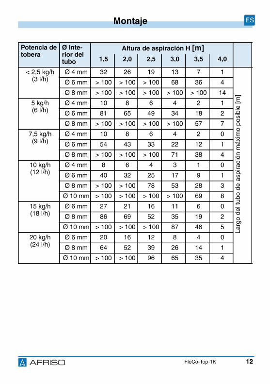
12
Montaje ES
FloCo-Top-1K
Potencia detobera
Ø Inte-rior deltubo
Altura de aspiración H [m]1,5 2,0 2,5 3,0 3,5 4,0
< 2,5 kg/h(3 l/h)
Ø 4 mm 32 26 19 13 7 1
Larg
ode
ltub
ode
aspi
raci
ónm
áxim
opo
sibl
e[m
]
Ø 6 mm > 100 > 100 > 100 68 36 4
Ø 8 mm > 100 > 100 > 100 > 100 > 100 14
5 kg/h(6 l/h)
Ø 4 mm 10 8 6 4 2 1
Ø 6 mm 81 65 49 34 18 2
Ø 8 mm > 100 > 100 > 100 > 100 57 7
7,5 kg/h(9 l/h)
Ø 4 mm 10 8 6 4 2 0
Ø 6 mm 54 43 33 22 12 1
Ø 8 mm > 100 > 100 > 100 71 38 4
10 kg/h(12 l/h)
Ø 4 mm 8 6 4 3 1 0
Ø 6 mm 40 32 25 17 9 1
Ø 8 mm > 100 > 100 78 53 28 3
Ø 10 mm > 100 > 100 > 100 > 100 69 8
15 kg/h(18 l/h)
Ø 6 mm 27 21 16 11 6 0
Ø 8 mm 86 69 52 35 19 2
Ø 10 mm > 100 > 100 > 100 87 46 5
20 kg/h(24 l/h)
Ø 6 mm 20 16 12 8 4 0
Ø 8 mm 64 52 39 26 14 1
Ø 10 mm > 100 > 100 96 65 35 4

13
Montaje ES
FloCo-Top-1K
5.2.2 Largo del tubo de aspiración máximo para el montaje debajodel nivel del tanque
1. Instale una válvula anti-sifón para evitar elvaciado de combustibleen caso de que el tubo deaspiración esté defec-tuoso y el nivel de com-bustible en el tanque estéa un nivel superior.
1 = Válvula anti-sifón conémbolo "KAV"
2 = Válvula anti-sifón con dia-fragma "MAV"
HKAV = Altura de aspiraciónrelevante "KAV"
HMAV = Altura de aspiraciónrelevante "MAV"
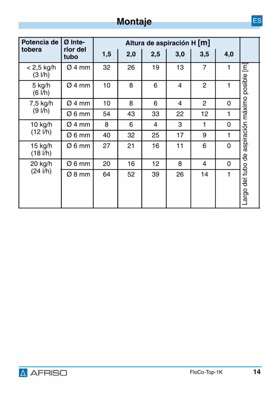
14
Montaje ES
FloCo-Top-1K
Potencia detobera
Ø Inte-rior deltubo
Altura de aspiración H [m]1,5 2,0 2,5 3,0 3,5 4,0
< 2,5 kg/h(3 l/h)
Ø 4 mm 32 26 19 13 7 1
Larg
ode
ltub
ode
aspi
raci
ónm
áxim
opo
sibl
e[m
]
5 kg/h(6 l/h)
Ø 4 mm 10 8 6 4 2 1
7,5 kg/h(9 l/h)
Ø 4 mm 10 8 6 4 2 0
Ø 6 mm 54 43 33 22 12 1
10 kg/h(12 l/h)
Ø 4 mm 8 6 4 3 1 0
Ø 6 mm 40 32 25 17 9 1
15 kg/h(18 l/h)
Ø 6 mm 27 21 16 11 6 0
20 kg/h(24 l/h)
Ø 6 mm 20 16 12 8 4 0
Ø 8 mm 64 52 39 26 14 1

15
Montaje ES
FloCo-Top-1K
5.3 Montar producto Asegúrese de que no se exceda la temperatura ambiental admitida.
Asegúrese de que el producto no sea montado en una parte de la calderano aislada o en su cercanía, por encima de tapas a abrir en puntos decombustión o en el canal de humos.
Asegúrese de que la caja de flotador se posiciona verticalmente haciaarriba.
1. Fije el producto utilizandoel soporte adjunto y loscuatro tornillos perforado-res en el revestimiento dela caldera.
2. Utilice el soporte comoplantilla para enroscar lostornillos perforadores. Laflecha (A) apuntará haciaarriba.
AVISOPÉRDIDAS EN EL PRODUCTO
No emplee cáñamo o cinta de teflon para el sellado.• Asegúrese de que sellando una unión roscada de tubo según DIN 3852 se
emplea una rosca cilíndrica (rosca G) y que se sella ésta con junta plana opegamento adecuado.
El incumplimiento de estas prescripciones puede causar daños materia-les.
A
16
Montaje ES
FloCo-Top-1K
3. Selle el tubo de aspiración en la rosca interior G3/8 de la caja con uniónroscada cilíndrica para tubo G3/8 según DIN 3852.
4. Emplee un manguito de soporte en caso de tubos de cobre suave o semi-duro.
5. Aguante con llave abierta (SW 24) y apriete la unión roscada para tuboen el racor de conexión.
6. Monte los tubos flexibles de quemador. Durante el montaje, mantenga lassuperficies de sellado limpias e intactas.
5.4 Prueba de presiónPara la prueba de presión del tubo de aspiración no conecte la presión en elproducto porque la válvula de retención integrada en el producto no permitela transmisión de presión al tubo de aspiración.
1. No incluya el producto en la prueba de presión.
AVISODAÑOS DEL PRODUCTO• Asegúrese de que no se confundan las conexiones de salida y de retorno.
El incumplimiento de estas prescripciones puede causar daños materia-les.

17
Montaje ES
FloCo-Top-1K
5.5 Pérdida de presiónEl producto permite la instalación de diferentes insertos filtrantes. Las pérdi-das de presión resultantes de ello se obtienen del diagrama.
5.5.1 Funcionamiento de aspiración con inserto filtrante limpio
5.5.2 Funcionamiento de aspiración con inserto filtrante contami-nado al 50 %
A. Inserto de plástico sinteri-zado 35 µm
B. Inserto de plástico sinteri-zado 70 µm
C. Fieltro
D. Criba de acero
1. Inserto de plástico sinteri-zado 35 µm
2. Inserto de plástico sinteri-zado 70 µm
3. Fieltro
4. Criba de acero
Paso Q [l/h]
Pér
dida
depr
esió
np
[mba
r]
A
B
DC
Paso [l/h]
Pér
dida
depr
esió
np
[mba
r] A
B
DC
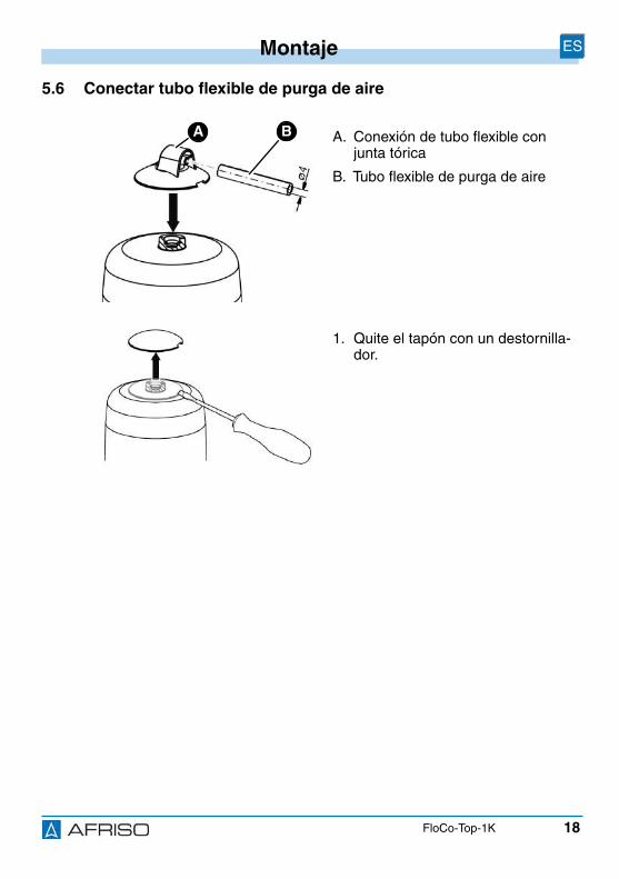
18
Montaje ES
FloCo-Top-1K
5.6 Conectar tubo flexible de purga de aire
A. Conexión de tubo flexible conjunta tórica
B. Tubo flexible de purga de aire
1. Quite el tapón con un destornilla-dor.
BA
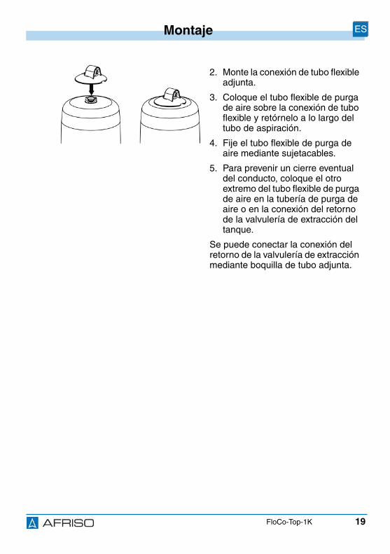
19
Montaje ES
FloCo-Top-1K
2. Monte la conexión de tubo flexibleadjunta.
3. Coloque el tubo flexible de purgade aire sobre la conexión de tuboflexible y retórnelo a lo largo deltubo de aspiración.
4. Fije el tubo flexible de purga deaire mediante sujetacables.
5. Para prevenir un cierre eventualdel conducto, coloque el otroextremo del tubo flexible de purgade aire en la tubería de purga deaire o en la conexión del retornode la valvulería de extracción deltanque.
Se puede conectar la conexión delretorno de la valvulería de extracciónmediante boquilla de tubo adjunta.
20
Funcionamiento ES
FloCo-Top-1K
6 Funcionamiento
6.1 Nivel de combustible en la caja de flotadorEl nivel de combustible depende de las condiciones de funcionamiento de lainstalación y varía en el modo de aspiración entre aprox. 20-50 mm. Si elnivel de combustible es más alto y el tubo de aspiración está colocado sinpérdidas, la caja del flotador se puede llenar completamente de combustible.La causa de este efecto es la absorción del aire por el combustible. Esteefecto provoca la degradación de la capa de aire. Cuando se cambian lascondiciones de funcionamiento, p. ej., a causa de un nivel de líquido dismi-nuyendo en el tanque, se vuelve a crear una capa de aire en la caja del flo-tador.
6.2 Régimen de presiónYa que en el régimen de presión no se presentan desgasificaciones por aspi-ración, no es razonable emplear el producto. Emplee en el régimen de pre-sión un filtro monotubular con admisión de retorno. Si por el tipo de instala-ción se requiere un purgador de aire para combustible,se puede emplear un "Flow-Control 3/K HT" precedido de un filtro y un cárterde filtro de latón o cartucho de filtro recambiable.
Asegúrese de que tome las precauciones apropiadas para esta aplica-ción para evitar, incluso en un caso de avería (regulador de presión defec-tuoso), el exceso de la presión previa máxima admisible de 0,7 bar (p. ej.,con una válvula de rebose, un interruptor de presión).
Asegúrese de que se posiciona un cubeto de retención debajo de lostubos de quemador y del purgador de aire para combustible, sobre el cualse hacen detectar pérdidas de combustible y se realiza la parada del que-mador.
21
Funcionamiento ES
FloCo-Top-1K
6.3 Acumulaciones de aire en el cárter de filtroSegún tipo del inserto filtrante y de la presión de aspiración del sistema, elinserto filtrante puede retener más o menos aire separado del combustible.
En el tamiz del filtro se puede formar una capa de aire visible en el cárter defiltro. El tamaño de la capa de aire depende de la velocidad de flujo y de lapresión de aspiración en el filtro, es decir: un caudal más grande arrastramás partículas de aire por el tamiz que una velocidad de flujo menor (escasoconsumo de combustible en el quemador). De ello resulta que en los tiemposde trabajo del quemador, en los que se forma un vacío, se reduce el nivel decombustible en el cárter de filtro fuera del tamiz. El interior del tamiz está lle-nado completamente de combustible filtrado, así que no se pueden presen-tar fallos. La estructura de poros irregular con efecto espacial del inserto fil-trante de plástico sinterizado estándar facilita una muy buena permeabilidaddel aire.
6.4 Empleo en zonas con peligro de inundaciónEl producto es apto para zonas con peligro de inundación y resistente a lapresión del agua hasta una columna de agua de 10 m (1 bar presión exte-rior).
AVISOPRODUCTO INOPERATIVO• Asegúrese de que se recambia el producto después de una inundación.
El incumplimiento de estas prescripciones puede causar daños materia-les.
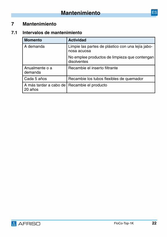
22
Mantenimiento ES
FloCo-Top-1K
7 Mantenimiento
7.1 Intervalos de mantenimiento
Momento Actividad
A demanda Limpie las partes de plástico con una lejía jabo-nosa acuosa
No emplee productos de limpieza que contengandisolventes
Anualmente o ademanda
Recambie el inserto filtrante
Cada 5 años Recambie los tubos flexibles de quemador
A más tardar a cabo de20 años
Recambie el producto
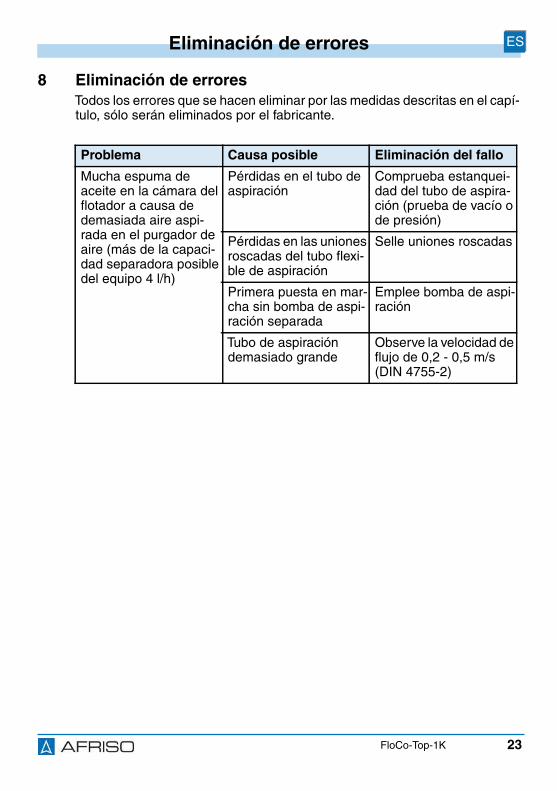
23
Eliminación de errores ES
FloCo-Top-1K
8 Eliminación de erroresTodos los errores que se hacen eliminar por las medidas descritas en el capí-tulo, sólo serán eliminados por el fabricante.
Problema Causa posible Eliminación del fallo
Mucha espuma deaceite en la cámara delflotador a causa dedemasiada aire aspi-rada en el purgador deaire (más de la capaci-dad separadora posibledel equipo 4 l/h)
Pérdidas en el tubo deaspiración
Comprueba estanquei-dad del tubo de aspira-ción (prueba de vacío ode presión)
Pérdidas en las unionesroscadas del tubo flexi-ble de aspiración
Selle uniones roscadas
Primera puesta en mar-cha sin bomba de aspi-ración separada
Emplee bomba de aspi-ración
Tubo de aspiracióndemasiado grande
Observe la velocidad deflujo de 0,2 - 0,5 m/s(DIN 4755-2)
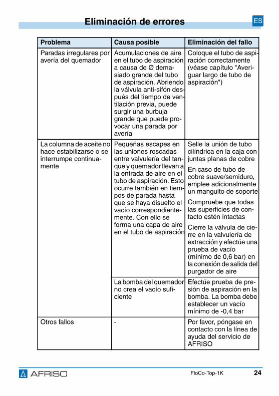
24
Eliminación de errores ES
FloCo-Top-1K
Paradas irregulares poravería del quemador
Acumulaciones de aireen el tubo de aspiracióna causa de Ø dema-siado grande del tubode aspiración. Abriendola válvula anti-sifón des-pués del tiempo de ven-tilación previa, puedesurgir una burbujagrande que puede pro-vocar una parada poravería
Coloque el tubo de aspi-ración correctamente(véase capítulo "Averi-guar largo de tubo deaspiración")
La columna de aceite nohace estabilizarse o seinterrumpe continua-mente
Pequeñas escapes enlas uniones roscadasentre valvulería del tan-que y quemador llevan ala entrada de aire en eltubo de aspiración. Estoocurre también en tiem-pos de parada hastaque se haya disuelto elvacío correspondiente-mente. Con ello seforma una capa de aireen el tubo de aspiración
Selle la unión de tubocilíndrica en la caja conjuntas planas de cobre
En caso de tubo decobre suave/semiduro,emplee adicionalmenteun manguito de soporte
Compruebe que todaslas superficies de con-tacto estén intactas
Cierre la válvula de cie-rre en la valvulería deextracción y efectúe unaprueba de vacío(mínimo de 0,6 bar) enla conexión de salida delpurgador de aire
La bomba del quemadorno crea el vacío sufi-ciente
Efectúe prueba de pre-sión de aspiración en labomba. La bomba debeestablecer un vacíomínimo de -0,4 bar
Otros fallos - Por favor, póngase encontacto con la línea deayuda del servicio deAFRISO
Problema Causa posible Eliminación del fallo
25
Puesta fuera de servicio y eliminación de residuos ES
FloCo-Top-1K
9 Puesta fuera de servicio y eliminación de residuosElimine el producto conforme a las disposiciones, normas e indicaciones deseguridad vigentes.
10 ReexpediciónAnte la reexpedición del producto, póngase en contacto con nosotros.
11 GarantíaPara informaciones acerca de la garantía, consulte nuestras CondicionesGenerales en Internet bajo www.afriso.com o en el contrato de compraventa.
1. Desmonte el producto (véase capítulo "Montaje" enorden inverso).
2. Elimine el producto.

26
Piezas de repuesto y accesorios ES
FloCo-Top-1K
12 Piezas de repuesto y accesorios
Producto
Piezas de repuesto y accesorios
AVISODAÑOS POR PIEZAS INAPROPIADAS• Emplee únicamente piezas de repuesto y accesorios del fabricante.
El incumplimiento de estas prescripciones puede causar daños materia-les.
Denominación de artí-culo
Nº art. Imagen
Purgador de aire automá-tico con filtro integrado"FloCo-Top-1K"
69960 -
Denominación de artí-culo
Nº art. Imagen
Cárter de filtro corto (están-dar)
20254 -
Cárter de filtro corto(con dispositivo de vaciado)
20257 -
Junta plana para cárter defiltro (VE: 10)
20422 -
Llave de filtro de aceitepara soltar la tuerca deunión del recipiente filtrantey del cartucho de filtro decambio
70060 -

27
Piezas de repuesto y accesorios ES
FloCo-Top-1K
Unión roscada de tubosegún DIN 3852 con juntaplana de cobre:
tubo Ø 6 mmtubo Ø 8 mmtubo Ø 10 mmtubo Ø 12 mm
20509205082051020512
-
Válvula anti-sifón conémbolo "KAV"
20240 -
Válvula anti-sifón con dia-fragma "MAV"
20139 -
Tubo flexiblede purga de aire, PVC, Ø 4x 1 mm, rollo de 20 m
20696 -
Denominación de artí-culo
Nº art. Imagen
Wersja: 12.2016.0ID: 900.000.0287
Lindenstraße 2074363 Güglingen
telefon +49 7135-102-0serwis +49 7135-102-211
telefaks +49 [email protected]
Copyright 2016 AFRISO-EURO-INDEX GmbH. Wszystkie prawa zastrze one.
BRL A cz 1EN 12514-2
w powi zaniu zw em poliamidowym 4 x 1 mm
PL
Instrukcjaeksploatacji
Automatyczny odpowietrznik oleju opałowegozintegrowany z filtrem
FloCo-Top-1K

2
Objaśnienia do niniejszej instrukcji eksploatacji PL
FloCo-Top-1K
1 Objaśnienia do niniejszej instrukcji eksploatacjiNiniejsza instrukcja eksploatacji opisuje automatyczny odpowietrznik oleju opałowego zintegrowany z filtrem o nazwie „FloCo-Top-1K” (poniżej zwany także produktem). Niniejsza instrukcja eksploatacji jest częścią produktu.
• Produkt wolno użytkować dopiero po całkowitym przeczytaniu i pełnym zrozumieniu instrukcji eksploatacji.
• Należy upewnić się, że instrukcja eksploatacji jest dostępna w każdej chwili podczas prac wykonywanych przy produkcie oraz z jego pomocą.
• Należy przekazać instrukcję eksploatacji oraz wszystkie dokumenty należące do produktu wszystkim użytkownikom produktu.
• W razie wystąpienia opinii, że instrukcja eksploatacji zawiera błędy, sprzeczności lub niejasności, należy skontaktować się z producentem przed oddaniem produktu do użytkowania.
Niniejsza instrukcja eksploatacji jest chroniona prawem autorskim, wobec czego wolno ją stosować wyłącznie w ramach obowiązującego prawa. Zmiany zastrzeżone.
Producent nie przejmuje żadnej odpowiedzialności lub gwarancji za uszko-dzenia lub ich konsekwencje wynikające z nieprzestrzegania niniejszej instrukcji eksploatacji oraz przepisów, warunków i norm obowiązujących w miejscu użytkowania produktu.
3
Informacje na temat bezpieczeństwa PL
FloCo-Top-1K
2 Informacje na temat bezpieczeństwa
2.1 Wskazówki ostrzegawcze i klasy zagro eniaNiniejsza instrukcja eksploatacji zawiera wskazówki ostrzegawcze zwraca-j ce uwag na potencjalne zagro enia oraz ryzyka. Poza zaleceniami zawar-tymi w niniejszej instrukcji eksploatacji trzeba przestrzega wszystkichwarunków, norm oraz przepisów bezpiecze stwa obowi zuj cych w miejscuu ytkowania produktu. Przed zastosowaniem produktu nale y upewni si ,e wszystkie warunki, normy oraz przepisy bezpiecze stwa s u ytkowni-kowi znane i przestrzegane.
Wskazówki ostrzegawcze s oznakowane w niniejszej instrukcji eksploatacjiza pomoc symboli ostrzegawczych oraz haseł ostrzegawczych. Wskazówkiostrzegawcze s podzielone na ró ne klasy zagro enia w zale no ci odstopnia ci ko ci sytuacji zagro enia.
WSKAZÓWKAWSKAZÓWKA zwraca uwagę na ewentualnie niebezpieczną sytuację, która w przypadku nieprzestrzegania może spowodować powstanie szkód material-nych.
4
Informacje na temat bezpieczeństwa PL
FloCo-Top-1K
2.2 Stosowanie zgodne z przeznaczeniemTen produkt przeznaczony jest wyłącznie do stosowania w instalacjach jed-norurowych z doprowadzeniem strumienia powrotnego i służy w instala-cjach opalanych olejem do odpowietrzania w trybie ciągłym następujących cieczy:
• oleju opałowego EL według normy DIN 51603-1- zawierającego 0 - 20 % estrów metylowych kwasów tłuszczowych
(FAME) zgodnie z normą EN 14214,
• oleju napędowego według normy EN 590- zawierającego 0 - 20 % estrów metylowych kwasów tłuszczowych
(FAME) zgodnie z normą EN 14214.
Inny rodzaj zastosowania nie jest zgodny z przeznaczeniem i powoduje powstawanie zagrożeń.
Przed zastosowaniem produktu należy upewnić się, że produkt nadaje się do przewidzianego przez użytkownika rodzaju zastosowania. W tym celu trzeba uwzględnić co najmniej następujące wymogi:
• wszystkie warunki, normy oraz przepisy bezpieczeństwa obowiązujące w miejscu użytkowania produktu,
• wszystkie warunki i dane przewidziane w specyfikacji produktu,
• warunki przewidziane dla planowanego przez użytkownika zastosowa-nia.
Ponadto należy przeprowadzić według uznanej procedury ocenę ryzyka w odniesieniu do konkretnego zastosowania przewidzianego przez użytkow-nika oraz podjąć wszelkie odpowiednie działania na rzecz bezpieczeństwa zgodnie z wynikiem procedury oceny ryzyka. Należy też przy tym uwzględ-nić możliwe konsekwencje wynikające z zabudowy lub integracji produktu w systemie lub instalacji.
Podczas użytkowania produktu wszystkie prace należy przeprowadzać wyłącznie w warunkach wyszczególnionych w instrukcji eksploatacji oraz na tabliczce znamionowej, w ramach danych technicznych zawartych w spe-cyfikacji oraz w zgodzie ze wszystkimi warunkami, normami i przepisami bezpieczeństwa obowiązującymi w miejscu użytkowania produktu.
5
Informacje na temat bezpieczeństwa PL
FloCo-Top-1K
2.3 Przewidywalne błędne stosowanie
Produktu nie wolno stosować w szczególności w następujących przypad-kach i do następujących celów:
• w kontakcie z nierozcieńczonymi dodatkami uszlachetniającymi, alkoho-lami i kwasami,
• w układach ciśnieniowych bez odpowiednich zabezpieczeń.
2.4 Kwalifikacje personelu
Czynności wykonywane przy produkcie oraz z jego pomocą mogą wykony-wać wyłącznie wykwalifikowani pracownicy, którzy zapoznali się z niniejszą instrukcją eksploatacji oraz ze wszystkimi dokumentami należącymi do pro-duktu i zrozumieli ich treść.
Ze względu na swoje wykształcenie zawodowe, wiedzę i doświadczenia pracownicy wykwalifikowani muszą być w stanie przewidzieć i rozpoznać możliwe zagrożenia, które mogą powstawać z tytułu użytkowania produktu.
Pracownikom wykwalifikowanym muszą być znane wszystkie obowiązujące warunki, normy i przepisy bezpieczeństwa, których należy przestrzegać podczas czynności wykonywanych przy produkcie oraz z jego pomocą.
2.5 Osobiste wyposażenie ochronne
Należy zawsze stosować wymagane osobiste wyposażenie ochronne. Pod-czas czynności wykonywanych przy produkcie oraz z jego pomocą należy także uwzględnić, że w miejscu użytkowania mogą występować zagrożenia, których źródłem nie jest bezpośrednio sam produkt.
2.6 Modyfikacje produktu
Przy produkcie oraz z jego pomocą należy wykonywać wyłącznie takie czynności, które są opisane w niniejszej instrukcji eksploatacji. Nie wolno wprowadzać zmian, które nie są opisane w niniejszej instrukcji eksploatacji.
6
Transport i składowanie PL
FloCo-Top-1K
3 Transport i składowanieNiewłaściwy transport i składowanie mogą spowodować uszkodzenie pro-duktu.
WSKAZÓWKA
USZKODZENIE PRODUKTU
• Należy upewnić się, że podczas transportu i składowania produktu dotrzy-mywane są warunki otoczenia wyszczególnione w specyfikacji.
• Do celów transportowych należy wykorzystywać oryginalne opakowanie.
• Produkt należy przechowywać wyłącznie w suchym i czystym otoczeniu.
• Należy upewnić się, że podczas transportu i składowania produkt jest chro-niony przed uderzeniami.
Nieprzestrzeganie niniejszych zaleceń może doprowadzić do powstania szkód materialnych.
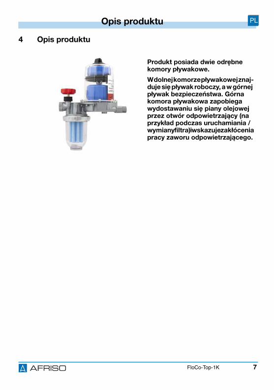
7
Opis produktu PL
FloCo-Top-1K
4 Opis produktu
Produkt posiada dwie odrębne komory pływakowe.
W dolnej komorze pływakowej znaj-duje się pływak roboczy, a w górnej pływak bezpieczeństwa. Górna komora pływakowa zapobiega wydostawaniu się piany olejowej przez otwór odpowietrzający (na przykład podczas uruchamiania / wymiany filtra) i wskazuje zakłócenia pracy zaworu odpowietrzającego.
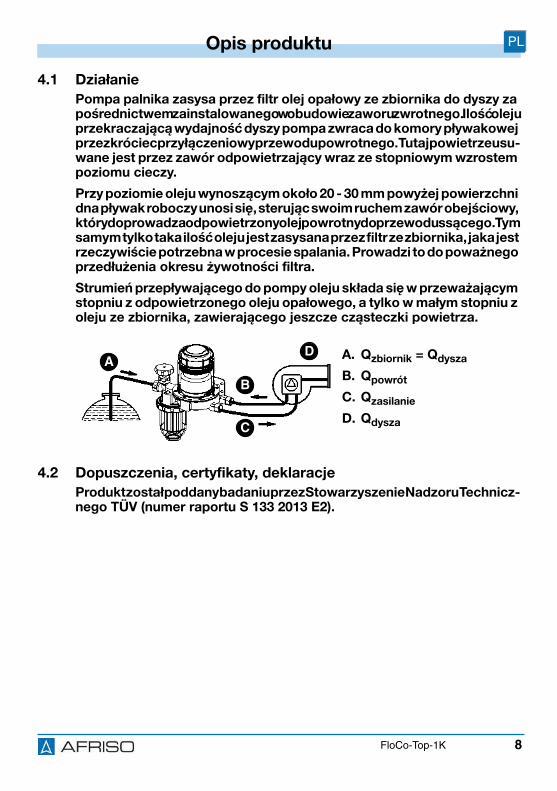
8
Opis produktu PL
FloCo-Top-1K
4.1 Działanie
Pompa palnika zasysa przez filtr olej opałowy ze zbiornika do dyszy za pośrednictwem zainstalowanego w obudowie zaworu zwrotnego. Ilość oleju przekraczającą wydajność dyszy pompa zwraca do komory pływakowej przez króciec przyłączeniowy przewodu powrotnego. Tutaj powietrze usu-wane jest przez zawór odpowietrzający wraz ze stopniowym wzrostem poziomu cieczy.
Przy poziomie oleju wynoszącym około 20 - 30 mm powyżej powierzchni dna pływak roboczy unosi się, sterując swoim ruchem zawór obejściowy, który doprowadza odpowietrzony olej powrotny do przewodu ssącego. Tym samym tylko taka ilość oleju jest zasysana przez filtr ze zbiornika, jaka jest rzeczywiście potrzebna w procesie spalania. Prowadzi to do poważnego przedłużenia okresu żywotności filtra.
Strumień przepływającego do pompy oleju składa się w przeważającym stopniu z odpowietrzonego oleju opałowego, a tylko w małym stopniu z oleju ze zbiornika, zawierającego jeszcze cząsteczki powietrza.
4.2 Dopuszczenia, certyfikaty, deklaracje
Produkt został poddany badaniu przez Stowarzyszenie Nadzoru Technicz-nego TÜV (numer raportu S 133 2013 E2).
A. Qzbiornik = Qdysza
B. Qpowrót
C. Qzasilanie
D. Qdysza
AD
B
C

9
Opis produktu PL
FloCo-Top-1K
4.3 Dane techniczne
Parametr Wartość
Dane ogólne
wymiary (szerokość x wysokość x głębokość)z krótkim naczyniem filtra
165 x 221 x 98 mm
przyłącze palnika G3/8 stożkowe 60° do podłącze-nia przewodu palnika
przyłącze zbiornika G3/8 na zaworze odcinającym
wydajność dyszy maksymalnie 100 l/h
przepływ powrotny maksymalnie 120 l/h
wydajność odpowietrzania separatora powietrza / gazu, w zależności od zawar-tości powietrza w paliwie
> 4 l/h (tylko zespół odpowie-trzania)
> 6 l/h (według normy EN 12514-3)
pozycja montażowa obudowa pływaka pionowo w kierunku górnym
nadciśnienie robocze maksymalnie 0,7 bar (odpowia-dające statycznemu słupowi oleju o wysokości około 8 m)
podciśnienie ssania maksymalnie 0,5 bar
ciśnienie próbne 6 bar
wkład filtra 50 - 70μm, sztuczne tworzywo spiekane (artykuł 69960), pozo-stałe artykuły patrz etykieta na opakowaniu
Dopuszczalny zakres temperatur
otoczenie maksymalnie +60 °
czynnik maksymalnie +60 °
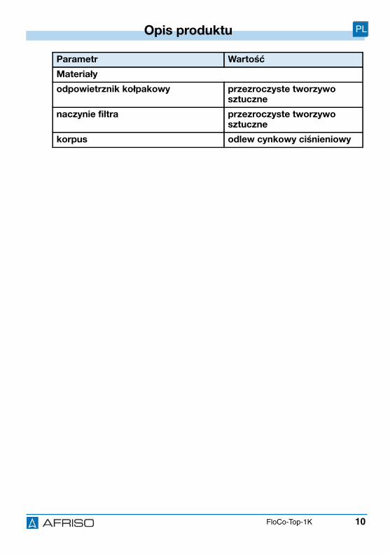
10
Opis produktu PL
FloCo-Top-1K
Materiały
odpowietrznik kołpakowy przezroczyste tworzywo sztuczne
naczynie filtra przezroczyste tworzywo sztuczne
korpus odlew cynkowy ciśnieniowy
Parametr Wartość
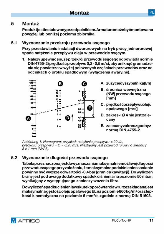
11
Montaż PL
FloCo-Top-1K
5 Montaż Produkt jest instalowany przed palnikiem. Armatura może być montowana powyżej lub poniżej poziomu zbiornika.
5.1 Wyznaczanie przekroju przewodu ssącego
Przy przestawianiu instalacji dwururowych na tryb pracy jednorurowej spada natężenie przepływu oleju w przewodzie ssącym.
1. Należy upewnić się, że przekrój przewodu ssącego odpowiada normie DIN 4755-2 (prędkość przepływu 0,2 - 0,5 m/s), aby uniknąć gromadze-nia się powietrza w wyżej położonych częściach przewodów oraz na odcinkach o profilu spadkowym (wyłączenia awaryjne).
5.2 Wyznaczanie długości przewodu ssącego
Tabela przeznaczona jest do wyznaczania maksymalnie możliwej długości przewodu ssącego przy założeniu, że maksymalne podciśnienie ssania nie powinno być wyższe od wartości -0,4 bar (granica kawitacji). Do wyliczeń brany jest pod uwagę dodatkowy spadek ciśnienia na poziomie 50 mbar, wynikający z występującego zanieczyszczenia filtra.
Do wyliczeń spadku ciśnienia wskutek oporów tarcia w rurze zakładana jest maksymalna gęstość oleju opałowego EL na poziomie 860 kg/m³ oraz lep-kość kinematyczna na poziomie 6 mm²/s zgodnie z normą DIN 51603.
A. zużycie dyszy palnika [l/h]
B. średnica wewnętrzna (NW) przewodu ssącego [mm]
C. prędkość przepływu oleju opałowego [m/s]
D. zakres < Ø 4 nie jest zale-cany
E. zalecany zakres zgodny z normą DIN 4755-2
Abbildung 1: Nomogram; przykład: natężenie przepływu = 20 l/h, prędkość przepływu = Ø ~ 0,23 m/s. Niezbędny jest przewód rurowy o średnicy 8 x 1 mm (NW 6).
A
CB
D
E
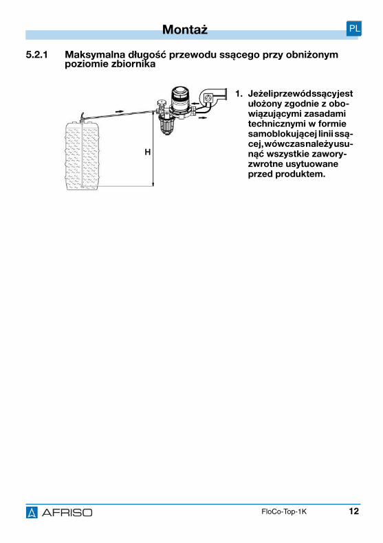
12
Montaż PL
FloCo-Top-1K
5.2.1 Maksymalna długość przewodu ssącego przy obniżonym poziomie zbiornika
1. Jeżeli przewód ssący jest ułożony zgodnie z obo-wiązującymi zasadami technicznymi w formie samoblokującej linii ssą-cej, wówczas należy usu-nąć wszystkie zawory-zwrotne usytuowane przed produktem.
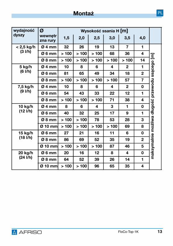
13
Montaż PL
FloCo-Top-1K
wydajność dyszy
Ø wewnętrzna rury
Wysokość ssania H [m]
1,5 2,0 2,5 3,0 3,5 4,0
< 2,5 kg/h(3 l/h)
Ø 4 mm 32 26 19 13 7 1
ma
ksym
aln
ie m
ożliw
a dłu
gość
prz
ew
od
u s
są
ce
go
[m
]Ø 6 mm > 100 > 100 > 100 68 36 4
Ø 8 mm > 100 > 100 > 100 > 100 > 100 14
5 kg/h(6 l/h)
Ø 4 mm 10 8 6 4 2 1
Ø 6 mm 81 65 49 34 18 2
Ø 8 mm > 100 > 100 > 100 > 100 57 7
7,5 kg/h(9 l/h)
Ø 4 mm 10 8 6 4 2 0
Ø 6 mm 54 43 33 22 12 1
Ø 8 mm > 100 > 100 > 100 71 38 4
10 kg/h(12 l/h)
Ø 4 mm 8 6 4 3 1 0
Ø 6 mm 40 32 25 17 9 1
Ø 8 mm > 100 > 100 78 53 28 3
Ø 10 mm > 100 > 100 > 100 > 100 69 8
15 kg/h(18 l/h)
Ø 6 mm 27 21 16 11 6 0
Ø 8 mm 86 69 52 35 19 2
Ø 10 mm > 100 > 100 > 100 87 46 5
20 kg/h(24 l/h)
Ø 6 mm 20 16 12 8 4 0
Ø 8 mm 64 52 39 26 14 1
Ø 10 mm > 100 > 100 96 65 35 4
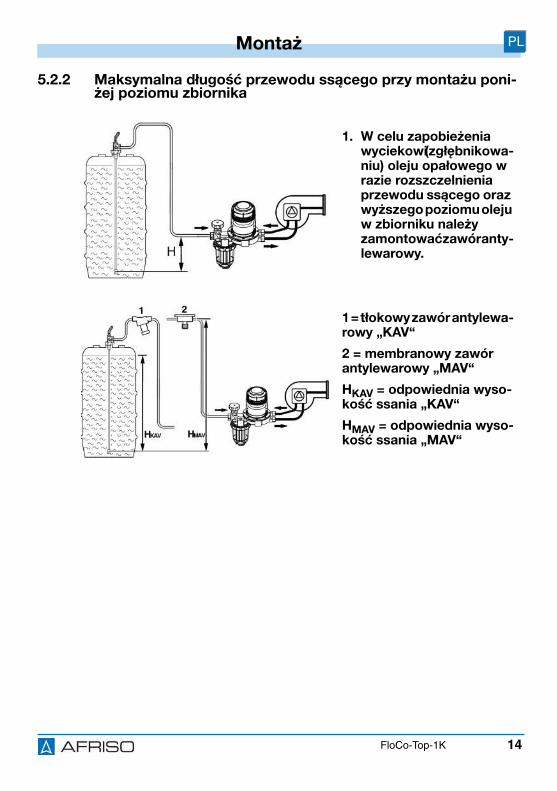
14
Montaż PL
FloCo-Top-1K
5.2.2 Maksymalna długość przewodu ssącego przy montażu poni-żej poziomu zbiornika
1. W celu zapobieżenia wyciekowi (zgłębnikowa-niu) oleju opałowego w razie rozszczelnienia przewodu ssącego oraz wyższego poziomu oleju w zbiorniku należy zamontować zawór anty-lewarowy.
1 = tłokowy zawór antylewa-rowy „KAV“
2 = membranowy zawór antylewarowy „MAV“
HKAV = odpowiednia wyso-kość ssania „KAV“
HMAV = odpowiednia wyso-kość ssania „MAV“
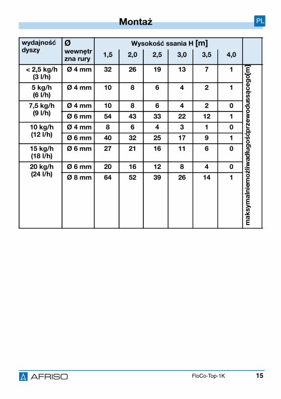
15
Montaż PL
FloCo-Top-1K
wydajność dyszy
Ø wewnętrzna rury
Wysokość ssania H [m]
1,5 2,0 2,5 3,0 3,5 4,0
< 2,5 kg/h(3 l/h)
Ø 4 mm 32 26 19 13 7 1
ma
ksym
aln
ie m
ożliw
a dłu
gość
prz
ew
od
u ssą
ce
go
[m]
5 kg/h(6 l/h)
Ø 4 mm 10 8 6 4 2 1
7,5 kg/h(9 l/h)
Ø 4 mm 10 8 6 4 2 0
Ø 6 mm 54 43 33 22 12 1
10 kg/h(12 l/h)
Ø 4 mm 8 6 4 3 1 0
Ø 6 mm 40 32 25 17 9 1
15 kg/h(18 l/h)
Ø 6 mm 27 21 16 11 6 0
20 kg/h(24 l/h)
Ø 6 mm 20 16 12 8 4 0
Ø 8 mm 64 52 39 26 14 1
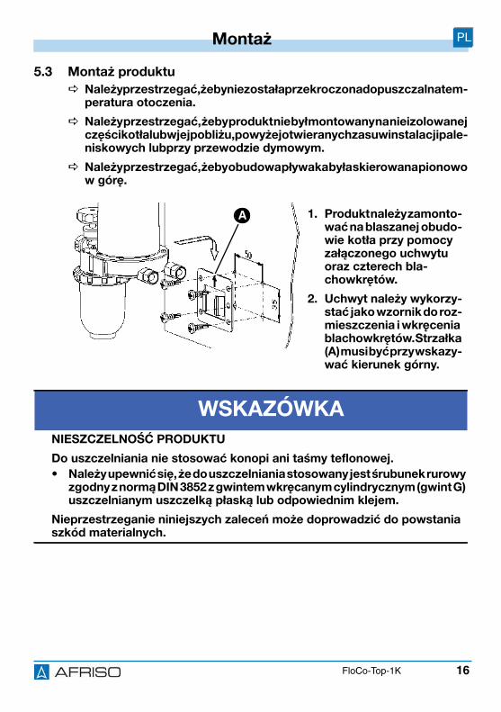
16
Montaż PL
FloCo-Top-1K
5.3 Montaż produktu
Należy przestrzegać, żeby nie została przekroczona dopuszczalna tem-peratura otoczenia.
Należy przestrzegać, żeby produkt nie był montowany na nieizolowanej części kotła lub w jej pobliżu, powyżej otwieranych zasuw instalacji pale-niskowych lubprzy przewodzie dymowym.
Należy przestrzegać, żeby obudowa pływaka była skierowana pionowo w górę.
1. Produkt należy zamonto-wać na blaszanej obudo-wie kotła przy pomocy załączonego uchwytu oraz czterech bla-chowkrętów.
2. Uchwyt należy wykorzy-stać jako wzornik do roz-mieszczenia i wkręcenia blachowkrętów. Strzałka (A) musi być przy wskazy-wać kierunek górny.
WSKAZÓWKA
NIESZCZELNOŚĆ PRODUKTU
Do uszczelniania nie stosować konopi ani taśmy teflonowej.
• Należy upewnić się, że do uszczelniania stosowany jest śrubunek rurowy zgodny z normą DIN 3852 z gwintem wkręcanym cylindrycznym (gwint G) uszczelnianym uszczelką płaską lub odpowiednim klejem.
Nieprzestrzeganie niniejszych zaleceń może doprowadzić do powstania szkód materialnych.
A
17
Montaż PL
FloCo-Top-1K
3. Uszczelnić przewód ssący w gwincie wewnętrznym G3/8 obudowy śru-
bunkiem rurowym z gwintem cylindrycznym G3/8 zgodnie z normą DIN 3852 .
4. W razie stosowania rury miedzianej miękkiej lub półtwardej użyć tulei wzmacniającej.
5. Przytrzymać kluczem widełkowym (SW 24) i dokręcić śrubunek na króćcu przyłączeniowym.
6. Zamontować węże palnika. Podczas montażu należy przestrzegać, żeby powierzchnie uszczelniające były czyste i nieuszkodzone.
5.4 Próba ciśnieniowa
Podczas próby ciśnieniowej przewodu ssącego nie korzystać z przyłącza ciśnieniowego produktu, ponieważ zintegrowany z produktem zawór zwrotny uniemożliwi przeniesienie ciśnienia na przewód ssący.
1. Nie włączać produktu do zakresu próby ciśnieniowej.
WSKAZÓWKA
USZKODZENIE PRODUKTU
• Należy upewnić się, że przyłącze zasilające i powrotne nie zostało pomylone podczas podłączania.
Nieprzestrzeganie niniejszych zaleceń może doprowadzić do powstania szkód materialnych.
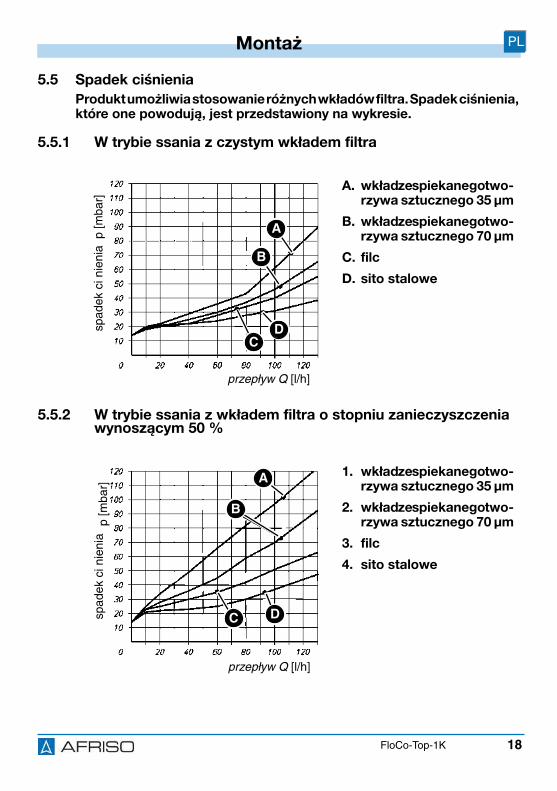
18
Montaż PL
FloCo-Top-1K
5.5 Spadek ciśnienia
Produkt umożliwia stosowanie różnych wkładów filtra. Spadek ciśnienia, które one powodują, jest przedstawiony na wykresie.
5.5.1 W trybie ssania z czystym wkładem filtra
5.5.2 W trybie ssania z wkładem filtra o stopniu zanieczyszczenia wynoszącym 50 %
A. wkład ze spiekanego two-rzywa sztucznego 35 μm
B. wkład ze spiekanego two-rzywa sztucznego 70 μm
C. filc
D. sito stalowe
1. wkład ze spiekanego two-rzywa sztucznego 35 μm
2. wkład ze spiekanego two-rzywa sztucznego 70 μm
3. filc
4. sito stalowe
przepływ Q [l/h]
spad
ekci
nien
iap
[mba
r]
A
B
DC
przepływ Q [l/h]
spad
ekci
nien
iap
[mba
r]
A
B
DC

19
Montaż PL
FloCo-Top-1K
5.6 Podłączanie węża odpowietrzającego
A. przyłącze węża z pierścieniem uszczelniającym o przekroju okrągłym
B. wąż odpowietrzający
1. Usunąć kołpak ochronny śru-bokrętem.
BA
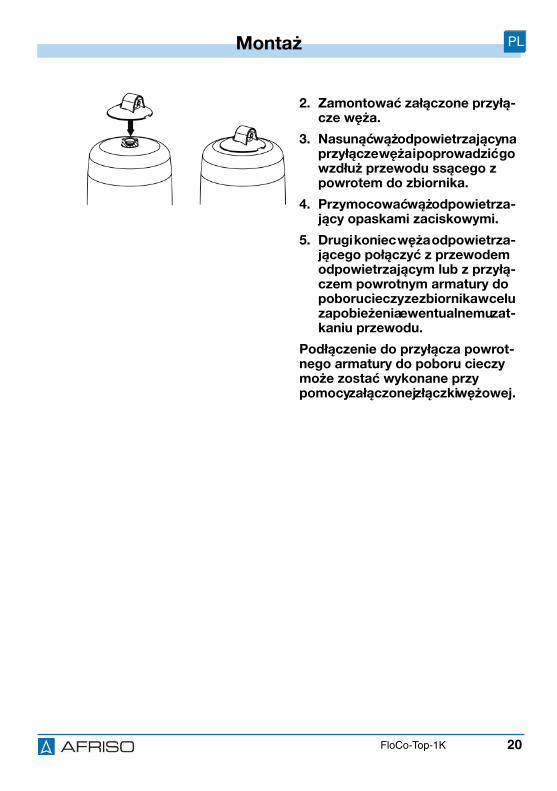
20
Montaż PL
FloCo-Top-1K
2. Zamontować załączone przyłą-cze węża.
3. Nasunąć wąż odpowietrzający na przyłącze węża i poprowadzić go wzdłuż przewodu ssącego z powrotem do zbiornika.
4. Przymocować wąż odpowietrza-jący opaskami zaciskowymi.
5. Drugi koniec węża odpowietrza-jącego połączyć z przewodem odpowietrzającym lub z przyłą-czem powrotnym armatury do poboru cieczy ze zbiornika w celu zapobieżenia ewentualnemu zat-kaniu przewodu.
Podłączenie do przyłącza powrot-nego armatury do poboru cieczy może zostać wykonane przy pomocy załączonej złączki wężowej.
21
Eksploatacja PL
FloCo-Top-1K
6 Eksploatacja
6.1 Poziom oleju w obudowie pływaka
Poziom cieczy zależy od warunków eksploatacyjnych instalacji i wynosi około 20 - 50 mm w trybie ssania. Przy wyższym poziomie oleju może dość do całkowitego napełnienia olejem obudowy pływaka pod warunkiem, że przewód ssący jest szczelnie ułożony. To zjawisko jest spowodowane pochłanianiem powietrza przez olej. Wraz z upływem czasu efekt ten prowa-dzi do zmniejszenia poduszki powietrznej. Jeśli zmieniają się warunki eks-ploatacyjne, na przykład przez obniżenie poziomu cieczy w zbiorniku, w obudowie pływaka tworzy się ponownie poduszka powietrzna.
6.2 Tryb ciśnieniowy
Ze względu na fakt, że w instalacji z pompą tłoczącą pracującą w trybie ciśnieniowym nie występuje zapowietrzanie związane z trybem pracy ssą-cej, nie jest celowe stosowanie w takim systemie niniejszego produktu. W trybie ciśnieniowym należy stosować filtr jednodrogowy z doprowadzeniem strumienia powrotnego. Jeśli instalacja wymaga wykorzystania odpowietrz-nika oleju opałowego, można zastosować układ „Flow-Control 3/K HT“ z umieszczonym na wej-ściu układu filtrem z mosiężnym naczyniem filtra lub wymiennym wkładem filtracyjnym.
Należy upewnić się, że przy tego typu zastosowaniu zostały podjęte sto-sowne działania, aby nie przekroczyć maksymalnie dopuszczalnego ciśnienia wejściowegoo poziomie 0,7 bar nawet w przypadku awarii (uszkodzonego reduktora ciśnienia) (korzystając na przykład z zaworu przelewowego, wyłącznika ciśnieniowego).
Należy upewnić się, że pod wężami palnika i pod odpowietrznikiem oleju umieszczona została wanna wychwytująca, przez którą nastąpi detekcja ewentualnego wycieku oleju oraz wyłączenie palnika.
22
Eksploatacja PL
FloCo-Top-1K
6.3 Gromadzenie się powietrza w naczyniu filtra
W zależności od rodzaju zastosowanego wkładu filtra oraz ciśnienia ssania zależnego od instalacji wkład filtra jest w stanie zatrzymać w mniejszym lub większym stopniu powietrze wydzielone z oleju.
Przed sitem filtracyjnym może utworzyć się poduszka powietrzna, która jest widoczna w naczyniu filtra. Wielkość poduszki powietrznej stanowi funkcję natężenia przepływu i ciśnienia ssania w filtrze, co oznacza, że przy dużej przepustowości przez sito może być porywana większailość cząsteczek powietrza niż przy małymnatężeniu przepływu (niskie zużycie oleju w pal-niku). W okresach pracy palnika, podczas których generowane jest podci-śnienie, stan ten powoduje spadek poziomu oleju w naczyniu filtra poza sitem filtracyjnym. Wnętrze sita filtracyjnego wypełnione jest przy tym całko-wicie przefiltrowanym olejem, wobec czego nie może dość do zakłóceń w eksploatacji. Nieregularna, przestrzenna struktura porów należącego do standardowego wyposażenia wkładu filtra ze spiekanego tworzywa sztucz-nego zapewnia bardzo dobrą przepuszczalność powietrza.
6.4 Stosowanie na terenach zagrożonych powodzią
Produkt nadaje się do stosowania na terenach zagrożonych powodzią i jest wodoszczelny oraz odporny na działanie wody pod ciśnieniem do 10 m słupa wody (1 bar ciśnienia zewnętrznego).
WSKAZÓWKA
NIESPRAWNY PRODUKT
• Należy upewnić się, że produkt został wymieniony po powodzi.
Nieprzestrzeganie niniejszych zaleceń może doprowadzić do powstania szkód materialnych.
23
Konserwacja PL
FloCo-Top-1K
7 Konserwacja
7.1 Okresy międzykonserwacyjne
Termin Czynność
W razie potrzeby Oczyścić elementy z tworzywa sztucznego przy użyciu roztworu wody z mydłem.
Nie stosować środków pielęgnacyjnych zawiera-jących rozpuszczalniki.
Jeden raz w roku lub w razie potrzeby
Wymienić wkład filtra.
Co 5 lat Wymienić węże palnika.
Najpóźniej po 20 latach Wymienić produkt.
24
Usuwanie usterek PL
FloCo-Top-1K
8 Usuwanie usterekUsterki, których nie da się zlikwidować przy pomocy czynności opisanych w niniejszym rozdziale, może usuwać wyłącznie producent.
Problem Możliwa przyczyna Usunięcie usterki
Duża ilość piany olejo-wej w komorze pływa-kowej ze względu na nadmiar zasysanego powietrza w odpo-wietrzniku (przekrocze-nie możliwej wydajności odpowietrzania > 4 l/h).
Nieszczelność w prze-wodzie ssącym.
Wykonać próbę ciśnie-niową przewodu ssą-cego (próbę próżniową lub ciśnieniową).
Nieszczelne śrubunki w strefie ssania.
Uszczelnić śrubunki.
Pierwsze uruchomienie bez oddzielnej pompy ssącej.
Zastosować pompę ssącą.
Zbyt duży wymiar prze-wodu ssącego.
Przestrzegać prędkości przepływu w zakresie 0,2 - 0,5 m/s (DIN 4755-2).

25
Usuwanie usterek PL
FloCo-Top-1K
Nieregularne wyłącze-nia awaryjne palnika.
Gromadzenie się powietrza w przewodzie ssącym ze względu na zbyt dużą średnicę (Ø) przewodu ssącego. Podczas otwierania zaworu antylewaro-wego po okresie wstęp-nego napowietrzania palnika może nastąpić przebicie większego pęcherza, który może wtedy spowodować wyłączenie awaryjne.
Prawidłowo zaprojekto-wać przewód ssący (patrz rozdział "Wyzna-czanie długości prze-wodu ssącego").
Problem Możliwa przyczyna Usunięcie usterki
26
Usuwanie usterek PL
FloCo-Top-1K
Brak możliwości zassa-nia oleju lub ciągłe zała-mywanie się słupa oleju.
Drobne nieszczelności na śrubunkach pomię-dzy armaturą do poboru cieczy na zbiorniku i palniku powodują przedostawanie się powietrza do przewodu ssącego. Dzieje się tak również podczas okre-sów postoju aż do odpowiedniej redukcji podciśnienia. W ten sposób w przewodzie ssącym tworzy się poduszka powietrzna.
Uszczelnić hermetycz-nie cylindryczne śru-bunki rurowe w obudo-wie przy pomocy miedzianych uszczelek płaskich.
W razie stosowania rury miedzianej miękkiej / średniotwardej użyć dodatkowo tulei wzmacniającej.
Skontrolować wszyst-kie powierzchnie uszczelniające pod kątem uszkodzeń.
Zamknąć zawór odcina-jący na armaturze do poboru cieczy i prze-prowadzić próbę ciśnie-niową (co najmniej -0,6 bar) na przyłączu zasila-jącym odpowietrznika oleju.
Pompa palnika nie generuje dostatecz-nego podciśnienia.
Przeprowadzić próbę ciśnienia ssania pompy. Pompa musi genero-wać podciśnienia na poziomie co najmniej -0,4 bar.
Pozostałe zakłócenia - Proszę skontaktować się z infolinią serwisową AFRISO.
Problem Możliwa przyczyna Usunięcie usterki
27
Wyłączenie z eksploatacji i utylizacja PL
FloCo-Top-1K
9 Wyłączenie z eksploatacji i utylizacjaProdukt należy utylizować zgodnie z obowiązującymi warunkami, normami oraz przepisami bezpieczeństwa.
10 ZwrotPrzed zwrotną wysyłką produktu wymagany jest kontakt z producentem.
11 GwarancjaInformacje dotyczące gwarancji są dostępne w naszych Ogólnych Warun-kach Handlowych w internecie pod adresem www.afriso.com lub w umowie kupna.
1. Wykonać demontaż produktu (patrz rozdział "Montaż" w odwrotnej kolejności).
2. Produkt poddać utylizacji.
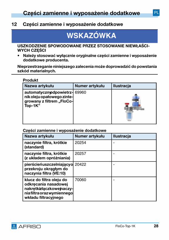
28
Części zamienne i wyposażenie dodatkowe PL
FloCo-Top-1K
12 Części zamienne i wyposażenie dodatkowe
Produkt
Części zamienne i wyposażenie dodatkowe
WSKAZÓWKAUSZKODZENIE SPOWODOWANE PRZEZ STOSOWANIE NIEWŁAŚCI-WYCH CZĘŚCI
• Należy stosować wyłącznie oryginalne części zamienne i wyposażenie dodatkowe producenta.
Nieprzestrzeganie niniejszego zalecenia może doprowadzić do powstania szkód materialnych.
Nazwa artykułu Numer artykułu Ilustracja
automatyczny odpowietrz-nik oleju opałowego zinte-growany z filtrem „FloCo-Top-1K”
69960 -
Nazwa artykułu Numer artykułu Ilustracja
naczynie filtra, krótkie (standard)
20254 -
naczynie filtra, krótkie(z układem opróżniania)
20257 -
pierścień uszczelniający o przekroju okrągłym do naczynia filtra (VE:10)
20422 -
klucz do filtra oleju do odkręcania nasadowej nakrętki złączkowej naczy-nia filtra oraz wymiennego wkładu filtracyjnego
70060 -
29
Części zamienne i wyposażenie dodatkowe PL
FloCo-Top-1K
rubunek rurowy wedługnormy DIN 3852 z mie-dzian uszczelk płask :
rura, Ø 6 mmrura, Ø 8 mmrura, Ø 10 mmrura, Ø 12 mm
20509205082051020512
-
tłokowy zawór antylewa-rowy „KAV“
20240 -
membranowy zawór antyle-warowy „MAV“
20139 -
w odpowietrzaj cy,polichlorek winylu PVC, Ø 4x 1 mm, rolka 20 m
20696 -
Nazwa artykułu Numer artykułu Ilustracja