
BETRIEBSANLEITUNG - keb-privod.rukeb-privod.ru/images/stories/upl/prod/arhiv/R4/Instrukciya...
132
06/2001 00.R4.F1A-K100 KEB COMBIVERT R4-F Version 1.0 BETRIEBSANLEITUNG INSTRUCTION MANUAL ANTRIEBSTECHNIK
Transcript of BETRIEBSANLEITUNG - keb-privod.rukeb-privod.ru/images/stories/upl/prod/arhiv/R4/Instrukciya...

06/2001
00.R
4.F
1A-K
100
KEB COMBIVERT R4-F Version 1.0
BETRIEBSANLEITUNGINSTRUCTION MANUAL
ANTRIEBSTECHNIK

D - 2
Alle Arbeiten zum Transport, Anschluß, zur Inbetrieb-nahme und Instandhaltung sind von qualifizierten, ver-antwortlichen Fachpersonal auszuführen. Unsachge-mäßes Verhalten kann schwere Personen- und Sach-schäden verursachen. Ein sicherer und störungsfreierBetrieb ist nur bei Einhaltung der jeweils gültigen Vor-schriften gemäß DIN VDE 0100, DIN VDE 0113, DINVDE 0160, DIN VDE 0875 sowie einschlägiger örtli-cher Bestimmungen gegeben.
Wird verwendet, wenn Lebenoder Gesundheit des Benut-zers gefährdet sind oder er-heblicher Sachschaden auf-treten kann.
Unbedingt beachten! Beson-dere Hinweise für den siche-ren und störungsfreien Be-trieb.
Hilfestellung, Tip
Nur qualifiziertesElektro-
Fachpersonal
Bevor Sie mit der Installation des KEB COMBIVERTR4-F beginnen, lesen Sie diese Anleitung bitte sorg-fältig und beachten Sie unbedingt die darin enthalte-nen Hinweise und Vorschläge.Diese Betriebsanleitung muß jedem Anwender zugäng-lich gemacht werden. Vor jeglichen Arbeiten muß sichder Anwender mit dem Gerät vertraut machen. Darunterfällt insbesondere die Kenntnis und Beachtung der Si-cherheits- und Warnhinweise. Lesen Sie deshalb unbe-dingt die „Technische Dokumentation Teil 1“. Sicherheits-relevante Texte sind kursiv ausgezeichnet.Die im Kapitel „Sicherheitshinweise“ aufgeführten Hin-weise sollten aus folgenden Gründen unbedingt be-achtet werden:• Sicherheit für Mensch und Maschine• Funktion und Störanfälligkeit• TÜV-Abnahmen und Zertifizierung• Garantie und Gewährleistung
Vorbemerkung
DangerWarningCaution
Attention,absolutelyobserve
TipInstructionInformation
All work referring to transport, connection,commissioning and maintenance are to be executedby qualified, responsible technical personnel.Inappropriate behaviour can cause severe bodilyinjuries or damage to property. A safe and troublefreeoperation is given only in compliance with the respectivevalid regulations according to DIN VDE 0100, DINVDE 0113, DIN VDE 0160, DIN VDE 0875 as well asthe relevant local regulations.
Is used, if life or health ofthe user are endangered orsubstantial damage toproperty can occur.
Absolutely observe! Spe-cial instructions for a safeand troublefree operation.
Help, Tip
Only qualifiedelectro-technical
personnel
Before starting with the installation of the KEBCOMBIVERT R4-F, read this instruction manualcarefully and absolutely observe the instructions andsuggestions contained in it.This instruction manual must be made available toevery user. Before carrying out any work the usermust familiarize himself with the unit. This applies inparticular to the knowledge and observation of thesafety and warning instructions. For that reason it isabsolutely necessary to read the „TechnicalDocumentation Part 1“ first.Safety-relevants texts are written in italics.The notes specified in the chapter „Safety Instructions“should be strictly observed for the following reasons:• Safety for man and machine• Function and susceptibility to faults• TÜV-acceptance and certification• Warranty
Preliminary Remark
GefahrWarnungVorsicht
Achtung,unbedingtbeachten
TipHinweisInformation
D GBSeiten D-3 . . . D-66 Pages GB-3 . . . GB-66

ANTRIEBSTECHNIK
D - 3
Inhaltsverzeichnis
Inhaltsverzeichnis
1. Sicherheitshinweise .............................................5
2. Produktbeschreibung...........................................92.1 Verwendungszweck ............................................................ 9
2.2 Einsatzbedingungen ......................................................... 10
2.3 Geräteidentifikation ........................................................... 10
3. Transport und Lagerung ....................................11
4. Installation ............................................................124.1 Montage des Gerätes ........................................................ 12
4.1.1 Abmessungen ..................................................................... 12
4.1.2 Umweltbedingungen ........................................................... 13
4.1.3 Einbauhinweise................................................................... 13
4.1.4 Hinweise zur EMV-gerechten Verdrahtung .......................... 14
4.2 Anschluß Leistungsteil ..................................................... 16
4.2.1 Temperaturüberwachung Kommutierungsdrossel ............... 16
4.2.2 Standardanschluß ............................................................... 16
4.3 Technische Daten .............................................................. 17
4.4 OL - Funktion - Überlastbereich ....................................... 18
5. Steuerklemmleiste X2 .........................................195.1 Anschluß der Steuerklemmen .......................................... 20
6. Bedienung des Gerätes......................................216.1 Initialisierung...................................................................... 21
6.2 Bedienung während des Betriebes ................................. 21
6.2.1 Bedienung mittels Interface-Operator .................................. 22
6.2.2 Bedienung mittels PC und Systemsoftware KEB COMBIVIS . 236.3 Tastaturbedienung ............................................................ 236.3.1 Standardbedienung ............................................................. 236.3.2 Mode 1, Anzeige der Parameteridentifikation ...................... 236.3.3 Mode 2, Ändern von Parameterwerten ................................ 246.4 Sonderanzeigen ................................................................ 25

D - 4
Inhaltsverzeichnis
Inhaltsverzeichnis7. Parameterstruktur................................................267.1 Funktionen der Parametergruppen ................................. 277.2 Passwortstruktur ............................................................... 287.3 Bedienebene 2: Customer-Mode ...................................... 297.4 Wiederherstellen der Werkseinstellung ........................... 30
8. Funktionsbeschreibung .....................................318.1 Run (ru)-Parameter ............................................................ 318.2 Protection (Pn)-Parameter ................................................ 378.3 Control (cs)-Parameter ...................................................... 388.3.1 Abgleich des Zwischenkreisspannungsreglers ................... 418.3.2 Einstellhilfe Zwischenkreisspannungsregler ....................... 428.3.3 Dynamik verbessern ............................................................ 438.3.4 Stromverlauf optimieren....................................................... 438.4 Drive (ds)-Parameter ......................................................... 438.5 Free-programmable (Fr)-Parameter ................................. 438.6 User Definition (ud)-Parameter ......................................... 448.7 Analog I/O (An)-Parameter ................................................ 468.8 Digital Input (di)-Parameter ............................................... 478.9 Digital Output (do)-Parameter ........................................... 518.10 Level (LE)-Parameter ......................................................... 548.11 Information (In)-Parameter ................................................ 55
9. Parameterübersicht .............................................579.1 Tabelle ru-Parameter ......................................................... 579.2 Tabelle pn-Parameter ........................................................ 589.3 Tabelle cs-Parameter ......................................................... 589.4 Tabelle ud-Parameter ........................................................ 599.5 Tabelle Fr-Parameter ......................................................... 609.6 Tabelle An-Parameter ........................................................ 609.7 Tabelle di-Parameter .......................................................... 609.8 Tabelle do-Parameter ........................................................ 619.9 Tabelle LE-Parameter ........................................................ 629.10 Tabelle In-Parameter .......................................................... 639.11 Tabelle Supervisor-Parameter .......................................... 63
10. Wartung ................................................................64
11. Außerbetriebnahme, Abbau und Entsorgung .64
12. Fehlerdiagnose....................................................65

ANTRIEBSTECHNIK
D - 5
Sicherheitshinweise
Lebensgefahr
Nur durchFachpersonal
Allgemeine HinweiseKEB COMBIVERT R4-F werden mit Spannungen betrieben, die bei Be-rührung einen lebensgefährlichen Schlag hervorrufen können. Währenddes Betriebes können sie ihrer Schutzart entsprechend spannungs-führende, blanke, sowie heiße Oberflächen besitzen.
Wenn an einem KEB COMBIVERT R4-F angeschlossene Umrichtergeneratorisch betrieben werden und die Abschaltzeit des KEBCOMBIVERT R4-F (Parameter Pn. 59) bei Netzausfall > 0 s eingestelltist, wird auch bei Netzausfall Energie in das Versorgungsnetz zurück-gespeist. Deshalb kann nach Abschalten des Versorgungsnetzes einelebensgefährlich hohe Spannung in der Anlage bestehen.
Vor dem Arbeiten an der Anlage ist unbedingt die Spannungsfreiheitdurch Messungen in der Anlage zu kontrollieren!
Bei unzulässigem Entfernen von erforderlichen Abdeckungen, bei un-sachgemäßem Einsatz, bei falscher Installation oder Bedienung, bestehtdie Gefahr von schweren Personen- oder Sachschäden.
Alle Arbeiten zum Transport, zur Installation und Inbetriebnahme sowieInstandhaltung sind nur von qualifiziertem Fachpersonal auszuführen(IEC 364 bzw. CENELEC HD 384 (VDE 0100) und nationale Unfallver-hütungsvorschriften beachten).
Qualifiziertes Fachpersonal im Sinne dieser Anleitung bezeichnet Per-sonen, welche aufgrund ihrer fachlichen Ausbildung und Erfahrung,Kenntnisse der einschlägigen Normen sowie Unterweisung in das spe-zielle Umfeld der Antriebstechnik eingewiesen sind und die dadurch dieihnen übertragenen Aufgaben beurteilen und mögliche Gefahren erken-nen können (EN 50178 (VDE 0100, VDE 0160), EN 60204 (VDE 0113)sowie die gültigen örtlichen Bestimmungen einhalten).
Bestimmungsgemäßer GebrauchKEB COMBIVERT R4-F dienen der Rückspeisung von Energie aus demDC-Zwischenkreis von Frequenzumrichtern. Der Betrieb der KEBCOMBIVERT R4-F ist nur in Verbindung mit Frequenzumrichtern zuläs-sig. Der Anschluß anderer elektrischer Verbraucher an die R4-F-Ein-und Rückspeiseeinheiten ist unzulässig und kann zur Zerstörung derGeräte führen.
Die Inbetriebnahme (d. h. die Aufnahme der bestimmungsmäßigen Ver-wendung) des KEB COMBIVERT R4-F ist solange untersagt, bis fest-gestellt wurde, daß die Anlage oder Maschine den Bestimmungen derEG-Richtlinie 89/392/EWG (Maschinenrichtlinie) sowie der EMV-Richt-linie (89/336/EWG) und deren Änderungen entspricht.
1. Sicherheitshin-weise
Normenbeachten

D - 6
Kondensator-entladezeitbeachten
Spannungengegen Erde
Nur festerAnschluß
Die KEB COMBIVERT R4-F erfü l len die Anforderungen derNiederspannungsrichtlinie 73/231/EWG. Die harmonisierten Normen derReihe EN 50178 (VDE 0160) in Verbindung mit EN 60439-1 (VDE 0660Teil 500) und EN 60146 (VDE 0558) werden angewendet.
Transport und LagerungDie KEB COMBIVERT R4-F sind vor unzulässiger Beanspruchung zuschützen. Insbesondere dürfen bei Transport und Handhabung keine Bau-elemente verbogen und/oder Isolationsabstände verändert werden.
Die Geräte enthalten elektrostatisch gefährdete Bauelemente, die durchunsachgemäße Behandlung zerstört werden können. Die Berührungelektronischer Bauelemente und Kontakte ist daher zu vermeiden. Beimechanischen Defekten an elektrischen und elektronischen Komponen-ten, darf das Gerät nicht in Betrieb genommen werden, da eine Einhal-tung angewandter Normen nicht mehr gewährleistet ist.
InstallationBeim Einbau ist unbedingt auf ausreichende Mindestabstände, sowieausreichende Kühlung zu achten. Klimatische Bedingungen sind ent-sprechend EN 50178 (VDE 0160) einzuhalten.
Elektrischer AnschlußVor jeglichen Installations- und Anschlußarbeiten ist die Anlage span-nungslos zu schalten und entsprechend zu sichern.
Nach dem Freischalten des KEB COMBIVERT R4-F sind die Zwischen-kreiskondensatoren noch kurzzeitig mit hoher Spannung geladen. Ar-beiten am Gerät dürfen daher erst 5 Minuten nach dem Abschalten aus-geführt werden.
Der Anschluß des KEB COMBIVERT R4-F ist nur an symmetrische Netzemit einer Leiterspannung Phase (L1, L2, L3) gegen N/PE von max. 290V zulässig.
Die KEB COMBIVERT R4-F sind nur für einen festen Anschluß be-stimmt, da inbesondere beim Einsatz von Filtern Ableitströme > 3,5 mAauftreten. Ein Schutzleiterquerschnitt von mindestens 10 mm2 Kupferoder die Verlegung eines zweiten Leiters elektrisch parallel zum Schutz-leiter über getrennte Klemmen ist vorgeschrieben. Generell mit kürze-ster Verbindung zur Haupterde sternförmig erden (Erdschleifen vermei-den).
Sicherheitshinweise
Vor Berührungschützen

ANTRIEBSTECHNIK
D - 7
Sicherheitshinweise
Störungenvermeiden
Isolations-messungen
Potential-unterschiede
Bei einer Isolationsmessung nach EN 60204 (VDE 0113) muß wegenZerstörungsgefahr der Leistungshalbleiter das Gerät vollständig abge-klemmt werden. Dies ist nach Norm zulässig, da alle Geräte im Rahmender Endkontrolle bei KEB einer Hochspannungsprüfung, wie in EN50178 (VDE 0160) beschrieben unterzogen werden.
Bei Verwendung von Komponenten, die keine potentialgetrennten Ein-/Ausgänge verwenden, ist es erforderlich, daß zwischen den zu verbin-denden Komponenten Potentialgleichheit besteht (z. B. durch Ausgleichs-leitung). Bei Mißachtung können die Komponenten durch Aus-gleichströme zerstört werden.
Ein störungsfreier und sicherer Betrieb des KEB COMBIVERT R4-F istnur unter Beachtung der folgenden Anschlußhinweise zu erwarten. BeiAbweichungen von diesen Vorgaben können im Einzelfall Fehlfunktio-nen und Schäden auftreten.• Netzspannung beachten!• Leistungs- und Steuerkabel getrennt verlegen (> 15 cm)!• Abgeschirmte/verdrillte Steuerleitungen verwenden. Schirm einseitig
an den KEB COMBIVERT R4-F auf PE legen!• Zur Steuerung der Logikeingänge nur geeignete Schaltelemente ver-
wenden, deren Kontakte für Kleinspannungen geeignet sind!• Gehäuse des KEB COMBIVERT R4-F gut erden. Schirme von
Leistungsleitungen beidseitig großflächig auflegen (Lack entfernen)!• Den Schaltschrank oder die Anlage zur Haupterde hin
sternpunktförmig erden. (Erdschleifen unbedingt vermeiden!)
Wenn beim Errichten von Anlagen Personenschutz gefordert ist, müs-sen Ein- und Rückspeiseeinheiten gemäß EN 50178 (VDE 0160) wiefolgt abgesichert werden:
• 3phasige Geräte durch RCMA’s mit Trenner (bevorzugtzu verwenden) oder RCD’s Typ B (allstromsensitive FI’s).
Der Auslösestrom der RCD’s sollte 300 mA oder mehr betragen, umvorzeitiges Auslösen durch Ableitströme des Umrichters (ca. 200 mA)zu vermeiden.
Abhängig von der Belastung, der Motorleitungslänge und dem Einsatzeines Funkentstörfilters können erheblich größere Ableitströme auftre-ten.
Die Anschlußhinweise der jeweiligen Hersteller sowie die gültigen ört-lichen Bestimmungen, sind beim Anschluß zu beachten.
RCD(Fehlerstrom-
schutzschalter)

D - 8
In Abhängigkeit der vorhandenen Netzform (TN, IT, TT) sind weitereSchutzmaßnahmen gemäß VDE 0100 Teil 410 (Teil 4, Kap. 41) erforder-lich.
Bei TN-Netzen ist dies z. B. Schutz durch Überstromeinrichtung, bei IT-Netzen Isolationsüberwachung mit Pulscode-Meßverfahren. Bei allenNetzformen kann Schutztrennung verwendet werden, sofern die erfor-derliche Leistung und Leitungslänge dies zulassen.
BetriebshinweiseVor der Inbetriebnahme sind alle zugehörigen Abdeckungen wieder an-zubringen sowie Klemmen und Verschraubungen auf festen Sitz zu über-prüfen.
Die KEB COMBIVERT R4-F können typenabhängig so eingestellt seinoder werden, daß sie nach einem Fehlerfall (z. B. Unterspannungsfehler)selbsttätig wieder anlaufen. Anlagen müssen deshalb ggf. mit zusätzli-chen Überwachungs- und Schutzvorrichtungen (gem. Gesetz über tech-nische Arbeitsmittel, Unfallverhütungsvorschriften usw.) ausgerüstetwerden.
Die KEB COMBIVERT R4-F sind bedingt kurzschlußfest (EN 50178(VDE 0160)). Nach dem Zurücksetzen der internen Schutzeinrichtungenist die bestimmungsgemäße Funktion gewährleistet. Ausnahmen:
• Treten am Ausgang wiederholt Erd- oder Kurzschlüsse auf, kann dieszu einem Defekt am Gerät führen.
• Tritt ein Kurzschluß während des generatorischen Betriebes auf, kanndies zu einem Defekt am Gerät führen.
Die erhöhte Zwischenkreisspannung von ca. 680 V (statt 540V bei 400VNetzen) kann bei nachgeschalteten Motoren zu einer vorzeitigen Alte-rung des Isolationssystems führen. Als Empfehlung sollten nur Motorenmit entsprechend hoher Spannungsfestigkeit eingesetzt werden.
AutomatischerWiederanlauf
Bedingtkurzschlußfest
Sicherheitshinweise
Motorisolations-festigkeit
ANTRIEBSTECHNIK
D - 9
Produktbeschreibung
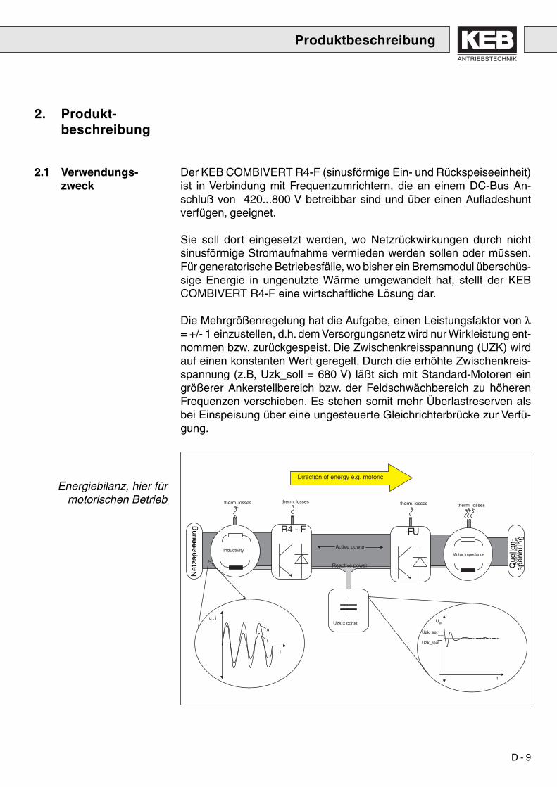
2. Produkt-beschreibung
Der KEB COMBIVERT R4-F (sinusförmige Ein- und Rückspeiseeinheit)ist in Verbindung mit Frequenzumrichtern, die an einem DC-Bus An-schluß von 420...800 V betreibbar sind und über einen Aufladeshuntverfügen, geeignet.
Sie soll dort eingesetzt werden, wo Netzrückwirkungen durch nichtsinusförmige Stromaufnahme vermieden werden sollen oder müssen.Für generatorische Betriebesfälle, wo bisher ein Bremsmodul überschüs-sige Energie in ungenutzte Wärme umgewandelt hat, stellt der KEBCOMBIVERT R4-F eine wirtschaftliche Lösung dar.
Die Mehrgrößenregelung hat die Aufgabe, einen Leistungsfaktor von λ= +/- 1 einzustellen, d.h. dem Versorgungsnetz wird nur Wirkleistung ent-nommen bzw. zurückgespeist. Die Zwischenkreisspannung (UZK) wirdauf einen konstanten Wert geregelt. Durch die erhöhte Zwischenkreis-spannung (z.B, Uzk_soll = 680 V) läßt sich mit Standard-Motoren eingrößerer Ankerstellbereich bzw. der Feldschwächbereich zu höherenFrequenzen verschieben. Es stehen somit mehr Überlastreserven alsbei Einspeisung über eine ungesteuerte Gleichrichterbrücke zur Verfü-gung.
2.1 Verwendungs-zweck
Energiebilanz, hier fürmotorischen Betrieb
R4 - F FU
Reactive power
Active powerInductivity
Motor impedance
therm. losses therm. losses therm. losses therm. losses
Uzk = const.u , i
t
t
Uzk
Uzk_set
Uzk_real
u
i
Direction of energy e.g. motoric
Sou
rce
volta
ge
Mai
ns v
olta
ge
Que
llen-
spa
nn
un
g
Ne
tzsp
an
nu
ng

D - 10
R4-F FU
NETZ MOTOR
u_oe
Der KEB COMBIVERT R4-F kann überall dort eingesetzt werden, wofolgende Betriebsbedingungen gegeben sind:· 3-Phasen 300 - 440 V / 45-65Hz Netze
(Phasenspannungsunsymmetrie +/- 15%).· Frequenzumrichter mit DC-Bus Anschluß.· max.Umgebungstemperatur = 45°C.Aufgrund des gesteuerten Pulsgleichrichters am Eingang des KEBCOMBIVERT R4-F, kommt es zu erheblichen Potentialunterschiedenzwischen dem Zwischenkreispotential und dem Erdpotential .
Aus diesem Grund, darf keine kapazitive oder induktive Verbindungvom Zwischenkreis zum Erdpotential bestehen. Allerdings werdenEntstörkondensatoren in einigen bestehenden Frequenzumrichterneingesetzt. Die Verbindung zum Erdpotential ist mit Rücksprachedes Herstellers zu entfernen.
2.2 Einsatz-bedingungen
Produktbeschreibung
2.3 Geräteidentifikation
XX.R4.XXX-XXXX
Steckplatz-Option
Typ Steuerkarte
nicht definiertGehäusegröße
Anschluß
SpannungTaktfrequenz
Gerätetyp
Gerätegröße
0 Standard ohne Steckplatzbelegung1-9 / mit belegtem Steckplatz OperatorA-Z und/oder bel. Steckplatz Zusatzkarte0 netzsynchron getaktet / 8 - 16 kHz2 / 4 200 V- / 400 V-Klasse3 3-phasig4, A Hinweis auf Sonder-/Kundenversion,
400 V-KlasseGehäusegröße
0 - - -S / F Standard (blockförmige Rückspeisung) (S)
sinusförmige Ein-/Rückspeisung (F)R4 Rückspeiseeinheit
ANTRIEBSTECHNIK
D - 11
Lebensgefahr
Nur durchFachpersonal
Normenbeachten
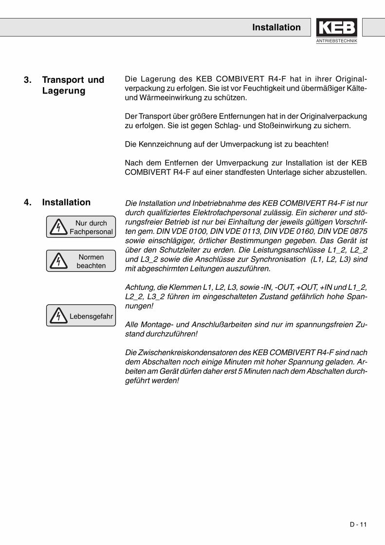
Die Lagerung des KEB COMBIVERT R4-F hat in ihrer Original-verpackung zu erfolgen. Sie ist vor Feuchtigkeit und übermäßiger Kälte-und Wärmeeinwirkung zu schützen.
Der Transport über größere Entfernungen hat in der Originalverpackungzu erfolgen. Sie ist gegen Schlag- und Stoßeinwirkung zu sichern.
Die Kennzeichnung auf der Umverpackung ist zu beachten!
Nach dem Entfernen der Umverpackung zur Installation ist der KEBCOMBIVERT R4-F auf einer standfesten Unterlage sicher abzustellen.
Die Installation und Inbetriebnahme des KEB COMBIVERT R4-F ist nurdurch qualifiziertes Elektrofachpersonal zulässig. Ein sicherer und stö-rungsfreier Betrieb ist nur bei Einhaltung der jeweils gültigen Vorschrif-ten gem. DIN VDE 0100, DIN VDE 0113, DIN VDE 0160, DIN VDE 0875sowie einschlägiger, örtlicher Bestimmungen gegeben. Das Gerät istüber den Schutzleiter zu erden. Die Leistungsanschlüsse L1_2, L2_2und L3_2 sowie die Anschlüsse zur Synchronisation (L1, L2, L3) sindmit abgeschirmten Leitungen auszuführen.
Achtung, die Klemmen L1, L2, L3, sowie -IN, -OUT, +OUT, +IN und L1_2,L2_2, L3_2 führen im eingeschalteten Zustand gefährlich hohe Span-nungen!
Alle Montage- und Anschlußarbeiten sind nur im spannungsfreien Zu-stand durchzuführen!
Die Zwischenkreiskondensatoren des KEB COMBIVERT R4-F sind nachdem Abschalten noch einige Minuten mit hoher Spannung geladen. Ar-beiten am Gerät dürfen daher erst 5 Minuten nach dem Abschalten durch-geführt werden!
3. Transport undLagerung
4. Installation
Installation
D - 12
4. Installation
Installation
4.1 Montage des Gerätes
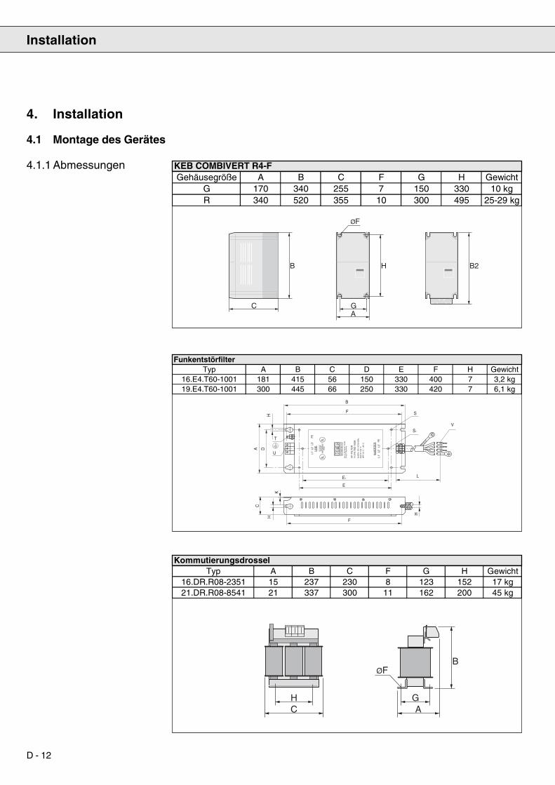
4.1.1 Abmessungen
C
B B2H
ØF
GA
ØFB
H GC A
KEB COMBIVERT R4-FGehäusegröße A B C F G H Gewicht
G 170 340 255 7 150 330 10 kgR 340 520 355 10 300 495 25-29 kg
T
AN
TR
IEB
ST
EC
HN
IK
HF
-FIL
TE
R14.F
4.T
60-1
008
LIN
E
INV
ER
TE
R
Kar
l E. B
rinkm
ann
Gm
bHD
-326
77 B
arnt
rup
3x50
0V+1
0% A
C/5
0-60
Hz
20A
@ T
-45
°CH
PF:
-25
°C -
+85
°C
E 1
6754
4LI
ST
ED
IND
CO
NT
EO
5D12
LLLUUU
LLLUUU
L1'
L2'
L3'
PE
L1'
L2'
L3'
PE
U
DA
H
B
F S
S1
V
LE1
E
H
H
C
K
F
FunkentstörfilterTyp A B C D E F H Gewicht
16.E4.T60-1001 181 415 56 150 330 400 7 3,2 kg19.E4.T60-1001 300 445 66 250 330 420 7 6,1 kg
KommutierungsdrosselTyp A B C F G H Gewicht
16.DR.R08-2351 15 237 230 8 123 152 17 kg21.DR.R08-8541 21 337 300 11 162 200 45 kg
ANTRIEBSTECHNIK
D - 13
4.1.2 Umweltbedingungen
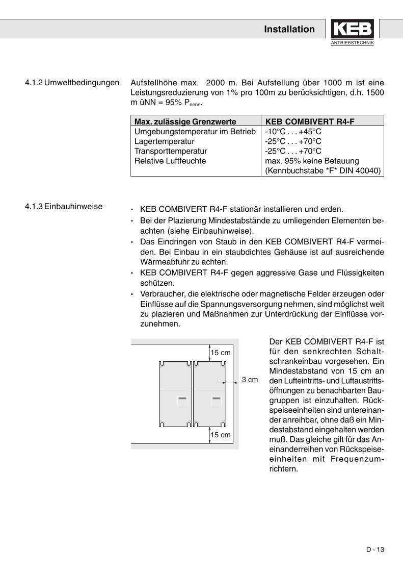
4.1.3 Einbauhinweise · KEB COMBIVERT R4-F stationär installieren und erden.· Bei der Plazierung Mindestabstände zu umliegenden Elementen be-
achten (siehe Einbauhinweise).· Das Eindringen von Staub in den KEB COMBIVERT R4-F vermei-
den. Bei Einbau in ein staubdichtes Gehäuse ist auf ausreichendeWärmeabfuhr zu achten.
· KEB COMBIVERT R4-F gegen aggressive Gase und Flüssigkeitenschützen.
· Verbraucher, die elektrische oder magnetische Felder erzeugen oderEinflüsse auf die Spannungsversorgung nehmen, sind möglichst weitzu plazieren und Maßnahmen zur Unterdrückung der Einflüsse vor-zunehmen.
Der KEB COMBIVERT R4-F istfür den senkrechten Schalt-schrankeinbau vorgesehen. EinMindestabstand von 15 cm anden Lufteintritts- und Luftaustritts-öffnungen zu benachbarten Bau-gruppen ist einzuhalten. Rück-speiseeinheiten sind untereinan-der anreihbar, ohne daß ein Min-destabstand eingehalten werdenmuß. Das gleiche gilt für das An-einanderreihen von Rückspeise-einheiten mit Frequenzum-richtern.
Aufstellhöhe max. 2000 m. Bei Aufstellung über 1000 m ist eineLeistungsreduzierung von 1% pro 100m zu berücksichtigen, d.h. 1500m üNN = 95% Pnenn.
Max. zulässige Grenzwerte KEB COMBIVERT R4-FUmgebungstemperatur im Betrieb -10°C . . . +45°CLagertemperatur -25°C . . . +70°CTransporttemperatur -25°C . . . +70°CRelative Luftfeuchte max. 95% keine Betauung
(Kennbuchstabe *F* DIN 40040)
15 cm
15 cm
3 cm
Installation

D - 14
4.1.4 Hinweise zur EMV-gerechtenVerdrahtung
Installation
• Schaltschrank oder Anlage funktions- und sachgerecht aufbauen
• Um Störungseinkopplung zu vermeiden, sind:
a) Netz-/Versorgungsleitungen,b) Motorleitungen von Frequenzumrichtern/Servostellern,c) Steuer und Datenleitungen (Niedervoltebene < 48 V), mit
einem Abstand von mindestens 15 cm zu verlegen.
• Um niederohmige HF-Verbindungen zu erhalten, müssen Erdungenund Schirmungen sowie sonstige metallische Verbindungen (z. B.Montageplatte, eingebaute Geräte) großflächig auf metallisch blan-ken Untergrund aufgelegt werden. Erdungs- und Potentialausgleichs-leitungen mit möglichst großem Querschnitt (mind. 10 mm²) oder di-cken Massebändern verwenden.
• Werden externe Funkentstörfilter eingesetzt, so sind diese mit max.30 cm Abstand zur Störquelle und mit sehr gutem, flächigem Kontaktzur Montagefläche einzubauen.
• Induktive Schaltglieder (Schütze, Relais usw.) immer mit Entstör-gliedern wie Varistoren, RC-Gliedern oder Schutzdioden versehen.
• Alle Verbindungen so kurz wie möglich halten und dicht am Bezugs-potential führen, denn frei schwebende Leitungen wirken wie Anten-nen.
• Vermeiden Sie Reserveschleifen an allen Anschlußkabeln. Nicht be-legte Litzen beidseitig am Schutzleiter auflegen.
• Bei ungeschirmten Leitungen müssen Hin- und Rückleiter verdrilltwerden, um symmetrische Störungen zu dämpfen.
Auf der nachfolgenden Seite finden Sie Beispiele zum Aufbauund zur Verdrahtung eines EMV-gerechten Schaltschrankes.

ANTRIEBSTECHNIK
D - 15
3
4
10
9
13
1
2
9a
13a
5 7
8
6
14
15 cm
15 cm
Installationsschema - EMV-gerechter Schaltschrankaufbau
1 Netzsicherung
2 Hauptschütz
3 Funkentstörfilter
4 Kommutierungsdrossel
5 R4-Ein- und Rückspeiseeinheit
6 Zwischenkreissicherung
7 Frequenzumrichter
8 Motorzuleitung
9 Montageplatte ist gemeinsamer Sternpunkt (PE)
9a Sternpunkt (PE) für Steuerbereich
10 Potentialausgleich mit der Gebäudeerde
13 Netzanschluß
13a Netzanschluß, Steuerbereich
14 Steuerleitungen, Gehäuse großflächig angebunden
Das obige Installationsschema stellt die optimale Lösung in derAnordnung der Geräte dar. Sofern es die Abmessungen des Schalt-schrankes zulassen, sollte diese Schema verwirklicht werden.
Steuerbereich Leistungsbereich
Installation

D - 16
4.2 AnschlußLeistungsteil
Klemme FunktionL1, L2, L3 SynchronisationOH, OH Anschluß für Temperatursensor
für Kommutierungsdrossel-IN, +IN Eingangsklemmen für +/- DC-Zwischenkreis-OUT, +OUT Ein-/Ausgangsklemmen für +/- DC-ZwischenkreisL1_2, L2_2, L3_2 3-phasiger Netzanschluß
Netzseitig und im DC-Zwischenkreis muß das Gerät mit Sicherungender Betriebsklasse gR abgesichert werden. Um unzulässig hoheKommutierungseinbrüche zu vermeiden, muß netzseitig eineKommutierungsdrossel vorgeschaltet werden. Der Anschluß derSynchronisationsleitungen wird über Vorsicherungen max. 4A (gem. VDELeitungsschutz), mit verdrillten Leitungen 0,75 mm2 ausgeführt.
4.2.1 Temperatur-überwachungKommutierungs-drossel
4.2.2 Standardanschluß Es können auch mehrere Frequenzumrichter an den DC-Bus ange-schlossen werden. Auf die Gesamtanschlussleistung ist zu achten.
L1 L2 L3OH OH
- IN - OUT + OUT + IN L1 _2 L2 _2 L3 _2
Brücke, wenn keineÜberwachung erfolgt
Thermokontakt(Öffner)
Temperaturfühler (PTC)Ansprechwiderstand > 4 kΩRückstellwiderstand < 750 Ω(gemäß VDE 0664)
Installation
R4-IN -OUT +OUT +IN
L1_2 L2_2 L3_2 PE
DC-FU+UZK -UZK U V W
PE
DC-FU+UZK -UZK U V W
PE
M3~
M3~
L1 L2 L3
PE
L1L2L3
Filter
3
L1L2L3
L1L2L3
L3'L3'L2'L2'L1'L1'
ANTRIEBSTECHNIK
D - 17
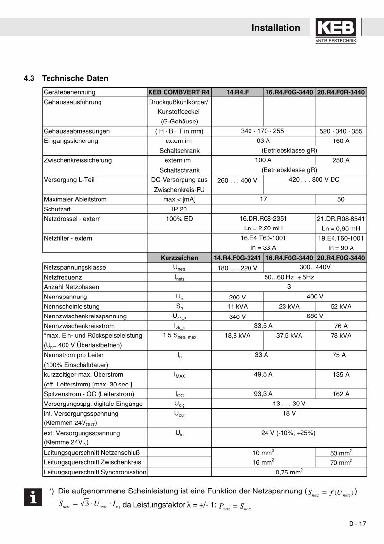
4.3 Technische Daten
*) Die aufgenommene Scheinleistung ist eine Funktion der Netzspannung (S f Unetz netz= ( ) )
S U Inetz netz n= ⋅ ⋅3 , da Leistungsfaktor λ = +/- 1: P Snetz netz=
Installation
Gerätebenennung KEB COMBVERT R4 14.R4.F 16.R4.F0G-3440 20.R4.F0R-3440
Gehäuseausführung Druckgußkühlkörper/
Kunstoffdeckel
(G-Gehäuse)
Gehäuseabmessungen ( H · B · T in mm) 520 · 340 · 355
Eingangssicherung extern im 160 A
Schaltschrank
Zwischenkreissicherung extern im 250 A
Schaltschrank
Versorgung L-Teil DC-Versorgung aus 260 . . . 400 VZwischenkreis-FU
Maximaler Ableitstrom max.< [mA] 50
Schutzart IP 20
Netzdrossel - extern 100% ED 21.DR.R08-8541
Ln = 0,85 mH
Netzfilter - extern 19.E4.T60-1001
In = 90 A
Kurzzeichen 14.R4.F0G-3241 16.R4.F0G-3440 20.R4.F0G-3440
Netzspannungsklasse Unetz 180 . . . 220 VNetzfrequenz fnetz
Anzahl Netzphasen
Nennspannung Un 200 VNennscheinleistung Sn 11 kVA 23 kVA 52 kVA
Nennzwischenkreisspannung Uzk_n 340 VNennzwischenkreisstrom Izk_n 76 A
*max. Ein- und Rückspeiseleistung 1.5 Snetz_max 18,8 kVA 37,5 kVA 78 kVA
(Un= 400 V Überlastbetrieb)
Nennstrom pro Leiter In 75 A
(100% Einschaltdauer)
kurzzeitiger max. Überstrom IMAX 135 A
(eff. Leiterstrom) [max. 30 sec.]
Spitzenstrom - OC (Leiterstrom) IOC 162 A
Versorgungsspg. digitale Eingänge Udig
int. Versorgungsspannung Uout
(Klemmen 24VOUT)
ext. Versorgungsspannung Uin
(Klemme 24VIN)
Leitungsquerschnitt Netzanschluß 50 mm2
Leitungsquerschnitt Zwischenkreis 70 mm2
Leitungsquerschnitt Synchronisation
680 V
33,5 A
33 A
49,5 A
Ln = 2,20 mH
16.E4.T60-1001
In = 33 A
300...440V
(Betriebsklasse gR)
420 . . . 800 V DC
17
16.DR.R08-2351
340 · 170 · 255
63 A
(Betriebsklasse gR)
100 A
50...60 Hz ± 5Hz
400 V
0,75 mm2
3
24 V (-10%, +25%)
13 . . . 30 V
18 V
93,3 A
10 mm2
16 mm2

D - 18
0
50
100
150
200
0 20 40 60 80 100
Auslastung [%]
Zei
t [s
]
4.4 OL - Funktion Über-lastbereich
0
50
100
150
200
250
300
350
100 120 140 160
Auslastung [%]
Zei
t [s
]
Auslösezeitraum:
Rückstellzeitraum:
Installation

ANTRIEBSTECHNIK
D - 19
5. Steuerklemm-leiste X2
1 2 3 4 5 6 7 8 9 10 11 12 13 14 15 16 17 18 19 20 21 22 23
Installation
Klemme Name Spezifikation BeschreibungX2.1 RLA1 Dauergrenzstrom= 6A;400V~/300V- RA1 / RC1 SchließerX2.2 RLB1 Schaltleistung ~ 1500 VA RB1 / RC1 ÖffnerX2.3 RLC1X2.4 freiX2.5 I1 Störspannungsfestigkeit : 2kV Programmierbarer Eingang
logisch 1: +/- (12..30V)Logik: NPN/PNP
intern. Eingangswiderstand: ca. 2kΩX2.6 Uout +18V(+/- 20%); max 20mA +18V Ausgang
Bei Anschluss einer ext. Spannungist Uout ~ Ext.Spg ( X2.18)
X2.7 EXTGND Masse für Uout u. dig. I/OX2.8 ST siehe Klemme X2.5 ReglerfreigabeX2.9 Uout siehe Klemme X2.6
X2.10 EXTGND siehe Klemme X2.7X2.11 RST siehe Klemme X2.5 ResetX2.12 Uout siehe Klemme X2.6X2.13 EXTGND siehe Klemme X2.7X2.14 OUT1 programmmierbarer PNP-Transistor- digitaler Ausgang
Ausgang, ca. 16V(+/- 20%) / max.20mA bei ext. Versorgung ca.
(Uout - 3V) +/-20%/ max. 20mAX2.15 ANOUT Spannungsbereich: +/- 10 V Analogausgang
Innenwiderstand : 100 ΩAuflösung : 12 Bit
X2.16 GND Masse für ANOUTX2.17 freiX2.18 24V IN Externe Versorgungsspannung (+24..30V) ext. Spannungsversorgung
für die E/A´s. Wenn ext. Komponenten ausUout mit Stromaufnahme > 110mA versorgtwerden sollen, muß eine ext. Versorgungan Klemme X2.18 zur Verfügung gestellt
werden. Bezugspotential: EXTGND (Kl.19)X2.19 EXTGND siehe Klemme X2.7X2.20 freiX2.21 RLA2 RA2 / RC2 SchließerX2.22 RLB2 siehe Klemme X2.1-X2.3 RB2 / RC2 ÖffnerX2.23 RLC2

D - 20
Um Fehlfunktionen durch Störspannungseinspeisung an den Steuer-eingängen zu vermeiden, sollten Sie folgende Hinweise beachten:
· Abgeschirmte/verdrillte Leitungen verwenden.
· Schirm einseitig am Umrichter auf Erdpotential legen.
· Steuer- und Leistungskabel getrennt verlegen (ca. 10...20 cm Abstand).
· Leitungen rechtwinklig verlegen.
· Potentialtrennung zwischen Klemmen für digitale Ein-/Ausgänge unddem analogen Ausgang (d.h. EXTGND nicht mit GND verbinden).
5.1 Anschluß derSteuerklemmen
1 2 3 4 5 6 7 8 9 10 11 12 13 14 15 16 17 18 19 20 21 22 23
1 2 3 4 5 6 7 8 9 10 11 12 13
+
14 15 16 17 18 19 20 21 22 23
1 2 3 4 5 6 7 8 9 10 11 12 13
+
14 15 16 17 18 19 20 21 22 23
Analogausgangdigitaler Transistorausgang
Interne Spannungsversorgung
Externe Spannungsversorgung der Digitaleingänge
Digitale / analoge Ausgänge
Installation

ANTRIEBSTECHNIK
D - 21
6. Bedienung desGerätes
Bedienung des Gerätes
6.1 Initialisierung
Grundsätzlich stehen zwei Möglichkeiten der Bedienung des KEBCOMBIVERT R4-F zur Verfügung:
1. Bedienung mittels Interface-Operator
2. Bedienung mittels Personalcomputerund der Systemsoftware KEB COMBIVIS
6.2 Bedienung wäh-rend des Betriebes
Nach Zuschalten der Versorgungspannung wird der KEB COMBIVERTR4-F initialisiert. Zunächst wird die Leistungsteilkennung überprüft. BeiErkennen eines ungültigen Leistungsteils wird der Fehler ”E.PUC” (Po-wer Unit Check) ausgelöst und im Display des Operators angezeigt. Die-ser Fehler ist nicht rücksetzbar, das Leistungsteil ist zu überprüfen.Wird ein korrektes Leistungsteil erkannt, geht der KEB COMBIVERT R4-F in den Status ”Syn” über. Während dieser Synchronisationsphase lau-fen folgende Vorgänge ab:
1. Die Netzfrequenz wird ermittelt. Liegt sie nicht innerhalb des Toleranz-bereiches von 45 - 65 Hz, bleibt die Einheit in dem Betriebszustand”syn”
2. Das Drehfeld wird ermittelt.
3. Prüfung der Phasenzuordnung von Synchronsignalen zu den Netz-phasen am Leitungsteil. Beim Fehlen einer Phase am Leistungsteiloder einem Phasenzuordungsfehler, wird der Fehler ”E.Syn” ausge-löst. Der Fehler ist nicht rücksetzbar. Die Anschlüsse müssen kontrol-liert und die Rückspeiseeinheit erneut eingeschaltet werden.
Nach erfolgreicher Synchronisation ist der korrekte Anschluß des KEBCOMBIVERT R4-F sichergestellt. Ist das Freigabesignal (Klemme ST)gesetzt, nimmt der KEB COMBIVERT R4-F jetzt selbständig seine Funk-tion auf.

D - 22
6.2.1 Bedienung mittelsInterface Operator
Interface-Operator (Art.Nr.00.F4.010-1009)
5-stelliges LED-Display
RS232/485-Schnittstelle
Funktionstasten
Betriebs-/Fehleranzeige(linke LED ist nicht belegt)
FUNC.
SPEED
START
STOP
ENTER
F/R
5 4 3 2 1
9 8 7 6
Potentialgetrennte RS232/485-SchnittstellePin RS485 Signal Bedeutung1 - - reserviert2 - TxD Sendesignal/RS2323 - RxD Empfangssignal/RS2324 A’ RxD-A Empfangssignal A/RS4855 B’ RxD-B Empfangssignal B/RS4856 - VP Versorgungsspannung
+5V (Imax = 10mA)7 C/C’ DGND Datenbezugspotential8 A TxD-A Sendesignal A/RS4859 B TxD-B Sendesignal B/RS485
Bedienung des Gerätes
Zur lokalen Bedienung des KEB COMBIVERT R4-F ist ein Operator alsZubehör erforderlich, der an der Vorderseite des Gerätes aufgestecktwerden kann. Um Fehlfunktionen zu vermeiden, muß sich der Umrichterzum Aufstecken/Abziehen des Operators im Status „nOP“ (Regler-freigabe X1.8 geöffnet) befinden. Bei Inbetriebnahme des KEBCOMBIVERT R4-F ohne Operator wird mit den zuletzt abgespeichertenWerten bzw. mit der Werkseinstellung gestartet. Ein im Operator vorhan-denes LED-Display meldet sämtliche Betriebszustände des KEBCOMBIVERT R4-F. Über vier Taster lassen sich Betriebsparameter auf-rufen bzw. Einstellungsanpassungen an unterschiedliche Einsatz-bedingungen vornehmen. Auch die Passworteingabe ist möglich.
Zusätzlich verfügt der Operator über eine 9-polige RS232/485-Schnitt-stelle, die zur Kommunikation mit einer Datenübertragungseinrichtungdient.
Lokale Bedienung
BUS- Betrieb

ANTRIEBSTECHNIK
D - 23
Bedienung des Gerätes
6.2.2 Bedienung mittels PCund SystemsoftwareKEB COMBIVIS
Hinweise zur Installation und Bedienung der Systemsoftware KEBCOMBIVIS entnehmen Sie bitte der entsprechenden Software-beschreibung.
Bei der Bedienung über Tastatur wird zwischen zwei grundsätzlichenBetriebsmodi unterschieden:
Mode 1 Darstellen und Verändern der Parameteridenti-fikation (Nummer u. Gruppe)
Mode 2 Darstellen und Verändern des Parameterwertes
Zwischen diesen beiden Modi kann durch Betätigen der FUNCT-Tastegewechselt werden. D. h., ein Betätigen der FUNCT-Taste im Mode 2zeigt den Wert des eingestellten Parameters an. Nach einer weiterenBetätigung wird wieder die Parameteridentifikation angezeigt.
Die einzelnen Angaben zur Identifikation des Parameters sind durchPunkte getrennt. Einer dieser Punkte blinkt und zeigt so die Angabe an,die mit UP/DOWN geändert werden kann. Der blinkende Punkt kanndurch Betätigen von ENTER nach links verschoben werden. Wird beiblinkendem Punkt der Parametergruppe ENTER betätigt, so blinkt alsnächstes der Punkt der Parameternummer.
Um eine andere Parametergruppe anzuwählen, muß zunächst sooftENTER betätigt werden, bis der Punkt hinter der Parametergruppenan-zeige blinkt. Nun kann mit UP/DOWN die gewünschte Parametergruppeeingestellt werden. Bei einer Änderung der Parametergruppe wird dieParameternummer auf die niedrigste in der neuen Gruppe vorhandenenParameternummer gesetzt.
Um die Parameternummer zu ändern, muß zunächst der blinkende Punkthinter die Anzeige der Parameternummer gebracht werden, anschlie-ßend kann mit UP/DOWN die Parameternummer verändert werden. Istder höchste Parameter einer Gruppe erreicht und UP wird betätigt, er-scheint die niedrigste Parameternummer dieser Gruppe. Bei Erreichender niedrigsten Parameternummer und Betätigung von DOWN erscheintdie höchste Parameternummer dieser Gruppe. Ein Verändern derParameternummer ändert nicht die Parametergruppe.
6.3.1 Standardbedienung
6.3.2 Mode 1, Anzeigeder Parameter-identifikation
Ändern derParametergruppe
Ändern derParameternummer
6.3 Tastaturbedienung

D - 24
FUNC.
SPEED
ENTER
F/R
START START
START START
FUNC.
SPEED
STOP STOP
STOP STOP
Parameternummer Parametergruppe
Mode 1Parameter-identifikation
Mode 2Parameterwert
Wahl zwischenParameternummerund Parametergruppe
Ändernder Parameternummer,der Parametergruppe
Wahl zwischenBetriebsmodus 1 undBetriebsmodus 2
Änderndes Parameterwertes
In der Parameterwertanzeige kann der Wert des eingestellten Parame-ters durch Betätigen der Tasten UP oder DOWN geändert werden. Dievorgenommenen Änderungen sind sofort wirksam und nichtflüchtig ab-gespeichert, d. h. sie sind auch nach dem Ausschalten des Gerätes nochgültig. Eine Bestätigung der Eingabe durch ENTER ist nicht erforderlich.
Bei einigen Parametern ist es nicht sinnvoll, daß der mit UP/DOWN ein-gestellte Wert sofort gültig wird. Diese Parameter werden Enter-Parame-ter genannt, da sie mit ENTER bestätigt werden müssen. Bei Betätigungvon UP/DOWN wird nur die Anzeige geändert, aber nicht der in der Rück-speiseeinheit gespeicherte Wert. Wenn der Anzeigewert und der in derRückspeiseeinheit gespeicherte Wert unterschiedlich sind, wird diesdurch einen Punkt in der Anzeige kenntlich gemacht. Durch Drücken derENTER-Taste wird der Anzeigewert in dem KEB COMBIVERT R4-Fgespeichert und der Punkt erlischt. Die Parameterwertanzeige einesEnter-Parameters startet immer mit dem in dem KEB COMBIVERT R4-Fgespeicherten Wert.
Enter Parameter
6.3.3 Mode 2, Ändernvon Parameter-werten
Bedienung des Gerätes

ANTRIEBSTECHNIK
D - 25
ENTER
F/R
Fehler Meldung mit ENTER quittieren
Bei Auftreten einer Betriebsstörung in dem KEB COMBIVERT R4-F wirddie Anzeige durch eine Fehlermeldung überschrieben. Diese Fehlermel-dung wird blinkend dargestellt.
Durch Betätigen von ENTER wird die Anzeige der Fehlermeldung ab-gebrochen und im Display wird der Parameterwert des zuletzt einge-stellten Parameters angezeigt.
Das Quittieren der Fehlermeldung durch ENTER ist kein Fehlerreset, d.h. der Fehlerstatus in dem KEB COMBIVERT R4-F wird nicht zurückge-setzt. Dadurch ist es möglich, vor dem Fehlerreset Einstellungen zu kor-rigieren. Ein Fehlerreset ist nur durch die Klemmen Reglerfreigabe oderReset möglich.
Einige Eingaben werden von dem KEB COMBIVERT R4-F mit einerRückmeldung quittiert. Mögliche Rückmeldungen sind:
• „PASS“ Werkseinstellung wurde geladen
• „nco“ Werkseinstellung konnte nicht geladen werden
Diese Rückmeldungen müssen mit ENTER quittiert werden.
6.4 Sonderanzeigen
Fehlermeldung
Rückmeldung
Bedienung des Gerätes

D - 26
Jeder Parameter wird durch drei Angaben eindeutig beschrieben.
1. Parameternummer
2. Parametergruppe
3. Parametersatz (nur bei programmierbaren Parametern)
Durch die Parameternummer werden die einzelnen Parameter einerGruppe unterschieden. In einer Parametergruppe sind mehrere Para-meter funktionsbezogen zusammengefaßt. Das heißt, alle Parameter,die zur Einstellung einer Funktion benötigt werden, befinden sich in ei-ner Parametergruppe. Der KEB COMBIVERT R4-F verfügt über folgen-de Parametergruppen:
7. Parameter-struktur
Run(ru) - Parameter
Protection(Pn) - Parameter
(dS) - Parameter
Control(CS) - Parameter
User-definition(ud) - Parameter
Free-prog.(Fr) - Parameter
Analog-I/O(An) - Parameter
Digital-In(di) - Parameter
Digital-Out(do) - Parameter
Level(LE) - Parameter
Information(In) - Parameter
Beinhaltet alle Betriebsanzeigen, d.h. alle Wer-te, die sich während des Betriebes ändern, ohnedaß Parameter geändert wurden
Alle Schutzfunktionen und alle Keep-on-runnigFunktionen (z.B. Auto Restart)
Schaltfrequenz
Regelparameter für Spannungszwischenkreisund Stromregelung
Alle Parameter zur individuellen Einstellung derBedienoberfläche und der seriellen Schnittstelle
Parameter zur Programmierung und Aktivierungvon Parametersätzen
Programmierung des analogen Ausgangs
Programmierung der digitalen Eingänge
Programmierung der digitalen Ausgänge
Schaltbedingungen für die digitalen Ausgänge
Informationen über Umrichtertyp, Seriennummerund Diagnoseparameter wie Fehlerzähler, QS -Nummer etc.
Bedienung des Gerätes

ANTRIEBSTECHNIK
D - 27
7.1 Funktionen derParametergruppen
ru-Parameter
Betriebs-anzeigen
In-Parameter
Umrichter-Eigenschaften
Fr-Parameter
ParametersatzProgram-mierung
ud-Parameter
Busschnitt-stelle undOperator-
bedienung
CP-Parameter
Endkunden-Parameter
Klemmleiste
An-Parameter
Analoge Ein-und Ausgänge
di-Parameter
Digitale Eingänge
do-Parameter
Digitale Ausgänge
LE-Parameter
Schaltpegel
Bedienung des Gerätes
ds-Parameter
Modulator
CS-Parameter
RegelparameterSchutz- und
Keep on runningFunktionen
Pn-Parameter
Netz

D - 28
7.2 Passwortstruktur
Passworteingabe
Passwortliste
Das Passwort wird über die Parameter ud. 0 (Application-Mode) bzw.cP.0 (Customer-Mode) eingegeben.
Im Gegensatz zum bisherigen Konzept bleibt das Passwort nach Po-wer-On gespeichert, es muß also nicht nach jedem Einschalten erneutfreigegeben werden. Es gibt fünf Passwortebenen, von denen immereine aktiv ist. Ein Wechsel der Passwortebene wird durch die Eingabedes neuen Passwortes ausgelöst. Eingaben, die keinem gültigen Pass-wort entsprechen, werden ignoriert. Das Service- und das Supervisor-passwort werden nicht gespeichert. Wird ein Gerät abgeschaltet wäh-rend das Supervisor- oder Servicepasswort aktiv ist, so ist nach demEinschalten das Passwort aktiv, das vor der Aktivierung des Supervisor-bzw. des Servicepasswortes aktiv war.
1. CP - READ-ONLY Nur die Customer-Parametergruppe ist sichtbar,nur CP. 0 (Password in) kann geändert werden.
2. CP - ON Nur die Customer-Parametergruppe ist sichtbar,alle Parameter der Customer-Parametergruppekönnen geändert werden.
3. CP - SERVICE Entspricht dem Customer-Passwort, allerdingswird die Parameteridentifikation des Parametersangezeigt, mit dem der Customer-Parameter be-legt ist.
4. APPLICATION Alle Application-Parameter sind sichtbar und kön-nen verändert werden. Die Customer-Gruppe istnicht sichtbar.
5. SUPERVISOR Alle Parameter sind sichtbar und können verän-dert werden. Die Customer-Gruppe ist nicht sicht-bar.
Passwort Passwortebene100 CP - READ-ONLY200 CP - ON330 CP - SERVICE440 APPLICATIONxxx SUPERVISOR
Bedienung des Gerätes

ANTRIEBSTECHNIK
D - 29
7.3 Bedienebene 2:Customer-Mode
Die Parameter, die in der CP-Parametergruppe enthalten sind, könnenvom Anwender selbst festgelegt werden. Lediglich cP.0 ist fest vergebenund enthält die Passworteingabe.
Welche Parameter durch die einzelnen CP-Parameter repräsentiertwerden, wird in den entsprechenden Parametern der ud-Gruppe (USERDEFINITION) festgelegt (siehe Seite 44).
Mit dem jeweiligen ud-Parameter kann für die CP-Parameter 1 - 24 dieAdresse festgelegt werden. Einschränkungen und Vorgehensweise sindim Kapitel „Funktionsbeschreibung ud - Parameter“ beschrieben. In derCP-Gruppe wird mit UP/DOWN zwischen den Parametern gewechselt.Ein Wechsel der Gruppe oder des Satzes ist nicht möglich. Mit FUNCwird zwischen Parameterwertanzeige und Parameteridentifikation um-geschaltet.
Der Wechsel von der Bedienebene 1 (Application-Mode) zurBedienebene 2 (Customer-Mode) und umgekehrt erfolgt über die Ein-gabe der entsprechenden Passwörter.
Bei ENTER-Parametern wird der eingestellte Wert nicht sofort übernom-men. Wenn ein solcher Parameter verändert wird, erscheint hinter derletzten Stelle ein Punkt. Durch ENTER wird der eingestellte Parameterübernommen und nichtflüchtig gespeichert.
Mit der Funktionstaste wirdzwischen dem Parameter-wert und der Parameter-nummer gewechselt.
Mit UP/START und DOWN/STOP wirddie Parameternummer erhöht/verringert.
Mit UP/START undDOWN/STOP wird beiveränderbaren Parame-tern der Wert erhöht/ver-ringert.
STOP
START
STOP
START
FUNC.
SPEED
•••
FUNC.
SPEED
ENTER
F/R
Bedienung des Gerätes

D - 30
Anzeige Parameter Parameter- Werkseinstellung
im Applikation-Mode bezeichnung
CP. 0 Passworteingabe custumer on
CP. 1 Inverter Status ru. 00
CP. 2 Uzk_ist ru. 11 ---
CP. 3 Uzk_max ru. 12 ---
CP. 4 Uzk_soll ru. 48 ---
CP. 5 Uzk_soll Quelle cs. 37 uzk_soll konstant
CP. 6 Uzk_soll Konstant cs. 28 680 V
CP. 7 kv UZK_soll cs. 24 1,2
CP. 8 kp Uzk-Regler cs. 25 2000
CP. 9 ki Uzk-Regler cs. 26 80
CP. 10 kp I_uvw cs. 33 50000
CP. 11 kv UZK_izk cs. 30 50
CP. 12 Scheinstrom ru. 09 ---
CP. 13 Auslastung ru. 07 ---
CP. 14 max. Scheinstrom ru. 29 ---
CP. 15 Funktion Analog Out An. 14 Scheinstrom
CP. 16 Verstärkung Analog Out An. 15 1
CP. 17 Eingangsfunktion di. 03 disable
CP. 18 Schaltbedingung 1 do. 01 enable
CP. 19 Schaltbedingung 2 do. 02 ready
CP. 20 Ausgangsfunktion 1 do. 09 do 1
CP. 21 Ausgangsfunktion 2 do. 10 do 2
CP. 22 Auslastungspegel 1 LE. 08 0
CP. 23 Scheinstrompegel 1 LE. 12 0
CP. 24 ZK-Spannungspegel 1 LE. 24 0
7.4 Wiederherstellender Werksein-stellung
Bedienung des Gerätes
Die Werkseinstellung des Gerätes kann jederzeit wiederhergestellt wer-den. Dazu müssen die folgenden Werte über die Tastatur des Operatorseingestellt werden. Der Umrichter muß sich im Betriebsstatus ” nop” be-finden (keine Reglerfreigabe).
CP.0 = 440 Fr.0 = - 2 ud.0 = 200
ANTRIEBSTECHNIK
D - 31
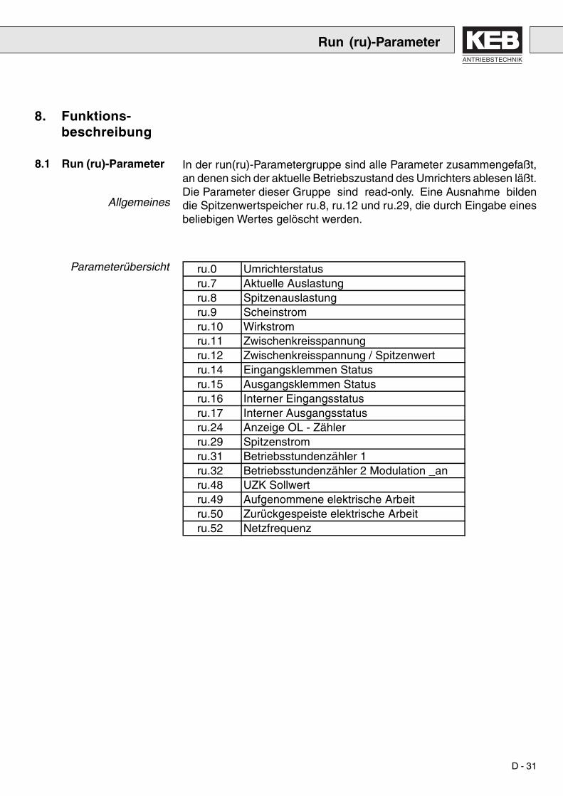
In der run(ru)-Parametergruppe sind alle Parameter zusammengefaßt,an denen sich der aktuelle Betriebszustand des Umrichters ablesen läßt.Die Parameter dieser Gruppe sind read-only. Eine Ausnahme bildendie Spitzenwertspeicher ru.8, ru.12 und ru.29, die durch Eingabe einesbeliebigen Wertes gelöscht werden.
8. Funktions-beschreibung
8.1 Run (ru)-Parameter
Allgemeines
Parameterübersicht
Run (ru)-Parameter
ru.0 Umrichterstatusru.7 Aktuelle Auslastungru.8 Spitzenauslastungru.9 Scheinstromru.10 Wirkstromru.11 Zwischenkreisspannung ru.12 Zwischenkreisspannung / Spitzenwertru.14 Eingangsklemmen Statusru.15 Ausgangsklemmen Statusru.16 Interner Eingangsstatusru.17 Interner Ausgangsstatusru.24 Anzeige OL - Zählerru.29 Spitzenstromru.31 Betriebsstundenzähler 1ru.32 Betriebsstundenzähler 2 Modulation _anru.48 UZK Sollwertru.49 Aufgenommene elektrische Arbeitru.50 Zurückgespeiste elektrische Arbeitru.52 Netzfrequenz

D - 32
Umrichterstatus (ru.0) Im Umrichterstatus (ru.0) wird der Betriebszustand des Umrichters an-gezeigt. Im folgenden werden die Bedeutungen der verschiedenen An-zeigen erklärt.
Anzeige Wert BedeutungnoP 0 No Operation: Reglerfreigabe nicht gebrückt,
Modulation abgeschaltetE.OP 1 Over Potention, Zwischenkreisspannung zu hochE.UP 2 Under Potention, Zwischenkreisspannung zu niedrigE.OC 4 Over Current, Ausgangsstrom > 2 * Inenn
(Constant torque)E.OH 8 Over Heat, Überhitzung des Inverters
E.dOH 9 Drossel Over Heat, Temperaturüberwachung derInduktivität hat ausgelöst und die Wartezeit ist ab-gelaufen
E.OL 16 Over Load, Überlastüberwachung des Invertershat angesprochen
E.nOL 17 No Over Load, Abkühlzeit nach E.OL ist abgelaufen,Fehler kann zurückgesetzt werden
E.buS 18 Watchdog ErrorE.EF 31 Extern Fault, Fehlermeldung durch externes Gerät
E.nOH 36 No Over Heat, Übertemperaturfehler liegt nicht mehran (E.OH oder E.dOH), Fehler kann zurückgesetztwerden
E.SEt 39 SatzanwahlfehlerE.PuC 49 Leistungsteilkennung ungültigE.SYn 115 Synchronisation fehlerhaft, z.B. Phasenzuordnung
nicht korrektE.net 122 Fehler nach Ablauf einer Verzögerungszeit (pn.59) bei
PhasenausfallE.rES 125 E.net wurde ausgelöst und die Wartezeit von 16 sec.
ist abgelaufen. Der Fehler kann nun zurückgesetztwerden.
bbl 76 Base-Block Zeit läuft ab, Wechselrichter freigeschaltetr4on 117 Modulation ist freigegeben, R4-F in Betrieb
(bei geringer Belastung)nEto 112 Phasenausfall bei ModulationfreigabeSYn 120 Synchronisiert auf den NetzwinkelPhau 119 Phasenausfall bei gesperrter Modulationinto 123 Einspeisung (motorischer Betrieb)retn 124 Rückspeisung (generatorischer Betrieb)
Run (ru)-Parameter

ANTRIEBSTECHNIK
D - 33
Der Parameter ru.7 gibt die aktuelle Auslastung des Umrichters in % an.100% bedeuten einen Ausgangsstrom der dem Nennstrom des Um-richters entspricht. Es werden nur positive Werte angezeigt, d.h. eineUnterscheidung, ob der Umrichter ein- oder rückspeist ist anhand vonru.7 nicht möglich.
ru.8 ermöglicht es, kurzfristige Spitzenauslastungen innerhalb einesBetriebszyklus zu erkennen. Dazu wird der höchste aufgetretene Wertvon ru.7 in ru.8 gespeichert. Der Spitzenwertspeicher kann durch Betä-tigen der Tasten UP oder DOWN sowie über Bus durch Schreiben einesbeliebigen Wertes an die Adresse von ru.8 gelöscht werden. Ein Ab-schalten des Umrichters führt ebenfalls zur Löschung des Speichers.
Unter ru.9 wird der aktuelle Scheinstrom mit einer Auflösung von 0,1Aangezeigt. Die Auflösung über Bus beträgt ebenfalls 0,1A.
ru.10 zeigt den aktuellen Wirkstrom an.
Unter ru.11 wird der aktuelle Wert der Zwischenkreisspannung mit einerAuflösung von 1V angezeigt. Der höchste Wert wird in ru.12 gespei-chert. ru.12 wird über Tastatur durch Betätigen der Tasten UP oder DOWNgelöscht. Über Bus kann der Spitzenwertspeicher durch Schreiben ei-nes beliebigen Wertes nach ru.12 gelöscht werden.
Aktuelle Auslastung (ru. 7)
Spitzenauslastung (ru.8)
Scheinstrom (ru.9)
Wirkstrom (ru.10)
Zwischenkreisspannung(ru.11, ru.12)
ru.14 zeigt den logischen Zustand der Eingangsklemmen an. LogischeVerknüpfungen, Strobe oder Flankentriggerung, werden nicht berück-sichtigt.
Eingangsklemmen Status(ru.14)
Bit - Nr. Dezimalwert Eingang Klemme
0 1 ST (Reglerfreigabe) 8
1 2 RST (Reset) 11
4 16 I1 (Prog. Eingang 1) 5
Ist ein Eingang angesteuert, so wird der zugehörige Dezimalwert ange-zeigt. Sind mehrere Eingänge angesteuert, so wird die Summe derDezimalwerte angezeigt.
Run (ru)-Parameter

D - 34
Ausgangsklemmen Status(ru.15)
ru.15 ermöglicht die Kontrolle der digitalen Ausgänge. ru.15 berücksich-tigt die logischen Verknüpfungen der digitalen Ausgänge (do. 0, do. 9 bisdo.25). Für jeden aktiven Ausgang wird der zugehörige Dezimalwertangezeigt. Sind mehrere Ausgänge aktiv, wird die Summe der Dezimal-werte angezeigt.
Bit - Nr. Dezimalwert Ausgang Klemmen
0 1 Out 1 (Transistorausgang) 12
1 2 Out 2 (Relais RLA,RLB,RLC) 1, 2, 3
2 4 Out 3 (Relais FLA,FLB,FLC) 21, 22, 23
4 16 Out A (Interner Ausgang A) keine
5 32 Out B (Interner Ausgang B) keine
6 64 Out C (Interner Ausgang C) keine
7 128 Out D (Interner Ausgang D) keine
Interner Eingangsstatus(ru.16)
ru.16 zeigt den logischen Zustand der digitalen Eingänge, Eingangs-klemmen, Flankentriggerung und logischer Verknüpfung durch die di -Parameter und internen Softwareeingänge IA bis ID an. Abhängig vonru.16 werden die in di.3 bis di.8 programmierten Funktionen ausgeführt.
Bit -Nr. Dezimalwert Eingang Klemme
0 1 ST (Reglerfreigabe) 8
1 2 RST (Reset) 11
4 16 I1 (Prog. Eingang 1) 5
8 256 IA (Interner Eingang A) keine
9 512 IB (Interner Eingang B) keine
10 1024 IC (Interner Eingang C) keine
11 2048 ID (Interner Eingang D) keine
Ist ein Eingang angesteuert, so wird der zugehörige Dezimalwert ange-zeigt. Sind mehrere Eingänge angesteuert, so wird die Summe derDezimalwerte angezeigt.
Run (ru)-Parameter

ANTRIEBSTECHNIK
D - 35
Bit - Nr. Dezimalwert Ausgangsschaltbedingung
0 1 Out1 Condition (do. 1)
1 2 Out2 Condition (do. 2)
2 4 Out3 Condition (do. 3)
3 8 Out4 Condition (do. 4)
Interner Ausgangsstatus(ru.17)
Anzeige OL -Zähler(ru.24)
ru.17 zeigt die Ergebnisse der Ausgangsfunktionstabellen (do. 1 bis do.3) an. Ist eine Schaltbedingung erfüllt, wird der zugehörige Dezimalwertangezeigt. Sind mehrere Schaltbedingungen erfüllt, wird die Summe derDezimalwerte angezeigt.
Mit Hilfe dieses Parameters kann die Dauerbelastung des Umrichtersausgewertet werden, um das Auftreten von OL zu vermeiden (rechtzei-tige Lastreduzierung). Der Fehler OL wird ausgelöst, wenn der OL- Zäh-ler 100% erreicht hat. Der Zählerstand wird mit 0.1 % Auflösung ange-zeigt.
Maximaler während einer Betriebsdauer aufgetretener Motorstrom (an-gezeigt in A). Der Spitzenwert kann durch Betätigen der Taste UP oderder Taste DOWN gelöscht werden. Ein Abschalten des Umrichters führtebenfalls zur Löschung des Speichers.
ru.29 zeigt die aktuelle Kühlkörpertemperatur in °C an. Die Auflösungbeträgt 1°C. Unterhalb von 20 °C wird noF angezeigt.
ru.31 gibt mit einer Auflösung von 1 Std. die Zeit, an die der Umrichterinsgesamt eingeschaltet (spannungsversorgt) war.
Scheinstrom/Spitzenwert(ru.25)
Kühlkörpertemperatur(ru.29)
Betriebsstundenzähler 1(ru.31)
Run (ru)-Parameter

D - 36
Betriebsstundenzähler 2(ru.32)
elektr. Arbeit into (ru.49)
elektr. Arbeit return (ru.50)
Netzfrequenz (ru.52)
ru.32 gibt mit einer Auflösung von 1 Std. die Zeit, an die der Umrichterinsgesamt aktiv (Modulation aktiv) war.
ru.49 gibt mit einer Auflösung von 1 kWh die elektrische Arbeit an, diedem Netz entnommen wurde. Die Genauigkeit der Anzeige ist u.a. ab-hängig von der Oberschwingungsbelastung der Netzspannung, da nurder Scheitelwert der Netzspannung ermittelt wird und somit der errech-nete Effektivwert vom realen Wert abweicht. Hinzu kommt die Ungenau-igkeit der Messwerterfassung. Über Bus kann der Parameter durch Über-schreiben mit dem Wert 0 gelöscht werden.
ru.50 gibt mit einer Auflösung von 1 kWh die elektrische Arbeit an, die indas Netz eingespeist wurde. Die Genauigkeit der Anzeige ist u.a. ab-hängig von der Oberschwingungsbelastung der Netzspannung, da nurder Scheitelwert der Netzspannung ermittelt wird und somit der errech-nete Effektivwert vom realen Wert abweicht. Hinzu kommt die Ungenau-igkeit der Messwerterfassung. Über Bus kann der Parameter durch Über-schreiben mit dem Wert 0 gelöscht werden.
ru.52 gibt mit einer Auflösung von 0.1 Hz die aktuelle Netzfrequenz an.
Run (ru)-Parameter

ANTRIEBSTECHNIK
D - 37
8.2 Protection (Pn) -Parameter
Parameterübersicht
Bei aktivierter Funktion wird der jeweilige Fehler automatisch zurückge-setzt.
Wert Bedeutung
0 Funktion abgeschaltet
1 Funktion eingeschaltet
Mit diesem Parameter kann das Auslösen des Fehlers E.dOH (Vorschalt-induktivität) nach Anliegen des externen Signals verzögert werden.
AutomatischerWiederanlauf
UP (Pn.0)OP (Pn.1)OC (Pn. 2)
Abschaltzeit E.doH(Pn.16)
Protection (Pn)-Parameter
Pn.0 Automatischer Wiederanlauf UPPn.1 Automatischer Wiederanlauf OPPn.2 Automatischer Wiederanlauf OCPn.16 Abschaltzeit Fehler E.dOHPn.23 Reaktion auf WatchdogPn.25 Reaktion auf dOH-FehlerPn.26 Reaktion auf OH-FehlerPn.59 Abschaltzeit E.NetPn.61 Automatischer Wiederanlauf E.NET
(Pn.23, Pn.25, Pn.26) Wert Reaktion Combivis Anzeige0 Fehlermeldung: E.xx sofortiges 0: Fehler/Neustart
Abschalten der Modulation. nach ResetFür den Wiederanlauf Fehlerbeseitigen und Reset betätigen.
3 Statusmeldung: A.xx sofortiges 3: Modulation aus/Abschalten der Modulation. autom.NeustartAutomatischer Wiederanlauf,wenn Fehlerbedingung nicht mehranliegt.
6 Statusmeldung: keine Auswirkung 6: Schutzfunktion ausauf den Umrichter Störung wird (keine Reaktion)ignoriert.
D - 38
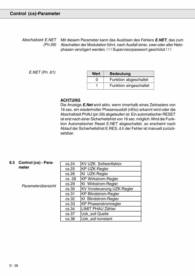
Abschaltzeit E.NET(Pn.59)
Mit diesem Parameter kann das Auslösen des Fehlers E.NET, das zumAbschalten der Modulation führt, nach Ausfall einer, zwei oder aller Netz-phasen verzögert werden. ! ! ! Supervisorpasswort geschützt ! ! !
8.3 Control (cs) - Para-meter
Parameterübersicht
Control (cs)-Parameter
E.NET (Pn .61) Wert Bedeutung
0 Funktion abgeschaltet
1 Funktion eingeschaltet
ACHTUNGDie Anzeige E.Net wird aktiv, wenn innerhalb eines Zeitrasters von16 sec. ein wiederholter Phasenausfall (nEto) erkannt wird oder dieAbschaltzeit PhAU (pn.59) abgelaufen ist. Ein automatischer RESETist erst nach einer Sicherheitsfrist von 16 sec. möglich. Wird die Funk-tion Automatischer Reset E.NET abgeschaltet, so erscheint nachAblauf der Sicherheitsfrist E.RES, d.h der Fehler ist manuell zurück-setzbar.
cs.24 KV UZK Sollwertfaktorcs.25 KP UZK-Reglercs.26 KI UZK-Reglercs. 28 KP Wirkstrom-Reglercs.29 KI Wirkstrom-Reglercs.30 KV Vorsteuerung UZK-Reglercs.31 KP Blindstrom-Reglercs.32 KI Blindstrom-Reglercs.33 KP Phasenstromreglercs.34 LIMIT PHAU Zählercs.37 Uzk_soll Quellecs.38 Uzk_soll konstant

ANTRIEBSTECHNIK
D - 39
KV UZK-Sollwert (cs.24)
KP UZK-Regler (cs.25)
KI UZK-Regler (cs.26)
KP Wirkstrom-Regler(cs.28)
KI Wirkstrom-Regler(cs.29)
KV Vorsteuerung UZK-Regler (cs.30)
KP Blindstrom-Regler(cs.31)
KI Blindstrom-Regler(cs.32)
KP Phasenstrom-Regler(cs.33)
Der Zwischenkreisspannungssollwert ist proportional zum Scheitelwertder verketteten Netzspannung.
Bestimmt die Verstärkung des Proportionalanteils des Zwischenkreis-spannungs-Reglers (UZK-Regler).
Bestimmt die Verstärkung des Integralanteils des UZK-Reglers.
Bestimmt die Verstärkung des Proportionalanteils des Wirkstrom-Reg-lers.
Bestimmt die Verstärkung des Integralanteils des Wirkstrom-Reglers.
Der Zwischenkreisstrom dient zur Vorsteuerung des UZK-Reglers. Mitdiesem Faktor können die Spannungsschwankungen im Zwischenkreiswährend dynamischer Vorgänge minimiert werden.
Bestimmt die Verstärkung des Proportionalanteils des Blindstrom-Reg-lers.
Bestimmt die Verstärkung des Integralanteils des Blindstrom-Reglers.
Bestimmt die Verstärkung des Proportionalanteils der Phasenstromregler.
Control (cs)-Parameter

D - 40
Limit PHAU Zähler(cs.34)
Uzk_soll Konstant (cs.38)
Uzk_soll Quelle (cs.37)
Bestimmt die Grenze für das Auslösen eines Phasenausfalls (nEto). Soll-te es im Betrieb trotz optimaler Reglerparametrierung (kp Phasenstrom-regler cs.33 ) zu Fehlermeldungen kommen, so kann dies durch Erhö-hung des Parameters vermieden werden. Durch Schreiben des Wertes0, wird die Funktion „Phasenausfallerkennung“ während derModulationsfreigabe ausgeschaltet.
Bestimmt die Quelle des Sollwertes für die Spannung Uzk.
Wert Bedeutung
0 Uzk_soll (CS.38)
1 Uzk_soll = f(Ûnetz . CS.24)
Vorgabe eines konstanten Sollwertes für die Zwischenkreisspannung.
Control (cs)-Parameter

ANTRIEBSTECHNIK
D - 41
Bei der Inbetriebnahme des KEB Combivert R4-F muß der Zwischen-kreisspannungsregler (Uzk-Regler) eingestellt werden. Dazu kann mitdem Gerät ein Sollwertsprung mit Hilfe des PC-Programms KEB-COMBIVIS aufgezeichnet werden.
· Parameter cs.30 = 0 setzen (Wert merken!).
· Programm KEB-COMBIVIS auf dem PC installieren und starten. MitF8 das Programm INVERTER SCOPE auswählen und starten.
· INVERTER SCOPE parametrieren:
Betriebsart: Offline
Zeitraster: 2 ms
Triggerposition: 5%
Triggerbedingung:1: ST
Kanal 1: ru.11
Kanal 2: ru.48
· Mit F3 in den Betriebsmodus von INVERTER SCOPE gehen, Kanälekalibrieren und Zeitbasis (z.B. 25ms / DIV) einstellen.
· F5 drücken; das INVERTER SCOPE ist betriebsbereit.
· Reglerfreigabe einschalten.
· Aufzeichnung UZK-Sollwertsprung stoppt nach einiger Zeit automa-tisch.
· Aufzeichnung mit Beispielen auf der nächsten Seite vergleichen undUZK-Reglerparameter entsprechend verstellen.
· Sollwertsprung wiederholen und erneut aufzeichen bis ein saubererEinschwingvorgang und damit optimale Reglerparameter gefundensind.
8.3.1 Abgleich desZwischenkreis-spannungsreglers
Control (cs)-Parameter

D - 42
Problem: Dauerschwingung mit hoherAmplitude
Abhilfe: I-Anteil (CS.26) reduzieren
Problem: zu langsamer Einschwingvorgang/ bleibende Regelabweichung
Abhilfe: I-Anteil (CS.26) erhöhen
Problem: sehr langer EinschwingvorgangAbhilfe: P-Anteil (CS.25) erhöhen;
evtl. I-Anteil (CS.26) reduzieren
Problem: zu hoher SpannungsüberschwingerAbhilfe: P-Anteil (CS.25) erhöhen;
evtl. I-Anteil (CS.26) reduzieren
Problem: zu langer ÜberschwingerAbhilfe: I-Anteil (CS.26) erhöhen
Problem: Dauerschwingung bei Konstantlauf
Abhilfe: P-Anteil (CS.25) reduzieren
8.3.2 Einstellhilfe Zwischenkreisspannungsregler
Control (cs)-Parameter

ANTRIEBSTECHNIK
D - 43
Um Zwischenkreisspannungsschwankungen durch Lastschwankungenzu minimieren, kann der Parameter cs.30 (kv Vorsteuerung UZK-Reg-ler) angepaßt werden. Sollte das Ergebnis nicht zufriedenstellen, sinddie Wirkstrom-Regelparameter cs.28 und cs.29 zu erhöhen.
Aber Achtung: Regelsystem kann ins Schwingen geraten.
Um Abweichungen des Stromverlaufes von der Sinusform auszuregeln,muss der Parameter cs.33 (kp Phasenstromregler) angepaßt werden.Wenn kein Oscilloscope zur Verfügung steht, um den Netzstrom darzu-stellen, kann ersatzweise der Parameter ru.9 (Scheinstrom) benutzt wer-den. Dabei gilt :
Je geringer die Schwankung bei konstanter Belastung, destosinusförmiger der Stromverlauf.
8.3.3 Dynamik verbessern
8.3.4 Stromverlauf opti-mieren
8.4 Drive (ds)-Parameter
Parameterübersicht
Schaltfrequenz (ds.13)
8.5 Free-programmable(Fr) Parameter
Parameterübersicht
Der Parameter ds.13 ist ein Initialisierungsparameter, d.h. neueParameterwerte werden erst nach Ausschalten des Gerätes aktiv.
Eine Erhöhung der Schaltfrequenz von 8 kHz auf 16 kHz hat eineErhöhung der Schaltverluste und damit eine Reduzierung der Nenn-leistung des COMBIVERT R4-F zur Folge. Außerdem muß die Vor-schaltinduktivität und der Filter auf die Schaltfrequenz von 16 kHzausgelegt sein.
Die Funktion init.def kopiert die im EPROM gespeicherten Grundein-stellungen in den SATZ 0, d.h. es werden auch die Regelparameterder CS-Gruppe mit ihren Defaultwerten geladen.
Folgende Einschränkung gilt für das Kopieren des Satzes:init kann nur bei ‘noP’ oder ‘syn’ ausgeführt werden.
Satz kopieren (Fr.0, Fr.1)
Drive (ds)-Parameter / Free-programmable (Fr)-Parameter
ds.13 Schaltfrequenz
Fr.0 Parametersatz kopieren (Tastatur)Fr.1 Parametersatz kopieren (Bus)

D - 44
8.6 User Definition(ud)-Parameter
Parameterübersicht
Tastaturpasswort (ud.0) Durch die Eingabe des entsprechenden Passwortes kann zwischen deneinzelnen Passwortebenen umgeschaltet werden. Die über diesen Pa-rameter eingestellte Passwortebene bezieht sich nur auf Eingaben überdie Tastatur, sowie die Anzeigen des LED-Displays. Die unabhängigenPasswortebenen für die Bedienung über serielle Schnittstelle oder dasDual-Port-Ram Protokoll werden über den Parameter ud.1 vorgegeben.Die Passwörter lauten:
Passwort Passwortebene
100 CP - READ-ONLY
200 CP - ON
330 CP - SERVICE
440 APPLICATION
xxx SUPERVISOR
Die Bedeutung der einzelnen Passwortebenen ist in Kapitel 6.5Passwortstruktur beschrieben. Wenn durch Betätigung der Taste FUNCTin die Parameterwertanzeige von ud.0 gewechselt wird, so wird zuerstdie aktuelle Passwortebene angezeigt. Um ein neues Passwort einzu-geben, wird mit UP/DOWN das neue Passwort eingestellt. Dieses mußmit ENTER bestätigt werden. Danach wird erneut die aktuelle Passwort-ebene angezeigt.
User Definition (ud)-Parameter
ud.0 Tastaturpasswortud.1 Buspasswortud.2 Startparameternummerud.3 Startparameternummerud.6 Umricher-Adresseud.7 Baudrateud.8 Watchdog timeud.15 CP.1 Adresseud.17 CP.2 Adresse*****ud.53 CP.20 Adresseud.55 CP.21 Adresseud.57 CP.22 Adresseud.59 CP.23 Adresseud.61 CP.24 Adresse

ANTRIEBSTECHNIK
D - 45
Das Tastaturpasswort kann auch über die serielle Schnittstelle oder dasDual-Port-Ram Protokoll vorgegeben werden. Diese Eingabe entsprichtder Eingabe über die Tastatur, d.h. nach der Vorgabe des Passwortesüber Bus zeigt das LED-Display die aktuelle Tastaturpasswortebene anund wechselt bei Betätigung von FUNCT zu ud.0 bzw. cP.0.
Über das Buspasswort ud. 1 werden die Passwortebenen für die Bedie-nung über serielle Schnittstelle bzw. Dual-Port-Ram Protokoll vorgege-ben. Es sind die Passwortebenen CP-ON, APPLICATION undSUPERVISOR möglich. Die Passwörter und die Bedeutung der Passwort-ebenen entsprechen denen des Tastaturpasswortes. Das Buspasswortist bei Tastaturbedienung nicht sichtbar.
Mit den Parametern Startparametergruppe und Startparameternummerwird der Parameter ausgewählt, der nach dem Einschalten des Um-richters angezeigt wird. Dazu wird in ud.2 die gewünschte Parameter-gruppe eingestellt, in ud.3 die gewünschte Parameternummer. DerParametersatz ist immer Satz 0. Ergibt die Kombination von ud.2 undud.3 einen Parameter der nicht vorhanden ist oder reicht der beim Ein-schalten aktuelle Passwortlevel nicht aus, um den Parameter anzuzei-gen, so startet der Umrichter mit der Anzeige von ru.0.
Ist beim Einschalten des Umrichters ein Passwortlevel < 3 aktiv, d.h.Anzeige der benutzerdefinierten Parametergruppe, so wird die Einstel-lung von ud.2 ignoriert. ud.3 gibt dann die Parameternumer des cP-Parameters an, dessen Wert beim Start dargestellt werden soll. Ist die-ser Parameter nicht vorhanden, so wird cP.0 angezeigt.
Über ud.6 wird die Adresse eingestellt, unter der der Umrichter von „KEBCOMBIVIS“ oder einer anderen Steuerung angesprochen wird. Es sindWerte zwischen 0 und 239 möglich, der Standardwert beträgt 1. Wennmehrere Umrichter gleichzeitig am Bus betrieben werden, ist es unbe-dingt erforderlich, ihnen unterschiedliche Adressen zuzuweisen, da essonst zu Kommunikationsstörungen kommt, weil unter Umständen meh-rere Umrichter gleichzeitig antworten. Weitere Informationen sind in derBeschreibung des DIN66019-Protokolls enthalten.
Buspasswort (ud.1)
Startparameter
(ud.2, ud.3)
Umrichter-Adresse (ud.6)
User Definition (ud)-Parameter

D - 46
Baudrate (ud.7)
Watchdog Zeit (ud.8)
Folgende Werte für die Baudrate der seriellen Schnittstelle sind mög-lich:
Parameterwert Baudrate
0 1200 baud
1 2400 baud
2 4800 baud
3 9600 baud
4 19200 baud
Wird der Wert für die Baudrate über die serielle Schnittstelle verändert,kann er nur über die Tastatur oder nach Anpassung der Baudrate desMasters wieder geändert werden, da bei unterschiedlichen Baudratenvon Master und Slave keine Kommunikation möglich ist.
Zur ständigen Kontrolle der Kommunikation ist es möglich, nach Ablaufeiner einstellbaren Zeit ohne eingehende Telegramme eine Fehlermel-dung des Umrichters auszulösen. Durch Einstellen des Wertes 0 (off)kann die Funktion deaktiviert werden.
8.7 Analog I/O (An)-Parameter
Parameterübersicht
Flußdiagramm analogeAusgänge
Kennlinienverstärker deranalogen Ausgänge
(An.15 - An.16)
Offset X
Offs
et Y
+100 %
+100 %
-100 %
-100 %
Ausgangswert
GAINAn.15
An.16
EingangswertAn.14
AN-OUTAn.15An.16
An.14
Analog I/O (An)-Parameter
An.14 Analogausgang 1 FunktionAn.15 Analogausgang 1 VerstärkungAn.16 Analogausgang 1 Offset X

ANTRIEBSTECHNIK
D - 47
Die Steigung der Kennlinie wird durch die Verstärkung (An.15) bestimmt.Der Offset X (An.16) wird benötigt, wenn Signalschwankungen um ei-nen Grundwert visualisiert werden sollen (z.B. Istwert der Zwischen-kreisspannung gegen Sollwert der Zwischenkreisspannung). Vorgabein [%], Auflösung 0,1%.
Analogausgang 1Funktion (An.14)
Analogausgang 1(An.15, An.16)
Mit diesem Parameter kann die Größe ausgewählt werden, die überden analogen Ausgang dargestellt werden soll. Die Auflösung der Analog-werte beträgt 10 Bit, die Glättungszeitkonstante für die Analogsignalebeträgt ca. 5 ms.
Parameterwert Prozessgröße Wert bei 100%
0 akt. Auslastung 200%
1 Zwischenkreisspannung 1000 V
8.8 Digital Input (di)-Parameter
Parameterübersicht
Digital Input (di)-Parameter
di.0 Digitales Störfilterdi.1 NPN / PNP Auswahldi.2 Eingangslogikdi.3 Eingangsfunktion I1di.7 Eingangsfunktion IAdi.8 Eingangsfunktion IBdi.9 Eingangsfunktion ICdi.10 Eingangsfunktion IDdi.15 Signalquellenauswahldi.16 Digitale Eingangswahl

D - 48
ru. 14
di. 0 di. 2
ru. 16
di. 15di. 16
Mit diesem Parameter wird die Ansteuerlogik der Steuereingänge ein-gestellt.
Parameterwert Logik der Eingangsklemmen
0 NPN
1 PNP
Eingangsbearbeitung
Digitales Störfilter (di.0)
NPN/PNP-Auswahl (di.1)
Das digitale Filter reduziert die Empfindlichkeit gegenüber Störungenan den Steuereingängen. Mit dem Parameter wird die Reaktionszeit derEingänge eingestellt. Während der Reaktionszeit muß ein konstanterEingangsstatus an allen Eingängen anliegen, bevor ein Signal als gül-tig übernommen wird.
Signale an derSteuerklemmleiste
Steuerungsinterne Signaleohne Digitalfilter
Steuerungsinterne Signale/16 ms Digitalfilter
Steuer-klemm-leiste
Parameter
Abtastung
Eingangs-klemmen-
status
AuswahlSignalquelle
Digitalfilter Eingangs-logik
InternerEingangs-
status
Prozesseingang
11 t4 ms
I1
RST
10987654321
pos. Flanke =Abtastzeitpunkt fürdie EingangssignaleFilterzeit 16 ms
Digital Input (di)-Parameter

ANTRIEBSTECHNIK
D - 49
Bitcodierte Parameterdi.2, di.14 - di.18
Eingangsfunktionen(di.3 - di.10)
Eingangslogik (di.2)
Bei den bitcodierten di-Parametern wird für jeden Eingang, für den dieentsprechende Funktion aktiviert werden soll, der zugehörige Dezimal-wert eingestellt. Soll die Funktion für mehrere Eingänge gelten, wird dieSumme der Dezimalwerte eingestellt. Für den Eingang ST gelten Aus-nahmen, die bei den einzelnen Parametern beschrieben sind. Es giltfolgende Zuordnung:
Bit - Nr. Dezimalwert Eingang
0 1 ST
1 2 RST
4 16 I1
Mit diesem Parameter wird eingestellt, ob ein Eingangssignal 1- oder 0-aktiv (invertiert) ist. Eingang ST wird nicht invertiert!
Mit diesen Parametern wird die Funktion der programmierbaren Ein-gänge (I1 bis I4), und der programmierbaren Softwareeingänge (IA, IB,IC, ID) eingestellt.
Parameterwert Eingangsfunktion
0 keine Funktion
1 Eingang löst externen Fehler (E.EF) aus
Im Parameter di.15 kann für jeden Eingang ausgewählt werden, ob derStatus der Steuerklemmleiste oder der Status des Parameters di.16ausgewertet wird.
Über di.16 können Eingänge über Software gesetzt werden. Hierzumüssen die entsprechenden Eingänge in di.15 ausgewählt sein.
Der Eingang ST bildet eine Ausnahme. Falls digitale Vorgabe der Regler-freigabe eingestellt ist (Bit 0 von di.15 = 1), muß das Signal über dieKlemmleiste und über Parameter di.16 (Bit 0) vorgegeben werden.
Signalquellenauswahl(di.15)
Digitale Eingangsanwahl(di.16)
Digital Input (di)-Parameter

D - 50
Steuerklemmleiste ST
RST
I1
Bit 0
Bit 1
Bit 2
Bit 3
Bit 4
Bit 5
Bit 6
di.16
Steuerklemmleiste
Bit 1
Bit 2
Bit 3
Bit 4
Bit 5
Bit 6
di.15Bit 0
ST
RST
I1
Bit 7
Bit 7
Digital Input (di)-Parameter

ANTRIEBSTECHNIK
D - 51
Ausgangslogik (do.0) Bit - Nr. Dezimalwert Ausgang Klemmen
0 1 Out 1 (Transistorausgang) 12
1 2 Out 2 (Relais RLA,RLB,RLC) 1, 2, 3
2 4 Out 3 (Relais FLA,FLB,FLC) 21, 22, 23
4 16 Out A (Interner Ausgang A) keine
5 32 Out B (Interner Ausgang B) keine
6 64 Out C (Interner Ausgang C) keine
7 128 Out D (Interner Ausgang D) keine
Für jeden Ausgang, der invertiert werden soll, wird der zugehörigeDezimalwert eingestellt. Sollen mehrere Ausgänge invertiert werden,wird die Summe der Dezimalwerte eingestellt.
8.9 Digital Output (do)-Parameter
Parameterübersicht
Die Ausgangslogik ermöglicht das Invertieren der digitalen Ausgänge.Der Parameter ist bitcodiert.
Digital Output (do)-Parameter
do.0 Ausgangslogikdo.1 Schaltbedingung 1do.2 Schaltbedingung 2do.3 Schaltbedingung 3do.4 Schaltbedingung 4do.9 Auswahl Schaltbedingung Ausgang Out 1 do.10 Auswahl Schaltbedingung Ausgang Out 2do.11 Auswahl Schaltbedingung Ausgang Out 3do.13 Auswahl Schaltbedingung Ausgang Out Ado.14 Auswahl Schaltbedingung Ausgang Out Bdo.15 Auswahl Schaltbedingung Ausgang Out Cdo.16 Auswahl Schaltbedingung Ausgang Out Ddo.17 Logik Schaltbedingung Ausgang Out 1do.18 Logik Schaltbedingung Ausgang Out 2do.19 Logik Schaltbedingung Ausgang Out 3do.21 Logik Schaltbedingung Ausgang Out Ado.22 Logik Schaltbedingung Ausgang Out Bdo.23 Logik Schaltbedingung Ausgang Out Cdo.24 Logik Schaltbedingung Ausgang Out Ddo.25 Verknüpfung der Schaltbedingungen

D - 52
Bit-Nr. Dezimalwert Schaltbedingung
0 1 do.1
1 2 do.2
2 4 do.3
3 8 do.4
Es können auch mehrere Bedingungen für einen Ausgang gelten. In die-sem Fall sind die Summen der Dezimalwerte einzustellen.
Vom Erreichen eines bestimmten Betriebszustandes des Umrichters(z.B. Scheinstrom > Scheinstrom Level) bis zur Generierung desentsprechenden Ausgangssignals kann eine Verarbeitungszeit voneinigen ms vergehen.
Um eine Schaltbedingung für den entsprechenden Ausgang zu aktivie-ren, wird der jeweilige Dezimalwert im Parameter „Auswahl Schalt-bedingung Out X“ eingestellt. Der Zustand der Schaltbedingungen wirdin Parameter ru.17 angezeigt. Jede Schaltbedingung kann durch Ein-stellen des entsprechenden Dezimalwertes im Parameter „Logik derSchaltbedingungen Out X“ invertiert werden.
Schaltbedingung 4(do.1 - do.4)
Mit diesen Parametern werden die Schaltbedingungen eingestellt, dieüber die Parameter do.9 bis do.25 den Ausgängen Out 1 bis Out 3 undden internen Ausgängen Out A bis Out D zugeordnet werden:
Wert Funktion des Ausgangs
0 immer inaktiv
1 immer aktiv
2 Ready
3 Run
4 fatal error
5 Zwischenkreisspannung > Zwischenkreisspannungslevel
6 Scheinstrom > Scheinstrom-Level
7 Signal von PTC Vorschaltinduktivität
8 Signal von Kühlkörpertemperatur
9 Stromregler in der Begrenzung
10 Zwischenkreisspannungs-Regler in der Begrenzung
11 beliebiger Regler in der Begrenzung
12 Auslastung (ru.7) > Auslastungspegel (LE.8 ... LE.10 (15))
13 OL counter > 80%14 Phasenausfall
Auswahl Schaltbedingung(do.9 - do.11, do.13 - do.16)
Digital Output (do)-Parameter
ANTRIEBSTECHNIK
D - 53
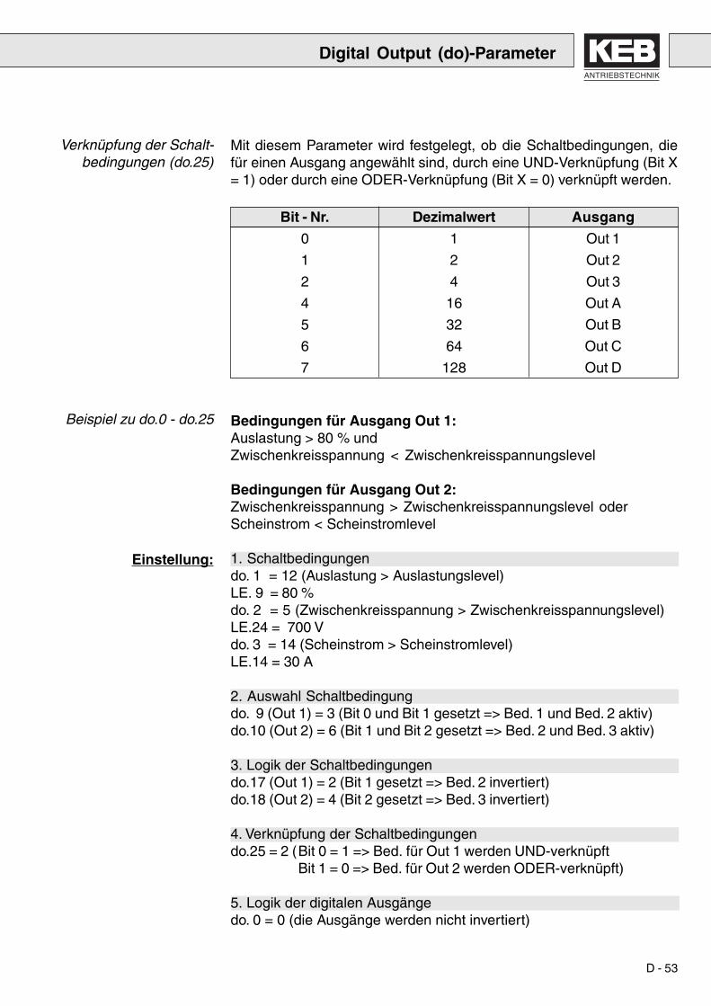
Verknüpfung der Schalt-bedingungen (do.25)
Beispiel zu do.0 - do.25
Einstellung:
Mit diesem Parameter wird festgelegt, ob die Schaltbedingungen, diefür einen Ausgang angewählt sind, durch eine UND-Verknüpfung (Bit X= 1) oder durch eine ODER-Verknüpfung (Bit X = 0) verknüpft werden.
Bit - Nr. Dezimalwert Ausgang
0 1 Out 1
1 2 Out 2
2 4 Out 3
4 16 Out A
5 32 Out B
6 64 Out C
7 128 Out D
Bedingungen für Ausgang Out 1:Auslastung > 80 % undZwischenkreisspannung < Zwischenkreisspannungslevel
Bedingungen für Ausgang Out 2:Zwischenkreisspannung > Zwischenkreisspannungslevel oderScheinstrom < Scheinstromlevel
1. Schaltbedingungendo. 1 = 12 (Auslastung > Auslastungslevel)LE. 9 = 80 %do. 2 = 5 (Zwischenkreisspannung > Zwischenkreisspannungslevel)LE.24 = 700 Vdo. 3 = 14 (Scheinstrom > Scheinstromlevel)LE.14 = 30 A
2. Auswahl Schaltbedingungdo. 9 (Out 1) = 3 (Bit 0 und Bit 1 gesetzt => Bed. 1 und Bed. 2 aktiv)do.10 (Out 2) = 6 (Bit 1 und Bit 2 gesetzt => Bed. 2 und Bed. 3 aktiv)
3. Logik der Schaltbedingungendo.17 (Out 1) = 2 (Bit 1 gesetzt => Bed. 2 invertiert)do.18 (Out 2) = 4 (Bit 2 gesetzt => Bed. 3 invertiert)
4. Verknüpfung der Schaltbedingungendo.25 = 2 (Bit 0 = 1 => Bed. für Out 1 werden UND-verknüpft
Bit 1 = 0 => Bed. für Out 2 werden ODER-verknüpft)
5. Logik der digitalen Ausgängedo. 0 = 0 (die Ausgänge werden nicht invertiert)
Digital Output (do)-Parameter

D - 54
Parameterübersicht
8.10 Level (LE)-Parameter
Diese Parameter sind die Vergleichswerte für die auslastungs-abhängigen Schaltbedingungen der digitalen Ausgänge. Auslastungs-pegel 1 gilt für Schaltbedingung 1 usw.
Wertebereich: 0 ... 199 %Auflösung: 1 %
Diese Parameter sind die Vergleichswerte für die scheinstrom-abhängigen Schaltbedingungen der digitalen Ausgänge. Scheinstrom-pegel 1 gilt für Schaltbedingung 1 usw.
Wertebereich: 0 ... 150 AAuflösung: 0.1 A
Diese Parameter sind die Vergleichswerte für die zwischenkreis-spannungsabhängigen Schaltbedingungen der digitalen Ausgänge.Zwischenkreisspannungspegel 1 gilt für Schaltbedingung 1 usw.
Wertebereich: 0 ... 1000VAuflösung: 1V
Mit diesem Parameter wird die Höhe der Stromhysterese eingestellt.
Wertebereich: 0 ... 150 AAuflösung: 0.1A
Auslastungspegel 1-4(LE.8 - LE.11)
Scheinstrompegel 1-4(LE.12 - LE.15)
UZK-Pegel 1-4(LE.24 - LE.27)
Stromhysterese (LE.38)
Level (LE)-Parameter
LE.8 Auslastungspegel 1LE.9 Auslastungspegel 2LE.10 Auslastungspegel 3LE.11 Auslastungspegel 4LE.12 Scheinstrompegel 1LE.13 Scheinstrompegel 2LE.14 Scheinstrompegel 3LE.15 Scheinstrompegel 4LE.24 Zwischenkreisspannungspegel 1LE.25 Zwischenkreisspannungspegel 2LE.26 Zwischenkreisspannungspegel 3LE.27 Zwischenkreisspannungspegel 4LE.38 Stromhysterese

ANTRIEBSTECHNIK
D - 55
8.11 Information (In)-Parameter
Parameterübersicht
Invertertyp (In.0)
Information (In)-Parameter
Bit-Nr. Bedeutung0 Spannungsklasse 0 = 200 V, 1 = 400 V
1...5 Gerätegröße6...8 Steuerkartentyp 3 = OC.R4
9 Erweiterung10 frei
11...12 Max. Schaltfrequenz 0 = 2 kHz, 1 = 4 kHz,2 = 8 kHz, 3 = 16 kHz
13...15 Gehäusetyp = G = H = K= L = M = N= R = D
In.0 InvertertypIn.1 InverternennstromIn.3 max. SchaltfrequenzIn.4 Software - IdentifikationIn.5 Software - DatumIn.6 Config-File-Nr.In.7 Seriennummer (Datum)In.8 Seriennummer (Zähler)In.9 Seriennummer (AB-Nr. high)In.10 Seriennummer (AB-Nr. low)In.11 Kundennummer (high)In.12 Kundennummer (low)In.13 QS - NummerIn.40 Letzter FehlerIn.41 Fehlerzähler OCIn.42 Fehlerzähler OLIn.43 Fehlerzähler OPIn.44 Fehlerzähler OHIn.45 Fehlerzähler WD

D - 56
Software-Datum (In.5)
Configfile-Nummer (In.6)
Seriennummern,Kundennummer
(In.7 - In.12),QS-Nummer (In.13)
Fehlerzähler (In.40 - In.45)
Anzeige des Software-Datums. Der Wert setzt sich aus Tag, Monat undJahr zusammen, wobei von der Jahreszahl nur die letzte Ziffer ange-zeigt wird.Beispiel: Anzeige = 1507.4
Datum = 15.07.94
Dieser Parameter dient zur Identifikation der auf der Steuerung einge-setzten Software durch KEB COMBIVIS. Die Konfiguration erfolgt beimAufruf von COMBIVIS und angeschlossenem Umrichter automatisch.
Die Seriennummer und die Kundennummer identifizieren den Umrichter.Die QS-Nummer enthält produktionsinterne Informationen.
Die Fehlerzähler (für E.OC, E.OL, E.OP, E.OH, E.buS) geben die An-zahl der insgesamt aufgetretenen Fehler des jeweiligen Typs an. DerMaximalwert ist 255.
Information (In)-Parameter
Inverternennstrom (In.1)
Max. Schaltfrequenz (In.3)
Software-Identifikation(In.4)
Anzeige des Umrichternennstroms in A (Auflösung 0.1 A).
Anzeige der für diesen Umrichter maximal möglichen Schaltfrequenz inkHz (Auflösung 1 kHz).
In diesem Parameter ist die Software-Versionsnummer und dieSteuerungshardware verschlüsselt.

ANTRIEBSTECHNIK
D - 57
Parameterübersicht
9. Parameterübersicht
9.1 Tabelle ru-Parameter
Default-wert
Auflösung
EinheitParameteradresse
Obergrenze
Parameter: ja schreibbar– nur-lesbar
Parameter: ja nach „Enter“ aktiv– sofort aktiv
Untergrenze
Parameter Adr. min max Step default [?]
ru0 Umrichter Status 2000h – 0 200 Tabelle – –
ru7 Aktuelle Auslastung 2007h – 0 200 0,1 – %
ru8 Spitzenauslastung 2008h ja 0,1 – %
ru9 Scheinstrom 2009h – 0,1 – A
ru10 Wirkstrom 200Ah – 0,1 – A
ru11 Zwischenkreisspannung 200Bh – 1 – V
ru12 ZK-Spannungsspitzenwert 200Ch ja 1 – V
ru14 Eingangsklemmen Status 200Eh – Tabelle – –
ru15 Ausgangsklemmen Status 200Fh – Tabelle – –
ru16 Interner Eingangs Status 2010h – Tabelle – –
ru17 Interner Ausgangs Status 2011h – Tabelle – –
ru24 Anzeige OL-Zähler 2012h – 0,0 100 0,1 – %
ru25 Scheinstrom/Spitzenwert 2019h ja 0,1 – A
ru29 Kühlkörpertemperatur 201Dh – 0 100 1 – °C
ru31 Betriebsstundenzähler 1 201Fh – 0 65535 1 – h
ru32 Betriebsstundenzähler 2 2020h – 0 65535 1 – h
ru48 Act. ZK-Spg. Sollwert 2030h – – – 1 – V
ru49 Aufgenommene elek. Arbeit 2031h ja 0 65535 1 – kWh
ru50 Zurückgespeiste elek. Arbeit 2032h ja 0 65535 1 – KWh
ru52 Netzfrequenz 2034h – 45 65 0,1 – Hz
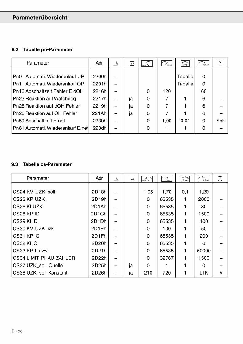
D - 58
9.2 Tabelle pn-Parameter
Parameterübersicht
Parameter Adr. min max Step default [?]
Pn0 Automati. Wiederanlauf UP 2200h – Tabelle 0
Pn1 Automati. Wiederanlauf OP 2201h – Tabelle 0
Pn16 Abschaltzeit Fehler E.dOH 2216h – 0 120 60
Pn23 Reaktion auf Watchdog 2217h – ja 0 7 1 6 –
Pn25 Reaktion auf dOH Fehler 2219h – ja 0 7 1 6 –
Pn26 Reaktion auf OH Fehler 221Ah – ja 0 7 1 6 –
Pn59 Abschaltzeit E.net 223bh – 0 1,00 0,01 0 Sek.
Pn61 Automati. Wiederanlauf E.net 223dh – 0 1 1 0 –
9.3 Tabelle cs-Parameter
Parameter Adr. min max Step default [?]
CS24 KV UZK_soll 2D18h – 1,05 1,70 0,1 1,20
CS25 KP UZK 2D19h – 0 65535 1 2000 –
CS26 KI UZK 2D1Ah – 0 65535 1 80 –
CS28 KP ID 2D1Ch – 0 65535 1 1500 –
CS29 KI ID 2D1Dh – 0 65535 1 100 –
CS30 KV UZK_izk 2D1Eh – 0 130 1 50 –
CS31 KP IQ 2D1Fh – 0 65535 1 200 –
CS32 KI IQ 2D20h – 0 65535 1 6 –
CS33 KP I_uvw 2D21h – 0 65535 1 50000 –
CS34 LIMIT PHAU ZÄHLER 2D22h – 0 32767 1 1500 –
CS37 UZK_soll Quelle 2D25h – ja 0 1 1 0 –
CS38 UZK_soll Konstant 2D26h – ja 210 720 1 LTK V

ANTRIEBSTECHNIK
D - 59
9.4 Tabelle ud-Parameter
Parameterübersicht
Parameter Adr. min max Step default [?]
ud0 Tastaturpasswort 2600h ja ja 0 9999 1 0 –
ud1 Buspasswort 2601h ja ja 0 9999 1 0 –
ud2 Startparametergruppe 2602h ja – ru Tabelle Tabelle ru –
ud3 Startparameternummer 2603h ja – 0 255 Tabelle 1 –
ud6 Umrichteradresse 2606h ja ja 0 239 1 1 –
ud7 Baudrate 2607h ja ja 1200 57600 Tabelle 9600 Baud
ud8 Watchdog Zeit 2608h ja ja 0 : off 10,00 0,01 0 : off Sek.
ud13 cP.0 Adresse 260Dh ja ja – – 1 2600 (cp.0) –
ud15 cP.1 Adresse 260Fh ja ja 0 7FFFF 1 2000 (ru.00) –
ud17 cP.2 Adresse 2611h ja ja -1 : off 7FFFF 1 200B (ru.11) –
ud19 cP.3 Adresse 2613h ja ja 0 7FFFF 1 200C (ru.12) –
ud21 cP.4 Adresse 2615h ja ja 0 7FFFF 1 2030 (ru.48) –
ud23 cP.5 Adresse 2617h ja ja 0 7FFFF 1 2D25 (cs.37) –
ud25 cP.6 Adresse 2619h ja ja 0 7FFFF 1 2D1C (cs.28) –
ud27 cP.7 Adresse 261Bh ja ja 0 7FFFF 1 2D1B (cs.27) –
ud29 cP.8 Adresse 261Dh ja ja 0 7FFFF 1 2D19 (cs.25) –
ud31 cP.9 Adresse 261Fh ja ja 0 7FFFF 1 2D1A (cs.26) –
ud33 cP.10 Adresse 2621h ja ja 0 7FFFF 1 2D20 (cs.32) –
ud35 cP.11 Adresse 2623h ja ja 0 7FFFF 1 2D1E (cs.30) –
ud37 cP.12 Adresse 2625h ja ja 0 7FFFF 1 2009 (ru.09) –
ud39cP.13 Adresse 2627h ja ja 0 7FFFF 1 2007 (ru.07) –
ud41 cP.14 Adresse 2629h ja ja 0 7FFFF 1 201B (ru.29) –
ud43 cP.15 Adresse 262Bh ja ja 0 7FFFF 1 280E (an.14) –
ud45 cP.16 Adresse 262Dh ja ja 0 7FFFF 1 280F (an.15) –
ud47 cP.17 Adresse 262Fh ja ja 0 7FFFF 1 2903 (di.03) –
ud49 cP.18 Adresse 2631h ja ja 0 7FFFF 1 2A01 (do.01) –
ud51 cP.19 Adresse 2633h ja ja 0 7FFFF 1 2A02 (do.02) –
ud53 cP.20 Adresse 2635h ja ja 0 7FFFF 1 2A09 (do.09) –
ud55 cP.21 Adresse 2637h ja ja 0 7FFFF 1 2A0A (do.10) –
ud57 cP.22 Adresse 2639h ja ja 0 7FFFF 1 2B08 (le.08) –
ud59 cP.23 Adresse 263Bh ja ja 0 7FFFF 1 2B0C (le.12) –
ud61 cP.24 Adresse 263Dh ja ja 0 7FFFF 1 2B18 (le. 24) –
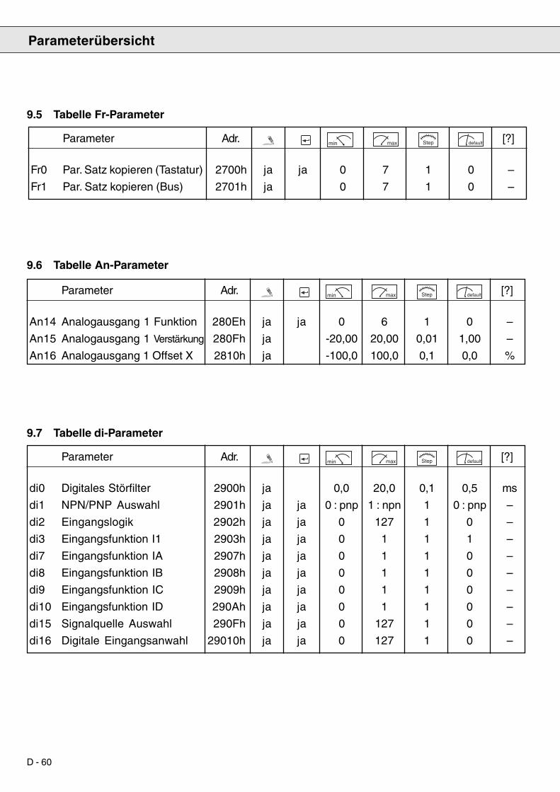
D - 60
9.5 Tabelle Fr-Parameter
9.6 Tabelle An-Parameter
9.7 Tabelle di-Parameter
Parameterübersicht
Parameter Adr. min max Step default [?]
Fr0 Par. Satz kopieren (Tastatur) 2700h ja ja 0 7 1 0 –
Fr1 Par. Satz kopieren (Bus) 2701h ja 0 7 1 0 –
Parameter Adr. min max Step default [?]
An14 Analogausgang 1 Funktion 280Eh ja ja 0 6 1 0 –
An15 Analogausgang 1 Verstärkung 280Fh ja -20,00 20,00 0,01 1,00 –
An16 Analogausgang 1 Offset X 2810h ja -100,0 100,0 0,1 0,0 %
Parameter Adr. min max Step default [?]
di0 Digitales Störfilter 2900h ja 0,0 20,0 0,1 0,5 ms
di1 NPN/PNP Auswahl 2901h ja ja 0 : pnp 1 : npn 1 0 : pnp –
di2 Eingangslogik 2902h ja ja 0 127 1 0 –
di3 Eingangsfunktion I1 2903h ja ja 0 1 1 1 –
di7 Eingangsfunktion IA 2907h ja ja 0 1 1 0 –
di8 Eingangsfunktion IB 2908h ja ja 0 1 1 0 –
di9 Eingangsfunktion IC 2909h ja ja 0 1 1 0 –
di10 Eingangsfunktion ID 290Ah ja ja 0 1 1 0 –
di15 Signalquelle Auswahl 290Fh ja ja 0 127 1 0 –
di16 Digitale Eingangsanwahl 29010h ja ja 0 127 1 0 –
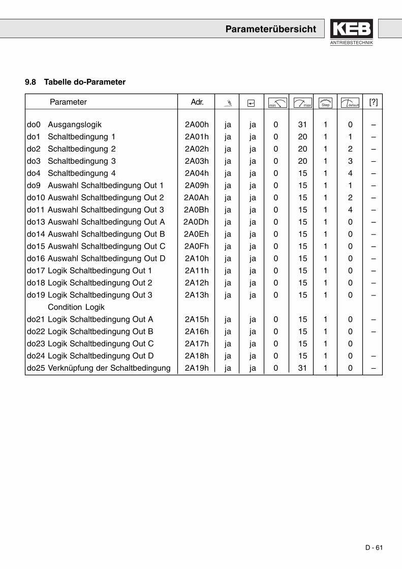
ANTRIEBSTECHNIK
D - 61
9.8 Tabelle do-Parameter
Parameterübersicht
Parameter Adr. min max Step default [?]
do0 Ausgangslogik 2A00h ja ja 0 31 1 0 –
do1 Schaltbedingung 1 2A01h ja ja 0 20 1 1 –
do2 Schaltbedingung 2 2A02h ja ja 0 20 1 2 –
do3 Schaltbedingung 3 2A03h ja ja 0 20 1 3 –
do4 Schaltbedingung 4 2A04h ja ja 0 15 1 4 –
do9 Auswahl Schaltbedingung Out 1 2A09h ja ja 0 15 1 1 –
do10 Auswahl Schaltbedingung Out 2 2A0Ah ja ja 0 15 1 2 –
do11 Auswahl Schaltbedingung Out 3 2A0Bh ja ja 0 15 1 4 –
do13 Auswahl Schaltbedingung Out A 2A0Dh ja ja 0 15 1 0 –
do14 Auswahl Schaltbedingung Out B 2A0Eh ja ja 0 15 1 0 –
do15 Auswahl Schaltbedingung Out C 2A0Fh ja ja 0 15 1 0 –
do16 Auswahl Schaltbedingung Out D 2A10h ja ja 0 15 1 0 –
do17 Logik Schaltbedingung Out 1 2A11h ja ja 0 15 1 0 –
do18 Logik Schaltbedingung Out 2 2A12h ja ja 0 15 1 0 –
do19 Logik Schaltbedingung Out 3 2A13h ja ja 0 15 1 0 –
Condition Logik
do21 Logik Schaltbedingung Out A 2A15h ja ja 0 15 1 0 –
do22 Logik Schaltbedingung Out B 2A16h ja ja 0 15 1 0 –
do23 Logik Schaltbedingung Out C 2A17h ja ja 0 15 1 0
do24 Logik Schaltbedingung Out D 2A18h ja ja 0 15 1 0 –
do25 Verknüpfung der Schaltbedingung 2A19h ja ja 0 31 1 0 –
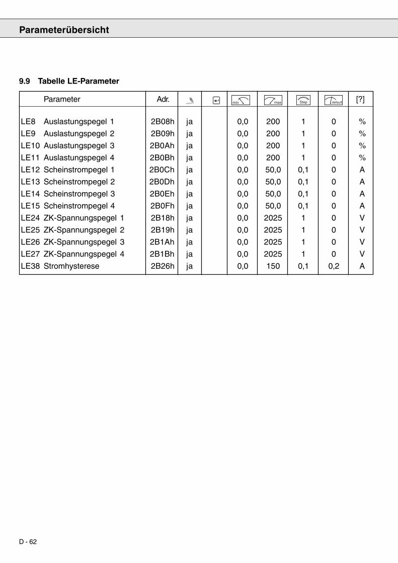
D - 62
Parameterübersicht
9.9 Tabelle LE-Parameter
Parameter Adr. min max Step default [?]
LE8 Auslastungspegel 1 2B08h ja 0,0 200 1 0 %
LE9 Auslastungspegel 2 2B09h ja 0,0 200 1 0 %
LE10 Auslastungspegel 3 2B0Ah ja 0,0 200 1 0 %
LE11 Auslastungspegel 4 2B0Bh ja 0,0 200 1 0 %
LE12 Scheinstrompegel 1 2B0Ch ja 0,0 50,0 0,1 0 A
LE13 Scheinstrompegel 2 2B0Dh ja 0,0 50,0 0,1 0 A
LE14 Scheinstrompegel 3 2B0Eh ja 0,0 50,0 0,1 0 A
LE15 Scheinstrompegel 4 2B0Fh ja 0,0 50,0 0,1 0 A
LE24 ZK-Spannungspegel 1 2B18h ja 0,0 2025 1 0 V
LE25 ZK-Spannungspegel 2 2B19h ja 0,0 2025 1 0 V
LE26 ZK-Spannungspegel 3 2B1Ah ja 0,0 2025 1 0 V
LE27 ZK-Spannungspegel 4 2B1Bh ja 0,0 2025 1 0 V
LE38 Stromhysterese 2B26h ja 0,0 150 0,1 0,2 A
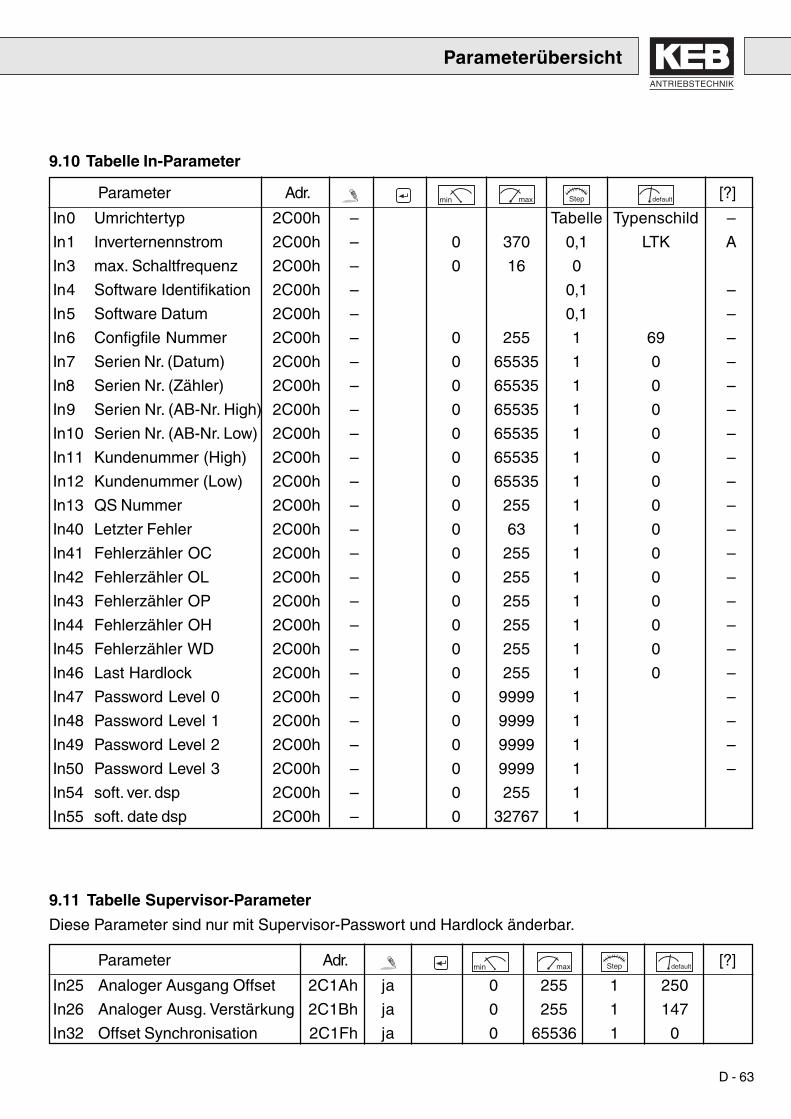
ANTRIEBSTECHNIK
D - 63
9.11 Tabelle Supervisor-Parameter
Diese Parameter sind nur mit Supervisor-Passwort und Hardlock änderbar.
9.10 Tabelle In-Parameter
Parameterübersicht
Parameter Adr. min max Step default [?]
In0 Umrichtertyp 2C00h – Tabelle Typenschild –
In1 Inverternennstrom 2C00h – 0 370 0,1 LTK A
In3 max. Schaltfrequenz 2C00h – 0 16 0
In4 Software Identifikation 2C00h – 0,1 –
In5 Software Datum 2C00h – 0,1 –
In6 Configfile Nummer 2C00h – 0 255 1 69 –
In7 Serien Nr. (Datum) 2C00h – 0 65535 1 0 –
In8 Serien Nr. (Zähler) 2C00h – 0 65535 1 0 –
In9 Serien Nr. (AB-Nr. High) 2C00h – 0 65535 1 0 –
In10 Serien Nr. (AB-Nr. Low) 2C00h – 0 65535 1 0 –
In11 Kundenummer (High) 2C00h – 0 65535 1 0 –
In12 Kundenummer (Low) 2C00h – 0 65535 1 0 –
In13 QS Nummer 2C00h – 0 255 1 0 –
In40 Letzter Fehler 2C00h – 0 63 1 0 –
In41 Fehlerzähler OC 2C00h – 0 255 1 0 –
In42 Fehlerzähler OL 2C00h – 0 255 1 0 –
In43 Fehlerzähler OP 2C00h – 0 255 1 0 –
In44 Fehlerzähler OH 2C00h – 0 255 1 0 –
In45 Fehlerzähler WD 2C00h – 0 255 1 0 –
In46 Last Hardlock 2C00h – 0 255 1 0 –
In47 Password Level 0 2C00h – 0 9999 1 –
In48 Password Level 1 2C00h – 0 9999 1 –
In49 Password Level 2 2C00h – 0 9999 1 –
In50 Password Level 3 2C00h – 0 9999 1 –
In54 soft. ver. dsp 2C00h – 0 255 1
In55 soft. date dsp 2C00h – 0 32767 1
Parameter Adr. min max Step default [?]
In25 Analoger Ausgang Offset 2C1Ah ja 0 255 1 250
In26 Analoger Ausg. Verstärkung 2C1Bh ja 0 255 1 147
In32 Offset Synchronisation 2C1Fh ja 0 65536 1 0

D - 64
Lebensgefahr
Außerbetriebnahme, Abbau und Entsorgung
Es sind keine außerordentlichen Wartungsmaßnahmen durchzufüh-ren.
1. Stillstand des Antriebes gewährleisten – Frequenzumrichter2. Steuerung deaktivieren – KEB COMBIVERT R4-F, Klemme ST3. Netzanschluß trennen – Hauptschütz
Bei dem Abbau des KEB COMBIVERT R4-F ist unbedingt auf dieKondensatorentladezeit zu achten!
Vor dem Arbeiten an der Anlage ist unbedingt die Spannungsfreiheitdurch Messungen in der Anlage zu kontrollieren!
Alle Montage- und Anschlußarbeiten sind nur im spannungsfreien Zu-stand durchzuführen!
Die Zwischenkreiskondensatoren des KEB COMBIVERT R4-F sind nachdem Abschalten noch einige Minuten mit hoher Spannung geladen. Ar-beiten am Gerät dürfen daher erst 5 Minuten nach dem Abschalten durch-geführt werden!
Der KEB COMBIVERT R4-F enthält keine PCB-haltigen Elemente. Diezur Entsorgung anstehenden Teile sind dem Sondermüll zuzuführen!
10. Wartung
11. Außerbetrieb-nahme, Abbauund Entsorgung
Außerbetriebnahme
Abbau
Entsorgung

ANTRIEBSTECHNIK
D - 65
12. Fehlerdiagnose
Ursache
Zwischenkreisspannung ist unter den zugelassenen Wert gesunken.- Eingangsspannung zu gering oder instabil.- Spannungsverluste durch falsche Verkabelung.
Zwischenkreisspannung ist über den zugelassenen Wert angestiegen.- Eingangsspannung zu hoch.- Störspannungen am Eingang.
Tritt auf, wenn der angegebene Spitzenstrom überstiegen wird oder einErdschluß vorliegt.
Tritt auf, wenn eine zu große Belastung länger als für die zulässige Zeitanliegt (siehe Parameter ru. 24).- Fehler oder Überlastung in der Applikation.- R4-F-Ein- und Rückspeiseeinheit falsch dimensioniert.
Nach dem Fehler E.OL muß eine Abkühlphase abgewartet werden. Die-se Meldung erscheint nach Beendigung der Abkühlphase. Der Fehl1erkann zurückgesetzt werden.
Tritt auf, bei einer Kühlkörpertemperatur > 90 °C.- Ungenügende Kühlung.- Zu hohe Umgebungstemperatur.
Interner Übertemperaturfehler liegt nicht mehr an. Fehler E.OH kannzurückgesetzt werden.
Externer Übertemperaturfehler, wird ausgelöst bei Überhitzung derKommutierungsdrossel.- Umgebungstemperatur zu hoch.- Netzkommutierungsdrossel falsch dimensioniert.
Tritt diese Meldung auf, ohne daß das vom Anwender bestimmte Fehler-signal anliegt, kann dies folgende Ursachen haben:- Störspannungen am Eingang.Abhilfe: Erhöhung des digitalen Störfilters (Param. di. 0).
Tritt auf, wenn Phasen der Netzzuleitung und Synchronisationsleitungenfalsch zugeordnet sind.Abhilfe: Zuordnung korrigieren.
Tritt auf, wenn Netzzuleitungen nicht angeschlossen sind oder bei Netz-ausfall die Abschaltzeit (Parameter Pn. 59) abgelaufen ist.
Schonzeit abgelaufen, manueller Reset notwendig.
Fehler Bez.
Unterspannung E.UP
Überspannung E.OP
Überstrom E.OC
Überlast E.OL
Abkühlphase E.nOLbeendet
Übertemperatur E.OH
keine Über- E.nOHtemperatur
Übertemperatur E.dOHKommutierungs-drossel
externer Fehler E.EF
Synchronisation E.SYn
Netzausfall E.net
Reset E.RES

D - 66
Memo

ANTRIEBSTECHNIK
GB - 3
Table of Contents
Table of Contents
1. Safety Instructions ................................................5
2. Product Description ..............................................92.1 Use ........................................................................................ 9
2.2 Operating Conditions ........................................................ 10
2.3 Unit Identification .............................................................. 10
3. Transport and Storage ........................................11
4. Installation ............................................................124.1 Unit Installation .................................................................. 12
4.1.1 Dimensions ......................................................................... 12
4.1.2 Environmental Conditions ................................................... 13
4.1.3 Installation Instructions ........................................................ 13
4.1.4 Directions for EMC-conform Wiring ..................................... 14
4.2 Connection Power Circuit ................................................. 16
4.2.1 Temperature Monitoring Commutating Reactor ................... 16
4.2.2 Standard Connection........................................................... 16
4.3 Technical Data ................................................................... 17
4.4 OL - Function Overload Range ......................................... 18
5. Control Terminal Strip X2....................................195.1 Connection of Control Terminals ..................................... 20
6. Operation of the Unit ...........................................216.1 Initialization ........................................................................ 21
6.2 Control during Operation .................................................. 21
6.2.1 Operation with Interface-Operator ........................................ 22
6.2.2 Operation with PC and System Software KEB COMBIVIS ..... 236.3 Keyboard Operation .......................................................... 236.3.1 Standard Operation ............................................................. 236.3.2 Mode 1, Display of Parameter Identification......................... 236.3.3 Mode 2, Changing of Parameter Values .............................. 246.4 Special Displays ................................................................ 25
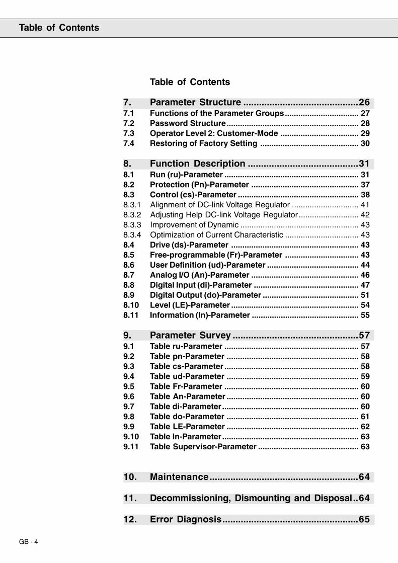
GB - 4
Table of Contents
Table of Contents
7. Parameter Structure ............................................267.1 Functions of the Parameter Groups................................. 277.2 Password Structure........................................................... 287.3 Operator Level 2: Customer-Mode ................................... 297.4 Restoring of Factory Setting ............................................ 30
8. Function Description ..........................................318.1 Run (ru)-Parameter ............................................................ 318.2 Protection (Pn)-Parameter ................................................ 378.3 Control (cs)-Parameter ...................................................... 388.3.1 Alignment of DC-link Voltage Regulator .............................. 418.3.2 Adjusting Help DC-link Voltage Regulator........................... 428.3.3 Improvement of Dynamic ..................................................... 438.3.4 Optimization of Current Characteristic ................................. 438.4 Drive (ds)-Parameter ......................................................... 438.5 Free-programmable (Fr)-Parameter ................................. 438.6 User Definition (ud)-Parameter ......................................... 448.7 Analog I/O (An)-Parameter ................................................ 468.8 Digital Input (di)-Parameter ............................................... 478.9 Digital Output (do)-Parameter ........................................... 518.10 Level (LE)-Parameter ......................................................... 548.11 Information (In)-Parameter ................................................ 55
9. Parameter Survey ................................................579.1 Table ru-Parameter ............................................................ 579.2 Table pn-Parameter ........................................................... 589.3 Table cs-Parameter ............................................................ 589.4 Table ud-Parameter ........................................................... 599.5 Table Fr-Parameter ............................................................ 609.6 Table An-Parameter ........................................................... 609.7 Table di-Parameter............................................................. 609.8 Table do-Parameter ........................................................... 619.9 Table LE-Parameter ........................................................... 629.10 Table In-Parameter............................................................. 639.11 Table Supervisor-Parameter ............................................. 63
10. Maintenance.........................................................64
11. Decommissioning, Dismounting and Disposal..64
12. Error Diagnosis....................................................65
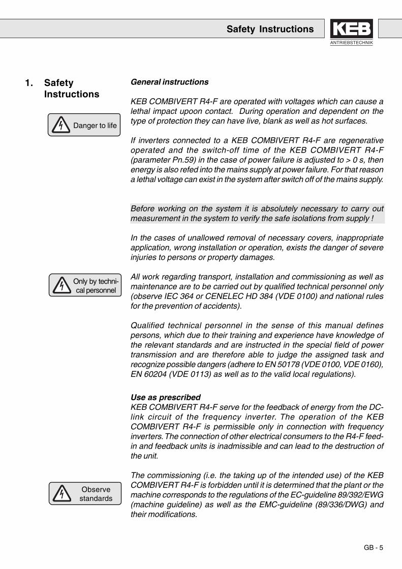
ANTRIEBSTECHNIK
GB - 5
Safety Instructions
Danger to life
Only by techni-cal personnel
General instructions
KEB COMBIVERT R4-F are operated with voltages which can cause alethal impact upoon contact. During operation and dependent on thetype of protection they can have live, blank as well as hot surfaces.
If inverters connected to a KEB COMBIVERT R4-F are regenerativeoperated and the switch-off time of the KEB COMBIVERT R4-F(parameter Pn.59) in the case of power failure is adjusted to > 0 s, thenenergy is also refed into the mains supply at power failure. For that reasona lethal voltage can exist in the system after switch off of the mains supply.
Before working on the system it is absolutely necessary to carry outmeasurement in the system to verify the safe isolations from supply !
In the cases of unallowed removal of necessary covers, inappropriateapplication, wrong installation or operation, exists the danger of severeinjuries to persons or property damages.
All work regarding transport, installation and commissioning as well asmaintenance are to be carried out by qualified technical personnel only(observe IEC 364 or CENELEC HD 384 (VDE 0100) and national rulesfor the prevention of accidents).
Qualified technical personnel in the sense of this manual definespersons, which due to their training and experience have knowledge ofthe relevant standards and are instructed in the special field of powertransmission and are therefore able to judge the assigned task andrecognize possible dangers (adhere to EN 50178 (VDE 0100, VDE 0160),EN 60204 (VDE 0113) as well as to the valid local regulations).
Use as prescribedKEB COMBIVERT R4-F serve for the feedback of energy from the DC-link circuit of the frequency inverter. The operation of the KEBCOMBIVERT R4-F is permissible only in connection with frequencyinverters. The connection of other electrical consumers to the R4-F feed-in and feedback units is inadmissible and can lead to the destruction ofthe unit.
The commissioning (i.e. the taking up of the intended use) of the KEBCOMBIVERT R4-F is forbidden until it is determined that the plant or themachine corresponds to the regulations of the EC-guideline 89/392/EWG(machine guideline) as well as the EMC-guideline (89/336/DWG) andtheir modifications.
1. SafetyInstructions
Observestandards

GB - 6
Observecapacitor
discharge time
Voltagesagainst earth
Only fixedconnection
KEB COMBIVERT R4-F meets the demands of the low-voltage guideline73/231/EWG. The harmonized standards of the series EN 50178 (VDE0160) in connection with EN 60439-1 (VDE 0660 Part 500) and EN 60146(VDE 0558) are applied.
Transport and storageKEB COMBIVERT R4-F is to be protected against inadmissible stress.In particular components may not be bent and/or isolation distances bechanged during transport and handling.
The units contain electro-statically endangered components which canbe destroyed by improper handling. Therefore the contact of electroniccomponents and contacts must be avoided. In the case of mechanicaldefects on electrical and electronic components the unit may not be takeninto operation, since the adherence to applied standards is no longerwarranted.
InstallationAt the installation it is absolutely necessary to observe sufficient minimumdistances as well as sufficient cooling. Climatic conditions according toEN 50178 (VDE 0160) are to be kept.
Electrical connectionBefore carrying out any installation and connecting work the plant is tobe swiched off circuit and protected accordingly.
After the safety isolation of the KEB COMBIVERT R4-F the DC-linkcapacitors are charged with high voltage for a short period. For thatreason any work on the unit may be started only 5 minutes after poweroff.
The connection of the KEB COMBIVERT R4-F is admissible only tosymmetrical networks with a conductor voltage phase (L1, L2, L3) againstN/PE of max. 290 V.
KEB COMBIVERT R4-F is intended only for a fixed connection, sinceespecially with the use of filters discharge currents > 3.5 mA occur. Aprotective conductor cross section of at least 10 mm2 copper or the layingof a second conductor electrically parallel to the protective conductorover separate terminals is prescribed. Generally ground star-shaped withshortest possible connection to main earth (avoid earth loops).
Safety Instructions
Protect againstcontact

ANTRIEBSTECHNIK
GB - 7
Safety Instructions
Avoidinterferences
Isolationmeasurements
Potentialdifferences
During an isolation measurement according to EN 60204 (VDE 0113)the unit must be completely disconnected because of the destructivedanger to the power semiconductors. This is admissible according tostandard, since all units in the context of the final inspection at KEBundergo a high-voltage test as described in EN 50178 (VDE 0160).
When using components that do not employ potential-isolated in-/outputs,it is necessary that a potential equality exists between the componentsto be connected (e.g. through equalizing line). In the case of disregard itcan lead to the destruction of the components through equalizing currents.
A trouble-free and safe operation of a KEB COMBIVERT R4-F is to beexpected only when following connection instructions are observed. Inthe case of deviations from these specifications malfunctions anddamages can occur in indivdual cases.• Observe system voltage!• Lay power and control cables separately (> 15 cm)!• Use shielded/twisted control cables. Apply shield to one side of the
KEB COMBIVERT R4-F on PE!• For the controlling of the logical inputs use only suitable switching
devices whose contacts are suited for extra-low voltages!• Ground the housing of the KEB COMBIVERT R4-F well. Apply shields
of power cables on both sides over a large area (remove laquer)!• Ground the control cabinet or the plant star-point wise to the main
earth (absolutely avoid earth loops!).
If protection of individuals is required at the installation of systemsprotection, the feed-in and feedback units must be secured in accordancewith EN 50178 (VDE 0160) as follows:
• 3-phase units through RCMA’s with separator (preferred use) or RCD’sType B (all-current sensitive FI’s).
The tripping current of the RCD’s should be 300 mA or higher in order toprevent a premature tripping through leakage currents of the inverter(approx. 200 mA).
Dependent on the load, the motor cable length and the use of radiointerference suppression filters substantially higher leakage currents canoccur.
The connection instructions of the respective manufacturer as well asthe valid local rules are to be observed at the connection.
RCD(earth-leakagecircuit breaker)

GB - 8
Depending on the existing system configuration (TN, IT, TT) furtherprotective measures according to VDE 0100 Part 410 (Part 4, Chap. 41)are necessary.
For TN-systems it is e.g. the protection though overcurrent devices, at IT-systems the isolation monitoring with pulse-code measuring procedure.For all system configurations a protective separation can be used if thenecessary power and line length permit this.
Operating instructionsBefore start-up reattach all appropriate covers and check the terminalsand screws for tight fit.
KEB COMBIVERT R4-F, dependent on the type, can be adjusted in sucha way that they restart again automatically after a malfunction (e.g.undervoltage error). Therefore plants must be, if necessary, equippedwith additional monitoring and procective devices (in accordance withthe law on technical working materials, rules for the prevention ofaccidents etc.) .
The KEB COMBIVERT R4-F are conditionally short-circuit proof (EN50178 (VDE 0160)). After resetting the internal protective devices theintended function is ensured. Exception:
• If ground faults or short-circuits occur repeatedly at the output it canlead to a defect in the unit.
• If a short-circuit occurs during the regenerative operation it can leadto a defect in the unit.
The increased DC-link voltage of approx. 680 V (instead of 540V at 400V-systems) can lead with motors connected in series to premature aging ofthe insulation system. Only motors with appropriate high voltageendurance should be used.
Automaticrestart
Conditionallyshort-circuit proof
Safety Instructions
Motor insulationresistance

ANTRIEBSTECHNIK
GB - 9
Product Description
2. ProductDescription
The KEB COMBIVERT R4-F (sinusoidal feed-in and feedback unit) issuitable in combination with frequency inverters, which can be operatedon a DC-Bus connection of 420...800 V and possess a re-charge shunt.
It is to be used where system reactions through non-sinusoidal voltageinput shall or must be avoided. For regenerative operating cases, whereup to now a braking module transformed the surplus energy in unusedheat, the KEB COMBIVERT R4-F represents an economical solution.
The multi-variable control has the function to adjust a power factor of λ =+/- 1, i.e. only active power is taken from or fed back to the supply system.The DC-link voltage (UZK) is regulated onto a constant value. Due tothe increased DC-link voltage (e.g. Uzk_set = 680 V) a larger armatureoperating range respectively a shifting of the field weakening range tohigher frequencies can be adjusted with standard motors. Thus moreoverload reserves than with feed-in over uncontrolled rectifier bridgesare available.
2.1 Use
Energy balance, here formotoric operation
R4 - F FU
Reactive power
Active powerInductivity
Motor impedance
therm. losses therm. losses therm. losses therm. losses
Uzk = const.u , i
t
t
Uzk
Uzk_set
Uzk_real
u
i
Direction of energy e.g. motoric
Sou
rce
volta
ge
Mai
ns v
olta
ge
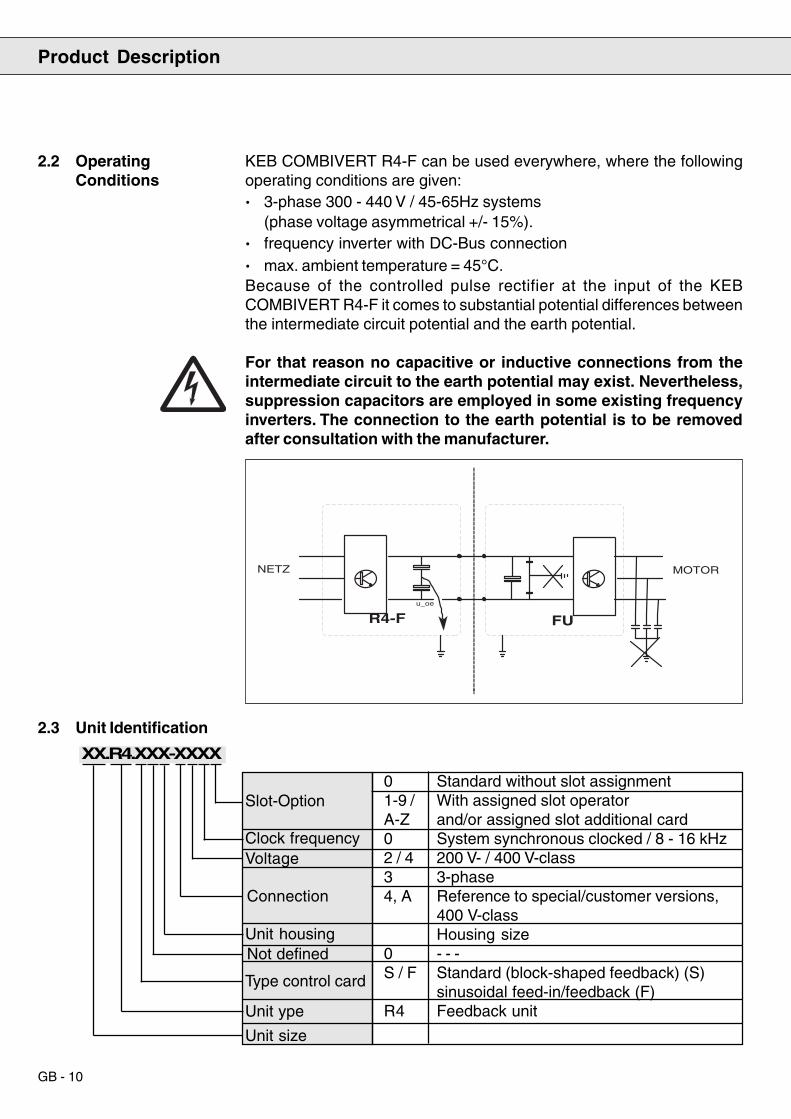
GB - 10
R4-F FU
NETZ MOTOR
u_oe
KEB COMBIVERT R4-F can be used everywhere, where the followingoperating conditions are given:· 3-phase 300 - 440 V / 45-65Hz systems
(phase voltage asymmetrical +/- 15%).· frequency inverter with DC-Bus connection· max. ambient temperature = 45°C.Because of the controlled pulse rectifier at the input of the KEBCOMBIVERT R4-F it comes to substantial potential differences betweenthe intermediate circuit potential and the earth potential.
For that reason no capacitive or inductive connections from theintermediate circuit to the earth potential may exist. Nevertheless,suppression capacitors are employed in some existing frequencyinverters. The connection to the earth potential is to be removedafter consultation with the manufacturer.
2.2 OperatingConditions
Product Description
2.3 Unit Identification
XX.R4.XXX-XXXX
Slot-Option
Type control card
Not definedUnit housing
Connection
VoltageClock frequency
Unit ype
Unit size
0 Standard without slot assignment1-9 / With assigned slot operatorA-Z and/or assigned slot additional card0 System synchronous clocked / 8 - 16 kHz2 / 4 200 V- / 400 V-class3 3-phase4, A Reference to special/customer versions,
400 V-classHousing size
0 - - -S / F Standard (block-shaped feedback) (S)
sinusoidal feed-in/feedback (F)R4 Feedback unit
ANTRIEBSTECHNIK
GB - 11
Danger to life
Only by techni-cal personnel
Observestandards
The storage of the KEB COMBIVERT R4-F has to take place in its origi-nal packaging. It must be protected against moisture and excessivecooling and thermal effect.
The transport over large distances has to take place in the originalpackaging. It must be secured against impacts and shocks.
Observe the labelling on the covering box!
After removing the covering box the KEB COMBIVERT R4-F is to besecurely placed on stable base.
The installation and commissioning of the KEB COMBIVERT R4-F ispermissble only through qualified technical personnel. A safe and trouble-free operation is ensured by the compliance with the valid regulationsaccording to DIN VDE 0100, DIN VDE 0113, DIN VDE 0160, DIN VDE0875 as well as the relevant local regulations. The unit is to be groundedover the protective conductor. The power connections L1_2, L2_2 andL3_2 as well as the connections for the synchronization (L1, L2, L3) areto be effected with shielded cables.
Attention, the terminals L1, L2, L3, as well as -IN, -OUT, +OUT, +IN andL1_2, L2_2, L3_2 carry dangerously high voltages in switched-on status!
All installation and connection work is to be done only in off-circuitcondition!
The DC-link capacitors of the KEB COMBIVERT R4-F are still chargedwith high voltage for some minutes after switch off. Therefore work onthe unit may be carried out only 5 minutes after power off!
3. Storage andTransport
4. Installation
Installation

GB - 12
4. Installation
Installation
4.1 Unit Installation
4.1.1 Dimensions
C
B B2H
ØF
GA
ØFB
H GC A
KEB COMBIVERT R4-FHousing size A B C F G H Weight
G 170 340 255 7 150 330 10 kgR 340 520 355 10 300 495 25-29 kg
T
AN
TR
IEB
ST
EC
HN
IK
HF
-FIL
TE
R14.F
4.T
60-1
008
LIN
E
INV
ER
TE
R
Kar
l E. B
rinkm
ann
Gm
bHD
-326
77 B
arnt
rup
3x50
0V+1
0% A
C/5
0-60
Hz
20A
@ T
-45
°CH
PF:
-25
°C -
+85
°C
E 1
6754
4LI
ST
ED
IND
CO
NT
EO
5D12
LLLUUU
LLLUUU
L1'
L2'
L3'
PE
L1'
L2'
L3'
PE
U
DA
H
B
F S
S1
V
LE1
E
H
H
C
K
F
Radio interference suppression filterType A B C D E F H Weight
16.E4.T60-1001 181 415 56 150 330 400 7 3,2 kg19.E4.T60-1001 300 445 66 250 330 420 7 6,1 kg
Commutating reactorType A B C F G H Weight
16.DR.R08-2351 15 237 230 8 123 152 17 kg21.DR.R08-8541 21 337 300 11 162 200 45 kg

ANTRIEBSTECHNIK
GB - 13
4.1.2 EnvironmentalConditions
4.1.3 InstallationInstructions
· Install and ground KEB COMBIVERT R4-F stationary.· At the placing observe the minimum distances to surrounding elements
(see installation instructions).· Prevent the penetration of dust into the KEB COMBIVERT R4-F. For
the installation into a dust-proof housing sufficient heat dissipationmust be ensured.
· KEB COMBIVERT R4-F is to be protected against aggressive gasesand fluids.
· Consumers that produce electrical or magnetic fields or exertinfluences on the voltage supply, are to be placed as far away aspossible and measurements for the suppression of interferences mustbe taken.
The KEB COMBIVERT R4-F isintended for the ver ticalinstallation into the controlcabinet. A minimum distance of15 cm at the air inlet and outletopenings to the neighbouringmodules is to be kept.Feedback units are mountableone above the other withoutkeeping a minimum distance.The same applies for the side byside mounting of feedback unitswith frequency inverters.
Site altitude max. 2000 m. At installation above 1000 m a power reductionof 1 % per 100m must be taken into consideration, i.e. 1500 m above sealevel = 95% Prated.
Max. permissible limit values KEB COMBIVERT R4-FAmbient temperature in operation -10°C . . . +45°CStorage temperature -25°C . . . +70°CTransport temperature -25°C . . . +70°CRelative humidity max. 95% no condensation
(code letter *F* DIN 40040)
15 cm
15 cm
3 cm
Installation

GB - 14
4.1.4 Directions for EMC-conform Wiring
Installation
• Set up the control cabinet or plant proper and according to function
• In order to avoid interference coupling :
a) power/supply cables,b) motor cables of frequency inverter/servo controller,c) control and data lines (low-volt level < 48 V),
are to be installed with a minimum distance of 15 cm.
• To obtain low-resistance HF-connections, earthing and shielding aswell as other metallic connections (e.g. mounting plate, installeddevices) must be applied over a large area on a metallically brightbase. Use earthing and potential equalization lines with the largestpossible cross section (at least 10 mm²) or thick earthing strips.
• If external radio interference suppression filters are used, they are tobe placed with a distance of max. 30 cm to the interference sourceand installed with very good, area covering contact to the mountingsurface.
• Always provide inductive switching devices (contactors, relays etc.)with suppression elements such as varistors, RC-elements orprotective diodes.
• Keep all connections as short as possible and close to the referencepotential, since freely pending lines work just like antennas.
• Avoid back-up loops on all connecting cables. Apply unoccupied litzwires to both sides of the protective conductor.
• With unshielded lines lead wires and return lines must be twisted todampen symmetrical interferences.
On the following pages you find examples for set-up and wiringof an EMC-conform control cabinet.

ANTRIEBSTECHNIK
GB - 15
3
4
10
9
13
1
2
9a
13a
5 7
8
6
14
15 cm
15 cm
Installation schematic - EMC-conform control cabinet setup
1 Mains fuse
2 Main contactor
3 Radio interference suppression filter
4 Commutating reactor
5 R4-feed-in and feedback unit
6 Intermediate circuit fuse
7 Frequency inverter
8 Motor feed cable
9 Mounting plate is common neutral point (PE)
9a Neutral point (PE) for control range
10 Equipotential bonding with the housing earth
13 Supply connection
13a Supply connection, control range
14 Control lines, housing is tied into over a large area
The above installation schematic represents the optimal solutionin the arrangement of the units. If the dimensions of the controlcabinet permit it, this schematic should be realized.
Control range Power range
Installation

GB - 16
4.2 Connection PowerCircuit
Terminal FunctionL1, L2, L3 SynchronizationOH, OH Connection for temperature sensor for
for commutating reactor-IN, +IN Input terminals for +/- DC-intermediate circuit-OUT, +OUT In-/output terminals for +/- DC-intermediate circuitL1_2, L2_2, L3_2 3-phase supply connection
On the line-side and in the DC-intermediate circuit the unit must beprotected with fuses of operating class gR. In order to avoid inadmissiblehigh commutation notches a commutating reactor must be connected online side. The connection of the synchronization line is carried out overpre-fusing max. 4 A (according to VDE line protection) with twisted cables0.75 mm2.
4.2.1 TemperatureMonitoringCommutatingReactor
4.2.2 StandardConnection
Several frequency inverters can be connected to the DC-Bus. Payattention to the total connected load.
L1 L2 L3OH OH
- IN - OUT + OUT + IN L1 _2 L2 _2 L3 _2
Bridge, if no monitoringtakes place
Thermo-contact(NC contact)
Temperature sensor (PTC)Response resistor > 4 kΩResetting resistor < 750 Ω(according to VDE 0664)
Installation
R4-IN -OUT +OUT +IN
L1_2 L2_2 L3_2 PE
DC-FU+UZK -UZK U V W
PE
DC-FU+UZK -UZK U V W
PE
M3~
M3~
L1 L2 L3
PE
L1L2L3
Filter
3
L1L2L3
L1L2L3
L3'L3'L2'L2'L1'L1'

ANTRIEBSTECHNIK
GB - 17
4.3 Technical Data
*) The absorbed apparent power is a function of the mains voltage (S f Unetz netz= ( ) )
S U Inetz netz n= ⋅ ⋅3 , as the power factor is λ = +/- 1: P Snetz netz=
Installation
Unit nomination KEB COMBVERT R4 14.R4.F 16.R4.F0G-3440 21.R4.F0R-3440
Unit design Die-cast heat sink/
Plastic top
(G-housing)
Unit dimensions ( H · B · T in mm) 520 · 340 · 355
Input fuse external in 160 A
control cabinet
D.C.-link fuse external in 250 A
control cabinet
Supply power circuit DC-supply from 260 . . . 400 VD.C.-link-FI
Maximum leakage current max.< [mA] 50
Type of protection IP 20
Line reactor - external 100% ED 21.DR.R08-8541
Ln = 0,85 mH
Mains filter - external 19.E4.T60-1001
In = 90 A
Symbol 14.R4.F0G-3241 16.R4.F0G-3440 20.R4.F0G-3440
System voltage class Umains 180 . . . 220 VSystem frequency fmains
Number of system phases
Rated voltage Un 200 VRated apparent power Sn 11 kVA 23 kVA 52 kVA
Rated D.C.-link voltage Uzk_n 340 VRated D.C.-link current Izk_n 76 A
*Max. incoming/energy recovery rating 1.5 Smains_max 18,8 kVA 37,5 kVA 78 kVA
(Un= 400 V overload operation)
Rated current per line In 75 A
(100% cyclic duration factor)
Short-time max. overcurrent IMAX 135 A
(eff. line current [max. 30 sec.]
Peak current - OC (line current) IOC 162 A
Supply voltage digital inputs Udig
int. supply voltage Uout
(terminals 24VOUT)
ext. supply voltage Uin
(terminal 24VIN)
Line cross section supply connection 50 mm2
Line cross section D.C.-link 70 mm2
Line crosss section sychronization
50...60 Hz ± 5Hz
400 V
0,75 mm2
3
24 V (-10%, +25%)
13 . . . 30 V
18 V
93,3 A
10 mm2
16 mm2
340 · 170 · 255
63 A
(Operating class gR)
100 A
(Operating class gR)
420 . . . 800 V DC
17
16.DR.R08-2351
Ln = 2,20 mH
16.E4.T60-1001
In = 33 A
300...440V
680 V
33,5 A
33 A
49,5 A
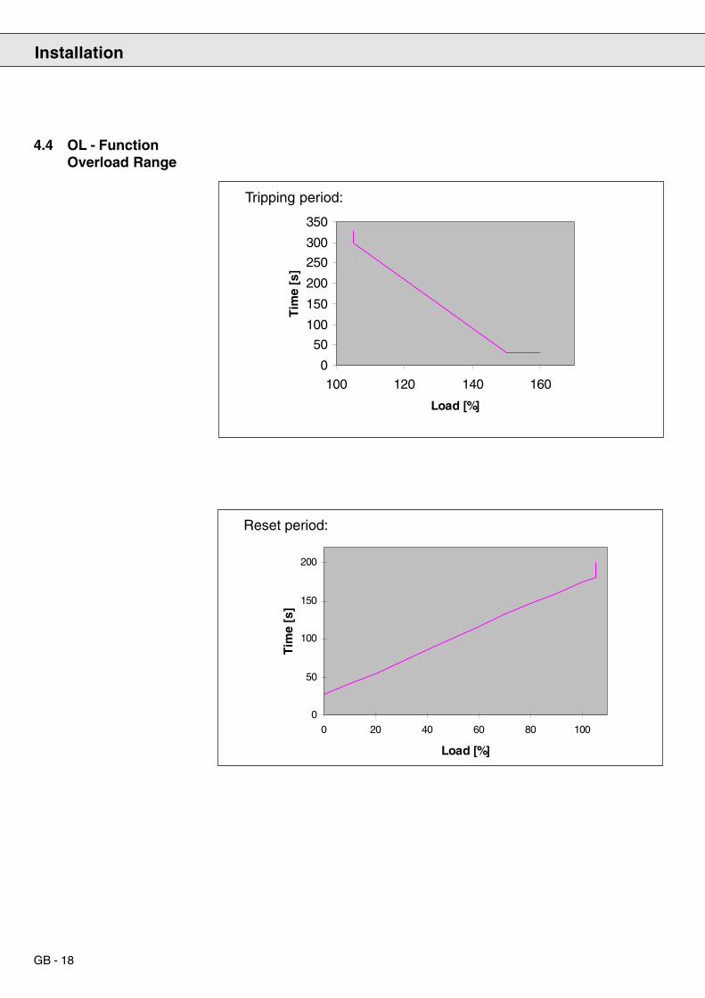
GB - 18
0
50
100
150
200
0 20 40 60 80 100
Load [%]
Tim
e [s
]
4.4 OL - FunctionOverload Range
0
50
100
150
200
250
300
350
100 120 140 160
Load [%]
Tim
e [s
]
Tripping period:
Reset period:
Installation

ANTRIEBSTECHNIK
GB - 19
5. Control TerminalStrip X2
1 2 3 4 5 6 7 8 9 10 11 12 13 14 15 16 17 18 19 20 21 22 23
Installation
Terminal Name Specification DescriptionX2.1 RLA1 Continuous limit current= 6A;400V~/300V- RA1 / RC1 NO-contactX2.2 RLB1 Switching capacity~ 1500 VA RB1 / RC1 NC-contactX2.3 RLC1X2.4 freeX2.5 I1 Noise immunity: 2kV Programmable input
logical 1: +/- (12..30V)Logic: NPN/PNP
intern. input resistance: ca. 2kΩX2.6 Uout +18V(+/- 20%); max 20mA +18V output
At connection of external voltageis Uout ~ ext.voltage( X2.18)
X2.7 EXTGND Ground for Uout and dig. I/OX2.8 ST see terminal X2.5 Control releaseX2.9 Uout see terminal X2.6
X2.10 EXTGND see terminal X2.7X2.11 RST see terminal X2.5 ResetX2.12 Uout see terminal X2.6X2.13 EXTGND see terminal X2.7X2.14 OUT1 programmable PNP-transistor Digital output
output, ca. 16V(+/- 20%) / max.20mA at external supply ca.
(Uout - 3V) +/-20%/ max. 20mAX2.15 ANOUT Voltage range: +/- 10 V Analog output
Internal resistance: 100 ΩResolution: 12 Bit
X2.16 GND Ground for ANOUTX2.17 freeX2.18 24V IN External voltage supply (+24..30V) for ext. voltage supply
the I/O´s. If external components shallbe supplied from Uout with current
input > 110mA an external supply mustbe made available at terminal X2.18.
Reference potential: EXTGND (Kl.19)X2.19 EXTGND see terminal X2.7X2.20 freeX2.21 RLA2 RA2 / RC2 NO-contactX2.22 RLB2 see terminal X2.1-X2.3 RB2 / RC2 NC-contactX2.23 RLC2

GB - 20
In order to avoid malfunctioning by interference voltage feed-in at thecontrol inputs, following instructions should be considered:
· Use shielded/twisted cables.
· Attach shield on one side of the inverter to earth potential.
· Lay control and power cables separately (ca. 10...20 cm distance).
· Lay lines in right angle.
· Electrical isolation between terminals for in-/outputs and the analogoutput (i.e. do not connect EXTGND with GND).
5.1 Connection ofControl Terminals
1 2 3 4 5 6 7 8 9 10 11 12 13 14 15 16 17 18 19 20 21 22 23
1 2 3 4 5 6 7 8 9 10 11 12 13
+
14 15 16 17 18 19 20 21 22 23
1 2 3 4 5 6 7 8 9 10 11 12 13
+
14 15 16 17 18 19 20 21 22 23
Analog outputDigital tansistor output
Internal voltage supply
External voltage supply of digital inputs
Digital / analog outputs
Installation

ANTRIEBSTECHNIK
GB - 21
6. Operation of theUnit
Operation of the Unit
6.1 Initialization
Basically two possibilities of operating the KEB COMBIVERT R4-F areavailable:
1. Operation by means of Interface-Operator
2. Operation by means of personal computer and the system softwareKEB COMBIVIS
6.2 Control duringOperation
After connecting the supply voltage the KEB COMBIVERT R4-F isinitialized. First the power circuit identification is checked. When identifyingan invalid power circuit then the error ”E.PUC” (Power Unit Check) istriggered and shown in the display of the operator. The error cannot bereset, the power circuit must be checked.When identifying a valid power circuit, the KEB COMBIVERT R4-Fchanges into status „Syn“. During this synchronization phase followingprocesses run.
1. The line frequency is determined. If it is not within the tolerance of 45- 65 Hz, the unit remains in the operating condition „Syn“.
2. The rotary field is determined.
3. Check of phase assignment of synchronous signals to the systemphases at the power circuit. If one phase is missing or in case of awrong phase assignment the error ”E.Syn” is triggered. The errorcannot be reset. The connections must be checked and the feedbackunit must be switched on again.
After successful synchronization the correct connection of the KEBCOMBIVERT R4-F is ensured. If the release signal (terminal ST) is set,the KEB COMBIVERT R4-F automatically starts its function.

GB - 22
6.2.1 Operation with Inter-face Operator
Interface-Operator (Part no. 00.F4.010-1009)
5-digit LED-Display
RS232/485-Interface
Functional Keys
Operation-/Error Display(left LED not occupied)
FUNC.
SPEED
START
STOP
ENTER
F/R
5 4 3 2 1
9 8 7 6
Isolated RS232/485-InterfacePin RS485 Signal Meaning1 - - reserved2 - TxD transmit signal/RS2323 - RxD receive signal/RS2324 A’ RxD-A receive signalA/RS4855 B’ RxD-B receive signalB/RS4856 - VP supply voltage
+5V (Imax = 10mA)7 C/C’ DGND data reference potential8 A TxD-A transmit signal A/RS4859 B TxD-B transmit signalB/RS485
Operation of the Unit
An operator is needed for the local operation of the KEB COMBIVERTR4-F, which is attached on the front side of the unit. To avoid malfunctionsthe inverter must be in status „nOP“ (control release X1.8 open) whenattaching/pulling off the operator. When starting the KEB COMBIVERTR4-F without operator, the start up is done with the values stored last orwith the factory setting. The LED-display of the operator indicates alloperating conditions of the KEB COMBIVERT R4-F. By way of four keysoperating parameters can be called or adjustments to different applicationconditions can be carried out. The password input is also possible.
Additionally the operator has a 9-pole RS232/485 interface, which servesfor the communication with a data transfer device.
Local Operation
BUS- Operation

ANTRIEBSTECHNIK
GB - 23
Operation of the Unit
6.2.2 Operation with PCand System SoftareKEB COMBIVIS
Instructions concerning the installation and operation of the systemsoftware KEB COMBIVIS are found in the corresponding softwaredescription.
Regarding the operation over keyboard it is differentiated between twobasic operating modes:
Mode 1 Representing and changing of parameter identification(number and group)
Mode 2 Representing and changing the parameter values
Changing between these modes is done by pressing the FUNCT-key.Pressing the FUNCT-key in mode 2 shows the value of the adjustedparameter. On pressing the key again the parameter identification isdisplayed.
The individual specifications for the identification of the parameters areseparated by points. One of these points flashes, thus showing thespecification that can be modified with UP/DOWN. By pressing ENTERthe flashing point can be moved to the left. If ENTER is pressed when thepoint of the parameter group flashes then the point of the parameternumber flashes.
To select another parameter group, press ENTER repeatedly until thepoint is behind the parameter group flashes. Now the desired parametergroup can be adjusted with UP/DOWN. When changing the parametergroup the parameter number is set to the lowest available number in thenew group.
To change the parameter number, the flashing point must first be broughtbehind the display of the parameter number, afterwards the parameternumber can be changed with UP/DOWN. If the highest parameter of agroup is reached and UP pressed, the lowest parameter number of thisgroup appears. When reaching the lowest parameter number and pressingDOWN appears the highest parameter number of this group. A change ofthe parameter number does not change the parameter group.
6.3.1 Standard Operation
6.3.2 Mode 1, Display ofParameterIdentification
Changing theParameter Group
Changing theParameter Number
6.3 Keyboard Operation

GB - 24
FUNC.
SPEED
ENTER
F/R
START START
START START
FUNC.
SPEED
STOP STOP
STOP STOP
Parameter number Parameter group
Mode 1Parameteridentification
Mode 2Parameter value
Option betweenparameter numberand parameter group
Changingthe parameter number,the parameter group
Option betweenoperating mode 1 andoperating mode 2
Changing the parametervalue
In the parameter value display the value of adjusted parameters can bechanged by pressing the keys UP or DOWN. The modifications areimmediately effective and nonvolatile stored, i.e. they are still valid evenafter switching off the unit. It is not necesary to acknowledge the inputwith ENTER.
For some parameters it is not sensible for the value adjusted with UP/DOWN to become valid immediately. These parameter are called Enter-Parameter, as the input must be confirmed with ENTER. Pressing UP/DOWN only changes the display, but not the value stored in the feedbackunit. If the displayed value is different to the stored value, it is marked bya point in the display. By pressing the ENTER-key the display value isstored in the KEB COMBIVERT R4-F and the point goes out. Theparameter value display of an Enter-Parameter alays starts with the valuestored in the KEB COMBIVERT R4-F.
Enter Parameter
6.3.3 Mode 2, Changing ofParameter Values
Operation of the Unit

ANTRIEBSTECHNIK
GB - 25
ENTER
F/R
Error Acknowledge message with ENTER
In case a failure occurs in the KEB COMBIVERT R4-F, the display isoverwritten with an error message. This error message is representedflashing.
By pressing ENTER the display of the error message is terminated andthe display shows the parameter value of the last adjusted parameter.
Acknowledging the error message with ENTER is not an error reset, i.e.the error status in the KEB COMBIVERT R4-F is not reset. Thus it ispossible to correct the adjustments before the error reset. An error resetis only possible by the terminals control release or reset.
Some inputs are acknowledged by the KEB COMBIVERT R4-F with acheckback signal. Possible checkbacks are:
• „PASS“ Factory setting was loaded
• „nco“ Factory setting could not be loaded
These checkback signals must be acknowlegded with ENTER.
6.4 Special Displays
Error message
Checkback signal
Operation of the Unit

GB - 26
Each parameter is clearly described by three specifications.
1. Parameter number
2. Parameter group
3. Parameter set (only at programmable parameters)
The individual parameters of a group are differentiated by the number.Several parameters are functional-related combined in one parametergroup. That means, all parameters, that are needed for the adjustment ofone function, are in one parameter group. The KEB COMBIVERT R4-Fhas following parameter groups:
7. ParameterStructure
Run(ru) - Parameter
Protection(Pn) - Parameter
(dS) - Parameter
Control(CS) - Parameter
User-definition(ud) - Parameter
Free-prog.(Fr) - Parameter
Analog-I/O(An) - Parameter
Digital-In(di) - Parameter
Digital-Out(do) - Parameter
Level(LE) - Parameter
Information(In) - Parameter
Contains all status displays, i.e. all values thatchanged during operation, without havingchanged the parameter
All protective functions and Keep-on-runnigfunctions (e.g. Auto Restart)
Switching frequency
Control parameter for D.C.-link circuit and currentcontrol
All parameters for the individual adjustment of theoperator panel and serial interface
Parameters for the programming and activationof parameter sets
Programming of the analog output
Programming of digital inputs
Programming of digital outputs
Swtiching conditons for digital outputs
Informationen about type of inverter, serialnumber and diagnosis parameters like errorcounter, QS-number etc.
Operation of the Unit

ANTRIEBSTECHNIK
GB - 27
7.1 Functions of theParameter Groups
ru-Parameter
Operatingdisplays
In-Parameter
Invertercharacteristics
Fr-Parameter
Parameter setprogramming
ud-Parameter
Businterface and
operatorhandling
CP-Parameter
Final customerparameters
Terminal Strip
An-Parameter
Analog Inputsand Outputs
di-Parameter
Digital Inputs
do-Parameter
Digital Outputs
LE-Parameter
Switching level
Operation of the Unit
ds-Parameter
Modulator
CS-Parameter
Control parameterProtective and
Keep on runningfunctions
Pn-Parameter
Main
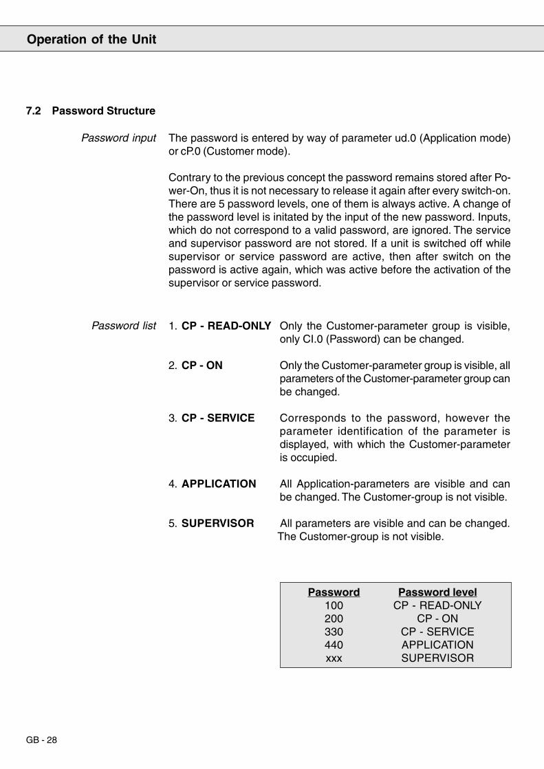
GB - 28
7.2 Password Structure
Password input
Password list
The password is entered by way of parameter ud.0 (Application mode)or cP.0 (Customer mode).
Contrary to the previous concept the password remains stored after Po-wer-On, thus it is not necessary to release it again after every switch-on.There are 5 password levels, one of them is always active. A change ofthe password level is initated by the input of the new password. Inputs,which do not correspond to a valid password, are ignored. The serviceand supervisor password are not stored. If a unit is switched off whilesupervisor or service password are active, then after switch on thepassword is active again, which was active before the activation of thesupervisor or service password.
1. CP - READ-ONLY Only the Customer-parameter group is visible,only CI.0 (Password) can be changed.
2. CP - ON Only the Customer-parameter group is visible, allparameters of the Customer-parameter group canbe changed.
3. CP - SERVICE Corresponds to the password, however theparameter identification of the parameter isdisplayed, with which the Customer-parameteris occupied.
4. APPLICATION All Application-parameters are visible and canbe changed. The Customer-group is not visible.
5. SUPERVISOR All parameters are visible and can be changed.The Customer-group is not visible.
Password Password level100 CP - READ-ONLY200 CP - ON330 CP - SERVICE440 APPLICATIONxxx SUPERVISOR
Operation of the Unit

ANTRIEBSTECHNIK
GB - 29
7.3 Operator Level 2:Customer-Mode
The parameters in the CP-parameter group can be specified by the user.Only CP.0 has a fixed assignment. It always contains the password input.
Which parameters are represented by the individual CP-parameters, isdefined in the appropriate parameters of the ud-group (USER DEFINITI-ON) (see page 44).
With the respective ud-parameter the address for the CP-parameters 1 -24 can be determined. Restrictions and procedure are described in thechapter „Function description ud-parameters“. In the CP-group onechanges between the parameters with UP/DOWN. A change of the groupor the set is not possible. With FUNC it is being switched between theparameter value display and the parameter identification.
To change from the operator control level 2 (application mode) to theoperator control level 1 (customer-mode) or vice versa you must enterthe respective passwords.
The adjusted value is not immediately accepted in the ENTERparameters. When this type of parameter is changed a point appearsbehind the last digit. By pressing ENTER the adjusted value is acceptedand non-volatile stored.
Use the function key toswitch between theparameter value and theparameter number.
With UP/START and DOWN/STOP theparameter number is increased/decreased.
With UP/START andDOWN/STOP the valueof parameters which canbe changed isincreased/decreased.
STOP
START
STOP
START
FUNC.
SPEED
•••
FUNC.
SPEED
ENTER
F/R
Operation of the Unit

GB - 30
Display Parameter Parameter Factory setting
in Application Mode Description
CP. 0 Password input customer on
CP. 1 Inverter status ru. 00
CP. 2 Uzk_actual ru. 11 ---
CP. 3 Uzk_max ru. 12 ---
CP. 4 Uzk_set ru. 48 ---
CP. 5 Uzk_set source cs. 37 uzk_set constant
CP. 6 Uzk_set constant cs. 28 680 V
CP. 7 kv UZK_set cs. 24 1,2
CP. 8 kp Uzk-controller cs. 25 2000
CP. 9 ki Uzk-controller cs. 26 80
CP. 10 kp I_uvw cs. 33 50000
CP. 11 kv UZK_izk cs. 30 50
CP. 12 Apparent current ru. 09 ---
CP. 13 Load ru. 07 ---
CP. 14 max. apparent current ru. 29 ---
CP. 15 Function analog Out An. 14 Apparent current
CP. 16 Amplification analog Out An. 15 1
CP. 17 Input function di. 03 disable
CP. 18 Condition 1 do. 01 enable
CP. 19 Condition 2 do. 02 ready
CP. 20 Output function 1 do. 09 do 1
CP. 21 Output function 2 do. 10 do 2
CP. 22 Load level 1 LE. 08 0
CP. 23 Apparent current level 1 LE. 12 0
CP. 24 DC-link voltage level 1 LE. 24 0
7.4 Restoring ofFactory Setting
Operation of the Unit
The factory setting can be restored any time. For that the following valuesmust be adjusted via the keyboard of the operator. The inverter must bein operating status ”nop” (no control release).
CP.0 = 440 Fr.0 = - 2 ud.0 = 200

ANTRIEBSTECHNIK
GB - 31
The run(ru)-parameter group combines all parameters that display thecurrent operating status of the inverter. The parameters of this group areread-only. An exception form the peak value memories ru.8, ru.12 andru.29, which are deleted by the input of any value.
8. FunctionDescription
8.1 Run (ru)-Parameter
General
Parameter Summary
Run (ru)-Parameter
ru.0 Inverter statusru.7 Actual loadru.8 Peak loadru.9 Apparent currentru.10 Active currentru.11 DC-bus voltageru.12 DC-bus voltage / peak valueru.14 Input terminal statusru.15 Output terminal statusru.16 Internal input statusru.17 Internal output statusru.24 Display OL-counterru.29 Peak currentru.31 Operating-hour counter 1ru.32 Operating-hour counter 2 modulation _onru.48 DC-link setpoint valueru.49 Absorbed electrical energyru.50 Refed electrical energyru.52 Mains frequency
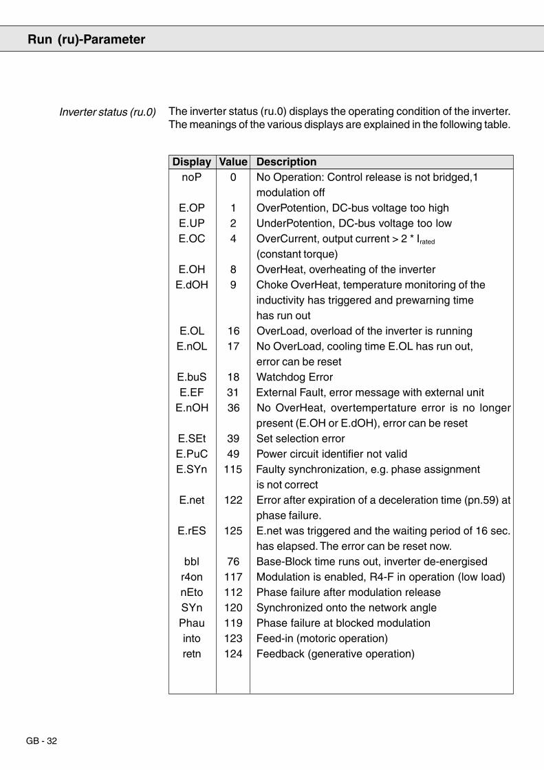
GB - 32
Inverter status (ru.0) The inverter status (ru.0) displays the operating condition of the inverter.The meanings of the various displays are explained in the following table.
Display Value DescriptionnoP 0 No Operation: Control release is not bridged,1
modulation offE.OP 1 OverPotention, DC-bus voltage too highE.UP 2 UnderPotention, DC-bus voltage too lowE.OC 4 OverCurrent, output current > 2 * Irated
(constant torque)E.OH 8 OverHeat, overheating of the inverter
E.dOH 9 Choke OverHeat, temperature monitoring of theinductivity has triggered and prewarning timehas run out
E.OL 16 OverLoad, overload of the inverter is runningE.nOL 17 No OverLoad, cooling time E.OL has run out,
error can be resetE.buS 18 Watchdog ErrorE.EF 31 External Fault, error message with external unit
E.nOH 36 No OverHeat, overtempertature error is no longerpresent (E.OH or E.dOH), error can be reset
E.SEt 39 Set selection errorE.PuC 49 Power circuit identifier not validE.SYn 115 Faulty synchronization, e.g. phase assignment
is not correctE.net 122 Error after expiration of a deceleration time (pn.59) at
phase failure.E.rES 125 E.net was triggered and the waiting period of 16 sec.
has elapsed. The error can be reset now.bbl 76 Base-Block time runs out, inverter de-energised
r4on 117 Modulation is enabled, R4-F in operation (low load)nEto 112 Phase failure after modulation releaseSYn 120 Synchronized onto the network anglePhau 119 Phase failure at blocked modulationinto 123 Feed-in (motoric operation)retn 124 Feedback (generative operation)
Run (ru)-Parameter

ANTRIEBSTECHNIK
GB - 33
Parameter ru.7 shows the actual load of the inverter in %. 100% meansthe output current which corresponds to the rated current of the inverter.Only positive values are displayed, i.e. a differentiation whether theinverter feeds-in or feeds-back is not possible on the basis of ru.7.
ru.8 makes it possible to immediately detect peak loads within anoperating cycle. In addition to it the highest value, that occurs in ru.7, isstored in ru.8. The peak memory can be deleted by pressing the UP orDOWN key, or by Bus by writing any value to the address of ru.8. Thememory is deleted when the inverter is switched off.
In ru.9 the actual apparent current is displayed with a resolution of 0.1 A.The resolution over bus is likewise 0.1 A.
ru.10 displays the actual active current.
Display of the actual DC-bus voltage with a resolution of 1 V. The highestvalue is stored in ru.12. ru.12 can be deleted by pressing the UP or DOWNkey. The peak memory can be deleted by bus by writing any value toru.12.
Actual load (ru. 7)
Peak load (ru.8)
Apparent current (ru.9)
Active current (ru.10)
DC Voltage (ru.11, ru.12)
ru.14 shows the logical status of the input terminals. Logical combinations,strobe or edge-triggering are not taken into consideration.
Input terminal status(ru.14)
Bit - No. Decimal value Input Terminal
0 1 ST (Control release) 8
1 2 RST (Reset) 11
4 16 I1 (Prog. Input 1) 5
If one input is triggered, the corresponding decimal value is displayed. Ifseveral inputs are triggered, the sum of the decimal value is displayed.
Run (ru)-Parameter

GB - 34
Output terminal status(ru.15)
ru.15 permits the control of digital outputs. ru.15 takes into account thelogic operations of the digital outputs (do.0, d0.9 to do.25). For each activeoutput the appropriate decimal value is displayed. If several outputs areactive, then the sum of the decimal values is displayed.
Bit - No. Decimal value Output Terminal
0 1 Out 1 (Transistor output) 12
1 2 Out 2 (RelayRLA,RLB,RLC) 1, 2, 3
2 4 Out 3 (Relay FLA,FLB,FLC) 21, 22, 23
4 16 Out A (Internal output A) none
5 32 Out B (Internal output B) none
6 64 Out C (Internal output C) none
7 128 Out D (Internal output D) none
Internal input status (ru.16) ru.16 shows the logic state of the digital inputs, input terminals, edgetriggering and logic operation by way of the di-parameters and internalsoftware inputs IA to ID. In dependence on ru.16 the functions programmedin di.3 to di.8 are executed.
Bit -No. Decimal value Input Terminal
0 1 ST (Control release) 8
1 2 RST (Reset) 11
4 16 I1 (Prog. input 1) 5
8 256 IA (Internal input A) none
9 512 IB (Internal input B) none
10 1024 IC (Internal input C) none
11 2048 ID (Internal input D) none
If one input is triggered then the appropriate decimal value is displayed.If several inputs are triggered, then the sum of the decimal values isdisplayed.
Run (ru)-Parameter

ANTRIEBSTECHNIK
GB - 35
Bit - No. Decimal value Output switching conditions
0 1 Out1 Condition (do. 1)
1 2 Out2 Condition (do. 2)
2 4 Out3 Condition (do. 3)
3 8 Out4 Condition (do. 4)
Internal output status(ru.17)
Display OL -counter(ru.24)
ru.17 displays the results of the output function tables (do. 1 bis do. 3). Ifone switching condition is fulfilled, then the appropriate decimal value isdisplayed. If several switching conditions are fulfilled, then the sum ofthe decimal values is displayed.
With the aid of this parameter the continuous load of the inverter can beevaluated, in order to prevent the occurrence of OL (in-time loadreduction). The error OL is triggered, when the OL-counter has reached100 %. The counter reading is displayed with a resolution of 0.1 %.
Maximal motor current that occurred during an operating time. (displayedin A). The peak value can be deleted by pressing the key UP or DOWN.A switch-off of the inverter also results in a cancellation of the memory.
ru.29 displays the current heat sink temperature in °C. The resolution is1°C. At a temperature below 20° C noF is displayed.
With a resolution of 1 hour ru.31 displays the time the inverter wasaltogether switched on (supplied with voltage).
Apparent current/Peakvalue (ru.25)
Heat sink temperature(ru.29)
Operating-hour counter 1(ru.31)
Run (ru)-Parameter

GB - 36
Operating-hour counter 2(ru.32)
Electrical energy takenfrom (ru.49)
Electrical energy feedback(ru.50)
System frequency (ru.52)
ru.32 displays, with a resolution of 1 hour, the time the inverter wasaltogether active (modulation active).
ru.49 displays, with a resolution of 1 kWh, the electrical energy, that wastaken from the mains. The accuracy of the display depends, among otherthings, on the harmonic load of the mains voltage, since only the crestvalue of the mains voltage is determined and thus the calculated effectivevalue deviates from the actual value. In addition there is the inaccuracyof the measured-value acquisition.
ru.50 displays, with a resolution of 1 kWh, the electrical energy, that wasfed into the mains. The accuracy of the display depends, among otherthings, on the harmonic load of the mains voltage, since only the crestvalue of the mains voltage is determined and thus the calculated effectivevalue deviates from the actual value. By bus the parameter can be deletedby overwriting it with the value 0.
ru.52 displays, with a resolution of 0.1 Hz, the current system frequency.
Run (ru)-Parameter

ANTRIEBSTECHNIK
GB - 37
8.2 Protection (Pn) -Parameter
Parameter summary
With activated function the respective error is automatically reset.
Value Meaning
0 Function switched off
1 Function switched on
With this parameter the triggering of error E.dOH (series inductance) canbe delayed after the external signal is applied.
Automatic restartUP (Pn.0)OP (Pn.1)OC (Pn. 2)
Disconnecting time E.doH(Pn.16)
Protection (Pn)-Parameter
(Pn.23, Pn.25, Pn.26) Value Response Combivis display0 Error message: E.xx immediate 0: Error/restart
turn off of modulation. after resetRemove the error for the restartand actuate reset.
3 Status message: A.xx immediate 3: Modulation off/turn off of modulation. automatic restartAutomatic restart, if error conditionno longer exists.
6 Status message: no effect on the 6: Protective functioninverter, fault is ignored. off (no response)
Pn.0 Automatic restart UPPn.1 Automatic restart OPPn.2 Automatic restart OCPn.16 Disconnecting time error E.dOHPn.23 Response to WatchdogPn.25 Response to dOH-errorPn.26 Response to OH-errorPn.59 Disconnecting time E.NetPn.61 Automatic restart E.NET
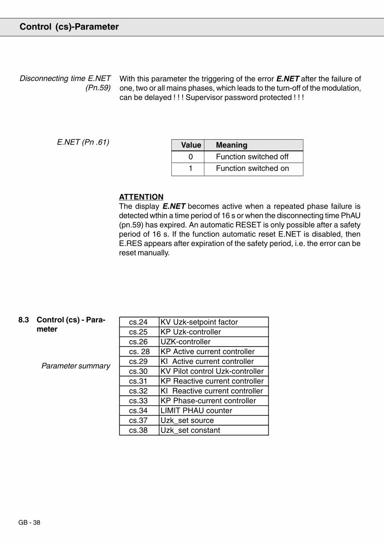
GB - 38
Disconnecting time E.NET(Pn.59)
With this parameter the triggering of the error E.NET after the failure ofone, two or all mains phases, which leads to the turn-off of the modulation,can be delayed ! ! ! Supervisor password protected ! ! !
8.3 Control (cs) - Para-meter
Parameter summary
Control (cs)-Parameter
E.NET (Pn .61) Value Meaning
0 Function switched off
1 Function switched on
ATTENTIONThe display E.NET becomes active when a repeated phase failure isdetected wthin a time period of 16 s or when the disconnecting time PhAU(pn.59) has expired. An automatic RESET is only possible after a safetyperiod of 16 s. If the function automatic reset E.NET is disabled, thenE.RES appears after expiration of the safety period, i.e. the error can bereset manually.
cs.24 KV Uzk-setpoint factorcs.25 KP Uzk-controllercs.26 UZK-controllercs. 28 KP Active current controllercs.29 KI Active current controllercs.30 KV Pilot control Uzk-controllercs.31 KP Reactive current controllercs.32 KI Reactive current controllercs.33 KP Phase-current controllercs.34 LIMIT PHAU countercs.37 Uzk_set sourcecs.38 Uzk_set constant
ANTRIEBSTECHNIK
GB - 39
KV UZK-setpoint (cs.24)
KP UZK-controller (cs.25)
KI UZK-controller (cs.26)
KP Active currentcontroller (cs.28)
KI Active current controller(cs.29)
KV Pilot control UZK-controller (cs.30)
KP Reactive currentcontroller
(cs.31)
KI Reactive currentcontroller
(cs.32)
KP Phase currentcontroller (cs.33)
The DC-link voltage setpoint is proportional to the crest value of thephase-to-phase mains voltage.
Determines the amplification of the proportional component of the UZK-controller.
Determines the amplification of the integral component of the UZK-controller.
Determines the amplification of the proportional component of the activecurrent controller.
Determines the amplification of the integral component of the activecurrent controller.
The DC-link current serves for the pilot control of the UZK-controller. Withthis factor the voltage fluctuations in the DC-link can be minimized duringdynamic processes.
Determines the amplification of the proportional component of the reactivecurrent controller.
Determines the amplification of the integral component of the reactivecontroller.
Determines the amplification of the proportional component of the phasecurrent controller.
Control (cs)-Parameter

GB - 40
Limit PHAU counter(cs.34)
Uzk_set constant (cs.38)
Uzk_set source (cs.37)
Determines the limit for the triggering of a phase failure (nEto). If duringoperation it should come to error messages inspite of optimal controllerparameterization (kp phase current controller cs.33), then this can beavoided by increasing the parameter. By writing the value 0, the function„phase failure detection“ is disabled during modulation release.
Determines the source of the setpoint value for the voltage Uzk.
Value Meaning
0 Uzk_set (CS.38)
1 Uzk_set = f(Ûmains . CS.24)
Preadjustment of a constant setpoint value for the DC-link voltage.
Control (cs)-Parameter
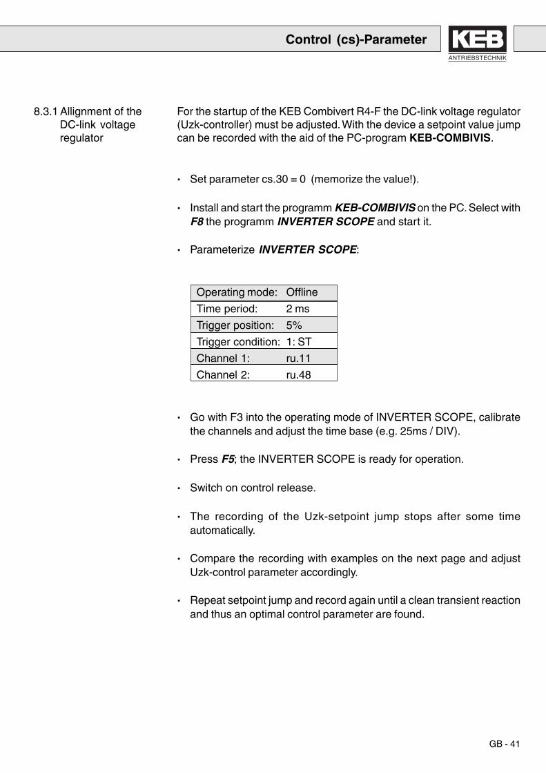
ANTRIEBSTECHNIK
GB - 41
For the startup of the KEB Combivert R4-F the DC-link voltage regulator(Uzk-controller) must be adjusted. With the device a setpoint value jumpcan be recorded with the aid of the PC-program KEB-COMBIVIS.
· Set parameter cs.30 = 0 (memorize the value!).
· Install and start the programm KEB-COMBIVIS on the PC. Select withF8 the programm INVERTER SCOPE and start it.
· Parameterize INVERTER SCOPE:
Operating mode: Offline
Time period: 2 ms
Trigger position: 5%
Trigger condition: 1: ST
Channel 1: ru.11
Channel 2: ru.48
· Go with F3 into the operating mode of INVERTER SCOPE, calibratethe channels and adjust the time base (e.g. 25ms / DIV).
· Press F5; the INVERTER SCOPE is ready for operation.
· Switch on control release.
· The recording of the Uzk-setpoint jump stops after some timeautomatically.
· Compare the recording with examples on the next page and adjustUzk-control parameter accordingly.
· Repeat setpoint jump and record again until a clean transient reactionand thus an optimal control parameter are found.
8.3.1 Allignment of theDC-link voltageregulator
Control (cs)-Parameter

GB - 42
Problem: continuous oscillation with highamplitude
Abhilfe: reduce I-component (CS.26)
Problem: too slow transient reaction/ permanent offset
Remedy: increase I-component (CS.26)
Problem: very long transient reactionRemedy: Increase P-component (CS.25);
if necessary, reduce I-component(CS.26)
Problem: too high voltage overshootRemedy: increase P-component (CS.25) ;
if necessary, reduce I-component(CS.26)
Problem: too long overshootRemedy: increase I-component (CS.26)
Problem: continuous oscillation at constant runRemedy: reduce P-component (CS.25)
8.3.2 Adjusting help DC-link voltage controller
Control (cs)-Parameter

ANTRIEBSTECHNIK
GB - 43
In order to minimize DC-link voltage fluctuations due to load fluctuations,the parameter cs.30 (kv precontrol Uzk-controller) can be adjusted. If theresult is not satisfying, the active current control parameters cs.28 andcs.29 are to be increased.
But note: Control system can start to oscillate.
In order to compensate deviations of the current characteristic from thesine-wave form, the parameter cs.33 (kv phase current controller) mustbe adjusted. If no oscilloscope is available to represent the mains current,the parameter ru.9 (apparent current) can be used as substitute. For itapplies:
The smaller the fluctuations at constant load, the sinusoidal the currentcharacteristic.
8.3.3 Improve dynamic
8.3.4 Optimize currentcharacteristic
8.4 Drive (ds)-Parameter
Parameter summary
Switching frequency(ds.13)
8.5 Free-programmable(Fr) Parameter
Parameter summary
Parameter ds.13 is an initialization parameter, i.e. new parameter valuesbecome active only after switching off the unit.
An increase of the switching frequency from 8 kHz to 16 kHz entailsan increase of the switching losses and thus a reduction of the ratedpower of the COMBIVERT R4-F. Moreover the series inductance andthe filter must be designed for the switching frequency of 16 kHz.
The function init.def copies the basic adjustments stored in the EPROMinto the SET 0, i.e. the control parameters of the CS-group with theirdefault values are also loaded.
Following restriction applies to copying the set:init can only be executed at ‘noP’ or ‘syn’.
Copy Set (Fr.0, Fr.1)
Drive (ds)-Parameter / Free-programmable (Fr)-Parameter
ds.13 Switching frequency
Fr.0 Copy keyboard parameter setFr.1 Copy bus parameter set
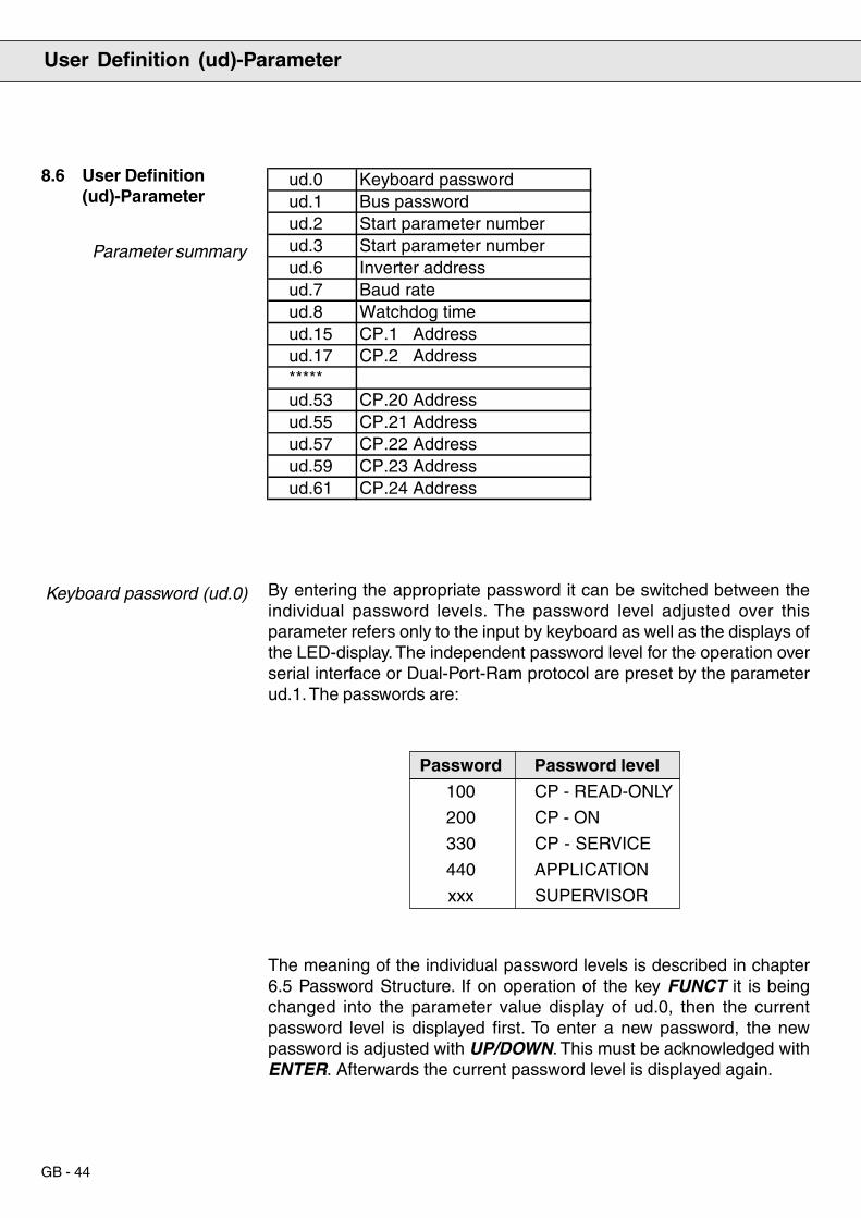
GB - 44
8.6 User Definition(ud)-Parameter
Parameter summary
Keyboard password (ud.0) By entering the appropriate password it can be switched between theindividual password levels. The password level adjusted over thisparameter refers only to the input by keyboard as well as the displays ofthe LED-display. The independent password level for the operation overserial interface or Dual-Port-Ram protocol are preset by the parameterud.1. The passwords are:
Password Password level
100 CP - READ-ONLY
200 CP - ON
330 CP - SERVICE
440 APPLICATION
xxx SUPERVISOR
The meaning of the individual password levels is described in chapter6.5 Password Structure. If on operation of the key FUNCT it is beingchanged into the parameter value display of ud.0, then the currentpassword level is displayed first. To enter a new password, the newpassword is adjusted with UP/DOWN. This must be acknowledged withENTER. Afterwards the current password level is displayed again.
User Definition (ud)-Parameter
ud.0 Keyboard passwordud.1 Bus passwordud.2 Start parameter numberud.3 Start parameter numberud.6 Inverter addressud.7 Baud rateud.8 Watchdog timeud.15 CP.1 Addressud.17 CP.2 Address*****ud.53 CP.20 Addressud.55 CP.21 Addressud.57 CP.22 Addressud.59 CP.23 Addressud.61 CP.24 Address

ANTRIEBSTECHNIK
GB - 45
The keyboard password can also be adjusted via the serial interface orthe Dual-Port-Ram protocol. This input corresponds to the input viakeyboard, i.e. after adjusting the password by bus the LED displaydisplays the current keyboard password level and changes uponoperation of FUNCT to ud.0 respectively cP.0.
By way of the bus password ud.1 the password levels for the operationover serial interface or Dual-Port-Ram protocol are adjusted. Thepassword levels CP-ON, APPLICATION and SUPERVISOR are possible.The passwords and the meaning of the password levels correspond tothose of the keyboard passwords. The bus password is not visible duringkeyboard operation.
With the parameters start parameter group and start parameter numberthe parameter is selected, which is displayed after switching on theinverter. For that the desired parameter group is adjusted in ud.2 and thedesired parameter number in ud.3. The parameter set is always set 0. Ifthe combination of ud.2 and ud.3 results in a parameter that is notavailable or if the current password level at switch on is not sufficient todisplay the parameter, then the inverter starts with the display of ru.0.
If a password level < 3 is active when switching on the inverter, i.e. displayof the user-defined parameter group, then the adjustment of ud.2 isignored, ud.3 indicates the parameter number of the cP-parameter, whosevalue shall be displayed at the starting. If this parameter is not available,then cP.0 is displayed.
With ud.6 the address is adjusted, under which the inverter is addressedby „KEB COMBIVIS“ or another control. Values between 0 and 239 arepossible, the default value is 1. If several inverters are operated on theBus at the same time, it is absolutely necessary to assign them differentaddresses, since otherwise it can result in faulty communication, becauseunder certain conditions several inverters may respond simultaneously.Further information is contained in the description of the DIN66019-Protocol.
Bus password (ud.1)
Start parameter
(ud.2, ud.3)
Inverter address (ud.6)
User Definition (ud)-Parameter

GB - 46
Baud rate (ud.7)
Watchdog time (ud.8)
Following values for the baud rate of the serial interface are possible:
Parameter value Baud rate
0 1200 baud
1 2400 baud
2 4800 baud
3 9600 baud
4 19200 baud
If the value for the baud rate is changed over the serial interface, it canbe changed again only over the keyboard or after adjustment of the baudrate of the master, since no communication is possible with different baudrates of master and slave.
For a constant control of the communication it is possible to trigger anerror message of the inverter after the expiration of an adjustable timewithout incoming telegrams. By adjusting the value 0 (off) the functioncan be deactivated.
8.7 Analog I/O (An)-Parameter
Parameter summary
Flow chart analog outputs
Characteristic amplifier ofthe analog outputs
(An.15 - An.16)
Offset X
Offs
et Y
+100 %
+100 %
-100 %
-100 %
Output value
GAINAn.15
An.16
Input valueAn.14
AN-OUTAn.15An.16
An.14
Analog I/O (An)-Parameter
An.14 Analog Out 1 FunctionAn.15 Analog Out 1 GainAn.16 Analog Out 1 Offset X

ANTRIEBSTECHNIK
GB - 47
The rise of the characteristic curve is determined by the amplification(An.15). The offset X (An.16) is needed if signal fluctuations around abase value are to be visualized (e.g. actual value of DC-link voltageagainst setpoint value of DC-link voltage). Default in [%], resolution 0.1%.
Analog output 1Function (An.14)
Analog output 1(An.15, An.16)
With this parameter the process variable can be selected which shouldbe represented over the analog output. The resolution of the analog valuesis 10 bit, the smoothing time constant for the analog signals is approx. 5ms.
Parameter value Process variable Range of 100%
0 current load 200%
1 DC-link voltage 1000 V
8.8 Digital Input (di)-Parameter
Parameter Summary
Digital Input (di)-Parameter
di.0 Digital interference suppressor filterdi.1 NPN / PNP selectiondi.2 Input logicdi.3 Input function I1di.7 Input function IAdi.8 Input function IBdi.9 Input function ICdi.10 Input function IDdi.15 Select signal sourcedi.16 Digital input setting

GB - 48
ru. 14
di. 0 di. 2
ru. 16
di. 15di. 16
Selection of PNP or NPN logic for the input terminals.
Parameter value Logic of the input terminal
0 NPN
1 PNP
Input processing
Digital noise filter (di.0)
NPN/PNP-Selection (di.1)
The digital filter reduces the sensitivity to interferences at the controlinputs. With this parameter the response time of the inputs is adjusted.During the response time a constant input status must exist at all inputsbefore the signal is accepted as valid.
Signals atcontrol terminal strip
Signals atcontrol terminal strip
Signals atcontrol terminal strip
TerminalStrip
Parameter
Scanning
Inputterminalstatus
Selectionsignalsource
Digital filter Input logic
Internalinput
status
Process input
11 t4 ms
I1
RST
10987654321
pos. edge = scantime for the inputsignalsFilter time 16 ms
Digital Input (di)-Parameter

ANTRIEBSTECHNIK
GB - 49
Bit-Coded Parameterdi.2, di.14 - di.18
Input functions(di.3 - di.10)
Input logic (di.2)
With the bit-coded di. parameters the appropriate decimal value isadjusted for each input for which the corresponding function is to beactivated. If the function should be valid for several inputs, the sum of thedecimal value is adjusted. Exceptions apply to input ST which aredescribed at the individual parameters. Following assignment applies:
Bit - No. Decimal value Input
0 1 ST
1 2 RST
4 16 I1
With this parameter it is adjusted whether an input signal is 1- or 0-active(inverted). Input ST is not inverted!
With these parameters the function of the programmable inputs (I1 to I4)and the programmable software inputs (IA, IB, IC, ID) are adjusted.
Parameter value Input function
0 no function
1 input triggers external error (E.EF)
In the parameter di.15 it can be selected for each input, whether the statusof the control terminal strip or the status of parameter di. 16 is evaluated.
Over di.16 inputs can be set via software. For this the correspondinginputs must be selected in di.15.
Exception: Input ST. If digital input of control release is adjusted (Bit 0 ofdi.15 = 1), the signal must be preset via terminal strip and parameterdi.16 (Bit 0)!
Select Signal Source(di.15)
Digital Input Setting (di.16)
Digital Input (di)-Parameter
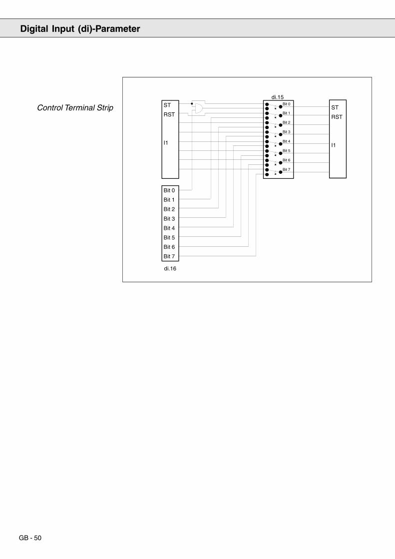
GB - 50
Control Terminal Strip ST
RST
I1
Bit 0
Bit 1
Bit 2
Bit 3
Bit 4
Bit 5
Bit 6
di.16
Steuerklemmleiste
Bit 1
Bit 2
Bit 3
Bit 4
Bit 5
Bit 6
di.15Bit 0
ST
RST
I1
Bit 7
Bit 7
Digital Input (di)-Parameter

ANTRIEBSTECHNIK
GB - 51
Output logic (do.0) Bit - No. Decimal value Output Terminal
0 1 Out 1 (Transistor output) 12
1 2 Out 2 (Relay RLA,RLB,RLC) 1, 2, 3
2 4 Out 3 (Relay FLA,FLB,FLC) 21, 22, 23
4 16 Out A (Internal output A) none
5 32 Out B (Internal output B) none
6 64 Out C (Internal output C) none
7 128 Out D (Internal output D) none
For each output that is to be inverted the corresponding decimal value isadjusted. If several outputs should be inverted, the sum of the decimalvalues is adjusted.
8.9 Digital Output (do)-Parameter
Parameter Summary
The output logic enables the inverting of the digital outputs. The parameteris bit-coded.
Digital Output (do)-Parameter
do.0 Output logicdo.1 Switching condition 1do.2 Switching condition 2do.3 Switching condition 3do.4 Switching condition 4do.9 Select switching condition Out 1 do.10 Select switching condition Out 2do.11 Select switching condition Out 3 do.13 Select switching condition Out A do.14 Select switching condition Out Bdo.15 Select switching condition Out Cdo.16 Select switching condition Out Ddo.17 Logic switching condition Out 1 do.18 Logic switching condition Out 2do.19 Logic switching condition Out 3 do.21 Logic switching condition Out A do.22 Logic switching conditionOut B do.23 Logic switching conditon Out Cdo.24 Logic switching condition Out D do.25 Linkage of switching conditions

GB - 52
Bit-No. Decimal value Switching condition
0 1 do.1
1 2 do.2
2 4 do.3
3 8 do.4
Several conditions can also apply to one output. In that case the sum ofthe decimal value is to be adjusted.
From attaining a specific operating status of the inverter (e.g.apparent current > apparent current level) to the generation of thecorresponding output signal a processing time of some ms can goby.
In order to activate a switching condition for the appropriate output, therespective decimal value is adjusted in the parameter „select switchingcondition OutX“. The status of the switching condition is displayed inparameter ru.17. Each switching condition can be inverted by adjustingthe corresponding decimal value in the parameter „logic of switchingcondition OuX“.
Swtiching Condition 4(do.1 - do.4)
With these parameters the switching conditions are adjusted, which viaparameters do.9 to do.25 are assigned to the outputs Out 1 to Out 3 andthe internal outputs Out A to Out D:
Value Output function
0 always inactive
1 always active
2 Ready
3 Run
4 Fatal error
5 DC-link voltage > DC-link voltage level
6 Apparent current > apparent current level
7 Signal of PTC series inductance
8 Signal of heat sink temperature
9 Current controller in the limitation
10 DC-link voltage controller in the limitation
11 Any controller in the limitation
12 Utilization (ru.7) > utilization level (LE.8 ... LE.10 (15))
13 OL counter > 80%14 Phase failure
Select Switching Condition(do.9 - do.11, do.13 - do.16)
Digital Output (do)-Parameter

ANTRIEBSTECHNIK
GB - 53
Linkage of SwitchingConditions (do.25)
Example to do.0 - do.25
Adjustment:
Parameter do.25 determines, whether the switching conditions, whichare selected for an output, are linked by an AND-operation (Bit X = 1) orby an OR-operation (Bit X = 0).
Bit - No. Decimal value Output
0 1 Out 1
1 2 Out 2
2 4 Out 3
4 16 Out A
5 32 Out B
6 64 Out C
7 128 Out D
Conditions for output Out 1:Utilization > 80 % andDC-link voltage < DC-link voltage level
Conditions for output Out 2:DC-link voltage > DC-link voltage level orapparent current < apparent current level
1. Switching conditonsdo. 1 = 12 (utilization > utilization level)LE. 9 = 80 %do. 2 = 5 (DC-link voltage > DC-link voltage level)LE.24 = 700 Vdo. 3 = 14 (apparent current > apparent current level)LE.14 = 30 A
2. Select switching conditiondo. 9 (Out 1) = 3 (Bit 0 and Bit 1 set => cond. 1 and cond. 2 active)do.10 (Out 2) = 6 (Bit 1 and Bit 2 set => cond. 2 and cond. 3 active)
3. Logic of switching conditionsdo.17 (Out 1) = 2 (Bit 1 set => cond. 2 inverted)do.18 (Out 2) = 4 (Bit 2 set => cond. 3 inverted)
4. Linkage of switching conditionsdo.25 = 2 (Bit 0 = 1 => cond. for Out 1 are AND-operated
Bit 1 = 0 => cond. for Out 2 are OR-operated)
5. Logic of digital outputsdo. 0 = 0 (the outputs are not inverted)
Digital Output (do)-Parameter

GB - 54
Parameter Summary
8.10 Level (LE)-Parameter
These parameters are the comparative values for the load-dependentswitching conditions of the digital outputs. Load level 1 is valid for outputcondition 1 etc.
Value range: 0 ... 199 %Resolution: 1 %
These parameters are the comparative values for the apparent current-dependent switching conditions of the digital outputs. Apparent currentlevel 1 is valid for output condition 1 etc.
Value range: 0 ... 150 AResolution: 0.1 A
These parameters are the comparative values for the DC-link voltage-dependent switching conditions of the digital outputs. DC-link voltagelevel 1 is valid for output condition 1 etc.
Value range: 0 ... 1000VResolution: 1V
With this parameter the height of the current hysteresis is adjusted.
Value range: 0 ... 150 AResolution: 0.1A
Load Level 1-4(LE.8 - LE.11)
Apparent Current Level1-4 (LE.12 - LE.15)
DC-link voltage-level 1-4(LE.24 - LE.27)
Current hysteresis (LE.38)
Level (LE)-Parameter
LE.8 Load level 1LE.9 Load level 2LE.10 Load level 3LE.11 Load level 4LE.12 Apparent current level 1LE.13 Apparent current level 2LE.14 Apparent current level 3LE.15 Apparent current level 4LE.24 DC-link voltage level 1LE.25 DC-link voltage level 2LE.26 DC-link voltage level 3LE.27 DC-link voltage level 4LE.38 Current hysteresis

ANTRIEBSTECHNIK
GB - 55
8.11 Information (In)-Parameter
Parameter Summary
Inverter Type (In.0)
Information (In)-Parameter
Bit-No. Meaning0 Voltage class 0 = 200 V, 1 = 400 V
1...5 Unit size6...8 Type of control card 3 = OC.R4
9 Expension10 free
11...12 Max. switch.frequency 0 = 2 kHz, 1 = 4 kHz,2 = 8 kHz, 3 = 16 kHz
13...15 Type of housing = G = H = K= L = M = N= R = D
In.0 Inverter typeIn.1 Inverter rated currentIn.3 max. switching frequencyIn.4 Software identificationIn.5 Software dateIn.6 Config-file-no.In.7 Serial No. (Date)In.8 Serial No. (Counter)In.9 Serial No. (AB-No. high)In.10 Serial No. (AB-No. low)In.11 Customer No. (high)In.12 Customer No. (low)In.13 QS - NumberIn.40 Last errorIn.41 Error counter OCIn.42 Error counter OLIn.43 Error counter OPIn.44 Error counter OHIn.45 Error counter WD

GB - 56
Software Date (In.5)
Configfile Number (In.6)
Serial Number,Customer Number
(In.7 - In.12),QS-Number (In.13)
Error Counter (In.40 -In.45)
Displays the software date. The value consists of the day, the month andthe year. But only the last 2 digits of the year are shown.
Example: Display = 1507.4Date = 15.07.94
This parameter serves for the identification of the software used on thecontrol by KEB COMBIVIS. The configuration occurs automatically withthe call of COMBIVIS and connected inverter.
Serial number and customer number identify the inverter. The QS-numbercontains production-internal information.
Error counters (for E.OC, E.OL, E.OP, E.OH, E.buS) specify the totalnumber of occurred errors of each type. The maximum number is 255.
Information (In)-Parameter
Inverter Rated Current(In.1)
Max. Switching Frequency(In.3)
Software Identification(In.4)
Displays inverter rated current in A (resolution 0.1 A).
Displays the maximum possible switching frequency for this inverter inkHz (resolution 1 kHz).
Software version number and control hardware are encoded in thisparameter.

ANTRIEBSTECHNIK
GB - 57
Parameter Summary
9. Parameter Summary
9.1 Table ru-Parameter
Defaultvalue
Resolution
UnitParameter address
Upper limit
Lower limit
Parameter Addr. min max Step default [?]
ru0 Inverter status 2000h – 0 200 table – –
ru7 Actual load 2007h – 0 200 0.1 – %
ru8 Peak load 2008h yes 0.1 – %
ru9 Apparent current 2009h – 0.1 – A
ru10 Active current 200Ah – 0.1 – A
ru11 DC-link voltage 200Bh – 1 – V
ru12 DC-link voltage peak value 200Ch yes 1 – V
ru14 Input terminal status 200Eh – table – –
ru15 Output terminal status 200Fh – table – –
ru16 Internal input status 2010h – table – –
ru17 Internal output status 2011h – table – –
ru24 Display OL-counter 2012h – 0,0 100 0.1 – %
ru25 Apparent current/peak value 2019h yes 0.1 – A
ru29 Heat sink temperature 201Dh – 0 100 1 – °C
ru31 Operating hour counter 1 201Fh – 0 65535 1 – h
ru32 Operating hour counter 2 2020h – 0 65535 1 – h
ru48 Act. DC-link voltage setpoint 2030h – – – 1 – V
ru49 Electrical energy consumption 2031h yes 0 65535 1 – kWh
ru50 Electrical energy recovery 2032h yes 0 65535 1 – KWh
ru52 System frequency 2034h – 45 65 0.1 – Hz
Parameter: yes writable – read-only
Parameter: yes active after„Enter“ – immediately active

GB - 58
9.2 Table pn-Parameter
Parameter Summary
Parameter Addr. min max Step default [?]
Pn0 Automatic restart UP 2200h – table 0
Pn1 Automatic restart OP 2201h – table 0
Pn16 Disconnect time error E.dOH 2216h – 0 120 60
Pn23 Response to Watchdog 2217h – yes 0 7 1 6 –
Pn25 Response to dOH error 2219h – yes 0 7 1 6 –
Pn26 Response to OH error 221Ah – yes 0 7 1 6 –
Pn59 Delay time E.net 223bh – 0 1,00 0,01 0 sec.
Pn61 Automatic restart E.net 223dh – 0 1 1 0 –
9.3 Table cs-Parameter
Parameter Addr. min max Step default [?]
CS24 KV UZK_set 2D18h – 1.05 1.70 0.1 1,20
CS25 KP UZK 2D19h – 0 65535 1 2000 –
CS26 KI UZK 2D1Ah – 0 65535 1 80 –
CS28 KP ID 2D1Ch – 0 65535 1 1500 –
CS29 KI ID 2D1Dh – 0 65535 1 100 –
CS30 KV UZK_izk 2D1Eh – 0 130 1 50 –
CS31 KP IQ 2D1Fh – 0 65535 1 200 –
CS32 KI IQ 2D20h – 0 65535 1 6 –
CS33 KP I_uvw 2D21h – 0 65535 1 50000 –
CS34 LIMIT PHAU COUNTER 2D22h – 0 32767 1 1500 –
CS37 UZK_set source 2D25h – yes 0 1 1 0 –
CS38 UZK_set constant 2D26h – yes 210 720 1 LTK V

ANTRIEBSTECHNIK
GB - 59
9.4 Table ud-Parameter
Parameter Summary
Parameter Addr. min max Step default [?]
ud0 Keyboard password 2600h yes yes 0 9999 1 0 –
ud1 Bus password 2601h yes yes 0 9999 1 0 –
ud2 Start parameter group 2602h yes – ru table table ru –
ud3 Start parameter number 2603h yes – 0 255 table 1 –
ud6 Inverter address 2606h yes yes 0 239 1 1 –
ud7 Baud rate 2607h yes yes 1200 57600 table 9600 Baud
ud8 Watchdog Time 2608h yes yes 0 : off 10,00 0.01 0 : off sec.
ud13 cP.0 address 260Dh yes yes – – 1 2600 (cp.0) –
ud15 cP.1 address 260Fh yes yes 0 7FFFF 1 2000 (ru.00) –
ud17 cP.2 address 2611h yes yes -1 : off 7FFFF 1 200B (ru.11) –
ud19 cP.3 address 2613h yes yes 0 7FFFF 1 200C (ru.12) –
ud21 cP.4 address 2615h yes yes 0 7FFFF 1 2030 (ru.48) –
ud23 cP.5 address 2617h yes yes 0 7FFFF 1 2D25 (cs.37) –
ud25 cP.6 address 2619h yes yes 0 7FFFF 1 2D1C (cs.28) –
ud27 cP.7 address 261Bh yes yes 0 7FFFF 1 2D1B (cs.27) –
ud29 cP.8 address 261Dh yes yes 0 7FFFF 1 2D19 (cs.25) –
ud31 cP.9 address 261Fh yes yes 0 7FFFF 1 2D1A (cs.26) –
ud33 cP.10 address 2621h yes yes 0 7FFFF 1 2D20 (cs.32) –
ud35 cP.11 address 2623h yes yes 0 7FFFF 1 2D1E (cs.30) –
ud37 cP.12 address 2625h yes yes 0 7FFFF 1 2009 (ru.09) –
ud39 cP.13 address 2627h yes yes 0 7FFFF 1 2007 (ru.07) –
ud41 cP.14 address 2629h yes yes 0 7FFFF 1 201B (ru.29) –
ud43 cP.15 address 262Bh yes yes 0 7FFFF 1 280E (an.14) –
ud45 cP.16 address 262Dh yes yes 0 7FFFF 1 280F (an.15) –
ud47 cP.17 address 262Fh yes yes 0 7FFFF 1 2903 (di.03) –
ud49 cP.18 address 2631h yes yes 0 7FFFF 1 2A01 (do.01) –
ud51 cP.19 address 2633h yes yes 0 7FFFF 1 2A02 (do.02) –
ud53 cP.20 address 2635h yes yes 0 7FFFF 1 2A09 (do.09) –
ud55 cP.21 address 2637h yes yes 0 7FFFF 1 2A0A (do.10) –
ud57 cP.22 address 2639h yes yes 0 7FFFF 1 2B08 (le.08) –
ud59 cP.23 address 263Bh yes yes 0 7FFFF 1 2B0C (le.12) –
ud61 cP.24 address 263Dh yes yes 0 7FFFF 1 2B18 (le. 24) –
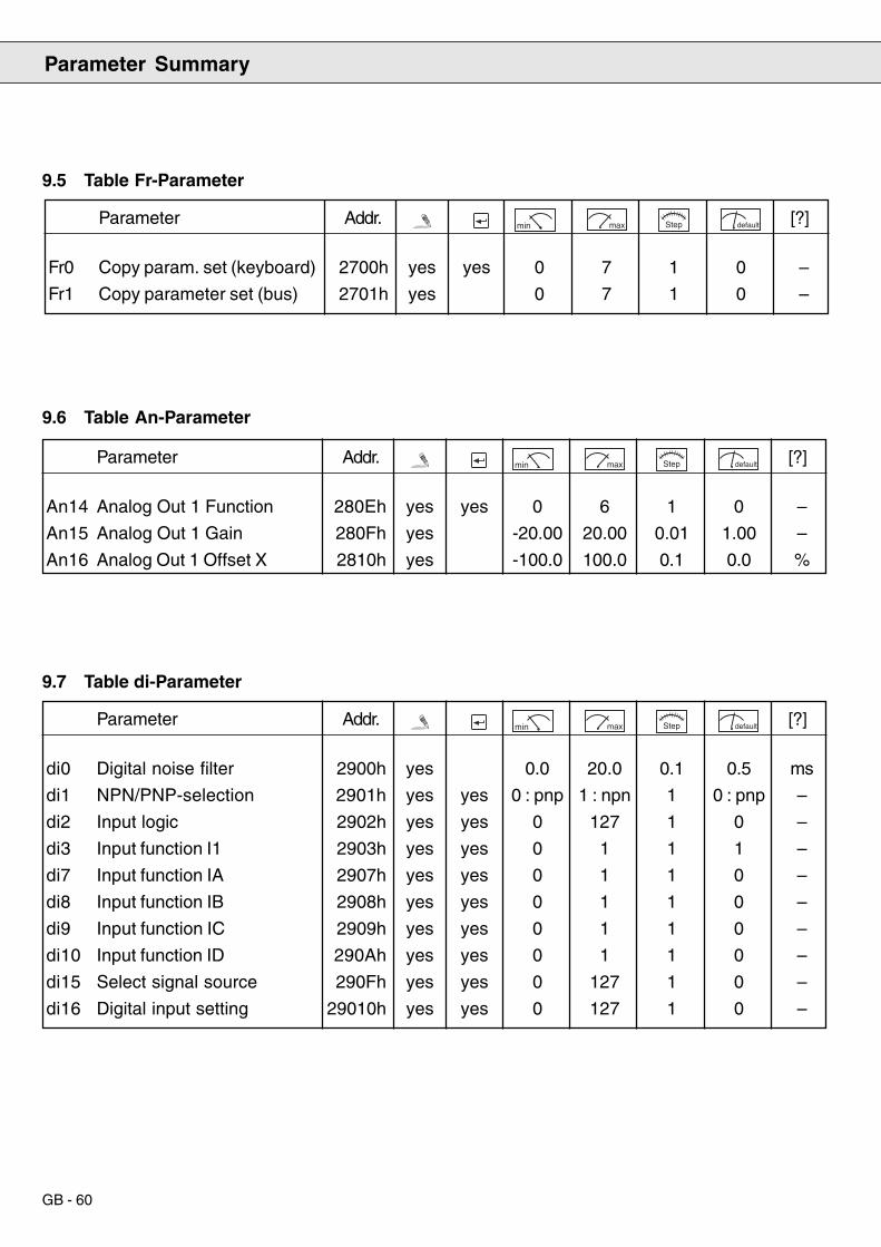
GB - 60
9.5 Table Fr-Parameter
9.6 Table An-Parameter
9.7 Table di-Parameter
Parameter Summary
Parameter Addr. min max Step default [?]
Fr0 Copy param. set (keyboard) 2700h yes yes 0 7 1 0 –
Fr1 Copy parameter set (bus) 2701h yes 0 7 1 0 –
Parameter Addr. min max Step default [?]
An14 Analog Out 1 Function 280Eh yes yes 0 6 1 0 –
An15 Analog Out 1 Gain 280Fh yes -20.00 20.00 0.01 1.00 –
An16 Analog Out 1 Offset X 2810h yes -100.0 100.0 0.1 0.0 %
Parameter Addr. min max Step default [?]
di0 Digital noise filter 2900h yes 0.0 20.0 0.1 0.5 ms
di1 NPN/PNP-selection 2901h yes yes 0 : pnp 1 : npn 1 0 : pnp –
di2 Input logic 2902h yes yes 0 127 1 0 –
di3 Input function I1 2903h yes yes 0 1 1 1 –
di7 Input function IA 2907h yes yes 0 1 1 0 –
di8 Input function IB 2908h yes yes 0 1 1 0 –
di9 Input function IC 2909h yes yes 0 1 1 0 –
di10 Input function ID 290Ah yes yes 0 1 1 0 –
di15 Select signal source 290Fh yes yes 0 127 1 0 –
di16 Digital input setting 29010h yes yes 0 127 1 0 –
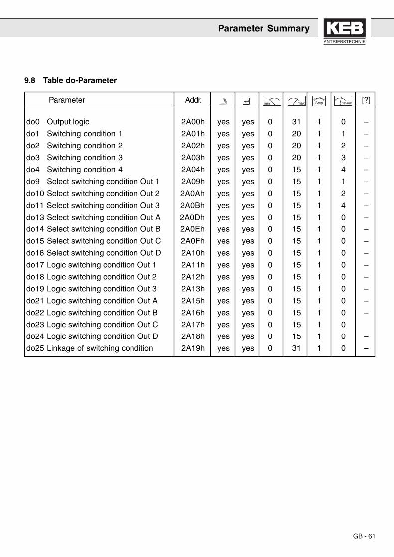
ANTRIEBSTECHNIK
GB - 61
9.8 Table do-Parameter
Parameter Summary
Parameter Addr. min max Step default [?]
do0 Output logic 2A00h yes yes 0 31 1 0 –
do1 Switching condition 1 2A01h yes yes 0 20 1 1 –
do2 Switching condition 2 2A02h yes yes 0 20 1 2 –
do3 Switching condition 3 2A03h yes yes 0 20 1 3 –
do4 Switching condition 4 2A04h yes yes 0 15 1 4 –
do9 Select switching condition Out 1 2A09h yes yes 0 15 1 1 –
do10 Select switching condition Out 2 2A0Ah yes yes 0 15 1 2 –
do11 Select switching condition Out 3 2A0Bh yes yes 0 15 1 4 –
do13 Select switching condition Out A 2A0Dh yes yes 0 15 1 0 –
do14 Select switching condition Out B 2A0Eh yes yes 0 15 1 0 –
do15 Select switching condition Out C 2A0Fh yes yes 0 15 1 0 –
do16 Select switching condition Out D 2A10h yes yes 0 15 1 0 –
do17 Logic switching condition Out 1 2A11h yes yes 0 15 1 0 –
do18 Logic switching condition Out 2 2A12h yes yes 0 15 1 0 –
do19 Logic switching condition Out 3 2A13h yes yes 0 15 1 0 –
do21 Logic switching condition Out A 2A15h yes yes 0 15 1 0 –
do22 Logic switching condition Out B 2A16h yes yes 0 15 1 0 –
do23 Logic switching condition Out C 2A17h yes yes 0 15 1 0
do24 Logic switching condition Out D 2A18h yes yes 0 15 1 0 –
do25 Linkage of switching condition 2A19h yes yes 0 31 1 0 –

GB - 62
Parameter Summary
9.9 Table LE-Parameter
Parameter Addr. min max Step default [?]
LE8 Load level 1 2B08h yes 0.0 200 1 0 %
LE9 Load level 2 2B09h yes 0.0 200 1 0 %
LE10 Load level 3 2B0Ah yes 0.0 200 1 0 %
LE11 Load level 4 2B0Bh yes 0.0 200 1 0 %
LE12 Apparent current level 1 2B0Ch yes 0.0 50.0 0.1 0 A
LE13 Apparent current level 2 2B0Dh yes 0.0 50.0 0.1 0 A
LE14 Apparent current level 3 2B0Eh yes 0.0 50.0 0.1 0 A
LE15 Apparent current level 4 2B0Fh yes 0.0 50.0 0.1 0 A
LE24 DC-link voltage 1 2B18h yes 0.0 2025 1 0 V
LE25 DC-link voltage 2 2B19h yes 0.0 2025 1 0 V
LE26 DC-link voltage 3 2B1Ah yes 0.0 2025 1 0 V
LE27 DC-link voltage 4 2B1Bh yes 0.0 2025 1 0 V
LE38 Current hysteresis 2B26h yes 0.0 150 0.1 0.2 A

ANTRIEBSTECHNIK
GB - 63
9.11 Table Supervisor-Parameter
These parameters are changeable only with supervisor password and hardlock.
9.10 Table In-Parameter
Parameter Summary
Parameter Addr. min max Step default [?]
In0 Inverter type 2C00h – table Name plate –
In1 Inverter rated current 2C00h – 0 370 0.1 LTK A
In3 max. switch. frequency 2C00h – 0 16 0
In4 Software identification 2C00h – 0.1 –
In5 Software date 2C00h – 0.1 –
In6 Configfile No. 2C00h – 0 255 1 69 –
In7 Serial No. (Date) 2C00h – 0 65535 1 0 –
In8 Serial No. (Counter) 2C00h – 0 65535 1 0 –
In9 Serial No. (AB-No. high) 2C00h – 0 65535 1 0 –
In10 Serial No. (AB-No. low) 2C00h – 0 65535 1 0 –
In11 Customer number (high) 2C00h – 0 65535 1 0 –
In12 Customer number (low) 2C00h – 0 65535 1 0 –
In13 QS Number 2C00h – 0 255 1 0 –
In40 Last error 2C00h – 0 63 1 0 –
In41 Error counter OC 2C00h – 0 255 1 0 –
In42 Error counter OL 2C00h – 0 255 1 0 –
In43 Error counter OP 2C00h – 0 255 1 0 –
In44 Error counter OH 2C00h – 0 255 1 0 –
In45 Error counter WD 2C00h – 0 255 1 0 –
In46 Last Hardlock 2C00h – 0 255 1 0 –
In47 Password level 0 2C00h – 0 9999 1 –
In48 Password level 1 2C00h – 0 9999 1 –
In49 Password level 2 2C00h – 0 9999 1 –
In50 Password level 3 2C00h – 0 9999 1 –
In54 soft. ver. dsp 2C00h – 0 255 1
In55 soft. date dsp 2C00h – 0 32767 1
Parameter Addr. min max Step default [?]
In25 Analog Output Offset 2C1Ah yes 0 255 1 250
In26 Analog Output Gain 2C1Bh yes 0 255 1 147
In32 Offset Synchronization 2C1Fh yes 0 65536 1 0

GB - 64
Danger to Life
Out of Service, Demounting and Waste Disposal
No extraordinary maintenance is required.
1. Ensure standstill of the drive – frequency inverter2. Deactivate control – KEB COMBIVERT R4-F, terminal ST3. Disconnect mains – main contactor
When dismantling the KEB COMBIVERT R4-F please pay specialattention to the capacitor discharge time!
Before starting to work on the plant, the safe isolation from supply mustbe verified with measurements in the system!
All installation and connection work must be done when the system isswitched off!
The intermediate circuit capacitors of the KEB-COMBIVERT R4-F arestill charged with high voltage for a short period of time. The unit can beworked on again, after it has been switched off for 5 minutes.
The KEB COMBIVERT R4-F does not contain PCB elements.The waste disposal items must be given to a special waste disposal!
10. Maintenance
11. Out of Service,Dismantling andWaste Disposal
Out of Service
Dismantling
Waste Disposal

ANTRIEBSTECHNIK
GB - 65
12. Error Diagnosis
Reason
DC-link voltage has fallen below the permissible value- input voltage too small or instable- voltage losses due to incorrect cabling
DC-link voltage has risen above the permissible value- input voltage too high- interference voltages at input
Happens when the specified peak current is exceeded or an earthfault occurred.
Happens when an excessive load is applied longer than for thepermissible time (see parameter ru. 24)- error or overload in the application- R4-F feed-in and feedback unit is wrongly dimensioned
After error E.OL a cooling phase must be waited for.This message is displayed after the cooling phase is completed.The error can be reset.
Happens when the cooling temperature > 90 °C.- insufficient cooling- ambient temperature too high
No internal overtemperature error.Error E.OH can be reset.
External overtemperature error is triggered when the commutatingchoke is overheated.- ambient temperature too high.- mains commutating choke dimensioned wrongly.
If this message is displayed without the error signal defined by the user,the following can happen.- Interference voltages at the input.Remedy: Increase of digital interference suppression filter (parameter di. 0).
Happens when phases of the mains supply conductor andsynchronization lines are incorrectly allocated.Remedy: Correction of allocation.
Happens when mains supply conductors are not connected or duringmains failure the disconnecting time has elapsed (parameter Pn.59).
Hold-off time elapsed, manual reset necessary.
Error Term
Undervoltage E.UP
Overvoltage E.OP
Overcurrent E.OC
Overload E.OL
Cooling time E.nOLfinished
Overtemperature E.OH
No Over- E.nOHtemperature
Overtemperature E.dOHcommutation-choke
External error E.EF
Synchronization E.SYn
Mains failure E.net
Reset E.RES

GB - 66
Memo

ANTRIEBSTECHNIK
Memo

© K
EB
00
.R4.
F1A
-K10
0 0
6/20
01
Karl E. Brinkmann GmbHFörsterweg 36 - 38 • D - 32683 Barntrup
Telefon 00 49 / 52 63 / 4 01 - 0 • Fax 00 49 / 52 63 / 4 01 - 1 16Internet: www.keb.de • E-mail: [email protected]
KEB Antriebstechnik GmbH & Co. KGWildbacher Str. 5 • D - 08289 Schneeberg
Telefon 0049 / 37 72 / 67 - 0 • Telefax 0049 / 37 72 /67 - 2 81E-mail: [email protected]
KEB Antriebstechnik Austria GmbHRitzstraße 8 • A - 4614 Marchtrenk
Tel.: 0043 / 7243 / 53586 - 0 • FAX: 0043 / 7243 / 53586 - 21Kostelni 32/1226 • CZ - 370 04 Ceské Budejovice
Tel.: 00420 / 38 / 731 92 23 • FAX: 00420 / 38 / 733 06 97E-mail: [email protected]
KEB AntriebstechnikHerenveld 2 • B - 9500 Geraadsbergen
Tel.: 0032 / 5443 / 7860 • FAX: 0032 / 5443 / 7898E-mail: [email protected]
KEB ChinaXianxia Road 299 • CHN - 200051 Shanghai
Tel.: 0086 / 21 / 62350922 • FAX: 0086 / 21 / 62350015Internet: www.keb-cn.com • E-mail: [email protected]
Société Française KEBZ.I. de la Croix St. Nicolas • 14, rue Gustave Eiffel
F - 94510 LA QUEUE EN BRIETél.: 0033 / 1 / 49620101 • FAX: 0033 / 1 / 45767495
E-mail: [email protected]
KEB (UK) Ltd.6 Chieftain Buisiness Park, Morris Close
Park Farm, Wellingborough, GB - Northants, NN8 6 XFTel.: 0044 / 1933 / 402220 • FAX: 0044 / 1933 / 400724
Internet: www.keb-uk.co.uk • E-mail: [email protected]
KEB Italia S.r.l.Via Newton, 2 • I - 20019 Settimo Milanese (Milano)
Tel.: 0039 / 02 / 33500782 • FAX: 0039 / 02 / 33500790Internet: www.keb.it • E-mail: [email protected]
KEB - YAMAKYU Ltd.711 Fukudayama, Fukuda
J - Shinjo-Shi, Yamagata 996 - 0053Tel.: 0081 / 233 / 29 / 2800 • FAX: 0081 / 233 / 29 / 2802
E-mail: [email protected]
KEB PortugalLugar de Salgueiros – Pavilhao A, Mouquim
P - 4760 V. N. de FamalicaoTel.: 00351 / 252 / 371 318 • FAX: 00351 / 252 / 371 320
E-mail: [email protected]
KEB Taiwan Ltd.1F, No.19-5, Shi Chou Rd., Tounan Town
R.O.C. - Yin-Lin Hsian / TaiwanTel.: 00886 / 5 / 5964242 • FAX: 00886 / 5 / 5964240
E-mail: [email protected]
KEBCO Inc.1335 Mendota Heights Road
USA - Mendota Heights, MN 55120Tel.: 001 / 651 / 4546162 • FAX: 001 / 651 / 4546198Internet: www.kebco.com • E-mail: [email protected]