
Bodenschleifmaschine Floor Grinder - contecgmbh.com¤chentechnik/DELTA_II... · Elektromotor 6.8...
20
DELTA II Bodenschleifmaschine Floor Grinder Betriebsanleitung (Originalausgabe) Instruction manual (Original edition)
Transcript of Bodenschleifmaschine Floor Grinder - contecgmbh.com¤chentechnik/DELTA_II... · Elektromotor 6.8...
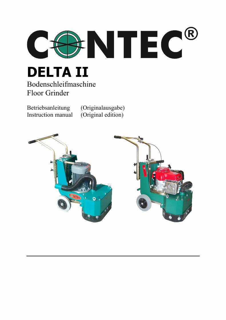
DELTA II Bodenschleifmaschine Floor Grinder
Betriebsanleitung (Originalausgabe) Instruction manual (Original edition)
Betriebsanleitung / Manual DELTA II - 2 -
© CONTEC® 2018 CONTEC Maschinenbau & Entwicklungstechnik GmbH Hauptstrasse 146, 57518 Alsdorf (Sieg) / Germany Tel: +49 (0) 2741 9344-0 Fax: +49 (0) 2741 9344-29
Inhaltsverzeichnis / Index 1. EG-Konformitätserklärung / EC-Declaration of Conformity ...3 2. Anwendungsbereich der Maschine / Machine applications ...4 3. Technische Daten / Technical data ...4 4. Sicherheitsregeln für den Betrieb der Bodenschleifmaschine / Safety rules for the operation of the floor grinder ...5 5. Inbetriebnahme und Schleifen / Operation ...8 6. Einstellung und Wartung / Adjustments and Maintenance ...10 6.1 Liftvorrichtung / Lifting device ...10
6.2 Höhenverstellung der Hinterradschwinge / Height Adjustment of the Rear Wheel Wing ...10
6.3 Verschiebung der Hinterradachse und damit Regulierung der ...10 Last auf den Werkzeugen /
Shifting the rear wheel axis and thereby regulating …10 the load on the discs and tools.
6.4 Riemenspannung / Belt tension ...11
7. Wechsel der Werkzeuge / Changing of tools ...11 8. Anhang / Appendix ...11
Betriebsanleitung / Manual DELTA II - 3 -
© CONTEC® 2018 CONTEC Maschinenbau & Entwicklungstechnik GmbH Hauptstrasse 146, 57518 Alsdorf (Sieg) / Germany Tel: +49 (0) 2741 9344-0 Fax: +49 (0) 2741 9344-29
EG-Konformitätserklärung
gemäß der EG-Maschinen-Richtlinie 2006/42/EG vom 17. Mai 2006, Anhang II A Hiermit erklären wir, dass die nachstehend bezeichnete Maschine in ihrer Konzeption und Bauart sowie in der von uns in Verkehr gebrachten Ausführung den grundlegenden Sicherheits- und Gesundheitsanforderungen der EG-Richtlinie 2006/42 EG entspricht. Bei einer mit uns nicht abgestimmten Änderung der Maschine verliert diese Erklärung ihre Gültigkeit. Hersteller: Contec Maschinenbau & Entwicklungstechnik GmbH, Hauptstraße 146, 57518 Alsdorf, Deutschland Beschreibung und Identifizierung der Maschine: Bezeichnung: Modell: Seriennummer: Baujahr: Es wird die Übereinstimmung mit weiteren, ebenfalls für das Produkt geltenden Richtlinien/Bestimmungen erklärt: EMV-Richtlinie (2004/108/EG) vom 15. Dezember 2004 Angewandte harmonisierte Normen insbesondere: DIN EN 12100 Sicherheit von Maschinen – Grundbegriffe, allgemeine Gestaltungsleitsätze, : Grundsätzliche Terminologie, Methodik, Risikobeurteilung DIN EN 60204-1 Sicherheit von Maschinen – Elektrische Ausrüstungen von Maschinen, Teil1: Allgemeine Anforderungen Bevollmächtigter für die technische Dokumentation: Johannes Greb, Technische Leitung
Alsdorf, 05.03.18
EC-Declaration of Conformity In accordance with the EEC Machine Directive 2006/42/EG of 17 May 2006, Appendix II A We hereby certify that the following described machine in its conception, construction and form put by us into circulation is in accordance with all the relevant essential health and safety requirements of the EC Machinery Directive 2006/42/EEC as amended and the national laws and regulations adopting this directive. This declaration is no longer valid if the machine is modified without our consent. Manufacturer: Contec Maschinenbau & Entwicklungstechnik GmbH, Hauptstraße 146, 57518 Alsdorf, Germany Description of the machine: Function: Model: Serial number: Year: The agreement with further valid guidelines/regulations following for the products is explained: EMV-Richtlinie (2004/108/EG) of 15. December 2004 Other applied harmonized standards and specifications in particular: DIN EN 12100 Sicherheit von Maschinen – Grundbegriffe, allgemeine Gestaltungsleitsätze, : Grundsätzliche Terminologie, Methodik, Risikobeurteilung DIN EN 60204-1 Sicherheit von Maschinen – Elektrische Ausrüstungen von Maschinen, Teil1: Allgemeine Anforderungen Authorized person for the technical documentation: Johannes Greb, Technical Manager
Alsdorf, 05.03.18
Bodenschleifmaschine DELTA II
Floor Grinder DELTA II
Betriebsanleitung / Manual DELTA II - 4 -
© CONTEC® 2018 CONTEC Maschinenbau & Entwicklungstechnik GmbH Hauptstrasse 146, 57518 Alsdorf (Sieg) / Germany Tel: +49 (0) 2741 9344-0 Fax: +49 (0) 2741 9344-29
2 Anwendungsbereich der Maschine
2 Machine applications
Schleifen von horizontalen, trockenen Böden wie Beton- und Stahlflächen mit und ohne Beschichtung und Asphalt durch Einsatz der von CONTEC® angebotenen Schleifwerk-zeuge. Der Einsatz außerhalb geschlossener Räume ist nur bei trockenem Wetter gestattet. Die Variante DELTA II-P mit Honda Verbrennungsmotor darf nur außerhalb geschlossener Räume bei trockenem Wetter verwendet werden. Der Betrieb ist nur mit einer von CONTEC® empfohlenen Absauganlage gestattet.
Grinding of horizontal, dry floors such as concrete and steel surfaces with or without a coating and asphalt using CONTEC® grinding tools. The use of the machine outside is only possible in dry weather. The DELTA II-P with Honda engine is only allowed to be operated outdoors in dry weather. The operation must only be carried out in conjunction with a from CONTEC® recommended dust collector.
3 Technische Daten
* Messwerte: VÜA Verein zur Überwachung technischer Anlagen e.V. Technische Änderungen vorbehalten
DELTA II DELTA II Spezial DELTA II-P Arbeitsbreite 490 mm 490 mm 490 mm Maschinenbreite 66 cm 66 cm 66 cm Maschinenlänge 105 cm 105 cm 105 cm Maschinenhöhe 115 cm 115 cm 115 cm Gewicht 175 kg 165 kg 160 kg Absaugstutzen ¢ 70 mm 70 mm 70 mm Elektromotor 6.8 kW, 1000 U/min
8.0 kW, 2000 U/min 7.5 kW -
Elektrischer Anschluss 400 V, 3 Phasen 400 V, 3 Phasen Honda Verbrennungsmotor - - 11 PS Schwingungsgesamtwert ahv *
4.3 m/s2 4.3 m/s2 9.3 m/s2
Schalleistungspegel Lwa * 99 dB(A) 99 dB(A) 106 dB(A) Dauerschallpegel Leq * 88 dB(A) 99 dB(A) 95 dB(A)
3 Technical data DELTA II DELTA II
Single speed DELTA II US Version
DELTA II-P
Grinding width 490 mm 490 mm 490 mm (19 in) 490 mm
Width 66 cm 66 cm 66 cm (26 in) 66 cm
Length 105 cm 105 cm 105 cm (41 in) 105 cm
Hight 115 cm 115 cm 115 cm (45 in) 115 cm
Weight 175 kg 165 kg 175 kg (385 Ibs) 160 kg
Betriebsanleitung / Manual DELTA II - 5 -
© CONTEC® 2018 CONTEC Maschinenbau & Entwicklungstechnik GmbH Hauptstrasse 146, 57518 Alsdorf (Sieg) / Germany Tel: +49 (0) 2741 9344-0 Fax: +49 (0) 2741 9344-29
Hose ¢ 70 mm 70 mm 70 mm (2.86 in) 70 mm
Motor 6.8 kW, 1000 U/min 8.0 kW, 2000 U/min
7.5 kW 9.0 kW (12 hp) -
Electric supply 400 V, 3 phases 480 V, 3 phases
400 V, 3 phases 480 V, 3 phases
230 V, 3 phases
Honda engine - - - 11 PS
Average value of acceleration ahv *
4.3 m/s2 4.3 m/s2 4.3 m/s2 9.3 m/s2
Noise level Lwa * 99 dB(A) 99 dB(A) 99 dB(A) 106 dB(A)
Noise level Leq * 88 dB(A) 99 dB(A) 99 dB(A) 95 dB(A)
* Data: VÜA Verein zur Überwachung technischer Anlagen e.V.
4 Sicherheitsregeln f. den Betrieb der Bodenschleifmaschine
4 Safety Rules for Operating the DELTA Grinder
Anwendungsbereich der Maschine:
Schleifen von horizontalen, trockenen Böden wie Beton- und Stahlflächen, mit und ohne Beschichtung und Asphalt durch Einsatz der von CONTEC® angebotenen Schleifwerk-zeuge. Der Einsatz außerhalb geschlossener Räume ist nur bei trockenem Wetter gestattet. Die Variante DELTA II-P mit Honda Verbrennungsmotor darf nur außerhalb geschlossener Räume bei trockenem Wetter verwendet werden. Achtung ! Die Bodenschleifmaschine DELTA ist unter Berücksichtigung geltender Sicherheitsstandards entwickelt worden. Die technischen Sicherheitsvorkehrungen dürfen auf keinen Fall entfernt oder verändert werden. Beim Betrieb der Schleifmaschine sollten außerdem folgende Punkte beachtet werden: 1 Die Bodenschleifmaschine darf nur von geschultem Personal betrieben werden. Diese Bedienungsanleitung muss vom Bediener gründlich durchgelesen worden sein. 2 Die Bodenschleifmaschine darf nicht im explosionsgefährdetem oder feuergefährli-chem Umfeld betrieben werden. 3 Die Bodenschleifmaschine darf nur gestartet werden wenn die Werkzeuge mittels des Hubstabs (Anhang Skizze Pos 63 und 65) vom Boden abgehoben wurden. Der Start in
Intended application and operation:
Grinding of flat, horizontal, dry surfaces that are typically concrete, asphalt or steel and with or without a coating. For optimum performance and compatibility always use tools supplied by CONTEC®. Operation of the grinder outdoors is only permitted if the weather is dry. The DELTA II-P with Honda engine is only allowed to be operated outdoors. Attention ! The DELTA floor grinders are constructed according to existing safety rules and regulations. These technical precautions must not be removed or changed under any circumstances. While operating the grinder the following points should also be kept in mind: 1 The floor grinder may only be operated by trained professionals. The operators have read and be familiar the contents of this manual. 2 The floor grinder must not be operated in areas where the hazard of explosion or fire exists. 3 The grinder should only be activated when the tools are lifted from the floor by the lifting device (Appendix diagram No. 63 and 65).
Betriebsanleitung / Manual DELTA II - 6 -
© CONTEC® 2018 CONTEC Maschinenbau & Entwicklungstechnik GmbH Hauptstrasse 146, 57518 Alsdorf (Sieg) / Germany Tel: +49 (0) 2741 9344-0 Fax: +49 (0) 2741 9344-29
vollständig gekippter Stellung ist untersagt. 4 Beim Wechsel der Werkzeuge können diese sehr heiß sein. 5 Die Bodenschleifmaschine darf nicht auf schrägem oder abfallendem Untergrund betrieben werden. 6 Beim Bewegen (rollen) auf abfallendem Untergrund muss besondere Vorsicht gelten. 7 Beim Anheben der Maschine mittels Kran dürfen nur die im Anhang „Kranösen“ beschriebenen Aufhängepunkte benutzt werden. 8 Die Maschine muss nach Gebrauch immer in einem trockenem, warmen Platz gelagert werden. 9 Die Bodenschleifmaschine darf nur mit angebrachter Schleiffeldabdichtung (Anhang Skizze Pos 1) betrieben werden. 10 Beim Verwenden von Werkzeugen, die nicht von CONTEC® geliefert wurden, erlischt die Garantie der Maschine 11 Die Bodenschleifmaschine darf nur mit sämtlichen Schutzvorrichtungen betrieben werden. 12 Bei Transport, der Reinigung, der Reparatur oder der Wartung der Maschine muss der Netzstecker gezogen werden. Dies gilt auch für den Werkzeugwechsel. 13 Der Maschinist darf sich während des Betriebs nicht von der Schleifmaschine entfernen. 14 Vor dem Verlassen der Schleifmaschine hat der Maschinist den Motor stillzusetzen und das Gerät gegen ungewollte Bewegungen zu sichern. Außerdem muss der Netzstecker gezogen werden. 15 Tragen Sie Kleidung, die fest am Körper anliegt. Flatternde Kleidungsteile können in die Maschine gelangen und in sie hineingezogen werden. 16 Werden während des Betriebs der Schleifmaschine DELTA II ungewöhnliche Laufgeräusche oder erhöhte Vibrationen registriert, muss die Maschine unverzüglich abgeschaltet werden und die Ursache des außergewöhnlichen Verhaltens ergründet werden. 17 Eine regelmäßige Kontrolle der zuführenden Stromkabel ist nötig, da diese beim Betrieb der Anlage mechanische Schäden erlitten haben könnten. (vorher
4 The tools and discs may be hot after use. Take care when changing them. 5 Never operate the floor grinder on a sloping surface. 6 Take care when moving the machine on a sloping surface, substantial rolling forces can be produced. 7 The hooks of a crane can only be placed in the lifting points described in the appendix „Lifting Points“. 8 The machine should always be stored in a warm, dry place when not in use. 9 The floor grinder may only be operated with the dust guard (Appendix diagram No.1). 10 Only CONTEC® original tools and spare parts are to be used. 11 The grinder should only be operated with all safety guards in position. 12 When changing tools, during transportation, cleaning, repair or maintenance the grinder must be disconnected from the mains. 13 The operator must never leave the machine unattended during operation. 14 Before leaving the machine all rotary parts must be brought to a standstill. Electric models must be disconnected from the power supply. Ensure the machine cannot roll or move by itself. 15 Never wear loose or badly fitting clothing. Flapping sleeves may be pulled into the machine causing serious injury. 16 The DELTA should be switched off immediately if unusual noises or vibrations are detected during the operating of the machinery. A thorough check must be carried out in order to detect the cause. 17 Check the power cables regularly as damage may have occurred while operating the machine. Always disconnect the cables before examination and treat all electrical
Betriebsanleitung / Manual DELTA II - 7 -
© CONTEC® 2018 CONTEC Maschinenbau & Entwicklungstechnik GmbH Hauptstrasse 146, 57518 Alsdorf (Sieg) / Germany Tel: +49 (0) 2741 9344-0 Fax: +49 (0) 2741 9344-29
Netzstecker ziehen !) Behandeln Sie alle spannungsführenden Teile mit größter Sorgfalt. 18 Nach Wartungs- und Instandsetzungs-arbeiten müssen die Schutzvorrichtungen wieder ordnungsgemäß angebracht werden. 19 Es müssen Schallschutzmittel vom Maschinisten getragen werden. 20 Es muss ein Augenschutz vom Maschinisten getragen werden. 21 Es müssen Sicherheitsschuhe mit Stahlkappen vom Maschinisten getragen werden. 22 Bei größerer Staubentwicklung in geschlossenen Räumen muss die Bodenschleifmaschine mit einer Absauganlage betrieben werden. 23 Je nach Bodenart und Beschichtung können beim Schleifen Gase freigesetzt werden. Es liegt in der Verantwortung des Anwenders ob diese Gase gefährliche Stoffe enthalten können und ob Schutzmassnahmen ergriffen werden müssen. Speziell beim Schleifen von z.B. asbesthaltigen Böden müssen Maßnahmen getroffen werden, welche die Atemluft des Maschinisten rein halten. Es müssen außerdem geeignete Filter in die Absauganlagen eingesetzt werden. 24 Die zu schleifende Fläche sollte besenrein sein weil loses Material von den Schleifwerkzeugen erfasst und weggeschleudert werden könnte. Außerdem können z.B. aus dem Boden hervorragende Stifte , Schrauben und Bolzen besser erkannt werden. Damit wird die Gefahr gebannt, das die Schleifwerkzeuge mit den Teilen kollidieren und Stücke der Werkzeuge und/oder Teile weggeschleudert werden. Speziell für die Variante DELTA II-P mit Honda Verbrennungsmotor gilt: 1 Die Maschine darf nur außerhalb geschlossener Räume betrieben werden. 2 Der Verbrennungsmotor wird beim Betrieb sehr heiß. Bei Berührungen sind Verbrennungen möglich. Bedienungs-anleitung des Herstellers (beigefügt) beachten.
parts with extreme care. 18 After any maintenance and adjustment all safety guards must be refitted. 19 Ear protectors must be worn. 20 Eye protectors must be worn. 21 Safety shoes with steel caps must be worn. 22 When operating the grinder produces large volumes of dust the grinder should be connected to a suitable dust collector. 23 Depending on the floor (floor coating) grinding can produce gases. The operator must be held responsible if the gases generated are hazardous and whether protection is necessary. Grinding floors containing asbestos is especially dangerous and can cause health problems. Special masks must be worn which keep the breathing air clean. A dust collector must be used and should be equipped with filters suitable for asbestos dust. 24 The floor must be brushed before grinding to prevent loose material collecting in the tools and then being thrown out with force. Anchor screws and bolts in the floor can also be seen better if the area is clean. If the grinding head strikes an anchor screw or bolt then serious damage can be caused to the machine and grinding head. Special safety rules for the DELTA II-P with Honda engine: 1 Only operate the machine outdoors. 2 The Honda engine turns very hot during operation. Never touch the engine. Also read the manual of the Honda engine.
Betriebsanleitung / Manual DELTA II - 8 -
© CONTEC® 2018 CONTEC Maschinenbau & Entwicklungstechnik GmbH Hauptstrasse 146, 57518 Alsdorf (Sieg) / Germany Tel: +49 (0) 2741 9344-0 Fax: +49 (0) 2741 9344-29
5 Inbetriebnahme und Schleifen
5 Operating and Grinding
Die Inbetriebnahme darf nur unter Berücksichtigung der in dieser Anleitung beschriebenen Sicherheitsregeln und Vorkehrungen erfolgen ! Transportieren Sie die Schleifmaschine zu ihrem Einsatzort. Verbinden Sie die DELTA mittels des Absaugschlauchs mit der Absauganlage. Es ist wichtig, dass der Schlauch auf ganzer Länge und an den Anschlussstücken dicht ist. Kleine Löcher oder falscher Sitz der Anschlussstücke können die Saugleistung erheblich herabsetzen. Überprüfen Sie auch die elektrischen Zuleitungskabel. Verbinden Sie das Zuleitungskabel mit dem Maschinenstecker. Die Schleifmaschine DELTA II benötigt einen 32 A, 3 Phasen Anschluss. Hebeln Sie mit Hilfe des Hubstabs (Anhang Skizze Pos 63 und 65) die Werkzeuge vom Boden ab.
!
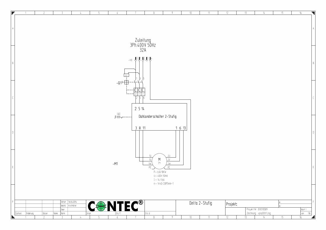
Befinden sich die Werkzeuge beim Anfahren der Schleifmaschine auf dem Boden kann es zu Beschädigungen der Werkzeuge und einiger Maschinenteile kommen ! Einschalten von DELTA II Schalten Sie den Hauptschalter (Anhang Skizze Pos 90, unterer, roter Schalter) in die Stellung 1. Dabei muss sich der Motorschalter (Anhang Skizze Pos 90, oberer, schwarzer Schalter) auf der „0“-Stellung befinden. Mit dem Motorschalter wird jetzt der Motor eingeschaltet. Bei der Version mit 2 unterschiedlichen Drehzahlen durch Schalten in die Position 1 (1000U/min) oder in die Position 2 (2000U/min). Bei der
Operating the DELTA has to be carried out according to the safety rules in Chapter 4. Bring the grinder to the floor. Connect a hose to the DELTA and to the dust collector. It is important, that the entire length of the hose has no holes and is completely air tight. Small holes or a bad connection can extremely decrease the performance Check all the electric cables. Connect the extension lead to the plug of the grinder. The power required is 400 V, 32 A, 3 phase, 50 Hz for the European version and 230 V, 26 A, 3 phase, 60 Hz for the US version. Lift the tools from the floor using the lift bar (Appendix diagram No. 63 and 65).
!
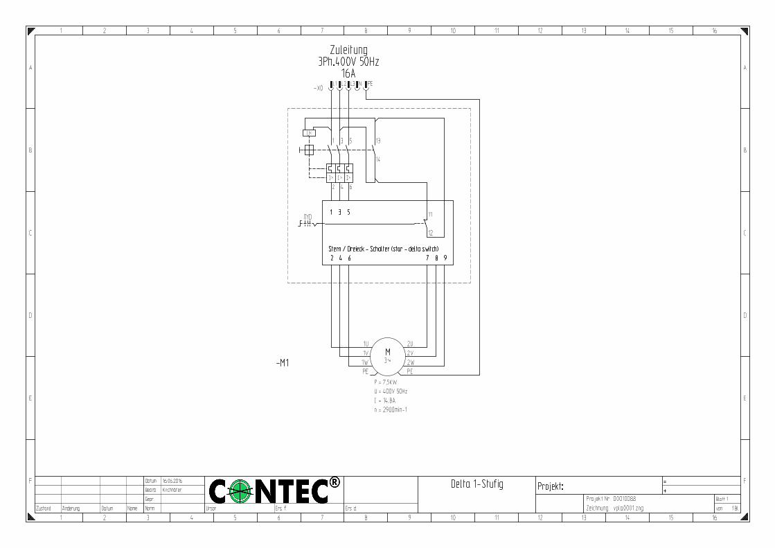
If you start the machine with the grinding tools placed on the floor you may damage the discs and/or parts of the grinder. Starting DELTA II European version Turn the main switch (Appendix diagram No. 90, lower, red switch) to Position 1. The motor switch (Appendix diagram No. 90, upper, black switch) must be in position “0”. Now turn the motor switch to start the motor. If you have a double speed version turn the motor switch in position 1 (1000rpm) or in position 2 (2000rpm). If you have a single speed version turn the motor switch in the “Star” position, wait 5 seconds and turn then
Betriebsanleitung / Manual DELTA II - 9 -
© CONTEC® 2018 CONTEC Maschinenbau & Entwicklungstechnik GmbH Hauptstrasse 146, 57518 Alsdorf (Sieg) / Germany Tel: +49 (0) 2741 9344-0 Fax: +49 (0) 2741 9344-29
Version mit einer Drehzahl durch Schalten in die „Stern“ und dann nach 5 Sekunden Warten in die „Dreieck“ Position. Der Motor beginnt sich zu drehen. Stellen Sie sicher, dass sich das Ventilatorrad auf dem Motor in Pfeilrichtung dreht. Dreht sich der Motor in die falsche Richtung, schalten Sie den Schalter zurück auf die 0-Stellung. Ziehen Sie die Kupplung der Zuleitung vom Maschinenstecker (Anhang Skizze Pos 92) ab. Der Netzstecker ist als Phasenwender ausgelegt. Durch Einstecken und Drehen eines Schlitzschraubendrehers werden zwei Phasen gewendet, und der Motor wird in richtiger Drehrichtung anlaufen. Aktivieren Sie die Maschine erneut mittels des Hauptschalters und schalten Sie den Motorschalter erneut ein. Nachdem Sie die Werkzeuge langsam und vorsichtig mittels der Liftvorrichtung auf den Boden abgesenkt haben, können Sie mit Ihrer Arbeit beginnen.
in the “Delta” position. The motor begins to turn. Make sure that the ventilator on the topside of the motor is turning in the correct direction as indicated by the arrow. If the motor rotates in the wrong direction, turn the switch back to the “0” position. Disconnect the socket of the extension lead from the machine plug (Appendix diagram No. 92). The plug is a reverse plug which means two phases can be swapped by inserting a screw driver in between two of the pins and twisting them round to the opposite direction. This allows the motor to turn in the correct direction. Restart the machine again by turning the main switch in 1 position and turn the motor switch. Now lower the grinding tools slowly and carefully on to the floor using the lifting device. Grinding is now possible. Starting DELTA II US version Make sure the Star-Delta-Switch (Appendix diagram No. 225) is in the “0” position. Turn the motor switch (Appendix diagram No. 217) to position “ON”. Turn the “Star-Delta-Switch” in the “Star” position. The motor begins to turn. Make sure that the ventilator on the topside of the motor is turning in the correct direction as indicated by the arrow. If the motor rotates in the wrong direction, turn the switch back to the “0” position. Press the emergency STOP button (Appendix diagram No. 223) and disconnect the plug (Appendix diagram No. 219). The plug is a reverse plug which means two phases can be swapped by inserting a screw driver in between two of the pins and twisting them round to the opposite direction. This allows the motor to turn in the correct direction. Restart the machine again and turn the “Star-Delta-Switch” (Appendix diagram No. 225) to position “Star”. The motor begins to turn. Wait until the motor is on full speed and then turn to position “Delta”. Now lower the grinding tools slowly and carefully on to the floor using the lifting device. Grinding is now possible.
Betriebsanleitung / Manual DELTA II - 10 -
© CONTEC® 2018 CONTEC Maschinenbau & Entwicklungstechnik GmbH Hauptstrasse 146, 57518 Alsdorf (Sieg) / Germany Tel: +49 (0) 2741 9344-0 Fax: +49 (0) 2741 9344-29
6 Einstellung und Wartung
6 Adjustments and Maintenance
6.1 Liftvorrichtung Die Liftvorrichtung muss in Abhängigkeit vom Verschleiß und der Art der Werkzeuge nachgestellt werden. Die Maschine wird unter dem Motor mit Hilfe einer Schraube mit Kontermutter hochgehoben. Der Hub dieser Schraube beträgt ca. 5 cm. Verändern Sie den Abstand der Schraube zum Boden im Arbeitszustand der Schleifmaschine (nicht geliftet) auf rund 2 cm zum Boden. 6.2 Höhenverstellung der Hinterrad-schwinge Die Hinterradschwinge kann mittels zwei Verstellmöglichkeiten den unterschiedlichen Werkzeugen angepaßt werden. Die Schwinge ist an drei Punkten befestigt. Jeweils an zwei Punkten am eigentlichen Rahmen und am dritten Punkt an der Spindelmutter. Die Höheneinstellung der Maschine und damit die Anpassung an verschiedene Werkzeuge und deren Verschleißzustand erfolgt über das Handrad der Spindel. Durch Verdrehen des Rades erfolgt eine Anhebung oder Absenkung der Schleifmaschine im hinteren Bereich. Die Höheneinstellung ist korrekt, wenn die Motor in etwa Lotrecht zum Boden steht 6.3 Verschiebung der Hinterradachse und damit Regulierung der Last auf den Werkzeugen Unterschiedliche Böden und unterschiedliche Werkzeuge bedürfen unterschiedlicher Lasten auf den Schleifköpfen. Durch Verschieben der Hinterradachse kann diese Last verändert werden. Wird die Achse in der hinteren Position befestigt, hat man die größte Last auf den Werkzeugen, in der vorderen Stellung wird sie geringer. Die Hinterradachse kann nach lösen zweier Schrauben in die erforderliche Stellung
6.1 Lifting Device The Lifting device must be adjusted according to the type and individual wear and tear of the tools. The machine is lifted using a screw under the motor. The lift of the lifting device is approximately 5 cm. When the grinding tools are placed on the floor, the distance between the screw and the floor should be 2 cm. Adjust it by turning the screw in or out. 6.2 Height Adjustment of the Rear Wheel Wing The rear wheel wing can be adjusted in two different ways to accommodate the different tools. The wing is secured to three points. Two on the frame itself and the other one to the Spindle nut. The actual height adjustment - fine and standard settings - of the grinding discs can be achieved by turning the hand wheel of the spindle. By turning the wheel the height can be set lengthways. Therefore avoiding uneven wear on the discs. 6.3 Shifting the rear wheel axis and thereby regulating the load on the discs and tools. Different floors and different tools require different loads on the grinding discs. By shifting the rear wheel axis, this load can be altered. When the axis is fixed in the rear position, this allows the maximum load on the tools. The more forward position means less load. The rear wheel axis can be comfortably moved by loosening the two screws behind the rear wheels.
Betriebsanleitung / Manual DELTA II - 11 -
© CONTEC® 2018 CONTEC Maschinenbau & Entwicklungstechnik GmbH Hauptstrasse 146, 57518 Alsdorf (Sieg) / Germany Tel: +49 (0) 2741 9344-0 Fax: +49 (0) 2741 9344-29
gebracht werden. 6.4 Riemenspannung Lösen Sie die vier Befestigungsschrauben des Motors. Dafür müssen Sie im vorderen Bereich das Blech über dem Riementrieb entfernen und im hinteren Bereich das Blech hinter der Spindel. Mit Hilfe einer M10er Mutter am hinteren Ende des Riemenspannbleches (Anhang Skizze Pos 101) unter dem Motor können Sie die Spannung des Riemens verändern. Der Zahnriemen der DELTA II sollte auf halben Weg zwischen Umlenkrolle und Motorwelle einen halben Zentimeter hin und her gerückt werden können.
6.4 Belt tension Loosen the four fixing screws of the motor. To do this you must remove the front belt cover and the cover behind the Spindle. By turning an M10 Nut on the rear side of the belt tensioner (metal plate underneath the motor Appendix diagram No. 101) the tension of the belt can be adjusted. The tooth belt of the DELTA II should be able to move halve a centimetre forwards and backwards half way between the pulley and the motor shaft.
7 Wechsel der Werkzeuge
7 Changing of the tools
Achtung: Vor Wartungsarbeiten Motor zum Stillstand bringen und Netzstecker ziehen. Achtung: Werkzeuge können nach gebrauch sehr heiß sein.
- Maschine über die Hinterräder kippen
und umlegen. - Alle Werkzeugaufnahmen (Anhang
Werkzeuge Pos 11) werden mit drei Innensechskantschrauben auf der Halteplatte (Anhang Explosionszeich-nung Pos 67) gehalten.
- Durch Lösen der Schrauben können die Aufnahmen mit Werkzeugen abgenommen werden.
- Schleifwerkzeug abnehmen und für nächsten Einsatz auf Verschleiß überprüfen.
- Neues Werkzeug gemäß Anhang „Werkzeuge“ anbringen.
Attention: Before working on the grinder bring the motor to a total stand still and disconnect from the power supply. Attention: Tools can be hot after use.
- Tilt the machine onto the back wheels and rest it on the bar underneath the control panel.
- All brackets for segment plates (Appendix diagram No. 11) are secured to the tool brackets (Appendix diagram No. 67) by 3 Allen screws.
- By loosening the screws the discs can be removed.
- Check the grinding tool for wear or damage ready for the next application.
- Fix new tools according to the appendix „Tools“.
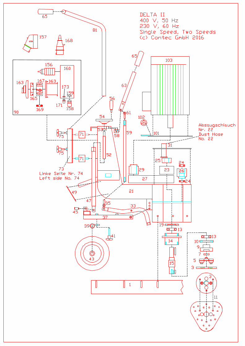
8 Anhang Explosionszeichnung (Skizze) / Diagrams Verdrahtungsplan / Wire diagram Teileliste / Part list
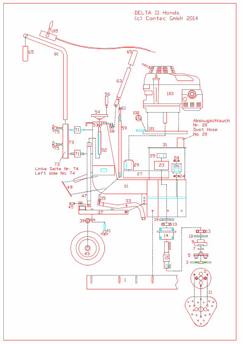
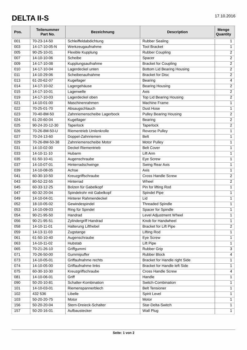
DELTA II-S 17.10.2016
Seite: 1 von 2
Pos.Teilenummer
Part No.Bezeichnung Description
MengeQuantity
001 70-23-14-50 Schleiffeldabdichtung Rubber Sealing 1
003 14-17-10-05-N Werkzeugaufnahme Tool Bracket 1
005 90-25-10-01 Flexible Kupplung Rubber Coupling 2
007 14-10-10-06 Scheibe Spacer 2
009 14-17-10-08 Kupplungsaufnahme Bracket for Coupling 2
010 14-17-10-04 Lagerdeckel unten Bottom Lid Bearing Housing 2
011 14-10-29-06 Scheibenaufnahme Bracket for Disc 2
013 61-20-62-07 Kugellager Bearing 4
014 14-17-10-02 Lagergehäuse Bearing Housing 2
015 14-17-10-01 Lagerwelle Axis 2
019 14-17-10-03 Lagerdeckel oben Top Lid Bearing Housing 2
021 14-10-01-00 Maschinenrahmen Machine Frame 1
022 70-25-01-70 Absaugschlauch Dust Hose 1
023 70-40-8M-50 Zahnriemenscheibe Lagerbock Pulley Bearing Housing 2
024 61-20-60-04 Kugellager Bearing 2
025 90-24-20-12-30 Taperlock Taperlock 2
026 70-26-8M-50-U Riementrieb Umlenkrolle Reverse Pulley 1
027 70-24-13-60 Doppel-Zahnriemen Belt 1
029 70-26-8M-50-38 Zahnriemenscheibe Motor Motor Pulley 1
031 14-10-02-00 Deckel Riementrieb Belt Cover 1
033 14-10-11-10 Hubarm Lift Arm 1
035 61-50-10-41 Augenschraube Eye Screw 1
037 14-10-07-01 Hinterradschwinge Swing Rear Axis 1
039 14-10-08-05 Achse Axis 1
041 60-30-10-50 Kreuzgriffschraube Cross Handle Screw 2
043 80-52-22-55 Hinterrad Wheel 2
045 60-33-12-25 Bolzen für Gabelkopf Pin for lifting Rod 1
047 60-32-20-04 Spindelrohr mit Gabelkopf Spindel Pipe 1
049 14-10-04-01 Hinterer Rahmendeckel Lid 1
052 18-10-05-02 Gewindespindel Threaded Spindle 1
053 14-10-09-03 Ring für Spindel Spacer for Spindle 1
054 90-21-95-50 Handrad Level Adjustment Wheel 1
056 90-21-95-51 Zylindergriff Handrad Knob for Handwheel 1
058 14-10-11-01 Halterung Lifthebel Bracket for Lift Pipe 2
059 14-13-11-03 Zugstange Lifting Rod 1
061 61-50-10-40 Augenschraube Eye Screw 1
063 14-10-11-02 Hubstab Lift Pipe 1
065 70-21-26-10 Griffgummi Rubber Grip 3
071 70-26-50-00 Gummipuffer Rubber Block 4
073 14-10-05-01 Griffaufnahme rechts Bracket for Handle right Side 1
074 14-10-05-00 Griffaufnahme links Bracket for Handle left Side 1
075 60-30-10-30 Kreuzgriffschraube Cross Handle Screw 4
081 14-10-06-01 Griff Handle 1
090 50-20-10-81 Schalter-Kombination Switch-Combination 1
101 14-10-03-01 Riemenspannerblech Belt Tensioner 1
102 432 536 Libelle Spirit Level 1
103 50-20-20-75 Motor Motor 1
156 50-20-20-04 Stern-Dreieck-Schalter Star-Delta-Switch 1
157 50-20-16-01 Aufbaustecker Wall Plug 1
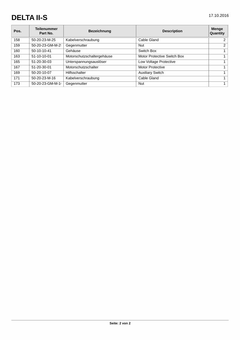
DELTA II-S 17.10.2016
Seite: 2 von 2
Pos.Teilenummer
Part No.Bezeichnung Description
MengeQuantity
158 50-20-23-M-25 Kabelverschraubung Cable Gland 2
159 50-20-23-GM-M-25 Gegenmutter Nut 2
160 50-10-10-41 Gehäuse Switch Box 1
163 51-10-10-01 Motorschutzschaltergehäuse Motor Protective Switch Box 1
165 51-20-30-03 Unterspannungsauslöser Low Voltage Protective 1
167 51-20-30-01 Motorschutzschalter Motor Protective 1
169 50-20-10-07 Hilfsschalter Auxiliary Switch 1
171 50-20-23-M-16 Kabelverschraubung Cable Gland 1
173 50-20-23-GM-M-16 Gegenmutter Nut 1
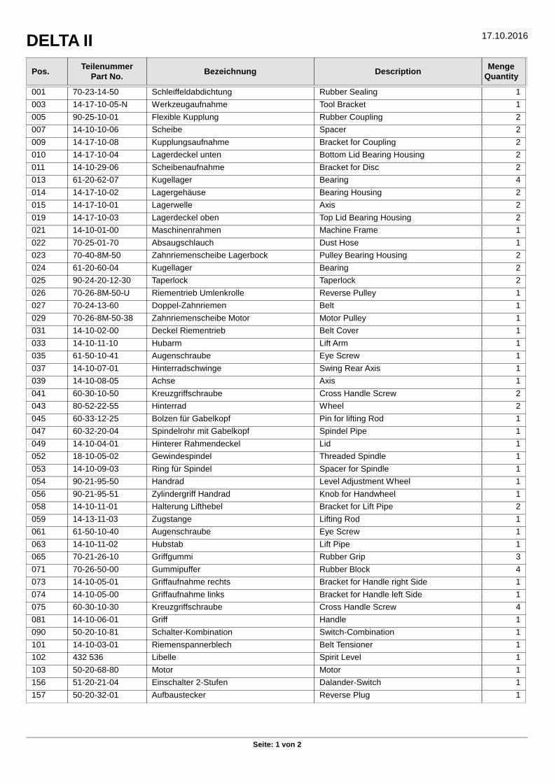
DELTA II 17.10.2016
Seite: 1 von 2
Pos.Teilenummer
Part No.Bezeichnung Description
MengeQuantity
001 70-23-14-50 Schleiffeldabdichtung Rubber Sealing 1
003 14-17-10-05-N Werkzeugaufnahme Tool Bracket 1
005 90-25-10-01 Flexible Kupplung Rubber Coupling 2
007 14-10-10-06 Scheibe Spacer 2
009 14-17-10-08 Kupplungsaufnahme Bracket for Coupling 2
010 14-17-10-04 Lagerdeckel unten Bottom Lid Bearing Housing 2
011 14-10-29-06 Scheibenaufnahme Bracket for Disc 2
013 61-20-62-07 Kugellager Bearing 4
014 14-17-10-02 Lagergehäuse Bearing Housing 2
015 14-17-10-01 Lagerwelle Axis 2
019 14-17-10-03 Lagerdeckel oben Top Lid Bearing Housing 2
021 14-10-01-00 Maschinenrahmen Machine Frame 1
022 70-25-01-70 Absaugschlauch Dust Hose 1
023 70-40-8M-50 Zahnriemenscheibe Lagerbock Pulley Bearing Housing 2
024 61-20-60-04 Kugellager Bearing 2
025 90-24-20-12-30 Taperlock Taperlock 2
026 70-26-8M-50-U Riementrieb Umlenkrolle Reverse Pulley 1
027 70-24-13-60 Doppel-Zahnriemen Belt 1
029 70-26-8M-50-38 Zahnriemenscheibe Motor Motor Pulley 1
031 14-10-02-00 Deckel Riementrieb Belt Cover 1
033 14-10-11-10 Hubarm Lift Arm 1
035 61-50-10-41 Augenschraube Eye Screw 1
037 14-10-07-01 Hinterradschwinge Swing Rear Axis 1
039 14-10-08-05 Achse Axis 1
041 60-30-10-50 Kreuzgriffschraube Cross Handle Screw 2
043 80-52-22-55 Hinterrad Wheel 2
045 60-33-12-25 Bolzen für Gabelkopf Pin for lifting Rod 1
047 60-32-20-04 Spindelrohr mit Gabelkopf Spindel Pipe 1
049 14-10-04-01 Hinterer Rahmendeckel Lid 1
052 18-10-05-02 Gewindespindel Threaded Spindle 1
053 14-10-09-03 Ring für Spindel Spacer for Spindle 1
054 90-21-95-50 Handrad Level Adjustment Wheel 1
056 90-21-95-51 Zylindergriff Handrad Knob for Handwheel 1
058 14-10-11-01 Halterung Lifthebel Bracket for Lift Pipe 2
059 14-13-11-03 Zugstange Lifting Rod 1
061 61-50-10-40 Augenschraube Eye Screw 1
063 14-10-11-02 Hubstab Lift Pipe 1
065 70-21-26-10 Griffgummi Rubber Grip 3
071 70-26-50-00 Gummipuffer Rubber Block 4
073 14-10-05-01 Griffaufnahme rechts Bracket for Handle right Side 1
074 14-10-05-00 Griffaufnahme links Bracket for Handle left Side 1
075 60-30-10-30 Kreuzgriffschraube Cross Handle Screw 4
081 14-10-06-01 Griff Handle 1
090 50-20-10-81 Schalter-Kombination Switch-Combination 1
101 14-10-03-01 Riemenspannerblech Belt Tensioner 1
102 432 536 Libelle Spirit Level 1
103 50-20-68-80 Motor Motor 1
156 51-20-21-04 Einschalter 2-Stufen Dalander-Switch 1
157 50-20-32-01 Aufbaustecker Reverse Plug 1

DELTA II 17.10.2016
Seite: 2 von 2
Pos.Teilenummer
Part No.Bezeichnung Description
MengeQuantity
158 50-20-23-M-25 Kabelverschraubung Cable Gland 2
159 50-20-23-GM-M-25 Gegenmutter Nut 2
160 50-10-10-41 Gehäuse Switch Box 1
163 51-10-10-01 Motorschutzschaltergehäuse Motor Protective Switch Box 1
165 51-20-30-03 Unterspannungsauslöser Low Voltage Protective 1
167 51-10-0-20-US Motorschutzschalter Motor Protective 1
171 50-20-23-M-16 Kabelverschraubung Cable Gland 1
173 50-20-23-GM-M-16 Gegenmutter Nut 1
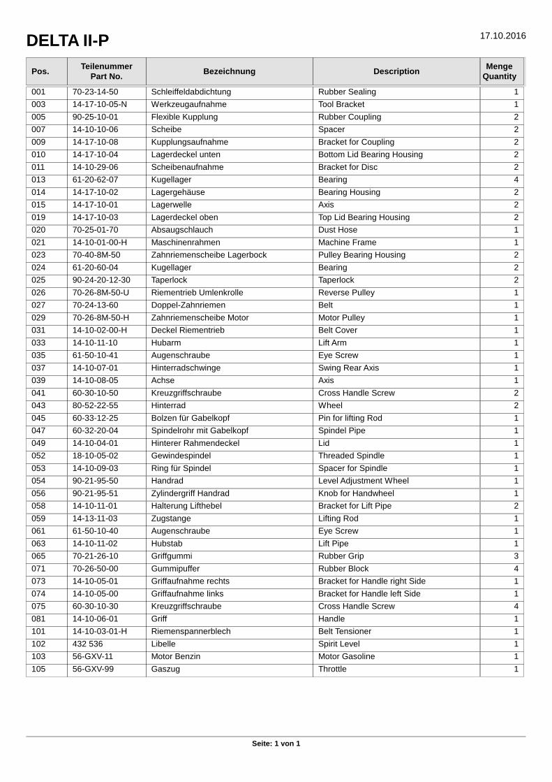
DELTA II-P 17.10.2016
Seite: 1 von 1
Pos.Teilenummer
Part No.Bezeichnung Description
MengeQuantity
001 70-23-14-50 Schleiffeldabdichtung Rubber Sealing 1
003 14-17-10-05-N Werkzeugaufnahme Tool Bracket 1
005 90-25-10-01 Flexible Kupplung Rubber Coupling 2
007 14-10-10-06 Scheibe Spacer 2
009 14-17-10-08 Kupplungsaufnahme Bracket for Coupling 2
010 14-17-10-04 Lagerdeckel unten Bottom Lid Bearing Housing 2
011 14-10-29-06 Scheibenaufnahme Bracket for Disc 2
013 61-20-62-07 Kugellager Bearing 4
014 14-17-10-02 Lagergehäuse Bearing Housing 2
015 14-17-10-01 Lagerwelle Axis 2
019 14-17-10-03 Lagerdeckel oben Top Lid Bearing Housing 2
020 70-25-01-70 Absaugschlauch Dust Hose 1
021 14-10-01-00-H Maschinenrahmen Machine Frame 1
023 70-40-8M-50 Zahnriemenscheibe Lagerbock Pulley Bearing Housing 2
024 61-20-60-04 Kugellager Bearing 2
025 90-24-20-12-30 Taperlock Taperlock 2
026 70-26-8M-50-U Riementrieb Umlenkrolle Reverse Pulley 1
027 70-24-13-60 Doppel-Zahnriemen Belt 1
029 70-26-8M-50-H Zahnriemenscheibe Motor Motor Pulley 1
031 14-10-02-00-H Deckel Riementrieb Belt Cover 1
033 14-10-11-10 Hubarm Lift Arm 1
035 61-50-10-41 Augenschraube Eye Screw 1
037 14-10-07-01 Hinterradschwinge Swing Rear Axis 1
039 14-10-08-05 Achse Axis 1
041 60-30-10-50 Kreuzgriffschraube Cross Handle Screw 2
043 80-52-22-55 Hinterrad Wheel 2
045 60-33-12-25 Bolzen für Gabelkopf Pin for lifting Rod 1
047 60-32-20-04 Spindelrohr mit Gabelkopf Spindel Pipe 1
049 14-10-04-01 Hinterer Rahmendeckel Lid 1
052 18-10-05-02 Gewindespindel Threaded Spindle 1
053 14-10-09-03 Ring für Spindel Spacer for Spindle 1
054 90-21-95-50 Handrad Level Adjustment Wheel 1
056 90-21-95-51 Zylindergriff Handrad Knob for Handwheel 1
058 14-10-11-01 Halterung Lifthebel Bracket for Lift Pipe 2
059 14-13-11-03 Zugstange Lifting Rod 1
061 61-50-10-40 Augenschraube Eye Screw 1
063 14-10-11-02 Hubstab Lift Pipe 1
065 70-21-26-10 Griffgummi Rubber Grip 3
071 70-26-50-00 Gummipuffer Rubber Block 4
073 14-10-05-01 Griffaufnahme rechts Bracket for Handle right Side 1
074 14-10-05-00 Griffaufnahme links Bracket for Handle left Side 1
075 60-30-10-30 Kreuzgriffschraube Cross Handle Screw 4
081 14-10-06-01 Griff Handle 1
101 14-10-03-01-H Riemenspannerblech Belt Tensioner 1
102 432 536 Libelle Spirit Level 1
103 56-GXV-11 Motor Benzin Motor Gasoline 1
105 56-GXV-99 Gaszug Throttle 1


![Axialkolbenpumpenc1940652.r52.cf0.rackcdn.com/5624fa39b8d39a7a410001eb/Katalog-PVplus... · 028 Nennleist. [kW] bei 1500 min-1 Nenn-Dreh- moment B 3 kW 20 Nm C 4 kW 25 Nm D 5,5 kW](https://static.fdokument.com/doc/165x107/5ffc2798ff04f17a481bde4b/axialkolbenpumpenc1940652r52cf0-028-nennleist-kw-bei-1500-min-1-nenn-dreh-.jpg)