Brillantes Fernsehen -...
17
Seaman 37 Seaman 45 GPS/Auto Skew Seaman 60 GPS/Auto Skew Benutzerhandbuch und Installationsanleitung Deutsch
Transcript of Brillantes Fernsehen -...
Seaman 37Seaman 45 GPS/Auto SkewSeaman 60 GPS/Auto Skew
Benutzerhandbuch und Installationsanleitung
Deutsch
Brillantes Fernsehen
DEUTSCH DEUTSCH
Inhaltsverzeichnis
02 03
Megasat Werke GmbH | Industriestraße 4a | D-97618 Niederlauer | www.megasat.tv | [email protected]
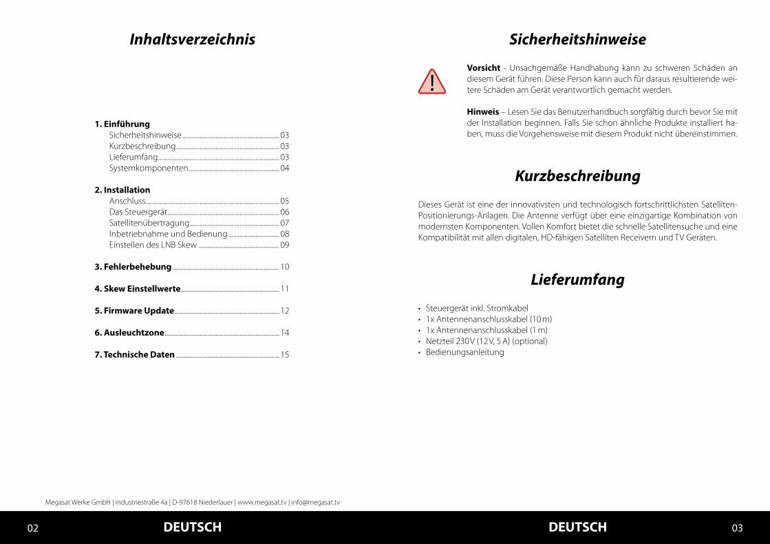
1. Einführung Sicherheitshinweise ............................................................. 03 Kurzbeschreibung ................................................................. 03 Lieferumfang ............................................................................ 03 Systemkomponenten ......................................................... 04
2. Installation Anschluss .................................................................................... 05 Das Steuergerät ...................................................................... 06 Satellitenübertragung ........................................................ 07 Inbetriebnahme und Bedienung ................................ 08 Einstellen des LNB Skew ................................................... 09
3. Fehlerbehebung ................................................................... 10
4. Skew Einstellwerte .............................................................. 11
5. Firmware Update .................................................................. 12
6. Ausleuchtzone ........................................................................ 14
7. Technische Daten ................................................................. 15
Sicherheitshinweise
Vorsicht - Unsachgemäße Handhabung kann zu schweren Schäden an diesem Gerät führen. Diese Person kann auch für daraus resultierende wei-tere Schäden am Gerät verantwortlich gemacht werden.
Hinweis – Lesen Sie das Benutzerhandbuch sorgfältig durch bevor Sie mit der Installation beginnen. Falls Sie schon ähnliche Produkte installiert ha-ben, muss die Vorgehensweise mit diesem Produkt nicht übereinstimmen.
Kurzbeschreibung
Lieferumfang
Dieses Gerät ist eine der innovativsten und technologisch fortschrittlichsten Satelliten-Positionierungs-Anlagen. Die Antenne verfügt über eine einzigartige Kombination von modernsten Komponenten. Vollen Komfort bietet die schnelle Satellitensuche und eine Kompatibilität mit allen digitalen, HD-fähigen Satelliten Receivern und TV Geräten.
• Steuergerät inkl. Stromkabel• 1x Antennenanschlusskabel (10 m)• 1x Antennenanschlusskabel (1 m)• Netzteil 230 V (12 V, 5 A) (optional)• Bedienungsanleitung
DEUTSCH DEUTSCH04 05
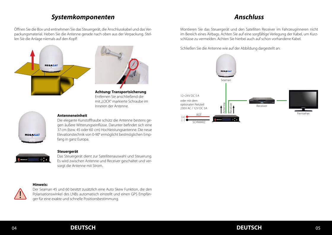
Systemkomponenten
AntenneneinheitDie elegante Kunstoffhaube schütz die Antenne bestens ge-gen äußere Witterungseinflüsse. Darunter befindet sich eine 37 cm (bzw. 45 oder 60 cm) Hochleistungsantenne. Die neue Elevationstechnik von 0-90° ermöglicht bestmöglichen Emp-fang in ganz Europa.
SteuergerätDas Steuergerät dient zur Satellitenauswahl und Steuerung. Es wird zwischen Antenne und Receiver geschaltet und ver-sorgt die Antenne mit Strom.
Hinweis:Der Seaman 45 und 60 besitzt zusätzlich eine Auto Skew Funktion, die den Polarisationswinkel des LNBs automatisch einstellt und einen GPS Empfän-ger für eine exakte und schnelle Positionsbestimmung.
Öffnen Sie die Box und entnehmen Sie das Steuergerät, die Anschlusskabel und das Ver-packungsmaterial. Heben Sie die Antenne gerade nach oben aus der Verpackung. Stel-len Sie die Anlage niemals auf den Kopf!
Achtung: TransportsicherungEntfernen Sie anschließend die mit „LOCK“ markierte Schraube im Inneren der Antenne.
Anschluss
Montieren Sie das Steuergerät und den Satelliten Receiver im Fahrzeuginneren nicht im Bereich eines Airbags. Achten Sie auf eine sorgfältige Verlegung der Kabel, um Kurz-schlüsse zu vermeiden. Achten Sie hierbei auch auf schon vorhandene Kabel.
Schließen Sie die Antenne wie auf der Abbildung dargestellt an:
Seaman
12~24 V DC 5 A
Ant
enna
Rece
iver
oder mit demoptionalen Netzteil230 V AC / 12 V DC 5A
Fernseher
Receiver
ROT
SCHWARZ( - )(+)
DEUTSCH DEUTSCH06 07
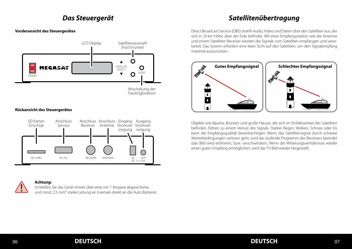
SatellitenübertragungDas Steuergerät
Gutes Empfangssignal Schlechtes Empfangssignal
Direct Broadcast Service (DBS) strahlt Audio, Video und Daten über den Satelliten aus, der sich in 35 km Höhe über der Erde befindet. Mit einer Empfangsstation wie die Antenne und einem Satelliten Receiver werden die Signale vom Satelliten empfangen und verar-beitet. Das System erfordert eine klare Sicht auf den Satelliten, um den Signalempfang maximal auszunutzen.
Objekte wie Bäume, Brücken und große Häuser, die sich im Einfallswinkel des Satelliten befinden, führen zu einem Verlust des Signals. Starker Regen, Wolken, Schnee oder Eis kann die Empfangsqualität beeinträchtigen. Wenn das Satellitensignal durch schwere Wetterbedingungen verloren geht, wird das laufende Programm des Receivers beendet (das Bild wird einfrieren, bzw. verschwinden). Wenn die Witterungsverhältnisse wieder einen guten Empfang ermöglichen, wird das TV Bild wieder hergestellt.
Achtung:Schließen Sie das Gerät immer über eine mit 7 Ampere abgesicherte,und mind. 2,5 mm² starke Leitung an (niemals direkt an die Auto Batterie).
EingangStromver-sorgung
AusgangStromver-sorgung
AnschlussAntenne
AnschlussReceiver
AnschlussService
SD KartenEinschub
Rückansicht des Steuergerätes
Vorderansicht des Steuergerätes
RS-232SD CARD RECEIVER ANTENNA INDC 12~24 V
OUT
Satellitenauswahl(hoch/runter)
Abschaltung derTrackingfunktion
SATELLITESELECT
SLEEP
LCD Display
POWER
OFF
ON
DEUTSCH DEUTSCH08 09
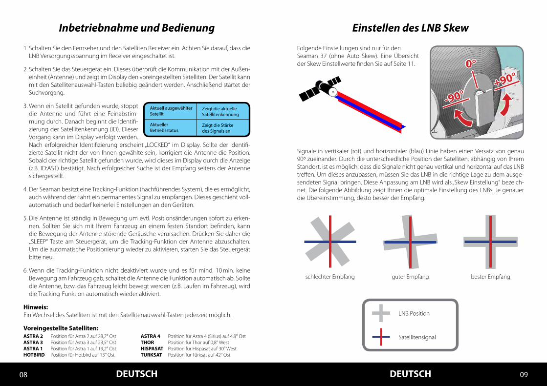
Inbetriebnahme und Bedienung
1. Schalten Sie den Fernseher und den Satelliten Receiver ein. Achten Sie darauf, dass die LNB Versorgungsspannung im Receiver eingeschaltet ist.
2. Schalten Sie das Steuergerät ein. Dieses überprüft die Kommunikation mit der Außen-einheit (Antenne) und zeigt im Display den voreingestellten Satelliten. Der Satellit kann mit den Satellitenauswahl-Tasten beliebig geändert werden. Anschließend startet der Suchvorgang.
3. Wenn ein Satellit gefunden wurde, stoppt die Antenne und führt eine Feinabstim-mung durch. Danach beginnt die Identifi-zierung der Satellitenkennung (ID). Dieser Vorgang kann im Display verfolgt werden. Nach erfolgreicher Identifizierung erscheint „LOCKED“ im Display. Sollte der identifi-zierte Satellit nicht der von Ihnen gewählte sein, korrigiert die Antenne die Position. Sobald der richtige Satellit gefunden wurde, wird dieses im Display durch die Anzeige (z.B. ID:AS1) bestätigt. Nach erfolgreicher Suche ist der Empfang seitens der Antenne sichergestellt.
4. Der Seaman besitzt eine Tracking-Funktion (nachführendes System), die es ermöglicht, auch während der Fahrt ein permanentes Signal zu empfangen. Dieses geschieht voll-automatisch und bedarf keinerlei Einstellungen an den Geräten.
5. Die Antenne ist ständig in Bewegung um evtl. Positionsänderungen sofort zu erken-nen. Sollten Sie sich mit Ihrem Fahrzeug an einem festen Standort befinden, kann die Bewegung der Antenne störende Geräusche verursachen. Drücken Sie daher die „SLEEP“ Taste am Steuergerät, um die Tracking-Funktion der Antenne abzuschalten. Um die automatische Positionierung wieder zu aktivieren, starten Sie das Steuergerät bitte neu.
6. Wenn die Tracking-Funktion nicht deaktiviert wurde und es für mind. 10 min. keine Bewegung am Fahrzeug gab, schaltet die Antenne die Funktion automatisch ab. Sollte die Antenne, bzw. das Fahrzeug leicht bewegt werden (z.B. Laufen im Fahrzeug), wird die Tracking-Funktion automatisch wieder aktiviert.
Hinweis: Ein Wechsel des Satelliten ist mit den Satellitenauswahl-Tasten jederzeit möglich.
Voreingestellte Satelliten:ASTRA 2 Position für Astra 2 auf 28,2° OstASTRA 3 Position für Astra 3 auf 23,5° OstASTRA 1 Position für Astra 1 auf 19,2° OstHOTBIRD Position für Hotbird auf 13° Ost
ASTRA 4 Position für Astra 4 (Sirius) auf 4,8° OstTHOR Position für Thor auf 0,8° WestHISPASAT Position für Hispasat auf 30° WestTURKSAT Position für Türksat auf 42° Ost
Einstellen des LNB Skew
Signale in vertikaler (rot) und horizontaler (blau) Linie haben einen Versatz von genau 90º zueinander. Durch die unterschiedliche Position der Satelliten, abhängig von Ihrem Standort, ist es möglich, dass die Signale nicht genau vertikal und horizontal auf das LNB treffen. Um dieses anzupassen, müssen Sie das LNB in die richtige Lage zu dem ausge-sendeten Signal bringen. Diese Anpassung am LNB wird als „Skew Einstellung“ bezeich-net. Die folgende Abbildung zeigt Ihnen die optimale Einstellung des LNBs. Je genauer die Übereinstimmung, desto besser der Empfang.
LNB Position
schlechter Empfang guter Empfang bester Empfang
Satellitensignal
0°
+90°
-90°
Folgende Einstellungen sind nur für denSeaman 37 (ohne Auto Skew). Eine Übersicht der Skew Einstellwerte finden Sie auf Seite 11.
DEUTSCH DEUTSCH10 11
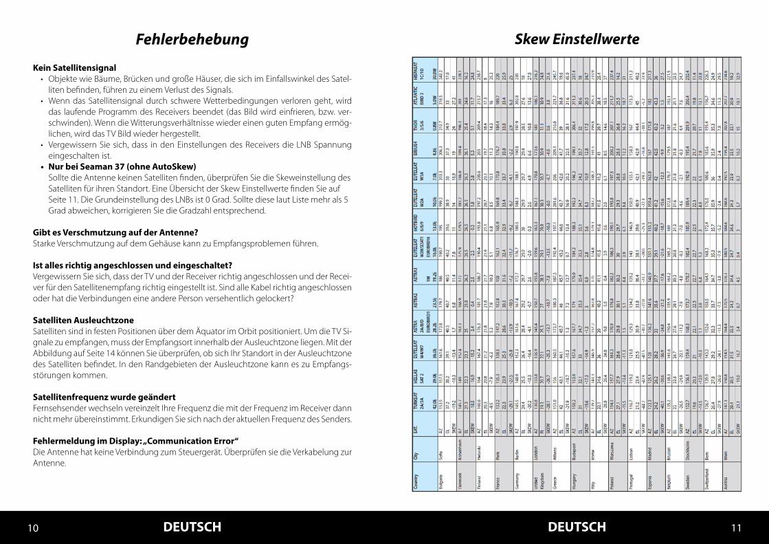
Skew EinstellwerteFehlerbehebung
Kein Satellitensignal• Objekte wie Bäume, Brücken und große Häuser, die sich im Einfallswinkel des Satel-
liten befinden, führen zu einem Verlust des Signals.• Wenn das Satellitensignal durch schwere Wetterbedingungen verloren geht, wird
das laufende Programm des Receivers beendet (das Bild wird einfrieren, bzw. ver-schwinden). Wenn die Witterungsverhältnisse wieder einen guten Empfang ermög-lichen, wird das TV Bild wieder hergestellt.
• Vergewissern Sie sich, dass in den Einstellungen des Receivers die LNB Spannung eingeschalten ist.
• Nur bei Seaman 37 (ohne AutoSkew) Sollte die Antenne keinen Satelliten finden, überprüfen Sie die Skeweinstellung des Satelliten für ihren Standort. Eine Übersicht der Skew Einstellwerte finden Sie auf Seite 11. Die Grundeinstellung des LNBs ist 0 Grad. Sollte diese laut Liste mehr als 5 Grad abweichen, korrigieren Sie die Gradzahl entsprechend.
Gibt es Verschmutzung auf der Antenne?Starke Verschmutzung auf dem Gehäuse kann zu Empfangsproblemen führen.
Ist alles richtig angeschlossen und eingeschaltet?Vergewissern Sie sich, dass der TV und der Receiver richtig angeschlossen und der Recei-ver für den Satellitenempfang richtig eingestellt ist. Sind alle Kabel richtig angeschlossen oder hat die Verbindungen eine andere Person versehentlich gelockert?
Satelliten AusleuchtzoneSatelliten sind in festen Positionen über dem Äquator im Orbit positioniert. Um die TV Si-gnale zu empfangen, muss der Empfangsort innerhalb der Ausleuchtzone liegen. Mit der Abbildung auf Seite 14 können Sie überprüfen, ob sich Ihr Standort in der Ausleuchtzone des Satelliten befindet. In den Randgebieten der Ausleuchtzone kann es zu Empfangs-störungen kommen.
Satellitenfrequenz wurde geändertFernsehsender wechseln vereinzelt Ihre Frequenz die mit der Frequenz im Receiver dann nicht mehr übereinstimmt. Erkundigen Sie sich nach der aktuellen Frequenz des Senders.
Fehlermeldung im Display: „Communication Error“Die Antenne hat keine Verbindung zum Steuergerät. Überprüfen sie die Verkabelung zur Antenne.
DEUTSCH DEUTSCH12 13
Firmware Update
Wenn die Frequenz, auf der die Antenne den Satelliten idendifiziert, abgeschaltet wird, muss ein Firmwareupdate des Steuergerätes durchgeführt werden.
Die aktuelle Firmware Version des Steuergerätes können Sie in den ersten 3 Sekunden nach dem Einschalten im unteren Bereich des Displays ablesen.
Bitte erkundigen Sie sich auf unserer Homepage nach der aktuellsten Firmware Version.
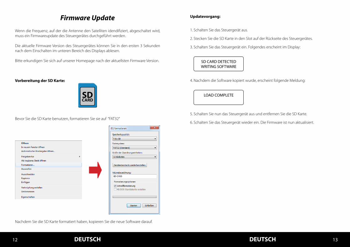
Vorbereitung der SD Karte:
Bevor Sie die SD Karte benutzen, formatieren Sie sie auf “FAT32“
Nachdem Sie die SD Karte formatiert haben, kopieren Sie die neue Software darauf.
Updatevorgang:
1. Schalten Sie das Steuergerät aus.
2. Stecken Sie die SD Karte in den Slot auf der Rückseite des Steuergerätes.
3. Schalten Sie das Steuergerät ein. Folgendes erscheint im Display:
4. Nachdem die Software kopiert wurde, erscheint folgende Meldung:
5. Schalten Sie nun das Steuergerät aus und entfernen Sie die SD Karte.
6. Schalten Sie das Steuergerät wieder ein. Die Firmware ist nun aktualisiert.
SD CARD DETECTEDWRITING SOFTWARE
LOAD COMPLETESDCARD

DEUTSCH DEUTSCH14 15
Konformitätserklärung
Technische Daten
Hinweis:Gewicht und Abmessungen sind nicht die absolut exakten Werte.Technische Details können jederzeit geändert werden (nach Hersteller) ohne vorherige Ankündigung.
Konformitätserklärung
Hiermit wird die Übereinstimmung mit folgenden Richtlinien/Normen bestätigt:Richtlinie zur elektromagnetischen Verträglichkeit 2004/108/EGEN 55013: 2001 + A1: 2003 + A2: 2006EN 55020: 2007EN 61000-3-2:2006 + A1:2009 + A2:2009EN 61000-3-3:2008Niederspannungsrichtlinie 2006/95/EGEN 60065: 2002 + A1: 2006 + A11: 2008
Seaman 37 Seaman 37 Seaman 45 Seaman 60Seaman 45 GPS/AutoSkew
Seaman 60 GPS/AutoSkew
Antennen Typ ....................................................Off-Set-Spiegel ...................... Off-Set-Spiegel ......................Off-Set-Spiegel
Anzahl der Teilnehmer .................................3 ...................................................... 3 ...................................................... 3
LNB Typ ..................................................................Universal LNB .......................... Universal LNB ..........................Universal LNB
Frequenzband ..................................................Ku Band ...................................... Ku Band ...................................... Ku Band
Frequenzbereich .............................................10.7 GHz bis 12.75 GHz ...... 10.7 GHz bis 12.75 GHz...... 10.7 GHz bis 12.75 GHz
LNB Verstärkung ...............................................31 dBi............................................ 33 dBi ........................................... 35 dBi
Empfangsleistung ...........................................51 dBW ........................................ 49 dBW ........................................ 47 dBW
Polarisation ..........................................................V/H oder RHCP/LHCP ........ V/H oder RHCP/LHCP ........ V/H oder RHCP/LHCP
Motorsteuerung ...............................................2-Achsen DC Motor ............ 2-Achsen DC Motor ............ 2-Achsen DC Motor
Neigungswinkel ...............................................0° bis 90° .................................... 0° bis 90° .................................... 0° bis 90°
Suchwinkel ..........................................................360° ............................................... 360° ............................................... 360°
Drehgeschwindigkeit....................................50° / Sek. .................................... 50° / Sek. .................................... 50° / Sek.
Ausrichtungszeit ..............................................1 - 2 min. ...................................... 1 - 2 min. ..................................... 1 - 2 min.
Temperaturbereich ......................................... -25° C bis +70° C .................... -25° C bis +70° C .................... -25° C bis +70° C
Spannungsversorgung ................................12 V DC @ 5 A ........................... 12 V DC @ 5 A ........................... 12 V DC @ 5 A
Gewicht .................................................................9 kg ............................................... 15 kg ............................................. 20 kg
Abmessungen Spiegel (Ø) .........................370 mm....................................... 450 mm ...................................... 600 mm
Abmessungen Gehäuse (Ø/H) ................440 x 430 mm ......................... 550 x 580 mm ......................... 800 x 800 mm
Abmessungen Steuergerät (B/H/T) .....245 x 43 x 147 mm............... 245 x 43 x 147 mm .............. 245 x 43 x 147 mm
Ausleuchtzone
Hinweis:In den Randgebieten der Ausleuchtzone kann es zu Empfangsstörungen kommen.
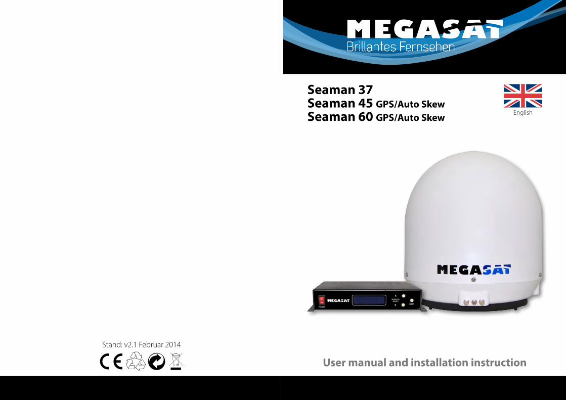
Stand: v2.1 Februar 2014
Seaman 37Seaman 45 GPS/Auto SkewSeaman 60 GPS/Auto Skew
User manual and installation instruction
English
Brillantes Fernsehen
Contents
1. Introduction Safety Information ................................................................ 03 Short description ................................................................... 03 Delivery ........................................................................................ 03 System Components .......................................................... 04
2. Installation Connection ............................................................................... 05 The control unit ...................................................................... 06 Satellite broadcasting ......................................................... 07 Startup and operation ........................................................ 08 Setting the LNB skew .......................................................... 09
3. Troubleshooting ................................................................... 10
4. Skew Settings .......................................................................... 11
5. Firmware Update .................................................................. 12
6. Footprint ..................................................................................... 14
7. Specifications .......................................................................... 15
ENGLISH ENGLISH02 03
Safety Information
Caution – Improper handling by unqualified personnel can cause serious damage to this equipment. Unqualified personnel who tamper with this equipment may be held liable for any resultant damage to the equipment.
Note – Before you begin, carefully read each of the procedures in this ma-nual. If you have not performed similar operations on comparable equip-ment, do not attempt to perform these procedures.
Short description
Delivery
The satellite antenna system is the innovative and a technologically advanced satellite Positioner system. The antenna has a unique combination of cutting-edge components. Fast satellite search and compatibility with all digital, HD-ready set-top boxes and TV sets are guaranteed.
• Control unit incl. powercable• 1x antenna cable (10 m)• 1x antenna cable (1 m)• Power supply 230 V (12 V, 5 A) (optional)• User manual
System Components
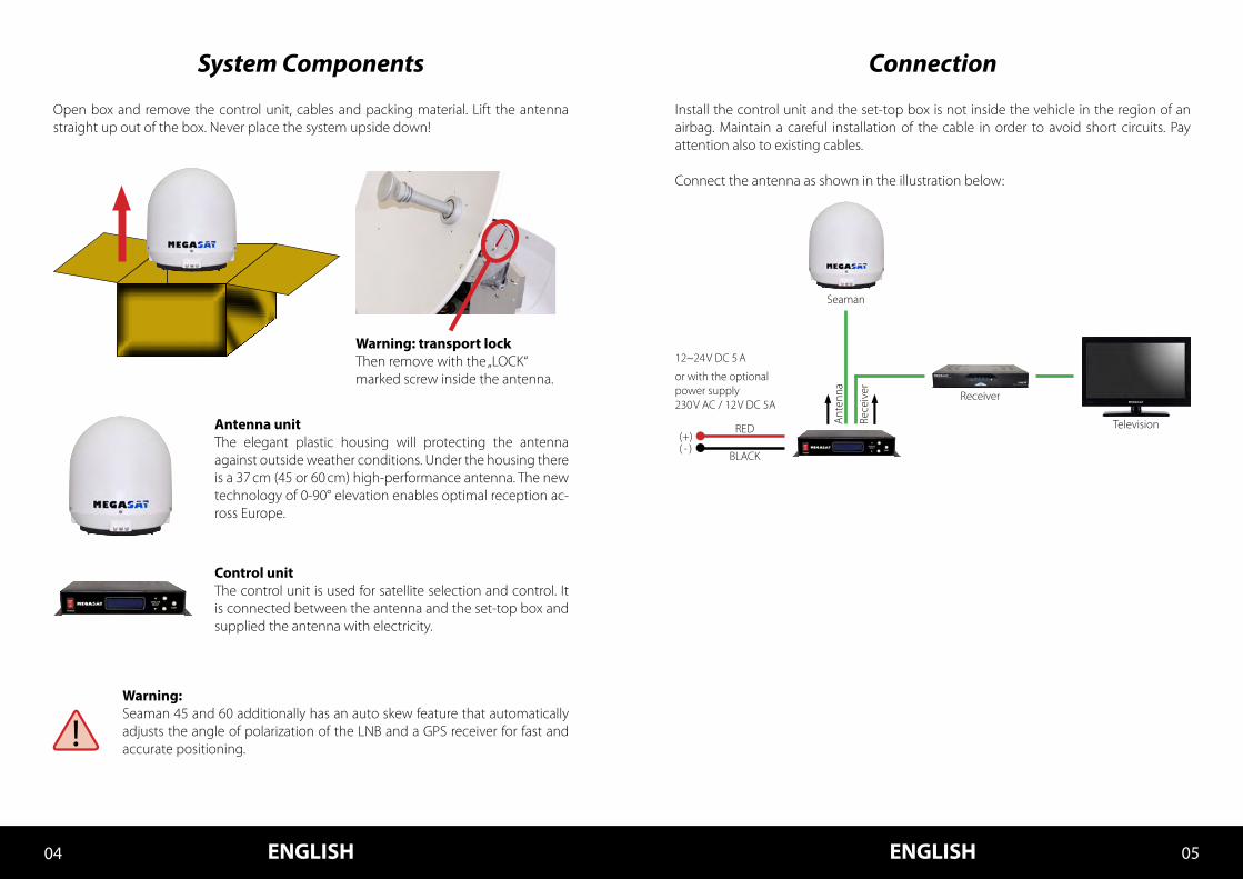
Antenna unitThe elegant plastic housing will protecting the antenna against outside weather conditions. Under the housing there is a 37 cm (45 or 60 cm) high-performance antenna. The new technology of 0-90° elevation enables optimal reception ac-ross Europe.
Control unitThe control unit is used for satellite selection and control. It is connected between the antenna and the set-top box and supplied the antenna with electricity.
Open box and remove the control unit, cables and packing material. Lift the antenna straight up out of the box. Never place the system upside down!
ENGLISH ENGLISH04 05
Warning:Seaman 45 and 60 additionally has an auto skew feature that automatically adjusts the angle of polarization of the LNB and a GPS receiver for fast and accurate positioning.
Warning: transport lockThen remove with the „LOCK“ marked screw inside the antenna.
Seaman
Connection
Install the control unit and the set-top box is not inside the vehicle in the region of an airbag. Maintain a careful installation of the cable in order to avoid short circuits. Pay attention also to existing cables.
Connect the antenna as shown in the illustration below:
12~24 V DC 5 A
Ant
enna
Rece
iver
or with the optional power supply230 V AC / 12 V DC 5A
Television
Receiver
RED
BLACK( - )(+)
Satellite broadcasting
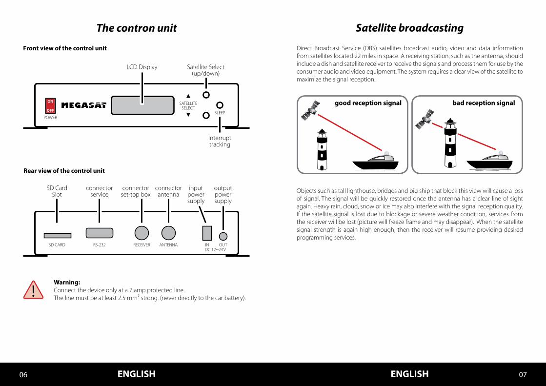
Direct Broadcast Service (DBS) satellites broadcast audio, video and data information from satellites located 22 miles in space. A receiving station, such as the antenna, should include a dish and satellite receiver to receive the signals and process them for use by the consumer audio and video equipment. The system requires a clear view of the satellite to maximize the signal reception.
Objects such as tall lighthouse, bridges and big ship that block this view will cause a loss of signal. The signal will be quickly restored once the antenna has a clear line of sight again. Heavy rain, cloud, snow or ice may also interfere with the signal reception quality. If the satellite signal is lost due to blockage or severe weather condition, services from the receiver will be lost (picture will freeze frame and may disappear). When the satellite signal strength is again high enough, then the receiver will resume providing desired programming services.
The contron unit
Warning:Connect the device only at a 7 amp protected line.The line must be at least 2.5 mm² strong. (never directly to the car battery).
Rear view of the control unit
Front view of the control unit
ENGLISH ENGLISH06 07
good reception signal bad reception signal
input power supply
output power supply
connectorantenna
connectorset-top box
connectorservice
SD Card Slot
RS-232SD CARD RECEIVER ANTENNA INDC 12~24 V
OUT
Satellite Select(up/down)
Interrupttracking
SATELLITESELECT
SLEEP
LCD Display
POWER
OFF
ON
Setting the LNB Skew
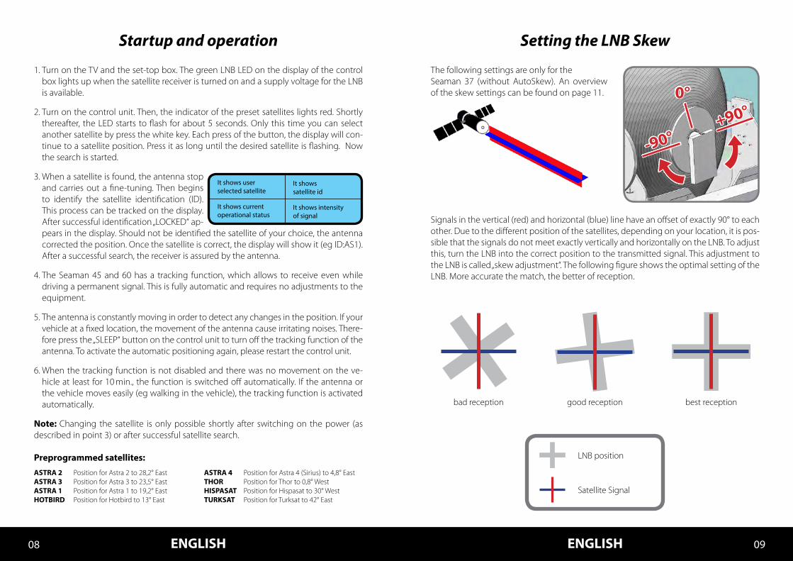
Signals in the vertical (red) and horizontal (blue) line have an offset of exactly 90° to each other. Due to the different position of the satellites, depending on your location, it is pos-sible that the signals do not meet exactly vertically and horizontally on the LNB. To adjust this, turn the LNB into the correct position to the transmitted signal. This adjustment to the LNB is called „skew adjustment“. The following figure shows the optimal setting of the LNB. More accurate the match, the better of reception.
LNB position
bad reception good reception best reception
Satellite Signal
Startup and operation
1. Turn on the TV and the set-top box. The green LNB LED on the display of the control box lights up when the satellite receiver is turned on and a supply voltage for the LNB is available.
2. Turn on the control unit. Then, the indicator of the preset satellites lights red. Shortly thereafter, the LED starts to flash for about 5 seconds. Only this time you can select another satellite by press the white key. Each press of the button, the display will con-tinue to a satellite position. Press it as long until the desired satellite is flashing. Now the search is started.
3. When a satellite is found, the antenna stop and carries out a fine-tuning. Then begins to identify the satellite identification (ID). This process can be tracked on the display. After successful identification „LOCKED“ ap-pears in the display. Should not be identified the satellite of your choice, the antenna corrected the position. Once the satellite is correct, the display will show it (eg ID:AS1). After a successful search, the receiver is assured by the antenna.
4. The Seaman 45 and 60 has a tracking function, which allows to receive even while driving a permanent signal. This is fully automatic and requires no adjustments to the equipment.
5. The antenna is constantly moving in order to detect any changes in the position. If your vehicle at a fixed location, the movement of the antenna cause irritating noises. There-fore press the „SLEEP“ button on the control unit to turn off the tracking function of the antenna. To activate the automatic positioning again, please restart the control unit.
6. When the tracking function is not disabled and there was no movement on the ve-hicle at least for 10 min., the function is switched off automatically. If the antenna or the vehicle moves easily (eg walking in the vehicle), the tracking function is activated automatically.
Note: Changing the satellite is only possible shortly after switching on the power (as described in point 3) or after successful satellite search.
Preprogrammed satellites:
ENGLISH ENGLISH08 09
The following settings are only for theSeaman 37 (without AutoSkew). An overview of the skew settings can be found on page 11.
ASTRA 2 Position for Astra 2 to 28,2° EastASTRA 3 Position for Astra 3 to 23,5° EastASTRA 1 Position for Astra 1 to 19,2° EastHOTBIRD Position for Hotbird to 13° East
ASTRA 4 Position for Astra 4 (Sirius) to 4,8° EastTHOR Position for Thor to 0,8° WestHISPASAT Position for Hispasat to 30° WestTURKSAT Position for Turksat to 42° East
0°
+90°
-90°
11
Troubleshooting
No Signal• Objects such as trees, bridges, and large buildings, which are located in the angle of
the satellite will lead to a loss of the signal.• If the satellite signal is lost through severe weather conditions, the current program
of the receiver is stopped (the image freeze, or disappear). If the weather conditions allow a good reception again, the TV screen will be restored.
• Make sure that the settings of the set-top box to LNB voltage is switched on. This is indicated by the green LED on the control unit (LED green = LNB voltage present).
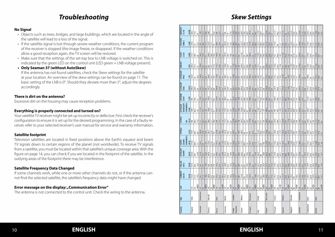
• Only Seaman 37 (without AutoSkew) If the antenna has not found satellites, check the Skew settings for the satellite at your location. An overview of the skew settings can be found on page 11. The basic setting of the LNB is 0°. Should they deviate more than 5°, adjust the degrees accordingly.
There is dirt on the antenna?Excessive dirt on the housing may cause reception problems.
Everything is properly connected and turned on?Your satellite TV receiver might be set up incorrectly or defective. First check the receiver’s configuration to ensure it is set up for the desired programming. In the case of a faulty re-ceiver, refer to your selected receiver’s user manual for service and warranty information.
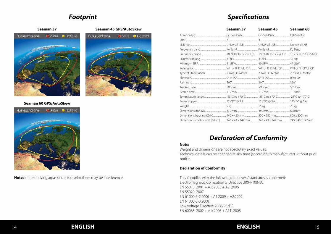
Satellite footprintTelevision satellites are located in fixed positions above the Earth’s equator and beam TV signals down to certain regions of the planet (not worldwide). To receive TV signals from a satellite, you must be located within that satellite’s unique coverage area. With the figure on page 14, you can check if you are located in the footprint of the satellite. In the outlying areas of the footprint there may be interference.
Satellite Frequency Data ChangedIf some channels work, while one or more other channels do not, or if the antenna can-not find the selected satellite, the satellite’s frequency data might have changed.
Error message on the display: „Communication Error“The antenna is not connected to the control unit. Check the wiring to the antenna.
Skew Settings
ENGLISH ENGLISH10 11
11ENGLISH ENGLISH12 13
Firmware Update
When the frequency is switched off, on which the antenna idendifiziert the satellite, you must update the firmware of the control unit.
The current firmware version of the control unit, you can read on the bottom of the screen in the first 3 seconds after switching on.
Please check our website for the latest firmware version.
Preparing the SD card:
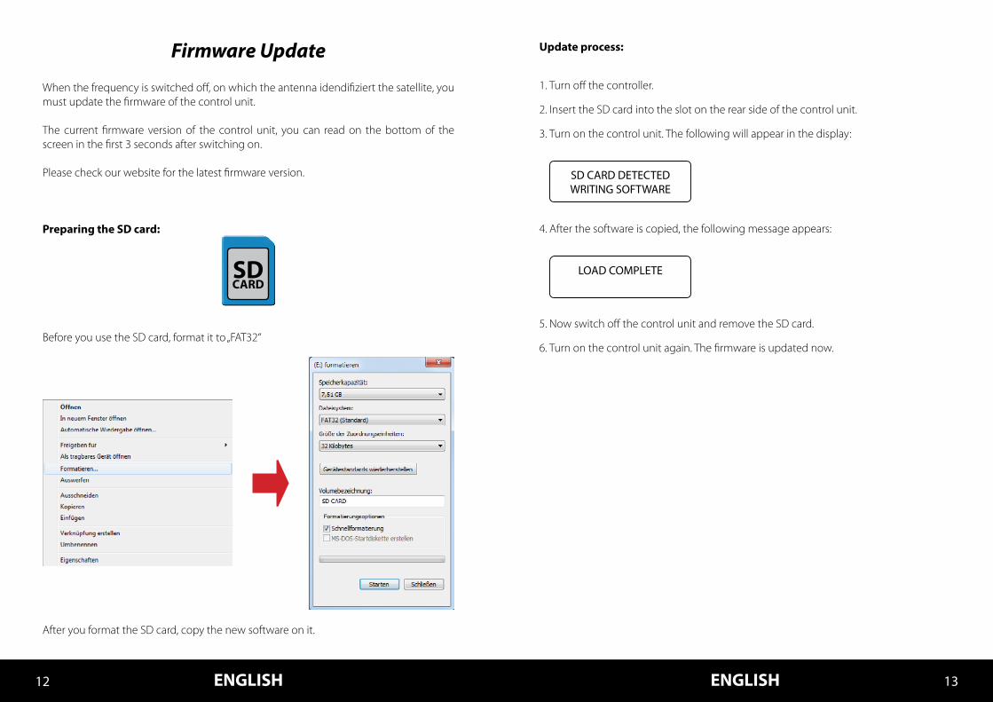
Before you use the SD card, format it to „FAT32“
After you format the SD card, copy the new software on it.
Update process:
1. Turn off the controller.
2. Insert the SD card into the slot on the rear side of the control unit.
3. Turn on the control unit. The following will appear in the display:
4. After the software is copied, the following message appears:
5. Now switch off the control unit and remove the SD card.
6. Turn on the control unit again. The firmware is updated now.
SD CARD DETECTEDWRITING SOFTWARE
LOAD COMPLETESDCARD
Declaration of Conformity
Specifications
Note:Weight and dimensions are not absolutely exact values .Technical details can be changed at any time (according to manufacturer) without prior notice.
Declaration of Conformity
This complies with the following directives / standards is confirmed:Electromagnetic Compatibility Directive 2004/108/ECEN 55013: 2001 + A1: 2003 + A2: 2006EN 55020: 2007EN 61000-3-2:2006 + A1:2009 + A2:2009EN 61000-3-3:2008Low Voltage Directive 2006/95/EGEN 60065: 2002 + A1: 2006 + A11: 2008
Footprint
Note: In the outlying areas of the footprint there may be interference.
11ENGLISH ENGLISH14 15
Seaman 37 Seaman 45 GPS/AutoSkew
Seaman 60 GPS/AutoSkew
Seaman 37 Seaman 45 Seaman 60Antenna typ ........................................................Off-Set-Dish ............................. Off-Set-Dish .............................Off-Set-Dish
Users ........................................................................3 ...................................................... 3 ...................................................... 3
LNB typ ...................................................................Universal LNB .......................... Universal LNB ..........................Universal LNB
Frequency band ..............................................Ku Band ...................................... Ku Band ...................................... Ku Band
Frequency range .............................................10.7 GHz to 12.75 GHz ....... 10.7 GHz to 12.75 GHz ....... 10.7 GHz to 12.75 GHz
LNB Verstärkung ...............................................31 dBi............................................ 33 dBi ........................................... 35 dBi
Minimum EIRP ...................................................51 dBW ........................................ 49 dBW ........................................ 47 dBW
Polarization ..........................................................V/H or RHCP/LHCP .............. V/H or RHCP/LHCP .............. V/H or RHCP/LHCP
Type of Stabilisation .......................................2-Axis DC Motor .................... 2-Axis DC Motor .................... 2-Axis DC Motor
Elevation................................................................0° to 90° ...................................... 0° to 90° ...................................... 0° to 90°
Azimuth .................................................................360° ............................................... 360° ............................................... 360°
Tracking rate .......................................................50° / sec. ..................................... 50° / sec. ..................................... 50° / sec.
Search time .........................................................1 - 2 min. ...................................... 1 - 2 min. ..................................... 1 - 2 min.
Temperature range ......................................... -25° C to +70° C ...................... -25° C to +70° C ...................... -25° C to +70° C
Power supply ......................................................12 V DC @ 5 A ........................... 12 V DC @ 5 A ........................... 12 V DC @ 5 A
Weight ....................................................................9 kg ............................................... 15 kg ............................................. 20 kg
Dimensions dish (Ø).......................................370 mm....................................... 450 mm ...................................... 600 mm
Dimensions housing (Ø/H) ........................440 x 430 mm ......................... 550 x 580 mm ......................... 800 x 800 mm
Dimensions control unit (B/H/T) ...........245 x 43 x 147 mm............... 245 x 43 x 147 mm .............. 245 x 43 x 147 mm

Status: v2.1 February 2014