Co-Rotating Twin-Screw Extruder - Carl Hanser...
9
Co-Rotating Twin-Screw Extruder Herausgegeben von Klemens Kohlgrüber ISBN-10: 3-446-41372-3 ISBN-13: 978-3-446-41372-6 Leseprobe Weitere Informationen oder Bestellungen unter http://www.hanser.de/978-3-446-41372-6 sowie im Buchhandel
Transcript of Co-Rotating Twin-Screw Extruder - Carl Hanser...

Co-Rotating Twin-ScrewExtruder
Herausgegeben von Klemens Kohlgrüber
ISBN-10: 3-446-41372-3ISBN-13: 978-3-446-41372-6
Leseprobe
Weitere Informationen oder Bestellungen unterhttp://www.hanser.de/978-3-446-41372-6
sowie im Buchhandel
Masterbatches11%
Compounds89%
65%
20%16%
31%
22%
18%
18%
Color compounds
PVC
Polyolefins
Engineeringthermoplastics
Polyolefins
EngineeringthermoplasticsPVC
Source 2
Source 1
Source 1
4 General Overview of the CompoundingProcess: Tasks, Selected Applications,and Process Zones
REINER RUDOLF
4.1 Compounding Tasks and Requirements
The properties of polymers need constant refinement in order to meet the constantlyincreasing demands on plastic parts. Since the development of new polymers is steadilydecreasing [1], deliberate modification of the properties of a base polymer by means ofadditives and/or blending with other polymers is becoming increasingly important. Hereinlies the primary task of compounding.
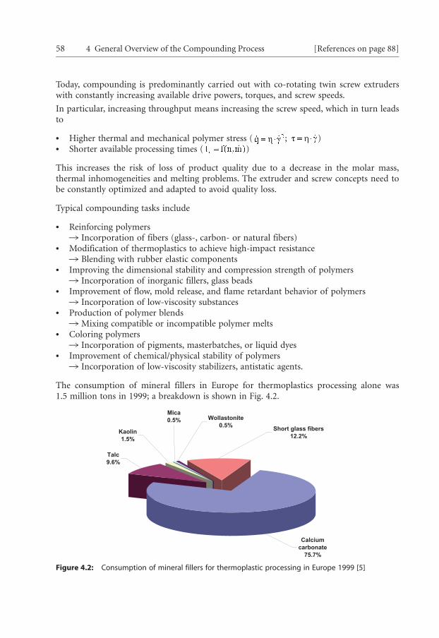
According to an AMI study [2], 6,000,000 tons of compounds and 750,000 tons ofmasterbatches were consumed in Western Europe in 2003. The Western Europeancompound and masterbatch market is shown in Fig. 4.1.
Figure 4.1: Compound and masterbatch market in Western Europe [3, 4]
The requirements of the compounding process are characterized by
> Increasing throughputs> Decreasing batch sizes> Increasing product variety> Increasing quality requirements,> Increasing filler contents> New products (e.g., nano-filler materials, modified and blended polymers)
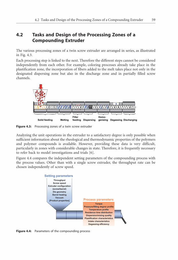
Calciumcarbonate
75.7%
Short glass fibers12.2%
Wollastonite0.5%
Talc9.6%
Kaolin1.5%
Mica0.5%
Today, compounding is predominantly carried out with co-rotating twin screw extruderswith constantly increasing available drive powers, torques, and screw speeds.
In particular, increasing throughput means increasing the screw speed, which in turn leadsto
> Higher thermal and mechanical polymer stress ( ; )> Shorter available processing times ( )
This increases the risk of loss of product quality due to a decrease in the molar mass,thermal inhomogeneities and melting problems. The extruder and screw concepts need tobe constantly optimized and adapted to avoid quality loss.
Typical compounding tasks include
> Reinforcing polymers1 Incorporation of fibers (glass-, carbon- or natural fibers)
> Modification of thermoplastics to achieve high-impact resistance1 Blending with rubber elastic components
> Improving the dimensional stability and compression strength of polymers1 Incorporation of inorganic fillers, glass beads
> Improvement of flow, mold release, and flame retardant behavior of polymers1 Incorporation of low-viscosity substances
> Production of polymer blends1 Mixing compatible or incompatible polymer melts
> Coloring polymers1 Incorporation of pigments, masterbatches, or liquid dyes
> Improvement of chemical/physical stability of polymers1 Incorporation of low-viscosity stabilizers, antistatic agents.
The consumption of mineral fillers in Europe for thermoplastics processing alone was1.5 million tons in 1999; a breakdown is shown in Fig. 4.2.
Figure 4.2: Consumption of mineral fillers for thermoplastic processing in Europe 1999 [5]
58 4 General Overview of the Compounding Process [References on page 88]
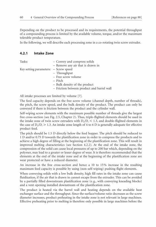
Solid feedingFillerfeedingMelting Dispersing
Homo-genizing Degassing Discharging
ThroughputScrew speed
Extruder configuration(screw/barrel)Die geometryBarrel heating
Vacuum[Product properties]
SettingSetting parametersparameters
TorquePressure/filling degree profile
Temperature profileResidence time distributionDispersion/mixing quality
Plastification characteristicsIntake characteristicsDegassing efficiency
ProcessProcess parametersparameters
4.2 Tasks and Design of the Processing Zones of aCompounding Extruder
The various processing zones of a twin screw extruder are arranged in series, as illustratedin Fig. 4.3.
Each processing step is linked to the next. Therefore the different steps cannot be consideredindependently from each other. For example, coloring processes already take place in theplastification zone, the incorporation of fibers added to the melt takes place not only in thedesignated dispersing zone but also in the discharge zone and in partially filled screwchannels.
Figure 4.3: Processing zones of a twin screw extruder
Analyzing the unit operations in the extruder to a satisfactory degree is only possible whensufficient information about the rheological and thermodynamic properties of the polymersand polymer compounds is available. However, providing these data is very difficult,particularly in zones with considerable changes in state. Therefore, it is frequently necessaryto refer back to model investigations and trials [6].
Figure 4.4 compares the independent setting parameters of the compounding process withthe process values. Other than with a single screw extruder, the throughput rate can bechosen independently of screw speed.
Figure 4.4: Parameters of the compounding process
4.2 Tasks and Design of the Processing Zones of a Compounding Extruder 59
Depending on the product to be processed and its requirements, the potential throughputof a compounding process is limited by the available volume, torque, and/or the maximumtolerable product temperature.
In the following, we will describe each processing zone in a co-rotating twin screw extruder.
4.2.1 Intake Zone
Tasks: – Convey and compress solids– Remove any air that is drawn in
Key setting parameters: – Screw speed– Throughput– Free screw volume– Pitch– Bulk density of the product– Friction between product and barrel wall
All intake processes are limited by volume [7].
The feed capacity depends on the free screw volume (channel depth, number of threads),the pitch, the screw speed, and the bulk density of the product. The product can only beconveyed if there is friction between the product and the cylinder wall.
Self-wiping screw elements with the maximum possible number of threads give the largestfree cross-section (see Fig. 2.5, Chapter 2). Thus, triple-flighted elements should be used inthe intake zone of twin screw extruders with Do/Di X 1.3, and double-flighted elements inthe case of Do/Di G 1.3. An intake zone length of 4 to 6 D is generally adequate for effectiveproduct feed.
The pitch should be 1.5 D directly below the feed hopper. The pitch should be reduced to1 D and/or 0.75 D towards the plastification zone in order to compress the products and toachieve a high degree of filling at the beginning of the plastification zone. This will result inimproved melting characteristics (see Section 4.2.2). At the end of the intake zone, thecompression of the solid can cause local pressures of up to 200 bar which, depending on thepolymer, may lead to a greater or lesser degree of wear. It is therefore recommended that theelements at the end of the intake zone and at the beginning of the plastification zone arewear protected or have a reduced diameter.
An increase in the free cross-section and hence a 10 to 15% increase in the resultingmaximum feed capacity is possible by using (non-self-wiping) pushing flight elements.
When conveying solids with a low bulk density, high fill rates in the intake zone can causefluidization, if the air that is drawn in cannot escape from the extruder. This can be avoidedby a partially filled downstream plastification zone (e.g., with conveying kneading blocks)and a vent opening installed downstream of the plastification zone.
The product is heated via the barrel wall and heating depends on the available heatexchanger surface and the throughput. Since the surface/volume ratio decreases as the screwdiameter increases, product preheating in the intake zone is not relevant in large machines.Effective preheating prior to melting is therefore only possible in large machines before the
60 4 General Overview of the Compounding Process [References on page 88]
product is fed into the extruder [8]. The intake barrel is cooled in order to prevent lowmelting-point components, e.g., waxes, from adhering to the barrel wall or to the feedhopper, since this would severely affect the intake characteristics.
4.2.2 Plastification Zone
Tasks: – Melting of polymer– Pre-dispersion of fillers
Key setting parameters: – Screw speed– Throughput– Screw geometry– Heat flux– Specific heat capacity– Heat conduction– Melting enthalpy– Particle size
Comprehensive investigations of the polymer melting process in co-rotating twin screwextruders by Bastian/Gabor [9] yielded the following results:
> The melting process is influenced to a high degree by the screw speed and thethroughput; in other words, the degree of filling and the residence time
> The required melting length depends substantially on the melting enthalpy of thepolymer, the viscosity of the melt, and the screw geometry
> Significant melting starts at the point, where the screw is initially fully filled> Varying the barrel temperature in the plastification zone makes hardly any difference to
the melting process.
Melting can be accelerated by [9]:
> A high degree of filling> Low melting temperatures> Small pellet sizes> A low degree of crystallinity> Low melting enthalpy> High melting viscosities> Low flow activation energies (=temperature influence on viscosity variation)> Narrow kneading discs
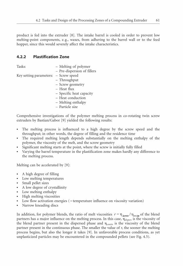
In addition, for polymer blends, the ratio of melt viscosities of the blendpartners has a major influence on the melting process. In this case, ndispers is the viscosity ofthe blend partner present in the dispersed phase and ncontin is the viscosity of the blendpartner present in the continuous phase. The smaller the value of r, the sooner the meltingprocess begins, but also the longer it takes [9]. In unfavorable process conditions, as yetunplasticized particles may be encountered in the compounded pellets (see Fig. 4.5).
4.2 Tasks and Design of the Processing Zones of a Compounding Extruder 61
0 5 0 1 0 0 1 5 0 2 0 0 2 5 0 3 0 0 3 5 0 4 0 0 4 5 0 5 0 0 5 5 0 6 0 0 [m m ]
1234
Materialaufgabe
FeststoffförderzoneKnetblockanordnung
Probe:
Feststoffanteil: 54%39%25%7%
0 5 0 1 0 0 1 5 0 2 0 0 2 5 0 3 0 0 3 5 0 4 0 0 4 5 0 5 0 0 5 5 0 6 0 0 [m m ]
1234
Material feeding
Solid conveying zoneKneading block assembly
Sample:
Solid content: 54%39%25%7%
The addition of low-viscosity additives can impede the formation of the melt film that isessential for melting. On the other hand, high-viscosity or solid additives can causeincreased energy dissipation due to internal and external friction, which accelerates theformation of the melt film but can also lead to overheating of the viscous phase.
Along with the actual melting, part of the key tasks of dispersion and homogenization alsotakes place in the plastification zone.
Figure 4.5: Unplasticized particles (so-called windows) within a single pellet
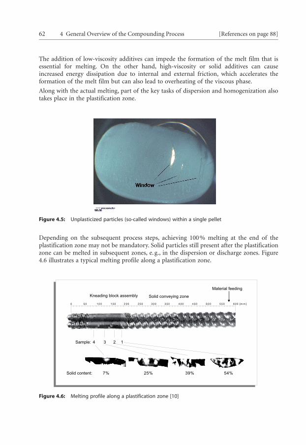
Depending on the subsequent process steps, achieving 100% melting at the end of theplastification zone may not be mandatory. Solid particles still present after the plastificationzone can be melted in subsequent zones, e.g., in the dispersion or discharge zones. Figure4.6 illustrates a typical melting profile along a plastification zone.
Figure 4.6: Melting profile along a plastification zone [10]
62 4 General Overview of the Compounding Process [References on page 88]
Smaller disc width
Enhanced mixing effect Reduced shear Increased product transport
Enhanced mixing effect Reduced product transport
Largerstaggering angle
The energy required to melt the polymer components is largely transmitted via the screwshafts; the heat flow through the barrel wall serves only to form a melt film on the wall [6].This melt film is important to create an adhesion of the polymer on the wall, thusgenerating a shear gradient [11]. To achieve this, the temperature of the barrel wall must behigher than the softening point of the polymer.
Up to 80% of the overall mechanical energy input in the twin screw extruder takes place inthe plastification zone. Unfortunately, currently only rudimentary modeling capacities forthe melting process are available.
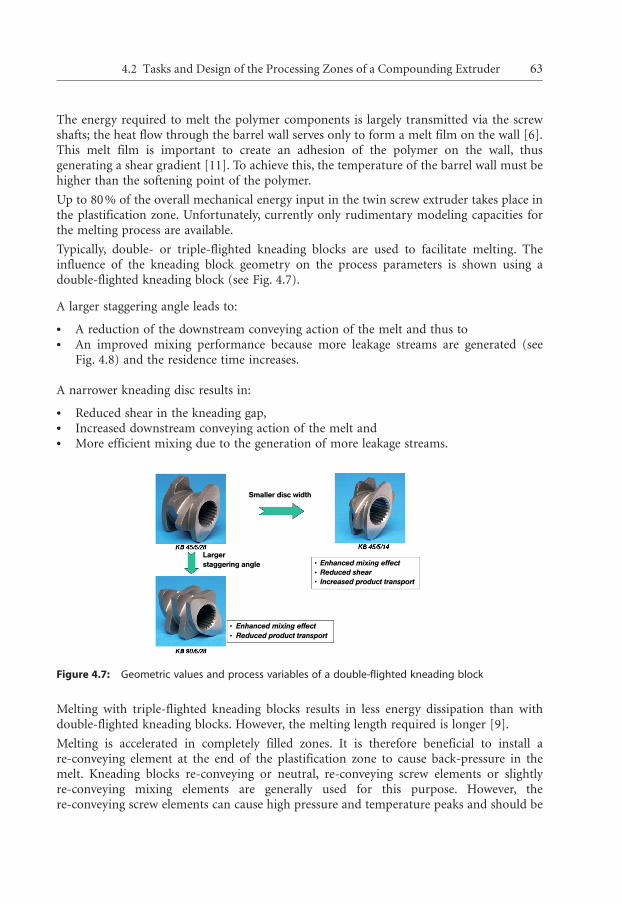
Typically, double- or triple-flighted kneading blocks are used to facilitate melting. Theinfluence of the kneading block geometry on the process parameters is shown using adouble-flighted kneading block (see Fig. 4.7).
A larger staggering angle leads to:
> A reduction of the downstream conveying action of the melt and thus to> An improved mixing performance because more leakage streams are generated (see
Fig. 4.8) and the residence time increases.
A narrower kneading disc results in:
> Reduced shear in the kneading gap,> Increased downstream conveying action of the melt and> More efficient mixing due to the generation of more leakage streams.
Figure 4.7: Geometric values and process variables of a double-flighted kneading block
Melting with triple-flighted kneading blocks results in less energy dissipation than withdouble-flighted kneading blocks. However, the melting length required is longer [9].
Melting is accelerated in completely filled zones. It is therefore beneficial to install are-conveying element at the end of the plastification zone to cause back-pressure in themelt. Kneading blocks re-conveying or neutral, re-conveying screw elements or slightlyre-conveying mixing elements are generally used for this purpose. However, there-conveying screw elements can cause high pressure and temperature peaks and should be
4.2 Tasks and Design of the Processing Zones of a Compounding Extruder 63
0.20
0.18
0.16
0.14
0.12
0.10
100 400 200 300 700 500 600
Specific
energ
y [
kW
h/k
g]
Throughput [kg/h]
KB configuration
MPE configuration 1
(3 mixing chambers)
MPE configuration 2
(2 mixing chambers)
Boundary conditions:
- ZE 40 A x 20 D UTX
- PA 6
- 0.5 kg`min/h
Figure 4.8: Melt streams in a kneading block zone – broad primary stream in the feed direction andnarrow leakage flow [12]
avoided as far as possible (see Chapter 8). For complex melting operations, e.g., with high/low-viscosity multicomponent mixtures, sieve discs can also be used to create back-pressure,provided that the higher energy input generated by these discs is admissible.
If the basic polymer is a fine powder, or if it is necessary to incorporate low bulk-densityfillers in large quantities, the plastification zone should be operated partially filled to preventfluidization in the intake zone. Partial filling can be achieved when the plastification zoneonly consists of forward pumping kneading blocks and there are no re-conveying elementsat the end of the plastification zone. In this case, however, the melting length must beconsiderably longer.
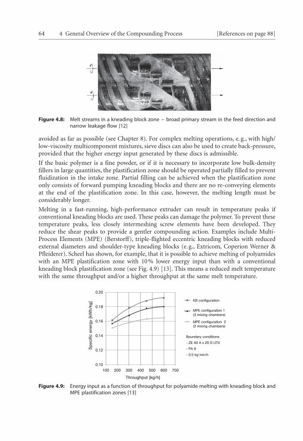
Melting in a fast-running, high-performance extruder can result in temperature peaks ifconventional kneading blocks are used. These peaks can damage the polymer. To prevent thesetemperature peaks, less closely intermeshing screw elements have been developed. Theyreduce the shear peaks to provide a gentler compounding action. Examples include Multi-Process Elements (MPE) (Berstorff), triple-flighted eccentric kneading blocks with reducedexternal diameters and shoulder-type kneading blocks (e.g., Extricom, Coperion Werner &Pfleiderer). Scheel has shown, for example, that it is possible to achieve melting of polyamideswith an MPE plastification zone with 10% lower energy input than with a conventionalkneading block plastification zone (see Fig. 4.9) [13]. This means a reduced melt temperaturewith the same throughput and/or a higher throughput at the same melt temperature.
Figure 4.9: Energy input as a function of throughput for polyamide melting with kneading block andMPE plastification zones [13]
64 4 General Overview of the Compounding Process [References on page 88]