Computer Aided Design - Hochschule Ravensburg …nosper/public/Download/Kapitel 2.5...
12
Mechatronische Systemtechnik im KFZ Kapitel 2: Simulation Prof. Dr.-Ing. Tim J. Nosper Bild 2.5_1 Computer Aided Design - Computer Aided Software Engineering Quelle: Autom.Eng.Partners Mechatronische Systemtechnik im KFZ Kapitel 2: Simulation Prof. Dr.-Ing. Tim J. Nosper Bild 2.5_2 Mehrkörpersystem
Transcript of Computer Aided Design - Hochschule Ravensburg …nosper/public/Download/Kapitel 2.5...
Mechatronische Systemtechnik im KFZ Kapitel 2: Simulation Prof. Dr.-Ing. Tim J. Nosper
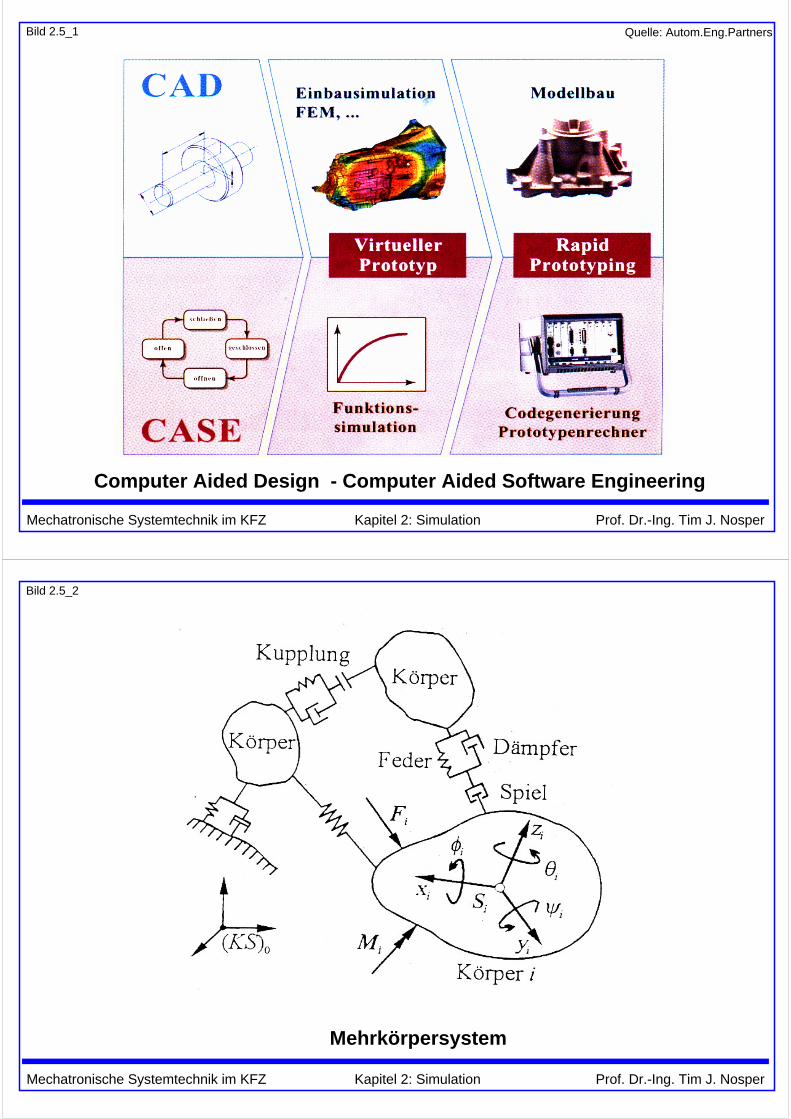
Bild 2.5_1
Computer Aided Design - Computer Aided Software Engineering
Quelle: Autom.Eng.Partners
Mechatronische Systemtechnik im KFZ Kapitel 2: Simulation Prof. Dr.-Ing. Tim J. Nosper
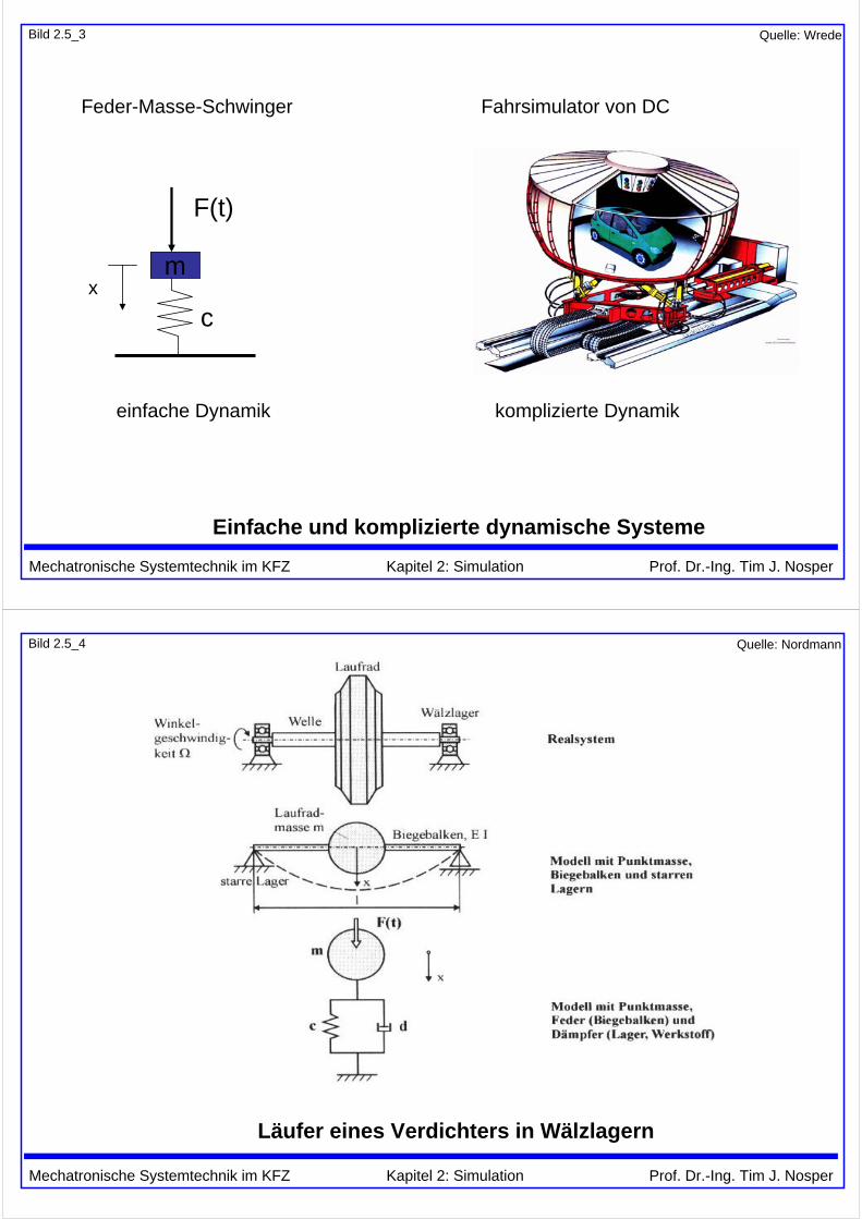
Bild 2.5_2
Mehrkörpersystem
Mechatronische Systemtechnik im KFZ Kapitel 2: Simulation Prof. Dr.-Ing. Tim J. Nosper
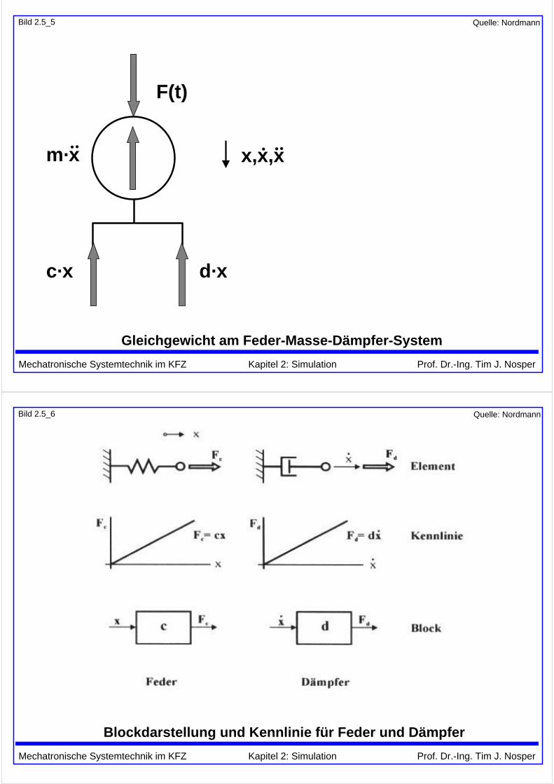
Bild 2.5_3
Einfache und komplizierte dynamische Systeme
Feder-Masse-Schwinger Fahrsimulator von DC
einfache Dynamik komplizierte Dynamik
m
c
F(t)
x
Quelle: Wrede
Mechatronische Systemtechnik im KFZ Kapitel 2: Simulation Prof. Dr.-Ing. Tim J. Nosper
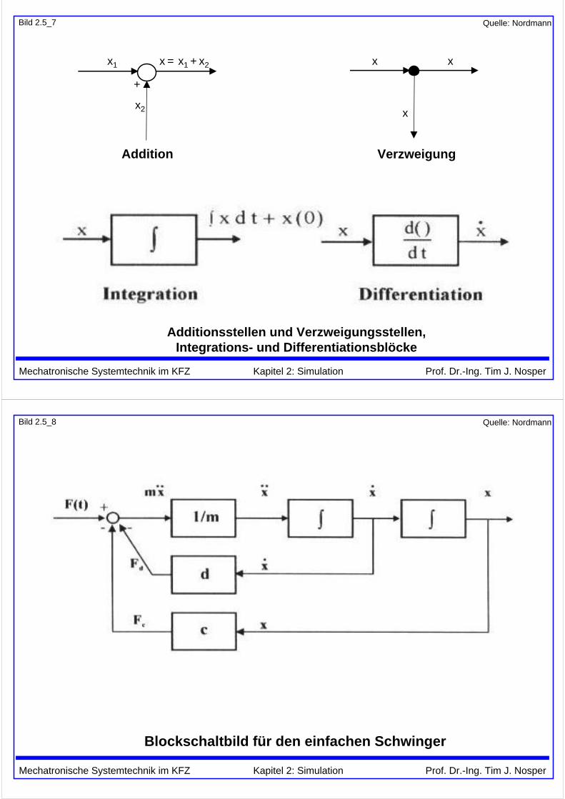
Bild 2.5_4
Läufer eines Verdichters in Wälzlagern
Quelle: Nordmann
Mechatronische Systemtechnik im KFZ Kapitel 2: Simulation Prof. Dr.-Ing. Tim J. Nosper
Bild 2.5_5
Gleichgewicht am Feder-Masse-Dämpfer-System
Quelle: Nordmann
F(t)
m·x x,x,x
c·x d·x
Mechatronische Systemtechnik im KFZ Kapitel 2: Simulation Prof. Dr.-Ing. Tim J. Nosper
Bild 2.5_6
Blockdarstellung und Kennlinie für Feder und Dämpfer
Quelle: Nordmann
Mechatronische Systemtechnik im KFZ Kapitel 2: Simulation Prof. Dr.-Ing. Tim J. Nosper
Bild 2.5_7
x1
x2
x = x1 + x2
+
x
x
x
Additionsstellen und Verzweigungsstellen,Integrations- und Differentiationsblöcke
Quelle: Nordmann
Addition Verzweigung
Mechatronische Systemtechnik im KFZ Kapitel 2: Simulation Prof. Dr.-Ing. Tim J. Nosper
Bild 2.5_8
Blockschaltbild für den einfachen Schwinger
Quelle: Nordmann
Mechatronische Systemtechnik im KFZ Kapitel 2: Simulation Prof. Dr.-Ing. Tim J. Nosper
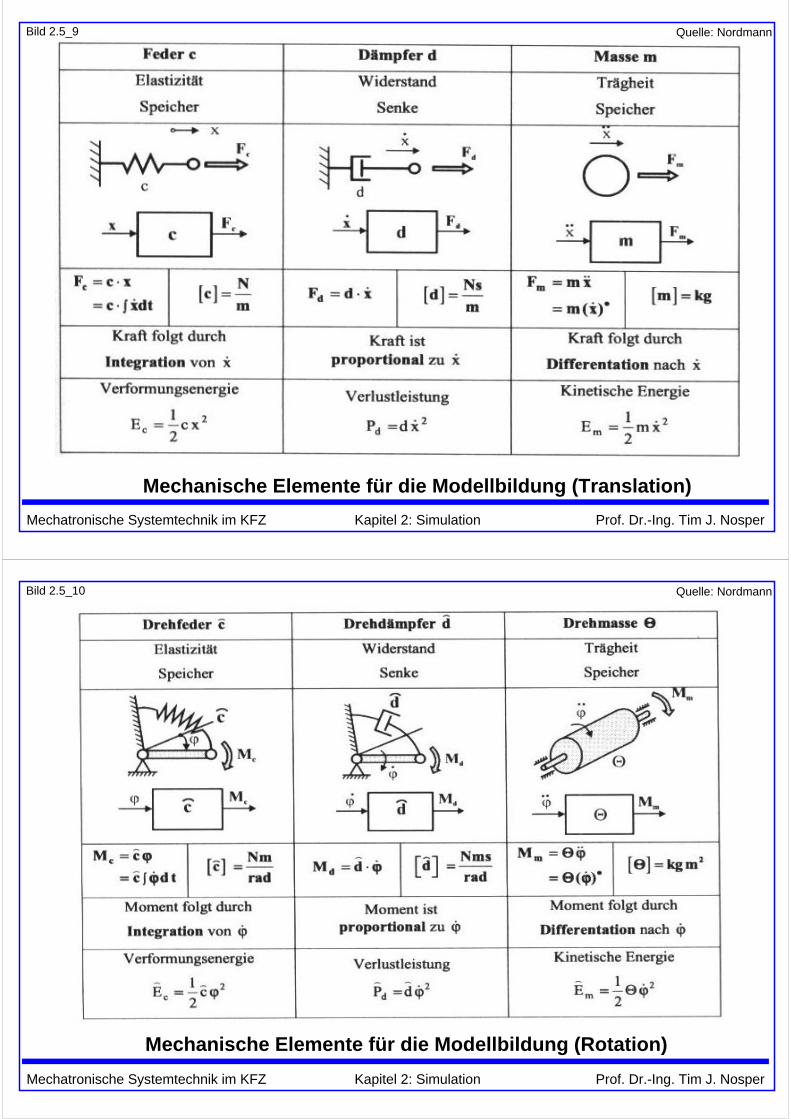
Bild 2.5_9
Mechanische Elemente für die Modellbildung (Translation)
Quelle: Nordmann
Mechatronische Systemtechnik im KFZ Kapitel 2: Simulation Prof. Dr.-Ing. Tim J. Nosper
Bild 2.5_10
Mechanische Elemente für die Modellbildung (Rotation)
Quelle: Nordmann
Mechatronische Systemtechnik im KFZ Kapitel 2: Simulation Prof. Dr.-Ing. Tim J. Nosper
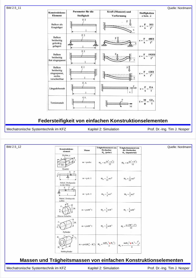
Bild 2.5_11
Federsteifigkeit von einfachen Konstruktionselementen
Quelle: Nordmann
Mechatronische Systemtechnik im KFZ Kapitel 2: Simulation Prof. Dr.-Ing. Tim J. Nosper
Bild 2.5_12
Massen und Trägheitsmassen von einfachen Konstruktionselementen
Quelle: Nordmann
+ +
Mechatronische Systemtechnik im KFZ Kapitel 2: Simulation Prof. Dr.-Ing. Tim J. Nosper
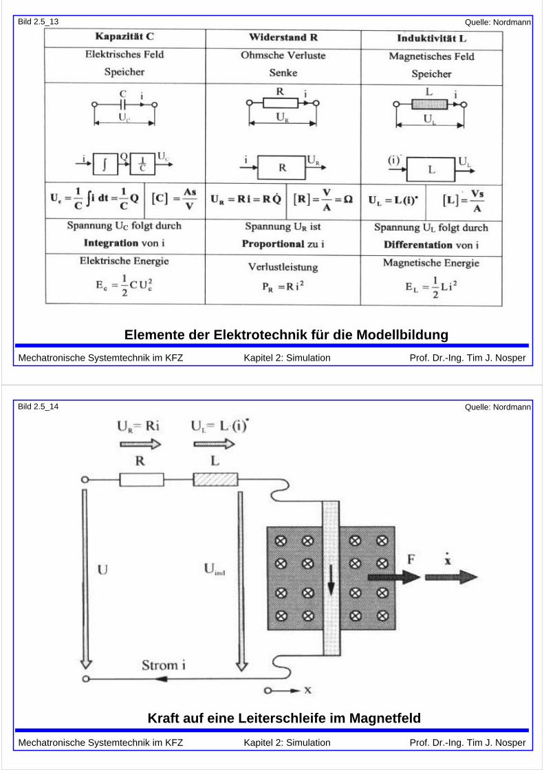
Bild 2.5_13
Elemente der Elektrotechnik für die Modellbildung
Quelle: Nordmann
Mechatronische Systemtechnik im KFZ Kapitel 2: Simulation Prof. Dr.-Ing. Tim J. Nosper
Bild 2.5_14
Kraft auf eine Leiterschleife im Magnetfeld
Quelle: Nordmann
Mechatronische Systemtechnik im KFZ Kapitel 2: Simulation Prof. Dr.-Ing. Tim J. Nosper
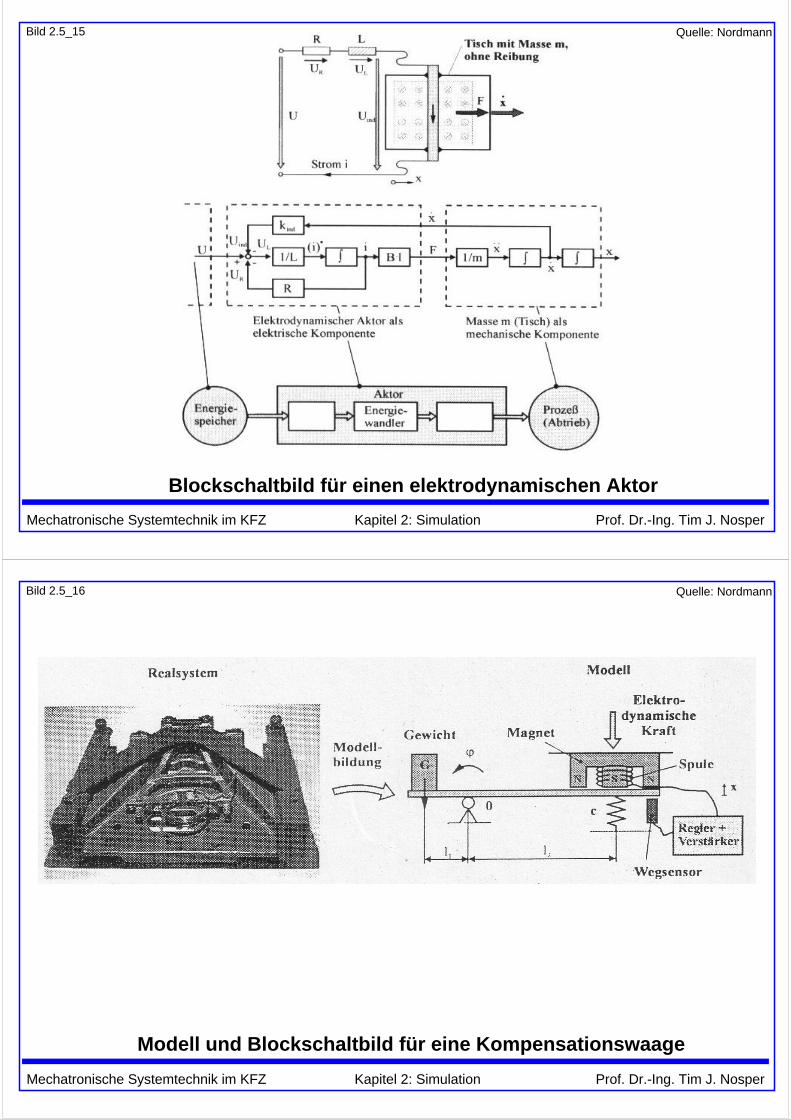
Bild 2.5_15
Blockschaltbild für einen elektrodynamischen Aktor
Quelle: Nordmann
Mechatronische Systemtechnik im KFZ Kapitel 2: Simulation Prof. Dr.-Ing. Tim J. Nosper
Bild 2.5_16
Modell und Blockschaltbild für eine Kompensationswaage
Quelle: Nordmann
Mechatronische Systemtechnik im KFZ Kapitel 2: Simulation Prof. Dr.-Ing. Tim J. Nosper
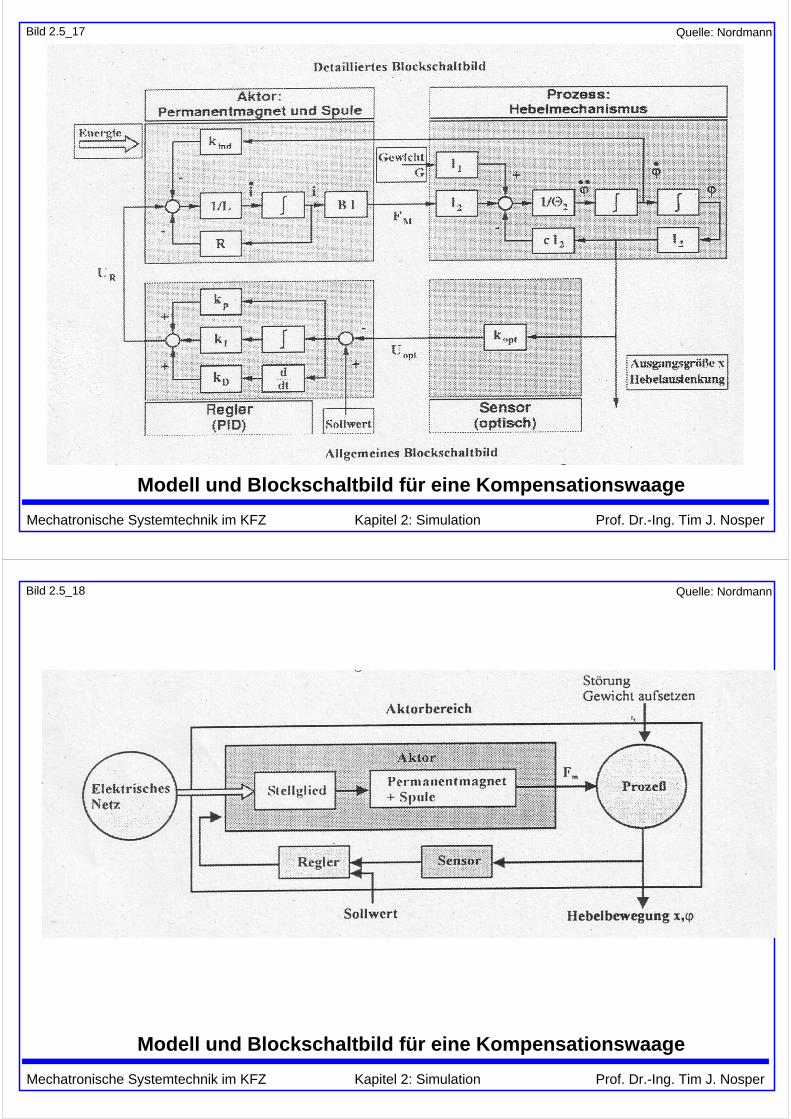
Bild 2.5_17
Modell und Blockschaltbild für eine Kompensationswaage
Quelle: Nordmann
Mechatronische Systemtechnik im KFZ Kapitel 2: Simulation Prof. Dr.-Ing. Tim J. Nosper
Bild 2.5_18
Modell und Blockschaltbild für eine Kompensationswaage
Quelle: Nordmann
Mechatronische Systemtechnik im KFZ Kapitel 2: Simulation Prof. Dr.-Ing. Tim J. Nosper
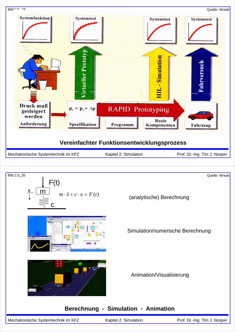
Bild 2.5_19
Vereinfachter Funktionsentwicklungsprozess
Quelle: Wrede
Mechatronische Systemtechnik im KFZ Kapitel 2: Simulation Prof. Dr.-Ing. Tim J. Nosper
Bild 2.5_20
Berechnung - Simulation - Animation
(analytische) Berechnung
Simulation/numerische Berechnung
Animation/Visualisierung
m
c
F(t)
)(tFxcxm =⋅+⋅ &&x
Quelle: Wrede

Mechatronische Systemtechnik im KFZ Kapitel 2: Simulation Prof. Dr.-Ing. Tim J. Nosper
Bild 2.5_21
Simulation: Mikrocontroller-Software und physikalische Systeme
Störgrößen (Bremse, Wind,..)v_set
+-
v_ist
v_soll
Regler
DAC
Sollwert-geber
Fahrervorgabe
PIMotor-momentAD
D A
ADC
AD
ADCTempomat-Software
Mikrocontroller-SW:
real: zeitdiskret z.B. T = 10 ms simuliert: zeitdiskret z.B. T = 10 ms
real: wertediskret z.B. v als 16-bit-Int. simuliert: wertediskret z.B. v als 16-bit-Int.
Physikalische Systeme:
real: zeitkontinuierlich simuliert: zeitdiskret, z.B. T = 1 ms
real: wertekontinuierlich simuliert: wertediskret, z.B. v als double (64 bit), quasi-kont.
Geschwindigkeit v
Quelle: Wrede
Mechatronische Systemtechnik im KFZ Kapitel 2: Simulation Prof. Dr.-Ing. Tim J. Nosper
Bild 2.5_22
Arbeitsschritte der Simulation (z.B. Matlab/Simulink)
1) Modellbildung durchführenAbstraktion und Ableitung des physikalischen Modells vom realen Gerät
2) Mathematische Modellbeschreibung erstellenBeschreibung des Modells durch algebraische und Differentialgleichungen
3) Umformen in lösungsorientierte DarstellungMathematische Transformation/Umrechnung in für Programmierunggeeignete Form, z.B. Integralgleichungen, Strukturbild, etc.
4) Eingabe der Struktur/Parameter in SimulationsprogrammDateneingabe z.B. in MATLAB/Simulink
5) Auswahl eines geeigneten IntegrationsverfahrensDas Simulationsprogramm bietet meist mehrere Möglichkeiten.
6) Abarbeitung des SimulationszyklusAnfangsbedingungen, Schleife über mehrere Zeitschritte, Ergebnisdarstellung
Quelle: Wrede
Mechatronische Systemtechnik im KFZ Kapitel 2: Simulation Prof. Dr.-Ing. Tim J. Nosper
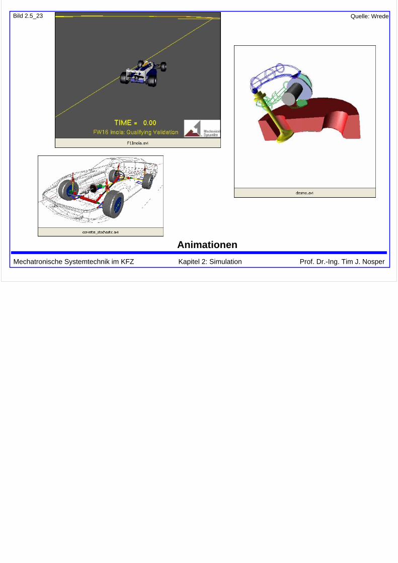
Bild 2.5_23
Animationen
Quelle: Wrede