CONTACTORS & THERMAL OVERLOAD RELAYS · 4 Magnetic contactors Thermal overload relays Easy to use...
72
CONTACTORS & THERMAL OVERLOAD RELAYS CONTACTORS & THERMAL OVERLOAD RELAYS Meta - MEC Series
Transcript of CONTACTORS & THERMAL OVERLOAD RELAYS · 4 Magnetic contactors Thermal overload relays Easy to use...
CONT
ACTO
RS &
THER
MAL O
VERL
OAD R
ELAY
S
CONTACTORS & THERMAL OVERLOAD RELAYS
Met
a-
ME
C S
erie
s

2
customer satisfaction
Think&
FFuullll--sseerriieess ffrroomm 99~~~880000AAFF
TThhee lloonngg lliiffee
CCeerrttiiffiiccaattiioonn aanndd AApppprroovvaall ffrroomm
aauutthhoorriizzeedd tteesstt llaabb
The long Life Meta-MEC
Certification & Approval : CE, UL / CSA, Lloyd Register, Korea Register, KS, ISO 14001, ISO 9001(Including proceedings), TSE, PSE
Standard : IEC 60947, UL 508, VDE 0660, EN 60947, BS 5424, KS C 4504
3
Research
GMC Type
1. Selection guide Technical information3-pole Contactors description 4~53-pole Contactors and Thermal overload relays 6~74-pole Contactors 8Type designation 93 & 4-pole Contactors technical information 10Contactor relays 22~23Accessories 24~26Reversing contactors 27~28Latching contactors 292-pole AC magnetic contactor 30~31Contactors with delay open device 32Thermal overload relays 33~37Thermal overload relays (class20) 38~39Enclosures for direct starters 40~43
2. Dimensions and wiring diagrams3-pole Contactors 44~47Direct starters 48~494-pole contactors 50~52Contactor relays 53~54Auxiliary contact blocks 55Reversing contactors 56~61Reversing contactors with TOR 62~64Latching contactors 65~66Contactors with delayed open device 67Thermal overload relays 68~69Thermal overload relays (class20) 70~71
CC OO NN TT EE NN TT SS
M E T A - M E C S E R I E S
4
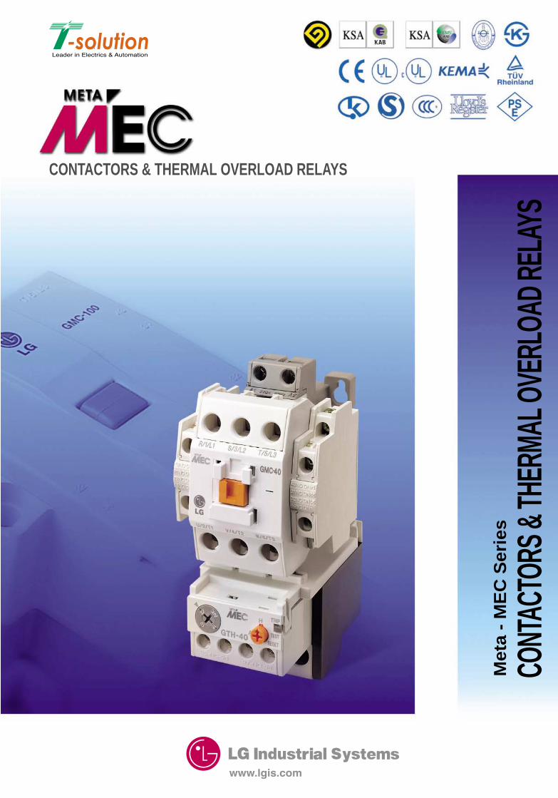
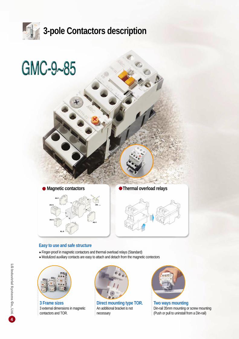
Magnetic contactors Thermal overload relays
Easy to use and safe structure●Finger-proof in magnetic contactors and thermal overload relays (Standard)●Modulized auxiliary contacts are easy to attach and detach from the magnetic contectors
3 Frame sizes3 external dimensions in magneticcontactors and TOR.
Direct mounting type TOR.An additional bracket is notnecessary
Two ways mountingDin-rail 35mm mounting or screw mounting(Push or pull to uninstall from a Din-rail)
3-pole Contactors description
5
M E T A - M E C S E R I E S
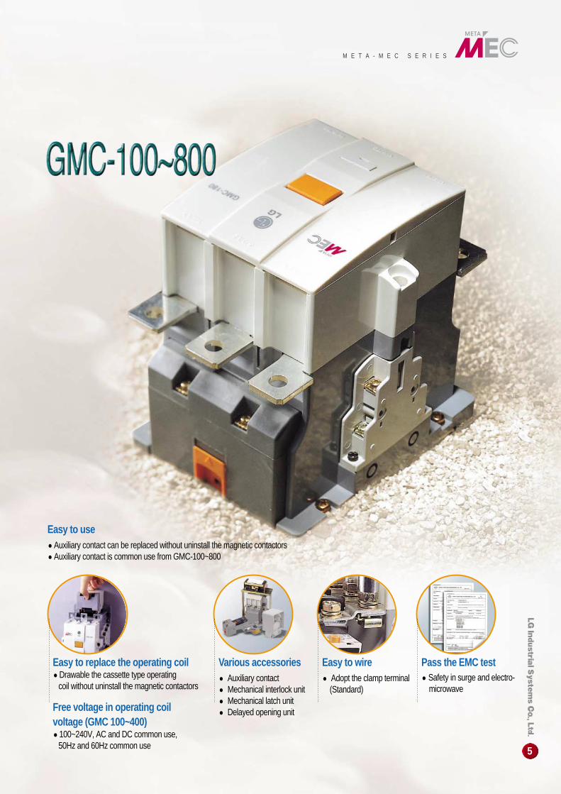
Easy to use●Auxiliary contact can be replaced without uninstall the magnetic contactors ●Auxiliary contact is common use from GMC-100~800
Easy to replace the operating coil●Drawable the cassette type operating
coil without uninstall the magnetic contactors
Free voltage in operating coil voltage (GMC 100~400)●100~240V, AC and DC common use,
50Hz and 60Hz common use
Various accessories● Auxiliary contact● Mechanical interlock unit● Mechanical latch unit● Delayed opening unit
Easy to wire● Adopt the clamp terminal
(Standard)
Pass the EMC test● Safety in surge and electro-
microwave
6
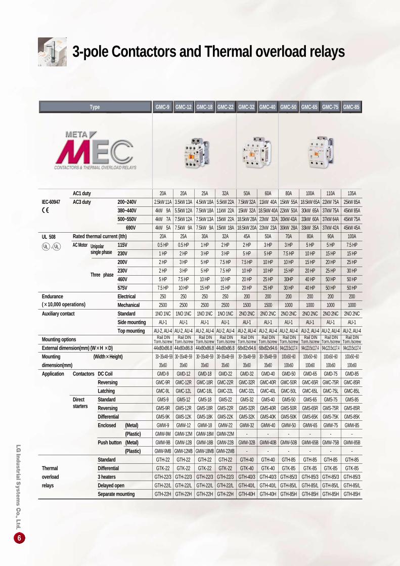
AC1 duty 20A 20A 25A 32A 50A 60A 80A 100A 110A 135A
IEC-60947 AC3 duty 200~240V 2.5kW 11A 3.5kW 13A 4.5kW 18A 5.5kW 22A 7.5kW 32A 11kW 40A 15kW 55A 18.5kW 65A 22kW 75A 25kW 85A
380~440V 4kW 9A 5.5kW 12A 7.5kW 18A 11kW 22A 15kW 32A 18.5kW 40A 22kW 50A 30kW 65A 37kW 75A 45kW 85A
500~550V 4kW 7A 7.5kW 12A 7.5kW 13A 15kW 22A 18.5kW 28A 22kW 32A 30kW 43A 33kW 60A 37kW 64A 45kW 75A
690V 4kW 5A 7.5kW 9A 7.5kW 9A 15kW 18A 18.5kW 20A 22kW 23A 30kW 28A 33kW 35A 37kW 42A 45kW 45A
Rated thermal current (Ith) 20A 25A 30A 32A 45A 50A 70A 80A 90A 100AUL 508 AC Motor Unipolar 115V 0.5 HP 0.5 HP 1 HP 2 HP 2 HP 3 HP 3 HP 5 HP 5 HP 7.5 HP
single phase 230V 1 HP 2 HP 3 HP 3 HP 5 HP 5 HP 7.5 HP 10 HP 15 HP 15 HP
200V 2 HP 3 HP 5 HP 7.5 HP 7.5 HP 10 HP 10 HP 15 HP 20 HP 25 HP
Three phase230V 2 HP 3 HP 5 HP 7.5 HP 10 HP 10 HP 15 HP 20 HP 25 HP 30 HP
460V 5 HP 7.5 HP 10 HP 10 HP 20 HP 25 HP 30HP 40 HP 50 HP 50 HP
575V 7.5 HP 10 HP 15 HP 15 HP 20 HP 25 HP 30 HP 40 HP 50 HP 50 HP
Endurance Electrical 250 250 250 250 200 200 200 200 200 200 (××10,000 operations) Mechanical 2500 2500 2500 2500 1500 1500 1000 1000 1000 1000
Auxiliary contact Standard 1NO 1NC 1NO 1NC 1NO 1NC 1NO 1NC 2NO 2NC 2NO 2NC 2NO 2NC 2NO 2NC 2NO 2NC 2NO 2NC
Side mounting AU-1 AU-1 AU-1 AU-1 AU-1 AU-1 AU-1 AU-1 AU-1 AU-1
Top mounting AU-2, AU-4 AU-2, AU-4 AU-2, AU-4 AU-2, AU-4 AU-2, AU-4 AU-2, AU-4 AU-2, AU-4 AU-2, AU-4 AU-2, AU-4 AU-2, AU-4
Mounting options
External dimension(mm) (W ××H ××D) 44x80x86.8 44x80x86.8 44x80x86.8 44x80x86.8 68x82x94.6 68x82x94.6 94x123.5x117.4 94x123.5x117.4 94x123.5x117.4 94x123.5x117.4
Mounting (Width××Height) 30~35x48~59 30~35x48~59 30~35x48~59 30~35x48~59 30~35x48~59 30~35x48~59 100x50~60 100x50~60 100x50~60 100x50~60
dimension(mm) 35x60 35x60 35x60 35x60 35x60 35x60 100x60 100x60 100x60 100x60
Application Contactors DC Coil GMD-9 GMD-12 GMD-18 GMD-22 GMD-32 GMD-40 GMD-50 GMD-65 GMD-75 GMD-85
Reversing GMC-9R GMC-12R GMC-18R GMC-22R GMC-32R GMC-40R GMC-50R GMC-65R GMC-75R GMC-85R
Latching GMC-9L GMC-12L GMC-18L GMC-22L GMC-32L GMC-40L GMC-50L GMC-65L GMC-75L GMC-85L
Direct Standard GMS-9 GMS-12 GMS-18 GMS-22 GMS-32 GMS-40 GMS-50 GMS-65 GMS-75 GMS-85 starters Reversing GMS-9R GMS-12R GMS-18R GMS-22R GMS-32R GMS-40R GMS-50R GMS-65R GMS-75R GMS-85R
Differential GMS-9K GMS-12K GMS-18K GMS-22K GMS-32K GMS-40K GMS-50K GMS-65K GMS-75K GMS-85K
Enclosed (Metal) GMW-9 GMW-12 GMW-18 GMW-22 GMW-32 GMW-40 GMW-50 GMW-65 GMW-75 GMW-85
(Plastic) GMW-9M GMW-12M GMW-18M GMW-22M - - - - - -
Push button (Metal) GMW-9B GMW-12B GMW-18B GMW-22B GMW-32B GMW-40B GMW-50B GMW-65B GMW-75B GMW-85B
(Plastic) GMW-9MB GMW-12MB GMW-18MB GMW-22MB - - - - - -
Standard GTH-22 GTH-22 GTH-22 GTH-22 GTH-40 GTH-40 GTH-85 GTH-85 GTH-85 GTH-85
Thermal Differential GTK-22 GTK-22 GTK-22 GTK-22 GTK-40 GTK-40 GTK-85 GTK-85 GTK-85 GTK-85
overload 3 heaters GTH-22/3 GTH-22/3 GTH-22/3 GTH-22/3 GTH-40/3 GTH-40/3 GTH-85/3 GTH-85/3 GTH-85/3 GTH-85/3
relays Delayed open GTH-22/L GTH-22/L GTH-22/L GTH-22/L GTH-40/L GTH-40/L GTH-85/L GTH-85/L GTH-85/L GTH-85/L
Separate mounting GTH-22H GTH-22H GTH-22H GTH-22H GTH-40H GTH-40H GTH-85H GTH-85H GTH-85H GTH-85H
Rail DINTorn./screw
Rail DINTorn./screw
Rail DINTorn./screw
Rail DINTorn./screw
Rail DINTorn./screw
Rail DINTorn./screw
Rail DINTorn./screw
Rail DINTorn./screw
Rail DINTorn./screw
Rail DINTorn./screw
GMC-9Type GMC-12 GMC-18 GMC-22 GMC-32 GMC-40 GMC-50 GMC-65 GMC-75 GMC-85
3-pole Contactors and Thermal overload relays
7
M E T A - M E C S E R I E S
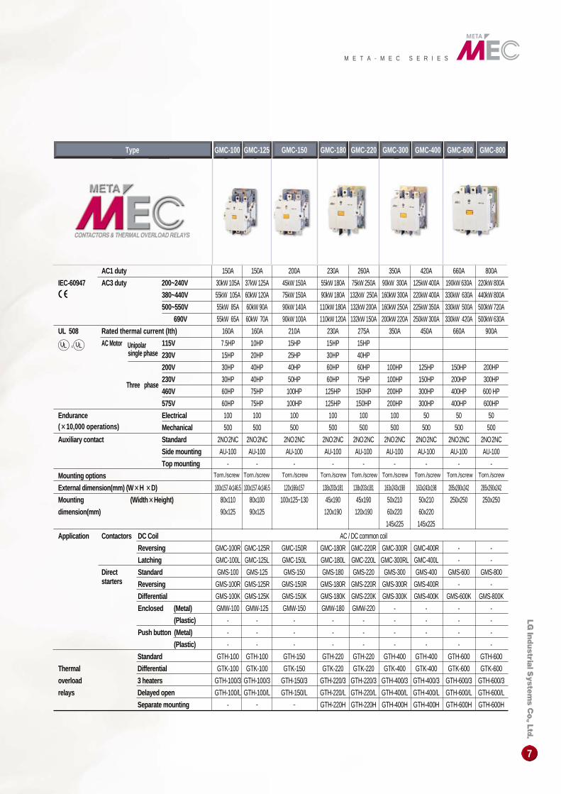
GMC-100Type GMC-125 GMC-150 GMC-600 GMC-800GMC-300GMC-180 GMC-220 GMC-400
AC1 duty 150A 150A 200A 230A 260A 350A 420A 660A 800A
IEC-60947 AC3 duty 200~240V 30kW 105A 37kW 125A 45kW 150A 55kW 180A 75kW 250A 90kW 300A 125kW 400A 190kW 630A 220kW 800A
380~440V 55kW 105A 60kW 120A 75kW 150A 90kW 180A 132kW 250A 160kW 300A 220kW 400A 330kW 630A 440kW 800A
500~550V 55kW 85A 60kW 90A 90kW 140A 110kW 180A 132kW 200A 160kW 250A 225kW 350A 330kW 500A 500kW 720A
690V 55kW 65A 60kW 70A 90kW 100A 110kW 120A 132kW 150A 200kW 220A 250kW 300A 330kW 420A 500kW 630A
UL 508 Rated thermal current (Ith) 160A 160A 210A 230A 275A 350A 450A 660A 900A
AC Motor Unipolar 115V 7.5HP 10HP 15HP 15HP 15HPsingle phase 230V 15HP 20HP 25HP 30HP 40HP
200V 30HP 40HP 40HP 60HP 60HP 100HP 125HP 150HP 200HP
Three phase230V 30HP 40HP 50HP 60HP 75HP 100HP 150HP 200HP 300HP
460V 60HP 75HP 100HP 125HP 150HP 200HP 300HP 400HP 600 HP
575V 60HP 75HP 100HP 125HP 150HP 200HP 300HP 400HP 600HP
Endurance Electrical 100 100 100 100 100 100 50 50 50(××10,000 operations) Mechanical 500 500 500 500 500 500 500 500 500
Auxiliary contact Standard 2NO2NC 2NO2NC 2NO2NC 2NO2NC 2NO2NC 2NO2NC 2NO2NC 2NO2NC 2NO2NC
Side mounting AU-100 AU-100 AU-100 AU-100 AU-100 AU-100 AU-100 AU-100 AU-100
Top mounting - - - - - - - - -
Mounting options
External dimension(mm) (W ××H ××D) 100x157.4x146.5 100x157.4x146.5 120x166x157 138x203x181 138x203x181 163x243x198 163x243x198 285x290x242 285x290x242
Mounting (Width ××Height) 80x110 80x100 100x125~130 45x190 45x190 50x210 50x210 250x250 250x250
dimension(mm) 90x125 90x125 120x190 120x190 60x220 60x220
145x225 145x225
Application Contactors DC Coil AC / DC common coil
Reversing GMC-100R GMC-125R GMC-150R GMC-180R GMC-220R GMC-300R GMC-400R - -
Latching GMC-100L GMC-125L GMC-150L GMC-180L GMC-220L GMC-300RL GMC-400L - -
Direct Standard GMS-100 GMS-125 GMS-150 GMS-180 GMS-220 GMS-300 GMS-400 GMS-600 GMS-800 starters Reversing GMS-100R GMS-125R GMS-150R GMS-180R GMS-220R GMS-300R GMS-400R - -
Differential GMS-100K GMS-125K GMS-150K GMS-180K GMS-220K GMS-300K GMS-400K GMS-600K GMS-800K
Enclosed (Metal) GMW-100 GMW-125 GMW-150 GMW-180 GMW-220 - - - -
(Plastic) - - - - - - - - -
Push button (Metal) - - - - - - - - -
(Plastic) - - - - - - - - -
Standard GTH-100 GTH-100 GTH-150 GTH-220 GTH-220 GTH-400 GTH-400 GTH-600 GTH-600
Thermal Differential GTK-100 GTK-100 GTK-150 GTK-220 GTK-220 GTK-400 GTK-400 GTK-600 GTK-600
overload 3 heaters GTH-100/3 GTH-100/3 GTH-150/3 GTH-220/3 GTH-220/3 GTH-400/3 GTH-400/3 GTH-600/3 GTH-600/3
relays Delayed open GTH-100/L GTH-100/L GTH-150/L GTH-220/L GTH-220/L GTH-400/L GTH-400/L GTH-600/L GTH-600/L
Separate mounting - - - GTH-220H GTH-220H GTH-400H GTH-400H GTH-600H GTH-600H
Torn./screw Torn./screw Torn./screw Torn./screw Torn./screw Torn./screw Torn./screw Torn./screw Torn./screw
8
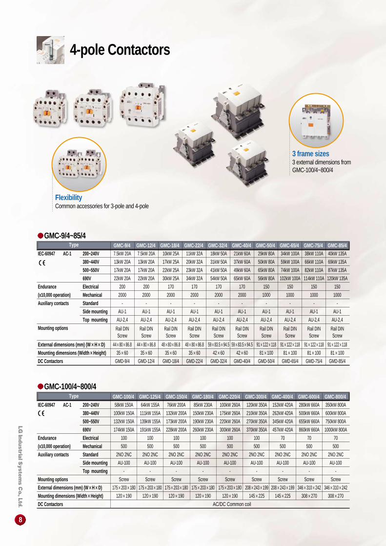
3 frame sizes3 external dimensions fromGMC-100/4~800/4
FlexibilityCommon accessories for 3-pole and 4-pole
IEC-60947 AC-1 200~240V
380~440V
500~550V
690V
Endurance Electrical
(x10,000 operation) Mechanical
Auxiliary contacts Standard
Side mounting
Top mounting
Mounting options
External dimensions (mm) (W ××H××D)
Mounting dimensions (Width ××Height)
DC Contactors
Type GMC-100/4 GMC-125/4 GMC-150/4 GMC-180/4 GMC-220/4 GMC-300/4 GMC-400/4 GMC-600/4 GMC-800/458kW 150A 64kW 155A 76kW 200A 85kW 230A 100kW 260A 120kW 350A 152kW 420A 280kW 660A 350kW 800A
100kW 150A 111kW 155A 132kW 200A 150kW 230A 175kW 260A 210kW 350A 262kW 420A 500kW 660A 600kW 800A
132kW 150A 139kW 155A 173kW 200A 190kW 230A 220kW 260A 270kW 350A 345kW 420A 655kW 660A 750kW 800A
174kW 150A 191kW 155A 228kW 200A 260kW 230A 300kW 260A 370kW 350A 457kW 420A 860kW 660A 1000kW 800A
100 100 100 100 100 100 70 70 70
500 500 500 500 500 500 500 500 500
2NO 2NC 2NO 2NC 2NO 2NC 2NO 2NC 2NO 2NC 2NO 2NC 2NO 2NC 2NO 2NC 2NO 2NC
AU-100 AU-100 AU-100 AU-100 AU-100 AU-100 AU-100 AU-100 AU-100
- - - - - - - - -
Screw Screw Screw Screw Screw Screw Screw Screw Screw
175×203×180 175×203×180 175×203×180 175×203×180 175×203×180 208×243×199 208×243×199 346×310×242 346×310×242
120×190 120×190 120×190 120×190 120×190 145×225 145×225 308×270 308×270
AC/DC Common coil
IEC-60947 AC-1 200~240V
380~440V
500~550V
690V
Endurance Electrical
(x10,000 operation) Mechanical
Auxiliary contacts Standard
Side mounting
Top mounting
Mounting options
External dimensions (mm) (W ××H××D)
Mounting dimensions (Width ××Height)
DC Contactors
GMC-9/4 GMC-12/4 GMC-18/4 GMC-22/4 GMC-32/4 GMC-40/4 GMC-50/4 GMC-65/4 GMC-75/4 GMC-85/47.5kW 20A 7.5kW 20A 10kW 25A 11kW 32A 18kW 50A 21kW 60A 29kW 80A 34kW 100A 38kW 110A 40kW 135A
13kW 20A 13kW 20A 17kW 25A 20kW 32A 31kW 50A 37kW 60A 50kW 80A 59kW 100A 66kW 110A 69kW 135A
17kW 20A 17kW 20A 22kW 25A 23kW 32A 41kW 50A 49kW 60A 65kW 80A 74kW 100A 82kW 110A 87kW 135A
22kW 20A 22kW 20A 30kW 25A 34kW 32A 54kW 50A 65kW 60A 56kW 80A 102kW 100A 114kW 110A 120kW 135A
200 200 170 170 170 170 150 150 150 150
2000 2000 2000 2000 2000 2000 1000 1000 1000 1000
- - - - - - - - - -
AU-1 AU-1 AU-1 AU-1 AU-1 AU-1 AU-1 AU-1 AU-1 AU-1
AU-2,4 AU-2,4 AU-2,4 AU-2,4 AU-2,4 AU-2,4 AU-2,4 AU-2,4 AU-2,4 AU-2,4
Rail DIN Rail DIN Rail DIN Rail DIN Rail DIN Rail DIN Rail DIN Rail DIN Rail DIN Rail DINScrew Screw Screw Screw Screw Screw Screw Screw Screw Screw
44×80×86.8 44×80×86.8 48×80×86.8 48×80×86.8 59×83.5×94.5 59×83.5×94.5 91×122×118 91×122×118 91×122×118 91×122×118
35×60 35×60 35×60 35×60 42×60 42×60 81×100 81×100 81×100 81×100
GMD-9/4 GMD-12/4 GMD-18/4 GMD-22/4 GMD-32/4 GMD-40/4 GMD-50/4 GMD-65/4 GMD-75/4 GMD-85/4
Type
GMC-9/4~85/4
GMC-100/4~800/4
4-pole Contactors
9
/
/
M E T A - M E C S E R I E S
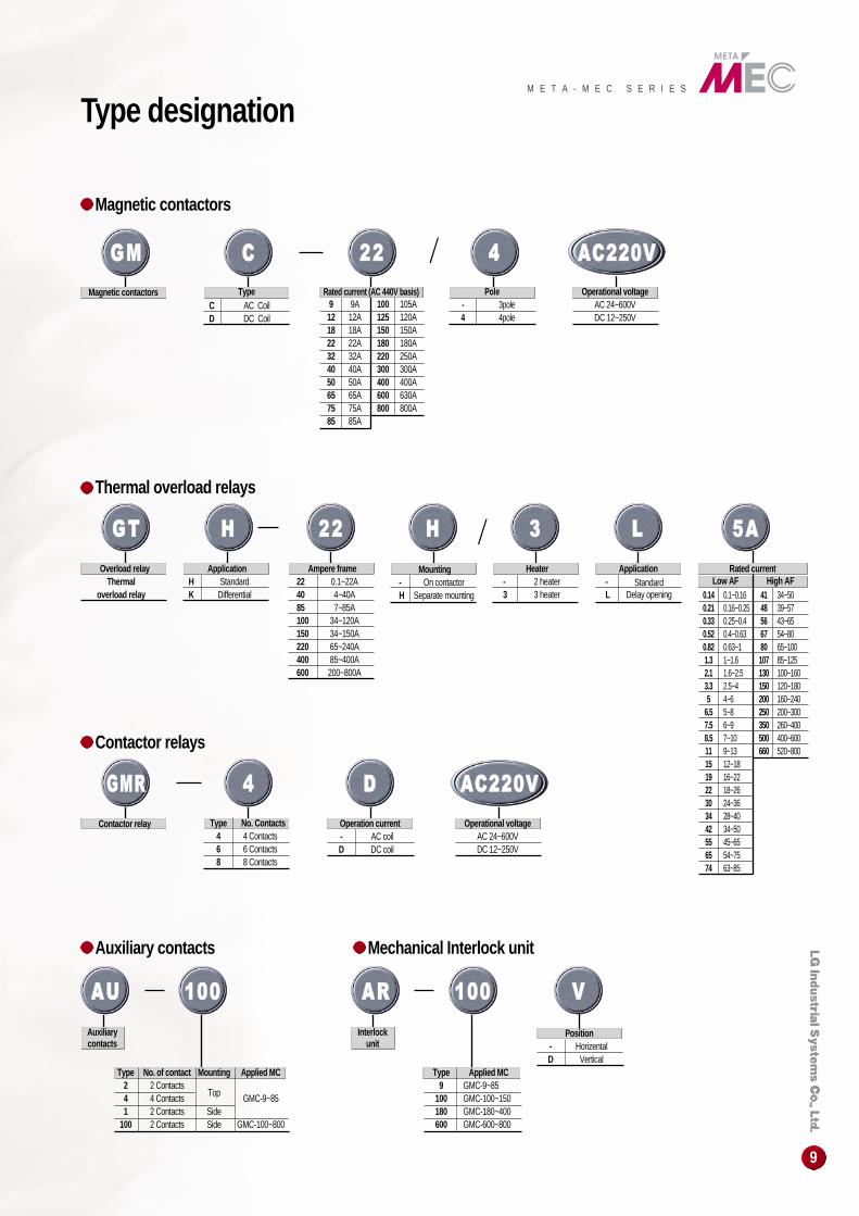
Rated current (AC 440V basis)9 9A12 12A18 18A22 22A32 32A40 40A50 50A65 65A75 75A85 85A
100 105A125 120A150 150A180 180A220 250A300 300A400 400A600 630A800 800A
GGMM
Magnetic contactors
CC
TypeC AC CoilD DC Coil
2222 44
Pole- 3pole4 4pole
AACC222200VV
Operational voltageAC 24~600VDC 12~250V
GGMMRR
Contactor relay
44
Type No. Contacts4 4 Contacts6 6 Contacts8 8 Contacts
DD
Operation current- AC coilD DC coil
AACC222200VV
Operational voltageAC 24~600VDC 12~250V
Position- HorizentalD Vertical
GGTT
Overload relayThermal
overload relay
HH
ApplicationH StandardK Differential
2222
Ampere frame22 0.1~22A40 4~40A85 7~85A100 34~120A150 34~150A220 65~240A400 85~400A600 200~800A
HH
Mounting- On contactorH Separate mounting
33
Heater- 2 heater3 3 heater
LL
Application- StandardL Delay opening
55AA
Rated currentLow AF
0.14 0.1~0.160.21 0.16~0.250.33 0.25~0.40.52 0.4~0.630.82 0.63~11.3 1~1.62.1 1.6~2.53.3 2.5~45 4~6
6.5 5~87.5 6~98.5 7~1011 9~1315 12~1819 16~2222 18~2630 24~3634 28~4042 34~5055 45~6565 54~7574 63~85
41 34~5048 39~5756 43~6567 54~8080 65~100107 85~125130 100~160150 120~180200 160~240250 200~300350 260~400500 400~600660 520~800
High AF
AAUU 110000
Type No. of contact Mounting Applied MC2 2 Contacts4 4 Contacts Top GMC-9~851 2 Contacts Side
100 2 Contacts Side GMC-100~800
Auxiliarycontacts
AARR 110000
Interlockunit
Type Applied MC9 GMC-9~85
100 GMC-100~150180 GMC-180~400600 GMC-600~800
VV
Magnetic contactors
Thermal overload relays
Contactor relays
Auxiliary contacts Mechanical Interlock unit
Type designation
10
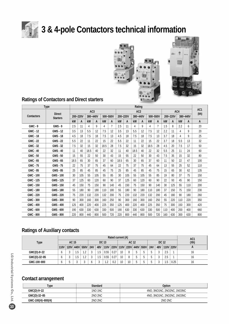
Rated current (A) AC1AC 15 DC 13 AC 12 DC 12 ( Ith)
110V 120V 440V 550V 24V 48V 110V 220V 110V 220V 440V 550V 24V 48V 110V 220V A
6 3 1.5 1.2 3 1.5 0.55 0.27 10 8 5 5 5 3 2.5 1 16
6 3 1.5 1.2 3 1.5 0.55 0.27 10 8 5 5 5 3 2.5 1 16
6 5 3 3 6 3 1.2 0.2 10 10 5 5 5 3 1.5 0.25 16
Type
GMC(D)-9~22
GMC(D)-32~85
GMC-100~800
Type Standard Option
GMC(D)-9~22 1NO 1NC 4NO, 3NO1NC, 2NO2NC, 1NO3NC
GMC(D)-32~85 2NO 2NC 4NO, 3NO1NC, 2NO2NC, 1NO3NC
GMC-100(/4)~800(/4) 2NO 2NC 2NO 2NC
Ratings of Auxiliary contacts
Contact arrangement
3 & 4-pole Contactors technical information
Rating
AC3 AC2 AC4 AC1
200~220V 380~440V 500~550V 200~220V 380~440V 500~550V 200~220V 380~440V(Ith)
kW A kW A kW A kW A kW A kW A kW A kW A A
2.5 11 4 9 4 7 2.5 11 4 9 4 7 1.5 8 2.2 6 20
3.5 13 5.5 12 7.5 12 3.5 13 5.5 12 7.5 12 2.2 11 4 9 20
4.5 18 7.5 18 7.5 13 4.5 18 7.5 18 7.5 13 3.7 18 4 9 25
5.5 22 11 22 15 22 5.5 22 11 22 15 22 3.7 18 5.5 13 32
7.5 32 15 32 18.5 28 7.5 32 15 32 18.5 28 4.5 20 7.5 17 50
11 40 18.5 40 22 32 11 40 18.5 40 22 32 5.5 25 11 24 60
15 55 22 50 30 43 15 55 22 50 30 43 7.5 35 15 32 80
18.5 65 30 65 37 60 18.5 65 30 65 37 60 11 50 22 47 100
22 75 37 75 45 64 22 75 37 75 45 64 13 55 25 52 110
25 85 45 85 45 75 25 85 45 85 45 75 15 65 30 62 135
30 105 55 105 55 85 30 105 55 105 55 85 19 80 37 75 150
37 125 60 120 60 90 37 125 60 120 60 90 22 93 45 90 150
45 150 75 150 90 140 45 150 75 150 90 140 30 125 55 110 200
55 180 90 180 110 180 55 180 90 180 110 180 37 150 75 150 230
75 220 132 220 132 200 75 220 132 220 132 200 45 180 90 180 260
90 300 160 300 160 250 90 300 160 300 160 250 55 220 110 220 350
125 400 220 400 225 350 125 400 220 400 225 350 75 300 150 300 420
190 630 330 630 330 500 190 630 330 630 330 500 110 400 200 400 660
220 800 440 800 500 720 220 800 440 800 500 720 160 630 300 630 800
Type
DirectContactors Starters
GMC - 9 GMS - 9
GMC - 12 GMS - 12
GMC - 18 GMS - 18
GMC - 22 GMS - 22
GMC - 32 GMS - 32
GMC - 40 GMS - 40
GMC - 50 GMS - 50
GMC - 65 GMS - 65
GMC - 75 GMS - 75
GMC - 85 GMS - 85
GMC - 100 GMS - 100
GMC - 125 GMS - 125
GMC - 150 GMS - 150
GMC - 180 GMS - 180
GMC - 220 GMS - 220
GMC - 300 GMS - 300
GMC - 400 GMS - 400
GMC - 600 GMS - 600
GMC - 800 GMS - 800
Ratings of Contactors and Direct starters
M E T A - M E C S E R I E S
11
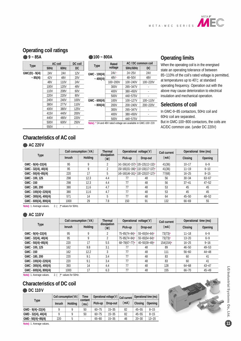
Coil consumption ((VA)) Time Operational voltage ((V)) Coil current Operational time (ms)Type
Inrush Holdingcontant
Pick-up Drop-out ((mA)) Closing Opening((ms))
GMD - 9(/4)~22(/4) 9 9 50 60~75 15~35 82 45~55 8~15GMD - 32(/4), 40(/4) 9 9 50 60~75 15~35 82 45~55 8~15GMD - 50(/4)~85(/4) 220 5 - 65~80 15~35 46 20~30 13~20
AC 220VCoil consumption ((VA)) Thermal Operational voltage ((V)) Coil current Operational time (ms)
TypeInrush Holding
dissipationPick-up Drop-out ((mA)) Closing Opening((W))
GMC - 9(/4)~22(/4) 95 9 2 141~156(142~157)* 105~125(112~132)* 41(36) 10~17 6~9GMC - 32(/4), 40(/4) 95 9 2 150~165(151~166)* 110~130(117~137)* 41(36) 11~19 6~10GMC - 50(/4)~85(/4) 220 17 5 145~160(146~161)* 100~120(107~127)* 77(68) 16~25 8~15GMC - 100, 125 298 12.3 4.4 77 48 56 30~34 63~67GMC - 150 298 12.3 4.4 77 48 56 37~41 47~52GMC - 180, 200 380 11.6 4.7 77 48 53 45 45GMC - 100(/4)~220(/4) 380 11.6 4.7 77 48 53 45 45GMC - 300(/4), 400(/4) 571 14 5 77 48 64 45~50 48~52GMC - 600(/4), 800(/4) 1000 29 7.8 150 91 132 66~69 55
Coil consumption ((VA)) Thermal Operational voltage ((V)) Coil current Operational time (ms)Type
Inrush Holdingdissipation
Pick-up Drop-out ((mA)) Closing Opening((W))
GMC - 9(/4)~22(/4) 95 9 2 75~85(74~84)* 55~65(54~64)* 73(73)* 11~18 6~9GMC - 32(/4), 40(/4) 95 9 2 75~85(74~84)* 55~65(54~64)* 73(73)* 13~20 6~9GMC - 50(/4)~85(/4) 220 17 5.5 68~78(67~77)* 40~50(39~49)* 154(154)* 16~25 9~16GMC - 100, 125 162 9.8 3.1 77 48 89 46~50 49~53GMC - 150 162 12.2 3 77 48 111 56~60 44~48GMC - 180, 200 220 9.1 3.4 77 48 83 60 41GMC - 100(/4)~220(/4) 220 9.1 3.4 77 48 83 60 41GMC - 300(/4), 400(/4) 393 14 4.4 77 48 128 64~68 43~47GMC - 600(/4), 800(/4) 1000 17 6.3 77 48 155 66~70 45~49
Characteristics of AC coil
Type AC coil DC coil50Hz 60Hz DC
GMC(D) - 9(/4) 24V 24V 12V~ 85(/4) 42V 48V 20V
48V 110V 24V100V 120V 48V110V 208V 60V 220V 220V 80V240V 240V 100V 380V 277V 110V 400V 380V 125V415V 440V 200V 440V 480V 220V 500V 600V 250V 550V - -
Type Rated AC / DC common coilvoltage 50Hz/60Hz DC
GMC - 100(/4) 24V * 24~25V 24V
~ 400(/4) 48V * 48~50V 48V100~200V 100~240V 100~220V
300V 265~347V -400V 380~450V -500V 440~575V -
GMC - 600(/4) 100V 100~127V 100~110V~ 800(/4) 200V 200~240V 200~220V
300V 265~347V -400V 380~450V -500V 440~575V
Operating limitsWhen the operating coil is in the energisedstate an operating tolerance of between85~110% of the coil’s rated voltage is permitted,at temperatures up to 40℃ at standardoperating frequency. Operation out with theabove may cause deterioration to electricalinsulation and mechanical operation.
Selections of coilIn GMC-9~85 contactors, 50Hz coil and 60Hz coil are separated.But in GMC-100~800 contactors, the coils areAC/DC common use. (under DC 220V)
Note) * 24 and 48V rated voltage are available in GMC-100~220
Operating coil ratings
Characteristics of DC coil
9 ~ 85A 100 ~ 800A
AC 110V
DC 110V
Note) 1. Average values. 2. ( )* values for 50Hz.
Note) 1. Average values. 2. ( )* values for 50Hz.
Note) 1. Average values.
12
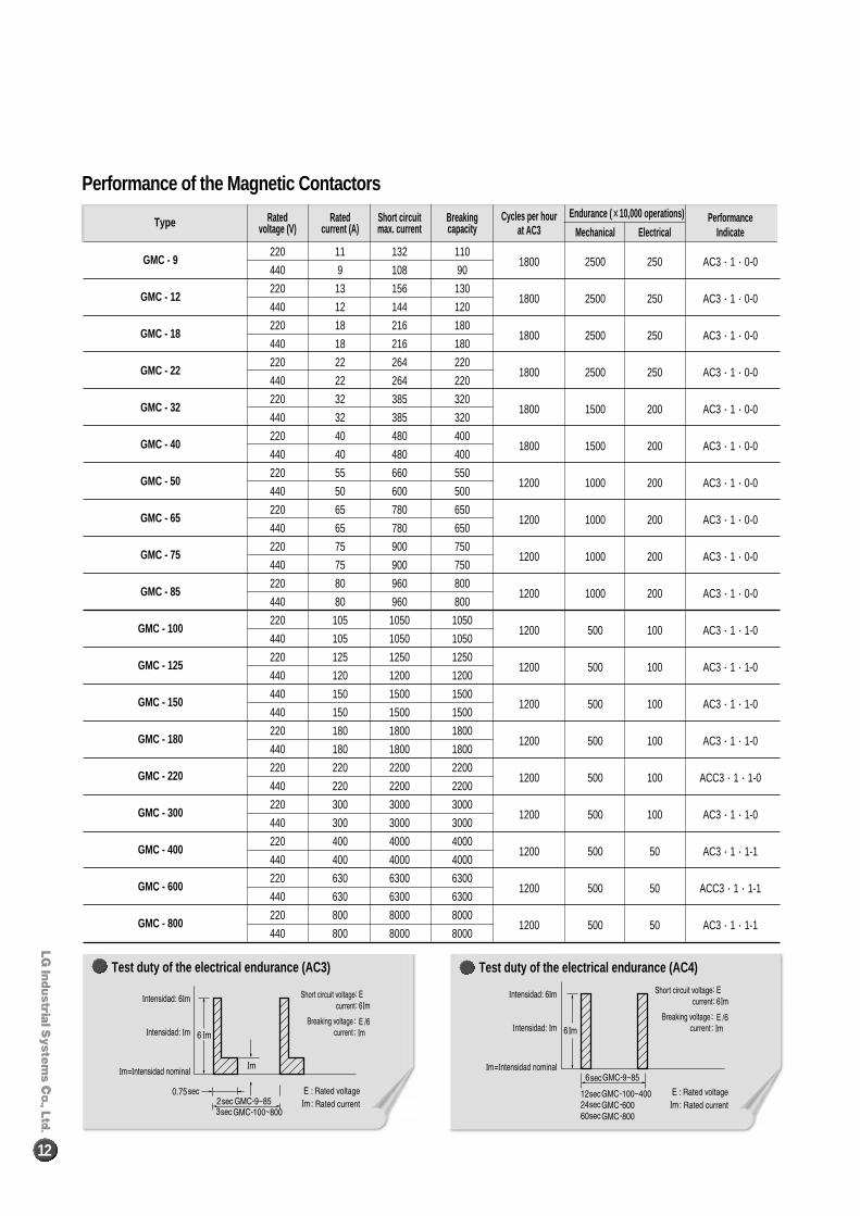
Test duty of the electrical endurance (AC3) Test duty of the electrical endurance (AC4)
Performance of the Magnetic Contactors
Rated Rated Short circuit Breaking Cycles per hour Endurance ( ××10,000 operations) Performancevoltage (V) current (A) max. current capacity at AC3 Mechanical Electrical Indicate
220 11 132 1101800 2500 250 AC3∙1∙0-0
440 9 108 90
220 13 156 1301800 2500 250 AC3∙1∙0-0
440 12 144 120
220 18 216 1801800 2500 250 AC3∙1∙0-0
440 18 216 180
220 22 264 2201800 2500 250 AC3∙1∙0-0
440 22 264 220
220 32 385 3201800 1500 200 AC3∙1∙0-0
440 32 385 320
220 40 480 4001800 1500 200 AC3∙1∙0-0
440 40 480 400
220 55 660 5501200 1000 200 AC3∙1∙0-0
440 50 600 500
220 65 780 6501200 1000 200 AC3∙1∙0-0
440 65 780 650
220 75 900 7501200 1000 200 AC3∙1∙0-0
440 75 900 750
220 80 960 8001200 1000 200 AC3∙1∙0-0
440 80 960 800
220 105 1050 10501200 500 100 AC3∙1∙1-0
440 105 1050 1050
220 125 1250 12501200 500 100 AC3∙1∙1-0
440 120 1200 1200
440 150 1500 15001200 500 100 AC3∙1∙1-0
440 150 1500 1500
220 180 1800 18001200 500 100 AC3∙1∙1-0
440 180 1800 1800
220 220 2200 22001200 500 100 ACC3∙1∙1-0
440 220 2200 2200
220 300 3000 30001200 500 100 AC3∙1∙1-0
440 300 3000 3000
220 400 4000 40001200 500 50 AC3∙1∙1-1
440 400 4000 4000
220 630 6300 63001200 500 50 ACC3∙1∙1-1
440 630 6300 6300
220 800 8000 80001200 500 50 AC3∙1∙1-1
440 800 8000 8000
Type
GMC - 9
GMC - 12
GMC - 18
GMC - 22
GMC - 32
GMC - 40
GMC - 50
GMC - 65
GMC - 75
GMC - 85
GMC - 100
GMC - 125
GMC - 150
GMC - 180
GMC - 220
GMC - 300
GMC - 400
GMC - 600
GMC - 800
M E T A - M E C S E R I E S
13
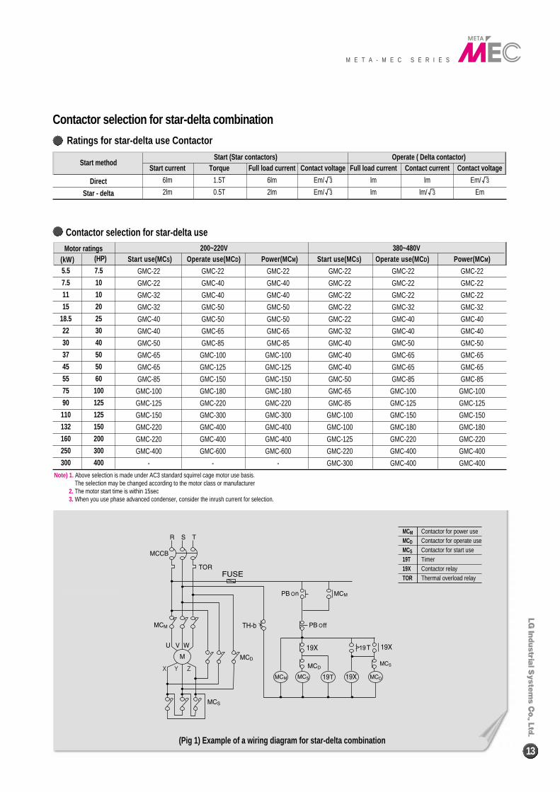
200~220V 380~480VStart use(MC S) Operate use(MC D) Power(MC M) Start use(MC S) Operate use(MC D) Power(MC M)
GMC-22 GMC-22 GMC-22 GMC-22 GMC-22 GMC-22
GMC-22 GMC-40 GMC-40 GMC-22 GMC-22 GMC-22
GMC-32 GMC-40 GMC-40 GMC-22 GMC-22 GMC-22
GMC-32 GMC-50 GMC-50 GMC-22 GMC-32 GMC-32
GMC-40 GMC-50 GMC-50 GMC-22 GMC-40 GMC-40
GMC-40 GMC-65 GMC-65 GMC-32 GMC-40 GMC-40
GMC-50 GMC-85 GMC-85 GMC-40 GMC-50 GMC-50
GMC-65 GMC-100 GMC-100 GMC-40 GMC-65 GMC-65
GMC-65 GMC-125 GMC-125 GMC-40 GMC-65 GMC-65
GMC-85 GMC-150 GMC-150 GMC-50 GMC-85 GMC-85
GMC-100 GMC-180 GMC-180 GMC-65 GMC-100 GMC-100
GMC-125 GMC-220 GMC-220 GMC-85 GMC-125 GMC-125
GMC-150 GMC-300 GMC-300 GMC-100 GMC-150 GMC-150
GMC-220 GMC-400 GMC-400 GMC-100 GMC-180 GMC-180
GMC-220 GMC-400 GMC-400 GMC-125 GMC-220 GMC-220
GMC-400 GMC-600 GMC-600 GMC-220 GMC-400 GMC-400
- - - GMC-300 GMC-400 GMC-400
Motor ratings(kW) (HP)
5.5 7.5
7.5 10
11 10
15 20
18.5 25
22 30
30 40
37 50
45 50
55 60
75 100
90 125
110 125
132 150
160 200
250 300
300 400
Contactor selection for star-delta use
Start (Star contactors) Operate ( Delta contactor)Start current Torque Full load current Contact voltage Full load current Contact current Contact voltage
6lm 1.5T 6lm Em/√3 lm lm Em/√3
2lm 0.5T 2lm Em/√3 lm lm/√3 Em
Start method
Direct
Star - delta
MCM Contactor for power useMCD Contactor for operate useMCS Contactor for start use19T Timer19X Contactor relayTOR Thermal overload relay
Contactor selection for star-delta combination
Ratings for star-delta use Contactor
Note) 1. Above selection is made under AC3 standard squirrel cage motor use basis.The selection may be changed according to the motor class or manufacturer
2. The motor start time is within 15sec3. When you use phase advanced condenser, consider the inrush current for selection.
(Pig 1) Example of a wiring diagram for star-delta combination
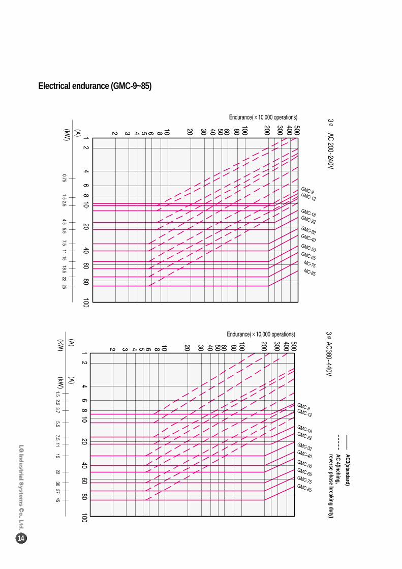
AC3(standard)
AC 4(Inching,reverse phase breaking duty)
14
Electrical endurance (GMC-9~85)
M E T A - M E C S E R I E S
15
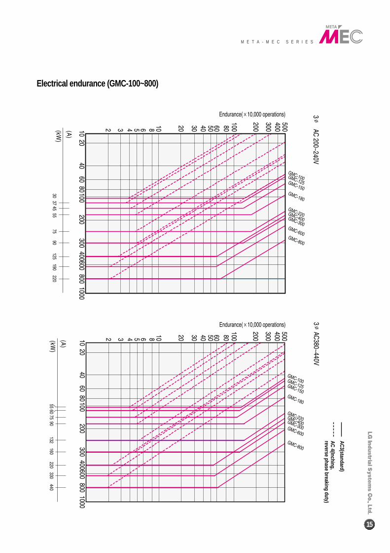
Electrical endurance (GMC-100~800)
AC3(standard)
AC 4(Inching,reverse phase breaking duty)
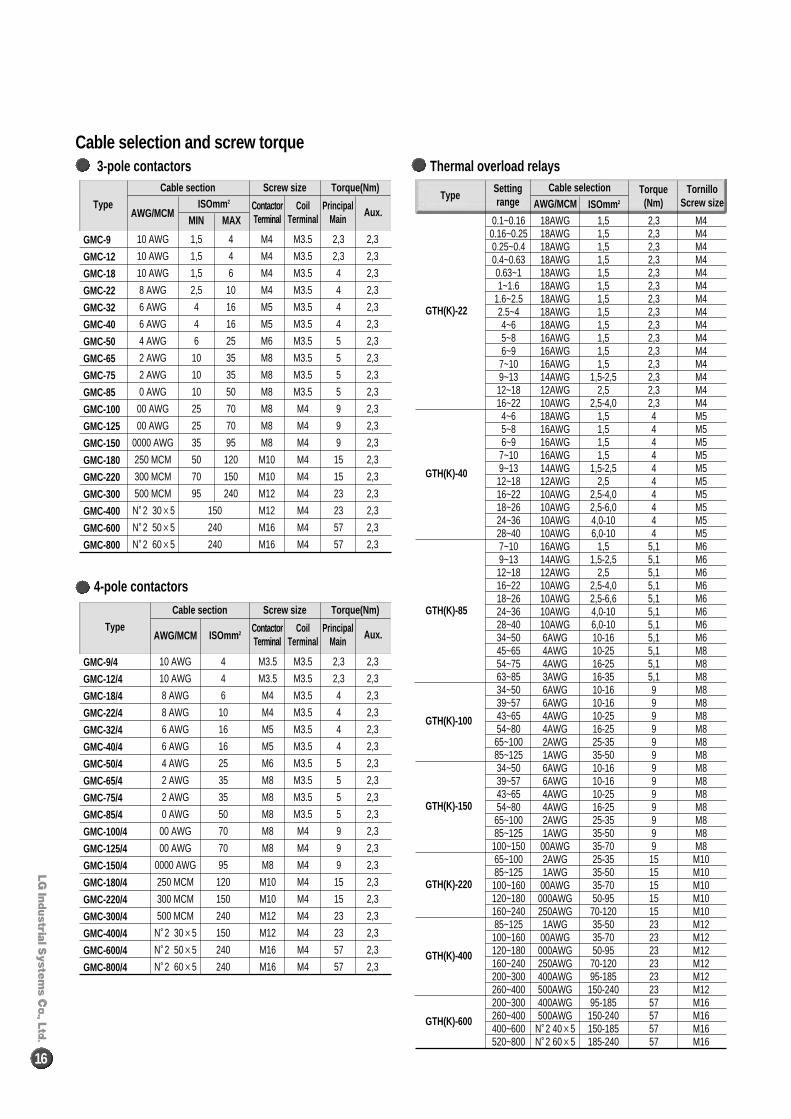
Cable selection and screw torque
16
3-pole contactors
10 AWG 1,5 4 M4 M3.5 2,3 2,3
10 AWG 1,5 4 M4 M3.5 2,3 2,3
10 AWG 1,5 6 M4 M3.5 4 2,3
8 AWG 2,5 10 M4 M3.5 4 2,3
6 AWG 4 16 M5 M3.5 4 2,3
6 AWG 4 16 M5 M3.5 4 2,3
4 AWG 6 25 M6 M3.5 5 2,3
2 AWG 10 35 M8 M3.5 5 2,3
2 AWG 10 35 M8 M3.5 5 2,3
0 AWG 10 50 M8 M3.5 5 2,3
00 AWG 25 70 M8 M4 9 2,3
00 AWG 25 70 M8 M4 9 2,3
0000 AWG 35 95 M8 M4 9 2,3
250 MCM 50 120 M10 M4 15 2,3
300 MCM 70 150 M10 M4 15 2,3
500 MCM 95 240 M12 M4 23 2,3
N�2 30×5 150 M12 M4 23 2,3
N�2 50×5 240 M16 M4 57 2,3
N�2 60×5 240 M16 M4 57 2,3
GMC-9
GMC-12
GMC-18
GMC-22
GMC-32
GMC-40
GMC-50
GMC-65
GMC-75
GMC-85
GMC-100
GMC-125
GMC-150
GMC-180
GMC-220
GMC-300
GMC-400
GMC-600
GMC-800
Type
Cable section
AWG/MCMISOmm 2 Contactor
TerminalCoil
TerminalPrincipal
MainAux.
MIN MAX
Screw size Torque(Nm)
Thermal overload relays
0.1~0.16 18AWG 1,5 2,3 M40.16~0.25 18AWG 1,5 2,3 M40.25~0.4 18AWG 1,5 2,3 M40.4~0.63 18AWG 1,5 2,3 M40.63~1 18AWG 1,5 2,3 M41~1.6 18AWG 1,5 2,3 M4
1.6~2.5 18AWG 1,5 2,3 M42.5~4 18AWG 1,5 2,3 M44~6 18AWG 1,5 2,3 M45~8 16AWG 1,5 2,3 M46~9 16AWG 1,5 2,3 M4
7~10 16AWG 1,5 2,3 M49~13 14AWG 1,5-2,5 2,3 M4
12~18 12AWG 2,5 2,3 M416~22 10AWG 2,5-4,0 2,3 M44~6 18AWG 1,5 4 M55~8 16AWG 1,5 4 M56~9 16AWG 1,5 4 M5
7~10 16AWG 1,5 4 M59~13 14AWG 1,5-2,5 4 M5
12~18 12AWG 2,5 4 M516~22 10AWG 2,5-4,0 4 M518~26 10AWG 2,5-6,0 4 M524~36 10AWG 4,0-10 4 M528~40 10AWG 6,0-10 4 M57~10 16AWG 1,5 5,1 M69~13 14AWG 1,5-2,5 5,1 M6
12~18 12AWG 2,5 5,1 M616~22 10AWG 2,5-4,0 5,1 M618~26 10AWG 2,5-6,6 5,1 M624~36 10AWG 4,0-10 5,1 M628~40 10AWG 6,0-10 5,1 M634~50 6AWG 10-16 5,1 M645~65 4AWG 10-25 5,1 M854~75 4AWG 16-25 5,1 M863~85 3AWG 16-35 5,1 M834~50 6AWG 10-16 9 M839~57 6AWG 10-16 9 M843~65 4AWG 10-25 9 M854~80 4AWG 16-25 9 M8
65~100 2AWG 25-35 9 M885~125 1AWG 35-50 9 M834~50 6AWG 10-16 9 M839~57 6AWG 10-16 9 M843~65 4AWG 10-25 9 M854~80 4AWG 16-25 9 M8
65~100 2AWG 25-35 9 M885~125 1AWG 35-50 9 M8
100~150 00AWG 35-70 9 M865~100 2AWG 25-35 15 M1085~125 1AWG 35-50 15 M10
100~160 00AWG 35-70 15 M10120~180 000AWG 50-95 15 M10160~240 250AWG 70-120 15 M1085~125 1AWG 35-50 23 M12
100~160 00AWG 35-70 23 M12120~180 000AWG 50-95 23 M12160~240 250AWG 70-120 23 M12200~300 400AWG 95-185 23 M12260~400 500AWG 150-240 23 M12200~300 400AWG 95-185 57 M16260~400 500AWG 150-240 57 M16400~600 N�2 40×5 150-185 57 M16520~800 N�2 60×5 185-240 57 M16
GTH(K)-22
GTH(K)-40
GTH(K)-85
GTH(K)-100
GTH(K)-150
GTH(K)-220
GTH(K)-400
GTH(K)-600
TypeSettingrange AWG/MCM ISOmm 2
Torque(Nm)
Cable selection TornilloScrew size
4-pole contactors
10 AWG 4 M3.5 M3.5 2,3 2,3
10 AWG 4 M3.5 M3.5 2,3 2,3
8 AWG 6 M4 M3.5 4 2,3
8 AWG 10 M4 M3.5 4 2,3
6 AWG 16 M5 M3.5 4 2,3
6 AWG 16 M5 M3.5 4 2,3
4 AWG 25 M6 M3.5 5 2,3
2 AWG 35 M8 M3.5 5 2,3
2 AWG 35 M8 M3.5 5 2,3
0 AWG 50 M8 M3.5 5 2,3
00 AWG 70 M8 M4 9 2,3
00 AWG 70 M8 M4 9 2,3
0000 AWG 95 M8 M4 9 2,3
250 MCM 120 M10 M4 15 2,3
300 MCM 150 M10 M4 15 2,3
500 MCM 240 M12 M4 23 2,3
N�2 30×5 150 M12 M4 23 2,3
N�2 50×5 240 M16 M4 57 2,3
N�2 60×5 240 M16 M4 57 2,3
GMC-9/4
GMC-12/4
GMC-18/4
GMC-22/4
GMC-32/4
GMC-40/4
GMC-50/4
GMC-65/4
GMC-75/4
GMC-85/4
GMC-100/4
GMC-125/4
GMC-150/4
GMC-180/4
GMC-220/4
GMC-300/4
GMC-400/4
GMC-600/4
GMC-800/4
Type
Cable section
AWG/MCM ISOmm 2ContactorTerminal
CoilTerminal
PrincipalMain
Aux.
Screw size Torque(Nm)
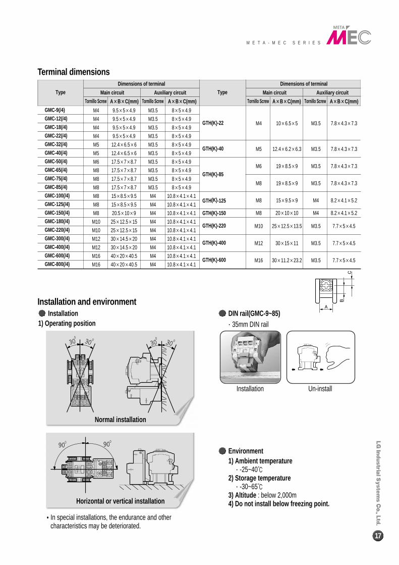
Terminal dimensions
M E T A - M E C S E R I E S
17
Installation and environmentInstallation
Dimensions of terminal
Main circuit
Tornillo Screw Tornillo ScrewA××B××C(mm) A××B××C(mm)
Auxiliary circuit
Dimensions of terminal
Main circuit
Tornillo Screw Tornillo ScrewA××B××C(mm) A××B××C(mm)
Auxiliary circuitType Type
GMC-9(/4)
GMC-12(/4)
GMC-18(/4)
GMC-22(/4)
GMC-32(/4)
GMC-40(/4)
GMC-50(/4)
GMC-65(/4)
GMC-75(/4)
GMC-85(/4)
GMC-100(/4)
GMC-125(/4)
GMC-150(/4)
GMC-180(/4)
GMC-220(/4)
GMC-300(/4)
GMC-400(/4)
GMC-600(/4)
GMC-800(/4)
M4 9.5×5×4.9 M3.5 8×5×4.9
M4 9.5×5×4.9 M3.5 8×5×4.9
M4 9.5×5×4.9 M3.5 8×5×4.9
M4 9.5×5×4.9 M3.5 8×5×4.9
M5 12.4×6.5×6 M3.5 8×5×4.9
M5 12.4×6.5×6 M3.5 8×5×4.9
M6 17.5×7×8.7 M3.5 8×5×4.9
M8 17.5×7×8.7 M3.5 8×5×4.9
M8 17.5×7×8.7 M3.5 8×5×4.9
M8 17.5×7×8.7 M3.5 8×5×4.9
M8 15×8.5×9.5 M4 10.8×4.1×4.1
M8 15×8.5×9.5 M4 10.8×4.1×4.1
M8 20.5×10×9 M4 10.8×4.1×4.1
M10 25×12.5×15 M4 10.8×4.1×4.1
M10 25×12.5×15 M4 10.8×4.1×4.1
M12 30×14.5×20 M4 10.8×4.1×4.1
M12 30×14.5×20 M4 10.8×4.1×4.1
M16 40×20×40.5 M4 10.8×4.1×4.1
M16 40×20×40.5 M4 10.8×4.1×4.1
M4 10×6.5×5 M3.5 7.8×4.3×7.3
M5 12.4×6.2×6.3 M3.5 7.8×4.3×7.3
M6 19×8.5×9 M3.5 7.8×4.3×7.3
M8 19×8.5×9 M3.5 7.8×4.3×7.3
M8 15×9.5×9 M4 8.2×4.1×5.2
M8 20×10×10 M4 8.2×4.1×5.2
M10 25×12.5×13.5 M3.5 7.7×5×4.5
M12 30×15×11 M3.5 7.7×5×4.5
M16 30×11.2×23.2 M3.5 7.7×5×4.5
GTH(K)-22
GTH(K)-40
GTH(K)-85
GTH(K)-125
GTH(K)-150
GTH(K)-220
GTH(K)-400
GTH(K)-600
1) Operating position
Environment1) Ambient temperature
∙-25~40℃2) Storage temperature
∙-30~65℃3) Altitude : below 2,000m4) Do not install below freezing point.
DIN rail(GMC-9~85)∙35mm DIN rail
Installation Un-install
�In special installations, the endurance and othercharacteristics may be deteriorated.
Normal installation
Horizontal or vertical installation
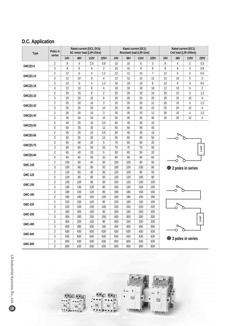
D.C. Application
18
2 poles in series
3 poles in series
Rated current (DC2, DC4)DC motor load (L/R=15ms)
Rated current (DC1)Resistant load (L/R=1ms)
Rated current (DC1)Coil load (L/R=100ms)Type
Poles inseries
GMC(D)-9
GMC(D)-12
GMC(D)-18
GMC(D)-22
GMC(D)-32
GMC(D)-40
GMC(D)-50
GMC(D)-65
GMC(D)-75
GMC(D)-85
GMC-100
GMC-125
GMC-150
GMC-180
GMC-220
GMC-300
GMC-400
GMC-600
GMC-800
2
3
2
3
2
3
2
3
2
3
2
3
2
3
2
3
2
3
2
3
2
3
2
3
2
3
2
3
2
3
2
3
2
3
2
3
2
3
8 4 2.5 0.8
8 6 4 2
12 6 4 1.2
12 10 8 4
12 6 4 1.2
12 10 8 4
20 15 8 2
20 20 15 8
25 20 10 3
25 25 20 10
35 20 10 3
35 30 20 10
45 25 15 3.5
50 35 30 12
45 25 15 3.5
50 35 30 12
65 40 20 5
80 60 50 20
65 40 20 5
80 60 50 20
100 60 40 30
100 90 80 50
120 60 40 30
120 90 80 50
150 100 80 60
150 130 120 80
180 150 120 80
180 180 150 100
220 150 120 80
220 220 150 100
300 200 150 90
300 280 200 150
400 200 150 90
400 280 200 150
630 630 630 630
630 630 630 630
800 630 630 630
800 630 630 630
24V 48V 110V 220V 24V 48V 110V 220V 24V 48V 110V 220V
10 10 6 3
10 10 8 8
12 12 10 7
12 12 12 12
18 18 13 8
18 18 18 18
20 20 15 10
20 20 20 20
25 25 25 12
25 25 25 22
35 35 25 12
35 35 35 30
50 40 35 15
50 50 50 40
50 40 35 15
65 65 65 50
75 65 50 20
75 75 75 55
80 65 50 20
80 80 80 60
100 100 80 50
100 100 100 80
120 100 80 50
120 120 100 80
150 120 100 100
150 150 150 150
180 180 150 150
180 180 180 180
220 180 150 150
220 220 220 220
300 240 200 200
300 300 300 300
400 240 200 200
400 400 400 300
630 630 630 630
630 630 630 630
800 800 630 630
800 800 800 800
8 4 2 0.3
8 6 3 0.8
12 6 3 0.5
12 10 5 2
12 6 3 0.5
12 10 5 2
20 12 3 1.2
20 15 10 4
25 15 4 1.2
25 25 12 4
35 15 4 1.2
35 25 12 4
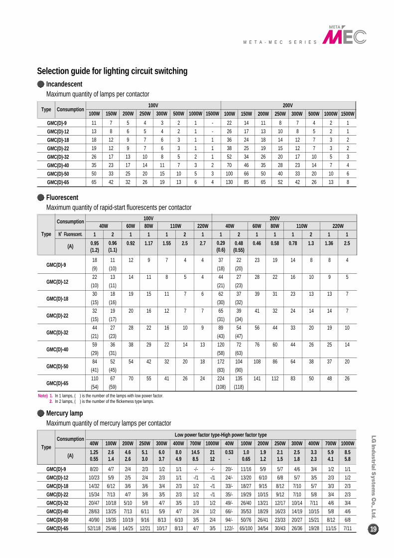
Selection guide for lighting circuit switching
M E T A - M E C S E R I E S
19
IncandescentMaximum quantity of lamps per contactor
11 7 5 4 3 2 1 -
13 8 6 5 4 2 1 -
18 12 9 7 6 3 1 1
19 12 9 7 6 3 1 1
26 17 13 10 8 5 2 1
35 23 17 14 11 7 3 2
50 33 25 20 15 10 5 3
65 42 32 26 19 13 6 4
22 14 11 8 7 4 2 1
26 17 13 10 8 5 2 1
36 24 18 14 12 7 3 2
38 25 19 15 12 7 3 2
52 34 26 20 17 10 5 3
70 46 35 28 23 14 7 4
100 66 50 40 33 20 10 6
130 85 65 52 42 26 13 8
100W100V 200V
Type Consumption150W 200W 250W 300W 500W 1000W 1500W 100W 150W 200W 250W 300W 500W 1000W 1500W
GMC(D)-9
GMC(D)-12
GMC(D)-18
GMC(D)-22
GMC(D)-32
GMC(D)-40
GMC(D)-50
GMC(D)-65
FluorescentMaximum quantity of rapid-start fluorescents per contactor
Mercury lampMaximum quantity of mercury lamps per contactor
18 11 12 9 7 4 4
(9) (10)
22 13 14 11 8 5 4
(10) (11)
30 18 19 15 11 7 6
(15) (16)
32 19 20 16 12 7 7
(15) (17)
44 27 28 22 16 10 9
(21) (23)
59 36 38 29 22 14 13
(29) (31)
84 52 54 42 32 20 18
(41) (45)
110 67 70 55 41 26 24
(54) (59)
37 22 23 19 14 8 8 4
(18) (20)
44 27 28 22 16 10 9 5
(21) (23)
62 37 39 31 23 13 13 7
(30) (32)
65 39 41 32 24 14 14 7
(31) (34)
89 54 56 44 33 20 19 10
(43) (47)
120 72 76 60 44 26 25 14
(58) (63)
172 104 108 86 64 38 37 20
(83) (90)
224 135 141 112 83 50 48 26
(108) (118)
GMC(D)-9
GMC(D)-12
GMC(D)-18
GMC(D)-22
GMC(D)-32
GMC(D)-40
GMC(D)-50
GMC(D)-65
GMC(D)-9
GMC(D)-12
GMC(D)-18
GMC(D)-22
GMC(D)-32
GMC(D)-40
GMC(D)-50
GMC(D)-65
Note) 1. In 1 lamps, ( ) is the number of the lamps with low power factor.2. In 2 lamps, ( ) is the number of the flickemess type lamps.
Consumption
Consumption
100V40W
40W
Low power factor type-High power factor type
1.250.55
2.61.4
4.62.6
5.13.0
6.03.7
8.04.9
14.58.5
2112
0.53-
1.00.65
1.91.2
2.11.5
2.51.8
3.32.3
5.94.1
8.55.8
100W 200W 250W 300W 400W 700W 1000W 40W 100W 200W 250W 300W 400W 700W 1000W
1 2 1 1 1 2 1 1 2 1 1 1 2 1 1
60W 80W 110W 220W 40W 60W 80W 110W 220W200V
N��Fluorescent.
(A)
(A)
Type
Type
0.95(1.2)
0.96(1.1)
0.92 1.17 1.55 2.5 2.7 0.29(0.6)
0.48(0.55)
0.46 0.58 0.78 1.3 1.36 2.5
8/20 4/7 2/4 2/3 1/2 1/1 -/- -/-
10/23 5/9 2/5 2/4 2/3 1/1 -/1 -/1
14/32 6/12 3/6 3/6 3/4 2/3 1/2 -/1
15/34 7/13 4/7 3/6 3/5 2/3 1/2 -/1
20/47 10/18 5/10 5/8 4/7 3/5 1/3 1/2
28/63 13/25 7/13 6/11 5/9 4/7 2/4 1/2
40/90 19/35 10/19 9/16 8/13 6/10 3/5 2/4
52/118 25/46 14/25 12/21 10/17 8/13 4/7 3/5
20/- 11/16 5/9 5/7 4/6 3/4 1/2 1/1
24/- 13/20 6/10 6/8 5/7 3/5 2/3 1/2
33/- 18/27 9/15 8/12 7/10 5/7 3/3 2/3
35/- 19/29 10/15 9/12 7/10 5/8 3/4 2/3
49/- 26/40 13/21 12/17 10/14 7/11 4/6 3/4
66/- 35/53 18/29 16/23 14/19 10/15 5/8 4/6
94/- 50/76 26/41 23/33 20/27 15/21 8/12 6/8
122/- 65/100 34/54 30/43 26/36 19/28 11/15 7/11
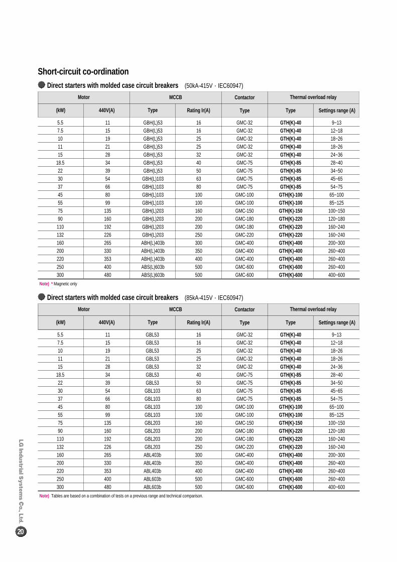
MCCB Contactor
Type Rating lr(A) Type Type Settings range (A)
Thermal overload relayMotor
(kW) 440V(A)
5.5 117.5 1510 1911 2115 28
18.5 3422 3930 5437 6645 8055 9975 13590 160
110 192132 226160 265200 330220 353250 400300 480
GMC-32GMC-32GMC-32GMC-32GMC-32GMC-75GMC-75GMC-75GMC-75
GMC-100GMC-100GMC-150GMC-180GMC-180GMC-220GMC-400GMC-400GMC-400GMC-600GMC-600
161625253240506380
100100160200200250300350400500500
GBL53GBL53GBL53GBL53GBL53GBL53GBL53
GBL103GBL103GBL103GBL103GBL203GBL203GBL203GBL203ABL403bABL403bABL403bABL603bABL603b
GTH(K)-40GTH(K)-40GTH(K)-40GTH(K)-40GTH(K)-40GTH(K)-85GTH(K)-85GTH(K)-85GTH(K)-85
GTH(K)-100GTH(K)-100GTH(K)-150GTH(K)-220GTH(K)-220GTH(K)-220GTH(K)-400GTH(K)-400GTH(K)-400GTH(K)-600GTH(K)-600
9~1312~1818~2618~2624~3628~4034~5045~6554~75
65~10085~125
100~150120~180160~240160~240200~300260~400260~400260~400400~600
Short-circuit co-ordination
20
Direct starters with molded case circuit breakers (85kA-415V∙IEC60947)
Note) Tables are based on a combination of tests on a previous range and technical comparison.
MCCB Contactor
Type Rating lr(A) Type Type Settings range (A)
Thermal overload relayMotor
(kW) 440V(A)
5.5 117.5 1510 1911 2115 28
18.5 3422 3930 5437 6645 8055 9975 13590 160
110 192132 226160 265200 330220 353250 400300 480
GMC-32GMC-32GMC-32GMC-32GMC-32GMC-75GMC-75GMC-75GMC-75
GMC-100GMC-100GMC-150GMC-180GMC-180GMC-220GMC-400GMC-400GMC-400GMC-600GMC-600
161625253240506380
100100160200200250300350400500500
GBH(L)53GBH(L)53GBH(L)53GBH(L)53GBH(L)53GBH(L)53GBH(L)53
GBH(L)103GBH(L)103GBH(L)103GBH(L)103GBH(L)203GBH(L)203GBH(L)203GBH(L)203ABH(L)403bABH(L)403bABH(L)403bABS(L)603bABS(L)603b
GTH(K)-40GTH(K)-40GTH(K)-40GTH(K)-40GTH(K)-40GTH(K)-85GTH(K)-85GTH(K)-85GTH(K)-85
GTH(K)-100GTH(K)-100GTH(K)-150GTH(K)-220GTH(K)-220GTH(K)-220GTH(K)-400GTH(K)-400GTH(K)-400GTH(K)-600GTH(K)-600
9~1312~1818~2618~2624~3628~4034~5045~6554~75
65~10085~125
100~150120~180160~240160~240200~300260~400260~400260~400400~600
Direct starters with molded case circuit breakers (50kA-415V∙IEC60947)
Note) * Magnetic only
M E T A - M E C S E R I E S
21
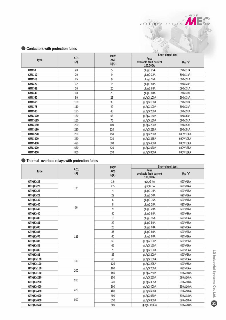
Contactors with protection fuses
Thermal overload relays with protection fuses
Contactors with protection fuses
GMC-9GMC-12GMC-18GMC-22GMC-32GMC-40GMC-50GMC-65GMC-75GMC-85GMC-100GMC-125GMC-150GMC-180GMC-220GMC-300GMC-400GMC-600GMC-800
20 520 925 932 1850 2060 2380 28
100 35110 42135 45150 65150 70200 100230 120260 150350 220420 300660 420800 630
gL/gG 25A 690V/1kAgL/gG 32A 690V/1kAgL/gG 35A 690V/3kAgL/gG 50A 690V/3kAgL/gG 63A 690V/3kAgL/gG 80A 690V/3kA
gL/gG 100A 690V/3kAgL/gG 100A 690V/3kAgL/gG 100A 690V/3kAgL/gG 200A 690V/3kAgL/gG 150A 690V/5kAgL/gG 160A 690V/5kAgL/gG 200A 690V/5kAgL/gG 225A 690V/5kAgL/gG 250A 690V/10kAgL/gG 355A 690V/10kAgL/gG 400A 690V/10kAgL/gG 630A 690V/18kAgL/gG 800A 690V/18kA
TypeAC1(A)
690VAC3le(A)
Fuseavailable fault current
100,000A
Short-circuit test
Ue / ““r””
GTH(K)-22GTH(K)-22GTH(K)-22GTH(K)-22GTH(K)-40GTH(K)-40GTH(K)-40GTH(K)-40GTH(K)-85GTH(K)-85GTH(K)-85GTH(K)-85GTH(K)-85GTH(K)-85GTH(K)-85GTH(K)-85GTH(K)-85GTH(K)-100GTH(K)-100GTH(K)-150GTH(K)-150GTH(K)-220GTH(K)-220GTH(K)-400GTH(K)-400GTH(K)-600GTH(K)-600GTH(K)-600
32
60
135
150
200
260
420
800
1.62.54
22689
4018222636405065758565
125100150150240300400400630800
gL/gG 4A 690V/1kAgL/gG 6A 690V/1kA
gL/gG 10A 690V/1kAgL/gG 50A 690V/3kAgL/gG 16A 690V/1kAgL/gG 20A 690V/1kAgL/gG 20A 690V/1kAgL/gG 80A 690V/3kAgL/gG 35A 690V/3kAgL/gG 50A 690V/3kAgL/gG 63A 690V/3kAgL/gG 80A 690V/3kAgL/gG 80A 690V/3kA
gL/gG 100A 690V/3kAgL/gG 160A 690V/5kAgL/gG 160A 690V/5kAgL/gG 200A 690V/5kAgL/gG 150A 690V/5kAgL/gG 225A 690V/5kAgL/gG 200A 690V/5kAgL/gG 250A 690V/10kAgL/gG 250A 690V/10kAgL/gG 355A 690V/10kAgL/gG 400A 690V/10kAgL/gG 630A 690V/18kAgL/gG 630A 690V/18kAgL/gG 800A 690V/18kA
gL/gG 1400A 690V/30kA
TypeAC1(A)
690VAC3le(A)
Fuseavailable fault current
100,000A
Short-circuit test
Ue / ““r””
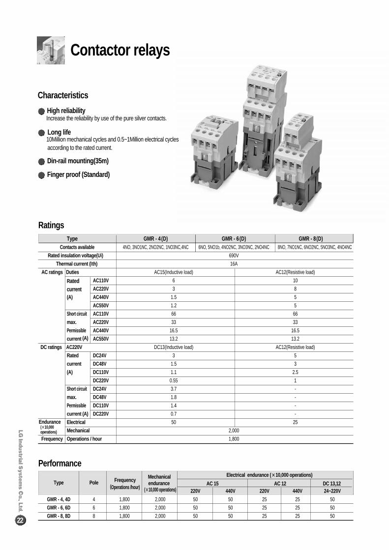
Contactor relays
22
Frequency Mechanical Electrical endurance ( ××10,000 operations)Type Pole
(Operations /hour) endurance AC 15 AC 12 DC 13,12
(××10,000 operations) 220V 440V 220V 440V 24~220V
GMR - 4, 4D 4 1,800 2,000 50 50 25 25 50
GMR - 6, 6D 6 1,800 2,000 50 50 25 25 50
GMR - 8, 8D 8 1,800 2,000 50 50 25 25 50
Characteristics
Ratings
Performance
Increase the reliability by use of the pure silver contacts.
10Million mechanical cycles and 0.5~1Million electrical cyclesaccording to the rated current.
High reliability
Long life
Din-rail mounting(35m)
Type GMR - 4 (D) GMR - 6 (D) GMR - 8(D)Contacts available 4NO, 3NO1NC, 2NO2NC, 1NO3NC,4NC 6NO, 5NO1b, 4NO2NC, 3NO3NC, 2NO4NC 8NO, 7NO1NC, 6NO2NC, 5NO3NC, 4NO4NC
Rated insulation voltage (Ui) 690V
Thermal current (Ith) 16A
AC ratings Duties AC15(Inductive load) AC12(Resistive load)
Rated AC110V 6 10
current AC220V 3 8
(A) AC440V 1.5 5
AC550V 1.2 5
Short circuit AC110V 66 66
max. AC220V 33 33
Permissible AC440V 16.5 16.5
current (A) AC550V 13.2 13.2
DC ratings AC220V DC13(Inductive load) AC12(Resistive load)
Rated DC24V 3 5
current DC48V 1.5 3
(A) DC110V 1.1 2.5
DC220V 0.55 1
Short circuit DC24V 3.7 -
max. DC48V 1.8 -
Permissible DC110V 1.4 -
current (A) DC220V 0.7 -
Electrical 50 25
Mechanical 2,000
Frequency Operations / hour 1,800
Finger proof (Standard)
Endurance(××10,000operations)
Coil consumption (VA) Operation voltage (V) Operation time (ms)Type
Inrush HoldingThermal
Pick-up Drop-outCoil ON �� Coil ON �� Coil OFF �� Coil OFF ��dissipation
NO contact ON NC contact OFF NO contact OFF NC contact ON
GMR - 44NO
(W)
141~156 105~125 10~17 ‐ 7~13 ‐
2NO2NC 138~148 110~130 8~15 6~15 7~13 8~15
GMR - 66NO 95 9 2 145~160 100~120 10~17 ‐ 7~13 ‐
3NO3NC 140~155 105~125 10~16 5~13 7~13 8~15
GMR - 68NO 150~160 90~110 10~18 ‐ 7~13 ‐
4NO4NC 148~158 95~115 10~16 5~13 7~13 8~15
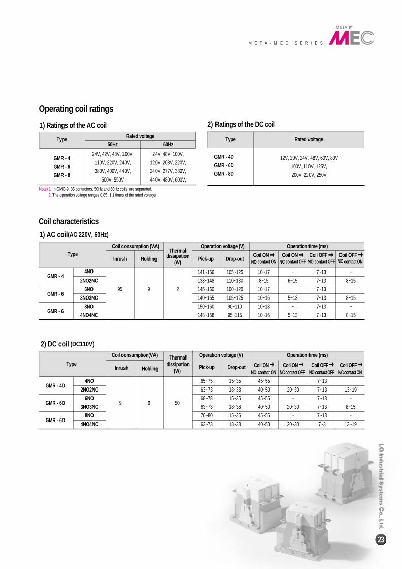
Type Rated voltage
GMR - 4
GMR - 6
GMR - 8
50Hz
24V, 42V, 48V, 100V,
110V, 220V, 240V,
380V, 400V, 440V,
500V, 550V
60Hz
24V, 48V, 100V,
120V, 208V, 220V,
240V, 277V, 380V,
440V, 480V, 600V,
1) Ratings of the AC coil
1) AC coil (AC 220V, 60Hz)
Note) 1. In GMC-9~85 contactors, 50Hz and 60Hz coils are separated.2. The operation voltage ranges 0.85~1.1 times of the rated voltage
Type Rated voltage
GMR - 4D
GMR - 6D
GMR - 8D
2) Ratings of the DC coil
Coil consumption(VA) Operation voltage (V) Operation time (ms)
TypeInrush Holding
Thermal
Pick-up Drop-out Coil ON �� Coil ON �� Coil OFF �� Coil OFF ��dissipationNO contact ON NC contact OFF NO contactOFF NCcontactON
GMR - 4D4NO
(W)
65~75 15~35 45~55 ‐ 7~13 ‐
2NO2NC 63~73 18~38 40~50 20~30 7~13 13~19
GMR - 6D6NO
9 9 5068~78 15~35 45~55 ‐ 7~13 ‐
3NO3NC 63~73 18~38 40~50 20~30 7~13 8~15
GMR - 6D8NO 70~80 15~35 45~55 ‐ 7~13 ‐
4NO4NC 63~73 18~38 40~50 20~30 7~3 13~19
2) DC coil (DC110V)
Operating coil ratings
Coil characteristics
12V, 20V, 24V, 48V, 60V, 80V
100V ,110V, 125V,
200V, 220V, 250V
M E T A - M E C S E R I E S
23
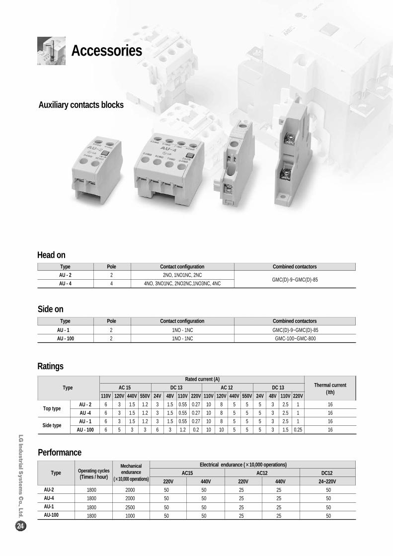
Type Pole Contact configuration Combined contactors
AU - 2 2 2NO, 1NO1NC, 2NCGMC(D)-9~GMC(D)-85
AU - 4 4 4NO, 3NO1NC, 2NO2NC,1NO3NC, 4NC
Type Pole Contact configuration Combined contactors
AU - 1 2 1NO - 1NC GMC(D)-9~GMC(D)-85
AU - 100 2 1NO - 1NC GMC-100~GMC-800
Head on
Side on
Auxiliary contacts blocks
Electrical endurance (××10,000 operations)Operating cycles AC15 AC12 DC12(Times / hour)
220V 440V 220V 440V 24~220V
1800 2000 50 50 25 25 50
1800 2000 50 50 25 25 50
1800 2500 50 50 25 25 50
1800 1000 50 50 25 25 50
Type
AU-2
AU-4
AU-1
AU-100
Performance
Ratings
Accessories
24
Rated current (A)Thermal currentAC 15 DC 13 AC 12 DC 13
( Ith) 110V 120V 440V 550V 24V 48V 110V 220V 110V 120V 440V 550V 24V 48V 110V 220V
6 3 1.5 1.2 3 1.5 0.55 0.27 10 8 5 5 5 3 2.5 1 16
6 3 1.5 1.2 3 1.5 0.55 0.27 10 8 5 5 5 3 2.5 1 16
6 3 1.5 1.2 3 1.5 0.55 0.27 10 8 5 5 5 3 2.5 1 16
6 5 3 3 6 3 1.2 0.2 10 10 5 5 5 3 1.5 0.25 16
Type
Top typeAU - 2
AU -4
Side typeAU - 1
AU - 100
Mechanicalendurance
(××10,000 operations)
M E T A - M E C S E R I E S
25
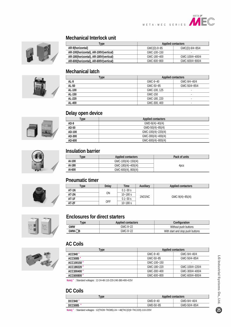
TypeAR-9(horizontal)AR-100(horizontal), AR-100V(vertical)AR-180(horizontal), AR-180V(vertical)AR-600(horizontal), AR-600V(vertical)
Applied contactors
Mechanical Interlock unit
TypeAL-9AL-50AL-100AL-150AL-220AL-400
Applied contactors
Mechanical latch
TypeACC940 **
ACC5085 **
ACC100150 **
ACC180220 **
ACC300400 **
ACC600800 **
Applied contactors
AC Coils
GMC-9~40 GMC-9/4~40/4GMC-50~85 GMC-50/4~85/4GMC-100~150 -GMC-180~220 GMC-100/4~220/4GMC-300~400 GMC-300/4~400/4GMC-600~800 GMC-600/4~800/4
GMC(D)-9~85 GMC(D)-9/4~85/4GMC-100~150 -GMC-180~400 GMC-100/4~400/4GMC-600~800 GMC-600/4~800/4
GMC-9~40 GMC-9/4~40/4GMC-50~85 GMC-50/4~85/4GMC-100, 125 -GMC-150 -GMC-180, 220 -GMC-300, 400 -
TypeAT-1NAT-2NAT-1FAT-2F
Delay Time Auxiliary Applied contactors
Pneumatic timer
GMC-9(/4)~85(/4)
TypeAI-100AI-180AI-600
Applied contactors Pack of units
Insulation barrier
4pcsGMC-100(/4)~150(/4)GMC-180(/4)~400(/4)GMC-600(/4), 800(/4)
0.1~30 s10~180 s0.1~30 s10~180 s
1NO1NC
TypeAD-9AD-50AD-100AD-300AD-600
Applied contactors
Delay open device
GMD-9(/4)~40(/4)GMD-50(/4)~85(/4)
GMC-100(/4)~220(/4)GMC-300(/4)~400(/4)GMC-600(/4)~800(/4)
TypeGMWGMW-��B
Applied contactors Configuration
Enclosures for direct starters
Without push buttonsWith start and stop push buttons
GMC-9~22GMC-9~22
Note) * : Standard voltages : 12-24-48-110-220-240-380-400-415V
TypeDCC940 **DCC5085 **
Applied contactors
DC Coils
GMD-9~40 GMD-9/4~40/4GMD-50~85 GMD-50/4~85/4
Note) * : Standard voltages : 12(TKD9~TKD85)-24 + 48(TKC(D)9~TKC220)-110-220V
ON
OFF
26
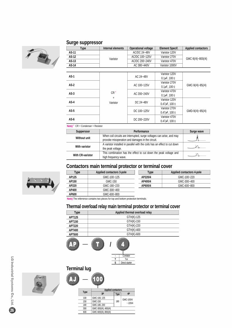
TypeAS-11AS-12AS-13AS-14
AS-1
AS-2
AS-3
AS-4
AS-5
AS-6
AC/DC 24~48V Varistor 120VAC/DC 100~125V Varistor 270VAC/DC 200~240V Varistor 470V
AC 380~440V Varistor 1000V
AC 24~48VVaristor 120V0.1μF, 100Ϊ
AC 100~125VVaristor 270V0.1μF, 100Ϊ
AC 200~240VVaristor 470V0.1μF, 100Ϊ
DC 24~48VVaristor 120V0.47μF, 100Ϊ
DC 100~125VVaristor 270V0.47μF, 100Ϊ
DC 200~220VVaristor 470V0.47μF, 100Ϊ
GMC-9(/4)~800(/4)
GMC-9(/4)~85(/4)
GMD-9(/4)~85(/4)
Varistor
CR *
+
Varistor
Internal elements Operational voltage Element Specif. Applied contactors
Surge suppressor
Note) * CR = Condenser + Resistor
Note) The referrence contains two pieces for top and bottom protection terminals.
Supperssor Performance Surge wave
Without unit
With varistor
With CR-varistor
When coil circuits are interrupted, surge voltages can arise, and mayprovoke misoperation and damages in the circuit.A varistor installed in parallel with the coils has an effect to cut downthe peak voltage.This combination has the effect to cut down the peak voltage andhigh frequency wave.
Type
AP125AP150AP220AP400AP600
GMC-100~125GMC-150
GMC-180~220GMC-300~400GMC-600~800
Applied contactors 3-pole Type
AP220/4AP400/4AP600/4
GMC-100~220GMC-300~400GMC-600~800
Applied contactors 4-pole
Contactors main terminal protector or terminal cover
Terminal lug
Type
APT125APT150APT220APT400APT600
GTH(K)-125GTH(K)-150GTH(K)-220GTH(K)-400GTH(K)-600
Applied thermal overload relay
Thermal overload relay main terminal protector or terminal cover
- ContatorT TorS Direct starter
AAPP //TT 44
AAJJ 110000
GMC-100/4~ 220/4
Type3P 4PType
100 GMC-100, 125150 GMC-150180 GMC-180, 200300 GMC-300(/4), 400(/4)600 GMC-600(/4), 800(/4)
180
Applied contactors
Reversing contactors M E T A - M E C S E R I E S
27
DirectRated power (kW) Rated current (A) Ith
Auxiliary contacts C ombined TORContactors
starters(AC3) (AC3) AC1
200~220V 380~440V 500~550V 200~220V 380~440V 500~550V (A) Standard Option Type Range (A)
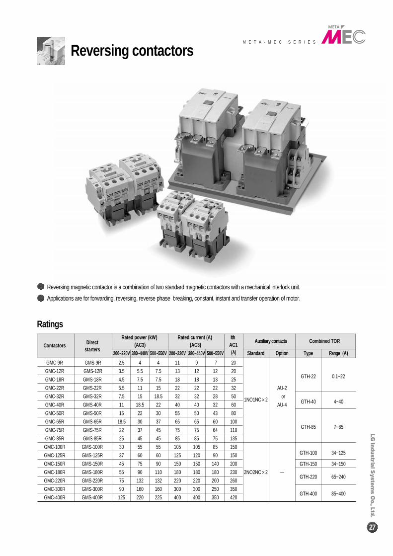
GMC-9R GMS-9R 2.5 4 4 11 9 7 20
GMC-12R GMS-12R 3.5 5.5 7.5 13 12 12 20GTH-22 0.1~22GMC-18R GMS-18R 4.5 7.5 7.5 18 18 13 25
GMC-22R GMS-22R 5.5 11 15 22 22 22 32 AU-2
GMC-32R GMS-32R 7.5 15 18.5 32 32 28 501NO1NC×2
orGTH-40 4~40GMC-40R GMS-40R 11 18.5 22 40 40 32 60 AU-4
GMC-50R GMS-50R 15 22 30 55 50 43 80
GMC-65R GMS-65R 18.5 30 37 65 65 60 100GTH-85 7~85GMC-75R GMS-75R 22 37 45 75 75 64 110
GMC-85R GMS-85R 25 45 45 85 85 75 135
GMC-100R GMS-100R 30 55 55 105 105 85 150GTH-100 34~125GMC-125R GMS-125R 37 60 60 125 120 90 150
GTH-150 34~150GMC-150R GMS-150R 45 75 90 150 150 140 200
GMC-180R GMS-180R 55 90 110 180 180 180 230 2NO2NC×2 ─GTH-220 65~240
GMC-220R GMS-220R 75 132 132 220 220 200 260
GMC-300R GMS-300R 90 160 160 300 300 250 350GTH-400 85~400
GMC-400R GMS-400R 125 220 225 400 400 350 420
Ratings
Reversing magnetic contactor is a combination of two standard magnetic contactors with a mechanical interlock unit.
Applications are for forwarding, reversing, reverse phase breaking, constant, instant and transfer operation of motor.
28
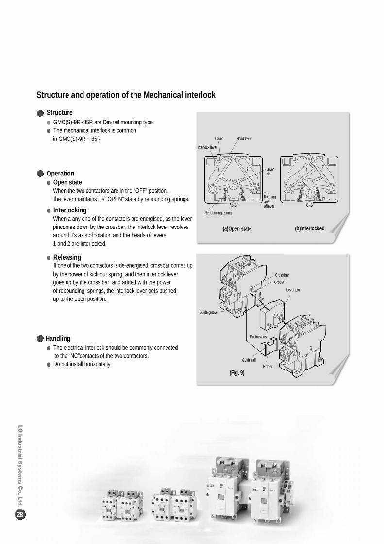
� GMC(S)-9R~85R are Din-rail mounting type� The mechanical interlock is common
in GMC(S)-9R ~ 85R
� Open stateWhen the two contactors are in the “OFF” position,the lever maintains it’s “OPEN” state by rebounding springs.
� InterlockingWhen a any one of the contactors are energised, as the leverpincomes down by the crossbar, the interlock lever revolvesaround it’s axis of rotation and the heads of levers 1 and 2 are interlocked.
� ReleasingIf one of the two contactors is de-energised, crossbar comes upby the power of kick out spring, and then interlock lever goes up by the cross bar, and added with the power of rebounding springs, the interlock lever gets pushed up to the open position.
Structure
� The electrical interlock should be commonly connected to the “NC”contacts of the two contactors.
� Do not install horizontally
Handling
Operation
Structure and operation of the Mechanical interlock
Cover
Leverpin
Head lever
Interlock lever
1 12 2
Rebounding spring
Rotatingaxisof lever
(a)Open state
(Fig. 9)
(b)Interlocked
Cross bar
Groove
Lever pin
Protrusions
HolderGuide rail
Guide groove
Latching contactorsM E T A - M E C S E R I E S
29
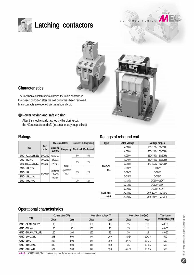
The mechanical latch unit maintains the main contacts inthe closed condition after the coil power has been removed.Main contacts are opened via the rebound coil.
Note) 1. AC220V, 60Hz The operational times are the average values after coil is energized
Aux.Close and Open Endurance( ××10,000 operations)
Type contact Breaking Frequency Electrical Mechanicalcurrent
GMC - 9L,12L,18L,22L 1NO1NC 10 times 50 50
GMC - 32L,40L 2NO2NC of AC3 25 25
GMC - 50L,65L,75L,85L 1NO2NC ratings
GMC - 100L,125L10 times
1200
GMC - 150L1NO2NC of AC3
Operations25 25
GMC - 180L,220L ratings
/hour
GMC - 300L,400L 20 20
Type Rated voltage Voltage ranges
AC100 100~127V 50/60Hz
AC200 200~240V 50/60Hz
AC300 260~350V 50/60Hz
AC400 380~440V 50/60Hz
GMC- 9LAC500 460~550V 50/60Hz
~ 85LDC12V DC12V
DC24V DC24V
DC48V DC48V
DC100V DC100~110V
DC125V DC120~125V
DC200V DC200~220V
GMC- 100L AC100V 100~127V 50/60Hz~ 400L AC200V 200~240V 50/60Hz
Consumption (VA) Operational voltage (V) Operational time (ms) TransformerType
Close Open Close Open Close Open consumption (VA)
GMC - 9L,12L,18L,22L 100 90 160 45 15 11 40~60
GMC - 32L,40L 100 90 160 45 15 11 40~60
GMC - 50L,65L,75L,85L 120 100 160 45 30 15 40~60
GMC - 100L,125L 298 500 80 150 30~34 10~25 500
GMC - 150L 298 500 80 150 37~41 10~25 500
GMC - 180L,220L 380 500 80 150 45 10~25 500
GMC - 300L,400L 571 500 80 150 45~50 10~25 500
Power saving and safe closing
Characteristics
Ratings Ratings of rebound coil
Operational characteristics
After it is mechanically latched by the closing coil, the NC contact turned off. (Instantaneously magnetized)
2-pole AC magnetic contactor
30
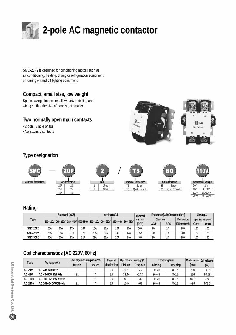
SMC-20P2 is designed for conditioning motors such as air conditioning, heating, drying or refrigeration equipment or turning on and off lighting equipment.
Compact, small size, low weightSpace saving dimensions allow easy installing and wiring so that the size of panels get smaller.
Two normally open main contacts- 2-pole, Single phase- No auxiliary contacts
Rating
Coil characteristics (AC 220V, 60Hz)
Type designation
Standard (AC3) Inching (AC4) Thermal Endurance (××10,000 operations) Closing & Type
100~110V 200~220V 380~440V 500~550V 100~110V 200~220V 380~440V 500~550Vcurrent Electrical Mechanical opening ampere(AC1) AC3 AC4 1200operations/h Close Open
SMC-20P2 20A 20A 17A 14A 18A 18A 13A 10A 30A 20 1.5 200 120 20SMC-25P2 25A 25A 21A 17A 20A 20A 14A 12A 35A 20 1.5 200 150 25SMC-30P2 30A 30A 23A 21A 22A 22A 20A 14A 40A 20 1.5 200 180 30
AC 24V AC 24V 50/60Hz 31 7 2.7 19.2~ ~7.2 30~45 8~15 330 10.28AC 48V AC 48~50V 50/60Hz 31 7 2.7 38.4~ ~14.4 30~45 8~15 156 50.68AC 110V AC 100~120V 50/60Hz 31 7 2.7 80~ ~30 30~45 8~15 85.8 264AC 220V AC 208~240V 50/60Hz 31 7 2.7 176~ ~66 30~45 8~15 ~39 975.0
/SSMMCC
Magnetic contactors
2200PP
Ampere frame20P 2025P 2530P 30
TTSS
Terminal connectionTS ScrewTQ Quick connect
Pole 1 1Pole 2 2Pole
Coil connectionBS ScrewBQ Quick connect
Operational voltage24V 24V48V 48~50V110V 100~120V220V 208~240V
22 BBQQ 111100VV
Type Voltage(AC)Average consumption (VA) Thermal
dissipationOperational voltage(V)
Pick-up Drop-out Closing OpeningCoil current
(mA)Operating time Coil resistance
(ΪΪ)Inrush sealed
M E T A - M E C S E R I E S
31
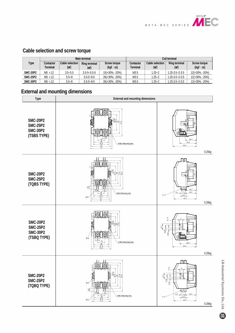
Cable selection and screw torque
SMC-20P2SMC-25P2SMC-30P2(TSBS TYPE)
SMC-20P2SMC-25P2SMC-30P2(TSBQ TYPE)
SMC-20P2SMC-25P2(TQBQ TYPE)
SMC-20P2SMC-25P2(TQBS TYPE)
SMC-20P2 M5 ×12 3.5~5.5 3.5-5~5.5-5 15(+30%, -20%)SMC-25P2 M5 ×12 5.5~8 5.5-5~8-5 26(+30%, -20%)SMC-30P2 M5 ×12 5.5~8 5.5-5~8-5 26(+30%, -20%)
M3.5 1.25~2 1.25-3.5~2-3.5 12(+30%, -20%)M3.5 1.25~2 1.25-3.5~2-3.5 12(+30%, -20%)M3.5 1.25~2 1.25-3.5~2-3.5 12(+30%, -20%)
Type Contactor Terminal
Main terminal Coil terminalContactor Terminal
Cable selection((㎟㎟))
Ring terminal((㎟㎟))
Screw torque(kgf∙∙㎝㎝)
Cable selection((㎟㎟))
Ring terminal((㎟㎟))
Screw torque(kgf∙∙㎝㎝)
Type External and mounting dimensions
External and mounting dimensions
0.25kg
0.26kg
0.25kg
0.26kg
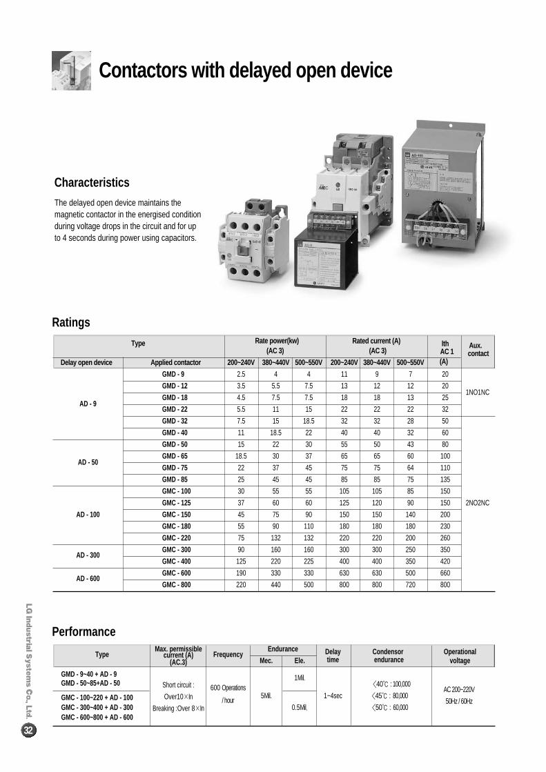
Contactors with delayed open device
32
Type Rate power(kw) Rated current (A) lth Aux.(AC 3) (AC 3) AC 1 contact
Delay open device Applied contactor 200~240V 380~440V 500~550V 200~240V 380~440V 500~550V (A)
GMD - 9 2.5 4 4 11 9 7 20
GMD - 12 3.5 5.5 7.5 13 12 12 201NO1NC
GMD - 18 4.5 7.5 7.5 18 18 13 25AD - 9
GMD - 22 5.5 11 15 22 22 22 32
GMD - 32 7.5 15 18.5 32 32 28 50
GMD - 40 11 18.5 22 40 40 32 60
GMD - 50 15 22 30 55 50 43 80
GMD - 65 18.5 30 37 65 65 60 100AD - 50
GMD - 75 22 37 45 75 75 64 110
GMD - 85 25 45 45 85 85 75 135
GMC - 100 30 55 55 105 105 85 150
GMC - 125 37 60 60 125 120 90 150 2NO2NC
AD - 100 GMC - 150 45 75 90 150 150 140 200
GMC - 180 55 90 110 180 180 180 230
GMC - 220 75 132 132 220 220 200 260
AD - 300GMC - 300 90 160 160 300 300 250 350
GMC - 400 125 220 225 400 400 350 420
AD - 600GMC - 600 190 330 330 630 630 500 660
GMC - 800 220 440 500 800 800 720 800
TypeMax. permissible
FrequencyEndurance Delay Condensor Operationalcurrent (A)
Mec. Ele. time endurance voltage
GMD - 9~40 + AD - 9
(AC.3)
1Mil.GMD - 50~85+AD - 50 Short circuit : 600 Operations 〈40℃ : 100,000
AC 200~220VGMC - 100~220 + AD - 100 Over10×In / hour
5Mil. 1~4sec 〈45℃ : 80,00050Hz / 60Hz
GMC - 300~400 + AD - 300 Breaking :Over 8×In 0.5Mil. 〈50℃ : 60,000GMC - 600~800 + AD - 600
The delayed open device maintains themagnetic contactor in the energised conditionduring voltage drops in the circuit and for upto 4 seconds during power using capacitors.
Characteristics
Ratings
Performance
④④ Easy operation
�
Operationpart
Maincircuit
Manual reset
Auto reset
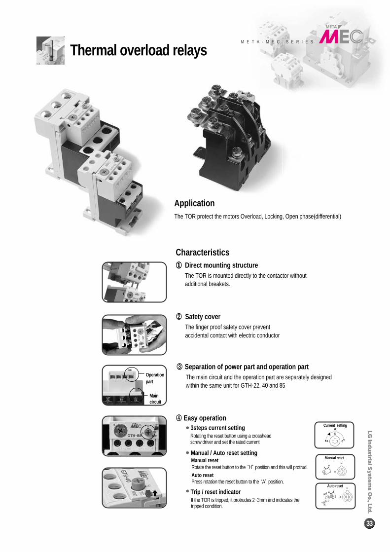
The TOR protect the motors Overload, Locking, Open phase(differential)
Application
�� Direct mounting structureThe TOR is mounted directly to the contactor without additional breakets.
Characteristics
②② Safety coverThe finger proof safety cover prevent accidental contact with electric conductor
③③ Separation of power part and operation partThe main circuit and the operation part are separately designed within the same unit for GTH-22, 40 and 85
Current setting●●3steps current setting
Rotating the reset button using a crossheadscrew driver and set the rated current
●●Manual / Auto reset settingManual resetRotate the reset button to the “H”position and this will protrud. Auto resetPress rotation the reset button to the “A”position.
●●Trip / reset indicatorIf the TOR is tripped, it protrudes 2~3mm and indicates thetripped condition.
Thermal overload relaysM E T A - M E C S E R I E S
33
34
Rated current (A)
Type AC15 DC13
110V 220V 550V 110V 110V
GTH-22, 40, 85 2.5(0.3) 2(0.3) 1(0.3) 0.28(0.28) 0.14(0.14)
GTH-100, 125, 150, 220, 400, 600 2.5(0.3) 2(0.3) 1(0.3) 0.28(0.28) 0.14(0.14)
Contactors Thermal Overload Relays
GMC - 9
GMC - 12GTH(K) - 22
GMC - 18
GMC - 22
GMC - 32GTH(K) - 40
GMC - 40
GMC - 50
GMC - 65GTH(K) - 85
GMC - 75
GMC - 85
GMC - 100GTH(K) - 100
GMC - 125
GMC - 150 GTH(K) - 150GMC - 180
GTH(K) - 220GMC - 220
GMC - 300GTH(K) - 400
GMC - 400
GMC - 600GTH(K) - 600
GMC - 800
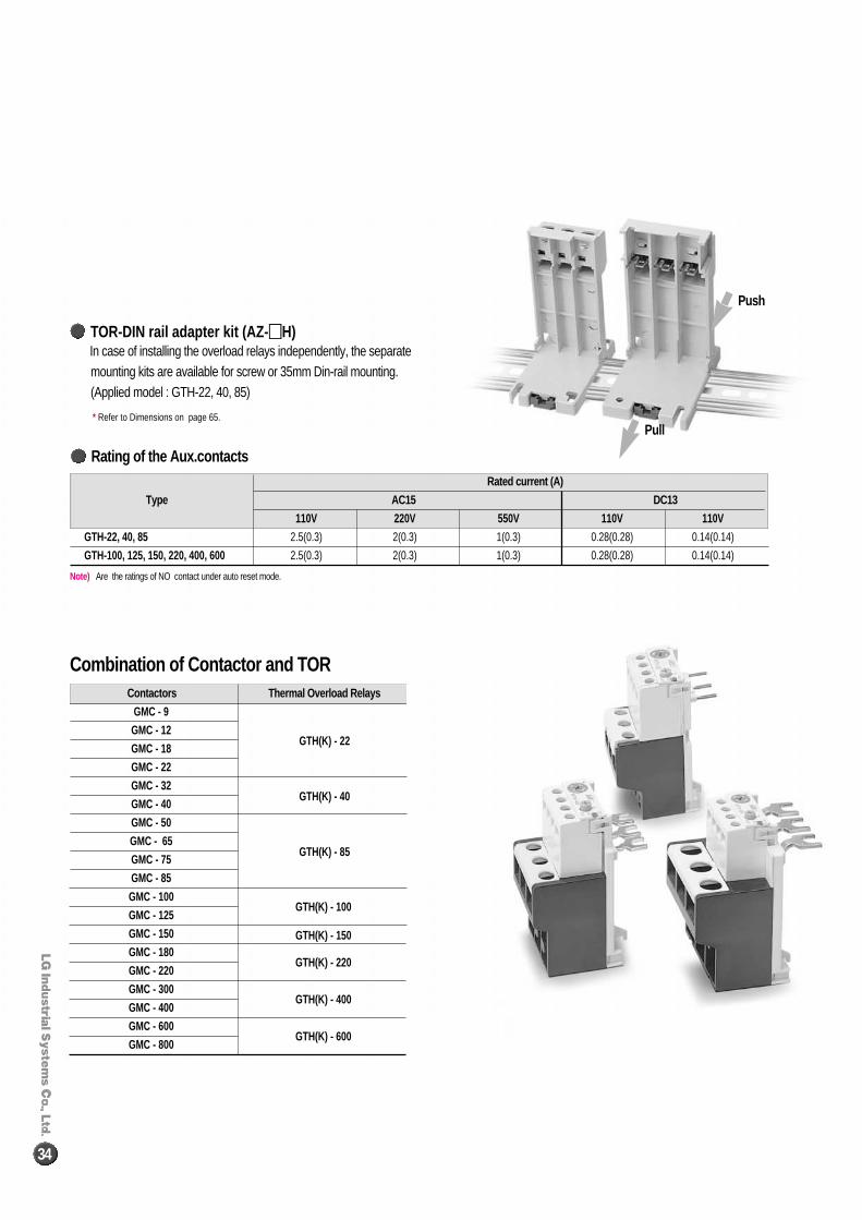
In case of installing the overload relays independently, the separate mounting kits are available for screw or 35mm Din-rail mounting.(Applied model : GTH-22, 40, 85)
TOR-DIN rail adapter kit (AZ- ��H)
* Refer to Dimensions on page 65.
Rating of the Aux.contacts
Note) Are the ratings of NO contact under auto reset mode.
Combination of Contactor and TOR
Pull
Push
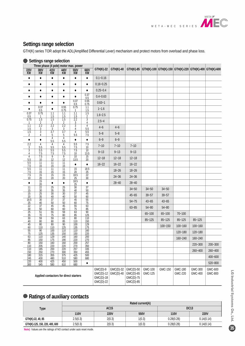
Settings range selectionGTH(K) series TOR adopt the ADL(Amplified Differential Lever) mechanism and protect motors from overload and phase loss.
M E T A - M E C S E R I E S
35
Settings range selection
Ratings of auxiliary contacts
Note) Values are the ratings of NO contact under auto reset mode.
Applied contactors for direct starters
GMC(D)-9 GMC(D)-32 GMC(D)-50 GMC-100 GMC-150 GMC-180 GMC-300 GMC-600GMC(D)-12 GMC(D)-40 GMC(D)-65 GMC-125 GMC-220 GMC-400 GMC-800GMC(D)-18 GMC(D)-75GMC(D)-22 GMC(D)-85
● ● ● ● ● ●
● ● ● ● ● ●
● ● ● ● ● ●
● ● ● ● ●0.370.5
● ● ● ●0.37 0.550.5 0.75
●0.37
●0.55 0.75 1.1
0.5 0.75 1 1.50.37 0.75 1.1 1.1 1.1 1.50.5 1 1.5 1.5 1.5 20.75 1.5 1.5 1.5 2.2 3
1 2 2 2 3 41.1 2.2 2.2 2.2 3 41.5 3 3 3 4 5.51.5 3 3.7 3.7 4 5.52 4 5 5 5.5 7.5
● ●4 4
● ●5.5 5.52.2 4 4 4 5.5 7.53 5.5 5.5 5.5 7.5 103 5.5 5.5 5.5 7.5 104 7.5 7.5 7.5 10 13.54 7.5 9 9 10 15
5.5 10 12 12 13.5 205.5 11 11 11
● ●7.5 15 15 155.5 11 11 11 15 18.57.5 15 15 15 20 257.5 15 15 15 18.5 2210 20 20 20 25 30
●15
● ●18.5
●20 2511 22 25 25 30 3715 30 35 35 40 5015 25 30 30 37 4520 35 40 40 50 60
18.5 30 37 37 45 5525 40 50 50 60 7522 37 45 45 55 6330 50 60 60 75 8525 51 55 59 63 9035 70 75 80 85 12530 59 59 63 80 11040 80 80 85 110 15045 80 80 90 100 12960 110 110 125 135 17555 90 100 110 110 16075 125 135 150 150 22063 110 129 140 160 20085 150 175 190 220 27080 150 160 160 200 257110 205 220 220 270 350110 185 200 220 257 335150 250 270 300 350 455180 315 355 375 425 500245 430 480 510 580 680220 400 425 450 500
●300 545 580 610 680
0.1~0.16
0.16~0.25
0.25~0.4
0.4~0.63
0.63~1
1~1.6
1.6~2.5
2.5~4
4~6
5~8
6~9
7~10
9~13
12~18
16~22
4~6
5~8
6~9
7~10
9~13
12~18
16~22
18~26
24~36
28~40
7~10
9~13
12~18
16~22
18~26
24~36
28~40
34~50
45~65
54~75
63~85
34~50
39~57
43~65
54~80
65~100
85~125
34~50
39~57
43~65
54~80
65~100
85~125
100~150
70~100
85~125
100~160
120~180
160~240
85~125
100~160
120~180
160~240
220~300
260~400
200~300
260~400
400~600
520~800
Three phase (4 pole) motor max. powerGTH(K)-22 GTH(K)-40 GTH(K)-85 GTH(K)-100 GTH(K)-150 GTH(K)-220 GTH(K)-400 GTH(K)-600220V
KW380VKW
415V KW
440V KW
550V KW
660V KW
Rated current(A)AC15
110V 220V 550V 110V 220V
DC13Type
GTH(K)-22, 40, 85
GTH(K)-125, 150, 220, 400, 600
2.5(0.3) 2(0.3) 1(0.3) 0.28(0.28) 0.14(0.14)
2.5(0.3) 2(0.3) 1(0.3) 0.28(0.28) 0.14(0.14)
36
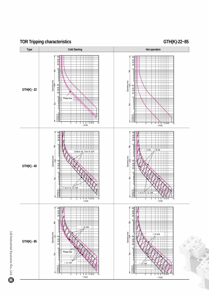
Type Cold Starting Hot operation
GTH(K) - 22
GTH(K) - 40
GTH(K) - 85
TOR Tripping characteristics GTH(K)-22~85
M E T A - M E C S E R I E S
37
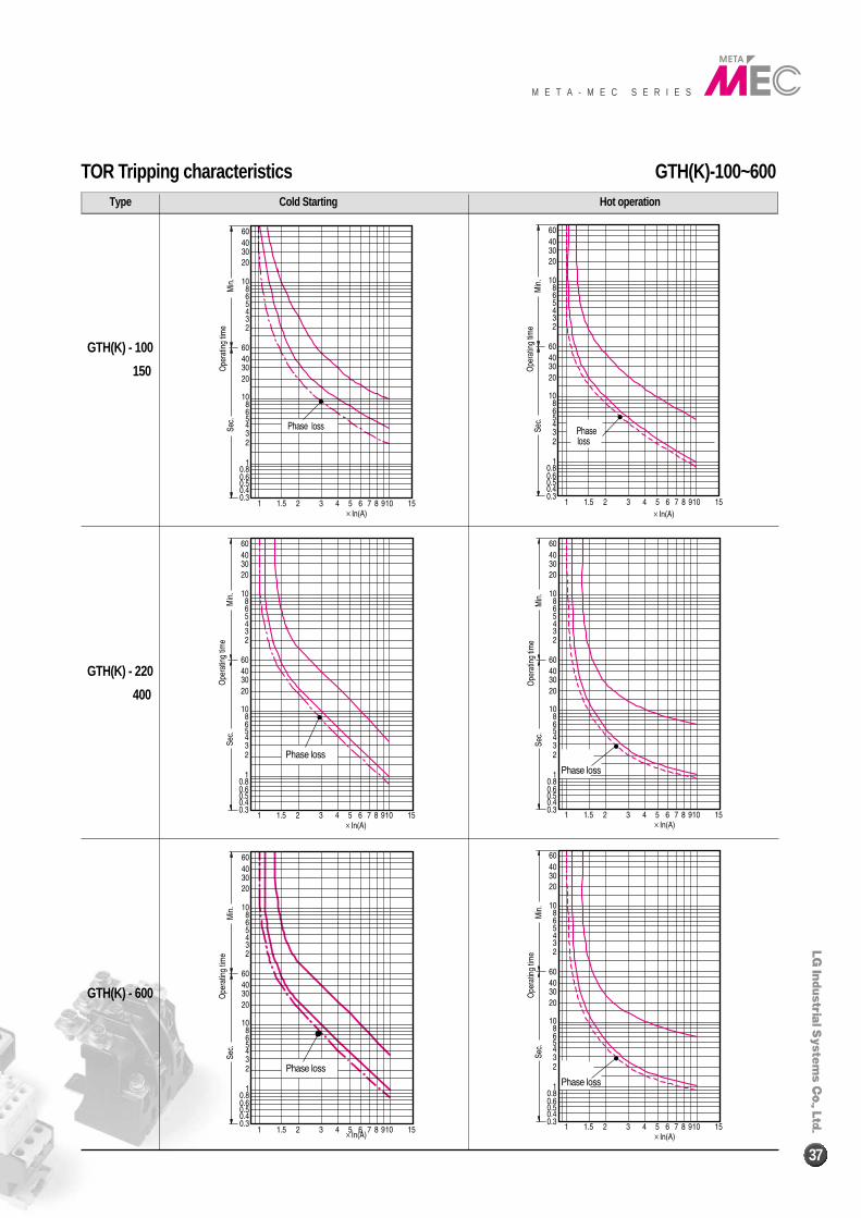
GTH(K) - 100
150
GTH(K) - 220
400
GTH(K) - 600
TOR Tripping characteristics GTH(K)-100~600Type Cold Starting Hot operation
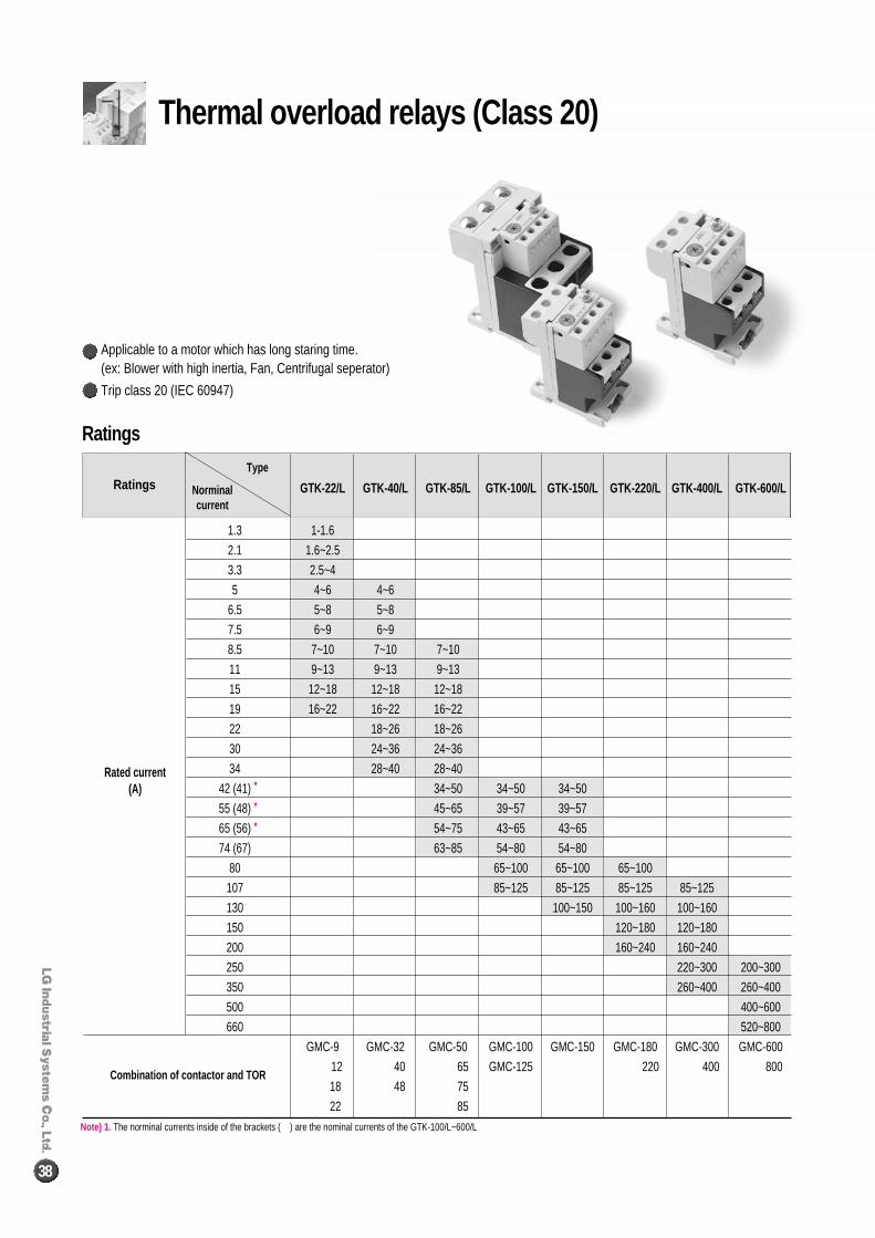
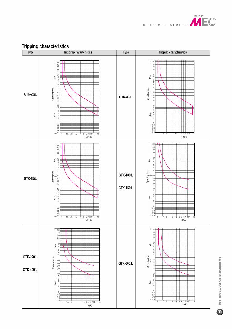
GTK-22/L GTK-40/L GTK-85/L GTK-100/L GTK-150/L GTK-220/L GTK-400/L GTK-600/L
1.3 1-1.6
2.1 1.6~2.5
3.3 2.5~4
5 4~6 4~6
6.5 5~8 5~8
7.5 6~9 6~9
8.5 7~10 7~10 7~10
11 9~13 9~13 9~13
15 12~18 12~18 12~18
19 16~22 16~22 16~22
22 18~26 18~26
30 24~36 24~36
34 28~40 28~40
42 (41) 34~50 34~50 34~50
55 (48) 45~65 39~57 39~57
65 (56) 54~75 43~65 43~65
74 (67) 63~85 54~80 54~80
80 65~100 65~100 65~100
107 85~125 85~125 85~125 85~125
130 100~150 100~160 100~160
150 120~180 120~180
200 160~240 160~240
250 220~300 200~300
350 260~400 260~400
500 400~600
660 520~800
GMC-9 GMC-32 GMC-50 GMC-100 GMC-150 GMC-180 GMC-300 GMC-600
12 40 65 GMC-125 220 400 800
18 48 75
22 85
Ratings
Ratings
Combination of contactor and TOR
Type
Norminal current
Rated current(A)
Note) 1. The norminal currents inside of the brackets ( ) are the nominal currents of the GTK-100/L~600/L
*
*
*
Thermal overload relays (Class 20)
Applicable to a motor which has long staring time. (ex: Blower with high inertia, Fan, Centrifugal seperator)
Trip class 20 (IEC 60947)
38
GTK-22/LGTK-40/L
GTK-85/LGTK-100/L
GTK-150/L
GTK-220/L
GTK-400/L
GTK-600/L
Type TypeTripping characteristics Tripping characteristics
Tripping characteristics
M E T A - M E C S E R I E S
39
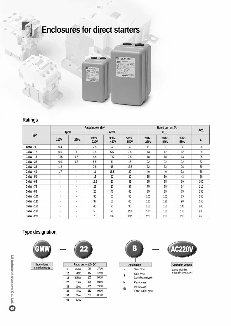
Rated power (kw) Rated current (A)
Type 1pole AC 3 AC 3 AC1
110V 220V 200V~ 380V~ 500V~ 200V~ 380V~ 500V~220V 440V 550V 220V 440V 550V A
GMW - 9 0.4 0.8 2.5 4 4 11 9 7 20
GMW - 12 0.5 1 3.5 5.5 7.5 13 12 12 20
GMW - 18 0.75 1.5 4.5 7.5 7.5 18 18 13 25
GMW - 22 0.9 1.8 5.5 11 15 22 22 22 32
GMW - 32 1.2 - 7.5 15 18.5 32 32 28 50
GMW - 40 1.7 - 11 18.5 22 40 40 32 60
GMW - 50 - - 15 22 30 55 50 43 80
GMW - 65 - - 18.5 30 33 65 65 60 100
GMW - 75 - - 22 37 37 75 75 64 110
GMW - 85 - - 25 45 45 85 85 75 135
GMW - 100 - - 30 55 55 105 105 85 150
GMW - 125 - - 37 60 60 125 120 90 150
GMW - 150 - - 45 75 90 150 150 140 200
GMW - 180 - - 55 90 110 180 180 180 230
GMW - 220 - - 75 132 132 220 220 200 260
Ratings
Type designation
Enclosed type magnetic switches
GMW
Operation voltage
AC220V
9 2.7kW
12 4kW
18 5.5kW
22 7.5kW
32 11kW
40 15kW
50 22kW
65 30kW
75 37kW
85 37kW
100 50kW
125 60kW
150 75kW
180 90kW
220 110kW
Rated current ((444400VV)) Application- Steel case
BB Steel case(push button type)
MM Plastic case
MMBB Plastic case(Push button type)
Same with the magnetic contactors
B22
Enclosures for direct starters
40
M E T A - M E C S E R I E S
41
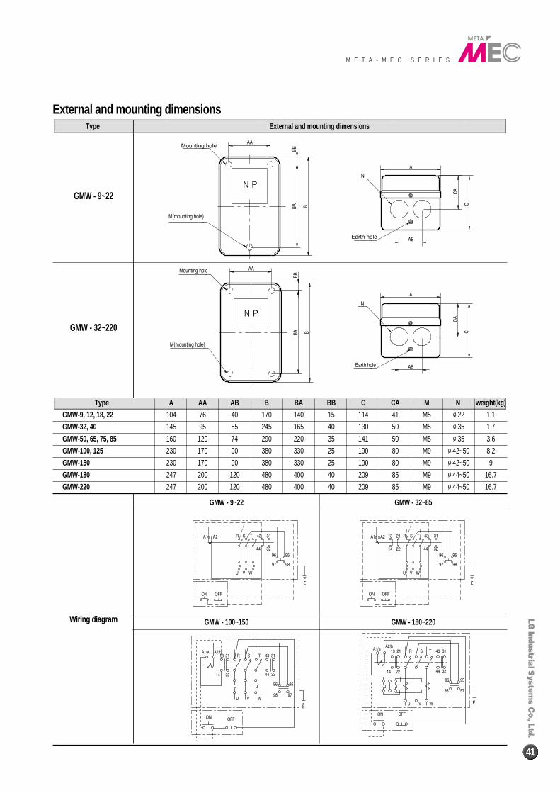
Type External and mounting dimensions
GMW - 9~22
GMW - 32~220
Wiring diagram
External and mounting dimensions
Type A AA AB B BA BB C CA M N weight (kg)
GMW-9, 12, 18, 22 104 76 40 170 140 15 114 41 M5 ∅22 1.1
GMW-32, 40 145 95 55 245 165 40 130 50 M5 ∅35 1.7
GMW-50, 65, 75, 85 160 120 74 290 220 35 141 50 M5 ∅35 3.6
GMW-100, 125 230 170 90 380 330 25 190 80 M9 ∅42~50 8.2
GMW-150 230 170 90 380 330 25 190 80 M9 ∅42~50 9
GMW-180 247 200 120 480 400 40 209 85 M9 ∅44~50 16.7
GMW-220 247 200 120 480 400 40 209 85 M9 ∅44~50 16.7
GMW - 9~22
GMW - 100~150 GMW - 180~220
GMW - 32~85
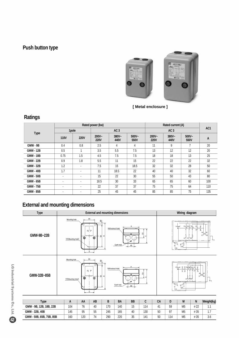
Rated power (kw) Rated current (A)
Type 1pole AC 3 AC 3
AC1
110V 220V 200V~ 380V~ 500V~ 200V~ 380V~ 500V~220V 440V 550V 220V 440V 550V A
GMW - 9B 0.4 0.8 2.5 4 4 11 9 7 20
GMW - 12B 0.5 1 3.5 5.5 7.5 13 12 12 20
GMW - 18B 0.75 1.5 4.5 7.5 7.5 18 18 13 25
GMW - 22B 0.9 1.8 5.5 11 15 22 22 22 32
GMW - 32B 1.2 - 7.5 15 18.5 32 32 28 50
GMW - 40B 1.7 - 11 18.5 22 40 40 32 60
GMW - 50B - - 15 22 30 55 50 43 80
GMW - 65B - - 18.5 30 33 65 65 60 100
GMW - 75B - - 22 37 37 75 75 64 110
GMW - 85B - - 25 45 45 85 85 75 135
Type External and mounting dimensions Wiring diagram
GMW-9B~22B
GMW-32B~85B
Ratings
External and mounting dimensions
Type A AA AB B BA BB C CA D M N Weight( kg)
GMW - 9B, 12B, 18B, 22B 104 76 40 170 140 15 114 41 59 M5 ∅22 1.1
GMW - 32B, 40B 145 95 55 245 165 40 130 50 97 M5 ∅35 1.7
GMW - 50B, 65B, 75B, 85B 160 120 74 290 220 35 141 50 114 M5 ∅35 3.6
[ Metal enclosure ]
Push button type
42
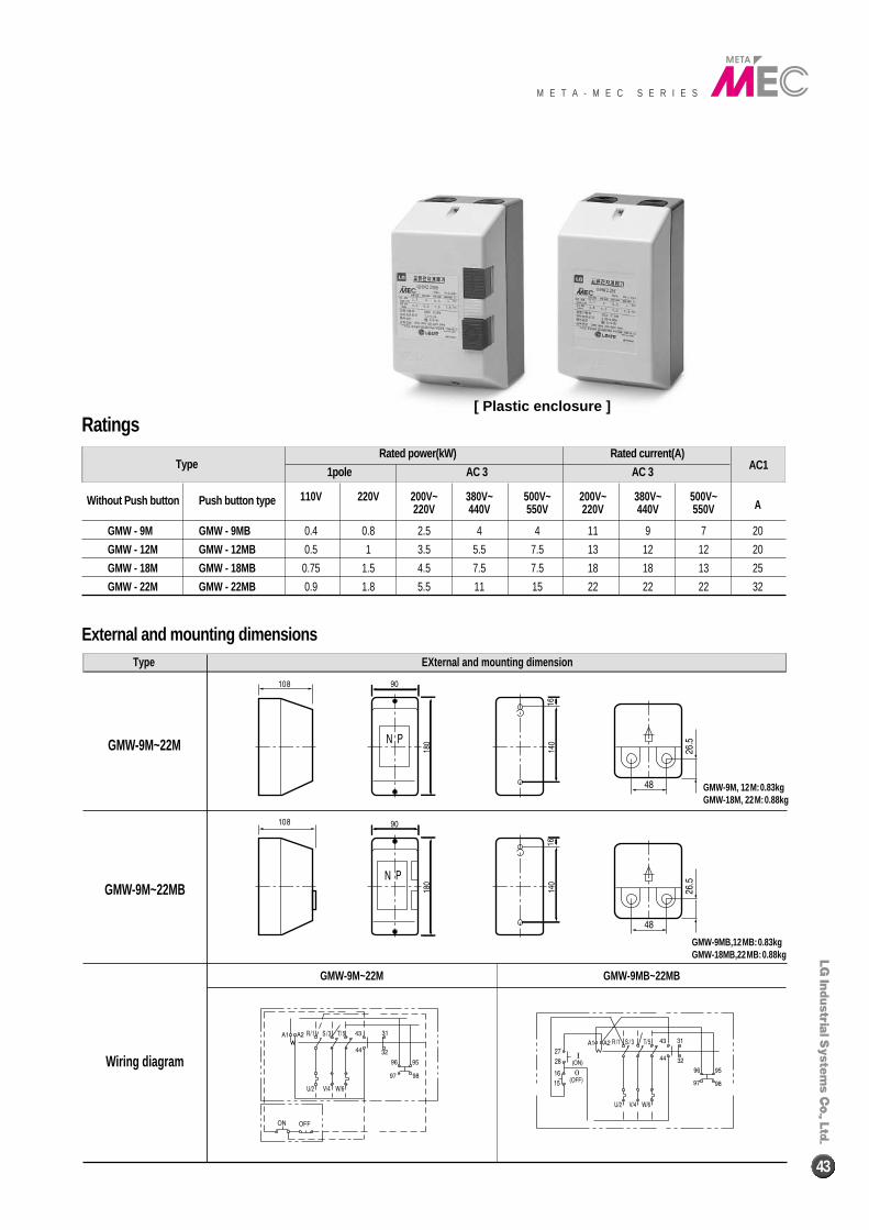
Type Rated power(kW) Rated current(A)
AC1 1pole AC 3 AC 3
110V 220V 200V~ 380V~ 500V~ 200V~ 380V~ 500V~Without Push button Push button type220V 440V 550V 220V 440V 550V A
GMW - 9M GMW - 9MB 0.4 0.8 2.5 4 4 11 9 7 20
GMW - 12M GMW - 12MB 0.5 1 3.5 5.5 7.5 13 12 12 20
GMW - 18M GMW - 18MB 0.75 1.5 4.5 7.5 7.5 18 18 13 25
GMW - 22M GMW - 22MB 0.9 1.8 5.5 11 15 22 22 22 32
Type EXternal and mounting dimension
GMW-9M~22M
GMW-9M~22MB
Wiring diagram
GMW-9M~22M GMW-9MB~22MB
External and mounting dimensions
Ratings
GMW-9M, 12M:0.83kgGMW-18M, 22M:0.88kg
GMW-9MB,12MB:0.83kgGMW-18MB,22MB:0.88kg
[ Plastic enclosure ]
M E T A - M E C S E R I E S
43
Dimensions and wiring diagrams
44
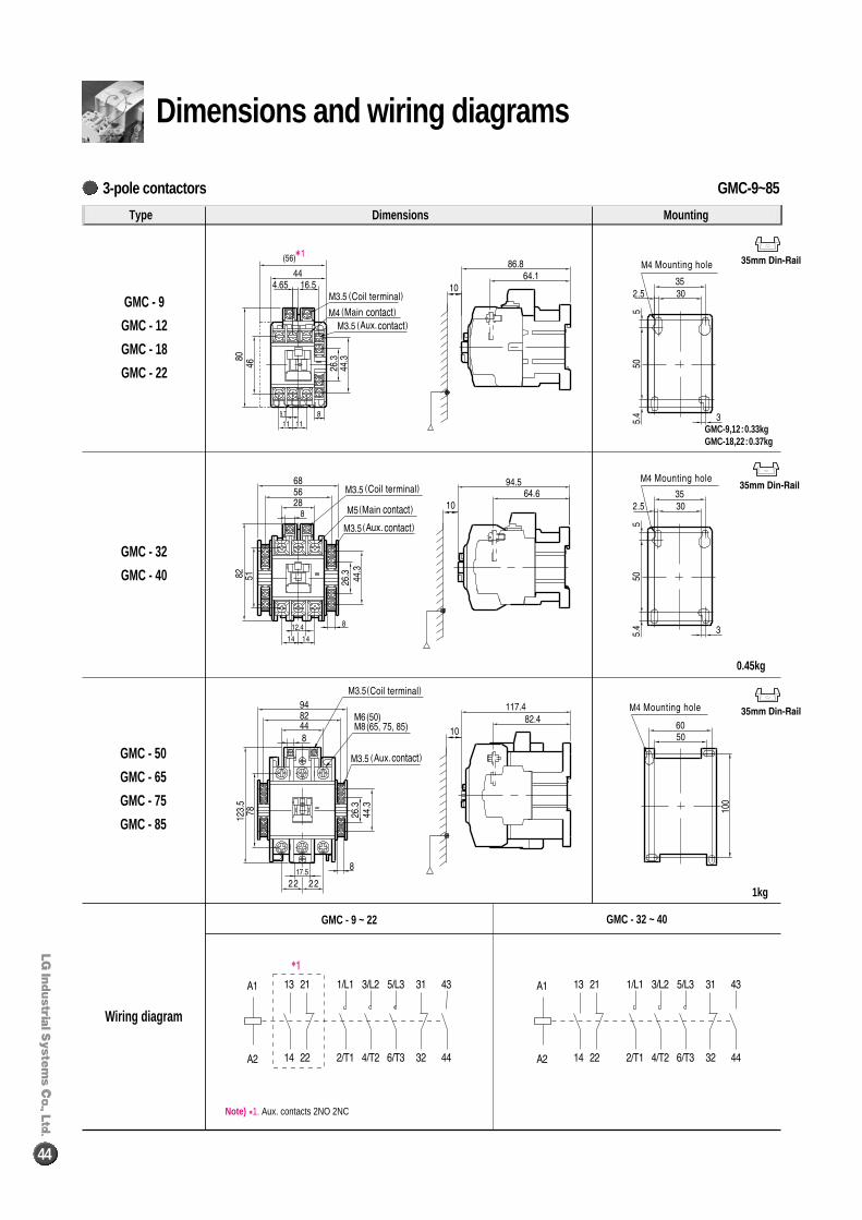
Type Dimensions Mounting
GMC - 9
GMC - 12
GMC - 18
GMC - 22
GMC - 32
GMC - 40
GMC - 50
GMC - 65
GMC - 75
GMC - 85
Wiring diagram
GMC-9,12:0.33kgGMC-18,22:0.37kg
0.45kg
1kg
Note) �1. Aux. contacts 2NO 2NC
GMC - 9 ~ 22 GMC - 32 ~ 40
GMC-9~853-pole contactors
M E T A - M E C S E R I E S
45
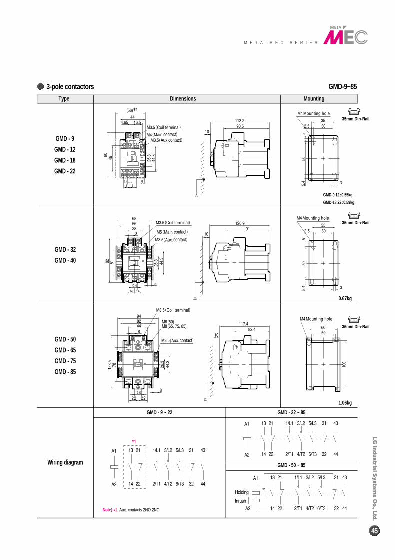
GMD-9~85
GMD-9,12:0.55kg
GMD-18,22:0.59kg
0.67kg
1.06kg
Type Dimensions Mounting
GMD - 9
GMD - 12
GMD - 18
GMD - 22
GMD - 32
GMD - 40
GMD - 50
GMD - 65
GMD - 75
GMD - 85
Wiring diagram
Note) �1. Aux. contacts 2NO 2NC
GMD - 9 ~ 22 GMD - 32 ~ 85
GMD - 50 ~ 85
3-pole contactors
GMC-100~2203-pole contactors
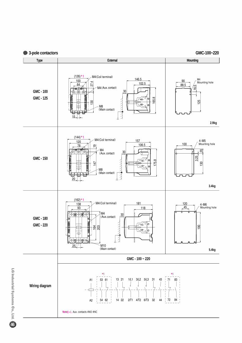
46
Type External Mounting
GMC - 100
GMC - 125
GMC - 150
GMC - 180
GMC - 220
Wiring diagram
GMC - 100 ~ 220
Note) �1. Aux. contacts 4NO 4NC
2.9kg
3.4kg
5.4kg
GMC-300~8003-pole contactors
M E T A - M E C S E R I E S
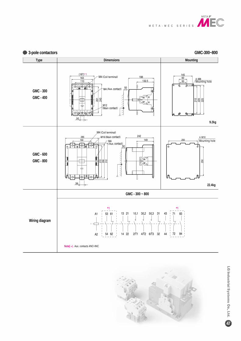
47
Type Dimensions Mounting
GMC - 300
GMC - 400
GMC - 600
GMC - 800
Wiring diagram
GMC - 300 ~ 800
Note) �1. Aux. contacts 4NO 4NC
9.2kg
22.4kg
GMS-9~85Direct starters
48
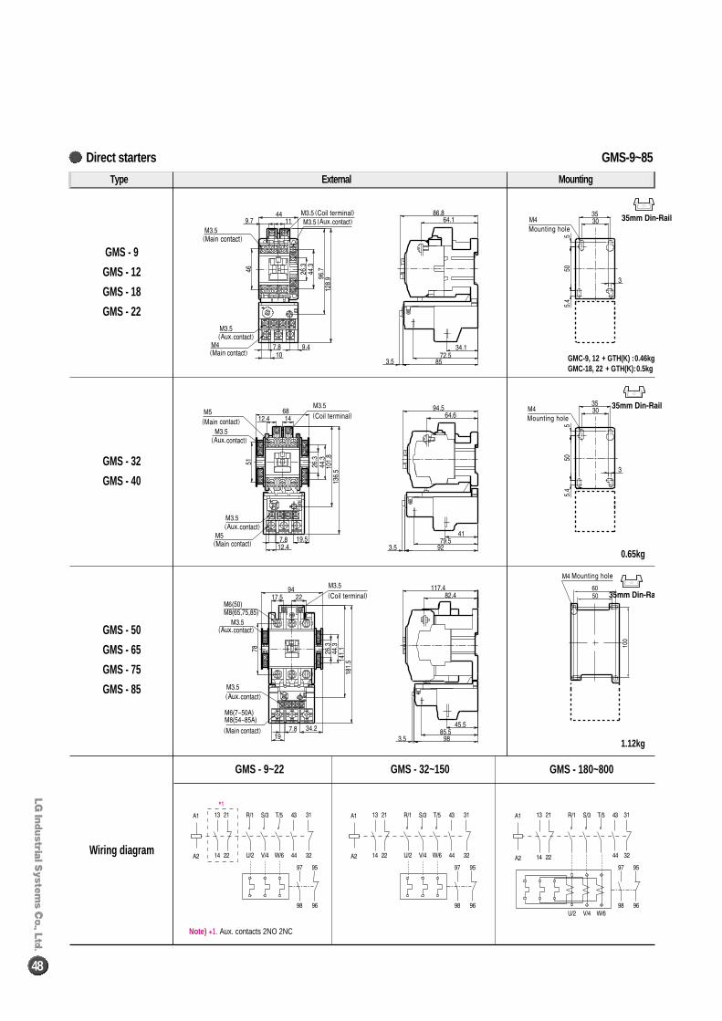
Type External Mounting
GMS - 9
GMS - 12
GMS - 18
GMS - 22
GMS - 32
GMS - 40
GMS - 50
GMS - 65
GMS - 75
GMS - 85
Wiring diagram
GMS - 9~22 GMS - 32~150 GMS - 180~800
0.65kg
1.12kg
GMC-9, 12 + GTH(K) :0.46kgGMC-18, 22 + GTH(K):0.5kg
Note) �1. Aux. contacts 2NO 2NC
GMS-100~800Direct starters
M E T A - M E C S E R I E S
49
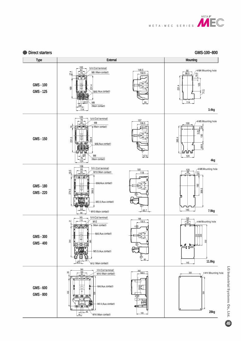
Type External Mounting
GMS - 100
GMS - 125
GMS - 150
GMS - 180
GMS - 220
GMS - 300
GMS - 400
GMS - 600
GMS - 800
28kg
11.8kg
7.9kg
4kg
3.4kg
GMC-9/4~85/44-pole contactors
50
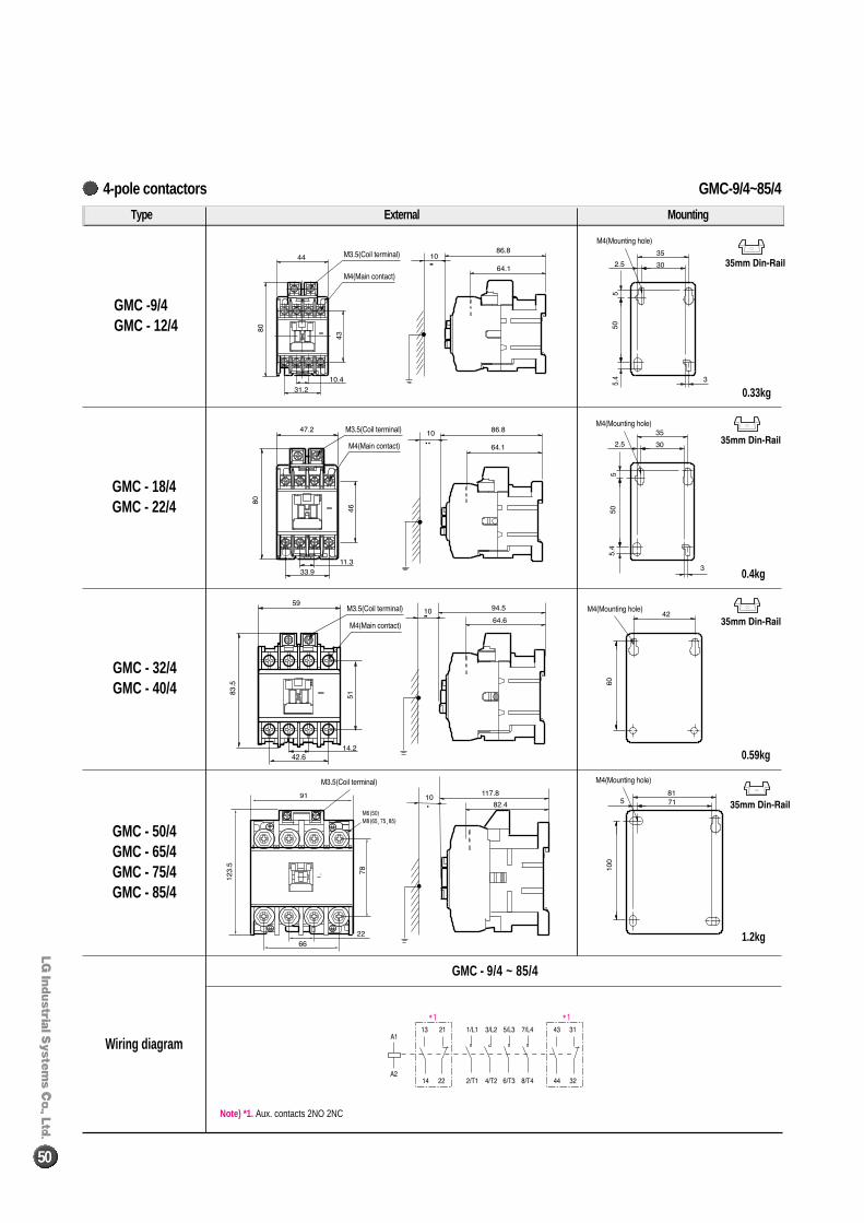
Type External Mounting
GMC -9/4GMC - 12/4
GMC - 18/4GMC - 22/4
GMC - 32/4GMC - 40/4
GMC - 50/4GMC - 65/4GMC - 75/4GMC - 85/4
Wiring diagram
GMC - 9/4 ~ 85/4
1.2kg
0.59kg
0.4kg
0.33kg
Note) *1. Aux. contacts 2NO 2NC
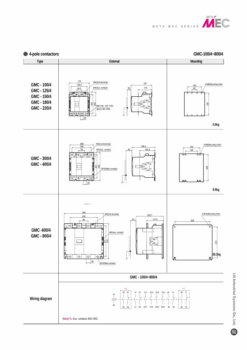
GMC-100/4~800/44-pole contactors
M E T A - M E C S E R I E S
51
Type External Mounting
GMC - 100/4GMC - 125/4GMC - 150/4GMC - 180/4GMC - 220/4
GMC - 300/4GMC - 400/4
GMC -600/4GMC - 800/4
Wiring diagram
GMC - 100/4~800/4
9.9kg
5.6kg
26.3kg
Note) *1. Aux. contacts 4NO 4NC
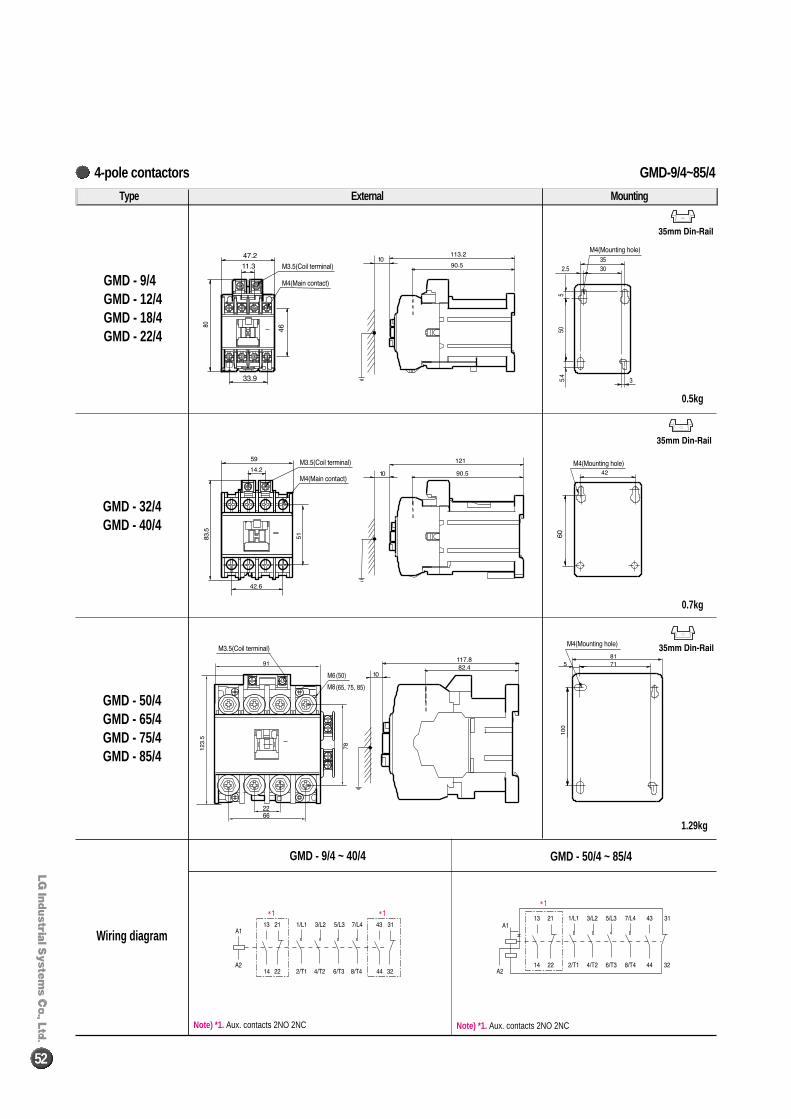
GMD-9/4~85/44-pole contactors
52
Type External Mounting
GMD - 9/4GMD - 12/4GMD - 18/4GMD - 22/4
GMD - 32/4GMD - 40/4
GMD - 50/4GMD - 65/4GMD - 75/4GMD - 85/4
Wiring diagram
GMD - 9/4 ~ 40/4 GMD - 50/4 ~ 85/4
0.7kg
0.5kg
1.29kg
Note) *1. Aux. contacts 2NO 2NC Note) *1. Aux. contacts 2NO 2NC
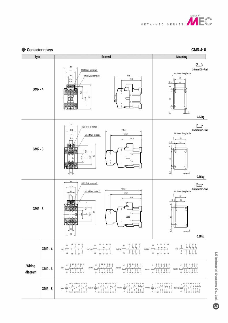
GMR-4~8Contactor relays
M E T A - M E C S E R I E S
53
Type External Mounting
GMR - 4
GMR - 6
GMR - 8
GMR - 8
GMR - 6
GMR - 4
Wiring
diagram
0.33kg
0.36kg
0.38kg
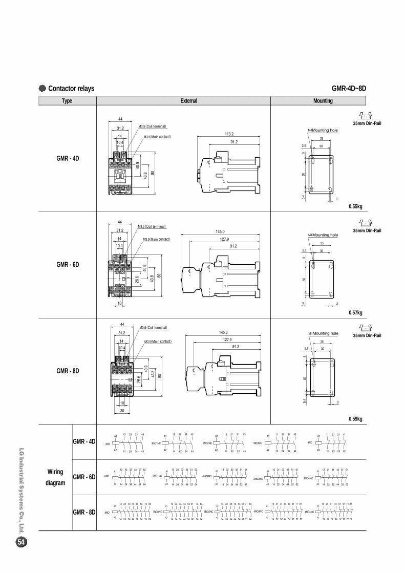
GMR-4D~8DContactor relays
54
Type External Mounting
GMR - 4D
GMR - 6D
GMR - 8D
Wiring
diagram
GMR - 8D
GMR - 6D
GMR - 4D
0.55kg
0.57kg
0.59kg
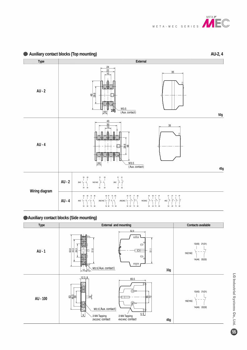
AU-2, 4Auxiliary contact blocks (Top mounting)
M E T A - M E C S E R I E S
55
Auxiliary contact blocks (Side mounting)
External Type
50g28g
33g
45g
45g
AU - 2
AU - 4
Wiring diagram
AU - 2
AU - 4
AU - 1
AU - 100
External and mounting Contacts availableType
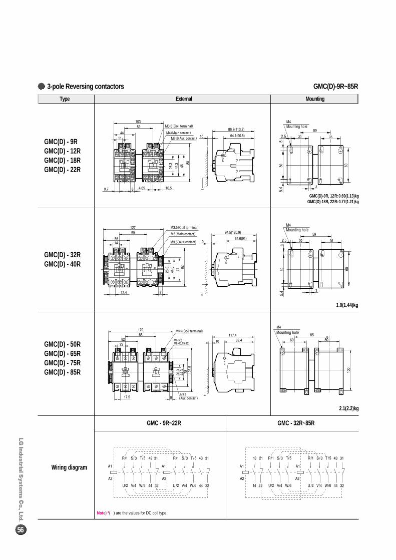
GMC(D)-9R~85R3-pole Reversing contactors
56
Type External Mounting
GMC(D) - 9RGMC(D) - 12RGMC(D) - 18RGMC(D) - 22R
GMC(D) - 32RGMC(D) - 40R
GMC(D) - 50RGMC(D) - 65RGMC(D) - 75RGMC(D) - 85R
Wiring diagram
GMC - 9R~22R GMC - 32R~85R
1.0(1.44)kg
2.1(2.2)kg
GMC(D)-9R, 12R:0.69(1.13)kgGMC(D)-18R, 22R:0.77(1.21)kg
Note) * ( ) are the values for DC coil type.
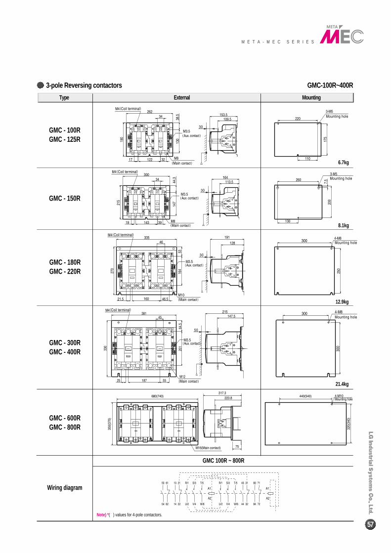
GMC-100R~400R3-pole Reversing contactors
M E T A - M E C S E R I E S
57Note) * ( ) values for 4-pole contactors.
Type External Mounting
GMC - 100RGMC - 125R
GMC - 150R
GMC - 180RGMC - 220R
GMC - 300RGMC - 400R
GMC - 600RGMC - 800R
Wiring diagram
GMC 100R ~ 800R
6.7kg
8.1kg
12.9kg
21.4kg
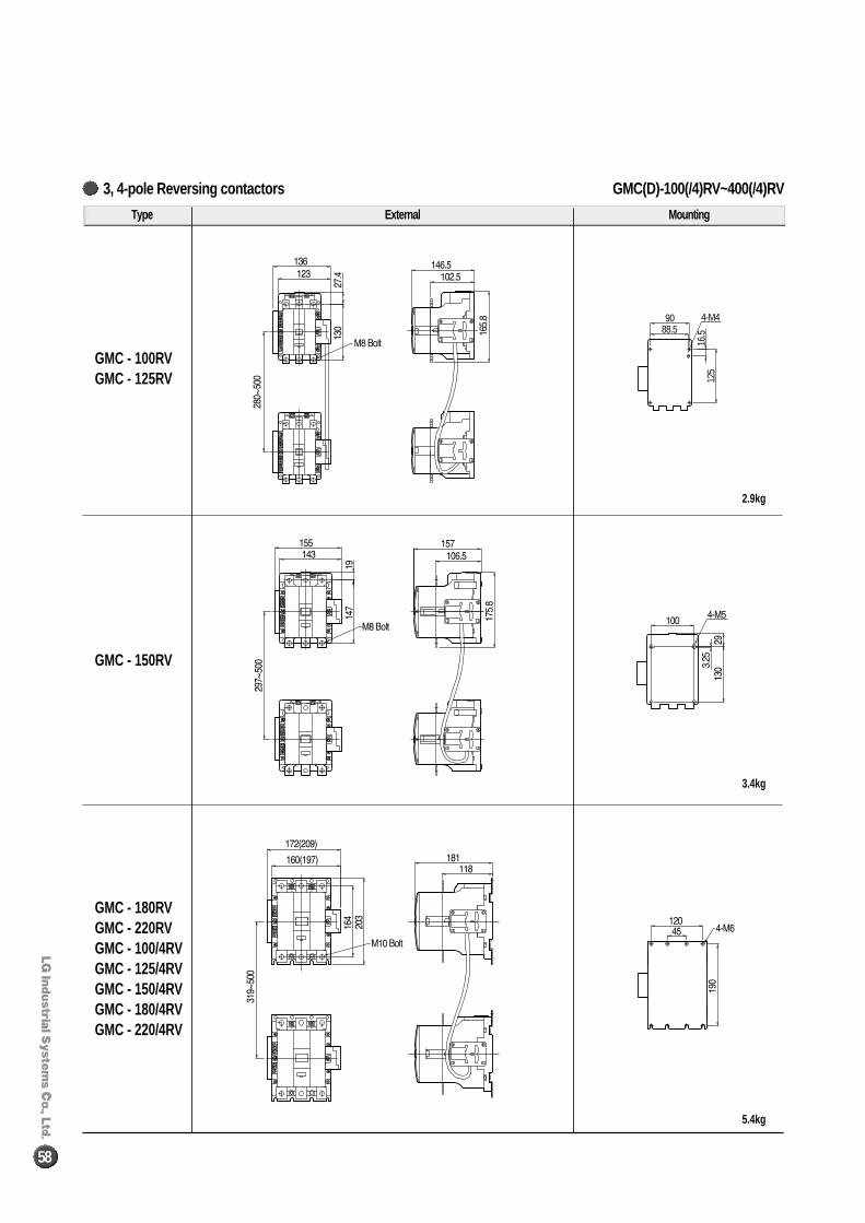
58
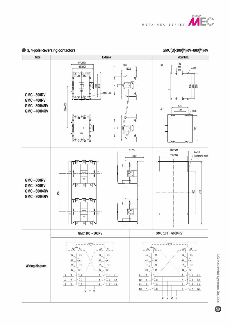
3, 4-pole Reversing contactors
4-M4
16.5
125
9088.5
Type External Mounting
GMC - 100RVGMC - 125RV
GMC - 150RV
GMC - 180RVGMC - 220RVGMC - 100/4RVGMC - 125/4RVGMC - 150/4RVGMC - 180/4RVGMC - 220/4RV
GMC(D)-100(/4)RV~400(/4)RV
2.9kg
3.4kg
5.4kg
M E T A - M E C S E R I E S
59
3, 4-pole Reversing contactors
Type External Mounting
GMC - 300RVGMC - 400RVGMC - 300/4RVGMC - 400/4RV
GMC - 600RVGMC - 800RVGMC - 600/4RVGMC - 800/4RV
GMC(D)-300(/4)RV~800(/4)RV
Wiring diagram
GMC 100 ~ 600RV GMC 100 ~ 600/4RV
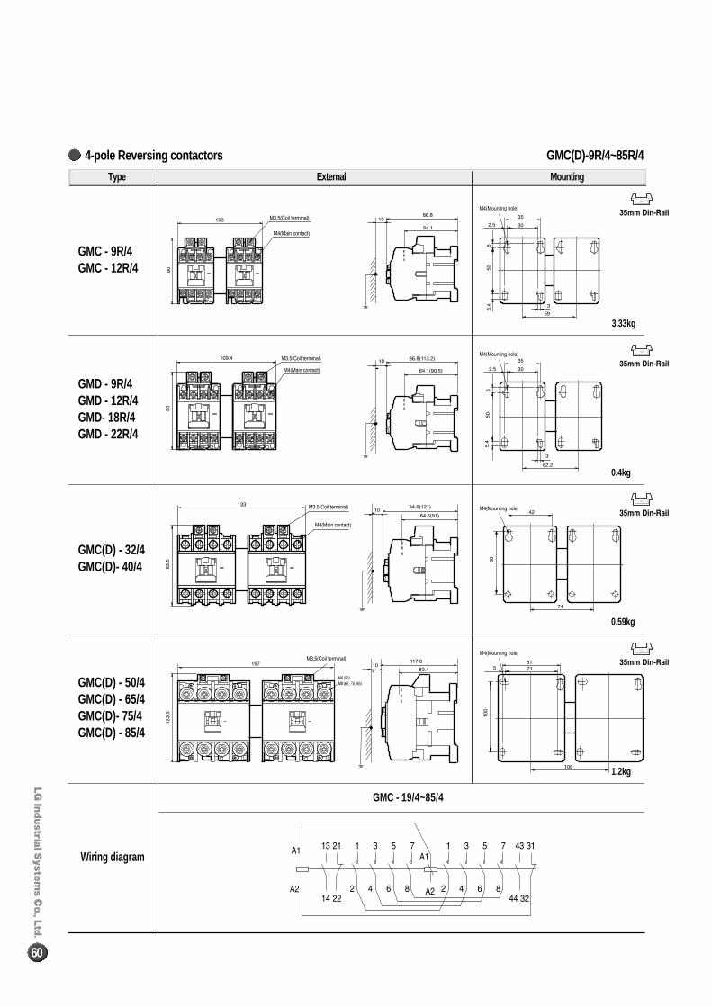
GMC(D)-9R/4~85R/44-pole Reversing contactors
60
Type External Mounting
GMC - 9R/4GMC - 12R/4
GMD - 9R/4GMD - 12R/4GMD- 18R/4GMD - 22R/4
GMC(D) - 32/4GMC(D)- 40/4
GMC(D) - 50/4GMC(D) - 65/4GMC(D)- 75/4GMC(D) - 85/4
Wiring diagram
GMC - 19/4~85/4
1.2kg
0.59kg
0.4kg
3.33kg
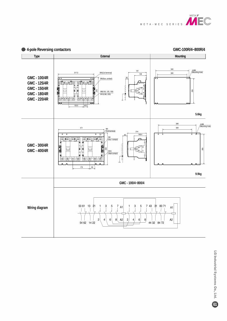
GMC-100R/4~800R/44-pole Reversing contactors
M E T A - M E C S E R I E S
61
Type External Mounting
GMC - 100/4RGMC - 125/4RGMC - 150/4RGMC - 180/4RGMC - 220/4R
GMC - 300/4RGMC - 400/4R
Wiring diagram
GMC - 100/4~800/4
9.9kg
5.6kg
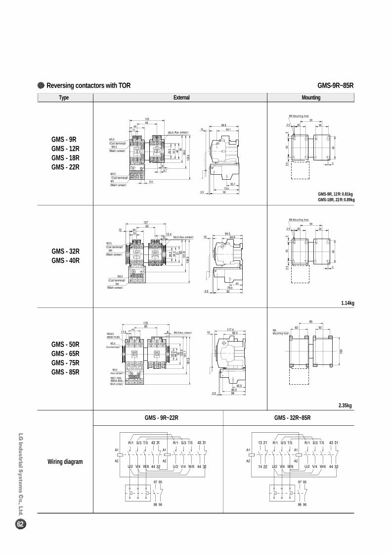
GMS-9R~85RReversing contactors with TOR
62
Type External Mounting
GMS - 9RGMS - 12RGMS - 18RGMS - 22R
GMS - 32RGMS - 40R
GMS - 50RGMS - 65RGMS - 75RGMS - 85R
Wiring diagram
GMS - 9R~22R GMS - 32R~85R
1.14kg
2.35kg
GMS-9R, 12R:0.81kgGMS-18R, 22R:0.89kg
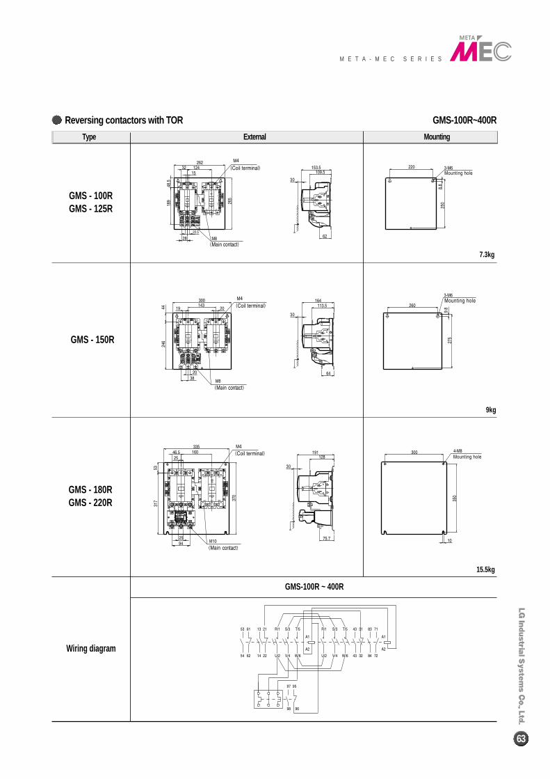
GMS-100R~400RReversing contactors with TOR
M E T A - M E C S E R I E S
63
Type External Mounting
GMS - 100RGMS - 125R
GMS - 150R
GMS - 180RGMS - 220R
Wiring diagram
GMS-100R ~ 400R
7.3kg
9kg
15.5kg
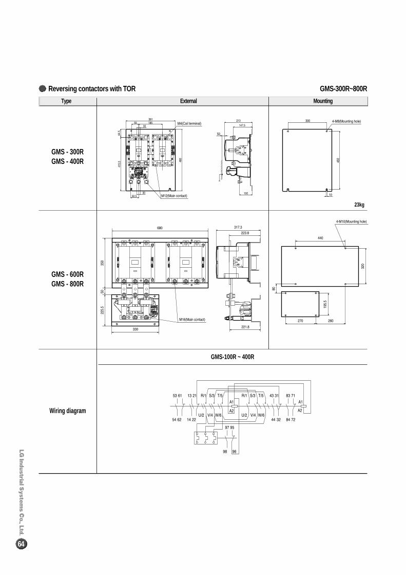
GMS-300R~800RReversing contactors with TOR
64
Type External Mounting
GMS - 300RGMS - 400R
GMS - 600RGMS - 800R
Wiring diagram
GMS-100R ~ 400R
23kg
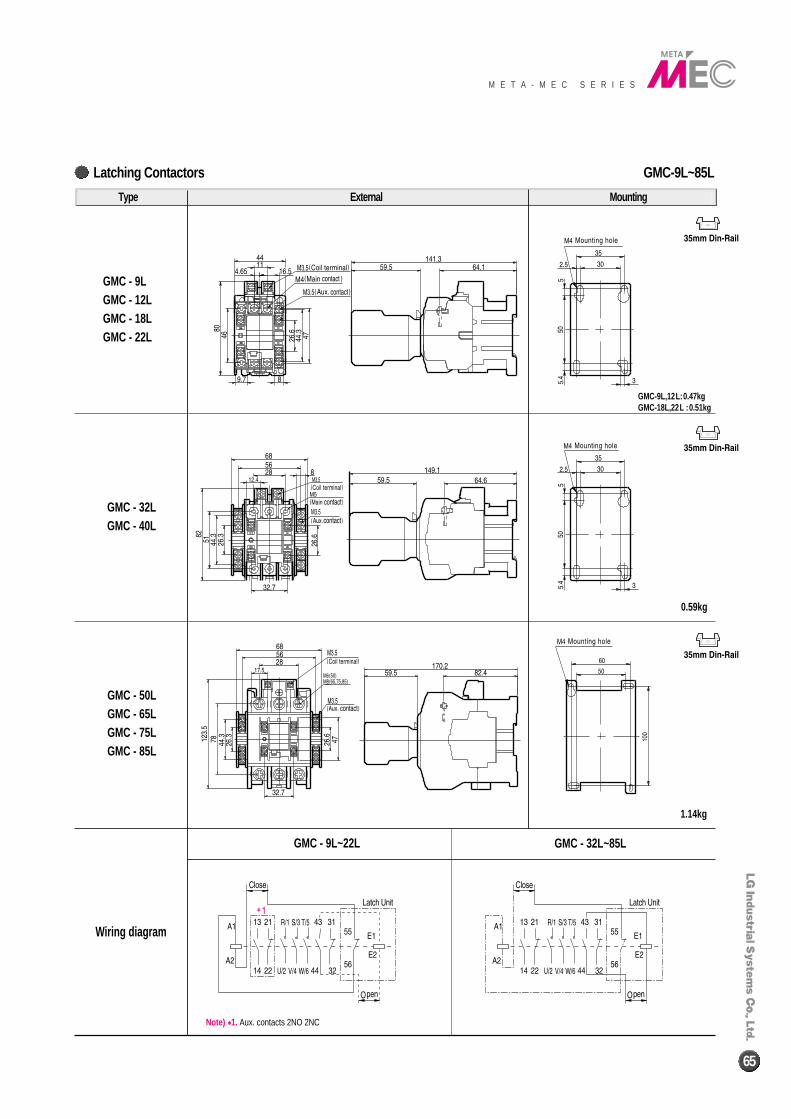
GMC-9L~85LLatching Contactors
M E T A - M E C S E R I E S
65
GMC - 9LGMC - 12LGMC - 18LGMC - 22L
GMC - 32LGMC - 40L
GMC - 50LGMC - 65LGMC - 75LGMC - 85L
GMC - 9L~22L GMC - 32L~85L
0.59kg
1.14kg
GMC-9L,12L:0.47kgGMC-18L,22L :0.51kg
Type External Mounting
Wiring diagram
Note) ��1. Aux. contacts 2NO 2NC
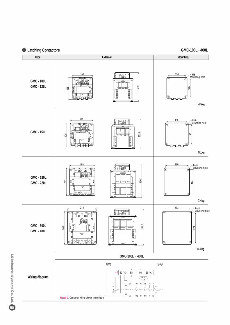
GMC-100L~ 400LLatching Contactors
66
GMC - 100LGMC - 125L
GMC - 150L
GMC - 180LGMC - 220L
GMC - 300LGMC - 400L
GMC-100L ~ 400L
11.6kg
7.4kg
5.1kg
4.5kg
Type External Mounting
Wiring diagram
Note) *1. Customer wiring shown intermittent
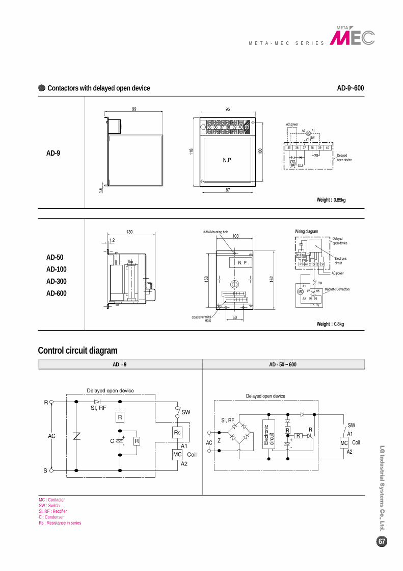
AD-9~600Contactors with delayed open device
M E T A - M E C S E R I E S
67
AD - 9
AD-50
AD-100
AD-300
AD-600
AD-9
AD - 50 ~ 600
Control circuit diagram
MC : ContactorSW : SwitchSl, RF : RectifierC : CondenserRs : Resistance in series
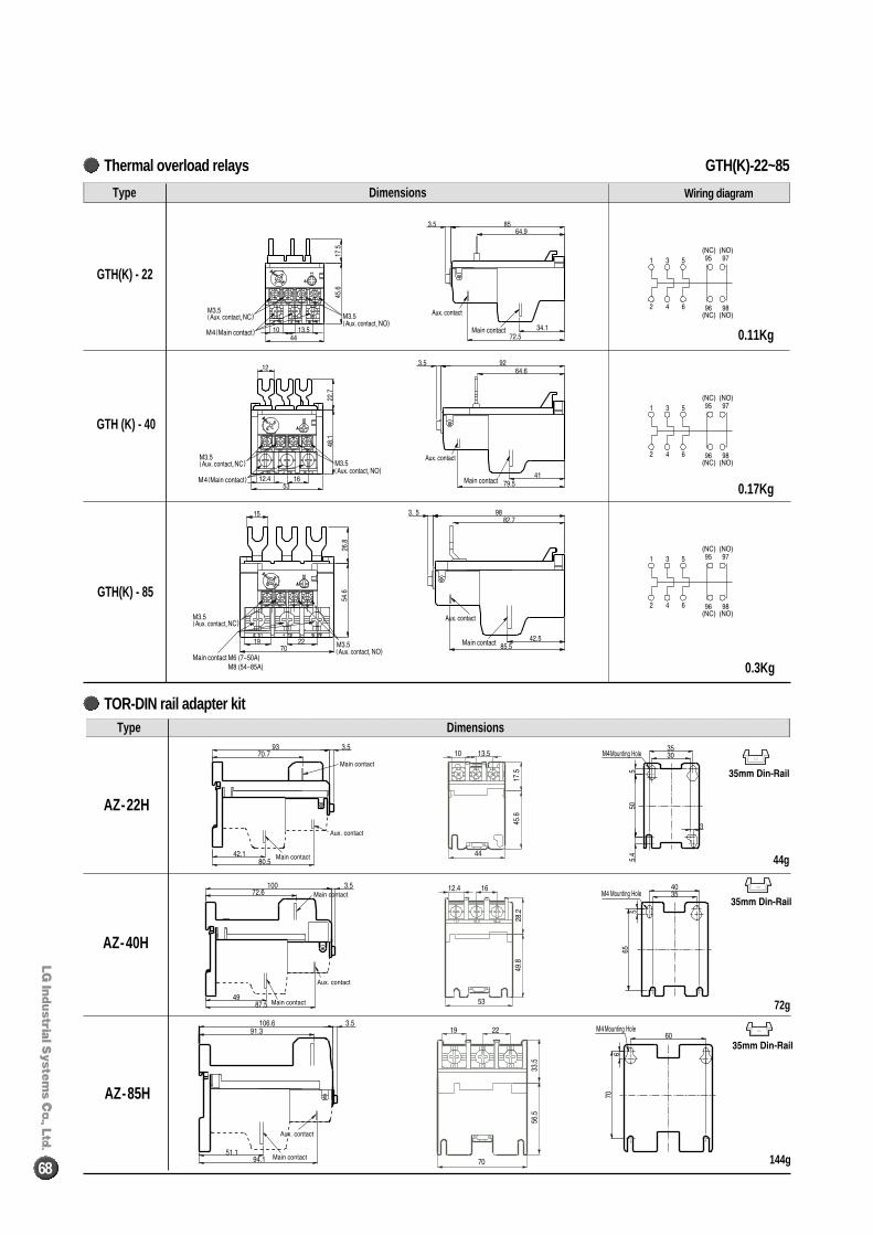
68
Type Dimensions
GTH(K) - 22
GTH (K) - 40
GTH(K) - 85
Wiring diagram
0.11Kg
0.17Kg
0.3Kg
Type Dimensions
AZ-22H
AZ-40H
AZ-85H
44g
144g
72g
GTH(K)-22~85Thermal overload relays
TOR-DIN rail adapter kit
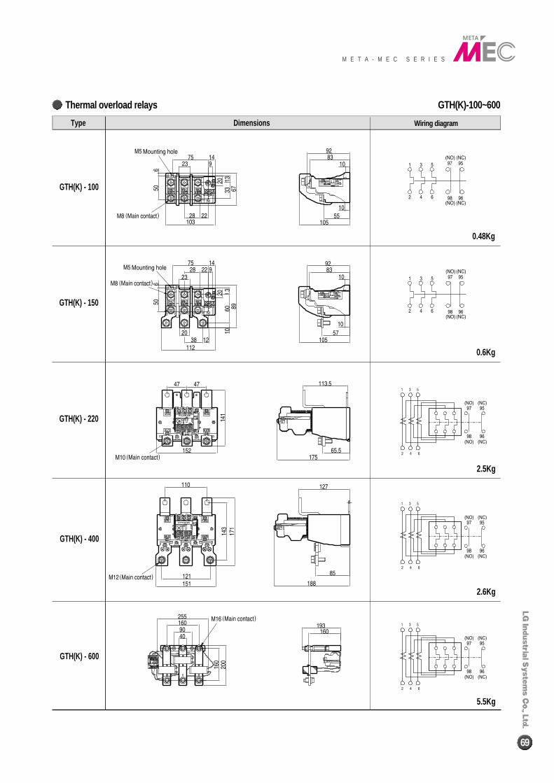
GTH(K)-100~600Thermal overload relays
M E T A - M E C S E R I E S
69
Type Dimensions
GTH(K) - 100
GTH(K) - 150
GTH(K) - 220
GTH(K) - 400
GTH(K) - 600
Wiring diagram
0.48Kg
0.6Kg
2.5Kg
2.6Kg
5.5Kg
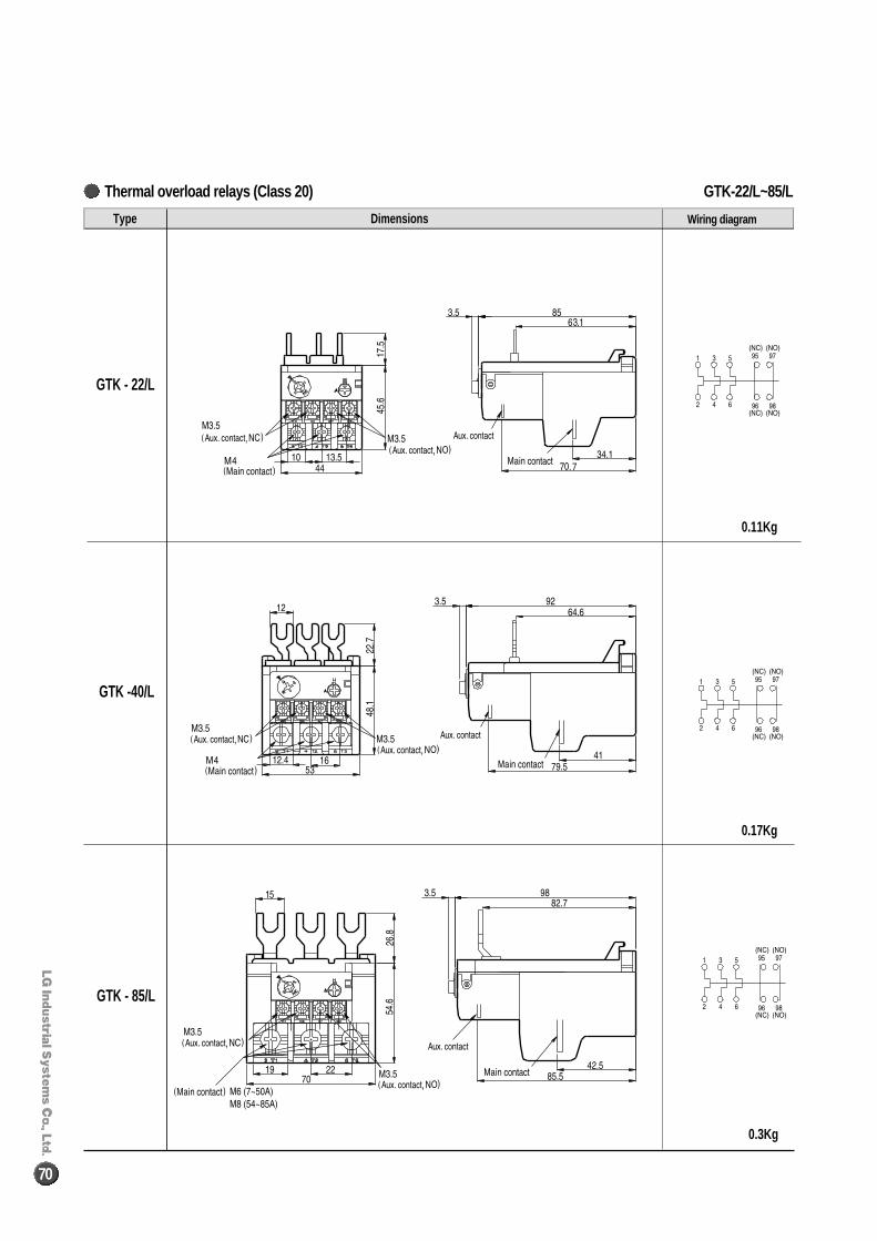
GTK-22/L~85/LThermal overload relays (Class 20)
70
Type Dimensions
GTK - 22/L
GTK -40/L
GTK - 85/L
Wiring diagram
0.11Kg
0.17Kg
0.3Kg
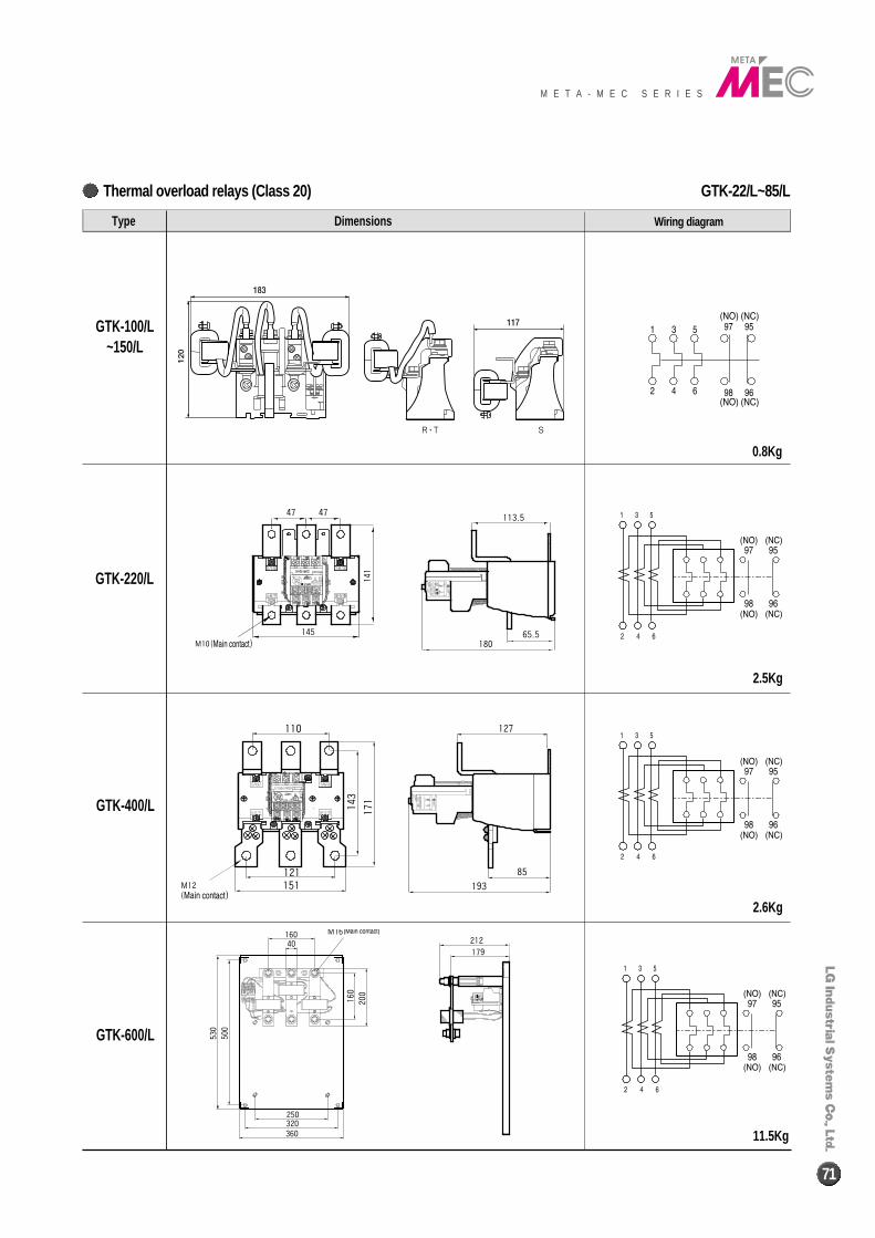
GTK-22/L~85/LThermal overload relays (Class 20)
M E T A - M E C S E R I E S
71
Type Dimensions
GTK-100/L~150/L
GTK-220/L
GTK-400/L
GTK-600/L
Wiring diagram
0.8Kg
2.5Kg
2.6Kg
11.5Kg
R∙T S
2002-10
Oct.