ControlNet User PLC-5 Programmable Manual (Cat. Nos. 1785 ...
126
User Manual Phase 1.5 ControlNet PLC-5 Programmable Controllers (Cat. Nos. 1785-L20C15, -L40C15, -L80C15) Allen-Bradley product icon
Transcript of ControlNet User PLC-5 Programmable Manual (Cat. Nos. 1785 ...
UserManualPhase 1.5
ControlNetPLC-5Programmable Controllers(Cat. Nos. 1785-L20C15,-L40C15, -L80C15)
Allen-Bradley
product icon
Important User Information 6ROLGVWDWHHTXLSPHQWKDVRSHUDWLRQDOFKDUDFWHULVWLFVGLIIHULQJIURPWKRVHRIHOHFWURPHFKDQLFDOHTXLSPHQW³6DIHW\*XLGHOLQHVIRUWKH$SSOLFDWLRQ,QVWDOODWLRQDQG0DLQWHQDQFHRI6ROLG6WDWH&RQWUROV´3XEOLFDWLRQ6*,GHVFULEHVVRPHLPSRUWDQWGLIIHUHQFHVEHWZHHQVROLGVWDWHHTXLSPHQWDQGKDUGZLUHGHOHFWURPHFKDQLFDOGHYLFHV%HFDXVHRIWKLVGLIIHUHQFHDQGDOVREHFDXVHRIWKHZLGHYDULHW\RIXVHVIRUVROLGVWDWHHTXLSPHQWDOOSHUVRQVUHVSRQVLEOHIRUDSSO\LQJWKLVHTXLSPHQWPXVWVDWLVI\WKHPVHOYHVWKDWHDFKLQWHQGHGDSSOLFDWLRQRIWKLVHTXLSPHQWLVDFFHSWDEOH
,QQRHYHQWZLOO5RFNZHOO$XWRPDWLRQEHUHVSRQVLEOHRUOLDEOHIRULQGLUHFWRUFRQVHTXHQWLDOGDPDJHVUHVXOWLQJIURPWKHXVHRUDSSOLFDWLRQRIWKLVHTXLSPHQW
7KHH[DPSOHVDQGGLDJUDPVLQWKLVPDQXDODUHLQFOXGHGVROHO\IRULOOXVWUDWLYHSXUSRVHV%HFDXVHRIWKHPDQ\YDULDEOHVDQGUHTXLUHPHQWVDVVRFLDWHGZLWKDQ\SDUWLFXODULQVWDOODWLRQ5RFNZHOO$XWRPDWLRQFDQQRWDVVXPHUHVSRQVLELOLW\RUOLDELOLW\IRUDFWXDOXVHEDVHGRQWKHH[DPSOHVDQGGLDJUDPV
1RSDWHQWOLDELOLW\LVDVVXPHGE\5RFNZHOO$XWRPDWLRQZLWKUHVSHFWWRXVHRILQIRUPDWLRQFLUFXLWVHTXLSPHQWRUVRIWZDUHGHVFULEHGLQWKLVPDQXDO
5HSURGXFWLRQRIWKHFRQWHQWVRIWKLVPDQXDOLQZKROHRULQSDUWZLWKRXWZULWWHQSHUPLVVLRQRI5RFNZHOO$XWRPDWLRQLVSURKLELWHG
7KURXJKRXWWKLVPDQXDOZHXVHQRWHVWRPDNH\RXDZDUHRIVDIHW\FRQVLGHUDWLRQV
$WWHQWLRQVKHOS\RX
LGHQWLI\DKD]DUG
DYRLGWKHKD]DUG
UHFRJQL]HWKHFRQVHTXHQFHV
,PSRUWDQW,GHQWLILHVLQIRUPDWLRQWKDWLVHVSHFLDOO\LPSRUWDQWIRUVXFFHVVIXODSSOLFDWLRQDQGXQGHUVWDQGLQJRIWKHSURGXFW
(WKHUQHWLVDUHJLVWHUHGWUDGHPDUNRI,QWHO&RUSRUDWLRQ;HUR[&RUSRUDWLRQDQG'LJLWDO(TXLSPHQW&RUSRUDWLRQ
&RQWURO1HWLVDWUDGHPDUNRI&RQWURO1HW,QWHUQDWLRQDO
'DWD+LJKZD\3OXV'+561HW:RU[)/(;,23/&3/&3/&3/&3/&&/&/&((DQG(DUHWUDGHPDUNVRI5RFNZHOO$XWRPDWLRQ
$OOHQ%UDGOH\LVDWUDGHPDUNRI5RFNZHOO$XWRPDWLRQDFRUHEXVLQHVVRI5RFNZHOO,QWHUQDWLRQDO&RUSRUDWLRQ
$77(17,21 ,GHQWLILHVLQIRUPDWLRQDERXWSUDFWLFHVRUFLUFXPVWDQFHVWKDWFDQOHDGWRSHUVRQDOLQMXU\RUGHDWKSURSHUW\GDPDJHRUHFRQRPLFORVV
Summary of Changes
Summary of Changes
7KHLQIRUPDWLRQEHORZVXPPDUL]HVWKHFKDQJHVWRWKH&RQWURO1HW3/&3URJUDPPDEOH&RQWUROOHUV8VHU0DQXDO
7RKHOS\RXILQGQHZDQGXSGDWHGLQIRUPDWLRQORRNIRUWKHUHYLVLRQEDUVDVVKRZQWRWKHOHIWRIWKLVSDUDJUDSK
New Information 7KHIROORZLQJWDEOHDQGSDUDJUDSKVGHVFULEHQHZIHDWXUHVXSGDWHGH[LVWLQJIHDWXUHVDQGZKHUHWRILQGWKLVQHZLQIRUPDWLRQ
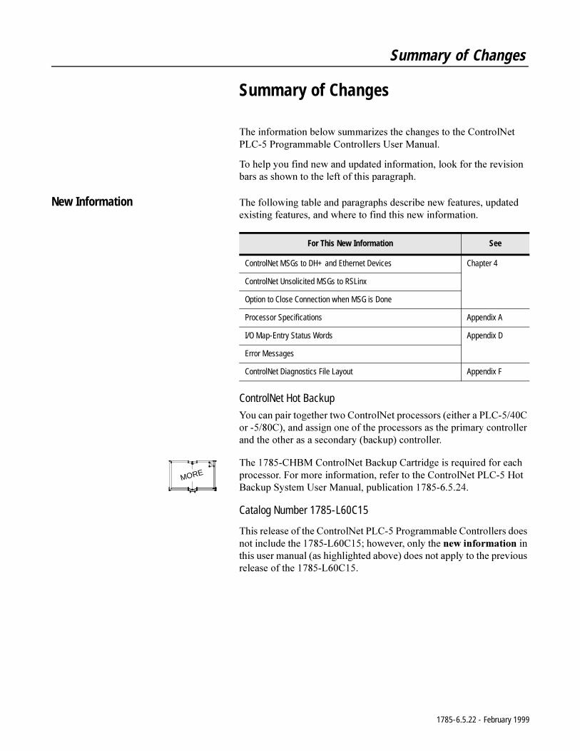
ControlNet Hot Backup
<RXFDQSDLUWRJHWKHUWZR&RQWURO1HWSURFHVVRUVHLWKHUD3/&&RU&DQGDVVLJQRQHRIWKHSURFHVVRUVDVWKHSULPDU\FRQWUROOHUDQGWKHRWKHUDVDVHFRQGDU\EDFNXSFRQWUROOHU
7KH&+%0&RQWURO1HW%DFNXS&DUWULGJHLVUHTXLUHGIRUHDFKSURFHVVRU)RUPRUHLQIRUPDWLRQUHIHUWRWKH&RQWURO1HW3/&+RW%DFNXS6\VWHP8VHU0DQXDOSXEOLFDWLRQ
Catalog Number 1785-L60C15
7KLVUHOHDVHRIWKH&RQWURO1HW3/&3URJUDPPDEOH&RQWUROOHUVGRHVQRWLQFOXGHWKH/&KRZHYHURQO\WKHQHZLQIRUPDWLRQLQWKLVXVHUPDQXDODVKLJKOLJKWHGDERYHGRHVQRWDSSO\WRWKHSUHYLRXVUHOHDVHRIWKH/&
For This New Information See
ControlNet MSGs to DH+ and Ethernet Devices Chapter 4
ControlNet Unsolicited MSGs to RSLinx
Option to Close Connection when MSG is Done
Processor Specifications Appendix A
I/O Map-Entry Status Words Appendix D
Error Messages
ControlNet Diagnostics File Layout Appendix F
MORE
1785-6.5.22 - February 1999
Preface
Preface
Introduction 7KLVPDQXDOGHVFULEHVKRZWRLQVWDOO\RXUSURFHVVRUDQGKRZWRSODQIRUFRQILJXUHDQGXVHWKHIHDWXUHVRID3/&&3/&&RU3/&&SURJUDPPDEOHFRQWUROOHUWKDWDUHXQLTXHWRWKH&RQWURO1HWQHWZRUN
:KHQZHUHIHUWR&RQWURO1HWSURFHVVRUVLQWKLVPDQXDOZHPHDQWKHSKDVHSURFHVVRUV
/&
/&
/&
)RUGHWDLOHGLQIRUPDWLRQDERXWIHDWXUHVWKDWWKH3/&&&DQG&SURJUDPPDEOHFRQWUROOHUVVKDUHZLWKWKH3/&SURFHVVRUVVHHWKH(QKDQFHGDQG(WKHUQHW3/&3URJUDPPDEOH&RQWUROOHUV8VHU0DQXDOSXEOLFDWLRQ
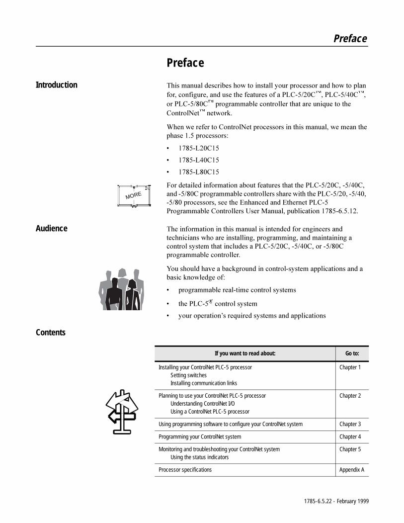
Audience 7KHLQIRUPDWLRQLQWKLVPDQXDOLVLQWHQGHGIRUHQJLQHHUVDQGWHFKQLFLDQVZKRDUHLQVWDOOLQJSURJUDPPLQJDQGPDLQWDLQLQJDFRQWUROV\VWHPWKDWLQFOXGHVD3/&&&RU&SURJUDPPDEOHFRQWUROOHU
<RXVKRXOGKDYHDEDFNJURXQGLQFRQWUROV\VWHPDSSOLFDWLRQVDQGDEDVLFNQRZOHGJHRI
SURJUDPPDEOHUHDOWLPHFRQWUROV\VWHPV
WKH3/&FRQWUROV\VWHP
\RXURSHUDWLRQ¶VUHTXLUHGV\VWHPVDQGDSSOLFDWLRQV
Contents
MORE
If you want to read about: Go to:
Installing your ControlNet PLC-5 processorSetting switchesInstalling communication links
Chapter 1
Planning to use your ControlNet PLC-5 processorUnderstanding ControlNet I/OUsing a ControlNet PLC-5 processor
Chapter 2
Using programming software to configure your ControlNet system Chapter 3
Programming your ControlNet system Chapter 4
Monitoring and troubleshooting your ControlNet systemUsing the status indicators
Chapter 5
Processor specifications Appendix A
1785-6.5.22 - February 1999
P-2 Preface
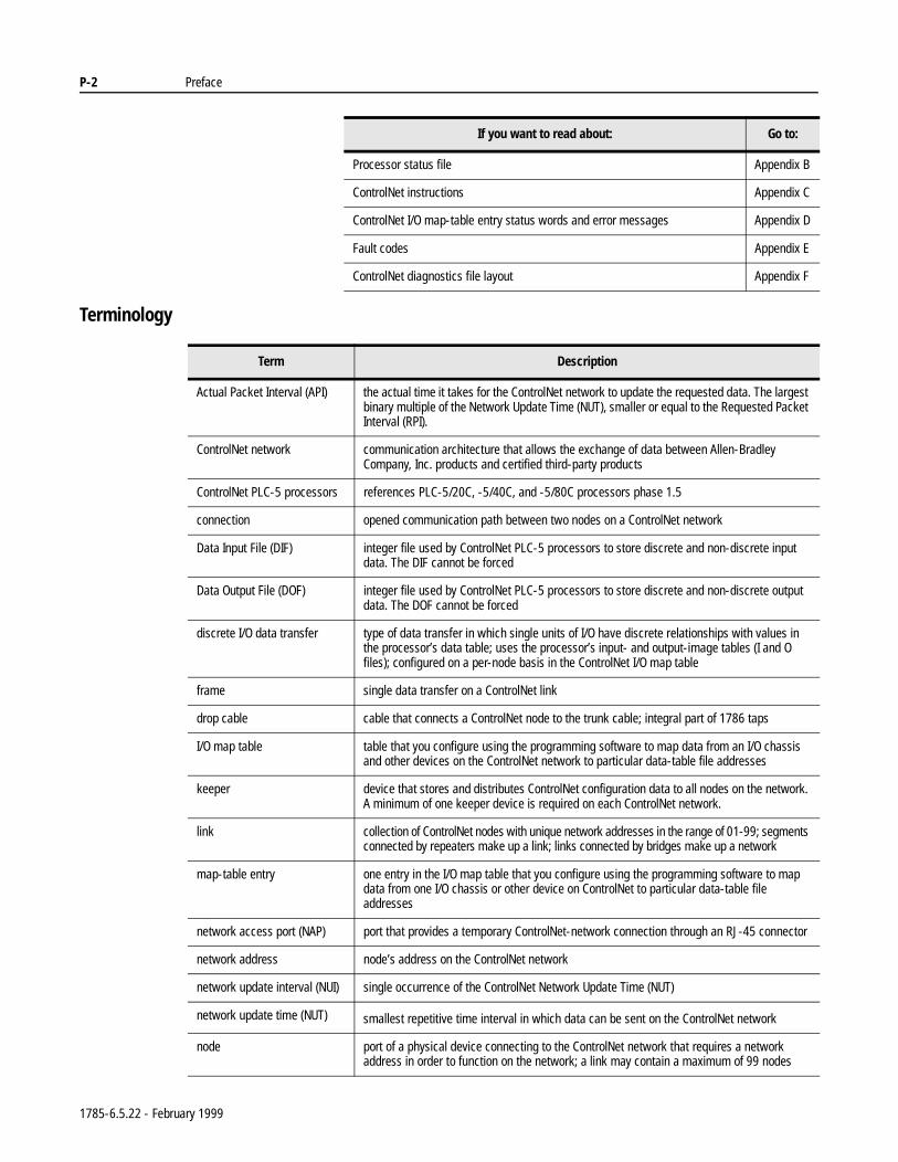
Terminology
Processor status file Appendix B
ControlNet instructions Appendix C
ControlNet I/O map-table entry status words and error messages Appendix D
Fault codes Appendix E
ControlNet diagnostics file layout Appendix F
If you want to read about: Go to:
Term Description
Actual Packet Interval (API) the actual time it takes for the ControlNet network to update the requested data. The largest binary multiple of the Network Update Time (NUT), smaller or equal to the Requested Packet Interval (RPI).
ControlNet network communication architecture that allows the exchange of data between Allen-Bradley Company, Inc. products and certified third-party products
ControlNet PLC-5 processors references PLC-5/20C, -5/40C, and -5/80C processors phase 1.5
connection opened communication path between two nodes on a ControlNet network
Data Input File (DIF) integer file used by ControlNet PLC-5 processors to store discrete and non-discrete input data. The DIF cannot be forced
Data Output File (DOF) integer file used by ControlNet PLC-5 processors to store discrete and non-discrete output data. The DOF cannot be forced
discrete I/O data transfer type of data transfer in which single units of I/O have discrete relationships with values in the processor’s data table; uses the processor’s input- and output-image tables (I and O files); configured on a per-node basis in the ControlNet I/O map table
frame single data transfer on a ControlNet link
drop cable cable that connects a ControlNet node to the trunk cable; integral part of 1786 taps
I/O map table table that you configure using the programming software to map data from an I/O chassis and other devices on the ControlNet network to particular data-table file addresses
keeper device that stores and distributes ControlNet configuration data to all nodes on the network. A minimum of one keeper device is required on each ControlNet network.
link collection of ControlNet nodes with unique network addresses in the range of 01-99; segments connected by repeaters make up a link; links connected by bridges make up a network
map-table entry one entry in the I/O map table that you configure using the programming software to map data from one I/O chassis or other device on ControlNet to particular data-table file addresses
network access port (NAP) port that provides a temporary ControlNet-network connection through an RJ-45 connector
network address node’s address on the ControlNet network
network update interval (NUI) single occurrence of the ControlNet Network Update Time (NUT)
network update time (NUT) smallest repetitive time interval in which data can be sent on the ControlNet network
node port of a physical device connecting to the ControlNet network that requires a network address in order to function on the network; a link may contain a maximum of 99 nodes
1785-6.5.22 - February 1999
Preface P-3
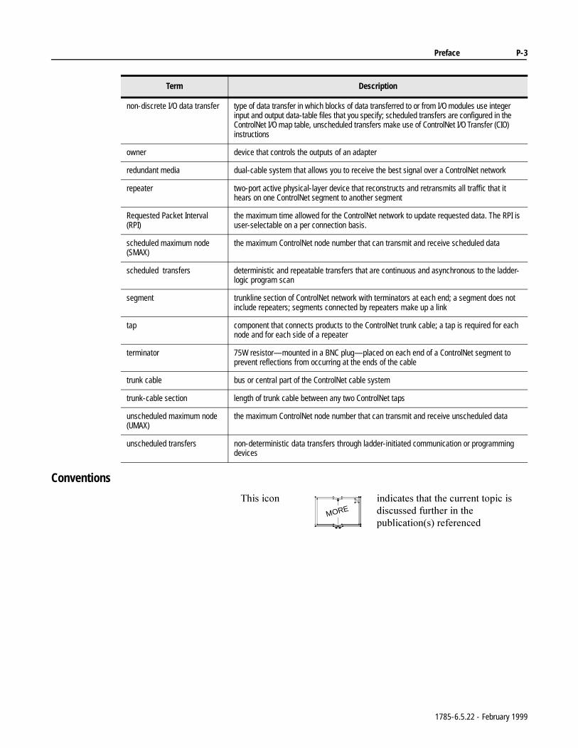
Conventions
non-discrete I/O data transfer type of data transfer in which blocks of data transferred to or from I/O modules use integer input and output data-table files that you specify; scheduled transfers are configured in the ControlNet I/O map table, unscheduled transfers make use of ControlNet I/O Transfer (CIO) instructions
owner device that controls the outputs of an adapter
redundant media dual-cable system that allows you to receive the best signal over a ControlNet network
repeater two-port active physical-layer device that reconstructs and retransmits all traffic that it hears on one ControlNet segment to another segment
Requested Packet Interval (RPI)
the maximum time allowed for the ControlNet network to update requested data. The RPI is user-selectable on a per connection basis.
scheduled maximum node (SMAX)
the maximum ControlNet node number that can transmit and receive scheduled data
scheduled transfers deterministic and repeatable transfers that are continuous and asynchronous to the ladder- logic program scan
segment trunkline section of ControlNet network with terminators at each end; a segment does not include repeaters; segments connected by repeaters make up a link
tap component that connects products to the ControlNet trunk cable; a tap is required for each node and for each side of a repeater
terminator 75W resistor—mounted in a BNC plug—placed on each end of a ControlNet segment to prevent reflections from occurring at the ends of the cable
trunk cable bus or central part of the ControlNet cable system
trunk-cable section length of trunk cable between any two ControlNet taps
unscheduled maximum node (UMAX)
the maximum ControlNet node number that can transmit and receive unscheduled data
unscheduled transfers non-deterministic data transfers through ladder-initiated communication or programming devices
Term Description
7KLVLFRQ LQGLFDWHVWKDWWKHFXUUHQWWRSLFLVGLVFXVVHGIXUWKHULQWKHSXEOLFDWLRQVUHIHUHQFHG
MORE
1785-6.5.22 - February 1999
P-4 Preface
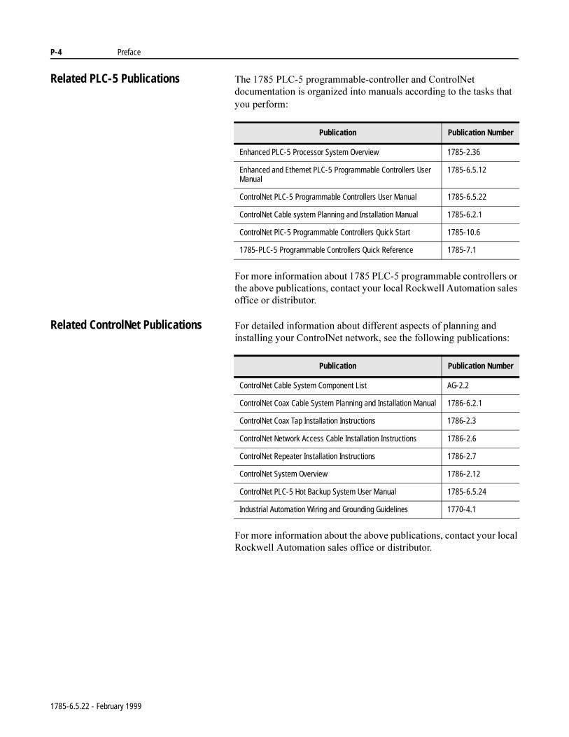
Related PLC-5 Publications 7KH3/&SURJUDPPDEOHFRQWUROOHUDQG&RQWURO1HWGRFXPHQWDWLRQLVRUJDQL]HGLQWRPDQXDOVDFFRUGLQJWRWKHWDVNVWKDW\RXSHUIRUP
)RUPRUHLQIRUPDWLRQDERXW3/&SURJUDPPDEOHFRQWUROOHUVRUWKHDERYHSXEOLFDWLRQVFRQWDFW\RXUORFDO5RFNZHOO$XWRPDWLRQVDOHVRIILFHRUGLVWULEXWRU
Related ControlNet Publications )RUGHWDLOHGLQIRUPDWLRQDERXWGLIIHUHQWDVSHFWVRISODQQLQJDQGLQVWDOOLQJ\RXU&RQWURO1HWQHWZRUNVHHWKHIROORZLQJSXEOLFDWLRQV
)RUPRUHLQIRUPDWLRQDERXWWKHDERYHSXEOLFDWLRQVFRQWDFW\RXUORFDO5RFNZHOO$XWRPDWLRQVDOHVRIILFHRUGLVWULEXWRU
Publication Publication Number
Enhanced PLC-5 Processor System Overview 1785-2.36
Enhanced and Ethernet PLC-5 Programmable Controllers User Manual
1785-6.5.12
ControlNet PLC-5 Programmable Controllers User Manual 1785-6.5.22
ControlNet Cable system Planning and Installation Manual 1785-6.2.1
ControlNet PlC-5 Programmable Controllers Quick Start 1785-10.6
1785-PLC-5 Programmable Controllers Quick Reference 1785-7.1
Publication Publication Number
ControlNet Cable System Component List AG-2.2
ControlNet Coax Cable System Planning and Installation Manual 1786-6.2.1
ControlNet Coax Tap Installation Instructions 1786-2.3
ControlNet Network Access Cable Installation Instructions 1786-2.6
ControlNet Repeater Installation Instructions 1786-2.7
ControlNet System Overview 1786-2.12
ControlNet PLC-5 Hot Backup System User Manual 1785-6.5.24
Industrial Automation Wiring and Grounding Guidelines 1770-4.1
1785-6.5.22 - February 1999
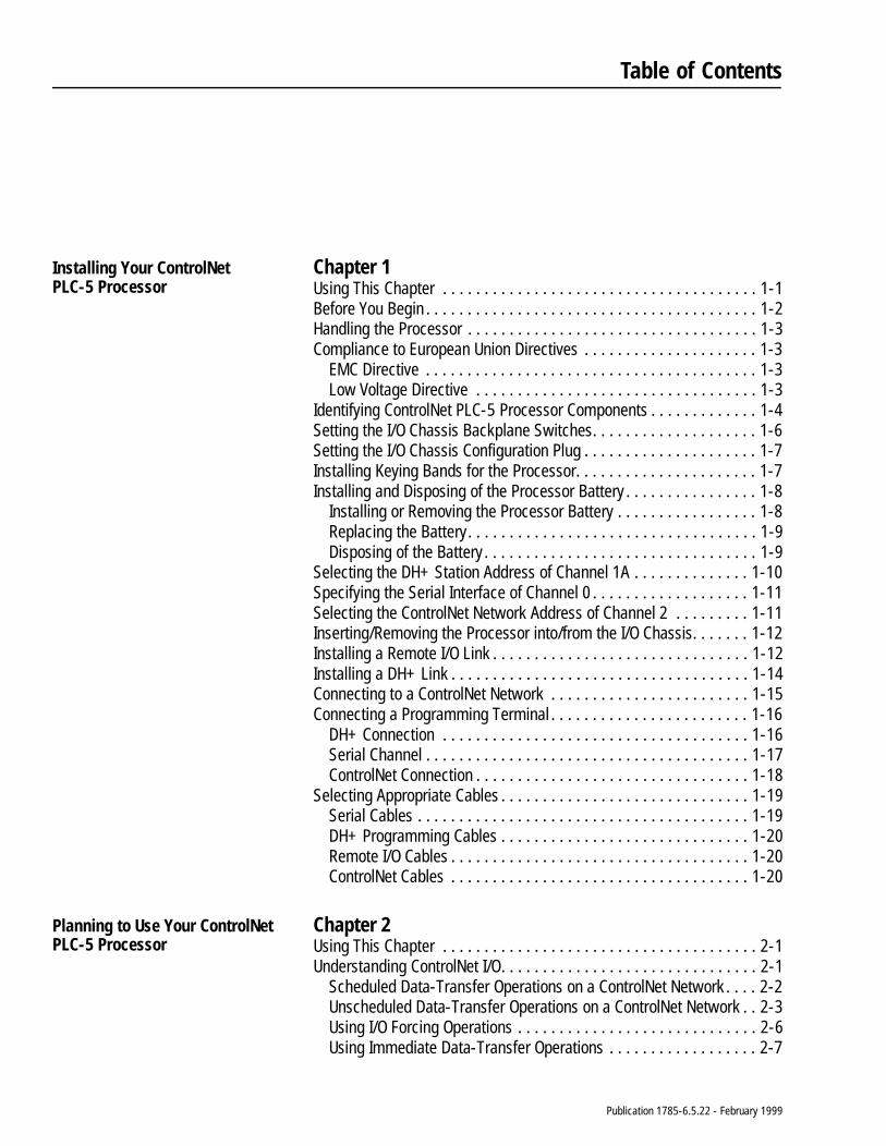
Table of Contents
Installing Your ControlNetPLC-5 Processor
Chapter 1Using This Chapter . . . . . . . . . . . . . . . . . . . . . . . . . . . . . . . . . . . . . . 1-1Before You Begin . . . . . . . . . . . . . . . . . . . . . . . . . . . . . . . . . . . . . . . . 1-2Handling the Processor . . . . . . . . . . . . . . . . . . . . . . . . . . . . . . . . . . . 1-3Compliance to European Union Directives . . . . . . . . . . . . . . . . . . . . . 1-3
EMC Directive . . . . . . . . . . . . . . . . . . . . . . . . . . . . . . . . . . . . . . . . 1-3Low Voltage Directive . . . . . . . . . . . . . . . . . . . . . . . . . . . . . . . . . . 1-3
Identifying ControlNet PLC-5 Processor Components . . . . . . . . . . . . . 1-4Setting the I/O Chassis Backplane Switches. . . . . . . . . . . . . . . . . . . . 1-6Setting the I/O Chassis Configuration Plug . . . . . . . . . . . . . . . . . . . . . 1-7Installing Keying Bands for the Processor. . . . . . . . . . . . . . . . . . . . . . 1-7Installing and Disposing of the Processor Battery . . . . . . . . . . . . . . . . 1-8
Installing or Removing the Processor Battery . . . . . . . . . . . . . . . . . 1-8Replacing the Battery. . . . . . . . . . . . . . . . . . . . . . . . . . . . . . . . . . . 1-9Disposing of the Battery . . . . . . . . . . . . . . . . . . . . . . . . . . . . . . . . . 1-9
Selecting the DH+ Station Address of Channel 1A . . . . . . . . . . . . . . 1-10Specifying the Serial Interface of Channel 0 . . . . . . . . . . . . . . . . . . . 1-11Selecting the ControlNet Network Address of Channel 2 . . . . . . . . . 1-11Inserting/Removing the Processor into/from the I/O Chassis. . . . . . . 1-12Installing a Remote I/O Link . . . . . . . . . . . . . . . . . . . . . . . . . . . . . . . 1-12Installing a DH+ Link . . . . . . . . . . . . . . . . . . . . . . . . . . . . . . . . . . . . 1-14Connecting to a ControlNet Network . . . . . . . . . . . . . . . . . . . . . . . . 1-15Connecting a Programming Terminal . . . . . . . . . . . . . . . . . . . . . . . . 1-16
DH+ Connection . . . . . . . . . . . . . . . . . . . . . . . . . . . . . . . . . . . . . 1-16Serial Channel . . . . . . . . . . . . . . . . . . . . . . . . . . . . . . . . . . . . . . . 1-17ControlNet Connection . . . . . . . . . . . . . . . . . . . . . . . . . . . . . . . . . 1-18
Selecting Appropriate Cables . . . . . . . . . . . . . . . . . . . . . . . . . . . . . . 1-19Serial Cables . . . . . . . . . . . . . . . . . . . . . . . . . . . . . . . . . . . . . . . . 1-19DH+ Programming Cables . . . . . . . . . . . . . . . . . . . . . . . . . . . . . . 1-20Remote I/O Cables . . . . . . . . . . . . . . . . . . . . . . . . . . . . . . . . . . . . 1-20ControlNet Cables . . . . . . . . . . . . . . . . . . . . . . . . . . . . . . . . . . . . 1-20
Planning to Use Your ControlNet PLC-5 Processor
Chapter 2Using This Chapter . . . . . . . . . . . . . . . . . . . . . . . . . . . . . . . . . . . . . . 2-1Understanding ControlNet I/O. . . . . . . . . . . . . . . . . . . . . . . . . . . . . . . 2-1
Scheduled Data-Transfer Operations on a ControlNet Network . . . . 2-2Unscheduled Data-Transfer Operations on a ControlNet Network . . 2-3Using I/O Forcing Operations . . . . . . . . . . . . . . . . . . . . . . . . . . . . . 2-6Using Immediate Data-Transfer Operations . . . . . . . . . . . . . . . . . . 2-7
Publication 1785-6.5.22 - February 1999
toc–ii Table of Contents – ControlNet PLC-5 Programmable Controllers
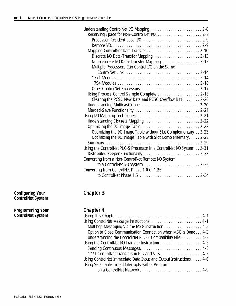
Understanding ControlNet I/O Mapping . . . . . . . . . . . . . . . . . . . . . . . 2-8Reserving Space for Non-ControlNet I/O. . . . . . . . . . . . . . . . . . . . . 2-8
Processor-Resident Local I/O . . . . . . . . . . . . . . . . . . . . . . . . . . . 2-9Remote I/O. . . . . . . . . . . . . . . . . . . . . . . . . . . . . . . . . . . . . . . . . 2-9
Mapping ControlNet Data Transfer . . . . . . . . . . . . . . . . . . . . . . . . 2-10Discrete I/O Data-Transfer Mapping . . . . . . . . . . . . . . . . . . . . . 2-13Non-discrete I/O Data-Transfer Mapping . . . . . . . . . . . . . . . . . 2-13Multiple Processors Can Control I/O on the Same
ControlNet Link . . . . . . . . . . . . . . . . . . . . . . . . . . . . . . . . . . 2-141771 Modules . . . . . . . . . . . . . . . . . . . . . . . . . . . . . . . . . . . . . 2-141794 Modules . . . . . . . . . . . . . . . . . . . . . . . . . . . . . . . . . . . . . 2-16Other ControlNet Processors . . . . . . . . . . . . . . . . . . . . . . . . . . 2-17
Using Process Control Sample Complete . . . . . . . . . . . . . . . . . . . 2-18Clearing the PCSC New Data and PCSC Overflow Bits. . . . . . . . 2-20
Understanding Multicast Inputs . . . . . . . . . . . . . . . . . . . . . . . . . . 2-20Merged-Save Functionality. . . . . . . . . . . . . . . . . . . . . . . . . . . . . . 2-21
Using I/O Mapping Techniques. . . . . . . . . . . . . . . . . . . . . . . . . . . . . 2-21Understanding Discrete Mapping . . . . . . . . . . . . . . . . . . . . . . . . . 2-22Optimizing the I/O Image Table . . . . . . . . . . . . . . . . . . . . . . . . . . 2-23
Optimizing the I/O Image Table without Slot Complementary . . 2-23Optimizing the I/O Image Table with Slot Complementary. . . . . 2-28
Summary . . . . . . . . . . . . . . . . . . . . . . . . . . . . . . . . . . . . . . . . . . . 2-29Using the ControlNet PLC-5 Processor in a ControlNet I/O System . . 2-31
Distributed Keeper Functionality. . . . . . . . . . . . . . . . . . . . . . . . . . 2-33Converting from a Non-ControlNet Remote I/O System
to a ControlNet I/O System . . . . . . . . . . . . . . . . . . . . . . . . . 2-33Converting from ControlNet Phase 1.0 or 1.25
to ControlNet Phase 1.5 . . . . . . . . . . . . . . . . . . . . . . . . . . . 2-34
Configuring Your ControlNet System
Chapter 3
Programming Your ControlNet System
Chapter 4Using This Chapter . . . . . . . . . . . . . . . . . . . . . . . . . . . . . . . . . . . . . . 4-1Using ControlNet Message Instructions . . . . . . . . . . . . . . . . . . . . . . . 4-1
Multihop Messaging Via the MSG Instruction . . . . . . . . . . . . . . . . . 4-2Option to Close Communication Connection when MSG is Done . . . 4-3Understanding the ControlNet PLC-2 Compatibility File . . . . . . . . . 4-3
Using the ControlNet I/O Transfer Instruction . . . . . . . . . . . . . . . . . . . 4-3Sending Continuous Messages. . . . . . . . . . . . . . . . . . . . . . . . . . . . 4-51771 ControlNet Transfers in PIIs and STIs. . . . . . . . . . . . . . . . . . . 4-5
Using ControlNet Immediate Data Input and Output Instructions. . . . . 4-6Using Selectable Timed Interrupts with a Program
on a ControlNet Network . . . . . . . . . . . . . . . . . . . . . . . . . . . . 4-9
Publication 1785-6.5.22 - February 1999
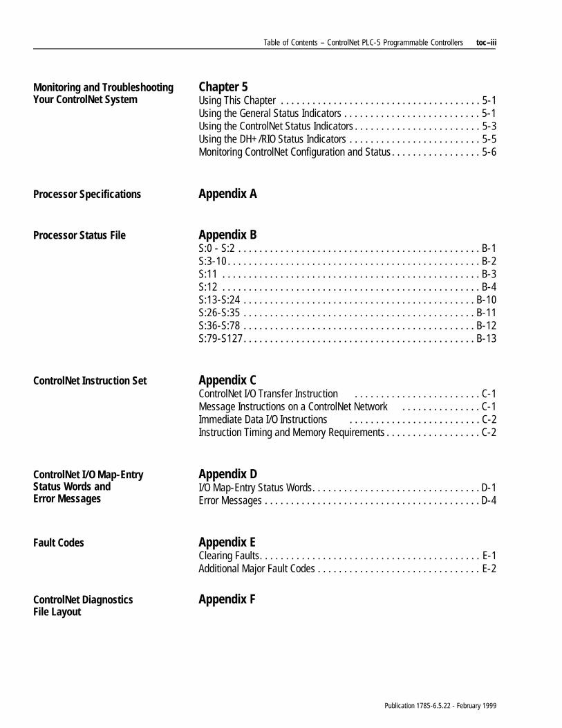
Table of Contents – ControlNet PLC-5 Programmable Controllers toc–iii
Monitoring and Troubleshooting Your ControlNet System
Chapter 5Using This Chapter . . . . . . . . . . . . . . . . . . . . . . . . . . . . . . . . . . . . . . 5-1Using the General Status Indicators . . . . . . . . . . . . . . . . . . . . . . . . . . 5-1Using the ControlNet Status Indicators . . . . . . . . . . . . . . . . . . . . . . . . 5-3Using the DH+/RIO Status Indicators . . . . . . . . . . . . . . . . . . . . . . . . . 5-5Monitoring ControlNet Configuration and Status. . . . . . . . . . . . . . . . . 5-6
Processor Specifications Appendix A
Processor Status File Appendix BS:0 - S:2 . . . . . . . . . . . . . . . . . . . . . . . . . . . . . . . . . . . . . . . . . . . . . . B-1S:3-10. . . . . . . . . . . . . . . . . . . . . . . . . . . . . . . . . . . . . . . . . . . . . . . . B-2S:11 . . . . . . . . . . . . . . . . . . . . . . . . . . . . . . . . . . . . . . . . . . . . . . . . . B-3S:12 . . . . . . . . . . . . . . . . . . . . . . . . . . . . . . . . . . . . . . . . . . . . . . . . . B-4S:13-S:24 . . . . . . . . . . . . . . . . . . . . . . . . . . . . . . . . . . . . . . . . . . . . B-10S:26-S:35 . . . . . . . . . . . . . . . . . . . . . . . . . . . . . . . . . . . . . . . . . . . . B-11S:36-S:78 . . . . . . . . . . . . . . . . . . . . . . . . . . . . . . . . . . . . . . . . . . . . B-12S:79-S127. . . . . . . . . . . . . . . . . . . . . . . . . . . . . . . . . . . . . . . . . . . . B-13
ControlNet Instruction Set Appendix CControlNet I/O Transfer Instruction . . . . . . . . . . . . . . . . . . . . . . . . C-1Message Instructions on a ControlNet Network . . . . . . . . . . . . . . . C-1Immediate Data I/O Instructions . . . . . . . . . . . . . . . . . . . . . . . . . C-2Instruction Timing and Memory Requirements . . . . . . . . . . . . . . . . . . C-2
ControlNet I/O Map-Entry Status Words and Error Messages
Appendix DI/O Map-Entry Status Words. . . . . . . . . . . . . . . . . . . . . . . . . . . . . . . . D-1Error Messages . . . . . . . . . . . . . . . . . . . . . . . . . . . . . . . . . . . . . . . . . D-4
Fault Codes Appendix EClearing Faults. . . . . . . . . . . . . . . . . . . . . . . . . . . . . . . . . . . . . . . . . . E-1Additional Major Fault Codes . . . . . . . . . . . . . . . . . . . . . . . . . . . . . . . E-2
ControlNet DiagnosticsFile Layout
Appendix F
Publication 1785-6.5.22 - February 1999
Chapter 1
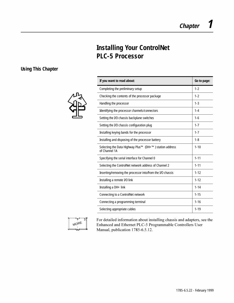
Installing Your ControlNet PLC-5 Processor
Using This Chapter
)RUGHWDLOHGLQIRUPDWLRQDERXWLQVWDOOLQJFKDVVLVDQGDGDSWHUVVHHWKH(QKDQFHGDQG(WKHUQHW3/&3URJUDPPDEOH&RQWUROOHUV8VHU0DQXDOSXEOLFDWLRQ
If you want to read about: Go to page:
Completing the preliminary setup 1-2
Checking the contents of the processor package 1-2
Handling the processor 1-3
Identifying the processor channels/connectors 1-4
Setting the I/O chassis backplane switches 1-6
Setting the I/O chassis configuration plug 1-7
Installing keying bands for the processor 1-7
Installing and disposing of the processor battery 1-8
Selecting the Data Highway Plus™ (DH+™) station address of Channel 1A
1-10
Specifying the serial interface for Channel 0 1-11
Selecting the ControlNet network address of Channel 2 1-11
Inserting/removing the processor into/from the I/O chassis 1-12
Installing a remote I/O link 1-12
Installing a DH+ link 1-14
Connecting to a ControlNet network 1-15
Connecting a programming terminal 1-16
Selecting appropriate cables 1-19
MORE
1785-6.5.22 - February 1999
1-2 Installing Your ControlNet PLC-5 Processor
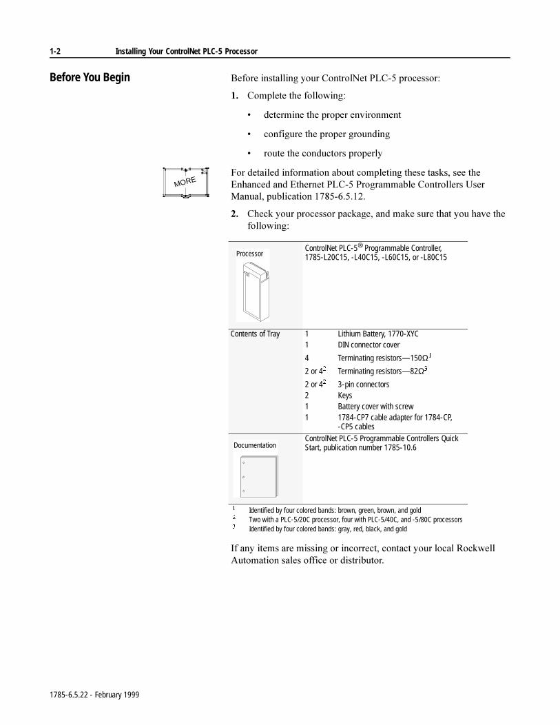
Before You Begin %HIRUHLQVWDOOLQJ\RXU&RQWURO1HW3/&SURFHVVRU
&RPSOHWHWKHIROORZLQJ
GHWHUPLQHWKHSURSHUHQYLURQPHQW
FRQILJXUHWKHSURSHUJURXQGLQJ
URXWHWKHFRQGXFWRUVSURSHUO\
)RUGHWDLOHGLQIRUPDWLRQDERXWFRPSOHWLQJWKHVHWDVNVVHHWKH(QKDQFHGDQG(WKHUQHW3/&3URJUDPPDEOH&RQWUROOHUV8VHU0DQXDOSXEOLFDWLRQ
&KHFN\RXUSURFHVVRUSDFNDJHDQGPDNHVXUHWKDW\RXKDYHWKHIROORZLQJ
,IDQ\LWHPVDUHPLVVLQJRULQFRUUHFWFRQWDFW\RXUORFDO5RFNZHOO$XWRPDWLRQVDOHVRIILFHRUGLVWULEXWRU
MORE
ControlNet PLC-5® Programmable Controller, 1785-L20C15, -L40C15, -L60C15, or -L80C15
Contents of Tray 1 Lithium Battery, 1770-XYC1 DIN connector cover
4 Terminating resistors—150Ω
2 or 4 Terminating resistors—82Ω
2 or 4 3-pin connectors2 Keys1 Battery cover with screw1 1784-CP7 cable adapter for 1784-CP,
-CP5 cablesControlNet PLC-5 Programmable Controllers Quick Start, publication number 1785-10.6
Identified by four colored bands: brown, green, brown, and gold Two with a PLC-5/20C processor, four with PLC-5/40C, and -5/80C processors Identified by four colored bands: gray, red, black, and gold
Processor
Documentation
1785-6.5.22 - February 1999
Installing Your ControlNet PLC-5 Processor 1-3
ate
lled ion.
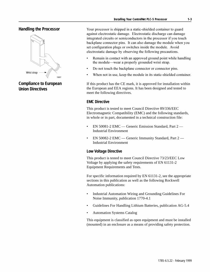
Handling the Processor <RXUSURFHVVRULVVKLSSHGLQDVWDWLFVKLHOGHGFRQWDLQHUWRJXDUGDJDLQVWHOHFWURVWDWLFGDPDJH(OHFWURVWDWLFGLVFKDUJHFDQGDPDJHLQWHJUDWHGFLUFXLWVRUVHPLFRQGXFWRUVLQWKHSURFHVVRULI\RXWRXFKEDFNSODQHFRQQHFWRUSLQV,WFDQDOVRGDPDJHWKHPRGXOHZKHQ\RXVHWFRQILJXUDWLRQSOXJVRUVZLWFKHVLQVLGHWKHPRGXOH$YRLGHOHFWURVWDWLFGDPDJHE\REVHUYLQJWKHIROORZLQJSUHFDXWLRQV
5HPDLQLQFRQWDFWZLWKDQDSSURYHGJURXQGSRLQWZKLOHKDQGOLQJWKHPRGXOH²ZHDUDSURSHUO\JURXQGHGZULVWVWUDS
'RQRWWRXFKWKHEDFNSODQHFRQQHFWRURUFRQQHFWRUSLQV
:KHQQRWLQXVHNHHSWKHPRGXOHLQLWVVWDWLFVKLHOGHGFRQWDLQHU
Compliance to European Union Directives
If this product has the CE mark, it is approved for installation within the European and EEA regions. It has been designed and tested to meet the following directives.
EMC Directive
This product is tested to meet Council Directive 89/336/EEC Electromagnetic Compatibility (EMC) and the following standards, in whole or in part, documented in a technical construction file:
• EN 50081-2 EMC — Generic Emission Standard, Part 2 — Industrial Environment
• EN 50082-2 EMC — Generic Immunity Standard, Part 2 — Industrial Environment
Low Voltage Directive
This product is tested to meet Council Directive 73/23/EEC Low Voltage by applying the safety requirements of EN 61131-2 Equipment Requirements and Tests.
For specific information required by EN 61131-2, see the approprisections in this publication as well as the following Rockwell Automation publications:
• Industrial Automation Wiring and Grounding Guidelines For Noise Immunity, publication 1770-4.1
• Guidelines For Handling Lithium Batteries, publication AG-5.4
• Automation Systems Catalog
This equipment is classified as open equipment and must be insta(mounted) in an enclosure as a means of providing safety protect
Wrist strap
19897
1785-6.5.22 - February 1999
1-4 Installing Your ControlNet PLC-5 Processor
Identifying ControlNet PLC-5 Processor Components
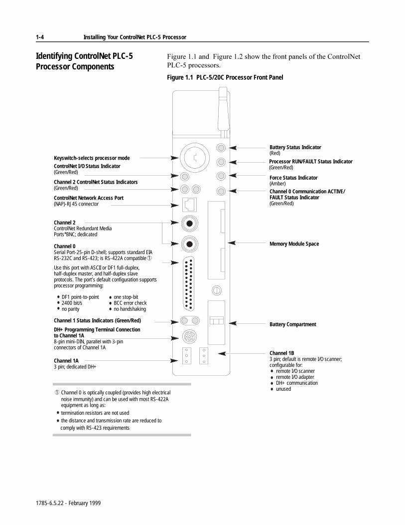
)LJXUHDQG)LJXUHVKRZWKHIURQWSDQHOVRIWKH&RQWURO1HW3/&SURFHVVRUV
Figure 1.1 PLC-5/20C Processor Front Panel
Battery Status Indicator(Red)
Processor RUN/FAULT Status Indicator(Green/Red)
Force Status Indicator(Amber)
Channel 0 Communication ACTIVE/FAULT Status Indicator(Green/Red)
Memory Module Space
Battery Compartment
Use this port with ASCII or DF1 full-duplex, half-duplex master, and half-duplex slave protocols. The port’s default configuration supports processor programming:
Keyswitch-selects processor mode
Channel 0Serial Port-25-pin D-shell; supports standard EIA RS-232C and RS-423; is RS-422A compatible
DH+ Programming Terminal Connectionto Channel 1A8-pin mini-DIN, parallel with 3-pin connectors of Channel 1A
one stop-bit BCC error check no handshaking
DF1 point-to-point 2400 bit/s no parity
Channel 2 ControlNet Status Indicators(Green/Red)
Channel 2ControlNet Redundant Media Ports*BNC; dedicated
Channel 0 is optically coupled (provides high electrical noise immunity) and can be used with most RS-422A equipment as long as: termination resistors are not used the distance and transmission rate are reduced to
comply with RS-423 requirements
ControlNet I/O Status Indicator (Green/Red)
ControlNet Network Access Port(NAP)-RJ45 connector
Channel 1 Status Indicators (Green/Red)
Channel 1A 3 pin; dedicated DH+
Channel 1B 3 pin; default is remote I/O scanner; configurable for: remote I/O scanner remote I/O adapter DH+ communication unused
1
1
1785-6.5.22 - February 1999
Installing Your ControlNet PLC-5 Processor 1-5
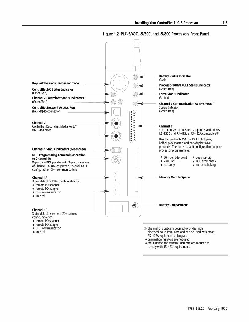
Figure 1.2 PLC-5/40C, -5/60C, and -5/80C Processors Front Panel
Battery Status Indicator(Red)
Processor RUN/FAULT Status Indicator(Green/Red)
Force Status Indicator(Amber)
Channel 0 Communication ACTIVE/FAULT Status Indicator(Green/Red)
Memory Module Space
Battery Compartment
Use this port with ASCII or DF1 full-duplex, half-duplex master, and half-duplex slave protocols. The port’s default configuration supports processor programming:
Channel 0Serial Port-25-pin D-shell; supports standard EIA RS-232C and RS-423; is RS-422A compatible
one stop-bit BCC error check no handshaking
DF1 point-to-point 2400 bps no parity
Keyswitch-selects processor mode
DH+ Programming Terminal Connectionto Channel 1A8-pin mini-DIN, parallel with 3-pin connectors of Channel 1A; use only when Channel 1A is configured for DH+ communications
Channel 2 ControlNet Redundant Media Ports* BNC; dedicated
Channel 0 is optically coupled (provides high electrical noise immunity) and can be used with most RS-422A equipment as long as:
termination resistors are not used the distance and transmission rate are reduced to
comply with RS-423 requirements
ControlNet Network Access Port(NAP)-RJ45 connector
Channel 1 Status Indicators (Green/Red)
Channel 1A 3 pin; default is DH+; configurable for: remote I/O scanner remote I/O adapter DH+ communication unused
Channel 1B3 pin; default is remote I/O scanner; configurable for: remote I/O scanner remote I/O adapter DH+ communication unused
Channel 2 ControlNet Status Indicators(Green/Red)
ControlNet I/O Status Indicator(Green/Red)
1
1
1785-6.5.22 - February 1999
1-6 Installing Your ControlNet PLC-5 Processor
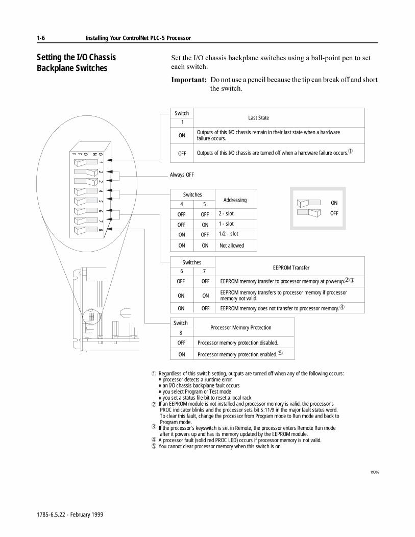
Setting the I/O Chassis Backplane Switches
6HWWKH,2FKDVVLVEDFNSODQHVZLWFKHVXVLQJDEDOOSRLQWSHQWRVHWHDFKVZLWFK
,PSRUWDQW'RQRWXVHDSHQFLOEHFDXVHWKHWLSFDQEUHDNRIIDQGVKRUWWKHVZLWFK
Regardless of this switch setting, outputs are turned off when any of the following occurs: processor detects a runtime error an I/O chassis backplane fault occurs you select Program or Test mode you set a status file bit to reset a local rack If an EEPROM module is not installed and processor memory is valid, the processor's PROC indicator blinks and the processor sets bit S:11/9 in the major fault status word. To clear this fault, change the processor from Program mode to Run mode and back to Program mode. If the processor's keyswitch is set in Remote, the processor enters Remote Run mode after it powers up and has its memory updated by the EEPROM module. A processor fault (solid red PROC LED) occurs if processor memory is not valid. You cannot clear processor memory when this switch is on.
4 5
2 - slot
1 - slot
1/2 - slot
1
Always OFF
19309
6 7
Outputs of this I/O chassis remain in their last state when a hardware failure occurs.
Outputs of this I/O chassis are turned off when a hardware failure occurs.
EEPROM memory transfer to processor memory at powerup.
EEPROM memory transfers to processor memory if processor memory not valid.
EEPROM memory does not transfer to processor memory.
Processor memory protection disabled.
Processor memory protection enabled.
Not allowed
Processor Memory ProtectionSwitch
8
OFF
ON
EEPROM Transfer
Addressing
Last StateSwitch
ON
OFF
Switches
Switches
OFF OFF
OFF ON
ON OFF
ON ON
OFF OFF
ON ON
ON OFFONOFF
12
34
56
78
ON
OFF
2
1
3
45
1
2 3
4
5
1785-6.5.22 - February 1999
Installing Your ControlNet PLC-5 Processor 1-7
Setting the I/O ChassisConfiguration Plug
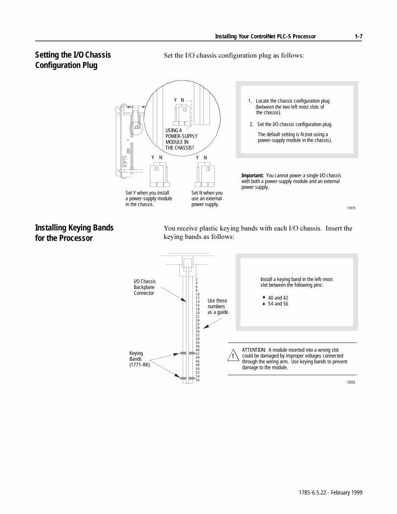
6HWWKH,2FKDVVLVFRQILJXUDWLRQSOXJDVIROORZV
Installing Keying Bandsfor the Processor
<RXUHFHLYHSODVWLFNH\LQJEDQGVZLWKHDFK,2FKDVVLV,QVHUWWKHNH\LQJEDQGVDVIROORZV
USING APOWER-SUPPLY MODULE IN THE CHASSIS?
1. Locate the chassis configuration plug (between the two left most slots of the chassis).
2. Set the I/O chassis configuration plug.
The default setting is N (not using a power-supply module in the chassis).
NY
NYNY
Set Y when you install a power-supply module in the chassis.
Set N when you use an external power supply.
Important: You cannot power a single I/O chassis with both a power-supply module and an external power supply.
17075
2468101214161820222426283032343638404244464850525456
I/O ChassisBackplaneConnector
Keying Bands(1771-RK)
Use these numbersas a guide.
12062
ATTENTION: A module inserted into a wrong slot could be damaged by improper voltages connected through the wiring arm. Use keying bands to prevent damage to the module.
!
Install a keying band in the left-most slot between the following pins:
40 and 42 54 and 56
1785-6.5.22 - February 1999
1-8 Installing Your ControlNet PLC-5 Processor
Installing and Disposing ofthe Processor Battery
7KH;<&EDWWHU\VKLSVZLWKWKHSURFHVVRUDQGUHTXLUHVVSHFLDOKDQGOLQJ
)RUPRUHGHWDLOHGLQIRUPDWLRQDERXWLQVWDOOLQJDQGGLVSRVLQJRIWKHEDWWHU\VHHWKH$OOHQ%UDGOH\*XLGHOLQHVIRU/LWKLXP%DWWHU\+DQGOLQJDQG'LVSRVDOSXEOLFDWLRQ$*
Installing or Removing the Processor Battery
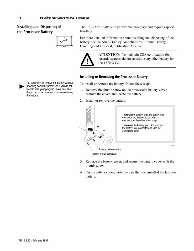
7RLQVWDOORUUHPRYHWKHEDWWHU\IROORZWKHVHVWHSV
5HPRYHWKHWKXPEVFUHZRQWKHSURFHVVRU¶VEDWWHU\FRYHUUHPRYHWKHFRYHUDQGORFDWHWKHEDWWHU\
,QVWDOORUUHPRYHWKHEDWWHU\
5HSODFHWKHEDWWHU\FRYHUDQGVHFXUHWKHEDWWHU\FRYHUZLWKWKHWKXPEVFUHZ
2QWKHEDWWHU\FRYHUZULWHWKHGDWHWKDW\RXLQVWDOOHGWKHODVWQHZEDWWHU\
MORE
$77(17,21 7RPDLQWDLQ&6$FHUWLILFDWLRQIRUKD]DUGRXVDUHDVGRQRWVXEVWLWXWHDQ\RWKHUEDWWHU\IRUWKH;<&
You can insert or remove the battery without powering down the processor. If you do not want to lose your program, make sure that the processor is powered on when removing the battery.
+-
To install the battery, slide the battery-side connector into the processor-side connector until you hear them snap.
To remove the battery, press the lever on the battery-side connector and slide the connectors apart.
19331
Battery-side connector
Processor-side connector
1785-6.5.22 - February 1999
Installing Your ControlNet PLC-5 Processor 1-9
Replacing the Battery
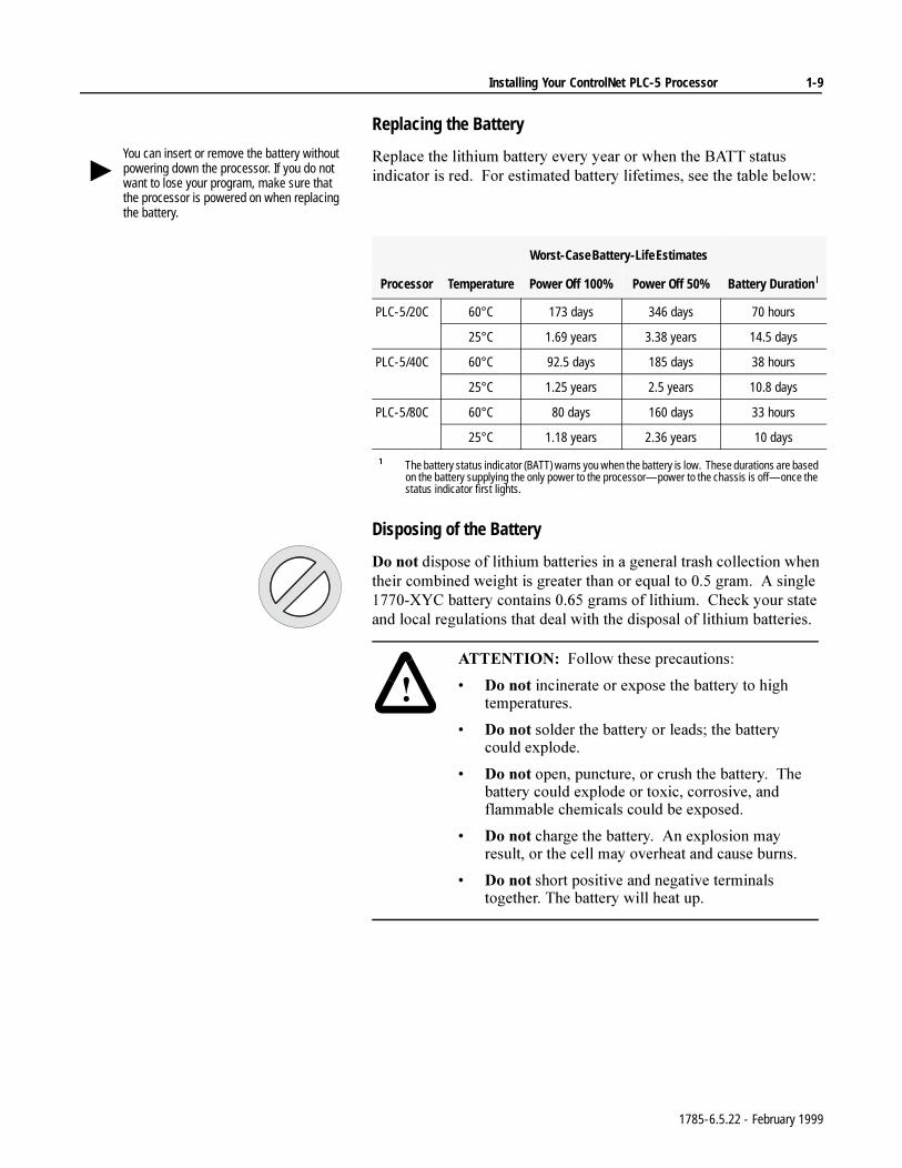
5HSODFHWKHOLWKLXPEDWWHU\HYHU\\HDURUZKHQWKH%$77VWDWXVLQGLFDWRULVUHG)RUHVWLPDWHGEDWWHU\OLIHWLPHVVHHWKHWDEOHEHORZ
Disposing of the Battery
'RQRWGLVSRVHRIOLWKLXPEDWWHULHVLQDJHQHUDOWUDVKFROOHFWLRQZKHQWKHLUFRPELQHGZHLJKWLVJUHDWHUWKDQRUHTXDOWRJUDP$VLQJOH;<&EDWWHU\FRQWDLQVJUDPVRIOLWKLXP&KHFN\RXUVWDWHDQGORFDOUHJXODWLRQVWKDWGHDOZLWKWKHGLVSRVDORIOLWKLXPEDWWHULHV
You can insert or remove the battery without powering down the processor. If you do not want to lose your program, make sure that the processor is powered on when replacing the battery.
Worst-Case Battery-Life Estimates
Processor Temperature Power Off 100% Power Off 50% Battery Duration
PLC-5/20C 60°C 173 days 346 days 70 hours
25°C 1.69 years 3.38 years 14.5 days
PLC-5/40C 60°C 92.5 days 185 days 38 hours
25°C 1.25 years 2.5 years 10.8 days
PLC-5/80C 60°C 80 days 160 days 33 hours
25°C 1.18 years 2.36 years 10 days
The battery status indicator (BATT) warns you when the battery is low. These durations are based on the battery supplying the only power to the processor—power to the chassis is off—once the status indicator first lights.
$77(17,21 )ROORZWKHVHSUHFDXWLRQV
'RQRWLQFLQHUDWHRUH[SRVHWKHEDWWHU\WRKLJKWHPSHUDWXUHV
'RQRWVROGHUWKHEDWWHU\RUOHDGVWKHEDWWHU\FRXOGH[SORGH
'RQRWRSHQSXQFWXUHRUFUXVKWKHEDWWHU\7KHEDWWHU\FRXOGH[SORGHRUWR[LFFRUURVLYHDQGIODPPDEOHFKHPLFDOVFRXOGEHH[SRVHG
'RQRWFKDUJHWKHEDWWHU\$QH[SORVLRQPD\UHVXOWRUWKHFHOOPD\RYHUKHDWDQGFDXVHEXUQV
'RQRWVKRUWSRVLWLYHDQGQHJDWLYHWHUPLQDOVWRJHWKHU7KHEDWWHU\ZLOOKHDWXS
1785-6.5.22 - February 1999
1-10 Installing Your ControlNet PLC-5 Processor
Selecting the DH+ Station Address of Channel 1A
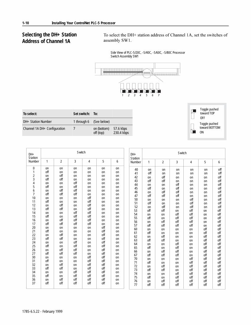
7RVHOHFWWKH'+VWDWLRQDGGUHVVRI&KDQQHO$VHWWKHVZLWFKHVRIDVVHPEO\6:
Side View of PLC-5/20C, -5/40C, -5/60C, -5/80C Processor Switch Assembly SW1
1 2 3 4 5 6 7
To select: Set switch: To:
DH+ Station Number 1 through 6 (See below)
Channel 1A DH+ Configuration 7 on (bottom)off (top)
57.6 kbps230.4 kbps
Toggle pushed
ON
Toggle pushed
OFF
toward BOTTOM
toward TOP
StationNumber
01234567
1011121314151617202122232425
1
onoffonoffonoffonoffonoffonoffonoffonoffonoffonoffonoff
2
ononoffoffononoffoffononoffoffononoffoffononoffoffonon
3
ononononoffoffoffoffononononoffoffoffoffononononoffoff
4
ononononononononoffoffoffoffoffoffoffoffonononononon
5
ononononononononononononononononoffoffoffoffoffoff
6
onononononononononononononononononononononon
424344454647505152
onoffonoffonoffonoffon
offoffononoffoffononoff
ononoffoffoffoffononon
ononononononoffoffoff
ononononononononon
offoffoffoffoffoffoffoffoff
Switch
StationNumber
535455565760616263646566677071727374757677
1
offonoffonoffonoffonoffonoffonoffonoffonoffonoffonoff
2
offononoffoffononoffoffononoffoffononoffoffononoffoff
3
onoffoffoffoffononononoffoffoffoffononononoffoffoffoff
4
offoffoffoffoffononononononononoffoffoffoffoffoffoffoff
5
onononononoffoffoffoffoffoffoffoffoffoffoffoffoffoffoffoff
6
offoffoffoffoffoffoffoffoffoffoffoffoffoffoffoffoffoffoffoffoff
Switch
26273031323334353637
4041
onoffonoffonoffonoffonoff
onoff
offoffononoffoffononoffoff
onon
offoffononononoffoffoffoff
onon
ononoffoffoffoffoffoffoffoff
onon
offoffoffoffoffoffoffoffoffoff
onon
onononononononononon
offoff
DH+ DH+
1785-6.5.22 - February 1999
Installing Your ControlNet PLC-5 Processor 1-11
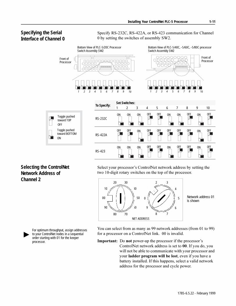
Specifying the Serial Interface of Channel 0
6SHFLI\56&56$RU56FRPPXQLFDWLRQIRU&KDQQHOE\VHWWLQJWKHVZLWFKHVRIDVVHPEO\6:
Selecting the ControlNetNetwork Address ofChannel 2
6HOHFW\RXUSURFHVVRU¶V&RQWURO1HWQHWZRUNDGGUHVVE\VHWWLQJWKHWZRGLJLWURWDU\VZLWFKHVRQWKHWRSRIWKHSURFHVVRU
<RXFDQVHOHFWIURPDVPDQ\DVQHWZRUNDGGUHVVHVIURPWRIRUDSURFHVVRURQD&RQWURO1HWOLQNLVLQYDOLG
,PSRUWDQW'RQRWSRZHUXSWKHSURFHVVRULIWKHSURFHVVRU¶V&RQWURO1HWQHWZRUNDGGUHVVLVVHWWR,I\RXGR\RXZLOOQRWEHDEOHWRFRPPXQLFDWHZLWK\RXUSURFHVVRUDQG\RXUODGGHUSURJUDPZLOOEHORVWHYHQLI\RXKDYHDEDWWHU\LQVWDOOHG,IWKLVKDSSHQVVHOHFWDYDOLGQHWZRUNDGGUHVVIRUWKHSURFHVVRUDQGF\FOHSRZHU
Front ofProcessor
Front ofProcessor
Bottom View of PLC-5/20C ProcessorSwitch Assembly SW2
Bottom View of PLC-5/40C, -5/60C, -5/80C processor Switch Assembly SW2
1 2 3 4 5 6 7 8 9 10 1 2 3 4 5 6 7 8 9 10
To Specify:Set Switches:1 2 3 4 5 6 7 8 9 10
RS-232C
RS-422A
RS-423
Toggle pushed
ON
Toggle pushed
OFF
toward BOTTOM
toward TOP
ON ON ON OFF OFF ON ON OFF ON OFF
OFF OFF ON OFF OFF OFF OFF OFF ON OFF
ON ON ON OFF OFF ON OFF OFF ON OFF
00
10
20 30
40
50
60
7080
90
0
1
2 3
4
5
6
78
9
NET ADDRESS
Network address 01is shown
For optimum throughput, assign addresses to your ControlNet nodes in a sequential order starting with 01 for the keeper processor.
1785-6.5.22 - February 1999
1-12 Installing Your ControlNet PLC-5 Processor
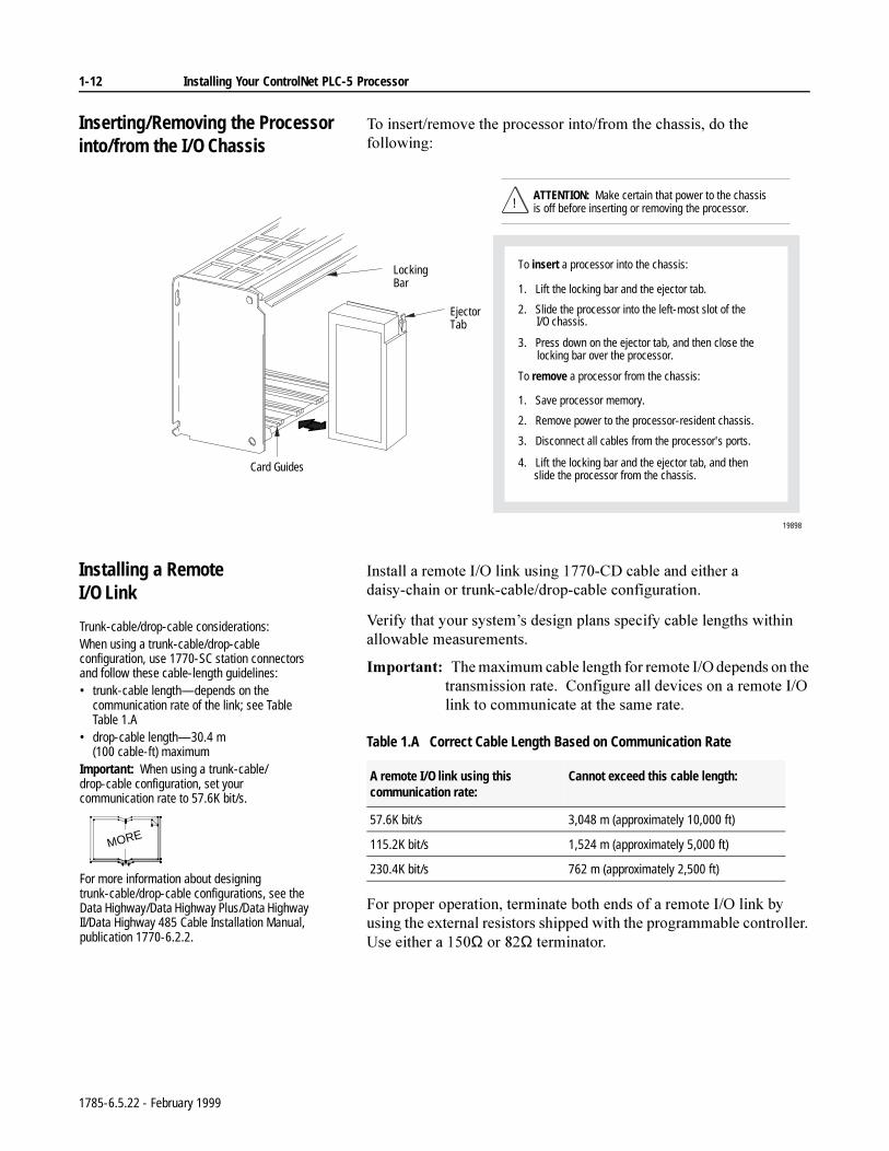
Inserting/Removing the Processor into/from the I/O Chassis
7RLQVHUWUHPRYHWKHSURFHVVRULQWRIURPWKHFKDVVLVGRWKHIROORZLQJ
Installing a Remote I/O Link
,QVWDOODUHPRWH,2OLQNXVLQJ&'FDEOHDQGHLWKHUDGDLV\FKDLQRUWUXQNFDEOHGURSFDEOHFRQILJXUDWLRQ
9HULI\WKDW\RXUV\VWHP¶VGHVLJQSODQVVSHFLI\FDEOHOHQJWKVZLWKLQDOORZDEOHPHDVXUHPHQWV
,PSRUWDQW7KHPD[LPXPFDEOHOHQJWKIRUUHPRWH,2GHSHQGVRQWKHWUDQVPLVVLRQUDWH&RQILJXUHDOOGHYLFHVRQDUHPRWH,2OLQNWRFRPPXQLFDWHDWWKHVDPHUDWH
Table 1.A Correct Cable Length Based on Communication Rate
)RUSURSHURSHUDWLRQWHUPLQDWHERWKHQGVRIDUHPRWH,2OLQNE\XVLQJWKHH[WHUQDOUHVLVWRUVVKLSSHGZLWKWKHSURJUDPPDEOHFRQWUROOHU8VHHLWKHUDΩRUΩWHUPLQDWRU
To insert a processor into the chassis:
1. Lift the locking bar and the ejector tab.
2. Slide the processor into the left-most slot of the I/O chassis.
3. Press down on the ejector tab, and then close the locking bar over the processor.
To remove a processor from the chassis:
1. Save processor memory.
2. Remove power to the processor-resident chassis.
3. Disconnect all cables from the processor's ports.
4. Lift the locking bar and the ejector tab, and then slide the processor from the chassis.
19898
ATTENTION: Make certain that power to the chassis is off before inserting or removing the processor.
EjectorTab
Locking Bar
Card Guides
!
Trunk-cable/drop-cable considerations:When using a trunk-cable/drop-cable configuration, use 1770-SC station connectors and follow these cable-length guidelines:• trunk-cable length—depends on the
communication rate of the link; see Table Table 1.A
• drop-cable length—30.4 m (100 cable-ft) maximum
Important: When using a trunk-cable/ drop-cable configuration, set your communication rate to 57.6K bit/s.
For more information about designing trunk-cable/drop-cable configurations, see the Data Highway/Data Highway Plus/Data Highway II/Data Highway 485 Cable Installation Manual, publication 1770-6.2.2.
MORE
A remote I/O link using this communication rate:
Cannot exceed this cable length:
57.6K bit/s 3,048 m (approximately 10,000 ft)
115.2K bit/s 1,524 m (approximately 5,000 ft)
230.4K bit/s 762 m (approximately 2,500 ft)
1785-6.5.22 - February 1999
Installing Your ControlNet PLC-5 Processor 1-13
If your remote I/O link:
Use this resistor rating:
The maximum number of
physical devices that you can connect on the link is:
logical rack numbers that you can scan on the link is:
Operates at 230.4K bit/s
82Ω 32 16
Operates at 57.6K or 115.2K bit/s, and no devices listed below are linkedScanners 1771-SN; 1772-SD, -SD2;
1775-SR, -S4A, -S4B; 6008-SQH1, -SQH2
Adapters 1771-AS; 1771-ASB (Series A Only); 1771-DCMMiscellaneous 1771-AF
Connects to any device listed below:Scanners 1771-SN; 1772-SD, -SD2;
1775-SR, -S4A, -S4B; 6008-SQH1, -SQH2
Adapters 1771-AS; 1771-ASB (Series A Only); 1771-DCMMiscellaneous 1771-AF
150Ω 16 16
Operates at 57.6K or 115.2K bit/s, and you do not require over 16 physical devices
PLC-5/40C, -5/60C, -5/80C Processor
PLC-5/20CProcessor
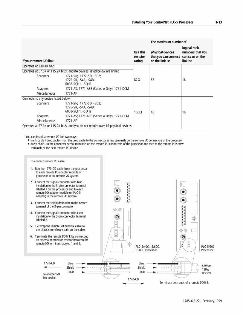
To connect remote I/O cable:
1. Run the 1770-CD cable from the processor to each remote I/O adapter module or processor in the remote I/O system.
2. Connect the signal conductor with blue insulation to the 3-pin connector terminal labeled 1 on the processor and to each remote I/O adapter module (or PLC-5 adapter) in the remote I/O system.
3. Connect the shield drain wire to the center terminal of the 3-pin connector.
4. Connect the signal conductor with clear insulation to the 3-pin connector terminal labeled 2.
5. Tie wrap the remote I/O network cable to the chassis to relieve strain on the cable.
6. Terminate the remote I/O link by connecting an external terminator resistor between the remote I/O terminals labeled 1 and 2.
To another I/O link device
1770-CD
ClearShieldBlue
82W or 150W resistorClear
ShieldBlue
Terminate both ends of a remote I/O link1770-CD
You can install a remote I/O link two ways: trunk cable / drop cable--from the drop cable to the connector screw terminals on the remote I/O connectors of the processor daisy chain--to the connector screw terminals on the remote I/O connectors of the processor and then to the remote I/O screw
terminals of the next remote I/O device
1785-6.5.22 - February 1999
1-14 Installing Your ControlNet PLC-5 Processor
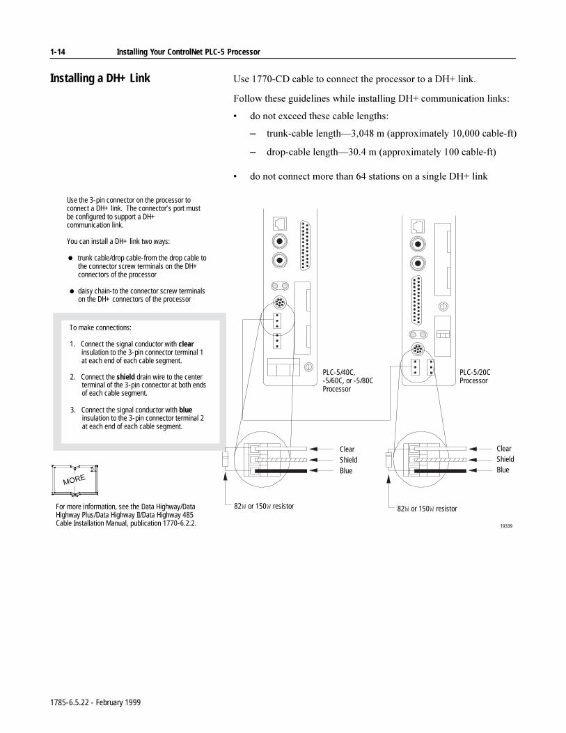
Installing a DH+ Link 8VH&'FDEOHWRFRQQHFWWKHSURFHVVRUWRD'+OLQN
)ROORZWKHVHJXLGHOLQHVZKLOHLQVWDOOLQJ'+FRPPXQLFDWLRQOLQNV
GRQRWH[FHHGWKHVHFDEOHOHQJWKV
± WUXQNFDEOHOHQJWK²PDSSUR[LPDWHO\FDEOHIW
± GURSFDEOHOHQJWK²PDSSUR[LPDWHO\FDEOHIW
GRQRWFRQQHFWPRUHWKDQVWDWLRQVRQDVLQJOH'+OLQN
19339
82W or 150W resistor
ClearShieldBlue
ClearShieldBlue
82W or 150W resistor
Use the 3-pin connector on the processor to connect a DH+ link. The connector’s port must be configured to support a DH+ communication link.
You can install a DH+ link two ways:
trunk cable/drop cable-from the drop cable to the connector screw terminals on the DH+ connectors of the processor
daisy chain-to the connector screw terminals on the DH+ connectors of the processor
To make connections:
1. Connect the signal conductor with clear insulation to the 3-pin connector terminal 1 at each end of each cable segment.
2. Connect the shield drain wire to the center terminal of the 3-pin connector at both ends of each cable segment.
3. Connect the signal conductor with blue insulation to the 3-pin connector terminal 2 at each end of each cable segment.
PLC-5/40C, -5/60C, or -5/80CProcessor
PLC-5/20CProcessor
For more information, see the Data Highway/Data Highway Plus/Data Highway II/Data Highway 485 Cable Installation Manual, publication 1770-6.2.2.
MORE
1785-6.5.22 - February 1999
Installing Your ControlNet PLC-5 Processor 1-15
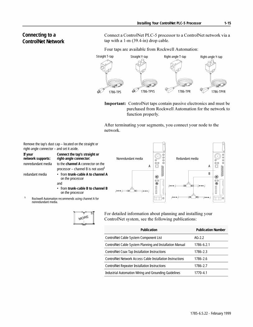
Connecting to a ControlNet Network
&RQQHFWD&RQWURO1HW3/&SURFHVVRUWRD&RQWURO1HWQHWZRUNYLDDWDSZLWKDPLQGURSFDEOH
)RXUWDSVDUHDYDLODEOHIURP5RFNZHOO$XWRPDWLRQ
,PSRUWDQW&RQWURO1HWWDSVFRQWDLQSDVVLYHHOHFWURQLFVDQGPXVWEHSXUFKDVHGIURP5RFNZHOO$XWRPDWLRQIRUWKHQHWZRUNWRIXQFWLRQSURSHUO\
$IWHUWHUPLQDWLQJ\RXUVHJPHQWV\RXFRQQHFW\RXUQRGHWRWKHQHWZRUN
)RUGHWDLOHGLQIRUPDWLRQDERXWSODQQLQJDQGLQVWDOOLQJ\RXU&RQWURO1HWV\VWHPVHHWKHIROORZLQJSXEOLFDWLRQV
Straight T-tap
1786-TPS
Straight Y-tap
1786-TPYS
Right-angle T-tap
1786-TPR
Right-angle Y-tap
1786-TPYR
Remove the tap’s dust cap – located on the straight or right-angle connector – and set it aside.
If yournetwork supports:
Connect the tap’s straight or right-angle connector:
nonredundant media to the channel A connector on the processor – channel B is not used
redundant media • from trunk-cable A to channel A on the processor
and• from trunk-cable B to channel B
on the processor Rockwell Automation recommends using channel A for
nonredundant media.
CH 0A
B
Redundant media
BATT
CH 0A
Nonredundant media
MORE
Publication Publication Number
ControlNet Cable System Component List AG-2.2
ControlNet Cable System Planning and Installation Manual 1786-6.2.1
ControlNet Coax Tap Installation Instructions 1786-2.3
ControlNet Network Access Cable Installation Instructions 1786-2.6
ControlNet Repeater Installation Instructions 1786-2.7
Industrial Automation Wiring and Grounding Guidelines 1770-4.1
1785-6.5.22 - February 1999
1-16 Installing Your ControlNet PLC-5 Processor
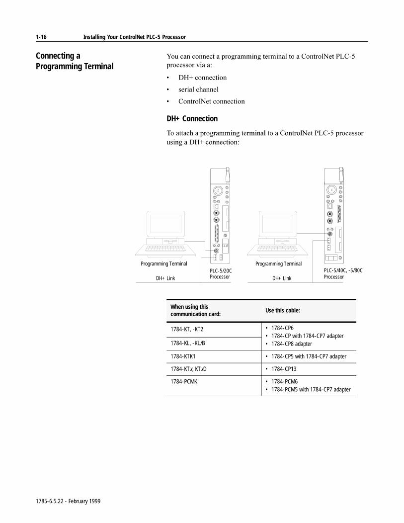
Connecting a Programming Terminal
<RXFDQFRQQHFWDSURJUDPPLQJWHUPLQDOWRD&RQWURO1HW3/&SURFHVVRUYLDD
'+FRQQHFWLRQ
VHULDOFKDQQHO
&RQWURO1HWFRQQHFWLRQ
DH+ Connection
7RDWWDFKDSURJUDPPLQJWHUPLQDOWRD&RQWURO1HW3/&SURFHVVRUXVLQJD'+FRQQHFWLRQ
CH 0
Programming TerminalPLC-5/20CProcessorDH+ Link
Programming Terminal
DH+ Link
PLC-5/40C, -5/80CProcessor
When using this communication card:
Use this cable:
1784-KT, -KT2 • 1784-CP6• 1784-CP with 1784-CP7 adapter• 1784-CP8 adapter1784-KL, -KL/B
1784-KTK1 • 1784-CP5 with 1784-CP7 adapter
1784-KTx, KTxD • 1784-CP13
1784-PCMK • 1784-PCM6• 1784-PCM5 with 1784-CP7 adapter
1785-6.5.22 - February 1999
Installing Your ControlNet PLC-5 Processor 1-17
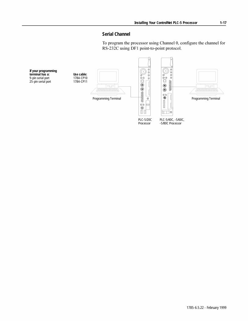
Serial Channel
7RSURJUDPWKHSURFHVVRUXVLQJ&KDQQHOFRQILJXUHWKHFKDQQHOIRU56&XVLQJ')SRLQWWRSRLQWSURWRFRO
Programming Terminal
PLC-5/40C, -5/60C, -5/80C Processor
PLC-5/20CProcessor
Programming Terminal
If your programming terminal has a: Use cable:9-pin serial port 1784-CP1025-pin serial port 1784-CP11
1785-6.5.22 - February 1999
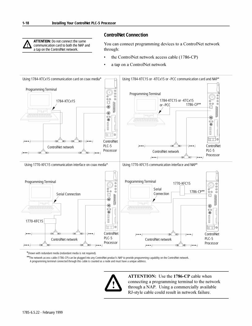
1-18 Installing Your ControlNet PLC-5 Processor
ControlNet Connection
<RXFDQFRQQHFWSURJUDPPLQJGHYLFHVWRD&RQWURO1HWQHWZRUNWKURXJK
WKH&RQWURO1HWQHWZRUNDFFHVVFDEOH&3
DWDSRQD&RQWURO1HWQHWZRUN
ATTENTION: Do not connect the same communication card to both the NAP and a tap on the ControlNet network.
!
BATT
CH 0
BATT
CH 0
BATT
CH 0
BATT
CH 0
Using 1784-KTCx15 communication card on coax media* Using 1784-KTC15 or -KTCx15 or -PCC communication card and NAP*
Programming Terminal
1784-KTCx15
ControlNet network
ControlNetPLC-5Processor
ControlNetPLC-5Processor
ControlNetPLC-5Processor
ControlNetPLC-5Processor
ControlNet network
ControlNet network ControlNet network
Programming Terminal Programming Terminal
Programming Terminal
Serial Connection
1784-KTC15 or -KTCx15or -PCC 1786-CP**
Using 1770-KFC15 communication interface and NAP*Using 1770-KFC15 communication interface on coax media*
1786-CP**
1770-KFC15
SerialConnection
1770-KFC15
*Shown with redundant media (redundant media is not required).
**The network access cable (1786-CP) can be plugged into any ControlNet product’s NAP to provide programming capability on the ControlNet network. A programming terminal connected through this cable is counted as a node and must have a unique address.
$77(17,21 8VHWKH&3FDEOHZKHQFRQQHFWLQJDSURJUDPPLQJWHUPLQDOWRWKHQHWZRUNWKURXJKD1$38VLQJDFRPPHUFLDOO\DYDLODEOH5-VW\OHFDEOHFRXOGUHVXOWLQQHWZRUNIDLOXUH
1785-6.5.22 - February 1999
Installing Your ControlNet PLC-5 Processor 1-19
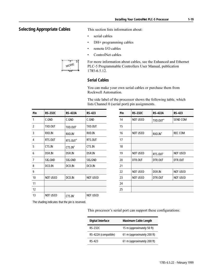
Selecting Appropriate Cables 7KLVVHFWLRQOLVWVLQIRUPDWLRQDERXW
VHULDOFDEOHV
'+SURJUDPPLQJFDEOHV
UHPRWH,2FDEOHV
&RQWURO1HWFDEOHV
)RUPRUHLQIRUPDWLRQDERXWFDEOHVVHHWKH(QKDQFHGDQG(WKHUQHW3/&3URJUDPPDEOH&RQWUROOHUV8VHU0DQXDOSXEOLFDWLRQ
Serial Cables
<RXFDQPDNH\RXURZQVHULDOFDEOHVRUSXUFKDVHWKHPIURP5RFNZHOO$XWRPDWLRQ
7KHVLGHODEHORIWKHSURFHVVRUVKRZVWKHIROORZLQJWDEOHZKLFKOLVWV&KDQQHOVHULDOSRUWSLQDVVLJQPHQWV
7KLVSURFHVVRU¶VVHULDOSRUWFDQVXSSRUWWKHVHFRQILJXUDWLRQV
MORE
Pin RS-232C RS-422A RS-423 Pin RS-232C RS-422A RS-423
1 C.GND C.GND C.GND 14 NOT USED TXD.OUT+ SEND COM
2 TXD.OUT TXD.OUT- TXD.OUT 15
3 RXD.IN RXD.IN- RXD.IN 16 NOT USED RXD.IN+ REC COM
4 RTS.OUT RTS.OUT+ RTS.OUT 17
5 CTS.IN CTS.IN+ CTS.IN 18
6 DSR.IN DSR.IN DSR.IN 19 NOT USED RTS.OUT- NOT USED
7 SIG.GND SIG.GND SIG.GND 20 DTR.OUT DTR.OUT DTR.OUT
8 DCD.IN DCD.IN DCD.IN 21
9 22 NOT USED DSR.IN NOT USED
10 NOT USED DCD.IN NOT USED 23 NOT USED DTR.OUT NOT USED
11 24
12 25
13 NOT USED CTS.IN- NOT USED
The shading indicates that the pin is reserved.
Digital Interface Maximum Cable Length
RS-232C 15 m (approximately 50 ft)
RS-422A (compatible) 61 m (approximately 200 ft)
RS-423 61 m (approximately 200 ft)
1785-6.5.22 - February 1999
1-20 Installing Your ControlNet PLC-5 Processor
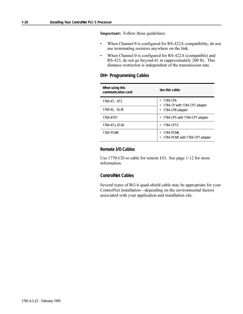
,PSRUWDQW)ROORZWKHVHJXLGHOLQHV
:KHQ&KDQQHOLVFRQILJXUHGIRU56$FRPSDWLELOLW\GRQRWXVHWHUPLQDWLQJUHVLVWRUVDQ\ZKHUHRQWKHOLQN
:KHQ&KDQQHOLVFRQILJXUHGIRU56$FRPSDWLEOHDQG56GRQRWJREH\RQGPDSSUR[LPDWHO\IW7KLVGLVWDQFHUHVWULFWLRQLVLQGHSHQGHQWRIWKHWUDQVPLVVLRQUDWH
DH+ Programming Cables
Remote I/O Cables
8VH&'RUFDEOHIRUUHPRWH,26HHSDJHIRUPRUHLQIRUPDWLRQ
ControlNet Cables
6HYHUDOW\SHVRI5*TXDGVKLHOGFDEOHPD\EHDSSURSULDWHIRU\RXU&RQWURO1HWLQVWDOODWLRQ²GHSHQGLQJRQWKHHQYLURQPHQWDOIDFWRUVDVVRFLDWHGZLWK\RXUDSSOLFDWLRQDQGLQVWDOODWLRQVLWH
When using this communication card:
Use this cable:
1784-KT, -KT2 • 1784-CP6• 1784-CP with 1784-CP7 adapter• 1784-CP8 adapter1784-KL, -KL/B
1784-KTK1 • 1784-CP5 with 1784-CP7 adapter
1784-KTx, KTxD • 1784-CP13
1784-PCMK • 1784-PCM6• 1784-PCM5 with 1784-CP7 adapter
1785-6.5.22 - February 1999
Installing Your ControlNet PLC-5 Processor 1-21
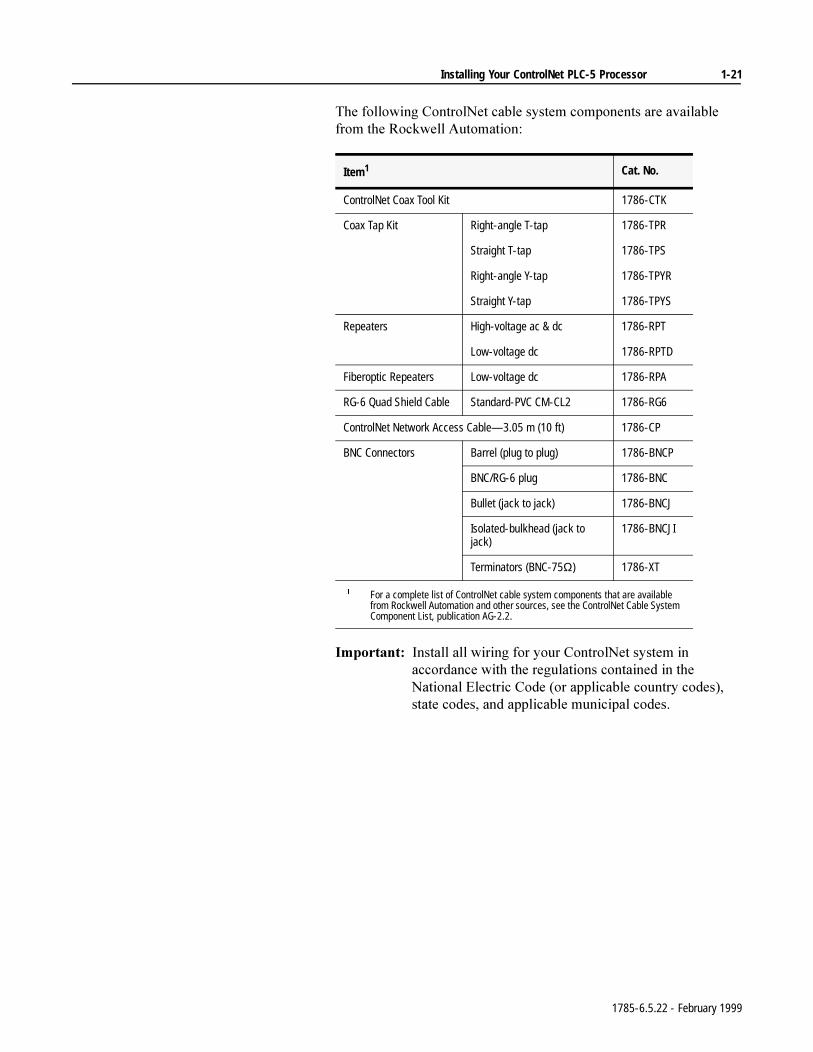
7KHIROORZLQJ&RQWURO1HWFDEOHV\VWHPFRPSRQHQWVDUHDYDLODEOHIURPWKH5RFNZHOO$XWRPDWLRQ
,PSRUWDQW,QVWDOODOOZLULQJIRU\RXU&RQWURO1HWV\VWHPLQDFFRUGDQFHZLWKWKHUHJXODWLRQVFRQWDLQHGLQWKH1DWLRQDO(OHFWULF&RGHRUDSSOLFDEOHFRXQWU\FRGHVVWDWHFRGHVDQGDSSOLFDEOHPXQLFLSDOFRGHV
Item1 Cat. No.
ControlNet Coax Tool Kit 1786-CTK
Coax Tap Kit Right-angle T-tap 1786-TPR
Straight T-tap 1786-TPS
Right-angle Y-tap 1786-TPYR
Straight Y-tap 1786-TPYS
Repeaters High-voltage ac & dc 1786-RPT
Low-voltage dc 1786-RPTD
Fiberoptic Repeaters Low-voltage dc 1786-RPA
RG-6 Quad Shield Cable Standard-PVC CM-CL2 1786-RG6
ControlNet Network Access Cable—3.05 m (10 ft) 1786-CP
BNC Connectors Barrel (plug to plug) 1786-BNCP
BNC/RG-6 plug 1786-BNC
Bullet (jack to jack) 1786-BNCJ
Isolated-bulkhead (jack to jack)
1786-BNCJI
Terminators (BNC-75Ω) 1786-XT
For a complete list of ControlNet cable system components that are available from Rockwell Automation and other sources, see the ControlNet Cable System Component List, publication AG-2.2.
1785-6.5.22 - February 1999

1-22 Installing Your ControlNet PLC-5 Processor
)RUGHWDLOHGLQIRUPDWLRQDERXW&RQWURO1HWFDEOLQJVHHWKHIROORZLQJSXEOLFDWLRQV
PublicationPublication
Number
ControlNet Cable System Component List AG-2.2
ControlNet Cable System Planning and Installation Manual 1786-6.2.1
ControlNet Coax Tap Installation Instructions 1786-2.3
ControlNet Network Access Cable Installation Instructions 1786-2.6
ControlNet Repeater Installation Instructions 1786-2.7
ControlNet System Overview 1786-2.9
Industrial Automation Wiring and Grounding Guidelines 1770-4.1
MORE
1785-6.5.22 - February 1999
Chapter 2
Planning to Use Your ControlNet PLC-5 Processor
Using This Chapter
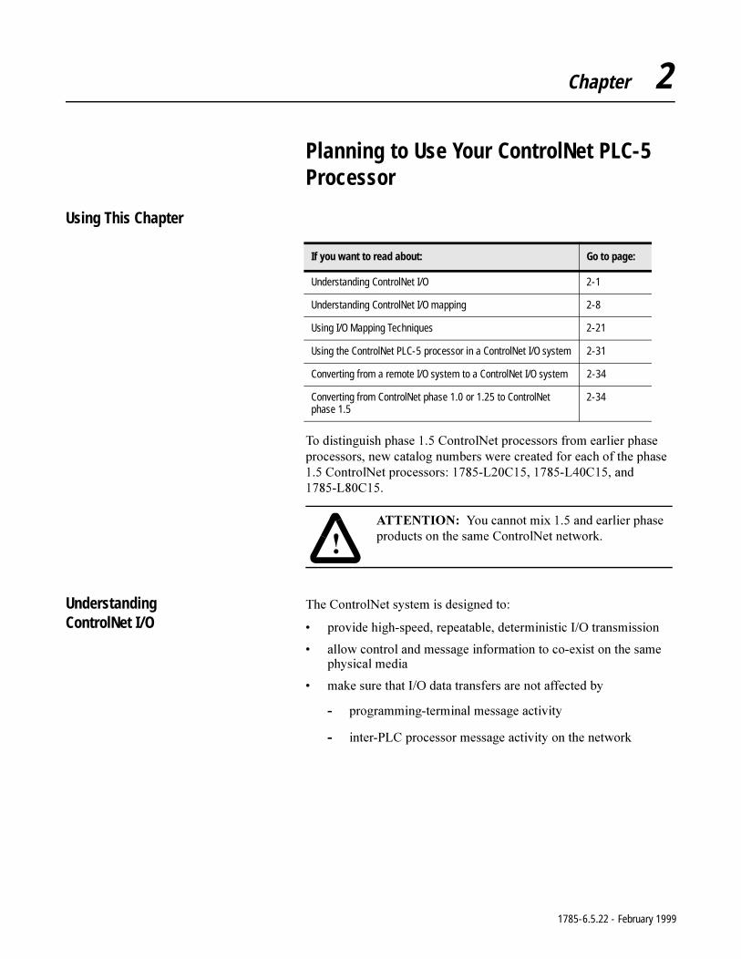
7RGLVWLQJXLVKSKDVH&RQWURO1HWSURFHVVRUVIURPHDUOLHUSKDVHSURFHVVRUVQHZFDWDORJQXPEHUVZHUHFUHDWHGIRUHDFKRIWKHSKDVH&RQWURO1HWSURFHVVRUV/&/&DQG/&
Understanding ControlNet I/O
7KH&RQWURO1HWV\VWHPLVGHVLJQHGWR
SURYLGHKLJKVSHHGUHSHDWDEOHGHWHUPLQLVWLF,2WUDQVPLVVLRQ
DOORZFRQWURODQGPHVVDJHLQIRUPDWLRQWRFRH[LVWRQWKHVDPHSK\VLFDOPHGLD
PDNHVXUHWKDW,2GDWDWUDQVIHUVDUHQRWDIIHFWHGE\
SURJUDPPLQJWHUPLQDOPHVVDJHDFWLYLW\
LQWHU3/&SURFHVVRUPHVVDJHDFWLYLW\RQWKHQHWZRUN
If you want to read about: Go to page:
Understanding ControlNet I/O 2-1
Understanding ControlNet I/O mapping 2-8
Using I/O Mapping Techniques 2-21
Using the ControlNet PLC-5 processor in a ControlNet I/O system 2-31
Converting from a remote I/O system to a ControlNet I/O system 2-34
Converting from ControlNet phase 1.0 or 1.25 to ControlNet phase 1.5
2-34
$77(17,21 <RXFDQQRWPL[DQGHDUOLHUSKDVHSURGXFWVRQWKHVDPH&RQWURO1HWQHWZRUN
1785-6.5.22 - February 1999
2-2 Planning to Use Your ControlNet PLC-5 Processor
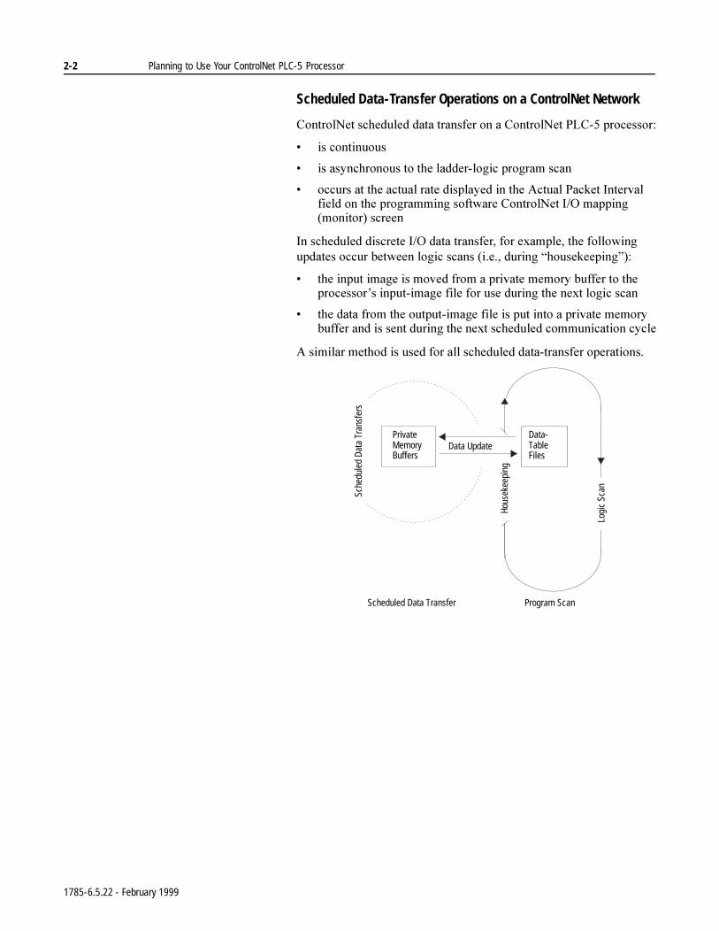
Scheduled Data-Transfer Operations on a ControlNet Network
&RQWURO1HWVFKHGXOHGGDWDWUDQVIHURQD&RQWURO1HW3/&SURFHVVRU
LVFRQWLQXRXV
LVDV\QFKURQRXVWRWKHODGGHUORJLFSURJUDPVFDQ
RFFXUVDWWKHDFWXDOUDWHGLVSOD\HGLQWKH$FWXDO3DFNHW,QWHUYDOILHOGRQWKHSURJUDPPLQJVRIWZDUH&RQWURO1HW,2PDSSLQJPRQLWRUVFUHHQ
,QVFKHGXOHGGLVFUHWH,2GDWDWUDQVIHUIRUH[DPSOHWKHIROORZLQJXSGDWHVRFFXUEHWZHHQORJLFVFDQVLHGXULQJ³KRXVHNHHSLQJ´
WKHLQSXWLPDJHLVPRYHGIURPDSULYDWHPHPRU\EXIIHUWRWKHSURFHVVRU¶VLQSXWLPDJHILOHIRUXVHGXULQJWKHQH[WORJLFVFDQ
WKHGDWDIURPWKHRXWSXWLPDJHILOHLVSXWLQWRDSULYDWHPHPRU\EXIIHUDQGLVVHQWGXULQJWKHQH[WVFKHGXOHGFRPPXQLFDWLRQF\FOH
$VLPLODUPHWKRGLVXVHGIRUDOOVFKHGXOHGGDWDWUDQVIHURSHUDWLRQV
Hous
ekee
ping
Program Scan
Data-TableFiles
Scheduled Data Transfer
PrivateMemoryBuffers
Sche
dule
d Da
ta T
rans
fers
Data Update
Logi
c Sc
an
1785-6.5.22 - February 1999
Planning to Use Your ControlNet PLC-5 Processor 2-3
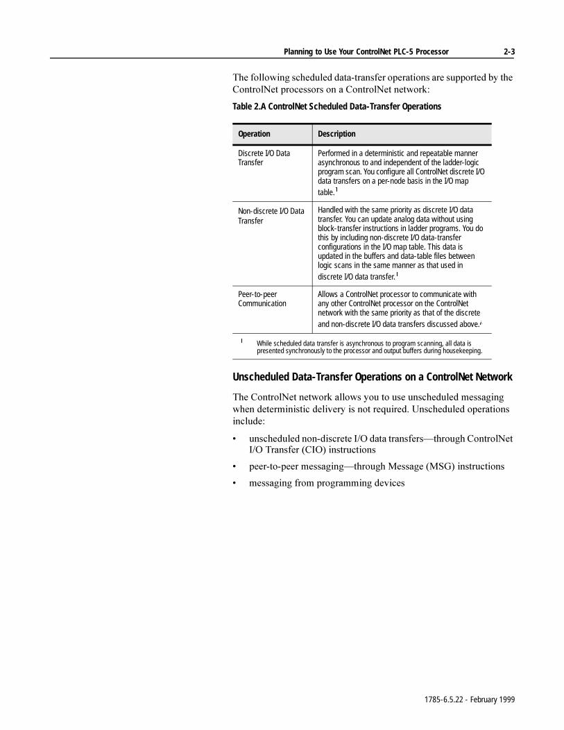
7KHIROORZLQJVFKHGXOHGGDWDWUDQVIHURSHUDWLRQVDUHVXSSRUWHGE\WKH&RQWURO1HWSURFHVVRUVRQD&RQWURO1HWQHWZRUN
Table 2.A ControlNet Scheduled Data-Transfer Operations
Unscheduled Data-Transfer Operations on a ControlNet Network
7KH&RQWURO1HWQHWZRUNDOORZV\RXWRXVHXQVFKHGXOHGPHVVDJLQJZKHQGHWHUPLQLVWLFGHOLYHU\LVQRWUHTXLUHG8QVFKHGXOHGRSHUDWLRQVLQFOXGH
XQVFKHGXOHGQRQGLVFUHWH,2GDWDWUDQVIHUV²WKURXJK&RQWURO1HW,27UDQVIHU&,2LQVWUXFWLRQV
SHHUWRSHHUPHVVDJLQJ²WKURXJK0HVVDJH06*LQVWUXFWLRQV
PHVVDJLQJIURPSURJUDPPLQJGHYLFHV
Operation Description
Discrete I/O Data Transfer
Performed in a deterministic and repeatable manner asynchronous to and independent of the ladder-logic program scan. You configure all ControlNet discrete I/O data transfers on a per-node basis in the I/O map table.
Non-discrete I/O Data Transfer
Handled with the same priority as discrete I/O data transfer. You can update analog data without using block-transfer instructions in ladder programs. You do this by including non-discrete I/O data-transfer configurations in the I/O map table. This data is updated in the buffers and data-table files between logic scans in the same manner as that used in discrete I/O data transfer.
Peer-to-peer Communication
Allows a ControlNet processor to communicate with any other ControlNet processor on the ControlNet network with the same priority as that of the discrete and non-discrete I/O data transfers discussed above.¢
While scheduled data transfer is asynchronous to program scanning, all data is
presented synchronously to the processor and output buffers during housekeeping.
1785-6.5.22 - February 1999
2-4 Planning to Use Your ControlNet PLC-5 Processor
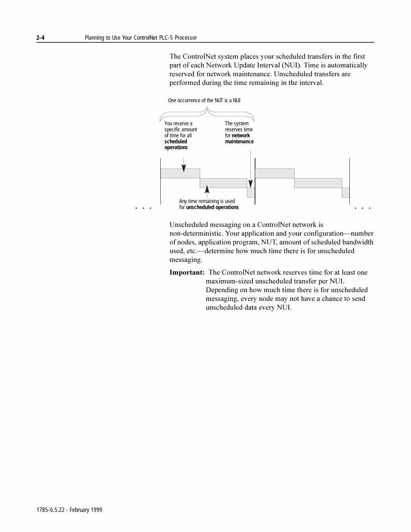
7KH&RQWURO1HWV\VWHPSODFHV\RXUVFKHGXOHGWUDQVIHUVLQWKHILUVWSDUWRIHDFK1HWZRUN8SGDWH,QWHUYDO18,7LPHLVDXWRPDWLFDOO\UHVHUYHGIRUQHWZRUNPDLQWHQDQFH8QVFKHGXOHGWUDQVIHUVDUHSHUIRUPHGGXULQJWKHWLPHUHPDLQLQJLQWKHLQWHUYDO
8QVFKHGXOHGPHVVDJLQJRQD&RQWURO1HWQHWZRUNLVQRQGHWHUPLQLVWLF<RXUDSSOLFDWLRQDQG\RXUFRQILJXUDWLRQ²QXPEHURIQRGHVDSSOLFDWLRQSURJUDP187DPRXQWRIVFKHGXOHGEDQGZLGWKXVHGHWF²GHWHUPLQHKRZPXFKWLPHWKHUHLVIRUXQVFKHGXOHGPHVVDJLQJ
,PSRUWDQW7KH&RQWURO1HWQHWZRUNUHVHUYHVWLPHIRUDWOHDVWRQHPD[LPXPVL]HGXQVFKHGXOHGWUDQVIHUSHU18,'HSHQGLQJRQKRZPXFKWLPHWKHUHLVIRUXQVFKHGXOHGPHVVDJLQJHYHU\QRGHPD\QRWKDYHDFKDQFHWRVHQGXQVFKHGXOHGGDWDHYHU\18,
You reserve a specific amount of time for all scheduled operations
Any time remaining is used for unscheduled operations
The system reserves time for network maintenance
One occurrence of the NUT is a NUI
. . .. . .
1785-6.5.22 - February 1999
Planning to Use Your ControlNet PLC-5 Processor 2-5
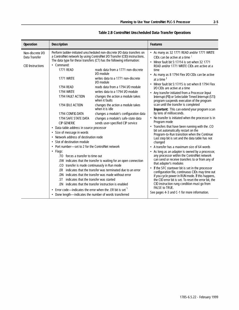
Table 2.B ControlNet Unscheduled Data-Transfer Operations
Operation Description Features
Non-discrete I/O Data Transfer
CIO Instructions
Perform ladder-initiated unscheduled non-discrete I/O data transfers on a ControlNet network by using ControlNet I/O Transfer (CIO) instructions. The data type for these transfers (CT) has the following information:• Command:
1771 READ reads data from a 1771 non-discrete I/O module
1771 WRITE writes data to a 1771 non-discrete I/O module
1794 READ reads data from a 1794 I/O module1794 WRITE writes data to a 1794 I/O module1794 FAULT ACTION changes the action a module takes
when it faults1794 IDLE ACTION changes the action a module takes
when it is idle1794 CONFIG DATA changes a module’s configuration data1794 SAFE STATE DATA changes a module’s safe-state data CIP GENERIC sends user-specified CIP service
• Data-table address in source processor• Size of message in words• Network address of destination node• Slot of destination module• Port number—set to 2 for the ControlNet network• Flags:
.TO forces a transfer to time out
.EW indicates that the transfer is waiting for an open connection
.CO transfer is made continuously in Run mode
.ER indicates that the transfer was terminated due to an error
.DN indicates that the transfer was made without error
.ST indicates that the transfer was started
.EN indicates that the transfer instruction is enabled
• Error code—indicates the error when the .ER bit is set
• Done length—indicates the number of words transferred
• As many as 32 1771 READ and/or 1771 WRITE CIOs can be active at a time
• Minor fault bit S:17/14 is set when 32 1771 READ and/or 1771 WRITE CIOs are active at a time
• As many as 8 1794 Flex I/O CIOs can be active at a time
• Minor fault bit S:17/15 is set when 8 1794 Flex I/O CIOs are active at a time
• Any transfer initiated from a Processor Input Interrupt (PII) or Selectable Timed Interrupt (STI) program suspends execution of the program scan until the transfer is completedImportant: This can extend your program scan by tens of milliseconds.
• No transfer is initiated when the processor is in Program mode
• Transfers that have been running with the .CO bit set automatically restart on the Program-to-Run transition when the Continue Last step bit is set and the data table has not changed
• A transfer has a maximum size of 64 words• As long as an adapter is owned by a processor,
any processor within the ControlNet network can send or receive transfers to or from any of that adapter’s modules
• If the SFC startover bit is set in the processor configuration file, continuous CIOs may time out if you cycle power in RUN mode. If this happens, the CIO error bit is set. To reset the error bit, the CIO instruction rung condition must go from FALSE to TRUE.
See pages 4-3 and C-1 for more information.
1785-6.5.22 - February 1999
2-6 Planning to Use Your ControlNet PLC-5 Processor
Using I/O Forcing Operations
&RQWURO1HW,2IRUFLQJRFFXUVLQWKHVDPHZD\DVUHPRWH,2IRUFLQJLQWKH&RQWURO1HWSURFHVVRUV7KHSURFHVVRUSHUIRUPVWKHIRUFLQJDQGWUDQVPLWVWKHIRUFHGGDWDWRWKHRXWSXWDQGLQSXWLPDJHWDEOHV<RXFDQIRUFHDQ\GLVFUHWH,2GDWDSODFHGLQWKH,2LPDJHKRZHYHUIRUFLQJRIQRQGLVFUHWH,2GDWDLVQRWVXSSRUWHG
)RUGHWDLOHGLQIRUPDWLRQDERXWIRUFLQJVHH\RXUSURJUDPPLQJVRIWZDUHGRFXPHQWDWLRQ
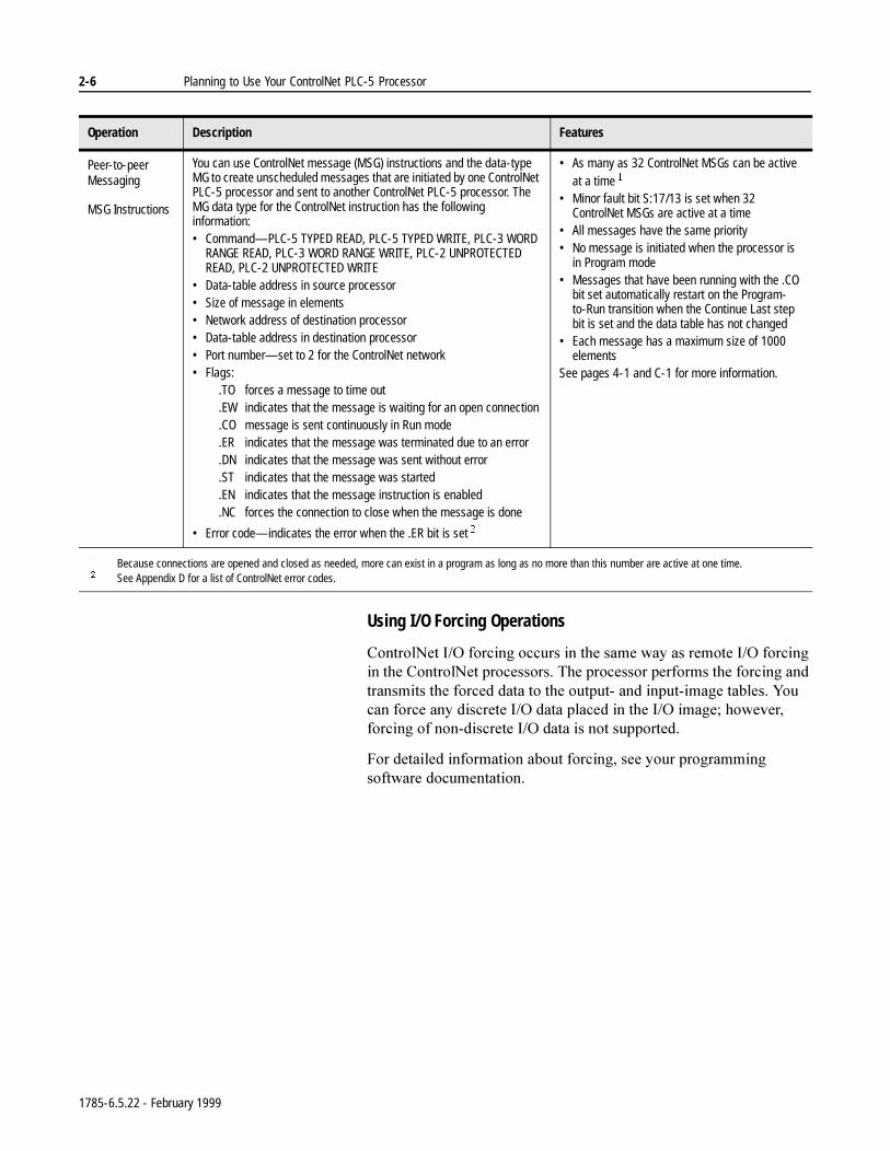
Peer-to-peer Messaging
MSG Instructions
You can use ControlNet message (MSG) instructions and the data-type MG to create unscheduled messages that are initiated by one ControlNet PLC-5 processor and sent to another ControlNet PLC-5 processor. The MG data type for the ControlNet instruction has the following information:• Command—PLC-5 TYPED READ, PLC-5 TYPED WRITE, PLC-3 WORD
RANGE READ, PLC-3 WORD RANGE WRITE, PLC-2 UNPROTECTED READ, PLC-2 UNPROTECTED WRITE
• Data-table address in source processor• Size of message in elements• Network address of destination processor• Data-table address in destination processor• Port number—set to 2 for the ControlNet network• Flags:
.TO forces a message to time out
.EW indicates that the message is waiting for an open connection
.CO message is sent continuously in Run mode
.ER indicates that the message was terminated due to an error
.DN indicates that the message was sent without error
.ST indicates that the message was started
.EN indicates that the message instruction is enabled
.NC forces the connection to close when the message is done
• Error code—indicates the error when the .ER bit is set
• As many as 32 ControlNet MSGs can be active at a time
• Minor fault bit S:17/13 is set when 32 ControlNet MSGs are active at a time
• All messages have the same priority• No message is initiated when the processor is
in Program mode• Messages that have been running with the .CO
bit set automatically restart on the Program- to-Run transition when the Continue Last step bit is set and the data table has not changed
• Each message has a maximum size of 1000 elements
See pages 4-1 and C-1 for more information.
Because connections are opened and closed as needed, more can exist in a program as long as no more than this number are active at one time. See Appendix D for a list of ControlNet error codes.
Operation Description Features
1785-6.5.22 - February 1999
Planning to Use Your ControlNet PLC-5 Processor 2-7
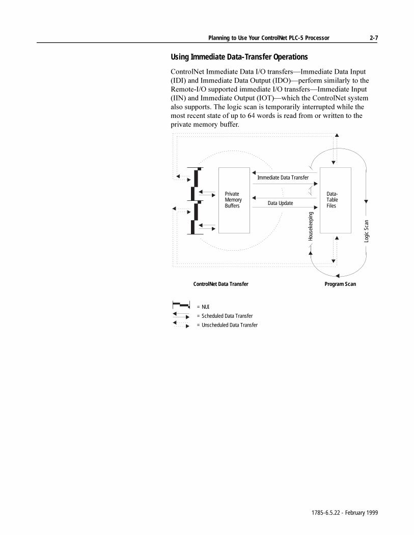
Using Immediate Data-Transfer Operations
&RQWURO1HW,PPHGLDWH'DWD,2WUDQVIHUV²,PPHGLDWH'DWD,QSXW,',DQG,PPHGLDWH'DWD2XWSXW,'2²SHUIRUPVLPLODUO\WRWKH5HPRWH,2VXSSRUWHGLPPHGLDWH,2WUDQVIHUV²,PPHGLDWH,QSXW,,1DQG,PPHGLDWH2XWSXW,27²ZKLFKWKH&RQWURO1HWV\VWHPDOVRVXSSRUWV7KHORJLFVFDQLVWHPSRUDULO\LQWHUUXSWHGZKLOHWKHPRVWUHFHQWVWDWHRIXSWRZRUGVLVUHDGIURPRUZULWWHQWRWKHSULYDWHPHPRU\EXIIHU
ControlNet Data Transfer
PrivateMemoryBuffers
Hous
ekee
ping
Logi
c Sc
an
Program Scan
Data-TableFiles
Immediate Data Transfer
= Unscheduled Data Transfer
= Scheduled Data Transfer
= NUI
Data Update
1785-6.5.22 - February 1999
2-8 Planning to Use Your ControlNet PLC-5 Processor
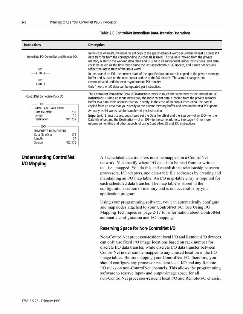
Table 2.C ControlNet Immediate Data-Transfer Operations
Understanding ControlNet I/O Mapping
$OOVFKHGXOHGGDWDWUDQVIHUVPXVWEHPDSSHGRQD&RQWURO1HWQHWZRUN<RXVSHFLI\ZKHUH,2GDWDLVWREHUHDGIURPRUZULWWHQWR²LHPDSSHG<RXGRWKLVDQGHVWDEOLVKWKHUHODWLRQVKLSEHWZHHQSURFHVVRUV,2DGDSWHUVDQGGDWDWDEOHILOHDGGUHVVHVE\FUHDWLQJDQGPDLQWDLQLQJDQ,2PDSWDEOH$Q,2PDSWDEOHHQWU\LVUHTXLUHGIRUHDFKVFKHGXOHGGDWDWUDQVIHU7KHPDSWDEOHLVVWRUHGLQWKHFRQILJXUDWLRQVHFWLRQRIPHPRU\DQGLVQRWDFFHVVLEOHE\\RXUDSSOLFDWLRQSURJUDP
8VLQJ\RXUSURJUDPPLQJVRIWZDUH\RXFDQDXWRPDWLFDOO\FRQILJXUHDQGPDSQRGHVDWWDFKHGWR\RXU&RQWURO1HW,26HH8VLQJ,20DSSLQJ7HFKQLTXHVRQSDJHIRULQIRUPDWLRQDERXW&RQWURO1HWDXWRPDWLFFRQILJXUDWLRQDQG,2PDSSLQJ
Reserving Space for Non-ControlNet I/O
1RQ&RQWURO1HWSURFHVVRUUHVLGHQWORFDO,2DQG5HPRWH,2GHYLFHVFDQRQO\XVHIL[HG,2LPDJHORFDWLRQVEDVHGRQUDFNQXPEHUIRUGLVFUHWH,2GDWDWUDQVIHUZKLOHGLVFUHWH,2GDWDWUDQVIHUEHWZHHQ&RQWURO1HWQRGHVFDQEHPDSSHGWRDQ\XQXVHGORFDWLRQLQWKH,2LPDJHWDEOHV%HIRUHPDSSLQJ\RXU&RQWURO1HW,2WKHUHIRUH\RXVKRXOGFRQILJXUHDQ\SURFHVVRUUHVLGHQWORFDO,2DQGDQ\5HPRWH,2UDFNVRQQRQ&RQWURO1HWFKDQQHOV7KLVDOORZVWKHSURJUDPPLQJVRIWZDUHWRUHVHUYHLQSXWDQGRXWSXWLPDJHVSDFHIRUDOOQRQ&RQWURO1HWSURFHVVRUUHVLGHQWORFDO,2DQG5HPRWH,2FKDVVLV
Instructions Description
In the case of an IIN, the most recent copy of the specified input word secured in the last discrete I/O data transfer from the corresponding I/O chassis is used. This value is moved from the private memory buffer to the working data table and is used in all subsequent ladder instructions. This data could be as old as the time taken since the last asynchronous I/O update, and it may not actually reflect the latest state of the input word. In the case of an IOT, the current state of the specified output word is copied to the private memory buffer and is used on the next output update to the I/O chassis. The actual change is not communicated until the next asynchronous I/O transfer.Only 1 word of I/O data can be updated per instruction.
The ControlNet Immediate Data I/O instructions work in much the same way as the immediate I/O instructions. During an input instruction, the most recent data is copied from the private memory buffer to a data-table address that you specify. In the case of an output instruction, the data is copied from an area that you specify to the private memory buffer and sent on the next I/O update. As many as 64 words can be transferred per instruction.Important: In most cases, you should set the Data file offset and the Source—of an IDO—or the Data file offset and the Destination—of an IDI—to the same address. See page 4-5 for more information on this and other aspects of using ControlNet IDI and IDO instructions.
Immediate I/O-ControlNet and Remote I/O
001( )IIN
001( )IOT
ControlNet Immediate Data I/O
IDIIMMEDIATE DATA INPUTData file offsetLength
23210
Destination N11:232
IDOIMMEDIATE DATA OUTPUTData file offsetLength
17524
Source N12:175
1785-6.5.22 - February 1999
Planning to Use Your ControlNet PLC-5 Processor 2-9
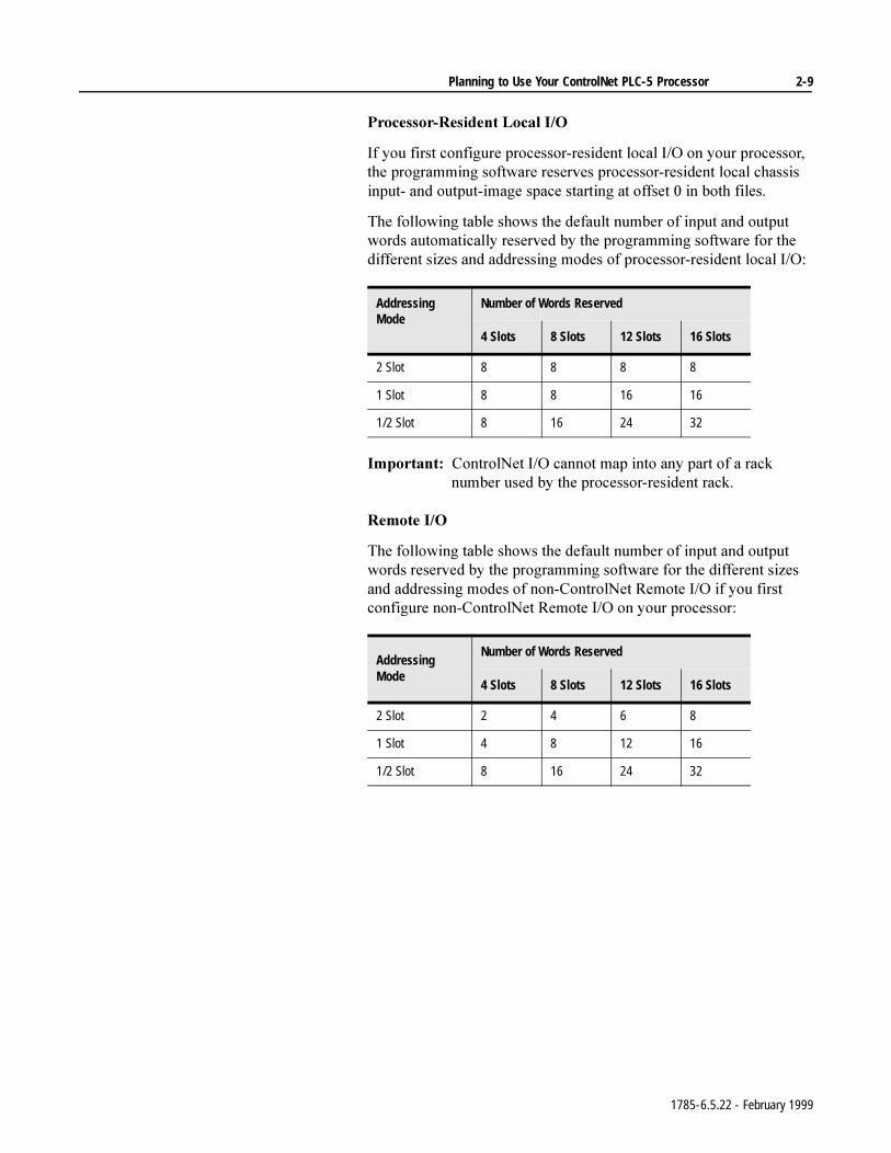
3URFHVVRU5HVLGHQW/RFDO,2
,I\RXILUVWFRQILJXUHSURFHVVRUUHVLGHQWORFDO,2RQ\RXUSURFHVVRUWKHSURJUDPPLQJVRIWZDUHUHVHUYHVSURFHVVRUUHVLGHQWORFDOFKDVVLVLQSXWDQGRXWSXWLPDJHVSDFHVWDUWLQJDWRIIVHWLQERWKILOHV
7KHIROORZLQJWDEOHVKRZVWKHGHIDXOWQXPEHURILQSXWDQGRXWSXWZRUGVDXWRPDWLFDOO\UHVHUYHGE\WKHSURJUDPPLQJVRIWZDUHIRUWKHGLIIHUHQWVL]HVDQGDGGUHVVLQJPRGHVRISURFHVVRUUHVLGHQWORFDO,2
,PSRUWDQW&RQWURO1HW,2FDQQRWPDSLQWRDQ\SDUWRIDUDFNQXPEHUXVHGE\WKHSURFHVVRUUHVLGHQWUDFN
5HPRWH,2
7KHIROORZLQJWDEOHVKRZVWKHGHIDXOWQXPEHURILQSXWDQGRXWSXWZRUGVUHVHUYHGE\WKHSURJUDPPLQJVRIWZDUHIRUWKHGLIIHUHQWVL]HVDQGDGGUHVVLQJPRGHVRIQRQ&RQWURO1HW5HPRWH,2LI\RXILUVWFRQILJXUHQRQ&RQWURO1HW5HPRWH,2RQ\RXUSURFHVVRU
AddressingMode
Number of Words Reserved
4 Slots 8 Slots 12 Slots 16 Slots
2 Slot 8 8 8 8
1 Slot 8 8 16 16
1/2 Slot 8 16 24 32
Addressing Mode
Number of Words Reserved
4 Slots 8 Slots 12 Slots 16 Slots
2 Slot 2 4 6 8
1 Slot 4 8 12 16
1/2 Slot 8 16 24 32
1785-6.5.22 - February 1999
2-10 Planning to Use Your ControlNet PLC-5 Processor
7KHSURJUDPPLQJVRIWZDUHUHVHUYHVQRQ&RQWURO1HW5HPRWH,2RXWSXWDQGLQSXWLPDJHVSDFHDFFRUGLQJWRWKHVHJXLGHOLQHV
,WGRHVQRWRYHUODSSURFHVVRUUHVLGHQWORFDO,2UHVHUYHGLPDJHVSDFH
,WDGGUHVVHVLQSXWDQGRXWSXWLPDJHVSDFHRIIVHWLQRFWDOIURP
± ²IRUWKH3/&&SURFHVVRU
± ²IRUWKH3/&&SURFHVVRU
± ²IRUWKH3/&&SURFHVVRU
7KHRXWSXWLPDJHRIIVHWYDOXHLQWKH,2PDSFRUUHVSRQGVWRWKHILUVWVORWRIWKHUHIHUHQFHGFKDVVLV²LHLQDVORWFKDVVLVVHWIRUVORWDGGUHVVLQJWKHFRUUHVSRQGLQJRXWSXWLPDJHRIIVHWRI2ZRXOGPDSWKHZRUGV222DQG2WRVORWVDQGUHVSHFWLYHO\
7KHLQSXWLPDJHRIIVHWFRUUHVSRQGVWRWKHILUVWVORWLQWKHUHIHUHQFHGUDFNDQGWKHRIIVHWORFDWLRQRIWKHLQSXWPRGXOHVLQWKDWUDFNFRUUHVSRQGVWRWKHVDPHRIIVHWLQWKHLPDJHWDEOH²LHLIDFKDVVLVVHWIRUVORWDGGUHVVLQJKDVDQLQSXWLPDJHRIIVHWRI,DQGDQLQSXWPRGXOHLQVORWWKHZRUGWKDWFRUUHVSRQGVWRWKDWLQSXWPRGXOHZRXOGEH,RU,
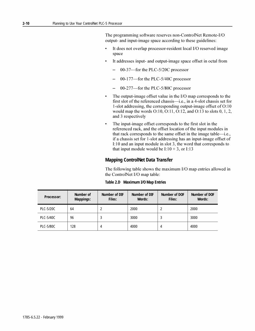
Mapping ControlNet Data Transfer
7KHIROORZLQJWDEOHVKRZVWKHPD[LPXP,2PDSHQWULHVDOORZHGLQWKH&RQWURO1HW,2PDSWDEOH
Table 2.D Maximum I/O Map Entries
Processor:Number of Mappings:
Number of DIF Files:
Number of DIF Words:
Number of DOF Files:
Number of DOF Words:
PLC-5/20C 64 2 2000 2 2000
PLC-5/40C 96 3 3000 3 3000
PLC-5/80C 128 4 4000 4 4000
1785-6.5.22 - February 1999
Planning to Use Your ControlNet PLC-5 Processor 2-11
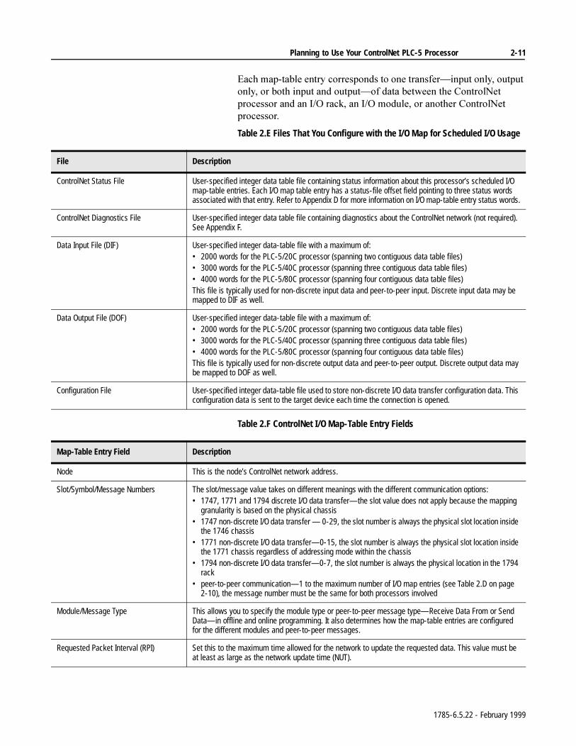
(DFKPDSWDEOHHQWU\FRUUHVSRQGVWRRQHWUDQVIHU²LQSXWRQO\RXWSXWRQO\RUERWKLQSXWDQGRXWSXW²RIGDWDEHWZHHQWKH&RQWURO1HWSURFHVVRUDQGDQ,2UDFNDQ,2PRGXOHRUDQRWKHU&RQWURO1HWSURFHVVRU
Table 2.E Files That You Configure with the I/O Map for Scheduled I/O Usage
Table 2.F ControlNet I/O Map-Table Entry Fields
File Description
ControlNet Status File User-specified integer data table file containing status information about this processor’s scheduled I/O map-table entries. Each I/O map table entry has a status-file offset field pointing to three status words associated with that entry. Refer to Appendix D for more information on I/O map-table entry status words.
ControlNet Diagnostics File User-specified integer data table file containing diagnostics about the ControlNet network (not required). See Appendix F.
Data Input File (DIF) User-specified integer data-table file with a maximum of:• 2000 words for the PLC-5/20C processor (spanning two contiguous data table files)• 3000 words for the PLC-5/40C processor (spanning three contiguous data table files)• 4000 words for the PLC-5/80C processor (spanning four contiguous data table files)This file is typically used for non-discrete input data and peer-to-peer input. Discrete input data may be mapped to DIF as well.
Data Output File (DOF) User-specified integer data-table file with a maximum of:• 2000 words for the PLC-5/20C processor (spanning two contiguous data table files)• 3000 words for the PLC-5/40C processor (spanning three contiguous data table files)• 4000 words for the PLC-5/80C processor (spanning four contiguous data table files)This file is typically used for non-discrete output data and peer-to-peer output. Discrete output data may be mapped to DOF as well.
Configuration File User-specified integer data-table file used to store non-discrete I/O data transfer configuration data. This configuration data is sent to the target device each time the connection is opened.
Map-Table Entry Field Description
Node This is the node’s ControlNet network address.
Slot/Symbol/Message Numbers The slot/message value takes on different meanings with the different communication options:• 1747, 1771 and 1794 discrete I/O data transfer—the slot value does not apply because the mapping
granularity is based on the physical chassis• 1747 non-discrete I/O data transfer — 0-29, the slot number is always the physical slot location inside
the 1746 chassis• 1771 non-discrete I/O data transfer—0-15, the slot number is always the physical slot location inside
the 1771 chassis regardless of addressing mode within the chassis• 1794 non-discrete I/O data transfer—0-7, the slot number is always the physical location in the 1794
rack• peer-to-peer communication—1 to the maximum number of I/O map entries (see Table 2.D on page
2-10), the message number must be the same for both processors involved
Module/Message Type This allows you to specify the module type or peer-to-peer message type—Receive Data From or Send Data—in offline and online programming. It also determines how the map-table entries are configured for the different modules and peer-to-peer messages.
Requested Packet Interval (RPI) Set this to the maximum time allowed for the network to update the requested data. This value must be at least as large as the network update time (NUT).
1785-6.5.22 - February 1999
2-12 Planning to Use Your ControlNet PLC-5 Processor
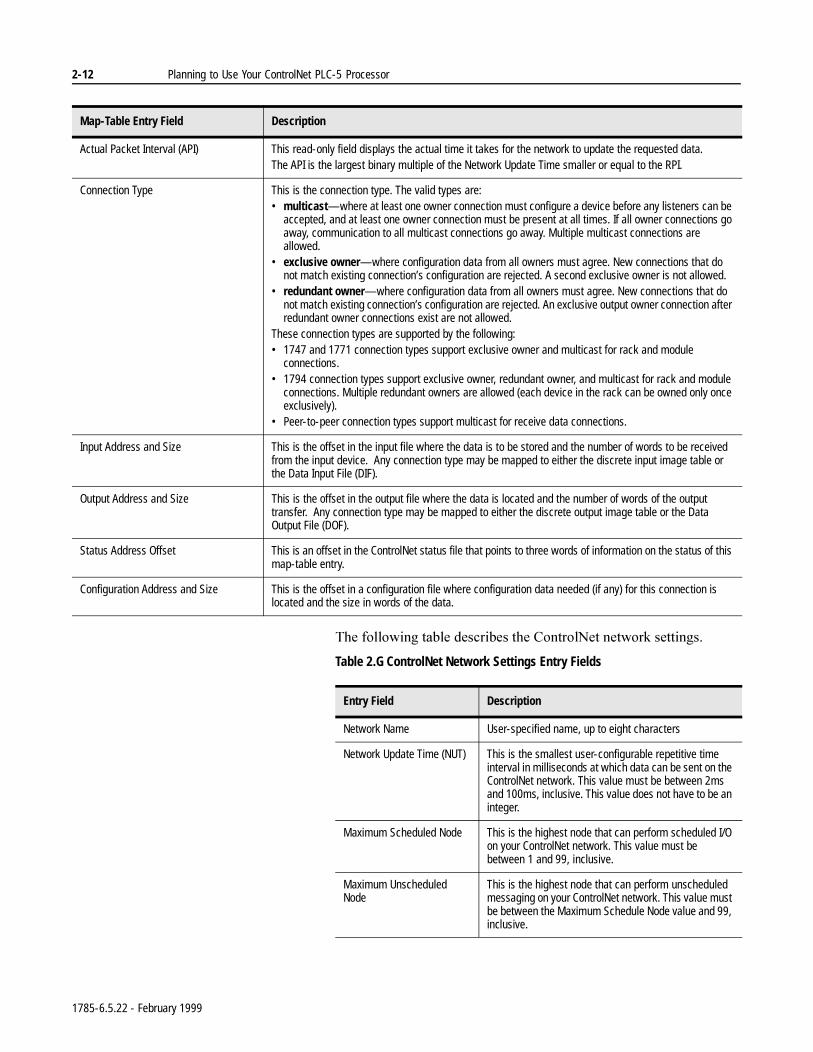
7KHIROORZLQJWDEOHGHVFULEHVWKH&RQWURO1HWQHWZRUNVHWWLQJV
Table 2.G ControlNet Network Settings Entry Fields
Actual Packet Interval (API) This read-only field displays the actual time it takes for the network to update the requested data.The API is the largest binary multiple of the Network Update Time smaller or equal to the RPI.
Connection Type This is the connection type. The valid types are:• multicast—where at least one owner connection must configure a device before any listeners can be
accepted, and at least one owner connection must be present at all times. If all owner connections go away, communication to all multicast connections go away. Multiple multicast connections are allowed.
• exclusive owner—where configuration data from all owners must agree. New connections that do not match existing connection’s configuration are rejected. A second exclusive owner is not allowed.
• redundant owner—where configuration data from all owners must agree. New connections that do not match existing connection’s configuration are rejected. An exclusive output owner connection after redundant owner connections exist are not allowed.
These connection types are supported by the following:• 1747 and 1771 connection types support exclusive owner and multicast for rack and module
connections.• 1794 connection types support exclusive owner, redundant owner, and multicast for rack and module
connections. Multiple redundant owners are allowed (each device in the rack can be owned only once exclusively).
• Peer-to-peer connection types support multicast for receive data connections.
Input Address and Size This is the offset in the input file where the data is to be stored and the number of words to be received from the input device. Any connection type may be mapped to either the discrete input image table or the Data Input File (DIF).
Output Address and Size This is the offset in the output file where the data is located and the number of words of the output transfer. Any connection type may be mapped to either the discrete output image table or the Data Output File (DOF).
Status Address Offset This is an offset in the ControlNet status file that points to three words of information on the status of this map-table entry.
Configuration Address and Size This is the offset in a configuration file where configuration data needed (if any) for this connection is located and the size in words of the data.
Map-Table Entry Field Description
Entry Field Description
Network Name User-specified name, up to eight characters
Network Update Time (NUT) This is the smallest user-configurable repetitive time interval in milliseconds at which data can be sent on the ControlNet network. This value must be between 2ms and 100ms, inclusive. This value does not have to be an integer.
Maximum Scheduled Node This is the highest node that can perform scheduled I/O on your ControlNet network. This value must be between 1 and 99, inclusive.
Maximum Unscheduled Node
This is the highest node that can perform unscheduled messaging on your ControlNet network. This value must be between the Maximum Schedule Node value and 99, inclusive.
1785-6.5.22 - February 1999
Planning to Use Your ControlNet PLC-5 Processor 2-13
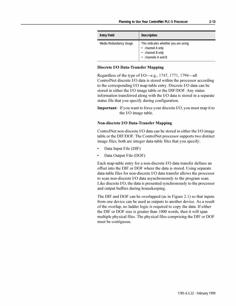
'LVFUHWH,2'DWD7UDQVIHU0DSSLQJ
5HJDUGOHVVRIWKHW\SHRI,2²HJ²DOO&RQWURO1HWGLVFUHWH,2GDWDLVVWRUHGZLWKLQWKHSURFHVVRUDFFRUGLQJWRWKHFRUUHVSRQGLQJ,2PDSWDEOHHQWU\'LVFUHWH,2GDWDFDQEHVWRUHGLQHLWKHUWKH,2LPDJHWDEOHRUWKH',)'2)$Q\VWDWXVLQIRUPDWLRQWUDQVIHUUHGDORQJZLWKWKH,2GDWDLVVWRUHGLQDVHSDUDWHVWDWXVILOHWKDW\RXVSHFLI\GXULQJFRQILJXUDWLRQ
,PSRUWDQW,I\RXZDQWWRIRUFH\RXUGLVFUHWH,2\RXPXVWPDSLWWRWKH,2LPDJHWDEOH
1RQGLVFUHWH,2'DWD7UDQVIHU0DSSLQJ
&RQWURO1HWQRQGLVFUHWH,2GDWDFDQEHVWRUHGLQHLWKHUWKH,2LPDJHWDEOHRUWKH',)'2)7KH&RQWURO1HWSURFHVVRUVXSSRUWVWZRGLVWLQFWLPDJHILOHVERWKDUHLQWHJHUGDWDWDEOHILOHVWKDW\RXVSHFLI\
'DWD,QSXW)LOH',)
'DWD2XWSXW)LOH'2)
(DFKPDSWDEOHHQWU\IRUDQRQGLVFUHWH,2GDWDWUDQVIHUGHILQHVDQRIIVHWLQWRWKH',)RU'2)ZKHUHWKHGDWDLVVWRUHG8VLQJVHSDUDWHGDWDWDEOHILOHVIRUQRQGLVFUHWH,2GDWDWUDQVIHUDOORZVWKHSURFHVVRUWRVFDQQRQGLVFUHWH,2GDWDDV\QFKURQRXVO\WRWKHSURJUDPVFDQ/LNHGLVFUHWH,2WKHGDWDLVSUHVHQWHGV\QFKURQRXVO\WRWKHSURFHVVRUDQGRXWSXWEXIIHUVGXULQJKRXVHNHHSLQJ
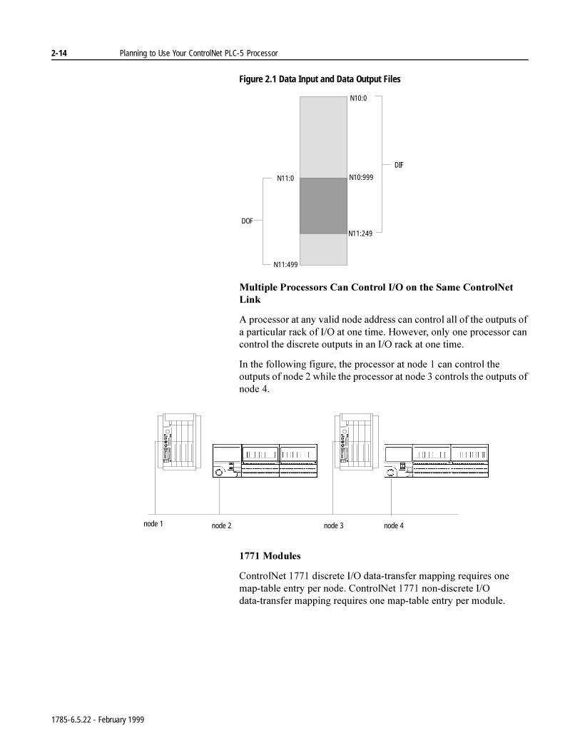
7KH',)DQG'2)FDQEHRYHUODSSHGDVLQ)LJXUHVRWKDWLQSXWVIURPRQHGHYLFHFDQEHXVHGDVRXWSXWVWRDQRWKHUGHYLFH$VDUHVXOWRIWKHRYHUODSQRODGGHUORJLFLVUHTXLUHGWRFRS\WKHGDWD,IHLWKHUWKH',)RU'2)VL]HLVJUHDWHUWKDQZRUGVWKHQLWZLOOVSDQPXOWLSOHSK\VLFDOILOHV7KHSK\VLFDOILOHVFRPSULVLQJWKH',)RU'2)PXVWEHFRQWLJXRXV
Media Redundancy Usage This indicates whether you are using:• channel A only• channel B only• channels A and B
Entry Field Description
1785-6.5.22 - February 1999
2-14 Planning to Use Your ControlNet PLC-5 Processor
Figure 2.1 Data Input and Data Output Files
0XOWLSOH3URFHVVRUV&DQ&RQWURO,2RQWKH6DPH&RQWURO1HW/LQN
$SURFHVVRUDWDQ\YDOLGQRGHDGGUHVVFDQFRQWURODOORIWKHRXWSXWVRIDSDUWLFXODUUDFNRI,2DWRQHWLPH+RZHYHURQO\RQHSURFHVVRUFDQFRQWUROWKHGLVFUHWHRXWSXWVLQDQ,2UDFNDWRQHWLPH
,QWKHIROORZLQJILJXUHWKHSURFHVVRUDWQRGHFDQFRQWUROWKHRXWSXWVRIQRGHZKLOHWKHSURFHVVRUDWQRGHFRQWUROVWKHRXWSXWVRIQRGH
0RGXOHV
&RQWURO1HWGLVFUHWH,2GDWDWUDQVIHUPDSSLQJUHTXLUHVRQHPDSWDEOHHQWU\SHUQRGH&RQWURO1HWQRQGLVFUHWH,2GDWDWUDQVIHUPDSSLQJUHTXLUHVRQHPDSWDEOHHQWU\SHUPRGXOH
N10:0
N10:999
DIF
DOF
N11:249
N11:0
N11:499
node 1 node 2 node 3 node 4
1785-6.5.22 - February 1999
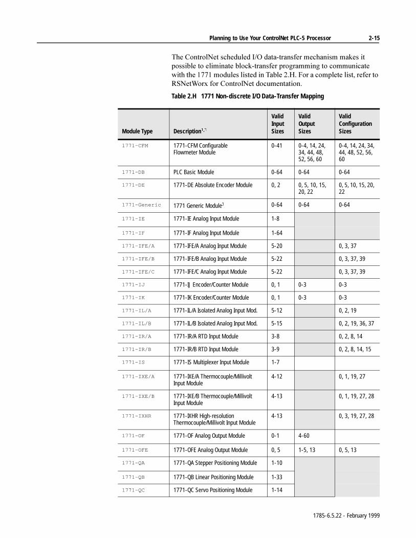
Planning to Use Your ControlNet PLC-5 Processor 2-15
7KH&RQWURO1HWVFKHGXOHG,2GDWDWUDQVIHUPHFKDQLVPPDNHVLWSRVVLEOHWRHOLPLQDWHEORFNWUDQVIHUSURJUDPPLQJWRFRPPXQLFDWHZLWKWKHPRGXOHVOLVWHGLQ7DEOH+)RUDFRPSOHWHOLVWUHIHUWR561HW:RU[IRU&RQWURO1HWGRFXPHQWDWLRQ
Table 2.H 1771 Non-discrete I/O Data-Transfer Mapping
Module Type Description
Valid InputSizes
Valid OutputSizes
Valid ConfigurationSizes
1771-CFM 1771-CFM Configurable Flowmeter Module
0-41 0-4, 14, 24, 34, 44, 48, 52, 56, 60
0-4, 14, 24, 34, 44, 48, 52, 56, 60
1771-DB PLC Basic Module 0-64 0-64 0-64
1771-DE 1771-DE Absolute Encoder Module 0, 2 0, 5, 10, 15, 20, 22
0, 5, 10, 15, 20, 22
1771-Generic 1771 Generic Module 0-64 0-64 0-64
1771-IE 1771-IE Analog Input Module 1-8
1771-IF 1771-IF Analog Input Module 1-64
1771-IFE/A 1771-IFE/A Analog Input Module 5-20 0, 3, 37
1771-IFE/B 1771-IFE/B Analog Input Module 5-22 0, 3, 37, 39
1771-IFE/C 1771-IFE/C Analog Input Module 5-22 0, 3, 37, 39
1771-IJ 1771-IJ Encoder/Counter Module 0, 1 0-3 0-3
1771-IK 1771-IK Encoder/Counter Module 0, 1 0-3 0-3
1771-IL/A 1771-IL/A Isolated Analog Input Mod. 5-12 0, 2, 19
1771-IL/B 1771-IL/B Isolated Analog Input Mod. 5-15 0, 2, 19, 36, 37
1771-IR/A 1771-IR/A RTD Input Module 3-8 0, 2, 8, 14
1771-IR/B 1771-IR/B RTD Input Module 3-9 0, 2, 8, 14, 15
1771-IS 1771-IS Multiplexer Input Module 1-7
1771-IXE/A 1771-IXE/A Thermocouple/Millivolt Input Module
4-12 0, 1, 19, 27
1771-IXE/B 1771-IXE/B Thermocouple/Millivolt Input Module
4-13 0, 1, 19, 27, 28
1771-IXHR 1771-IXHR High-resolution Thermocouple/Millivolt Input Module
4-13 0, 3, 19, 27, 28
1771-OF 1771-OF Analog Output Module 0-1 4-60
1771-OFE 1771-OFE Analog Output Module 0, 5 1-5, 13 0, 5, 13
1771-QA 1771-QA Stepper Positioning Module 1-10
1771-QB 1771-QB Linear Positioning Module 1-33
1771-QC 1771-QC Servo Positioning Module 1-14
1785-6.5.22 - February 1999
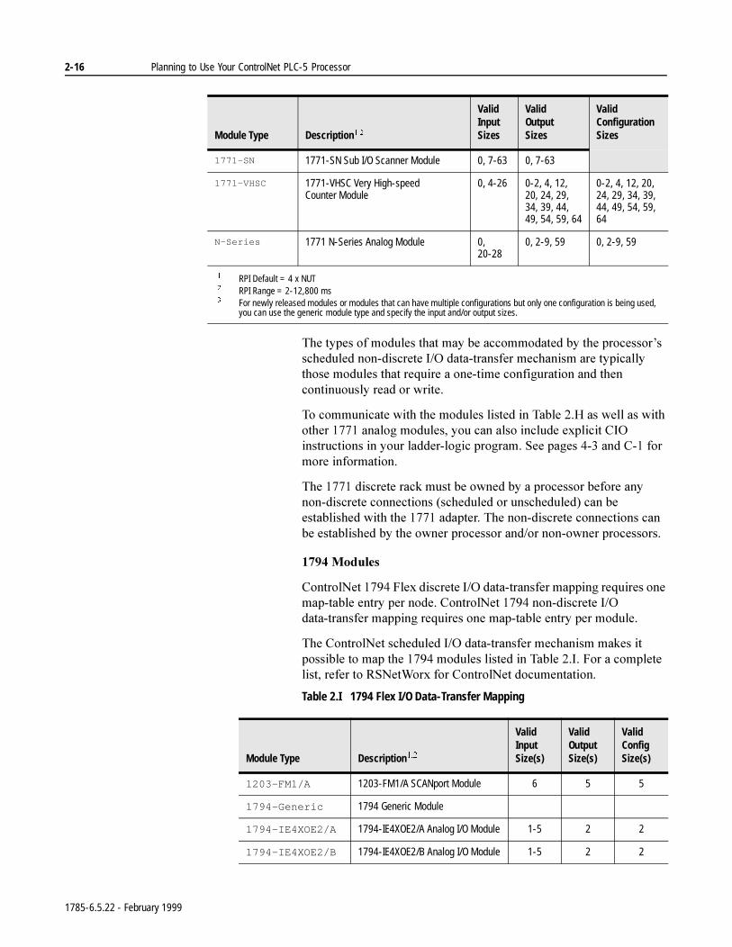
2-16 Planning to Use Your ControlNet PLC-5 Processor
7KHW\SHVRIPRGXOHVWKDWPD\EHDFFRPPRGDWHGE\WKHSURFHVVRU¶VVFKHGXOHGQRQGLVFUHWH,2GDWDWUDQVIHUPHFKDQLVPDUHW\SLFDOO\WKRVHPRGXOHVWKDWUHTXLUHDRQHWLPHFRQILJXUDWLRQDQGWKHQFRQWLQXRXVO\UHDGRUZULWH
7RFRPPXQLFDWHZLWKWKHPRGXOHVOLVWHGLQ7DEOH+DVZHOODVZLWKRWKHUDQDORJPRGXOHV\RXFDQDOVRLQFOXGHH[SOLFLW&,2LQVWUXFWLRQVLQ\RXUODGGHUORJLFSURJUDP6HHSDJHVDQG&IRUPRUHLQIRUPDWLRQ
7KHGLVFUHWHUDFNPXVWEHRZQHGE\DSURFHVVRUEHIRUHDQ\QRQGLVFUHWHFRQQHFWLRQVVFKHGXOHGRUXQVFKHGXOHGFDQEHHVWDEOLVKHGZLWKWKHDGDSWHU7KHQRQGLVFUHWHFRQQHFWLRQVFDQEHHVWDEOLVKHGE\WKHRZQHUSURFHVVRUDQGRUQRQRZQHUSURFHVVRUV
0RGXOHV
&RQWURO1HW)OH[GLVFUHWH,2GDWDWUDQVIHUPDSSLQJUHTXLUHVRQHPDSWDEOHHQWU\SHUQRGH&RQWURO1HWQRQGLVFUHWH,2GDWDWUDQVIHUPDSSLQJUHTXLUHVRQHPDSWDEOHHQWU\SHUPRGXOH
7KH&RQWURO1HWVFKHGXOHG,2GDWDWUDQVIHUPHFKDQLVPPDNHVLWSRVVLEOHWRPDSWKHPRGXOHVOLVWHGLQ7DEOH,)RUDFRPSOHWHOLVWUHIHUWR561HW:RU[IRU&RQWURO1HWGRFXPHQWDWLRQ
Table 2.I 1794 Flex I/O Data-Transfer Mapping
1771-SN 1771-SN Sub I/O Scanner Module 0, 7-63 0, 7-63
1771-VHSC 1771-VHSC Very High-speed Counter Module
0, 4-26 0-2, 4, 12, 20, 24, 29, 34, 39, 44, 49, 54, 59, 64
0-2, 4, 12, 20, 24, 29, 34, 39, 44, 49, 54, 59, 64
N-Series 1771 N-Series Analog Module 0, 20-28
0, 2-9, 59 0, 2-9, 59
RPI Default = 4 x NUT RPI Range = 2-12,800 ms For newly released modules or modules that can have multiple configurations but only one configuration is being used,
you can use the generic module type and specify the input and/or output sizes.
Module Type Description
Valid InputSizes
Valid OutputSizes
Valid ConfigurationSizes
Module Type Description
Valid InputSize(s)
Valid OutputSize(s)
Valid ConfigSize(s)
1203-FM1/A 1203-FM1/A SCANport Module 6 5 5
1794-Generic 1794 Generic Module
1794-IE4XOE2/A 1794-IE4XOE2/A Analog I/O Module 1-5 2 2
1794-IE4XOE2/B 1794-IE4XOE2/B Analog I/O Module 1-5 2 2
1785-6.5.22 - February 1999
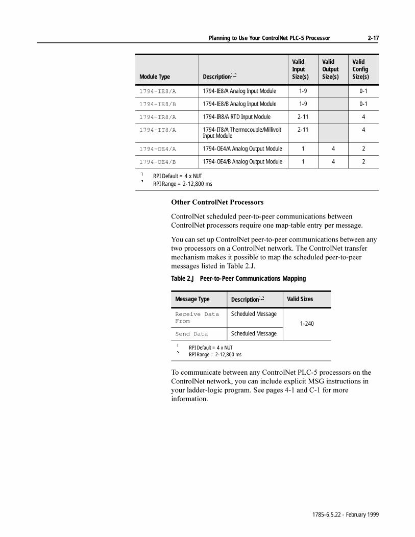
Planning to Use Your ControlNet PLC-5 Processor 2-17
2WKHU&RQWURO1HW3URFHVVRUV
&RQWURO1HWVFKHGXOHGSHHUWRSHHUFRPPXQLFDWLRQVEHWZHHQ&RQWURO1HWSURFHVVRUVUHTXLUHRQHPDSWDEOHHQWU\SHUPHVVDJH
<RXFDQVHWXS&RQWURO1HWSHHUWRSHHUFRPPXQLFDWLRQVEHWZHHQDQ\WZRSURFHVVRUVRQD&RQWURO1HWQHWZRUN7KH&RQWURO1HWWUDQVIHUPHFKDQLVPPDNHVLWSRVVLEOHWRPDSWKHVFKHGXOHGSHHUWRSHHUPHVVDJHVOLVWHGLQ7DEOH-
Table 2.J Peer-to-Peer Communications Mapping
7RFRPPXQLFDWHEHWZHHQDQ\&RQWURO1HW3/&SURFHVVRUVRQWKH&RQWURO1HWQHWZRUN\RXFDQLQFOXGHH[SOLFLW06*LQVWUXFWLRQVLQ\RXUODGGHUORJLFSURJUDP6HHSDJHVDQG&IRUPRUHLQIRUPDWLRQ
1794-IE8/A 1794-IE8/A Analog Input Module 1-9 0-1
1794-IE8/B 1794-IE8/B Analog Input Module 1-9 0-1
1794-IR8/A 1794-IR8/A RTD Input Module 2-11 4
1794-IT8/A 1794-IT8/A Thermocouple/Millivolt Input Module
2-11 4
1794-OE4/A 1794-OE4/A Analog Output Module 1 4 2
1794-OE4/B 1794-OE4/B Analog Output Module 1 4 2
RPI Default = 4 x NUT RPI Range = 2-12,800 ms
Module Type Description
Valid InputSize(s)
Valid OutputSize(s)
Valid ConfigSize(s)
Message Type Description Valid Sizes
Receive Data From
Scheduled Message
1-240
Send Data Scheduled Message
RPI Default = 4 x NUT RPI Range = 2-12,800 ms
1785-6.5.22 - February 1999
2-18 Planning to Use Your ControlNet PLC-5 Processor
Using Process Control Sample Complete
6FKHGXOHGGDWDWUDQVIHUVRFFXUFRQWLQXRXVO\DQGDV\QFKURQRXVO\WRWKHSURJUDPVFDQ,IDVFKHGXOHGFRQQHFWLRQLVDQLQSXWWKHQLQFRPLQJGDWDLVFRSLHGWRDSULYDWHLQSXWEXIIHUXSRQLWVUHFHLSW,IDVFKHGXOHGFRQQHFWLRQLVDQRXWSXWWKHQGDWDIURPDSULYDWHRXWSXWEXIIHULVWUDQVPLWWHGGXULQJHDFKVFKHGXOHGFRPPXQLFDWLRQ<RXUGDWDWDEOHILOHVDQGSULYDWHEXIIHUVDUHV\QFKURQL]HGGXULQJKRXVHNHHSLQJZKLFKRFFXUVEHWZHHQSURJUDPVFDQV'XULQJKRXVHNHHSLQJWKHODWHVWLQSXWVDUHFRSLHGIURPWKHSULYDWHPHPRU\EXIIHUVWRWKHSURFHVVRU¶VLQSXWGDWDWDEOHILOHVILOHDQGWKH',)DQGWKHRXWSXWGDWDWDEOHILOHVILOHDQGWKH'2)DUHFRSLHGWRWKHSULYDWHRXWSXWEXIIHUV
,QVRPHLQVWDQFHVKRZHYHULWLVXVHIXOWRKDYHDFFHVVWRQHZLQSXWGDWDDVVRRQDVLWKDVEHHQUHFHLYHGZLWKRXWZDLWLQJIRUKRXVHNHHSLQJWRWDNHSODFHDWWKHHQGRIWKHSURJUDPVFDQ3URFHVVFRQWUROVDPSOHFRPSOHWHHQDEOHV\RXWRGRVRIRUWKHIROORZLQJVFKHGXOHGFRQQHFWLRQW\SHV
DQDORJRUPRGXOHFRQQHFWLRQ
DQDORJRUPRGXOHFRQQHFWLRQ
DQDORJRUPRGXOHFRQQHFWLRQ
UHFHLYHVFKHGXOHGPHVVDJH
1785-6.5.22 - February 1999
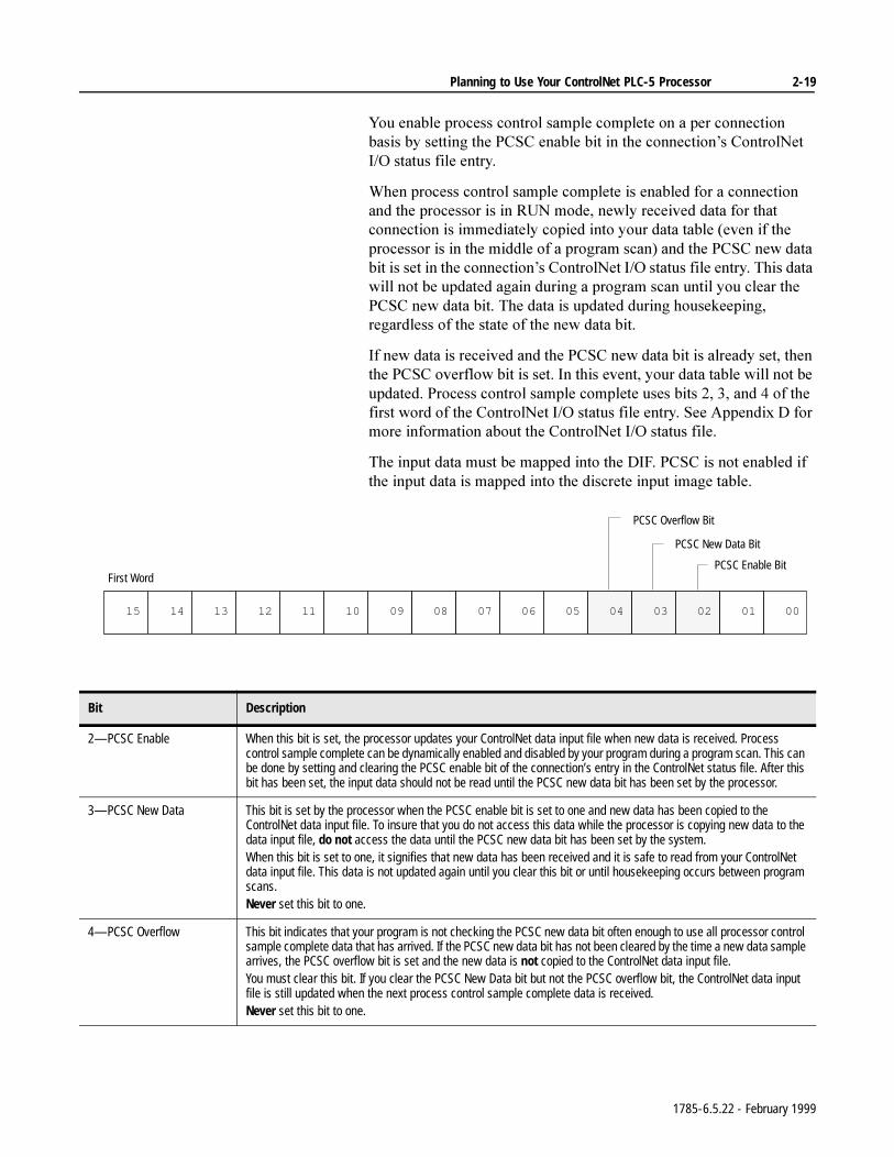
Planning to Use Your ControlNet PLC-5 Processor 2-19
<RXHQDEOHSURFHVVFRQWUROVDPSOHFRPSOHWHRQDSHUFRQQHFWLRQEDVLVE\VHWWLQJWKH3&6&HQDEOHELWLQWKHFRQQHFWLRQ¶V&RQWURO1HW,2VWDWXVILOHHQWU\
:KHQSURFHVVFRQWUROVDPSOHFRPSOHWHLVHQDEOHGIRUDFRQQHFWLRQDQGWKHSURFHVVRULVLQ581PRGHQHZO\UHFHLYHGGDWDIRUWKDWFRQQHFWLRQLVLPPHGLDWHO\FRSLHGLQWR\RXUGDWDWDEOHHYHQLIWKHSURFHVVRULVLQWKHPLGGOHRIDSURJUDPVFDQDQGWKH3&6&QHZGDWDELWLVVHWLQWKHFRQQHFWLRQ¶V&RQWURO1HW,2VWDWXVILOHHQWU\7KLVGDWDZLOOQRWEHXSGDWHGDJDLQGXULQJDSURJUDPVFDQXQWLO\RXFOHDUWKH3&6&QHZGDWDELW7KHGDWDLVXSGDWHGGXULQJKRXVHNHHSLQJUHJDUGOHVVRIWKHVWDWHRIWKHQHZGDWDELW
,IQHZGDWDLVUHFHLYHGDQGWKH3&6&QHZGDWDELWLVDOUHDG\VHWWKHQWKH3&6&RYHUIORZELWLVVHW,QWKLVHYHQW\RXUGDWDWDEOHZLOOQRWEHXSGDWHG3URFHVVFRQWUROVDPSOHFRPSOHWHXVHVELWVDQGRIWKHILUVWZRUGRIWKH&RQWURO1HW,2VWDWXVILOHHQWU\6HH$SSHQGL['IRUPRUHLQIRUPDWLRQDERXWWKH&RQWURO1HW,2VWDWXVILOH
7KHLQSXWGDWDPXVWEHPDSSHGLQWRWKH',)3&6&LVQRWHQDEOHGLIWKHLQSXWGDWDLVPDSSHGLQWRWKHGLVFUHWHLQSXWLPDJHWDEOH
0000102003040500607080091011120131415
First Word
PCSC Overflow Bit
PCSC New Data Bit
PCSC Enable Bit
Bit Description
2—PCSC Enable When this bit is set, the processor updates your ControlNet data input file when new data is received. Process control sample complete can be dynamically enabled and disabled by your program during a program scan. This can be done by setting and clearing the PCSC enable bit of the connection’s entry in the ControlNet status file. After this bit has been set, the input data should not be read until the PCSC new data bit has been set by the processor.
3—PCSC New Data This bit is set by the processor when the PCSC enable bit is set to one and new data has been copied to the ControlNet data input file. To insure that you do not access this data while the processor is copying new data to the data input file, do not access the data until the PCSC new data bit has been set by the system. When this bit is set to one, it signifies that new data has been received and it is safe to read from your ControlNet data input file. This data is not updated again until you clear this bit or until housekeeping occurs between program scans.Never set this bit to one.
4—PCSC Overflow This bit indicates that your program is not checking the PCSC new data bit often enough to use all processor control sample complete data that has arrived. If the PCSC new data bit has not been cleared by the time a new data sample arrives, the PCSC overflow bit is set and the new data is not copied to the ControlNet data input file.You must clear this bit. If you clear the PCSC New Data bit but not the PCSC overflow bit, the ControlNet data input file is still updated when the next process control sample complete data is received. Never set this bit to one.
1785-6.5.22 - February 1999
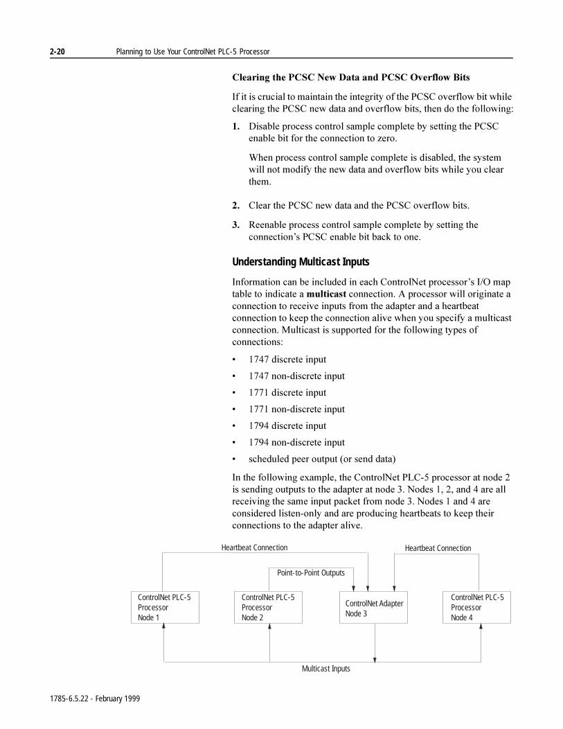
2-20 Planning to Use Your ControlNet PLC-5 Processor
&OHDULQJWKH3&6&1HZ'DWDDQG3&6&2YHUIORZ%LWV
,ILWLVFUXFLDOWRPDLQWDLQWKHLQWHJULW\RIWKH3&6&RYHUIORZELWZKLOHFOHDULQJWKH3&6&QHZGDWDDQGRYHUIORZELWVWKHQGRWKHIROORZLQJ
'LVDEOHSURFHVVFRQWUROVDPSOHFRPSOHWHE\VHWWLQJWKH3&6&HQDEOHELWIRUWKHFRQQHFWLRQWR]HUR
:KHQSURFHVVFRQWUROVDPSOHFRPSOHWHLVGLVDEOHGWKHV\VWHPZLOOQRWPRGLI\WKHQHZGDWDDQGRYHUIORZELWVZKLOH\RXFOHDUWKHP
&OHDUWKH3&6&QHZGDWDDQGWKH3&6&RYHUIORZELWV
5HHQDEOHSURFHVVFRQWUROVDPSOHFRPSOHWHE\VHWWLQJWKHFRQQHFWLRQ¶V3&6&HQDEOHELWEDFNWRRQH
Understanding Multicast Inputs
,QIRUPDWLRQFDQEHLQFOXGHGLQHDFK&RQWURO1HWSURFHVVRU¶V,2PDSWDEOHWRLQGLFDWHDPXOWLFDVWFRQQHFWLRQ$SURFHVVRUZLOORULJLQDWHDFRQQHFWLRQWRUHFHLYHLQSXWVIURPWKHDGDSWHUDQGDKHDUWEHDWFRQQHFWLRQWRNHHSWKHFRQQHFWLRQDOLYHZKHQ\RXVSHFLI\DPXOWLFDVWFRQQHFWLRQ0XOWLFDVWLVVXSSRUWHGIRUWKHIROORZLQJW\SHVRIFRQQHFWLRQV
GLVFUHWHLQSXW
QRQGLVFUHWHLQSXW
GLVFUHWHLQSXW
QRQGLVFUHWHLQSXW
GLVFUHWHLQSXW
QRQGLVFUHWHLQSXW
VFKHGXOHGSHHURXWSXWRUVHQGGDWD
,QWKHIROORZLQJH[DPSOHWKH&RQWURO1HW3/&SURFHVVRUDWQRGHLVVHQGLQJRXWSXWVWRWKHDGDSWHUDWQRGH1RGHVDQGDUHDOOUHFHLYLQJWKHVDPHLQSXWSDFNHWIURPQRGH1RGHVDQGDUHFRQVLGHUHGOLVWHQRQO\DQGDUHSURGXFLQJKHDUWEHDWVWRNHHSWKHLUFRQQHFWLRQVWRWKHDGDSWHUDOLYH
Heartbeat Connection Heartbeat Connection
Point-to-Point Outputs
ControlNet PLC-5ProcessorNode 1
ControlNet PLC-5ProcessorNode 2
ControlNet AdapterNode 3
ControlNet PLC-5ProcessorNode 4
Multicast Inputs
1785-6.5.22 - February 1999
Planning to Use Your ControlNet PLC-5 Processor 2-21
Merged-Save Functionality
:KHQ\RXDGGRUGHOHWHQRGHVRUZKHQ\RXDGGPRGLI\RUGHOHWH,2PDSWDEOHHQWULHVRQO\WKRVHSURFHVVRUVRQWKHQHWZRUNZKRVH&RQWURO1HWVFKHGXOHVQHHGWRFKDQJHDUHUHTXLUHGWREHLQ3URJUDPPRGH7KLVIHDWXUHUHTXLUHV561HW:RU[IRU&RQWURO1HWYHUVLRQRUODWHU
'XULQJWKHVDYHRSHUDWLRQ561HW:RU[JLYHV\RXWZRRSWLRQV
2SWLPL]HVFKHGXOHIRUDOOFRQQHFWLRQV561HW:RU[UHFDOFXODWHVWKH&RQWURO1HWVFKHGXOHIRUDOOWKHQRGHVRQWKH&RQWURO1HWQHWZRUN7KHQHZVFKHGXOHLVGRZQORDGHGWRDOOWKHSURFHVVRUV7KHSURFHVVRUVFORVHDOORIWKHLUH[LVWLQJFRQQHFWLRQVDQGWKHQUHRSHQWKHLUFRQQHFWLRQVDFFRUGLQJWRWKHQHZVFKHGXOH7KLVRSWLRQUHTXLUHVWKDWDOOWKHSURFHVVRUVEHLQ3URJUDPPRGH
0HUJHFKDQJHVLQWRH[LVWLQJVFKHGXOH561HW:RU[PHUJHVWKHSHQGLQJFKDQJHVLQWRWKHFXUUHQW&RQWURO1HWVFKHGXOH7KHQHZVFKHGXOHLVRQO\GRZQORDGHGWRWKRVHSURFHVVRUVWKDWDUHDIIHFWHGE\WKHFKDQJH2QO\WKRVHSURFHVVRUVWKDWDUHDIIHFWHGE\WKHFKDQJHKDYHWREHLQ3URJUDPPRGH$OORWKHUSURFHVVRUVRQWKHQHWZRUNFDQUHPDLQLQ5XQPRGHDQGWKHLUFRQQHFWLRQVUHPDLQRSHQ7KLVRSWLRQLVRQO\DYDLODEOHLIWKHFXUUHQWVFKHGXOHFDQDFFRPPRGDWHWKHSHQGLQJFKDQJHVDQGLIWKH&RQWURO1HWQHWZRUNSDUDPHWHUVVXFKDV187PD[LPXPVFKHGXOHGDGGUHVVPD[LPXPXQVFKHGXOHGDGGUHVVRUPHGLDUHGXQGDQF\GRQRWFKDQJH
3HUIRUPLQJDGRZQORDGYLD561HW:RU[VWLOOUHTXLUHVDOOWKHSURFHVVRUVWREHLQ3URJUDPPRGH
Using I/O Mapping Techniques 'LVFUHWH,2LQWHUIDFHGWRD3/&SURFHVVRULVW\SLFDOO\PDSSHGWRWKH,2LPDJHWDEOHLQSKDVHLWKDGWREHPDSSHGWRWKH,2LPDJHWDEOH<RXFDQPDSGLVFUHWH,2WRWKH',)DQG'2)EXW\RXORVHWKHDELOLW\WRIRUFHWKH,2LIWKH',)RU'2)LVXVHG
(DFKYHUVLRQRIWKH3/&SURFHVVRUKDVDVSHFLILFDPRXQWRI,2LPDJHWDEOHDYDLODEOHDQGWKHUHIRUHDOLPLWRQWKHDPRXQWRI,2WKDWFDQEHPDSSHGWRWKH,2LPDJHWDEOH7UDGLWLRQDOO\HDFKVORWLQDQ,2FKDVVLVLVDVVLJQHGDORFDWLRQLQWKHLQSXWLPDJHWDEOHDQGWKHRXWSXWLPDJHWDEOH:KLOHWKLVSURYLGHVYHU\HDV\PDSSLQJRI,2WRWKHLPDJHWDEOHLWLVQRWWKHPRVWHIILFLHQWZD\WRXVHLW)RUH[DPSOHLIDVORWFRQWDLQVDQLQSXWPRGXOHWKHFRUUHVSRQGLQJORFDWLRQLQWKHRXWSXWLPDJHWDEOHJRHVXQXVHG:LWKWKHLQWURGXFWLRQRIWKH&RQWURO1HWQHWZRUNWRWKH3/&SURFHVVRUIDPLO\QHZWHFKQLTXHVDUHDYDLODEOHWRPDSGLVFUHWH,2LQWRWKH,2LPDJHWDEOHLQDPRUHHIILFLHQWPDQQHU
1785-6.5.22 - February 1999
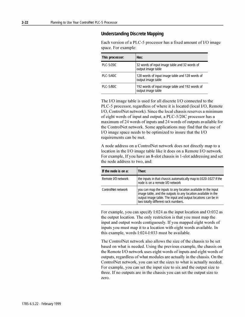
2-22 Planning to Use Your ControlNet PLC-5 Processor
Understanding Discrete Mapping
(DFKYHUVLRQRID3/&SURFHVVRUKDVDIL[HGDPRXQWRI,2LPDJHVSDFH)RUH[DPSOH
7KH,2LPDJHWDEOHLVXVHGIRUDOOGLVFUHWH,2FRQQHFWHGWRWKH3/&SURFHVVRUUHJDUGOHVVRIZKHUHLWLVORFDWHGORFDO,25HPRWH,2&RQWURO1HWQHWZRUN6LQFHWKHORFDOFKDVVLVUHVHUYHVDPLQLPXPRIHLJKWZRUGVRILQSXWDQGRXWSXWD3/&&SURFHVVRUKDVDPD[LPXPRIZRUGVRILQSXWVDQGZRUGVRIRXWSXWVDYDLODEOHIRUWKH&RQWURO1HWQHWZRUN6RPHDSSOLFDWLRQVPD\ILQGWKDWWKHXVHRI,2LPDJHVSDFHQHHGVWREHRSWLPL]HGWRLQVXUHWKDWWKH,2UHTXLUHPHQWVFDQEHPHW
$QRGHDGGUHVVRQD&RQWURO1HWQHWZRUNGRHVQRWGLUHFWO\PDSWRDORFDWLRQLQWKH,2LPDJHWDEOHOLNHLWGRHVRQD5HPRWH,2QHWZRUN)RUH[DPSOH,I\RXKDYHDQVORWFKDVVLVLQVORWDGGUHVVLQJDQGVHWWKHQRGHDGGUHVVWRWZRDQG
)RUH[DPSOH\RXFDQVSHFLI\,DVWKHLQSXWORFDWLRQDQG2DVWKHRXWSXWORFDWLRQ7KHRQO\UHVWULFWLRQLVWKDW\RXPXVWPDSWKHLQSXWDQGRXWSXWZRUGVFRQWLJXRXVO\,I\RXPDSSHGHLJKWZRUGVRILQSXWV\RXPXVWPDSLWWRDORFDWLRQZLWKHLJKWZRUGVDYDLODEOH,QWKLVH[DPSOHZRUGV,,PXVWEHDYDLODEOH
7KH&RQWURO1HWQHWZRUNDOVRDOORZVWKHVL]HRIWKHFKDVVLVWREHVHWEDVHGRQZKDWLVQHHGHG8VLQJWKHSUHYLRXVH[DPSOHWKHFKDVVLVRQWKH5HPRWH,2QHWZRUNXVHVHLJKWZRUGVRILQSXWVDQGHLJKWZRUGVRIRXWSXWVUHJDUGOHVVRIZKDWPRGXOHVDUHDFWXDOO\LQWKHFKDVVLV2QWKH&RQWURO1HWQHWZRUN\RXFDQVHWWKHVL]HVWRZKDWLVDFWXDOO\QHHGHG)RUH[DPSOH\RXFDQVHWWKHLQSXWVL]HWRVL[DQGWKHRXWSXWVL]HWRWKUHH,IQRRXWSXWVDUHLQWKHFKDVVLV\RXFDQVHWWKHRXWSXWVL]HWR]HUR
This processor: Has:
PLC-5/20C 32 words of input image table and 32 words of output image table
PLC-5/40C 128 words of input image table and 128 words of output image table
PLC-5/80C 192 words of input image table and 192 words of output image table
If the node is on a: Then:
Remote I/O network the inputs in that chassis automatically map to I:020-I:027 if the node is on a remote I/O network
ControlNet network you can map the inputs to any location available in the input image table, and the outputs to any location available in the output image table. The input and output locations can be in two totally different rack numbers.
1785-6.5.22 - February 1999
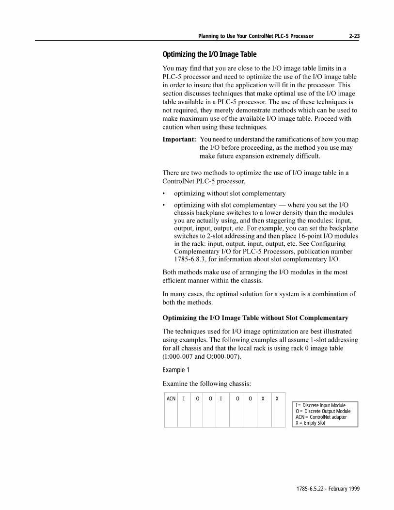
Planning to Use Your ControlNet PLC-5 Processor 2-23
Optimizing the I/O Image Table
<RXPD\ILQGWKDW\RXDUHFORVHWRWKH,2LPDJHWDEOHOLPLWVLQD3/&SURFHVVRUDQGQHHGWRRSWLPL]HWKHXVHRIWKH,2LPDJHWDEOHLQRUGHUWRLQVXUHWKDWWKHDSSOLFDWLRQZLOOILWLQWKHSURFHVVRU7KLVVHFWLRQGLVFXVVHVWHFKQLTXHVWKDWPDNHRSWLPDOXVHRIWKH,2LPDJHWDEOHDYDLODEOHLQD3/&SURFHVVRU7KHXVHRIWKHVHWHFKQLTXHVLVQRWUHTXLUHGWKH\PHUHO\GHPRQVWUDWHPHWKRGVZKLFKFDQEHXVHGWRPDNHPD[LPXPXVHRIWKHDYDLODEOH,2LPDJHWDEOH3URFHHGZLWKFDXWLRQZKHQXVLQJWKHVHWHFKQLTXHV
,PSRUWDQW<RXQHHGWRXQGHUVWDQGWKHUDPLILFDWLRQVRIKRZ\RXPDSWKH,2EHIRUHSURFHHGLQJDVWKHPHWKRG\RXXVHPD\PDNHIXWXUHH[SDQVLRQH[WUHPHO\GLIILFXOW
7KHUHDUHWZRPHWKRGVWRRSWLPL]HWKHXVHRI,2LPDJHWDEOHLQD&RQWURO1HW3/&SURFHVVRU
RSWLPL]LQJZLWKRXWVORWFRPSOHPHQWDU\
RSWLPL]LQJZLWKVORWFRPSOHPHQWDU\²ZKHUH\RXVHWWKH,2FKDVVLVEDFNSODQHVZLWFKHVWRDORZHUGHQVLW\WKDQWKHPRGXOHV\RXDUHDFWXDOO\XVLQJDQGWKHQVWDJJHULQJWKHPRGXOHVLQSXWRXWSXWLQSXWRXWSXWHWF)RUH[DPSOH\RXFDQVHWWKHEDFNSODQHVZLWFKHVWRVORWDGGUHVVLQJDQGWKHQSODFHSRLQW,2PRGXOHVLQWKHUDFNLQSXWRXWSXWLQSXWRXWSXWHWF6HH&RQILJXULQJ&RPSOHPHQWDU\,2IRU3/&3URFHVVRUVSXEOLFDWLRQQXPEHUIRULQIRUPDWLRQDERXWVORWFRPSOHPHQWDU\,2
%RWKPHWKRGVPDNHXVHRIDUUDQJLQJWKH,2PRGXOHVLQWKHPRVWHIILFLHQWPDQQHUZLWKLQWKHFKDVVLV
,QPDQ\FDVHVWKHRSWLPDOVROXWLRQIRUDV\VWHPLVDFRPELQDWLRQRIERWKWKHPHWKRGV
2SWLPL]LQJWKH,2,PDJH7DEOHZLWKRXW6ORW&RPSOHPHQWDU\
7KHWHFKQLTXHVXVHGIRU,2LPDJHRSWLPL]DWLRQDUHEHVWLOOXVWUDWHGXVLQJH[DPSOHV7KHIROORZLQJH[DPSOHVDOODVVXPHVORWDGGUHVVLQJIRUDOOFKDVVLVDQGWKDWWKHORFDOUDFNLVXVLQJUDFNLPDJHWDEOH,DQG2
Example 1
([DPLQHWKHIROORZLQJFKDVVLV
ACN I O O I O OI = Discrete Input ModuleO = Discrete Output ModuleACN = ControlNet adapterX = Empty Slot
X X
1785-6.5.22 - February 1999
2-24 Planning to Use Your ControlNet PLC-5 Processor
,I\RXSHUIRUPDQDXWRPDSRQWKLVV\VWHPWKHPDSWDEOHDSSHDUVOLNHWKLV
7KHDXWRPDSIHDWXUHUHVHUYHVWKHPD[LPXPVL]HRILQSXWVDQGRXWSXWV,WLVXSWR\RXWRPDQXDOO\FKDQJHWKHVL]HVLIGHVLUHG,I\RXRSWLPL]HWKHFKDVVLVDVVKRZQWKHVL]HVDGMXVWWRWKHIROORZLQJ
7KHUHDUHWZRLQSXWPRGXOHVDQGIRXURXWSXWPRGXOHVLQWKHFKDVVLV+RZHYHU\RXFDQQRWVHWWKHVL]HVWRWZRDQGIRXUEHFDXVHWKHDGGUHVV\RXVSHFLI\LVWKHVWDUWLQJDGGUHVVRIWKHFKDVVLV,WLGHQWLILHVWKHDGGUHVVRIWKHOHIWPRVWVORW7KHVL]H\RXVSHFLI\GHWHUPLQHVKRZPDQ\VORWVLQWKHFKDVVLVZULWWHQWRRUUHDGIURP,QVORWDGGUHVVLQJZRUGVHTXDOVVORWV7KHFRQFHSWLVWKHVDPHIRUDQ\DGGUHVVLQJPRGH:RUGVDUHUHDGZULWWHQIURPOHIWWRZULWH,QVORWDGGUHVVLQJWKHUHDUHWZRZRUGVSHUVORW
,QWKLVH[DPSOHWKHILUVWVORWLQWKHFKDVVLVLV,2WKHVHFRQGVORW,2DQGVRRQ7KHILIWKVORWLV2RQO\<RXFDQQRWSODFHDQLQSXWPRGXOHLQWKLVVORWVLQFHQRLQSXWZRUGLVPDSSHGWRLW7KHVHYHQWKVORWKDVQR,2LPDJHWDEOHPDSSHGWRLW<RXFDQQRWSODFHDGLVFUHWHLQSXWRURXWSXWPRGXOHLQWKHODVWWZRVORWVVLQFHWKHUHLVQR,2LPDJHWDEOHDOORFDWHGWRLW
Input file Input size Output file Output size
I:010 8 O:010 8
Input file Input size Output file Output size
I:010 4 O:010 6
1785-6.5.22 - February 1999
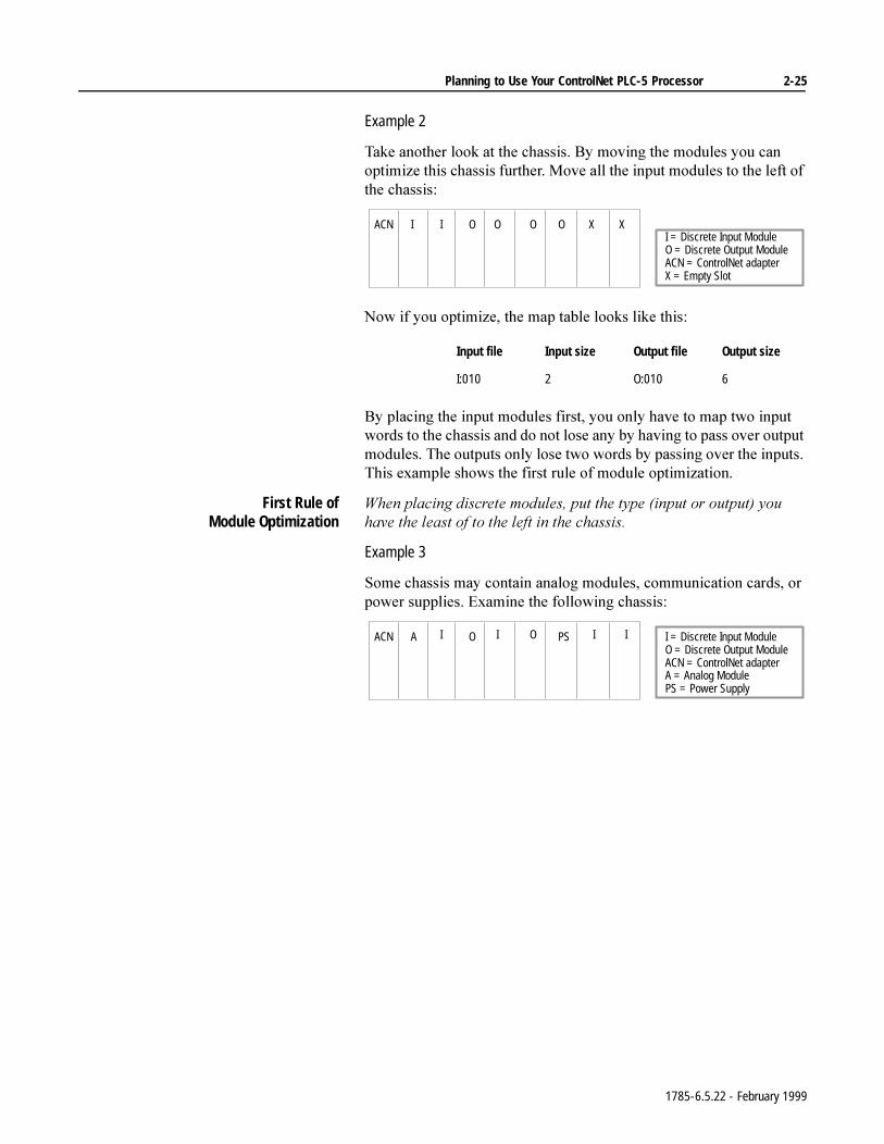
Planning to Use Your ControlNet PLC-5 Processor 2-25
Example 2
7DNHDQRWKHUORRNDWWKHFKDVVLV%\PRYLQJWKHPRGXOHV\RXFDQRSWLPL]HWKLVFKDVVLVIXUWKHU0RYHDOOWKHLQSXWPRGXOHVWRWKHOHIWRIWKHFKDVVLV
1RZLI\RXRSWLPL]HWKHPDSWDEOHORRNVOLNHWKLV
%\SODFLQJWKHLQSXWPRGXOHVILUVW\RXRQO\KDYHWRPDSWZRLQSXWZRUGVWRWKHFKDVVLVDQGGRQRWORVHDQ\E\KDYLQJWRSDVVRYHURXWSXWPRGXOHV7KHRXWSXWVRQO\ORVHWZRZRUGVE\SDVVLQJRYHUWKHLQSXWV7KLVH[DPSOHVKRZVWKHILUVWUXOHRIPRGXOHRSWLPL]DWLRQ
First Rule ofModule Optimization
:KHQSODFLQJGLVFUHWHPRGXOHVSXWWKHW\SHLQSXWRURXWSXW\RXKDYHWKHOHDVWRIWRWKHOHIWLQWKHFKDVVLV
Example 3
6RPHFKDVVLVPD\FRQWDLQDQDORJPRGXOHVFRPPXQLFDWLRQFDUGVRUSRZHUVXSSOLHV([DPLQHWKHIROORZLQJFKDVVLV
Input file Input size Output file Output size
I:010 2 O:010 6
ACN I I O O O OI = Discrete Input ModuleO = Discrete Output ModuleACN = ControlNet adapterX = Empty Slot
X X
ACN A I O I O PS I = Discrete Input ModuleO = Discrete Output ModuleACN = ControlNet adapterA = Analog ModulePS = Power Supply
I I
1785-6.5.22 - February 1999
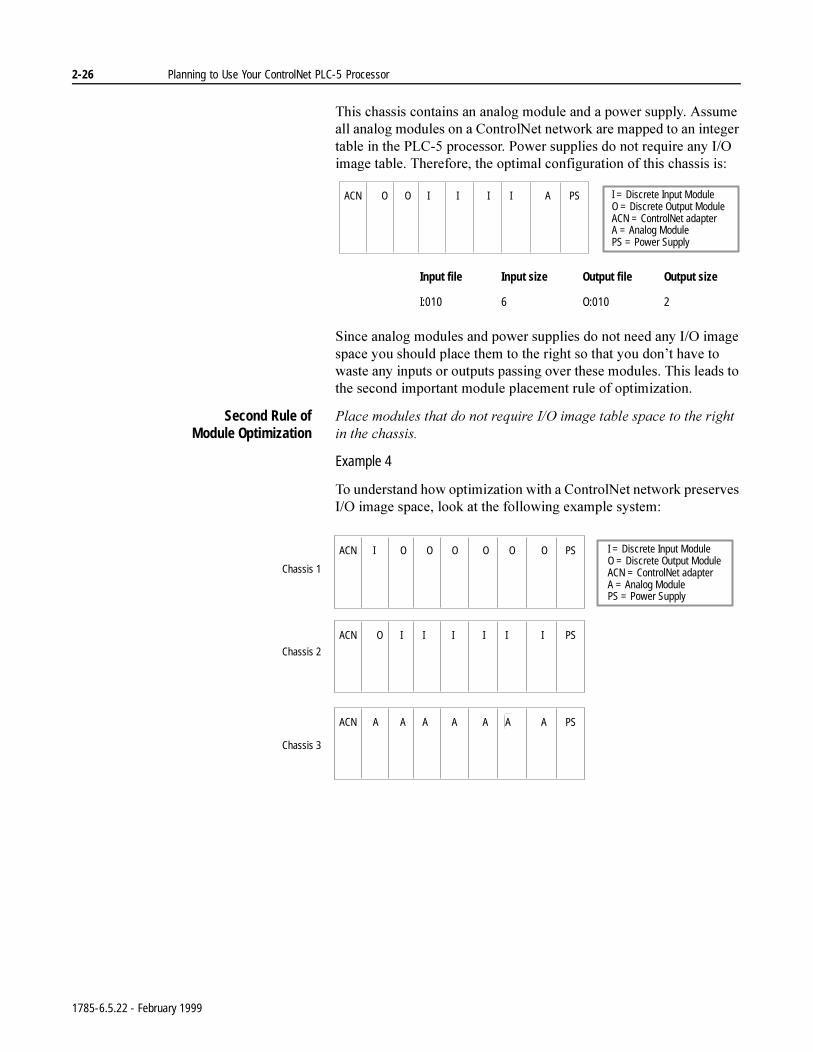
2-26 Planning to Use Your ControlNet PLC-5 Processor
7KLVFKDVVLVFRQWDLQVDQDQDORJPRGXOHDQGDSRZHUVXSSO\$VVXPHDOODQDORJPRGXOHVRQD&RQWURO1HWQHWZRUNDUHPDSSHGWRDQLQWHJHUWDEOHLQWKH3/&SURFHVVRU3RZHUVXSSOLHVGRQRWUHTXLUHDQ\,2LPDJHWDEOH7KHUHIRUHWKHRSWLPDOFRQILJXUDWLRQRIWKLVFKDVVLVLV
6LQFHDQDORJPRGXOHVDQGSRZHUVXSSOLHVGRQRWQHHGDQ\,2LPDJHVSDFH\RXVKRXOGSODFHWKHPWRWKHULJKWVRWKDW\RXGRQ¶WKDYHWRZDVWHDQ\LQSXWVRURXWSXWVSDVVLQJRYHUWKHVHPRGXOHV7KLVOHDGVWRWKHVHFRQGLPSRUWDQWPRGXOHSODFHPHQWUXOHRIRSWLPL]DWLRQ
Second Rule ofModule Optimization
3ODFHPRGXOHVWKDWGRQRWUHTXLUH,2LPDJHWDEOHVSDFHWRWKHULJKWLQWKHFKDVVLV
Example 4
7RXQGHUVWDQGKRZRSWLPL]DWLRQZLWKD&RQWURO1HWQHWZRUNSUHVHUYHV,2LPDJHVSDFHORRNDWWKHIROORZLQJH[DPSOHV\VWHP
Input file Input size Output file Output size
I:010 6 O:010 2
ACN O O I I I I I = Discrete Input ModuleO = Discrete Output ModuleACN = ControlNet adapterA = Analog ModulePS = Power Supply
A PS
I = Discrete Input ModuleO = Discrete Output ModuleACN = ControlNet adapterA = Analog ModulePS = Power Supply
Chassis 1
Chassis 2
Chassis 3
ACN A A A A A a A PSAA
ACN I O O O O O O PS
ACN O I I I I I I PS
1785-6.5.22 - February 1999
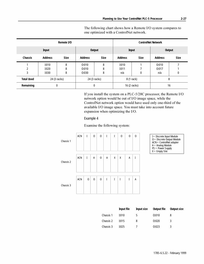
Planning to Use Your ControlNet PLC-5 Processor 2-27
7KHIROORZLQJFKDUWVKRZVKRZD5HPRWH,2V\VWHPFRPSDUHVWRRQHRSWLPL]HGZLWKD&RQWURO1HWQHWZRUN
,I\RXLQVWDOOWKHV\VWHPRQD3/&&SURFHVVRUWKH5HPRWH,2QHWZRUNRSWLRQZRXOGEHRXWRI,2LPDJHVSDFHZKLOHWKH&RQWURO1HWQHWZRUNRSWLRQZRXOGKDYHXVHGRQO\RQHWKLUGRIWKHDYDLODEOH,2LPDJHVSDFH<RXPXVWWDNHLQWRDFFRXQWIXWXUHH[SDQVLRQZKHQRSWLPL]LQJWKH,2
Example 4
([DPLQHWKHIROORZLQJV\VWHP
Remote I/O ControlNet Network
Input Output Input Output
Chassis Address Size Address Size Address Size Address Size
123
I:010I:020I:030
888
O:010O:010O:030
888
I:010I:011n/a
170
O:010O:017
n/a
710
Total Used 24 (3 racks) 24 (3 racks) 8 (1 rack) 8
Remaining 0 0 16 (2 racks) 16
I O O I I O I = Discrete Input ModuleO = Discrete Output ModuleACN = ControlNet adapterA = Analog ModulePS = Power SupplyX = Empty Slot
O O
I A O A X X A I
Chassis 1
Chassis 2
Chassis 3
O O O I I I I A
ACN
ACN
ACN
Input file Input size Output file Output size
Chassis 1 I:010 5 O:010 8
Chassis 2 I:015 8 O:020 3
Chassis 3 I:025 7 O:023 3
1785-6.5.22 - February 1999
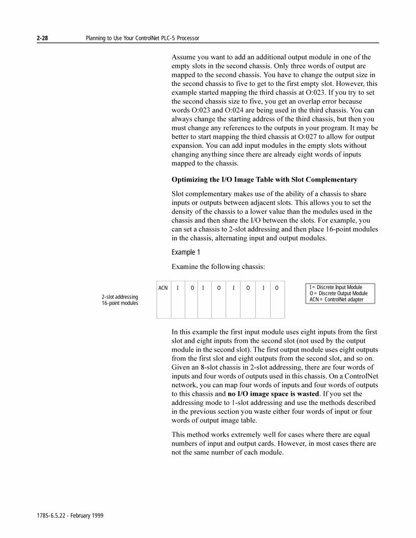
2-28 Planning to Use Your ControlNet PLC-5 Processor
$VVXPH\RXZDQWWRDGGDQDGGLWLRQDORXWSXWPRGXOHLQRQHRIWKHHPSW\VORWVLQWKHVHFRQGFKDVVLV2QO\WKUHHZRUGVRIRXWSXWDUHPDSSHGWRWKHVHFRQGFKDVVLV<RXKDYHWRFKDQJHWKHRXWSXWVL]HLQWKHVHFRQGFKDVVLVWRILYHWRJHWWRWKHILUVWHPSW\VORW+RZHYHUWKLVH[DPSOHVWDUWHGPDSSLQJWKHWKLUGFKDVVLVDW2,I\RXWU\WRVHWWKHVHFRQGFKDVVLVVL]HWRILYH\RXJHWDQRYHUODSHUURUEHFDXVHZRUGV2DQG2DUHEHLQJXVHGLQWKHWKLUGFKDVVLV<RXFDQDOZD\VFKDQJHWKHVWDUWLQJDGGUHVVRIWKHWKLUGFKDVVLVEXWWKHQ\RXPXVWFKDQJHDQ\UHIHUHQFHVWRWKHRXWSXWVLQ\RXUSURJUDP,WPD\EHEHWWHUWRVWDUWPDSSLQJWKHWKLUGFKDVVLVDW2WRDOORZIRURXWSXWH[SDQVLRQ<RXFDQDGGLQSXWPRGXOHVLQWKHHPSW\VORWVZLWKRXWFKDQJLQJDQ\WKLQJVLQFHWKHUHDUHDOUHDG\HLJKWZRUGVRILQSXWVPDSSHGWRWKHFKDVVLV
2SWLPL]LQJWKH,2,PDJH7DEOHZLWK6ORW&RPSOHPHQWDU\
6ORWFRPSOHPHQWDU\PDNHVXVHRIWKHDELOLW\RIDFKDVVLVWRVKDUHLQSXWVRURXWSXWVEHWZHHQDGMDFHQWVORWV7KLVDOORZV\RXWRVHWWKHGHQVLW\RIWKHFKDVVLVWRDORZHUYDOXHWKDQWKHPRGXOHVXVHGLQWKHFKDVVLVDQGWKHQVKDUHWKH,2EHWZHHQWKHVORWV)RUH[DPSOH\RXFDQVHWDFKDVVLVWRVORWDGGUHVVLQJDQGWKHQSODFHSRLQWPRGXOHVLQWKHFKDVVLVDOWHUQDWLQJLQSXWDQGRXWSXWPRGXOHV
Example 1
([DPLQHWKHIROORZLQJFKDVVLV
,QWKLVH[DPSOHWKHILUVWLQSXWPRGXOHXVHVHLJKWLQSXWVIURPWKHILUVWVORWDQGHLJKWLQSXWVIURPWKHVHFRQGVORWQRWXVHGE\WKHRXWSXWPRGXOHLQWKHVHFRQGVORW7KHILUVWRXWSXWPRGXOHXVHVHLJKWRXWSXWVIURPWKHILUVWVORWDQGHLJKWRXWSXWVIURPWKHVHFRQGVORWDQGVRRQ*LYHQDQVORWFKDVVLVLQVORWDGGUHVVLQJWKHUHDUHIRXUZRUGVRILQSXWVDQGIRXUZRUGVRIRXWSXWVXVHGLQWKLVFKDVVLV2QD&RQWURO1HWQHWZRUN\RXFDQPDSIRXUZRUGVRILQSXWVDQGIRXUZRUGVRIRXWSXWVWRWKLVFKDVVLVDQGQR,2LPDJHVSDFHLVZDVWHG,I\RXVHWWKHDGGUHVVLQJPRGHWRVORWDGGUHVVLQJDQGXVHWKHPHWKRGVGHVFULEHGLQWKHSUHYLRXVVHFWLRQ\RXZDVWHHLWKHUIRXUZRUGVRILQSXWRUIRXUZRUGVRIRXWSXWLPDJHWDEOH
7KLVPHWKRGZRUNVH[WUHPHO\ZHOOIRUFDVHVZKHUHWKHUHDUHHTXDOQXPEHUVRILQSXWDQGRXWSXWFDUGV+RZHYHULQPRVWFDVHVWKHUHDUHQRWWKHVDPHQXPEHURIHDFKPRGXOH
I O I O I O I = Discrete Input ModuleO = Discrete Output ModuleACN = ControlNet adapter
I OACN
2-slot addressing16-point modules
1785-6.5.22 - February 1999
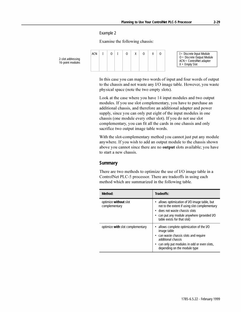
Planning to Use Your ControlNet PLC-5 Processor 2-29
Example 2
([DPLQHWKHIROORZLQJFKDVVLV
,QWKLVFDVH\RXFDQPDSWZRZRUGVRILQSXWDQGIRXUZRUGVRIRXWSXWWRWKHFKDVVLVDQGQRWZDVWHDQ\,2LPDJHWDEOH+RZHYHU\RXZDVWHSK\VLFDOVSDFHQRWHWKHWZRHPSW\VORWV
/RRNDWWKHFDVHZKHUH\RXKDYHLQSXWPRGXOHVDQGWZRRXWSXWPRGXOHV,I\RXXVHVORWFRPSOHPHQWDU\\RXKDYHWRSXUFKDVHDQDGGLWLRQDOFKDVVLVDQGWKHUHIRUHDQDGGLWLRQDODGDSWHUDQGSRZHUVXSSO\VLQFH\RXFDQRQO\SXWHLJKWRIWKHLQSXWPRGXOHVLQRQHFKDVVLVRQHPRGXOHHYHU\RWKHUVORW,I\RXGRQRWXVHVORWFRPSOHPHQWDU\\RXFDQILWDOOWKHFDUGVLQRQHFKDVVLVDQGRQO\VDFULILFHWZRRXWSXWLPDJHWDEOHZRUGV
:LWKWKHVORWFRPSOHPHQWDU\PHWKRG\RXFDQQRWMXVWSXWDQ\PRGXOHDQ\ZKHUH,I\RXZLVKWRDGGDQRXWSXWPRGXOHWRWKHFKDVVLVVKRZQDERYH\RXFDQQRWVLQFHWKHUHDUHQRRXWSXWVORWVDYDLODEOH\RXKDYHWRVWDUWDQHZFKDVVLV
Summary
7KHUHDUHWZRPHWKRGVWRRSWLPL]HWKHXVHRI,2LPDJHWDEOHLQD&RQWURO1HW3/&SURFHVVRU7KHUHDUHWUDGHRIIVLQXVLQJHDFKPHWKRGZKLFKDUHVXPPDUL]HGLQWKHIROORZLQJWDEOH
I O I O X O I = Discrete Input ModuleO = Discrete Output ModuleACN = ControlNet adapterX = Empty Slot
X OACN
2-slot addressing16-point modules
Method: Tradeoffs:
optimize without slot complementary
• allows optimization of I/O image table, but not to the extent if using slot complementary
• does not waste chassis slots• can put any module anywhere (provided I/O
table exists for that slot)
optimize with slot complementary • allows complete optimization of the I/O image table
• can waste chassis slots and require additional chassis
• can only put modules in odd or even slots, depending on the module type
1785-6.5.22 - February 1999
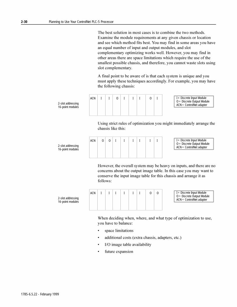
2-30 Planning to Use Your ControlNet PLC-5 Processor
7KHEHVWVROXWLRQLQPRVWFDVHVLVWRFRPELQHWKHWZRPHWKRGV([DPLQHWKHPRGXOHUHTXLUHPHQWVDWDQ\JLYHQFKDVVLVRUORFDWLRQDQGVHHZKLFKPHWKRGILWVEHVW<RXPD\ILQGLQVRPHDUHDV\RXKDYHDQHTXDOQXPEHURILQSXWDQGRXWSXWPRGXOHVDQGVORWFRPSOHPHQWDU\RSWLPL]LQJZRUNVZHOO+RZHYHU\RXPD\ILQGLQRWKHUDUHDVWKHUHDUHVSDFHOLPLWDWLRQVZKLFKUHTXLUHWKHXVHRIWKHVPDOOHVWSRVVLEOHFKDVVLVDQGWKHUHIRUH\RXFDQQRWZDVWHVORWVXVLQJVORWFRPSOHPHQWDU\
$ILQDOSRLQWWREHDZDUHRILVWKDWHDFKV\VWHPLVXQLTXHDQG\RXPXVWDSSO\WKHVHWHFKQLTXHVDFFRUGLQJO\)RUH[DPSOH\RXPD\KDYHWKHIROORZLQJFKDVVLV
8VLQJVWULFWUXOHVRIRSWLPL]DWLRQ\RXPLJKWLPPHGLDWHO\DUUDQJHWKHFKDVVLVOLNHWKLV
+RZHYHUWKHRYHUDOOV\VWHPPD\EHKHDY\RQLQSXWVDQGWKHUHDUHQRFRQFHUQVDERXWWKHRXWSXWLPDJHWDEOH,QWKLVFDVH\RXPD\ZDQWWRFRQVHUYHWKHLQSXWLPDJHWDEOHIRUWKLVFKDVVLVDQGDUUDQJHLWDVIROORZV
:KHQGHFLGLQJZKHQZKHUHDQGZKDWW\SHRIRSWLPL]DWLRQWRXVH\RXKDYHWREDODQFH
VSDFHOLPLWDWLRQV
DGGLWLRQDOFRVWVH[WUDFKDVVLVDGDSWHUVHWF
,2LPDJHWDEOHDYDLODELOLW\
IXWXUHH[SDQVLRQ
I I O I I I I = Discrete Input ModuleO = Discrete Output ModuleACN = ControlNet adapter
O IACN
2-slot addressing16-point modules
O O I I I I I = Discrete Input ModuleO = Discrete Output ModuleACN = ControlNet adapter
I IACN
2-slot addressing16-point modules
I I I I I I I = Discrete Input ModuleO = Discrete Output ModuleACN = ControlNet adapter
O OACN
2-slot addressing16-point modules
1785-6.5.22 - February 1999
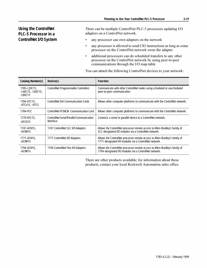
Planning to Use Your ControlNet PLC-5 Processor 2-31
Using the ControlNetPLC-5 Processor in aControlNet I/O System
7KHUHFDQEHPXOWLSOH&RQWURO1HW3/&SURFHVVRUVXSGDWLQJ,2DGDSWHUVRQD&RQWURO1HWQHWZRUN
DQ\SURFHVVRUFDQRZQDGDSWHUVRQWKHQHWZRUN
DQ\SURFHVVRULVDOORZHGWRVHQG&,2LQVWUXFWLRQVDVORQJDVVRPHSURFHVVRURQWKH&RQWURO1HWQHWZRUNRZQVWKHDGDSWHU
DGGLWLRQDOSURFHVVRUVFDQGRVFKHGXOHGWUDQVIHUVWRDQ\RWKHUSURFHVVRURQWKH&RQWURO1HWQHWZRUNE\XVLQJSHHUWRSHHUFRPPXQLFDWLRQVWKURXJKWKH,2PDSWDEOH
<RXFDQDWWDFKWKHIROORZLQJ&RQWURO1HWGHYLFHVWR\RXUQHWZRUN
7KHUHDUHRWKHUSURGXFWVDYDLODEOHIRULQIRUPDWLRQDERXWWKHVHSURGXFWVFRQWDFW\RXUORFDO5RFNZHOO$XWRPDWLRQVDOHVRIILFH
Catalog Number(s) Device(s) Function
1785-L20C15, -L40C15, -L60C15, -L80C15
ControlNet Programmable Controllers Communicate with other ControlNet nodes using scheduled or unscheduled peer-to-peer communication
1784-KTC15, -KTCx15, -KTCS
ControlNet ISA Communication Cards Allows other computer platforms to communicate with the ControlNet network.
1784-PCC ControlNet PCMCIA Communication Card Allows other computer platforms to communicate with the ControlNet network.
1770-KFC15,-KFCD15
ControlNet Serial/Parallel Communication Interface
Connects a serial or parallel device to a ControlNet network.
1747-ACN15, -ACNR15
1747 ControlNet SLC I/O Adapters Allows the ControlNet processor remote access to Allen-Bradley’s family of SLC-designated I/O modules via a ControlNet network.
1771-ACN15, -ACNR15
1771 ControlNet I/O Adapters Allows the ControlNet processor remote access to Allen-Bradley’s family of 1771-designated I/O modules via a ControlNet network.
1794-ACN15, -ACNR15
1794 ControlNet Flex I/O Adapters Allows the ControlNet processor remote access to Allen-Bradley’s family of 1794-designated I/O modules via a ControlNet network.
1785-6.5.22 - February 1999
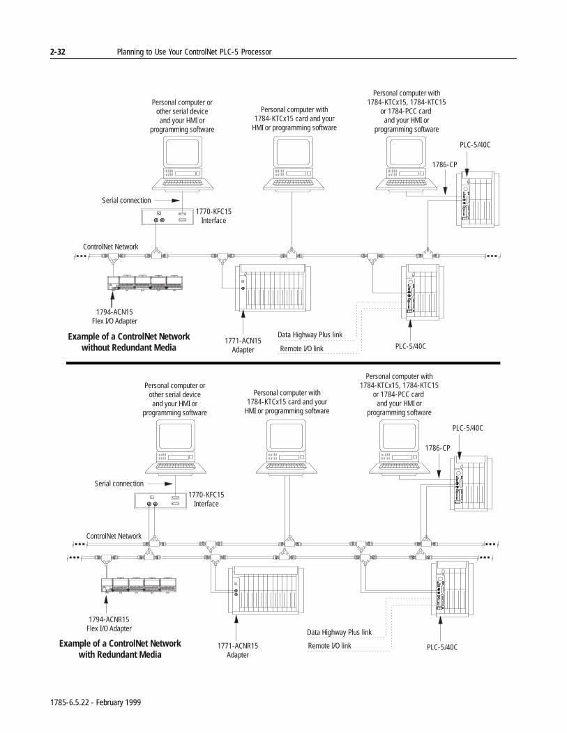
2-32 Planning to Use Your ControlNet PLC-5 Processor
Personal computer with1784-KTCx15 card and your
HMI or programming software
Personal computer orother serial deviceand your HMI or
programming software
Personal computer with1784-KTCx15, 1784-KTC15
or 1784-PCC card and your HMI or
programming software
Serial connection
1770-KFC15Interface
PLC-5/40C
ControlNet Network
1794-ACNR15Flex I/O Adapter
1771-ACNR15Adapter
Data Highway Plus link
Remote I/O link PLC-5/40C
1786-CP
Example of a ControlNet Networkwith Redundant Media
Personal computer with1784-KTCx15 card and your
HMI or programming software
Personal computer orother serial deviceand your HMI or
programming software
Personal computer with1784-KTCx15, 1784-KTC15
or 1784-PCC card and your HMI or
programming software
Serial connection
1770-KFC15Interface
PLC-5/40C
ControlNet Network
1794-ACN15Flex I/O Adapter
1771-ACN15Adapter
Data Highway Plus link
Remote I/O link PLC-5/40C
1786-CP
Example of a ControlNet Networkwithout Redundant Media
1785-6.5.22 - February 1999
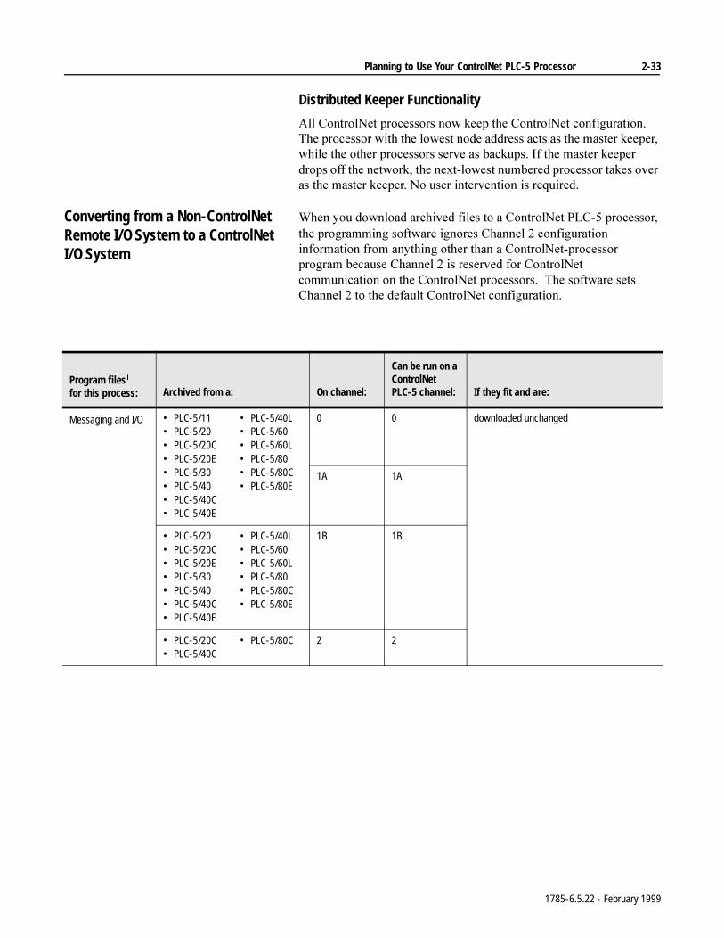
Planning to Use Your ControlNet PLC-5 Processor 2-33
Distributed Keeper Functionality
$OO&RQWURO1HWSURFHVVRUVQRZNHHSWKH&RQWURO1HWFRQILJXUDWLRQ7KHSURFHVVRUZLWKWKHORZHVWQRGHDGGUHVVDFWVDVWKHPDVWHUNHHSHUZKLOHWKHRWKHUSURFHVVRUVVHUYHDVEDFNXSV,IWKHPDVWHUNHHSHUGURSVRIIWKHQHWZRUNWKHQH[WORZHVWQXPEHUHGSURFHVVRUWDNHVRYHUDVWKHPDVWHUNHHSHU1RXVHULQWHUYHQWLRQLVUHTXLUHG
Converting from a Non-ControlNet Remote I/O System to a ControlNet I/O System
:KHQ\RXGRZQORDGDUFKLYHGILOHVWRD&RQWURO1HW3/&SURFHVVRUWKHSURJUDPPLQJVRIWZDUHLJQRUHV&KDQQHOFRQILJXUDWLRQLQIRUPDWLRQIURPDQ\WKLQJRWKHUWKDQD&RQWURO1HWSURFHVVRUSURJUDPEHFDXVH&KDQQHOLVUHVHUYHGIRU&RQWURO1HWFRPPXQLFDWLRQRQWKH&RQWURO1HWSURFHVVRUV7KHVRIWZDUHVHWV&KDQQHOWRWKHGHIDXOW&RQWURO1HWFRQILJXUDWLRQ
Program files for this process: Archived from a: On channel:
Can be run on a ControlNet PLC-5 channel: If they fit and are:
Messaging and I/O • PLC-5/11• PLC-5/20• PLC-5/20C• PLC-5/20E• PLC-5/30• PLC-5/40• PLC-5/40C• PLC-5/40E
• PLC-5/40L• PLC-5/60• PLC-5/60L• PLC-5/80• PLC-5/80C• PLC-5/80E
0 0 downloaded unchanged
1A 1A
• PLC-5/20• PLC-5/20C• PLC-5/20E• PLC-5/30• PLC-5/40• PLC-5/40C• PLC-5/40E
• PLC-5/40L• PLC-5/60• PLC-5/60L• PLC-5/80• PLC-5/80C• PLC-5/80E
1B 1B
• PLC-5/20C• PLC-5/40C
• PLC-5/80C 2 2
1785-6.5.22 - February 1999
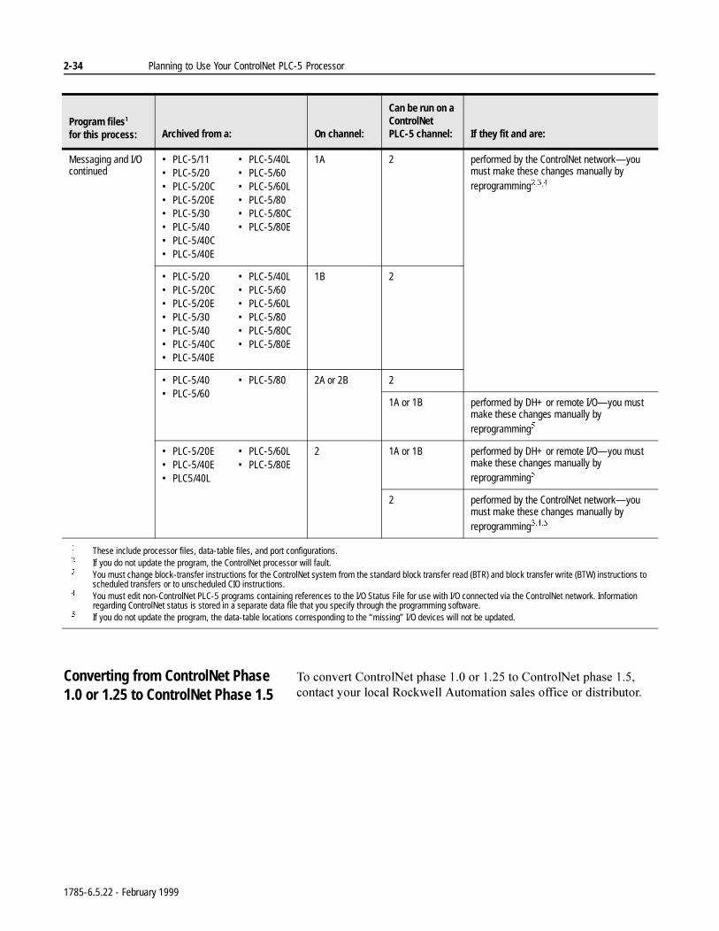
2-34 Planning to Use Your ControlNet PLC-5 Processor
Converting from ControlNet Phase 1.0 or 1.25 to ControlNet Phase 1.5
7RFRQYHUW&RQWURO1HWSKDVHRUWR&RQWURO1HWSKDVHFRQWDFW\RXUORFDO5RFNZHOO$XWRPDWLRQVDOHVRIILFHRUGLVWULEXWRU
Messaging and I/Ocontinued
• PLC-5/11• PLC-5/20• PLC-5/20C• PLC-5/20E• PLC-5/30• PLC-5/40• PLC-5/40C• PLC-5/40E
• PLC-5/40L• PLC-5/60• PLC-5/60L• PLC-5/80• PLC-5/80C• PLC-5/80E
1A 2 performed by the ControlNet network—you must make these changes manually by reprogramming
• PLC-5/20• PLC-5/20C• PLC-5/20E• PLC-5/30• PLC-5/40• PLC-5/40C• PLC-5/40E
• PLC-5/40L• PLC-5/60• PLC-5/60L• PLC-5/80• PLC-5/80C• PLC-5/80E
1B 2
• PLC-5/40• PLC-5/60
• PLC-5/80 2A or 2B 2
1A or 1B performed by DH+ or remote I/O—you must make these changes manually by reprogramming
• PLC-5/20E• PLC-5/40E• PLC5/40L
• PLC-5/60L• PLC-5/80E
2 1A or 1B performed by DH+ or remote I/O—you must make these changes manually by reprogramming
2 performed by the ControlNet network—you must make these changes manually by reprogramming
These include processor files, data-table files, and port configurations. If you do not update the program, the ControlNet processor will fault. You must change block-transfer instructions for the ControlNet system from the standard block transfer read (BTR) and block transfer write (BTW) instructions to
scheduled transfers or to unscheduled CIO instructions. You must edit non-ControlNet PLC-5 programs containing references to the I/O Status File for use with I/O connected via the ControlNet network. Information
regarding ControlNet status is stored in a separate data file that you specify through the programming software. If you do not update the program, the data-table locations corresponding to the “missing” I/O devices will not be updated.
Program files for this process: Archived from a: On channel:
Can be run on a ControlNet PLC-5 channel: If they fit and are:
1785-6.5.22 - February 1999
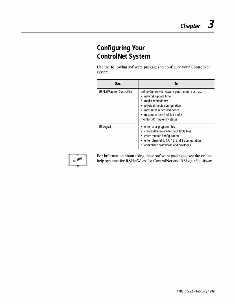
Chapter 3
Configuring Your ControlNet System8VHWKHIROORZLQJVRIWZDUHSDFNDJHVWRFRQILJXUH\RXU&RQWURO1HWV\VWHP
)RULQIRUPDWLRQDERXWXVLQJWKHVHVRIWZDUHSDFNDJHVVHHWKHRQOLQHKHOSV\VWHPVIRU561HW:RU[IRU&RQWURO1HWDQG56/RJL[VRIWZDUH
Use: To:
RSNetWorx for ControlNet define ControlNet network parameters, such as:• network update time• media redundancy• physical media configuration• maximum scheduled nodes• maximum unscheduled nodesmonitor I/O map entry status
RSLogix5 • enter user program files• create/delete/monitor data table files• enter module configuration• enter channel 0, 1A, 1B, and 3 configuration• administer passwords and privileges
MORE
1785-6.5.22 - February 1999

3-2 Configuring Your ControlNet System
Notes
1785-6.5.22 - February 1999
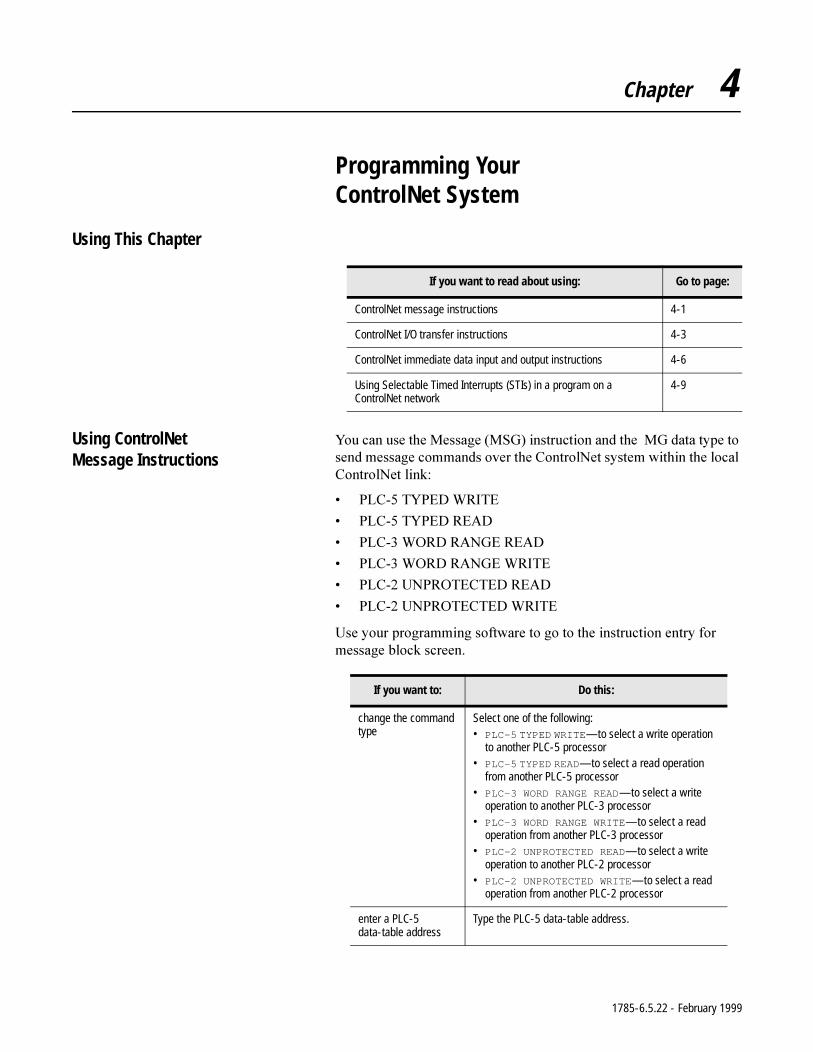
Chapter 4
Programming Your ControlNet System
Using This Chapter
Using ControlNetMessage Instructions
<RXFDQXVHWKH0HVVDJH06*LQVWUXFWLRQDQGWKH0*GDWDW\SHWRVHQGPHVVDJHFRPPDQGVRYHUWKH&RQWURO1HWV\VWHPZLWKLQWKHORFDO&RQWURO1HWOLQN
3/&7<3(':5,7(
3/&7<3('5($'
3/&:25'5$1*(5($'
3/&:25'5$1*(:5,7(
3/&813527(&7('5($'
3/&813527(&7(':5,7(
8VH\RXUSURJUDPPLQJVRIWZDUHWRJRWRWKHLQVWUXFWLRQHQWU\IRUPHVVDJHEORFNVFUHHQ
If you want to read about using: Go to page:
ControlNet message instructions 4-1
ControlNet I/O transfer instructions 4-3
ControlNet immediate data input and output instructions 4-6
Using Selectable Timed Interrupts (STIs) in a program on a ControlNet network
4-9
If you want to: Do this:
change the command type
Select one of the following:• PLC-5 TYPED WRITE—to select a write operation
to another PLC-5 processor• PLC-5 TYPED READ—to select a read operation
from another PLC-5 processor• PLC-3 WORD RANGE READ—to select a write
operation to another PLC-3 processor• PLC-3 WORD RANGE WRITE—to select a read
operation from another PLC-3 processor• PLC-2 UNPROTECTED READ—to select a write
operation to another PLC-2 processor• PLC-2 UNPROTECTED WRITE—to select a read
operation from another PLC-2 processor
enter a PLC-5 data-table address
Type the PLC-5 data-table address.
1785-6.5.22 - February 1999
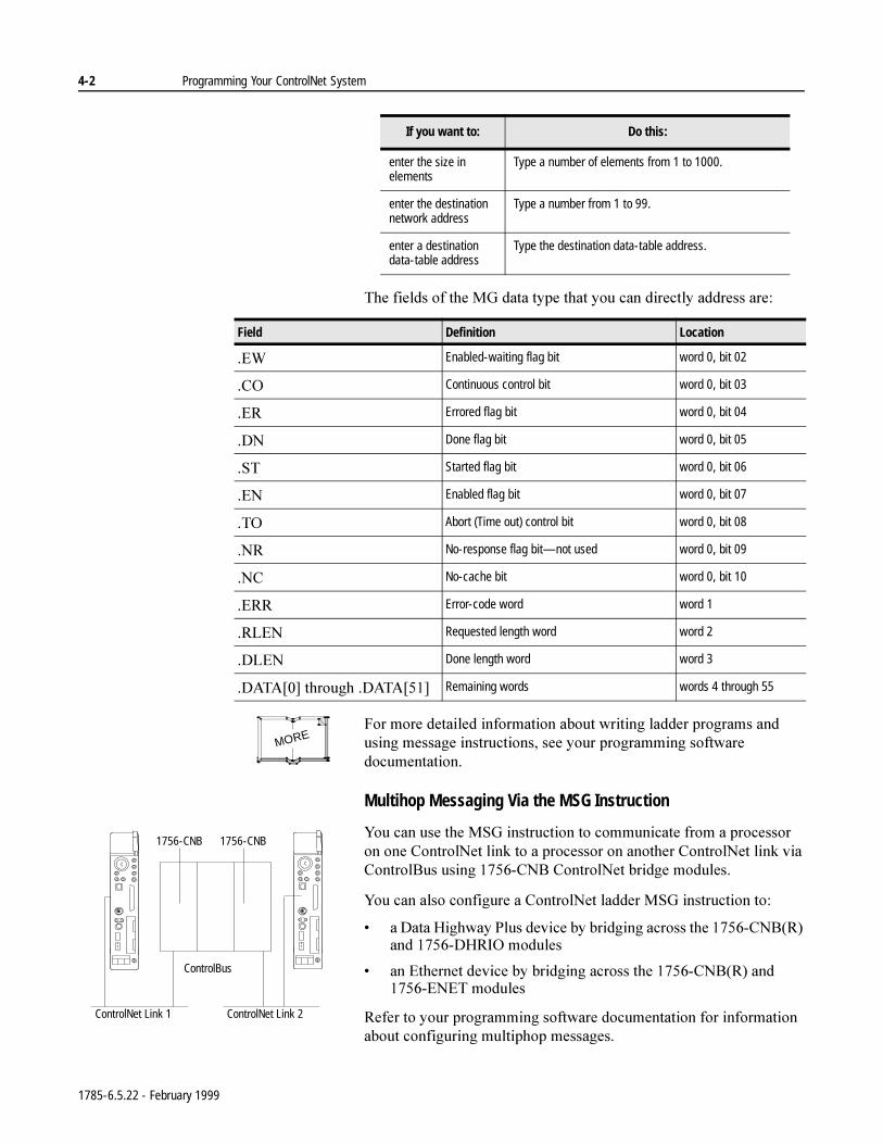
4-2 Programming Your ControlNet System
7KHILHOGVRIWKH0*GDWDW\SHWKDW\RXFDQGLUHFWO\DGGUHVVDUH
)RUPRUHGHWDLOHGLQIRUPDWLRQDERXWZULWLQJODGGHUSURJUDPVDQGXVLQJPHVVDJHLQVWUXFWLRQVVHH\RXUSURJUDPPLQJVRIWZDUHGRFXPHQWDWLRQ
Multihop Messaging Via the MSG Instruction
<RXFDQXVHWKH06*LQVWUXFWLRQWRFRPPXQLFDWHIURPDSURFHVVRURQRQH&RQWURO1HWOLQNWRDSURFHVVRURQDQRWKHU&RQWURO1HWOLQNYLD&RQWURO%XVXVLQJ&1%&RQWURO1HWEULGJHPRGXOHV
<RXFDQDOVRFRQILJXUHD&RQWURO1HWODGGHU06*LQVWUXFWLRQWR
D'DWD+LJKZD\3OXVGHYLFHE\EULGJLQJDFURVVWKH&1%5DQG'+5,2PRGXOHV
DQ(WKHUQHWGHYLFHE\EULGJLQJDFURVVWKH&1%5DQG(1(7PRGXOHV
5HIHUWR\RXUSURJUDPPLQJVRIWZDUHGRFXPHQWDWLRQIRULQIRUPDWLRQDERXWFRQILJXULQJPXOWLSKRSPHVVDJHV
enter the size in elements
Type a number of elements from 1 to 1000.
enter the destination network address
Type a number from 1 to 99.
enter a destination data-table address
Type the destination data-table address.
If you want to: Do this:
Field Definition Location
(: Enabled-waiting flag bit word 0, bit 02
&2 Continuous control bit word 0, bit 03
(5 Errored flag bit word 0, bit 04
'1 Done flag bit word 0, bit 05
67 Started flag bit word 0, bit 06
(1 Enabled flag bit word 0, bit 07
72 Abort (Time out) control bit word 0, bit 08
15 No-response flag bit—not used word 0, bit 09
1& No-cache bit word 0, bit 10
(55 Error-code word word 1
5/(1 Requested length word word 2
'/(1 Done length word word 3
'$7$>@WKURXJK'$7$>@ Remaining words words 4 through 55
MORE
ControlNet Link 1 ControlNet Link 2
1756-CNB 1756-CNB
ControlBus
1785-6.5.22 - February 1999
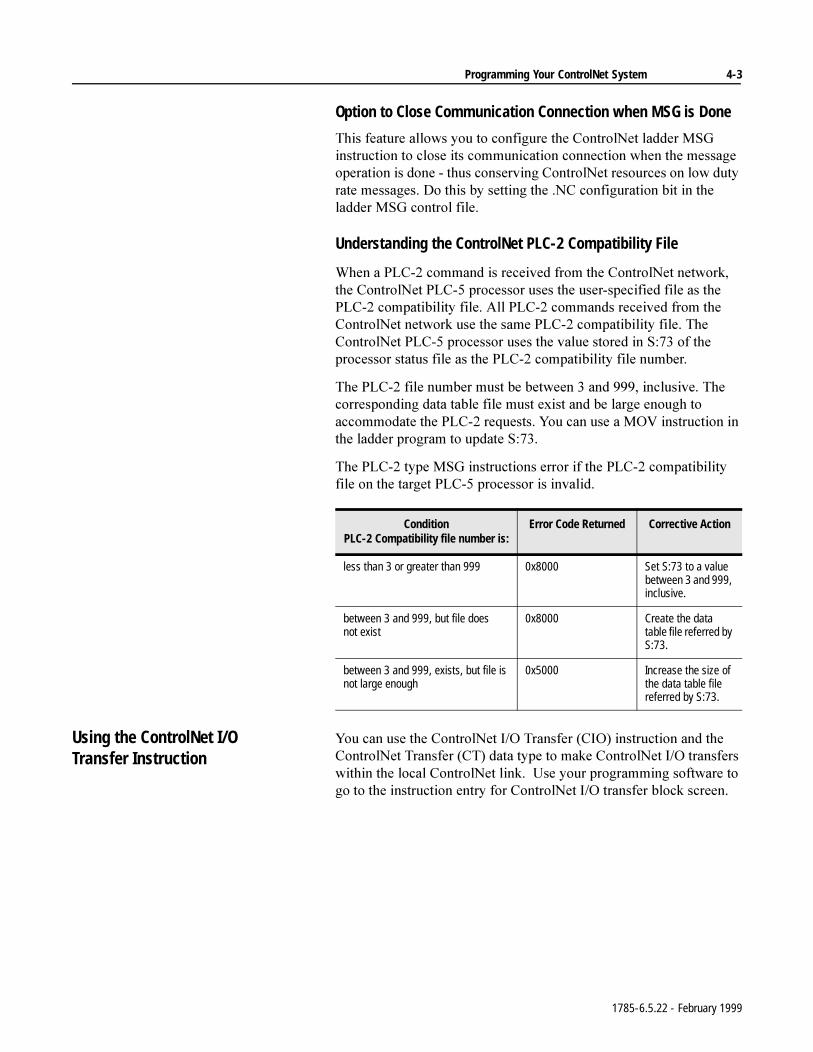
Programming Your ControlNet System 4-3
Option to Close Communication Connection when MSG is Done
7KLVIHDWXUHDOORZV\RXWRFRQILJXUHWKH&RQWURO1HWODGGHU06*LQVWUXFWLRQWRFORVHLWVFRPPXQLFDWLRQFRQQHFWLRQZKHQWKHPHVVDJHRSHUDWLRQLVGRQHWKXVFRQVHUYLQJ&RQWURO1HWUHVRXUFHVRQORZGXW\UDWHPHVVDJHV'RWKLVE\VHWWLQJWKH1&FRQILJXUDWLRQELWLQWKHODGGHU06*FRQWUROILOH
Understanding the ControlNet PLC-2 Compatibility File
:KHQD3/&FRPPDQGLVUHFHLYHGIURPWKH&RQWURO1HWQHWZRUNWKH&RQWURO1HW3/&SURFHVVRUXVHVWKHXVHUVSHFLILHGILOHDVWKH3/&FRPSDWLELOLW\ILOH$OO3/&FRPPDQGVUHFHLYHGIURPWKH&RQWURO1HWQHWZRUNXVHWKHVDPH3/&FRPSDWLELOLW\ILOH7KH&RQWURO1HW3/&SURFHVVRUXVHVWKHYDOXHVWRUHGLQ6RIWKHSURFHVVRUVWDWXVILOHDVWKH3/&FRPSDWLELOLW\ILOHQXPEHU
7KH3/&ILOHQXPEHUPXVWEHEHWZHHQDQGLQFOXVLYH7KHFRUUHVSRQGLQJGDWDWDEOHILOHPXVWH[LVWDQGEHODUJHHQRXJKWRDFFRPPRGDWHWKH3/&UHTXHVWV<RXFDQXVHD029LQVWUXFWLRQLQWKHODGGHUSURJUDPWRXSGDWH6
7KH3/&W\SH06*LQVWUXFWLRQVHUURULIWKH3/&FRPSDWLELOLW\ILOHRQWKHWDUJHW3/&SURFHVVRULVLQYDOLG
Using the ControlNet I/OTransfer Instruction
<RXFDQXVHWKH&RQWURO1HW,27UDQVIHU&,2LQVWUXFWLRQDQGWKH&RQWURO1HW7UDQVIHU&7GDWDW\SHWRPDNH&RQWURO1HW,2WUDQVIHUVZLWKLQWKHORFDO&RQWURO1HWOLQN8VH\RXUSURJUDPPLQJVRIWZDUHWRJRWRWKHLQVWUXFWLRQHQWU\IRU&RQWURO1HW,2WUDQVIHUEORFNVFUHHQ
ConditionPLC-2 Compatibility file number is:
Error Code Returned Corrective Action
less than 3 or greater than 999 0x8000 Set S:73 to a value between 3 and 999, inclusive.
between 3 and 999, but file does not exist
0x8000 Create the data table file referred by S:73.
between 3 and 999, exists, but file is not large enough
0x5000 Increase the size of the data table file referred by S:73.
1785-6.5.22 - February 1999
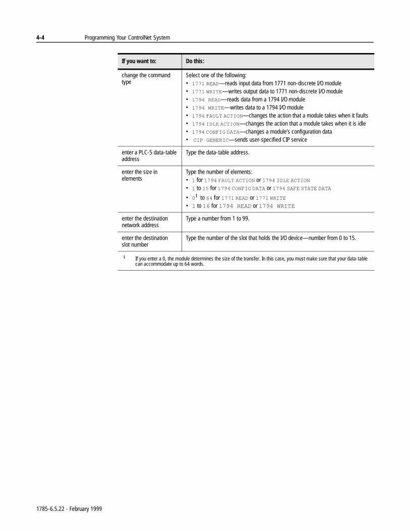
4-4 Programming Your ControlNet System
If you want to: Do this:
change the command type
Select one of the following:• 1771 READ—reads input data from 1771 non-discrete I/O module• 1771 WRITE—writes output data to 1771 non-discrete I/O module• 1794 READ—reads data from a 1794 I/O module• 1794 WRITE—writes data to a 1794 I/O module• 1794 FAULT ACTION—changes the action that a module takes when it faults• 1794 IDLE ACTION—changes the action that a module takes when it is idle • 1794 CONFIG DATA—changes a module’s configuration data• CIP GENERIC—sends user-specified CIP service
enter a PLC-5 data-table address
Type the data-table address.
enter the size in elements
Type the number of elements:• 1 for 1794 FAULT ACTION or 1794 IDLE ACTION
• 1 to 15 for 1794 CONFIG DATA or 1794 SAFE STATE DATA
• 0 to 64 for 1771 READ or 1771 WRITE
• 1 to 16 for 1794 READ or 1794 WRITE
enter the destination network address
Type a number from 1 to 99.
enter the destination slot number
Type the number of the slot that holds the I/O device—number from 0 to 15.
If you enter a 0, the module determines the size of the transfer. In this case, you must make sure that your data-table can accommodate up to 64 words.
1785-6.5.22 - February 1999
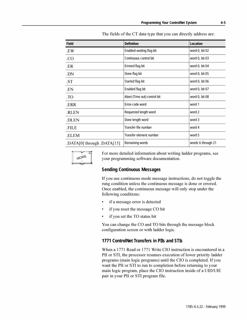
Programming Your ControlNet System 4-5
7KHILHOGVRIWKH&7GDWDW\SHWKDW\RXFDQGLUHFWO\DGGUHVVDUH
)RUPRUHGHWDLOHGLQIRUPDWLRQDERXWZULWLQJODGGHUSURJUDPVVHH\RXUSURJUDPPLQJVRIWZDUHGRFXPHQWDWLRQ
Sending Continuous Messages
,I\RXXVHFRQWLQXRXVPRGHPHVVDJHLQVWUXFWLRQVGRQRWWRJJOHWKHUXQJFRQGLWLRQXQOHVVWKHFRQWLQXRXVPHVVDJHLVGRQHRUHUURUHG2QFHHQDEOHGWKHFRQWLQXRXVPHVVDJHZLOORQO\VWRSXQGHUWKHIROORZLQJFRQGLWLRQV
LIDPHVVDJHHUURULVGHWHFWHG
LI\RXUHVHWWKHPHVVDJH&2ELW
LI\RXVHWWKH72VWDWXVELW
<RXFDQFKDQJHWKH&2DQG72ELWVWKURXJKWKHPHVVDJHEORFNFRQILJXUDWLRQVFUHHQRUZLWKODGGHUORJLF
1771 ControlNet Transfers in PIIs and STIs
:KHQD5HDGRU:ULWH&,2LQVWUXFWLRQLVHQFRXQWHUHGLQD3,,RU67,WKHSURFHVVRUUHVXPHVH[HFXWLRQRIORZHUSULRULW\ODGGHUSURJUDPVPDLQORJLFSURJUDPVXQWLOWKH&,2LVFRPSOHWHG,I\RXZDQWWKH3,,RU67,WRUXQWRFRPSOHWLRQEHIRUHUHWXUQLQJWR\RXUPDLQORJLFSURJUDPSODFHWKH&,2LQVWUXFWLRQLQVLGHRID8,'8,(SDLULQ\RXU3,,RU67,SURJUDPILOH
Field Definition Location
(: Enabled-waiting flag bit word 0, bit 02
&2 Continuous control bit word 0, bit 03
(5 Errored flag bit word 0, bit 04
'1 Done flag bit word 0, bit 05
67 Started flag bit word 0, bit 06
(1 Enabled flag bit word 0, bit 07
72 Abort (Time out) control bit word 0, bit 08
(55 Error-code word word 1
5/(1 Requested length word word 2
'/(1 Done length word word 3
),/( Transfer file number word 4
(/(0 Transfer element number word 5
'$7$>@WKURXJK'$7$>@ Remaining words words 6 through 21
MORE
1785-6.5.22 - February 1999
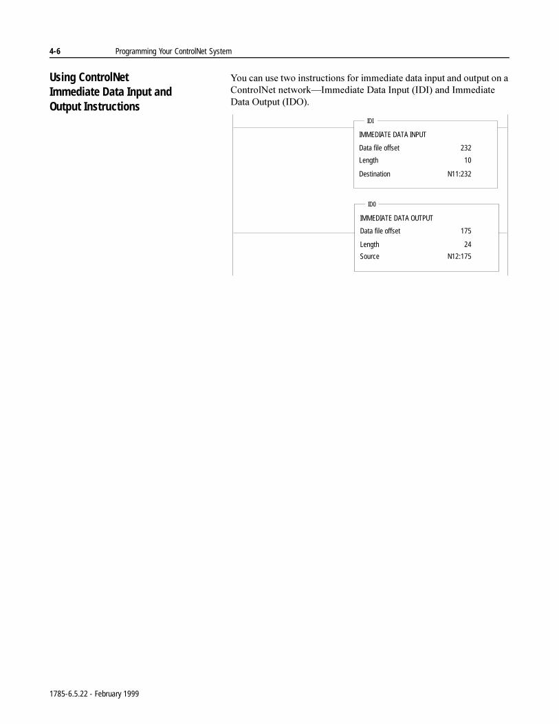
4-6 Programming Your ControlNet System
Using ControlNetImmediate Data Input andOutput Instructions
<RXFDQXVHWZRLQVWUXFWLRQVIRULPPHGLDWHGDWDLQSXWDQGRXWSXWRQD&RQWURO1HWQHWZRUN²,PPHGLDWH'DWD,QSXW,',DQG,PPHGLDWH'DWD2XWSXW,'2
IMMEDIATE DATA INPUT
Data file offset
Length
Destination
IDI
IMMEDIATE DATA OUTPUT
Data file offset
Length
Source
ID0
232
10
N11:232
175
24
N12:175
1785-6.5.22 - February 1999
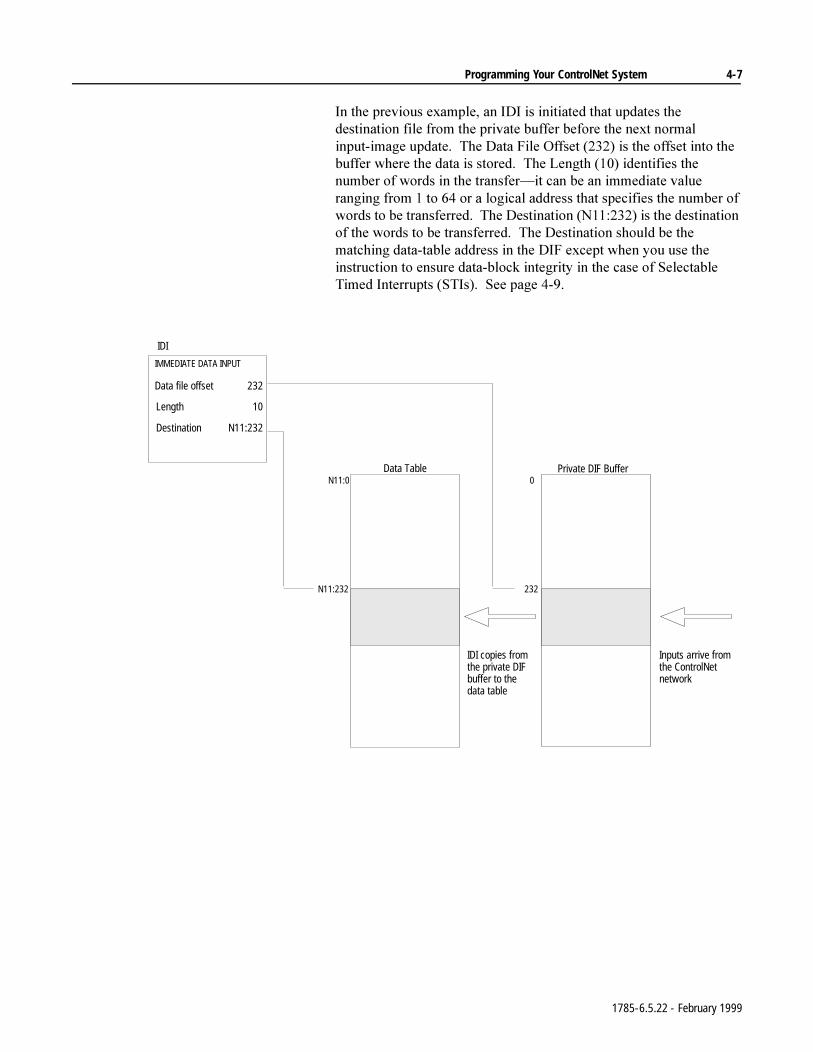
Programming Your ControlNet System 4-7
,QWKHSUHYLRXVH[DPSOHDQ,',LVLQLWLDWHGWKDWXSGDWHVWKHGHVWLQDWLRQILOHIURPWKHSULYDWHEXIIHUEHIRUHWKHQH[WQRUPDOLQSXWLPDJHXSGDWH7KH'DWD)LOH2IIVHWLVWKHRIIVHWLQWRWKHEXIIHUZKHUHWKHGDWDLVVWRUHG7KH/HQJWKLGHQWLILHVWKHQXPEHURIZRUGVLQWKHWUDQVIHU²LWFDQEHDQLPPHGLDWHYDOXHUDQJLQJIURPWRRUDORJLFDODGGUHVVWKDWVSHFLILHVWKHQXPEHURIZRUGVWREHWUDQVIHUUHG7KH'HVWLQDWLRQ1LVWKHGHVWLQDWLRQRIWKHZRUGVWREHWUDQVIHUUHG7KH'HVWLQDWLRQVKRXOGEHWKHPDWFKLQJGDWDWDEOHDGGUHVVLQWKH',)H[FHSWZKHQ\RXXVHWKHLQVWUXFWLRQWRHQVXUHGDWDEORFNLQWHJULW\LQWKHFDVHRI6HOHFWDEOH7LPHG,QWHUUXSWV67,V6HHSDJH
IDI
IMMEDIATE DATA INPUT
Data file offset
Length
Destination
IDI copies from the private DIF buffer to the data table
Inputs arrive from the ControlNet network
N11:232 232
N11:0 0Data Table Private DIF Buffer
232
10
N11:232
1785-6.5.22 - February 1999
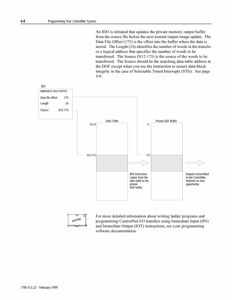
4-8 Programming Your ControlNet System
$Q,'2LVLQLWLDWHGWKDWXSGDWHVWKHSULYDWHPHPRU\RXWSXWEXIIHUIURPWKHVRXUFHILOHEHIRUHWKHQH[WQRUPDORXWSXWLPDJHXSGDWH7KH'DWD)LOH2IIVHWLVWKHRIIVHWLQWRWKHEXIIHUZKHUHWKHGDWDLVVWRUHG7KH/HQJWKLGHQWLILHVWKHQXPEHURIZRUGVLQWKHWUDQVIHURUDORJLFDODGGUHVVWKDWVSHFLILHVWKHQXPEHURIZRUGVWREHWUDQVIHUUHG7KH6RXUFH1LVWKHVRXUFHRIWKHZRUGVWREHWUDQVIHUUHG7KH6RXUFHVKRXOGEHWKHPDWFKLQJGDWDWDEOHDGGUHVVLQWKH'2)H[FHSWZKHQ\RXXVHWKHLQVWUXFWLRQWRHQVXUHGDWDEORFNLQWHJULW\LQWKHFDVHRI6HOHFWDEOH7LPHG,QWHUUXSWV67,V6HHSDJH
)RUPRUHGHWDLOHGLQIRUPDWLRQDERXWZULWLQJODGGHUSURJUDPVDQGSURJUDPPLQJ&RQWURO1HW,2WUDQVIHUVXVLQJ,PPHGLDWH,QSXW,,1DQG,PPHGLDWH2XWSXW,27LQVWUXFWLRQVVHH\RXUSURJUDPPLQJVRIWZDUHGRFXPHQWDWLRQ
IDO
IMMEDIATE DATA OUTPUT
Data file offset
Length
Source
IDO instruction copies from the data table to the private DOF buffer
Outputs transmitted to the ControlNet network on next opportunity
N12:175 175
N12:0 0Data Table Private DOF Buffer
175
24
N12:175
MORE
1785-6.5.22 - February 1999
Programming Your ControlNet System 4-9
Using Selectable TimedInterrupts with a Programon a ControlNet Network
<RXPXVWEHFDUHIXOZKHQXVLQJ6HOHFWDEOH7LPHG,QWHUUXSWV67,VZLWKDSURJUDPRQD&RQWURO1HWQHWZRUN
$6HOHFWDEOH7LPHG,QWHUUXSW67,SHULRGLFDOO\LQWHUUXSWVSULPDU\SURJUDPH[HFXWLRQLQRUGHUWRUXQDVXESURJUDPWRFRPSOHWLRQ,IDQ67,RFFXUVZKLOHDQRUPDO&RQWURO1HWQRQGLVFUHWH,2GDWDWUDQVIHURUD&RQWURO1HW,PPHGLDWH'DWD,2LQVWUXFWLRQ,'2RU,',LVLQSURJUHVVDQGWKH\ERWKRSHUDWHRQWKHVDPHVHWRIGDWDWKHLQWHJULW\RIWKDWEORFNRIGDWDLVMHRSDUGL]HG
7RHQVXUHGDWDEORFNLQWHJULW\ZULWH\RXU67,URXWLQHVRWKDWLWRSHUDWHVRQLWVRZQFRS\RIWKHGDWDEORFNWKDWLWQHHGV8VH&RQWURO1HW,PPHGLDWH'DWD,2LQVWUXFWLRQV,'2DQG,',ZLWKLQ\RXU67,WRFRS\WKHQHHGHGEORFNRIGDWDRXWWRDQGEDFNIURPDWHPSRUDU\ORFDWLRQWKDWLVGLIIHUHQWIURPWKDWXVHGE\WKHQRUPDOGDWDWDEOH
)RUGHWDLOHGLQIRUPDWLRQDERXW67,VVHH\RXUSURJUDPPLQJVRIWZDUHGRFXPHQWDWLRQMORE
1785-6.5.22 - February 1999
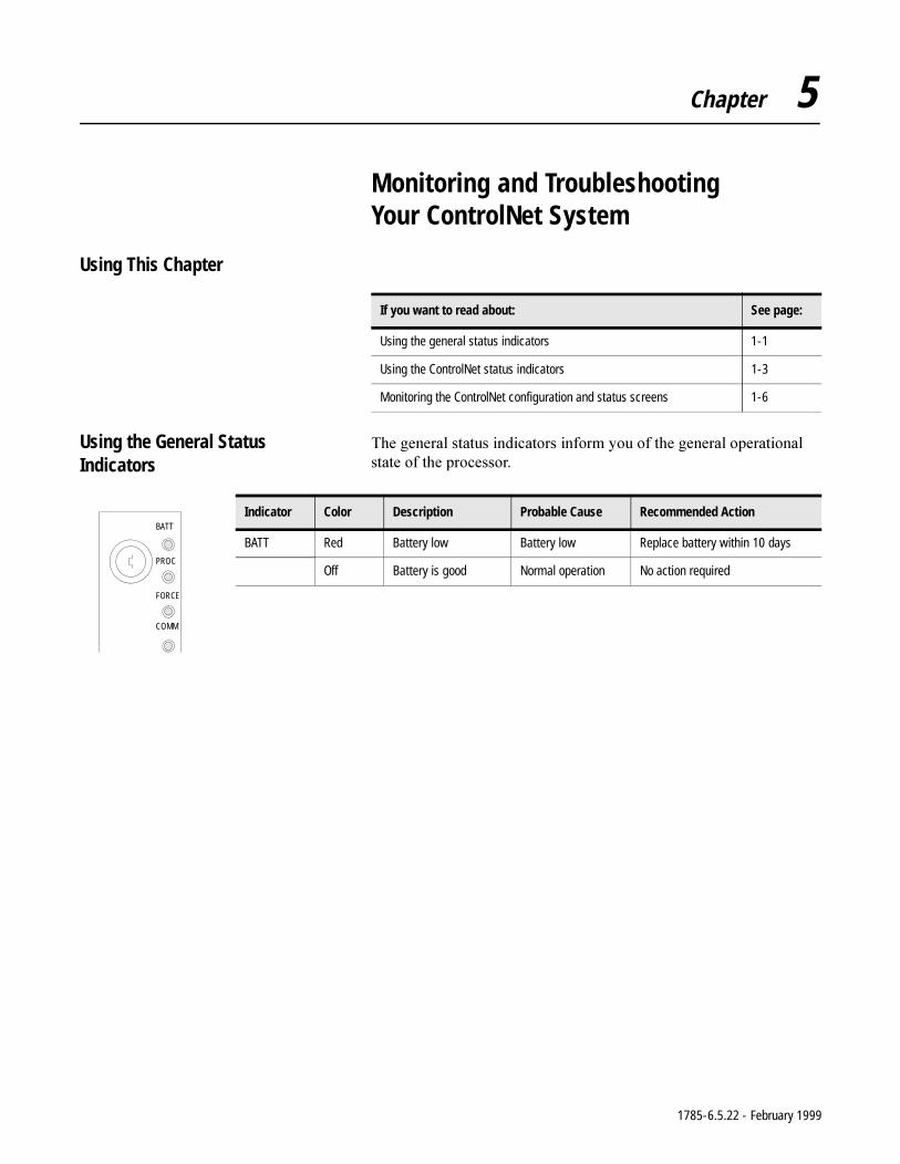
Chapter 5
Monitoring and Troubleshooting Your ControlNet System
Using This Chapter
Using the General Status Indicators
7KHJHQHUDOVWDWXVLQGLFDWRUVLQIRUP\RXRIWKHJHQHUDORSHUDWLRQDOVWDWHRIWKHSURFHVVRU
If you want to read about: See page:
Using the general status indicators 1-1
Using the ControlNet status indicators 1-3
Monitoring the ControlNet configuration and status screens 1-6
Indicator Color Description Probable Cause Recommended Action
BATT Red Battery low Battery low Replace battery within 10 days
Off Battery is good Normal operation No action required
BATT
PROC
FORCE
COMM
1785-6.5.22 - February 1999
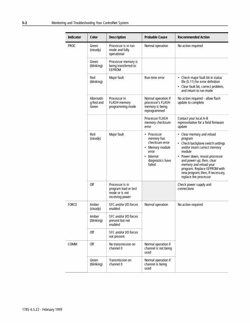
5-2 Monitoring and Troubleshooting Your ControlNet System
PROC Green (steady)
Processor is in run mode and fully operational
Normal operation No action required
Green (blinking)
Processor memory is being transferred to EEPROM
Red (blinking)
Major fault Run-time error • Check major fault bit in status file (S:11) for error definition
• Clear fault bit, correct problem, and return to run mode
Alternating Red and Green
Processor in FLASH-memory programming mode
Normal operation if processor's FLASH memory is being reprogrammed
No action required - allow flash update to complete
Processor FLASH memory checksum error
Contact your local A-B representative for a field firmware update
Red (steady)
Major fault • Processor memory has checksum error
• Memory module error
• Internal diagnostics have failed
• Clear memory and reload program
• Check backplane switch settings and/or insert correct memory module
• Power down, reseat processor and power up; then, clear memory and reload your program. Replace EEPROM with new program; then, if necessary, replace the processor
Off Processor is in program load or test mode or is not receiving power
Check power supply and connections
FORCE Amber (steady)
SFC and/or I/O forces enabled
Normal operation No action required
Amber (blinking)
SFC and/or I/O forces present but not enabled
Off SFC and/or I/O forces not present
COMM Off No transmission on channel 0
Normal operation if channel is not being used
Green (blinking)
Transmission on channel 0
Normal operation if channel is being used
Indicator Color Description Probable Cause Recommended Action
1785-6.5.22 - February 1999
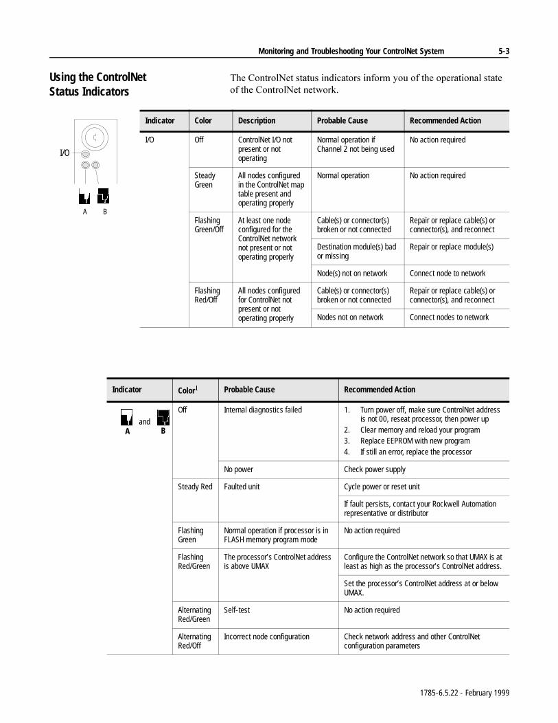
Monitoring and Troubleshooting Your ControlNet System 5-3
Using the ControlNetStatus Indicators
7KH&RQWURO1HWVWDWXVLQGLFDWRUVLQIRUP\RXRIWKHRSHUDWLRQDOVWDWHRIWKH&RQWURO1HWQHWZRUN
Indicator Color Description Probable Cause Recommended Action
I/O Off ControlNet I/O not present or not operating
Normal operation if Channel 2 not being used
No action required
Steady Green
All nodes configured in the ControlNet map table present and operating properly
Normal operation No action required
Flashing Green/Off
At least one node configured for the ControlNet network not present or not operating properly
Cable(s) or connector(s) broken or not connected
Repair or replace cable(s) or connector(s), and reconnect
Destination module(s) bad or missing
Repair or replace module(s)
Node(s) not on network Connect node to network
Flashing Red/Off
All nodes configured for ControlNet not present or not operating properly
Cable(s) or connector(s) broken or not connected
Repair or replace cable(s) or connector(s), and reconnect
Nodes not on network Connect nodes to network
I/O
A B
Indicator Color Probable Cause Recommended Action
Off Internal diagnostics failed 1. Turn power off, make sure ControlNet address is not 00, reseat processor, then power up
2. Clear memory and reload your program3. Replace EEPROM with new program4. If still an error, replace the processor
No power Check power supply
Steady Red Faulted unit Cycle power or reset unit
If fault persists, contact your Rockwell Automation representative or distributor
Flashing Green
Normal operation if processor is in FLASH memory program mode
No action required
Flashing Red/Green
The processor’s ControlNet address is above UMAX
Configure the ControlNet network so that UMAX is at least as high as the processor’s ControlNet address.
Set the processor’s ControlNet address at or below UMAX.
Alternating Red/Green
Self-test No action required
Alternating Red/Off
Incorrect node configuration Check network address and other ControlNet configuration parameters
andA B
1785-6.5.22 - February 1999
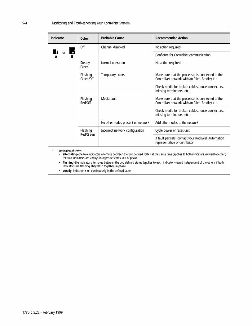
5-4 Monitoring and Troubleshooting Your ControlNet System
Indicator Color Probable Cause Recommended Action
Off Channel disabled No action required
Configure for ControlNet communication
Steady Green
Normal operation No action required
Flashing Green/Off
Temporary errors Make sure that the processor is connected to the ControlNet network with an Allen-Bradley tap.
Check media for broken cables, loose connectors, missing terminators, etc.
Flashing Red/Off
Media fault Make sure that the processor is connected to the ControlNet network with an Allen-Bradley tap.
Check media for broken cables, loose connectors, missing terminators, etc.
No other nodes present on network Add other nodes to the network
Flashing Red/Green
Incorrect network configuration Cycle power or reset unit
If fault persists, contact your Rockwell Automation representative or distributor
Definition of terms:• alternating–the two indicators alternate between the two defined states at the same time (applies to both indicators viewed together);
the two indicators are always in opposite states, out of phase• flashing–the indicator alternates between the two defined states (applies to each indicator viewed independent of the other); if both
indicators are flashing, they flash together, in phase• steady–indicator is on continuously in the defined state
orA B
1785-6.5.22 - February 1999
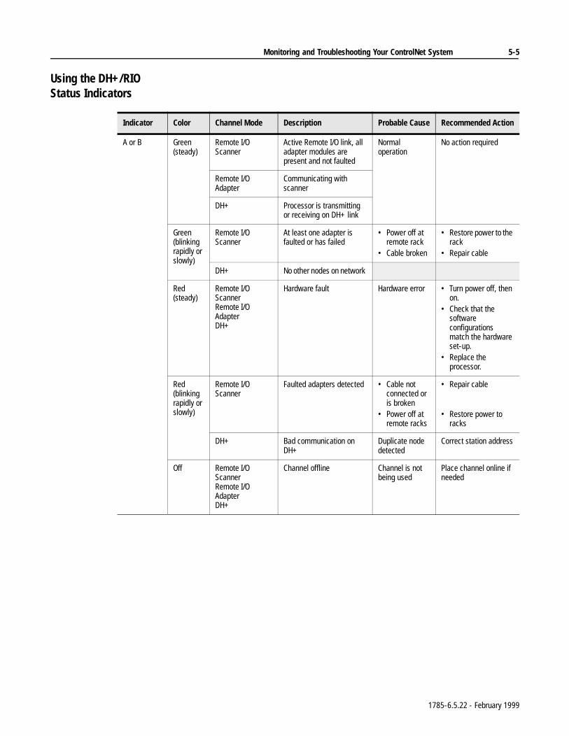
Monitoring and Troubleshooting Your ControlNet System 5-5
Using the DH+/RIOStatus Indicators
Indicator Color Channel Mode Description Probable Cause Recommended Action
A or B Green(steady)
Remote I/O Scanner
Active Remote I/O link, all adapter modules are present and not faulted
Normal operation
No action required
Remote I/O Adapter
Communicating with scanner
DH+ Processor is transmitting or receiving on DH+ link
Green (blinking rapidly or slowly)
Remote I/O Scanner
At least one adapter is faulted or has failed
• Power off at remote rack
• Cable broken
• Restore power to the rack
• Repair cable
DH+ No other nodes on network
Red(steady)
Remote I/O ScannerRemote I/O AdapterDH+
Hardware fault Hardware error • Turn power off, then on.
• Check that the software configurations match the hardware set-up.
• Replace the processor.
Red(blinking rapidly or slowly)
Remote I/O Scanner
Faulted adapters detected • Cable not connected or is broken
• Power off at remote racks
• Repair cable
• Restore power to racks
DH+ Bad communication on DH+
Duplicate node detected
Correct station address
Off Remote I/O ScannerRemote I/O AdapterDH+
Channel offline Channel is not being used
Place channel online if needed
1785-6.5.22 - February 1999
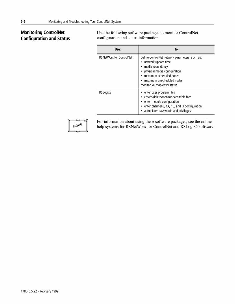
5-6 Monitoring and Troubleshooting Your ControlNet System
Monitoring ControlNetConfiguration and Status
8VHWKHIROORZLQJVRIWZDUHSDFNDJHVWRPRQLWRU&RQWURO1HWFRQILJXUDWLRQDQGVWDWXVLQIRUPDWLRQ
)RULQIRUPDWLRQDERXWXVLQJWKHVHVRIWZDUHSDFNDJHVVHHWKHRQOLQHKHOSV\VWHPVIRU561HW:RU[IRU&RQWURO1HWDQG56/RJL[VRIWZDUH
Use: To:
RSNetWorx for ControlNet define ControlNet network parameters, such as:• network update time• media redundancy• physical media configuration• maximum scheduled nodes• maximum unscheduled nodesmonitor I/O map entry status
RSLogix5 • enter user program files• create/delete/monitor data table files• enter module configuration• enter channel 0, 1A, 1B, and, 3 configuration• administer passwords and privileges
MORE
1785-6.5.22 - February 1999
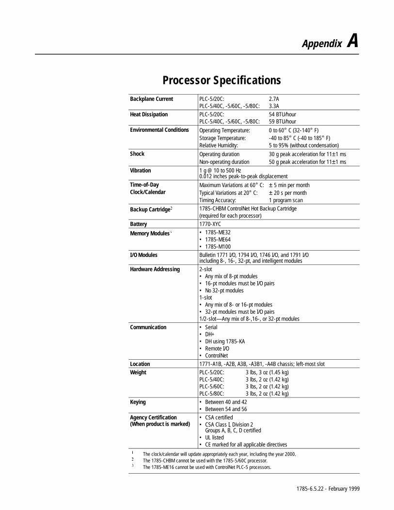
Appendix A
Processor Specifications Backplane Current PLC-5/20C: 2.7A
PLC-5/40C, -5/60C, -5/80C: 3.3A
Heat Dissipation PLC-5/20C: 54 BTU/hourPLC-5/40C, -5/60C, -5/80C: 59 BTU/hour
Environmental Conditions Operating Temperature: 0 to 60° C (32-140° F)Storage Temperature: -40 to 85° C (-40 to 185° F)Relative Humidity: 5 to 95% (without condensation)
Shock Operating duration 30 g peak acceleration for 11±1 ms Non-operating duration 50 g peak acceleration for 11±1 ms
Vibration 1 g @ 10 to 500 Hz0.012 inches peak-to-peak displacement
Time-of-Day Clock/Calendar
Maximum Variations at 60° C: ± 5 min per monthTypical Variations at 20° C: ± 20 s per monthTiming Accuracy: 1 program scan
Backup Cartridge 1785-CHBM ControlNet Hot Backup Cartridge(required for each processor)
Battery 1770-XYC
Memory Modules • 1785-ME32• 1785-ME64• 1785-M100
I/O Modules Bulletin 1771 I/O, 1794 I/O, 1746 I/O, and 1791 I/O including 8-, 16-, 32-pt, and intelligent modules
Hardware Addressing 2-slot• Any mix of 8-pt modules• 16-pt modules must be I/O pairs• No 32-pt modules1-slot• Any mix of 8- or 16-pt modules• 32-pt modules must be I/O pairs1/2-slot—Any mix of 8-,16-, or 32-pt modules
Communication • Serial• DH+• DH using 1785-KA• Remote I/O• ControlNet
Location 1771-A1B, -A2B, A3B, -A3B1, -A4B chassis; left-most slot
Weight PLC-5/20C: 3 lbs, 3 oz (1.45 kg)PLC-5/40C: 3 lbs, 2 oz (1.42 kg)PLC-5/60C: 3 lbs, 2 oz (1.42 kg)PLC-5/80C: 3 lbs, 2 oz (1.42 kg)
Keying • Between 40 and 42• Between 54 and 56
Agency Certification(When product is marked)
• CSA certified• CSA Class I, Division 2
Groups A, B, C, D certified• UL listed• CE marked for all applicable directives
The clock/calendar will update appropriately each year, including the year 2000. The 1785-CHBM cannot be used with the 1785-5/60C processor. The 1785-ME16 cannot be used with ControlNet PLC-5 processors.
1785-6.5.22 - February 1999
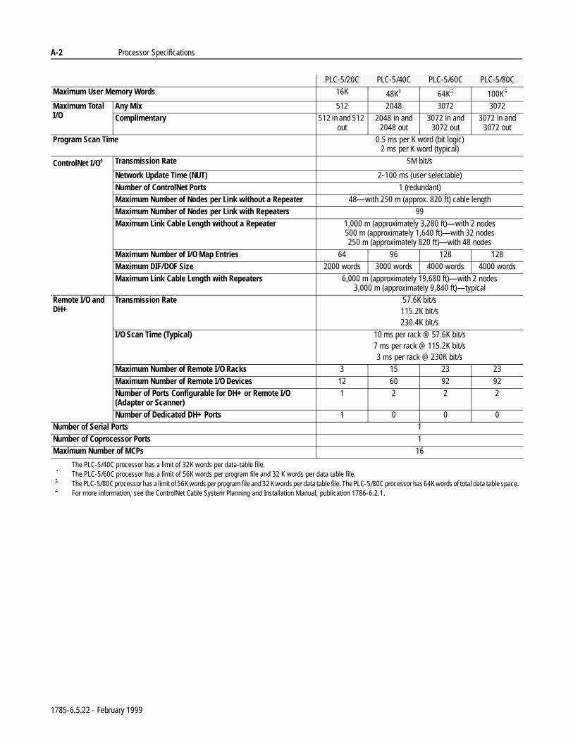
A-2 Processor Specifications
PLC-5/20C PLC-5/40C PLC-5/60C PLC-5/80CMaximum User Memory Words 16K 48K 64K 100K
Maximum Total I/O
Any Mix 512 2048 3072 3072Complimentary 512 in and 512
out2048 in and
2048 out3072 in and
3072 out3072 in and
3072 outProgram Scan Time 0.5 ms per K word (bit logic)
2 ms per K word (typical)
ControlNet I/O Transmission Rate 5M bit/s
Network Update Time (NUT) 2-100 ms (user selectable)
Number of ControlNet Ports 1 (redundant)Maximum Number of Nodes per Link without a Repeater 48—with 250 m (approx. 820 ft) cable lengthMaximum Number of Nodes per Link with Repeaters 99
Maximum Link Cable Length without a Repeater 1,000 m (approximately 3,280 ft)—with 2 nodes500 m (approximately 1,640 ft)—with 32 nodes250 m (approximately 820 ft)—with 48 nodes
Maximum Number of I/O Map Entries 64 96 128 128Maximum DIF/DOF Size 2000 words 3000 words 4000 words 4000 words
Maximum Link Cable Length with Repeaters 6,000 m (approximately 19,680 ft)—with 2 nodes3,000 m (approximately 9,840 ft)—typical
Remote I/O and DH+
Transmission Rate 57.6K bit/s115.2K bit/s230.4K bit/s
I/O Scan Time (Typical) 10 ms per rack @ 57.6K bit/s7 ms per rack @ 115.2K bit/s3 ms per rack @ 230K bit/s
Maximum Number of Remote I/O Racks 3 15 23 23
Maximum Number of Remote I/O Devices 12 60 92 92Number of Ports Configurable for DH+ or Remote I/O (Adapter or Scanner)
1 2 2 2
Number of Dedicated DH+ Ports 1 0 0 0Number of Serial Ports 1
Number of Coprocessor Ports 1Maximum Number of MCPs 16 The PLC-5/40C processor has a limit of 32K words per data-table file. The PLC-5/60C processor has a limit of 56K words per program file and 32 K words per data table file. The PLC-5/80C processor has a limit of 56K words per program file and 32 K words per data table file. The PLC-5/80C processor has 64K words of total data table space. For more information, see the ControlNet Cable System Planning and Installation Manual, publication 1786-6.2.1.
1785-6.5.22 - February 1999
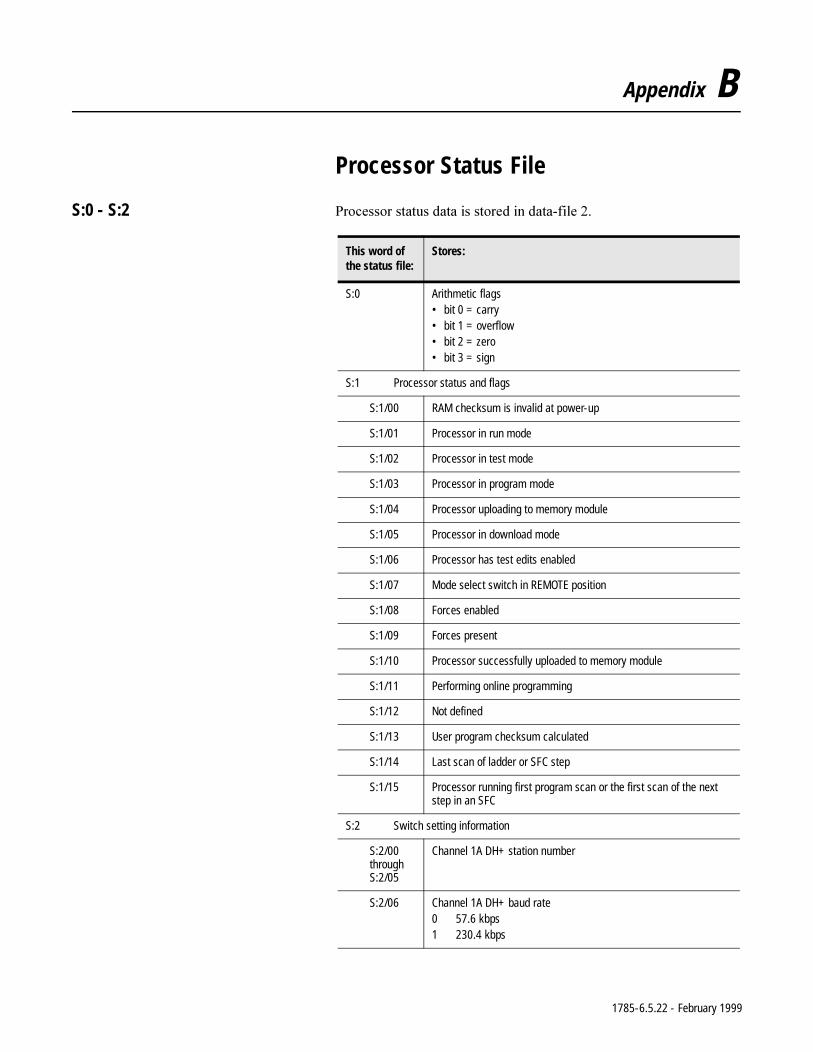
Appendix B
Processor Status File
S:0 - S:2 3URFHVVRUVWDWXVGDWDLVVWRUHGLQGDWDILOH
This word ofthe status file:
Stores:
S:0 Arithmetic flags• bit 0 = carry• bit 1 = overflow• bit 2 = zero• bit 3 = sign
S:1 Processor status and flags
S:1/00 RAM checksum is invalid at power-up
S:1/01 Processor in run mode
S:1/02 Processor in test mode
S:1/03 Processor in program mode
S:1/04 Processor uploading to memory module
S:1/05 Processor in download mode
S:1/06 Processor has test edits enabled
S:1/07 Mode select switch in REMOTE position
S:1/08 Forces enabled
S:1/09 Forces present
S:1/10 Processor successfully uploaded to memory module
S:1/11 Performing online programming
S:1/12 Not defined
S:1/13 User program checksum calculated
S:1/14 Last scan of ladder or SFC step
S:1/15 Processor running first program scan or the first scan of the next step in an SFC
S:2 Switch setting information
S:2/00throughS:2/05
Channel 1A DH+ station number
S:2/06 Channel 1A DH+ baud rate0 57.6 kbps1 230.4 kbps
1785-6.5.22 - February 1999
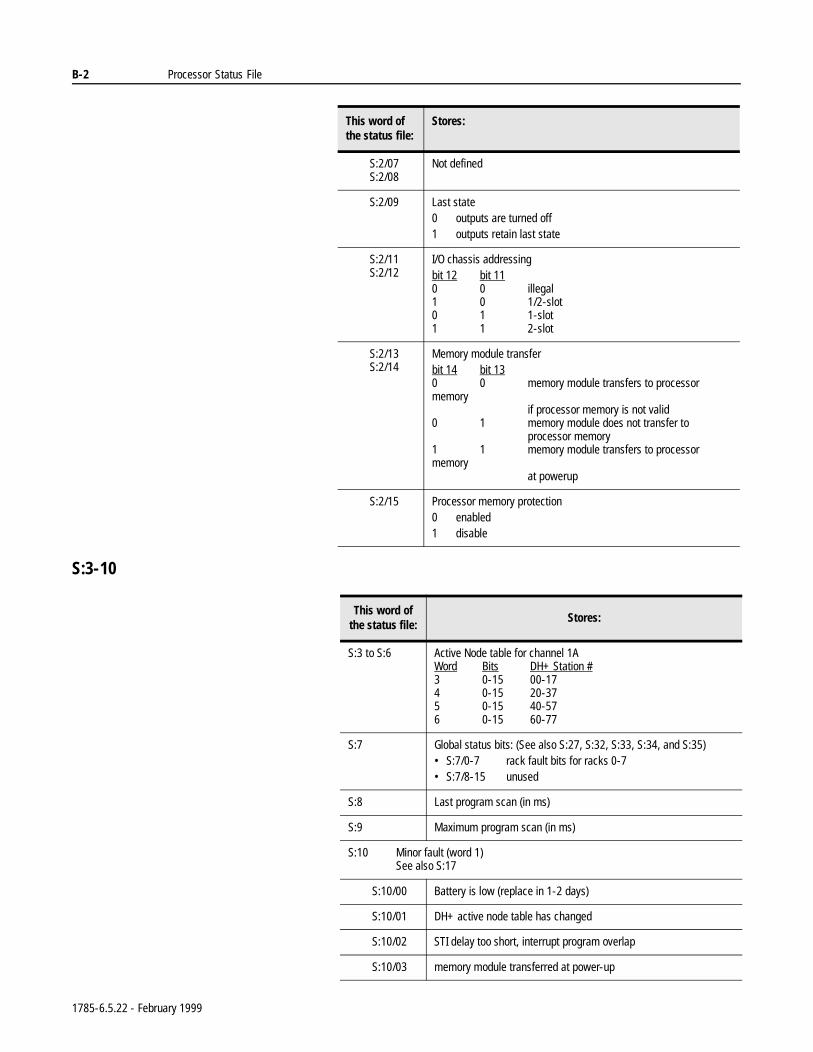
B-2 Processor Status File
S:3-10
S:2/07S:2/08
Not defined
S:2/09 Last state0 outputs are turned off1 outputs retain last state
S:2/11S:2/12
I/O chassis addressingbit 12 bit 110 0 illegal1 0 1/2-slot0 1 1-slot1 1 2-slot
S:2/13S:2/14
Memory module transferbit 14 bit 130 0 memory module transfers to processor memory
if processor memory is not valid0 1 memory module does not transfer to
processor memory1 1 memory module transfers to processor memory
at powerup
S:2/15 Processor memory protection0 enabled1 disable
This word ofthe status file:
Stores:
This word of the status file:
Stores:
S:3 to S:6 Active Node table for channel 1AWord Bits DH+ Station #3 0-15 00-174 0-15 20-375 0-15 40-576 0-15 60-77
S:7 Global status bits: (See also S:27, S:32, S:33, S:34, and S:35)• S:7/0-7 rack fault bits for racks 0-7• S:7/8-15 unused
S:8 Last program scan (in ms)
S:9 Maximum program scan (in ms)
S:10 Minor fault (word 1)See also S:17
S:10/00 Battery is low (replace in 1-2 days)
S:10/01 DH+ active node table has changed
S:10/02 STI delay too short, interrupt program overlap
S:10/03 memory module transferred at power-up
1785-6.5.22 - February 1999
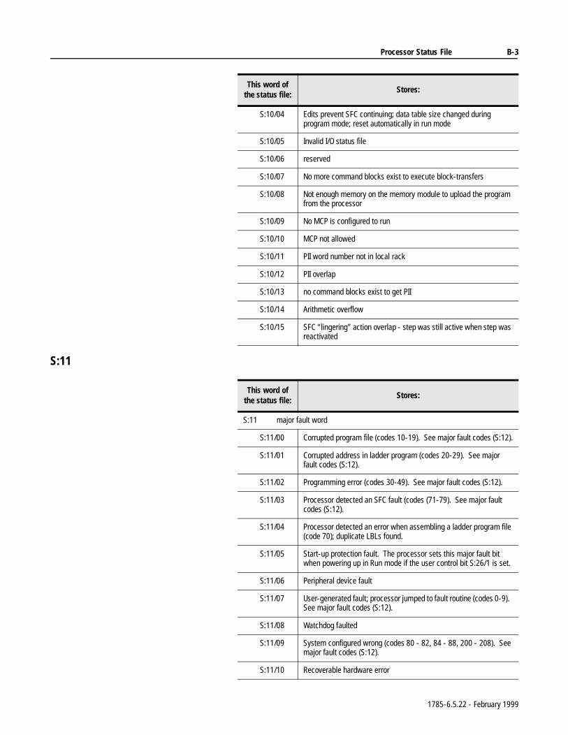
Processor Status File B-3
S:11
S:10/04 Edits prevent SFC continuing; data table size changed during program mode; reset automatically in run mode
S:10/05 Invalid I/O status file
S:10/06 reserved
S:10/07 No more command blocks exist to execute block-transfers
S:10/08 Not enough memory on the memory module to upload the program from the processor
S:10/09 No MCP is configured to run
S:10/10 MCP not allowed
S:10/11 PII word number not in local rack
S:10/12 PII overlap
S:10/13 no command blocks exist to get PII
S:10/14 Arithmetic overflow
S:10/15 SFC “lingering” action overlap - step was still active when step was reactivated
This word of the status file:
Stores:
This word of the status file:
Stores:
S:11 major fault word
S:11/00 Corrupted program file (codes 10-19). See major fault codes (S:12).
S:11/01 Corrupted address in ladder program (codes 20-29). See major fault codes (S:12).
S:11/02 Programming error (codes 30-49). See major fault codes (S:12).
S:11/03 Processor detected an SFC fault (codes (71-79). See major fault codes (S:12).
S:11/04 Processor detected an error when assembling a ladder program file (code 70); duplicate LBLs found.
S:11/05 Start-up protection fault. The processor sets this major fault bit when powering up in Run mode if the user control bit S:26/1 is set.
S:11/06 Peripheral device fault
S:11/07 User-generated fault; processor jumped to fault routine (codes 0-9). See major fault codes (S:12).
S:11/08 Watchdog faulted
S:11/09 System configured wrong (codes 80 - 82, 84 - 88, 200 - 208). See major fault codes (S:12).
S:11/10 Recoverable hardware error
1785-6.5.22 - February 1999
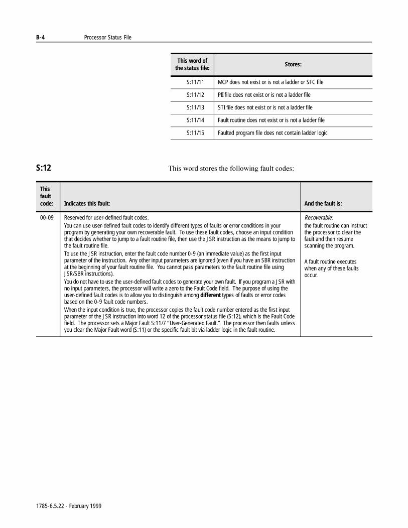
B-4 Processor Status File
S:12 7KLVZRUGVWRUHVWKHIROORZLQJIDXOWFRGHV
S:11/11 MCP does not exist or is not a ladder or SFC file
S:11/12 PII file does not exist or is not a ladder file
S:11/13 STI file does not exist or is not a ladder file
S:11/14 Fault routine does not exist or is not a ladder file
S:11/15 Faulted program file does not contain ladder logic
This word of the status file:
Stores:
This fault code: Indicates this fault: And the fault is:
00-09 Reserved for user-defined fault codes.You can use user-defined fault codes to identify different types of faults or error conditions in your program by generating your own recoverable fault. To use these fault codes, choose an input condition that decides whether to jump to a fault routine file, then use the JSR instruction as the means to jump to the fault routine file. To use the JSR instruction, enter the fault code number 0-9 (an immediate value) as the first input parameter of the instruction. Any other input parameters are ignored (even if you have an SBR instruction at the beginning of your fault routine file. You cannot pass parameters to the fault routine file using JSR/SBR instructions). You do not have to use the user-defined fault codes to generate your own fault. If you program a JSR with no input parameters, the processor will write a zero to the Fault Code field. The purpose of using the user-defined fault codes is to allow you to distinguish among different types of faults or error codes based on the 0-9 fault code numbers.When the input condition is true, the processor copies the fault code number entered as the first input parameter of the JSR instruction into word 12 of the processor status file (S:12), which is the Fault Code field. The processor sets a Major Fault S:11/7 “User-Generated Fault.” The processor then faults unless you clear the Major Fault word (S:11) or the specific fault bit via ladder logic in the fault routine.
Recoverable: the fault routine can instruct the processor to clear the fault and then resume scanning the program.
A fault routine executes when any of these faults occur.
1785-6.5.22 - February 1999
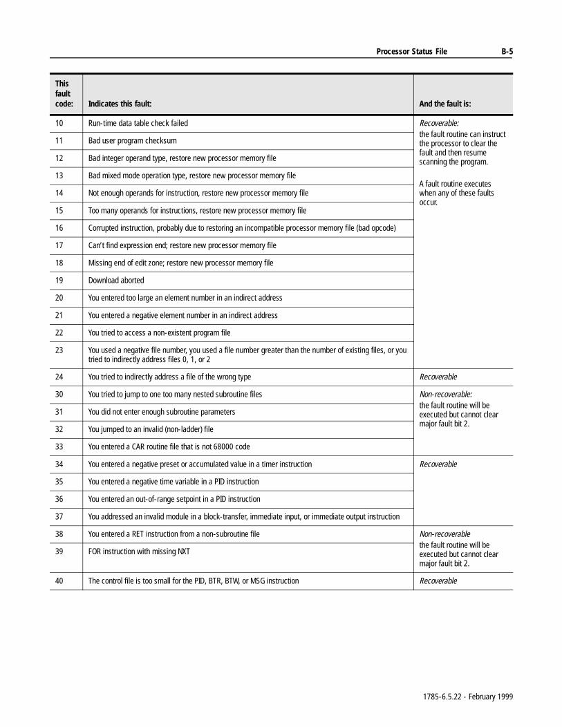
Processor Status File B-5
10 Run-time data table check failed Recoverable: the fault routine can instruct the processor to clear the fault and then resume scanning the program.
A fault routine executes when any of these faults occur.
11 Bad user program checksum
12 Bad integer operand type, restore new processor memory file
13 Bad mixed mode operation type, restore new processor memory file
14 Not enough operands for instruction, restore new processor memory file
15 Too many operands for instructions, restore new processor memory file
16 Corrupted instruction, probably due to restoring an incompatible processor memory file (bad opcode)
17 Can’t find expression end; restore new processor memory file
18 Missing end of edit zone; restore new processor memory file
19 Download aborted
20 You entered too large an element number in an indirect address
21 You entered a negative element number in an indirect address
22 You tried to access a non-existent program file
23 You used a negative file number, you used a file number greater than the number of existing files, or you tried to indirectly address files 0, 1, or 2
24 You tried to indirectly address a file of the wrong type Recoverable
30 You tried to jump to one too many nested subroutine files Non-recoverable:the fault routine will be executed but cannot clear major fault bit 2.
31 You did not enter enough subroutine parameters
32 You jumped to an invalid (non-ladder) file
33 You entered a CAR routine file that is not 68000 code
34 You entered a negative preset or accumulated value in a timer instruction Recoverable
35 You entered a negative time variable in a PID instruction
36 You entered an out-of-range setpoint in a PID instruction
37 You addressed an invalid module in a block-transfer, immediate input, or immediate output instruction
38 You entered a RET instruction from a non-subroutine file Non-recoverablethe fault routine will be executed but cannot clear major fault bit 2.
39 FOR instruction with missing NXT
40 The control file is too small for the PID, BTR, BTW, or MSG instruction Recoverable
This fault code: Indicates this fault: And the fault is:
1785-6.5.22 - February 1999
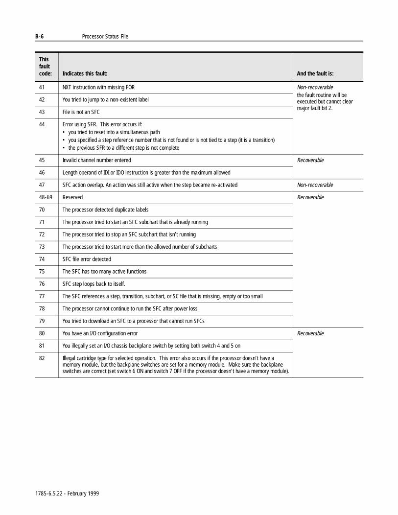
B-6 Processor Status File
41 NXT instruction with missing FOR Non-recoverablethe fault routine will be executed but cannot clear major fault bit 2.
42 You tried to jump to a non-existent label
43 File is not an SFC
44 Error using SFR. This error occurs if:• you tried to reset into a simultaneous path• you specified a step reference number that is not found or is not tied to a step (it is a transition)• the previous SFR to a different step is not complete
45 Invalid channel number entered Recoverable
46 Length operand of IDI or IDO instruction is greater than the maximum allowed
47 SFC action overlap. An action was still active when the step became re-activated Non-recoverable
48-69 Reserved Recoverable
70 The processor detected duplicate labels
71 The processor tried to start an SFC subchart that is already running
72 The processor tried to stop an SFC subchart that isn’t running
73 The processor tried to start more than the allowed number of subcharts
74 SFC file error detected
75 The SFC has too many active functions
76 SFC step loops back to itself.
77 The SFC references a step, transition, subchart, or SC file that is missing, empty or too small
78 The processor cannot continue to run the SFC after power loss
79 You tried to download an SFC to a processor that cannot run SFCs
80 You have an I/O configuration error Recoverable
81 You illegally set an I/O chassis backplane switch by setting both switch 4 and 5 on
82 Illegal cartridge type for selected operation. This error also occurs if the processor doesn’t have a memory module, but the backplane switches are set for a memory module. Make sure the backplane switches are correct (set switch 6 ON and switch 7 OFF if the processor doesn’t have a memory module).
This fault code: Indicates this fault: And the fault is:
1785-6.5.22 - February 1999
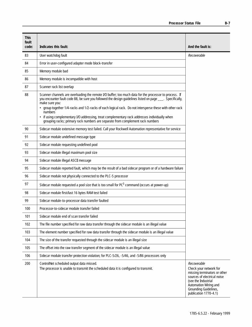
Processor Status File B-7
83 User watchdog fault Recoverable
84 Error in user-configured adapter mode block-transfer
85 Memory module bad
86 Memory module is incompatible with host
87 Scanner rack list overlap
88 Scanner channels are overloading the remote I/O buffer; too much data for the processor to process. If you encounter fault code 88, be sure you followed the design guidelines listed on page ___. Specifically, make sure you:• group together 1/4-racks and 1/2-racks of each logical rack. Do not intersperse these with other rack
numbers• if using complementary I/O addressing, treat complementary rack addresses individually when
grouping racks; primary rack numbers are separate from complement rack numbers
90 Sidecar module extensive memory test failed. Call your Rockwell Automation representative for service
91 Sidecar module undefined message type
92 Sidecar module requesting undefined pool
93 Sidecar module illegal maximum pool size
94 Sidecar module illegal ASCII message
95 Sidecar module reported fault, which may be the result of a bad sidecar program or of a hardware failure
96 Sidecar module not physically connected to the PLC-5 processor
97 Sidecar module requested a pool size that is too small for PC3 command (occurs at power-up)
98 Sidecar module first/last 16 bytes RAM test failed
99 Sidecar module-to-processor data transfer faulted
100 Processor-to-sidecar module transfer failed
101 Sidecar module end of scan transfer failed
102 The file number specified for raw data transfer through the sidecar module is an illegal value
103 The element number specified for raw data transfer through the sidecar module is an illegal value
104 The size of the transfer requested through the sidecar module is an illegal size
105 The offset into the raw transfer segment of the sidecar module is an illegal value
106 Sidecar module transfer protection violation; for PLC-5/26, -5/46, and -5/86 processors only
200 ControlNet scheduled output data missed.The processor is unable to transmit the scheduled data it is configured to transmit.
RecoverableCheck your network for missing terminators or other sources of electrical noise (see the Industrial Automation Wiring and Grounding Guidelines, publication 1770-4.1)
This fault code: Indicates this fault: And the fault is:
1785-6.5.22 - February 1999
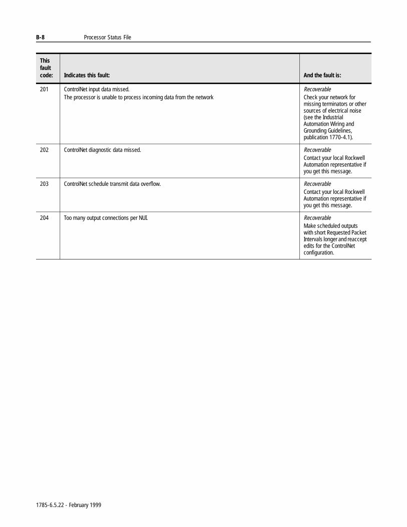
B-8 Processor Status File
201 ControlNet input data missed.The processor is unable to process incoming data from the network
RecoverableCheck your network for missing terminators or other sources of electrical noise (see the Industrial Automation Wiring and Grounding Guidelines, publication 1770-4.1).
202 ControlNet diagnostic data missed. RecoverableContact your local Rockwell Automation representative if you get this message.
203 ControlNet schedule transmit data overflow. RecoverableContact your local Rockwell Automation representative if you get this message.
204 Too many output connections per NUI. RecoverableMake scheduled outputs with short Requested Packet Intervals longer and reaccept edits for the ControlNet configuration.
This fault code: Indicates this fault: And the fault is:
1785-6.5.22 - February 1999
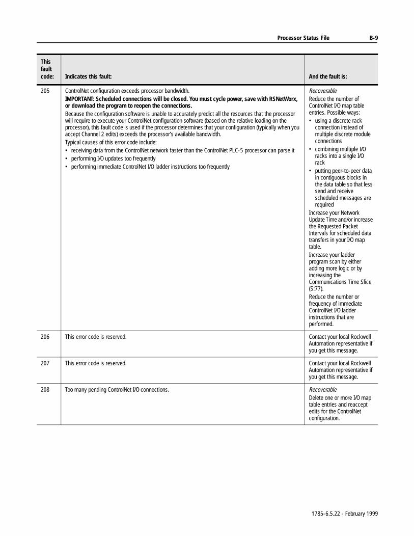
Processor Status File B-9
205 ControlNet configuration exceeds processor bandwidth.IMPORTANT: Scheduled connections will be closed. You must cycle power, save with RSNetWorx, or download the program to reopen the connections.Because the configuration software is unable to accurately predict all the resources that the processor will require to execute your ControlNet configuration software (based on the relative loading on the processor), this fault code is used if the processor determines that your configuration (typically when you accept Channel 2 edits) exceeds the processor’s available bandwidth.Typical causes of this error code include: • receiving data from the ControlNet network faster than the ControlNet PLC-5 processor can parse it• performing I/O updates too frequently• performing immediate ControlNet I/O ladder instructions too frequently
RecoverableReduce the number of ControlNet I/O map table entries. Possible ways: • using a discrete rack
connection instead of multiple discrete module connections
• combining multiple I/O racks into a single I/O rack
• putting peer-to-peer data in contiguous blocks in the data table so that less send and receive scheduled messages are required
Increase your Network Update Time and/or increase the Requested Packet Intervals for scheduled data transfers in your I/O map table.Increase your ladder program scan by either adding more logic or by increasing the Communications Time Slice (S:77).Reduce the number or frequency of immediate ControlNet I/O ladder instructions that are performed.
206 This error code is reserved. Contact your local Rockwell Automation representative if you get this message.
207 This error code is reserved. Contact your local Rockwell Automation representative if you get this message.
208 Too many pending ControlNet I/O connections. RecoverableDelete one or more I/O map table entries and reaccept edits for the ControlNet configuration.
This fault code: Indicates this fault: And the fault is:
1785-6.5.22 - February 1999
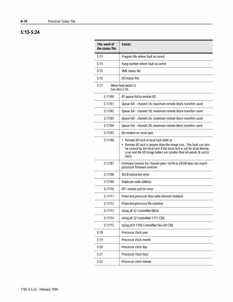
B-10 Processor Status File
S:13-S:24
This word ofthe status file:
Stores:
S:13 Program file where fault occurred
S:14 Rung number where fault occurred
S:15 VME status file
S:16 I/O status File
S:17 Minor fault (word 2)See also S:10.
S:17/00 BT queue full to remote I/O
S:17/01 Queue full - channel 1A; maximum remote block-transfers used
S:17/02 Queue full - channel 1B; maximum remote block-transfers used
S:17/03 Queue full - channel 2A; maximum remote block-transfers used
S:17/04 Queue full - channel 2B; maximum remote block transfers used
S:17/05 No modem on serial port
S:17/06 • Remote I/O rack in local rack table or • Remote I/O rack is greater than the image size. This fault can also
be caused by the local rack if the local rack is set for octal density scan and the I/O image tables are smaller than 64 words (8 racks) each.
S:17/07 Firmware revision for channel pairs 1A/1B or 2A/2B does not match processor firmware revision
S:17/08 ASCII instruction error
S:17/09 Duplicate node address
S:17/10 DF1 master poll list error
S:17/11 Protected processor data table element violation
S:17/12 Protected processor file violation
S:17/13 Using all 32 ControlNet MSGs
S:17/14 Using all 32 ControlNet 1771 CIOs
S:17/15 Using all 8 1794 ControlNet Flex I/O CIOs
S:18 Processor clock year
S:19 Processor clock month
S:20 Processor clock day
S:21 Processor clock hour
S:22 Processor clock minute
1785-6.5.22 - February 1999
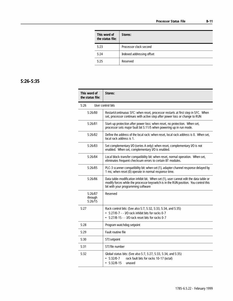
Processor Status File B-11
S:26-S:35
S:23 Processor clock second
S:24 Indexed addressing offset
S:25 Reserved
This word ofthe status file:
Stores:
This word ofthe status file:
Stores:
S:26 User control bits
S:26/00 Restart/continuous SFC: when reset, processor restarts at first step in SFC. When set, processor continues with active step after power loss or change to RUN
S:26/01 Start-up protection after power loss: when reset, no protection. When set, processor sets major fault bit S:11/5 when powering up in run mode.
S:26/02 Define the address of the local rack: when reset, local rack address is 0. When set, local rack address is 1.
S:26/03 Set complementary I/O (series A only): when reset, complementary I/O is not enabled. When set, complementary I/O is enabled.
S:26/04 Local block-transfer compatibility bit: when reset, normal operation. When set, eliminates frequent checksum errors to certain BT modules.
S:26/05 PLC-3 scanner compatibility bit: when set (1), adapter channel response delayed by 1 ms; when reset (0) operate in normal response time.
S:26/06 Data table-modification inhibit bit. When set (1), user cannot edit the data table or modify forces while the processor keyswitch is in the RUN position. You control this bit with your programming software
S:26/07throughS:26/15
Reserved
S:27 Rack control bits: (See also S:7, S:32, S:33, S:34, and S:35)• S:27/0-7 - - I/O rack inhibit bits for racks 0-7• S:27/8-15 - - I/O rack reset bits for racks 0-7
S:28 Program watchdog setpoint
S:29 Fault routine file
S:30 STI setpoint
S:31 STI file number
S:32 Global status bits: (See also S:7, S:27, S:33, S:34, and S:35)• S:32/0-7 rack fault bits for racks 10-17 (octal)• S:32/8-15 unused
1785-6.5.22 - February 1999
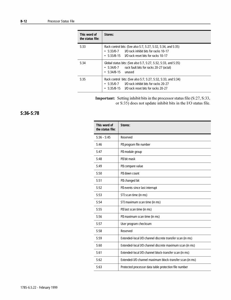
B-12 Processor Status File
,PSRUWDQW6HWWLQJLQKLELWELWVLQWKHSURFHVVRUVWDWXVILOH66RU6GRHVQRWXSGDWHLQKLELWELWVLQWKH,2VWDWXVILOH
S:36-S:78
S:33 Rack control bits: (See also S:7, S:27, S:32, S:34, and S:35)• S:33/0-7 I/O rack inhibit bits for racks 10-17• S:33/8-15 I/O rack reset bits for racks 10-17
S:34 Global status bits: (See also S:7, S:27, S:32, S:33, and S:35)• S:34/0-7 rack fault bits for racks 20-27 (octal)• S:34/8-15 unused
S:35 Rack control bits: (See also S:7, S:27, S:32, S:33, and S:34)• S:35/0-7 I/O rack inhibit bits for racks 20-27• S:35/8-15 I/O rack reset bits for racks 20-27
This word ofthe status file:
Stores:
This word ofthe status file:
Stores:
S:36 - S:45 Reserved
S:46 PII program file number
S:47 PII module group
S:48 PII bit mask
S:49 PII compare value
S:50 PII down count
S:51 PII changed bit
S:52 PII events since last interrupt
S:53 STI scan time (in ms)
S:54 STI maximum scan time (in ms)
S:55 PII last scan time (in ms)
S:56 PII maximum scan time (in ms)
S:57 User program checksum
S:58 Reserved
S:59 Extended-local I/O channel discrete transfer scan (in ms)
S:60 Extended-local I/O channel discrete maximum scan (in ms)
S:61 Extended-local I/O channel block-transfer scan (in ms)
S:62 Extended-I/O channel maximum block-transfer scan (in ms)
S:63 Protected processor data table protection file number
1785-6.5.22 - February 1999
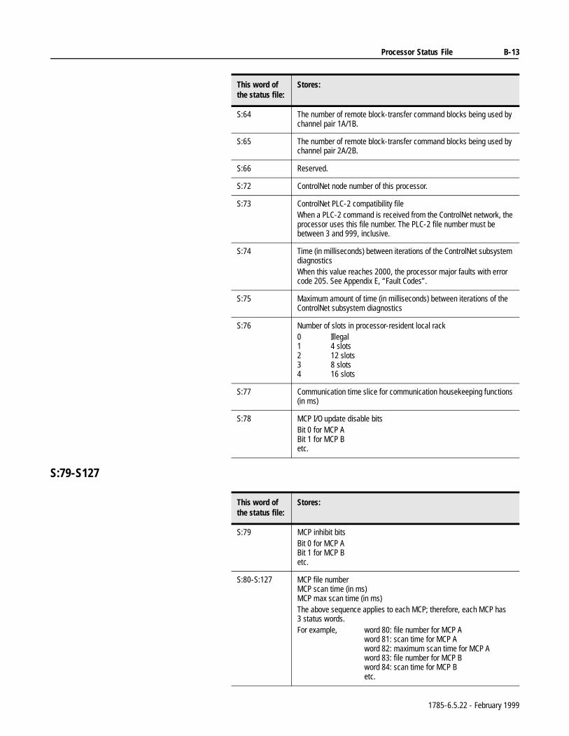
Processor Status File B-13
S:79-S127
S:64 The number of remote block-transfer command blocks being used by channel pair 1A/1B.
S:65 The number of remote block-transfer command blocks being used by channel pair 2A/2B.
S:66 Reserved.
S:72 ControlNet node number of this processor.
S:73 ControlNet PLC-2 compatibility fileWhen a PLC-2 command is received from the ControlNet network, the processor uses this file number. The PLC-2 file number must be between 3 and 999, inclusive.
S:74 Time (in milliseconds) between iterations of the ControlNet subsystem diagnosticsWhen this value reaches 2000, the processor major faults with error code 205. See Appendix E, “Fault Codes”.
S:75 Maximum amount of time (in milliseconds) between iterations of the ControlNet subsystem diagnostics
S:76 Number of slots in processor-resident local rack0 Illegal1 4 slots2 12 slots3 8 slots4 16 slots
S:77 Communication time slice for communication housekeeping functions (in ms)
S:78 MCP I/O update disable bitsBit 0 for MCP ABit 1 for MCP Betc.
This word ofthe status file:
Stores:
This word ofthe status file:
Stores:
S:79 MCP inhibit bitsBit 0 for MCP ABit 1 for MCP Betc.
S:80-S:127 MCP file numberMCP scan time (in ms)MCP max scan time (in ms)The above sequence applies to each MCP; therefore, each MCP has 3 status words.For example, word 80: file number for MCP A
word 81: scan time for MCP Aword 82: maximum scan time for MCP Aword 83: file number for MCP Bword 84: scan time for MCP Betc.
1785-6.5.22 - February 1999
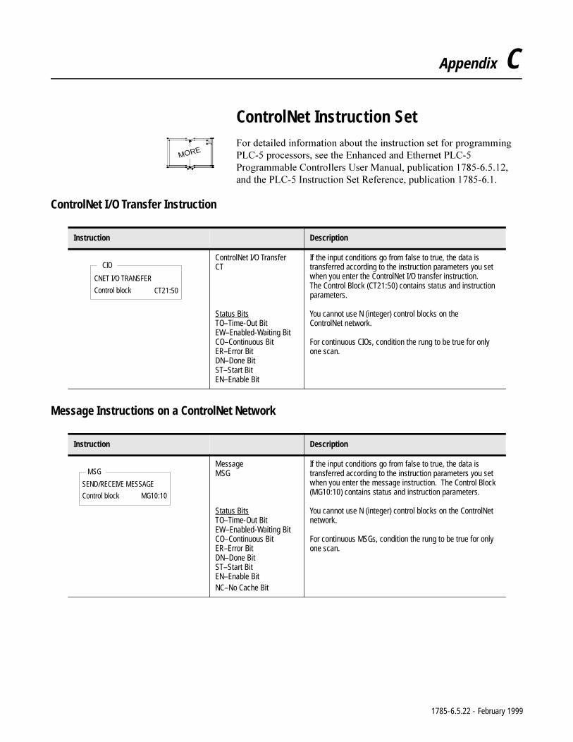
Appendix C
ControlNet Instruction Set)RUGHWDLOHGLQIRUPDWLRQDERXWWKHLQVWUXFWLRQVHWIRUSURJUDPPLQJ3/&SURFHVVRUVVHHWKH(QKDQFHGDQG(WKHUQHW3/&3URJUDPPDEOH&RQWUROOHUV8VHU0DQXDOSXEOLFDWLRQDQGWKH3/&,QVWUXFWLRQ6HW5HIHUHQFHSXEOLFDWLRQ
ControlNet I/O Transfer Instruction
Message Instructions on a ControlNet Network
MORE
Instruction Description
ControlNet I/O Transfer CT
Status BitsTO–Time-Out BitEW–Enabled-Waiting BitCO–Continuous BitER–Error BitDN–Done BitST–Start BitEN–Enable Bit
If the input conditions go from false to true, the data is transferred according to the instruction parameters you set when you enter the ControlNet I/O transfer instruction. The Control Block (CT21:50) contains status and instruction parameters.
You cannot use N (integer) control blocks on the ControlNet network.
For continuous CIOs, condition the rung to be true for only one scan.
Instruction Description
Message MSG
Status BitsTO–Time-Out BitEW–Enabled-Waiting BitCO–Continuous BitER–Error BitDN–Done BitST–Start BitEN–Enable BitNC–No Cache Bit
If the input conditions go from false to true, the data is transferred according to the instruction parameters you set when you enter the message instruction. The Control Block (MG10:10) contains status and instruction parameters.
You cannot use N (integer) control blocks on the ControlNet network.
For continuous MSGs, condition the rung to be true for only one scan.
CIO
CNET I/O TRANSFER
Control block CT21:50
MSG
SEND/RECEIVE MESSAGE
Control block MG10:10
1785-6.5.22 - February 1999
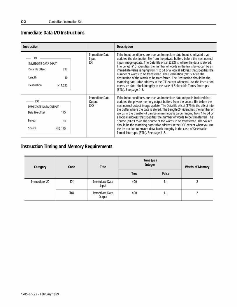
C-2 ControlNet Instruction Set
Immediate Data I/O Instructions
Instruction Timing and Memory Requirements
Instruction Description
Immediate Data Input IDI
If the input conditions are true, an immediate data input is initiated that updates the destination file from the private buffers before the next normal input-image update. The Data file offset (232) is where the data is stored. The Length (10) identifies the number of words in the transfer–it can be an immediate value ranging from 1 to 64 or a logical address that specifies the number of words to be transferred. The Destination (N11:232) is the destination of the words to be transferred. The Destination should be the matching data-table address in the DIF except when you use the instruction to ensure data-block integrity in the case of Selectable Times Interrupts (STIs). See page 4-8.
Immediate Data OutputIDO
If the input conditions are true, an immediate data output is initiated that updates the private memory output buffers from the source file before the next normal output-image update. The Data file offset (175) is the offset into the buffer where the data is stored. The Length (24) identifies the number of words in the transfer–it can be an immediate value ranging from 1 to 64 or a logical address that specifies the number of words to be transferred. The Source (N12:175) is the source of the words to be transferred. The Source should be the matching data-table address in the DOF except when you use the instruction to ensure data-block integrity in the case of Selectable Timed Interrupts (STIs). See page 4-8.
Category Code Title
Time (µs)Integer
Words of Memory
True False
Immediate I/O IDI Immediate Data Input
400 1.1 2
IDO Immediate Data Output
400 1.1 2
IDI
IMMEDIATE DATA INPUT
Data file offset
Length
232
10
Destination N11:232
IDO
IMMEDIATE DATA OUTPUT
Data file offset
Length
175
24
Source N12:175
1785-6.5.22 - February 1999
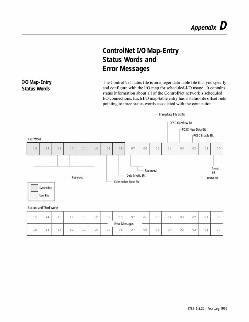
Appendix D
ControlNet I/O Map-Entry Status Words and Error Messages
I/O Map-Entry Status Words
7KH&RQWURO1HWVWDWXVILOHLVDQLQWHJHUGDWDWDEOHILOHWKDW\RXVSHFLI\DQGFRQILJXUHZLWKWKH,2PDSIRUVFKHGXOHG,2XVDJH,WFRQWDLQVVWDWXVLQIRUPDWLRQDERXWDOORIWKH&RQWURO1HWQHWZRUN¶VVFKHGXOHG,2FRQQHFWLRQV(DFK,2PDSWDEOHHQWU\KDVDVWDWXVILOHRIIVHWILHOGSRLQWLQJWRWKUHHVWDWXVZRUGVDVVRFLDWHGZLWKWKHFRQQHFWLRQ
0000102003040500607080091011120131415
Reset Bit
Inhibit BitData Invalid Bit
Connection Error BitReserved
Reserved
First Word
Second and Third Words
Error Messages
0000102003040500607080091011120131415
0000102003040500607080091011120131415
PCSC Overflow Bit
PCSC New Data Bit
PCSC Enable Bit
Immediate Inhibit Bit
System Bits
User Bits
1785-6.5.22 - February 1999
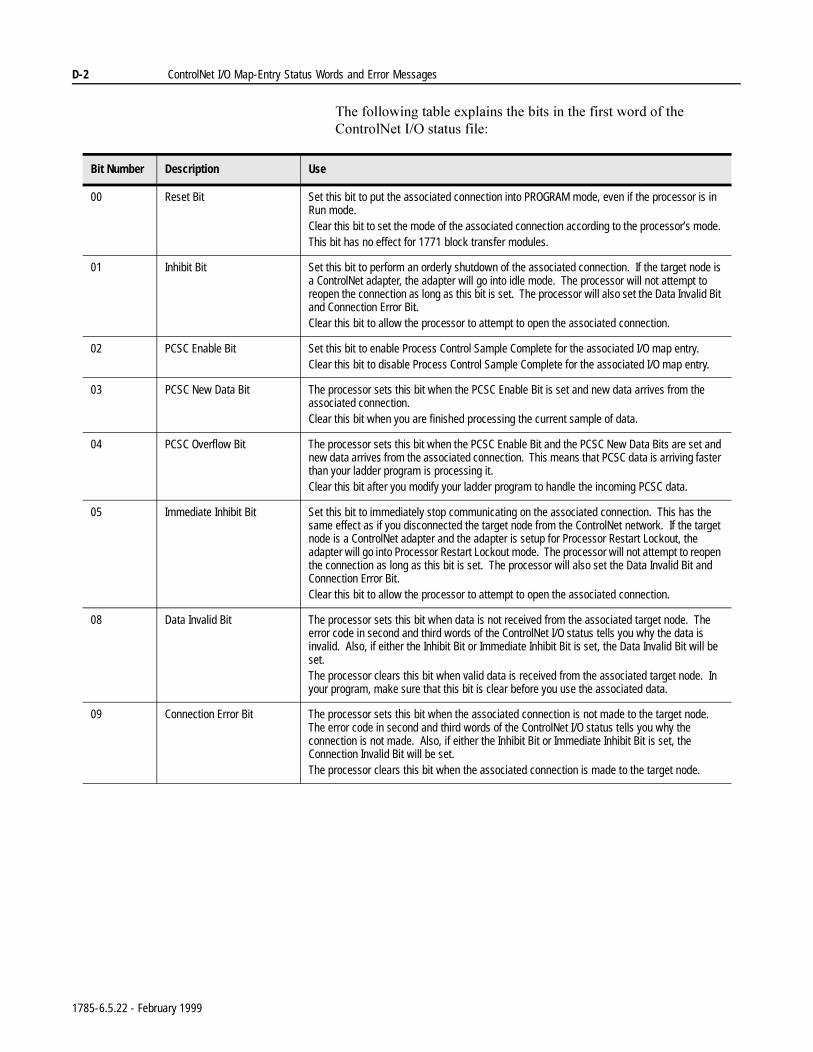
D-2 ControlNet I/O Map-Entry Status Words and Error Messages
7KHIROORZLQJWDEOHH[SODLQVWKHELWVLQWKHILUVWZRUGRIWKH&RQWURO1HW,2VWDWXVILOH
Bit Number Description Use
00 Reset Bit Set this bit to put the associated connection into PROGRAM mode, even if the processor is in Run mode.Clear this bit to set the mode of the associated connection according to the processor’s mode. This bit has no effect for 1771 block transfer modules.
01 Inhibit Bit Set this bit to perform an orderly shutdown of the associated connection. If the target node is a ControlNet adapter, the adapter will go into idle mode. The processor will not attempt to reopen the connection as long as this bit is set. The processor will also set the Data Invalid Bit and Connection Error Bit.Clear this bit to allow the processor to attempt to open the associated connection.
02 PCSC Enable Bit Set this bit to enable Process Control Sample Complete for the associated I/O map entry.Clear this bit to disable Process Control Sample Complete for the associated I/O map entry.
03 PCSC New Data Bit The processor sets this bit when the PCSC Enable Bit is set and new data arrives from the associated connection.Clear this bit when you are finished processing the current sample of data.
04 PCSC Overflow Bit The processor sets this bit when the PCSC Enable Bit and the PCSC New Data Bits are set and new data arrives from the associated connection. This means that PCSC data is arriving faster than your ladder program is processing it.Clear this bit after you modify your ladder program to handle the incoming PCSC data.
05 Immediate Inhibit Bit Set this bit to immediately stop communicating on the associated connection. This has the same effect as if you disconnected the target node from the ControlNet network. If the target node is a ControlNet adapter and the adapter is setup for Processor Restart Lockout, the adapter will go into Processor Restart Lockout mode. The processor will not attempt to reopen the connection as long as this bit is set. The processor will also set the Data Invalid Bit and Connection Error Bit.Clear this bit to allow the processor to attempt to open the associated connection.
08 Data Invalid Bit The processor sets this bit when data is not received from the associated target node. The error code in second and third words of the ControlNet I/O status tells you why the data is invalid. Also, if either the Inhibit Bit or Immediate Inhibit Bit is set, the Data Invalid Bit will be set.The processor clears this bit when valid data is received from the associated target node. In your program, make sure that this bit is clear before you use the associated data.
09 Connection Error Bit The processor sets this bit when the associated connection is not made to the target node. The error code in second and third words of the ControlNet I/O status tells you why the connection is not made. Also, if either the Inhibit Bit or Immediate Inhibit Bit is set, the Connection Invalid Bit will be set.The processor clears this bit when the associated connection is made to the target node.
1785-6.5.22 - February 1999
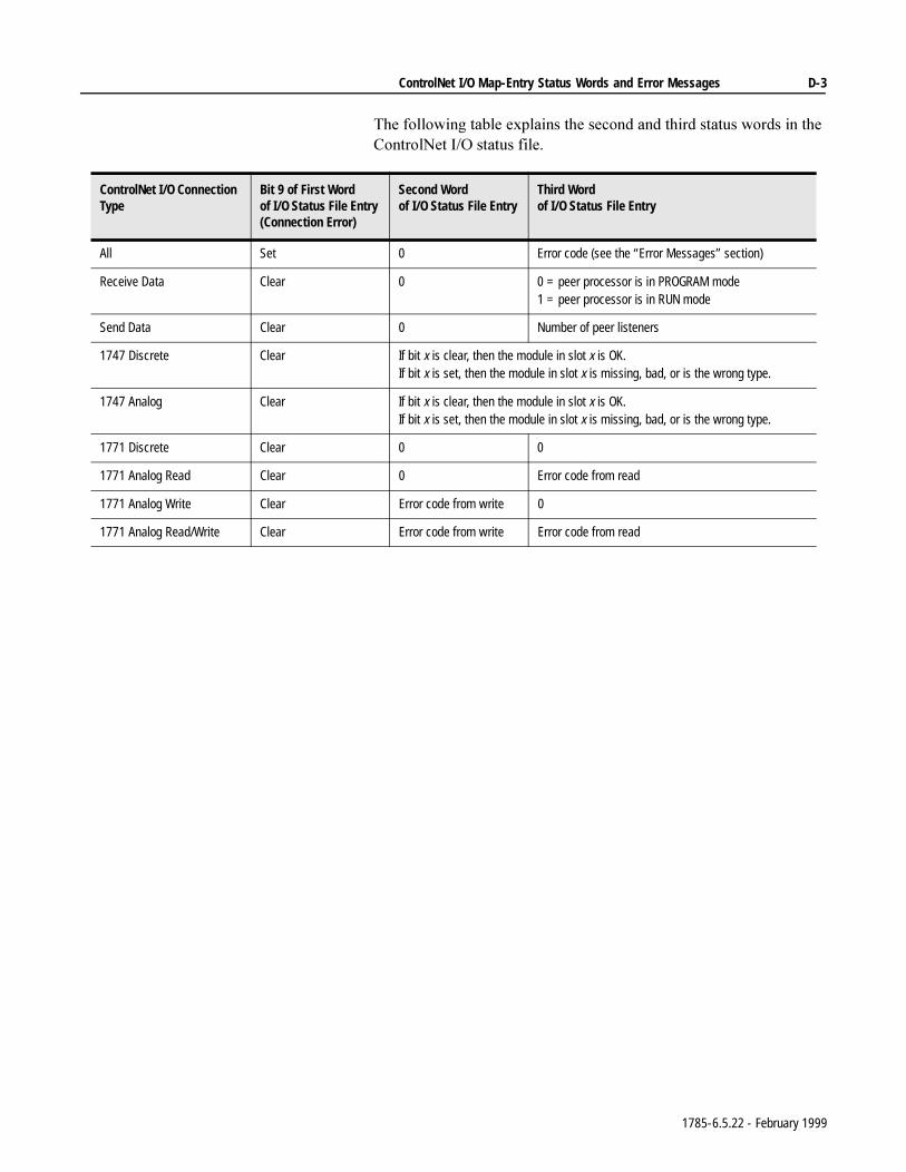
ControlNet I/O Map-Entry Status Words and Error Messages D-3
7KHIROORZLQJWDEOHH[SODLQVWKHVHFRQGDQGWKLUGVWDWXVZRUGVLQWKH&RQWURO1HW,2VWDWXVILOH
ControlNet I/O Connection Type
Bit 9 of First Wordof I/O Status File Entry (Connection Error)
Second Wordof I/O Status File Entry
Third Wordof I/O Status File Entry
All Set 0 Error code (see the “Error Messages” section)
Receive Data Clear 0 0 = peer processor is in PROGRAM mode1 = peer processor is in RUN mode
Send Data Clear 0 Number of peer listeners
1747 Discrete Clear If bit x is clear, then the module in slot x is OK.If bit x is set, then the module in slot x is missing, bad, or is the wrong type.
1747 Analog Clear If bit x is clear, then the module in slot x is OK.If bit x is set, then the module in slot x is missing, bad, or is the wrong type.
1771 Discrete Clear 0 0
1771 Analog Read Clear 0 Error code from read
1771 Analog Write Clear Error code from write 0
1771 Analog Read/Write Clear Error code from write Error code from read
1785-6.5.22 - February 1999
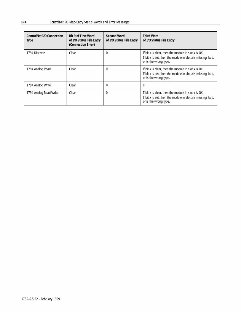
D-4 ControlNet I/O Map-Entry Status Words and Error Messages
1794 Discrete Clear 0 If bit x is clear, then the module in slot x is OK.If bit x is set, then the module in slot x is missing, bad, or is the wrong type.
1794 Analog Read Clear 0 If bit x is clear, then the module in slot x is OK.If bit x is set, then the module in slot x is missing, bad, or is the wrong type.
1794 Analog Write Clear 0 0
1794 Analog Read/Write Clear 0 If bit x is clear, then the module in slot x is OK.If bit x is set, then the module in slot x is missing, bad, or is the wrong type.
ControlNet I/O Connection Type
Bit 9 of First Wordof I/O Status File Entry (Connection Error)
Second Wordof I/O Status File Entry
Third Wordof I/O Status File Entry
1785-6.5.22 - February 1999
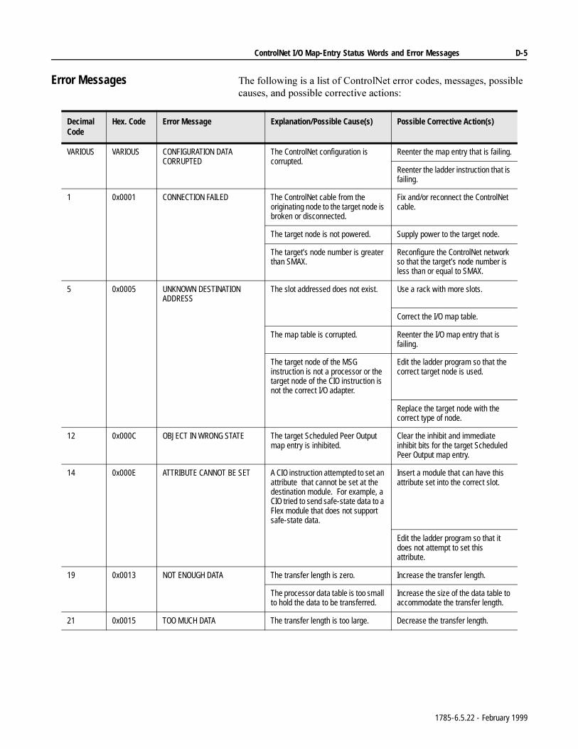
ControlNet I/O Map-Entry Status Words and Error Messages D-5
Error Messages 7KHIROORZLQJLVDOLVWRI&RQWURO1HWHUURUFRGHVPHVVDJHVSRVVLEOHFDXVHVDQGSRVVLEOHFRUUHFWLYHDFWLRQV
Decimal Code
Hex. Code Error Message Explanation/Possible Cause(s) Possible Corrective Action(s)
VARIOUS VARIOUS CONFIGURATION DATA CORRUPTED
The ControlNet configuration is corrupted.
Reenter the map entry that is failing.
Reenter the ladder instruction that is failing.
1 0x0001 CONNECTION FAILED The ControlNet cable from the originating node to the target node is broken or disconnected.
Fix and/or reconnect the ControlNet cable.
The target node is not powered. Supply power to the target node.
The target’s node number is greater than SMAX.
Reconfigure the ControlNet network so that the target’s node number is less than or equal to SMAX.
5 0x0005 UNKNOWN DESTINATION ADDRESS
The slot addressed does not exist. Use a rack with more slots.
Correct the I/O map table.
The map table is corrupted. Reenter the I/O map entry that is failing.
The target node of the MSG instruction is not a processor or the target node of the CIO instruction is not the correct I/O adapter.
Edit the ladder program so that the correct target node is used.
Replace the target node with the correct type of node.
12 0x000C OBJECT IN WRONG STATE The target Scheduled Peer Output map entry is inhibited.
Clear the inhibit and immediate inhibit bits for the target Scheduled Peer Output map entry.
14 0x000E ATTRIBUTE CANNOT BE SET A CIO instruction attempted to set an attribute that cannot be set at the destination module. For example, a CIO tried to send safe-state data to a Flex module that does not support safe-state data.
Insert a module that can have this attribute set into the correct slot.
Edit the ladder program so that it does not attempt to set this attribute.
19 0x0013 NOT ENOUGH DATA The transfer length is zero. Increase the transfer length.
The processor data table is too small to hold the data to be transferred.
Increase the size of the data table to accommodate the transfer length.
21 0x0015 TOO MUCH DATA The transfer length is too large. Decrease the transfer length.
1785-6.5.22 - February 1999
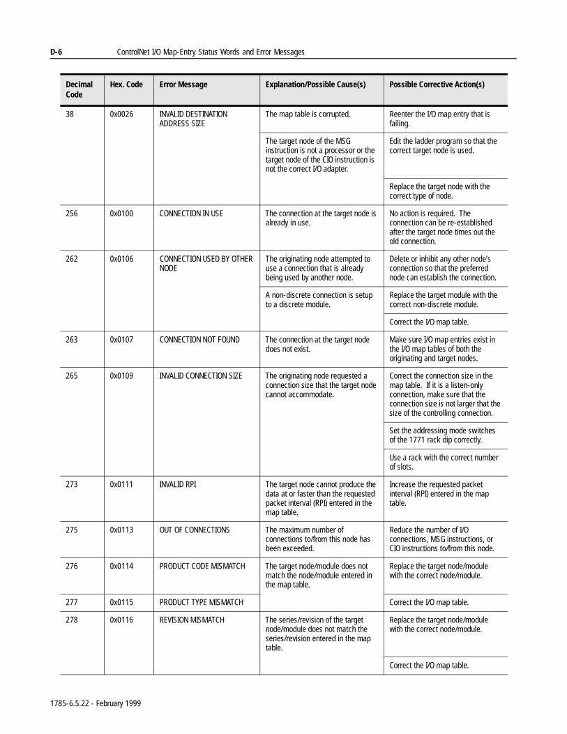
D-6 ControlNet I/O Map-Entry Status Words and Error Messages
38 0x0026 INVALID DESTINATION ADDRESS SIZE
The map table is corrupted. Reenter the I/O map entry that is failing.
The target node of the MSG instruction is not a processor or the target node of the CIO instruction is not the correct I/O adapter.
Edit the ladder program so that the correct target node is used.
Replace the target node with the correct type of node.
256 0x0100 CONNECTION IN USE The connection at the target node is already in use.
No action is required. The connection can be re-established after the target node times out the old connection.
262 0x0106 CONNECTION USED BY OTHER NODE
The originating node attempted to use a connection that is already being used by another node.
Delete or inhibit any other node’s connection so that the preferred node can establish the connection.
A non-discrete connection is setup to a discrete module.
Replace the target module with the correct non-discrete module.
Correct the I/O map table.
263 0x0107 CONNECTION NOT FOUND The connection at the target node does not exist.
Make sure I/O map entries exist in the I/O map tables of both the originating and target nodes.
265 0x0109 INVALID CONNECTION SIZE The originating node requested a connection size that the target node cannot accommodate.
Correct the connection size in the map table. If it is a listen-only connection, make sure that the connection size is not larger that the size of the controlling connection.
Set the addressing mode switches of the 1771 rack dip correctly.
Use a rack with the correct number of slots.
273 0x0111 INVALID RPI The target node cannot produce the data at or faster than the requested packet interval (RPI) entered in the map table.
Increase the requested packet interval (RPI) entered in the map table.
275 0x0113 OUT OF CONNECTIONS The maximum number of connections to/from this node has been exceeded.
Reduce the number of I/O connections, MSG instructions, or CIO instructions to/from this node.
276 0x0114 PRODUCT CODE MISMATCH The target node/module does not match the node/module entered in the map table.
Replace the target node/module with the correct node/module.
277 0x0115 PRODUCT TYPE MISMATCH Correct the I/O map table.
278 0x0116 REVISION MISMATCH The series/revision of the target node/module does not match the series/revision entered in the map table.
Replace the target node/module with the correct node/module.
Correct the I/O map table.
Decimal Code
Hex. Code Error Message Explanation/Possible Cause(s) Possible Corrective Action(s)
1785-6.5.22 - February 1999
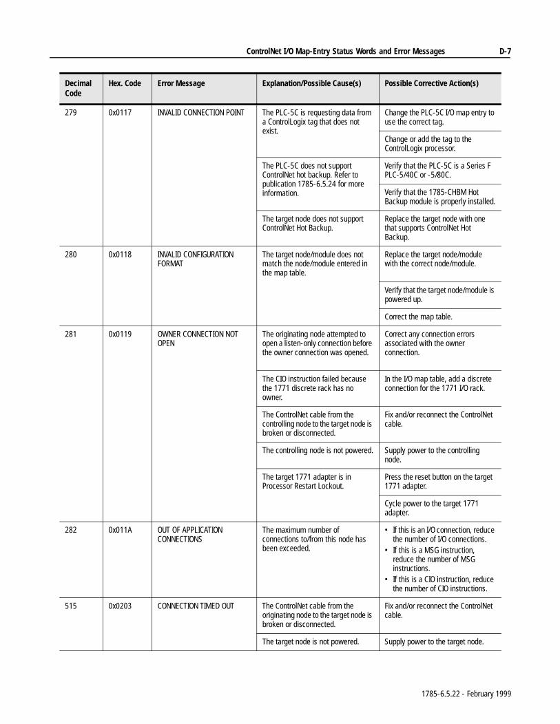
ControlNet I/O Map-Entry Status Words and Error Messages D-7
279 0x0117 INVALID CONNECTION POINT The PLC-5C is requesting data from a ControlLogix tag that does not exist.
Change the PLC-5C I/O map entry to use the correct tag.
Change or add the tag to the ControlLogix processor.
The PLC-5C does not support ControlNet hot backup. Refer to publication 1785-6.5.24 for more information.
Verify that the PLC-5C is a Series F PLC-5/40C or -5/80C.
Verify that the 1785-CHBM Hot Backup module is properly installed.
The target node does not support ControlNet Hot Backup.
Replace the target node with one that supports ControlNet Hot Backup.
280 0x0118 INVALID CONFIGURATION FORMAT
The target node/module does not match the node/module entered in the map table.
Replace the target node/module with the correct node/module.
Verify that the target node/module is powered up.
Correct the map table.
281 0x0119 OWNER CONNECTION NOT OPEN
The originating node attempted to open a listen-only connection before the owner connection was opened.
Correct any connection errors associated with the owner connection.
The CIO instruction failed because the 1771 discrete rack has no owner.
In the I/O map table, add a discrete connection for the 1771 I/O rack.
The ControlNet cable from the controlling node to the target node is broken or disconnected.
Fix and/or reconnect the ControlNet cable.
The controlling node is not powered. Supply power to the controlling node.
The target 1771 adapter is in Processor Restart Lockout.
Press the reset button on the target 1771 adapter.
Cycle power to the target 1771 adapter.
282 0x011A OUT OF APPLICATION CONNECTIONS
The maximum number of connections to/from this node has been exceeded.
• If this is an I/O connection, reduce the number of I/O connections.
• If this is a MSG instruction, reduce the number of MSG instructions.
• If this is a CIO instruction, reduce the number of CIO instructions.
515 0x0203 CONNECTION TIMED OUT The ControlNet cable from the originating node to the target node is broken or disconnected.
Fix and/or reconnect the ControlNet cable.
The target node is not powered. Supply power to the target node.
Decimal Code
Hex. Code Error Message Explanation/Possible Cause(s) Possible Corrective Action(s)
1785-6.5.22 - February 1999
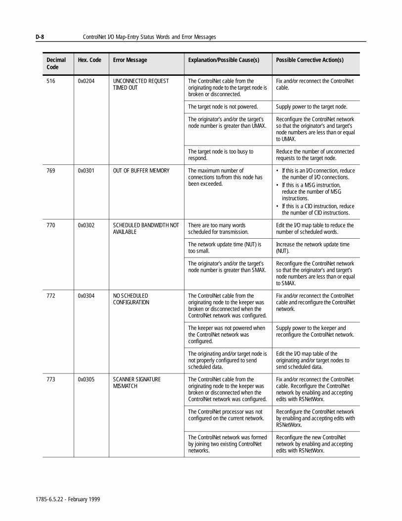
D-8 ControlNet I/O Map-Entry Status Words and Error Messages
516 0x0204 UNCONNECTED REQUEST TIMED OUT
The ControlNet cable from the originating node to the target node is broken or disconnected.
Fix and/or reconnect the ControlNet cable.
The target node is not powered. Supply power to the target node.
The originator’s and/or the target’s node number is greater than UMAX.
Reconfigure the ControlNet network so that the originator’s and target’s node numbers are less than or equal to UMAX.
The target node is too busy to respond.
Reduce the number of unconnected requests to the target node.
769 0x0301 OUT OF BUFFER MEMORY The maximum number of connections to/from this node has been exceeded.
• If this is an I/O connection, reduce the number of I/O connections.
• If this is a MSG instruction, reduce the number of MSG instructions.
• If this is a CIO instruction, reduce the number of CIO instructions.
770 0x0302 SCHEDULED BANDWIDTH NOT AVAILABLE
There are too many words scheduled for transmission.
Edit the I/O map table to reduce the number of scheduled words.
The network update time (NUT) is too small.
Increase the network update time (NUT).
The originator’s and/or the target’s node number is greater than SMAX.
Reconfigure the ControlNet network so that the originator’s and target’s node numbers are less than or equal to SMAX.
772 0x0304 NO SCHEDULED CONFIGURATION
The ControlNet cable from the originating node to the keeper was broken or disconnected when the ControlNet network was configured.
Fix and/or reconnect the ControlNet cable and reconfigure the ControlNet network.
The keeper was not powered when the ControlNet network was configured.
Supply power to the keeper and reconfigure the ControlNet network.
The originating and/or target node is not properly configured to send scheduled data.
Edit the I/O map table of the originating and/or target nodes to send scheduled data.
773 0x0305 SCANNER SIGNATURE MISMATCH
The ControlNet cable from the originating node to the keeper was broken or disconnected when the ControlNet network was configured.
Fix and/or reconnect the ControlNet cable. Reconfigure the ControlNet network by enabling and accepting edits with RSNetWorx.
The ControlNet processor was not configured on the current network.
Reconfigure the ControlNet network by enabling and accepting edits with RSNetWorx.
The ControlNet network was formed by joining two existing ControlNet networks.
Reconfigure the new ControlNet network by enabling and accepting edits with RSNetWorx.
Decimal Code
Hex. Code Error Message Explanation/Possible Cause(s) Possible Corrective Action(s)
1785-6.5.22 - February 1999
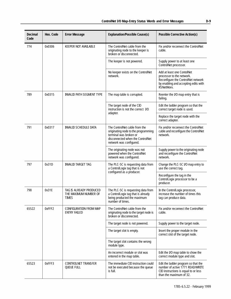
ControlNet I/O Map-Entry Status Words and Error Messages D-9
774 0x0306 KEEPER NOT AVAILABLE The ControlNet cable from the originating node to the keeper is broken or disconnected.
Fix and/or reconnect the ControlNet cable.
The keeper is not powered. Supply power to at least one ControlNet processor.
No keeper exists on the ControlNet network.
Add at least one ContolNet processor to the network. Reconfigure the ControlNet network by enabling and accepting edits with RSNetWorx.
789 0x0315 INVALID PATH SEGMENT TYPE The map table is corrupted. Reenter the I/O map entry that is failing.
The target node of the CIO instruction is not the correct I/O adapter.
Edit the ladder program so that the correct target node is used.
Replace the target node with the correct adapter.
791 0x0317 INVALID SCHEDULE DATA The ControlNet cable from the originating node to the programming terminal was broken or disconnected when the ControlNet network was configured.
Fix and/or reconnect the ControlNet cable and reconfigure the ControlNet network.
The originating node was not powered when the ControlNet network was configured.
Supply power to the originating node and reconfigure the ControlNet network.
797 0x31D INVALID TARGET TAG The PLC-5C is requesting data from a ControlLogix tag that is not configured as a producer.
Change the PLC-5C I/O map entry to use the correct tag.
Reconfigure the tag in the ControlLogix processor to be a producer.
798 0x31E TAG IS ALREADY PRODUCED THE MAXIMUM NUMBER OF TIMES
The PLC-5C is requesting data from a ControlLogix tag that is already being producted the maximum number of times.
In the ControlLogix processor, increase the number of times this tag can produce data.
65522 0xFFF2 CONFIGURATION FROM MAP ENTRY FAILED
The ControlNet cable from the originating node to the target node is broken or disconnected.
Fix and/or reconnect the ControlNet cable.
The target node is not powered. Supply power to the target node.
The target slot is empty. Insert the proper module in the correct slot of the target node.
The target slot contains the wrong module type.
An incorrect module or slot was entered in the map table.
Edit the I/O map table to show the correct module type and slot.
65523 0xFFF3 CONTROLNET TRANSFER QUEUE FULL
The immediate CIO instruction could not be executed because the queue is full.
Edit the ladder program so that the number of active 1771 READ/WRITE CIO instructions is equal to or less than the maximum of 32.
Decimal Code
Hex. Code Error Message Explanation/Possible Cause(s) Possible Corrective Action(s)
1785-6.5.22 - February 1999
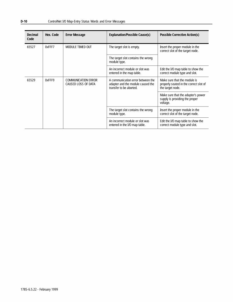
D-10 ControlNet I/O Map-Entry Status Words and Error Messages
65527 0xFFF7 MODULE TIMED OUT The target slot is empty. Insert the proper module in the correct slot of the target node.
The target slot contains the wrong module type.
An incorrect module or slot was entered in the map table.
Edit the I/O map table to show the correct module type and slot.
65529 0xFFF9 COMMUNICATION ERROR CAUSED LOSS OF DATA
A communication error between the adapter and the module caused the transfer to be aborted.
Make sure that the module is properly seated in the correct slot of the target node.
Make sure that the adapter’s power supply is providing the proper voltage.
The target slot contains the wrong module type.
Insert the proper module in the correct slot of the target node.
An incorrect module or slot was entered in the I/O map table.
Edit the I/O map table to show the correct module type and slot.
Decimal Code
Hex. Code Error Message Explanation/Possible Cause(s) Possible Corrective Action(s)
1785-6.5.22 - February 1999
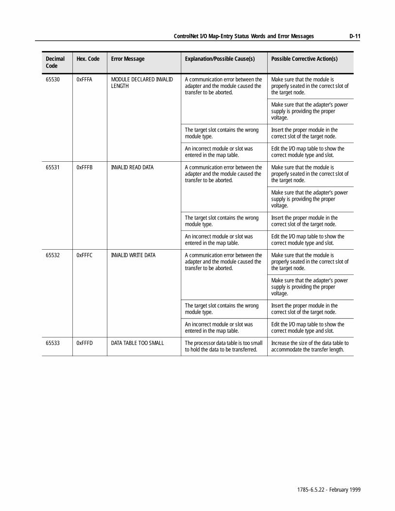
ControlNet I/O Map-Entry Status Words and Error Messages D-11
65530 0xFFFA MODULE DECLARED INVALID LENGTH
A communication error between the adapter and the module caused the transfer to be aborted.
Make sure that the module is properly seated in the correct slot of the target node.
Make sure that the adapter’s power supply is providing the proper voltage.
The target slot contains the wrong module type.
Insert the proper module in the correct slot of the target node.
An incorrect module or slot was entered in the map table.
Edit the I/O map table to show the correct module type and slot.
65531 0xFFFB INVALID READ DATA A communication error between the adapter and the module caused the transfer to be aborted.
Make sure that the module is properly seated in the correct slot of the target node.
Make sure that the adapter’s power supply is providing the proper voltage.
The target slot contains the wrong module type.
Insert the proper module in the correct slot of the target node.
An incorrect module or slot was entered in the map table.
Edit the I/O map table to show the correct module type and slot.
65532 0xFFFC INVALID WRITE DATA A communication error between the adapter and the module caused the transfer to be aborted.
Make sure that the module is properly seated in the correct slot of the target node.
Make sure that the adapter’s power supply is providing the proper voltage.
The target slot contains the wrong module type.
Insert the proper module in the correct slot of the target node.
An incorrect module or slot was entered in the map table.
Edit the I/O map table to show the correct module type and slot.
65533 0xFFFD DATA TABLE TOO SMALL The processor data table is too small to hold the data to be transferred.
Increase the size of the data table to accommodate the transfer length.
Decimal Code
Hex. Code Error Message Explanation/Possible Cause(s) Possible Corrective Action(s)
1785-6.5.22 - February 1999
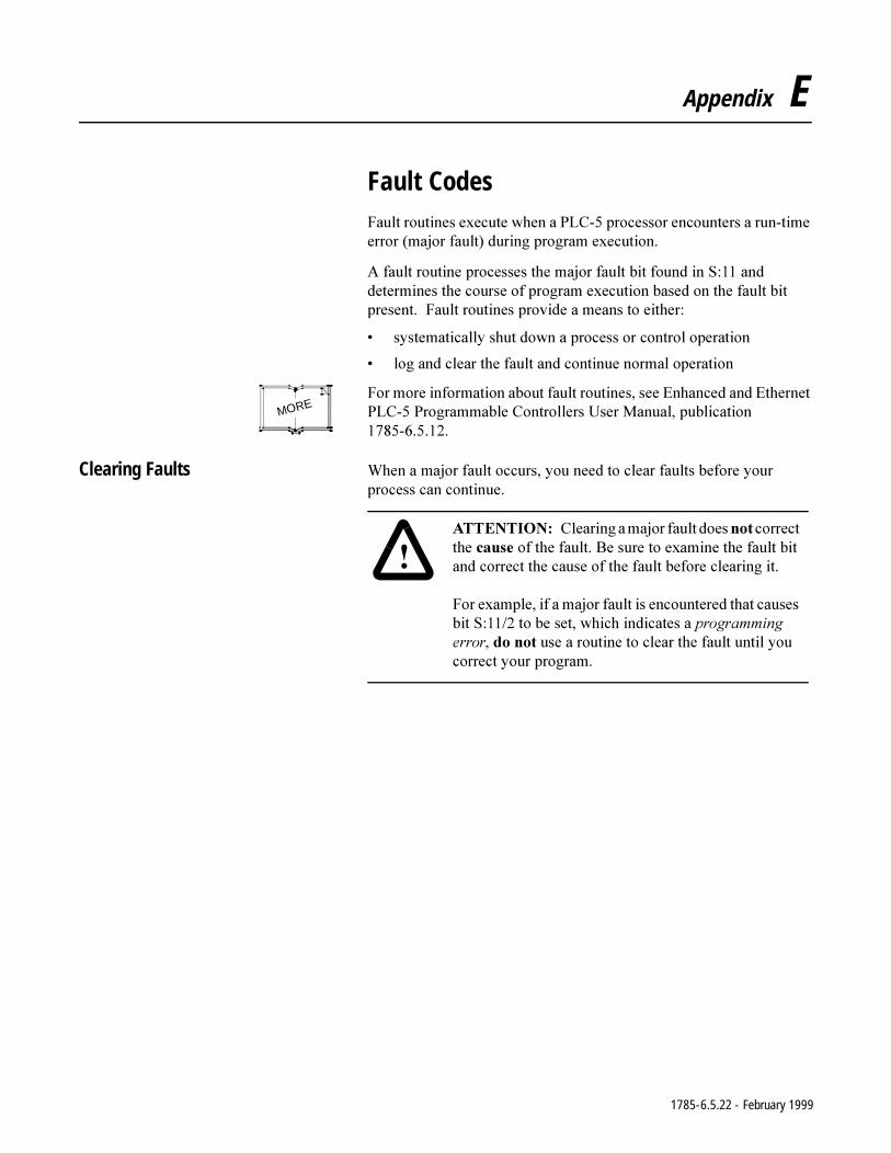
Appendix E
Fault Codes)DXOWURXWLQHVH[HFXWHZKHQD3/&SURFHVVRUHQFRXQWHUVDUXQWLPHHUURUPDMRUIDXOWGXULQJSURJUDPH[HFXWLRQ
$IDXOWURXWLQHSURFHVVHVWKHPDMRUIDXOWELWIRXQGLQ6DQGGHWHUPLQHVWKHFRXUVHRISURJUDPH[HFXWLRQEDVHGRQWKHIDXOWELWSUHVHQW)DXOWURXWLQHVSURYLGHDPHDQVWRHLWKHU
V\VWHPDWLFDOO\VKXWGRZQDSURFHVVRUFRQWURORSHUDWLRQ
ORJDQGFOHDUWKHIDXOWDQGFRQWLQXHQRUPDORSHUDWLRQ
)RUPRUHLQIRUPDWLRQDERXWIDXOWURXWLQHVVHH(QKDQFHGDQG(WKHUQHW3/&3URJUDPPDEOH&RQWUROOHUV8VHU0DQXDOSXEOLFDWLRQ
Clearing Faults :KHQDPDMRUIDXOWRFFXUV\RXQHHGWRFOHDUIDXOWVEHIRUH\RXUSURFHVVFDQFRQWLQXH
MORE
$77(17,21 &OHDULQJDPDMRUIDXOWGRHVQRWFRUUHFWWKHFDXVHRIWKHIDXOW%HVXUHWRH[DPLQHWKHIDXOWELWDQGFRUUHFWWKHFDXVHRIWKHIDXOWEHIRUHFOHDULQJLW
)RUH[DPSOHLIDPDMRUIDXOWLVHQFRXQWHUHGWKDWFDXVHVELW6WREHVHWZKLFKLQGLFDWHVDSURJUDPPLQJHUURUGRQRWXVHDURXWLQHWRFOHDUWKHIDXOWXQWLO\RXFRUUHFW\RXUSURJUDP
1785-6.5.22 - February 1999
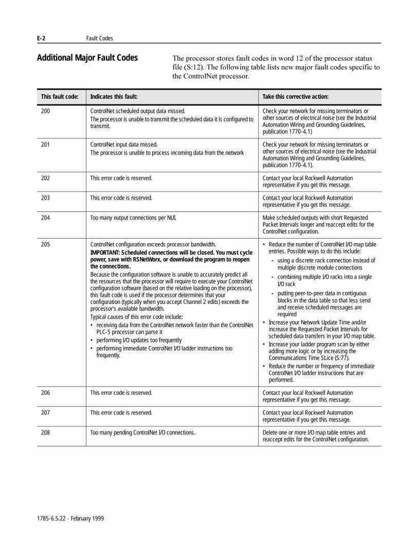
E-2 Fault Codes
Additional Major Fault Codes 7KHSURFHVVRUVWRUHVIDXOWFRGHVLQZRUGRIWKHSURFHVVRUVWDWXVILOH67KHIROORZLQJWDEOHOLVWVQHZPDMRUIDXOWFRGHVVSHFLILFWRWKH&RQWURO1HWSURFHVVRU
This fault code: Indicates this fault: Take this corrective action:
200 ControlNet scheduled output data missed.The processor is unable to transmit the scheduled data it is configured to transmit.
Check your network for missing terminators or other sources of electrical noise (see the Industrial Automation Wiring and Grounding Guidelines, publication 1770-4.1)
201 ControlNet input data missed.The processor is unable to process incoming data from the network
Check your network for missing terminators or other sources of electrical noise (see the Industrial Automation Wiring and Grounding Guidelines, publication 1770-4.1).
202 This error code is reserved. Contact your local Rockwell Automation representative if you get this message.
203 This error code is reserved. Contact your local Rockwell Automation representative if you get this message.
204 Too many output connections per NUI. Make scheduled outputs with short Requested Packet Intervals longer and reaccept edits for the ControlNet configuration.
205 ControlNet configuration exceeds processor bandwidth.IMPORTANT: Scheduled connections will be closed. You must cycle power, save with RSNetWorx, or download the program to reopen the connections.Because the configuration software is unable to accurately predict all the resources that the processor will require to execute your ControlNet configuration software (based on the relative loading on the processor), this fault code is used if the processor determines that your configuration (typically when you accept Channel 2 edits) exceeds the processor’s available bandwidth.Typical causes of this error code include: • receiving data from the ControlNet network faster than the ControlNet
PLC-5 processor can parse it• performing I/O updates too frequently• performing immediate ControlNet I/O ladder instructions too
frequently.
• Reduce the number of ControlNet I/O map table entries. Possible ways to do this include:
- using a discrete rack connection instead of multiple discrete module connections
- combining multiple I/O racks into a single I/O rack
- putting peer-to-peer data in contiguous blocks in the data table so that less send and receive scheduled messages are required
• Increase your Network Update Time and/or increase the Requested Packet Intervals for scheduled data transfers in your I/O map table.
• Increase your ladder program scan by either adding more logic or by increasing the Communications Time SLice (S:77).
• Reduce the number or frequency of immediate ControlNet I/O ladder instructions that are performed.
206 This error code is reserved. Contact your local Rockwell Automation representative if you get this message.
207 This error code is reserved. Contact your local Rockwell Automation representative if you get this message.
208 Too many pending ControlNet I/O connections. Delete one or more I/O map table entries and reaccept edits for the ControlNet configuration.
1785-6.5.22 - February 1999
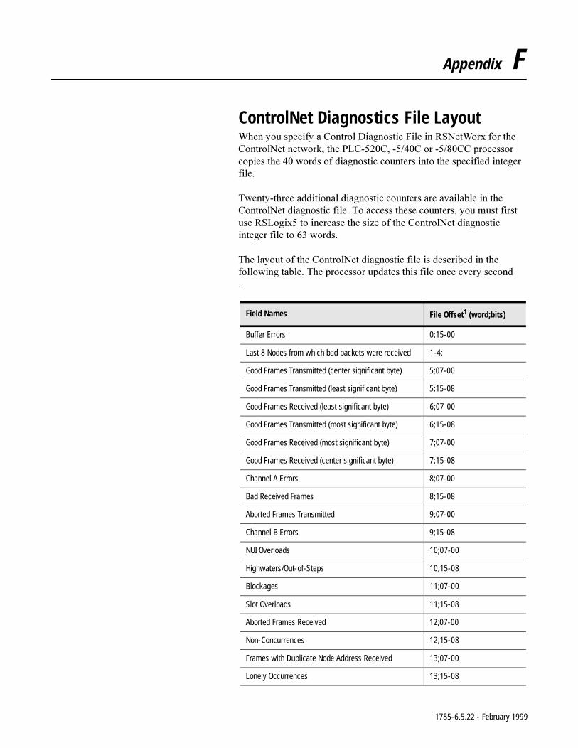
Appendix F
ControlNet Diagnostics File Layout:KHQ\RXVSHFLI\D&RQWURO'LDJQRVWLF)LOHLQ561HW:RU[IRUWKH&RQWURO1HWQHWZRUNWKH3/&&&RU&&SURFHVVRUFRSLHVWKHZRUGVRIGLDJQRVWLFFRXQWHUVLQWRWKHVSHFLILHGLQWHJHUILOH
7ZHQW\WKUHHDGGLWLRQDOGLDJQRVWLFFRXQWHUVDUHDYDLODEOHLQWKH&RQWURO1HWGLDJQRVWLFILOH7RDFFHVVWKHVHFRXQWHUV\RXPXVWILUVWXVH56/RJL[WRLQFUHDVHWKHVL]HRIWKH&RQWURO1HWGLDJQRVWLFLQWHJHUILOHWRZRUGV
7KHOD\RXWRIWKH&RQWURO1HWGLDJQRVWLFILOHLVGHVFULEHGLQWKHIROORZLQJWDEOH7KHSURFHVVRUXSGDWHVWKLVILOHRQFHHYHU\VHFRQG
Field Names File Offset1 (word;bits)
Buffer Errors 0;15-00
Last 8 Nodes from which bad packets were received 1-4;
Good Frames Transmitted (center significant byte) 5;07-00
Good Frames Transmitted (least significant byte) 5;15-08
Good Frames Received (least significant byte) 6;07-00
Good Frames Transmitted (most significant byte) 6;15-08
Good Frames Received (most significant byte) 7;07-00
Good Frames Received (center significant byte) 7;15-08
Channel A Errors 8;07-00
Bad Received Frames 8;15-08
Aborted Frames Transmitted 9;07-00
Channel B Errors 9;15-08
NUI Overloads 10;07-00
Highwaters/Out-of-Steps 10;15-08
Blockages 11;07-00
Slot Overloads 11;15-08
Aborted Frames Received 12;07-00
Non-Concurrences 12;15-08
Frames with Duplicate Node Address Received 13;07-00
Lonely Occurrences 13;15-08
1785-6.5.22 - February 1999
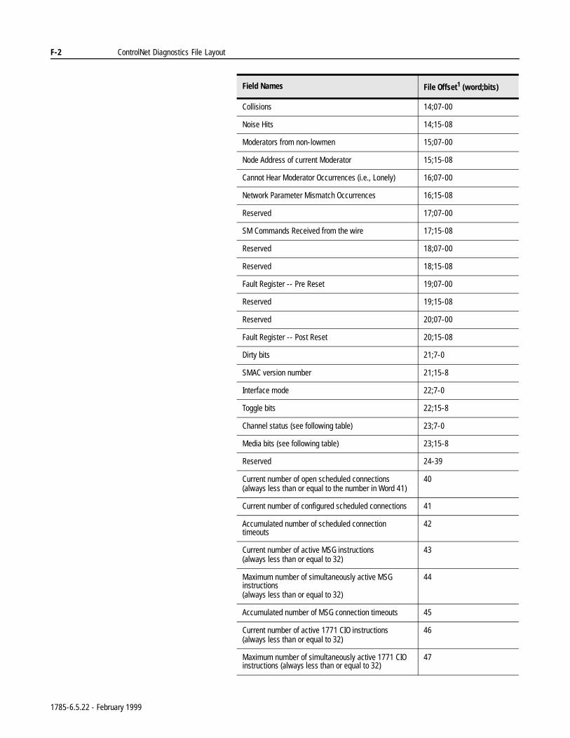
F-2 ControlNet Diagnostics File Layout
Collisions 14;07-00
Noise Hits 14;15-08
Moderators from non-lowmen 15;07-00
Node Address of current Moderator 15;15-08
Cannot Hear Moderator Occurrences (i.e., Lonely) 16;07-00
Network Parameter Mismatch Occurrences 16;15-08
Reserved 17;07-00
SM Commands Received from the wire 17;15-08
Reserved 18;07-00
Reserved 18;15-08
Fault Register -- Pre Reset 19;07-00
Reserved 19;15-08
Reserved 20;07-00
Fault Register -- Post Reset 20;15-08
Dirty bits 21;7-0
SMAC version number 21;15-8
Interface mode 22;7-0
Toggle bits 22;15-8
Channel status (see following table) 23;7-0
Media bits (see following table) 23;15-8
Reserved 24-39
Current number of open scheduled connections(always less than or equal to the number in Word 41)
40
Current number of configured scheduled connections 41
Accumulated number of scheduled connection timeouts
42
Current number of active MSG instructions(always less than or equal to 32)
43
Maximum number of simultaneously active MSG instructions(always less than or equal to 32)
44
Accumulated number of MSG connection timeouts 45
Current number of active 1771 CIO instructions(always less than or equal to 32)
46
Maximum number of simultaneously active 1771 CIO instructions (always less than or equal to 32)
47
Field Names File Offset1 (word;bits)
1785-6.5.22 - February 1999
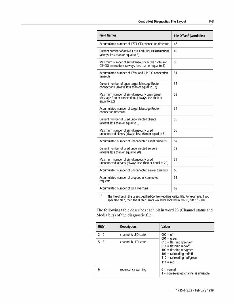
ControlNet Diagnostics File Layout F-3
7KHIROORZLQJWDEOHGHVFULEHVHDFKELWLQZRUG&KDQQHOVWDWXVDQG0HGLDELWVRIWKHGLDJQRVWLFILOH
Accumulated number of 1771 CIO connection timeouts 48
Current number of active 1794 and CIP CIO instructions(always less than or equal to 8)
49
Maximum number of simultaneously active 1794 and CIP CIO instructions (always less than or equal to 8)
50
Accumulated number of 1794 and CIP CIO connection timeouts
51
Current number of open target Message Router connections (always less than or equal to 32)
52
Maximum number of simultaneously open target Message Router connections (always less than or equal to 32)
53
Accumulated number of target Message Router connection timeouts
54
Current number of used unconnected clients(always less than or equal to 8)
55
Maximum number of simultaneously used unconnected clients (always less than or equal to 8)
56
Accumulated number of unconnected client timeouts 57
Current number of used unconnected servers(always less than or equal to 20)
58
Maximum number of simultaneously used unconnected servers (always less than or equal to 20)
59
Accumulated number of unconnected server timeouts 60
Accumulated number of dropped unconnected requests
61
Accumulated number of JITT overruns 62
1 The file offset in the user-specified ControlNet diagnostics file. For example, if you specified N12, then the Buffer Errors would be located in N12:0, bits 15 - 00.
Bit(s): Description: Values:
2 - 0 channel A LED state 000 = off001 = green010 = flashing green/off011 = flashing red/off100 = flashing red/green101 = railroading red/off110 = railroading red/green111 = red
5 - 3 channel B LED state
6 redundancy warning 0 = normal1 = non-selected channel is unusable
Field Names File Offset1 (word;bits)
1785-6.5.22 - February 1999
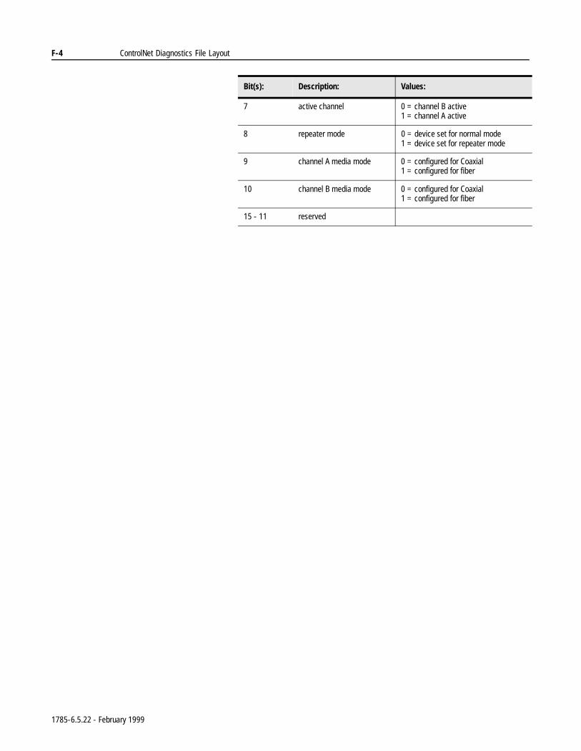
F-4 ControlNet Diagnostics File Layout
7 active channel 0 = channel B active1 = channel A active
8 repeater mode 0 = device set for normal mode1 = device set for repeater mode
9 channel A media mode 0 = configured for Coaxial1 = configured for fiber
10 channel B media mode 0 = configured for Coaxial1 = configured for fiber
15 - 11 reserved
Bit(s): Description: Values:
1785-6.5.22 - February 1999
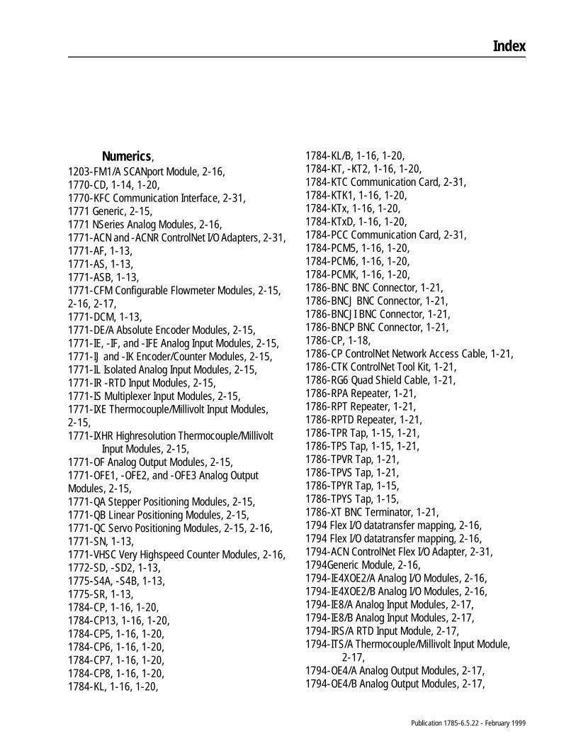
Index
Numerics, 1203-FM1/A SCANport Module, 2-16, 1770-CD, 1-14, 1-20, 1770-KFC Communication Interface, 2-31, 1771 Generic, 2-15, 1771 NSeries Analog Modules, 2-16, 1771-ACN and -ACNR ControlNet I/O Adapters, 2-31, 1771-AF, 1-13, 1771-AS, 1-13, 1771-ASB, 1-13, 1771-CFM Configurable Flowmeter Modules, 2-15,2-16, 2-17, 1771-DCM, 1-13, 1771-DE/A Absolute Encoder Modules, 2-15, 1771-IE, -IF, and -IFE Analog Input Modules, 2-15, 1771-IJ and -IK Encoder/Counter Modules, 2-15, 1771-IL Isolated Analog Input Modules, 2-15, 1771-IR -RTD Input Modules, 2-15, 1771-IS Multiplexer Input Modules, 2-15, 1771-IXE Thermocouple/Millivolt Input Modules,2-15, 1771-IXHR Highresolution Thermocouple/Millivolt
Input Modules, 2-15, 1771-OF Analog Output Modules, 2-15, 1771-OFE1, -OFE2, and -OFE3 Analog OutputModules, 2-15, 1771-QA Stepper Positioning Modules, 2-15, 1771-QB Linear Positioning Modules, 2-15, 1771-QC Servo Positioning Modules, 2-15, 2-16, 1771-SN, 1-13, 1771-VHSC Very Highspeed Counter Modules, 2-16, 1772-SD, -SD2, 1-13, 1775-S4A, -S4B, 1-13, 1775-SR, 1-13, 1784-CP, 1-16, 1-20, 1784-CP13, 1-16, 1-20, 1784-CP5, 1-16, 1-20, 1784-CP6, 1-16, 1-20, 1784-CP7, 1-16, 1-20, 1784-CP8, 1-16, 1-20, 1784-KL, 1-16, 1-20,
1784-KL/B, 1-16, 1-20, 1784-KT, -KT2, 1-16, 1-20, 1784-KTC Communication Card, 2-31, 1784-KTK1, 1-16, 1-20, 1784-KTx, 1-16, 1-20, 1784-KTxD, 1-16, 1-20, 1784-PCC Communication Card, 2-31, 1784-PCM5, 1-16, 1-20, 1784-PCM6, 1-16, 1-20, 1784-PCMK, 1-16, 1-20, 1786-BNC BNC Connector, 1-21, 1786-BNCJ BNC Connector, 1-21, 1786-BNCJI BNC Connector, 1-21, 1786-BNCP BNC Connector, 1-21, 1786-CP, 1-18, 1786-CP ControlNet Network Access Cable, 1-21, 1786-CTK ControlNet Tool Kit, 1-21, 1786-RG6 Quad Shield Cable, 1-21, 1786-RPA Repeater, 1-21, 1786-RPT Repeater, 1-21, 1786-RPTD Repeater, 1-21, 1786-TPR Tap, 1-15, 1-21, 1786-TPS Tap, 1-15, 1-21, 1786-TPVR Tap, 1-21, 1786-TPVS Tap, 1-21, 1786-TPYR Tap, 1-15, 1786-TPYS Tap, 1-15, 1786-XT BNC Terminator, 1-21, 1794 Flex I/O datatransfer mapping, 2-16, 1794 Flex I/O datatransfer mapping, 2-16, 1794-ACN ControlNet Flex I/O Adapter, 2-31, 1794Generic Module, 2-16, 1794-IE4XOE2/A Analog I/O Modules, 2-16, 1794-IE4XOE2/B Analog I/O Modules, 2-16, 1794-IE8/A Analog Input Modules, 2-17, 1794-IE8/B Analog Input Modules, 2-17, 1794-IRS/A RTD Input Module, 2-17, 1794-ITS/A Thermocouple/Millivolt Input Module,
2-17, 1794-OE4/A Analog Output Modules, 2-17, 1794-OE4/B Analog Output Modules, 2-17,
Publication 1785-6.5.22 - February 1999
I–2 Index
6008SQH1, SQH2, 1-13,
A, Actual Packet Interval,
description, 2-12, API, 2-12, automatic I/O mapping, 2-8, avoiding electrostatic damage, 1-3,
B, battery compartment,
location of, on PLC5/20C, 1-4, on PLC5/40C, 1-5,
battery life, 1-9,
C, cables,
remote I/O, 1-12, cabling, 1-20, Channel 1A, 2-33, Channel 1B, 2-33, CIOs, 2-3, Closing ControlNet communication, 4-3, communication,
time slice, B-13, communication connection, closing, 4-3, communication ports,
location of, on PLC5/20C, 1-4, on PLC5/40C, 1-5,
communication, option to close, 4-3, connecting a programming terminal, 1-16, connecting to a ControlNet network, 1-15, connection,
definition of, p-2, Conserving ControlNet resources, 4-3, ControlNet cabling, 1-20, ControlNet communication, closing, 4-3, ControlNet I/O,
error messages, D-4, features, 2-1, files configured with map,
Data Input File (DIF), 2-11, 2-13, Data Output File (DOF), 2-11, 2-13, Default Configuration File, 2-11,
I/O Status File, 2-11, I/O forcing, 2-6, immediate datatransfer operations, 2-7, map table,
creating, 2-8, entries, 2-8,
mapping scheduled data transfers, 2-8, maptable entry, 2-12, maptable entry fields, 2-11, 2-12, scheduled datatransfer operations, 2-2, 2-3, scheduled discrete I/O data transfer, 2-2, scheduled operations,
discrete I/O data transfer, 2-3, non-discrete I/O data transfer, 2-3, peer-to-peer communication, 2-3,
understanding, 2-1, unscheduled datatransfer operations, 2-3, unscheduled nondiscrete I/O data transfer, 2-3, unscheduled operations,
ControlNet I/O Transfer (CIO) instruction, description, C-1,
ControlNet I/O Transfer (CIO) instructions, description, 2-5, features, 2-5,
I/O transfer instructions, programming, 4-3,
immediate data I/O instructions, programming, 4-6,
ladderrung messages, 2-3, messaging from programming devices, 2-3, nondiscrete I/O data transfer, 2-5, nondiscrete I/O data transfers, 2-5,
description, C-1, features, C-1,
peer-to-peer messaging, 2-3, 2-6, peer-to-peer messaging instructions, 4-1,
programming, C-1, ControlNet I/O automatic mapping, 2-8, ControlNet I/O mapping,
automatic, 2-8, reserving rack space for remoteI/O linked racks
before mapping, 2-8, understanding, 2-8,
discrete I/O datatransfer mapping, 2-13, mapping data transfers, 2-10, non-discrete I/O datatransfer mapping, 2-13,
2-16,
Publication 1785-6.5.22 - February 1999
Index I–3
ControlNet I/O Transfer (CIO) instructions, 2-3, 2-5,4-3, C-1,
ControlNet immediate data I/O, instructions,
Immediate Data Input (IDI), C-2, Immediate Data Output (IDO), C-2,
process, C-2, ControlNet immediate data I/O instructions,
process, 2-8, ControlNet Immediate Data Input (IDI) instruction,
2-8, ControlNet Immediate Data Output (IDO) instruction,
2-8, ControlNet network,
definition of, p-2, locating additional information, p-4,
ControlNet Network Settings, fields, 2-12,
ControlNet PLC5/20C processor, 1-4, ControlNet PLC5/40C processor, 1-5, ControlNet processor,
configuring your ControlNet system, 3-1, installing, 1-1, planning to use, 2-1, programming your system, 4-1,
ControlNet system, cabling, 1-20, configuring, 3-1,
changing a 1794 I/O module’s fault action, 2-5, 4-4,
changing a 1794 I/O modules fault idleaction, 2-5, 4-4,
configuring nodes, 2-8, locating additional information, p-4, monitoring, 5-1, network maintenance, 2-4, network update cycle,
what happens in, 2-4, scheduled operations, 2-4, selecting devices to connect, 2-31, troubleshooting, 5-1, unscheduled operations, 2-4, using ControlNet PLC-5 processors in, 2-31,
ControlNet, conserving resources, 4-3,
D, Data Input File,
description, 2-11, 2-13, Data Output File,
description, 2-11, 2-13, Default Configuration File,
description, 2-11, DIF, 2-11, 2-13, discrete I/O data transfer,
definition of, p-2, description, 2-3,
discrete I/O data-transfer mapping, 2-13, disposing of the processor battery, 1-9, DOF, 2-11, 2-13, drop cable,
definition of, p-2,
E, error codes, D-4, Expected Network Packet Time,
1771 non-discrete I/O datatransfer mapping, 2-16, 2-17,
F, files,
configuration, 2-12, configured with I/O map for scheduled I/O usage,
2-11, Data Input, 2-11, 2-13, Data Output, 2-11, 2-13, Default Configuration, 2-11, I/O Status, 2-11, 2-12, 2-34, D-1, I/O status, 2-11, input, 2-12, input image, 2-2, 2-12, output, 2-12, output image, 2-2, 2-12, processor status, B-1,
frame, definition of, p-2,
front panel, PLC-5/20C processor, 1-4, PLC-5/40C processor, 1-5,
G, global status bits,
racks 07, B-2, racks 1017, B-11,
Publication 1785-6.5.22 - February 1999
I–4 Index
H, handling the processor, 1-3,
I, I/O,
ControlNet, 2-1, automatic mapping, 2-8, discrete I/O data-transfer mapping, 2-13, files configured with map,
Data Input File (DIF), 2-11, 2-13, Data Output File (DOF), 2-11, 2-13, Default Configuration File, 2-11, I/O Status File, 2-11,
I/O forcing, 2-6, immediate data transfer, 2-7, map table,
creating, 2-8, entries, 2-8, maximum number of entries, 2-10,
mapping, 2-8, mapping data transfers, 2-10, map-table entry, 2-12, map-table entry fields, 2-11, 2-12, non-discrete I/O datatransfer mapping, 2-13,
2-16, reserving rack space for remoteI/O linked
racks before mapping, 2-8, scheduled data transfer, 2-2, scheduled discrete I/O data transfer, 2-2, scheduled operations,
discrete I/O data transfer, 2-3, non-discrete I/O data transfer, 2-3, peer-to-peer communication, 2-3,
unscheduled, I/O data-transfer instructions, 4-3, immediate data I/O instructions, 4-6, Message instruction, 2-6, 4-1, C-1, non-discrete I/O data transfers, 2-5, C-1, non-discrete I/O data-transfer instruc-
tions, 4-3, unscheduled data transfer, 2-3, unscheduled nondiscrete I/O data transfer,
2-3, unscheduled operations,
messaging from programming devices,2-3,
non-discrete I/O data transfer, 2-3, peer-to-peer messaging, 2-3,
I/O forcing, 2-6, I/O map table,
definition of, p-2, I/O mapentry status words, D-1, I/O status indicator, 5-3, IDI, 2-8, IDO, 2-8, IIN, 2-8, Immediate Data Input (IDI) instruction, C-2, Immediate Data Output (IDO) instruction, C-2, immediate data-transfer operations, 2-7, immediate I/O,
process, 2-8, Immediate Input (IIN) instruction, 2-8, Immediate Output (IOT) instruction, 2-8, indicators,
PLC5/20C, 1-4, PLC5/40C, 1-5,
installing keying bands for the processor, 1-7, installing the processor battery, 1-8, installing your processor,
checking your processor package, 1-2, connecting a programming terminal, 1-16,
ControlNet connection, 1-18, DH+ connection, 1-16, serial channel, 1-17,
connecting to a ControlNet network, 1-15, disposing of the battery, 1-9, handling the processor, 1-3, identifying the components of the processor, 1-4, installing a DH+ link, 1-14, installing a remote I/O link, 1-12, installing keying bands for the processor, 1-7, installing the battery, 1-8, installing the processor in the chassis, 1-12, locating additional information, 1-1, preparing for, 1-2, removing the processor from the chassis, 1-12, selecting cables,
ControlNet cables, 1-20, DH+ programming, 1-20, remote I/O, 1-20, serial, 1-19,
selecting the ControlNet network address, 1-11, selecting the DH+ station address of Channel 1A,
Publication 1785-6.5.22 - February 1999
Index I–5
1-10, setting the I/O chassis backplane switches, 1-6, setting the I/O chassis configuration plug, 1-7, specifying the serial interface of Channel 0, 1-11,
instructions, ControlNet I/O Transfer (CIO), 2-5, C-1,
how to use, 4-3, when to use, 2-16, 2-34,
ControlNet Immediate Data Input (IDI), 2-8, C-2, how to use, 4-6,
ControlNet Immediate Data Output (IDO), 2-8, C-2,
how to use, 4-6, ControlNet Message (MSG),
how to use, 4-1, Immediate Input (IIN), 2-8, Immediate Output (IOT), 2-8, Message (MSG), 2-6,
how to use, C-1, when to use, 2-17,
IOT, 2-8,
K, keyswitch,
location of, on PLC-5/20C, 1-4, on PLC-5/40C, 1-5,
L, ladder-rung messaging, 2-3, link,
definition of, p-2,
M, map table, 2-8, map-table entries, 2-8, 2-11, map-table entry, p-2, memory-module space, 1-4, 1-5, Message instructions, 2-3, 2-6, 4-1, C-1, MSGs, 2-3, multicast, 2-20,
N, NAP, p-2, Network Access Port,
definition of, p-2,
when to use, 1-18, network address,
definition of, p-2, Network Update Interval, 2-4,
definition of, p-2, Network Update Time,
definition of, p-2, node,
definition of, p-2, non-discrete I/O data transfer, p-3, 2-3, non-discrete I/O datatransfer mapping, 2-14, 2-15, nonredundant media, 1-15, NUI, p-2, 2-4, NUT, p-2,
O, Option to Close Communication, 4-3, owner,
definition of, p-3,
P, PCMCIA Communication Card, 2-31, Peer In, 2-17, Peer Out, 2-17, PLC-5 processors, p-4, PLC-5 programming software, p-4, Process Control Sample Complete, 2-18, processor,
front panel, PLC5/20C, 1-4, PLC5/40C, 1-5,
processor status file, B-1, layout, B-1,
processor-resident local I/O, 2-9, programming a processor,
through Channel 0, 1-17, programming terminal,
connecting, 1-16,
R, rack control bits,
racks 07, B-11, racks 1017, B-12,
redundant media, 1-15, definition of, p-3,
remote I/O,
Publication 1785-6.5.22 - February 1999
I–6 Index
cable lengths, 1-12, nonControlNet, 2-9,
remote-I/O immediate I/O transfers, 2-7, 4-8, repeater,
definition of, p-3, replacing a non-ControlNet remote I/O network with
a ControlNet network, 2-8, 2-33, 2-34, replacing the processor battery, 1-9, Requested Packet Interval,
1771 non-discrete I/O datatransfer mapping, 2-17,
1794 Flex I/O data-transfer mapping, 2-17, description, 2-11,
RPI, 2-11,
S, scheduled data-transfer operations, 2-2, 2-3, scheduled discrete I/O data transfer,
process, 2-2, scheduled peer-to-peer communication, 2-3, scheduled peer-to-peer communications, 2-17, scheduled peer-to-peer communications mapping,
2-17, scheduled transfers,
definition of, p-3, screens,
Instruction Entry for ControlNet I/O Transfer Block, 4-3,
Instruction Entry for Message Block, 4-1, segment,
definition of, p-3, terminating, 1-15,
Selectable Timed Interrupts (STIs), using with ControlNet system, 4-9,
selecting the DH+ station address of Channel 1A, 1-10,
setting the I/O chassis backplane switches, 1-6, addressing switches, 1-6, EEPROMtransfer switches, 1-6, last-state switch, 1-6, processor memoryprotection switch, 1-6,
setting the I/O chassis configuration plug, 1-7, specifying the serial interface of Channel 0, 1-11, status,
layout for the processor, B-1, Status File, D-1,
I/O,
description, 2-11, status file,
processor, B-1, status indicators,
location of, on PLC5/20C, 1-4, on PLC5/40C, 1-5,
using, 5-1, 5-3, status words,
I/O map entry, D-1,
T, tap, 1-18,
connecting, 1-15, definition of, p-3, using, 1-15,
terminator, definition of, p-3,
trunk cable, definition of, p-3,
trunk-cable section, p-3,
U, unscheduled data-transfer operations, 2-3, unscheduled non-discrete I/O data transfer, 2-3, unscheduled transfers,
definition of, p-3, user control bits,
processor status file, B-11, using ControlNet I/O Transfer (CIO) instructions, 4-3, using ControlNet Immediate Data I/O instructions,
4-6, using ControlNet Message (MSG) instructions, 4-1, using the ControlNet status indicators, 5-3, using the general status indicators, 5-1, using this manual,
conventions used, p-3, intended audience for, p-1, introduction to, p-1, recommended preparation for, p-1,
Publication 1785-6.5.22 - February 1999
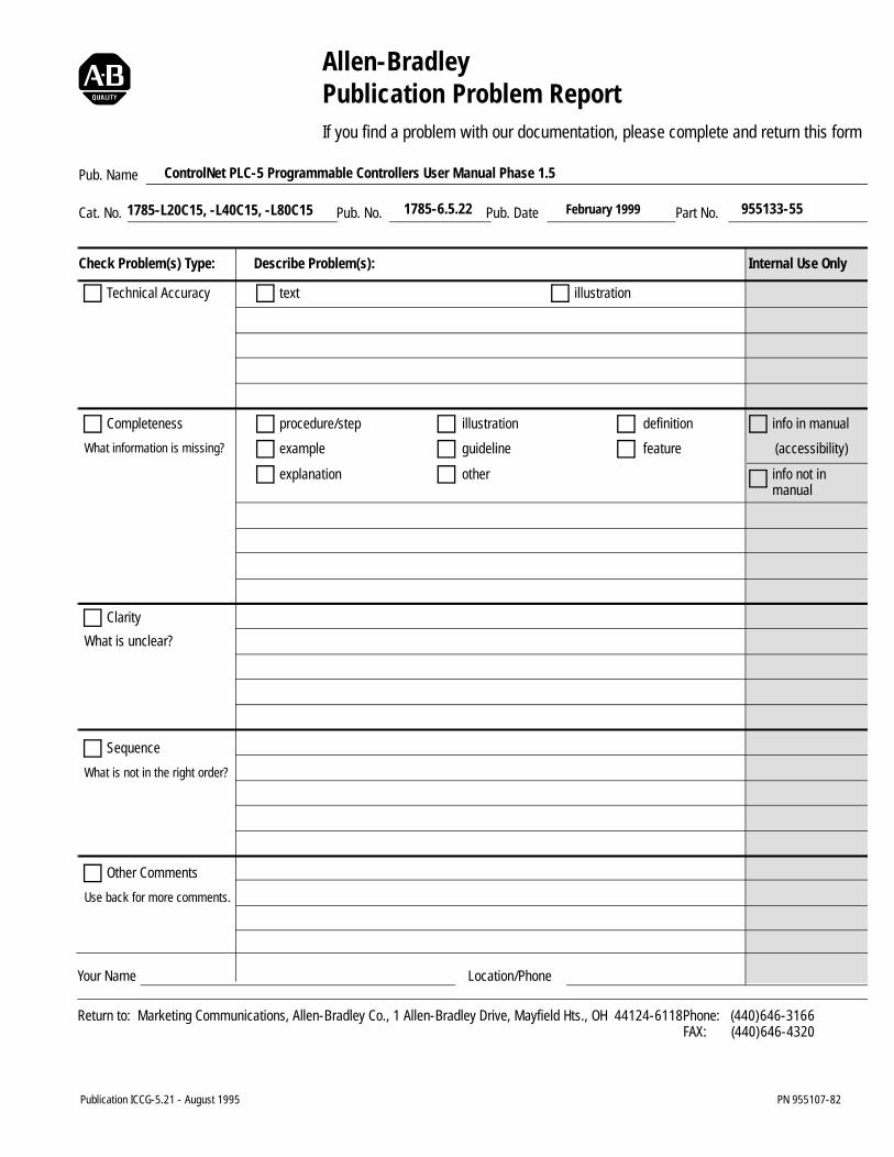
Allen-BradleyPublication Problem ReportIf you find a problem with our documentation, please complete and return this form
Publication ICCG-5.21 - August 1995 PN 955107-82
Pub. Name
Cat. No. Pub. No. Pub. Date Part No.
Check Problem(s) Type: Describe Problem(s): Internal Use Only
procedure/step
example
explanation
illustration
guideline
other
definition
feature
info in manual
(accessibility)
info not inmanual
text illustrationTechnical Accuracy
Completeness
What information is missing?
Clarity
Sequence
What is not in the right order?
What is unclear?
Other Comments
Use back for more comments.
Your Name Location/Phone
Return to: Marketing Communications, Allen-Bradley Co., 1 Allen-Bradley Drive, Mayfield Hts., OH 44124-6118Phone: (440)646-3166FAX: (440)646-4320
ControlNet PLC-5 Programmable Controllers User Manual Phase 1.5
1785-L20C15, -L40C15, -L80C15 1785-6.5.22 955133-55February 1999

Other Comments
PLEASE FOLD HERE
123267$*(1(&(66$5<,)0$,/(',17+(
81,7('67$7(6
BUSINESS REPLY MAILFIRST-CLASS MAIL PERMIT NO. 18235 CLEVELAND OH
POSTAGE WILL BE PAID BY THE ADDRESSEE
$//(1%5$'/(<'50$<),(/'+(,*+762+
3/($6(5(029(
PLEASE FASTEN HERE (DO NOT STAPLE)

1785-6.5.22 - February 1999 PN 955133-55Supersedes Publication 1785-6.5.22 - June 1997 1999 Rockwell International. All Rights Reserved. Printed in USA