
Cummins Hybrid White Paper.ppt - UNECE · PDF fileMain points of Cummins hybrid white paper...
31
Cummins Hybrid Certification White P O i Paper Overview
Transcript of Cummins Hybrid White Paper.ppt - UNECE · PDF fileMain points of Cummins hybrid white paper...

Cummins Hybrid yCertification White
P O iPaper Overview
HANSTEI
Schreibmaschinentext
HANSTEI
Schreibmaschinentext
GRPE/HDH-03-06
HANSTEI
Schreibmaschinentext

Cummins Hybrid Certification White Paperte ape
Evaluation and certification of hybrids presents unique h llchallenges– Regulatory development efforts in US, EU, and China– One prominent proposal is HILS
Cummins hybrid white paper proposes concept for h b id tifi tihybrid certification– Proposal was developed in response to EPA’s CO2 regulation
development, but may be applicable to EU and China– Hybrid concept builds on HD CO2 regulatory framework
described in Cummins CO2 white paper
2 2
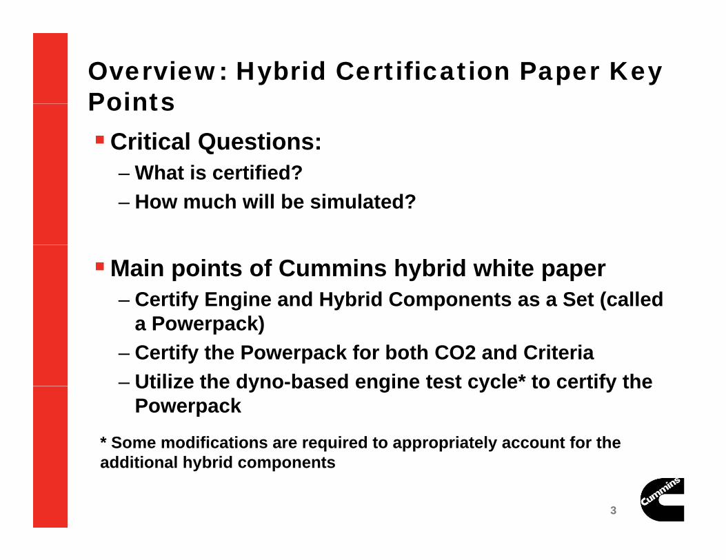
Overview: Hybrid Certification Paper Key PointsPointsCritical Questions:
– What is certified?– What is certified?– How much will be simulated?
Main points of Cummins hybrid white paper– Certify Engine and Hybrid Components as a Set (called
a Powerpack)– Certify the Powerpack for both CO2 and Criteria– Utilize the dyno-based engine test cycle* to certify theUtilize the dyno based engine test cycle to certify the
Powerpack
* Some modifications are required to appropriately account for the dditi l h b id t
3 3
additional hybrid components
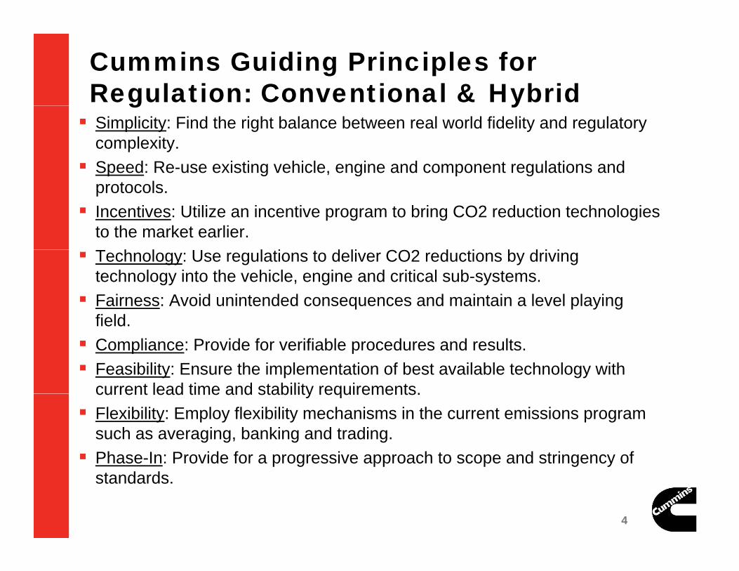
Cummins Guiding Principles for Regulation: Conventional & Hybridg y Simplicity: Find the right balance between real world fidelity and regulatory
complexity. Speed: Re-use existing vehicle, engine and component regulations and
protocols. Incentives: Utilize an incentive program to bring CO2 reduction technologies
to the market earlier.T h l U l i d li CO2 d i b d i i Technology: Use regulations to deliver CO2 reductions by driving technology into the vehicle, engine and critical sub-systems. Fairness: Avoid unintended consequences and maintain a level playing
fieldfield. Compliance: Provide for verifiable procedures and results. Feasibility: Ensure the implementation of best available technology with
current lead time and stability requirements.current lead time and stability requirements. Flexibility: Employ flexibility mechanisms in the current emissions program
such as averaging, banking and trading. Phase-In: Provide for a progressive approach to scope and stringency of
4 4
p g pp p g ystandards.
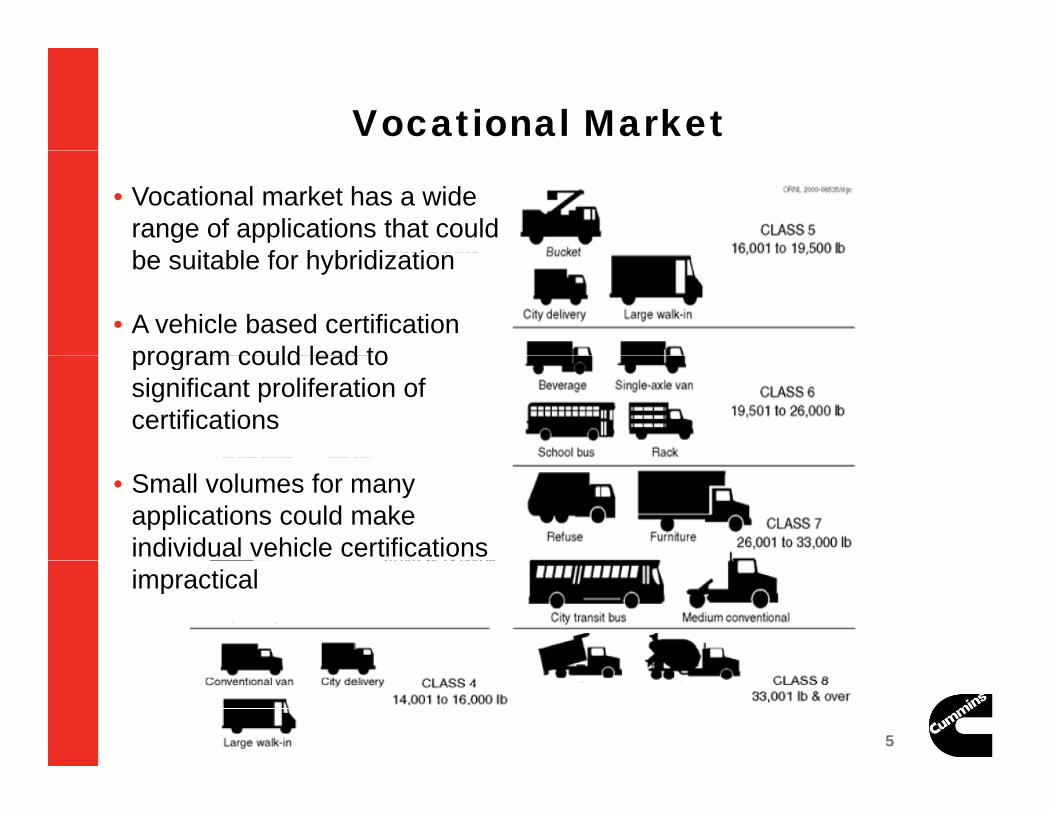
Vocational Market
• Vocational market has a wide range of applications that could b it bl f h b idi tibe suitable for hybridization
• A vehicle based certification program could lead toprogram could lead to significant proliferation of certifications
• Small volumes for many applications could make individual vehicle certifications impractical
5 5
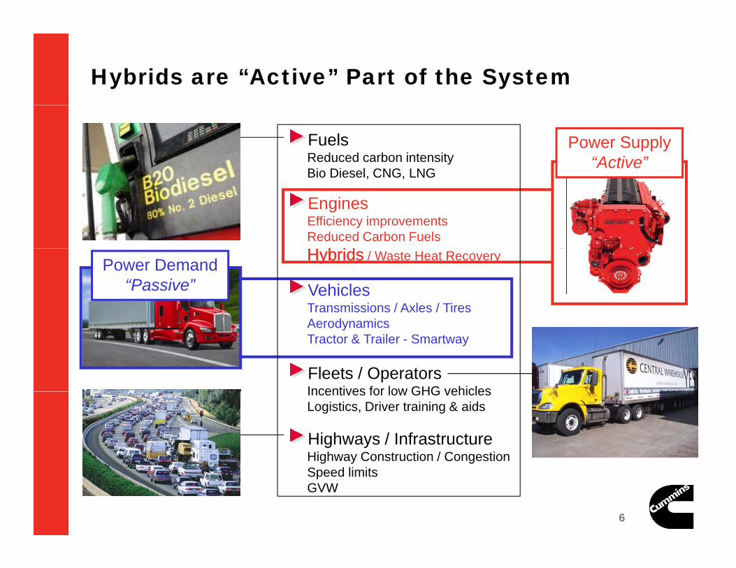
Hybrids are “Active” Part of the System
FuelsReduced carbon intensityBio Diesel, CNG, LNG
Power Supply“Active”
Bio Diesel, CNG, LNG
EnginesEfficiency improvementsReduced Carbon FuelsH b idH b id
VehiclesTransmissions / Axles / TiresA d i
HybridsHybrids / Waste Heat Recovery Power Demand“Passive”
AerodynamicsTractor & Trailer - Smartway
Fleets / OperatorsIncentives for low GHG vehicles
Highways / InfrastructureHighway Construction / Congestion
Incentives for low GHG vehiclesLogistics, Driver training & aids
6 6
g y gSpeed limitsGVW
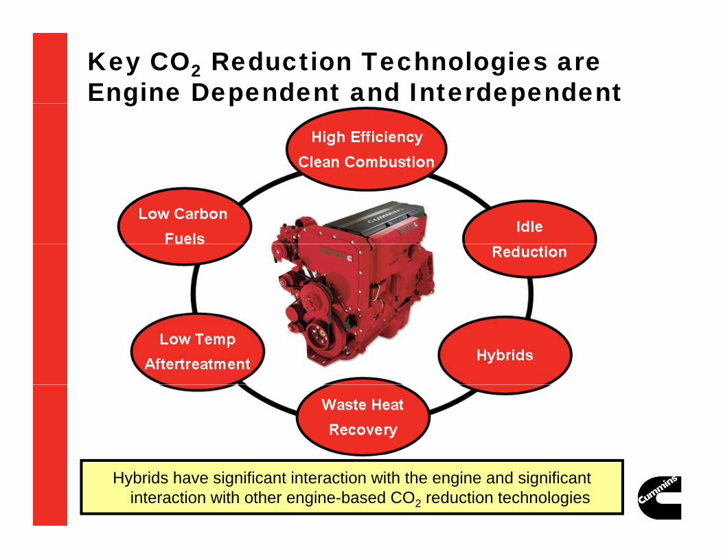
Key CO2 Reduction Technologies are Engine Dependent and Interdependentg p p
7 7
Hybrids have significant interaction with the engine and significant interaction with other engine-based CO2 reduction technologies

Hybrid CO2 Reduction Results from the Fact that the Engines in Hybrid Systems Operate
Differently than Conventional Diesel Engines
Conventional vs HybridHybrid Decouples Engine Power from Vehicle Power Reduced Cycle Work (from
Regenerative Braking)
St t / St O ti600
800
1000
(Nm
)
BaseHybrid
Start / Stop Operation
Increased Average Load
EngineStart/Stop
200
400
600
Eng
ine
Torq
ue
Opportunity to Manage Transient Load & Exhaust Temperatures640 645 650 655 660 665 670
0
time
The amount of CO2 is dependent upon the engine and upon the interaction of key components within the Hybrid Power Pack:
8 8
Hybrid Should be certified for both criteria and CO2 together.

Decoupling Engine Power from Vehicle Power Could Have Unintended Consequences Existing engine dyno cert assumes engine power matches vehicle
power. If hybrid decouples engine power from vehicle power, FTP cycle no
l i t f h b id i tifi tilonger appropriate for hybrid engine certification. Mis-match between certification & real world operation could lead to
higher criteria emissions, and less than optimal CO2 emissions reductionreduction.
mis
sion
s Existing Cert:Potential In-Use
C it i Li it
Existing Cert:Cert Result
Target Achieved with
Appropriate CertCrit
eria
Em Criteria Limit
9 9
Appropriate Cert
CO2 Emissions
C

Hybrid with Engine Certified Over Traditional FTP may Produce Higher Criteria EmissionsFTP may Produce Higher Criteria Emissions
DOE / NREL chassis test evaluation of hybrid P&D vehicle CO2 & criteria emissions
Eaton hybrid system
P100 van P100 van
CILCC Cycle
In this case hybridization resulted in lower PM emissions,
10 10
In this case hybridization resulted in lower PM emissions,but higher NOx emissions.

Hybrid should be Certified Jointly for Both Criteria and CO2 EmissionsCriteria and CO2 Emissions
on
)
Ensure real world critieria emissions equivalent to conventional
onsu
mpt
iopr
ovem
ent
Maximize opportunities for CO2 reduction
Allow for future technology development
~ 25% (CurrentSystems)
Fuel
Co
(% Im
p
gy(engine electrification & integration with hybrid system)
Alignment of CO2 & criteria certification is consistent with CO2 regulatory concepts for conventional powertrains.
Alignment of CO2 & criteria cert can enable 5-10% additional CO2 reduction that is not available today
11 11
reduction, that is not available todayGreater optimization can also reduce engine hardware cost and
improve reliability of system

Hybrid Certification Should Build on Existing Engine Certification
Existing FTP transient engine dyno test accurately describes hi l i t f id f ti lvehicle power requirements for a wide range of vocational
applications Significant industry experience with FTP procedures and protocols
Conventional Certification
Dyno• Use the normalized engine form of the cycle• Engine torque curve defines actual speed and torque for
Emissions
Work
EngineFuel
actual speed and torque for certification test• Emissions: g/hp-hr• Integrate only positive work (motoring work not included)
Work
Motor
12 12

Hybrid Certification of Pre-Transmission Hybrids Pre-transmission powerpack could utilize existing procedures and
protocols with minor modifications For many hybrid systems this approach would allow hardware
evaluation of engine, motor, battery, etc. One certification, many applications
Uses same simplifying assumptions as conventional certifications
Allow comparative performance evaluation with conventional
DEmissionsHybrid Certification:
Pre-Transmission Hybrid These are actual t ( t
p pengine
Motor /EngineFuel
Dyno
Work
Pre-Transmission Hybrid components (not simulated)• Use the normalized engine form
of the cycle(s)• Pre-transmission system torque
curve defines actual speed andGenEngine
Clutch
PowerMotor
(Regen)
curve defines actual speed and torque for certification test
• Emissions: g/hp-hr• Allow capture of energy during
“motoring” portions of FTPCount only positive work (as with
13 13
Battery PowerElec.
(Regen)• Count only positive work (as with conventional engines)

Post-Transmission Power Pack Certification Pre-transmission powerpack certification not viable for all hybrid p p y
architectures Post-transmission powerpack certification would work for series and other
transmission integrated hybrid systems
Hybrid Certification: Post-Transmission Option
Cycle based on FTP would allow comparative evaluation with conventional and pre-trans hybrid
U li d t
DEmissions
Hybrid Certification: Post-Transmission Option
These are actual t ( t
• Use normalized post-transmission test cycle(s)
• Post-transmission system torque curve
Motor /EngineFuel
Dyno
Work
components (not simulated)
Trans
y qdefines actual speed and torque for certification test
• Emissions: g/hp-hr• Allow capture of
GenEngine
Clutch
PowerMotor
(Regen)
Trans• Allow capture of energy during braking portions of cycle
• Count only positive
14 14
Battery PowerElec.
(Regen)work (as with conventional engines)

Powerpack and HILS
HILS very attractive, but presents some challenges– Development of models for some hybrid components (batteries)
Verification of compliance– Verification of compliance– Test cycle selection, standards for new cycles, and comparison with
conventional certification results
Powerpack is a form of HILS– Aero, rolling resistance, wheels, differential (+transmission in pre-
trans option) all simulated.
Advantages of powerpack concept Advantages of powerpack concept– Certifying powerpack would reduce proliferation– Inclusion of criteria emissions and CO2 allows maximum optimization
Inclusion of hybrid HW enables fast implementation
15 15
– Inclusion of hybrid HW enables fast implementation

Summary
Cummins hybrid white paper– Certify powerpack– Test all hybrid components – Certify for both criteria emissions and CO2– Build on existing experience with engine dyno based g p g y
certification
Questions:– Would powerpack approach be applicable to EU or China?– Is powerpack approach compatible with HILS?– Is powerpack approach compatible with HILS?
16 16
Appendix: Limiting of regen brakingLimiting of regen braking
17 17
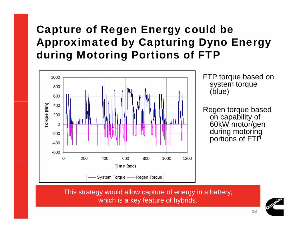
Capture of Regen Energy could be Approximated by Capturing Dyno Energy Approximated by Capturing Dyno Energy during Motoring Portions of FTP
FTP torque based on system torque (blue)
600
800
1000
Regen torque based on capability of 60kW motor/gen during motoring
0
200
400
Torq
ue (N
m)
during motoring portions of FTP
-600
-400
-200
0 200 400 600 800 1000 1200
Time (sec)
System Torque Regen Torque
18 18
This strategy would allow capture of energy in a battery,which is a key feature of hybrids.
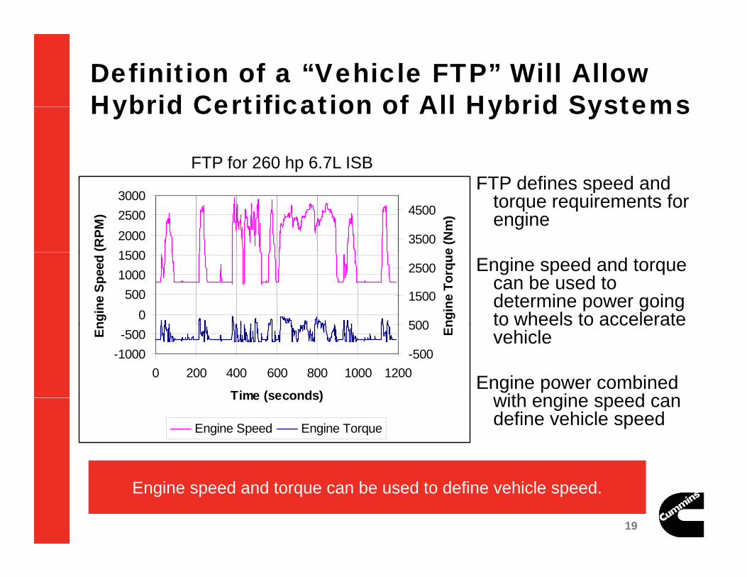
Definition of a “Vehicle FTP” Will Allow Hybrid Certification of All Hybrid SystemsHybrid Certification of All Hybrid Systems
FTP defines speed andFTP for 260 hp 6.7L ISB
FTP defines speed and torque requirements for engine
1500200025003000
(RPM
)
3500
4500
e (N
m)
Engine speed and torque can be used to determine power going to wheels to accelerate0
50010001500
ngin
e Sp
eed
500
1500
2500
ngin
e To
rque
to wheels to accelerate vehicle
Engine power combined with engine speed can
-1000-500
0 200 400 600 800 1000 1200
Time (seconds)
En
-500
500 En
with engine speed can define vehicle speed
Time (seconds)
Engine Speed Engine Torque
19 19
Engine speed and torque can be used to define vehicle speed.

Definition of a Post Transmission FTP Will Allow Hybrid Certification of All Hybrid SystemsHybrid Certification of All Hybrid SystemsFTP defines speed and torque requirements for engineAcceleration: If engine torque positive, engine speed and torque can be
used to determine power going to wheels to accelerate vehicleused to determine power going to wheels to accelerate vehicle
PMgfVAreaC
onAcceleratiMassForceForce
accessory
VehLoadEngine
2***1
*
Deceleration: Engine torque negativeM
VMgfVAreaC
MVP
Accel
yrollingaird
Eng
***
2
g q g– If engine speed ~ constant assume coasting and calculate deceleration
based on motoring engine torque.– If engine speed decelerates quickly, assume braking.
• At > 15 mph calculate vehicle deceleration based on engineAt > 15 mph, calculate vehicle deceleration based on engine deceleration
• At < 15 mph, decelerate vehicle at 1.5 m/s2
20 20
Engine speed and torque can be used to define vehicle speed.

Definition of a Post Transmission FTP Will Allow Hybrid Certification of All Hybrid Systems
70
80Vehicle FTP Cycle
ISC8.3L, 24947.5kg Beverage TractorISB6.7L, 11793.4kg P&DISB4.5L, 12000kg P&DISB3.8L, 12000kg P&D
“Average” cycle could be defined based on
l l d
50
60
h)
g
calculated vehicle speed for a range of engines &
hi l
30
40
Veh
icle
Spe
ed(m
ph vehicles.
Vehicle speed could also be
20
30 could also be used to calculate maximum regen energy available to ensure
0 200 400 600 800 1000 12000
10
Time(sec)
to ensure powerpack energy capture is realistic.
21 21
Vehicle speed vs. time will be consistent with FTP in terms of engine power requirements.
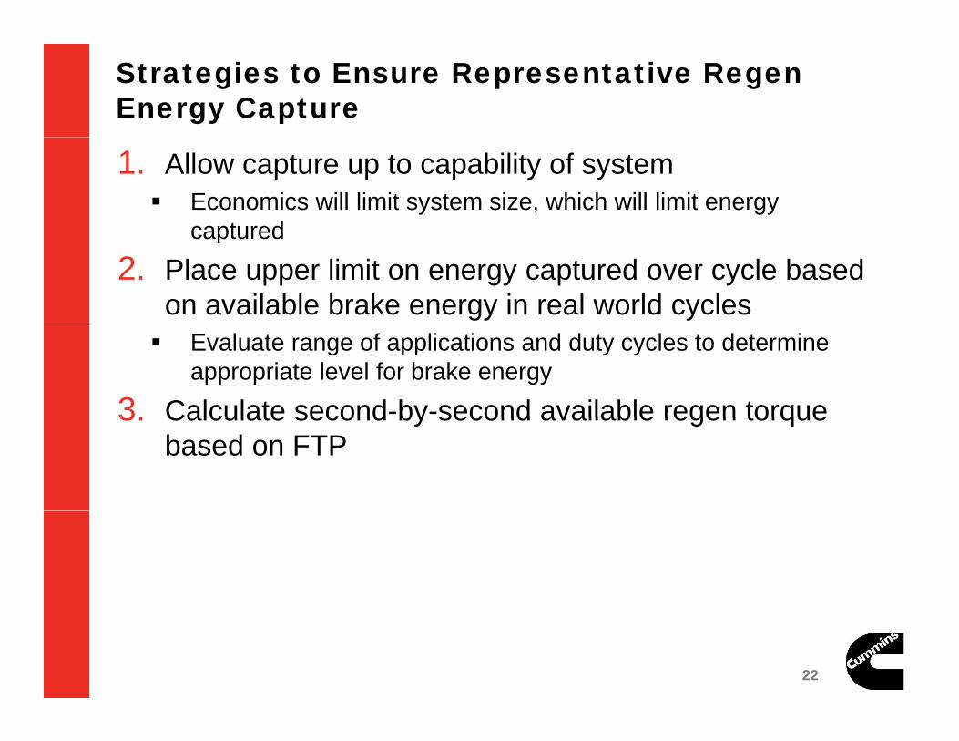
Strategies to Ensure Representative Regen Energy Capture
1. Allow capture up to capability of system Economics will limit system size, which will limit energy
capturedcaptured
2. Place upper limit on energy captured over cycle based on available brake energy in real world cycles Evaluate range of applications and duty cycles to determine
appropriate level for brake energy
3. Calculate second-by-second available regen torque3. Calculate second by second available regen torque based on FTP
22 22
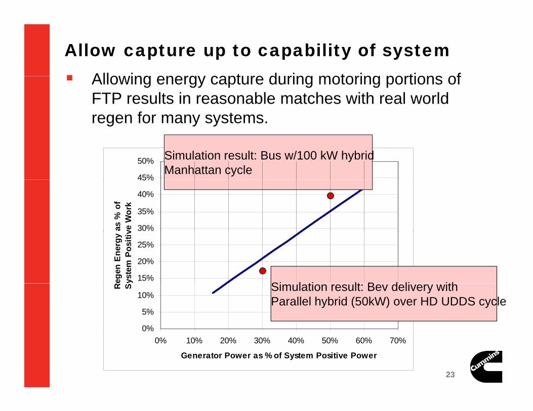
Allow capture up to capability of system Allo ing energ capt re d ring motoring portions of Allowing energy capture during motoring portions of
FTP results in reasonable matches with real world regen for many systems.
45%
50% Simulation result: Bus w/100 kW hybridManhattan cycle
30%
35%
40%
45%
as %
of
ve W
ork
15%
20%
25%
Rege
n En
ergy
ys
tem
Pos
itiv
Si l ti lt B d li ith
0%
5%
10%
R S Simulation result: Bev delivery withParallel hybrid (50kW) over HD UDDS cycle
23 23
0% 10% 20% 30% 40% 50% 60% 70%
Generator Power as % of System Positive Power

Allow capture up to capability of system
Example of system, engine, and regen torque curves
800
1200
1600
(Nm
)
System torque curve defines positiveFTP torque & speed requirements
-400
0
400
Torq
ue (
Motor & battery capability define-800
800 1300 1800 2300 2800
Speed (RPM)
System Torque Engine Torque Regen Capability
Motor & battery capability defineregen torque curve
During motoring portions of FTP,regen torque curve defines torque
24 24
System Torque Engine Torque Regen Capability

Place upper limit on energy captured over cycle based on available brake energy in real world cycles
45%
50% Bus: Max availableM h tt
30%
35%
40%
45%
as %
of
e W
ork
regen over Manhattan
15%
20%
25%
30%
gen
Ener
gy a
stem
Pos
itive P&D: Max available
regen over HTUF P&D
0%
5%
10%
15%
Re Sys
0%0% 10% 20% 30% 40% 50% 60% 70%
Generator Power as % of System Positive Power
25 25

Strategies to Ensure Representative Regen Energy Capture:gy pCalculation of Available Regen Energy
FTP defines speed & torque – Power– Good match between FTP & real world vehicle power p
requirements
By making an assumption on a typical vehicle for a given torque curve it is possible to calculate a second bytorque curve – it is possible to calculate a second-by-second regen energy limit.
26 26

Methodology
1000
1500
2000
2500
Spe
ed (R
PM
)
1000
1500
2000
2500
Spe
ed (R
PM
)
Modified FTP Engine SpeedOriginal FTP Engine Speed Example:
- Engine FTP Cycle to Vehicle FTP Cycle
0 200 400 600 800 1000 12000
500
Time (sec)
800
1000
0 200 400 600 800 1000 12000
500
Time (sec)
800
1000
- ISC 8.3L, 330hp Engine
- 55000 lbs vehicle
- Assumptions on frontal area, drag coefficient, rolling resistance, first gear
0 200 400 600 800 1000 1200-200
0
200
400
600
Time (sec)
Torq
ue (f
t-lb)
0 200 400 600 800 1000 1200-200
0
200
400
600
Time (sec)
Torq
ue (f
t-lb)
FTP defines speed and torque requirements for engine
coefficient, rolling resistance, first gear & final drive ratio
- Assumption on coasting vs. braking regimes
p q q gAcceleration: If engine torque positive, engine speed and torque can be used to
determine power going to wheels to accelerate vehicle
onAcceleratiMassForceForce *
MV
PMgfVAreaC
MVP
Accel
onAcceleratiMassForceForce
accessoryrollingaird
Eng
VehLoadEngine
2***21
*
27 27
Deceleration: Engine torque negative– If engine speed ~ constant assume coasting and calculate deceleration based on motoring engine
torque.– If engine speed decelerates quickly, assume braking at 1.5 m/s2

MethodologyIdle Speed modified to Engine OFF,
vehicle speed=0mph
Acceleration: Use formula to calculate
vehicle speed
Deceleration: Braking to 0
speed at 1.5m/s2
1000
1500
2000
2500
Spe
ed (R
PM
)
1000
1500
2000
2500
Spe
ed (R
PM
)
Modified FTP Engine SpeedOriginal FTP Engine Speed
p p
50
60
70g y
0 200 400 600 800 1000 12000
500
Time (sec)
800
1000
0 200 400 600 800 1000 12000
500
Time (sec)
800
1000
20
30
40
50
Veh
icle
Spe
ed (m
ph)
Coasting: Use formula to calculate
coasting speed
0 200 400 600 800 1000 1200-200
0
200
400
600
Time (sec)
Torq
ue (f
t-lb)
0 200 400 600 800 1000 1200-200
0
200
400
600
Time (sec)
Torq
ue (f
t-lb)
FTP defines speed and torque requirements for engine0 200 400 600 800 1000 1200
0
10
Time (sec)
FTP defines speed and torque requirements for engineAcceleration: If engine torque positive, engine speed and torque can be
used to determine power going to wheels to accelerate vehicle
onAcceleratiMassForceForce *
MV
PMgfVAreaC
MVP
Accel
onAcceleratiMassForceForce
accessoryrollingaird
Eng
VehLoadEngine
2***21
*
28 28
Deceleration: Engine torque negative– If engine speed ~ constant assume coasting and calculate deceleration based on
motoring engine torque.– If engine speed decelerates quickly, assume braking at 1.5 m/s2

Proposed Vehicle FTP Cycle70
Vehicle FTP Cycle
ISC8 3L 330hp 55000lbs70
Averaged Vehicle FTP Cycle
40
50
60
ed (m
ph)
ISC8.3L,330hp,55000lbsISB6.7L,280hp,46500lbsISB4.5L,182hp,30250lbsISF3.8L,167hp,27750lbs
40
50
60
ed (m
ph)
10
20
30
Veh
icle
Spe
e
10
20
30
Veh
icle
Spe
eAveraged
0 200 400 600 800 1000 12000
10
Time (sec)
0 200 400 600 800 1000 1200
0
10
Time (sec)
B k E % f +
Engine for FTP Vehicle FTP3.8L 39.40
Brake Energy as % of +ve Traction Energy
4.5L 39.726.7L 44.938.3L 45.92Average 42.49
Matches with HD UDDS cycle potential of about 40 to 45% (based on application)
29 29
Conventional Engine FTP Cycle speed and torque can be used to define vehicle speed for Vehicle FTP Cycle

MethodologyIdle Speed modified to Engine OFF,
vehicle speed=0mph
Acceleration: Use formula to calculate
vehicle speed
Deceleration: Braking to 0
speed at 3mph/s
1000
1500
2000
2500
Spe
ed (R
PM
)
1000
1500
2000
2500
Spe
ed (R
PM
)
Modified FTP Engine SpeedOriginal FTP Engine Speed
p p
0
500Vehicle FTP Cycle Traction & Braking Power
0 200 400 600 800 1000 12000
500
Time (sec)
800
1000
0 200 400 600 800 1000 12000
500
Time (sec)
800
1000
Coasting: Use formula to calculate
coasting speed -1000
-500
Pow
er (k
W)
0 200 400 600 800 1000 1200-200
0
200
400
600
Time (sec)
Torq
ue (f
t-lb)
0 200 400 600 800 1000 1200-200
0
200
400
600
Time (sec)
Torq
ue (f
t-lb)
FTP defines speed and torque requirements for engine0 200 400 600 800 1000 1200
-2000
-1500
Time(sec)
FTP defines speed and torque requirements for engineAcceleration: If engine torque positive, engine speed and torque can be used to
determine power going to wheels to accelerate vehicle
onAcceleratiMassForceForce *
MV
PMgfVAreaC
MVP
Accel
onAcceleratiMassForceForce
accessoryrollingaird
Eng
VehLoadEngine
2***21
*
0
0
)**(
)**(
Accelwhen
Accelwhen
VAccelMPowerDriving
VAccelMPowerBraking
30 30
Deceleration: Engine torque negative– If engine speed ~ constant assume coasting and calculate deceleration based on motoring engine
torque.– If engine speed decelerates quickly, assume braking at 1.5 m/s2
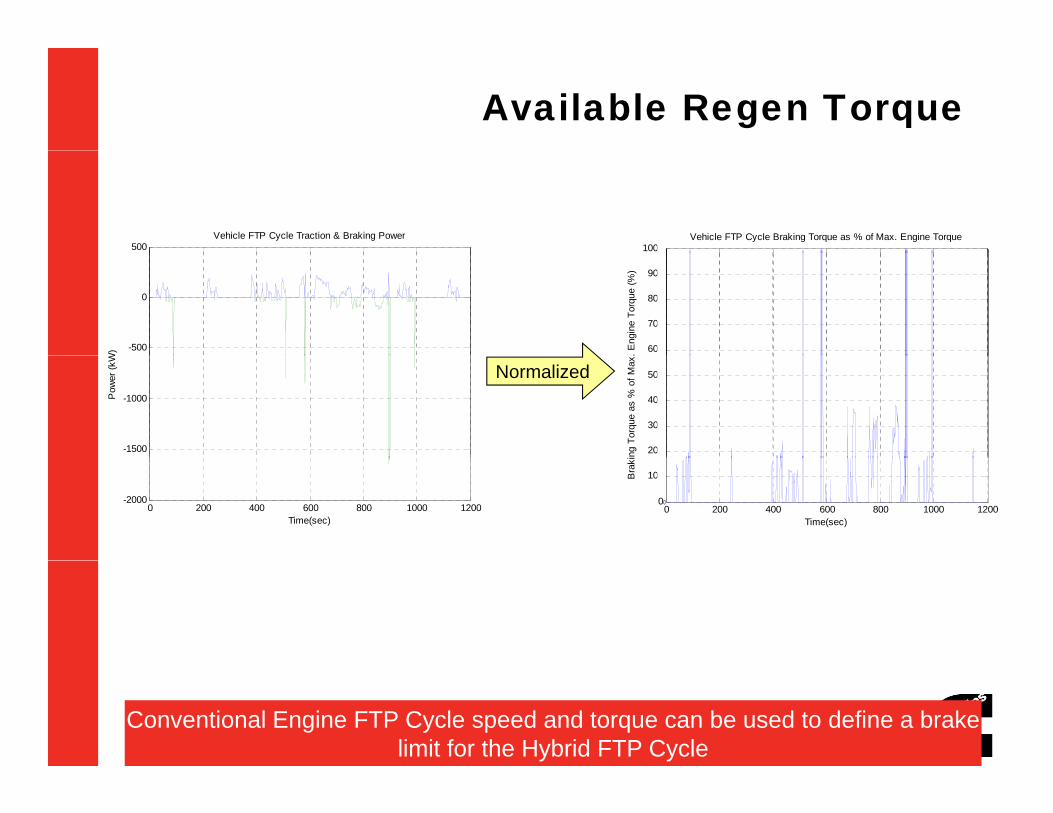
Available Regen Torque
500Vehicle FTP Cycle Traction & Braking Power
1000Vehicle FTP Cycle Braking Torque as % of Max. Engine Torque
00
-500
0
W) 600
700
800
900
. Eng
ine
Torq
ue (%
)
60
70
80
90
-1500
-1000Pow
er (k
W
200
300
400
500
ing
Torq
ue a
s %
of M
ax.
Normalized
20
30
40
50
0 200 400 600 800 1000 1200-2000
Time(sec)0 200 400 600 800 1000 1200
0
100
Time(sec)
Bra
ki
0
10
31 31Conventional Engine FTP Cycle speed and torque can be used to define a brake
limit for the Hybrid FTP Cycle