D GB USA F NL 22676 - Märklin · Safety Notes 13 Important Notes 13 Multi-Protocol Operation 13...
36
Modell des Schnelltriebwagen Baureihe SVT 137 22676 F D GB USA NL
Transcript of D GB USA F NL 22676 - Märklin · Safety Notes 13 Important Notes 13 Multi-Protocol Operation 13...
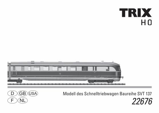
Modell des Schnelltriebwagen Baureihe SVT 137
22676F D GB USA
NL

2

3
Inhaltsverzeichnis: SeiteInformationen zum Vorbild 4Betriebshinweise 6Sicherheitshinweise 8Wichtige Hinweise 8Multiprotokollbetrieb 8Schaltbare Funktionen 11CV und Parameter 12Wartung und Instandhaltung 28Ersatzteile 33
Table of Contents: Page Information about the prototype 4Information about operation 6Safety Notes 13Important Notes 13Multi-Protocol Operation 13Controllable Functions 16CV and Parameter 17Service and maintenance 28Spare Parts 33
Sommaire : PageInformations concernant la locomotive réelle 5Remarques sur l’exploitation 6Remarques importantes sur la sécurité 18Information importante 18Mode multiprotocole 18Fonctions commutables 21CV et Paramètre 22Entretien et maintien 28Pièces de rechange 33
Inhoudsopgave: PaginaInformatie van het voorbeeld 5Opmerkingen over de werking 6Veiligheidsvoorschriften 23Belangrijke aanwijzing 23Multiprotocolbedrijf 23Schakelbare functies 26CV en Parameter 27Onderhoud en handhaving 28Onderdelen 33

4
Informationen zum Vorbild:Die 13 Schnelltriebwagen der Bauart „Hamburg“ waren ursprünglich alle mit elektrischer Kraftübertragung ausge-rüstet. Angetrieben wurden die beiden Achsen des in der Zugmitte vorhandenen Jacobs-Drehgestells. Ende der 40er Jahre wurden die nach dem Zweiten Weltkrieg noch vor-handenen Fahrzeuge instandgesetzt, als VT 04.1 bezeichnet und erhielten den inzwischen für Triebzüge üblichen roten Anstrich. Eingesetzt wurden sie stets zusammen mit den dreiteiligen VT 06.1 im hochwertigen Schnellverkehr. Ab 1959 wurden alle VT 04.1 an die Deutsche Reichsbahn der DDR abgegeben. Im Jahr 1951 erfolgte der Umbau des SVT 137 227 von der elektrischen auf eine hydraulische Kraftübertragung. Nach dem Einbau des hydrodynamischen Getriebes der Bauart Voith konnten die Achsen der beiden Enddrehgestelle ange-trieben werden, das Jacobs-Gestell wurde zum Laufgestell. Dieser Einzelgänger wurde daraufhin umbenannt zum VT 04.501 und ebenfalls rot lackiert mit gelben Begleitstreifen. Eine Seitenwand pro Fahrzeugseite erhielt den Schriftzug „DEUTSCHE BUNDESBAHN“.Eingesetzt wurde der VT 04.5 als hochwertiger Fern-Triebzug ( FT 231 ) unter dem Namen „Montan-Express“ zwischen Frankfurt und Luxembourg von 1953 bis 1955.
Information about the Prototype:The 13 „Hamburg“ design express powered rail cars were originally all equipped with electric power transmission. The two axles in the Jacobs truck in the middle of the train were powered. At the end of the Forties, the units still in existence after the end of World War II were overhauled, designated as the class VT 04.1, and were painted in the red paint scheme that had become customary for powered rail car trains. They were always used together with the three-part class VT 06.1 in important express passenger service. Starting in 1959, all of the class VT 04.1 units were given to the German State Railroad in East Germany.In 1951, road no. SVT 137 227 was converted from electric to hydraulic power transmission. After the installation of the Voith design hydrodynamic gear drive, the axles on both end trucks could be powered, and the Jacobs truck became a non-powered support truck. This one-off unit was re-designated as the class VT 04.501 and was also painted red with yellow striping. The lettering „DEUTSCHE BUNDESBAHN“ was applied to one side wall per side of this powered rail car.The VT 04.5 was used as an important long-distance train (FT 231) under the name „Montan-Express“ between Frank-furt and Luxembourg from 1953 to 1955.

5
Informations relatives au modèle réel :Les 13 automotrices rapides de type «Hamburg» étaient ini-tialement toutes équipées d’une transmission électrique. Les deux essieux du bogie Jacob situé au milieu du train étaient moteurs. A la fin des années quarante, les véhicules encore disponibles après la seconde guerre mondiale furent remis en état, immatriculés dans la série VT 04.1 et dotés de la livrée rouge, devenue la règle pour les trains automoteurs. Ils étaient toujours utilisés dans le trafic rapide haut de gamme, en combinaison avec les VT 06.1 à trois éléments. A partir de 1959, tous les VT 04.1 furent cédés à la Deutsche Reichsbahn de la RDA.En 1951, la transmission électrique du SVT 137 227 fut échan-gée contre une transmission hydraulique. L’installation de la transmission hydraulique de type Voith permettait d’entraîner les essieux des deux bogies d’extrémités, le bogie Jacob deve-nant porteur. Cet engin unique fut alors rebaptisé en VT 04.501 et également doté d’une livrée rouge avec des bandes jaunes. Un flanc de chaque côté reçut l’inscription «DEUTSCHE BUNDESBAHN».De 1953 à 1955, le VT 04.5 fut utilisé comme train automoteur de grandes lignes haut de gamme (FT 231) sous le nom «Mon-tan-Express» entre Francfort et Luxembourg.
Informatie over het voorbeeld:Oorspronkelijk waren de 13 sneltreinstellen van de serie “Hamburg” allemaal uitgerust met een elektrische overbren-ging. De aangedreven assen bevonden zich in het Jacobs-draaistel in het midden van het treinstel. Aan het eind van de veertiger jaren werden de treinstellen, die na de oorlog nog bruikbaar waren, hersteld en als VT 04.1 aangeduid. Ook werden ze in de rode, intussen voor treinstellen gebruike-lijke kleur, geschilderd. Ze werden altijd gezamenlijk met de driedelige VT 06.1 ingezet in de hoogwaardige sneltrein-dienst. Na 1959 werden alle VT 04.1 aan de Deutsche Reichsbahn van de DDR verkocht.In 1951 werd de SVT 137 227 omgebouwd van elektrische naar hydraulische overbrenging. Na het inbouwen van de hydrodynamische aandrijving van het type Voith, konden de assen van de beide buitenste draaistellen aangedreven wor-den en het Jacobs-draaistel werd een gewoon loopdraai-stel. Dit uitzonderlijke treinstel werd daarom omgenummerd naar VT 04.501 en eveneens rood geschilderd. Eén zijwand per treinstelzijde kreeg het opschrift “DEUTSCHE BUNDESBAHN”. De VT 04.5 werd van 1953 tot 1955 ingezet als hoogwaardige lange-afstandstreinstel (FT 231) met de naam “Montan-Express” tussen Frankfurt en Luxemburg.

6
Doppeleinheit nicht abknicken.Beschädigungsgefahr!
Do not bend this double unit train such it is kinked.You may damage the two units!
Ne pas rompre l’unité double en pliant.Il y a risque de dégât !
De dubbele eenheid niet knikken.Gevaar voor beschadigen!

7
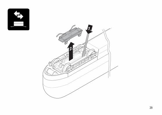
Vor Inbetriebnahme Transportschutz zwischen denbeiden Teilen entfernen!
Remove the protective cushioning placed betweenthe two parts for transportation purposes beforeusing these parts for the first time!
Avant la première mise en service, ôtez la protectionpour le transport située entre les deux parties!
Voor het in bedrijf nemen de transportbeveiligingtussen de beide delen verwijderen.

8
Sicherheitshinweise • Die Lok darf nur mit einem dafür bestimmten Betriebssys-
tem eingesetzt werden.• Analog max. 15 Volt =, digital max. 22 Volt ~. • Die Lok darf nur aus einer Leistungsquelle versorgt
werden.• Beachten Sie unbedingt die Sicherheitshinweise in der
Bedienungsanleitung zu Ihrem Betriebssystem.• Für den konventionellen Betrieb der Lok muss das An-
schlussgleis entstört werden. Dazu ist das Entstörset 611 655 zu verwenden. Für Digitalbetrieb ist das Entstör-set nicht geeignet.
• ACHTUNG! Funktionsbedingte scharfe Kanten und Spitzen.• Setzen Sie das Modell keiner direkten Sonneneinstrah-
lung, starken Temperaturschwankungen oder hoher Luftfeuchtigkeit aus.
• Verbaute LED`s entsprechen der Laserklasse 1 nach Norm EN 60825-1.
Wichtige Hinweise • Die Bedienungsanleitung und die Verpackung sind
Bestandteile des Produktes und müssen deshalb aufbe-wahrt sowie bei Weitergabe des Produktes mitgegeben werden.
• Für Reparaturen oder Ersatzteile wenden Sie sich bitte an Ihren Trix-Fachhändler.
• Gewährleistung und Garantie gemäß der beiliegenden Garantieurkunde.
• Entsorgung: www.maerklin.com/en/imprint.html
• Der volle Funktionsumfang ist nur unter Trix Systems, DCC und unter mfx verfügbar.
• Eingebaute, fahrtrichtungsabhängige Stirnbeleuchtung. Im Digitalbetrieb schaltbar.
• Befahrbarer Mindestradius 360 mm.
Multiprotokollbetrieb AnalogbetriebDer Decoder kann auch auf analogen Anlagen oder Gleis-abschnitten betrieben werden. Der Decoder erkennt die analoge Gleichspannung (DC) automatisch und passt sich der analogen Gleisspannung an. Es sind alle Funktionen, die unter mfx oder DCC für den Analogbetrieb eingestellt wurden aktiv (siehe Digitalbetrieb).
DigitalbetriebDer Decoder ist ein Multiprotokolldecoder. Der Decoder kann unter folgenden Digital-Protokollen eingesetzt werden: mfx oder DCC. Das Digital-Protokoll mit den meisten Möglichkeiten ist das höchstwertige Digital-Protokoll. Die Reihenfolge der Digital-Protokolle ist in der Wertung fallend: Priorität 1: mfx Priorität 2: DCC Priorität 3: DCHinweis: Werden zwei oder mehrere Digital-Protokolle am Gleis erkannt, übernimmt der Decoder automatisch das höchstwertige Digital-Protokoll; z.B. wird mfx & DCC erkannt wird das mfx-Digital-Protokoll vom Decoder übernommen.

9
Hinweis: Beachten Sie, dass nicht alle Funktionen in allen Digital-Protokollen möglich sind. Unter mfx und DCC können einige Einstellungen von Funktionen, welche im Analog-Betrieb wirksam sein sollen, vorgenommen werden.
Hinweise zum Digitalbetrieb • Die genaue Vorgehensweise zum Einstellen der diversen
Parameter entnehmen Sie bitte der Bedienungsanleitung Ihrer Mehrzug-Zentrale.
• Die ab Werk eingestellten Werte sind für mfx gewählt, so dass ein bestmöglichstes Fahrverhalten gewährleistet ist. Für andere Betriebssysteme müssen gegebenenfalls Anpassungen getätigt werden.
• Der Betrieb mit gegenpoliger Gleichspannung im Bremsabschnitt ist mit der werkseitigen Einstellung nicht möglich. Ist diese Eigenschaft gewünscht, so muss auf den konventionellen Gleichstrombetrieb verzichtet werden (CV 29/Bit 2 = 0).
mfx-Protokoll
Adressierung • Keine Adresse erforderlich, jeder Decoder erhält eine
einmalige und eindeutige Kennung (UID).• Der Decoder meldet sich an einer Central Station oder
Mobile Station mit seiner UID automatisch an.• Name ab Werk: 137 225 DB AG
Programmierung• Die Eigenschaften können über die grafische Oberfläche
der Central Station bzw. teilweise auch mit der Mobile Station programmiert werden.
• Es können alle Configuration Variablen (CV) mehrfach gelesen und programmiert werden.
• Die Programmierung kann entweder auf dem Haupt- oder dem Programmiergleis erfolgen.
• Die Defaulteinstellungen (Werkseinstellungen) können wieder hergestellt werden.
• Funktionsmapping: Funktionen können mit Hilfe der Central Station 60212 (eingeschränkt) und mit der Central Station 60213/60214/60215 beliebigen Funktionstasten zugeordnet werden (siehe Hilfe in der Central Station).

10
DCC-Protokoll
Adressierung• Mögliche Adressen: Kurze, lange und Traktionsadresse• Adressbereich:
1 – 127 (kurze Adresse, Traktionsadresse) 1 – 10239 (lange Adresse)• Jede Adresse ist manuell programmierbar.• Kurze oder lange Adresse wird über die CVs ausgewählt.• Eine angewandte Traktionsadresse deaktiviert die
Standard-Adresse.
Programmierung• Die Eigenschaften können über die Configurations Vari-
ablen (CV) mehrfach geändert werden. • Die CV-Nummer und die CV-Werte werden direkt einge-
geben.• Die CVs können mehrfach gelesen und programmiert
werden (Programmierung auf dem Programmiergleis).• Die CVs können beliebig programmiert werden. PoM
(Programmierung auf dem Hauptgleis PoM) ist nur bei den in der CV-Tabelle gekennzeichneten CV möglich. PoM muss von Ihrer Zentrale unterstützt werden (siehe Bedienungsanleitung ihres Gerätes).
• Die Defaulteinstellungen (Werkseinstellungen) können wieder hergestellt werden.
• 14 bzw. 28/126 Fahrstufen einstellbar. • Alle Funktionen können entsprechend dem Funktions-
mapping geschaltet werden.• Weitere Information, siehe CV-Tabelle DCC-Protokoll.
Es wird empfohlen, die Programmierungen grundsätzlich auf dem Programmiergleis vorzunehmen.
Logische Funktionen
Anfahr-/Bremsverzögerung• Die Beschleunigungs- und Bremszeit können getrennt
von einander eingestellt werden. • Die logische Funktionsabschaltung ABV kann über das
Funktionsmapping auf jede beliebige Funktionstaste gelegt werden.
11
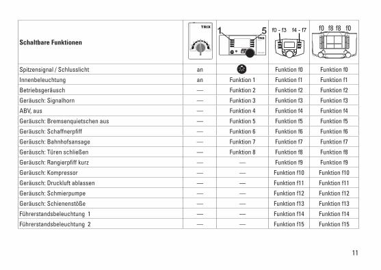
Schaltbare Funktionen
Spitzensignal / Schlusslicht an Funktion f0 Funktion f0
Innenbeleuchtung an Funktion 1 Funktion f1 Funktion f1
Betriebsgeräusch — Funktion 2 Funktion f2 Funktion f2
Geräusch: Signalhorn — Funktion 3 Funktion f3 Funktion f3
ABV, aus — Funktion 4 Funktion f4 Funktion f4
Geräusch: Bremsenquietschen aus — Funktion 5 Funktion f5 Funktion f5
Geräusch: Schaffnerpfiff — Funktion 6 Funktion f6 Funktion f6
Geräusch: Bahnhofsansage — Funktion 7 Funktion f7 Funktion f7
Geräusch: Türen schließen — Funktion 8 Funktion f8 Funktion f8
Geräusch: Rangierpfiff kurz — — Funktion f9 Funktion f9
Geräusch: Kompressor — — Funktion f10 Funktion f10
Geräusch: Druckluft ablassen — — Funktion f11 Funktion f11
Geräusch: Schmierpumpe — — Funktion f12 Funktion f12
Geräusch: Schienenstöße — — Funktion f13 Funktion f13
Führerstandsbeleuchtung 1 — — Funktion f14 Funktion f14
Führerstandsbeleuchtung 2 — — Funktion f15 Funktion f15
STOP mobile station
1 5 f0 f8 f0f8f0 - f3 f4 - f7

12
CV Bedeutung Wert DCC ab Werk
1 Adresse 1 - 127 3 2 PoM Minimalgeschwindigkeit 0 - 255 23 PoM Anfahrverzögerung 0 - 255 124 PoM Bremsverzögerung 0 - 255 125 PoM Maximalgeschwindigkeit 0 - 255 2258 Werkreset/Herstellerkennung 8 131
13 PoM Funktionen F1 - F8 im Analogbetrieb 0 - 255 014 PoM Funktionen F9 - F15 und Licht im Analogbetrieb 0 - 255 117 Erweiterte Adresse (oberer Teil) CV 29, Bit 5 =1 19218 Erweiterte Adresse (unterer Teil) CV 29, Bit 5 =1 12819 Traktionsadresse 0 - 255 021 PoM Funktionen F1 - F8 bei Traktion 0 - 255 022 PoM Funktionen F9 - F15 und Licht bei Traktion 0 - 255 0
29 PoM
Bit 0: Umpolung Fahrtrichtung Bit 1: Anzahl Fahrstufen 14 oder 28/128* Bit 2: DCC Betrieb mit Bremsstrecke (kein Analogbetrieb möglich) Bit 5: kurze / lange Adresse
0 / 1 0 / 2 0 / 4 0 / 32
0, 1, 2, 3, 4, 5, 6, 7, 32, 34, 35, 36,
37, 38, 396
63 PoM Lautstärke 0 - 255 240
* Fahrstufen am Lokdecoder und am Steuergerät müssen übereinstimmen, es sind sonst Fehlfunktionen möglich.
13
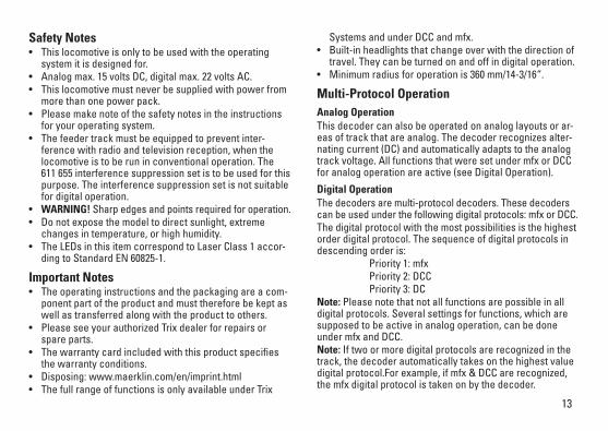
Systems and under DCC and mfx.• Built-in headlights that change over with the direction of
travel. They can be turned on and off in digital operation. • Minimum radius for operation is 360 mm/14-3/16“.
Multi-Protocol Operation Analog OperationThis decoder can also be operated on analog layouts or ar-eas of track that are analog. The decoder recognizes alter-nating current (DC) and automatically adapts to the analog track voltage. All functions that were set under mfx or DCC for analog operation are active (see Digital Operation).
Digital OperationThe decoders are multi-protocol decoders. These decoders can be used under the following digital protocols: mfx or DCC.The digital protocol with the most possibilities is the highest order digital protocol. The sequence of digital protocols in descending order is: Priority 1: mfx Priority 2: DCC Priority 3: DCNote: Please note that not all functions are possible in all digital protocols. Several settings for functions, which are supposed to be active in analog operation, can be done under mfx and DCC. Note: If two or more digital protocols are recognized in the track, the decoder automatically takes on the highest value digital protocol.For example, if mfx & DCC are recognized, the mfx digital protocol is taken on by the decoder.
Safety Notes• This locomotive is only to be used with the operating
system it is designed for.• Analog max. 15 volts DC, digital max. 22 volts AC. • This locomotive must never be supplied with power from
more than one power pack.• Please make note of the safety notes in the instructions
for your operating system.• The feeder track must be equipped to prevent inter-
ference with radio and television reception, when the locomotive is to be run in conventional operation. The 611 655 interference suppression set is to be used for this purpose. The interference suppression set is not suitable for digital operation.
• WARNING! Sharp edges and points required for operation.• Do not expose the model to direct sunlight, extreme
changes in temperature, or high humidity. • The LEDs in this item correspond to Laser Class 1 accor-
ding to Standard EN 60825-1.
Important Notes• The operating instructions and the packaging are a com-
ponent part of the product and must therefore be kept as well as transferred along with the product to others.
• Please see your authorized Trix dealer for repairs or spare parts.
• The warranty card included with this product specifies the warranty conditions.
• Disposing: www.maerklin.com/en/imprint.html • The full range of functions is only available under Trix

14
Notes on digital operation • The operating instructions for your central unit will give
you exact procedures for setting the different parame-ters.
• The values set at the factory have been selected for mfx in order to guarantee the best possible running characte-ristics. Adjustments may have to be made for other operating systems.
• The setting done at the factory does not permit operation with opposite polarity DC power in the braking block. If you want this characteristic, you must do without conventional DC power operation (CV 29/Bit 2 = 0).
mfx Protocol
Addresses • No address is required; each decoder is given a one-
time, unique identifier (UID).• The decoder automatically registers itself on a Central
Station or a Mobile Station with its UID.• Name set at the factory: 137 225 DB AG
Programming • The characteristics can be programmed using the
graphic screen on the Central Station or also partially with the Mobile Station.
• All of the Configuration Variables (CV) can be read and programmed repeatedly.
• The programming can be done either on the main track or the programming track.
• The default settings (factory settings) can be produced repeatedly.
• Function mapping: Functions can be assigned to any of the function buttons with the help of the 60212 Central Station (with limitations) and with the 60213/60214/60215 Central Station (See help section in the Central Station).

15
DCC Protocol
Addresses • Possible addresses: short, long, and m.u. address• Address range:
1 – 127 (short address, m.u. address) 1 – 10239 (long address)
• Every address can be programmed manually.• A short or a long address is selected using the CVs.• A multiple unit address that is being used deactivates the
standard address.
Programming• The characteristics can be changed repeatedly using the
Configuration Variables (CV).• The CV numbers and the CV values are entered directly.• The CVs can be read and programmed repeatedly. (Pro-
gramming is done on the programming track.)• The CVs can be programmed, as you desire. PoM (Pro-
gramming on the layout track) is only possible with those CVs marked in the CV table. PoM must be supported by your central controller (see the instructions for your controller).
• The default settings (factory settings) can be produced repeatedly.
• 14 or 28/126 speed levels can be set.• All of the functions can be controlled according to the
function mapping (see CV description).• See the CV description for the DCC protocol for additional
information.
We recommend that in general programming should be done on the programming track.
Logic Functions
Acceleration / Braking Delay• The acceleration and braking times can be set separately
from each other. • The logical function shut off for ABV (Acceleration /
Braking Delay) can be assigned to any function button by means of function mapping.

16
Controllable Functions
Headlights / Marker lights on Function f0 Function f0
Interior lights on Function 1 Function f1 Function f1
Locomotive operating sounds — Function 2 Function f2 Function f2
Sound effect: Horn — Function 3 Function f3 Function f3
ABV, off — Function 4 Function f4 Function f4
Sound effect: Squealing brakes off — Function 5 Function f5 Function f5
Sound effect: Conductor whistle — Function 6 Function f6 Function f6
Sound effect: Station announcements — Function 7 Function f7 Function f7
Sound effect: Doors being closed — Function 8 Function f8 Function f8
Sound effect: Short switching whistle — — Function f9 Function f9
Sound effect: Compressor — — Function f10 Function f10
Sound effect: Letting off air — — Function f11 Function f11
Sound effect: Lubrication pump — — Function f12 Function f12
Sound effect: Rail joints — — Function f13 Function f13
Engineer‘s cab lighting 1 — — Function f14 Function f14
Engineer‘s cab lighting 2 — — Function f15 Function f15
STOP mobile station
1 5 f0 f8 f0f8f0 - f3 f4 - f7
17
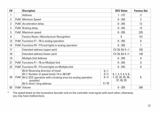
* The speed levels on the locomotive decoder and on the controller must agree with each other; otherwise, you may have malfunctions.
CV Discription DCC Value Factory-Set
1 Address 1 - 127 3 2 PoM Minimum Speed 0 - 255 23 PoM Acceleration delay 0 - 255 124 PoM Braking delay 0 - 255 125 PoM Maximum speed 0 - 255 2258 Factory Reset / Manufacturer Recognition 8 13113 PoM Functions F1 - F8 in analog operation 0 - 255 014 PoM Functions F9 - F15 and lights in analog operation 0 - 255 117 Extended address (upper part) CV 29, Bit 5 =1 19218 Extended address (lower part) CV 29, Bit 5 =1 12819 Multiple Unit Address 0 - 255 021 PoM Functions F1 - F8 on Multiple Unit 0 - 255 022 PoM Functions F9 - F15 and lights on Multiple Unit 0 - 255 0
29 PoM
Bit 0: Reversing direction of travel Bit 1: Number of speed levels 14 or 28/128*Bit 2: DCC operation with a braking area (no analog operation possible) Bit 5: short / long address
0 / 1 0 / 2 0 / 4
0 / 32
0, 1, 2, 3, 4, 5, 6, 7, 32, 34, 35, 36,
37, 38, 396
63 PoM Volume 0 - 255 240

18
Remarques importantes sur la sécurité • La locomotive ne peut être utilisée qu‘avec le système
d‘exploitation indiqué.• Analogique max. 15 Volt =, digital max. 22 Volt ~. • La locomotive ne peut pas être alimentée électriquement
par plus d‘une source de courant à la fois.• Il est impératif de tenir compte des remarques sur la
sécurité décrites dans le mode d‘emploi de votre système d‘exploitation.
• Pour l’exploitation de la locomotive en mode convention-nel, la voie de raccordement doit être déparasitée. A cet effet, utiliser le set de déparasitage réf. 611 655. Le set de déparasitage ne convient pas pour l’exploitation en mode numérique.
• ATTENTION! Pointes et bords coupants lors du fonctionne-ment du produit.
• Ne pas exposer le modèle à un ensoleillement direct, à de fortes variations de température ou à un taux d‘humidité important.
• Les DEL installées correspondent à la classe laser 1 selon la norme EN 60825-1.
Information importante• La notice d‘utilisation et l’emballage font partie intégrante
du produit ; ils doivent donc être conservés et, le cas échéant, transmis avec le produit.
• Pour toute réparation ou remplacement de pièces, adres-sez vous à votre détaillant-spécialiste Trix.
• Garantie légale et garantie contractuelle conformément au certificat de garantie ci-joint.
• Elimination : www.maerklin.com/en/imprint.html • L’intégralité des fonctions est disponible uniquement en
exploitation Trix Systems, DCC et mfx. • Feux de signalisation s‘inversant selon le sens de mar-
che; feux commutables en exploitation digital. • Rayon minimal d’inscription en courbe 360 mm.
Mode multiprotocole Mode analogiqueOn peut aussi faire fonctionner le décodeur sur des instal-lations ou des sections de voie analogiques. Le décodeur identifie automatiquement la tension de voie analogique (DC). Toutes les fonctions qui ont été paramétrée pour le mode analogique sous mfx ou sous DCC sont actives (voir mode numérique).
Mode numériqueLes décodeur sont des décodeur multiprotocole. Le décodeur peut être utilisé avec les protocoles numériques suivants : mfx, DCCLe protocole numérique offrant les possibilités les plus nombreuses est le protocole numérique à bit de poids fort. La hiérarchisation des protocoles numériques est descendante : Priorité 1 : mfx Priorité 2 : DCC Priorité 3 : DCIndication : Si deux ou plus de deux protocoles numériques sont reconnus sur la voie, le décodeur choisit automatique-ment le protocole numérique le plus significatif. Entre les

19
protocoles mfx & DCC par exemple, le décodeur choisira le protocole numérique mfx.Indication : remarquez que toutes les fonctions ne peuvent pas être actionnées dans tous les protocoles numériques. Sous mfx et sous DCC, il est possible de procéder à quelques paramétrages de fonctions devant être actives dans le cadre de l’exploitation analogique.
Remarques relatives au fonctionnement en mode digital • En ce qui concerne la procédure de réglage des divers
paramètres, veuillez vous référer au mode d‘emploi de votre centrale de commande multitrain.
• Les valeurs paramétrées d’usine sont choisies pour mfx de manière à garantir le meilleur comportement de roulement possible. Pour d’autres systèmes d’exploitation, ces valeurs dev-ront éventuellement être adaptées.
• L’exploitation avec courant continu de polarité inverse dans les sections de freinage n’est pas possible avec le réglage d’usine. Si cette propriété est désirée, il faut alors renoncer à l’exploitation conventionnelle en cou-rant continu (CV 29/Bit 2 = 0).
Protocole mfx
Adressage • Aucune adresse n’est nécessaire, le décodeur reçoit tou-
tefois une identification unique et non équivoque (UID).• Avec son UID, le décodeur indique automatiquement
à une station centrale ou à une station mobile qu’il est connecté.
• Nom en codee en usine: 137 225 DB AG
Programmation• Les caractéristiques peuvent être programmées par
l’intermédiaire de la couche graphique de la station cen-trale, voire en partie aussi au moyen de la station mobile.
• Toutes les configurations variables (CV) peuvent être lues et programmées de façon réitérée.
• La programmation peut être réalisée soit sur la voie principale, soit sur la voie de programmation.
• Les paramétrages par défaut (paramétrages usine) peuvent être rétablis.
• Mappage des fonctions : les fonctions peuvent être affectées à de quelconques touches de fonction au moyen de la station centrale (60212) (restreinte) et avec la station centrale 60213/60214/60215 (voir Aide au niveau de la station centrale).
20
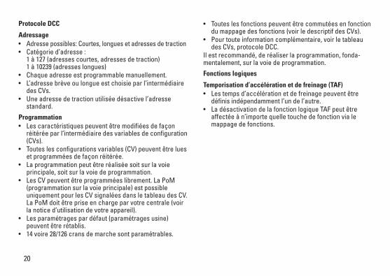
Protocole DCC
Adressage• Adresse possibles: Courtes, longues et adresses de traction• Catégorie d’adresse :
1 à 127 (adresses courtes, adresses de traction) 1 à 10239 (adresses longues)
• Chaque adresse est programmable manuellement.• L’adresse brève ou longue est choisie par l’intermédiaire
des CVs.• Une adresse de traction utilisée désactive l’adresse
standard.
Programmation• Les caractéristiques peuvent être modifiées de façon
réitérée par l’intermédiaire des variables de configuration (CVs).
• Toutes les configurations variables (CV) peuvent être lues et programmées de façon réitérée.
• La programmation peut être réalisée soit sur la voie principale, soit sur la voie de programmation.
• Les CV peuvent être programmées librement. La PoM (programmation sur la voie principale) est possible uniquement pour les CV signalées dans le tableau des CV. La PoM doit être prise en charge par votre centrale (voir la notice d’utilisation de votre appareil).
• Les paramétrages par défaut (paramétrages usine) peuvent être rétablis.
• 14 voire 28/126 crans de marche sont paramétrables.
• Toutes les fonctions peuvent être commutées en fonction du mappage des fonctions (voir le descriptif des CVs).
• Pour toute information complémentaire, voir le tableau des CVs, protocole DCC.
Il est recommandé, de réaliser la programmation, fonda-mentalement, sur la voie de programmation.
Fonctions logiques
Temporisation d’accélération et de freinage (TAF)• Les temps d’accélération et de freinage peuvent être
définis indépendamment l’un de l’autre. • La désactivation de la fonction logique TAF peut être
affectée à n’importe quelle touche de fonction via le mappage de fonctions.

21
Fonctions commutables
Fanal éclairage / Feu de fin de convoi activé Fonction f0 Fonction f0
Eclairage intérieur activé Fonction 1 Fonction f1 Fonction f1
Bruit de roulement — Fonction 2 Fonction f2 Fonction f2
Bruitage : Trompe, signal — Fonction 3 Fonction f3 Fonction f3
ABV, désactivé — Fonction 4 Fonction f4 Fonction f4
Bruitage : Grincement de freins désactivé — Fonction 5 Fonction f5 Fonction f5
Bruitage : Sifflet Contrôleur — Fonction 6 Fonction f6 Fonction f6
Bruitage : Annonce en gare — Fonction 7 Fonction f7 Fonction f7
Bruitage : Fermeture des portes — Fonction 8 Fonction f8 Fonction f8
Bruitage : Sifflet pour manœuvre court — — Fonction f9 Fonction f9
Bruitage : Compresseur — — Fonction f10 Fonction f10
Bruitage : Échappement de l‘air comprimé — — Fonction f11 Fonction f11
Bruitage : Distributeur d‘huile — — Fonction f12 Fonction f12
Bruitage : Joints de rail — — Fonction f13 Fonction f13
Eclairage de la cabine de conduite 1 — — Fonction f14 Fonction f14
Eclairage de la cabine de conduite 2 — — Fonction f15 Fonction f15
STOP mobile station
1 5 f0 f8 f0f8f0 - f3 f4 - f7

22
CV Affectation DCC Valeur Parm. Usine
1 Adresse 1 - 127 3 2 PoM Vitesse minimale 0 - 255 23 PoM Temporisation d‘accélération 0 - 255 124 PoM Temporisation de freinage 0 - 255 125 PoM Vitesse maximale 0 - 255 2258 Réinitialisation d’usine/identification du fabricant 8 131
13 PoM Fonctions F1 - F8 en mode analogique 0 - 255 014 PoM Fonctions F9 - F15 et éclairage en mode analogique 0 - 255 117 Adresse étendue (partie supérieure) CV 29, Bit 5 =1 19218 Adresse étendue (partie inférieure) CV 29, Bit 5 =1 12819 Adresse traction 0 - 255 021 PoM Fonctions F1 - F8 pour traction 0 - 255 022 PoM Fonctions F9 - F15 et éclairage traction 0 - 255 0
29 PoM
Bit 0 : Inversion du sens de marche Bit 1: Nombre de crans de marche 14 ou 28/128*Bit 2: Exploitation DCC avec section de freinage (exploitation analogique impossible) Bit 5: Adresse courte/longue
0 / 1 0 / 2 0 / 4
0 / 32
0, 1, 2, 3, 4, 5, 6, 7, 32, 34, 35, 36,
37, 38, 396
63 PoM Volume 0 - 255 240
* Pour éviter tout dysfonctionnement, les crans de marche sur le décodeur de loco doivent impérativement coïncider avec ceux de l’appareil de commande.
23
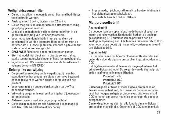
Veiligheidsvoorschriften• De loc mag alleen met een daarvoor bestemd bedrijfssys-
teem gebruikt worden.• Analoog max. 15 Volt =, digitaal max. 22 Volt ~. • De loc mag niet vanuit meer dan één stroomvoorziening
gelijktijdig gevoed worden.• Lees ook aandachtig de veiligheidsvoorschriften in de
gebruiksaanwijzing van uw bedrijfssysteem. • Voor het conventionele bedrijf met de loc dient de
aansluitrail te worden ontstoort. Hiervoor dient men de ontstoor-set 611 655 te gebruiken. Voor het digitale bedrijf is deze ontstoor-set niet geschikt.
• OPGEPAST! Functionele scherpe kanten en punten.• Stel het model niet bloot aan in directe zonnestraling,
sterke temperatuurwisselingen of hoge luchtvochtigheid.• Ingebouwde LED’s komen overeen met de laserklasse 1
volgens de norm EN 60825-1. Belangrijke aanwijzing• De gebruiksaanwijzing en de verpakking zijn een be-
standdeel van het product en dienen derhalve bewaard en meegeleverd te worden bij het doorgeven van het product.
• Voor reparaties en onderdelen kunt zich tot Uw Trix handelaar wenden.
• Vrijwaring en garantie overeenkomstig het bijgevoegde garantiebewijs.
• Afdanken:www.maerklin.com/en/imprint.html • De volledige toegang tot alle functies is alleen mogelijk
met Trix Systems, DCC of met mfx bedrijf.
• Ingebouwde, rijrichtingsafhankelijke frontverlichting is in het digitaalsysteem schakelbaar.
• Minimale te berijden radius: 360 mm.
MultiprotocolbedrijfAnaloogbedrijfDe decoder kan ook op analoge modelbanen of spoortra-jecten gebruikt worden. De decoder herkent de analoge gelijkspanning (DC) automatisch en past zich aan de analoge railspanning aan. Alle functies die onder mfx of DCC voor het analoge bedrijf zijn ingesteld, worden geactiveerd (zie digitaalbedrijf).
DigitaalbedrijfDe Decoder is een multiprotocoldecoder. De decoder kan onder de volgende digitale protocollen ingezet worden: mfx, DCC. Het digitaalprotocol met de meeste mogelijkheden is het primaire digitaalprotocol. De volgorde van de digitaalproto-collen is afnemend in mogelijkheden: Prioriteit 1: mfx Prioriteit 2: DCC Prioriteit 3: DCOpmerking: Als er twee of meer digitale protocollen op de rails worden herkend, dan neemt de decoder automa-tisch het hoogwaardigste protocol over; bijv. word mfx & DCC herkend, dan wordt het mfx signaal door de decoder overgenomen.Opmerking: let er op dat niet alle functies in alle digitaal-protocollen mogelijk zijn. Onder mfx of DCC kunnen enkele

24
instellingen, welke in analoogbedrijf werkzaam moeten zijn, ingesteld worden.
Aanwijzingen voor digitale besturing • Het op de juiste wijze instellen van de diverse parame-
ters staat beschreven in de handleiding van uw digitale Centrale.
• Fabrieksmatig zijn de waarden voor mfx zo ingestelt dat optimale rijeigenschappen gegarandeerd zijn. Voor andere bedrijfssystemen moeten eventueel aanpas-singen uitgevoerd worden.
• Het bedrijf met tegengepoolde gelijkspanning in de afrem-sectie is met de fabrieksinstelling niet mogelijk. Indien deze eigenschap wenselijk is, dan moet worden afgezien van het conventioneel gelijkstroombedrijf (CV 29/Bit 2 = 0).
mfx-protocol
Adressering • Een adres is niet nodig, elke decoder heeft een éénmalig
en éénduidig kenmerk (UID).• De decoder meldt zich vanzelf aan bij het Central Station
of Mobile Station met zijn UID.• Naam af de fabriek: 137 225 DB AG
Programmering • De eigenschappen kunnen m.b.v. het grafische scherm
op het Central Station resp. deels ook met het Mobile Station geprogrammeerd worden.
• Alle configuratie variabelen (CV) kunnen vaker gelezen en geprogrammeerd worden.
• De programmering kan zowel op het hoofdspoor als op het programmeerspoor gebeuren.
• De default-instellingen (fabrieksinstelling) kunnen weer hersteld worden.
• Functiemapping: functies kunnen met behulp van het Central Station 60212 (met beperking) en met het Central Station 60213/60214/60215 aan elke gewenste functietoets worden toegewezen (zie het helpbestand in het Central Station).
25
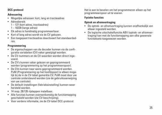
DCC-protocol
Adressering • Mogelijke adressen: kort, lang en tractieadres• Adresbereik:
1 – 127 (kort adres, tractieadres) 1 – 10239 (lange adres)
• Elk adres is handmatig programmeerbaar.• Kort of lang adres wordt via de CV gekozen.• Een toegepast tractieadres deactiveert het standaardad-
res.
Programmering• De eigenschappen van de decoder kunnen via de confi-
guratie variabelen (CV) vaker gewijzigd worden.• De CV-nummers en de CV-waarden worden direct inge-
voerd.• De CV’s kunnen vaker gelezen en geprogrammeerd
worden (programmering op het programmeerspoor).• De CVs kunnen naar wens geprogrammeerd worden.
PoM (Programmering op het hoofdspoor) is alleen moge-lijk bij de in de CV-tabel gemerkte CV. PoM moet door uw centrale ondersteund worden (zie de gebruiksaanwijzing van uw centrale).
• De default-instellingen (fabrieksinstelling) kunnen weer hersteld worden.
• 14 resp. 28/126 rijstappen instelbaar.• Alle functies kunnen overeenkomstig de functiemapping
geschakeld worden (zie CV-beschrijving).• Voor verdere informatie, zie de CV-tabel DCC-protocol.
Het is aan te bevelen om het programmeren alleen op het programmeerspoor uit te voeren.
Fysieke functies
Optrek en afremvertraging• De optrek- en afremvertraging kunnen onafhankelijk van
elkaar ingesteld worden. • De logische uitschakelfunctie ABV (optrek- en afremver-
traging) kan met de functiemapping aan elke gewenste functietoets toegewezen worden.
26
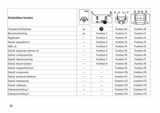
Schakelbare functies
Frontsein/ Sluitseinen an Funktion f0 Funktion f0
Binnenverlichting an Funktion 1 Funktion f1 Funktion f1
Rijgeluiden — Funktion 2 Funktion f2 Funktion f2
Geluid: signaalhoorn — Funktion 3 Funktion f3 Funktion f3
ABV, uit — Funktion 4 Funktion f4 Funktion f4
Geluid: piepende remmen uit — Funktion 5 Funktion f5 Funktion f5
Geluid: conducteurfluit — Funktion 6 Funktion f6 Funktion f6
Geluid: stationsomroep — Funktion 7 Funktion f7 Funktion f7
Geluid: deuren sluiten — Funktion 8 Funktion f8 Funktion f8
Geluid: rangeerfluit kort — — Funktion f9 Funktion f9
Geluid: compressor — — Funktion f10 Funktion f10
Geluid: perslucht afblazen — — Funktion f11 Funktion f11
Geluid: smeerpomp — — Funktion f12 Funktion f12
Geluid: raillassen — — Funktion f13 Funktion f13
Cabineverlichting 1 — — Funktion f14 Funktion f14
Cabineverlichting 2 — — Funktion f15 Funktion f15
STOP mobile station
1 5 f0 f8 f0f8f0 - f3 f4 - f7

27
* De rijstappen instelling op de decoder en het besturingsapparaat moeten met elkaar overeenkomen anders kunnen er storingen optreden.
CV Betekenis Waarde DCC Af fabriek
1 Adres 1 - 127 3 2 PoM Minimale snelheid 0 - 255 23 PoM Optrekvertraging 0 - 255 124 PoM Afremvertraging 0 - 255 125 PoM Maximumsnelheid 0 - 255 2258 Fabrieksinstelling/fabriekherkenning 8 13113 PoM functies F1 - F8 in analoogbedrijf 0 - 255 014 PoM functies F9 - F15 en licht in analoogbedrijf 0 - 255 117 Uitgebreld adres (bovenste gedeelte) CV 29, Bit 5 =1 19218 Uitgebreld adres (onderste gedeelte) CV 29, Bit 5 =1 12819 tractieadres 0 - 255 021 PoM functies F1 - F8 in tractie 0 - 255 022 PoM functies F9 - F15 en licht in tractie 0 - 255 0
29 PoM
Bit 0: ompoling rijrichting Bit 1: aantal rijstappen 14 of 28/128*Bit 2: DCC bedrijf met afremtraject (geen analoogbedrijf mogelijk) Bit 5: kort / lang adres
0 / 1 0 / 2 0 / 4
0 / 32
0, 1, 2, 3, 4, 5, 6, 7, 32, 34, 35, 36,
37, 38, 396
63 PoM Volume 0 - 255 240

28
29

30
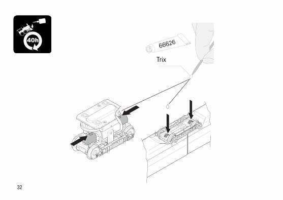
40h

31
2 2
32
TRIX 66626
40h
Trix

33
Det
ails
der
Dar
stel
lung
kö
nnen
von
dem
Mod
ell
abw
eich
en.
1
1
9
64
2
1
3 11
8
7
10
8
5
13
12
3
34
Det
ails
der
Dar
stel
lung
kö
nnen
von
dem
Mod
ell
abw
eich
en.
1
1
71515
14
8
8
6
4
9
10
16

35
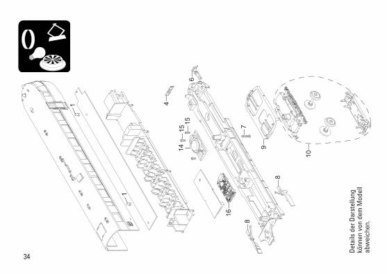
Hinweis: Einige Teile werden nur ohne oder mit anderer Farbgebung angeboten. Teile, die hier nicht aufgeführt sind, können nur im Rahmen einer Reparatur im Märklin-Reparatur-Service repariert werden.
Wagen A Wagen B
1 Schraube E786 790 E786 790 2 Faltenbalg E226 504 — 3 Zugfeder E765 630 — 4 Leiterplatte Stirnbel. E135 981 E253 406 5 Motor E250 425 — 6 Kupplungsimitation E226 449 E226 449 7 Schraube E308 468 E308 468 8 Blenden re. + li. E262 008 E262 008 9 Blenden vorne E262 009 E262 009 10 Drehgestell E269 584 E269 585 11 Treibgestell E253 402 — 12 Haftreifen E656 500 — 13 Schraube E756 090 — 14 Lautsprecher — E508 606 15 Schraube — E786 750 16 Decoder — 260 424

Gebr. Märklin & Cie. GmbH Stuttgarter Straße 55 - 57 73033 Göppingen Germanywww.trix.de
261374/1215/Kd1EfÄnderungen vorbehalten
© Gebr. Märklin & Cie. GmbH
Due to different legal requirements regarding electro-magnetic compatibility, this item may be used in the USA only after separate certification for FCC com-pliance and an adjustment if necessary. Use in the USA without this certification is not permitted and absolves us of any liability. If you should want such certification to be done, please contact us – also due to the additional costs incurred for this.
www.maerklin.com/en/imprint.html