DIN 18650-1
59
DEUTSCHE NORM December 2005 DIN 18650-1 { ICS 91.190 Supersedes DIN V 18650-1:2003-09 See start of validity Building hardware – Powered pedestrian doors – Part 1: Product requirements and test methods Schlösser und Baubeschläge – Automatische Türsysteme – Teil 1: Produktanforderungen und Prüfverfahren Document comprises 59 pages Translation by DIN-Sprachendienst. In case of doubt, the German-language original should be consulted as the authoritative text. © No part of this translation may be reproduced without prior permission of DIN Deutsches Institut für Normung e. V., Berlin. Beuth Verlag GmbH, 10772 Berlin, Germany, has the exclusive right of sale for German Standards (DIN-Normen). English price group 18 www.din.de www.beuth.de !,kh_" 07.06 9726960 Normen-Download-Beuth-NBN Bureau de Normalisation N.Entreprise: 0880.857.592-KdNr.142067-LfNr.3930151001-2008-02-18 16:09
Transcript of DIN 18650-1

DEUTSCHE NORM December 2005
DIN 18650-1 {
ICS 91.190
Supersedes DIN V 18650-1:2003-09 See start of validity
Building hardware – Powered pedestrian doors – Part 1: Product requirements and test methods
Schlösser und Baubeschläge – Automatische Türsysteme – Teil 1: Produktanforderungen und Prüfverfahren
Document comprises 59 pages
Translation by DIN-Sprachendienst. In case of doubt, the German-language original should be consulted as the authoritative text.
© No part of this translation may be reproduced without prior permission of DIN Deutsches Institut für Normung e. V., Berlin. Beuth Verlag GmbH, 10772 Berlin, Germany, has the exclusive right of sale for German Standards (DIN-Normen).
English price group 18 www.din.de
www.beuth.de !,kh_"07.06 9726960
B55EB1B3C7662F79D1B59483A53B9F2F82C98BEEB7939DA445904AABD0F3108428F74B48ACF2599291A069AD4957C493EE60A3B134FC6C47B63934BB29CA3698646CE1EA0B764DE7542A090C10C67614B2A77833B6ACB991FA0939A71F8A5028ED09BC82AF8ED7AFBE5DB130A880AE3AA07E51B58B45EC499F5B
No
rmen
-Do
wn
load
-Beu
th-N
BN
Bu
reau
de
No
rmal
isat
ion
N.E
ntr
epri
se:
0880
.857
.592
-Kd
Nr.
1420
67-L
fNr.
3930
1510
01-2
008-
02-1
8 16
:09

DIN 18650-1:2005-12
2
Start of validity
This standard is valid from 2005-12-01.
The previous edition, DIN V 18650-1:2003-09, will remain valid until 2006-06-30.
Contents
Page
Foreword......................................................................................................................................................... 4 1 Scope ................................................................................................................................................. 4 2 Normative references ....................................................................................................................... 4 3 Terms and definitions ...................................................................................................................... 6 4 Classification................................................................................................................................... 10 4.1 Coding system ................................................................................................................................ 10 4.2 Type of drive (first digit)................................................................................................................. 10 4.3 Drive durability (second digit) ....................................................................................................... 11 4.4 Type of door leaf (third digit)......................................................................................................... 11 4.5 Suitability for use as a fire door (fourth digit) ............................................................................. 11 4.6 Drive safety devices (fifth digit) .................................................................................................... 11 4.7 Special requirements for drives/functions/fittings (sixth digit) ................................................. 11 4.8 Safety of door leaf or leaves – Construction/installation (seventh digit) ................................. 12 4.9 Ambient temperature (eighth digit)............................................................................................... 12 4.10 Example of classification............................................................................................................... 12 5 Requirements .................................................................................................................................. 12 5.1 General............................................................................................................................................. 12 5.2 Product information........................................................................................................................ 13 5.3 Drive system.................................................................................................................................... 14 5.4 Door leaf or leaves.......................................................................................................................... 15 5.5 Manual operation ............................................................................................................................ 16 5.6 Tracks .............................................................................................................................................. 16 5.7 Avoidance of danger points and protection at danger points ................................................... 16 5.8 Additional requirements ................................................................................................................ 20 5.9 Additional requirements for powered doors used as fire doors ............................................... 25 5.10 Electromagnetic compatibility....................................................................................................... 25 6 Test methods................................................................................................................................... 25 6.1 General............................................................................................................................................. 25 6.2 Test conditions ............................................................................................................................... 26 6.3 Documentation required for testing.............................................................................................. 26 7 Test procedures .............................................................................................................................. 27 7.1 Durability test .................................................................................................................................. 27 7.2 Test for electromagnetic compatibility......................................................................................... 27 7.3 Special tests for danger points on revolving doors (except for low-energy powered
doors)............................................................................................................................................... 28 7.4 Tests for further requirements ...................................................................................................... 29 7.5 Test results...................................................................................................................................... 31 8 Marking ............................................................................................................................................ 32 9 Evaluation of conformity................................................................................................................ 32 9.1 General............................................................................................................................................. 32 9.2 Initial type test (type examination)................................................................................................ 32 9.3 Factory production control............................................................................................................ 33
B55EB1B3C7662F79D1B59483A53B9F2F82C98BEEB7939DA445904AABD0F3108428F74B48ACF2599291A069AD4957C493EE60A3B134FC6C47B63934BB29CA3698646CE1EA0B764DE7542A090C10C67614B2A77833B6ACB991FA0939A71F8A5028ED09BC82AF8ED7AFBE5DB130A880AE3AA07E51B58B45EC499F5B
No
rmen
-Do
wn
load
-Beu
th-N
BN
Bu
reau
de
No
rmal
isat
ion
N.E
ntr
epri
se:
0880
.857
.592
-Kd
Nr.
1420
67-L
fNr.
3930
1510
01-2
008-
02-1
8 16
:09

DIN 18650-1:2005-12
3
Annex A (informative) Illustration of some essential terms for various types of door .........................34 Annex B (normative) Measuring points......................................................................................................35 Annex C (normative) Tests for presence detection devices ....................................................................39 Annex D (normative) Electrical equipment ................................................................................................46 Annex E (informative) List of potential hazards.........................................................................................48 Annex F (informative) Additional terms and definitions ...........................................................................52 Annex G (informative) Emergency break-out sign ....................................................................................57
Annex H (normative) Flow diagram for testing .........................................................................................58 Bibliography..................................................................................................................................................59
B55EB1B3C7662F79D1B59483A53B9F2F82C98BEEB7939DA445904AABD0F3108428F74B48ACF2599291A069AD4957C493EE60A3B134FC6C47B63934BB29CA3698646CE1EA0B764DE7542A090C10C67614B2A77833B6ACB991FA0939A71F8A5028ED09BC82AF8ED7AFBE5DB130A880AE3AA07E51B58B45EC499F5B
No
rmen
-Do
wn
load
-Beu
th-N
BN
Bu
reau
de
No
rmal
isat
ion
N.E
ntr
epri
se:
0880
.857
.592
-Kd
Nr.
1420
67-L
fNr.
3930
1510
01-2
008-
02-1
8 16
:09

DIN 18650-1:2005-12
4
Foreword
This standard was prepared by Technical Committee 09.01.04.12 Automatiktüren of the Normenausschuss Bauwesen (Building and Civil Engineering Standards Committee).
This standard supersedes prestandard DIN V 18650-1:2003-09 which had previously superseded the draft European Standard E DIN EN 12650-1:1997-02.
The DIN 18650 series of standards ‘Building hardware – Powered pedestrian doors’ comprises the following parts:
— Part 1: Product requirements and test methods
— Part 2: Safety at powered pedestrian doors Amendments
This standard differs from DIN V 18650-1:2003-09 as follows:
a) the requirements for revolving doors have been revised;
b) the figures in Annexes A, B and C have been revised;
c) the flow diagrams for the durability test have been consolidated into one diagram;
d) the standard as a whole has been revised to take account of the latest technological developments and has also been editorially revised.
Previous editions
DIN V 18650-1: 2003-09
1 Scope
This standard specifies requirements for the design of, and the relevant test methods for, drive systems, door leaves and fittings of powered pedestrian doors. Powered pedestrian doors may be operated electro-mechanically, electro-hydraulically or pneumatically.
This standard covers powered pedestrian doors used in escape routes, as fire resisting and/or smoke control doors and those for all other applications.
The types of door dealt with here include powered pedestrian sliding, swing, revolving, sliding/swing (bal-anced) doors and powered pedestrian folding doors with horizontally moved leaves.
This standard does not apply to powered room partitions, powered doors with vertically moving door leaves, powered doors mainly intended for vehicular traffic or access for goods, powered doors within industrial prem-ises, powered pedestrian gates or barriers, powered pedestrian turnstiles, powered lift doors, or doors operat-ing in environments where there is a risk of explosion.
A list of potential hazards relating to powered pedestrian doors is given in Annex E.
NOTE The requirements of this standard include safety requirements for powered door systems in accordance with Directive 98/37/EC (Machinery Directive).
2 Normative references
The following referenced documents are indispensable for the application of this document. For dated refer-ences, only the edition cited applies. For undated references, the latest edition of the referenced document (including any amendments) applies.
B55EB1B3C7662F79D1B59483A53B9F2F82C98BEEB7939DA445904AABD0F3108428F74B48ACF2599291A069AD4957C493EE60A3B134FC6C47B63934BB29CA3698646CE1EA0B764DE7542A090C10C67614B2A77833B6ACB991FA0939A71F8A5028ED09BC82AF8ED7AFBE5DB130A880AE3AA07E51B58B45EC499F5B
No
rmen
-Do
wn
load
-Beu
th-N
BN
Bu
reau
de
No
rmal
isat
ion
N.E
ntr
epri
se:
0880
.857
.592
-Kd
Nr.
1420
67-L
fNr.
3930
1510
01-2
008-
02-1
8 16
:09

DIN 18650-1:2005-12
5
DIN 18263-4, Building hardware — Controlled door closing devices — Part 4: Automatic swing-door
DIN 18650-2:2005-12, Building hardware — Powered pedestrian doors — Part 2: Safety at powered pedestrian doors
DIN EN 418, Safety of machinery — Emergency stop equipment, functional aspects — Principles for design
DIN EN 954-1:1997, Safety of machinery — Safety-related parts of control systems — Part 1: General princi-ples for design
DIN EN 1154:2003, Building hardware — Controlled door closing devices — Requirements and test methods (includes amendment A1:2002)
DIN EN 1634-1, Fire resistance tests for door and shutter assemblies — Part 1: Fire doors and shutters
DIN EN 1634-2, Fire resistance tests for door and shutter assemblies — Part 2: Building hardware for fire resisting doorsets and openable windows
DIN EN 1634-3, Fire resistance tests for door and shutter assemblies — Part 3: Smoke control doors and shutters
DIN EN 1760-2, Safety of machinery — Pressure-sensitive protective devices — Part 2: General principles for the design and testing of pressure-sensitive edges and pressure-sensitive bars
DIN EN 12150-1, Glass in building — Thermally toughened soda lime silicate safety glass — Part 1: Definition and description
DIN EN 12978:2003, Industrial, commercial and garage doors and gates — Safety devices for power operated doors and gates — Requirements and test methods
DIN EN 13501-2, Fire classification of construction products and building elements — Part 2: Classification using data from fire resistance tests, excluding ventilation services
E DIN EN 14351-1:2003, Windows and pedestrian doorsets — Product standard, performance characteris-tics — Part 1: Windows and external pedestrian doorsets without resistance to fire and smoke leakage characteristics but including external fire performance for roof windows
E DIN EN 14637, Building hardware — Electrically controlled hold-open systems for fire/smoke door assem-blies — Requirements, test methods, application and maintenance
DIN EN 50020, Electrical apparatus for potentially explosive atmospheres — Intrinsic safety ‘i’
DIN EN 60335-1:2005-07, Household and similar electrical appliances — Safety — Part 1: General require-ments (IEC 60335-1:2001, modified + A1:2004)
DIN EN 60529, Degrees of protection provided by enclosures
DIN EN 61000-6-2, Electromagnetic compatibility (EMC) — Part 6-2: Generic standards — Immunity for in-dustrial environments
DIN EN 61000-6-3, Electromagnetic compatibility (EMC) — Part 6-3: Generic standards — Emission standard for residential, commercial and light-industrial environments
DIN EN 60068-2-52:1996-10, Environmental testing — Part 2: Tests — Test Kb: Salt mist, cyclic (sodium chloride solution)
DIN EN 61496-1, Safety of machinery — Electro-sensitive protective equipment — Part 1: General require-ments and tests
B55EB1B3C7662F79D1B59483A53B9F2F82C98BEEB7939DA445904AABD0F3108428F74B48ACF2599291A069AD4957C493EE60A3B134FC6C47B63934BB29CA3698646CE1EA0B764DE7542A090C10C67614B2A77833B6ACB991FA0939A71F8A5028ED09BC82AF8ED7AFBE5DB130A880AE3AA07E51B58B45EC499F5B
No
rmen
-Do
wn
load
-Beu
th-N
BN
Bu
reau
de
No
rmal
isat
ion
N.E
ntr
epri
se:
0880
.857
.592
-Kd
Nr.
1420
67-L
fNr.
3930
1510
01-2
008-
02-1
8 16
:09

DIN 18650-1:2005-12
6
DIN EN ISO 9001, Quality management systems — Requirements
DIN EN ISO 12100-2, Safety of machinery — Basic concepts, general principles for design — Part 2: Technical principles
DIN EN ISO 12543-1, Glass in building — Laminated glass and laminated safety glass — Part 1: Definitions and description of component parts
DIN EN ISO 12543-2, Glass in building — Laminated glass and laminated safety glass — Part 2: Laminated safety glass
DIN EN ISO 13849-2:2003-12, Safety of machinery — Safety-related parts of control systems — Part 2: Vali-dation (ISO 13849-2:2003)
DIN EN ISO 17025, General requirements for the competence of testing and calibration laboratories
Geräte- und Produktsicherheitsgesetz (GPSG) (German Equipment and Product Safety Law)
3 Terms and definitions
For the purpose of this standard the following terms and definitions shall apply.
NOTE Further definitions are given in Annex F.
3.1 powered pedestrian door door with one or more leaves that are moved, at least in one direction, by an external energy supply (e.g. elec-trically) instead of manually or by means of stored mechanical energy
3.2 door separating assembly comprising fixed and moving elements, allowing access or passage for persons
3.3 door leaf movable element used to close and open a door opening
3.4 sliding door door with one or more leaves moving horizontally in their own plane across an opening
Figure 1 — Sliding door
3.5 sliding swing (balanced) door door with leaves and a pivot point allowing the leaf/leaves to slide sideways whilst simultaneously rotating
Figure 2 — Sliding swing (balanced) door
B55EB1B3C7662F79D1B59483A53B9F2F82C98BEEB7939DA445904AABD0F3108428F74B48ACF2599291A069AD4957C493EE60A3B134FC6C47B63934BB29CA3698646CE1EA0B764DE7542A090C10C67614B2A77833B6ACB991FA0939A71F8A5028ED09BC82AF8ED7AFBE5DB130A880AE3AA07E51B58B45EC499F5B
No
rmen
-Do
wn
load
-Beu
th-N
BN
Bu
reau
de
No
rmal
isat
ion
N.E
ntr
epri
se:
0880
.857
.592
-Kd
Nr.
1420
67-L
fNr.
3930
1510
01-2
008-
02-1
8 16
:09

DIN 18650-1:2005-12
7
3.6 folding door door with two or more leaves hinged together, with one side of the leaf connected to the door jamb
3.7 revolving door door with two or more leaves connected to a common vertical axis of rotation within an enclosure
NOTE 1 There are a wide range of design variations in this product group. See figure 3 for examples.
NOTE 2 Figure 3 shows doors with an anticlockwise rotation, as this is common practice. Clockwise rotation is equally acceptable.
a)
b)
c)
d) e)
f)
g)
h)
i)
j)
Figure 3 — Revolving doors
3.8 swing door door with one leaf or two leaves hinged or pivoted at one vertical edge
Figure 4 — Swing door
3.9 low-energy powered door powered door that has a limited maximum momentum on opening and closing and a limited velocity to ensure that its kinetic energy does not exceed 1,6 J at any point in its travel (see also Annex A of DIN 18650-2:2005-12)
B55EB1B3C7662F79D1B59483A53B9F2F82C98BEEB7939DA445904AABD0F3108428F74B48ACF2599291A069AD4957C493EE60A3B134FC6C47B63934BB29CA3698646CE1EA0B764DE7542A090C10C67614B2A77833B6ACB991FA0939A71F8A5028ED09BC82AF8ED7AFBE5DB130A880AE3AA07E51B58B45EC499F5B
No
rmen
-Do
wn
load
-Beu
th-N
BN
Bu
reau
de
No
rmal
isat
ion
N.E
ntr
epri
se:
0880
.857
.592
-Kd
Nr.
1420
67-L
fNr.
3930
1510
01-2
008-
02-1
8 16
:09
DIN 18650-1:2005-12
8
3.10 break-out system whereby door leaves and/or side screens can be pushed open manually in the swing mode to allow escape in an emergency
3.11 drive motor with gearing, control system, monitoring system and all other electrical, electronic and mechanical components required for the automation of a particular door system, possibly mounted on a common support
3.12 control system part of the drive unit of a door that accepts signals from outside, processes them and generates output signals to control the drive
3.13 safety system any means provided to prevent injuries caused by compression, drawing-in hazards, impacts and sharp or shearing edges
3.14 monitoring system electrical/electronic system (circuit) that checks and verifies the correct functioning of another system (circuit) and in the event of any malfunctioning of that system switches the powered door to a safe operating mode
3.15 activator means by which the powered opening of the door is initiated
NOTE Activators are divided into two categories:
a) manual signal sources (switches, push-buttons, radio control, code, etc.); b) automatically activated signal sources (radar motion sensors and other automatic motion sensors, infra-red sensors,
photo-electric beams, mat activators, etc.).
3.16 motion sensor device which detects the movement of objects or persons and sends a signal to the control system
3.17 presence sensor device which detects the presence of stationary objects or persons and sends a signal to the control system
3.18 electro-sensitive protective equipment ESPE see 3.1 of DIN EN 12978:2003-09
3.19 pressure sensitive protective equipment PSPE see 3.2 of DIN EN 12978:2003-09 3.20 automatic activation hands-free activation achieved automatically without the user needing to perform any function except approaching the door
NOTE Activation can be by radar, infra-red sensors or mat activators, for example.
B55EB1B3C7662F79D1B59483A53B9F2F82C98BEEB7939DA445904AABD0F3108428F74B48ACF2599291A069AD4957C493EE60A3B134FC6C47B63934BB29CA3698646CE1EA0B764DE7542A090C10C67614B2A77833B6ACB991FA0939A71F8A5028ED09BC82AF8ED7AFBE5DB130A880AE3AA07E51B58B45EC499F5B
No
rmen
-Do
wn
load
-Beu
th-N
BN
Bu
reau
de
No
rmal
isat
ion
N.E
ntr
epri
se:
0880
.857
.592
-Kd
Nr.
1420
67-L
fNr.
3930
1510
01-2
008-
02-1
8 16
:09
DIN 18650-1:2005-12
9
3.21 cycle complete door movement from fully closed to fully open and back to fully closed
NOTE For two- and four-leaf revolving doors, a cycle involves 180° rotation. For three-leaf revolving doors a cycle involves 120° rotation.
3.22 opening cycle movement of a door from the fully closed to the fully open position
3.23 lintel horizontal structural member spanning an opening at its head to carry a load above the opening
3.24 side screen fixed construction that, together with the door leaves, can form a powered pedestrian door assembly
3.25 track component or assembly designed to guide or support a door leaf when it moves
3.26 leading mullion door mullion at the first point at which a leaf of a powered revolving door passes the curved screens
NOTE See Annex A.
3.27 trailing mullion door mullion at the last point at which a leaf of a revolving door passes the curved screens
NOTE See Annex A.
3.28 main closing edge any closing edge of the door leaf that, under normal operating conditions, is parallel to the opposing closing edge
NOTE See Annex A.
3.29 secondary closing edge closing edge of a door leaf that is not the main closing edge
NOTE See Annex A.
3.30 opposing closing edge any closing edge that is opposite a main closing edge or a secondary closing edge when the leaf closes the door opening
NOTE See Annex A.
3.31 outer stile vertical edge of a leaf of a powered revolving door that is adjacent to the curved screens
NOTE See Annex A.
B55EB1B3C7662F79D1B59483A53B9F2F82C98BEEB7939DA445904AABD0F3108428F74B48ACF2599291A069AD4957C493EE60A3B134FC6C47B63934BB29CA3698646CE1EA0B764DE7542A090C10C67614B2A77833B6ACB991FA0939A71F8A5028ED09BC82AF8ED7AFBE5DB130A880AE3AA07E51B58B45EC499F5B
No
rmen
-Do
wn
load
-Beu
th-N
BN
Bu
reau
de
No
rmal
isat
ion
N.E
ntr
epri
se:
0880
.857
.592
-Kd
Nr.
1420
67-L
fNr.
3930
1510
01-2
008-
02-1
8 16
:09

DIN 18650-1:2005-12
10
3.32 swept area zone through which a door travels when opening and closing
3.33 manual operation movement of a door leaf using manual effort only
3.34 lock device for locking the door leaf or leaves of a powered pedestrian door that is effective when the door is closed and prevents unauthorized access
3.35 persons in need of special protection persons requiring special protection as a result of a physical disability or handicap or their lack of awareness of dangerous situations
NOTE In addition to disabled and handicapped persons, this includes in particular children and the elderly.
3.36 fire door general term for fire resisting doors and smoke control doors
3.37 notified body accredited test body that tests powered pedestrian doors
4 Classification
4.1 Coding system
For the purposes of this standard, powered pedestrian doors shall be classified according to the coding system described below.
1 2 3 4 5 6 7 8
Type of drive Drive durability
Type of door leaf
Suitability for use as a fire door
Drive safety devices
Special drive requirements
Safety of door leaf
Ambient temperature
NOTE Digits 1, 2, 5, 6 and 8 relate to the drive system and digits 3, 4 and 7 to the complete door system.
4.2 Type of drive (first digit)
There are five classes of drive, differentiated according to function:
⎯ 1: swing door drive;
⎯ 2: sliding door drive;
⎯ 3: sliding swing (balanced) door drive;
⎯ 4: folding door drive;
⎯ 5: revolving door drive.
B55EB1B3C7662F79D1B59483A53B9F2F82C98BEEB7939DA445904AABD0F3108428F74B48ACF2599291A069AD4957C493EE60A3B134FC6C47B63934BB29CA3698646CE1EA0B764DE7542A090C10C67614B2A77833B6ACB991FA0939A71F8A5028ED09BC82AF8ED7AFBE5DB130A880AE3AA07E51B58B45EC499F5B
No
rmen
-Do
wn
load
-Beu
th-N
BN
Bu
reau
de
No
rmal
isat
ion
N.E
ntr
epri
se:
0880
.857
.592
-Kd
Nr.
1420
67-L
fNr.
3930
1510
01-2
008-
02-1
8 16
:09

DIN 18650-1:2005-12
11
4.3 Drive durability (second digit)
There are three classes of durability, in accordance with table 2/22 of E DIN EN 14351-1:2003:
⎯ 1: 200 000 test cycles, at 1 200 cycles/day;
⎯ 2: 500 000 test cycles, at 2 400 cycles/day;
⎯ 3: 1 000 000 test cycles, at 4 000 cycles/day.
4.4 Type of door leaf (third digit)
There are five classes of door leaves, differentiated according to function:
⎯ 1: swing door;
⎯ 2: sliding door;
⎯ 3: sliding swing (balanced) door;
⎯ 4: folding door;
⎯ 5: revolving door.
4.5 Suitability for use as a fire door (fourth digit)
There are three classes of suitability for use as a fire door:
⎯ 0: not suitable for use as a fire door;
⎯ 1: suitable for use as a smoke control door only;
NOTE These doors are tested in accordance with DIN EN 1634-3 and marked in accordance with DIN EN 13501-2.
⎯ 2: suitable for use as a fire resisting door;
NOTE These doors are tested in accordance with DIN EN 1634-1 and marked in accordance with DIN EN 13501-2.
4.6 Drive safety devices (fifth digit)
There are three classes of safety requirements:
⎯ 1: force limitation;
⎯ 2: connection for external safety systems;
⎯ 3: low-energy.
NOTE More than one class may be included in the marking.
4.7 Special requirements for drives/functions/fittings (sixth digit)
There are five classes:
⎯ 0: no special requirements;
B55EB1B3C7662F79D1B59483A53B9F2F82C98BEEB7939DA445904AABD0F3108428F74B48ACF2599291A069AD4957C493EE60A3B134FC6C47B63934BB29CA3698646CE1EA0B764DE7542A090C10C67614B2A77833B6ACB991FA0939A71F8A5028ED09BC82AF8ED7AFBE5DB130A880AE3AA07E51B58B45EC499F5B
No
rmen
-Do
wn
load
-Beu
th-N
BN
Bu
reau
de
No
rmal
isat
ion
N.E
ntr
epri
se:
0880
.857
.592
-Kd
Nr.
1420
67-L
fNr.
3930
1510
01-2
008-
02-1
8 16
:09

DIN 18650-1:2005-12
12
⎯ 1: in escape routes with a break-out system;
⎯ 2: in escape routes without a break-out system;
⎯ 3: for self-closing fire doors with a break-out system;
⎯ 4: for self-closing fire doors without a break-out system.
4.8 Safety of door leaf or leaves – Construction/installation (seventh digit)
There are five classes of safety devices at or on the door leaf or leaves:
⎯ 0: no safety devices;
⎯ 1: with sufficiently dimensioned safety distances;
⎯ 2: with protection to prevent fingers being crushed, shorn off or drawn in;
⎯ 3: with integrated break-out unit;
⎯ 4: with presence sensor.
NOTE More than one class may be included in the marking.
4.9 Ambient temperature (eighth digit)
There are four classes of ambient temperature range:
⎯ 1: no ambient temperature range is specified;
⎯ 2: −15 °C to +50 °C;
⎯ 3: −15 °C to +75 °C;
⎯ 4: temperature range as specified by the manufacturer.
4.10 Example of classification
1 2 3 4 5 6 7 8
1 2 1 1 2 4 2 3
The example shows the classification for a complete powered pedestrian door assembly, comprising a drive for a swing door suitable for use in an environment with temperatures ranging from –15 °C to +75 °C that is fitted with external safety equipment, and where it has been shown, by means of initial type testing, that the drive has a durability of 500 000 cycles and that the door is suitable for use as a self-closing smoke control door. The drive is fitted to a swing door leaf with finger-trap protection that has been tested for its suitability as a smoke-control door.
5 Requirements
5.1 General
For safety of powered pedestrian doors refer to DIN 18650-2:2005-12.
B55EB1B3C7662F79D1B59483A53B9F2F82C98BEEB7939DA445904AABD0F3108428F74B48ACF2599291A069AD4957C493EE60A3B134FC6C47B63934BB29CA3698646CE1EA0B764DE7542A090C10C67614B2A77833B6ACB991FA0939A71F8A5028ED09BC82AF8ED7AFBE5DB130A880AE3AA07E51B58B45EC499F5B
No
rmen
-Do
wn
load
-Beu
th-N
BN
Bu
reau
de
No
rmal
isat
ion
N.E
ntr
epri
se:
0880
.857
.592
-Kd
Nr.
1420
67-L
fNr.
3930
1510
01-2
008-
02-1
8 16
:09

DIN 18650-1:2005-12
13
Powered pedestrian doors as in this standard shall be designed and constructed so that they meet at least the requirements of this standard. The manufacturer shall carry out risk assessment (see Annex E) to ensure that any potential hazards associated with the powered door are minimized.
Warning signs shall be used to draw the users’ attention to any residual risks.
Powered pedestrian doors shall be designed and mounted in such a way that they do not have any sharp edges that could result in injuries due to cuts or grazes.
All parts of the powered pedestrian door, whether fixed or movable, shall be suitably rated for the forces and moments occurring during normal operation, taking into account any reasonably foreseeable misuse during a period of use classified according to 4.3. Compliance with this requirement shall be verified by means of a durability test (see 7.1).
Powered pedestrian doors shall be designed so that they can be installed, used, inspected and maintained safely.
Provisions shall be taken to prevent unintentional disengagement of components or parts of components during use.
5.2 Product information
5.2.1 For installation, operation and maintenance
The manufacturer of the drive and/or of the powered pedestrian door system shall provide an operating manual and information on use, maintenance and inspection. Documents with instructions on how to correctly install the powered door system or drive and a testing manual shall be provided where appropriate (if the manufacturer of the drive and the company that installs the door system are not identical).
The requirements concerning documentation can be met by applying DIN EN ISO 12100-2. Particular importance is attached to the description of danger points, the appropriate safety devices and residual risks, as well as the provision of a check list for the operator.
NOTE If the requirements of DIN EN ISO 12100-2 are satisfied, it may be assumed that the essential safety requirements specified in Directive 98/37/EC have been fulfilled.
5.2.2 For initial type testing (type examination)
In addition to the documents mentioned in 5.2.1, the manufacturer of the drive system and/or the powered pedestrian door shall provide at least the documents listed below for the initial type test (type examination) by a notified test body.
5.2.2.1 For the mechanical components
The following product information is required:
description of the design and construction; general drawings; assembly drawings; part drawings.
5.2.2.2 For the electrical components
The following product information is required: general description of the circuitry; block diagram with a description and error analysis for functions of relevance to the safety of persons; circuit diagrams and parts lists for functions of relevance to the safety of persons.
B55EB1B3C7662F79D1B59483A53B9F2F82C98BEEB7939DA445904AABD0F3108428F74B48ACF2599291A069AD4957C493EE60A3B134FC6C47B63934BB29CA3698646CE1EA0B764DE7542A090C10C67614B2A77833B6ACB991FA0939A71F8A5028ED09BC82AF8ED7AFBE5DB130A880AE3AA07E51B58B45EC499F5B
No
rmen
-Do
wn
load
-Beu
th-N
BN
Bu
reau
de
No
rmal
isat
ion
N.E
ntr
epri
se:
0880
.857
.592
-Kd
Nr.
1420
67-L
fNr.
3930
1510
01-2
008-
02-1
8 16
:09

DIN 18650-1:2005-12
14
5.3 Drive system
5.3.1 General
The drive system shall be constructed in such a way that it will move and stop the leaf (leaves) in a safe manner under all conditions of use. There shall be connections for all relevant start, stop and safety devices.
The drive control system and the drive monitoring system shall be designed to meet the relevant requirements for electrical equipment described in Annex D.
Those parts of door control systems that are also part of monitoring systems, e.g.
⎯ safety-related control circuits;
⎯ control units and output signal switching devices of safety systems;
⎯ control devices for limiting operating forces;
⎯ control devices for limiting leaf travel without a mechanical fixed stop,
shall be designed to meet the requirements of the category corresponding to the highest category of the safety devices whose signals they process. They shall be designed at least in such a way that a hazardous condition does not occur as a result of a single fault, either by ensuring that the safety function is maintained, e.g. by means of redundancy, or that circuits are automatically monitored. Users and other persons shall be protected from hazards arising due to failures or faults in control systems and control functions (see 4.2 of DIN EN 954-1:1997-03).
The control system shall be designed to meet at least the requirements of Category 2 of DIN EN 954-1:1997-03 or higher.
5.3.2 Devices for stopping the leaf movement
When the drive is deactivated, either by the user or by a leaf travel-limiting device, the leaf movement shall stop without endangering persons and the leaf shall remain stationary until the cause of deactivation has been eliminated.
Integrated circuits may be used in monitored safety circuits and/or in monitoring systems if the failure of a single integrated circuit does not result in a hazardous situation during operation of the door.
The system for monitoring safety devices and safety circuits used to provide protection against entrapment shall check the correct functioning of the safety circuit at least once per cycle during normal operation. If a failure of a safety circuit is detected, or if the check is not performed satisfactorily, the powered door shall be automatically switched over to a predetermined safe mode (e.g. by stopping the door, altering the door movement or switching to manual operation).
Systems for monitoring other safety systems (other than safety circuits for entrapment protection) shall check the correct functioning of the safety circuit by means of repetitive tests performed at intervals not exceeding 10 min. If a failure of a safety circuit is detected, the powered door shall be automatically switched over to a predetermined safe mode. Compliance shall be checked by simulating all possible malfunctions of the safety circuit and the monitoring system. If it can be shown that a particular malfunction is unlikely to occur, then the fault concerned need not be considered (see D.5 of DIN EN ISO 13849-2:2003-12).
5.3.3 Activation of the drive
The drive shall activate leaf movement only by designated commands, impulses or by programme control and only if the safeguarding devices such as presence sensors have not been activated.
B55EB1B3C7662F79D1B59483A53B9F2F82C98BEEB7939DA445904AABD0F3108428F74B48ACF2599291A069AD4957C493EE60A3B134FC6C47B63934BB29CA3698646CE1EA0B764DE7542A090C10C67614B2A77833B6ACB991FA0939A71F8A5028ED09BC82AF8ED7AFBE5DB130A880AE3AA07E51B58B45EC499F5B
No
rmen
-Do
wn
load
-Beu
th-N
BN
Bu
reau
de
No
rmal
isat
ion
N.E
ntr
epri
se:
0880
.857
.592
-Kd
Nr.
1420
67-L
fNr.
3930
1510
01-2
008-
02-1
8 16
:09

DIN 18650-1:2005-12
15
5.3.4 Electrical equipment
Doors with electrical drives shall be equipped with a main switch or plug-in system with which all mains phases can be switched off. The means of disconnection shall be positioned such that it can be safely used. A main switch is not necessary if the electrical drive unit is connected via a plug-in system. The means of disconnection shall be designed so that it can be safeguarded against unintentional and unauthorized activation. If this is not possible, the door shall be within the operator’s line of sight.
Where there is more than one source of power supply, it shall be possible to isolate each individual power source to allow work to be carried out safely.
5.3.5 Hydraulic or pneumatic equipment (if fitted)
Units using sources of energy other than electrical energy shall conform to the relevant requirements of this standard.
NOTE 1 Hydraulic systems, components and pipework should also conform to the relevant requirements of DIN EN 982.
NOTE 2 Pneumatic systems, components and pipework should also conform to the requirements of DIN EN 983.
5.4 Door leaf or leaves
5.4.1 Materials
The door leaves, door panels and side screens shall be made of materials that do not constitute a potential cause of injury. There shall be no sharp edges and glazing shall not form sharp splinters if broken.
Toughened glass (see DIN EN 12150-1) and laminated glass (see DIN EN ISO 12543-1 and DIN EN ISO 12543-2) are examples of suitable glazing materials. Float glass (silica-based glass) is not suitable for this application due to the risk of serious injury upon breaking.
All other components shall be sufficiently rated for the forces, moments and foreseeable errors of use occurring during normal operation.
5.4.2 Shape of leaves
Sharp edges that may cause injuries due to cutting or grazing and parts projecting from the leaf shall be avoided.
If powered glass door leaves are not completely framed, (e.g. glazing is only supported at the top and bottom) there shall be no glass-to-glass contact during the operation of the door.
NOTE Sharp edges caused by spalling of the leading edge of an unframed glass door when the glass strikes another door leaf etc. could result in serious lacerations.
There shall be no attachments to, or devices incorporated into, powered doors or adjacent areas that may create a potential hazard.
5.4.3 Leaf travel limiting device
The door leaf shall be stopped automatically and safely at its end of travel position by means of limiting devices or other means e.g. mechanical, electronic or electrical devices.
B55EB1B3C7662F79D1B59483A53B9F2F82C98BEEB7939DA445904AABD0F3108428F74B48ACF2599291A069AD4957C493EE60A3B134FC6C47B63934BB29CA3698646CE1EA0B764DE7542A090C10C67614B2A77833B6ACB991FA0939A71F8A5028ED09BC82AF8ED7AFBE5DB130A880AE3AA07E51B58B45EC499F5B
No
rmen
-Do
wn
load
-Beu
th-N
BN
Bu
reau
de
No
rmal
isat
ion
N.E
ntr
epri
se:
0880
.857
.592
-Kd
Nr.
1420
67-L
fNr.
3930
1510
01-2
008-
02-1
8 16
:09

DIN 18650-1:2005-12
16
5.5 Manual operation
If the door can be operated manually the elements for manual operation, e.g. handles, grips, and grip plates, shall not constitute pinch, shear and drawing-in hazards in conjunction with fixed or movable elements in the immediate vicinity.
It shall be possible to open or close the door leaf or leaves by means of a force not exceeding 220 N. The influence of wind or other environmental factors shall not be taken into account.
5.6 Tracks
Safeguards shall be provided to prevent door leaves leaving their tracks.
5.7 Avoidance of danger points and protection at danger points
5.7.1 General
Powered pedestrian doors shall be designed so that crushing, shearing, impact and drawing-in hazards during the opening and closing movements are avoided, or the appropriate safeguards shall be provided.
NOTE Measures to avoid danger, or reduce risk of injury particularly between leaves and fixed parts, depending on the type of installation, are described in DIN 18650-2:2005-12.
Possible technical solutions are, for instance:
⎯ maintaining safety distances;
⎯ limiting leaf forces;
⎯ providing protective devices;
⎯ providing guards.
The direction of travel shall be monitored by safety systems.
The speed of powered swing doors moved by stored mechanical energy during part of an opening or closing cycle shall be limited to a maximum of 300 mm/s, measured at the main closing edge of the door leaf, during the part of the cycle concerned.
5.7.2 Safety distances
See 4.4 of DIN 18650-2:2005-12.
5.7.3 Limitation of leaf forces
5.7.3.1 General
The forces (crushing and impact) that occur when a door leaf impacts the human body or parts thereof are deemed to be limited if they do not exceed the permissible dynamic and static forces measured with a device according to 6.2.2. For revolving doors, see also the penultimate paragraph of 5.8.1.2.
NOTE The limitation of forces is not sufficient on its own to protect persons in need of special protection. Special provisions for individual types of door are included in DIN 18650-2:2005-12.
The force limitation devices shall be designed so that
B55EB1B3C7662F79D1B59483A53B9F2F82C98BEEB7939DA445904AABD0F3108428F74B48ACF2599291A069AD4957C493EE60A3B134FC6C47B63934BB29CA3698646CE1EA0B764DE7542A090C10C67614B2A77833B6ACB991FA0939A71F8A5028ED09BC82AF8ED7AFBE5DB130A880AE3AA07E51B58B45EC499F5B
No
rmen
-Do
wn
load
-Beu
th-N
BN
Bu
reau
de
No
rmal
isat
ion
N.E
ntr
epri
se:
0880
.857
.592
-Kd
Nr.
1420
67-L
fNr.
3930
1510
01-2
008-
02-1
8 16
:09

DIN 18650-1:2005-12
17
a) the operating forces do not exceed the permissible values (see permissible dynamic forces in table 1) if a single fault occurs within the device, or
b) the device is automatically monitored at least once per cycle and a command is given to prevent further hazardous leaf movement if a fault is detected.
Table 1 — Permissible dynamic forces
Permissible dynamic forces
between closing edges and opposing closing edges in gaps of a Door type
< 200 mm 200 mm to 500 mm > 500 mm
between flat
surfaces b
Measuring points
Sliding door and sliding /swing (balanced) door 400 N 700 N 1 400 N – See figures B.1
and B.2
Swing and folding door 400 N 700 N 1 400 N 1 400 N See figures B.3 to B.5
Revolving door 400 N 700 N 1 400 N – See figures B.6 to B.8
NOTE The limitation of forces is not sufficient on its own to protect persons in need of special protection. Special provisions for individual types of door are included in DIN 18650-2:2005-12.
a The opposing closing edge may also be a second main closing edge. b Flat surfaces are leaves and walls of structures in which the area of any projections is less than 0,1 m2 or the length of
any edge of a projection is more than 0,05 m. The above values are the maximum values allowed within a time period no greater than 0,75 s (Td < 0,75 s).
5.7.3.1.1 Permissible dynamic forces
The maximum dynamic force (peak force) Fd in a period Td of 0,75 s, measured using a device according to 6.2.2, shall not exceed the values stated in table 1.
A curve showing the general progression of leaf force values over time is shown in figure 5.
B55EB1B3C7662F79D1B59483A53B9F2F82C98BEEB7939DA445904AABD0F3108428F74B48ACF2599291A069AD4957C493EE60A3B134FC6C47B63934BB29CA3698646CE1EA0B764DE7542A090C10C67614B2A77833B6ACB991FA0939A71F8A5028ED09BC82AF8ED7AFBE5DB130A880AE3AA07E51B58B45EC499F5B
No
rmen
-Do
wn
load
-Beu
th-N
BN
Bu
reau
de
No
rmal
isat
ion
N.E
ntr
epri
se:
0880
.857
.592
-Kd
Nr.
1420
67-L
fNr.
3930
1510
01-2
008-
02-1
8 16
:09

DIN 18650-1:2005-12
18
Key
Fd maximum dynamic force (peak force) measured over a period Td
Td maximum duration of dynamic force
Fs maximum static force measured over a period Ts
Ts maximum duration of static force
FR maximum residual force measured over a period Ts
T0 time of impact
Figure 5 — Leaf forces as a function of time
5.7.3.1.2 Permissible static forces
A static force greater than 150 N is not permitted after the time period Td. The static force shall decrease to a maximum of 80 N after 4,25 s (Ts). DIN 18263-4 and DIN EN 1154 apply to the closing forces of drives for swing doors fitted to fire doors.
NOTE For closing forces 6 and 7 as specified in DIN EN 1154:2003, static forces up to 87 N and 117 N respectively are possible when the door is in the zero position.
However, after the dynamic period, peaks exceeding 150 N are acceptable if:
a) they decrease over time, and
b) the period of fluctuation is less than or equal to 1 s, and
c) the average force during the static period (Ts) is less than or equal to 150 N.
5.7.4 Protective devices
Protective devices, such as one of the following types, shall be provided at danger points:
NOTE The guide slot in the drive cover below the lintel is not regarded as a danger point and a protective device need not be provided at this point as any contact with it requires an intentional action.
a) Pressure-sensitive protective equipment (PSPE) actuated when mechanical pressure is applied to the surface, e.g. pressure sensitive edges, trip bars, etc. Such protective devices shall be installed so as to provide full protection at the danger point.
b) Electro-sensitive protective equipment (ESPE) where the sensing function is actuated by interruption or reflection of beams e.g. light beams, light grids, light detectors, acoustic devices, etc.;
B55EB1B3C7662F79D1B59483A53B9F2F82C98BEEB7939DA445904AABD0F3108428F74B48ACF2599291A069AD4957C493EE60A3B134FC6C47B63934BB29CA3698646CE1EA0B764DE7542A090C10C67614B2A77833B6ACB991FA0939A71F8A5028ED09BC82AF8ED7AFBE5DB130A880AE3AA07E51B58B45EC499F5B
No
rmen
-Do
wn
load
-Beu
th-N
BN
Bu
reau
de
No
rmal
isat
ion
N.E
ntr
epri
se:
0880
.857
.592
-Kd
Nr.
1420
67-L
fNr.
3930
1510
01-2
008-
02-1
8 16
:09

DIN 18650-1:2005-12
19
c) Pressure-sensitive mats (safety mats) which ensure that a potentially hazardous leaf movement is only possible when no-one is present in the detection zone.
Protective devices shall be designed so that:
a) a control command preventing hazardous leaf movements is given as long as the protective device is actuated;
b) no further hazards arise when a door is activated after a protective device is reset;
c) permissible operating forces are not exceeded after a protective device has been actuated;
d) the danger points are protected as follows:
pressure sensitive edges running from the lower edge to the top edge of the leaf, if used, shall be installed up to a height no greater than 2,5 m above floor level;
protection from above by presence sensors, if used, shall be installed up to a height of at least 2 m above floor level in the area in which the main closing edge meets the opposing closing edge, and in the remaining area such that the recumbent reference body CA is recognised;
e) if a single fault occurs preventing the control command from stopping the leaf:
the devices maintain their protective function, or
they are automatically monitored at least once per cycle and a command is given to prevent a further hazardous leaf movement if a single fault is detected;
f) the enclosures of sensor control units and output signal switching devices provide a level of protection of class IP 52 or higher (see DIN EN 60529) unless they are protected to an equivalent level by other means.
5.7.5 Guards/barriers
Protective devices such as enclosures, covers, enclosing guards or fixed protection leaves shall be designed so that:
⎯ persons cannot reach any danger points up to a height of 2 m above floor level;
⎯ they are robust enough to fulfil their safety-related function;
⎯ they can be loosened only by using a tool or are fixed by other means providing equal protection;
⎯ they do not cause additional hazards;
⎯ they cannot easily be avoided or made ineffective.
Barriers are intended to direct pedestrian traffic or to deter pedestrians from entering safety zones.
They shall be:
a) designed so that children cannot easily climb over or crawl under them,
b) suitably secured,
c) able to withstand forces occurring in normal service.
B55EB1B3C7662F79D1B59483A53B9F2F82C98BEEB7939DA445904AABD0F3108428F74B48ACF2599291A069AD4957C493EE60A3B134FC6C47B63934BB29CA3698646CE1EA0B764DE7542A090C10C67614B2A77833B6ACB991FA0939A71F8A5028ED09BC82AF8ED7AFBE5DB130A880AE3AA07E51B58B45EC499F5B
No
rmen
-Do
wn
load
-Beu
th-N
BN
Bu
reau
de
No
rmal
isat
ion
N.E
ntr
epri
se:
0880
.857
.592
-Kd
Nr.
1420
67-L
fNr.
3930
1510
01-2
008-
02-1
8 16
:09

DIN 18650-1:2005-12
20
5.8 Additional requirements
5.8.1 Additional requirements for revolving doors
5.8.1.1 Peripheral speed
The maximum peripheral speed of revolving doors with a diameter up to 3 000 mm shall not exceed 1 000 mm/s. The maximum peripheral speed of revolving doors with a diameter over 3 000 mm shall not exceed 750 mm/s.
5.8.1.2 Safety distances and safeguards
For all types of revolving door, the distance between the outer edge of the door leaf and any part of the drum wall shall be not less than 25 mm to provide protection against entrapment of fingers.
Any off-set in the drum wall of a revolving door shall not exceed 10 mm in size; larger off-sets shall be protected by other technical means.
The flooring used in a revolving door shall be even, with a maximum unevenness of 4 mm, in the area swept by the door leaves. Any gaps shall not exceed 4 mm in width.
The gap between the lower edge of the door leaves of revolving doors and the floor shall not exceed 8 mm; otherwise the gap shall be protected by means of a protective device as in DIN EN 12978.
The danger point between the main and opposing closing edge shall be protected with active protective devices as specified in DIN EN 12978. The peak dynamic force after actuation of the protective devices as in 5.7.3.1.1 shall not exceed 150 N if only PSPEs are used to provide protection at the danger point between the main and opposing closing edge of revolving doors used by persons in need of special protection.
Sensor strips installed at danger points shall also meet the requirements of DIN EN 1760-2 with regard to protection against potential finger traps.
5.8.1.3 Switching off caused by excessive swivelling of pivoted door leaves
The pivoted door leaves of revolving doors shall incorporate a safety device that detects any swivelling of the leaf beyond an angle of 15° in either direction. The device shall send a stop signal to the control system when activated.
5.8.1.4 Emergency stop function
Revolving doors shall be equipped with a category 1 emergency stop function. Low-energy powered revolving doors shall be equipped with a category 0 emergency stop function.
The emergency stop function shall comply with DIN EN 418. Emergency stop devices shall be positioned at the door access points.
5.8.1.5 Lighting
It shall be possible to provide suitable integral lighting to illuminate the swept areas of powered revolving doors if normal ambient lighting is insufficient to ensure the safety of users
5.8.1.6 Entrapment
It shall be ensured that persons cannot be entrapped in the passage area of the doors during normal service or if the power supply fails. Any protection provided by manual activation shall comply with 5.5.
B55EB1B3C7662F79D1B59483A53B9F2F82C98BEEB7939DA445904AABD0F3108428F74B48ACF2599291A069AD4957C493EE60A3B134FC6C47B63934BB29CA3698646CE1EA0B764DE7542A090C10C67614B2A77833B6ACB991FA0939A71F8A5028ED09BC82AF8ED7AFBE5DB130A880AE3AA07E51B58B45EC499F5B
No
rmen
-Do
wn
load
-Beu
th-N
BN
Bu
reau
de
No
rmal
isat
ion
N.E
ntr
epri
se:
0880
.857
.592
-Kd
Nr.
1420
67-L
fNr.
3930
1510
01-2
008-
02-1
8 16
:09

DIN 18650-1:2005-12
21
5.8.2 Additional requirements for low-energy powered swing doors
5.8.2.1 General
The drive system shall be designed so that it fulfils the following requirements.
5.8.2.2 Opening time
The drive system shall enable the door to be adjusted in situ so that the opening time to back-check or 80° is not less than 3 s or as required in Annex A of DIN 18650-2:2005-12.
5.8.2.3 Closing time
It shall be possible to adjust the door in situ so that it closes from 90° to 10° in not less than 3 s and from 10° to fully closed in not less than 1,5 s.
5.8.3 Additional requirements for doors in escape routes and emergency exits
5.8.3.1 General
See the building regulations of the relevant Land (German federal state) as regards the permissible minimum opening widths.
5.8.3.2 Operating mode selectors
The operating mode selected on the operating mode selector shall be clearly marked and shall be identifiable. When the ‘locked’ mode is selected, it shall only be possible for authorized personnel to make changes, e.g. by providing a key switch.
5.8.3.3 Powered doors with a break-out system
5.8.3.3.1 The floor guide slots shall not be wider than 20 mm.
5.8.3.3.2 Thresholds that are essential to the functioning or securing of a door shall not exceed 12 mm in height and their edges shall be sloped in order to minimize the danger of tripping.
5.8.3.3.3 The break-out system may be security-locked (to prevent unauthorized entry) if the requirements of 5.8.3.2 are fulfilled.
5.8.3.3.4 Door leaves or door leaves and side screens shall be capable of being broken out in any position in the direction of escape. The force required to do so shall not exceed 220 N (per leaf) measured at right angles to the door leaf or side screen at a height of (1 000 ± 10)*) mm at the main closing edge.
If the swing leaf is fitted with a mechanical door closing device, the force required to open the door further shall not exceed 150 N when measured at right angles to the door leaf or side screen at a height of (1 000 ± 10)*) mm at the main closing edge.
5.8.3.3.5 The drive shall switch off automatically when the door leaf or side screen is broken out.
5.8.3.3.6 An emergency break-out sign shall be fitted on doors with an emergency break-out system. The sign may be as shown in Annex G.
*) Translator’s note: This value should be (1 200 ± 10) mm (compare figures in Annex B and Annex C), and will be corrected in a later edition of the German version.
B55EB1B3C7662F79D1B59483A53B9F2F82C98BEEB7939DA445904AABD0F3108428F74B48ACF2599291A069AD4957C493EE60A3B134FC6C47B63934BB29CA3698646CE1EA0B764DE7542A090C10C67614B2A77833B6ACB991FA0939A71F8A5028ED09BC82AF8ED7AFBE5DB130A880AE3AA07E51B58B45EC499F5B
No
rmen
-Do
wn
load
-Beu
th-N
BN
Bu
reau
de
No
rmal
isat
ion
N.E
ntr
epri
se:
0880
.857
.592
-Kd
Nr.
1420
67-L
fNr.
3930
1510
01-2
008-
02-1
8 16
:09
DIN 18650-1:2005-12
22
5.8.3.4 Powered doors without a break-out system
5.8.3.4.1 Powered sliding or folding doors with a clear opening width of up to 2 000 mm shall open by at least 80 % in the direction of escape within 3 s after activation by the activator(s) or after detection of a power failure. The times for larger door widths shall be calculated proportionally.
5.8.3.4.2 Mechanical components shall be tested in a durability test over not less than 1 000 000 cycles (see 4.3, class 3).
5.8.3.4.3 Both the drive and the activators for the direction of escape shall be designed in such a way that, in the event of any electrical faults preventing normal operation of the door,
⎯ the electrical fault is detected automatically within 15 s, after which the door shall open automatically and remain open, or
⎯ the opening of the door is guaranteed by monitored redundancy and any loss in redundancy is indicated. Redundancy shall be tested automatically, either continuously or at least once every 24 h. Loss of redundancy shall be indicated by the door opening automatically and remaining open.
Systems using stored electrical energy for redundancy shall have a monitoring system to check that the stored energy level is high enough for at least one cycle of operation. This check shall be carried out immediately after connection to the mains power supply and subsequently at least once every 24 h. If the check is not performed, the door shall open automatically and remain open. If the operating mode selector is in the ‘locked’ position the door does not need to open if the requirements of 5.8.3.2 are satisfied.
5.8.3.4.4 In the event of mains power failure, doors shall open automatically and remain in the open position (except when in the ‘locked’ position).
5.8.3.5 Powered swing doors
Powered swing doors shall be capable of manual operation in the direction of escape and need not open automatically on mains power failure or in an emergency situation.
If the door is manually opened and does not have a break-out system, the force required to open the door shall not exceed 150 N measured on the main closing edge at right angles to the door leaf and at a height of (1 000 ± 10) mm.
5.8.3.6 Powered revolving doors
5.8.3.6.1 General
Powered revolving doors shall comply with the requirements for powered swing doors as regards the minimum opening width. The minimum free passage shall be measured at the narrowest part of the assembly when the doors are in the emergency escape position (see examples in figure 6).
B55EB1B3C7662F79D1B59483A53B9F2F82C98BEEB7939DA445904AABD0F3108428F74B48ACF2599291A069AD4957C493EE60A3B134FC6C47B63934BB29CA3698646CE1EA0B764DE7542A090C10C67614B2A77833B6ACB991FA0939A71F8A5028ED09BC82AF8ED7AFBE5DB130A880AE3AA07E51B58B45EC499F5B
No
rmen
-Do
wn
load
-Beu
th-N
BN
Bu
reau
de
No
rmal
isat
ion
N.E
ntr
epri
se:
0880
.857
.592
-Kd
Nr.
1420
67-L
fNr.
3930
1510
01-2
008-
02-1
8 16
:09

DIN 18650-1:2005-12
23
a)
b)
c)
d)
e)
f)
g)
h)
i)
Figure 6 — Measurement points for powered revolving pedestrian doors in the emergency escape position
Some types of powered revolving door permit emergency escape in certain positions only. This position shall be achieved immediately after any interruption of the power supply. The drive shall be monitored (as described in 5.8.3.6.3), and any malfunction shall result in the door being positioned for emergency escape. The door shall remain in this position until the malfunction is corrected or, if centrally activated, until it has been manually reset. The possibility for emergency escape shall only be removed if permitted in the relevant regulations (e.g. locking for overnight security (see figure 7)), or where alternative emergency escape doors are provided.
a)
b)
c)
d)
Figure 7 — Typical locking position for overnight security
5.8.3.6.2 Break-out door leaves
Pivoted door leaves shall not give rise to any additional danger points.
Break-out leaves may have additional operational mode locking devices that unlock the break-out mechanism when the appropriate command is given or following a mains power failure. The control device for unlocking
B55EB1B3C7662F79D1B59483A53B9F2F82C98BEEB7939DA445904AABD0F3108428F74B48ACF2599291A069AD4957C493EE60A3B134FC6C47B63934BB29CA3698646CE1EA0B764DE7542A090C10C67614B2A77833B6ACB991FA0939A71F8A5028ED09BC82AF8ED7AFBE5DB130A880AE3AA07E51B58B45EC499F5B
No
rmen
-Do
wn
load
-Beu
th-N
BN
Bu
reau
de
No
rmal
isat
ion
N.E
ntr
epri
se:
0880
.857
.592
-Kd
Nr.
1420
67-L
fNr.
3930
1510
01-2
008-
02-1
8 16
:09

DIN 18650-1:2005-12
24
the break-out mechanism shall comply with the requirements specified in 5.8.3.6.4. Installation within the door system shall be carried out in accordance with Category 2 of DIN EN 954-1:1997-03 or higher.
5.8.3.6.3 Revolving doors that can open an escape route or emergency exit only with the aid of a motor
The pressure-sensitive safety devices installed on the door must remain activated when an escape route has been opened.
The requirements for the control device(s) used to open an escape route are specified in 5.8.3.6.4.
The drive and activator of the revolving door shall be designed so that in the event of a fault that prevents the door operating as intended:
⎯ the door shall open automatically and remain open if the fault is detected during a revolution of the revolving door, or
⎯ monitored redundancy ensures that the door will open and a loss of redundancy is indicated. The redundancy shall be tested automatically either continuously or at least once every 24 h. Any loss of redundancy shall be indicated by the door opening automatically and remaining open.
5.8.3.6.4 Control device to release the break-out mechanism or actuate the commands for the door to move into the ‘open’ position
5.8.3.6.4.1 Doors with a break-out system
The release of the break-out mechanism shall be triggered in one of the ways described below. The method of triggering shall be selected in the following order of precedence:
a) triggering by an external signal from the fire alarm system, building services control system, danger alarm system;
b) control device for the release by a controller at a continuously manned station with a direct view of the door, e.g. reception;
c) category 1 emergency stop equipment with release of the break-out mechanism when the door stops.
National and regional building regulations shall also be taken into account.
5.8.3.6.4.2 Doors without a break-out system
The command for the door to move to the emergency escape position shall be triggered in one of the ways described below. The method of triggering shall be selected in the following order of precedence:
a) triggering by an external signal from the fire alarm system, building services control system, danger alarm system; the door shall move to the emergency escape position at a reduced speed (≤ 200 mm/s) and the pressure-sensitive safety devices shall remain active;
b) control device for the release by a controller at a continuously manned station with a direct view of the door, e.g. reception; the door shall move to the emergency escape position at a reduced speed (≤ 200 mm/s) and the pressure-sensitive safety devices shall remain active.
National and regional building regulations shall also be taken into account.
If a pressure-sensitive safety device fails, an authorized person must be able to operate a secure control device with a deadman function to move the door into the emergency escape position.
B55EB1B3C7662F79D1B59483A53B9F2F82C98BEEB7939DA445904AABD0F3108428F74B48ACF2599291A069AD4957C493EE60A3B134FC6C47B63934BB29CA3698646CE1EA0B764DE7542A090C10C67614B2A77833B6ACB991FA0939A71F8A5028ED09BC82AF8ED7AFBE5DB130A880AE3AA07E51B58B45EC499F5B
No
rmen
-Do
wn
load
-Beu
th-N
BN
Bu
reau
de
No
rmal
isat
ion
N.E
ntr
epri
se:
0880
.857
.592
-Kd
Nr.
1420
67-L
fNr.
3930
1510
01-2
008-
02-1
8 16
:09

DIN 18650-1:2005-12
25
5.9 Additional requirements for powered doors used as fire doors
The automation of fire doors shall not detract from the primary function of such doors to provide protection against fire.
Powered doors intended to be suitable for use as fire resisting and/or smoke control doors shall have passed a fire test as specified in DIN EN 1634-1 or DIN EN 1634-3 in accordance with their classification stated in 4.5.
Fire doors shall be self-closing. Powered pedestrian doors with fire protection characteristics shall be designed in such a way that they close automatically when a command is given (e.g. fire alarm) or following mains power failure. The requirements specified in E DIN EN 14637 shall also be satisfied if closure of the door leaf or leaves of powered doors is delayed or if the door leaf or leaves of such doors can be held open temporarily (hold-open operating mode).
Swing door drives for powered door systems with fire protection characteristics shall satisfy the requirements of DIN 18263-4.
5.10 Electromagnetic compatibility
Powered door systems in accordance with this standard shall be designed so that they do not give rise to any harmful electromagnetic emissions when installed and are not aversely affected by electromagnetic emissions.
Powered door systems shall satisfy the requirements of DIN EN 61000-6-2 (on electromagnetic immunity) and DIN EN 61000-6-3 (on electromagnetic emissions).
The following assessment criteria apply to electromagnetic immunity:
⎯ Criterion A: The tests for electromagnetic compatibility do not affect any of the door functions;
⎯ Criterion B: The tests for electromagnetic compatibility must not affect the operation of the door in the long-term. Any malfunctions occurring during the test shall be identified and the door system shall move into a safe position in a defined manner.
Criterion B is the minimum requirement for the electromagnetic immunity of powered door systems in accordance with this standard.
6 Test methods
6.1 General
Tests shall normally be carried out using a single test specimen that shall pass all the relevant tests. Tests on powered doors shall be conducted on the door with the least favourable dimensions for any particular design and with the highest door leaf weight sold by the manufacturer. In case of doubt, agreement on the technically most onerous design (e.g. heavy, high and narrow door leaves) shall be reached between the manufacturer and the testing laboratory.
NOTE Testing may also be carried out on a separate test specimen or component if a test is destructive and equivalent results can be achieved by testing individual parts of the equipment.
The tests shall be carried out by a notified test laboratory on a specimen installed ready for operation according to the manufacturer’s instructions. Results of tests on the powered door or parts of the system carried out by the manufacturer may be admissible.
B55EB1B3C7662F79D1B59483A53B9F2F82C98BEEB7939DA445904AABD0F3108428F74B48ACF2599291A069AD4957C493EE60A3B134FC6C47B63934BB29CA3698646CE1EA0B764DE7542A090C10C67614B2A77833B6ACB991FA0939A71F8A5028ED09BC82AF8ED7AFBE5DB130A880AE3AA07E51B58B45EC499F5B
No
rmen
-Do
wn
load
-Beu
th-N
BN
Bu
reau
de
No
rmal
isat
ion
N.E
ntr
epri
se:
0880
.857
.592
-Kd
Nr.
1420
67-L
fNr.
3930
1510
01-2
008-
02-1
8 16
:09

DIN 18650-1:2005-12
26
6.2 Test conditions
6.2.1 General
With the exception of temperature resistance tests, testing shall be performed under the following environmental conditions:
⎯ ambient temperature (20 ± 5) °C.
The following measuring accuracy shall be observed:
⎯ temperature measurements: ± 3 °C;
⎯ force measurements: ± 5 %;
⎯ electrical measurements: ± 1 % of indicated values;
⎯ time measurements: ± 1 %;
⎯ length measurements: ± 5 %.
6.2.2 Measuring equipment
The test equipment for measuring forces shall consist of the following:
a) two contact areas with a diameter of 80 mm. The contact areas shall be made of a hard material with sufficient strength (e.g. steel);
b) spring that gives the contact area a spring stiffness of 500 N/mm ± 50 N/mm;
c) force proving device (e.g. load cell);
d) time measuring device;
e) measured value display/output device.
The measuring equipment shall comply with the following specifications:
⎯ measuring range 25 N to 2 000 N, 0 s to 5 s;
⎯ time constant of the device for increasing and decreasing the force < 5 ms;
⎯ calibration to an accuracy of ± 5 % of the required value across the range of values measured;
⎯ measurements to be given in graphical form or by displaying the values.
6.2.3 Field measuring equipment
The requirements regarding time-related graphic displays do not apply to field measurements. A device calibrated as described in 6.2.2 may be used. The calibration interval shall be a maximum of 1 year and may have a reading accuracy of up to ± 10 % of the measured value.
6.3 Documentation required for testing
In addition to the documents mentioned in 5.2.1 that are required for installation, operation and maintenance of the door, the manufacturer shall provide the technical documents referred to in 5.2.2, in German, for initial type testing.
B55EB1B3C7662F79D1B59483A53B9F2F82C98BEEB7939DA445904AABD0F3108428F74B48ACF2599291A069AD4957C493EE60A3B134FC6C47B63934BB29CA3698646CE1EA0B764DE7542A090C10C67614B2A77833B6ACB991FA0939A71F8A5028ED09BC82AF8ED7AFBE5DB130A880AE3AA07E51B58B45EC499F5B
No
rmen
-Do
wn
load
-Beu
th-N
BN
Bu
reau
de
No
rmal
isat
ion
N.E
ntr
epri
se:
0880
.857
.592
-Kd
Nr.
1420
67-L
fNr.
3930
1510
01-2
008-
02-1
8 16
:09

DIN 18650-1:2005-12
27
7 Test procedures
7.1 Durability test
7.1.1 General
The door assembly and its drive system shall be installed in accordance with the manufacturer’s installation instructions. Lubrication and adjustments to any part may be undertaken during the test in accordance with the manufacturer’s maintenance instructions.
The functional reliability of the door assembly and its drive shall be determined by the following sequence of tests. The test specimen shall be connected to the power supply at all times during the test unless it is disconnected for safety reasons during installation or for maintenance purposes.
7.1.2 Testing under normal conditions
After a conditioning period of 6 h ± 10 %, the test specimen shall be subjected to a durability test at ambient temperature. The number of cycles shall be as specified in 4.3 for the relevant class. During the durability test, the door shall be operated in reverse for at least 30 % of the cycles as in 4.3 if this type of operation is intended.
In the case of revolving doors, the response to a signal to the safety device for controlling the door shall be tested during 30 % of the cycles as in 4.3.
In the case of sliding doors without a break-out system to be installed in escape routes and emergency exits, the door opening speed during the durability test shall be set in accordance with 5.8.3.4.1.
7.1.3 Testing under extreme temperatures
The test specimen shall be subjected to a durability test of 1 000 cycles both at the maximum and minimum temperatures in accordance with its classification in 4.9. The specimen shall be conditioned for 6 h ± 10 % prior to each test.
7.1.4 Additional test for doors with a break-out system
After 10 000 cycles at ambient temperature (7.1.2) the leaves of powered doors with a break-out system intended for use in escape routes shall be opened to at least 90° for 500
050+ cycles.
Upon completion of the test, they shall be subjected to a further 100 cycles (see Annex H).
7.1.5 Additional test for doors without a break-out system
The fail-safe mechanism of powered doors without a break-out system intended for use in escape routes shall be tested by carrying out 20 cycles at ambient temperature after the first 10 000 cycles and a further 20 cycles upon completion of the durability test. At the manufacturer’s request, the product may be subjected to three opening cycles after 10 000 cycles and three opening cycles after each of the following 100 000 cycles. The product shall be subjected to a further three test cycles upon completion of the test (see Annex H).
7.2 Test for electromagnetic compatibility
Compliance with the requirements for electromagnetic compatibility specified in 5.10 shall be tested in accordance with the standards referred to in that subclause. The tests shall be performed on a test specimen incorporating all the relevant components. The test can be performed on a door model if the size of the door assembly means that testing the complete door assembly is not practicable. The model must incorporate the relevant drive components in accordance with the manufacturer’s specifications.
B55EB1B3C7662F79D1B59483A53B9F2F82C98BEEB7939DA445904AABD0F3108428F74B48ACF2599291A069AD4957C493EE60A3B134FC6C47B63934BB29CA3698646CE1EA0B764DE7542A090C10C67614B2A77833B6ACB991FA0939A71F8A5028ED09BC82AF8ED7AFBE5DB130A880AE3AA07E51B58B45EC499F5B
No
rmen
-Do
wn
load
-Beu
th-N
BN
Bu
reau
de
No
rmal
isat
ion
N.E
ntr
epri
se:
0880
.857
.592
-Kd
Nr.
1420
67-L
fNr.
3930
1510
01-2
008-
02-1
8 16
:09

DIN 18650-1:2005-12
28
7.2.1 Test for unwanted electromagnetic emissions
The door shall be actuated cyclically during the tests for unwanted electromagnetic emissions. The number and length of stationary phases shall be minimized. It shall be checked whether the requirements stated in 5.10 have been satisfied.
7.2.2 Tests for electromagnetic immunity
The test for electromagnetic immunity shall be performed with the door being operated cyclically and with the door set in the open position. It shall be checked whether the requirements stated in 5.10 have been satisfied.
7.3 Special tests for danger points on revolving doors (except for low-energy powered doors)
7.3.1 Danger point: main closing edge/opposing closing edge
Stationary electro-sensitive equipment installed to provide protection at this danger point shall be tested on the relevant sides of the CA reference body. The CA reference body shall be located directly at the opposing closing edge for the test and must not be touched by the door leaf during the test (see figures C.7, C.8, C.9 Test 2).
This danger point shall also be tested using the CB reference body. For the test, the centreline of the CB reference body shall be positioned at a height of 100 mm above the floor in the area between 200 mm in front of the opposing closing edge and the opposing closing edge. It shall be ensured that the holder of the CB reference body is not detected by the safety device. Both surfaces of the reference body shall be detected and neither shall come into contact with the door leaf (see figures C.7, C.8, C.9, Test 3).
It shall be ensured that the electro-sensitive protective equipment cannot be disabled directly at the opposing closing edge. This is to be checked by means of the CB test body.
The results of this test shall be documented separately in the test report.
The effectiveness of pressure-sensitive equipment at this danger point shall be tested by force measurement in accordance with 5.7.3.1.1 at an opening width of less than 200 mm.
7.3.2 Danger point: secondary closing edge/floor
The effectiveness of the protective equipment at this danger point shall be tested using the CC reference body. For the test, a reference body as in Annex C is positioned on the floor so that it cannot be pushed away. The door shall come to a stop without completely passing over the reference body or the reference body being touched by the door leaf in the slanted areas. Contact with the flexible parts of the protective equipment in the slanted areas is permissible (see figures C.7, C.8, C.9 Test 4).
The test need not be performed if this danger point is protected by compliance with the required safety distances.
NOTE In some door assembly designs, this requirement can only be achieved if an electro-sensitive protective device is installed on the moving door leaf. Electro-sensitive devices of this type conforming to category 2 of DIN EN 954-1 were not yet available at the time of publication of this standard.
7.3.3 Danger point: main closing edge/inside wall
This danger point shall be tested by means of the CD reference body. For the test, a reference body as in Annex C is positioned at a height of 1 200 mm above the floor between the drum wall and the door leaf. During the test only the protective equipment, but not the door leaf, may come into contact with the reference body (see figures C.7, C.8, C.9 Test 5).
B55EB1B3C7662F79D1B59483A53B9F2F82C98BEEB7939DA445904AABD0F3108428F74B48ACF2599291A069AD4957C493EE60A3B134FC6C47B63934BB29CA3698646CE1EA0B764DE7542A090C10C67614B2A77833B6ACB991FA0939A71F8A5028ED09BC82AF8ED7AFBE5DB130A880AE3AA07E51B58B45EC499F5B
No
rmen
-Do
wn
load
-Beu
th-N
BN
Bu
reau
de
No
rmal
isat
ion
N.E
ntr
epri
se:
0880
.857
.592
-Kd
Nr.
1420
67-L
fNr.
3930
1510
01-2
008-
02-1
8 16
:09

DIN 18650-1:2005-12
29
NOTE In some door assembly designs, this requirement can only be achieved if an electro-sensitive protective device is installed on the moving door leaf. Electro-sensitive devices of this type conforming to category 2 of DIN EN 954-1 were not yet available at the time of publication of this standard.
NOTE 2 It should be ensured that the reference body does not adhere to the drum wall.
7.4 Tests for further requirements
Tests for further requirements shall be conducted in accordance with table 2.
B55EB1B3C7662F79D1B59483A53B9F2F82C98BEEB7939DA445904AABD0F3108428F74B48ACF2599291A069AD4957C493EE60A3B134FC6C47B63934BB29CA3698646CE1EA0B764DE7542A090C10C67614B2A77833B6ACB991FA0939A71F8A5028ED09BC82AF8ED7AFBE5DB130A880AE3AA07E51B58B45EC499F5B
No
rmen
-Do
wn
load
-Beu
th-N
BN
Bu
reau
de
No
rmal
isat
ion
N.E
ntr
epri
se:
0880
.857
.592
-Kd
Nr.
1420
67-L
fNr.
3930
1510
01-2
008-
02-1
8 16
:09

DIN 18650-1:2005-12
30
Table 2 — Verification of requirements
Sub-clause
Requirements Visual inspection
Functional and durability tests
Measurement Calculation Special tests
5.1 General × × × × × 5.2 Product information × 5.3 Drive system ×
5.3.1 General × × × ×a 5.3.2 Devices for stopping the leaf
movement × ×b
5.3.3 Activation of the drive 5.3.4 Electrical equipment × × × ×c 5.3.5 Hydraulic or pneumatic
equipment (if fitted) × × ×
5.4 Door leaf/leaves × 5.4.1 Materials × × × 5.4.2 Shape of leaf/leaves × 5.4.3 Leaf travel limiting device × × 5.5 Manual operation × × × 5.6 Tracks × × 5.7
5.7.1 Protection at danger points General
× × ×
5.7.2 Safety distances × × 5.7.3 Limitation of leaf forces × × × ×d 5.7.4 Protective devices × × ×e f 5.7.5 Guards/barriers × × × 5.8 Additional requirements
5.8.1 Additional requirements for revolving doors
× × ×
5.8.2 Additional requirements for low-energy powered swing doors
× × ×
5.8.3 Additional requirements for doors in escape routes and emergency exits
× × × ×g
5.8.3.3 Powered doors with break-out × × × 5.8.3.4 Powered doors without break-
out × × ×
5.8.3.5 5.8.3.6
Powered swing doors Powered revolving doors
× ×
× ×
× ×
5.9 Additional requirements for powered doors used as fire doors
×h
5.10 Electromagnetic compatibility ×i
B55EB1B3C7662F79D1B59483A53B9F2F82C98BEEB7939DA445904AABD0F3108428F74B48ACF2599291A069AD4957C493EE60A3B134FC6C47B63934BB29CA3698646CE1EA0B764DE7542A090C10C67614B2A77833B6ACB991FA0939A71F8A5028ED09BC82AF8ED7AFBE5DB130A880AE3AA07E51B58B45EC499F5B
No
rmen
-Do
wn
load
-Beu
th-N
BN
Bu
reau
de
No
rmal
isat
ion
N.E
ntr
epri
se:
0880
.857
.592
-Kd
Nr.
1420
67-L
fNr.
3930
1510
01-2
008-
02-1
8 16
:09

DIN 18650-1:2005-12
31
Table 2 (concluded)
Footnotes to table 2 (Description of the additional tests) a The protective equipment and the door control system shall comply with category 2, or higher, of DIN EN 954-1. b The requirements are to be satisfied by simulating all possible malfunctions of the monitoring system. If this is not
possible (e.g. in the case of highly integrated, programmable circuits), testing shall be in accordance with category 2 of DIN EN 954-1 or class B, or higher, of Annex NF of DIN EN 60335-1: 2005-07.
c The environmental requirements shall be tested in accordance with DIN EN 60529. d A single fault shall not lead to forces exceeding the permissible values. For measuring points see Annex B. e Pressure-sensitive protective equipment (PSPE) shall be tested in accordance with DIN EN 12978. — Pressure-sensitive protective equipment shall always be tested on a complete powered door assembly. If the PSPE is
used on revolving doors, the maximum possible peripheral speed of the door shall be determined in the test. f Electro-sensitive protective equipment (ESPE) ⎯ Electro-sensitive protective equipment shall always be tested on a complete powered door assembly. ⎯ The tests shall be performed with a Kodak-grey background with a diffuse reflectance of around 20%. ⎯ The reference bodies for the tests are shown in Annex C: ⎯ The CA reference body is a box with the dimensions 0,7 m × 0,3 m × 0,2 m, the top being rounded as shown in
Annex C. Both the rounded end and two sides that meet are made of planed wood varnished matt-black while the other two sides are made of polished stainless steel. The base of the reference body is not defined as it does not serve any purpose in the test. The rounded surface must not be made of end grain.
⎯ The CB reference body is a hard cylinder with a length of more than 500 mm and an external diameter of 50 mm. One half of the surface shall be made of finely ground stainless steel and the other half of rough wood painted matt-black. Two separate CB reference bodies may also be used.
⎯ The CC reference body has the dimensions shown in Annex C and is made of a matt-black elastomer with a Shore-A hardness of (70 ± 5).
⎯ The CD reference body comprises the CC reference body with an additional matt-black block as shown in Annex C. The extra block may also be made of wood.
⎯ Electro-sensitive protective equipment fitted on the moving parts of doors shall be tested as shown in the figures in Annex C. NOTE — No ESPEs that completely fulfil these requirements existed at the time this standard was drafted.
⎯ Fixed ESPEs shall be tested using the relevant sides of the CA reference body. ⎯ Devices that continuously adjust to take account of environmental changes shall not adjust to any environmental
change lasting less than 60 s. The positioning of the reference body shall be as in Annex C, depending on the type of door.
⎯ The reference body shall be detected and the door shall then either stop before it touches the reference body, reverse or switch over to low-speed motion as described in the product documentation.
g No single fault shall prevent the door opening. Any expected faults can be found by analogy in fault lists published in European Standards for machinery or for protective devices installed on machines (see DIN EN 61496-1).
h Suitability for use as a fire door may be assumed if it has been demonstrated in an appropriate fire test (see DIN EN 1634 series) that the complete powered door system has the fire protection properties required in 4.5 of this standard. This proof of suitability and the corresponding marking of the door are not covered by this standard.
i The relevant components of powered door systems shall be tested for unwanted electromagnetic emissions as specified in DIN EN 61000-6-3 and for electromagnetic immunity as specified in DIN EN 61000-6-2.
7.5 Test results
The test results shall be recorded in a test report with a format complying with the requirements of DIN EN ISO 17025.
B55EB1B3C7662F79D1B59483A53B9F2F82C98BEEB7939DA445904AABD0F3108428F74B48ACF2599291A069AD4957C493EE60A3B134FC6C47B63934BB29CA3698646CE1EA0B764DE7542A090C10C67614B2A77833B6ACB991FA0939A71F8A5028ED09BC82AF8ED7AFBE5DB130A880AE3AA07E51B58B45EC499F5B
No
rmen
-Do
wn
load
-Beu
th-N
BN
Bu
reau
de
No
rmal
isat
ion
N.E
ntr
epri
se:
0880
.857
.592
-Kd
Nr.
1420
67-L
fNr.
3930
1510
01-2
008-
02-1
8 16
:09

DIN 18650-1:2005-12
32
8 Marking To ensure that only powered pedestrian doors manufactured in accordance with this standard are produced and installed, the drive systems and/or the complete door assemblies shall be indelibly marked with the following information in such a way that the information is visible after installation of the door:
a) manufacturer’s name, trade name or other means of identification (full address);
NOTE 1 The manufacturer shall be as defined in the German Equipment and Product Safety Law (Geräte- und Produktsicherheitsgesetz (GPSG)).
b) product type or description including serial number;
c) classification according to clause 4 of this standard;
d) number of this standard;
e) month and year of final assembly by manufacturer.
NOTE 2 All information may be located under a removable cover.
Each powered pedestrian door, unless supplied in component form to another manufacturer, shall be individually and securely packaged with all the information required here clearly stated on a label affixed to the outside of the packaging.
9 Evaluation of conformity
9.1 General
The following two procedures are specified in accordance with the classification in 4.7.
9.1.1 Evaluation of conformity for level 0 requirements for drive systems
Powered pedestrian doors not intended for use in escape routes or as fire resisting or smoke control doors and the drives of powered pedestrian doors shall be subjected to an initial type test (type examination) by a notified body (as defined in the German Equipment and Product Safety Law) in order to verify compliance with this standard. Furthermore, the manufacturer shall operate a factory production control system in accordance with 9.3
9.1.2 Evaluation of conformity for all other levels of requirements for drive systems
Powered pedestrian doors and the drives of powered pedestrian doors intended for use in escape routes, as emergency exits and/or as fire resisting or smoke control doors shall be subjected to an initial type test (type examination) by a body recognised by the German building authorities in order to verify full compliance with this standard. Furthermore the manufacturer shall sign a contract with a notified body regarding the inspection of the factory production control system in accordance with 9.3.
NOTE The manufacturer may carry out inspection of the factory control system himself if his quality control system satisfies the requirements of DIN EN ISO 9001 or an equivalent quality control system.
9.2 Initial type test (type examination) 9.2.1 Samples that are representative of the series shall be selected in accordance with 6.1 and subjected to the full sequence of tests specified in 7.1 and 7.2. Where relevant, they shall also be subjected to the tests specified in Annex B.
If necessary (for example, after component changes or redesigns likely to affect the product performance), the initial type test shall be repeated, either fully or on the relevant sections of the door, as appropriate.
B55EB1B3C7662F79D1B59483A53B9F2F82C98BEEB7939DA445904AABD0F3108428F74B48ACF2599291A069AD4957C493EE60A3B134FC6C47B63934BB29CA3698646CE1EA0B764DE7542A090C10C67614B2A77833B6ACB991FA0939A71F8A5028ED09BC82AF8ED7AFBE5DB130A880AE3AA07E51B58B45EC499F5B
No
rmen
-Do
wn
load
-Beu
th-N
BN
Bu
reau
de
No
rmal
isat
ion
N.E
ntr
epri
se:
0880
.857
.592
-Kd
Nr.
1420
67-L
fNr.
3930
1510
01-2
008-
02-1
8 16
:09

DIN 18650-1:2005-12
33
9.3 Factory production control
9.3.1 Documentation
9.3.1.1 Manufacturers of powered pedestrian doors in accordance with this standard and the components of such doors shall document, operate and maintain an appropriate factory production control system to verify compliance with the required product characteristics and the effective operation of the production control system.
9.3.1.2 The manufacturer shall draw up and maintain documentation defining the factory production control. The manufacturer’s procedures and documentation shall be appropriate to the product and manufacturing process. The factory production control system shall serve to confirm the conformity of the product. This involves:
a) the preparation of documented procedures and instructions relating to factory production control operations;
b) the effective implementation of those procedures and instructions;
c) the recording of those procedures and their results;
d) the use of those results to correct any deviations, repair the effects of such deviations, treat any resulting instances of non-conformity and, if necessary, revise the factory production control to rectify the cause of non-conformity.
9.3.2 Routine tests during manufacture
The manufacturer (as defined in the German Equipment and Product Safety Law) shall conduct the following routine tests (checks) during production:
a) check that the components meet the specifications;
b) check the operation of the drive system and the mechanisms used in the components;
c) check the marking;
d) check the attached product information.
9.3.3 Treatment of non-conforming products
The manufacturer shall deal with non-conforming products as follows :
a) isolate and identify non-conforming components;
b) undertake the necessary corrective action(s);
c) repeat tests as appropriate to verify that the components meet the specifications.
B55EB1B3C7662F79D1B59483A53B9F2F82C98BEEB7939DA445904AABD0F3108428F74B48ACF2599291A069AD4957C493EE60A3B134FC6C47B63934BB29CA3698646CE1EA0B764DE7542A090C10C67614B2A77833B6ACB991FA0939A71F8A5028ED09BC82AF8ED7AFBE5DB130A880AE3AA07E51B58B45EC499F5B
No
rmen
-Do
wn
load
-Beu
th-N
BN
Bu
reau
de
No
rmal
isat
ion
N.E
ntr
epri
se:
0880
.857
.592
-Kd
Nr.
1420
67-L
fNr.
3930
1510
01-2
008-
02-1
8 16
:09

DIN 18650-1:2005-12
34
Annex A (informative)
Illustration of some essential terms for various types of door
Key
1 Main closing edge 2 Secondary closing edge 3 Opposing closing edge 4 Leading edge 5 Leading mullion 6 Outer stile 7 Trailing mullion
Figure A.1 — Illustration of some essential terms
B55EB1B3C7662F79D1B59483A53B9F2F82C98BEEB7939DA445904AABD0F3108428F74B48ACF2599291A069AD4957C493EE60A3B134FC6C47B63934BB29CA3698646CE1EA0B764DE7542A090C10C67614B2A77833B6ACB991FA0939A71F8A5028ED09BC82AF8ED7AFBE5DB130A880AE3AA07E51B58B45EC499F5B
No
rmen
-Do
wn
load
-Beu
th-N
BN
Bu
reau
de
No
rmal
isat
ion
N.E
ntr
epri
se:
0880
.857
.592
-Kd
Nr.
1420
67-L
fNr.
3930
1510
01-2
008-
02-1
8 16
:09

DIN 18650-1:2005-12
35
Annex B (normative)
Measuring points
All dimensions in millimetres
Forces shall be measured at the measuring points shown in figures B.1 to B.9 (see table 1).
a See 5.7.1 if applicable.
Figure B.1 —Single-leaf sliding door
a See 5.7.1 if applicable.
Figure B.2 — Double-leaf sliding door
B55EB1B3C7662F79D1B59483A53B9F2F82C98BEEB7939DA445904AABD0F3108428F74B48ACF2599291A069AD4957C493EE60A3B134FC6C47B63934BB29CA3698646CE1EA0B764DE7542A090C10C67614B2A77833B6ACB991FA0939A71F8A5028ED09BC82AF8ED7AFBE5DB130A880AE3AA07E51B58B45EC499F5B
No
rmen
-Do
wn
load
-Beu
th-N
BN
Bu
reau
de
No
rmal
isat
ion
N.E
ntr
epri
se:
0880
.857
.592
-Kd
Nr.
1420
67-L
fNr.
3930
1510
01-2
008-
02-1
8 16
:09

DIN 18650-1:2005-12
36
a See 5.7.1 if applicable.
Figure B.3 — Single-leaf swing door
a See 5.7.1 if applicable.
Figure B.4 — Double-leaf swing door
B55EB1B3C7662F79D1B59483A53B9F2F82C98BEEB7939DA445904AABD0F3108428F74B48ACF2599291A069AD4957C493EE60A3B134FC6C47B63934BB29CA3698646CE1EA0B764DE7542A090C10C67614B2A77833B6ACB991FA0939A71F8A5028ED09BC82AF8ED7AFBE5DB130A880AE3AA07E51B58B45EC499F5B
No
rmen
-Do
wn
load
-Beu
th-N
BN
Bu
reau
de
No
rmal
isat
ion
N.E
ntr
epri
se:
0880
.857
.592
-Kd
Nr.
1420
67-L
fNr.
3930
1510
01-2
008-
02-1
8 16
:09

DIN 18650-1:2005-12
37
a See 5.7.1 if applicable.
Figure B.5 — Folding door
Figure B.6 — Revolving door, 2-leaf
B55EB1B3C7662F79D1B59483A53B9F2F82C98BEEB7939DA445904AABD0F3108428F74B48ACF2599291A069AD4957C493EE60A3B134FC6C47B63934BB29CA3698646CE1EA0B764DE7542A090C10C67614B2A77833B6ACB991FA0939A71F8A5028ED09BC82AF8ED7AFBE5DB130A880AE3AA07E51B58B45EC499F5B
No
rmen
-Do
wn
load
-Beu
th-N
BN
Bu
reau
de
No
rmal
isat
ion
N.E
ntr
epri
se:
0880
.857
.592
-Kd
Nr.
1420
67-L
fNr.
3930
1510
01-2
008-
02-1
8 16
:09

DIN 18650-1:2005-12
38
Figure B.7 — Revolving door, 3-leaf
Figure B.8 — Revolving door, 4-leaf
B55EB1B3C7662F79D1B59483A53B9F2F82C98BEEB7939DA445904AABD0F3108428F74B48ACF2599291A069AD4957C493EE60A3B134FC6C47B63934BB29CA3698646CE1EA0B764DE7542A090C10C67614B2A77833B6ACB991FA0939A71F8A5028ED09BC82AF8ED7AFBE5DB130A880AE3AA07E51B58B45EC499F5B
No
rmen
-Do
wn
load
-Beu
th-N
BN
Bu
reau
de
No
rmal
isat
ion
N.E
ntr
epri
se:
0880
.857
.592
-Kd
Nr.
1420
67-L
fNr.
3930
1510
01-2
008-
02-1
8 16
:09

DIN 18650-1:2005-12
39
Annex C (normative)
Tests for presence detection devices
All dimensions in millimetres
The tests for presence detection devices are shown in the figures below.
a) – CA reference body b) – Example of a holder for a CB reference body
c) – CC reference body
d) – CD reference body
Figure C.1 — Reference bodies
B55EB1B3C7662F79D1B59483A53B9F2F82C98BEEB7939DA445904AABD0F3108428F74B48ACF2599291A069AD4957C493EE60A3B134FC6C47B63934BB29CA3698646CE1EA0B764DE7542A090C10C67614B2A77833B6ACB991FA0939A71F8A5028ED09BC82AF8ED7AFBE5DB130A880AE3AA07E51B58B45EC499F5B
No
rmen
-Do
wn
load
-Beu
th-N
BN
Bu
reau
de
No
rmal
isat
ion
N.E
ntr
epri
se:
0880
.857
.592
-Kd
Nr.
1420
67-L
fNr.
3930
1510
01-2
008-
02-1
8 16
:09

DIN 18650-1:2005-12
40
Detection area
See 5.7.1 if applicable.
Figure C.2 — Single-leaf sliding door
Detection area
See 5.7.1 if applicable.
Figure C.3 — Double-leaf sliding door
B55EB1B3C7662F79D1B59483A53B9F2F82C98BEEB7939DA445904AABD0F3108428F74B48ACF2599291A069AD4957C493EE60A3B134FC6C47B63934BB29CA3698646CE1EA0B764DE7542A090C10C67614B2A77833B6ACB991FA0939A71F8A5028ED09BC82AF8ED7AFBE5DB130A880AE3AA07E51B58B45EC499F5B
No
rmen
-Do
wn
load
-Beu
th-N
BN
Bu
reau
de
No
rmal
isat
ion
N.E
ntr
epri
se:
0880
.857
.592
-Kd
Nr.
1420
67-L
fNr.
3930
1510
01-2
008-
02-1
8 16
:09

DIN 18650-1:2005-12
41
Detection area
Figure C.4 — Single-leaf swing door
Detection area
See 5.7.1 if applicable.
Figure C.5 — Double-leaf swing door
B55EB1B3C7662F79D1B59483A53B9F2F82C98BEEB7939DA445904AABD0F3108428F74B48ACF2599291A069AD4957C493EE60A3B134FC6C47B63934BB29CA3698646CE1EA0B764DE7542A090C10C67614B2A77833B6ACB991FA0939A71F8A5028ED09BC82AF8ED7AFBE5DB130A880AE3AA07E51B58B45EC499F5B
No
rmen
-Do
wn
load
-Beu
th-N
BN
Bu
reau
de
No
rmal
isat
ion
N.E
ntr
epri
se:
0880
.857
.592
-Kd
Nr.
1420
67-L
fNr.
3930
1510
01-2
008-
02-1
8 16
:09

DIN 18650-1:2005-12
42
Detection area
See 5.7.1 if applicable.
Figure C.6 — Folding door
B55EB1B3C7662F79D1B59483A53B9F2F82C98BEEB7939DA445904AABD0F3108428F74B48ACF2599291A069AD4957C493EE60A3B134FC6C47B63934BB29CA3698646CE1EA0B764DE7542A090C10C67614B2A77833B6ACB991FA0939A71F8A5028ED09BC82AF8ED7AFBE5DB130A880AE3AA07E51B58B45EC499F5B
No
rmen
-Do
wn
load
-Beu
th-N
BN
Bu
reau
de
No
rmal
isat
ion
N.E
ntr
epri
se:
0880
.857
.592
-Kd
Nr.
1420
67-L
fNr.
3930
1510
01-2
008-
02-1
8 16
:09

DIN 18650-1:2005-12
43
Key
a Pivot point for doors with a break-out system
b Test 1 (with CA) for door diameters greater than 3 000 mm (see also 5.8.1.2)
c Test 2 (with CA) for all door diameters (see also 5.8.1.2)
X Detection area
a)
Key
d Test 4 (with CC) for all door diameters, in centre of door leaf
Key
e Test 3 (with CB) for all door diameters (see also 5.8.1.2)
Key
f Test 5 (with CD) for all door diameters
b) c) d)
Figure C.7 — Revolving door, 2-leaf
B55EB1B3C7662F79D1B59483A53B9F2F82C98BEEB7939DA445904AABD0F3108428F74B48ACF2599291A069AD4957C493EE60A3B134FC6C47B63934BB29CA3698646CE1EA0B764DE7542A090C10C67614B2A77833B6ACB991FA0939A71F8A5028ED09BC82AF8ED7AFBE5DB130A880AE3AA07E51B58B45EC499F5B
No
rmen
-Do
wn
load
-Beu
th-N
BN
Bu
reau
de
No
rmal
isat
ion
N.E
ntr
epri
se:
0880
.857
.592
-Kd
Nr.
1420
67-L
fNr.
3930
1510
01-2
008-
02-1
8 16
:09

DIN 18650-1:2005-12
44
Key
a Pivot point for doors with a break-out system
b Test 1 (with CA) for door diameters greater than 3 000 mm (see also 5.8.1.2)
c Test 2 (with CA) for all door diameters (see also 5.8.1.2)
X Detection area
a)
Key
d Test 4 (with CC) for all door diameters, in centre of door leaf
Key
e Test 3 (with CB) for all door diameters (see also 5.8.1.2)
Key
f Test 5 (with CD) for all door diameters
b) c) d)
Figure C.8 — Revolving door, 3-leaf
B55EB1B3C7662F79D1B59483A53B9F2F82C98BEEB7939DA445904AABD0F3108428F74B48ACF2599291A069AD4957C493EE60A3B134FC6C47B63934BB29CA3698646CE1EA0B764DE7542A090C10C67614B2A77833B6ACB991FA0939A71F8A5028ED09BC82AF8ED7AFBE5DB130A880AE3AA07E51B58B45EC499F5B
No
rmen
-Do
wn
load
-Beu
th-N
BN
Bu
reau
de
No
rmal
isat
ion
N.E
ntr
epri
se:
0880
.857
.592
-Kd
Nr.
1420
67-L
fNr.
3930
1510
01-2
008-
02-1
8 16
:09

DIN 18650-1:2005-12
45
Key
a Pivot point for doors with a break-out system
b Test 1 (with CA) for door diameters greater than 3 000 mm (see also 5.8.1.2)
c Test 2 (with CA) for all door diameters (see also 5.8.1.2)
X Detection area
a)
Key
d Test 4 (with CC) for all door diameters, in centre of door leaf
Key
e Test 3 (with CB) for all door diameters (see also 5.8.1.2)
Key
f Test 5 (with CD) for all door diameters
b) c) d)
Figure C.9 — Revolving door, 4-leaf
B55EB1B3C7662F79D1B59483A53B9F2F82C98BEEB7939DA445904AABD0F3108428F74B48ACF2599291A069AD4957C493EE60A3B134FC6C47B63934BB29CA3698646CE1EA0B764DE7542A090C10C67614B2A77833B6ACB991FA0939A71F8A5028ED09BC82AF8ED7AFBE5DB130A880AE3AA07E51B58B45EC499F5B
No
rmen
-Do
wn
load
-Beu
th-N
BN
Bu
reau
de
No
rmal
isat
ion
N.E
ntr
epri
se:
0880
.857
.592
-Kd
Nr.
1420
67-L
fNr.
3930
1510
01-2
008-
02-1
8 16
:09
DIN 18650-1:2005-12
46
Annex D (normative)
Electrical equipment
Electric drive systems for all types of door shall meet the requirements of DIN EN 60335-1:2005-07, which applies with the following exceptions and additions:
a) Clause 5 is applicable except :
⎯ 5.2, which is replaced by the following: ‘If a test has to be carried out with a door specified as suitable for installation with a drive that results in the most onerous conditions, that door shall be used for the test and adjusted in accordance with the instructions for installation.’
⎯ 5.7, which is modified as follows: ‘If temperature affects door performance, the safety tests shall be performed at the most unfavourable temperature within the temperature range specified by the manufacturer.’
⎯ 5.10, with the following addition: ‘Where it is indicated that a test may be carried out without a door, the test may be performed using plates or similar equipment of the most unfavourable size and mass within the manufacturer’s specification to simulate the door.’
b) Clause 6 is applicable with the following addition:
⎯ 6.2: ‘Drives or parts of drives, except those of class III, that may be exposed to outdoor conditions shall be IPX4 or higher. Protective equipment that may be exposed to outdoor conditions, except those of class III, shall be IP44 or higher (see DIN EN 60529).’
c) Clause 7 is not applicable.
d) Clause 8 is applicable with the following addition:
⎯ 8.2: ‘Parts separated from live parts by basic insulation only may be accessible during adjustment work if a tool is needed to gain access to the means of adjustment.’
e) Clause 9 is not applicable.
f) Clause 10 is applicable except as follows:
⎯ 10.1 is modified as follows: ‘If the power input varies throughout the overall cycle, it shall be determined as the maximum value, with the inrush current being ignored.’
⎯ 10.2 is modified as follows: ‘If the current input varies throughout the overall cycle, it shall be determined as the maximum value, with the inrush current being ignored.’
g) Clause 11 is applicable, except:
⎯ 11.7, which is replaced by: ‘Drives designed for continuous operation are operated for consecutive operating cycles until steady state conditions are reached.’
Other drives are operated for five cycles of opening and closing or the rated number of operating cycles, whichever is the greater, by simulating the operation of the most unfavourable door as regards size and mass according to the manufacturer’s specification, without rest periods.
B55EB1B3C7662F79D1B59483A53B9F2F82C98BEEB7939DA445904AABD0F3108428F74B48ACF2599291A069AD4957C493EE60A3B134FC6C47B63934BB29CA3698646CE1EA0B764DE7542A090C10C67614B2A77833B6ACB991FA0939A71F8A5028ED09BC82AF8ED7AFBE5DB130A880AE3AA07E51B58B45EC499F5B
No
rmen
-Do
wn
load
-Beu
th-N
BN
Bu
reau
de
No
rmal
isat
ion
N.E
ntr
epri
se:
0880
.857
.592
-Kd
Nr.
1420
67-L
fNr.
3930
1510
01-2
008-
02-1
8 16
:09

DIN 18650-1:2005-12
47
h) Clause 18 is not applicable.
i) Clause 19 is applicable, except as follows:
⎯ In 19.13 add: ‘After each test, the drive, if it can still be operated, shall comply with 5.6.3 of DIN 18650-2:2005-12 if force limitation is provided.’
j) Clause 20 is not applicable.
k) Clause 22 is applicable, except:
⎯ 22.22, which is replaced by: ‘Asbestos shall not be used in the drive system.’
l) Clause 25 is applicable with the following additions:
⎯ In 25.7 add: ‘The power cables for drives for outdoor use shall not be lighter than ordinary polychloroprene-sheathed flexible cables (cord designation 245 IEC 57).’
⎯ In 25.25 add: ‘Interconnection cables shall be positioned to avoid damage or protected against damage.’
m) Clause 30 is applicable, except 30.2.2.
n) Clause 31 is applicable with the following additions:
‘For parts intended to be installed outdoors, compliance shall be checked by the salt mist test specified in DIN EN 60068-2-52:1996-10, severity level 2 being applicable.
Before the test, the coating is scratched with a hardened steel pin, the end of which is shaped like a cone with an angle of 40°. The tip of the pin is rounded, with a radius of (0,25 ± 0,2) mm. A force of (10 ± 0,5) N is applied to the axis of the pin. The scratches are made at least 5 mm apart and at least 5 mm from the edges.
After the test, the unit shall not have deteriorated to such an extent that compliance with DIN EN 60335-1, in particular with clauses 8 and 27, is impaired. The coating shall not be broken and shall not have become detached from the metal surface.’
B55EB1B3C7662F79D1B59483A53B9F2F82C98BEEB7939DA445904AABD0F3108428F74B48ACF2599291A069AD4957C493EE60A3B134FC6C47B63934BB29CA3698646CE1EA0B764DE7542A090C10C67614B2A77833B6ACB991FA0939A71F8A5028ED09BC82AF8ED7AFBE5DB130A880AE3AA07E51B58B45EC499F5B
No
rmen
-Do
wn
load
-Beu
th-N
BN
Bu
reau
de
No
rmal
isat
ion
N.E
ntr
epri
se:
0880
.857
.592
-Kd
Nr.
1420
67-L
fNr.
3930
1510
01-2
008-
02-1
8 16
:09

DIN 18650-1:2005-12
48
Annex E (informative)
List of potential hazards
This list of hazards is presented in the order shown in Annex A of DIN EN 1050.
Where risk assessment shows that a hazard is significant for this type of equipment (see 4.1 of DIN EN 1050:1996), the table gives the clause(s) in the present standard which describe specific actions for eliminating or reducing the relevant risk in powered pedestrian doors.
Table E.1 — List of potential hazards relating to powered pedestrian doors
Relevant clauses of DIN EN ISO 12100 (informative)
Clauses of DIN 18650 that address the relevant hazard Hazards
Part 1 Part 2 Part 2, Annex A Part 1 Part 2
Shape 4.2.2 3.1 3.2 4
1.3 5.4.2
Relative position 4.2.2 3.1 3.2 4
1.3 5.7.2 5.8.1.2
4.1.5 4.4
Mass and stability (potential energy of elements that may move under the effect of gravity) 4.2.2
3.1 3.2 4
1.3 5.3.1 5.6 4.2
Mass and velocity (kinetic energy of elements in controlled or uncontrolled motion) 4.2.2
3.1 3.2 4
1.3
5.1 5.3.1 5.3.2 5.7.1
5.7.3.1 5.8.1
4.4.1 4.4.2 4.4.3 4.4.4 4.4.5
1 Mechanical hazards due to parts of the drive or moveable parts, caused by e.g.:
Inadequate mechanical strength 4.2.2 3.1 3.2 4
1.3
5.1 5.4.1 5.6
5.8.3.3.2
4.2
Elastic elements (springs) 4.2.2 3.8 6.2.2
1.5.3 1.6.3
4.4.3.3
Liquids and gases under pressure 4.2.2 3.8 6.2.2
1.5.3 1.6.3
5.3.5
2 Mechanical hazards due to the accumulation of energy in the machinery, caused by e.g.: Effects of vacuums 4.2.2 3.8
6.2.2 1.5.3 1.6.3
not relevantc
not relevantc
Crushing hazards 4.2.1 3.2 4
1.3 5.7 5.8.1.5
4.4
Shearing hazards 4.2.1 3.2 4
1.3 5.4.2 5.7
4.4
Cutting or severing hazards 4.2.1 4 1.3 5.4.1 5.4.2 4.2
Entanglement hazards 4.2.1 4 1.3 5.7.5
Drawing-in or trapping hazards 4.2.1 3.2 4 1.3 5.5
5.7
4.1.5 4.4.2 4.4.3
Impact hazards 4.2.1 3.2 4
1.3 5.7 4.4
Stabbing or puncture hazards 4.2.1 4 1.3 5.4.1
Friction or abrasion hazards 4.2.1 4 1.3 not
relevantc not
relevantc
3 Basic types of mechanical hazards:
High pressure fluid ejection hazards 4.2.1 3.8 4
1.3.2
B55EB1B3C7662F79D1B59483A53B9F2F82C98BEEB7939DA445904AABD0F3108428F74B48ACF2599291A069AD4957C493EE60A3B134FC6C47B63934BB29CA3698646CE1EA0B764DE7542A090C10C67614B2A77833B6ACB991FA0939A71F8A5028ED09BC82AF8ED7AFBE5DB130A880AE3AA07E51B58B45EC499F5B
No
rmen
-Do
wn
load
-Beu
th-N
BN
Bu
reau
de
No
rmal
isat
ion
N.E
ntr
epri
se:
0880
.857
.592
-Kd
Nr.
1420
67-L
fNr.
3930
1510
01-2
008-
02-1
8 16
:09

DIN 18650-1:2005-12
49
Table E.1 — List of potential hazards relating to powered pedestrian doors (continued)
Relevant clauses of DIN EN ISO 12100 (informative)
Clauses of DIN 18650 that address the relevant hazard Hazards
Part 1 Part 2 Part 2, Annex A Part 1 Part 2
Contact of persons with live parts (direct contact) 4.3 3.9 6.2.2
1.5.1 1.6.3
5.2.1 5.2.4
Annex D
Contact of persons with parts that have become live under faulty conditions (indirect contact)
4.3 3.9 1.5.1 5.2.1 Annex D
Approach to live parts under high voltage 4.3 3.9 6.2.2
1.5.1 1.6.3
not relevantc
not relevantc
Electrostatic phenomena 4.3 3.9 1.5.2 not
significantbnot
significantb
4 Electrical hazards due to:
Thermal radiation or other phenomena such as the ejection of molten particles and chemical reactions due to short circuits, overloads, etc.
4.3 3.9 1.5.1 1.5.5
not significantb
not significantb
Burns, scalds and other injuries caused by persons coming into contact with objects or materials with an extremely high or low temperature, by flames or explosions and also by the radiation of heat sources
4.4 4 1.5.5 1.5.6 1.5.7
not relevantc
not relevantc 5 Hazards generated by
thermal contact:
Damage to health by hot/cold working environment 4.4 3.6 1.1.2 not
relevantc not
relevantc Hearing loss (deafness), other physiological disorders (e.g. loss of balance, loss of consciousness)
4.5 3.2 4 1.5.8
not relevantc
not relevantc 6 Hazards generated by
noise, resulting in e.g.: Interference with speech communication, acoustic signals, etc. 4.5 3.2
4 1.5.8 not
relevantc not
relevantc Use of hand-held machines resulting in a variety of neurological and vascular disorders 4.6 3.2 1.5.9
not relevantc
not relevantc 7 Hazards generated by
vibration: Whole body vibration, particularly when combined with poor posture 4.6 3.2 1.5.9
not relevantc
not relevantc
Low frequency radiation, radio frequency radiation, microwaves 4.7 3.7.3
3.7.11 1.5.10 1.5.11
not dealt witha
not dealt witha
Infra-red, visible and ultraviolet light 4.7 – 1.5.10 not
significantbnot
significantb
X and gamma rays 4.7 – 1.5.10 not
relevantc not
relevantc
Alpha or beta rays, electron or ion beams, neutrons 4.7 3.7.3 3.7.11
1.5.10 1.5.11
not relevantc
not relevantc
8 Hazards generated by radiation:
Lasers 4.7 – 1.5.12 not
relevantc not
relevantc
Hazards from contact with or inhalation of harmful fluids, gases, mists, fumes and dusts
4.8 3.3 b) 3.4
1.1.3 1.5.13 1.6.5
4.2
Fire or explosion hazards 4.8 3.4 1.5.6 1.5.7 5.3.4
9 Hazards generated by materials and substances (and their constituent elements) processed by or used in machinery: Biological or microbiological (viral or bacterial)
hazards 4.8 3.11
1.1.3 1.6.5 2.1
not relevantc
not relevantc
B55EB1B3C7662F79D1B59483A53B9F2F82C98BEEB7939DA445904AABD0F3108428F74B48ACF2599291A069AD4957C493EE60A3B134FC6C47B63934BB29CA3698646CE1EA0B764DE7542A090C10C67614B2A77833B6ACB991FA0939A71F8A5028ED09BC82AF8ED7AFBE5DB130A880AE3AA07E51B58B45EC499F5B
No
rmen
-Do
wn
load
-Beu
th-N
BN
Bu
reau
de
No
rmal
isat
ion
N.E
ntr
epri
se:
0880
.857
.592
-Kd
Nr.
1420
67-L
fNr.
3930
1510
01-2
008-
02-1
8 16
:09

DIN 18650-1:2005-12
50
Table E.1 — List of potential hazards relating to powered pedestrian doors (continued)
Relevant clauses of DIN EN ISO 12100 (informative)
Clauses of DIN 18650 that address the relevant hazard
Hazards
Part 1 Part 2 Part 1 Annex A Part 1 Part 2
Unhealthy posture or excessive effort 4.9
3.6.1 6.2.1 6.2.3 6.2.4 6.2.6
1.1.2 d) 1.1.5 1.6.2 1.6.4
5.8.3.3.4 8.3.5 5.5
4.4.4.4
Inadequate consideration of hand-arm or foot-leg anatomy 4.9 3.6.2 1.1.2 d)
2.2 4.1.2
Neglected use of personal protective equipment 5.5 3.6.6 1.1.2 e) not
relevantc not
relevantc Inadequate local lighting 4.9 3.6.5 1.1.4 5.8.1.6 Mental overload and underload, stress 4.9 3.6.4 1.1.2 d)
not relevantc
not relevantc
Human error, human behaviour 4.9
3.6 3.7.8 3.7.9
5 6.1.1
1.1.2 d) 1.2.2 1.2.5 1.2.8 1.5.4 1.7
5.3.4 5.7 9.4
4.1 4.3 4.4
Inadequate design, location or identification of manual controls 4.9 3.6.6
3.7.8 1.2.2 5.3.4 4.3.2
10 Hazards generated by neglecting ergonomic principles in machinery design, e.g. hazards due to:
Inadequate design or location of visual display units 4.9 3.6.7 5.2 1.7.1
not relevantc
not relevantc
Failure/disorder of the control system 5.2.2 b) 3.7 6.2.2
1.2.7 1.6.3
5.3.2 5.3.3 5.8.3 3.10
Restoration of energy supply after an interruption 5.2.2 b) 3.7.2 1.2.6
5.3.1 5.3.2 5.7.1
5.8.3.4.3
External influences on electrical equipment 5.2.2 b) 3.7.11 1.2.1
1.5.11 4.1.2.8
not dealt witha
not dealt witha
Other external influences (gravity, wind, etc.) 5.2.2 b) 3.7.3 1.2.1 4.2.1 Errors in the software 5.2.2 b) 3.7.7 1.2.1 5.3.1
11 Hazards generated by unexpected start-up, unexpected overrun/ overspeed (or any similar malfunction) due to:
Errors made by the operator (due to mismatch of machinery with human characteristics and abilities, see 8.6)
4.9
3.6 3.7.8 3.7.9
5 6.1.1
1.1.2 d) 1.2.2 1.2.5 1.2.8 1.5.4 1.7
5.3.4 5.7 9.4
4.1 4.3 4.4
12 Combinations of hazards 4.10 – – 4.1.7
13 Impossibility of stopping the machine in the best possible conditions 5.2.2 b) 3.7
3.7.1 6.1.1
1.2.4 1.2.6 1.2.7
5.3.1 5.3.2
14 Variations in the rotational speed of tools 5.7.1 3.2 1.3.6 not
relevantc not
relevantc 15 Failure of the power supply 5.2.2 b) 3.7 1.2.6 Annex D
16 Failure of the control circuit 5.2.2 b) 3.7 6.2.2
1.2.1 1.2.3 1.2.4 1.2.5 1.2.7 1.6.3
5.3.2 5.3.3
Annex D
B55EB1B3C7662F79D1B59483A53B9F2F82C98BEEB7939DA445904AABD0F3108428F74B48ACF2599291A069AD4957C493EE60A3B134FC6C47B63934BB29CA3698646CE1EA0B764DE7542A090C10C67614B2A77833B6ACB991FA0939A71F8A5028ED09BC82AF8ED7AFBE5DB130A880AE3AA07E51B58B45EC499F5B
No
rmen
-Do
wn
load
-Beu
th-N
BN
Bu
reau
de
No
rmal
isat
ion
N.E
ntr
epri
se:
0880
.857
.592
-Kd
Nr.
1420
67-L
fNr.
3930
1510
01-2
008-
02-1
8 16
:09

DIN 18650-1:2005-12
51
Table E.1 — List of potential hazards relating to powered pedestrian doors (concluded)
Relevant clauses of DIN EN ISO 12100 (informative)
Clauses of DIN 18650 that address the relevant hazard Hazards
Part 1 Part 2 Part 1 Annex A Part 1 Part 2
17 Errors of fitting 4.9 5.5 6.2.1 1.5.4 9
5.2.1 5
18 Break-up during operation 4.2.2 3.3 1.3.2 5.1 5.6
5.4.1 4.2
19 Falling or ejected objects or fluids 4.2.2 3.3 3.8 1.3.3 5.1
5.6 4.2
20 Loss of stability/overturning of machinery 4.2.2 6.2.5 1.3.1 5.1 9.3
21 Persons slipping, tripping or falling (related to machinery) 4.2.3 6.2.4 1.5.15 5.7.3 5.7.4 5.8.3
4.1.4 4.1.6 4.3.1
a Hazards listed as ‘not dealt with’ have been identified as being present in this type of equipment and according to the risk assessment specific action is required to eliminate or reduce them; however, no specific action is described in this standard.
b Hazards listed as ‘not significant’ have been identified as being present in this type of equipment, but according to the risk assessment no specific action is required to eliminate or reduce them.
c Hazards listed as ‘not relevant’ have been identified as not being present in this type of equipment.
B55EB1B3C7662F79D1B59483A53B9F2F82C98BEEB7939DA445904AABD0F3108428F74B48ACF2599291A069AD4957C493EE60A3B134FC6C47B63934BB29CA3698646CE1EA0B764DE7542A090C10C67614B2A77833B6ACB991FA0939A71F8A5028ED09BC82AF8ED7AFBE5DB130A880AE3AA07E51B58B45EC499F5B
No
rmen
-Do
wn
load
-Beu
th-N
BN
Bu
reau
de
No
rmal
isat
ion
N.E
ntr
epri
se:
0880
.857
.592
-Kd
Nr.
1420
67-L
fNr.
3930
1510
01-2
008-
02-1
8 16
:09

DIN 18650-1:2005-12
52
Annex F (informative)
Additional terms and definitions
The terms and definitions listed below are not used in the text but may be useful for a better technical understanding of powered pedestrian doors.
F.1 arc-of-swing area through which a swing door travels
F.2 arm component connecting the drive to the door; it may be concealed, semi-concealed or fixed to the surface
F.3 automatic re-opening system used with automatic sliding doors whereby the doors automatically reverse on the closing cycle when meeting resistance from a person or object
F.4 bottom-rail sensor device that sends a signal to a powered revolving door to slow or stop if there is a person or obstruction in the path of the door; it may be electronic or mechanical and is fixed on or along the bottom rail
F.5 canopy those parts of a revolving door assembly located above the doors and curved screens, including fascia, ceiling and roof
F.6 slow speed slower speed at which a door moves, or the speed at which a door moves when an impulse from a safety device has signalled the door to slow
F.7 clear opening height distance between finished floor level and the lowest part of the canopy, drive cover, lintel or transom
F.8 concealed mounting powered pedestrian door drives mounted immediately above (acting as a transom) or below (in the floor) the door and powering the door through the pivot, arm or drive element
F.9 controller person (e.g. security guard, receptionist) who controls (usually remotely) the operation of a powered pedestrian door
F.10 curved screens outer curved enclosures of a curved sliding door or a revolving door
B55EB1B3C7662F79D1B59483A53B9F2F82C98BEEB7939DA445904AABD0F3108428F74B48ACF2599291A069AD4957C493EE60A3B134FC6C47B63934BB29CA3698646CE1EA0B764DE7542A090C10C67614B2A77833B6ACB991FA0939A71F8A5028ED09BC82AF8ED7AFBE5DB130A880AE3AA07E51B58B45EC499F5B
No
rmen
-Do
wn
load
-Beu
th-N
BN
Bu
reau
de
No
rmal
isat
ion
N.E
ntr
epri
se:
0880
.857
.592
-Kd
Nr.
1420
67-L
fNr.
3930
1510
01-2
008-
02-1
8 16
:09

DIN 18650-1:2005-12
53
F.11 door carrier component connecting the door to the drive on powered sliding doors
F.12 door size actual width and height of the door leaf
NOTE For revolving doors, see F.23.
F.13 double acting drive powered swing door drive that opens at least 90° in either direction from the closed position
F.14 emergency automatic closing emergency operating system for powered pedestrian doors whereby the doors are brought to the closed position when the main power supply is interrupted
F.15 emergency automatic opening emergency operating system for powered pedestrian doors whereby the doors are brought to the open position when the main power supply is interrupted
F.16 emergency systems equipment provided to override the normal automatic activity of the doors in an appropriate manner in the event of an emergency (e.g. fail open or closed, or stop the door in an intermediate position, as appropriate for the application)
NOTE Examples of emergency systems are: fire and smoke detectors, holding mechanisms, release mechanisms, power supply monitoring systems, fail open facilities or other monitoring systems.
F.17 finger guard product (usually a rubber extrusion) applied to the door and/or frame to prevent injury to hands and fingers
F.18 hinge stile vertical edge of a swing door adjacent to the hinges
F.19 hold-open beam light beam installed across a door opening (usually between mullions); if interrupted, it prevents a powered door from closing or re-opens the door during the closing cycle
F.20 ‘one-way’ door powered pedestrian door installation for one-way traffic into or out of a building, room or space
F.21 internal diameter distance between the internal faces of the curved screens of a curved sliding door or a revolving door
F.22 leading edge safety device safety sensor that prevents persons or objects being struck by the outer stile of a revolving door as the door rotates
B55EB1B3C7662F79D1B59483A53B9F2F82C98BEEB7939DA445904AABD0F3108428F74B48ACF2599291A069AD4957C493EE60A3B134FC6C47B63934BB29CA3698646CE1EA0B764DE7542A090C10C67614B2A77833B6ACB991FA0939A71F8A5028ED09BC82AF8ED7AFBE5DB130A880AE3AA07E51B58B45EC499F5B
No
rmen
-Do
wn
load
-Beu
th-N
BN
Bu
reau
de
No
rmal
isat
ion
N.E
ntr
epri
se:
0880
.857
.592
-Kd
Nr.
1420
67-L
fNr.
3930
1510
01-2
008-
02-1
8 16
:09

DIN 18650-1:2005-12
54
NOTE See Annex A.
F.23 leading stile vertical edge of a swing door adjacent to the locking jamb (main closing or leading edge)
F.24 left-hand sliding door a powered single sliding door is said to be ‘left-hand’ when the door opens by sliding to the left when viewed as shown in figure F.1
Key
1 Direction of opening 2 Direction of viewing
Figure F.1 — Left-hand sliding door
F.25 left-hand swing door powered swing doors are said to be ‘left-hand’ when hinged on the left in accordance with DIN 107
NOTE See figure F.2.
Figure F.2 — Left-hand swing door
F.26 low speed minimum speed at which a powered revolving door may rotate when not activated
F.27 meeting stile vertical edges of door leaves in pairs that are adjacent to each other when the door is closed
F.28 passive safety any product or device that reduces the effect of impact (e.g. rubber buffers, break-out device)
F.29 pivot point vertical axis around which door leaves rotate
B55EB1B3C7662F79D1B59483A53B9F2F82C98BEEB7939DA445904AABD0F3108428F74B48ACF2599291A069AD4957C493EE60A3B134FC6C47B63934BB29CA3698646CE1EA0B764DE7542A090C10C67614B2A77833B6ACB991FA0939A71F8A5028ED09BC82AF8ED7AFBE5DB130A880AE3AA07E51B58B45EC499F5B
No
rmen
-Do
wn
load
-Beu
th-N
BN
Bu
reau
de
No
rmal
isat
ion
N.E
ntr
epri
se:
0880
.857
.592
-Kd
Nr.
1420
67-L
fNr.
3930
1510
01-2
008-
02-1
8 16
:09

DIN 18650-1:2005-12
55
F.30 right-hand sliding door a powered single sliding door is said to be ‘right-hand’ when the door opens by sliding to the right when viewed as shown in figure F.3
Key
1 Direction of opening 2 Direction of viewing
Figure F.3 — Right-hand sliding door
F.31 right-hand swing door powered swing doors are said to be ‘right-hand’ when hinged on the right in accordance with DIN 107
NOTE See figure F.4.
Figure F.4 — Right-hand swing door
F.32 stile outer edge of a vertical edge member of a door leaf
F.33 trailing face rear surface of a powered revolving door leaf
F.34 closing cycle movement of a door from the fully open to the fully closed position
F.35 curved sliding door type of door with a curved leaf that moves horizontally in a curve
F.36 doorway opening dimensions between jambs or between the finished floor level and the head-rail, transom or lintel
F.37 fixed leaf revolving door leaf (or part of a leaf) without a break-out function between the central column and the curved screens that has no pivoting movement at its hinge stile
B55EB1B3C7662F79D1B59483A53B9F2F82C98BEEB7939DA445904AABD0F3108428F74B48ACF2599291A069AD4957C493EE60A3B134FC6C47B63934BB29CA3698646CE1EA0B764DE7542A090C10C67614B2A77833B6ACB991FA0939A71F8A5028ED09BC82AF8ED7AFBE5DB130A880AE3AA07E51B58B45EC499F5B
No
rmen
-Do
wn
load
-Beu
th-N
BN
Bu
reau
de
No
rmal
isat
ion
N.E
ntr
epri
se:
0880
.857
.592
-Kd
Nr.
1420
67-L
fNr.
3930
1510
01-2
008-
02-1
8 16
:09

DIN 18650-1:2005-12
56
F.38 high speed maximum speed at which a powered door moves when in use
F.39 leading face front surface of a powered revolving door leaf or leaves
F.40 leading mullion safety device device designed to prevent persons and objects being trapped between the outer stiles and leading mullion of a powered revolving door
F.41 travel limiting device device that restricts the travel of a door leaf, or leaves, to the intended range of opening and closing movements
F.42 manual activation type of activation in which the user has to perform a physical operation, e.g. operate a push-button, pull-switch, elbow switch, key switch, card-key or other access control device
F.43 remote activation type of activation that may be initiated some distance from the door, e.g. centralized control station, radio control
F.44 safety sensor device designed to give a safety signal to eliminate or reduce the risk of injury to persons or damage to objects
F.45 safety zone monitored area in which the door will slow, stop or reverse if it is occupied by persons or objects
F.46 storm lock device designed to hold the leaves in powered revolving doors in the normal operating position in adverse weather conditions
F.47 trained traffic users (usually staff) trained in, and familiar with, the safe use and operation of a powered pedestrian door
B55EB1B3C7662F79D1B59483A53B9F2F82C98BEEB7939DA445904AABD0F3108428F74B48ACF2599291A069AD4957C493EE60A3B134FC6C47B63934BB29CA3698646CE1EA0B764DE7542A090C10C67614B2A77833B6ACB991FA0939A71F8A5028ED09BC82AF8ED7AFBE5DB130A880AE3AA07E51B58B45EC499F5B
No
rmen
-Do
wn
load
-Beu
th-N
BN
Bu
reau
de
No
rmal
isat
ion
N.E
ntr
epri
se:
0880
.857
.592
-Kd
Nr.
1420
67-L
fNr.
3930
1510
01-2
008-
02-1
8 16
:09

DIN 18650-1:2005-12
57
Annex G (informative)
Emergency break-out sign
See 5.8.3.3.6
Figure G.1
B55EB1B3C7662F79D1B59483A53B9F2F82C98BEEB7939DA445904AABD0F3108428F74B48ACF2599291A069AD4957C493EE60A3B134FC6C47B63934BB29CA3698646CE1EA0B764DE7542A090C10C67614B2A77833B6ACB991FA0939A71F8A5028ED09BC82AF8ED7AFBE5DB130A880AE3AA07E51B58B45EC499F5B
No
rmen
-Do
wn
load
-Beu
th-N
BN
Bu
reau
de
No
rmal
isat
ion
N.E
ntr
epri
se:
0880
.857
.592
-Kd
Nr.
1420
67-L
fNr.
3930
1510
01-2
008-
02-1
8 16
:09
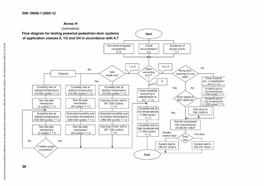
DIN 18650-1:2005-12
58
Annex H (normative)
Flow diagram for testing powered pedestrian door systems of application classes 0, 1/2 and 3/4 in accordance with 4.7
B55EB1B3C7662F79D1B59483A53B9F2F82C98BEEB7939DA445904AABD0F3108428F74B48ACF2599291A069AD4957C493EE60A3B134FC6C47B63934BB29CA3698646CE1EA0B764DE7542A090C10C67614B2A77833B6ACB991FA0939A71F8A5028ED09BC82AF8ED7AFBE5DB130A880AE3AA07E51B58B45EC499F5B
No
rmen
-Do
wn
load
-Beu
th-N
BN
Bu
reau
de
No
rmal
isat
ion
N.E
ntr
epri
se:
0880
.857
.592
-Kd
Nr.
1420
67-L
fNr.
3930
1510
01-2
008-
02-1
8 16
:09

DIN 18650-1:2005-12
59
Bibliography
[1] DIN 107, Building construction — Identification of right and left side
[2] DIN EN 982, Safety of machinery — Safety requirements for fluid power systems and their components — Hydraulics
[3] DIN EN 983, Safety of machinery — Safety requirements for fluid power systems and their components — Pneumatics
[4] DIN EN 1050:1997-01, Safety of machinery — Principles for risk assessment
[5] DIN EN ISO 12100-1, Safety of machinery — Basic concepts — General principles for design — Part 1: Basic terminology, methodology
[6] DIN EN ISO 12100-2, Safety of machinery — Basic concepts — General principles for design — Part 2: Technical principles
B55EB1B3C7662F79D1B59483A53B9F2F82C98BEEB7939DA445904AABD0F3108428F74B48ACF2599291A069AD4957C493EE60A3B134FC6C47B63934BB29CA3698646CE1EA0B764DE7542A090C10C67614B2A77833B6ACB991FA0939A71F8A5028ED09BC82AF8ED7AFBE5DB130A880AE3AA07E51B58B45EC499F5B
No
rmen
-Do
wn
load
-Beu
th-N
BN
Bu
reau
de
No
rmal
isat
ion
N.E
ntr
epri
se:
0880
.857
.592
-Kd
Nr.
1420
67-L
fNr.
3930
1510
01-2
008-
02-1
8 16
:09