DINAMICA - klimateknik.com · eine zyklische Redundanz von bis zu 6 Klimaanlagen zu steuern....
52
Condizionatori di precisione CLOSE CONTROL con ventilatori PLUG-FAN e soluzioni FREE-COOLING, DUAL COIL e DUAL FLUID. CLOSE CONTROL precision condi- tioners with PLUG-FAN and FREE- COOLING, DUAL COIL and DUAL FLUID solutions Präzisionsklimaanlagen für Server- räume mit PLUG-FAN und FREE- COOLING, DUAL COIL und DUAL FLUID Lösungen Climatiseurs de précision pour CLOSE CONTROL avec ventilateurs PLUG-FAN et solutions FREE-COOL- ING, DUAL COIL et DUAL FLUID DINAMICA NEW GENERATION SYSTEMS
Transcript of DINAMICA - klimateknik.com · eine zyklische Redundanz von bis zu 6 Klimaanlagen zu steuern....
Condizionatori di precisione CLOSE CONTROL con ventilatori PLUG-FAN e soluzioni FREE-COOLING, DUAL COIL e DUAL FLUID.
CLOSE CONTROL precision condi-tioners with PLUG-FAN and FREE-COOLING, DUAL COIL and DUAL FLUID solutions
Präzisionsklimaanlagen für Server-räume mit PLUG-FAN und FREE-COOLING, DUAL COIL und DUAL FLUID Lösungen
Climatiseurs de précision pour CLOSE CONTROL avec ventilateurs PLUG-FAN et solutions FREE-COOL-ING, DUAL COIL et DUAL FLUID
DINAMICA NEW GENERATION SYSTEMS
�
I condizionatori della serie DINAMICA sono da considerarsi come la soluzione più avanzata per il condizionamento in applicazioni tecnologiche, quali server farms, sale amplificatori dei broadca-ster UMTS e GSM, NOCs (Network Operation Centers), nel raffreddamento di racks di compu-ter, di sale di controllo, di equipaggiamenti elet-tronici di potenza, e in generale ovunque i carichi termici siano estremamente elevati.
Le unità DINAMICA sono state sviluppate con il gas ecologico R410A, che permette di ottenere benefici sull’ambiente grazie al basso impatto sull’effetto serra e prestazioni elevate dovute alle caratteristiche termodinamiche del gas.
Le unità DINAMICA ad espansione diretta conden-sate ad aria sono in grado di lavorare, nella linea TROPICAL LINE, fino a 52° C di temperatura aria esterna.
I pannelli incernierati in maniera tale da concedere l’accesso esclusivamente frontale, le più moderne soluzioni tecniche e i migliori componenti garantisco-no ai nostri condizionatori la massima versatilità e la più alta affidabilità nelle applicazioni “mission critical”.
Il telaio autoportante permette la completa rimozio-ne dei pannelli e la totale asportazione della porta incernierata, allo scopo di minimizzare il peso du-rante l’installazione. La doppia pannellatura (lamie-ra interna e pannello coibentato all’esterno) con-sente ottimi livelli di silenziosità in funzionamento.
Nelle applicazioni di precisione, il calore generato è principalmente asciutto e l'umidità introdotta è molto bassa, con conseguenti rapporti di calore sensibile intorno a 85-95%. Per questo motivo i nostri con-dizionatori forniscono un raffreddamento ad elevato rapporto di calore sensibile, aumentando l’efficien-za del sistema. Le sale da climatizzare si espando-no costantemente e i condizionatori devono essere flessibili nel soddisfare queste esigenze, tra cui il ri-posizionamento, l’aggiunta di accessori, ecc. I nostri condizionatori possono essere rilocati facilmente, poiché il peso è riducibile al minimo grazie all’utilizzo dell’alluminio e la possibilità di rimuovere i pannelli. Inoltre, è già prevista la foratura e il posizionamento per il montaggio di tutti gli accessori, riservando al cliente la facoltà di aggiungere eventuali ulteriori fun-zioni anche in un secondo tempo dall’acquisto. I nostri condizionatori sono altamente affidabili; tutta-via, chi progetta un'applicazione critica, deve presup-porre eventualità di guasto. Tutti i sistemi dovrebbero essere progettati avendo in mente in ogni caso la ri-dondanza di condizionamento, allo scopo di fornire il raffreddamento in maniera continua anche durante la manutenzione programmata. Tutti i nostri condi-zionatori sono già predisposti allo scopo di gestire una ridondanza ciclica fino a 6 condizionatori.
DINAMICA precision air conditioners are to be seen as the most advanced solution to all problems of air conditioning in all technologi-cal applications, like server farms, UMTS and GSM broadcasting power amplifiers, NOCs (Network Operation Centers), computer racks cooling, control rooms, power equipment, and in general wherever heat loads are critically high.
The DINAMICA units were developed using the ecological gas R410A which allows environmen-tal benefit thanks to its low impact on the green-house effect and high performance by virtue of the thermo-dynamic characteristics of this gas.
The DINAMICA direct expansion units with remote air condenser are able to work, in TROPICAL LINE range up to 52°C of outside air temperature
Front panels are hinged so that access is totally from the front; most modern technical solutions and best components grant our air conditioners maximum versatility and longest reliability for mis-sion critical applications.
Revolutionary self-containing frame allow all pan-els and front door to be removed, reducing total weight for easiest installation.Double panels (inner plate and insulated panel on the outside) allow optimal noiseless levels while functioning.
In precision applications, generated heat is mainly dry and input humidity is very low, with subsequent sensible heat ratio close to 85-95%. Having this in mind, we designed our air conditioners to supply an extremely high heat ratio, increasing overall system effi-ciency. Server and computer rooms are con-stantly expanding, and air conditioners have to be flexible into satisfying needs, such as conditioner relocation, accessories add-up, etc. Our air conditioners can be easily reposi-tioned, because weight is reduced to a mini-mum, thanks to the aluminum frame and to the panels removal system. Furthermore, all plates are already drilled for positioning and installation of all accessories, reserving the right for the customer to install further acces-sories at any time after the purchase. Our air conditioners are highly reliable; nevertheless a good designing pratice must assume some downtime. All systems have to be designed having in mind air conditioning redundancy, in order to supply continuous cooling during programmed maintenance. All our air condi-tioners are already preset in order to manage a cyclic redundancy of up to 6 units.
Descrizione Generale / General Features
�
DINAMICA Präzisionsklimageräte sind als die modernste Lösung zur Klimatisierung von ver-schiedensten Räumen anzusehen. Zu diesen Räumen gehören technische Applikationen wie zum Beispiel Serverfarmen, UMTS- und GSM Stationen, Rechenzentren, Computerräume, Schalträume und natürlich auch komforttech-nische Anwendungen und alle thermisch hoch-belasteten Räume.
Die Einheiten DINAMICA sind mit dem ökologi-schen Gas R410A entwickelt worden, das es dank der geringen Auswirkung auf den Treibhauseffekt ermöglicht Vorteile für die Umwelt zu erzielen und aufgrund der thermodynamischen Eigenschaften des Gases verbesserte Leistungen zu erreichen.
Die Einheiten DINAMICA mit Direktexpansion und Luftkondensation können in der Serie TROPICAL LINE bis zu 52° C Außentemperatur arbeiten.
Die Frontpaneele sind als Türen ausgeführt und ga-rantieren 100% Servicezugang ausschließlich von der Frontseite; modernste, technische Lösungen und die ausschließliche Verwendung von Quali-tätskomponenten garantieren eine zuverlässige und lange Verfügbarkeit bei kritischen Anwendungen.
Der selbsttragende Rahmen ermöglicht alle Pa-neele und die Fronttür zu demontieren, was eine einfache Installation ermöglicht. Der doppelwan-dige Aufbau reduziert Geräusche und Vibrationen auf ein Minimum.
In Präzisionsklimaanwendungen ist die Wärmelast meist trocken und der Feuchteeintrag in die Umluft meistens gering. Dies hat zur Konsequenz, dass die sensible Wärmelast zwischen 85 und 95% beträgt. Unsere Prä-zisionsklimageräte sind exakt für diesen Anwendungsfall konzipiert - mit einer sehr hohen sensiblen Kälteleistung wodurch die hohen interne Wärmelasten problemlos ab-geführt werden können. Server- und Computerräume vergrößern und verändern sich ständig. Deshalb werden hohe Ansprüche an die Klimageräte im Bezug auf verän-derte Aufstellflächen, Flexibilität oder Aufrüstmöglichkeiten gestellt. Unsere Präzisionsklimageräte können multifunk-tional eingesetzt werden. Durch das geringe Gewicht, dem stabilen Aluminiumrahmen und allseits abnehmbare Panelle können die Geräte einfach an andere Aufstellorte transportiert werden. Der nachträgliche Einbau von Zu-satzkomponenten ist bereits ab Werk vorgesehen und kann jeder Zeit am Aufstellort vorgenommen werden.Unsere Klimaanlagen sind äußerst zuverlässig; dennoch muss bei der Planung einer kritischen Anwendung ein möglicher Schadensfall berücksichtigt werden. Alle Sy-steme müssen mit Rücksicht auf die Redundanz der Kli-matisierung geplant werden, um auch während der plan-mäßigen Wartung eine durchgängige Kühlung zu bieten. Alle unsere Klimaanlagen sind schon dafür voreingestellt, eine zyklische Redundanz von bis zu 6 Klimaanlagen zu steuern.
Allgemeine Merkmale / Caractéristiques Générales
Les Armoires de conditionnement de la série DINAMICA sont considérées comme la solution la plus avancée pour tous les problèmes d’air conditionné en applications technologiques, comme les serveurs informatiques, les amplificateurs de puissance de diffusion UMTS et GSM, NOCs (Network Opération Center), refroidissement des ordinateurs, des salles de contrôle, des équipements électroniques de puissance, et en général partout ou les charges thermiques sont élevées.
Les unités DINAMICA ont été réalisées avec le gaz écologique R410A, qui permet d’obtenir des bénéfices sur l’environnement grâce au fai-ble impact sur l’effet de serre et aux rendements élevés dus aux caractéristiques thermodynami-ques du gaz.
Les unités DINAMICA à expansion directe condensées à air sont en mesure de fonctionner, dans la ligne TROPICAL LINE jusqu’à 52° C de température d’air extérieur.
Les panneaux de façade sont sur charnières de façon que l’accès soit totalement en face avant ; la solution technique la plus moderne et les meilleurs composants garantissent à nos armoires la polyvalence maximum et la plus haute fiabilité pour les applications les plus critiques.
Le chassis auto-portant révolutionnaire permet le démontage complèt des panneaux, et de la porte de façade, réduisant le poids total pour une instal-lation plus facile. Le doublage des panneaux (pan-neau intérieur et panneau insonorisé extérieur) réduit au minimum le bruit et les vibrations qui pourraient s’échapper de l’unité vers la pièce à climatiser.
En applications de précisions, la chaleur générée est principalement sèche et l’humidité introduite est très basse, avec un rapport de chaleur sensible d’environ 85-95%. Pour ce motif nos armoires fournissent un refroidissement avec un rapport de chaleur sensible élevé, augmentant l’efficacité du système. Les salles à climatiser étant en constante expansion, les armoires de conditionnement d’air doivent être flexibles pour pouvoir satisfaire aux exigences demandées, déplacement des armoires, ajout d’accessoires, etc.. Nos armoires de conditionnement d’air peuvent être aisément déplacées, car leur poids est réduit au minimum grace à l’utilisation de leur châssis en aluminium et à leur système de pan-neaux démontables. De plus, tout est déjà prévu pour le positionnement et l’installation de tous les accessoires, réservant la possibilité à l’installateur de pouvoir poser des accessoires éventuels après l’installation de l’armoi-re, sans modifications sur l’unité. Nos climatiseurs sont hautement fiables; toutefois, la personne qui conçoit une application critique doit penser à l’éventualité d’une panne. Tous les systèmes devraient être conçus en pensant, dans tous les cas, à la redondance de climati-sation, dans le but de fournir le refroidissement de façon continue même pendant la maintenance programmée. Tous nos climatiseurs ont été prédisposés pour gérer une redondance cyclique jusqu’à 6 climatiseurs.
�
Design innovativo e unità compatteInnovative design and compact unitsInnovatives design und Kompaktes GerätDesign innovant et unités compactes
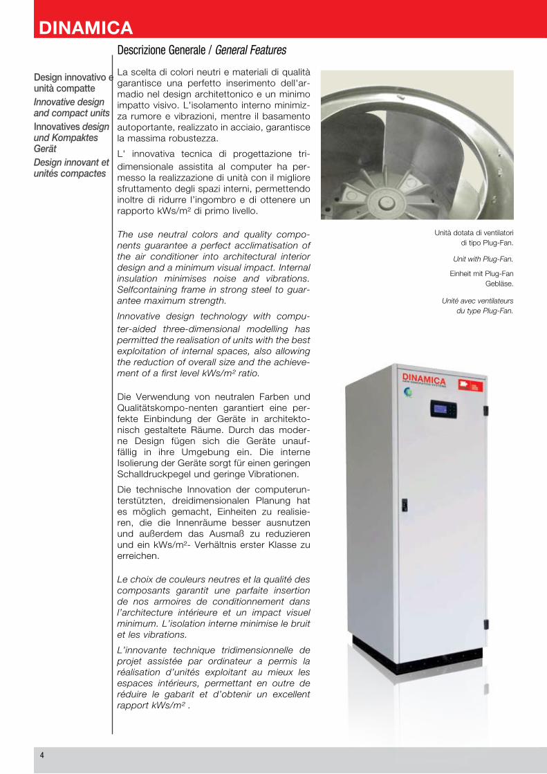
La scelta di colori neutri e materiali di qualità garantisce una perfetto inserimento dell'ar-madio nel design architettonico e un minimo impatto visivo. L'isolamento interno minimiz-za rumore e vibrazioni, mentre il basamento autoportante, realizzato in acciaio, garantisce la massima robustezza.
L' innovativa tecnica di progettazione tri-dimensionale assistita al computer ha per-messo la realizzazione di unità con il migliore sfruttamento degli spazi interni, permettendo inoltre di ridurre l’ingombro e di ottenere un rapporto kWs/m² di primo livello.
The use neutral colors and quality compo-nents guarantee a perfect acclimatisation of the air conditioner into architectural interior design and a minimum visual impact. Internal insulation minimises noise and vibrations. Selfcontaining frame in strong steel to guar-antee maximum strength.
Innovative design technology with compu-ter-aided three-dimensional modelling has permitted the realisation of units with the best exploitation of internal spaces, also allowing the reduction of overall size and the achieve-ment of a first level kWs/m² ratio.
Die Verwendung von neutralen Farben und Qualitätskompo-nenten garantiert eine per-fekte Einbindung der Geräte in architekto-nisch gestaltete Räume. Durch das moder-ne Design fügen sich die Geräte unauf-fällig in ihre Umgebung ein. Die interne Isolierung der Geräte sorgt für einen geringen Schalldruckpegel und geringe Vibrationen.
Die technische Innovation der computerun-terstützten, dreidimensionalen Planung hat es möglich gemacht, Einheiten zu realisie-ren, die die Innenräume besser ausnutzen und außerdem das Ausmaß zu reduzieren und ein kWs/m²- Verhältnis erster Klasse zu erreichen.
Le choix de couleurs neutres et la qualité des composants garantit une parfaite insertion de nos armoires de conditionnement dans l’architecture intérieure et un impact visuel minimum. L’isolation interne minimise le bruit et les vibrations.
L’innovante technique tridimensionnelle de projet assistée par ordinateur a permis la réalisation d’unités exploitant au mieux les espaces intérieurs, permettant en outre de réduire le gabarit et d’obtenir un excellent rapport kWs/m² .
Descrizione Generale / General Features
Unità dotata di ventilatori di tipo Plug-Fan.
Unit with Plug-Fan.
Einheit mit Plug-FanGebläse.
Unité avec ventilateursdu type Plug-Fan.
�
Facilemanutenzione
Easymaintenance
EinfacheWartung
Facilitéde maintenance
In fase di progettazione delle unità DINAMICA è stata data particolare importanza alla necessità di semplificare le normali operazioni di manuten-zione; sono realizzate infatti sezioni separate per un razionale accesso alle aree del condizionatore secondo le necessità del manutentore.
In the design phase of the DINAMICA units, particular importance was given to the necessity of simplifying ordinary maintenance; in fact sepa-rate sections were realised for rational access to the parts of the air conditioner according to the needs of maintenance personnel.
Während der Entwicklungsphase der DINAMICA-Einheiten wurde der Vereinfachung der War-tungs-arbeiten besondere Aufmerksamkeit gewidmet; es wurden nämlich getrennte Sektionen realisiert, um je nach Bedarf des Wartungsarbeiters einen ratio-nalen Zugang zu den Bereichen der Klimaanlage zu ermöglichen.
Lors de la phase de projet des unités DINAMICA, la nécessité de simplifier les opérations normales d’entretien a été considérée avec une importance particulière; en effet, des sections séparées ont été créées pour accéder de façon rationnelle aux zones du climatiseur en fonction des nécessités de la personne préposée à l’entretien.
Applicazione in ambiente dedicato alle telecomunicazioni.
Application in thetelecommunications field.
Einsatz in für die Telekommunikation bestimmtem Bereich.
Application en milieu dédié aux télé-communications.
Allgemeine Merkmale / Caractéristiques Générales
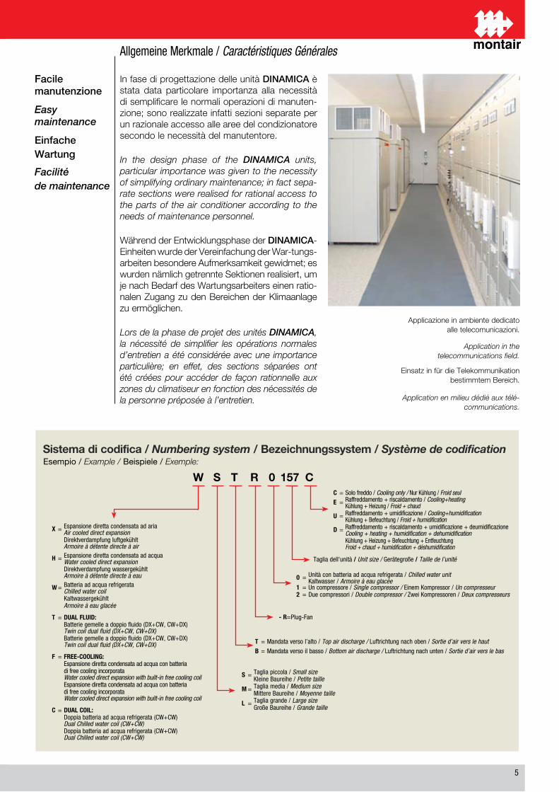
W S T R 0 157 CC = Solo freddo / Cooling only / Nur Kühlung / Froid seul
E = Raffreddamento + riscaldamento / Cooling+heating Kühlung + Heizung / Froid + chaud
U = Raffreddamento + umidificazione / Cooling+humidification Kühlung + Befeuchtung / Froid + humidification
D = Raffreddamento + riscaldamento + umidificazione + deumidificazione Cooling + heating + humidification + dehumidification Kühlung + Heizung + Befeuchtung + Entfeuchtung Froid + chaud + humidification + déshumidification
Taglia dell'unità / Unit size / Gerätegroße / Taille de l’unité
0 = Unità con batteria ad acqua refrigerata / Chilled water unit Kaltwasser / Armoire à eau glacée1 = Un compressore / Single compressor / Einem Kompressor / Un compresseur2 = Due compressori / Double compressor / Zwei Kompressoren / Deux compresseurs
T = Mandata verso l’alto / Top air discharge / Luftrichtung nach oben / Sortie d’air vers le haut
B = Mandata verso il basso / Bottom air discharge / Luftrichtung nach unten / Sortie d’air vers le bas
S = Taglia piccola / Small size Kleine Baureihe / Petite taille
M = Taglia media / Medium size Mittere Baureihe / Moyenne taille
L = Taglia grande / Large size Große Baureihe / Grande taille
X = Espansione diretta condensata ad aria Air cooled direct expansion Direktverdampfung luftgekühlt Armoire à détente directe à air
H = Espansione diretta condensata ad acqua Water cooled direct expansion Direktverdampfung wassergekühlt Armoire à détente directe à eau
W = Batteria ad acqua refrigerata Chilled water coil Kaltwassergekühlt Armoire à eau glacée
T = DUAL FLUID: Batterie gemelle a doppio fluido (DX+CW, CW+DX) Twin coil dual fluid (DX+CW, CW+DX) Batterie gemelle a doppio fluido (DX+CW, CW+DX) Twin coil dual fluid (DX+CW, CW+DX)
F = FREE-COOLING: Espansione diretta condensata ad acqua con batteria di free cooling incorporata Water cooled direct expansion with built-in free cooling coil Espansione diretta condensata ad acqua con batteria di free cooling incorporata Water cooled direct expansion with built-in free cooling coil
C = DUAL COIL: Doppia batteria ad acqua refrigerata (CW+CW) Dual Chilled water coil (CW+CW) Doppia batteria ad acqua refrigerata (CW+CW) Dual Chilled water coil (CW+CW)
Esempio / Example / Beispiele / Exemple:
- R = Plug-Fan
Sistema di codifica / Numbering system / Bezeichnungssystem / Système de codification
�
Versioni disponibili / Available versions
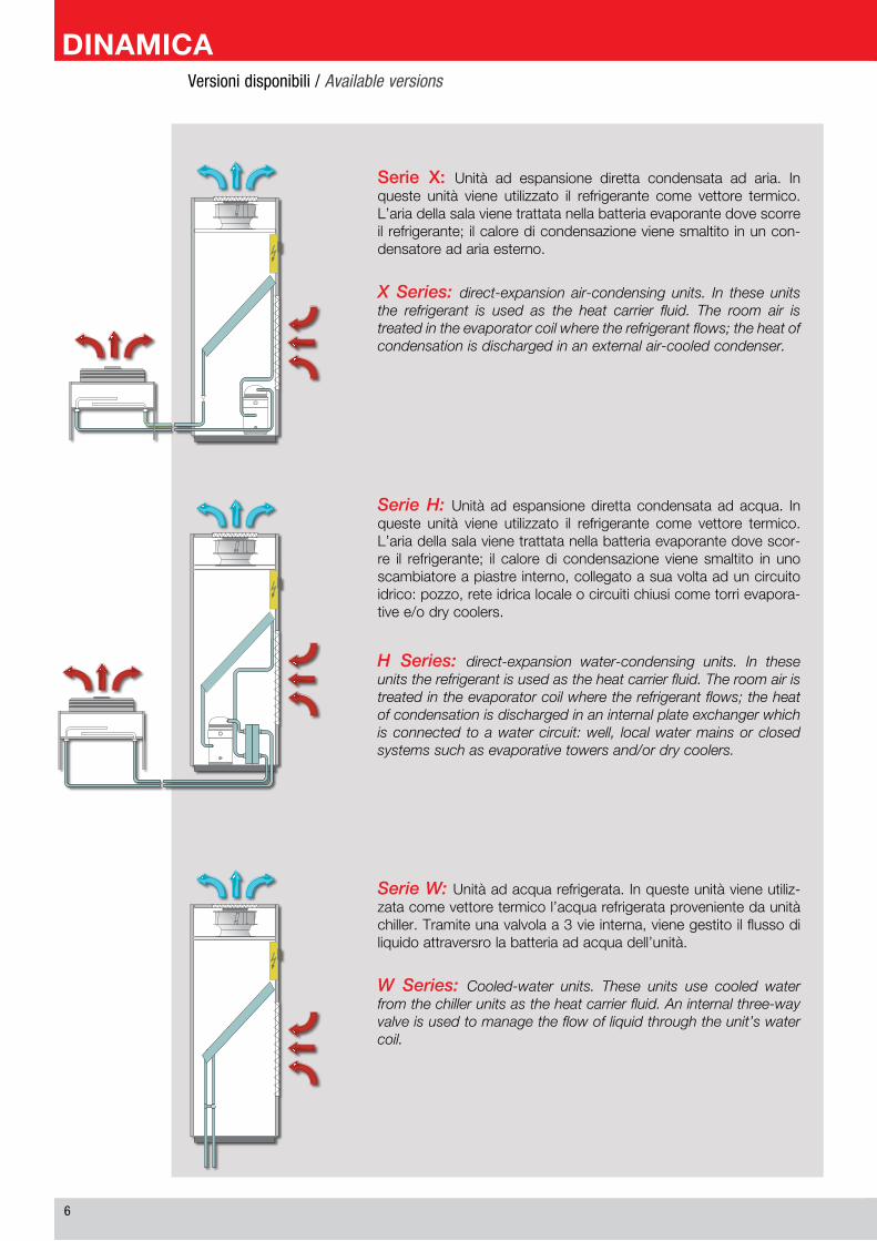
Serie W: Unità ad acqua refrigerata. In queste unità viene utiliz-zata come vettore termico l’acqua refrigerata proveniente da unità chiller. Tramite una valvola a 3 vie interna, viene gestito il flusso di liquido attraversro la batteria ad acqua dell’unità.
W Series: Cooled-water units. These units use cooled water from the chiller units as the heat carrier fluid. An internal three-way valve is used to manage the flow of liquid through the unit’s water coil.
Serie H: Unità ad espansione diretta condensata ad acqua. In queste unità viene utilizzato il refrigerante come vettore termico. L’aria della sala viene trattata nella batteria evaporante dove scor-re il refrigerante; il calore di condensazione viene smaltito in uno scambiatore a piastre interno, collegato a sua volta ad un circuito idrico: pozzo, rete idrica locale o circuiti chiusi come torri evapora-tive e/o dry coolers.
H Series: direct-expansion water-condensing units. In these units the refrigerant is used as the heat carrier fluid. The room air is treated in the evaporator coil where the refrigerant flows; the heat of condensation is discharged in an internal plate exchanger which is connected to a water circuit: well, local water mains or closed systems such as evaporative towers and/or dry coolers.
Serie X: Unità ad espansione diretta condensata ad aria. In queste unità viene utilizzato il refrigerante come vettore termico. L’aria della sala viene trattata nella batteria evaporante dove scorre il refrigerante; il calore di condensazione viene smaltito in un con-densatore ad aria esterno.
X Series: direct-expansion air-condensing units. In these units the refrigerant is used as the heat carrier fluid. The room air is treated in the evaporator coil where the refrigerant flows; the heat of condensation is discharged in an external air-cooled condenser.
�
Versioni disponibili / Available versions Verfügbaren Versionen / Versions disponibles
W Serie: Kaltwassergerät. Bei diesen Geräten wird Wasser, das normalerweise von einem Chiller kommt, zur Wärmeübertragung verwendet. Über ein internes 3-Wege-Ventil wird die Flüssigkeit durch den Wasser-Wärmetauscher des Geräts geleitet.
Série W: Unité à eau réfrigérée. Dans ces unités, on utilise l’eau réfrigérée provenant d’un chiller comme vecteur thermique. À tra-vers une vanne interne à 3 voies, on gère le flux de liquide à travers la batterie à eau de l’unité.
H Serie: Wassergekühltes Gerät mit direkter Verdampfung. Die Raumluft wird im Verdampfer, in dem das Kältemittel fließt, aufberei-tet. Die durch die Kondensation entstehende Wärme wird über einen internen Plattenwärmetauscher abgeleitet, der seinerseits an einem Wasserkreislauf mit Brunnenwasser, Wasserleitung oder geschlos-senen Wasserkreisläufen wie beispielsweise Verdampfertürme und/oder Dry Cooler angeschlossen ist.
Série H: Unité à expansion directe condensée à eau. Dans ces unités, on utilise le réfrigérant comme vecteur thermique. L’air de la salle est traité dans la batterie évaporante où s’écoule le réfrigérant ; la chaleur due à la condensation est éliminée dans un échangeur à plaques interne, raccordé, à son tour, à un circuit hydrique, de puits, au réseau hydrique local ou à des circuits fermés comme des tours d’évaporation et/ou des dry coolers.
X Serie: Luftgekühltes Gerät mit direkter Verdampfung. Bei die-sen Geräten wird das Kältemittel als Wärmeträger eingesetzt.
Die Raumluft wird im Verdampfer, in dem das Kältemittel fließt, aufbereitet; Die Kondensationswärme wird über den Frischluft- Kondensator abgeleitet.
Série X: Unité à expansion directe condensée à air. Dans ces unités, on utilise le réfrigérant comme vecteur thermique. L’air de la salle est traité dans la batterie évaporante où s’écoule le gaz réfrigérant ; la chaleur de condensation est éliminée grâce à un condensateur à air, externe.
�
Serie T - DUAL FLUID: si caratterizza dalla pre-senza di due modalità di funzionamento distinte, facenti capo a due diverse batterie di raffred-damento: una ad espansione diretta ed una ad acqua refrigerata. La priorità può essere arbitra-riamente attribuita a qualsiasi delle due modalità, con la commutazione automatica (o manuale selezionabile da ingresso digitale) in caso di allar-me, anomalie o semplice manutenzione ordinaria. In particolare, quando la priorità è attribuita al cir-cuito ad acqua refrigerata, un sensore controlla la temperatura dell’acqua erogata dal chiller. Quanto essa dovesse salire oltre una soglia preimpostata, il circuito ad acqua refrigerata viene escluso (chiu-dendo la valvola 3 vie e permettendo al chiller di ricircolare su se stesso) garantendo al contempo il carico termico tramite l’accensione del circuito ad espansione diretta dell’unità Close Control.
Nel caso in cui la priorità sia attribuita al circuito ad espansione diretta, la batteria ad acqua refri-gerata è generalmente collegata ad una sorgente di acqua di emergenza. In questo caso, su richie-sta del cliente, la terza via viene chiusa così da ottenere un funzionamento on/off modulante e minimizzare il consumo di acqua di emergenza a perdere, sino al ripristino della condizione di funzionamento normale ad espansione diretta. La commutazione sul circuito di emergenza è gestita automaticamente dal microprocessore in caso di anomalia su uno (per le unità ad un circuito) o entrambi i circuiti frigoriferi del Close Control, oppure quando la temperatura ambientale doves-se superare una soglia preimpostata. Le due modalità possono essere comunque commutate manualmente tramite un ingresso digitale, per le operazioni di manutenzione e, nel caso di modalità a priorità con acqua refrigerata, l’ingresso digitale di commutazione può essere interfacciato con l’allarme generale proveniente dal chiller.
T Serie - DUAL FLUID: these units are cha-racterized by the presence of two distinct opera-ting modes, using two different cooling coils: one direct-expansion coil and one cooled-water coil. The priority can be attributed arbitrarily to either of the two modes, with automatic switching (or manual switching which can be selected by a digital input) in case of alarm, anomalies or sim-ple routine maintenance. In particular, when the priority is attributed to the cooled-water circuit, a sensor controls the temperature of the water supplied by the chiller. If this temperature should rise above the preset threshold, the cooled water circuit is excluded (by closing the 3-way valve and allowing the chiller to recirculate on itself) while at the same time guaranteeing the thermal load by switching on the direct-expansion circuit of the Close Control unit.
If the priority is attributed to the direct-expan-sion circuit, the cooled-water coil is usually connected to an emergency water source. In this case, on the customer’s request, the third way is closed so as to obtain a modulating on/off operation and minimize the consumption of disposable emergency water until restoration of the normal direct-expan-sion operation. The switching to the emer-gency circuit is managed automatically by the microprocessor in case of anomalies on one (for the one-circuit units) or both the cooling circuits of the Close Control, or when the environmental temperature exceeds a preset threshold. The two modes can in any case be switched manually by means of a digital input, for maintenance operations and, in the case of the cooled-water priority mode, the digital switching input can be interfaced with the general alarm coming from the chiller.
Serie T - DUAL FLUID: Unità dotate di due sistemi separati di raffreddamento ad attivazione non contemporanea: uno PRIMARIO ad acqua refrigerata (CW) asservito ad un chiller presente in sito ed uno SECONDARIO ad espansione diretta (DX) ovvero anche di back-up. Questo tipo di unità è particolarmente indicata nei sistemi in cui è richiesta particolare AFFIDABILITA’, SICUREZZA e RIDONDANZA del sistema di condizionamento.
T Series - DUAL FLUID: Units equipped with two separate cooling systems with non-simultaneous activation: one PRIMARY system with cooled water (CW) controlled by a chiller on site and one SECONDARY system with direct expansion (DX) which also acts as a back-up. This type of unit is especially suited for systems which require particular RELIABILITY, SAFETY and REDUNDANCY of the air-conditioning system.
Versioni disponibili / Available versions
�
T Serie - DUAL FLUID: Zeichnet sich durch zwei unterschiedliche Betriebsarten aus, die zu zwei unterschiedlichen Wärmetauschern führen, einen mit direkter Verdampfung und der andere mit Kaltwasser.
Durch die automatische (oder über den digitalen Eingang manuell wählbare) Umschaltung kann bei Alarm, Störungen oder normaler Wartung jeder der beiden Betriebsarten die Priorität gegeben werden. Insbesondere bei Zuweisung der Priorität an den Kaltwasserkreislauf kontrolliert ein Fühler die Temperatur des vom Chiller abgegebenen Wassers.
Steigt diese über einen voreingestellten Wert, wird der Kaltwasserkreislauf durch Schließen des 3-Wege-Ventils abgetrennt. Dadurch erfolgt der Umlauf im Chiller, gleichzeitig wird der Kältebedarf durch das Einschalten des Kreislaufs mit direkter Verdampfung am Gerät Close Control garantiert.
Ist die Priorität dem Kreislauf mit direkter Verdampfung zugewiesen, ist der Kaltwassersatz normalerweise an eine Notwasserquelle angeschlossen. In die-sem Fall wird, auf Wunsch des Kunden, die dritte Leitung geschlossen, damit ein modulierender ON/OFFBetrieb vorliegt und der Verbrauch an Notwasser minimiert wird, bis der normale Betrieb mit direkter Verdampfung wieder aufgenommen werden kann.
Das Umschalten auf den Notkreislauf wird vom Mikroprozessor automatisch ausgeführt, wenn an einem (bei Geräten mit einem Kreislauf) oder beiden Kältekreisläufen der Close Control Störungen auf-treten, oder wenn die Raumtemperatur einen vor-eingestellten Wert übersteigt, ein Anzeichen dafür, dass der Kreislauf mit direkter Verdampfung nicht wirksam arbeitet. Die beiden Betriebsarten können jedoch für Wartungsarbeiten über einen digitalen Eingang manuell gewählt werden. Bei Priorität des Kaltwasserbetriebs kann der digitale Schalteingang mit dem allgemeinen Alarm, der vom Chiller kommt, verknüpft werden.
Série T - DUAL FLUID: elle se caractérise par la présence de deux modalités de fonctionnement distinctes, liées à deux différentes batteries de refroidissement : une à expansion directe et une à eau réfrigérée.
La priorité peut être arbitrairement attribuée à une quelconque des deux modalités, avec la commu-tation automatique (ou manuelle, que l’on peut sélectionner à partir d’une entrée numérique) en cas d’alarme, d’anomalies ou de simple entretien ordinaire. En particulier, quand la priorité est attri-buée au circuit à eau réfrigérée, un capteur contrôle la température de l’eau distribuée par le chiller.
Si elle augmente au-delà d’un seuil préconfiguré, le circuit à eau réfrigérée est exclu (en fermant la vanne à 3 voies et en permettant au chiller de recir-culer sur lui-même), et en garantissant en même temps la charge thermique avec l’allumage du cir-cuit à expansion directe de l’unité Close Control.
Si la priorité est attribuée au circuit à expansion direc-te, la batterie à eau réfrigérée est généralement rac-cordée à une source d’eau de secours. Dans ce cas, sur demande du client, la troisième voie est fermée afin d’obtenir un fonctionnement on/off modulant et de minimiser la consommation d’eau de secours à perdre, jusqu’au rétablissement de la condition de fonctionnement normal à expansion directe.
La commutation sur le circuit de secours est gérée automatiquement par le microprocesseur en cas d’anomalie sur un (pour les unités à un cir-cuit) ou sur les deux circuits frigorifiques du Close Control, ou bien quand la température ambiante dépasse un seuil préconfiguré. Les deux moda-lités peuvent être commutées manuellement à travers une entrée numérique, en cas d’entretien, ou bien dans le cas de la modalité à priorité avec eau réfrigérée, l’entrée numérique de commuta-tion peut être interfacée avec l’alarme générale provenant du chiller.
T Serie - DUAL FLUID: Die Geräte verfügen über zwei getrennte Kühlsysteme, die nicht gleichzeitig betrieben werden können. Ein PRIMÄRSYSTEM mit Kaltwasser CW, über einen vor Ort vorhandenen Chiller gesteuert, und ein SEKUNDÄRSYSTEM mit Direktverdampfung DX oder auch als BACK-UP. Diese Geräteart ist besonders für Systeme geeignet, bei denen ZUVERLÄSSIGKEIT, SICHERHEIT und REDUNDANZ der Klimaanlage besonders wichtig sind.
Série T - DUAL FLUID: Unités équipées de deux systèmes séparés de refroidissement à activation non en même temps : un PRIMAIRE à eau réfrigérée (CW), asservi à un chiller présent sur place et un SECONDAIRE à expansion directe (DX) c’est-à-dire aussi de BACK-UP. Ce type d’unité est particulièrement indiqué dans les systèmes où la FIABILITÉ, la SÉCURITÉ et la REDONDANCE du sys-tème de conditionnement sont particulièrement nécessaires.
Versioni disponibili / Available versions Verfügbaren Versionen / Versions disponibles
10
Serie F - FREE-COOLING: è la soluzione stu-diata per massimizzare il risparmio energetico. L’unità Close Control in condizioni normali lavora come un’unità ad espansione diretta condensata ad acqua con dry cooler (funzionamento DX). In funzione della temperatura esterna una valvola pressostatica regola la pressione di condensa-zione e, al raggiungimento di un determinato valore, apre il deflusso di parte della portata in una batteria di raffreddamento posta in serie alla batteria ad espansione diretta (funzionamento MISTO). Al raggiungimento di una impostata temperatura esterna energeticamente ottimale, il compressore si spegne e la valvola fa defluire l’intero ammontare della portata nella batteria di raffreddamento ad acqua (funzionamento CX). La commutazione è gestita automaticamente dal microprocessore, che garantisce un corretto raf-freddamento dell’ambiente e il massimo rispar-mio energetico. In caso di condizioni climatiche invernali particolarmente severe, una seconda valvola riduce o azzera l’afflusso di acqua in bat-teria così da scongiurare la formazione di brina o temperature di mandata eccessivamente basse.
F Series - FREE-COOLING: This is the solu-tion designed to maximize energy savings. The Close Control unit under normal conditions works as a direct-expansion water-condens-ing unit with dry cooler (DX operation). Based on the external temperature, a pressure valve regulates the condensation pressure and, when it reaches a certain value, opens the outflow of part of the flow into a cooling coil located in series with the direct-expansion coil (MIXED operation). When an energeti-cally optimized set external temperature is reached, the compressor switches off and the valve sends the entire flow to the water-cool-ing coil (CX operation). The switching is man-aged automatically by the microprocessor, which guarantees the proper cooling of the environment and maximum energy savings. In the case of particularly severe winter climatic conditions, a second valve reduces or zeroes the flow of water in the coil so as to prevent the formation of frost or excessively low deliv-ery temperatures.
Serie F - FREE-COOLING: Unità dotate di due sistemi sepa-rati di raffreddamento, uno PRIMARIO ad espansione diretta (DX) ed uno SECONDARIO ad acqua refrigerata (CW). Il microprocesso-re, di cui sono dotate le unità, gestisce 3 modalità di funzionamen-to: solo DX, MISTO e CX. In funzione della temperatura esterna, esso permette di massimizzare il risparmio energetico gestendo in maniera intelligente le tre modalità di funzionamento. Questo tipo di unità è particolarmente indicata nei sistemi in cui è richiesta par-ticolare attenzione all’EFFICIENZA ed al RISPARMIO ENERGETICO dell’intero sistema di condizionamento.
F Series - FREE-COOLING: Units equipped with two separate cooling systems, a PRIMARY system with direct expansion (DX) and a SECONDARY system with cooled water (CW). The units are equipped with a microprocessor which manages 3 operating modes: DX only, MIXED and CX. Based on the external tempera-ture, it allows to maximize the energy savings by intelligently mana-ging the three operating modes. This type of unit is especially suited for systems which require particular RELIABILITY and ENERGY SAVINGS for the entire air-conditioning system.
Versioni disponibili / Available versions
11
F Serie - FREE-COOLING: Die Lösung, die für maximale Energieeinsparung entwickelt wurde. Das Basisgerät Close Control arbeitet abhängig von der Außentemperatur mit direkter Wasserverdampfung des Dry Coolers.
Ein Druckventil steuert den Kondensationsdruck und öffnet gleichzeitig den teilweisen Abfluss in einen Verdampfer, der nach dem Wärmetauscher mit direkter Verdampfung angebracht ist. Sind die optimalen Bedingungen oder eine einge-stellte Außentemperatur erreicht, schaltet sich der Kompressor aus und das Ventil lässt die gesamte Durchflussmenge in den wasserbetrie-benen Verdampfer ablaufen. Die Umschaltung erfolgt transparent und automatisch, die Umgebungsparameter werden ständig über-wacht, damit durch eine wirksame Raumkühlung die gewünschte Energieeinsparung immer gewährleistet ist. Wenn die Wetterbedingungen im Winter hingegen besonders streng sind, wird der Wasserdurchfluss in den Verdampfer durch ein zweites Ventil vermindert oder verhin-dert, damit sich kein Reif bilden kann oder die Zulauftemperaturen zu niedrig werden.
Série F - FREE-COOLING: c’est la solution conçue pour maximiser l’économie d’énergie. L’unité Close Control travaille, en conditions normales, comme une unité à expansion directe condensée à eau avec dry cooler (fonctionnement DX).
En fonction de la température externe, une vanne pressostatique règle la pression de condensation et, quand une valeur déterminée est atteinte, elle ouvre l’écoulement d’une partie du débit dans une batterie de refroidissement placée en série avec la batterie à expansion directe (fonctionnement MIXTE). Quand la tem-pérature externe configurée, énergétiquement optimale, est atteinte, le compresseur s’éteint et la vanne fait écouler tout le débit dans la batterie de refroidissement à eau (fonctionnement CX). La commutation est gérée automatiquement par le microprocesseur qui garantit un refroidis-sement ambiant correct et l’économie d’énergie maximale Dans le cas de conditions climatiques de l’hiver particulièrement rigides, une deuxième vanne réduit ou porte à zéro l’afflux de l’eau dans la batterie, afin d’éviter la formation de givre ou de températures de refoulement exces-sivement basses.
F Serie - FREE-COOLING: Geräte, die mit zwei unter-schiedlichen Kühlsystemen ausgestattet sind, eines mit direkter Verdampfung DX - PRIMÄRSYSTEM, und eines mit Kaltwasser CW - SEKUNDÄRSYSTEM. Durch das Funktionsprinzip kann die Raumwärme abgeleitet werden, wenn die Frischlufttemperatur niedriger als die des zu kühlenden Raumes ist. Mit dem einge-bauten Mikroprozessor der Geräte können 3 Betriebsarten gere-gelt werden: nur DX, GEMISCHT und CX. Diese Geräteart ist besonders geeignet für Systeme, bei denen WIRKSAMKEIT und ENERGIEEINSPARUNG der Klimaanlage besonders wichtig sind.
Série F - FREE-COOLING: Unités équipées de deux systè-mes séparés de refroidissement, un PRIMAIRE à expansion directe (DX) , et un SECONDAIRE à eau réfrigérée (CW). Le microproces-seur, dont sont équipées les unités, gère 3 modalités de fonction-nement : seulement DX, MIXTE et CX. En fonction de la température externe, il permet de maximiser l’économie d’énergie en gérant de manière intelligente les trois modalités de fonctionnement. Ce type d’unité est particulièrement indiqué dans les systèmes où il faut faire particulièrement attention au RENDEMENT et à l’ÉCONOMIE D’ÉNERGIE de tout le système de conditionnement.
Versioni disponibili / Available versions Verfügbaren Versionen / Versions disponibles
1�
Serie C - DUAL COIL: si caratterizza dalla presenza di due batterie ad acqua refrigerata che possono essere utilizzate in alternativa o in contemporanea. Ci sono diversi scenari possibili, che possono essere previsti in funzione delle esigenze della clientela.
Batterie in alternativa, entrambe collegate a due diversi circuiti di acqua refrigerata. In questo caso vi sarà un circuito primario e un circuito di emergenza secondario, identici nelle potenzialità, e che possono essere commutati l’uno sull’altro in presenza di allarme. In questo caso i due chiller attueranno una politica di ridondanza attiva 1+1. Il microprocessore di regolazione potrà comunque autonomamente attivare entrambe le batterie nel caso in cui la temperatura ambientale dovesse salire oltre una soglia preimpostata, sfruttando la seconda batteria anche come riserva attiva in ausilio.
Batteria ad acqua refrigerata prioritaria, seconda batteria di emergenza collegata ad un serba-toio interrato o acqua di acquedotto a perdere. Questo scenario è analogo a quello visto in prece-denza per la Serie T; anche in questo caso la com-mutazione avviene in automatico su temperatura, o manualmente su ingresso digitale.
Flow saving. Le due batterie della linea C hanno una potenza frigorifera combinata pari ad una batteria della Serie W; in fase di funzionamento par-zializzato ad esempio al 50% della propria capacità frigorifera, la Serie W richiede comunque una portata d’acqua di progetto costante pari a quella nominale. In questo caso può essere conveniente ricorrere ad un Close Control della Serie C per risparmiare por-tata e energia sulle pompe di circolazione, potendo disattivare una delle due batterie in serie.
C Series - DUAL COIL: These units are character-ized by the presence of two cooled-water coils that can be used alternatively or simultaneously. There are various possible scenarios which can be pro-vided for based on the customer’s needs.
Alternative coils, both connected to two differ-ent cooled-water circuits. In this case there will be a primary circuit and a secondary emergency circuit, identical in power, which can be switched from one to another in case of alarm. In this case the two chillers implement a 1+1 redundancy. The regulation microprocessor can in any case autonomously activate both the coils in the event the environmental temperature should rise above the preset threshold, using the second coil as an active auxiliary reserve.
The cooled-water coil as the priority, and the second emergency coil connected to an under-ground tank or open water system. This scenario is analogous to that seen previously for the T Series; in this case as well, the switching occurs automati-cally based on temperature, or manually based on digital input.
Flow saving. The two coils of the C line have a combined cooling power equal to that of one coil of the W Series; during partialized operation, at 50% of its cooling capacity for example, the W Series in any case requires a constant design flow of water equal to the nominal flow. In this case it may be convenient to use a Close Control of the C Series to save flow and energy on the circulation pumps, being able to deactivate one of the two coils in series.
Serie C - DUAL COIL: Unità dotate di due circuiti per il raf-freddamento, entrambi ad acqua refrigerata e indipendenti l’uno dall’altro. Tali circuiti sono asserviti a 2 chillers presenti sul sito completamente indipendenti. Questo tipo di unità è particolarmen-te indicata nei sistemi in cui è richiesta particolare AFFIDABILITA’, SICUREZZA e RIDONDANZA del sistema di condizionamento.
C Series - DUAL COIL: Units equipped with two cooling circuits, which are both cooled-water circuits and independent from one another. These circuits are controlled by 2 completely independent chillers present on site. This type of unit is especially suited for systems which require particular RELIABILITY, SAFETY and REDUNDANCY of the air-conditioning system.
Versioni disponibili / Available versions
1�
C Serie - DUAL COIL: Zeichnet sich durch zwei Kaltwassersätze aus, die alternativ oder gleichzei-tig verwendet werden können. Es gibt verschiedene Möglichkeiten, die je nach Kundenbedürfnis vorgese-hen werden können.
Alternative Kaltwassersätze, beide an zwei unter-schiedliche Kaltwasserkreisläufe angeschlossen. In diesem Fall gibt es einen Primärkreislauf und einen Sekundärkreislauf für den Notfall, mit gleicher Leistung, die bei einem Alarm auf den anderen umgeschaltet wer-den können. In diesem Fall arbeiten die Chiller in aktiver Redundanz 1+1. Der Mikroprozessor für die Steuerung kann beide Kaltwassersätze selbständig aktivieren, wenn die Raumtemperatur über einen eingestellten Wert steigt, dabei wird der zweite Kaltwassersatz auch als aktive Hilfsreserve genutzt.
Kaltwassersatz mit Priorität, zweiter Kaltwassersatz für den Notfall an einen unterirdischen Speicher oder Leitungswasser angeschlossen. Diese Lösung ist analog zu der, die zuvor bei der Serie T beschrieben wurde. Auch in diesem Fall erfolgt die Umschaltung automatisch aufgrund der Temperatur, oder manuell über den digitalen Eingang.
Flow Saving. Die beiden Kaltwassersätze der Leitung C besitzen eine gemeinsame Kühlleistung, die einem Wärmetauscher der Serie W entspricht. Arbeitet die Serie W jedoch mit 50% ihrer Kühlleistung, benötigt sie dennoch einen konstanten Wasserdurchfluss, der dem Nennwert entspricht. In diesem Fall kann es angebracht sein, auf ein Gerät Close Control der Serie C zurückzu-greifen, um Wasser und Energie der Umwälzpumpen zu sparen, in dem man einen der beiden hintereinander liegenden Wärmetauscher deaktiviert.
Série C - DUAL COIL: se caractérise par la présence de deux batteries à eau réfrigérée qui peuvent être utilisées en alternative ou en même temps. Il y a plu-sieurs scénarios possibles qui peuvent être prévus en fonction des exigences de la clientèle.
Batteries en alternative, toutes les deux raccordées à deux circuits différents d’eau réfrigérée. Dans ce cas, il y aura un circuit primaire et un circuit secondaire de secours, identiques comme potentiel et qui peuvent être commutés l’un sur l’autre, en présence d’alarme. Dans ce cas, les deux chillers réaliseront une politique de redondance active 1+1. Le microprocesseur de réglage pourra de manière autonome activer les deux batteries si la température ambiante augmente au-delà d’un seuil préconfiguré, en exploitant la deuxième bat-terie comme réserve active auxiliaire.
Batterie à eau réfrigérée prioritaire, deuxième batterie de secours raccordée à un réservoir enterré ou à l’eau de puits à perdre. Ce scénario est semblable au précédent pour la Série T ; dans ce cas aussi, la commutation se fait en automati-que sur la température ou manuellement sur l’en-trée numérique.
Flow saving. Les deux batteries de la ligne C ont une puissance frigorifique combinée, équivalente à une batterie de la Série W ; toutefois, la Série W, quand elle fonctionne à 50% de sa propre capa-cité frigorifique, demande un débit d’eau constant équivalent au débit nominal. Dans ce cas, il peut être intéressant de recourir à un Close Control de la Série C pour économiser débit et énergie sur les pompes de circulation, en désactivant une des deux batteries en série.
C Serie - DUAL COIL: Für diese Geräte sind zwei Kühlkreisläufe verfügbar, beide mit Kaltwasser und voneinander unabhängig. Diese Kreisläufe werden durch 2 vor Ort vorhandene, vollständig unabhängige Chiller versorgt. Diese Geräteart ist besonders geeig-net für Systeme, bei denen ZUVERLÄSSIGKEIT, SICHERHEIT und REDUNDANZ der Klimaanlage besonders wichtig sind.
Série C - DUAL COIL: Unités équipées de deux circuits pour le refroidissement, tous deux à eau réfrigérée et indépendants l’un de l’autre. Ces circuits sont asservis à 2 chillers présents sur le site et complètement indépendants. Ce type d’unité est particuliè-rement indiqué dans les systèmes où il faut faire particulièrement attention à la FIABILITÉ, à la SÉCURITÉ et à la REDONDANCE du système de conditionnement.
Versioni disponibili / Available versions Verfügbaren Versionen / Versions disponibles

1�
Caratteristiche Generali / General Features
Il compressore Scroll consiste di due involute o spirali di Archimede. Una spirale è posizionata internamen-te all'altra per formare una serie di cavità a forma di tasche. Durante la compressione, la spirale superio-re rimane stazionaria e quella inferiore, montata ec-centricamente sull'albero di azionamento, descrive un’orbitale piuttosto che un movimento rotativo sem-plice. In questo modo il refrigerante è indotto in due grandi tasche diametralmente opposte che si chiu-dono progressivamente mentre raggiungono il cen-tro della spirale, comprimendo così il gas. Quando al centro della spirale il gas raggiunge la pressione di scarico, esso viene rilasciato attraverso una porta di scarico nel centro della spirale fissa. Ogni giro della spirale tutte le tasche sono simultaneamente identi-che e la compressione è perfettamente simmetrica, creando così un ciclo uniforme esente da pulsazioni. Dalla fase di aspirazione (sulla periferia della spirale) alla fase di scarico (al centro) il processo ha luogo in modo continuo. Questo processo dà al compressore Scroll alcune caratteristiche uniche che possono es-sere evidenziate come segue:• Assenza di valvole di scarico e di aspirazione.
Ciò comporta dei vantaggi importanti quali: - eliminazione della perdita di pressione causa-
ta dalle valvole con un aumento conseguente nel rendimento energetico del ciclo.
- eliminazione del disturbo dovuto al rimbalzo delle valvole contro le sedi, con riduzione del livello generale di emissione sonora.
• Assenza di spazi morti, con guadagno in termi-ni volumetrici fino a circa il 95%.
• Meno parti mobili, riduzione dell’incidenza di guasti.
I ventilatori di tipo PLUG-FAN combinano ridotti con-sumi energetici con un livello di potenza sonora tipico delle giranti a pale indietro, ma con l’ampia distribu-zione tonale tipica delle giranti a pale avanti. Le giranti, a pale indietro con bassa frequenza tonale, rappre-sentano un’alternativa ad alta efficienza energetica in applicazioni sensibili al rumore ai ventilatori centrifughi tradizionali a pale avanti. I rotori esterni sono progettati in conformità alla norme relative alle macchine rotanti EN60034-1. La protezione del motore è IP54 o IP44 (a seconda del tipo) in conformità a EN60529.
Le unità DINAMICA possono essere dotate di ventila-tori ad alta efficienza con INVERTER e controllo elet-tronico integrato in grado di aumentare ulteriormente la silenziosità della gamma (-4 dB(A)) e ridurre fino ad un massimo del 20% la potenza assorbita. Questa nuova tipologia di ventilatori, rispetto ai sistemi tradizionali, offre: • 45% in meno di energia assorbita in media su unità
CW e 60% in meno di energia assorbita dalla parte ventilante su unità DX.
• un’elevata efficienza anche a carichi parziali .• il regime di rotazione controllabile e modificabile da mi-
croprocessore, con unità mantenuta in funzione.
The Scroll compressor consists of two involutes or Archimedes’ spirals. One spiral is positioned inside the other to form a series of pocket-shaped cavities. During the compression, the upper spiral remains stationary and the lower spiral, assembled eccentri-cally on the drive shaft, traces an orbital rather than simple rotary movement. In this manner the refrig-erant is forced into two large, diametrically oppo-site pockets that close progressively while reaching the centre of the spiral, thus compressing the gas. When the gas reaches the discharge pressure at the centre of the spiral, it is released through a dis-charge door in the centre of the fixed spiral. During each turn of the spiral all the pockets are simulta-neously identical and the compression is perfectly symmetric, thus creating a uniform cycle without any pulsations. From the suction phase (on the outer part of the spiral) to the discharge phase (at the centre) the process occurs continuously. This process gives the Scroll compressor some unique characteristics that can be highlighted as follows:• Absence of discharge and suction valves. This
entails important advantages such as: - elimination of the pressure drop due to the
valves with a consequent increase in the ener-getic yield of the cycle.
- elimination of the interference due to the re-bound of the valves against the seats, with reduc-tion of the general level of sound emission.
• Absence of dead spaces, with a volumetric gain of up to about 95%.
• Fewer moving parts, thus a reduction in the oc-currence of failures.
The PLUG-FAN type fans combine reduced energy consumption with a sound-power level typical of that of the impeller with backward-curved blades, but with a broad tonal distribution typical of the im-pellers with forward-curved blades. The impellers, having backward-curved blades with low tonal fre-quency, represent a highly energy efficient alterna-tive to conventional centrifugal fans with forward-curved blades in noise-sensitive applications. The external rotors are designed in conformity with the EN60034-1 standards regarding rotating machines. The protection of the motor is IP54 or IP44 (depend-ing on the type) in conformity with EN60529.
The DINAMICA units can be equipped with high-ef-ficiency fans with INVERTER and integrated electronic control capable of increasing the noiselessness of the range further (-4 dB(A)) and reducing the power con-sumed by a maximum of 20%. This new type of fan, with respect to the conventional systems, offers: • 45% less energy consumed on average on CW
units and 60% less energy consumed by the venti-lating part on DX units.
• higher efficiency even at partial loads.• the rotation speed can be controlled and modified by a
microprocessor, while the unit continues to operate.
CompressoreScrollScrollCompressor
VentilatoriFans
Ventilatori EC(opzionale)EC Fans(opzionale)
1�
Allgemeine Merkmale / Caractéristiques Générales
Scroll VerdichterCompresseurScroll
LüfternVentilateurs
EC Lüftern(Zubehör)Ventilateurs EC(Optionelle)
Der Scrollkompressor besteht aus zwei ineinandergrei-fenden Spiralen. Ein Scroll ist eine Spirale welche, wenn sie mit einer dazu passender Spirale ineinander positio-niert wird, eine hörnchenförmige Tasche zwischenden zwei Bauteilen ausbildet. Während der Verdichtung bleibt eine Scrollhälfte fest (stehender Scroll) während die andere Hälfte (orbitfi erender Scroll) darum orbitiert (nicht rotiert). Während dieser Bewegung werden die zwei hörnchenförmigen Taschen zur Mitte des Scroll-satzes gedrückt. Auf diesen Wege verringert sich das zur Verfügung stehende Volumen. In der Mitte angelangt hat sich der Gasdruck erhöht und der Druckauslass an dem Scrollsatz ist erreicht. Während der Verdichtung bil-den sich mehrere Taschen unterschiedlicher Drucklagen aus. Die Taschen, die sich gegenüber liegen sind auf gleichem Druckniveau. Die Verdichtung von außen nach innen ist ein sehr kontinuierlicher Vorgang. Das Resultat ist ein pulsationsarmer Verdichtungsprozess.Diese Funktionsweise gibt dem Scrollkompressor einige besondere Vorteile, die im folgenden beschrieben sind.• Es sind keine saug- und druckseitigen Ventile nötig. Dies bringt zwei wichtige Vorteile gegenüber Kolben-kompressoren: - Kein Druckverlust durch diese Ventile - da durch ergibt
sich eine erhöhte Energieeffi zienz des Kältekreises - Durch den Wegfall der Ventile ist auch die Schallent-
wicklung geringer• Es gibt keinen Todbereich, dadurch erhöhtsich die volumetrische Effizienz, die ca. 100% für diesen Kompressortyp erreicht• Weniger sich bewegende Teile - dadurch ist die Be-triebsicherheit erhöht.
Die Ventilatoren vom Typ PLUG-FAN verbinden verringerten Energieverbrauch mit einem Schallleistungspegel, der für Laufräder mit rückwärts gekrümmten Schaufeln typisch ist, jedoch mit der weiten Schallverteilung, die für Laufräder mit vorwärts gekrümmten Schaufeln typisch ist. Die Laufräder, mit rückwärts gekrümmten Schaufeln und geringer Schall-frequenz, sind gegenüber herkömmlichen Radialventilatoren mit vorwärts gekrümmten Schaufeln eine Alternative mit ho-her Energieeffi zienz für geräuschkritische Anwendungen.Die externen Rotoren wurden nach der entsprechenden Norm EN60034-1 für drehende elektrische Maschinen ent-wickelt. Der Schutzgrad des Motors ist IP54 oder IP44 (je nach Typ), in Übereinstimmung mit EN60529.
Die Geräte DINAMICA können mit Hochleistungsventila-toren mit INVERTER und integrierter elektronischer Steue-rung ausgerüstet werden. Dadurch wird die Geräuschent-wicklung der Baureihe noch weiter gesenkt (-4 dB(A)) und die Leistungsaufnahme bis zu 20% reduziert. Diese neue Art von Ventilatoren bietet gegenüber herkömmlichen Systemen:• durchschnittlich um 45% geringere Energieaufnahme der
Geräte CW und 60% geringere Energieaufnahme durch den Gebläseteil des Geräts DX
• hohe Leistung auch bei Teillasten• Drehzahl kann bei betriebenem Gerät durch den Mikro-
prozessor kontrolliert und eingestellt werden
Le compresseur Scroll se compose de deux vis d’Ar-chimède. Une vis est positionnée à l’intérieur de l’autre pour former une sorte de cavité en forme de poche.Pendant la compression, la vis supérieure reste sta-tionnaire et la vis inférieure, montée excentriquement sur l’arbre, décrit un mouvement orbital plutôt qu’un mouvement rotatif simple. De cette façon le gaz réfri-gérant est induit dans deux grandes poches diamé-tralement opposées qui se ferment progressivement en rejoignant le centre de la vis, en comprimant ainsi le gaz. Quand au centre de la vis, le gaz atteint sa pression de décharge, il sort à travers une porte de décharge au centre de la vis. Avec chaque tour de la vis, toutes les poches sont simultanément identiques et la compression est parfaitement symétrique, créant ainsi un cycle uniforme exempt de pulsations. De la phase d’aspiration (sur la périphérie de la vis) à la pha-se de décharge (au centre) le processus est virtuelle-ment continu. Ce processus donne au compresseur Scroll les caractéristiques uniques suivantes:• Absence de vanne d’aspiration et de refoulement.
Lui conférant deux avantages important comparé aux compresseurs à pistons alternatifs:
- élimination de la perte de pression causée par ces vannes avec une augmentation conséquente du rendement énergétique du cycle
- élimination du bruit causé par l’impact des van-nes contre le siège, avec réduction du niveau d’émission sonore général
• Absence d’espace mort, avec conséquence une efficacité volumétrique approchant les 95%
• Moins de parties mobiles, réduisant les risques de dommages.
Les ventilateurs de type PLUG-FAN combinent des consommations réduites d’énergie et un niveau de puis-sance sonore typique des roues à pales arrière, mais avec l’ample distribution tonale typique des roues à pales avant. Les roues, à pales arrière avec basse fréquence tonale, représentent une alternative avec un rendement d’énergie élevé dans des applications sensibles au bruit, par rapport aux ventilateurs centrifuges traditionnels à pales avant. Les rotors externes sont conçus confor-mément à la norme relative aux machines en rotation EN60034-1. La protection du moteur est IP54 ou IP44 (selon le type) conformément à EN60529.
Les unités DINAMICA peuvent être équipées de ventilateurs à rendement élevé avec INVERTER et contrôle électronique intégré, en mesure d’augmenter ultérieurement le silence de la gamme (-4 dB(A)) et de réduire jusqu’à 20% la puissance absorbée. Ce nouveau type de ventilateurs, par rapport aux systèmes traditionnels, offre :• 45% en moins d’énergie absorbée en moyenne sur des unités CW et 60% en moins d’énergie absorbée par la partie ventilante sur des unités DX• un rendement élevé même avec des charges partielles• le régime de rotation, contrôlable et modifiable, à traiter par microprocesseur, avec l’unité maintenue en fonctionnement
1�
Caratteristiche Generali / General Features
Il pacco alettato standard è costituito da alette in alluminio provviste di collarini autodistanzianti che, oltre a garantire una perfetta spaziatura (passo alette), assicurano un perfetto contatto con il tubo di rame. Il telaio in alluminio o acciaio zincato di adeguato spessore viene sviluppato su tutto il pe-rimetro della batteria per garantire una perfetta pro-tezione del pacco alettato, delle curvette di rame e dei collettori. Le alette di alluminio garantiscono un ottimo compromesso tra efficienza e perdite di carico grazie all’inserimento di un canale centrale e soprattutto alla bugnatura che può incrementa-re notevolmente la superficie di scambio. Tutte le batterie vengono immerse in bagno e sottoposte a prova di tenuta con aria secca alla pressione di 48 bar. I tubi sono scelti in accordo al tipo di batteria richiesta (espansione diretta o acqua refrigerata) e sono prodotti utilizzando rame di estrema purezza.
Le valvole di regolazione a tre vie assicurano la massima efficienza, fornendo la giusta quantità di acqua calda o fredda, con la massima affidabilità (di serie nella versione W e con accessorio batteria acqua calda). I nostri prodotti sono basati sull’esperienza combinata dei maggiori pro-duttori di componenti di regolazione.
Pressostato differenziale ventilatori e filtri sporchi: l’eventuale bassa pressione agisce sul diaframma del pressostato il quale, a sua volta, agisce su un micro-switch. Il design del dispositivo è tale che il volume interno è minimo, permettendo al pressostato di fun-zionare con piccolissimi spostamenti d’aria, aumen-tando la sicurezza e riducendo i ritardi d’intervento.
La nuova generazione DINAMICA vede l’applica-zione delle più moderne tecnologie, tra cui l’impiego della valvola d’espansione elettronica. Tale soluzio-ne innovativa permette una regolazione del flusso di refrigerante ad alta efficienza, comandandolo elettronicamente, in modo molto più preciso e sta-bile che con un sistema tradizionale ad espansione meccanica.
Il quadro elettrico comprende componenti in grado di resistere alle sollecitazioni termiche e dinamiche de-rivanti dall’uso continuato per molti anni. É protetto contro le correnti di corto circuito mediante interruttori automatici su tutti i carichi di potenza. I componenti e i cavi principali sono disposti in modo che risulti impro-babile che si produca un corto circuito interno in condi-zioni ordinarie di servizio. I circuiti ausiliari sono protetti contro gli effetti del corto circuito e sono progettati a prevenzione di danni involontari a cose e/o persone.Le connessioni tra parti percorse da corrente assicura-no una pressione di contatto permanente senza subire alterazioni anche in seguito a sovratemperature, invec-chiamento dei materiali isolanti, vibrazioni, dilatazioni termiche ecc. che si possono produrre nel funziona-mento ordinario. I conduttori isolati sono sempre ade-guati alla tensione d’isolamento e, nel percorso tra due
The standard finned pack is composed of aluminium fins provided with self-spacing collars which, in ad-dition to guaranteeing a perfect spacing (fin pitch), ensure perfect contact with the copper pipe. The frame in aluminium or galvanized steel with suitable thickness is developed over the entire perimeter of the coil in order to guarantee complete protection of the finned pack, copper bends and collectors. The aluminium fins guarantee an excellent compro-mise between efficiency and pressure drops thanks to the inclusion of a central channel and especially the embossing that can significantly increase the exchange surface. All the coils are immersed in a bath and undergo a tightness test with dry air at the pressure of 48 bar. The pipes are selected in agree-ment with the type of coil required (direct-expansion or cooled-water) and are produced using ultra-pure copper.
The three-way regulation valves ensure maximum efficiency, supplying the right amount of hot or cold water, with maximum reliability (standard in the W version and with hot water coil accessory). Our prod-ucts are based on the combined experience of the leading manufacturers of regulating components.
Differential pressure switch for the fans and dirty filters: any low pressure acts on the diaphragm of the pressure switch which, in turn, acts on a micros-witch. The design of the device is such that the inter-nal volume is minimal, allowing the pressure switch to operate with very small movements of air, increas-ing the safety and reducing operating delays.
The new generation DINAMICA includes the ap-plication of state-of-the-art technology, including the use of the electronic expansion valve. This in-novative solution allows highly efficient regulation of the refrigerant flow, controlling it electronically, in a much more precise and stable manner than with a conventional mechanical expansion sys-tem.
The electrical panel includes components capable of withstanding the thermal and dynamic stresses resulting from continual use over many years. It is protected against short-circuit currents by means of automatic circuit breakers on each of the power loads. The components and main cables are ar-ranged so that an internal short circuit is unlikely to occur during ordinary working conditions. The aux-iliary circuits are protected against the effects of the short circuit and are designed to prevent accidental damage to people and/or property.The connections between live parts ensure a per-manent contact pressure without undergoing alter-ations even following overtemperatures, ageing of the insulation materials, vibrations, thermal expan-sions, etc. which may occur during normal opera-tion. The insulated conductors are always suited to
Valvole a 3 vie(opzionale)3 ways valves(optional)
Pressostatodifferenziale(opzionale)Differential pressure switch(optional)
QuadroelettricoElectric box
Termostaticaelettronica(opzionale)Electronic thermostatic (optional)
BatterieFin pack
1�
3-Wege Ventil(Zubehör)Vanne à 3 voies(optionelle)
DifferenzDruckschalter(optional)Pressostatdifférentiels(optionelle)
ElectroSchaltschrankTableauélectrique
Das Standardregister besteht aus Aluminiumlamellen (Kupfer, beschichtetes Kupfer und epoxydharzbeschichte-te Lamellen sind als Option erhältlich) mit Abstandsringen, um den Abstand zwischen den einzelnen Lamellen und den Kontakt mit dem Rohr zu gewährleisten.Der Aluminiumrahmen (FeZn, Cu, Edelstahl und Messing sind als Option erhältlich) ist ausgelegt, um die Lamellen, Kupferbögen und Anschlüsse zu stabilisieren. Die Alumi-niumlamellen bieten den optimalen Kompromiss zwischen Effizienz und Druckverlust. Der Ablauf des Kondensats ist verbessert und die spezielle Form der Lamellen ermöglichen eine Erhöhung der Wärmeaustauschfläche. Die vollständig aus Kupfer bestehenden Rohre sind speziell für den ent-sprechenden Anwendungsfall (direkte Verdampfung oder Kaltwasser)ausgelegt. Vor Auslieferung wird jedes Regi-ster innen und außen gereinigt und entfettet. Alle Register werden in ein Wasserbad getaucht und mit Trockenluft bei einem Druck von 48 Bar auf ihre Dichtheit geprüft.
Die Regulierventile garantieren die gewünschten Be-dingungen durch die Regelung der Kälteleistung oder Heizleistung (serienmäßig in Version W und mit Warm-wasser Heizregister als Zubehör). Durch die Auswahl der hochwertigen Komponenten arbeiten diese Ven-tile betriebssicher, nahezu unsichtbar und lautlos.
Niedriger Druck wirkt auf eine Membrane, die wiederum einen Mikroschalter aktiviert. Durch das spezielle Design der Schalter ist das inter-ne Luftvolumen auf ein Minimum begrenzt.Dies erlaubt dem Schalter ohne Verzögerung zu reagieren.
Für die neue Generation DINAMICA wurden modernste Technologien verwendet, darunter der Einsatz des elek-tronischen Expansionsventils. Durch diese innovative Lö-sung kann der Fluss des Kältemittels besonders effizient gesteuert werden, weitaus präziser und stabiler als mit einem herkömmlichen System mit mechanischer Expan-sion.
Das Schalt- und Regelteil wurde konzipiert, um hohen thermischen und dynamischen Anforderungen über viele Jahre gerecht zu werden.Alle Schalteinrichtungen sind durch auto-matische Sicherungen gegen Kurzschluss während Standardbetriebsbedingungen ge-schützt.Der Schaltschrank und die Kabel sind so angeordnet, dass bei normalen Service-arbeiten kein Kurzschluss erzeugt werden kann. Alle Kabelverbindungen und Kontakte an Leistungskomponenten sind so herge-stellt, dass durch eventuelle Überhitzung oder andere Einflüsse während des norma-len Betriebes eine Beschädigung der Kom-ponenten ausgeschlossen werden kann.
La batterie standard est constituée d’ailettes en alumi-nium avec des rangs espacés, garantissant un espa-ce parfait (le pas des ailettes), et assurant un contact parfait avec le tube de cuivre. Le cadre en aluminium ou en acier galvanisé d’épaisseur adéquate se déve-loppe sur tout le périmètre de la batterie pour garantir une parfaite protection des ailettes, des coudes en cuivre et des collecteurs. Les ailettes en aluminium garantissent un compromis optimal entre rendement et perte de charge grâce à l’insertion d’un canal cen-tral et surtout grâce au bossage qui peut augmenter de manière remarquable la surface d’échange. Tou-tes les batteries sont immergées dans un bain et sou-mises à un test d’étanchéité avec de l’air sec à une pression de 48 bars. Les tubes sont choisis en accord avec le type de batterie demandée (expansion directe ou eau réfrigérée) et ils sont fabriqués en utilisant du cuivre d’une extrême pureté.
Les vannes de régulation à trois voies assurent le rendement maximal, en fournissant la juste quantité d’eau chaude ou froide, avec la plus grande fiabilité (de série dans la version W et avec accessoire batterie eau chaude). Nos produits sont basés sur l’expérience combinée des meilleurs producteurs de composants de régulation.
Pressostat différentiel des ventilateurs et filtres sales : l’éventuelle basse pression agit sur le diaphragme du pressostat qui, à son tour, agit sur un micro-interrup-teur. Le design du dispositif est tel que le volume interne est minimum, ce qui permet au pressostat de fonction-ner avec de petits déplacements d’air, en augmentant la sécurité et en réduisant les retards d’intervention.
La nouvelle génération DINAMICA prévoit l’application des technologies les plus modernes, parmi lesquelles l’emploi de la vanne d’expansion électronique. Cette so-lution innovante permet un réglage du flux de réfrigérant à haut rendement, en le commandant électroniquement, de manière beaucoup plus précise et stable qu’avec un système traditionnel à expansion mécanique.
Le tableau électrique est construit avec des composants en mesure de résister aux sollicitations thermiques et dynami-ques dérivant de l’utilisation continue pendant de nombreu-ses années. Il est protégé aussi contre les courts-circuits au moyen d’interrupteurs automatiques installés sur les lignes de puissances. Les composants et les câbles principaux sont disposés de façon à ce qu’il soit improbable qu’un court-circuit interne ne se produise dans des conditions ordinaires de fonctionnement. Les circuits auxiliaires sont protégés contre les effets du court-circuit et ils sont conçus pour éviter les dommages involontaires aux biens et/ou aux personnes. Les connexions entre les parties parcourues par le courant, assurent une pression de contact permanente sans subir d’altération même à la suite de surtempératu-res, de vieillissement du matériel isolant, de vibrations, de dilatations thermiques, etc.., qui peuvent se produire dans des conditions de fonctionnement ordinaire. Les conduc-
Allgemeine Merkmale / Caractéristiques Générales
Elektronische Thermostatik (optional)Thermostatique électronique(optionelle)
WärmetauscherBatterie
1�
Caratteristiche Generali / General Features
dispositivi di connessione, non hanno giunzioni inter-medie. Le parti attive del quadro elettrico sono sempre completamente ricoperte con un isolante che non può essere rimosso se non distruggendolo ed in grado di resistere nel tempo alle sollecitazioni (meccaniche, elet-triche e termiche) cui è sottoposto durante il servizio. Le parti degli organi di manovra, che sono normalmente afferrate con le mani, sono costruite con materiale iso-lante. Le carpenterie, sviluppate secondo uno specifico progetto, sono sempre testate elettricamente.Ogni quadro è sottoposto a prove individuali comprendenti:• controllo del quadro, ivi compresa la verifica del
cablaggio e una prova di funzionamento elettrico.• verifica tensione applicata o verifica della
resistenza d’isolamento.• verifica della continuità elettrica del circuito
di protezione.Il quadro elettrico è fornito completo di:• sezionatore generale di macchina.• interruttori magnetotermici a protezione delle
singole utenze elettriche di tipo modulare.• trasformatore per ausiliari (normalmente a
24Vac) con morsetto per la messa a terra.• teleruttori di comando e relè ausiliari di controllo
di tipo tripolare.• regolatore elettronico e relativi accessori.• piastra per il fissaggio dei componenti.• morsettiera.• canalina di cablaggio di tipo plastico autoestinguente (PVC) a denti stretti.• cablaggio con corda di tipo N07V-K con
sezione minima di 1 mm fornito di puntalino.
Le unità sono dotate di microprocessore per la completa gestione dei condizionatori di precisione, sia nelle versioni ad espansione diretta (con 1 o 2 compressori e con 1 o 2 resistenze) che in quelle ad acqua (valvola sulla batteria calda e/o valvola sulla batteria fredda). Il microprocessore consente anche di gestire un umidificatore e la deumidifica-zione con varie configurazioni preimpostabili.
Funzioni principali:• Controllo temperatura e umidità dell’aria di ripre-
sa (PID caldo e freddo) e limite su temperatura di mandata (opzionale) e funzione di Autotuning per la determinazione in automatico dei migliori parametri di funzionamento.
• Gestione della deumidificazione. • Controllo della velocità del ventilatore di man-
data (opzionale), gestione ON/OFF o Inverter, regolazione in base alla potenza frigorifera, a pressione costante o a velocità fissa.
• Completa gestione degli allarmi, impostazione tipo di riarmo, ritardo e azione sui relè di allar-me, impostazione polarità dell’ingresso digitale di allarme generale esterno, storico allarmi
• Rotazione di più unità, max distanza 1 km, max baudrate, 1 Mbit, max numero di unità gestite in
the insulation voltage and do not have intermedi-ate joints along the path between two connection devices. The active parts of the electrical panel are always completely covered with insulation that can-not be removed without destroying it and is able to withstand the long-term stresses (mechanical, electrical and thermal) it experiences during service. The switching parts, which are normally touched with the hands, are made of insulating material. The frames, developed according to a specific design, are always tested electrically. Each panel under-goes individual tests which include:• control of the panel, therein included the wiring
check and an electrical operating test.• check of the applied voltage or check of the insu-
lation resistance.• check of the electrical continuity of the protection
circuit.The electrical panel is supplied complete with:• main disconnecting switch of the machine.• magnetothermal switches to protect the individual
electrical users of modular type.• transformer for auxiliaries (normally at 24V AC)
with clamp for earthing connection.• three-pole control contactors and auxiliary control
relays.• electronic regulator and relative accessories.• plate for fastening the components.• terminal board.• cable raceway in flame-retardant plastic (PVC)
with tight teeth.• wiring with N07V-K stranded wire with a m i n i -
mum section of 1 mm and supplied with ferrule.
The units are equipped with a microprocessor for the complete management of the precision air-condition-ing units, in both the direct-expansion version (with 1 or 2 compressors and with 1 or 2 heating elements) and the cooled-water version (valve on the hot coil and/or valve on the cold coil). The microprocessor also allows you to manage a humidifier and the dehu-midification with various presettable configurations.
Main functions:• Temperature and humidity control of the intake
air (PID hot and cold), a limit on the delivery tem-perature (optional) and an Autotuning function for the automatic determination of the best operating parameters.
• Management of the dehumidification. • Speed control of the delivery fan (optional), ON/
OFF or Inverter management, regulation based on the cooling capacity, constant pressure or fixed speed.
• Complete management of the alarms, setting of the type of reset, delay and action on the alarm relays, setting of the digital input polarities of gen-eral external alarm, alarm history.
• Rotation of several units, max distance 1 km, max baud rate, 1 Mbit, max number of
MicroprocessoreMicroprocessor

1�
MicroprocessorMicroprocesseur
Die aktiven Teile des Schalt- und Regelteils sind komplett gegen Berührung geschützt.Diese Isolierung kann nicht entfernt werden und schützt die eingesetzten Komponenten gegen thermische, mechanische und elek-trische Einflüsse.Alle Teile, die in der Regel von Hand be-dient werden, sind mit isolierendem Material versehen. Jeder Schaltschrank wird mehreren Werktests unterzogen: • Überprüfung der Verkabelung und Test aller elek-
trischen Komponenten• Messung aller Stromaufnahmen und Widerstände• Überprüfung der elektrischen Sicherheitskette.
Das komplette Schalt- und Regelteil umfasst fol-gende Komponenten:
• Hauptschalter für jedes Gerät zwischen 16 Am-pere und 125 Ampere
• Thermische Sicherungen und Schaltschütze für die einzelnen Komponenten (Transformator, Kompressor, Ventilatoren, etc), in modularer Aus-führung
• Transformator (in der Regel 24 V AC) mit Erdung• Relais für die Steuer- und Nebenschaltkreise• Elektronischer Regler oder Mikroprozessor mit
dem jeweiligen Zubehör• Hauptpaneel zur Installation der Komponenten• Modulare Klemmleiste für die Kabelanschlüsse• Selbstverlöschende Kabelkanäle zur Aufnahme
der Kabel• Potentialfreier Kontakt für Alarmmeldung und Fern Ein/Aus Kontakt.
Der Microprocessor ist speziell für Präzisionsklima-anlagen entwickelt worden. Er regelt Direktverdamp-fungsgeräte (mit 1 oder 2 Kompressoren und Kälte-kreisen) oder Kaltwassergeräte (mit 2-Wege- oder 3-Wege-Ventilen) und zusätzlich eine Elektroheizung (1 oder 2-stufig) und/oder ein PWW Heizregister (mit 2-Wege- oder 3-Wege-Ventil). Der MicroAC ermöglicht die komplette Regelung der Temperatur und der Feuch-te mit einem Proportionalregler für die Befeuchtung und verschiedenen Befeuchtungskonfigurationen.Hauptfunktionen:• Regelung der Temperatur und der Feuchtigkeit
der Umluft (PID warm oder kalt) mit Tempera-turbegrenzung der Umluft (Optional) mit Auto-tuning-Funktion für die automatische Bestim-mung der idealsten Betriebsparameter.
• Entfeuchtungsregelung • Drehzahlregelung des Umluftventilators (Optio-
nal), Regelung ON/OFF oder Inverter, Regelung gemäß Kühlleistung bei konstantem Druck und fester Drehzahl,
• Komplettes Alarmmanagement, Einstellung des Reset-Typs, Verzögerung und Wirkung auf die Alarmrelais, Einstellung der Polarität des Digi-taleingangs des allgemeinen externen Alarms. History der Alarme.
• Drehung mehrere Einheiten, max. Entfernung 1
teurs isolés sont dimensionnés exactement à la tension d’isolement, et dans le parcours entre deux dispositifs de connexion, il ne doit pas y avoir de jonction intermédiaire. Les parties actives du tableau électrique sont toujours com-plètement recouvertes d’un isolant qui ne peut pas être enlevé sans le détruire, et qui a une grande résistance, au cours du temps, aux sollicitations (mécaniques, électriques et thermiques) auxquelles il est soumis pendant le fonction-nement. Les pièces des organes de manœuvre, qui sont normalement saisies à la main, sont construites en matériau isolant. Les assemblages, développés suivant un projet spé-cifique, sont toujours testés électriquement. Chaque tableau est sujet à des tests individuels comprenant :• Contrôle électrique du tableau y compris la vérification
du câblage et un test de fonctionnement électrique.• Vérification de la tension appliquée ou vérification de
la résistance d’isolement.• Vérification de la continuité électrique du circuit de
protection.Le tableau électrique est fourni complèt avec:• Le sectionneur général manuel de 16A à 125A.• Les interrupteurs magnétothermiques de protection
pour toutes les charges de type modulaire.• Transformateur pour auxiliaires( normalement 24 Vac)
avec barette pour mise à la terre .• Télérupt. de commande et relai aux. de contrôle tripolaire.• Régulateur élect. ou microprocesseur et accessoires.• Plaque de fixation des composants.• Modular type clips for connection of power loads.• Bornier.• Goutière de passage de câbles de type plastique
autoestinguible (PVC) avec serre clips.• Câblage type N07V-K avec fils de section min. de 1 mm.
Le Microprocesseur est un contrôleur électroni-que pour la gestion complète des armoires de conditionnement d’air de précision, aussi bien pour les versions à expansion directe (avec 1 ou 2 compresseurs), avec 1 ou 2 résistances, que pour les versions à eau glacée (vanne sur la bat-terie chaude et/ou vanne sur la batterie froide à 2 ou 3 voies). Gestion de l’humidificateur et la déshumidification avec différentes configurations prédéterminées.Fonctions principales:• Contrôle de la température et de l’humidité de
l’air de reprise (PID chaud et froid) avec limite sur température de refoulement (option), avec fonction d’Autotuning pour la détermination automatique des meilleurs paramètres de fonc-tionnement.
• Contrôle de la déshumidification• Contrôle de la vitesse du ventilateur principal
(option), gestion ON/OFF ou Inverter, réglage sur la base de la puissance frigorifique, à pres-sion constante ou à vitesse fixe
• Gestion complète des alarmes, programmation du type de réarmement, retard et action sur les relais d’alarme, programmation polarité de l’en-trée numérique d’alarme générale extérieure, mémorisation alarmes
Allgemeine Merkmale / Caractéristiques Générales
�0
Caratteristiche Generali / General Features
rete: 12. Rotazione per bilanciamento delle ore di funzionamento delle unità, accensione delle unità di riserva per compensare un eventuale eccessivo carico termico (duty share) o a segui-to di un evento di allarme (rotazione a tempo e ad allarme). Armonizzazione di funzionamento tramite autopropagazione del setpoint.
• Collegamento a linea seriale per supervisione e teleassistenza con RS485 Modbus slave op-zionale.
• Multilingua fino a 8 lingue, di cui 7 già precari-cate (Italiano, Inglese, Francese, Tedesco, Spa-gnolo, Russo, Polacco).
• Navigazione a menu testuali in lingua, con ac-cesso su tre livelli di autorizzazione protetti da password.
• Rappresentazione dello stato di funzionamento con icone di immediata comprensione.
• Gestione dell’economizzazione lato acqua (uni-tà FREE-COOLING).
• Gestione della seconda sorgente di freddo (uni-tà DUAL FLUID o DUAL COIL ).
Dispositivi controllati:• 1 o 2 compressori su 1 o 2 circuiti rispettiva-
mente, anche con pilotaggio Inverter, o valvola a tre vie per batteria di raffreddamento.
• Gestione della deumidificazione. • 1 o 2 resistenze o valvola tre vie per batteria di
riscaldamento. • Ventilatore di mandata in On-Off o proporziona-
le (opzionale). • Umidificatore con uscita proporzionale. • Deumidificazione con uscita On-Off. • Dispositivo d’allarme a relè. • Condensatori (opzionale): fino a 2 condensatori
indipendenti, fino a 3 gradini per condensato-re o a regolazione di velocità, in temperatura o pressione
Opzioni:• Porta seriale RS485. • Moduli per il controllo velocità ventilatori. • Monitor per PC via Modbus• Interfaccia di gestione e monitoraggio NetSCA-
DA con protocollo TCP/IP over Ethernet o per via telefonica GSM, GPRS, HSDPA.
• Display remoto, per montaggio a muro o ad in-casso.
Programmazione:• Tutti i parametri della macchina possono essere
configurati non solo tramite la tastiera posta sul frontale dell’unità, ma anche da PC o da confi-guratore remoto.
units managed in a network: 12. Rotation for balancing the operating hours of the units, switch-on of the back-up units to compensate for any excessive thermal load (duty share) or following the occurrence of an alarm (timed rotation and alarm rotation). Harmonization of operation by auto-propagation of the set-point.
• Connection to serial line for supervision and remote support with optional RS485 Modbus slave.
• Multilingual with up to 8 languages, of which 7 are already preloaded (Italian, English, French, Ger-man, Spanish, Russian, Polish).
• Navigation with textual language menus, with ac-cess on three password-protected levels of au-thorization.
• Representation of the operating state with user-friendly icons.
• Management of the water-side economization (FREE-COOLING units).
• Management of the second cold source (DUAL FLUID or DUAL COIL units).
Controlled devices:• 1 or 2 compressors on 1 or 2 circuits re-
spectively, even with Inverter control, or three-way valve for cooling coil.
• Management of the dehumidification. • 1 or 2 heating elements or three-way valves
for heating coil. • Delivery fan On-Off or proportional (option-
al). • Humidifier with proportional output. • Dehumidification with On-Off output. • Relay alarm device. • Condensers (optional): up to 2 independent
condensers, up to 3 steps per condenser or regulation of the speed based on tem-perature or pressure.
Options:• RS485 Serial port. • Modules for fan speed control. • Monitor for PC via Modbus• NetSCADA management and monitoring interface
with TCP/IP protocol over Ethernet or by GSM, GPRS or HSDPA telephone.
• Remote display, for wall-mounted or recessed as-sembly.
Programming:• All the machine parameters can be configured not
only by means of the keypad located on the front of the unit, but also by PC or remote configura-tor.
�1
Allgemeine Merkmale / Caractéristiques Générales
km, max . Baudrate 1 Mbit. Max. Anzahl der gesteuerten Einheiten im Netz: 12. Drehung für den Ausgleich der Betriebsstunden der Einheit, Einschalten der Reserveeinheiten für den Au-sgleich einer eventuellen übermäßigen ther-mischen Last (duty share) oder infolge eines Alarmereignisses (Drehung nach Zeiteinstellung oder wegen Alarm). Harmonisierung des Be-triebs mit Selbstübertragung des Setpoints.
• Anschluss an die serielle Linie für Supervisor und Fernbetreuung mit RS485 Modbus Slave Optional.
• Mehrsprachig bis zu 8 Sprachen, von denen 7 bereits geladen sind (Italienisch, Englisch, Fran-zösisch, Deutsch Spanisch, Russisch, Polnisch)
• Surfen im Textmenü in Sprache, mit Zugang auf drei Autorisierungsstufen, mit Passwort geschützt.
• Darstellung des Betriebsstatus mit Ikone des sofortigen Verständnisses.
• Sparsteuerung Seite Wasser (FREE-COOLING Einheit)
• Steuerung der zweiten Kühlquelle (DUAL FLUID oder DUAL COIL Einheiten)
Geregelte Bauteile:• 1 oder 2 Kompressore an je 1 oder 2 Kreisläu-
fen, auch mit Steuerung Inverter, oder 3-Wege-Ventil für Kühlregister
• Steuerung der Entfeuchtung. • 1 oder 2 Widerstände oder 3-Wege-Ventil für
Heizregister. • Umluftgebläse in On-Off oder proportional (Op-
tional). • Befeuchter mit Proportionalausgang. • Entfeuchtung mit Ausgang On-Off. • Alarmvorrichtung mit Relais. • Kondensator (Optional): bis zu 2 unabhängige
Kondensatoren, bis zu 3 Stufen für den Kon-densator oder Drehzahlregelung, in Temperatur oder unter Druck.
Optionen:• Serielle Port RS485. • Regelungsmodul für die Umluftventilatordreh-
zahl. • Monitor für PC via Modbus• Schnittstelle für Steuerung und Überwachung der
NetSCADA mit Protokoll TCP/IP over Ethernet oder über Telefonlinie GSM, GPRS, HSDPA.
• Fern-Display für Wandmontage und Einbau.
Programmierschlüssel:• Alle Parameter der Maschine können nicht nur
über die Tastatur auf der Vorderseite der Einheit konfiguriert werden, sondern auch vom PC oder Fern-Konfigurationsprogramm.
• Rotation automatique des unités, distance maximum 1 km, baudrate maximum 1 Mbit, nombre maximum d’unités gérées en réseau : 12. Rotation pour équilibrage des heures de fonctionnement des unités, allumage des uni-tés de réserve pour compenser une éventuelle charge thermique excessive (duty share) ou à la suite d’une alarme (rotation temporisée et à alarme). Harmonisation de fonctionnement par auto-propagation du point de consigne.
• Connexion en série pour supervision et téléas-sistance avec RS485 Modbus slave en option.
• Multilingue jusqu’à 8 langues dont 7 déjà char-gées (italien, anglais, français, allemand, espa-gnol, russe, polonais).
• Navigation à menus textuels en différentes lan-gues, avec accès sur trois niveaux d’autorisa-tion protégés par mot de passe.
• Représentation de l’état de fonctionnement avec icônes de compréhension immédiate
• Gestion de l’économie d’eau (unitée FREE-COOLING).• Gestion de la seconde source de froid (DUAL
FLUID ou DUAL COIL unitées).
Dispositifs contrôlés:• 1ou 2 compresseurs sur 1 ou 2 circuits respec-
tivement, également avec pilotage Inverter, ou vanne 3 voies par batterie de refroidissement
• Gestion de la déshumidification• 1 ou 2 résistances ou vanne 3 voies pour la
batterie de réchauffage• Ventilateur principal en On-Off ou proportionnel
(option)• Humidificateur avec sortie proportionnelle• Déshumidification avec sortie On-Off• Dispositif d’alarme à relais• Condenseurs (option) : jusqu’à 2 condenseurs
indépendants, jusqu’à 3 étages par conden-seur ou réglage de vitesse, en température ou pression
Options:• Port série RS485• Module de contrôle de vitesse ventilateur• Moniteur pour PC via Modbus• Interface de gestion et de monitorage NetSCA-
DA avec protocole TCP/IP over Ethernet ou par voie téléphonique GSM, GPRS, HSDPA.
• Afficheur à distance pour montage mural ou à encastrement.
Programmation:• Tous les paramètres de l’unité peuvent être confi-
gurés non seulement au moyen du clavier placé sur la façade de l’unité, mais aussi au moyen de l’ordinateur ou du configurateur à distance.
��
Caratteristiche Generali / General Features
Condensatoriremoti(opzionale)Remotecondensers(optional)
Condensatori remoti ad aria con ventilatori as-siali per installazione esterna.La gamma comprende ben 34 modelli da ac-coppiare alle unità DINAMICA; le taglie sono state abbinate per permettere alle unità DINA-MICA di raggiungere un limite di funzionamen-to di 52° C di temperatura aria esterna.I condensatori remoti sono disponibili nella ver-sione standard, silenziata e super silenziata.
Struttura realizzata in lamiera zincata con ver-nice epossidica. La struttura, particolarmente robusta, garantisce elevata solidità anche in presenza di vibrazioni trasmesse da altri com-ponenti dell’impianto.Il telaio della batteria è stato progettato per evi-tare il contatto tra tubi e carpenteria, per garan-tire lunga durata e la sicurezza dell’unità.
Supporti realizzati in acciaio inossidabile AISI 304 per garantire una lunga durata, fungendo anche da golfari di sollevamento.I piedi per la versione orizzontale hanno una lunghezza maggiorata per garantire una unifor-me aspirazione dell’aria nella batteria, anche in caso di installazioni in vicinanza di ostacoli per il flusso dell’aria.La viteria impiegata è in acciaio inossidabile per tutte le parti strutturali, in nylon per le fiancate.
Convogliatori dei motoventilatori realizzati con ampio raggio di curvatura per eliminare tutte le turbolenze del flusso d’aria.Si è pertanto ottimizzato l’efficienza dei ventila-tori e ridotto il livello di pressione sonora rispetto ai comuni convogliatori con boccaglio basso.Il plenum dell’unità è stato maggiorato per una uniforme distribuzione dell’aria nella batteria. Tutti i motori hanno il rotore esterno e grado di protezione IP54.
Scambiatore di calore realizzato con alette corrugate per una maggiore superficie esterna di scambio termico ed intagliate con specia-le configurazione a persiana, per un ottimale coefficiente esterno di scambio termico.I tubi con particolare rigatura interna elicoidale, confrontati con gli usuali tubi lisci, realizzano un elevato coefficiente interno di scambio termico e una maggiore superficie.Le alette sono in alluminio e i tubi in rame.Le circuitazioni delle batterie assicurano un corretto drenaggio del fluido condensato, sia in posizione orizzontale che verticale.
Air cooled remote condensers for outdoor installation.The line includes 34 models to be joint with the DINAMICA units; sizes have been combined to allow DINAMICA units to reach an operational limit of 52°C of outside temperature.The remote condensers are available in the standard, silenced and super silenced ver-sions.
Frame. Pre-painted galvanised steel case-work. The casing provides strength and ro-bustness to avoid vibrations also due to the plant.The frame of the coils is designed to avoid any contacts between pipes and casing to guar-antee the safety of the unit and long life.
Supports. Are made from AISI 304 stainless steel to guarantee long life, and they can be used as lifting eyebolts.The feet on the horizontal version are longer, to guarantee even air intake into the coil, even when it is installed in areas with poor airflow.Stainless steel nuts and bolts have been used for the structural parts, and nylon ones for the sides.
The cowlings of the motorfans. The pipes are made with a wide bending radius to eliminate any turbulence in the airflow.This means that fan efficiency is improved and sound pressure reduced with respect to normal cowlings with low nosepieces.The plenum of the unit has been increased to give even air distribution to the coil.All motors have external rotors, with IP54 protection level.
Heat exchanger. This is made with corrugated fins with a greater external heat exchange sur-face, cut with a special louver configuration to give the best external coefficient of heat ex-change.The pipes have special internal helicoidal scor-ing, diversely from normal smooth pipes, and give greater internal heat exchange coefficient and greater exchange surface.The fins are aluminium and the pipes are made of copper. The coil circuits guarantee correct drainage of liquid, in both horizontal and vertical positions.
��
Allgemeine Merkmale / Caractéristiques Générales
Fernluftverflüssiger(Zubehör)Condenseurs(optionelle)
Die Modellreihe besteht aus 34 Modellen, die mit den Einheiten DINAMICA kombiniert werden; die Größen wurden kombiniert, um es den Einheiten DINAMI-CA zu ermöglichen eine Betriebsgrenze von 52° C Außentemperatur zu erreichen. Die ferngesteuerten Luftverflüssiger sind in den Versionen Standard, Lei-se und Superleise erhältlich.
Gehause. Verzinktes Blech mit Epoxidanstrich. Die besonders robuste Struktur garantiert hohe Stand-festigkeit auch bei Vibrationen, die von anderen Anlagenelementen übertragen werden. Das Gestell der Batterie wurde extra entworfen, um den Kontakt zwischen Rohren und Metallteilen zu vermeiden, für lange Standzeit und Sicherheit der Einheit. Das Ge-stell des Verflüssigerregisters wurde entworfen, um den Kontakt zwischen Leitungen und Rahmenbau zu vermeiden, um eine lange Lebensdauer und Si-cherheit der Einheit zu garantieren.
Halterung. Aus besonders resistentem Edel-stahl AISI 304, dienen auch als Hebeösen. Die Stellfüße sind bei der horizontalen Ausführung länger für eine gleichförmige Luftabsaugung in der Batterie, auch bei Installationen in der Nähe von Hindernissen für den Luftstrom. Für die Strukturteile wurden Edelstahlschrauben benutzt, bei den Seitenwänden hingegen Ny-lonschrauben.
Leitbleche der Motorgebläse. Mit großen Bie-geradius, um Turbulenzen des Luftstroms zu vermeiden, es wurde von daher die Effizienz der Gebläse erhöht und der Schalldruckpegel bezogen auf die herkömmlichen Förderer mit niedrigem Stutzen verringert. Das Plenum der Einheit wurde vergrößert, um eine gleichmä-ßige Luftverteilung in der Batterie zu erzielen. Alle Motoren haben einen externen Läufer und Schutzgrad IP54.
Wärmetauscher. Mit geriffelten Rippen für eine größere Oberfläche für den Wärmeaustausch, spezielles Fensterladenmuster für einen opti-malen externen Wärmetausch-Koeffizienten. Die Rohre mit dem besonderen geschraubten Innenprofil haben im Vergleich zu den üb-lichen glatten Rohren einen höheren internen Wärmetausch-Koeffizienten und eine größere Oberfläche. Rippen aus Aluminium und die Kupferrohren. Die Umströmung der Batterien gewährleistet eine korrekte Drainage der kon-densierten Flüssigkeit sowohl in horizontaler als auch vertikaler Position.
La gamme comprend pas moins de 34 modèles à associer aux unités DINAMICA; les dimensions ont été calculées pour permettre aux unités DINAMICA d’atteindre une limite de fonctionnement de 52° C de température d’air extérieur. Les condenseurs à distance sont disponibles dans la version standard, silencieuse et très silencieuse.
Carénage. Il est réalisé en tôle zinguée avec un vernis epoxy. Sa structure particulière garantit une solidité élevée même en présence de vibrations transmises par les autres éléments de l’installation. Le support de la batterie a été projeté pour éviter tout contact entre les tuyaux et la charpente afin de garantir une plus longue durée et la sécurité de l’unité. Le châssis de la batterie a été conçu afin d’éviter le contact des tubes et de la structure, pour garantir une longue du-rée de vie et la sécurité de l’unité.
Supports. Ils sont réalisés en acier inoxydable AISI 304 pour garantir une plus longue durée, tout en servant aussi de pitons de soulèvement. Les pieds pour la version horizontale sont plus hauts afin de garantir une aspiration uniforme de l’air dans la bat-terie, même en cas d’installations où le flux de l’air serait entravé. Toutes les vis utilisées pour l’ensem-ble de la structure sont en acier inoxydable, elles sont par contre en nylon pour les protections.
Convoyeurs des motoventilateurs. Ils sont réali-sés avec un vaste rayon de courbure afin d’élimi-ner toutes les turbulences du flux de l’air. L’effi-cacité des ventilateurs a donc été optimisée et on a réduit le niveau de pression sonore, par rapport aux autres convoyeurs avec ouverture inférieure. Le plénum de l’unité a été augmenté pour une distribution de l’air plus uniforme dans la batterie. Tous les moteurs disposent d’un rotor externe et d’un degré de protection IP54.
Échangeur de chaleur. Il est réalisé avec des ailettes gaufrées pour une superficie externe d’échange thermique supérieure et elles ont été entaillées suivant une configuration à per-sienne particulière afin d’obtenir un coefficient externe optimal d’échange thermique. Les tuyaux aux rayures internes hélicoïdales, com-parés aux tuyaux lisses habituels, permettent un coefficient interne élevé d’échange thermi-que et une plus grande superficie. Les ailettes sont en aluminium et des tuyaux en cuivre. Les circulations des batteries assurent un draina-ge correct du fluide condensé, aussi bien en position horizontale que verticale.
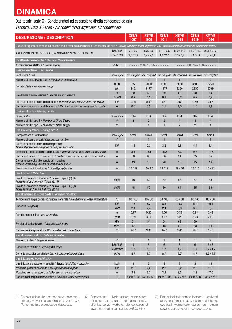
��
Dati tecnici serie X - Condizionatori ad espansione diretta condensati ad ariaTechnical Data X Series - Air cooled direct expansion air conditioners
(1) Resacalcolataalleportateeprevalenzespe-cificate.Prevalenzadisponibileda20a100Paconportateeprestazioniricalcolate.
(2) Rappresenta il ilvello sonoro complessivo,misurato sulla scala A, alla data distanzaall’unità, senza riverbero, alle condizioni dilavoronominaliincampolibero(ISO3744).
(3) Datocalcolatoincampoliberoconiventilatoriallavelocitàmassima.Nelcampoapplicato,eventuali riverberi/attenuazioni del rumoredevonoesseretenutiinconsiderazione.
DESCRIZIONE / DESCRIPTION XST/B1007
XST/B1008
XST/B1011
XST/B1015
XST/B1019
XMT/B1024
XMT/B1028
XMT/B1033
XMT/B1038
XMT/B1049
XMT/B1062
XMT/B2029
XMT/B2038
XMT/B2049
XMT/B2058
XMT/B2069
XMT/B2078
XLT/B2096
XLT/B2125
Capacità frigorifera batteria ad espansione diretta (totale/sensibile) condensata ad aria / Cooling capacity direct expansion coil (total/sensible) for remote air cooled condenser
Aria aspirata �� °C / �0 % u.r. (1) / Return air 24 °C / 50 % u.r. (1)kW / kW �,1/ �,� �,� / �,0 11,1 / �,� 1�,0 / 1�,� 1�,� / 1�,0 ��,� / �1,� ��,� / ��,� ��,� / ��,� ��,� / ��,� ��,1 / ��,1 ��,0 / ��,� �1,� / ��,0 ��,� / ��,1 ��,� / ��,1 ��,� / ��,� ��,0 / ��,0 ��,1 / ��,1 ��,� / ��,1 ��,� / ��,�
TON / TON �,0 / 1,� �,� / �,� �,� / �,� �,� / �,� �,� / �,� �,� / �,1 �,� / �,1 �,� / �,1 �,� / �,� 10,� / �,� 1�,� / 1�,� 1�,� / 1�,� �,1 / �,0 10,� / 10,� 1�,0 / 1�,0 1�,� / 1�,� 1�,� / 1�,� ��,0 / �1,� ��,� / ��,�
Caratteristiche elettriche / Electrical Characteristics
Alimentazione elettrica / Power supply V/Ph/Hz < - - - - ��0 / 1 / �0- - - - - - -> < - - - - - �00 / �+N / �0 - - - - - > < - - - - - - -- - - - - - - - - - - - - - - - - - - - - - - - - - - - - - - - - - - - - - - - - �00 / �+N / �0 - - - - - - -- - - - - - - - - - - - - - - - - - - - - - - - - - - - - - - - - - - - - - - - ->
Sezione ventilante / Fan section
Ventilatore / Fan Tipo / Type dir. coupled dir. coupled dir. coupled dir. coupled dir. coupled dir. coupled dir. coupled dir. coupled dir. coupled dir. coupled dir. coupled dir. coupled dir. coupled dir. coupled dir. coupled dir. coupled dir. coupled dir. coupled dir. coupledNumero di motori/ventilatori / Number of motors/fans n° 1 1 1 1 1 � � � � � � � � � � � � � �
Portata d’aria / Air volume rangem³/h 1��0 �000 �000 ��00 ��00 ���0 ���0 ���0 ��00 ��00 10�00 11��0 ���0 ��00 10�00 11��0 1��00 1��00 1�000cfm �1� 11�� 11�� ���� ���� �0�� �0�� �0�� ���� ���� �001 ��1� �0�� ���� �001 ��1� ���� ���� 10��0
Prevalenza statica residua / Externa static pressurePa �0 �0 �0 �0 �0 �0 �0 �0 �0 �0 �0 �0 �0 �0 �0 �0 �0 �0 �0
In WG 0,� 0,� 0,� 0,� 0,� 0,� 0,� 0,� 0,� 0,� 0,� 0,� 0,� 0,� 0,� 0,� 0,� 0,� 0,�Potenza nominale assorbita motore / Nominal power consumption fan motor kW 0,�� 0,�� 0,�� 0,�� 0,�� 0,�� 0,�� 0,�� 0,�� 0,�� 0,�� 0,�� 0,�� 0,�� 0,�� 0,�� 0,�� 0,�� 0,��Corrente nominale assorbita motore / Nominal current consumption fan motor A 0,� 0,� 1,1 1,� 1,� 1,1 �,� 1,1 1,� 1,� 1,� 1,1 1,� 1,� 1,� 1,� 1,� 1,� 1,�
Sezione filtrante / Filtering section
Filtro / Filter Tipo / Type EU� EU� EU� EU� EU� EU� EU� EU� EU� EU� EU� EU� EU� EU� EU� EU� EU� EU� EU�Numero di filtri tipo T / Number of filters T type n° � � � � � � � � � � � � � � � � � � �Numero di filtri tipo B / Number of filters B type n° 1 1 1 � � � � � � � � � � � � � � � 10
Circuito refrigerante / Cooling circuit
Compressore / Compressor Tipo / Type Scroll Scroll Scroll Scroll Scroll Scroll Scroll Scroll Scroll Scroll Scroll Scroll Scroll Scroll Scroll Scroll Scroll Scroll ScrollNumero di compressori / Compressor number n° 1 1 1 1 1 1 1 1 1 1 1 1 � � � � � � �Potenza nominale assorbita compressoreNominal power consumption of compressor motor kW 1,� �,� �,� �,� �,� �,� �,� �,� �,� 10,� 1�,� 1�,� �,0 �,� �,� �,� �,� 10,0 1�,�
Corrente nominale assorbita compressore / Nominal current input of compressor motor A �,1 1�,1 1�,� �,� �,� 11,� 1�,1 1�,1 1�,0 1�,� ��,0 ��,� �,� �,� 1�,1 1�,� 1�,� 1�,0 ��,�Corrente di spunto a rotore fermo / Locked rotor current of compressor motor A �0 �� �� �1 �� �� 111 111 11� 11� 1�� ��� �1 �� �� 111 11� 11� 1��Corrente assorbita alle condizioni massimeMaximum running current of compressor motor A 1� 1� �0 10 1� 1� �1 �1 �� �� �� �0 10 1� 1� �1 �� �� ��
Dimensioni tubi liquido/gas / Liquid/gas pipe size mm 10 / 1� 10 / 1� 10 / 1� 1� / 1� 1� / 1� 1� / �� 1� / �� 1� / �� 1� / �� 1� / �� �� / �� �� / �� �x1� / �x1� �x1� / �x1� �x1� / �x1� �x1� / �x�� �x1� / �x�� �x1� / �x�� �x�� / �x��
Livelli sonori / Noise level
Livello di pressione sonora a � m in c.l. tipo T (�) (�)Noise level at 2 m in f.f. T type (2) (3) db(A) �� �� �� �� �� �� �� �� �� �� �� �� �� �� �0 �� �� �� ��
Livello di pressione sonora a � m in c.l. tipo B (�) (�)Noise level at 2 m in f.f. B type (2) (3) db(A) �� �0 �0 �� �� �� �� �� �� �� �0 �0 �� �� �� �0 �0 �0 ��
Riscaldamento ad acqua calda / Hot water reheating
Temperatura acqua (ingresso / uscita) nominale / In/out nominal water temperature °C �0 / �0 �0 / �0 �0 / �0 �0 / �0 �0 / �0 �0 / �0 �0 / �0 �0 / �0 �0 / �0 �0 / �0 �0 / �0 �0 / �0 �0 / �0 �0 / �0 �0 / �0 �0 / �0 �0 / �0 �0 / �0 �0 / �0
Capacità / CapacitykW �,� �,� �,� 1�,� 1�,� 1�,� 1�,� 1�,� ��,� ��,� ��,� ��,� 1�,� ��,� ��,� ��,� ��,� ��,� �1,�TON �,1 �,� �,� �,� �,� �,� �,� �,� �,� �,� 10,� 1�,0 �,� �,� 10,� 1�,� 1�,0 1�,0 1�,�
Portata acqua calda / Hot water flowl/s 0,1� 0,�0 0,�0 0,�� 0,�� 0,�� 0,�� 0,�� 0,�� 0,�� 0,�0 1,01 0,�� 0,�� 0,�0 1,01 1,�� 1,�� 1,��
gpm �,�� �,1� �,1� �,�� �,�� �,�� �,�� �,�� �,�� �,�� 1�,�� 1�,01 �,�� �,�� 1�,�� 1�,01 1�,�� 1�,�� ��,��
Perdita di carico totale / Total pressure dropskPa �1 �� �� �� �� �1 �1 �1 �� �� �1 �� �1 �� �1 �� �� �� ��
ft WG 1� 1� 1� �� �� 1� 1� 1� 1� 1� 1� 1� 1� 1� 1� 1� 1� 1� 1�Connessioni acqua calda / Warm water coil connections ”G �/�” �/�” �/�” �/�” �/�” �/�” �/�” �/�” �/�” �/�” 1” 1” �/�” �/�” 1” 1” 1” 1” 1”
Riscaldamento elettrico / electrical heating
Numero di stadi / Stages number n° 1 1 1 1 1 � � � � � � � � � � � � � �
Capacità per stadio / Capacity per stagekW / kW � � � � � � / � � / � � / � � / � � / � � / � � / � � / � � / � � / � � / � 1� / 1� 1� / 1� 1� / 1�TON/TON 1,� 1,� 1,� 1,� 1,� 1,� / 1,� 1,� / 1,� 1,� / 1,� 1,� / �,� 1,� / �,� 1,� / �,� 1,� / �,� 1,� / �,� 1,� / �,� 1,� / �,� 1,� / �,� �,� / �,� �,� / �,� �,� / �,�
Corrente assorbita per stadio / Current consumption per stage A / A �,� �,� �,� �,� �,� �,� / �,� �,� / �,� �,� / �,� �,� / 1�,0 �,� / 1�,0 �,� / 1�,0 �,� / 1�,0 �,� / 1�,0 �,� / 1�,0 �,� / 1�,0 �,� / 1�,0 1�,1 / 1�,1 1�,1 / 1�,1 1�,1 / 1�,1
Umidificazione / humidification
Umidificatore a vapore - capacità / Steam humidifier - capacity kg/h � � � � � 1� 1� 1� 1� 1� 1� 1� 1� 1� 1� 1� 1� 1� 1�Massima potenza assorbita / Max power consumption kW �,� �,� �,� �,� �,� 11,� 11,� 11,� 11,� 11,� 11,� 11,� 11,� 11,� 11,� 11,� 11,� 11,� 11,�
Massima corrente assorbita / Max current consumption A �,� �,� �,� �,� �,� 1�,0 1�,0 1�,0 1�,0 1�,0 1�,0 1�,0 1�,0 1�,0 1�,0 1�,0 1�,0 1�,0 1�,0
Connessioni acqua carico/scarico / Fill/drain water connections ”G �/�”M / �/�” �/�”M / �/�” �/�”M / �/�” �/�”M / �/�” �/�”M / �/�” �/�”M / �/�” �/�”M / �/�” �/�”M / �/�” �/�”M / �/�” �/�”M / �/�” �/�”M / �/�” �/�”M / �/�” �/�”M / �/�” �/�”M / �/�” �/�”M / �/�” �/�”M / �/�” �/�”M / �/�” �/�”M / �/�” �/�”M / �/�”
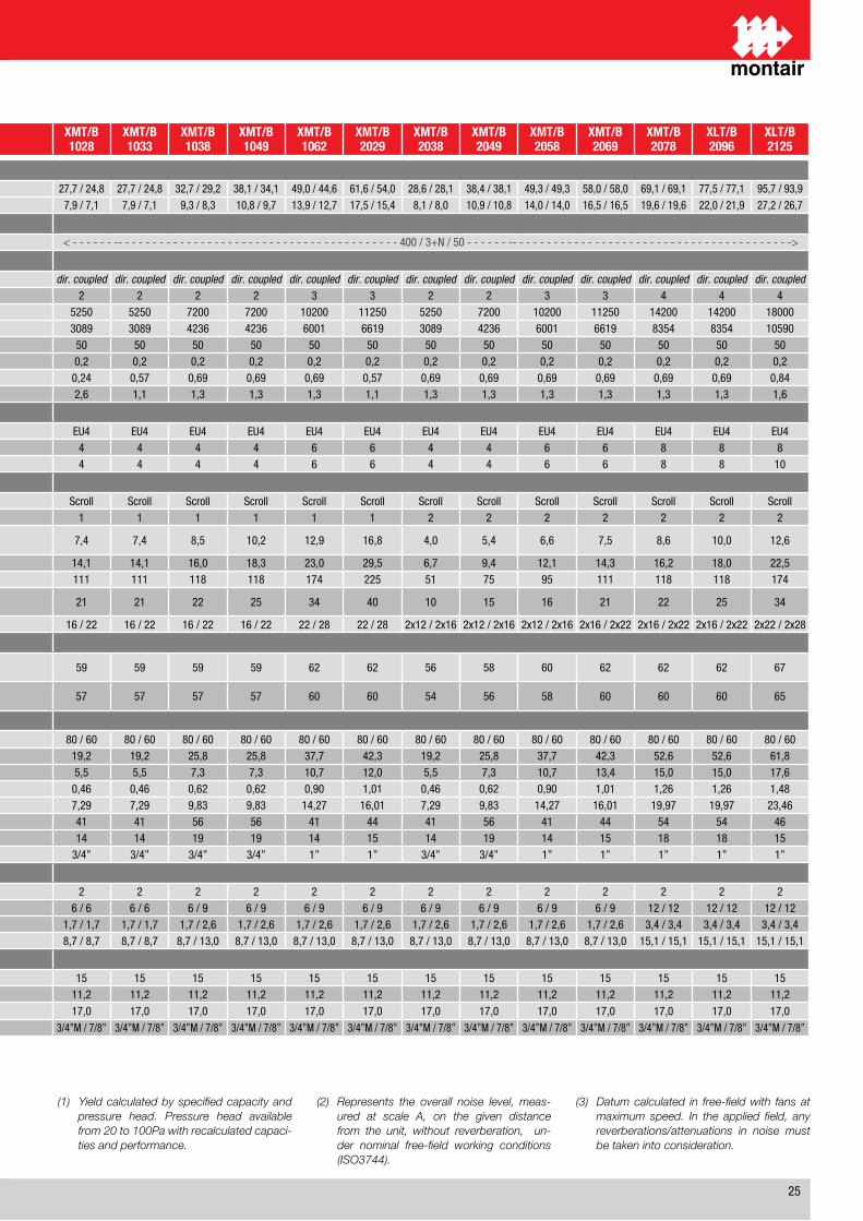
��
Dati tecnici serie X - Condizionatori ad espansione diretta condensati ad ariaTechnical Data X Series - Air cooled direct expansion air conditioners
(1) Yield calculated by specified capacity and pressure head. Pressure head available from 20 to 100Pa with recalculated capaci-ties and performance.
(2) Represents the overall noise level, meas-ured at scale A, on the given distance from the unit, without reverberation, un-der nominal free-field working conditions (ISO3744).
(3) Datum calculated in free-field with fans at maximum speed. In the applied field, any reverberations/attenuations in noise must be taken into consideration.
DESCRIZIONE / DESCRIPTION XST/B1007
XST/B1008
XST/B1011
XST/B1015
XST/B1019
XMT/B1024
XMT/B1028
XMT/B1033
XMT/B1038
XMT/B1049
XMT/B1062
XMT/B2029
XMT/B2038
XMT/B2049
XMT/B2058
XMT/B2069
XMT/B2078
XLT/B2096
XLT/B2125
Capacità frigorifera batteria ad espansione diretta (totale/sensibile) condensata ad aria / Cooling capacity direct expansion coil (total/sensible) for remote air cooled condenser
Aria aspirata �� °C / �0 % u.r. (1) / Return air 24 °C / 50 % u.r. (1)kW / kW �,1/ �,� �,� / �,0 11,1 / �,� 1�,0 / 1�,� 1�,� / 1�,0 ��,� / �1,� ��,� / ��,� ��,� / ��,� ��,� / ��,� ��,1 / ��,1 ��,0 / ��,� �1,� / ��,0 ��,� / ��,1 ��,� / ��,1 ��,� / ��,� ��,0 / ��,0 ��,1 / ��,1 ��,� / ��,1 ��,� / ��,�
TON / TON �,0 / 1,� �,� / �,� �,� / �,� �,� / �,� �,� / �,� �,� / �,1 �,� / �,1 �,� / �,1 �,� / �,� 10,� / �,� 1�,� / 1�,� 1�,� / 1�,� �,1 / �,0 10,� / 10,� 1�,0 / 1�,0 1�,� / 1�,� 1�,� / 1�,� ��,0 / �1,� ��,� / ��,�
Caratteristiche elettriche / Electrical Characteristics
Alimentazione elettrica / Power supply V/Ph/Hz < - - - - ��0 / 1 / �0- - - - - - -> < - - - - - �00 / �+N / �0 - - - - - > < - - - - - - -- - - - - - - - - - - - - - - - - - - - - - - - - - - - - - - - - - - - - - - - - �00 / �+N / �0 - - - - - - -- - - - - - - - - - - - - - - - - - - - - - - - - - - - - - - - - - - - - - - - ->
Sezione ventilante / Fan section
Ventilatore / Fan Tipo / Type dir. coupled dir. coupled dir. coupled dir. coupled dir. coupled dir. coupled dir. coupled dir. coupled dir. coupled dir. coupled dir. coupled dir. coupled dir. coupled dir. coupled dir. coupled dir. coupled dir. coupled dir. coupled dir. coupledNumero di motori/ventilatori / Number of motors/fans n° 1 1 1 1 1 � � � � � � � � � � � � � �
Portata d’aria / Air volume rangem³/h 1��0 �000 �000 ��00 ��00 ���0 ���0 ���0 ��00 ��00 10�00 11��0 ���0 ��00 10�00 11��0 1��00 1��00 1�000cfm �1� 11�� 11�� ���� ���� �0�� �0�� �0�� ���� ���� �001 ��1� �0�� ���� �001 ��1� ���� ���� 10��0
Prevalenza statica residua / Externa static pressurePa �0 �0 �0 �0 �0 �0 �0 �0 �0 �0 �0 �0 �0 �0 �0 �0 �0 �0 �0
In WG 0,� 0,� 0,� 0,� 0,� 0,� 0,� 0,� 0,� 0,� 0,� 0,� 0,� 0,� 0,� 0,� 0,� 0,� 0,�Potenza nominale assorbita motore / Nominal power consumption fan motor kW 0,�� 0,�� 0,�� 0,�� 0,�� 0,�� 0,�� 0,�� 0,�� 0,�� 0,�� 0,�� 0,�� 0,�� 0,�� 0,�� 0,�� 0,�� 0,��Corrente nominale assorbita motore / Nominal current consumption fan motor A 0,� 0,� 1,1 1,� 1,� 1,1 �,� 1,1 1,� 1,� 1,� 1,1 1,� 1,� 1,� 1,� 1,� 1,� 1,�
Sezione filtrante / Filtering section
Filtro / Filter Tipo / Type EU� EU� EU� EU� EU� EU� EU� EU� EU� EU� EU� EU� EU� EU� EU� EU� EU� EU� EU�Numero di filtri tipo T / Number of filters T type n° � � � � � � � � � � � � � � � � � � �Numero di filtri tipo B / Number of filters B type n° 1 1 1 � � � � � � � � � � � � � � � 10
Circuito refrigerante / Cooling circuit
Compressore / Compressor Tipo / Type Scroll Scroll Scroll Scroll Scroll Scroll Scroll Scroll Scroll Scroll Scroll Scroll Scroll Scroll Scroll Scroll Scroll Scroll ScrollNumero di compressori / Compressor number n° 1 1 1 1 1 1 1 1 1 1 1 1 � � � � � � �Potenza nominale assorbita compressoreNominal power consumption of compressor motor kW 1,� �,� �,� �,� �,� �,� �,� �,� �,� 10,� 1�,� 1�,� �,0 �,� �,� �,� �,� 10,0 1�,�
Corrente nominale assorbita compressore / Nominal current input of compressor motor A �,1 1�,1 1�,� �,� �,� 11,� 1�,1 1�,1 1�,0 1�,� ��,0 ��,� �,� �,� 1�,1 1�,� 1�,� 1�,0 ��,�Corrente di spunto a rotore fermo / Locked rotor current of compressor motor A �0 �� �� �1 �� �� 111 111 11� 11� 1�� ��� �1 �� �� 111 11� 11� 1��Corrente assorbita alle condizioni massimeMaximum running current of compressor motor A 1� 1� �0 10 1� 1� �1 �1 �� �� �� �0 10 1� 1� �1 �� �� ��
Dimensioni tubi liquido/gas / Liquid/gas pipe size mm 10 / 1� 10 / 1� 10 / 1� 1� / 1� 1� / 1� 1� / �� 1� / �� 1� / �� 1� / �� 1� / �� �� / �� �� / �� �x1� / �x1� �x1� / �x1� �x1� / �x1� �x1� / �x�� �x1� / �x�� �x1� / �x�� �x�� / �x��
Livelli sonori / Noise level
Livello di pressione sonora a � m in c.l. tipo T (�) (�)Noise level at 2 m in f.f. T type (2) (3) db(A) �� �� �� �� �� �� �� �� �� �� �� �� �� �� �0 �� �� �� ��
Livello di pressione sonora a � m in c.l. tipo B (�) (�)Noise level at 2 m in f.f. B type (2) (3) db(A) �� �0 �0 �� �� �� �� �� �� �� �0 �0 �� �� �� �0 �0 �0 ��
Riscaldamento ad acqua calda / Hot water reheating
Temperatura acqua (ingresso / uscita) nominale / In/out nominal water temperature °C �0 / �0 �0 / �0 �0 / �0 �0 / �0 �0 / �0 �0 / �0 �0 / �0 �0 / �0 �0 / �0 �0 / �0 �0 / �0 �0 / �0 �0 / �0 �0 / �0 �0 / �0 �0 / �0 �0 / �0 �0 / �0 �0 / �0
Capacità / CapacitykW �,� �,� �,� 1�,� 1�,� 1�,� 1�,� 1�,� ��,� ��,� ��,� ��,� 1�,� ��,� ��,� ��,� ��,� ��,� �1,�TON �,1 �,� �,� �,� �,� �,� �,� �,� �,� �,� 10,� 1�,0 �,� �,� 10,� 1�,� 1�,0 1�,0 1�,�
Portata acqua calda / Hot water flowl/s 0,1� 0,�0 0,�0 0,�� 0,�� 0,�� 0,�� 0,�� 0,�� 0,�� 0,�0 1,01 0,�� 0,�� 0,�0 1,01 1,�� 1,�� 1,��
gpm �,�� �,1� �,1� �,�� �,�� �,�� �,�� �,�� �,�� �,�� 1�,�� 1�,01 �,�� �,�� 1�,�� 1�,01 1�,�� 1�,�� ��,��
Perdita di carico totale / Total pressure dropskPa �1 �� �� �� �� �1 �1 �1 �� �� �1 �� �1 �� �1 �� �� �� ��
ft WG 1� 1� 1� �� �� 1� 1� 1� 1� 1� 1� 1� 1� 1� 1� 1� 1� 1� 1�Connessioni acqua calda / Warm water coil connections ”G �/�” �/�” �/�” �/�” �/�” �/�” �/�” �/�” �/�” �/�” 1” 1” �/�” �/�” 1” 1” 1” 1” 1”
Riscaldamento elettrico / electrical heating
Numero di stadi / Stages number n° 1 1 1 1 1 � � � � � � � � � � � � � �
Capacità per stadio / Capacity per stagekW / kW � � � � � � / � � / � � / � � / � � / � � / � � / � � / � � / � � / � � / � 1� / 1� 1� / 1� 1� / 1�TON/TON 1,� 1,� 1,� 1,� 1,� 1,� / 1,� 1,� / 1,� 1,� / 1,� 1,� / �,� 1,� / �,� 1,� / �,� 1,� / �,� 1,� / �,� 1,� / �,� 1,� / �,� 1,� / �,� �,� / �,� �,� / �,� �,� / �,�
Corrente assorbita per stadio / Current consumption per stage A / A �,� �,� �,� �,� �,� �,� / �,� �,� / �,� �,� / �,� �,� / 1�,0 �,� / 1�,0 �,� / 1�,0 �,� / 1�,0 �,� / 1�,0 �,� / 1�,0 �,� / 1�,0 �,� / 1�,0 1�,1 / 1�,1 1�,1 / 1�,1 1�,1 / 1�,1
Umidificazione / humidification
Umidificatore a vapore - capacità / Steam humidifier - capacity kg/h � � � � � 1� 1� 1� 1� 1� 1� 1� 1� 1� 1� 1� 1� 1� 1�Massima potenza assorbita / Max power consumption kW �,� �,� �,� �,� �,� 11,� 11,� 11,� 11,� 11,� 11,� 11,� 11,� 11,� 11,� 11,� 11,� 11,� 11,�
Massima corrente assorbita / Max current consumption A �,� �,� �,� �,� �,� 1�,0 1�,0 1�,0 1�,0 1�,0 1�,0 1�,0 1�,0 1�,0 1�,0 1�,0 1�,0 1�,0 1�,0
Connessioni acqua carico/scarico / Fill/drain water connections ”G �/�”M / �/�” �/�”M / �/�” �/�”M / �/�” �/�”M / �/�” �/�”M / �/�” �/�”M / �/�” �/�”M / �/�” �/�”M / �/�” �/�”M / �/�” �/�”M / �/�” �/�”M / �/�” �/�”M / �/�” �/�”M / �/�” �/�”M / �/�” �/�”M / �/�” �/�”M / �/�” �/�”M / �/�” �/�”M / �/�” �/�”M / �/�”
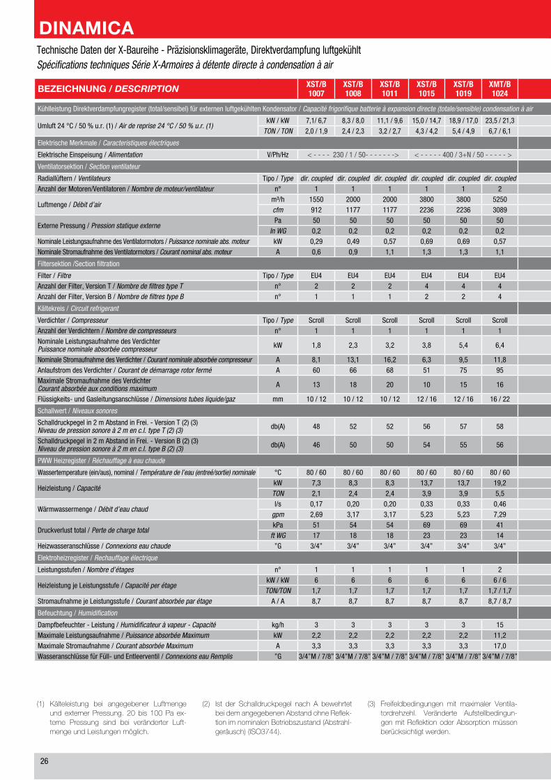
��
(1) Kälteleistung bei angegebener LuftmengeundexternerPressung. 20bis 100Pa ex-terne Pressung sind bei veränderter Luft-mengeundLeistungenmöglich.
(2) Ist der Schalldruckpegel nach A bewehrtetbeidemangegebenenAbstandohneReflek-tionimnominalenBetriebszustand(Abstrahl-geräusch)(ISO3744).
(3) Freifeldbedingungen mit maximaler Ventila-tordrehzehl. Veränderte Aufstellbedingun-genmitReflektionoderAbsorptionmüssenberücksichtigtwerden.
BEZEICHNUNG / DESCRIPTION XST/B1007
XST/B1008
XST/B1011
XST/B1015
XST/B1019
XMT/B1024
XMT/B1028
XMT/B1033
XMT/B1038
XMT/B1049
XMT/B1062
XMT/B2029
XMT/B2038
XMT/B2049
XMT/B2058
XMT/B2069
XMT/B2078
XLT/B2096
XLT/B2125
Kühlleistung Direktverdampfungregister (total/sensibel) für externen luftgekühlten Kondensator / Capacité frigorifique batterie à expansion directe (totale/sensible) condensation à air
Umluft �� °C / �0 % u.r. (1) / Air de reprise 24 °C / 50 % u.r. (1)kW / kW �,1/ �,� �,� / �,0 11,1 / �,� 1�,0 / 1�,� 1�,� / 1�,0 ��,� / �1,� ��,� / ��,� ��,� / ��,� ��,� / ��,� ��,1 / ��,1 ��,0 / ��,� �1,� / ��,0 ��,� / ��,1 ��,� / ��,1 ��,� / ��,� ��,0 / ��,0 ��,1 / ��,1 ��,� / ��,1 ��,� / ��,�
TON / TON �,0 / 1,� �,� / �,� �,� / �,� �,� / �,� �,� / �,� �,� / �,1 �,� / �,1 �,� / �,1 �,� / �,� 10,� / �,� 1�,� / 1�,� 1�,� / 1�,� �,1 / �,0 10,� / 10,� 1�,0 / 1�,0 1�,� / 1�,� 1�,� / 1�,� ��,0 / �1,� ��,� / ��,�
Elektrische Merkmale / Caracteristiques électriques
Elektrische Einspeisung / Alimentation V/Ph/Hz < - - - - ��0 / 1 / �0- - - - - - -> < - - - - - �00 / �+N / �0 - - - - - > < - - - - - - -- - - - - - - - - - - - - - - - - - - - - - - - - - - - - - - - - - - - - - - - - �00 / �+N / �0 - - - - - - -- - - - - - - - - - - - - - - - - - - - - - - - - - - - - - - - - - - - - - - - ->
Ventilatorsektion / Section ventilateur
Radiallüftern / Ventilateurs Tipo / Type dir. coupled dir. coupled dir. coupled dir. coupled dir. coupled dir. coupled dir. coupled dir. coupled dir. coupled dir. coupled dir. coupled dir. coupled dir. coupled dir. coupled dir. coupled dir. coupled dir. coupled dir. coupled dir. coupledAnzahl der Motoren/Ventilatoren / Nombre de moteur/ventilateur n° 1 1 1 1 1 � � � � � � � � � � � � � �
Luftmenge / Débit d’airm³/h 1��0 �000 �000 ��00 ��00 ���0 ���0 ���0 ��00 ��00 10�00 11��0 ���0 ��00 10�00 11��0 1��00 1��00 1�000cfm �1� 11�� 11�� ���� ���� �0�� �0�� �0�� ���� ���� �001 ��1� �0�� ���� �001 ��1� ���� ���� 10��0
Externe Pressung / Pression statique externePa �0 �0 �0 �0 �0 �0 �0 �0 �0 �0 �0 �0 �0 �0 �0 �0 �0 �0 �0
In WG 0,� 0,� 0,� 0,� 0,� 0,� 0,� 0,� 0,� 0,� 0,� 0,� 0,� 0,� 0,� 0,� 0,� 0,� 0,�Nominale Leistungsaufnahme des Ventilatormotors / Puissance nominale abs. moteur kW 0,�� 0,�� 0,�� 0,�� 0,�� 0,�� 0,�� 0,�� 0,�� 0,�� 0,�� 0,�� 0,�� 0,�� 0,�� 0,�� 0,�� 0,�� 0,��Nominale Stromaufnahme des Ventilatormotors / Courant nominal abs. moteur A 0,� 0,� 1,1 1,� 1,� 1,1 �,� 1,1 1,� 1,� 1,� 1,1 1,� 1,� 1,� 1,� 1,� 1,� 1,�
Filtersektion /Section filtration
Filter / Filtre Tipo / Type EU� EU� EU� EU� EU� EU� EU� EU� EU� EU� EU� EU� EU� EU� EU� EU� EU� EU� EU�Anzahl der Filter, Version T / Nombre de filtres type T n° � � � � � � � � � � � � � � � � � � �Anzahl der Filter, Version B / Nombre de filtres type B n° 1 1 1 � � � � � � � � � � � � � � � 10
Kältekreis / Circuit refrigerant
Verdichter / Compresseur Tipo / Type Scroll Scroll Scroll Scroll Scroll Scroll Scroll Scroll Scroll Scroll Scroll Scroll Scroll Scroll Scroll Scroll Scroll Scroll ScrollAnzahl der Verdichtern / Nombre de compresseurs n° 1 1 1 1 1 1 1 1 1 1 1 1 � � � � � � �Nominale Leistungsaufnahme des VerdichterPuissance nominale absorbée compresseur kW 1,� �,� �,� �,� �,� �,� �,� �,� �,� 10,� 1�,� 1�,� �,0 �,� �,� �,� �,� 10,0 1�,�
Nominale Stromaufnahme des Verdichter / Courant nominale absorbée compresseur A �,1 1�,1 1�,� �,� �,� 11,� 1�,1 1�,1 1�,0 1�,� ��,0 ��,� �,� �,� 1�,1 1�,� 1�,� 1�,0 ��,�Anlaufstrom des Verdichter / Courant de démarrage rotor fermé A �0 �� �� �1 �� �� 111 111 11� 11� 1�� ��� �1 �� �� 111 11� 11� 1��Maximale Stromaufnahme des VerdichterCourant absorbée aux conditions maximum A 1� 1� �0 10 1� 1� �1 �1 �� �� �� �0 10 1� 1� �1 �� �� ��
Flüssigkeits- und Gasleitungsanschlüsse / Dimensions tubes liquide/gaz mm 10 / 1� 10 / 1� 10 / 1� 1� / 1� 1� / 1� 1� / �� 1� / �� 1� / �� 1� / �� 1� / �� �� / �� �� / �� �x1� / �x1� �x1� / �x1� �x1� / �x1� �x1� / �x�� �x1� / �x�� �x1� / �x�� �x�� / �x��
Schallwert / Niveaux sonores
Schalldruckpegel in � m Abstand in Frei. - Version T (�) (�)Niveau de pression sonore à 2 m en c.l. type T (2) (3) db(A) �� �� �� �� �� �� �� �� �� �� �� �� �� �� �0 �� �� �� ��
Schalldruckpegel in � m Abstand in Frei. - Version B (�) (�)Niveau de pression sonore à 2 m en c.l. type B (2) (3) db(A) �� �0 �0 �� �� �� �� �� �� �� �0 �0 �� �� �� �0 �0 �0 ��
PWW Heizregister / Réchauffage à eau chaude
Wassertemperature (ein/aus), nominal / Température de l’eau (entreé/sortie) nominale °C �0 / �0 �0 / �0 �0 / �0 �0 / �0 �0 / �0 �0 / �0 �0 / �0 �0 / �0 �0 / �0 �0 / �0 �0 / �0 �0 / �0 �0 / �0 �0 / �0 �0 / �0 �0 / �0 �0 / �0 �0 / �0 �0 / �0
Heizleistung / CapacitékW �,� �,� �,� 1�,� 1�,� 1�,� 1�,� 1�,� ��,� ��,� ��,� ��,� 1�,� ��,� ��,� ��,� ��,� ��,� �1,�TON �,1 �,� �,� �,� �,� �,� �,� �,� �,� �,� 10,� 1�,0 �,� �,� 10,� 1�,� 1�,0 1�,0 1�,�
Wärmwassermenge / Débit d’eau chaudl/s 0,1� 0,�0 0,�0 0,�� 0,�� 0,�� 0,�� 0,�� 0,�� 0,�� 0,�0 1,01 0,�� 0,�� 0,�0 1,01 1,�� 1,�� 1,��
gpm �,�� �,1� �,1� �,�� �,�� �,�� �,�� �,�� �,�� �,�� 1�,�� 1�,01 �,�� �,�� 1�,�� 1�,01 1�,�� 1�,�� ��,��
Druckverlust total / Perte de charge totalkPa �1 �� �� �� �� �1 �1 �1 �� �� �1 �� �1 �� �1 �� �� �� ��
ft WG 1� 1� 1� �� �� 1� 1� 1� 1� 1� 1� 1� 1� 1� 1� 1� 1� 1� 1�Heizwasseranschlüsse / Connexions eau chaude ”G �/�” �/�” �/�” �/�” �/�” �/�” �/�” �/�” �/�” �/�” 1” 1” �/�” �/�” 1” 1” 1” 1” 1”
Elektroheizregister / Rechauffage électrique
Leistungsstufen / Nombre d’étages n° 1 1 1 1 1 � � � � � � � � � � � � � �
Heizleistung je Leistungsstufe / Capacité per étagekW / kW � � � � � � / � � / � � / � � / � � / � � / � � / � � / � � / � � / � � / � 1� / 1� 1� / 1� 1� / 1�TON/TON 1,� 1,� 1,� 1,� 1,� 1,� / 1,� 1,� / 1,� 1,� / 1,� 1,� / �,� 1,� / �,� 1,� / �,� 1,� / �,� 1,� / �,� 1,� / �,� 1,� / �,� 1,� / �,� �,� / �,� �,� / �,� �,� / �,�
Stromaufnahme je Leistungsstufe / Courant absorbée par étage A / A �,� �,� �,� �,� �,� �,� / �,� �,� / �,� �,� / �,� �,� / 1�,0 �,� / 1�,0 �,� / 1�,0 �,� / 1�,0 �,� / 1�,0 �,� / 1�,0 �,� / 1�,0 �,� / 1�,0 1�,1 / 1�,1 1�,1 / 1�,1 1�,1 / 1�,1
Befeuchtung / Humidification
Dampfbefeuchter - Leistung / Humidificateur à vapeur - Capacité kg/h � � � � � 1� 1� 1� 1� 1� 1� 1� 1� 1� 1� 1� 1� 1� 1�Maximale Leistungsaufnahme / Puissance absorbée Maximum kW �,� �,� �,� �,� �,� 11,� 11,� 11,� 11,� 11,� 11,� 11,� 11,� 11,� 11,� 11,� 11,� 11,� 11,�Maximale Stromaufnahme / Courant absorbée Maximum A �,� �,� �,� �,� �,� 1�,0 1�,0 1�,0 1�,0 1�,0 1�,0 1�,0 1�,0 1�,0 1�,0 1�,0 1�,0 1�,0 1�,0Wasseranschlüsse für Füll- und Entleerventil / Connexions eau Remplis ”G �/�”M / �/�” �/�”M / �/�” �/�”M / �/�” �/�”M / �/�” �/�”M / �/�” �/�”M / �/�” �/�”M / �/�” �/�”M / �/�” �/�”M / �/�” �/�”M / �/�” �/�”M / �/�” �/�”M / �/�” �/�”M / �/�” �/�”M / �/�” �/�”M / �/�” �/�”M / �/�” �/�”M / �/�” �/�”M / �/�” �/�”M / �/�”
Technische Daten der X-Baureihe - Präzisionsklimageräte, Direktverdampfung luftgekühltSpécifications techniques Série X-Armoires à détente directe à condensation à air
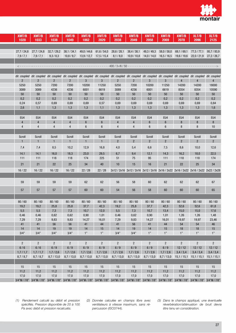
��
(1) Rendement calculé au débit et pression spécifiés. Pression disponible de 20 à 100 Pa avec debit et pression recalculés.
(2) Donnée calculée en champs libre avec ventilateurs à vitesse maximum, sans ré-percussion (ISO3744).
(3) Dans le champs appliqué, une éventuelle réverbération/atténuation de bruit devra être tenu en considération.
BEZEICHNUNG / DESCRIPTION XST/B1007
XST/B1008
XST/B1011
XST/B1015
XST/B1019
XMT/B1024
XMT/B1028
XMT/B1033
XMT/B1038
XMT/B1049
XMT/B1062
XMT/B2029
XMT/B2038
XMT/B2049
XMT/B2058
XMT/B2069
XMT/B2078
XLT/B2096
XLT/B2125
Kühlleistung Direktverdampfungregister (total/sensibel) für externen luftgekühlten Kondensator / Capacité frigorifique batterie à expansion directe (totale/sensible) condensation à air
Umluft �� °C / �0 % u.r. (1) / Air de reprise 24 °C / 50 % u.r. (1)kW / kW �,1/ �,� �,� / �,0 11,1 / �,� 1�,0 / 1�,� 1�,� / 1�,0 ��,� / �1,� ��,� / ��,� ��,� / ��,� ��,� / ��,� ��,1 / ��,1 ��,0 / ��,� �1,� / ��,0 ��,� / ��,1 ��,� / ��,1 ��,� / ��,� ��,0 / ��,0 ��,1 / ��,1 ��,� / ��,1 ��,� / ��,�
TON / TON �,0 / 1,� �,� / �,� �,� / �,� �,� / �,� �,� / �,� �,� / �,1 �,� / �,1 �,� / �,1 �,� / �,� 10,� / �,� 1�,� / 1�,� 1�,� / 1�,� �,1 / �,0 10,� / 10,� 1�,0 / 1�,0 1�,� / 1�,� 1�,� / 1�,� ��,0 / �1,� ��,� / ��,�
Elektrische Merkmale / Caracteristiques électriques
Elektrische Einspeisung / Alimentation V/Ph/Hz < - - - - ��0 / 1 / �0- - - - - - -> < - - - - - �00 / �+N / �0 - - - - - > < - - - - - - -- - - - - - - - - - - - - - - - - - - - - - - - - - - - - - - - - - - - - - - - - �00 / �+N / �0 - - - - - - -- - - - - - - - - - - - - - - - - - - - - - - - - - - - - - - - - - - - - - - - ->
Ventilatorsektion / Section ventilateur
Radiallüftern / Ventilateurs Tipo / Type dir. coupled dir. coupled dir. coupled dir. coupled dir. coupled dir. coupled dir. coupled dir. coupled dir. coupled dir. coupled dir. coupled dir. coupled dir. coupled dir. coupled dir. coupled dir. coupled dir. coupled dir. coupled dir. coupledAnzahl der Motoren/Ventilatoren / Nombre de moteur/ventilateur n° 1 1 1 1 1 � � � � � � � � � � � � � �
Luftmenge / Débit d’airm³/h 1��0 �000 �000 ��00 ��00 ���0 ���0 ���0 ��00 ��00 10�00 11��0 ���0 ��00 10�00 11��0 1��00 1��00 1�000cfm �1� 11�� 11�� ���� ���� �0�� �0�� �0�� ���� ���� �001 ��1� �0�� ���� �001 ��1� ���� ���� 10��0
Externe Pressung / Pression statique externePa �0 �0 �0 �0 �0 �0 �0 �0 �0 �0 �0 �0 �0 �0 �0 �0 �0 �0 �0
In WG 0,� 0,� 0,� 0,� 0,� 0,� 0,� 0,� 0,� 0,� 0,� 0,� 0,� 0,� 0,� 0,� 0,� 0,� 0,�Nominale Leistungsaufnahme des Ventilatormotors / Puissance nominale abs. moteur kW 0,�� 0,�� 0,�� 0,�� 0,�� 0,�� 0,�� 0,�� 0,�� 0,�� 0,�� 0,�� 0,�� 0,�� 0,�� 0,�� 0,�� 0,�� 0,��Nominale Stromaufnahme des Ventilatormotors / Courant nominal abs. moteur A 0,� 0,� 1,1 1,� 1,� 1,1 �,� 1,1 1,� 1,� 1,� 1,1 1,� 1,� 1,� 1,� 1,� 1,� 1,�
Filtersektion /Section filtration
Filter / Filtre Tipo / Type EU� EU� EU� EU� EU� EU� EU� EU� EU� EU� EU� EU� EU� EU� EU� EU� EU� EU� EU�Anzahl der Filter, Version T / Nombre de filtres type T n° � � � � � � � � � � � � � � � � � � �Anzahl der Filter, Version B / Nombre de filtres type B n° 1 1 1 � � � � � � � � � � � � � � � 10
Kältekreis / Circuit refrigerant
Verdichter / Compresseur Tipo / Type Scroll Scroll Scroll Scroll Scroll Scroll Scroll Scroll Scroll Scroll Scroll Scroll Scroll Scroll Scroll Scroll Scroll Scroll ScrollAnzahl der Verdichtern / Nombre de compresseurs n° 1 1 1 1 1 1 1 1 1 1 1 1 � � � � � � �Nominale Leistungsaufnahme des VerdichterPuissance nominale absorbée compresseur kW 1,� �,� �,� �,� �,� �,� �,� �,� �,� 10,� 1�,� 1�,� �,0 �,� �,� �,� �,� 10,0 1�,�
Nominale Stromaufnahme des Verdichter / Courant nominale absorbée compresseur A �,1 1�,1 1�,� �,� �,� 11,� 1�,1 1�,1 1�,0 1�,� ��,0 ��,� �,� �,� 1�,1 1�,� 1�,� 1�,0 ��,�Anlaufstrom des Verdichter / Courant de démarrage rotor fermé A �0 �� �� �1 �� �� 111 111 11� 11� 1�� ��� �1 �� �� 111 11� 11� 1��Maximale Stromaufnahme des VerdichterCourant absorbée aux conditions maximum A 1� 1� �0 10 1� 1� �1 �1 �� �� �� �0 10 1� 1� �1 �� �� ��
Flüssigkeits- und Gasleitungsanschlüsse / Dimensions tubes liquide/gaz mm 10 / 1� 10 / 1� 10 / 1� 1� / 1� 1� / 1� 1� / �� 1� / �� 1� / �� 1� / �� 1� / �� �� / �� �� / �� �x1� / �x1� �x1� / �x1� �x1� / �x1� �x1� / �x�� �x1� / �x�� �x1� / �x�� �x�� / �x��
Schallwert / Niveaux sonores
Schalldruckpegel in � m Abstand in Frei. - Version T (�) (�)Niveau de pression sonore à 2 m en c.l. type T (2) (3) db(A) �� �� �� �� �� �� �� �� �� �� �� �� �� �� �0 �� �� �� ��
Schalldruckpegel in � m Abstand in Frei. - Version B (�) (�)Niveau de pression sonore à 2 m en c.l. type B (2) (3) db(A) �� �0 �0 �� �� �� �� �� �� �� �0 �0 �� �� �� �0 �0 �0 ��
PWW Heizregister / Réchauffage à eau chaude
Wassertemperature (ein/aus), nominal / Température de l’eau (entreé/sortie) nominale °C �0 / �0 �0 / �0 �0 / �0 �0 / �0 �0 / �0 �0 / �0 �0 / �0 �0 / �0 �0 / �0 �0 / �0 �0 / �0 �0 / �0 �0 / �0 �0 / �0 �0 / �0 �0 / �0 �0 / �0 �0 / �0 �0 / �0
Heizleistung / CapacitékW �,� �,� �,� 1�,� 1�,� 1�,� 1�,� 1�,� ��,� ��,� ��,� ��,� 1�,� ��,� ��,� ��,� ��,� ��,� �1,�TON �,1 �,� �,� �,� �,� �,� �,� �,� �,� �,� 10,� 1�,0 �,� �,� 10,� 1�,� 1�,0 1�,0 1�,�
Wärmwassermenge / Débit d’eau chaudl/s 0,1� 0,�0 0,�0 0,�� 0,�� 0,�� 0,�� 0,�� 0,�� 0,�� 0,�0 1,01 0,�� 0,�� 0,�0 1,01 1,�� 1,�� 1,��
gpm �,�� �,1� �,1� �,�� �,�� �,�� �,�� �,�� �,�� �,�� 1�,�� 1�,01 �,�� �,�� 1�,�� 1�,01 1�,�� 1�,�� ��,��
Druckverlust total / Perte de charge totalkPa �1 �� �� �� �� �1 �1 �1 �� �� �1 �� �1 �� �1 �� �� �� ��
ft WG 1� 1� 1� �� �� 1� 1� 1� 1� 1� 1� 1� 1� 1� 1� 1� 1� 1� 1�Heizwasseranschlüsse / Connexions eau chaude ”G �/�” �/�” �/�” �/�” �/�” �/�” �/�” �/�” �/�” �/�” 1” 1” �/�” �/�” 1” 1” 1” 1” 1”
Elektroheizregister / Rechauffage électrique
Leistungsstufen / Nombre d’étages n° 1 1 1 1 1 � � � � � � � � � � � � � �
Heizleistung je Leistungsstufe / Capacité per étagekW / kW � � � � � � / � � / � � / � � / � � / � � / � � / � � / � � / � � / � � / � 1� / 1� 1� / 1� 1� / 1�TON/TON 1,� 1,� 1,� 1,� 1,� 1,� / 1,� 1,� / 1,� 1,� / 1,� 1,� / �,� 1,� / �,� 1,� / �,� 1,� / �,� 1,� / �,� 1,� / �,� 1,� / �,� 1,� / �,� �,� / �,� �,� / �,� �,� / �,�
Stromaufnahme je Leistungsstufe / Courant absorbée par étage A / A �,� �,� �,� �,� �,� �,� / �,� �,� / �,� �,� / �,� �,� / 1�,0 �,� / 1�,0 �,� / 1�,0 �,� / 1�,0 �,� / 1�,0 �,� / 1�,0 �,� / 1�,0 �,� / 1�,0 1�,1 / 1�,1 1�,1 / 1�,1 1�,1 / 1�,1
Befeuchtung / Humidification
Dampfbefeuchter - Leistung / Humidificateur à vapeur - Capacité kg/h � � � � � 1� 1� 1� 1� 1� 1� 1� 1� 1� 1� 1� 1� 1� 1�Maximale Leistungsaufnahme / Puissance absorbée Maximum kW �,� �,� �,� �,� �,� 11,� 11,� 11,� 11,� 11,� 11,� 11,� 11,� 11,� 11,� 11,� 11,� 11,� 11,�Maximale Stromaufnahme / Courant absorbée Maximum A �,� �,� �,� �,� �,� 1�,0 1�,0 1�,0 1�,0 1�,0 1�,0 1�,0 1�,0 1�,0 1�,0 1�,0 1�,0 1�,0 1�,0Wasseranschlüsse für Füll- und Entleerventil / Connexions eau Remplis ”G �/�”M / �/�” �/�”M / �/�” �/�”M / �/�” �/�”M / �/�” �/�”M / �/�” �/�”M / �/�” �/�”M / �/�” �/�”M / �/�” �/�”M / �/�” �/�”M / �/�” �/�”M / �/�” �/�”M / �/�” �/�”M / �/�” �/�”M / �/�” �/�”M / �/�” �/�”M / �/�” �/�”M / �/�” �/�”M / �/�” �/�”M / �/�”
Technische Daten der X-Baureihe - Präzisionsklimageräte, Direktverdampfung luftgekühltSpécifications techniques Série X-Armoires à détente directe à condensation à air
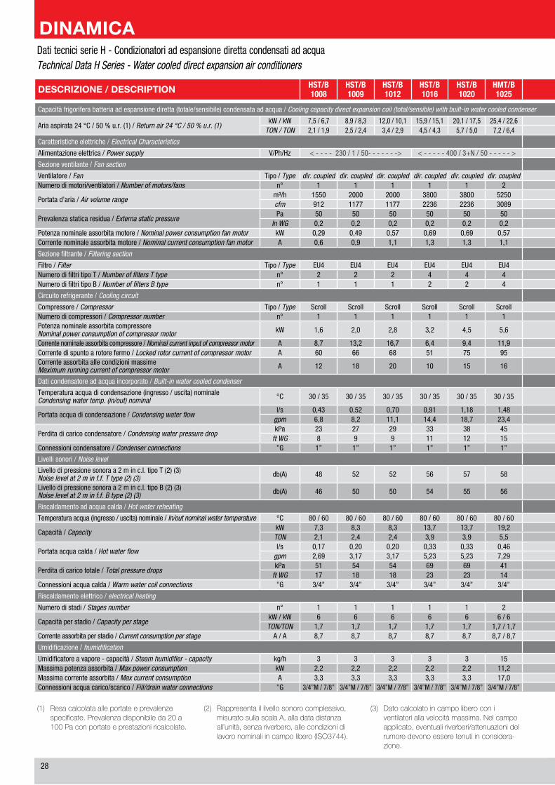
��
DESCRIZIONE / DESCRIPTION HST/B1008
HST/B1009
HST/B1012
HST/B1016
HST/B1020
HMT/B1025
HMT/B1030
HMT/B1036
HMT/B1041
HMT/B1053
HMT/B1066
HMT/B2031
HMT/B2041
HMT/B2055
HMT/B2064
HMT/B2074
HMT/B2083
HLT/B2104
HLT/B2134
Capacità frigorifera batteria ad espansione diretta (totale/sensibile) condensata ad acqua / Cooling capacity direct expansion coil (total/sensible) with built-in water cooled condenser
Aria aspirata �� °C / �0 % u.r. (1) / Return air 24 °C / 50 % u.r. (1)kW / kW �,� / �,� �,� / �,� 1�,0 / 10,1 1�,� / 1�,1 �0,1 / 1�,� ��,� / ��,� �0,� / ��,1 ��,� / �0,� �0,� / ��,� ��,� / ��,1 ��,1 / ��,� �1,� / �0,� �1,� / �1,1 ��,� / ��,0 ��,� / ��,� ��,�/ ��,0 ��,� / ��,� 10�,0 / 10�,0 1��,� / 1��,�
TON / TON �,1 / 1,� �,� / �,� �,� / �,� �,� / �,� �,� / �,0 �,� / �,� �,� / �,� 10,1 / �,� 11,� / 10,1 1�,0 / 1�,1 1�,� / 1�,1 �,� / �,� 11,� / 11,� 1�,� / 1�,� 1�,� / 1�,0 �1,0 / �1,0 ��,� / ��,� ��,� / ��,� ��,0 / ��,0
Caratteristiche elettriche / Electrical Characteristics
Alimentazione elettrica / Power supply V/Ph/Hz < - - - - ��0 / 1 / �0- - - - - - -> < - - - - - �00 / �+N / �0 - - - - - > < - - - - - - -- - - - - - - - - - - - - - - - - - - - - - - - - - - - - - - - - - - - - - - - - �00 / �+N / �0 - - - - - - -- - - - - - - - - - - - - - - - - - - - - - - - - - - - - - - - - - - - - - - - ->
Sezione ventilante / Fan section
Ventilatore / Fan Tipo / Type dir. coupled dir. coupled dir. coupled dir. coupled dir. coupled dir. coupled dir. coupled dir. coupled dir. coupled dir. coupled dir. coupled dir. coupled dir. coupled dir. coupled dir. coupled dir. coupled dir. coupled dir. coupled dir. coupledNumero di motori/ventilatori / Number of motors/fans n° 1 1 1 1 1 � � � � � � � � � � � � � �
Portata d’aria / Air volume rangem³/h 1��0 �000 �000 ��00 ��00 ���0 ���0 ��00 ��00 10�00 11��0 ���0 ��00 10�00 11��0 1��00 1��00 1�000 ��000cfm �1� 11�� 11�� ���� ���� �0�� �0�� ���� ���� �001 ��1� �0�� ���� �001 ��1� ���� ���� 10��0 1�1�0
Prevalenza statica residua / Externa static pressurePa �0 �0 �0 �0 �0 �0 �0 �0 �0 �0 �0 �0 �0 �0 �0 �0 �0 �0 �0
In WG 0,� 0,� 0,� 0,� 0,� 0,� 0,� 0,� 0,� 0,� 0,� 0,� 0,� 0,� 0,� 0,� 0,� 0,� 0,�Potenza nominale assorbita motore / Nominal power consumption fan motor kW 0,�� 0,�� 0,�� 0,�� 0,�� 0,�� 0,�� 0,�� 0,�� 0,�� 0,�� 0,�� 0,�� 0,�� 0,�� 0,�� 0,�� 0,�� 0,��Corrente nominale assorbita motore / Nominal current consumption fan motor A 0,� 0,� 1,1 1,� 1,� 1,1 1,1 1,� 1,� 1,� 1,� 1,1 1,� 1,� 1,� 1,� 1,� 1,� 1,�
Sezione filtrante / Filtering section
Filtro / Filter Tipo / Type EU� EU� EU� EU� EU� EU� EU� EU� EU� EU� EU� EU� EU� EU� EU� EU� EU� EU� EU�Numero di filtri tipo T / Number of filters T type n° � � � � � � � � � � � � � � � � � � 10Numero di filtri tipo B / Number of filters B type n° 1 1 1 � � � � � � � � � � � � � � 10 10
Circuito refrigerante / Cooling circuit
Compressore / Compressor Tipo / Type Scroll Scroll Scroll Scroll Scroll Scroll Scroll Scroll Scroll Scroll Scroll Scroll Scroll Scroll Scroll Scroll Scroll Scroll ScrollNumero di compressori / Compressor number n° 1 1 1 1 1 1 1 1 1 1 1 � � � � � � � �Potenza nominale assorbita compressoreNominal power consumption of compressor motor kW 1,� �,0 �,� �,� �,� �,� �,� �,� �,� 11,� 1�,� �,� �,� �,� �,� �,� �,� 11,� 1�,�
Corrente nominale assorbita compressore / Nominal current input of compressor motor A �,� 1�,� 1�,� �,� �,� 11,� 1�,1 1�,0 1�,� ��,1 ��,� �,� �,� 1�,� 1�,� 1�,� 1�,0 ��,� ��,�Corrente di spunto a rotore fermo / Locked rotor current of compressor motor A �0 �� �� �1 �� �� 111 11� 11� 1�� ��� �1 �� �� 111 11� 11� 1�� ���Corrente assorbita alle condizioni massimeMaximum running current of compressor motor A 1� 1� �0 10 1� 1� �1 �� �� �� �0 10 1� 1� �1 �� �� �� �0
Dati condensatore ad acqua incorporato / Built-in water cooled condenser
Temperatura acqua di condensazione (ingresso / uscita) nominaleCondensing water temp. (in/out) nominal °C �0 / �� �0 / �� �0 / �� �0 / �� �0 / �� �0 / �� �0 / �� �0 / �� �0 / �� �0 / �� �0 / �� �0 / �� �0 / �� �0 / �� �0 / �� �0 / �� �0 / �� �0 / �� �0 / ��
Portata acqua di condensazione / Condensing water flowl/s 0,�� 0,�� 0,�0 0,�1 1,1� 1,�� 1,�� �,0� �,�� �,0� �,�� 1,�� �,1� �,�� �,�� �,�� �,�� �,�0 �,0�
gpm �,� �,� 11,1 1�,� 1�,� ��,� ��,� ��,� ��,� ��,� �1,1 ��,1 ��,� ��,� ��,� �1,� ��,1 ��,1 11�,�
Perdita di carico condensatore / Condensing water pressure dropkPa �� �� �� �� �� �� �� �� �� �� �� �1 �0 �� �� �� �� �1 ��
ft WG � � � 11 1� 1� 11 1� 1� 1� 1� 10 1� 1� 1� 1� 1� 1� 1�Connessioni condensatore / Condenser connections ”G 1” 1” 1” 1” 1” 1” 1” 1” 1” 1” 1”1/� � x 1” � x 1” � x 1” � x 1” � x 1” � x 1” � x 1” � x 1”1/�
Livelli sonori / Noise level
Livello di pressione sonora a � m in c.l. tipo T (�) (�)Noise level at 2 m in f.f. T type (2) (3) db(A) �� �� �� �� �� �� �� �� �� �� �� �� �� �0 �� �� �� �� �0
Livello di pressione sonora a � m in c.l. tipo B (�) (�)Noise level at 2 m in f.f. B type (2) (3) db(A) �� �0 �0 �� �� �� �� �� �� �0 �0 �� �� �� �0 �0 �0 �� ��
Riscaldamento ad acqua calda / Hot water reheating
Temperatura acqua (ingresso / uscita) nominale / In/out nominal water temperature °C �0 / �0 �0 / �0 �0 / �0 �0 / �0 �0 / �0 �0 / �0 �0 / �0 �0 / �0 �0 / �0 �0 / �0 �0 / �0 �0 / �0 �0 / �0 �0 / �0 �0 / �0 �0 / �0 �0 / �0 �0 / �0 �0 / �0
Capacità / CapacitykW �,� �,� �,� 1�,� 1�,� 1�,� 1�,� ��,� ��,� ��,� ��,� 1�,� ��,� ��,� ��,� ��,� ��,� �1,� ��,�TON �,1 �,� �,� �,� �,� �,� �,� �,� �,� 10,� 1�,0 �,� �,� 10,� 1�,� 1�,0 1�,0 1�,� ��,�
Portata acqua calda / Hot water flowl/s 0,1� 0,�0 0,�0 0,�� 0,�� 0,�� 0,�� 0,�� 0,�� 0,�0 1,01 0,�� 0,�� 0,�0 1,01 1,�� 1,�� 1,�� 1,��
gpm �,�� �,1� �,1� �,�� �,�� �,�� �,�� �,�� �,�� 1�,�� 1�,01 �,�� �,�� 1�,�� 1�,01 1�,�� 1�,�� ��,�� ��,�0
Perdita di carico totale / Total pressure dropskPa �1 �� �� �� �� �1 �1 �� �� �1 �� �1 �� �1 �� �� �� �� ��
ft WG 1� 1� 1� �� �� 1� 1� 1� 1� 1� 1� 1� 1� 1� 1� 1� 1� 1� �1Connessioni acqua calda / Warm water coil connections ”G �/�” �/�” �/�” �/�” �/�” �/�” �/�” �/�” �/�” 1” 1” �/�” �/�” 1” 1” 1” 1” 1” 1”1/�
Riscaldamento elettrico / electrical heating
Numero di stadi / Stages number n° 1 1 1 1 1 � � � � � � � � � � � � � �
Capacità per stadio / Capacity per stagekW / kW � � � � � � / � � / � � / � � / � � / � � / � � / � � / � � / � � / � 1� / 1� 1� / 1� 1� / 1� 1� / 1�TON/TON 1,� 1,� 1,� 1,� 1,� 1,� / 1,� 1,� / 1,� 1,� / �,� 1,� / �,� 1,� / �,� 1,� / �,� 1,� / �,� 1,� / �,� 1,� / �,� 1,� / �,� �,� / �,� �,� / �,� �,� / �,� �,� / �,�
Corrente assorbita per stadio / Current consumption per stage A / A �,� �,� �,� �,� �,� �,� / �,� �,� / �,� �,� / 1�,0 �,� / 1�,0 �,� / 1�,0 �,� / 1�,0 �,� / 1�,0 �,� / 1�,0 �,� / 1�,0 �,� / 1�,0 1�,1 / 1�,1 1�,1 / 1�,1 1�,1 / 1�,1 1�,1 / 1�,1
Umidificazione / humidification
Umidificatore a vapore - capacità / Steam humidifier - capacity kg/h � � � � � 1� 1� 1� 1� 1� 1� 1� 1� 1� 1� 1� 1� 1� 1�Massima potenza assorbita / Max power consumption kW �,� �,� �,� �,� �,� 11,� 11,� 11,� 11,� 11,� 11,� 11,� 11,� 11,� 11,� 11,� 11,� 11,� 11,�Massima corrente assorbita / Max current consumption A �,� �,� �,� �,� �,� 1�,0 1�,0 1�,0 1�,0 1�,0 1�,0 1�,0 1�,0 1�,0 1�,0 1�,0 1�,0 1�,0 1�,0Connessioni acqua carico/scarico / Fill/drain water connections ”G �/�”M / �/�” �/�”M / �/�” �/�”M / �/�” �/�”M / �/�” �/�”M / �/�” �/�”M / �/�” �/�”M / �/�” �/�”M / �/�” �/�”M / �/�” �/�”M / �/�” �/�”M / �/�” �/�”M / �/�” �/�”M / �/�” �/�”M / �/�” �/�”M / �/�” �/�”M / �/�” �/�”M / �/�” �/�”M / �/�” �/�”M / �/�”
(1) Resacalcolataalleportateeprevalenze specificate.Prevalenzadisponibileda20a 100Paconportateeprestazioniricalcolate.
(2) Rappresentaililvellosonorocomplessivo,misuratosullascalaA,alladatadistanzaall’unità,senzariverbero,allecondizionidilavoronominaliincampolibero(ISO3744).
(3) Datocalcolatoincampoliberoconiventilatoriallavelocitàmassima.Nelcampoapplicato,eventualiriverberi/attenuazionidelrumoredevonoesseretenutiinconsidera-zione.
Dati tecnici serie H - Condizionatori ad espansione diretta condensati ad acqua Technical Data H Series - Water cooled direct expansion air conditioners
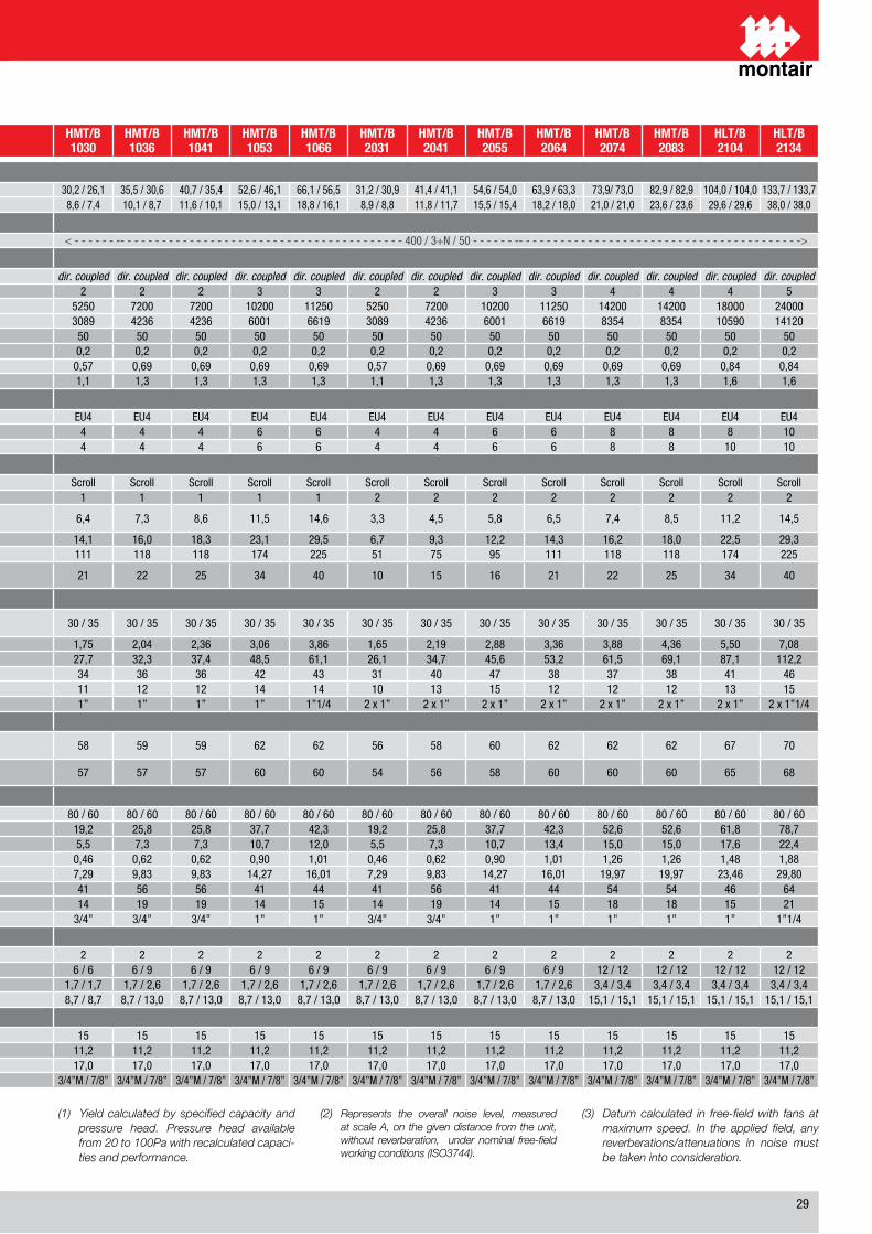
��
DESCRIZIONE / DESCRIPTION HST/B1008
HST/B1009
HST/B1012
HST/B1016
HST/B1020
HMT/B1025
HMT/B1030
HMT/B1036
HMT/B1041
HMT/B1053
HMT/B1066
HMT/B2031
HMT/B2041
HMT/B2055
HMT/B2064
HMT/B2074
HMT/B2083
HLT/B2104
HLT/B2134
Capacità frigorifera batteria ad espansione diretta (totale/sensibile) condensata ad acqua / Cooling capacity direct expansion coil (total/sensible) with built-in water cooled condenser
Aria aspirata �� °C / �0 % u.r. (1) / Return air 24 °C / 50 % u.r. (1)kW / kW �,� / �,� �,� / �,� 1�,0 / 10,1 1�,� / 1�,1 �0,1 / 1�,� ��,� / ��,� �0,� / ��,1 ��,� / �0,� �0,� / ��,� ��,� / ��,1 ��,1 / ��,� �1,� / �0,� �1,� / �1,1 ��,� / ��,0 ��,� / ��,� ��,�/ ��,0 ��,� / ��,� 10�,0 / 10�,0 1��,� / 1��,�
TON / TON �,1 / 1,� �,� / �,� �,� / �,� �,� / �,� �,� / �,0 �,� / �,� �,� / �,� 10,1 / �,� 11,� / 10,1 1�,0 / 1�,1 1�,� / 1�,1 �,� / �,� 11,� / 11,� 1�,� / 1�,� 1�,� / 1�,0 �1,0 / �1,0 ��,� / ��,� ��,� / ��,� ��,0 / ��,0
Caratteristiche elettriche / Electrical Characteristics
Alimentazione elettrica / Power supply V/Ph/Hz < - - - - ��0 / 1 / �0- - - - - - -> < - - - - - �00 / �+N / �0 - - - - - > < - - - - - - -- - - - - - - - - - - - - - - - - - - - - - - - - - - - - - - - - - - - - - - - - �00 / �+N / �0 - - - - - - -- - - - - - - - - - - - - - - - - - - - - - - - - - - - - - - - - - - - - - - - ->
Sezione ventilante / Fan section
Ventilatore / Fan Tipo / Type dir. coupled dir. coupled dir. coupled dir. coupled dir. coupled dir. coupled dir. coupled dir. coupled dir. coupled dir. coupled dir. coupled dir. coupled dir. coupled dir. coupled dir. coupled dir. coupled dir. coupled dir. coupled dir. coupledNumero di motori/ventilatori / Number of motors/fans n° 1 1 1 1 1 � � � � � � � � � � � � � �
Portata d’aria / Air volume rangem³/h 1��0 �000 �000 ��00 ��00 ���0 ���0 ��00 ��00 10�00 11��0 ���0 ��00 10�00 11��0 1��00 1��00 1�000 ��000cfm �1� 11�� 11�� ���� ���� �0�� �0�� ���� ���� �001 ��1� �0�� ���� �001 ��1� ���� ���� 10��0 1�1�0
Prevalenza statica residua / Externa static pressurePa �0 �0 �0 �0 �0 �0 �0 �0 �0 �0 �0 �0 �0 �0 �0 �0 �0 �0 �0
In WG 0,� 0,� 0,� 0,� 0,� 0,� 0,� 0,� 0,� 0,� 0,� 0,� 0,� 0,� 0,� 0,� 0,� 0,� 0,�Potenza nominale assorbita motore / Nominal power consumption fan motor kW 0,�� 0,�� 0,�� 0,�� 0,�� 0,�� 0,�� 0,�� 0,�� 0,�� 0,�� 0,�� 0,�� 0,�� 0,�� 0,�� 0,�� 0,�� 0,��Corrente nominale assorbita motore / Nominal current consumption fan motor A 0,� 0,� 1,1 1,� 1,� 1,1 1,1 1,� 1,� 1,� 1,� 1,1 1,� 1,� 1,� 1,� 1,� 1,� 1,�
Sezione filtrante / Filtering section
Filtro / Filter Tipo / Type EU� EU� EU� EU� EU� EU� EU� EU� EU� EU� EU� EU� EU� EU� EU� EU� EU� EU� EU�Numero di filtri tipo T / Number of filters T type n° � � � � � � � � � � � � � � � � � � 10Numero di filtri tipo B / Number of filters B type n° 1 1 1 � � � � � � � � � � � � � � 10 10
Circuito refrigerante / Cooling circuit
Compressore / Compressor Tipo / Type Scroll Scroll Scroll Scroll Scroll Scroll Scroll Scroll Scroll Scroll Scroll Scroll Scroll Scroll Scroll Scroll Scroll Scroll ScrollNumero di compressori / Compressor number n° 1 1 1 1 1 1 1 1 1 1 1 � � � � � � � �Potenza nominale assorbita compressoreNominal power consumption of compressor motor kW 1,� �,0 �,� �,� �,� �,� �,� �,� �,� 11,� 1�,� �,� �,� �,� �,� �,� �,� 11,� 1�,�
Corrente nominale assorbita compressore / Nominal current input of compressor motor A �,� 1�,� 1�,� �,� �,� 11,� 1�,1 1�,0 1�,� ��,1 ��,� �,� �,� 1�,� 1�,� 1�,� 1�,0 ��,� ��,�Corrente di spunto a rotore fermo / Locked rotor current of compressor motor A �0 �� �� �1 �� �� 111 11� 11� 1�� ��� �1 �� �� 111 11� 11� 1�� ���Corrente assorbita alle condizioni massimeMaximum running current of compressor motor A 1� 1� �0 10 1� 1� �1 �� �� �� �0 10 1� 1� �1 �� �� �� �0
Dati condensatore ad acqua incorporato / Built-in water cooled condenser
Temperatura acqua di condensazione (ingresso / uscita) nominaleCondensing water temp. (in/out) nominal °C �0 / �� �0 / �� �0 / �� �0 / �� �0 / �� �0 / �� �0 / �� �0 / �� �0 / �� �0 / �� �0 / �� �0 / �� �0 / �� �0 / �� �0 / �� �0 / �� �0 / �� �0 / �� �0 / ��
Portata acqua di condensazione / Condensing water flowl/s 0,�� 0,�� 0,�0 0,�1 1,1� 1,�� 1,�� �,0� �,�� �,0� �,�� 1,�� �,1� �,�� �,�� �,�� �,�� �,�0 �,0�
gpm �,� �,� 11,1 1�,� 1�,� ��,� ��,� ��,� ��,� ��,� �1,1 ��,1 ��,� ��,� ��,� �1,� ��,1 ��,1 11�,�
Perdita di carico condensatore / Condensing water pressure dropkPa �� �� �� �� �� �� �� �� �� �� �� �1 �0 �� �� �� �� �1 ��
ft WG � � � 11 1� 1� 11 1� 1� 1� 1� 10 1� 1� 1� 1� 1� 1� 1�Connessioni condensatore / Condenser connections ”G 1” 1” 1” 1” 1” 1” 1” 1” 1” 1” 1”1/� � x 1” � x 1” � x 1” � x 1” � x 1” � x 1” � x 1” � x 1”1/�
Livelli sonori / Noise level
Livello di pressione sonora a � m in c.l. tipo T (�) (�)Noise level at 2 m in f.f. T type (2) (3) db(A) �� �� �� �� �� �� �� �� �� �� �� �� �� �0 �� �� �� �� �0
Livello di pressione sonora a � m in c.l. tipo B (�) (�)Noise level at 2 m in f.f. B type (2) (3) db(A) �� �0 �0 �� �� �� �� �� �� �0 �0 �� �� �� �0 �0 �0 �� ��
Riscaldamento ad acqua calda / Hot water reheating
Temperatura acqua (ingresso / uscita) nominale / In/out nominal water temperature °C �0 / �0 �0 / �0 �0 / �0 �0 / �0 �0 / �0 �0 / �0 �0 / �0 �0 / �0 �0 / �0 �0 / �0 �0 / �0 �0 / �0 �0 / �0 �0 / �0 �0 / �0 �0 / �0 �0 / �0 �0 / �0 �0 / �0
Capacità / CapacitykW �,� �,� �,� 1�,� 1�,� 1�,� 1�,� ��,� ��,� ��,� ��,� 1�,� ��,� ��,� ��,� ��,� ��,� �1,� ��,�TON �,1 �,� �,� �,� �,� �,� �,� �,� �,� 10,� 1�,0 �,� �,� 10,� 1�,� 1�,0 1�,0 1�,� ��,�
Portata acqua calda / Hot water flowl/s 0,1� 0,�0 0,�0 0,�� 0,�� 0,�� 0,�� 0,�� 0,�� 0,�0 1,01 0,�� 0,�� 0,�0 1,01 1,�� 1,�� 1,�� 1,��
gpm �,�� �,1� �,1� �,�� �,�� �,�� �,�� �,�� �,�� 1�,�� 1�,01 �,�� �,�� 1�,�� 1�,01 1�,�� 1�,�� ��,�� ��,�0
Perdita di carico totale / Total pressure dropskPa �1 �� �� �� �� �1 �1 �� �� �1 �� �1 �� �1 �� �� �� �� ��
ft WG 1� 1� 1� �� �� 1� 1� 1� 1� 1� 1� 1� 1� 1� 1� 1� 1� 1� �1Connessioni acqua calda / Warm water coil connections ”G �/�” �/�” �/�” �/�” �/�” �/�” �/�” �/�” �/�” 1” 1” �/�” �/�” 1” 1” 1” 1” 1” 1”1/�
Riscaldamento elettrico / electrical heating
Numero di stadi / Stages number n° 1 1 1 1 1 � � � � � � � � � � � � � �
Capacità per stadio / Capacity per stagekW / kW � � � � � � / � � / � � / � � / � � / � � / � � / � � / � � / � � / � 1� / 1� 1� / 1� 1� / 1� 1� / 1�TON/TON 1,� 1,� 1,� 1,� 1,� 1,� / 1,� 1,� / 1,� 1,� / �,� 1,� / �,� 1,� / �,� 1,� / �,� 1,� / �,� 1,� / �,� 1,� / �,� 1,� / �,� �,� / �,� �,� / �,� �,� / �,� �,� / �,�
Corrente assorbita per stadio / Current consumption per stage A / A �,� �,� �,� �,� �,� �,� / �,� �,� / �,� �,� / 1�,0 �,� / 1�,0 �,� / 1�,0 �,� / 1�,0 �,� / 1�,0 �,� / 1�,0 �,� / 1�,0 �,� / 1�,0 1�,1 / 1�,1 1�,1 / 1�,1 1�,1 / 1�,1 1�,1 / 1�,1
Umidificazione / humidification
Umidificatore a vapore - capacità / Steam humidifier - capacity kg/h � � � � � 1� 1� 1� 1� 1� 1� 1� 1� 1� 1� 1� 1� 1� 1�Massima potenza assorbita / Max power consumption kW �,� �,� �,� �,� �,� 11,� 11,� 11,� 11,� 11,� 11,� 11,� 11,� 11,� 11,� 11,� 11,� 11,� 11,�Massima corrente assorbita / Max current consumption A �,� �,� �,� �,� �,� 1�,0 1�,0 1�,0 1�,0 1�,0 1�,0 1�,0 1�,0 1�,0 1�,0 1�,0 1�,0 1�,0 1�,0Connessioni acqua carico/scarico / Fill/drain water connections ”G �/�”M / �/�” �/�”M / �/�” �/�”M / �/�” �/�”M / �/�” �/�”M / �/�” �/�”M / �/�” �/�”M / �/�” �/�”M / �/�” �/�”M / �/�” �/�”M / �/�” �/�”M / �/�” �/�”M / �/�” �/�”M / �/�” �/�”M / �/�” �/�”M / �/�” �/�”M / �/�” �/�”M / �/�” �/�”M / �/�” �/�”M / �/�”
(1) Yield calculated by specified capacity and pressure head. Pressure head available from 20 to 100Pa with recalculated capaci-ties and performance.
(2) Represents the overall noise level, measured at scale A, on the given distance from the unit, without reverberation, under nominal free-field working conditions (ISO3744).
(3) Datum calculated in free-field with fans at maximum speed. In the applied field, any reverberations/attenuations in noise must be taken into consideration.
Dati tecnici serie H - Condizionatori ad espansione diretta condensati ad acqua Technical Data H Series - Water cooled direct expansion air conditioners
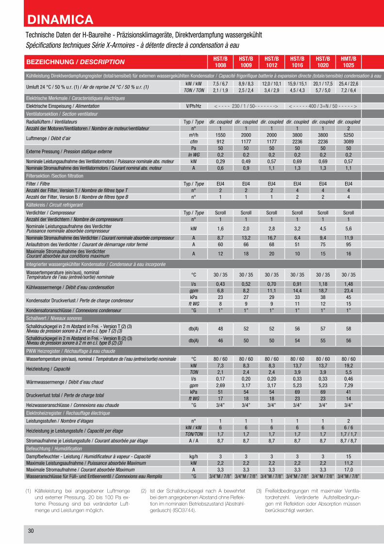
�0
(1) Kälteleistung bei angegebener LuftmengeundexternerPressung. 20bis 100Pa ex-terne Pressung sind bei veränderter Luft-mengeundLeistungenmöglich.
(2) Ist der Schalldruckpegel nach A bewehrtetbeidemangegebenenAbstandohneReflek-tionimnominalenBetriebszustand(Abstrahl-geräusch)(ISO3744).
(3) Freifeldbedingungen mit maximaler Ventila-tordrehzehl. Veränderte Aufstellbedingun-genmitReflektionoderAbsorptionmüssenberücksichtigtwerden.
BEZEICHNUNG / DESCRIPTION HST/B1008
HST/B1009
HST/B1012
HST/B1016
HST/B1020
HMT/B1025
HMT/B1030
HMT/B1036
HMT/B1041
HMT/B1053
HMT/B1066
HMT/B2031
HMT/B2041
HMT/B2055
HMT/B2064
HMT/B2074
HMT/B2083
HLT/B2104
HLT/B2134
Kühlleistung Direktverdampfungregister (total/sensibel) für externen wassergekühlten Kondensator / Capacité frigorifique batterie à expansion directe (totale/sensible) condensation à eau
Umluft �� °C / �0 % u.r. (1) / Air de reprise 24 °C / 50 % u.r. (1)kW / kW �,� / �,� �,� / �,� 1�,0 / 10,1 1�,� / 1�,1 �0,1 / 1�,� ��,� / ��,� �0,� / ��,1 ��,� / �0,� �0,� / ��,� ��,� / ��,1 ��,1 / ��,� �1,� / �0,� �1,� / �1,1 ��,� / ��,0 ��,� / ��,� ��,�/ ��,0 ��,� / ��,� 10�,0 / 10�,0 1��,� / 1��,�
TON / TON �,1 / 1,� �,� / �,� �,� / �,� �,� / �,� �,� / �,0 �,� / �,� �,� / �,� 10,1 / �,� 11,� / 10,1 1�,0 / 1�,1 1�,� / 1�,1 �,� / �,� 11,� / 11,� 1�,� / 1�,� 1�,� / 1�,0 �1,0 / �1,0 ��,� / ��,� ��,� / ��,� ��,0 / ��,0
Elektrische Merkmale / Caracteristiques électriques
Elektrische Einspeisung / Alimentation V/Ph/Hz < - - - - ��0 / 1 / �0- - - - - - -> < - - - - - �00 / �+N / �0 - - - - - > < - - - - - - -- - - - - - - - - - - - - - - - - - - - - - - - - - - - - - - - - - - - - - - - - �00 / �+N / �0 - - - - - - -- - - - - - - - - - - - - - - - - - - - - - - - - - - - - - - - - - - - - - - - ->
Ventilatorsektion / Section ventilateur
Radiallüftern / Ventilateurs Typ / Type dir. coupled dir. coupled dir. coupled dir. coupled dir. coupled dir. coupled dir. coupled dir. coupled dir. coupled dir. coupled dir. coupled dir. coupled dir. coupled dir. coupled dir. coupled dir. coupled dir. coupled dir. coupled dir. coupledAnzahl der Motoren/Ventilatoren / Nombre de moteur/ventilateur n° 1 1 1 1 1 � � � � � � � � � � � � � �
Luftmenge / Débit d’airm³/h 1��0 �000 �000 ��00 ��00 ���0 ���0 ��00 ��00 10�00 11��0 ���0 ��00 10�00 11��0 1��00 1��00 1�000 ��000cfm �1� 11�� 11�� ���� ���� �0�� �0�� ���� ���� �001 ��1� �0�� ���� �001 ��1� ���� ���� 10��0 1�1�0
Externe Pressung / Pression statique externePa �0 �0 �0 �0 �0 �0 �0 �0 �0 �0 �0 �0 �0 �0 �0 �0 �0 �0 �0
In WG 0,� 0,� 0,� 0,� 0,� 0,� 0,� 0,� 0,� 0,� 0,� 0,� 0,� 0,� 0,� 0,� 0,� 0,� 0,�Nominale Leistungsaufnahme des Ventilatormotors / Puissance nominale abs. moteur kW 0,�� 0,�� 0,�� 0,�� 0,�� 0,�� 0,�� 0,�� 0,�� 0,�� 0,�� 0,�� 0,�� 0,�� 0,�� 0,�� 0,�� 0,�� 0,��Nominale Stromaufnahme des Ventilatormotors / Courant nominal abs. moteur A 0,� 0,� 1,1 1,� 1,� 1,1 1,1 1,� 1,� 1,� 1,� 1,1 1,� 1,� 1,� 1,� 1,� 1,� 1,�
Filtersektion /Section filtration
Filter / Filtre Typ / Type EU� EU� EU� EU� EU� EU� EU� EU� EU� EU� EU� EU� EU� EU� EU� EU� EU� EU� EU�Anzahl der Filter, Version T / Nombre de filtres type T n° � � � � � � � � � � � � � � � � � � 10Anzahl der Filter, Version B / Nombre de filtres type B n° 1 1 1 � � � � � � � � � � � � � � 10 10
Kältekreis / Circuit refrigerant
Verdichter / Compresseur Typ / Type Scroll Scroll Scroll Scroll Scroll Scroll Scroll Scroll Scroll Scroll Scroll Scroll Scroll Scroll Scroll Scroll Scroll Scroll ScrollAnzahl der Verdichtern / Nombre de compresseurs n° 1 1 1 1 1 1 1 1 1 1 1 � � � � � � � �Nominale Leistungsaufnahme des VerdichterPuissance nominale absorbée compresseur kW 1,� �,0 �,� �,� �,� �,� �,� �,� �,� 11,� 1�,� �,� �,� �,� �,� �,� �,� 11,� 1�,�
Nominale Stromaufnahme des Verdichter / Courant nominale absorbée compresseur A �,� 1�,� 1�,� �,� �,� 11,� 1�,1 1�,0 1�,� ��,1 ��,� �,� �,� 1�,� 1�,� 1�,� 1�,0 ��,� ��,�Anlaufstrom des Verdichter / Courant de démarrage rotor fermé A �0 �� �� �1 �� �� 111 11� 11� 1�� ��� �1 �� �� 111 11� 11� 1�� ���Maximale Stromaufnahme des VerdichterCourant absorbée aux conditions maximum A 1� 1� �0 10 1� 1� �1 �� �� �� �0 10 1� 1� �1 �� �� �� �0
Integrierter wassergekühlter Kondensator / Condenseur à eau incorporée
Wassertemperature (ein/aus), nominalTempérature de l’eau (entreé/sortie) nominale °C �0 / �� �0 / �� �0 / �� �0 / �� �0 / �� �0 / �� �0 / �� �0 / �� �0 / �� �0 / �� �0 / �� �0 / �� �0 / �� �0 / �� �0 / �� �0 / �� �0 / �� �0 / �� �0 / ��
Kühlwassermenge / Débit d’eau condensationl/s 0,�� 0,�� 0,�0 0,�1 1,1� 1,�� 1,�� �,0� �,�� �,0� �,�� 1,�� �,1� �,�� �,�� �,�� �,�� �,�0 �,0�
gpm �,� �,� 11,1 1�,� 1�,� ��,� ��,� ��,� ��,� ��,� �1,1 ��,1 ��,� ��,� ��,� �1,� ��,1 ��,1 11�,�
Kondensator Druckverlust / Perte de charge condenseurkPa �� �� �� �� �� �� �� �� �� �� �� �1 �0 �� �� �� �� �1 ��
ft WG � � � 11 1� 1� 11 1� 1� 1� 1� 10 1� 1� 1� 1� 1� 1� 1�Kondensatoranschlüsse / Connexions condenseur ”G 1” 1” 1” 1” 1” 1” 1” 1” 1” 1” 1”1/� � x 1” � x 1” � x 1” � x 1” � x 1” � x 1” � x 1” � x 1”1/�
Schallwert / Niveaux sonores
Schalldruckpegel in � m Abstand in Frei. - Version T (�) (�)Niveau de pression sonore à 2 m en c.l. type T (2) (3) db(A) �� �� �� �� �� �� �� �� �� �� �� �� �� �0 �� �� �� �� �0
Schalldruckpegel in � m Abstand in Frei. - Version B (�) (�)Niveau de pression sonore à 2 m en c.l. type B (2) (3) db(A) �� �0 �0 �� �� �� �� �� �� �0 �0 �� �� �� �0 �0 �0 �� ��
PWW Heizregister / Réchauffage à eau chaude
Wassertemperature (ein/aus), nominal / Température de l’eau (entreé/sortie) nominale °C �0 / �0 �0 / �0 �0 / �0 �0 / �0 �0 / �0 �0 / �0 �0 / �0 �0 / �0 �0 / �0 �0 / �0 �0 / �0 �0 / �0 �0 / �0 �0 / �0 �0 / �0 �0 / �0 �0 / �0 �0 / �0 �0 / �0
Heizleistung / CapacitékW �,� �,� �,� 1�,� 1�,� 1�,� 1�,� ��,� ��,� ��,� ��,� 1�,� ��,� ��,� ��,� ��,� ��,� �1,� ��,�TON �,1 �,� �,� �,� �,� �,� �,� �,� �,� 10,� 1�,0 �,� �,� 10,� 1�,� 1�,0 1�,0 1�,� ��,�
Wärmwassermenge / Débit d’eau chaudl/s 0,1� 0,�0 0,�0 0,�� 0,�� 0,�� 0,�� 0,�� 0,�� 0,�0 1,01 0,�� 0,�� 0,�0 1,01 1,�� 1,�� 1,�� 1,��
gpm �,�� �,1� �,1� �,�� �,�� �,�� �,�� �,�� �,�� 1�,�� 1�,01 �,�� �,�� 1�,�� 1�,01 1�,�� 1�,�� ��,�� ��,�0
Druckverlust total / Perte de charge totalkPa �1 �� �� �� �� �1 �1 �� �� �1 �� �1 �� �1 �� �� �� �� ��
ft WG 1� 1� 1� �� �� 1� 1� 1� 1� 1� 1� 1� 1� 1� 1� 1� 1� 1� �1Heizwasseranschlüsse / Connexions eau chaude ”G �/�” �/�” �/�” �/�” �/�” �/�” �/�” �/�” �/�” 1” 1” �/�” �/�” 1” 1” 1” 1” 1” 1”1/�
Elektroheizregister / Rechauffage électrique
Leistungsstufen / Nombre d’étages n° 1 1 1 1 1 � � � � � � � � � � � � � �
Heizleistung je Leistungsstufe / Capacité per étagekW / kW � � � � � � / � � / � � / � � / � � / � � / � � / � � / � � / � � / � 1� / 1� 1� / 1� 1� / 1� 1� / 1�TON/TON 1,� 1,� 1,� 1,� 1,� 1,� / 1,� 1,� / 1,� 1,� / �,� 1,� / �,� 1,� / �,� 1,� / �,� 1,� / �,� 1,� / �,� 1,� / �,� 1,� / �,� �,� / �,� �,� / �,� �,� / �,� �,� / �,�
Stromaufnahme je Leistungsstufe / Courant absorbée par étage A / A �,� �,� �,� �,� �,� �,� / �,� �,� / �,� �,� / 1�,0 �,� / 1�,0 �,� / 1�,0 �,� / 1�,0 �,� / 1�,0 �,� / 1�,0 �,� / 1�,0 �,� / 1�,0 1�,1 / 1�,1 1�,1 / 1�,1 1�,1 / 1�,1 1�,1 / 1�,1
Befeuchtung / Humidification
Dampfbefeuchter - Leistung / Humidificateur à vapeur - Capacité kg/h � � � � � 1� 1� 1� 1� 1� 1� 1� 1� 1� 1� 1� 1� 1� 1�Maximale Leistungsaufnahme / Puissance absorbée Maximum kW �,� �,� �,� �,� �,� 11,� 11,� 11,� 11,� 11,� 11,� 11,� 11,� 11,� 11,� 11,� 11,� 11,� 11,�Maximale Stromaufnahme / Courant absorbée Maximum A �,� �,� �,� �,� �,� 1�,0 1�,0 1�,0 1�,0 1�,0 1�,0 1�,0 1�,0 1�,0 1�,0 1�,0 1�,0 1�,0 1�,0Wasseranschlüsse für Füll- und Entleerventil / Connexions eau Remplis ”G �/�”M / �/�” �/�”M / �/�” �/�”M / �/�” �/�”M / �/�” �/�”M / �/�” �/�”M / �/�” �/�”M / �/�” �/�”M / �/�” �/�”M / �/�” �/�”M / �/�” �/�”M / �/�” �/�”M / �/�” �/�”M / �/�” �/�”M / �/�” �/�”M / �/�” �/�”M / �/�” �/�”M / �/�” �/�”M / �/�” �/�”M / �/�”
Technische Daten der H-Baureihe - Präzisionsklimageräte, Direktverdampfung wassergekühltSpécifications techniques Série X-Armoires - à détente directe à condensation à eau
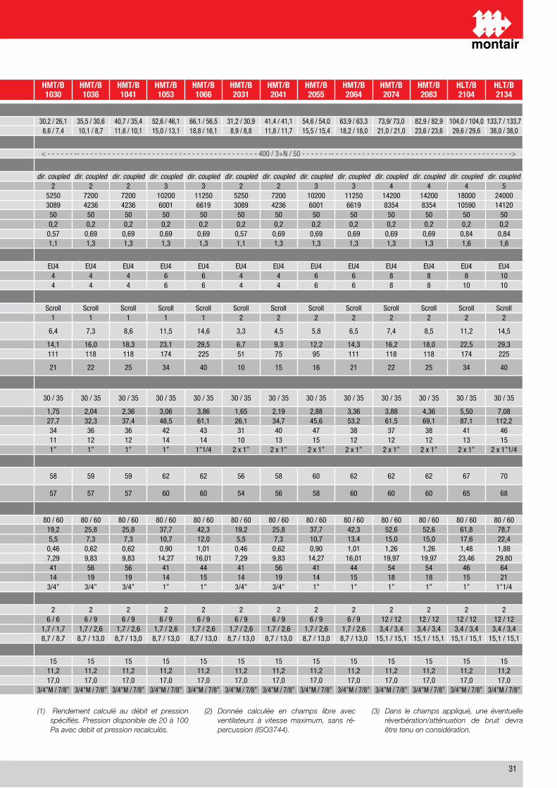
�1
(1) Rendement calculé au débit et pression spécifiés. Pression disponible de 20 à 100 Pa avec debit et pression recalculés.
(2) Donnée calculée en champs libre avec ventilateurs à vitesse maximum, sans ré-percussion (ISO3744).
(3) Dans le champs appliqué, une éventuelle réverbération/atténuation de bruit devra être tenu en considération.
BEZEICHNUNG / DESCRIPTION HST/B1008
HST/B1009
HST/B1012
HST/B1016
HST/B1020
HMT/B1025
HMT/B1030
HMT/B1036
HMT/B1041
HMT/B1053
HMT/B1066
HMT/B2031
HMT/B2041
HMT/B2055
HMT/B2064
HMT/B2074
HMT/B2083
HLT/B2104
HLT/B2134
Kühlleistung Direktverdampfungregister (total/sensibel) für externen wassergekühlten Kondensator / Capacité frigorifique batterie à expansion directe (totale/sensible) condensation à eau
Umluft �� °C / �0 % u.r. (1) / Air de reprise 24 °C / 50 % u.r. (1)kW / kW �,� / �,� �,� / �,� 1�,0 / 10,1 1�,� / 1�,1 �0,1 / 1�,� ��,� / ��,� �0,� / ��,1 ��,� / �0,� �0,� / ��,� ��,� / ��,1 ��,1 / ��,� �1,� / �0,� �1,� / �1,1 ��,� / ��,0 ��,� / ��,� ��,�/ ��,0 ��,� / ��,� 10�,0 / 10�,0 1��,� / 1��,�
TON / TON �,1 / 1,� �,� / �,� �,� / �,� �,� / �,� �,� / �,0 �,� / �,� �,� / �,� 10,1 / �,� 11,� / 10,1 1�,0 / 1�,1 1�,� / 1�,1 �,� / �,� 11,� / 11,� 1�,� / 1�,� 1�,� / 1�,0 �1,0 / �1,0 ��,� / ��,� ��,� / ��,� ��,0 / ��,0
Elektrische Merkmale / Caracteristiques électriques
Elektrische Einspeisung / Alimentation V/Ph/Hz < - - - - ��0 / 1 / �0- - - - - - -> < - - - - - �00 / �+N / �0 - - - - - > < - - - - - - -- - - - - - - - - - - - - - - - - - - - - - - - - - - - - - - - - - - - - - - - - �00 / �+N / �0 - - - - - - -- - - - - - - - - - - - - - - - - - - - - - - - - - - - - - - - - - - - - - - - ->
Ventilatorsektion / Section ventilateur
Radiallüftern / Ventilateurs Typ / Type dir. coupled dir. coupled dir. coupled dir. coupled dir. coupled dir. coupled dir. coupled dir. coupled dir. coupled dir. coupled dir. coupled dir. coupled dir. coupled dir. coupled dir. coupled dir. coupled dir. coupled dir. coupled dir. coupledAnzahl der Motoren/Ventilatoren / Nombre de moteur/ventilateur n° 1 1 1 1 1 � � � � � � � � � � � � � �
Luftmenge / Débit d’airm³/h 1��0 �000 �000 ��00 ��00 ���0 ���0 ��00 ��00 10�00 11��0 ���0 ��00 10�00 11��0 1��00 1��00 1�000 ��000cfm �1� 11�� 11�� ���� ���� �0�� �0�� ���� ���� �001 ��1� �0�� ���� �001 ��1� ���� ���� 10��0 1�1�0
Externe Pressung / Pression statique externePa �0 �0 �0 �0 �0 �0 �0 �0 �0 �0 �0 �0 �0 �0 �0 �0 �0 �0 �0
In WG 0,� 0,� 0,� 0,� 0,� 0,� 0,� 0,� 0,� 0,� 0,� 0,� 0,� 0,� 0,� 0,� 0,� 0,� 0,�Nominale Leistungsaufnahme des Ventilatormotors / Puissance nominale abs. moteur kW 0,�� 0,�� 0,�� 0,�� 0,�� 0,�� 0,�� 0,�� 0,�� 0,�� 0,�� 0,�� 0,�� 0,�� 0,�� 0,�� 0,�� 0,�� 0,��Nominale Stromaufnahme des Ventilatormotors / Courant nominal abs. moteur A 0,� 0,� 1,1 1,� 1,� 1,1 1,1 1,� 1,� 1,� 1,� 1,1 1,� 1,� 1,� 1,� 1,� 1,� 1,�
Filtersektion /Section filtration
Filter / Filtre Typ / Type EU� EU� EU� EU� EU� EU� EU� EU� EU� EU� EU� EU� EU� EU� EU� EU� EU� EU� EU�Anzahl der Filter, Version T / Nombre de filtres type T n° � � � � � � � � � � � � � � � � � � 10Anzahl der Filter, Version B / Nombre de filtres type B n° 1 1 1 � � � � � � � � � � � � � � 10 10
Kältekreis / Circuit refrigerant
Verdichter / Compresseur Typ / Type Scroll Scroll Scroll Scroll Scroll Scroll Scroll Scroll Scroll Scroll Scroll Scroll Scroll Scroll Scroll Scroll Scroll Scroll ScrollAnzahl der Verdichtern / Nombre de compresseurs n° 1 1 1 1 1 1 1 1 1 1 1 � � � � � � � �Nominale Leistungsaufnahme des VerdichterPuissance nominale absorbée compresseur kW 1,� �,0 �,� �,� �,� �,� �,� �,� �,� 11,� 1�,� �,� �,� �,� �,� �,� �,� 11,� 1�,�
Nominale Stromaufnahme des Verdichter / Courant nominale absorbée compresseur A �,� 1�,� 1�,� �,� �,� 11,� 1�,1 1�,0 1�,� ��,1 ��,� �,� �,� 1�,� 1�,� 1�,� 1�,0 ��,� ��,�Anlaufstrom des Verdichter / Courant de démarrage rotor fermé A �0 �� �� �1 �� �� 111 11� 11� 1�� ��� �1 �� �� 111 11� 11� 1�� ���Maximale Stromaufnahme des VerdichterCourant absorbée aux conditions maximum A 1� 1� �0 10 1� 1� �1 �� �� �� �0 10 1� 1� �1 �� �� �� �0
Integrierter wassergekühlter Kondensator / Condenseur à eau incorporée
Wassertemperature (ein/aus), nominalTempérature de l’eau (entreé/sortie) nominale °C �0 / �� �0 / �� �0 / �� �0 / �� �0 / �� �0 / �� �0 / �� �0 / �� �0 / �� �0 / �� �0 / �� �0 / �� �0 / �� �0 / �� �0 / �� �0 / �� �0 / �� �0 / �� �0 / ��
Kühlwassermenge / Débit d’eau condensationl/s 0,�� 0,�� 0,�0 0,�1 1,1� 1,�� 1,�� �,0� �,�� �,0� �,�� 1,�� �,1� �,�� �,�� �,�� �,�� �,�0 �,0�
gpm �,� �,� 11,1 1�,� 1�,� ��,� ��,� ��,� ��,� ��,� �1,1 ��,1 ��,� ��,� ��,� �1,� ��,1 ��,1 11�,�
Kondensator Druckverlust / Perte de charge condenseurkPa �� �� �� �� �� �� �� �� �� �� �� �1 �0 �� �� �� �� �1 ��
ft WG � � � 11 1� 1� 11 1� 1� 1� 1� 10 1� 1� 1� 1� 1� 1� 1�Kondensatoranschlüsse / Connexions condenseur ”G 1” 1” 1” 1” 1” 1” 1” 1” 1” 1” 1”1/� � x 1” � x 1” � x 1” � x 1” � x 1” � x 1” � x 1” � x 1”1/�
Schallwert / Niveaux sonores
Schalldruckpegel in � m Abstand in Frei. - Version T (�) (�)Niveau de pression sonore à 2 m en c.l. type T (2) (3) db(A) �� �� �� �� �� �� �� �� �� �� �� �� �� �0 �� �� �� �� �0
Schalldruckpegel in � m Abstand in Frei. - Version B (�) (�)Niveau de pression sonore à 2 m en c.l. type B (2) (3) db(A) �� �0 �0 �� �� �� �� �� �� �0 �0 �� �� �� �0 �0 �0 �� ��
PWW Heizregister / Réchauffage à eau chaude
Wassertemperature (ein/aus), nominal / Température de l’eau (entreé/sortie) nominale °C �0 / �0 �0 / �0 �0 / �0 �0 / �0 �0 / �0 �0 / �0 �0 / �0 �0 / �0 �0 / �0 �0 / �0 �0 / �0 �0 / �0 �0 / �0 �0 / �0 �0 / �0 �0 / �0 �0 / �0 �0 / �0 �0 / �0
Heizleistung / CapacitékW �,� �,� �,� 1�,� 1�,� 1�,� 1�,� ��,� ��,� ��,� ��,� 1�,� ��,� ��,� ��,� ��,� ��,� �1,� ��,�TON �,1 �,� �,� �,� �,� �,� �,� �,� �,� 10,� 1�,0 �,� �,� 10,� 1�,� 1�,0 1�,0 1�,� ��,�
Wärmwassermenge / Débit d’eau chaudl/s 0,1� 0,�0 0,�0 0,�� 0,�� 0,�� 0,�� 0,�� 0,�� 0,�0 1,01 0,�� 0,�� 0,�0 1,01 1,�� 1,�� 1,�� 1,��
gpm �,�� �,1� �,1� �,�� �,�� �,�� �,�� �,�� �,�� 1�,�� 1�,01 �,�� �,�� 1�,�� 1�,01 1�,�� 1�,�� ��,�� ��,�0
Druckverlust total / Perte de charge totalkPa �1 �� �� �� �� �1 �1 �� �� �1 �� �1 �� �1 �� �� �� �� ��
ft WG 1� 1� 1� �� �� 1� 1� 1� 1� 1� 1� 1� 1� 1� 1� 1� 1� 1� �1Heizwasseranschlüsse / Connexions eau chaude ”G �/�” �/�” �/�” �/�” �/�” �/�” �/�” �/�” �/�” 1” 1” �/�” �/�” 1” 1” 1” 1” 1” 1”1/�
Elektroheizregister / Rechauffage électrique
Leistungsstufen / Nombre d’étages n° 1 1 1 1 1 � � � � � � � � � � � � � �
Heizleistung je Leistungsstufe / Capacité per étagekW / kW � � � � � � / � � / � � / � � / � � / � � / � � / � � / � � / � � / � 1� / 1� 1� / 1� 1� / 1� 1� / 1�TON/TON 1,� 1,� 1,� 1,� 1,� 1,� / 1,� 1,� / 1,� 1,� / �,� 1,� / �,� 1,� / �,� 1,� / �,� 1,� / �,� 1,� / �,� 1,� / �,� 1,� / �,� �,� / �,� �,� / �,� �,� / �,� �,� / �,�
Stromaufnahme je Leistungsstufe / Courant absorbée par étage A / A �,� �,� �,� �,� �,� �,� / �,� �,� / �,� �,� / 1�,0 �,� / 1�,0 �,� / 1�,0 �,� / 1�,0 �,� / 1�,0 �,� / 1�,0 �,� / 1�,0 �,� / 1�,0 1�,1 / 1�,1 1�,1 / 1�,1 1�,1 / 1�,1 1�,1 / 1�,1
Befeuchtung / Humidification
Dampfbefeuchter - Leistung / Humidificateur à vapeur - Capacité kg/h � � � � � 1� 1� 1� 1� 1� 1� 1� 1� 1� 1� 1� 1� 1� 1�Maximale Leistungsaufnahme / Puissance absorbée Maximum kW �,� �,� �,� �,� �,� 11,� 11,� 11,� 11,� 11,� 11,� 11,� 11,� 11,� 11,� 11,� 11,� 11,� 11,�Maximale Stromaufnahme / Courant absorbée Maximum A �,� �,� �,� �,� �,� 1�,0 1�,0 1�,0 1�,0 1�,0 1�,0 1�,0 1�,0 1�,0 1�,0 1�,0 1�,0 1�,0 1�,0Wasseranschlüsse für Füll- und Entleerventil / Connexions eau Remplis ”G �/�”M / �/�” �/�”M / �/�” �/�”M / �/�” �/�”M / �/�” �/�”M / �/�” �/�”M / �/�” �/�”M / �/�” �/�”M / �/�” �/�”M / �/�” �/�”M / �/�” �/�”M / �/�” �/�”M / �/�” �/�”M / �/�” �/�”M / �/�” �/�”M / �/�” �/�”M / �/�” �/�”M / �/�” �/�”M / �/�” �/�”M / �/�”
Technische Daten der H-Baureihe - Präzisionsklimageräte, Direktverdampfung wassergekühltSpécifications techniques Série X-Armoires - à détente directe à condensation à eau
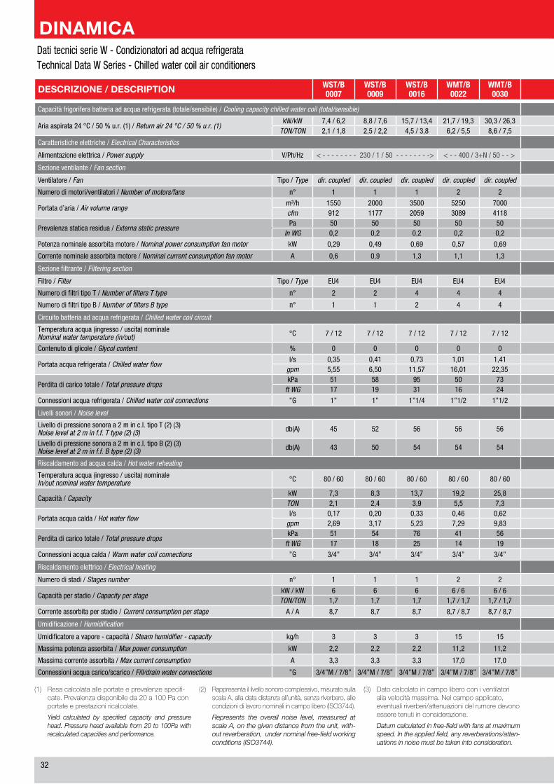
��
DESCRIZIONE / DESCRIPTION WST/B0007
WST/B0009
WST/B0016
WMT/B0022
WMT/B0030
WMT/B0040
WMT/B0046
WMT/B0060
WLT/B0076
WLT/B0102 BEZEICHNUNG / DESCRIPTION
Capacità frigorifera batteria ad acqua refrigerata (totale/sensibile) / Cooling capacity chilled water coil (total/sensible) Kälteleistung (total/sensibel) / Capacité frigorifique batterie eau glacée (totale/sensible)
Aria aspirata �� °C / �0 % u.r. (1) / Return air 24 °C / 50 % u.r. (1)kW/kW �,� / �,� �,� / �,� 1�,� / 1�,� �1,� / 1�,� �0,� / ��,� �0,� / ��,1 ��,� / �0,� �0,� / �1,� ��,� / �0,0 10�,� / �1,� kW/kW
Umluft �� °C / �0 % u.r. (1) / Air de reprise 24 °C / 50 % u.r. (1)TON/TON �,1 / 1,� �,� / �,� �,� / �,� �,� / �,� �,� / �,� 11,� / 10,� 1�,� / 11,� 1�,1 / 1�,� �1,� /1�,� ��,1 / ��,0 TON/TON
Caratteristiche elettriche / Electrical Characteristics Elektrische Merkmale / Caracteristiques électriques
Alimentazione elettrica / Power supply V/Ph/Hz < - - - - - - - - ��0 / 1 / �0 - - - - - - - -> < - - �00 / �+N / �0 - - > < - - - - - - - - - - - - - - - - �00 / �+N / �0 - - - - - - - - - - - - - - - -> V/Ph/Hz Elektrische Einspeisung / Alimentation
Sezione ventilante / Fan section Ventilatorsektion / Section ventilateur
Ventilatore / Fan Tipo / Type dir. coupled dir. coupled dir. coupled dir. coupled dir. coupled dir. coupled dir. coupled dir. coupled dir. coupled dir. coupled Typ / Type Radiallüftern / Ventilateurs
Numero di motori/ventilatori / Number of motors/fans n° 1 1 1 � � � � � � � n° Anzahl der Motoren/Ventilatoren / Nombre de moteur/ventilateur
Portata d’aria / Air volume rangem³/h 1��0 �000 ��00 ���0 �000 ��00 10�00 1��00 1��00 ���00 m³/h
Luftmenge / Débit d’aircfm �1� 11�� �0�� �0�� �11� ���� ���� �001 10��� 1���� cfm
Prevalenza statica residua / Externa static pressurePa �0 �0 �0 �0 �0 �0 �0 �0 �0 �0 Pa
Externe Pressung / Pression statique externeIn WG 0,� 0,� 0,� 0,� 0,� 0,� 0,� 0,� 0,� 0,� In WG
Potenza nominale assorbita motore / Nominal power consumption fan motor kW 0,�� 0,�� 0,�� 0,�� 0,�� 0,�� 0,�� 0,�� 0,�� 0,�� kW Nominale Leistungsaufnahme des Ventilatormotors / Puissance nominale abs. moteur
Corrente nominale assorbita motore / Nominal current consumption fan motor A 0,� 0,� 1,� 1,1 1,� 1,� 1,� 1,� 1,� 1,� A Nominale Stromaufnahme des Ventilatormotors / Courant nominal abs. moteur
Sezione filtrante / Filtering section Filtersektion /Section filtration
Filtro / Filter Tipo / Type EU� EU� EU� EU� EU� EU� EU� EU� EU� EU� Typ / Type Filter / Filtre
Numero di filtri tipo T / Number of filters T type n° � � � � � � � � � 10 n° Anzahl der Filter, Version T / Nombre de filtres type T
Numero di filtri tipo B / Number of filters B type n° 1 1 � � � � � � 10 10 n° Anzahl der Filter, Version B / Nombre de filtres type B
Circuito batteria ad acqua refrigerata / Chilled water coil circuit Kältekreis / Circuit refrigerant
Temperatura acqua (ingresso / uscita) nominaleNominal water temperature (in/out) °C � / 1� � / 1� � / 1� � / 1� � / 1� � / 1� � / 1� � / 1� � / 1� � / 1� °C Wassertemperature (ein / aus) nominal
Temperature d’eau entrée (entrée / sortie)
Contenuto di glicole / Glycol content % 0 0 0 0 0 0 0 0 0 0 % Glycolanteil / Glycol
Portata acqua refrigerata / Chilled water flowl/s 0,�� 0,�1 0,�� 1,01 1,�1 1,�� �,1� �,�0 �,�� �,�� l/s
Kaltwassermenge / Débit d’eau glacéegpm �,�� �,�0 11,�� 1�,01 ��,�� ��,�� ��,�� ��,�� ��,�� ��,1� gpm
Perdita di carico totale / Total pressure dropskPa �1 �� �� �0 �� �� �0 �� �� 101 kPa
Druckverlust total / Perte de charge totalft WG 1� 1� �1 1� �� 1� 1� �� �1 �� ft WG
Connessioni acqua refrigerata / Chilled water coil connections ”G 1” 1” 1”1/� 1”1/� 1”1/� 1”1/� 1”1/� �” �”1/� �”1/� ”G Kaltwasseranschlüsse / Connexions eau glacée
Livelli sonori / Noise level Schallwert / Niveaux sonores
Livello di pressione sonora a � m in c.l. tipo T (�) (�)Noise level at 2 m in f.f. T type (2) (3) db(A) �� �� �� �� �� �� �� �0 �� �� db(A) Schalldruckpegel in � m Abstand in Frei. - Version T (�) (�)
Niveau de pression sonore à 2 m en c.l. type T (2) (3)Livello di pressione sonora a � m in c.l. tipo B (�) (�)Noise level at 2 m in f.f. B type (2) (3) db(A) �� �0 �� �� �� �� �� �� �� �� db(A) Schalldruckpegel in � m Abstand in Frei. - Version B (�) (�)
Niveau de pression sonore à 2 m en c.l. type B (2) (3)
Riscaldamento ad acqua calda / Hot water reheating PWW Heizregister / Réchauffage à eau chaude
Temperatura acqua (ingresso / uscita) nominaleIn/out nominal water temperature °C �0 / �0 �0 / �0 �0 / �0 �0 / �0 �0 / �0 �0 / �0 �0 / �0 �0 / �0 �0 / �0 �0 / �0 °C Wassertemperature (ein/aus), nominal
Température de l’eau (entreé/sortie) nominale
Capacità / CapacitykW �,� �,� 1�,� 1�,� ��,� ��,� ��,� ��,� �1,� ��,� kW
Heizleistung / CapacitéTON �,1 �,� �,� �,� �,� 10,� 1�,0 1�,0 1�,� ��,� TON
Portata acqua calda / Hot water flowl/s 0,1� 0,�0 0,�� 0,�� 0,�� 0,�0 1,01 1,�� 1,�� 1,�� l/s
Wärmwassermenge / Débit d’eau chaudgpm �,�� �,1� �,�� �,�� �,�� 1�,�� 1�,01 1�,�� ��,�� ��,�0 gpm
Perdita di carico totale / Total pressure dropskPa �1 �� �� �1 �� �1 �� �� �� �� kPa
Druckverlust total / Perte de charge totalft WG 1� 1� �� 1� 1� 1� 1� 1� 1� �1 ft WG
Connessioni acqua calda / Warm water coil connections ”G �/�” �/�” �/�” �/�” �/�” 1” 1” 1” 1” 1”1/� ”G Heizwasseranschlüsse / Connexions eau chaude
Riscaldamento elettrico / Electrical heating Elektroheizregister / Rechauffage électrique
Numero di stadi / Stages number n° 1 1 1 � � � � � � � n° Leistungsstufen / Nombre d’étages
Capacità per stadio / Capacity per stagekW / kW � � � � / � � / � � / � � / � � / � 1� / 1� 1� / 1� kW / kW
Heizleistung je Leistungsstufe / Capacité per étageTON/TON 1,� 1,� 1,� 1,� / 1,� 1,� / 1,� 1,� / �,� 1,� / �,� �,� / �,� �,� / �,� �,� / �,� TON/TON
Corrente assorbita per stadio / Current consumption per stage A / A �,� �,� �,� �,� / �,� �,� / �,� �,� / 1�,0 �,� / 1�,0 �,� / 1�,0 1�,1 / 1�,1 1�,1 / 1�,1 A / A Stromaufnahme je Leistungsstufe / Courant absorbée par étage
Umidificazione / Humidification Befeuchtung / Humidification
Umidificatore a vapore - capacità / Steam humidifier - capacity kg/h � � � 1� 1� 1� 1� 1� 1� 1� kg/h Dampfbefeuchter - Leistung / Humidificateur à vapeur - Capacité
Massima potenza assorbita / Max power consumption kW �,� �,� �,� 11,� 11,� 11,� 11,� 11,� 11,� 11,� kW Maximale Leistungsaufnahme / Puissance absorbée Maximum
Massima corrente assorbita / Max current consumption A �,� �,� �,� 1�,0 1�,0 1�,0 1�,0 1�,0 1�,0 1�,0 A Maximale Stromaufnahme / Courant absorbée Maximum
Connessioni acqua carico/scarico / Fill/drain water connections ”G �/�”M / �/�” �/�”M / �/�” �/�”M / �/�” �/�”M / �/�” �/�”M / �/�” �/�”M / �/�” �/�”M / �/�” �/�”M / �/�” �/�”M / �/�” �/�”M / �/�” ”G / mm Wasseranschlüsse für Füll- und Entleerventil / Connexions eau Remplis
(1) Resacalcolataalleportateeprevalenzespecifi-cate.Prevalenzadisponibileda20a100Paconportateeprestazioniricalcolate.
Yield calculated by specified capacity and pressure head. Pressure head available from 20 to 100Pa with recalculated capacities and performance.
(2) Rappresentaililvellosonorocomplessivo,misuratosullascalaA,alladatadistanzaall’unità,senzariverbero,allecondizionidilavoronominaliincampolibero(ISO3744).
Represents the overall noise level, measured at scale A, on the given distance from the unit, with-out reverberation, under nominal free-field working conditions (ISO3744).
(3) Datocalcolatoincampoliberoconiventilatoriallavelocitàmassima.Nelcampoapplicato,eventualiriverberi/attenuazionidelrumoredevonoesseretenutiinconsiderazione.
Datum calculated in free-field with fans at maximum speed. In the applied field, any reverberations/atten-uations in noise must be taken into consideration.
Dati tecnici serie W - Condizionatori ad acqua refrigerataTechnical Data W Series - Chilled water coil air conditioners
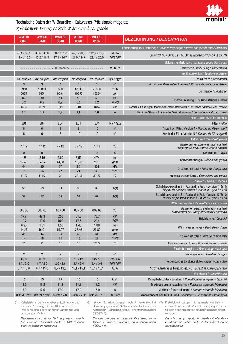
��
DESCRIZIONE / DESCRIPTION WST/B0007
WST/B0009
WST/B0016
WMT/B0022
WMT/B0030
WMT/B0040
WMT/B0046
WMT/B0060
WLT/B0076
WLT/B0102 BEZEICHNUNG / DESCRIPTION
Capacità frigorifera batteria ad acqua refrigerata (totale/sensibile) / Cooling capacity chilled water coil (total/sensible) Kälteleistung (total/sensibel) / Capacité frigorifique batterie eau glacée (totale/sensible)
Aria aspirata �� °C / �0 % u.r. (1) / Return air 24 °C / 50 % u.r. (1)kW/kW �,� / �,� �,� / �,� 1�,� / 1�,� �1,� / 1�,� �0,� / ��,� �0,� / ��,1 ��,� / �0,� �0,� / �1,� ��,� / �0,0 10�,� / �1,� kW/kW
Umluft �� °C / �0 % u.r. (1) / Air de reprise 24 °C / 50 % u.r. (1)TON/TON �,1 / 1,� �,� / �,� �,� / �,� �,� / �,� �,� / �,� 11,� / 10,� 1�,� / 11,� 1�,1 / 1�,� �1,� /1�,� ��,1 / ��,0 TON/TON
Caratteristiche elettriche / Electrical Characteristics Elektrische Merkmale / Caracteristiques électriques
Alimentazione elettrica / Power supply V/Ph/Hz < - - - - - - - - ��0 / 1 / �0 - - - - - - - -> < - - �00 / �+N / �0 - - > < - - - - - - - - - - - - - - - - �00 / �+N / �0 - - - - - - - - - - - - - - - -> V/Ph/Hz Elektrische Einspeisung / Alimentation
Sezione ventilante / Fan section Ventilatorsektion / Section ventilateur
Ventilatore / Fan Tipo / Type dir. coupled dir. coupled dir. coupled dir. coupled dir. coupled dir. coupled dir. coupled dir. coupled dir. coupled dir. coupled Typ / Type Radiallüftern / Ventilateurs
Numero di motori/ventilatori / Number of motors/fans n° 1 1 1 � � � � � � � n° Anzahl der Motoren/Ventilatoren / Nombre de moteur/ventilateur
Portata d’aria / Air volume rangem³/h 1��0 �000 ��00 ���0 �000 ��00 10�00 1��00 1��00 ���00 m³/h
Luftmenge / Débit d’aircfm �1� 11�� �0�� �0�� �11� ���� ���� �001 10��� 1���� cfm
Prevalenza statica residua / Externa static pressurePa �0 �0 �0 �0 �0 �0 �0 �0 �0 �0 Pa
Externe Pressung / Pression statique externeIn WG 0,� 0,� 0,� 0,� 0,� 0,� 0,� 0,� 0,� 0,� In WG
Potenza nominale assorbita motore / Nominal power consumption fan motor kW 0,�� 0,�� 0,�� 0,�� 0,�� 0,�� 0,�� 0,�� 0,�� 0,�� kW Nominale Leistungsaufnahme des Ventilatormotors / Puissance nominale abs. moteur
Corrente nominale assorbita motore / Nominal current consumption fan motor A 0,� 0,� 1,� 1,1 1,� 1,� 1,� 1,� 1,� 1,� A Nominale Stromaufnahme des Ventilatormotors / Courant nominal abs. moteur
Sezione filtrante / Filtering section Filtersektion /Section filtration
Filtro / Filter Tipo / Type EU� EU� EU� EU� EU� EU� EU� EU� EU� EU� Typ / Type Filter / Filtre
Numero di filtri tipo T / Number of filters T type n° � � � � � � � � � 10 n° Anzahl der Filter, Version T / Nombre de filtres type T
Numero di filtri tipo B / Number of filters B type n° 1 1 � � � � � � 10 10 n° Anzahl der Filter, Version B / Nombre de filtres type B
Circuito batteria ad acqua refrigerata / Chilled water coil circuit Kältekreis / Circuit refrigerant
Temperatura acqua (ingresso / uscita) nominaleNominal water temperature (in/out) °C � / 1� � / 1� � / 1� � / 1� � / 1� � / 1� � / 1� � / 1� � / 1� � / 1� °C Wassertemperature (ein / aus) nominal
Temperature d’eau entrée (entrée / sortie)
Contenuto di glicole / Glycol content % 0 0 0 0 0 0 0 0 0 0 % Glycolanteil / Glycol
Portata acqua refrigerata / Chilled water flowl/s 0,�� 0,�1 0,�� 1,01 1,�1 1,�� �,1� �,�0 �,�� �,�� l/s
Kaltwassermenge / Débit d’eau glacéegpm �,�� �,�0 11,�� 1�,01 ��,�� ��,�� ��,�� ��,�� ��,�� ��,1� gpm
Perdita di carico totale / Total pressure dropskPa �1 �� �� �0 �� �� �0 �� �� 101 kPa
Druckverlust total / Perte de charge totalft WG 1� 1� �1 1� �� 1� 1� �� �1 �� ft WG
Connessioni acqua refrigerata / Chilled water coil connections ”G 1” 1” 1”1/� 1”1/� 1”1/� 1”1/� 1”1/� �” �”1/� �”1/� ”G Kaltwasseranschlüsse / Connexions eau glacée
Livelli sonori / Noise level Schallwert / Niveaux sonores
Livello di pressione sonora a � m in c.l. tipo T (�) (�)Noise level at 2 m in f.f. T type (2) (3) db(A) �� �� �� �� �� �� �� �0 �� �� db(A) Schalldruckpegel in � m Abstand in Frei. - Version T (�) (�)
Niveau de pression sonore à 2 m en c.l. type T (2) (3)Livello di pressione sonora a � m in c.l. tipo B (�) (�)Noise level at 2 m in f.f. B type (2) (3) db(A) �� �0 �� �� �� �� �� �� �� �� db(A) Schalldruckpegel in � m Abstand in Frei. - Version B (�) (�)
Niveau de pression sonore à 2 m en c.l. type B (2) (3)
Riscaldamento ad acqua calda / Hot water reheating PWW Heizregister / Réchauffage à eau chaude
Temperatura acqua (ingresso / uscita) nominaleIn/out nominal water temperature °C �0 / �0 �0 / �0 �0 / �0 �0 / �0 �0 / �0 �0 / �0 �0 / �0 �0 / �0 �0 / �0 �0 / �0 °C Wassertemperature (ein/aus), nominal
Température de l’eau (entreé/sortie) nominale
Capacità / CapacitykW �,� �,� 1�,� 1�,� ��,� ��,� ��,� ��,� �1,� ��,� kW
Heizleistung / CapacitéTON �,1 �,� �,� �,� �,� 10,� 1�,0 1�,0 1�,� ��,� TON
Portata acqua calda / Hot water flowl/s 0,1� 0,�0 0,�� 0,�� 0,�� 0,�0 1,01 1,�� 1,�� 1,�� l/s
Wärmwassermenge / Débit d’eau chaudgpm �,�� �,1� �,�� �,�� �,�� 1�,�� 1�,01 1�,�� ��,�� ��,�0 gpm
Perdita di carico totale / Total pressure dropskPa �1 �� �� �1 �� �1 �� �� �� �� kPa
Druckverlust total / Perte de charge totalft WG 1� 1� �� 1� 1� 1� 1� 1� 1� �1 ft WG
Connessioni acqua calda / Warm water coil connections ”G �/�” �/�” �/�” �/�” �/�” 1” 1” 1” 1” 1”1/� ”G Heizwasseranschlüsse / Connexions eau chaude
Riscaldamento elettrico / Electrical heating Elektroheizregister / Rechauffage électrique
Numero di stadi / Stages number n° 1 1 1 � � � � � � � n° Leistungsstufen / Nombre d’étages
Capacità per stadio / Capacity per stagekW / kW � � � � / � � / � � / � � / � � / � 1� / 1� 1� / 1� kW / kW
Heizleistung je Leistungsstufe / Capacité per étageTON/TON 1,� 1,� 1,� 1,� / 1,� 1,� / 1,� 1,� / �,� 1,� / �,� �,� / �,� �,� / �,� �,� / �,� TON/TON
Corrente assorbita per stadio / Current consumption per stage A / A �,� �,� �,� �,� / �,� �,� / �,� �,� / 1�,0 �,� / 1�,0 �,� / 1�,0 1�,1 / 1�,1 1�,1 / 1�,1 A / A Stromaufnahme je Leistungsstufe / Courant absorbée par étage
Umidificazione / Humidification Befeuchtung / Humidification
Umidificatore a vapore - capacità / Steam humidifier - capacity kg/h � � � 1� 1� 1� 1� 1� 1� 1� kg/h Dampfbefeuchter - Leistung / Humidificateur à vapeur - Capacité
Massima potenza assorbita / Max power consumption kW �,� �,� �,� 11,� 11,� 11,� 11,� 11,� 11,� 11,� kW Maximale Leistungsaufnahme / Puissance absorbée Maximum
Massima corrente assorbita / Max current consumption A �,� �,� �,� 1�,0 1�,0 1�,0 1�,0 1�,0 1�,0 1�,0 A Maximale Stromaufnahme / Courant absorbée Maximum
Connessioni acqua carico/scarico / Fill/drain water connections ”G �/�”M / �/�” �/�”M / �/�” �/�”M / �/�” �/�”M / �/�” �/�”M / �/�” �/�”M / �/�” �/�”M / �/�” �/�”M / �/�” �/�”M / �/�” �/�”M / �/�” ”G / mm Wasseranschlüsse für Füll- und Entleerventil / Connexions eau Remplis
(1) KälteleistungbeiangegebenerLuftmengeundexternerPressung.20bis100PaexternePressungsindbeiveränderterLuftmengeundLeistungenmöglich.
Rendement calculé au débit et pression spéci-fiés. Pression disponible de 20 à 100 Pa avec debit et pression recalculés.
(2) Ist der Schalldruckpegel nach A bewehrtet beidem angegebenen Abstand ohne Reflektion imnominalen Betriebszustand (Abstrahlgeräusch)(ISO3744).
Donnée calculée en champs libre avec venti-lateurs à vitesse maximum, sans répercussion (ISO3744).
(3) FreifeldbedingungenmitmaximalerVentilator-drehzehl.VeränderteAufstellbedingungenmitRe-flektionoderAbsorptionmüssenberücksichtigtwerden.
Dans le champs appliqué, une éventuelle réver-bération/atténuation de bruit devra être tenu en considération.
Technische Daten der W-Baureihe - Kaltwasser-Präzisionsklimageräte Spécifications techniques Série W-Armoires à eau glacée
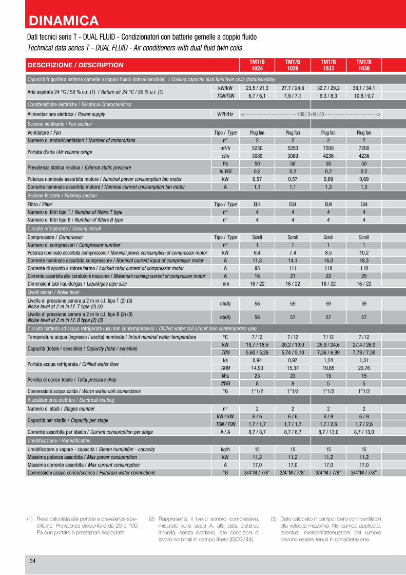
��
(1) Resacalcolataalleportateeprevalenzespe-cificate.Prevalenzadisponibileda20a100Paconportateeprestazioniricalcolate.
(2) Rappresenta il ilvello sonoro complessivo,misurato sulla scala A, alla data distanzaall’unità, senza riverbero, alle condizioni dilavoronominaliincampolibero(ISO3744).
(3) Datocalcolatoincampoliberoconiventilatoriallavelocitàmassima.Nelcampoapplicato,eventuali riverberi/attenuazioni del rumoredevonoesseretenutiinconsiderazione.
DESCRIZIONE / DESCRIPTION TMT/B1024
TMT/B1028
TMT/B1033
TMT/B1038
TMT/B1049
TMT/B1062
TMT/B2029
TMT/B2038
TMT/B2049
TMT/B2058
TMT/B2069
TMT/B2078
TLT/B2096
TLT/B2125
Capacità frigorifera batterie gemelle a doppio fluido (totale/sensibile) / Cooling capacity dual fluid twin coils (total/sensible)
Aria aspirata �� °C / �0 % u.r. (1) / Return air 24 °C / 50 % u.r. (1)kW/kW ��,� / �1,� ��,� / ��,� ��,� / ��,� ��,1 / ��,1 ��,0 / ��,� �1,� / ��,0 ��,� / ��,1 ��,� / ��,1 ��,� / ��,� ��,0 / ��,0 ��,1 / ��,1 ��,� / ��,1 ��,� / ��,� 1��,1 / 1��,1
TON/TON �,� / �,1 �,� / �,1 �,� / �,� 10,� / �,� 1�,� / 1�,� 1�,� / 1�,� �,1 / �,0 10,� / 10,� 1�,0 / 1�,0 1�,� / 1�,� 1�,� / 1�,� ��,0 / �1,� ��,� / ��,� ��,� / ��,�
Caratteristiche elettriche / Electrical Characteristics
Alimentazione elettrica / Power supply V/Ph/Hz <- - - - - - - - - - - - - - - - - - - �00 / �+N / �0 - - - - - - - - - - - - - - - - - - -> <- - - - - - - - - - - - - - - - - - - - - - - - - - - - - - - - - - - - - - �00 / �+N / �0 - - - - - - - - - - - - - - - - - - - - - - - - - - - - - - - - - - - - - ->
Sezione ventilante / Fan section
Ventilatore / Fan Tipo / Type Plug fan Plug fan Plug fan Plug fan Plug fan Plug fan Plug fan Plug fan Plug fan Plug fan Plug fan Plug fan Plug fan Plug fanNumero di motori/ventilatori / Number of motors/fans n° � � � � � � � � � � � � � �
Portata d’aria /Air volume rangem³/h ���0 ���0 ��00 ��00 10�00 11��0 ���0 ��00 10�00 11��0 1��00 1��00 1�000 ��000cfm �0�� �0�� ���� ���� �001 ��1� �0�� ���� �001 ��1� ���� ���� 10��0 1�1�0
Prevalenza statica residua / Externa static pressurePa �0 �0 �0 �0 �0 �0 �0 �0 �0 �0 �0 �0 �0 �0
In WG 0,� 0,� 0,� 0,� 0,� 0,� 0,� 0,� 0,� 0,� 0,� 0,� 0,� 0,�Potenza nominale assorbita motore / Nominal power consumption fan motor kW 0,�� 0,�� 0,�� 0,�� 0,�� 0,�� 0,�� 0,�� 0,�� 0,�� 0,�� 0,�� 0,�� 0,��Corrente nominale assorbita motore / Nominal current consumption fan motor A 1,1 1,1 1,� 1,� 1,� 1,� 1,1 1,� 1,� 1,� 1,� 1,� 1,� 1,�
Sezione filtrante / Filtering section
Filtro / Filter Tipo / Type EU� EU� EU� EU� EU� EU� EU� EU� EU� EU� EU� EU� EU� EU�Numero di filtri tipo T / Number of filters T type n° � � � � � � � � � � � � � 10Numero di filtri tipo B / Number of filters B type n° � � � � � � � � � � � � 10 10
Circuito refrigerante / Cooling circuit
Compressore / Compressor Tipo / Type Scroll Scroll Scroll Scroll Scroll Scroll Scroll Scroll Scroll Scroll Scroll Scroll Scroll ScrollNumero di compressori / Compressor number n° 1 1 1 1 1 1 � � � � � � � �Potenza nominale assorbita compressore / Nominal power consumption of compressor motor kW �,� �,� �,� 10,� 1�,� 1�,� �,0 �,� �,� �,� �,� 10,0 1�,� 1�,�Corrente nominale assorbita compressore / Nominal current input of compressor motor A 11,� 1�,1 1�,0 1�,� ��,0 ��,� �,� �,� 1�,1 1�,� 1�,� 1�,0 ��,� ��,�Corrente di spunto a rotore fermo / Locked rotor current of compressor motor A �� 111 11� 11� 1�� ��� �1 �� �� 111 11� 11� 1�� ���Corrente assorbita alle condizioni massime / Maximum running current of compressor motor A 1� �1 �� �� �� �0 10 1� 1� �1 �� �� �� �0Dimensioni tubi liquido/gas / Liquid/gas pipe size mm 1� / �� 1� / �� 1� / �� 1� / �� �� / �� �� / �� �x1� / �x1� �x1� / �x1� �x1� / �x1� �x1� / �x�� �x1� / �x�� �x1� / �x�� �x�� / �x�� �x�� / �x��
Livelli sonori / Noise level
Livello di pressione sonora a � m in c.l. tipo T (�) (�)Noise level at 2 m in f.f. T type (2) (3) db(A) �� �� �� �� �� �� �� �� �0 �� �� �� �� �0
Livello di pressione sonora a � m in c.l. tipo B (�) (�)Noise level at 2 m in f.f. B type (2) (3) db(A) �� �� �� �� �0 �0 �� �� �� �0 �0 �0 �� ��
Circuito batteria ad acqua refrigerata (uso non contemporaneo) / Chilled water coil circuit (non contemporary use)
Temperatura acqua (ingresso / uscita) nominale / In/out nominal water temperature °C � / 1� � / 1� � / 1� � / 1� � / 1� � / 1� � / 1� � / 1� � / 1� � / 1� � / 1� � / 1� � / 1� � / 1�
Capacità (totale / sensibile) / Capacity (total / sensible)kW 1�,� / 1�,� �0,� / 1�,0 ��,� / ��,� ��,� / ��,0 �0,� / ��,� ��,� / ��,� �0,� / 1�,0 ��,� / ��,� �0,� / ��,� ��,� / ��,� ��,0 / ��,� ��,0 / �0,� ��,1 / �0,� ��,1 / ��,�TON �,�0 / �,�� �,�� / �,10 �,�� / �,�� �,�� / �,�� 11,�0 / 10,�� 1�,�� / 1�,�0 �,�� / �,�0 �,�� / �,�� 11,�0 / 10,�� 1�,�� / 1�,�� 1�,�� / 1�,0� 1�,0� / 1�,�� 1�,�� / 1�,�� ��,0� / ��,��
Portata acqua refrigerata / Chilled water flowl/s 0,�� 0,�� 1,�� 1,�1 1,�� �,�� 0,�� 1,�� 1,�� �,�1 �,�� �,�� �,0� �,�1
GPM 1�,�0 1�,�� 1�,�� �0,�� �0,�1 ��,�� 1�,�� 1�,�1 �0,�1 ��,�1 ��,�1 �0,10 ��,�0 ��,��
Perdita di carico totale / Total pressure dropkPa �� �� 1� 1� �1 �1 �� 1� �1 �1 1� 1� �0 ��ftWG � � � � 1� �0 � � 1� �0 � � 10 10
Connessioni acqua calda / Warm water coil connections ”G 1”1/� 1”1/� 1”1/� 1”1/� �” �” 1”1/� 1”1/� �” �” �” �” �” �”1/�
Riscaldamento elettrico / Electrical heating
Numero di stadi / Stages number n° � � � � � � � � � � � � � �
Capacità per stadio / Capacity per stagekW / kW � / � � / � � / � � / � � / � � / � � / � � / � � / � � / � 1� / 1� 1� / 1� 1� / 1� 1� / 1�
TON / TON 1,� / 1,� 1,� / 1,� 1,� / �,� 1,� / �,� 1,� / �,� 1,� / �,� 1,� / �,� 1,� / �,� 1,� / �,� 1,� / �,� �,� / �,� �,� / �,� �,� / �,� �,� / �,�Corrente assorbita per stadio / Current consumption per stage A / A �,� / �,� �,� / �,� �,� / 1�,0 �,� / 1�,0 �,� / 1�,0 �,� / 1�,0 �,� / 1�,0 �,� / 1�,0 �,� / 1�,0 �,� / 1�,0 1�,1 / 1�,1 1�,1 / 1�,1 1�,1 / 1�,1 1�,1 / 1�,1
Umidificazione / Humidification
Umidificatore a vapore - capacità / Steam humidifier - capacity kg/h 1� 1� 1� 1� 1� 1� 1� 1� 1� 1� 1� 1� 1� 1�Massima potenza assorbita / Max power consumption kW 11,� 11,� 11,� 11,� 11,� 11,� 11,� 11,� 11,� 11,� 11,� 11,� 11,� 11,�Massima corrente assorbita / Max current consumption A 1�,0 1�,0 1�,0 1�,0 1�,0 1�,0 1�,0 1�,0 1�,0 1�,0 1�,0 1�,0 1�,0 1�,0Connessioni acqua carico/scarico / Fill/drain water connections ”G �/�”M / �/�” �/�”M / �/�” �/�”M / �/�” �/�”M / �/�” �/�”M / �/�” �/�”M / �/�” �/�”M / �/�” �/�”M / �/�” �/�”M / �/�” �/�”M / �/�” �/�”M / �/�” �/�”M / �/�” �/�”M / �/�” �/�”M / �/�”
Dati tecnici serie T - DUAL FLUID - Condizionatori con batterie gemelle a doppio fluidoTechnical data series T - DUAL FLUID - Air conditioners with dual fluid twin coils

��
(1) Yield calculated by specified capacity and pressure head. Pressure head available from 20 to 100Pa with recalculated capaci-ties and performance.
(2) Represents the overall noise level, measured at scale A, on the given distance from the unit, without reverberation, under nominal free-field working conditions (ISO3744).
(3) Datum calculated in free-field with fans at maximum speed. In the applied field, any reverberations/attenuations in noise must be taken into consideration.
DESCRIZIONE / DESCRIPTION TMT/B1024
TMT/B1028
TMT/B1033
TMT/B1038
TMT/B1049
TMT/B1062
TMT/B2029
TMT/B2038
TMT/B2049
TMT/B2058
TMT/B2069
TMT/B2078
TLT/B2096
TLT/B2125
Capacità frigorifera batterie gemelle a doppio fluido (totale/sensibile) / Cooling capacity dual fluid twin coils (total/sensible)
Aria aspirata �� °C / �0 % u.r. (1) / Return air 24 °C / 50 % u.r. (1)kW/kW ��,� / �1,� ��,� / ��,� ��,� / ��,� ��,1 / ��,1 ��,0 / ��,� �1,� / ��,0 ��,� / ��,1 ��,� / ��,1 ��,� / ��,� ��,0 / ��,0 ��,1 / ��,1 ��,� / ��,1 ��,� / ��,� 1��,1 / 1��,1
TON/TON �,� / �,1 �,� / �,1 �,� / �,� 10,� / �,� 1�,� / 1�,� 1�,� / 1�,� �,1 / �,0 10,� / 10,� 1�,0 / 1�,0 1�,� / 1�,� 1�,� / 1�,� ��,0 / �1,� ��,� / ��,� ��,� / ��,�
Caratteristiche elettriche / Electrical Characteristics
Alimentazione elettrica / Power supply V/Ph/Hz <- - - - - - - - - - - - - - - - - - - �00 / �+N / �0 - - - - - - - - - - - - - - - - - - -> <- - - - - - - - - - - - - - - - - - - - - - - - - - - - - - - - - - - - - - �00 / �+N / �0 - - - - - - - - - - - - - - - - - - - - - - - - - - - - - - - - - - - - - ->
Sezione ventilante / Fan section
Ventilatore / Fan Tipo / Type Plug fan Plug fan Plug fan Plug fan Plug fan Plug fan Plug fan Plug fan Plug fan Plug fan Plug fan Plug fan Plug fan Plug fanNumero di motori/ventilatori / Number of motors/fans n° � � � � � � � � � � � � � �
Portata d’aria /Air volume rangem³/h ���0 ���0 ��00 ��00 10�00 11��0 ���0 ��00 10�00 11��0 1��00 1��00 1�000 ��000cfm �0�� �0�� ���� ���� �001 ��1� �0�� ���� �001 ��1� ���� ���� 10��0 1�1�0
Prevalenza statica residua / Externa static pressurePa �0 �0 �0 �0 �0 �0 �0 �0 �0 �0 �0 �0 �0 �0
In WG 0,� 0,� 0,� 0,� 0,� 0,� 0,� 0,� 0,� 0,� 0,� 0,� 0,� 0,�Potenza nominale assorbita motore / Nominal power consumption fan motor kW 0,�� 0,�� 0,�� 0,�� 0,�� 0,�� 0,�� 0,�� 0,�� 0,�� 0,�� 0,�� 0,�� 0,��Corrente nominale assorbita motore / Nominal current consumption fan motor A 1,1 1,1 1,� 1,� 1,� 1,� 1,1 1,� 1,� 1,� 1,� 1,� 1,� 1,�
Sezione filtrante / Filtering section
Filtro / Filter Tipo / Type EU� EU� EU� EU� EU� EU� EU� EU� EU� EU� EU� EU� EU� EU�Numero di filtri tipo T / Number of filters T type n° � � � � � � � � � � � � � 10Numero di filtri tipo B / Number of filters B type n° � � � � � � � � � � � � 10 10
Circuito refrigerante / Cooling circuit
Compressore / Compressor Tipo / Type Scroll Scroll Scroll Scroll Scroll Scroll Scroll Scroll Scroll Scroll Scroll Scroll Scroll ScrollNumero di compressori / Compressor number n° 1 1 1 1 1 1 � � � � � � � �Potenza nominale assorbita compressore / Nominal power consumption of compressor motor kW �,� �,� �,� 10,� 1�,� 1�,� �,0 �,� �,� �,� �,� 10,0 1�,� 1�,�Corrente nominale assorbita compressore / Nominal current input of compressor motor A 11,� 1�,1 1�,0 1�,� ��,0 ��,� �,� �,� 1�,1 1�,� 1�,� 1�,0 ��,� ��,�Corrente di spunto a rotore fermo / Locked rotor current of compressor motor A �� 111 11� 11� 1�� ��� �1 �� �� 111 11� 11� 1�� ���Corrente assorbita alle condizioni massime / Maximum running current of compressor motor A 1� �1 �� �� �� �0 10 1� 1� �1 �� �� �� �0Dimensioni tubi liquido/gas / Liquid/gas pipe size mm 1� / �� 1� / �� 1� / �� 1� / �� �� / �� �� / �� �x1� / �x1� �x1� / �x1� �x1� / �x1� �x1� / �x�� �x1� / �x�� �x1� / �x�� �x�� / �x�� �x�� / �x��
Livelli sonori / Noise level
Livello di pressione sonora a � m in c.l. tipo T (�) (�)Noise level at 2 m in f.f. T type (2) (3) db(A) �� �� �� �� �� �� �� �� �0 �� �� �� �� �0
Livello di pressione sonora a � m in c.l. tipo B (�) (�)Noise level at 2 m in f.f. B type (2) (3) db(A) �� �� �� �� �0 �0 �� �� �� �0 �0 �0 �� ��
Circuito batteria ad acqua refrigerata (uso non contemporaneo) / Chilled water coil circuit (non contemporary use)
Temperatura acqua (ingresso / uscita) nominale / In/out nominal water temperature °C � / 1� � / 1� � / 1� � / 1� � / 1� � / 1� � / 1� � / 1� � / 1� � / 1� � / 1� � / 1� � / 1� � / 1�
Capacità (totale / sensibile) / Capacity (total / sensible)kW 1�,� / 1�,� �0,� / 1�,0 ��,� / ��,� ��,� / ��,0 �0,� / ��,� ��,� / ��,� �0,� / 1�,0 ��,� / ��,� �0,� / ��,� ��,� / ��,� ��,0 / ��,� ��,0 / �0,� ��,1 / �0,� ��,1 / ��,�TON �,�0 / �,�� �,�� / �,10 �,�� / �,�� �,�� / �,�� 11,�0 / 10,�� 1�,�� / 1�,�0 �,�� / �,�0 �,�� / �,�� 11,�0 / 10,�� 1�,�� / 1�,�� 1�,�� / 1�,0� 1�,0� / 1�,�� 1�,�� / 1�,�� ��,0� / ��,��
Portata acqua refrigerata / Chilled water flowl/s 0,�� 0,�� 1,�� 1,�1 1,�� �,�� 0,�� 1,�� 1,�� �,�1 �,�� �,�� �,0� �,�1
GPM 1�,�0 1�,�� 1�,�� �0,�� �0,�1 ��,�� 1�,�� 1�,�1 �0,�1 ��,�1 ��,�1 �0,10 ��,�0 ��,��
Perdita di carico totale / Total pressure dropkPa �� �� 1� 1� �1 �1 �� 1� �1 �1 1� 1� �0 ��ftWG � � � � 1� �0 � � 1� �0 � � 10 10
Connessioni acqua calda / Warm water coil connections ”G 1”1/� 1”1/� 1”1/� 1”1/� �” �” 1”1/� 1”1/� �” �” �” �” �” �”1/�
Riscaldamento elettrico / Electrical heating
Numero di stadi / Stages number n° � � � � � � � � � � � � � �
Capacità per stadio / Capacity per stagekW / kW � / � � / � � / � � / � � / � � / � � / � � / � � / � � / � 1� / 1� 1� / 1� 1� / 1� 1� / 1�
TON / TON 1,� / 1,� 1,� / 1,� 1,� / �,� 1,� / �,� 1,� / �,� 1,� / �,� 1,� / �,� 1,� / �,� 1,� / �,� 1,� / �,� �,� / �,� �,� / �,� �,� / �,� �,� / �,�Corrente assorbita per stadio / Current consumption per stage A / A �,� / �,� �,� / �,� �,� / 1�,0 �,� / 1�,0 �,� / 1�,0 �,� / 1�,0 �,� / 1�,0 �,� / 1�,0 �,� / 1�,0 �,� / 1�,0 1�,1 / 1�,1 1�,1 / 1�,1 1�,1 / 1�,1 1�,1 / 1�,1
Umidificazione / Humidification
Umidificatore a vapore - capacità / Steam humidifier - capacity kg/h 1� 1� 1� 1� 1� 1� 1� 1� 1� 1� 1� 1� 1� 1�Massima potenza assorbita / Max power consumption kW 11,� 11,� 11,� 11,� 11,� 11,� 11,� 11,� 11,� 11,� 11,� 11,� 11,� 11,�Massima corrente assorbita / Max current consumption A 1�,0 1�,0 1�,0 1�,0 1�,0 1�,0 1�,0 1�,0 1�,0 1�,0 1�,0 1�,0 1�,0 1�,0Connessioni acqua carico/scarico / Fill/drain water connections ”G �/�”M / �/�” �/�”M / �/�” �/�”M / �/�” �/�”M / �/�” �/�”M / �/�” �/�”M / �/�” �/�”M / �/�” �/�”M / �/�” �/�”M / �/�” �/�”M / �/�” �/�”M / �/�” �/�”M / �/�” �/�”M / �/�” �/�”M / �/�”
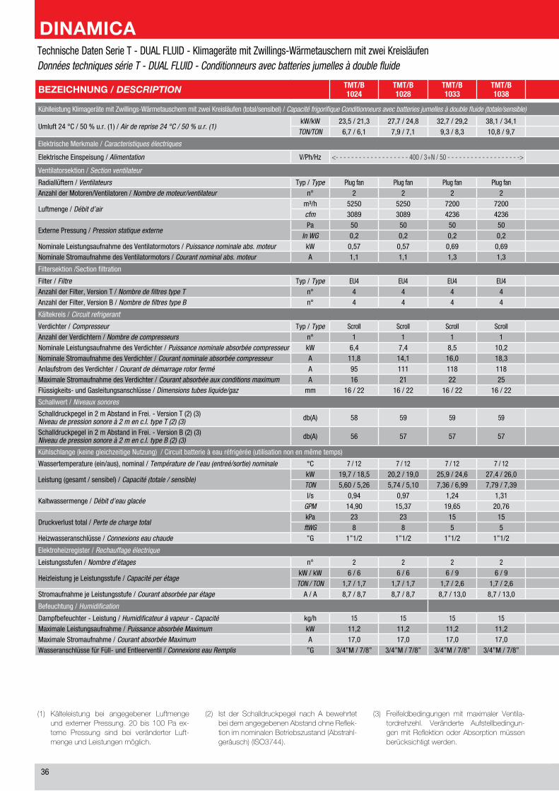
��
(1) Kälteleistung bei angegebener LuftmengeundexternerPressung. 20bis 100Pa ex-terne Pressung sind bei veränderter Luft-mengeundLeistungenmöglich.
(2) Ist der Schalldruckpegel nach A bewehrtetbeidemangegebenenAbstandohneReflek-tionimnominalenBetriebszustand(Abstrahl-geräusch)(ISO3744).
(3) Freifeldbedingungen mit maximaler Ventila-tordrehzehl. Veränderte Aufstellbedingun-genmitReflektionoderAbsorptionmüssenberücksichtigtwerden.
BEZEICHNUNG / DESCRIPTION TMT/B1024
TMT/B1028
TMT/B1033
TMT/B1038
TMT/B1049
TMT/B1062
TMT/B2029
TMT/B2038
TMT/B2049
TMT/B2058
TMT/B2069
TMT/B2078
TLT/B2096
TLT/B2125
Kühlleistung Klimageräte mit Zwillings-Wärmetauschern mit zwei Kreisläufen (total/sensibel) / Capacité frigorifique Conditionneurs avec batteries jumelles à double fluide (totale/sensible)
Umluft �� °C / �0 % u.r. (1) / Air de reprise 24 °C / 50 % u.r. (1)kW/kW ��,� / �1,� ��,� / ��,� ��,� / ��,� ��,1 / ��,1 ��,0 / ��,� �1,� / ��,0 ��,� / ��,1 ��,� / ��,1 ��,� / ��,� ��,0 / ��,0 ��,1 / ��,1 ��,� / ��,1 ��,� / ��,� 1��,1 / 1��,1
TON/TON �,� / �,1 �,� / �,1 �,� / �,� 10,� / �,� 1�,� / 1�,� 1�,� / 1�,� �,1 / �,0 10,� / 10,� 1�,0 / 1�,0 1�,� / 1�,� 1�,� / 1�,� ��,0 / �1,� ��,� / ��,� ��,� / ��,�
Elektrische Merkmale / Caracteristiques électriques
Elektrische Einspeisung / Alimentation V/Ph/Hz <- - - - - - - - - - - - - - - - - - - �00 / �+N / �0 - - - - - - - - - - - - - - - - - - -> <- - - - - - - - - - - - - - - - - - - - - - - - - - - - - - - - - - - - - - �00 / �+N / �0 - - - - - - - - - - - - - - - - - - - - - - - - - - - - - - - - - - - - - ->
Ventilatorsektion / Section ventilateur
Radiallüftern / Ventilateurs Typ / Type Plug fan Plug fan Plug fan Plug fan Plug fan Plug fan Plug fan Plug fan Plug fan Plug fan Plug fan Plug fan Plug fan Plug fanAnzahl der Motoren/Ventilatoren / Nombre de moteur/ventilateur n° � � � � � � � � � � � � � �
Luftmenge / Débit d’airm³/h ���0 ���0 ��00 ��00 10�00 11��0 ���0 ��00 10�00 11��0 1��00 1��00 1�000 ��000cfm �0�� �0�� ���� ���� �001 ��1� �0�� ���� �001 ��1� ���� ���� 10��0 1�1�0
Externe Pressung / Pression statique externePa �0 �0 �0 �0 �0 �0 �0 �0 �0 �0 �0 �0 �0 �0
In WG 0,� 0,� 0,� 0,� 0,� 0,� 0,� 0,� 0,� 0,� 0,� 0,� 0,� 0,�Nominale Leistungsaufnahme des Ventilatormotors / Puissance nominale abs. moteur kW 0,�� 0,�� 0,�� 0,�� 0,�� 0,�� 0,�� 0,�� 0,�� 0,�� 0,�� 0,�� 0,�� 0,��Nominale Stromaufnahme des Ventilatormotors / Courant nominal abs. moteur A 1,1 1,1 1,� 1,� 1,� 1,� 1,1 1,� 1,� 1,� 1,� 1,� 1,� 1,�
Filtersektion /Section filtration
Filter / Filtre Typ / Type EU� EU� EU� EU� EU� EU� EU� EU� EU� EU� EU� EU� EU� EU�Anzahl der Filter, Version T / Nombre de filtres type T n° � � � � � � � � � � � � � 10Anzahl der Filter, Version B / Nombre de filtres type B n° � � � � � � � � � � � � 10 10
Kältekreis / Circuit refrigerant
Verdichter / Compresseur Typ / Type Scroll Scroll Scroll Scroll Scroll Scroll Scroll Scroll Scroll Scroll Scroll Scroll Scroll ScrollAnzahl der Verdichtern / Nombre de compresseurs n° 1 1 1 1 1 1 � � � � � � � �Nominale Leistungsaufnahme des Verdichter / Puissance nominale absorbée compresseur kW �,� �,� �,� 10,� 1�,� 1�,� �,0 �,� �,� �,� �,� 10,0 1�,� 1�,�Nominale Stromaufnahme des Verdichter / Courant nominale absorbée compresseur A 11,� 1�,1 1�,0 1�,� ��,0 ��,� �,� �,� 1�,1 1�,� 1�,� 1�,0 ��,� ��,�Anlaufstrom des Verdichter / Courant de démarrage rotor fermé A �� 111 11� 11� 1�� ��� �1 �� �� 111 11� 11� 1�� ���Maximale Stromaufnahme des Verdichter / Courant absorbée aux conditions maximum A 1� �1 �� �� �� �0 10 1� 1� �1 �� �� �� �0Flüssigkeits- und Gasleitungsanschlüsse / Dimensions tubes liquide/gaz mm 1� / �� 1� / �� 1� / �� 1� / �� �� / �� �� / �� �x1� / �x1� �x1� / �x1� �x1� / �x1� �x1� / �x�� �x1� / �x�� �x1� / �x�� �x�� / �x�� �x�� / �x��
Schallwert / Niveaux sonores
Schalldruckpegel in � m Abstand in Frei. - Version T (�) (�)Niveau de pression sonore à 2 m en c.l. type T (2) (3) db(A) �� �� �� �� �� �� �� �� �0 �� �� �� �� �0
Schalldruckpegel in � m Abstand in Frei. - Version B (�) (�)Niveau de pression sonore à 2 m en c.l. type B (2) (3) db(A) �� �� �� �� �0 �0 �� �� �� �0 �0 �0 �� ��
Kühlschlange (keine gleichzeitige Nutzung) / Circuit batterie à eau réfrigérée (utilisation non en même temps)
Wassertemperature (ein/aus), nominal / Température de l’eau (entreé/sortie) nominale °C � / 1� � / 1� � / 1� � / 1� � / 1� � / 1� � / 1� � / 1� � / 1� � / 1� � / 1� � / 1� � / 1� � / 1�
Leistung (gesamt / sensibel) / Capacité (totale / sensible)kW 1�,� / 1�,� �0,� / 1�,0 ��,� / ��,� ��,� / ��,0 �0,� / ��,� ��,� / ��,� �0,� / 1�,0 ��,� / ��,� �0,� / ��,� ��,� / ��,� ��,0 / ��,� ��,0 / �0,� ��,1 / �0,� ��,1 / ��,�TON �,�0 / �,�� �,�� / �,10 �,�� / �,�� �,�� / �,�� 11,�0 / 10,�� 1�,�� / 1�,�0 �,�� / �,�0 �,�� / �,�� 11,�0 / 10,�� 1�,�� / 1�,�� 1�,�� / 1�,0� 1�,0� / 1�,�� 1�,�� / 1�,�� ��,0� / ��,��
Kaltwassermenge / Débit d’eau glacéel/s 0,�� 0,�� 1,�� 1,�1 1,�� �,�� 0,�� 1,�� 1,�� �,�1 �,�� �,�� �,0� �,�1
GPM 1�,�0 1�,�� 1�,�� �0,�� �0,�1 ��,�� 1�,�� 1�,�1 �0,�1 ��,�1 ��,�1 �0,10 ��,�0 ��,��
Druckverlust total / Perte de charge totalkPa �� �� 1� 1� �1 �1 �� 1� �1 �1 1� 1� �0 ��ftWG � � � � 1� �0 � � 1� �0 � � 10 10
Heizwasseranschlüsse / Connexions eau chaude ”G 1”1/� 1”1/� 1”1/� 1”1/� �” �” 1”1/� 1”1/� �” �” �” �” �” �”1/�
Elektroheizregister / Rechauffage électrique
Leistungsstufen / Nombre d’étages n° � � � � � � � � � � � � � �
Heizleistung je Leistungsstufe / Capacité per étagekW / kW � / � � / � � / � � / � � / � � / � � / � � / � � / � � / � 1� / 1� 1� / 1� 1� / 1� 1� / 1�
TON / TON 1,� / 1,� 1,� / 1,� 1,� / �,� 1,� / �,� 1,� / �,� 1,� / �,� 1,� / �,� 1,� / �,� 1,� / �,� 1,� / �,� �,� / �,� �,� / �,� �,� / �,� �,� / �,�Stromaufnahme je Leistungsstufe / Courant absorbée par étage A / A �,� / �,� �,� / �,� �,� / 1�,0 �,� / 1�,0 �,� / 1�,0 �,� / 1�,0 �,� / 1�,0 �,� / 1�,0 �,� / 1�,0 �,� / 1�,0 1�,1 / 1�,1 1�,1 / 1�,1 1�,1 / 1�,1 1�,1 / 1�,1
Befeuchtung / Humidification
Dampfbefeuchter - Leistung / Humidificateur à vapeur - Capacité kg/h 1� 1� 1� 1� 1� 1� 1� 1� 1� 1� 1� 1� 1� 1�Maximale Leistungsaufnahme / Puissance absorbée Maximum kW 11,� 11,� 11,� 11,� 11,� 11,� 11,� 11,� 11,� 11,� 11,� 11,� 11,� 11,�Maximale Stromaufnahme / Courant absorbée Maximum A 1�,0 1�,0 1�,0 1�,0 1�,0 1�,0 1�,0 1�,0 1�,0 1�,0 1�,0 1�,0 1�,0 1�,0Wasseranschlüsse für Füll- und Entleerventil / Connexions eau Remplis ”G �/�”M / �/�” �/�”M / �/�” �/�”M / �/�” �/�”M / �/�” �/�”M / �/�” �/�”M / �/�” �/�”M / �/�” �/�”M / �/�” �/�”M / �/�” �/�”M / �/�” �/�”M / �/�” �/�”M / �/�” �/�”M / �/�” �/�”M / �/�”
Technische Daten Serie T - DUAL FLUID - Klimageräte mit Zwillings-Wärmetauschern mit zwei KreisläufenDonnées techniques série T - DUAL FLUID - Conditionneurs avec batteries jumelles à double fluide
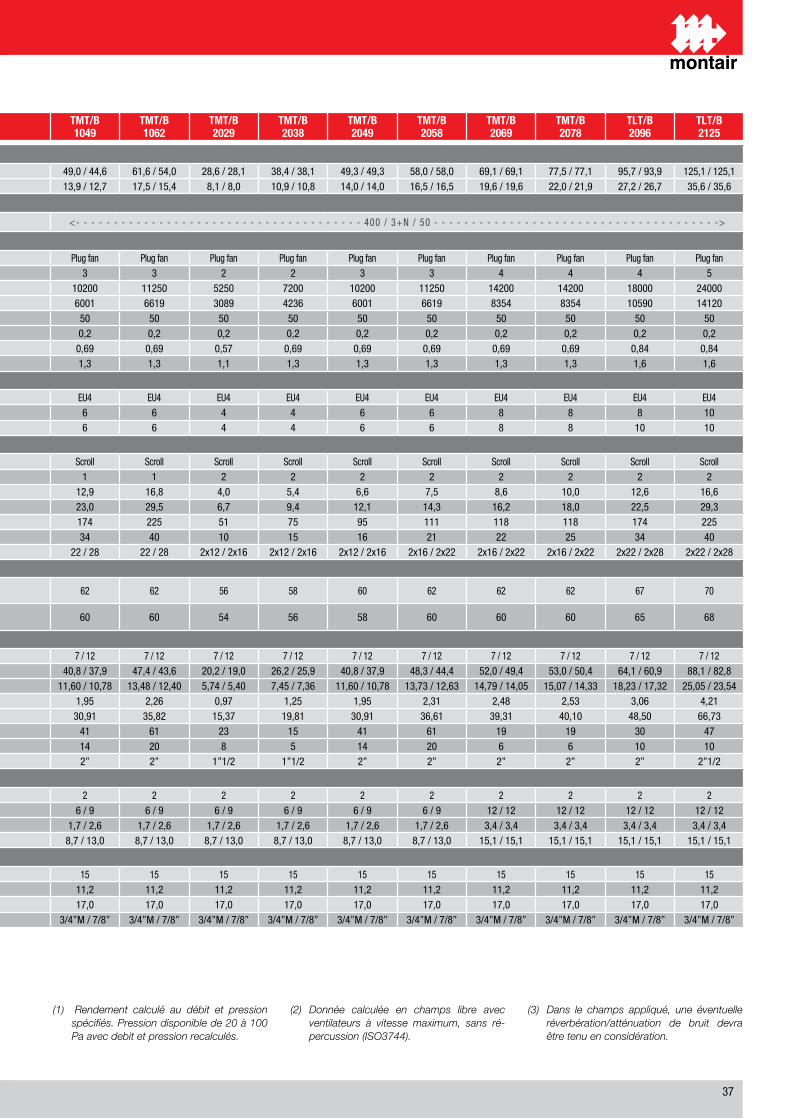
��
(1) Rendement calculé au débit et pression spécifiés. Pression disponible de 20 à 100 Pa avec debit et pression recalculés.
(2) Donnée calculée en champs libre avec ventilateurs à vitesse maximum, sans ré-percussion (ISO3744).
(3) Dans le champs appliqué, une éventuelle réverbération/atténuation de bruit devra être tenu en considération.
BEZEICHNUNG / DESCRIPTION TMT/B1024
TMT/B1028
TMT/B1033
TMT/B1038
TMT/B1049
TMT/B1062
TMT/B2029
TMT/B2038
TMT/B2049
TMT/B2058
TMT/B2069
TMT/B2078
TLT/B2096
TLT/B2125
Kühlleistung Klimageräte mit Zwillings-Wärmetauschern mit zwei Kreisläufen (total/sensibel) / Capacité frigorifique Conditionneurs avec batteries jumelles à double fluide (totale/sensible)
Umluft �� °C / �0 % u.r. (1) / Air de reprise 24 °C / 50 % u.r. (1)kW/kW ��,� / �1,� ��,� / ��,� ��,� / ��,� ��,1 / ��,1 ��,0 / ��,� �1,� / ��,0 ��,� / ��,1 ��,� / ��,1 ��,� / ��,� ��,0 / ��,0 ��,1 / ��,1 ��,� / ��,1 ��,� / ��,� 1��,1 / 1��,1
TON/TON �,� / �,1 �,� / �,1 �,� / �,� 10,� / �,� 1�,� / 1�,� 1�,� / 1�,� �,1 / �,0 10,� / 10,� 1�,0 / 1�,0 1�,� / 1�,� 1�,� / 1�,� ��,0 / �1,� ��,� / ��,� ��,� / ��,�
Elektrische Merkmale / Caracteristiques électriques
Elektrische Einspeisung / Alimentation V/Ph/Hz <- - - - - - - - - - - - - - - - - - - �00 / �+N / �0 - - - - - - - - - - - - - - - - - - -> <- - - - - - - - - - - - - - - - - - - - - - - - - - - - - - - - - - - - - - �00 / �+N / �0 - - - - - - - - - - - - - - - - - - - - - - - - - - - - - - - - - - - - - ->
Ventilatorsektion / Section ventilateur
Radiallüftern / Ventilateurs Typ / Type Plug fan Plug fan Plug fan Plug fan Plug fan Plug fan Plug fan Plug fan Plug fan Plug fan Plug fan Plug fan Plug fan Plug fanAnzahl der Motoren/Ventilatoren / Nombre de moteur/ventilateur n° � � � � � � � � � � � � � �
Luftmenge / Débit d’airm³/h ���0 ���0 ��00 ��00 10�00 11��0 ���0 ��00 10�00 11��0 1��00 1��00 1�000 ��000cfm �0�� �0�� ���� ���� �001 ��1� �0�� ���� �001 ��1� ���� ���� 10��0 1�1�0
Externe Pressung / Pression statique externePa �0 �0 �0 �0 �0 �0 �0 �0 �0 �0 �0 �0 �0 �0
In WG 0,� 0,� 0,� 0,� 0,� 0,� 0,� 0,� 0,� 0,� 0,� 0,� 0,� 0,�Nominale Leistungsaufnahme des Ventilatormotors / Puissance nominale abs. moteur kW 0,�� 0,�� 0,�� 0,�� 0,�� 0,�� 0,�� 0,�� 0,�� 0,�� 0,�� 0,�� 0,�� 0,��Nominale Stromaufnahme des Ventilatormotors / Courant nominal abs. moteur A 1,1 1,1 1,� 1,� 1,� 1,� 1,1 1,� 1,� 1,� 1,� 1,� 1,� 1,�
Filtersektion /Section filtration
Filter / Filtre Typ / Type EU� EU� EU� EU� EU� EU� EU� EU� EU� EU� EU� EU� EU� EU�Anzahl der Filter, Version T / Nombre de filtres type T n° � � � � � � � � � � � � � 10Anzahl der Filter, Version B / Nombre de filtres type B n° � � � � � � � � � � � � 10 10
Kältekreis / Circuit refrigerant
Verdichter / Compresseur Typ / Type Scroll Scroll Scroll Scroll Scroll Scroll Scroll Scroll Scroll Scroll Scroll Scroll Scroll ScrollAnzahl der Verdichtern / Nombre de compresseurs n° 1 1 1 1 1 1 � � � � � � � �Nominale Leistungsaufnahme des Verdichter / Puissance nominale absorbée compresseur kW �,� �,� �,� 10,� 1�,� 1�,� �,0 �,� �,� �,� �,� 10,0 1�,� 1�,�Nominale Stromaufnahme des Verdichter / Courant nominale absorbée compresseur A 11,� 1�,1 1�,0 1�,� ��,0 ��,� �,� �,� 1�,1 1�,� 1�,� 1�,0 ��,� ��,�Anlaufstrom des Verdichter / Courant de démarrage rotor fermé A �� 111 11� 11� 1�� ��� �1 �� �� 111 11� 11� 1�� ���Maximale Stromaufnahme des Verdichter / Courant absorbée aux conditions maximum A 1� �1 �� �� �� �0 10 1� 1� �1 �� �� �� �0Flüssigkeits- und Gasleitungsanschlüsse / Dimensions tubes liquide/gaz mm 1� / �� 1� / �� 1� / �� 1� / �� �� / �� �� / �� �x1� / �x1� �x1� / �x1� �x1� / �x1� �x1� / �x�� �x1� / �x�� �x1� / �x�� �x�� / �x�� �x�� / �x��
Schallwert / Niveaux sonores
Schalldruckpegel in � m Abstand in Frei. - Version T (�) (�)Niveau de pression sonore à 2 m en c.l. type T (2) (3) db(A) �� �� �� �� �� �� �� �� �0 �� �� �� �� �0
Schalldruckpegel in � m Abstand in Frei. - Version B (�) (�)Niveau de pression sonore à 2 m en c.l. type B (2) (3) db(A) �� �� �� �� �0 �0 �� �� �� �0 �0 �0 �� ��
Kühlschlange (keine gleichzeitige Nutzung) / Circuit batterie à eau réfrigérée (utilisation non en même temps)
Wassertemperature (ein/aus), nominal / Température de l’eau (entreé/sortie) nominale °C � / 1� � / 1� � / 1� � / 1� � / 1� � / 1� � / 1� � / 1� � / 1� � / 1� � / 1� � / 1� � / 1� � / 1�
Leistung (gesamt / sensibel) / Capacité (totale / sensible)kW 1�,� / 1�,� �0,� / 1�,0 ��,� / ��,� ��,� / ��,0 �0,� / ��,� ��,� / ��,� �0,� / 1�,0 ��,� / ��,� �0,� / ��,� ��,� / ��,� ��,0 / ��,� ��,0 / �0,� ��,1 / �0,� ��,1 / ��,�TON �,�0 / �,�� �,�� / �,10 �,�� / �,�� �,�� / �,�� 11,�0 / 10,�� 1�,�� / 1�,�0 �,�� / �,�0 �,�� / �,�� 11,�0 / 10,�� 1�,�� / 1�,�� 1�,�� / 1�,0� 1�,0� / 1�,�� 1�,�� / 1�,�� ��,0� / ��,��
Kaltwassermenge / Débit d’eau glacéel/s 0,�� 0,�� 1,�� 1,�1 1,�� �,�� 0,�� 1,�� 1,�� �,�1 �,�� �,�� �,0� �,�1
GPM 1�,�0 1�,�� 1�,�� �0,�� �0,�1 ��,�� 1�,�� 1�,�1 �0,�1 ��,�1 ��,�1 �0,10 ��,�0 ��,��
Druckverlust total / Perte de charge totalkPa �� �� 1� 1� �1 �1 �� 1� �1 �1 1� 1� �0 ��ftWG � � � � 1� �0 � � 1� �0 � � 10 10
Heizwasseranschlüsse / Connexions eau chaude ”G 1”1/� 1”1/� 1”1/� 1”1/� �” �” 1”1/� 1”1/� �” �” �” �” �” �”1/�
Elektroheizregister / Rechauffage électrique
Leistungsstufen / Nombre d’étages n° � � � � � � � � � � � � � �
Heizleistung je Leistungsstufe / Capacité per étagekW / kW � / � � / � � / � � / � � / � � / � � / � � / � � / � � / � 1� / 1� 1� / 1� 1� / 1� 1� / 1�
TON / TON 1,� / 1,� 1,� / 1,� 1,� / �,� 1,� / �,� 1,� / �,� 1,� / �,� 1,� / �,� 1,� / �,� 1,� / �,� 1,� / �,� �,� / �,� �,� / �,� �,� / �,� �,� / �,�Stromaufnahme je Leistungsstufe / Courant absorbée par étage A / A �,� / �,� �,� / �,� �,� / 1�,0 �,� / 1�,0 �,� / 1�,0 �,� / 1�,0 �,� / 1�,0 �,� / 1�,0 �,� / 1�,0 �,� / 1�,0 1�,1 / 1�,1 1�,1 / 1�,1 1�,1 / 1�,1 1�,1 / 1�,1
Befeuchtung / Humidification
Dampfbefeuchter - Leistung / Humidificateur à vapeur - Capacité kg/h 1� 1� 1� 1� 1� 1� 1� 1� 1� 1� 1� 1� 1� 1�Maximale Leistungsaufnahme / Puissance absorbée Maximum kW 11,� 11,� 11,� 11,� 11,� 11,� 11,� 11,� 11,� 11,� 11,� 11,� 11,� 11,�Maximale Stromaufnahme / Courant absorbée Maximum A 1�,0 1�,0 1�,0 1�,0 1�,0 1�,0 1�,0 1�,0 1�,0 1�,0 1�,0 1�,0 1�,0 1�,0Wasseranschlüsse für Füll- und Entleerventil / Connexions eau Remplis ”G �/�”M / �/�” �/�”M / �/�” �/�”M / �/�” �/�”M / �/�” �/�”M / �/�” �/�”M / �/�” �/�”M / �/�” �/�”M / �/�” �/�”M / �/�” �/�”M / �/�” �/�”M / �/�” �/�”M / �/�” �/�”M / �/�” �/�”M / �/�”
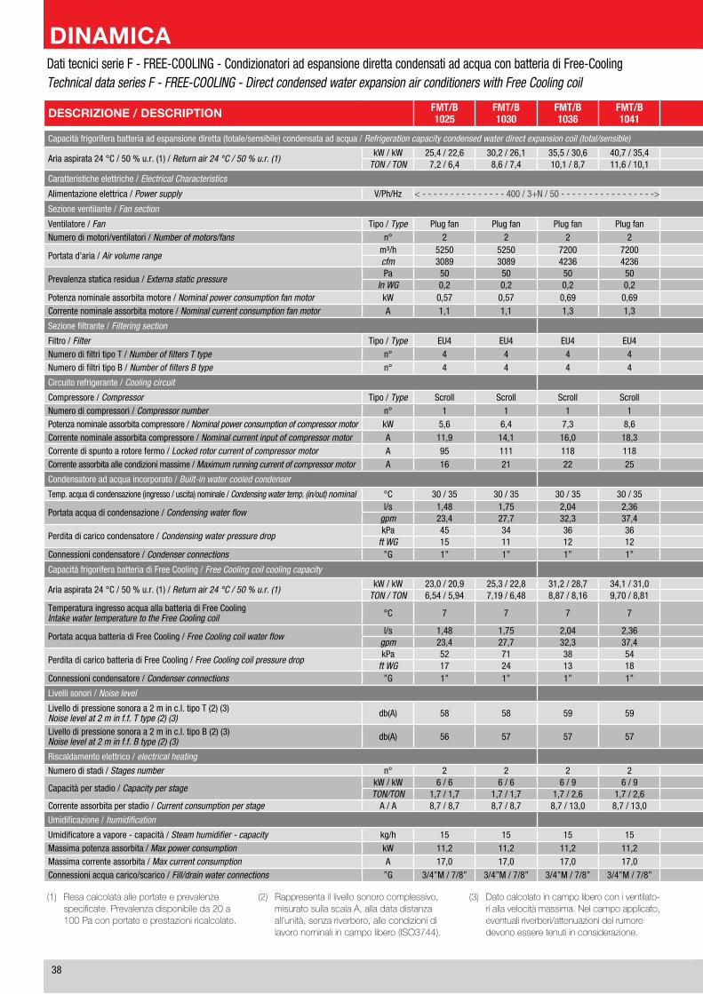
��
(1) Resacalcolataalleportateeprevalenze specificate.Prevalenzadisponibileda20a 100Paconportateeprestazioniricalcolate.
(2) Rappresentaililvellosonorocomplessivo,misuratosullascalaA,alladatadistanzaall’unità,senzariverbero,allecondizionidilavoronominaliincampolibero(ISO3744).
(3) Datocalcolatoincampoliberoconiventilato-riallavelocitàmassima.Nelcampoapplicato,eventualiriverberi/attenuazionidelrumoredevonoesseretenutiinconsiderazione.
DESCRIZIONE / DESCRIPTION FMT/B1025
FMT/B1030
FMT/B1036
FMT/B1041
FMT/B1053
FMT/B1066
FMT/B2031
FMT/B2041
FMT/B2055
FMT/B2064
FMT/B2074
FMT/B2083
FLT/B2104
FLT/B2134
Capacità frigorifera batteria ad espansione diretta (totale/sensibile) condensata ad acqua / Refrigeration capacity condensed water direct expansion coil (total/sensible)
Aria aspirata �� °C / �0 % u.r. (1) / Return air 24 °C / 50 % u.r. (1)kW / kW ��,� / ��,� �0,� / ��,1 ��,� / �0,� �0,� / ��,� ��,� / ��,1 ��,1 / ��,� �1,� / �0,� �1,� / �1,1 ��,� / ��,0 ��,� / ��,� ��,�/ ��,0 ��,� / ��,� 10�,0 / 10�,0 1��,� / 1��,�
TON / TON �,� / �,� �,� / �,� 10,1 / �,� 11,� / 10,1 1�,0 / 1�,1 1�,� / 1�,1 �,� / �,� 11,� / 11,� 1�,� / 1�,� 1�,� / 1�,0 �1,0 / �1,0 ��,� / ��,� ��,� / ��,� ��,0 / ��,0
Caratteristiche elettriche / Electrical Characteristics
Alimentazione elettrica / Power supply V/Ph/Hz < - - - - - - - - - - - - - - - �00 / �+N / �0 - - - - - - - - - - - - - - - - -> < - - - - - - - - - - - - - - - - - - - - - - - - - - - - - - - - - - - - - - - - - - - - - �00 / �+N / �0 - - - - - - - - - - - - - - - - - - - - - - - - - - - - - - - - - - - - - - - - - - - - - - ->
Sezione ventilante / Fan section
Ventilatore / Fan Tipo / Type Plug fan Plug fan Plug fan Plug fan Plug fan Plug fan Plug fan Plug fan Plug fan Plug fan Plug fan Plug fan Plug fan Plug fanNumero di motori/ventilatori / Number of motors/fans n° � � � � � � � � � � � � � �
Portata d’aria / Air volume rangem³/h ���0 ���0 ��00 ��00 10�00 11��0 ���0 ��00 10�00 11��0 1��00 1��00 1�000 ��000cfm �0�� �0�� ���� ���� �001 ��1� �0�� ���� �001 ��1� ���� ���� 10��0 1�1�0
Prevalenza statica residua / Externa static pressurePa �0 �0 �0 �0 �0 �0 �0 �0 �0 �0 �0 �0 �0 �0
In WG 0,� 0,� 0,� 0,� 0,� 0,� 0,� 0,� 0,� 0,� 0,� 0,� 0,� 0,�Potenza nominale assorbita motore / Nominal power consumption fan motor kW 0,�� 0,�� 0,�� 0,�� 0,�� 0,�� 0,�� 0,�� 0,�� 0,�� 0,�� 0,�� 0,�� 0,��Corrente nominale assorbita motore / Nominal current consumption fan motor A 1,1 1,1 1,� 1,� 1,� 1,� 1,1 1,� 1,� 1,� 1,� 1,� 1,� 1,�
Sezione filtrante / Filtering section
Filtro / Filter Tipo / Type EU� EU� EU� EU� EU� EU� EU� EU� EU� EU� EU� EU� EU� EU�Numero di filtri tipo T / Number of filters T type n° � � � � � � � � � � � � � 10Numero di filtri tipo B / Number of filters B type n° � � � � � � � � � � � � 10 10
Circuito refrigerante / Cooling circuit
Compressore / Compressor Tipo / Type Scroll Scroll Scroll Scroll Scroll Scroll Scroll Scroll Scroll Scroll Scroll Scroll Scroll ScrollNumero di compressori / Compressor number n° 1 1 1 1 1 1 � � � � � � � �Potenza nominale assorbita compressore / Nominal power consumption of compressor motor kW �,� �,� �,� �,� 11,� 1�,� �,� �,� �,� �,� �,� �,� 11,� 1�,�Corrente nominale assorbita compressore / Nominal current input of compressor motor A 11,� 1�,1 1�,0 1�,� ��,1 ��,� �,� �,� 1�,� 1�,� 1�,� 1�,0 ��,� ��,�Corrente di spunto a rotore fermo / Locked rotor current of compressor motor A �� 111 11� 11� 1�� ��� �1 �� �� 111 11� 11� 1�� ���Corrente assorbita alle condizioni massime / Maximum running current of compressor motor A 1� �1 �� �� �� �0 10 1� 1� �1 �� �� �� �0
Condensatore ad acqua incorporato / Built-in water cooled condenser
Temp. acqua di condensazione (ingresso / uscita) nominale / Condensing water temp. (in/out) nominal °C �0 / �� �0 / �� �0 / �� �0 / �� �0 / �� �0 / �� �0 / �� �0 / �� �0 / �� �0 / �� �0 / �� �0 / �� �0 / �� �0 / ��
Portata acqua di condensazione / Condensing water flowl/s 1,�� 1,�� �,0� �,�� �,0� �,�� 1,�� �,1� �,�� �,�� �,�� �,�� �,�0 �,0�
gpm ��,� ��,� ��,� ��,� ��,� �1,1 ��,1 ��,� ��,� ��,� �1,� ��,1 ��,1 11�,�
Perdita di carico condensatore / Condensing water pressure dropkPa �� �� �� �� �� �� �1 �0 �� �� �� �� �1 ��
ft WG 1� 11 1� 1� 1� 1� 10 1� 1� 1� 1� 1� 1� 1�Connessioni condensatore / Condenser connections ”G 1” 1” 1” 1” 1” 1”1/� � x 1” � x 1” � x 1” � x 1” � x 1” � x 1” � x 1” � x 1”1/�
Capacità frigorifera batteria di Free Cooling / Free Cooling coil cooling capacity
Aria aspirata �� °C / �0 % u.r. (1) / Return air 24 °C / 50 % u.r. (1)kW / kW ��,0 / �0,� ��,� / ��,� �1,� / ��,� ��,1 / �1,0 ��,1 / ��,� �1,� / ��,0 ��,� / ��,� ��,� / ��,� ��,� / ��,� �0,� / ��,� ��,� / ��,� ��,� / �0,0 ��,0 / ��,� 10� / ��,�
TON / TON �,�� / �,�� �,1� / �,�� �,�� / �,1� �,�0 / �,�1 1�,�� / 1�,00 1�,�0 / 1�,0� �,�� / �,�1 �,�0 / �,�� 1�,1� / 1�,0� 1�,�0 / 1�,1� 1�,�� / 1�,�� 1�,�� / 1�,0� ��,�� / �0,�� ��,�� / ��,��Temperatura ingresso acqua alla batteria di Free CoolingIntake water temperature to the Free Cooling coil °C � � � � � � � � � � � � � �
Portata acqua batteria di Free Cooling / Free Cooling coil water flowl/s 1,�� 1,�� �,0� �,�� �,0� �,�� 1,�� �,1� �,�� �,�� �,�� �,�� �,�0 �,0�
gpm ��,� ��,� ��,� ��,� ��,� �1,1 ��,1 ��,� ��,� ��,� �1,� ��,1 ��,1 11�,�
Perdita di carico batteria di Free Cooling / Free Cooling coil pressure dropkPa �� �1 �� �� �� �� �� �� �� �1 �� �� �� 11�
ft WG 1� �� 1� 1� � 1� �1 1� � � 1� �1 �� ��Connessioni condensatore / Condenser connections ”G 1” 1” 1” 1” 1” 1”1/� � x 1” � x 1” � x 1” � x 1” � x 1” � x 1” � x 1” � x 1”1/�
Livelli sonori / Noise level
Livello di pressione sonora a � m in c.l. tipo T (�) (�)Noise level at 2 m in f.f. T type (2) (3) db(A) �� �� �� �� �� �� �� �� �0 �� �� �� �� �0
Livello di pressione sonora a � m in c.l. tipo B (�) (�)Noise level at 2 m in f.f. B type (2) (3) db(A) �� �� �� �� �0 �0 �� �� �� �0 �0 �0 �� ��
Riscaldamento elettrico / electrical heating
Numero di stadi / Stages number n° � � � � � � � � � � � � � �
Capacità per stadio / Capacity per stagekW / kW � / � � / � � / � � / � � / � � / � � / � � / � � / � � / � 1� / 1� 1� / 1� 1� / 1� 1� / 1�TON/TON 1,� / 1,� 1,� / 1,� 1,� / �,� 1,� / �,� 1,� / �,� 1,� / �,� 1,� / �,� 1,� / �,� 1,� / �,� 1,� / �,� �,� / �,� �,� / �,� �,� / �,� �,� / �,�
Corrente assorbita per stadio / Current consumption per stage A / A �,� / �,� �,� / �,� �,� / 1�,0 �,� / 1�,0 �,� / 1�,0 �,� / 1�,0 �,� / 1�,0 �,� / 1�,0 �,� / 1�,0 �,� / 1�,0 1�,1 / 1�,1 1�,1 / 1�,1 1�,1 / 1�,1 1�,1 / 1�,1
Umidificazione / humidification
Umidificatore a vapore - capacità / Steam humidifier - capacity kg/h 1� 1� 1� 1� 1� 1� 1� 1� 1� 1� 1� 1� 1� 1�Massima potenza assorbita / Max power consumption kW 11,� 11,� 11,� 11,� 11,� 11,� 11,� 11,� 11,� 11,� 11,� 11,� 11,� 11,�Massima corrente assorbita / Max current consumption A 1�,0 1�,0 1�,0 1�,0 1�,0 1�,0 1�,0 1�,0 1�,0 1�,0 1�,0 1�,0 1�,0 1�,0Connessioni acqua carico/scarico / Fill/drain water connections ”G �/�”M / �/�” �/�”M / �/�” �/�”M / �/�” �/�”M / �/�” �/�”M / �/�” �/�”M / �/�” �/�”M / �/�” �/�”M / �/�” �/�”M / �/�” �/�”M / �/�” �/�”M / �/�” �/�”M / �/�” �/�”M / �/�” �/�”M / �/�”
Dati tecnici serie F - FREE-COOLING - Condizionatori ad espansione diretta condensati ad acqua con batteria di Free-CoolingTechnical data series F - FREE-COOLING - Direct condensed water expansion air conditioners with Free Cooling coil
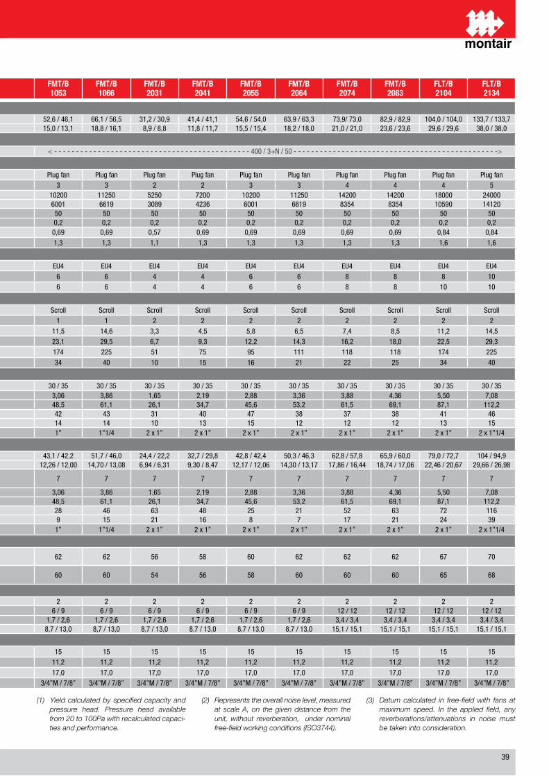
��
(1) Yield calculated by specified capacity and pressure head. Pressure head available from 20 to 100Pa with recalculated capaci-ties and performance.
(2) Represents the overall noise level, measured at scale A, on the given distance from the unit, without reverberation, under nominal free-field working conditions (ISO3744).
(3) Datum calculated in free-field with fans at maximum speed. In the applied field, any reverberations/attenuations in noise must be taken into consideration.
DESCRIZIONE / DESCRIPTION FMT/B1025
FMT/B1030
FMT/B1036
FMT/B1041
FMT/B1053
FMT/B1066
FMT/B2031
FMT/B2041
FMT/B2055
FMT/B2064
FMT/B2074
FMT/B2083
FLT/B2104
FLT/B2134
Capacità frigorifera batteria ad espansione diretta (totale/sensibile) condensata ad acqua / Refrigeration capacity condensed water direct expansion coil (total/sensible)
Aria aspirata �� °C / �0 % u.r. (1) / Return air 24 °C / 50 % u.r. (1)kW / kW ��,� / ��,� �0,� / ��,1 ��,� / �0,� �0,� / ��,� ��,� / ��,1 ��,1 / ��,� �1,� / �0,� �1,� / �1,1 ��,� / ��,0 ��,� / ��,� ��,�/ ��,0 ��,� / ��,� 10�,0 / 10�,0 1��,� / 1��,�
TON / TON �,� / �,� �,� / �,� 10,1 / �,� 11,� / 10,1 1�,0 / 1�,1 1�,� / 1�,1 �,� / �,� 11,� / 11,� 1�,� / 1�,� 1�,� / 1�,0 �1,0 / �1,0 ��,� / ��,� ��,� / ��,� ��,0 / ��,0
Caratteristiche elettriche / Electrical Characteristics
Alimentazione elettrica / Power supply V/Ph/Hz < - - - - - - - - - - - - - - - �00 / �+N / �0 - - - - - - - - - - - - - - - - -> < - - - - - - - - - - - - - - - - - - - - - - - - - - - - - - - - - - - - - - - - - - - - - �00 / �+N / �0 - - - - - - - - - - - - - - - - - - - - - - - - - - - - - - - - - - - - - - - - - - - - - - ->
Sezione ventilante / Fan section
Ventilatore / Fan Tipo / Type Plug fan Plug fan Plug fan Plug fan Plug fan Plug fan Plug fan Plug fan Plug fan Plug fan Plug fan Plug fan Plug fan Plug fanNumero di motori/ventilatori / Number of motors/fans n° � � � � � � � � � � � � � �
Portata d’aria / Air volume rangem³/h ���0 ���0 ��00 ��00 10�00 11��0 ���0 ��00 10�00 11��0 1��00 1��00 1�000 ��000cfm �0�� �0�� ���� ���� �001 ��1� �0�� ���� �001 ��1� ���� ���� 10��0 1�1�0
Prevalenza statica residua / Externa static pressurePa �0 �0 �0 �0 �0 �0 �0 �0 �0 �0 �0 �0 �0 �0
In WG 0,� 0,� 0,� 0,� 0,� 0,� 0,� 0,� 0,� 0,� 0,� 0,� 0,� 0,�Potenza nominale assorbita motore / Nominal power consumption fan motor kW 0,�� 0,�� 0,�� 0,�� 0,�� 0,�� 0,�� 0,�� 0,�� 0,�� 0,�� 0,�� 0,�� 0,��Corrente nominale assorbita motore / Nominal current consumption fan motor A 1,1 1,1 1,� 1,� 1,� 1,� 1,1 1,� 1,� 1,� 1,� 1,� 1,� 1,�
Sezione filtrante / Filtering section
Filtro / Filter Tipo / Type EU� EU� EU� EU� EU� EU� EU� EU� EU� EU� EU� EU� EU� EU�Numero di filtri tipo T / Number of filters T type n° � � � � � � � � � � � � � 10Numero di filtri tipo B / Number of filters B type n° � � � � � � � � � � � � 10 10
Circuito refrigerante / Cooling circuit
Compressore / Compressor Tipo / Type Scroll Scroll Scroll Scroll Scroll Scroll Scroll Scroll Scroll Scroll Scroll Scroll Scroll ScrollNumero di compressori / Compressor number n° 1 1 1 1 1 1 � � � � � � � �Potenza nominale assorbita compressore / Nominal power consumption of compressor motor kW �,� �,� �,� �,� 11,� 1�,� �,� �,� �,� �,� �,� �,� 11,� 1�,�Corrente nominale assorbita compressore / Nominal current input of compressor motor A 11,� 1�,1 1�,0 1�,� ��,1 ��,� �,� �,� 1�,� 1�,� 1�,� 1�,0 ��,� ��,�Corrente di spunto a rotore fermo / Locked rotor current of compressor motor A �� 111 11� 11� 1�� ��� �1 �� �� 111 11� 11� 1�� ���Corrente assorbita alle condizioni massime / Maximum running current of compressor motor A 1� �1 �� �� �� �0 10 1� 1� �1 �� �� �� �0
Condensatore ad acqua incorporato / Built-in water cooled condenser
Temp. acqua di condensazione (ingresso / uscita) nominale / Condensing water temp. (in/out) nominal °C �0 / �� �0 / �� �0 / �� �0 / �� �0 / �� �0 / �� �0 / �� �0 / �� �0 / �� �0 / �� �0 / �� �0 / �� �0 / �� �0 / ��
Portata acqua di condensazione / Condensing water flowl/s 1,�� 1,�� �,0� �,�� �,0� �,�� 1,�� �,1� �,�� �,�� �,�� �,�� �,�0 �,0�
gpm ��,� ��,� ��,� ��,� ��,� �1,1 ��,1 ��,� ��,� ��,� �1,� ��,1 ��,1 11�,�
Perdita di carico condensatore / Condensing water pressure dropkPa �� �� �� �� �� �� �1 �0 �� �� �� �� �1 ��
ft WG 1� 11 1� 1� 1� 1� 10 1� 1� 1� 1� 1� 1� 1�Connessioni condensatore / Condenser connections ”G 1” 1” 1” 1” 1” 1”1/� � x 1” � x 1” � x 1” � x 1” � x 1” � x 1” � x 1” � x 1”1/�
Capacità frigorifera batteria di Free Cooling / Free Cooling coil cooling capacity
Aria aspirata �� °C / �0 % u.r. (1) / Return air 24 °C / 50 % u.r. (1)kW / kW ��,0 / �0,� ��,� / ��,� �1,� / ��,� ��,1 / �1,0 ��,1 / ��,� �1,� / ��,0 ��,� / ��,� ��,� / ��,� ��,� / ��,� �0,� / ��,� ��,� / ��,� ��,� / �0,0 ��,0 / ��,� 10� / ��,�
TON / TON �,�� / �,�� �,1� / �,�� �,�� / �,1� �,�0 / �,�1 1�,�� / 1�,00 1�,�0 / 1�,0� �,�� / �,�1 �,�0 / �,�� 1�,1� / 1�,0� 1�,�0 / 1�,1� 1�,�� / 1�,�� 1�,�� / 1�,0� ��,�� / �0,�� ��,�� / ��,��Temperatura ingresso acqua alla batteria di Free CoolingIntake water temperature to the Free Cooling coil °C � � � � � � � � � � � � � �
Portata acqua batteria di Free Cooling / Free Cooling coil water flowl/s 1,�� 1,�� �,0� �,�� �,0� �,�� 1,�� �,1� �,�� �,�� �,�� �,�� �,�0 �,0�
gpm ��,� ��,� ��,� ��,� ��,� �1,1 ��,1 ��,� ��,� ��,� �1,� ��,1 ��,1 11�,�
Perdita di carico batteria di Free Cooling / Free Cooling coil pressure dropkPa �� �1 �� �� �� �� �� �� �� �1 �� �� �� 11�
ft WG 1� �� 1� 1� � 1� �1 1� � � 1� �1 �� ��Connessioni condensatore / Condenser connections ”G 1” 1” 1” 1” 1” 1”1/� � x 1” � x 1” � x 1” � x 1” � x 1” � x 1” � x 1” � x 1”1/�
Livelli sonori / Noise level
Livello di pressione sonora a � m in c.l. tipo T (�) (�)Noise level at 2 m in f.f. T type (2) (3) db(A) �� �� �� �� �� �� �� �� �0 �� �� �� �� �0
Livello di pressione sonora a � m in c.l. tipo B (�) (�)Noise level at 2 m in f.f. B type (2) (3) db(A) �� �� �� �� �0 �0 �� �� �� �0 �0 �0 �� ��
Riscaldamento elettrico / electrical heating
Numero di stadi / Stages number n° � � � � � � � � � � � � � �
Capacità per stadio / Capacity per stagekW / kW � / � � / � � / � � / � � / � � / � � / � � / � � / � � / � 1� / 1� 1� / 1� 1� / 1� 1� / 1�TON/TON 1,� / 1,� 1,� / 1,� 1,� / �,� 1,� / �,� 1,� / �,� 1,� / �,� 1,� / �,� 1,� / �,� 1,� / �,� 1,� / �,� �,� / �,� �,� / �,� �,� / �,� �,� / �,�
Corrente assorbita per stadio / Current consumption per stage A / A �,� / �,� �,� / �,� �,� / 1�,0 �,� / 1�,0 �,� / 1�,0 �,� / 1�,0 �,� / 1�,0 �,� / 1�,0 �,� / 1�,0 �,� / 1�,0 1�,1 / 1�,1 1�,1 / 1�,1 1�,1 / 1�,1 1�,1 / 1�,1
Umidificazione / humidification
Umidificatore a vapore - capacità / Steam humidifier - capacity kg/h 1� 1� 1� 1� 1� 1� 1� 1� 1� 1� 1� 1� 1� 1�Massima potenza assorbita / Max power consumption kW 11,� 11,� 11,� 11,� 11,� 11,� 11,� 11,� 11,� 11,� 11,� 11,� 11,� 11,�Massima corrente assorbita / Max current consumption A 1�,0 1�,0 1�,0 1�,0 1�,0 1�,0 1�,0 1�,0 1�,0 1�,0 1�,0 1�,0 1�,0 1�,0Connessioni acqua carico/scarico / Fill/drain water connections ”G �/�”M / �/�” �/�”M / �/�” �/�”M / �/�” �/�”M / �/�” �/�”M / �/�” �/�”M / �/�” �/�”M / �/�” �/�”M / �/�” �/�”M / �/�” �/�”M / �/�” �/�”M / �/�” �/�”M / �/�” �/�”M / �/�” �/�”M / �/�”
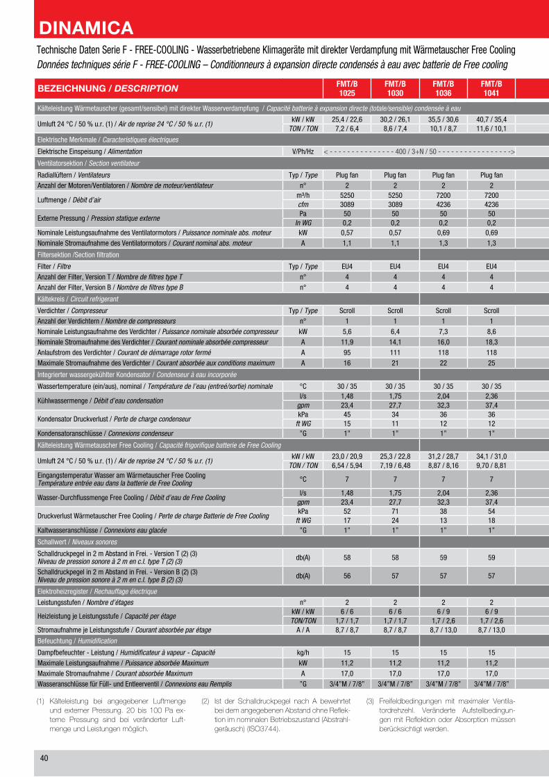
�0
(1) Kälteleistung bei angegebener LuftmengeundexternerPressung. 20bis 100Pa ex-terne Pressung sind bei veränderter Luft-mengeundLeistungenmöglich.
(2) Ist der Schalldruckpegel nach A bewehrtetbeidemangegebenenAbstandohneReflek-tionimnominalenBetriebszustand(Abstrahl-geräusch)(ISO3744).
(3) Freifeldbedingungen mit maximaler Ventila-tordrehzehl. Veränderte Aufstellbedingun-genmitReflektionoderAbsorptionmüssenberücksichtigtwerden.
BEZEICHNUNG / DESCRIPTION FMT/B1025
FMT/B1030
FMT/B1036
FMT/B1041
FMT/B1053
FMT/B1066
FMT/B2031
FMT/B2041
FMT/B2055
FMT/B2064
FMT/B2074
FMT/B2083
FLT/B2104
FLT/B2134
Kälteleistung Wärmetauscher (gesamt/sensibel) mit direkter Wasserverdampfung / Capacité batterie à expansion directe (totale/sensible) condensée à eau
Umluft �� °C / �0 % u.r. (1) / Air de reprise 24 °C / 50 % u.r. (1)kW / kW ��,� / ��,� �0,� / ��,1 ��,� / �0,� �0,� / ��,� ��,� / ��,1 ��,1 / ��,� �1,� / �0,� �1,� / �1,1 ��,� / ��,0 ��,� / ��,� ��,�/ ��,0 ��,� / ��,� 10�,0 / 10�,0 1��,� / 1��,�
TON / TON �,� / �,� �,� / �,� 10,1 / �,� 11,� / 10,1 1�,0 / 1�,1 1�,� / 1�,1 �,� / �,� 11,� / 11,� 1�,� / 1�,� 1�,� / 1�,0 �1,0 / �1,0 ��,� / ��,� ��,� / ��,� ��,0 / ��,0
Elektrische Merkmale / Caracteristiques électriques
Elektrische Einspeisung / Alimentation V/Ph/Hz < - - - - - - - - - - - - - - - �00 / �+N / �0 - - - - - - - - - - - - - - - - -> < - - - - - - - - - - - - - - - - - - - - - - - - - - - - - - - - - - - - - - - - - - - - - �00 / �+N / �0 - - - - - - - - - - - - - - - - - - - - - - - - - - - - - - - - - - - - - - - - - - - - - - ->
Ventilatorsektion / Section ventilateur
Radiallüftern / Ventilateurs Typ / Type Plug fan Plug fan Plug fan Plug fan Plug fan Plug fan Plug fan Plug fan Plug fan Plug fan Plug fan Plug fan Plug fan Plug fanAnzahl der Motoren/Ventilatoren / Nombre de moteur/ventilateur n° � � � � � � � � � � � � � �
Luftmenge / Débit d’airm³/h ���0 ���0 ��00 ��00 10�00 11��0 ���0 ��00 10�00 11��0 1��00 1��00 1�000 ��000cfm �0�� �0�� ���� ���� �001 ��1� �0�� ���� �001 ��1� ���� ���� 10��0 1�1�0
Externe Pressung / Pression statique externePa �0 �0 �0 �0 �0 �0 �0 �0 �0 �0 �0 �0 �0 �0
In WG 0,� 0,� 0,� 0,� 0,� 0,� 0,� 0,� 0,� 0,� 0,� 0,� 0,� 0,�Nominale Leistungsaufnahme des Ventilatormotors / Puissance nominale abs. moteur kW 0,�� 0,�� 0,�� 0,�� 0,�� 0,�� 0,�� 0,�� 0,�� 0,�� 0,�� 0,�� 0,�� 0,��Nominale Stromaufnahme des Ventilatormotors / Courant nominal abs. moteur A 1,1 1,1 1,� 1,� 1,� 1,� 1,1 1,� 1,� 1,� 1,� 1,� 1,� 1,�
Filtersektion /Section filtration
Filter / Filtre Typ / Type EU� EU� EU� EU� EU� EU� EU� EU� EU� EU� EU� EU� EU� EU�Anzahl der Filter, Version T / Nombre de filtres type T n° � � � � � � � � � � � � � 10Anzahl der Filter, Version B / Nombre de filtres type B n° � � � � � � � � � � � � 10 10
Kältekreis / Circuit refrigerant
Verdichter / Compresseur Typ / Type Scroll Scroll Scroll Scroll Scroll Scroll Scroll Scroll Scroll Scroll Scroll Scroll Scroll ScrollAnzahl der Verdichtern / Nombre de compresseurs n° 1 1 1 1 1 1 � � � � � � � �Nominale Leistungsaufnahme des Verdichter / Puissance nominale absorbée compresseur kW �,� �,� �,� �,� 11,� 1�,� �,� �,� �,� �,� �,� �,� 11,� 1�,�Nominale Stromaufnahme des Verdichter / Courant nominale absorbée compresseur A 11,� 1�,1 1�,0 1�,� ��,1 ��,� �,� �,� 1�,� 1�,� 1�,� 1�,0 ��,� ��,�Anlaufstrom des Verdichter / Courant de démarrage rotor fermé A �� 111 11� 11� 1�� ��� �1 �� �� 111 11� 11� 1�� ���Maximale Stromaufnahme des Verdichter / Courant absorbée aux conditions maximum A 1� �1 �� �� �� �0 10 1� 1� �1 �� �� �� �0
Integrierter wassergekühlter Kondensator / Condenseur à eau incorporée
Wassertemperature (ein/aus), nominal / Température de l’eau (entreé/sortie) nominale °C �0 / �� �0 / �� �0 / �� �0 / �� �0 / �� �0 / �� �0 / �� �0 / �� �0 / �� �0 / �� �0 / �� �0 / �� �0 / �� �0 / ��
Kühlwassermenge / Débit d’eau condensationl/s 1,�� 1,�� �,0� �,�� �,0� �,�� 1,�� �,1� �,�� �,�� �,�� �,�� �,�0 �,0�
gpm ��,� ��,� ��,� ��,� ��,� �1,1 ��,1 ��,� ��,� ��,� �1,� ��,1 ��,1 11�,�
Kondensator Druckverlust / Perte de charge condenseurkPa �� �� �� �� �� �� �1 �0 �� �� �� �� �1 ��
ft WG 1� 11 1� 1� 1� 1� 10 1� 1� 1� 1� 1� 1� 1�Kondensatoranschlüsse / Connexions condenseur ”G 1” 1” 1” 1” 1” 1”1/� � x 1” � x 1” � x 1” � x 1” � x 1” � x 1” � x 1” � x 1”1/�
Kälteleistung Wärmetauscher Free Cooling / Capacité frigorifique batterie de Free Cooling
Umluft �� °C / �0 % u.r. (1) / Air de reprise 24 °C / 50 % u.r. (1)kW / kW ��,0 / �0,� ��,� / ��,� �1,� / ��,� ��,1 / �1,0 ��,1 / ��,� �1,� / ��,0 ��,� / ��,� ��,� / ��,� ��,� / ��,� �0,� / ��,� ��,� / ��,� ��,� / �0,0 ��,0 / ��,� 10� / ��,�
TON / TON �,�� / �,�� �,1� / �,�� �,�� / �,1� �,�0 / �,�1 1�,�� / 1�,00 1�,�0 / 1�,0� �,�� / �,�1 �,�0 / �,�� 1�,1� / 1�,0� 1�,�0 / 1�,1� 1�,�� / 1�,�� 1�,�� / 1�,0� ��,�� / �0,�� ��,�� / ��,��Eingangstemperatur Wasser am Wärmetauscher Free CoolingTempérature entrée eau dans la batterie de Free Cooling °C � � � � � � � � � � � � � �
Wasser-Durchflussmenge Free Cooling / Débit d’eau de Free Coolingl/s 1,�� 1,�� �,0� �,�� �,0� �,�� 1,�� �,1� �,�� �,�� �,�� �,�� �,�0 �,0�
gpm ��,� ��,� ��,� ��,� ��,� �1,1 ��,1 ��,� ��,� ��,� �1,� ��,1 ��,1 11�,�
Druckverlust Wärmetauscher Free Cooling / Perte de charge Batterie de Free CoolingkPa �� �1 �� �� �� �� �� �� �� �1 �� �� �� 11�
ft WG 1� �� 1� 1� � 1� �1 1� � � 1� �1 �� ��Kaltwasseranschlüsse / Connexions eau glacée ”G 1” 1” 1” 1” 1” 1”1/� � x 1” � x 1” � x 1” � x 1” � x 1” � x 1” � x 1” � x 1”1/�
Schallwert / Niveaux sonores
Schalldruckpegel in � m Abstand in Frei. - Version T (�) (�)Niveau de pression sonore à 2 m en c.l. type T (2) (3) db(A) �� �� �� �� �� �� �� �� �0 �� �� �� �� �0
Schalldruckpegel in � m Abstand in Frei. - Version B (�) (�)Niveau de pression sonore à 2 m en c.l. type B (2) (3) db(A) �� �� �� �� �0 �0 �� �� �� �0 �0 �0 �� ��
Elektroheizregister / Rechauffage électrique
Leistungsstufen / Nombre d’étages n° � � � � � � � � � � � � � �
Heizleistung je Leistungsstufe / Capacité per étagekW / kW � / � � / � � / � � / � � / � � / � � / � � / � � / � � / � 1� / 1� 1� / 1� 1� / 1� 1� / 1�TON/TON 1,� / 1,� 1,� / 1,� 1,� / �,� 1,� / �,� 1,� / �,� 1,� / �,� 1,� / �,� 1,� / �,� 1,� / �,� 1,� / �,� �,� / �,� �,� / �,� �,� / �,� �,� / �,�
Stromaufnahme je Leistungsstufe / Courant absorbée par étage A / A �,� / �,� �,� / �,� �,� / 1�,0 �,� / 1�,0 �,� / 1�,0 �,� / 1�,0 �,� / 1�,0 �,� / 1�,0 �,� / 1�,0 �,� / 1�,0 1�,1 / 1�,1 1�,1 / 1�,1 1�,1 / 1�,1 1�,1 / 1�,1
Befeuchtung / Humidification
Dampfbefeuchter - Leistung / Humidificateur à vapeur - Capacité kg/h 1� 1� 1� 1� 1� 1� 1� 1� 1� 1� 1� 1� 1� 1�Maximale Leistungsaufnahme / Puissance absorbée Maximum kW 11,� 11,� 11,� 11,� 11,� 11,� 11,� 11,� 11,� 11,� 11,� 11,� 11,� 11,�Maximale Stromaufnahme / Courant absorbée Maximum A 1�,0 1�,0 1�,0 1�,0 1�,0 1�,0 1�,0 1�,0 1�,0 1�,0 1�,0 1�,0 1�,0 1�,0Wasseranschlüsse für Füll- und Entleerventil / Connexions eau Remplis ”G �/�”M / �/�” �/�”M / �/�” �/�”M / �/�” �/�”M / �/�” �/�”M / �/�” �/�”M / �/�” �/�”M / �/�” �/�”M / �/�” �/�”M / �/�” �/�”M / �/�” �/�”M / �/�” �/�”M / �/�” �/�”M / �/�” �/�”M / �/�”
Technische Daten Serie F - FREE-COOLING - Wasserbetriebene Klimageräte mit direkter Verdampfung mit Wärmetauscher Free CoolingDonnées techniques série F - FREE-COOLING – Conditionneurs à expansion directe condensés à eau avec batterie de Free cooling
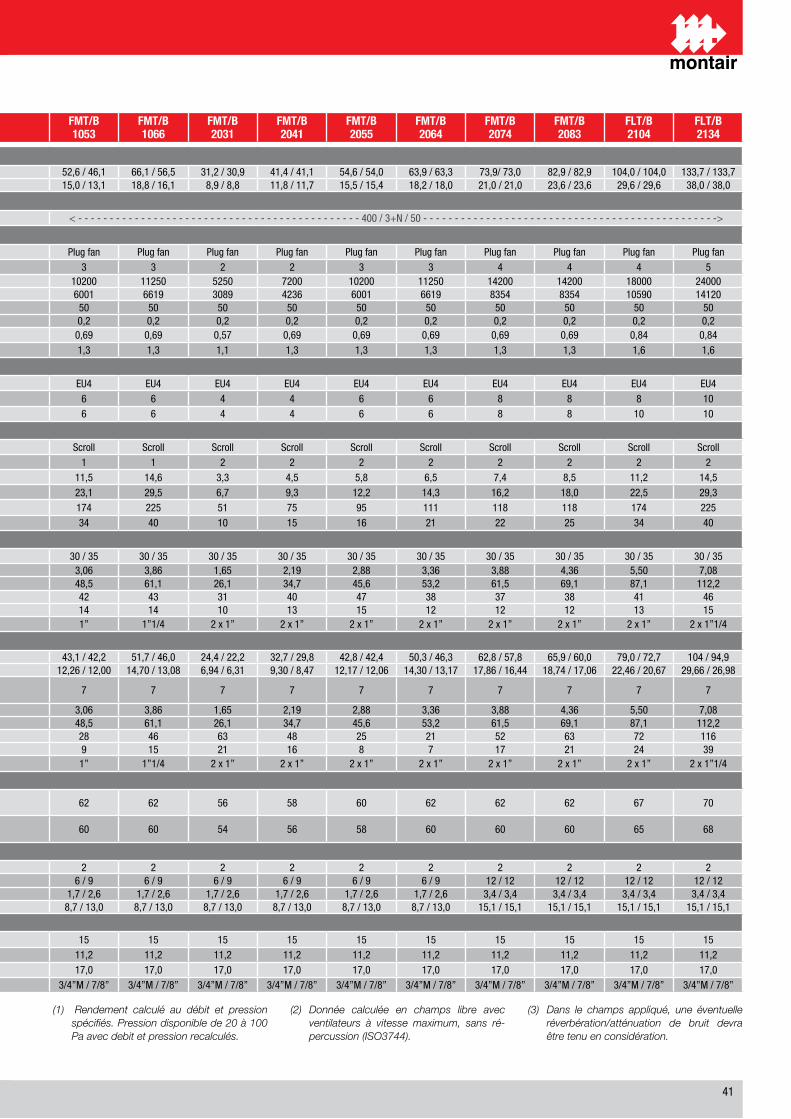
�1
(1) Rendement calculé au débit et pression spécifiés. Pression disponible de 20 à 100 Pa avec debit et pression recalculés.
(2) Donnée calculée en champs libre avec ventilateurs à vitesse maximum, sans ré-percussion (ISO3744).
(3) Dans le champs appliqué, une éventuelle réverbération/atténuation de bruit devra être tenu en considération.
BEZEICHNUNG / DESCRIPTION FMT/B1025
FMT/B1030
FMT/B1036
FMT/B1041
FMT/B1053
FMT/B1066
FMT/B2031
FMT/B2041
FMT/B2055
FMT/B2064
FMT/B2074
FMT/B2083
FLT/B2104
FLT/B2134
Kälteleistung Wärmetauscher (gesamt/sensibel) mit direkter Wasserverdampfung / Capacité batterie à expansion directe (totale/sensible) condensée à eau
Umluft �� °C / �0 % u.r. (1) / Air de reprise 24 °C / 50 % u.r. (1)kW / kW ��,� / ��,� �0,� / ��,1 ��,� / �0,� �0,� / ��,� ��,� / ��,1 ��,1 / ��,� �1,� / �0,� �1,� / �1,1 ��,� / ��,0 ��,� / ��,� ��,�/ ��,0 ��,� / ��,� 10�,0 / 10�,0 1��,� / 1��,�
TON / TON �,� / �,� �,� / �,� 10,1 / �,� 11,� / 10,1 1�,0 / 1�,1 1�,� / 1�,1 �,� / �,� 11,� / 11,� 1�,� / 1�,� 1�,� / 1�,0 �1,0 / �1,0 ��,� / ��,� ��,� / ��,� ��,0 / ��,0
Elektrische Merkmale / Caracteristiques électriques
Elektrische Einspeisung / Alimentation V/Ph/Hz < - - - - - - - - - - - - - - - �00 / �+N / �0 - - - - - - - - - - - - - - - - -> < - - - - - - - - - - - - - - - - - - - - - - - - - - - - - - - - - - - - - - - - - - - - - �00 / �+N / �0 - - - - - - - - - - - - - - - - - - - - - - - - - - - - - - - - - - - - - - - - - - - - - - ->
Ventilatorsektion / Section ventilateur
Radiallüftern / Ventilateurs Typ / Type Plug fan Plug fan Plug fan Plug fan Plug fan Plug fan Plug fan Plug fan Plug fan Plug fan Plug fan Plug fan Plug fan Plug fanAnzahl der Motoren/Ventilatoren / Nombre de moteur/ventilateur n° � � � � � � � � � � � � � �
Luftmenge / Débit d’airm³/h ���0 ���0 ��00 ��00 10�00 11��0 ���0 ��00 10�00 11��0 1��00 1��00 1�000 ��000cfm �0�� �0�� ���� ���� �001 ��1� �0�� ���� �001 ��1� ���� ���� 10��0 1�1�0
Externe Pressung / Pression statique externePa �0 �0 �0 �0 �0 �0 �0 �0 �0 �0 �0 �0 �0 �0
In WG 0,� 0,� 0,� 0,� 0,� 0,� 0,� 0,� 0,� 0,� 0,� 0,� 0,� 0,�Nominale Leistungsaufnahme des Ventilatormotors / Puissance nominale abs. moteur kW 0,�� 0,�� 0,�� 0,�� 0,�� 0,�� 0,�� 0,�� 0,�� 0,�� 0,�� 0,�� 0,�� 0,��Nominale Stromaufnahme des Ventilatormotors / Courant nominal abs. moteur A 1,1 1,1 1,� 1,� 1,� 1,� 1,1 1,� 1,� 1,� 1,� 1,� 1,� 1,�
Filtersektion /Section filtration
Filter / Filtre Typ / Type EU� EU� EU� EU� EU� EU� EU� EU� EU� EU� EU� EU� EU� EU�Anzahl der Filter, Version T / Nombre de filtres type T n° � � � � � � � � � � � � � 10Anzahl der Filter, Version B / Nombre de filtres type B n° � � � � � � � � � � � � 10 10
Kältekreis / Circuit refrigerant
Verdichter / Compresseur Typ / Type Scroll Scroll Scroll Scroll Scroll Scroll Scroll Scroll Scroll Scroll Scroll Scroll Scroll ScrollAnzahl der Verdichtern / Nombre de compresseurs n° 1 1 1 1 1 1 � � � � � � � �Nominale Leistungsaufnahme des Verdichter / Puissance nominale absorbée compresseur kW �,� �,� �,� �,� 11,� 1�,� �,� �,� �,� �,� �,� �,� 11,� 1�,�Nominale Stromaufnahme des Verdichter / Courant nominale absorbée compresseur A 11,� 1�,1 1�,0 1�,� ��,1 ��,� �,� �,� 1�,� 1�,� 1�,� 1�,0 ��,� ��,�Anlaufstrom des Verdichter / Courant de démarrage rotor fermé A �� 111 11� 11� 1�� ��� �1 �� �� 111 11� 11� 1�� ���Maximale Stromaufnahme des Verdichter / Courant absorbée aux conditions maximum A 1� �1 �� �� �� �0 10 1� 1� �1 �� �� �� �0
Integrierter wassergekühlter Kondensator / Condenseur à eau incorporée
Wassertemperature (ein/aus), nominal / Température de l’eau (entreé/sortie) nominale °C �0 / �� �0 / �� �0 / �� �0 / �� �0 / �� �0 / �� �0 / �� �0 / �� �0 / �� �0 / �� �0 / �� �0 / �� �0 / �� �0 / ��
Kühlwassermenge / Débit d’eau condensationl/s 1,�� 1,�� �,0� �,�� �,0� �,�� 1,�� �,1� �,�� �,�� �,�� �,�� �,�0 �,0�
gpm ��,� ��,� ��,� ��,� ��,� �1,1 ��,1 ��,� ��,� ��,� �1,� ��,1 ��,1 11�,�
Kondensator Druckverlust / Perte de charge condenseurkPa �� �� �� �� �� �� �1 �0 �� �� �� �� �1 ��
ft WG 1� 11 1� 1� 1� 1� 10 1� 1� 1� 1� 1� 1� 1�Kondensatoranschlüsse / Connexions condenseur ”G 1” 1” 1” 1” 1” 1”1/� � x 1” � x 1” � x 1” � x 1” � x 1” � x 1” � x 1” � x 1”1/�
Kälteleistung Wärmetauscher Free Cooling / Capacité frigorifique batterie de Free Cooling
Umluft �� °C / �0 % u.r. (1) / Air de reprise 24 °C / 50 % u.r. (1)kW / kW ��,0 / �0,� ��,� / ��,� �1,� / ��,� ��,1 / �1,0 ��,1 / ��,� �1,� / ��,0 ��,� / ��,� ��,� / ��,� ��,� / ��,� �0,� / ��,� ��,� / ��,� ��,� / �0,0 ��,0 / ��,� 10� / ��,�
TON / TON �,�� / �,�� �,1� / �,�� �,�� / �,1� �,�0 / �,�1 1�,�� / 1�,00 1�,�0 / 1�,0� �,�� / �,�1 �,�0 / �,�� 1�,1� / 1�,0� 1�,�0 / 1�,1� 1�,�� / 1�,�� 1�,�� / 1�,0� ��,�� / �0,�� ��,�� / ��,��Eingangstemperatur Wasser am Wärmetauscher Free CoolingTempérature entrée eau dans la batterie de Free Cooling °C � � � � � � � � � � � � � �
Wasser-Durchflussmenge Free Cooling / Débit d’eau de Free Coolingl/s 1,�� 1,�� �,0� �,�� �,0� �,�� 1,�� �,1� �,�� �,�� �,�� �,�� �,�0 �,0�
gpm ��,� ��,� ��,� ��,� ��,� �1,1 ��,1 ��,� ��,� ��,� �1,� ��,1 ��,1 11�,�
Druckverlust Wärmetauscher Free Cooling / Perte de charge Batterie de Free CoolingkPa �� �1 �� �� �� �� �� �� �� �1 �� �� �� 11�
ft WG 1� �� 1� 1� � 1� �1 1� � � 1� �1 �� ��Kaltwasseranschlüsse / Connexions eau glacée ”G 1” 1” 1” 1” 1” 1”1/� � x 1” � x 1” � x 1” � x 1” � x 1” � x 1” � x 1” � x 1”1/�
Schallwert / Niveaux sonores
Schalldruckpegel in � m Abstand in Frei. - Version T (�) (�)Niveau de pression sonore à 2 m en c.l. type T (2) (3) db(A) �� �� �� �� �� �� �� �� �0 �� �� �� �� �0
Schalldruckpegel in � m Abstand in Frei. - Version B (�) (�)Niveau de pression sonore à 2 m en c.l. type B (2) (3) db(A) �� �� �� �� �0 �0 �� �� �� �0 �0 �0 �� ��
Elektroheizregister / Rechauffage électrique
Leistungsstufen / Nombre d’étages n° � � � � � � � � � � � � � �
Heizleistung je Leistungsstufe / Capacité per étagekW / kW � / � � / � � / � � / � � / � � / � � / � � / � � / � � / � 1� / 1� 1� / 1� 1� / 1� 1� / 1�TON/TON 1,� / 1,� 1,� / 1,� 1,� / �,� 1,� / �,� 1,� / �,� 1,� / �,� 1,� / �,� 1,� / �,� 1,� / �,� 1,� / �,� �,� / �,� �,� / �,� �,� / �,� �,� / �,�
Stromaufnahme je Leistungsstufe / Courant absorbée par étage A / A �,� / �,� �,� / �,� �,� / 1�,0 �,� / 1�,0 �,� / 1�,0 �,� / 1�,0 �,� / 1�,0 �,� / 1�,0 �,� / 1�,0 �,� / 1�,0 1�,1 / 1�,1 1�,1 / 1�,1 1�,1 / 1�,1 1�,1 / 1�,1
Befeuchtung / Humidification
Dampfbefeuchter - Leistung / Humidificateur à vapeur - Capacité kg/h 1� 1� 1� 1� 1� 1� 1� 1� 1� 1� 1� 1� 1� 1�Maximale Leistungsaufnahme / Puissance absorbée Maximum kW 11,� 11,� 11,� 11,� 11,� 11,� 11,� 11,� 11,� 11,� 11,� 11,� 11,� 11,�Maximale Stromaufnahme / Courant absorbée Maximum A 1�,0 1�,0 1�,0 1�,0 1�,0 1�,0 1�,0 1�,0 1�,0 1�,0 1�,0 1�,0 1�,0 1�,0Wasseranschlüsse für Füll- und Entleerventil / Connexions eau Remplis ”G �/�”M / �/�” �/�”M / �/�” �/�”M / �/�” �/�”M / �/�” �/�”M / �/�” �/�”M / �/�” �/�”M / �/�” �/�”M / �/�” �/�”M / �/�” �/�”M / �/�” �/�”M / �/�” �/�”M / �/�” �/�”M / �/�” �/�”M / �/�”
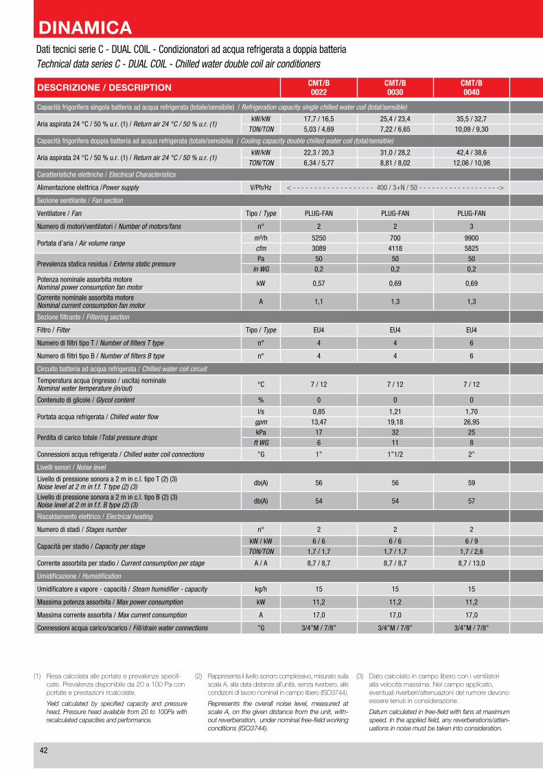
��
DESCRIZIONE / DESCRIPTION CMT/B0022
CMT/B0030
CMT/B0040
CMT/B0046
CMT/B0060
CMT/B0076
CMT/B0102 BEZEICHNUNG / DESCRIPTION
Capacità frigorifera singola batteria ad acqua refrigerata (totale/sensibile) / Refrigeration capacity single chilled water coil (total/sensible) Kälteleistung pro Kaltwassersatz (gesamt/sensibel) / Capacité frigorifique de chaque batterie à eau réfrigérée (totale/sensible)
Aria aspirata �� °C / �0 % u.r. (1) / Return air 24 °C / 50 % u.r. (1)kW/kW 1�,� / 1�,� ��,� / ��,� ��,� / ��,� �1,0 / ��,� ��,� / �0,0 �0,� / ��,� �0,� / ��,� kW/kW
Umluft �� °C / �0 % u.r. (1) / Air de reprise 24 °C / 50 % u.r. (1)TON/TON �,0� / �,�� �,�� / �,�� 10,0� / �,�0 11,�� / 10,�1 1�,�� / 1�,�� 1�,�� / 1�,�� ��,0 / �1,�� TON/TON
Capacità frigorifera doppia batteria ad acqua refrigerata (totale/sensibile) / Cooling capacity double chilled water coil (total/sensible) Kälteleistung zwei Kaltwassersätze (gesamt/sensibel) / Capacité frigorifique deux batteries à eau réfrigérée (totale/sensible)
Aria aspirata �� °C / �0 % u.r. (1) / Return air 24 °C / 50 % u.r. (1)kW/kW ��,� / �0,� �1,0 / ��,� ��,� / ��,� ��,0 / ��,1 ��,� / �0,� ��,� / �0,� 10� / ��,� kW/kW
Umluft �� °C / �0 % u.r. (1) / Air de reprise 24 °C / 50 % u.r. (1)TON/TON �,�� / �,�� �,�1 / �,0� 1�,0� / 10,�� 1�,�� / 1�,�� 1�,�1 / 1�,1� ��,0� / �0,10 �0,1� / ��,�1 TON/TON
Caratteristiche elettriche / Electrical Characteristics Elektrische Merkmale / Caracteristiques électriques
Alimentazione elettrica /Power supply V/Ph/Hz < - - - - - - - - - - - - - - - - - - - �00 / �+N / �0 - - - - - - - - - - - - - - - - - - -> < - - - - - - - - - - - - - - - - - - - �00 / �+N / �0 - - - - - - - - - - - - - - - - - - -> V/Ph/Hz Elektrische Einspeisung / Alimentation
Sezione ventilante / Fan section Ventilatorsektion / Section ventilateur
Ventilatore / Fan Tipo / Type PLUG-FAN PLUG-FAN PLUG-FAN PLUG-FAN PLUG-FAN PLUG-FAN PLUG-FAN Typ / Type Radiallüftern / Ventilateurs
Numero di motori/ventilatori / Number of motors/fans n° � � � � � � � n° Anzahl der Motoren/Ventilatoren / Nombre de moteur/ventilateur
Portata d’aria / Air volume rangem³/h ���0 �00 ��00 10�00 1��00 1��00 ���00 m³/h
Luftmenge / Débit d’aircfm �0�� �11� ���� ���� �001 10��� 1���� cfm
Prevalenza statica residua / Externa static pressurePa �0 �0 �0 �0 �0 �0 �0 Pa
Externe Pressung / Pression statique externeIn WG 0,� 0,� 0,� 0,� 0,� 0,� 0,� In WG
Potenza nominale assorbita motoreNominal power consumption fan motor kW 0,�� 0,�� 0,�� 0,�� 0,�� 0,�� 0,�� kW Nominale Leistungsaufnahme des Ventilatormotors
Puissance nominale abs. moteurCorrente nominale assorbita motoreNominal current consumption fan motor A 1,1 1,� 1,� 1,� 1,� 1,� 1,� A Nominale Stromaufnahme des Ventilatormotors
Courant nominal abs. moteur
Sezione filtrante / Filtering section Filtersektion /Section filtration
Filtro / Filter Tipo / Type EU� EU� EU� EU� EU� EU� EU� Typ / Type Filter / Filtre
Numero di filtri tipo T / Number of filters T type n° � � � � � � 10 n° Anzahl der Filter, Version T / Nombre de filtres type T
Numero di filtri tipo B / Number of filters B type n° � � � � � 10 10 n° Anzahl der Filter, Version B / Nombre de filtres type B
Circuito batteria ad acqua refrigerata / Chilled water coil circuit Kühlschlange / Circuit batterie à eau réfrigérée
Temperatura acqua (ingresso / uscita) nominaleNominal water temperature (in/out) °C � / 1� � / 1� � / 1� � / 1� � / 1� � / 1� � / 1� °C Wassertemperature (ein / aus) nominal
Temperature d’eau entrée (entrée / sortie)
Contenuto di glicole / Glycol content % 0 0 0 0 0 0 0 % Glycolanteil / Glycol
Portata acqua refrigerata / Chilled water flowl/s 0,�� 1,�1 1,�0 1,�� �,�0 �,�0 �,�� l/s
Kaltwassermenge / Débit d’eau glacéegpm 1�,�� 1�,1� ��,�� �1,0� �1,�1 ��,�� �1,�� gpm
Perdita di carico totale /Total pressure dropskPa 1� �� �� �� �� 1� �� kPa
Druckverlust total / Perte de charge totalft WG � 11 � 1� �1 � � ft WG
Connessioni acqua refrigerata / Chilled water coil connections ”G 1” 1”1/� �” �” �” �” �”1/� ”G Kaltwasseranschlüsse / Connexions eau glacée
Livelli sonori / Noise level Schallwert / Niveaux sonores
Livello di pressione sonora a � m in c.l. tipo T (�) (�)Noise level at 2 m in f.f. T type (2) (3) db(A) �� �� �� �� �0 �� �� db(A) Schalldruckpegel in � m Abstand in Frei. - Version T (�) (�)
Niveau de pression sonore à 2 m en c.l. type T (2) (3)Livello di pressione sonora a � m in c.l. tipo B (�) (�)Noise level at 2 m in f.f. B type (2) (3) db(A) �� �� �� �� �� �� �� db(A) Schalldruckpegel in � m Abstand in Frei. - Version B (�) (�)
Niveau de pression sonore à 2 m en c.l. type B (2) (3)
Riscaldamento elettrico / Electrical heating Elektroheizregister / Rechauffage électrique
Numero di stadi / Stages number n° � � � � � � � n° Leistungsstufen / Nombre d’étages
Capacità per stadio / Capacity per stagekW / kW � / � � / � � / � � / � � / � 1� / 1� 1� / 1� kW / kW
Heizleistung je Leistungsstufe / Capacité per étageTON/TON 1,� / 1,� 1,� / 1,� 1,� / �,� 1,� / �,� �,� / �,� �,� / �,� �,� / �,� TON/TON
Corrente assorbita per stadio / Current consumption per stage A / A �,� / �,� �,� / �,� �,� / 1�,0 �,� / 1�,0 �,� / 1�,0 1�,1 / 1�,1 1�,1 / 1�,1 A / A Stromaufnahme je Leistungsstufe / Courant absorbée par étage
Umidificazione / Humidification Befeuchtung / Humidification
Umidificatore a vapore - capacità / Steam humidifier - capacity kg/h 1� 1� 1� 1� 1� 1� 1� kg/h Dampfbefeuchter - Leistung / Humidificateur à vapeur - Capacité
Massima potenza assorbita / Max power consumption kW 11,� 11,� 11,� 11,� 11,� 11,� 11,� kW Maximale Leistungsaufnahme / Puissance absorbée Maximum
Massima corrente assorbita / Max current consumption A 1�,0 1�,0 1�,0 1�,0 1�,0 1�,0 1�,0 A Maximale Stromaufnahme / Courant absorbée Maximum
Connessioni acqua carico/scarico / Fill/drain water connections ”G �/�”M / �/�” �/�”M / �/�” �/�”M / �/�” �/�”M / �/�” �/�”M / �/�” �/�”M / �/�” �/�”M / �/�” ”G / mm Wasseranschlüsse für Füll- und Entleerventil / Connexions eau Remplis
(1) Resacalcolataalleportateeprevalenzespecifi-cate.Prevalenzadisponibileda20a100Paconportateeprestazioniricalcolate.
Yield calculated by specified capacity and pressure head. Pressure head available from 20 to 100Pa with recalculated capacities and performance.
(2) Rappresentaililvellosonorocomplessivo,misuratosullascalaA,alladatadistanzaall’unità,senzariverbero,allecondizionidilavoronominaliincampolibero(ISO3744).
Represents the overall noise level, measured at scale A, on the given distance from the unit, with-out reverberation, under nominal free-field working conditions (ISO3744).
(3) Datocalcolatoincampoliberoconiventilatoriallavelocitàmassima.Nelcampoapplicato,eventualiriverberi/attenuazionidelrumoredevonoesseretenutiinconsiderazione.
Datum calculated in free-field with fans at maximum speed. In the applied field, any reverberations/atten-uations in noise must be taken into consideration.
Dati tecnici serie C - DUAL COIL - Condizionatori ad acqua refrigerata a doppia batteria Technical data series C - DUAL COIL - Chilled water double coil air conditioners
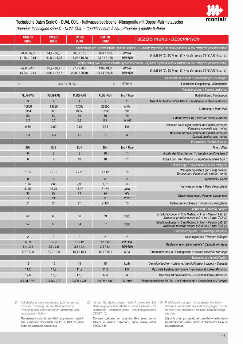
��
DESCRIZIONE / DESCRIPTION CMT/B0022
CMT/B0030
CMT/B0040
CMT/B0046
CMT/B0060
CMT/B0076
CMT/B0102 BEZEICHNUNG / DESCRIPTION
Capacità frigorifera singola batteria ad acqua refrigerata (totale/sensibile) / Refrigeration capacity single chilled water coil (total/sensible) Kälteleistung pro Kaltwassersatz (gesamt/sensibel) / Capacité frigorifique de chaque batterie à eau réfrigérée (totale/sensible)
Aria aspirata �� °C / �0 % u.r. (1) / Return air 24 °C / 50 % u.r. (1)kW/kW 1�,� / 1�,� ��,� / ��,� ��,� / ��,� �1,0 / ��,� ��,� / �0,0 �0,� / ��,� �0,� / ��,� kW/kW
Umluft �� °C / �0 % u.r. (1) / Air de reprise 24 °C / 50 % u.r. (1)TON/TON �,0� / �,�� �,�� / �,�� 10,0� / �,�0 11,�� / 10,�1 1�,�� / 1�,�� 1�,�� / 1�,�� ��,0 / �1,�� TON/TON
Capacità frigorifera doppia batteria ad acqua refrigerata (totale/sensibile) / Cooling capacity double chilled water coil (total/sensible) Kälteleistung zwei Kaltwassersätze (gesamt/sensibel) / Capacité frigorifique deux batteries à eau réfrigérée (totale/sensible)
Aria aspirata �� °C / �0 % u.r. (1) / Return air 24 °C / 50 % u.r. (1)kW/kW ��,� / �0,� �1,0 / ��,� ��,� / ��,� ��,0 / ��,1 ��,� / �0,� ��,� / �0,� 10� / ��,� kW/kW
Umluft �� °C / �0 % u.r. (1) / Air de reprise 24 °C / 50 % u.r. (1)TON/TON �,�� / �,�� �,�1 / �,0� 1�,0� / 10,�� 1�,�� / 1�,�� 1�,�1 / 1�,1� ��,0� / �0,10 �0,1� / ��,�1 TON/TON
Caratteristiche elettriche / Electrical Characteristics Elektrische Merkmale / Caracteristiques électriques
Alimentazione elettrica /Power supply V/Ph/Hz < - - - - - - - - - - - - - - - - - - - �00 / �+N / �0 - - - - - - - - - - - - - - - - - - -> < - - - - - - - - - - - - - - - - - - - �00 / �+N / �0 - - - - - - - - - - - - - - - - - - -> V/Ph/Hz Elektrische Einspeisung / Alimentation
Sezione ventilante / Fan section Ventilatorsektion / Section ventilateur
Ventilatore / Fan Tipo / Type PLUG-FAN PLUG-FAN PLUG-FAN PLUG-FAN PLUG-FAN PLUG-FAN PLUG-FAN Typ / Type Radiallüftern / Ventilateurs
Numero di motori/ventilatori / Number of motors/fans n° � � � � � � � n° Anzahl der Motoren/Ventilatoren / Nombre de moteur/ventilateur
Portata d’aria / Air volume rangem³/h ���0 �00 ��00 10�00 1��00 1��00 ���00 m³/h
Luftmenge / Débit d’aircfm �0�� �11� ���� ���� �001 10��� 1���� cfm
Prevalenza statica residua / Externa static pressurePa �0 �0 �0 �0 �0 �0 �0 Pa
Externe Pressung / Pression statique externeIn WG 0,� 0,� 0,� 0,� 0,� 0,� 0,� In WG
Potenza nominale assorbita motoreNominal power consumption fan motor kW 0,�� 0,�� 0,�� 0,�� 0,�� 0,�� 0,�� kW Nominale Leistungsaufnahme des Ventilatormotors
Puissance nominale abs. moteurCorrente nominale assorbita motoreNominal current consumption fan motor A 1,1 1,� 1,� 1,� 1,� 1,� 1,� A Nominale Stromaufnahme des Ventilatormotors
Courant nominal abs. moteur
Sezione filtrante / Filtering section Filtersektion /Section filtration
Filtro / Filter Tipo / Type EU� EU� EU� EU� EU� EU� EU� Typ / Type Filter / Filtre
Numero di filtri tipo T / Number of filters T type n° � � � � � � 10 n° Anzahl der Filter, Version T / Nombre de filtres type T
Numero di filtri tipo B / Number of filters B type n° � � � � � 10 10 n° Anzahl der Filter, Version B / Nombre de filtres type B
Circuito batteria ad acqua refrigerata / Chilled water coil circuit Kühlschlange / Circuit batterie à eau réfrigérée
Temperatura acqua (ingresso / uscita) nominaleNominal water temperature (in/out) °C � / 1� � / 1� � / 1� � / 1� � / 1� � / 1� � / 1� °C Wassertemperature (ein / aus) nominal
Temperature d’eau entrée (entrée / sortie)
Contenuto di glicole / Glycol content % 0 0 0 0 0 0 0 % Glycolanteil / Glycol
Portata acqua refrigerata / Chilled water flowl/s 0,�� 1,�1 1,�0 1,�� �,�0 �,�0 �,�� l/s
Kaltwassermenge / Débit d’eau glacéegpm 1�,�� 1�,1� ��,�� �1,0� �1,�1 ��,�� �1,�� gpm
Perdita di carico totale /Total pressure dropskPa 1� �� �� �� �� 1� �� kPa
Druckverlust total / Perte de charge totalft WG � 11 � 1� �1 � � ft WG
Connessioni acqua refrigerata / Chilled water coil connections ”G 1” 1”1/� �” �” �” �” �”1/� ”G Kaltwasseranschlüsse / Connexions eau glacée
Livelli sonori / Noise level Schallwert / Niveaux sonores
Livello di pressione sonora a � m in c.l. tipo T (�) (�)Noise level at 2 m in f.f. T type (2) (3) db(A) �� �� �� �� �0 �� �� db(A) Schalldruckpegel in � m Abstand in Frei. - Version T (�) (�)
Niveau de pression sonore à 2 m en c.l. type T (2) (3)Livello di pressione sonora a � m in c.l. tipo B (�) (�)Noise level at 2 m in f.f. B type (2) (3) db(A) �� �� �� �� �� �� �� db(A) Schalldruckpegel in � m Abstand in Frei. - Version B (�) (�)
Niveau de pression sonore à 2 m en c.l. type B (2) (3)
Riscaldamento elettrico / Electrical heating Elektroheizregister / Rechauffage électrique
Numero di stadi / Stages number n° � � � � � � � n° Leistungsstufen / Nombre d’étages
Capacità per stadio / Capacity per stagekW / kW � / � � / � � / � � / � � / � 1� / 1� 1� / 1� kW / kW
Heizleistung je Leistungsstufe / Capacité per étageTON/TON 1,� / 1,� 1,� / 1,� 1,� / �,� 1,� / �,� �,� / �,� �,� / �,� �,� / �,� TON/TON
Corrente assorbita per stadio / Current consumption per stage A / A �,� / �,� �,� / �,� �,� / 1�,0 �,� / 1�,0 �,� / 1�,0 1�,1 / 1�,1 1�,1 / 1�,1 A / A Stromaufnahme je Leistungsstufe / Courant absorbée par étage
Umidificazione / Humidification Befeuchtung / Humidification
Umidificatore a vapore - capacità / Steam humidifier - capacity kg/h 1� 1� 1� 1� 1� 1� 1� kg/h Dampfbefeuchter - Leistung / Humidificateur à vapeur - Capacité
Massima potenza assorbita / Max power consumption kW 11,� 11,� 11,� 11,� 11,� 11,� 11,� kW Maximale Leistungsaufnahme / Puissance absorbée Maximum
Massima corrente assorbita / Max current consumption A 1�,0 1�,0 1�,0 1�,0 1�,0 1�,0 1�,0 A Maximale Stromaufnahme / Courant absorbée Maximum
Connessioni acqua carico/scarico / Fill/drain water connections ”G �/�”M / �/�” �/�”M / �/�” �/�”M / �/�” �/�”M / �/�” �/�”M / �/�” �/�”M / �/�” �/�”M / �/�” ”G / mm Wasseranschlüsse für Füll- und Entleerventil / Connexions eau Remplis
(1) KälteleistungbeiangegebenerLuftmengeundexternerPressung.20bis100PaexternePressungsindbeiveränderterLuftmengeundLeistungenmöglich.
Rendement calculé au débit et pression spéci-fiés. Pression disponible de 20 à 100 Pa avec debit et pression recalculés.
(2) Ist der Schalldruckpegel nach A bewehrtet beidem angegebenen Abstand ohne Reflektion imnominalen Betriebszustand (Abstrahlgeräusch)(ISO3744).
Donnée calculée en champs libre avec venti-lateurs à vitesse maximum, sans répercussion (ISO3744).
(3) FreifeldbedingungenmitmaximalerVentilator-drehzehl.VeränderteAufstellbedingungenmitRe-flektionoderAbsorptionmüssenberücksichtigtwerden.
Dans le champs appliqué, une éventuelle réver-bération/atténuation de bruit devra être tenu en considération.
Technische Daten Serie C - DUAL COIL - Kaltwasserbetriebene -Klimageräte mit Doppel-Wärmetauscher Données techniques série C - DUAL COIL – Conditionneurs à eau réfrigérée à double batterie
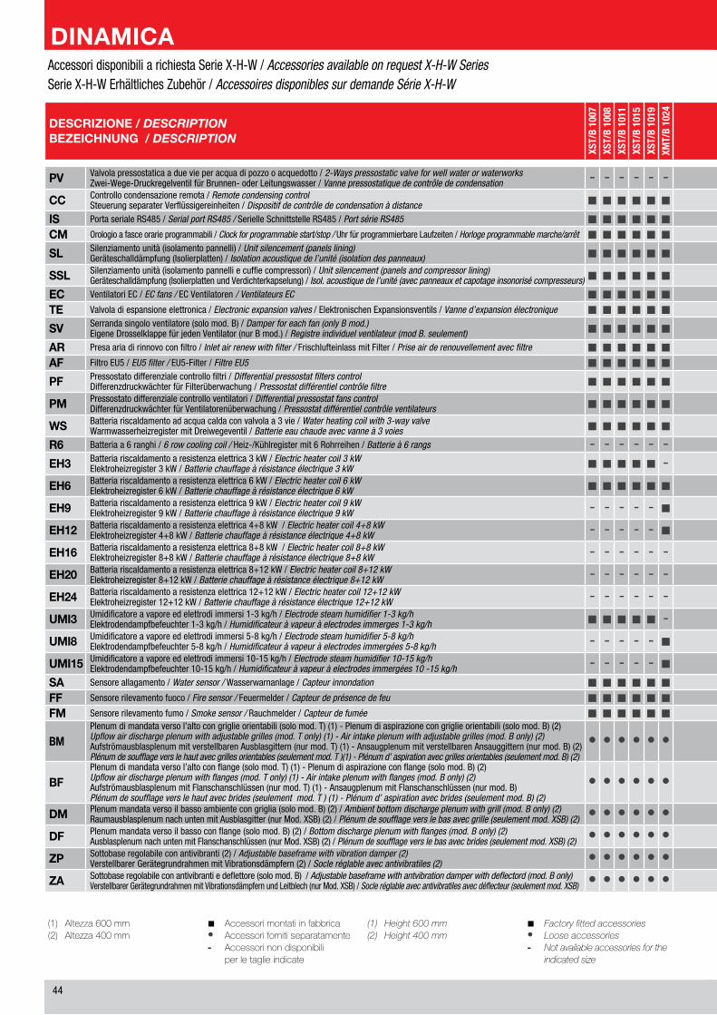
��
(1) Altezza600mm(2) Altezza400mm
■ Accessorimontatiinfabbrica• Accessorifornitiseparatamente- Accessorinondisponibili perletaglieindicate
(1) Height600mm(2) Height400mm
■ Factoryfittedaccessories• Looseaccessories- Notavailableaccessoriesforthe indicatedsize
DESCRIZIONE / DESCRIPTIONBEZEICHNUNG / DESCRIPTION
XST/
B 10
07XS
T/B
1008
XST/
B 10
11XS
T/B
1015
XST/
B 10
19XM
T/B
1024
XMT/
B 10
28XM
T/B
1033
XMT/
B 10
38XM
T/B
1049
XMT/
B 10
62XM
T/B
2029
XMT/
B 20
38XM
T/B
2049
XMT/
B 20
58XM
T/B
2069
XMT/
B 20
78XL
T/B
2096
XLT/
B 21
25
HST/
B 10
08HS
T/B
1009
HST/
B 10
12HS
T/B
1016
HST/
B 10
20HM
T/B
1025
HMT/
B 10
30HM
T/B
1036
HMT/
B 10
41HM
T/B
1053
HMT/
B 10
66HM
T/B
2031
HMT/
B 20
41HM
T/B
2055
HMT/
B 20
64HM
T/B
2074
HMT/
B 20
83HL
T/B
2104
HLT/
B 21
34
WST
/B 0
007
WST
/B 0
009
WST
/B 0
016
WM
T/B
0022
WM
T/B
0030
WM
T/B
0040
WM
T/B
0046
WM
T/B
0060
WLT
/B 0
076
WLT
/B 0
102
PV Valvola pressostatica a due vie per acqua di pozzo o acquedotto / 2-Ways pressostatic valve for well water or waterworksZwei-Wege-Druckregelventil für Brunnen- oder Leitungswasser / Vanne pressostatique de contrôle de condensation - - - - - - - - - - - - - - - - - - - ■ ■ ■ ■ ■ ■ ■ ■ ■ ■ ■ ■ ■ ■ ■ ■ ■ ■ ■ - - - - - - - - - -
CC Controllo condensazione remota / Remote condensing controlSteuerung separater Verflüssigereinheiten / Dispositif de contrôle de condensation à distance ■ ■ ■ ■ ■ ■ ■ ■ ■ ■ ■ ■ ■ ■ ■ ■ ■ ■ ■ - - - - - - - - - - - - - - - - - - - - - - - - - - - - -
IS Porta seriale RS��� / Serial port RS485 / Serielle Schnittstelle RS��� / Port série RS485 ■ ■ ■ ■ ■ ■ ■ ■ ■ ■ ■ ■ ■ ■ ■ ■ ■ ■ ■ ■ ■ ■ ■ ■ ■ ■ ■ ■ ■ ■ ■ ■ ■ ■ ■ ■ ■ ■ ■ ■ ■ ■ ■ ■ ■ ■ ■ ■CM Orologio a fasce orarie programmabili / Clock for programmable start/stop / Uhr für programmierbare Laufzeiten / Horloge programmable marche/arrêt ■ ■ ■ ■ ■ ■ ■ ■ ■ ■ ■ ■ ■ ■ ■ ■ ■ ■ ■ ■ ■ ■ ■ ■ ■ ■ ■ ■ ■ ■ ■ ■ ■ ■ ■ ■ ■ ■ ■ ■ ■ ■ ■ ■ ■ ■ ■ ■SL Silenziamento unità (isolamento pannelli) / Unit silencement (panels lining)
Geräteschalldämpfung (Isolierplatten) / Isolation acoustique de l’unité (isolation des panneaux) ■ ■ ■ ■ ■ ■ ■ ■ ■ ■ ■ ■ ■ ■ ■ ■ ■ ■ ■ ■ ■ ■ ■ ■ ■ ■ ■ ■ ■ ■ ■ ■ ■ ■ ■ ■ ■ ■ ■ ■ ■ ■ ■ ■ ■ ■ ■ ■SSL Silenziamento unità (isolamento pannelli e cuffie compressori) / Unit silencement (panels and compressor lining)
Geräteschalldämpfung (Isolierplatten und Verdichterkapselung) / Isol. acoustique de l’unité (avec panneaux et capotage insonorisé compresseurs)■ ■ ■ ■ ■ ■ ■ ■ ■ ■ ■ ■ ■ ■ ■ ■ ■ ■ ■ ■ ■ ■ ■ ■ ■ ■ ■ ■ ■ ■ ■ ■ ■ ■ ■ ■ ■ ■ - - - - - - - - - -EC Ventilatori EC / EC fans / EC Ventilatoren / Ventilateurs EC ■ ■ ■ ■ ■ ■ ■ ■ ■ ■ ■ ■ ■ ■ ■ ■ ■ ■ ■ ■ ■ ■ ■ ■ ■ ■ ■ ■ ■ ■ ■ ■ ■ ■ ■ ■ ■ ■ ■ ■ ■ ■ ■ ■ ■ ■ ■ ■TE Valvola di espansione elettronica / Electronic expansion valves / Elektronischen Expansionsventils / Vanne d’expansion électronique ■ ■ ■ ■ ■ ■ ■ ■ ■ ■ ■ ■ ■ ■ ■ ■ ■ ■ ■ ■ ■ ■ ■ ■ ■ ■ ■ ■ ■ ■ ■ ■ ■ ■ ■ ■ ■ ■ - - - - - - - - - -SV Serranda singolo ventilatore (solo mod. B) / Damper for each fan (only B mod.)
Eigene Drosselklappe für jeden Ventilator (nur B mod.) / Registre individuel ventilateur (mod B. seulement) ■ ■ ■ ■ ■ ■ ■ ■ ■ ■ ■ ■ ■ ■ ■ ■ ■ ■ ■ ■ ■ ■ ■ ■ ■ ■ ■ ■ ■ ■ ■ ■ ■ ■ ■ ■ ■ ■ ■ ■ ■ ■ ■ ■ ■ ■ ■ ■AR Presa aria di rinnovo con filtro / Inlet air renew with filter / Frischlufteinlass mit Filter / Prise air de renouvellement avec filtre ■ ■ ■ ■ ■ ■ ■ ■ ■ ■ ■ ■ ■ ■ ■ ■ ■ ■ ■ ■ ■ ■ ■ ■ ■ ■ ■ ■ ■ ■ ■ ■ ■ ■ ■ ■ ■ ■ ■ ■ ■ ■ ■ ■ ■ ■ ■ ■AF Filtro EU� / EU5 filter / EU�-Filter / Filtre EU5 ■ ■ ■ ■ ■ ■ ■ ■ ■ ■ ■ ■ ■ ■ ■ ■ ■ ■ ■ ■ ■ ■ ■ ■ ■ ■ ■ ■ ■ ■ ■ ■ ■ ■ ■ ■ ■ ■ ■ ■ ■ ■ ■ ■ ■ ■ ■ ■PF Pressostato differenziale controllo filtri / Differential pressostat filters control
Differenzdruckwächter für Filterüberwachung / Pressostat différentiel contrôle filtre ■ ■ ■ ■ ■ ■ ■ ■ ■ ■ ■ ■ ■ ■ ■ ■ ■ ■ ■ ■ ■ ■ ■ ■ ■ ■ ■ ■ ■ ■ ■ ■ ■ ■ ■ ■ ■ ■ ■ ■ ■ ■ ■ ■ ■ ■ ■ ■PM Pressostato differenziale controllo ventilatori / Differential pressostat fans control
Differenzdruckwächter für Ventilatorenüberwachung / Pressostat différentiel contrôle ventilateurs ■ ■ ■ ■ ■ ■ ■ ■ ■ ■ ■ ■ ■ ■ ■ ■ ■ ■ ■ ■ ■ ■ ■ ■ ■ ■ ■ ■ ■ ■ ■ ■ ■ ■ ■ ■ ■ ■ ■ ■ ■ ■ ■ ■ ■ ■ ■ ■WS Batteria riscaldamento ad acqua calda con valvola a � vie / Water heating coil with 3-way valve
Warmwasserheizregister mit Dreiwegeventil / Batterie eau chaude avec vanne à 3 voies ■ ■ ■ ■ ■ ■ ■ ■ ■ ■ ■ ■ ■ ■ ■ ■ ■ ■ ■ ■ ■ ■ ■ ■ ■ ■ ■ ■ ■ ■ ■ ■ ■ ■ ■ ■ ■ ■ ■ ■ ■ ■ ■ ■ ■ ■ ■ ■R6 Batteria a � ranghi / 6 row cooling coil / Heiz-/Kühlregister mit � Rohrreihen / Batterie à 6 rangs - - - - - - - - - - - - - - - - - - - - - - - - - - - - - - - - - - - - - - ■ ■ ■ ■ ■ ■ ■ ■ ■ ■EH3 Batteria riscaldamento a resistenza elettrica � kW / Electric heater coil 3 kW
Elektroheizregister � kW / Batterie chauffage à résistance électrique 3 kW ■ ■ ■ ■ ■ - - - - - - - - - - - - - - ■ ■ ■ ■ ■ - - - - - - - - - - - - - - ■ ■ ■ - - - - - - -EH6 Batteria riscaldamento a resistenza elettrica � kW / Electric heater coil 6 kW
Elektroheizregister � kW / Batterie chauffage à résistance électrique 6 kW ■ ■ ■ ■ ■ ■ ■ - - - - - - - - - - - - ■ ■ ■ ■ ■ ■ ■ - - - - - - - - - - - - ■ ■ ■ ■ - - - - - -EH9 Batteria riscaldamento a resistenza elettrica � kW / Electric heater coil 9 kW
Elektroheizregister � kW / Batterie chauffage à résistance électrique 9 kW - - - - - ■ ■ ■ ■ ■ ■ ■ ■ ■ ■ - - - - - - - - - ■ ■ ■ ■ ■ ■ ■ ■ ■ ■ - - - - - - - ■ ■ ■ ■ - - -EH12 Batteria riscaldamento a resistenza elettrica �+� kW / Electric heater coil 4+8 kW
Elektroheizregister �+� kW / Batterie chauffage à résistance électrique 4+8 kW - - - - - ■ ■ ■ ■ ■ ■ ■ ■ ■ ■ ■ ■ ■ ■ - - - - - ■ ■ ■ ■ ■ ■ ■ ■ ■ ■ ■ ■ ■ ■ - - - ■ ■ ■ ■ ■ ■ ■EH16 Batteria riscaldamento a resistenza elettrica �+� kW / Electric heater coil 8+8 kW
Elektroheizregister �+� kW / Batterie chauffage à résistance électrique 8+8 kW - - - - - - - ■ ■ ■ ■ ■ ■ ■ ■ ■ ■ ■ ■ - - - - - - - ■ ■ ■ ■ ■ ■ ■ ■ ■ ■ ■ ■ - - - - - ■ ■ ■ ■ ■EH20 Batteria riscaldamento a resistenza elettrica �+1� kW / Electric heater coil 8+12 kW
Elektroheizregister �+1� kW / Batterie chauffage à résistance électrique 8+12 kW - - - - - - - - - - - - - - - ■ ■ ■ ■ - - - - - - - - - - - - - - - ■ ■ ■ ■ - - - - - - ■ ■ ■ ■EH24 Batteria riscaldamento a resistenza elettrica 1�+1� kW / Electric heater coil 12+12 kW
Elektroheizregister 1�+1� kW / Batterie chauffage à résistance électrique 12+12 kW - - - - - - - - - - - - - - - ■ ■ ■ ■ - - - - - - - - - - - - - - - ■ ■ ■ ■ - - - - - - ■ ■ ■ ■UMI3 Umidificatore a vapore ed elettrodi immersi 1-� kg/h / Electrode steam humidifier 1-3 kg/h
Elektrodendampfbefeuchter 1-� kg/h / Humidificateur à vapeur à electrodes immerges 1-3 kg/h ■ ■ ■ ■ ■ - - - - - - - - - - - - - - ■ ■ ■ ■ ■ - - - - - - - - - - - - - - ■ ■ ■ - - - - - - -UMI8 Umidificatore a vapore ed elettrodi immersi �-� kg/h / Electrode steam humidifier 5-8 kg/h
Elektrodendampfbefeuchter �-� kg/h / Humidificateur à vapeur à electrodes immergées 5-8 kg/h - - - - - ■ ■ ■ ■ ■ ■ ■ ■ ■ ■ ■ ■ ■ ■ - - - - - ■ ■ ■ ■ ■ ■ ■ ■ ■ ■ ■ ■ ■ ■ - - - ■ ■ ■ ■ ■ ■ ■UMI15 Umidificatore a vapore ed elettrodi immersi 10-1� kg/h / Electrode steam humidifier 10-15 kg/h
Elektrodendampfbefeuchter 10-1� kg/h / Humidificateur à vapeur à electrodes immergées 10 -15 kg/h - - - - - ■ ■ ■ ■ ■ ■ ■ ■ ■ ■ ■ ■ ■ ■ - - - - - ■ ■ ■ ■ ■ ■ ■ ■ ■ ■ ■ ■ ■ ■ - - - ■ ■ ■ ■ ■ ■ ■SA Sensore allagamento / Water sensor / Wasserwarnanlage / Capteur innondation ■ ■ ■ ■ ■ ■ ■ ■ ■ ■ ■ ■ ■ ■ ■ ■ ■ ■ ■ ■ ■ ■ ■ ■ ■ ■ ■ ■ ■ ■ ■ ■ ■ ■ ■ ■ ■ ■ ■ ■ ■ ■ ■ ■ ■ ■ ■ ■FF Sensore rilevamento fuoco / Fire sensor / Feuermelder / Capteur de présence de feu ■ ■ ■ ■ ■ ■ ■ ■ ■ ■ ■ ■ ■ ■ ■ ■ ■ ■ ■ ■ ■ ■ ■ ■ ■ ■ ■ ■ ■ ■ ■ ■ ■ ■ ■ ■ ■ ■ ■ ■ ■ ■ ■ ■ ■ ■ ■ ■FM Sensore rilevamento fumo / Smoke sensor / Rauchmelder / Capteur de fumée ■ ■ ■ ■ ■ ■ ■ ■ ■ ■ ■ ■ ■ ■ ■ ■ ■ ■ ■ ■ ■ ■ ■ ■ ■ ■ ■ ■ ■ ■ ■ ■ ■ ■ ■ ■ ■ ■ ■ ■ ■ ■ ■ ■ ■ ■ ■ ■
BMPlenum di mandata verso l’alto con griglie orientabili (solo mod. T) (1) - Plenum di aspirazione con griglie orientabili (solo mod. B) (�)Upflow air discharge plenum with adjustable grilles (mod. T only) (1) - Air intake plenum with adjustable grilles (mod. B only) (2)Aufströmausblasplenum mit verstellbaren Ausblasgittern (nur mod. T) (1) - Ansaugplenum mit verstellbaren Ansauggittern (nur mod. B) (�)Plénum de soufflage vers le haut avec grilles orientables (seulement mod. T )(1) - Plénum d’ aspiration avec grilles orientables (seulement mod. B) (2)
• • • • • • • • • • • • • • • • • • • • • • • • • • • • • • • • • • • • • • • • • • • • • • • •
BFPlenum di mandata verso l’alto con flange (solo mod. T) (1) - Plenum di aspirazione con flange (solo mod. B) (�)Upflow air discharge plenum with flanges (mod. T only) (1) - Air intake plenum with flanges (mod. B only) (2)Aufströmausblasplenum mit Flanschanschlüssen (nur mod. T) (1) - Ansaugplenum mit Flanschanschlüssen (nur mod. B) Plénum de soufflage vers le haut avec brides (seulement mod. T ) (1) - Plénum d’ aspiration avec brides (seulement mod. B) (2)
• • • • • • • • • • • • • • • • • • • • • • • • • • • • • • • • • • • • • • • • • • • • • • • •
DM Plenum mandata verso il basso ambiente con griglia (solo mod. B) (�) / Ambient bottom discharge plenum with grill (mod. B only) (2)Raumausblasplenum nach unten mit Ausblasgitter (nur Mod. XSB) (�) / Plénum de soufflage vers le bas avec grille (seulement mod. XSB) (2) • • • • • • • • • • • • • • • • • • • • • • • • • • • • • • • • • • • • • • • • • • • • • • • •
DF Plenum mandata verso il basso con flange (solo mod. B) (�) / Bottom discharge plenum with flanges (mod. B only) (2)Ausblasplenum nach unten mit Flanschanschlüssen (nur Mod. XSB) (�) / Plénum de soufflage vers le bas avec brides (seulement mod. XSB) (2) • • • • • • • • • • • • • • • • • • • • • • • • • • • • • • • • • • • • • • • • • • • • • • • •
ZP Sottobase regolabile con antivibranti (�) / Adjustable baseframe with vibration damper (2)Verstellbarer Gerätegrundrahmen mit Vibrationsdämpfern (�) / Socle réglable avec antivibratiles (2) • • • • • • • • • • • • • • • • • • • • • • • • • • • • • • • • • • • • • • • • • • • • • • • •
ZA Sottobase regolabile con antivibranti e deflettore (solo mod. B) / Adjustable baseframe with antvibration damper with deflectord (mod. B only)Verstellbarer Gerätegrundrahmen mit Vibrationsdämpfern und Leitblech (nur Mod. XSB) / Socle réglable avec antivibratiles avec déflecteur (seulement mod. XSB) • • • • • • • • • • • • • • • • • • • • • • • • • • • • • • • • • • • • • • • • • • • • • • • •
Accessori disponibili a richiesta Serie X-H-W / Accessories available on request X-H-W SeriesSerie X-H-W Erhältliches Zubehör / Accessoires disponibles sur demande Série X-H-W
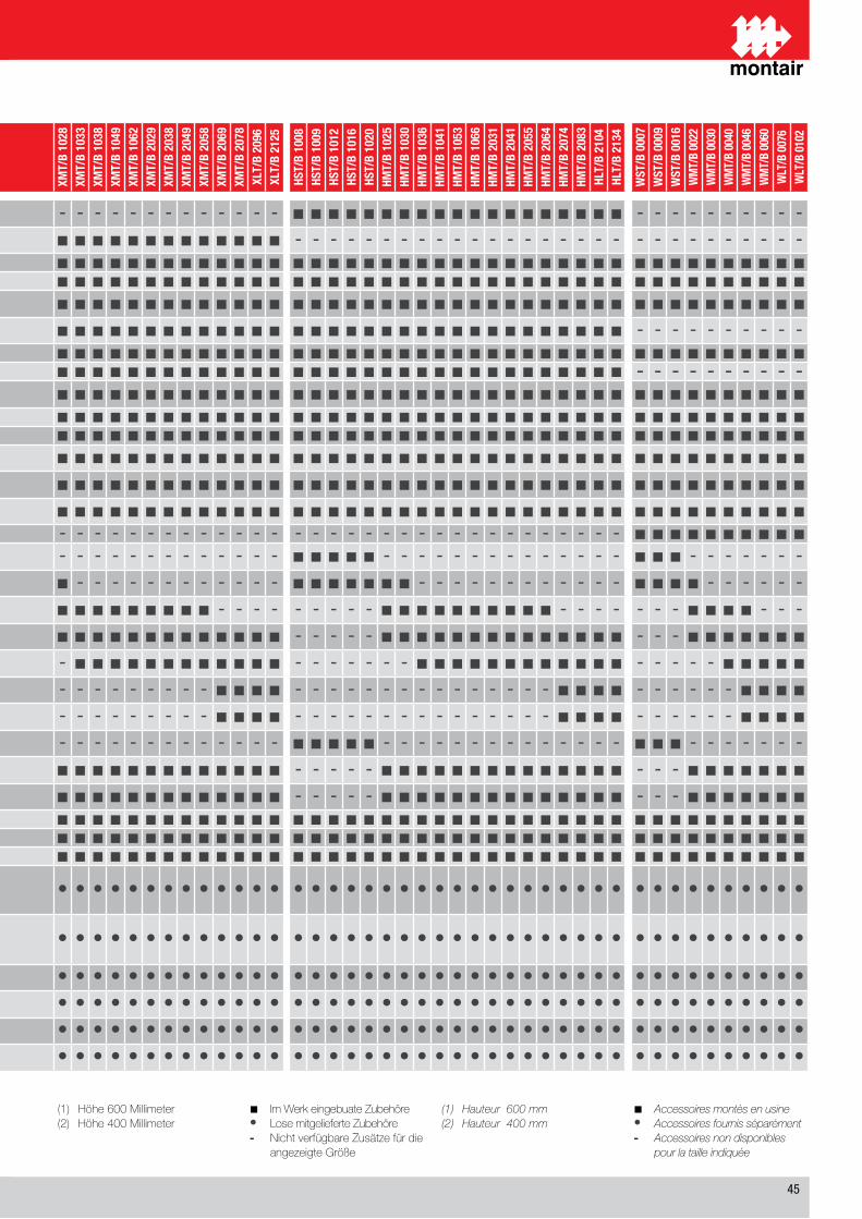
��
(1) Höhe600Millimeter(2) Höhe400Millimeter
■ ImWerkeingebuateZubehöre• LosemitgelieferteZubehöre- NichtverfügbareZusätzefürdie angezeigteGröße
(1) Hauteur600mm(2) Hauteur400mm
■ Accessoiresmontèsenusine• Accessoiresfournisséparément- Accessoiresnondisponibles pourlatailleindiquée
DESCRIZIONE / DESCRIPTIONBEZEICHNUNG / DESCRIPTION
XST/
B 10
07XS
T/B
1008
XST/
B 10
11XS
T/B
1015
XST/
B 10
19XM
T/B
1024
XMT/
B 10
28XM
T/B
1033
XMT/
B 10
38XM
T/B
1049
XMT/
B 10
62XM
T/B
2029
XMT/
B 20
38XM
T/B
2049
XMT/
B 20
58XM
T/B
2069
XMT/
B 20
78XL
T/B
2096
XLT/
B 21
25
HST/
B 10
08HS
T/B
1009
HST/
B 10
12HS
T/B
1016
HST/
B 10
20HM
T/B
1025
HMT/
B 10
30HM
T/B
1036
HMT/
B 10
41HM
T/B
1053
HMT/
B 10
66HM
T/B
2031
HMT/
B 20
41HM
T/B
2055
HMT/
B 20
64HM
T/B
2074
HMT/
B 20
83HL
T/B
2104
HLT/
B 21
34
WST
/B 0
007
WST
/B 0
009
WST
/B 0
016
WM
T/B
0022
WM
T/B
0030
WM
T/B
0040
WM
T/B
0046
WM
T/B
0060
WLT
/B 0
076
WLT
/B 0
102
PV Valvola pressostatica a due vie per acqua di pozzo o acquedotto / 2-Ways pressostatic valve for well water or waterworksZwei-Wege-Druckregelventil für Brunnen- oder Leitungswasser / Vanne pressostatique de contrôle de condensation - - - - - - - - - - - - - - - - - - - ■ ■ ■ ■ ■ ■ ■ ■ ■ ■ ■ ■ ■ ■ ■ ■ ■ ■ ■ - - - - - - - - - -
CC Controllo condensazione remota / Remote condensing controlSteuerung separater Verflüssigereinheiten / Dispositif de contrôle de condensation à distance ■ ■ ■ ■ ■ ■ ■ ■ ■ ■ ■ ■ ■ ■ ■ ■ ■ ■ ■ - - - - - - - - - - - - - - - - - - - - - - - - - - - - -
IS Porta seriale RS��� / Serial port RS485 / Serielle Schnittstelle RS��� / Port série RS485 ■ ■ ■ ■ ■ ■ ■ ■ ■ ■ ■ ■ ■ ■ ■ ■ ■ ■ ■ ■ ■ ■ ■ ■ ■ ■ ■ ■ ■ ■ ■ ■ ■ ■ ■ ■ ■ ■ ■ ■ ■ ■ ■ ■ ■ ■ ■ ■CM Orologio a fasce orarie programmabili / Clock for programmable start/stop / Uhr für programmierbare Laufzeiten / Horloge programmable marche/arrêt ■ ■ ■ ■ ■ ■ ■ ■ ■ ■ ■ ■ ■ ■ ■ ■ ■ ■ ■ ■ ■ ■ ■ ■ ■ ■ ■ ■ ■ ■ ■ ■ ■ ■ ■ ■ ■ ■ ■ ■ ■ ■ ■ ■ ■ ■ ■ ■SL Silenziamento unità (isolamento pannelli) / Unit silencement (panels lining)
Geräteschalldämpfung (Isolierplatten) / Isolation acoustique de l’unité (isolation des panneaux) ■ ■ ■ ■ ■ ■ ■ ■ ■ ■ ■ ■ ■ ■ ■ ■ ■ ■ ■ ■ ■ ■ ■ ■ ■ ■ ■ ■ ■ ■ ■ ■ ■ ■ ■ ■ ■ ■ ■ ■ ■ ■ ■ ■ ■ ■ ■ ■SSL Silenziamento unità (isolamento pannelli e cuffie compressori) / Unit silencement (panels and compressor lining)
Geräteschalldämpfung (Isolierplatten und Verdichterkapselung) / Isol. acoustique de l’unité (avec panneaux et capotage insonorisé compresseurs)■ ■ ■ ■ ■ ■ ■ ■ ■ ■ ■ ■ ■ ■ ■ ■ ■ ■ ■ ■ ■ ■ ■ ■ ■ ■ ■ ■ ■ ■ ■ ■ ■ ■ ■ ■ ■ ■ - - - - - - - - - -EC Ventilatori EC / EC fans / EC Ventilatoren / Ventilateurs EC ■ ■ ■ ■ ■ ■ ■ ■ ■ ■ ■ ■ ■ ■ ■ ■ ■ ■ ■ ■ ■ ■ ■ ■ ■ ■ ■ ■ ■ ■ ■ ■ ■ ■ ■ ■ ■ ■ ■ ■ ■ ■ ■ ■ ■ ■ ■ ■TE Valvola di espansione elettronica / Electronic expansion valves / Elektronischen Expansionsventils / Vanne d’expansion électronique ■ ■ ■ ■ ■ ■ ■ ■ ■ ■ ■ ■ ■ ■ ■ ■ ■ ■ ■ ■ ■ ■ ■ ■ ■ ■ ■ ■ ■ ■ ■ ■ ■ ■ ■ ■ ■ ■ - - - - - - - - - -SV Serranda singolo ventilatore (solo mod. B) / Damper for each fan (only B mod.)
Eigene Drosselklappe für jeden Ventilator (nur B mod.) / Registre individuel ventilateur (mod B. seulement) ■ ■ ■ ■ ■ ■ ■ ■ ■ ■ ■ ■ ■ ■ ■ ■ ■ ■ ■ ■ ■ ■ ■ ■ ■ ■ ■ ■ ■ ■ ■ ■ ■ ■ ■ ■ ■ ■ ■ ■ ■ ■ ■ ■ ■ ■ ■ ■AR Presa aria di rinnovo con filtro / Inlet air renew with filter / Frischlufteinlass mit Filter / Prise air de renouvellement avec filtre ■ ■ ■ ■ ■ ■ ■ ■ ■ ■ ■ ■ ■ ■ ■ ■ ■ ■ ■ ■ ■ ■ ■ ■ ■ ■ ■ ■ ■ ■ ■ ■ ■ ■ ■ ■ ■ ■ ■ ■ ■ ■ ■ ■ ■ ■ ■ ■AF Filtro EU� / EU5 filter / EU�-Filter / Filtre EU5 ■ ■ ■ ■ ■ ■ ■ ■ ■ ■ ■ ■ ■ ■ ■ ■ ■ ■ ■ ■ ■ ■ ■ ■ ■ ■ ■ ■ ■ ■ ■ ■ ■ ■ ■ ■ ■ ■ ■ ■ ■ ■ ■ ■ ■ ■ ■ ■PF Pressostato differenziale controllo filtri / Differential pressostat filters control
Differenzdruckwächter für Filterüberwachung / Pressostat différentiel contrôle filtre ■ ■ ■ ■ ■ ■ ■ ■ ■ ■ ■ ■ ■ ■ ■ ■ ■ ■ ■ ■ ■ ■ ■ ■ ■ ■ ■ ■ ■ ■ ■ ■ ■ ■ ■ ■ ■ ■ ■ ■ ■ ■ ■ ■ ■ ■ ■ ■PM Pressostato differenziale controllo ventilatori / Differential pressostat fans control
Differenzdruckwächter für Ventilatorenüberwachung / Pressostat différentiel contrôle ventilateurs ■ ■ ■ ■ ■ ■ ■ ■ ■ ■ ■ ■ ■ ■ ■ ■ ■ ■ ■ ■ ■ ■ ■ ■ ■ ■ ■ ■ ■ ■ ■ ■ ■ ■ ■ ■ ■ ■ ■ ■ ■ ■ ■ ■ ■ ■ ■ ■WS Batteria riscaldamento ad acqua calda con valvola a � vie / Water heating coil with 3-way valve
Warmwasserheizregister mit Dreiwegeventil / Batterie eau chaude avec vanne à 3 voies ■ ■ ■ ■ ■ ■ ■ ■ ■ ■ ■ ■ ■ ■ ■ ■ ■ ■ ■ ■ ■ ■ ■ ■ ■ ■ ■ ■ ■ ■ ■ ■ ■ ■ ■ ■ ■ ■ ■ ■ ■ ■ ■ ■ ■ ■ ■ ■R6 Batteria a � ranghi / 6 row cooling coil / Heiz-/Kühlregister mit � Rohrreihen / Batterie à 6 rangs - - - - - - - - - - - - - - - - - - - - - - - - - - - - - - - - - - - - - - ■ ■ ■ ■ ■ ■ ■ ■ ■ ■EH3 Batteria riscaldamento a resistenza elettrica � kW / Electric heater coil 3 kW
Elektroheizregister � kW / Batterie chauffage à résistance électrique 3 kW ■ ■ ■ ■ ■ - - - - - - - - - - - - - - ■ ■ ■ ■ ■ - - - - - - - - - - - - - - ■ ■ ■ - - - - - - -EH6 Batteria riscaldamento a resistenza elettrica � kW / Electric heater coil 6 kW
Elektroheizregister � kW / Batterie chauffage à résistance électrique 6 kW ■ ■ ■ ■ ■ ■ ■ - - - - - - - - - - - - ■ ■ ■ ■ ■ ■ ■ - - - - - - - - - - - - ■ ■ ■ ■ - - - - - -EH9 Batteria riscaldamento a resistenza elettrica � kW / Electric heater coil 9 kW
Elektroheizregister � kW / Batterie chauffage à résistance électrique 9 kW - - - - - ■ ■ ■ ■ ■ ■ ■ ■ ■ ■ - - - - - - - - - ■ ■ ■ ■ ■ ■ ■ ■ ■ ■ - - - - - - - ■ ■ ■ ■ - - -EH12 Batteria riscaldamento a resistenza elettrica �+� kW / Electric heater coil 4+8 kW
Elektroheizregister �+� kW / Batterie chauffage à résistance électrique 4+8 kW - - - - - ■ ■ ■ ■ ■ ■ ■ ■ ■ ■ ■ ■ ■ ■ - - - - - ■ ■ ■ ■ ■ ■ ■ ■ ■ ■ ■ ■ ■ ■ - - - ■ ■ ■ ■ ■ ■ ■EH16 Batteria riscaldamento a resistenza elettrica �+� kW / Electric heater coil 8+8 kW
Elektroheizregister �+� kW / Batterie chauffage à résistance électrique 8+8 kW - - - - - - - ■ ■ ■ ■ ■ ■ ■ ■ ■ ■ ■ ■ - - - - - - - ■ ■ ■ ■ ■ ■ ■ ■ ■ ■ ■ ■ - - - - - ■ ■ ■ ■ ■EH20 Batteria riscaldamento a resistenza elettrica �+1� kW / Electric heater coil 8+12 kW
Elektroheizregister �+1� kW / Batterie chauffage à résistance électrique 8+12 kW - - - - - - - - - - - - - - - ■ ■ ■ ■ - - - - - - - - - - - - - - - ■ ■ ■ ■ - - - - - - ■ ■ ■ ■EH24 Batteria riscaldamento a resistenza elettrica 1�+1� kW / Electric heater coil 12+12 kW
Elektroheizregister 1�+1� kW / Batterie chauffage à résistance électrique 12+12 kW - - - - - - - - - - - - - - - ■ ■ ■ ■ - - - - - - - - - - - - - - - ■ ■ ■ ■ - - - - - - ■ ■ ■ ■UMI3 Umidificatore a vapore ed elettrodi immersi 1-� kg/h / Electrode steam humidifier 1-3 kg/h
Elektrodendampfbefeuchter 1-� kg/h / Humidificateur à vapeur à electrodes immerges 1-3 kg/h ■ ■ ■ ■ ■ - - - - - - - - - - - - - - ■ ■ ■ ■ ■ - - - - - - - - - - - - - - ■ ■ ■ - - - - - - -UMI8 Umidificatore a vapore ed elettrodi immersi �-� kg/h / Electrode steam humidifier 5-8 kg/h
Elektrodendampfbefeuchter �-� kg/h / Humidificateur à vapeur à electrodes immergées 5-8 kg/h - - - - - ■ ■ ■ ■ ■ ■ ■ ■ ■ ■ ■ ■ ■ ■ - - - - - ■ ■ ■ ■ ■ ■ ■ ■ ■ ■ ■ ■ ■ ■ - - - ■ ■ ■ ■ ■ ■ ■UMI15 Umidificatore a vapore ed elettrodi immersi 10-1� kg/h / Electrode steam humidifier 10-15 kg/h
Elektrodendampfbefeuchter 10-1� kg/h / Humidificateur à vapeur à electrodes immergées 10 -15 kg/h - - - - - ■ ■ ■ ■ ■ ■ ■ ■ ■ ■ ■ ■ ■ ■ - - - - - ■ ■ ■ ■ ■ ■ ■ ■ ■ ■ ■ ■ ■ ■ - - - ■ ■ ■ ■ ■ ■ ■SA Sensore allagamento / Water sensor / Wasserwarnanlage / Capteur innondation ■ ■ ■ ■ ■ ■ ■ ■ ■ ■ ■ ■ ■ ■ ■ ■ ■ ■ ■ ■ ■ ■ ■ ■ ■ ■ ■ ■ ■ ■ ■ ■ ■ ■ ■ ■ ■ ■ ■ ■ ■ ■ ■ ■ ■ ■ ■ ■FF Sensore rilevamento fuoco / Fire sensor / Feuermelder / Capteur de présence de feu ■ ■ ■ ■ ■ ■ ■ ■ ■ ■ ■ ■ ■ ■ ■ ■ ■ ■ ■ ■ ■ ■ ■ ■ ■ ■ ■ ■ ■ ■ ■ ■ ■ ■ ■ ■ ■ ■ ■ ■ ■ ■ ■ ■ ■ ■ ■ ■FM Sensore rilevamento fumo / Smoke sensor / Rauchmelder / Capteur de fumée ■ ■ ■ ■ ■ ■ ■ ■ ■ ■ ■ ■ ■ ■ ■ ■ ■ ■ ■ ■ ■ ■ ■ ■ ■ ■ ■ ■ ■ ■ ■ ■ ■ ■ ■ ■ ■ ■ ■ ■ ■ ■ ■ ■ ■ ■ ■ ■
BMPlenum di mandata verso l’alto con griglie orientabili (solo mod. T) (1) - Plenum di aspirazione con griglie orientabili (solo mod. B) (�)Upflow air discharge plenum with adjustable grilles (mod. T only) (1) - Air intake plenum with adjustable grilles (mod. B only) (2)Aufströmausblasplenum mit verstellbaren Ausblasgittern (nur mod. T) (1) - Ansaugplenum mit verstellbaren Ansauggittern (nur mod. B) (�)Plénum de soufflage vers le haut avec grilles orientables (seulement mod. T )(1) - Plénum d’ aspiration avec grilles orientables (seulement mod. B) (2)
• • • • • • • • • • • • • • • • • • • • • • • • • • • • • • • • • • • • • • • • • • • • • • • •
BFPlenum di mandata verso l’alto con flange (solo mod. T) (1) - Plenum di aspirazione con flange (solo mod. B) (�)Upflow air discharge plenum with flanges (mod. T only) (1) - Air intake plenum with flanges (mod. B only) (2)Aufströmausblasplenum mit Flanschanschlüssen (nur mod. T) (1) - Ansaugplenum mit Flanschanschlüssen (nur mod. B) Plénum de soufflage vers le haut avec brides (seulement mod. T ) (1) - Plénum d’ aspiration avec brides (seulement mod. B) (2)
• • • • • • • • • • • • • • • • • • • • • • • • • • • • • • • • • • • • • • • • • • • • • • • •
DM Plenum mandata verso il basso ambiente con griglia (solo mod. B) (�) / Ambient bottom discharge plenum with grill (mod. B only) (2)Raumausblasplenum nach unten mit Ausblasgitter (nur Mod. XSB) (�) / Plénum de soufflage vers le bas avec grille (seulement mod. XSB) (2) • • • • • • • • • • • • • • • • • • • • • • • • • • • • • • • • • • • • • • • • • • • • • • • •
DF Plenum mandata verso il basso con flange (solo mod. B) (�) / Bottom discharge plenum with flanges (mod. B only) (2)Ausblasplenum nach unten mit Flanschanschlüssen (nur Mod. XSB) (�) / Plénum de soufflage vers le bas avec brides (seulement mod. XSB) (2) • • • • • • • • • • • • • • • • • • • • • • • • • • • • • • • • • • • • • • • • • • • • • • • •
ZP Sottobase regolabile con antivibranti (�) / Adjustable baseframe with vibration damper (2)Verstellbarer Gerätegrundrahmen mit Vibrationsdämpfern (�) / Socle réglable avec antivibratiles (2) • • • • • • • • • • • • • • • • • • • • • • • • • • • • • • • • • • • • • • • • • • • • • • • •
ZA Sottobase regolabile con antivibranti e deflettore (solo mod. B) / Adjustable baseframe with antvibration damper with deflectord (mod. B only)Verstellbarer Gerätegrundrahmen mit Vibrationsdämpfern und Leitblech (nur Mod. XSB) / Socle réglable avec antivibratiles avec déflecteur (seulement mod. XSB) • • • • • • • • • • • • • • • • • • • • • • • • • • • • • • • • • • • • • • • • • • • • • • • •
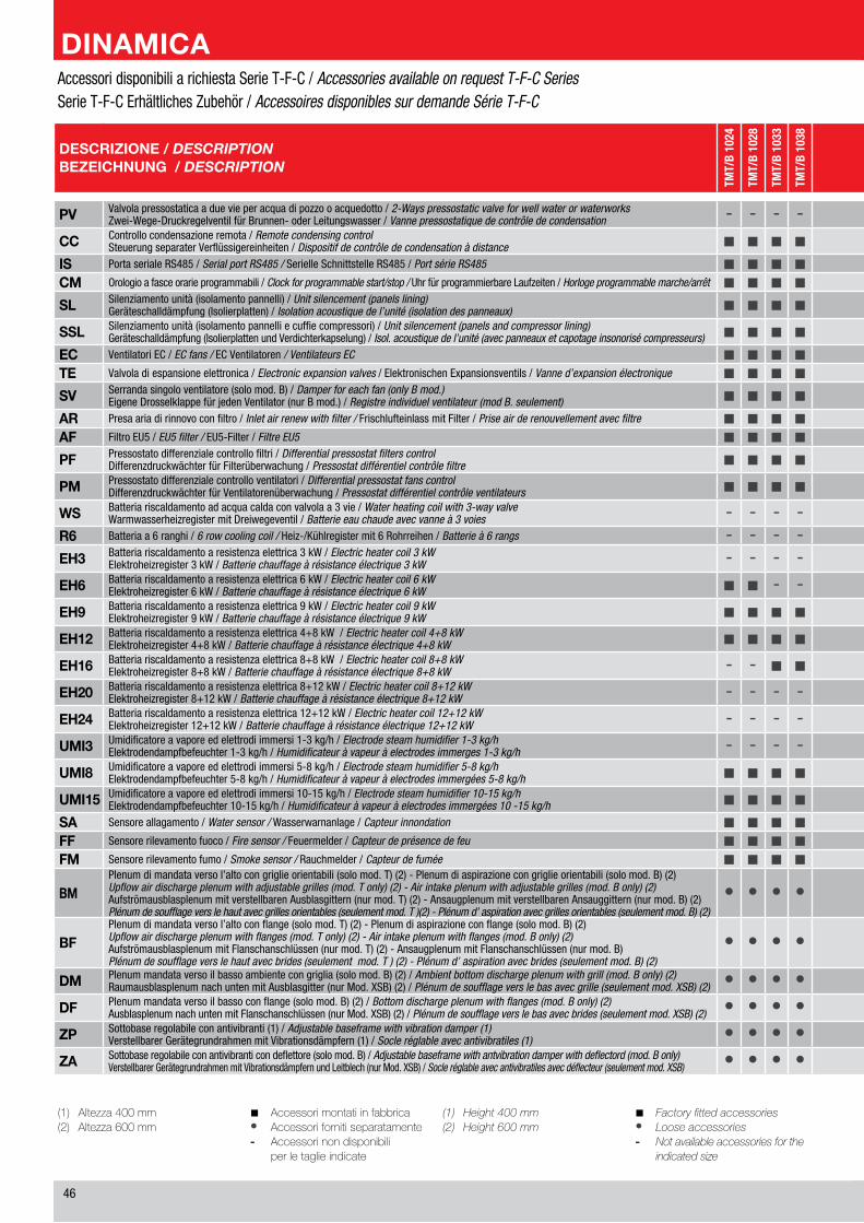
��
(1) Altezza400mm(2) Altezza600mm
■ Accessorimontatiinfabbrica• Accessorifornitiseparatamente- Accessorinondisponibili perletaglieindicate
(1) Height400mm(2) Height600mm
■ Factoryfittedaccessories• Looseaccessories- Notavailableaccessoriesforthe indicatedsize
DESCRIZIONE / DESCRIPTIONBEZEICHNUNG / DESCRIPTION
TMT/
B 10
24
TMT/
B 10
28
TMT/
B 10
33
TMT/
B 10
38
TMT/
B 10
49
TMT/
B 10
62
TMT/
B 20
29
TMT/
B 20
38
TMT/
B 20
49
TMT/
B 20
58
TMT/
B 20
69
TMT/
B 20
78
TLT/
B 20
96
TLT/
B 21
25
FMT/
B 10
25
FMT/
B 10
30
FMT/
B 10
36
FMT/
B 10
41
FMT/
B 10
53
FMT/
B 10
66
FMT/
B 20
31
FMT/
B 20
41
FMT/
B 20
55
FMT/
B 20
64
FMT/
B 20
74
FMT/
B 20
83
FLT/
B 21
04
FLT/
B 21
34
CMT/
B 00
22
CMT/
B 00
30
CMT/
B 00
40
CMT/
B 00
46
CMT/
B 00
60
CLT/
B 00
76
CLT/
B 01
02
PV Valvola pressostatica a due vie per acqua di pozzo o acquedotto / 2-Ways pressostatic valve for well water or waterworksZwei-Wege-Druckregelventil für Brunnen- oder Leitungswasser / Vanne pressostatique de contrôle de condensation - - - - - - - - - - - - - - - - - - - - - - - - - - - - - - - - - - -
CC Controllo condensazione remota / Remote condensing controlSteuerung separater Verflüssigereinheiten / Dispositif de contrôle de condensation à distance ■ ■ ■ ■ ■ ■ ■ ■ ■ ■ ■ ■ ■ ■ - - - - - - - - - - - - - - - - - - - - -
IS Porta seriale RS��� / Serial port RS485 / Serielle Schnittstelle RS��� / Port série RS485 ■ ■ ■ ■ ■ ■ ■ ■ ■ ■ ■ ■ ■ ■ ■ ■ ■ ■ ■ ■ ■ ■ ■ ■ ■ ■ ■ ■ ■ ■ ■ ■ ■ ■ ■CM Orologio a fasce orarie programmabili / Clock for programmable start/stop / Uhr für programmierbare Laufzeiten / Horloge programmable marche/arrêt ■ ■ ■ ■ ■ ■ ■ ■ ■ ■ ■ ■ ■ ■ ■ ■ ■ ■ ■ ■ ■ ■ ■ ■ ■ ■ ■ ■ ■ ■ ■ ■ ■ ■ ■SL Silenziamento unità (isolamento pannelli) / Unit silencement (panels lining)
Geräteschalldämpfung (Isolierplatten) / Isolation acoustique de l’unité (isolation des panneaux) ■ ■ ■ ■ ■ ■ ■ ■ ■ ■ ■ ■ ■ ■ ■ ■ ■ ■ ■ ■ ■ ■ ■ ■ ■ ■ ■ ■ ■ ■ ■ ■ ■ ■ ■SSL Silenziamento unità (isolamento pannelli e cuffie compressori) / Unit silencement (panels and compressor lining)
Geräteschalldämpfung (Isolierplatten und Verdichterkapselung) / Isol. acoustique de l’unité (avec panneaux et capotage insonorisé compresseurs) ■ ■ ■ ■ ■ ■ ■ ■ ■ ■ ■ ■ ■ ■ ■ ■ ■ ■ ■ ■ ■ ■ ■ ■ ■ ■ ■ ■ - - - - - - -EC Ventilatori EC / EC fans / EC Ventilatoren / Ventilateurs EC ■ ■ ■ ■ ■ ■ ■ ■ ■ ■ ■ ■ ■ ■ ■ ■ ■ ■ ■ ■ ■ ■ ■ ■ ■ ■ ■ ■ ■ ■ ■ ■ ■ ■ ■TE Valvola di espansione elettronica / Electronic expansion valves / Elektronischen Expansionsventils / Vanne d’expansion électronique ■ ■ ■ ■ ■ ■ ■ ■ ■ ■ ■ ■ ■ ■ ■ ■ ■ ■ ■ ■ ■ ■ ■ ■ ■ ■ ■ ■ - - - - - - -SV Serranda singolo ventilatore (solo mod. B) / Damper for each fan (only B mod.)
Eigene Drosselklappe für jeden Ventilator (nur B mod.) / Registre individuel ventilateur (mod B. seulement) ■ ■ ■ ■ ■ ■ ■ ■ ■ ■ ■ ■ ■ ■ ■ ■ ■ ■ ■ ■ ■ ■ ■ ■ ■ ■ ■ ■ ■ ■ ■ ■ ■ ■ ■AR Presa aria di rinnovo con filtro / Inlet air renew with filter / Frischlufteinlass mit Filter / Prise air de renouvellement avec filtre ■ ■ ■ ■ ■ ■ ■ ■ ■ ■ ■ ■ ■ ■ ■ ■ ■ ■ ■ ■ ■ ■ ■ ■ ■ ■ ■ ■ ■ ■ ■ ■ ■ ■ ■AF Filtro EU� / EU5 filter / EU�-Filter / Filtre EU5 ■ ■ ■ ■ ■ ■ ■ ■ ■ ■ ■ ■ ■ ■ ■ ■ ■ ■ ■ ■ ■ ■ ■ ■ ■ ■ ■ ■ ■ ■ ■ ■ ■ ■ ■PF Pressostato differenziale controllo filtri / Differential pressostat filters control
Differenzdruckwächter für Filterüberwachung / Pressostat différentiel contrôle filtre ■ ■ ■ ■ ■ ■ ■ ■ ■ ■ ■ ■ ■ ■ ■ ■ ■ ■ ■ ■ ■ ■ ■ ■ ■ ■ ■ ■ ■ ■ ■ ■ ■ ■ ■PM Pressostato differenziale controllo ventilatori / Differential pressostat fans control
Differenzdruckwächter für Ventilatorenüberwachung / Pressostat différentiel contrôle ventilateurs ■ ■ ■ ■ ■ ■ ■ ■ ■ ■ ■ ■ ■ ■ ■ ■ ■ ■ ■ ■ ■ ■ ■ ■ ■ ■ ■ ■ ■ ■ ■ ■ ■ ■ ■WS Batteria riscaldamento ad acqua calda con valvola a � vie / Water heating coil with 3-way valve
Warmwasserheizregister mit Dreiwegeventil / Batterie eau chaude avec vanne à 3 voies - - - - - - - - - - - - - - - - - - - - - - - - - - - - - - - - - - -R6 Batteria a � ranghi / 6 row cooling coil / Heiz-/Kühlregister mit � Rohrreihen / Batterie à 6 rangs - - - - - - - - - - - - - - - - - - - - - - - - - - - - - - - - - - -EH3 Batteria riscaldamento a resistenza elettrica � kW / Electric heater coil 3 kW
Elektroheizregister � kW / Batterie chauffage à résistance électrique 3 kW - - - - - - - - - - - - - - - - - - - - - - - - - - - - - - - - - - -EH6 Batteria riscaldamento a resistenza elettrica � kW / Electric heater coil 6 kW
Elektroheizregister � kW / Batterie chauffage à résistance électrique 6 kW ■ ■ - - - - - - - - - - - - ■ ■ - - - - - - - - - - - - ■ - - - - - -EH9 Batteria riscaldamento a resistenza elettrica � kW / Electric heater coil 9 kW
Elektroheizregister � kW / Batterie chauffage à résistance électrique 9 kW ■ ■ ■ ■ ■ ■ ■ ■ ■ ■ - - - - ■ ■ ■ ■ ■ ■ ■ ■ ■ ■ - - - - ■ ■ ■ ■ - - -EH12 Batteria riscaldamento a resistenza elettrica �+� kW / Electric heater coil 4+8 kW
Elektroheizregister �+� kW / Batterie chauffage à résistance électrique 4+8 kW ■ ■ ■ ■ ■ ■ ■ ■ ■ ■ ■ ■ ■ ■ ■ ■ ■ ■ ■ ■ ■ ■ ■ ■ ■ ■ ■ ■ ■ ■ ■ ■ ■ ■ ■EH16 Batteria riscaldamento a resistenza elettrica �+� kW / Electric heater coil 8+8 kW
Elektroheizregister �+� kW / Batterie chauffage à résistance électrique 8+8 kW - - ■ ■ ■ ■ ■ ■ ■ ■ ■ ■ ■ ■ - - ■ ■ ■ ■ ■ ■ ■ ■ ■ ■ ■ ■ - - ■ ■ ■ ■ ■EH20 Batteria riscaldamento a resistenza elettrica �+1� kW / Electric heater coil 8+12 kW
Elektroheizregister �+1� kW / Batterie chauffage à résistance électrique 8+12 kW - - - - - - - - - - ■ ■ ■ ■ - - - - - - - - - - ■ ■ ■ ■ - - - ■ ■ ■ ■EH24 Batteria riscaldamento a resistenza elettrica 1�+1� kW / Electric heater coil 12+12 kW
Elektroheizregister 1�+1� kW / Batterie chauffage à résistance électrique 12+12 kW - - - - - - - - - - ■ ■ ■ ■ - - - - - - - - - - ■ ■ ■ ■ - - - ■ ■ ■ ■UMI3 Umidificatore a vapore ed elettrodi immersi 1-� kg/h / Electrode steam humidifier 1-3 kg/h
Elektrodendampfbefeuchter 1-� kg/h / Humidificateur à vapeur à electrodes immerges 1-3 kg/h - - - - - - - - - - - - - - - - - - - - - - - - - - - - - - - - - - -UMI8 Umidificatore a vapore ed elettrodi immersi �-� kg/h / Electrode steam humidifier 5-8 kg/h
Elektrodendampfbefeuchter �-� kg/h / Humidificateur à vapeur à electrodes immergées 5-8 kg/h ■ ■ ■ ■ ■ ■ ■ ■ ■ ■ ■ ■ ■ ■ ■ ■ ■ ■ ■ ■ ■ ■ ■ ■ ■ ■ ■ ■ ■ ■ ■ ■ ■ ■ ■UMI15 Umidificatore a vapore ed elettrodi immersi 10-1� kg/h / Electrode steam humidifier 10-15 kg/h
Elektrodendampfbefeuchter 10-1� kg/h / Humidificateur à vapeur à electrodes immergées 10 -15 kg/h ■ ■ ■ ■ ■ ■ ■ ■ ■ ■ ■ ■ ■ ■ ■ ■ ■ ■ ■ ■ ■ ■ ■ ■ ■ ■ ■ ■ ■ ■ ■ ■ ■ ■ ■SA Sensore allagamento / Water sensor / Wasserwarnanlage / Capteur innondation ■ ■ ■ ■ ■ ■ ■ ■ ■ ■ ■ ■ ■ ■ ■ ■ ■ ■ ■ ■ ■ ■ ■ ■ ■ ■ ■ ■ ■ ■ ■ ■ ■ ■ ■FF Sensore rilevamento fuoco / Fire sensor / Feuermelder / Capteur de présence de feu ■ ■ ■ ■ ■ ■ ■ ■ ■ ■ ■ ■ ■ ■ ■ ■ ■ ■ ■ ■ ■ ■ ■ ■ ■ ■ ■ ■ ■ ■ ■ ■ ■ ■ ■FM Sensore rilevamento fumo / Smoke sensor / Rauchmelder / Capteur de fumée ■ ■ ■ ■ ■ ■ ■ ■ ■ ■ ■ ■ ■ ■ ■ ■ ■ ■ ■ ■ ■ ■ ■ ■ ■ ■ ■ ■ ■ ■ ■ ■ ■ ■ ■
BMPlenum di mandata verso l’alto con griglie orientabili (solo mod. T) (�) - Plenum di aspirazione con griglie orientabili (solo mod. B) (�)Upflow air discharge plenum with adjustable grilles (mod. T only) (2) - Air intake plenum with adjustable grilles (mod. B only) (2)Aufströmausblasplenum mit verstellbaren Ausblasgittern (nur mod. T) (�) - Ansaugplenum mit verstellbaren Ansauggittern (nur mod. B) (�)Plénum de soufflage vers le haut avec grilles orientables (seulement mod. T )(2) - Plénum d’ aspiration avec grilles orientables (seulement mod. B) (2)
• • • • • • • • • • • • • • • • • • • • • • • • • • • • • • • • • • •
BFPlenum di mandata verso l’alto con flange (solo mod. T) (�) - Plenum di aspirazione con flange (solo mod. B) (�)Upflow air discharge plenum with flanges (mod. T only) (2) - Air intake plenum with flanges (mod. B only) (2)Aufströmausblasplenum mit Flanschanschlüssen (nur mod. T) (�) - Ansaugplenum mit Flanschanschlüssen (nur mod. B) Plénum de soufflage vers le haut avec brides (seulement mod. T ) (2) - Plénum d’ aspiration avec brides (seulement mod. B) (2)
• • • • • • • • • • • • • • • • • • • • • • • • • • • • • • • • • • •
DM Plenum mandata verso il basso ambiente con griglia (solo mod. B) (�) / Ambient bottom discharge plenum with grill (mod. B only) (2)Raumausblasplenum nach unten mit Ausblasgitter (nur Mod. XSB) (�) / Plénum de soufflage vers le bas avec grille (seulement mod. XSB) (2) • • • • • • • • • • • • • • • • • • • • • • • • • • • • • • • • • • •
DF Plenum mandata verso il basso con flange (solo mod. B) (�) / Bottom discharge plenum with flanges (mod. B only) (2)Ausblasplenum nach unten mit Flanschanschlüssen (nur Mod. XSB) (�) / Plénum de soufflage vers le bas avec brides (seulement mod. XSB) (2) • • • • • • • • • • • • • • • • • • • • • • • • • • • • • • • • • • •
ZP Sottobase regolabile con antivibranti (1) / Adjustable baseframe with vibration damper (1)Verstellbarer Gerätegrundrahmen mit Vibrationsdämpfern (1) / Socle réglable avec antivibratiles (1) • • • • • • • • • • • • • • • • • • • • • • • • • • • • • • • • • • •
ZA Sottobase regolabile con antivibranti con deflettore (solo mod. B) / Adjustable baseframe with antvibration damper with deflectord (mod. B only)Verstellbarer Gerätegrundrahmen mit Vibrationsdämpfern und Leitblech (nur Mod. XSB) / Socle réglable avec antivibratiles avec déflecteur (seulement mod. XSB) • • • • • • • • • • • • • • • • • • • • • • • • • • • • • • • • • • •
Accessori disponibili a richiesta Serie T-F-C / Accessories available on request T-F-C SeriesSerie T-F-C Erhältliches Zubehör / Accessoires disponibles sur demande Série T-F-C
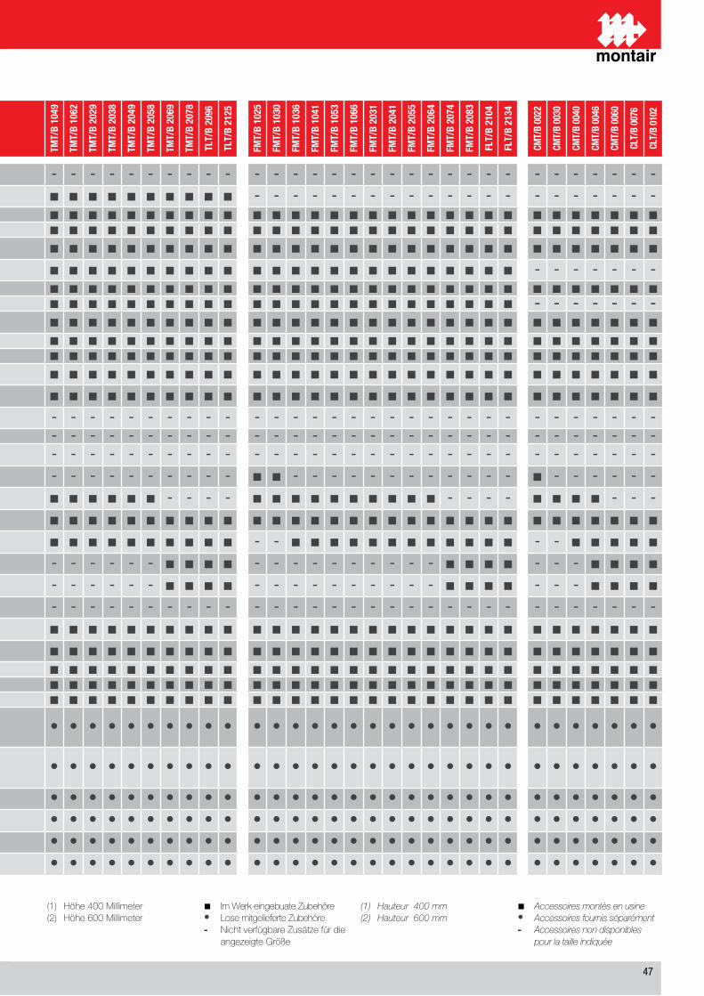
��
(1) Höhe400Millimeter(2) Höhe600Millimeter
■ ImWerkeingebuateZubehöre• LosemitgelieferteZubehöre- NichtverfügbareZusätzefürdie angezeigteGröße
(1) Hauteur400mm(2) Hauteur600mm
■ Accessoiresmontèsenusine• Accessoiresfournisséparément- Accessoiresnondisponibles pourlatailleindiquée
DESCRIZIONE / DESCRIPTIONBEZEICHNUNG / DESCRIPTION
TMT/
B 10
24
TMT/
B 10
28
TMT/
B 10
33
TMT/
B 10
38
TMT/
B 10
49
TMT/
B 10
62
TMT/
B 20
29
TMT/
B 20
38
TMT/
B 20
49
TMT/
B 20
58
TMT/
B 20
69
TMT/
B 20
78
TLT/
B 20
96
TLT/
B 21
25
FMT/
B 10
25
FMT/
B 10
30
FMT/
B 10
36
FMT/
B 10
41
FMT/
B 10
53
FMT/
B 10
66
FMT/
B 20
31
FMT/
B 20
41
FMT/
B 20
55
FMT/
B 20
64
FMT/
B 20
74
FMT/
B 20
83
FLT/
B 21
04
FLT/
B 21
34
CMT/
B 00
22
CMT/
B 00
30
CMT/
B 00
40
CMT/
B 00
46
CMT/
B 00
60
CLT/
B 00
76
CLT/
B 01
02
PV Valvola pressostatica a due vie per acqua di pozzo o acquedotto / 2-Ways pressostatic valve for well water or waterworksZwei-Wege-Druckregelventil für Brunnen- oder Leitungswasser / Vanne pressostatique de contrôle de condensation - - - - - - - - - - - - - - - - - - - - - - - - - - - - - - - - - - -
CC Controllo condensazione remota / Remote condensing controlSteuerung separater Verflüssigereinheiten / Dispositif de contrôle de condensation à distance ■ ■ ■ ■ ■ ■ ■ ■ ■ ■ ■ ■ ■ ■ - - - - - - - - - - - - - - - - - - - - -
IS Porta seriale RS��� / Serial port RS485 / Serielle Schnittstelle RS��� / Port série RS485 ■ ■ ■ ■ ■ ■ ■ ■ ■ ■ ■ ■ ■ ■ ■ ■ ■ ■ ■ ■ ■ ■ ■ ■ ■ ■ ■ ■ ■ ■ ■ ■ ■ ■ ■CM Orologio a fasce orarie programmabili / Clock for programmable start/stop / Uhr für programmierbare Laufzeiten / Horloge programmable marche/arrêt ■ ■ ■ ■ ■ ■ ■ ■ ■ ■ ■ ■ ■ ■ ■ ■ ■ ■ ■ ■ ■ ■ ■ ■ ■ ■ ■ ■ ■ ■ ■ ■ ■ ■ ■SL Silenziamento unità (isolamento pannelli) / Unit silencement (panels lining)
Geräteschalldämpfung (Isolierplatten) / Isolation acoustique de l’unité (isolation des panneaux) ■ ■ ■ ■ ■ ■ ■ ■ ■ ■ ■ ■ ■ ■ ■ ■ ■ ■ ■ ■ ■ ■ ■ ■ ■ ■ ■ ■ ■ ■ ■ ■ ■ ■ ■SSL Silenziamento unità (isolamento pannelli e cuffie compressori) / Unit silencement (panels and compressor lining)
Geräteschalldämpfung (Isolierplatten und Verdichterkapselung) / Isol. acoustique de l’unité (avec panneaux et capotage insonorisé compresseurs) ■ ■ ■ ■ ■ ■ ■ ■ ■ ■ ■ ■ ■ ■ ■ ■ ■ ■ ■ ■ ■ ■ ■ ■ ■ ■ ■ ■ - - - - - - -EC Ventilatori EC / EC fans / EC Ventilatoren / Ventilateurs EC ■ ■ ■ ■ ■ ■ ■ ■ ■ ■ ■ ■ ■ ■ ■ ■ ■ ■ ■ ■ ■ ■ ■ ■ ■ ■ ■ ■ ■ ■ ■ ■ ■ ■ ■TE Valvola di espansione elettronica / Electronic expansion valves / Elektronischen Expansionsventils / Vanne d’expansion électronique ■ ■ ■ ■ ■ ■ ■ ■ ■ ■ ■ ■ ■ ■ ■ ■ ■ ■ ■ ■ ■ ■ ■ ■ ■ ■ ■ ■ - - - - - - -SV Serranda singolo ventilatore (solo mod. B) / Damper for each fan (only B mod.)
Eigene Drosselklappe für jeden Ventilator (nur B mod.) / Registre individuel ventilateur (mod B. seulement) ■ ■ ■ ■ ■ ■ ■ ■ ■ ■ ■ ■ ■ ■ ■ ■ ■ ■ ■ ■ ■ ■ ■ ■ ■ ■ ■ ■ ■ ■ ■ ■ ■ ■ ■AR Presa aria di rinnovo con filtro / Inlet air renew with filter / Frischlufteinlass mit Filter / Prise air de renouvellement avec filtre ■ ■ ■ ■ ■ ■ ■ ■ ■ ■ ■ ■ ■ ■ ■ ■ ■ ■ ■ ■ ■ ■ ■ ■ ■ ■ ■ ■ ■ ■ ■ ■ ■ ■ ■AF Filtro EU� / EU5 filter / EU�-Filter / Filtre EU5 ■ ■ ■ ■ ■ ■ ■ ■ ■ ■ ■ ■ ■ ■ ■ ■ ■ ■ ■ ■ ■ ■ ■ ■ ■ ■ ■ ■ ■ ■ ■ ■ ■ ■ ■PF Pressostato differenziale controllo filtri / Differential pressostat filters control
Differenzdruckwächter für Filterüberwachung / Pressostat différentiel contrôle filtre ■ ■ ■ ■ ■ ■ ■ ■ ■ ■ ■ ■ ■ ■ ■ ■ ■ ■ ■ ■ ■ ■ ■ ■ ■ ■ ■ ■ ■ ■ ■ ■ ■ ■ ■PM Pressostato differenziale controllo ventilatori / Differential pressostat fans control
Differenzdruckwächter für Ventilatorenüberwachung / Pressostat différentiel contrôle ventilateurs ■ ■ ■ ■ ■ ■ ■ ■ ■ ■ ■ ■ ■ ■ ■ ■ ■ ■ ■ ■ ■ ■ ■ ■ ■ ■ ■ ■ ■ ■ ■ ■ ■ ■ ■WS Batteria riscaldamento ad acqua calda con valvola a � vie / Water heating coil with 3-way valve
Warmwasserheizregister mit Dreiwegeventil / Batterie eau chaude avec vanne à 3 voies - - - - - - - - - - - - - - - - - - - - - - - - - - - - - - - - - - -R6 Batteria a � ranghi / 6 row cooling coil / Heiz-/Kühlregister mit � Rohrreihen / Batterie à 6 rangs - - - - - - - - - - - - - - - - - - - - - - - - - - - - - - - - - - -EH3 Batteria riscaldamento a resistenza elettrica � kW / Electric heater coil 3 kW
Elektroheizregister � kW / Batterie chauffage à résistance électrique 3 kW - - - - - - - - - - - - - - - - - - - - - - - - - - - - - - - - - - -EH6 Batteria riscaldamento a resistenza elettrica � kW / Electric heater coil 6 kW
Elektroheizregister � kW / Batterie chauffage à résistance électrique 6 kW ■ ■ - - - - - - - - - - - - ■ ■ - - - - - - - - - - - - ■ - - - - - -EH9 Batteria riscaldamento a resistenza elettrica � kW / Electric heater coil 9 kW
Elektroheizregister � kW / Batterie chauffage à résistance électrique 9 kW ■ ■ ■ ■ ■ ■ ■ ■ ■ ■ - - - - ■ ■ ■ ■ ■ ■ ■ ■ ■ ■ - - - - ■ ■ ■ ■ - - -EH12 Batteria riscaldamento a resistenza elettrica �+� kW / Electric heater coil 4+8 kW
Elektroheizregister �+� kW / Batterie chauffage à résistance électrique 4+8 kW ■ ■ ■ ■ ■ ■ ■ ■ ■ ■ ■ ■ ■ ■ ■ ■ ■ ■ ■ ■ ■ ■ ■ ■ ■ ■ ■ ■ ■ ■ ■ ■ ■ ■ ■EH16 Batteria riscaldamento a resistenza elettrica �+� kW / Electric heater coil 8+8 kW
Elektroheizregister �+� kW / Batterie chauffage à résistance électrique 8+8 kW - - ■ ■ ■ ■ ■ ■ ■ ■ ■ ■ ■ ■ - - ■ ■ ■ ■ ■ ■ ■ ■ ■ ■ ■ ■ - - ■ ■ ■ ■ ■EH20 Batteria riscaldamento a resistenza elettrica �+1� kW / Electric heater coil 8+12 kW
Elektroheizregister �+1� kW / Batterie chauffage à résistance électrique 8+12 kW - - - - - - - - - - ■ ■ ■ ■ - - - - - - - - - - ■ ■ ■ ■ - - - ■ ■ ■ ■EH24 Batteria riscaldamento a resistenza elettrica 1�+1� kW / Electric heater coil 12+12 kW
Elektroheizregister 1�+1� kW / Batterie chauffage à résistance électrique 12+12 kW - - - - - - - - - - ■ ■ ■ ■ - - - - - - - - - - ■ ■ ■ ■ - - - ■ ■ ■ ■UMI3 Umidificatore a vapore ed elettrodi immersi 1-� kg/h / Electrode steam humidifier 1-3 kg/h
Elektrodendampfbefeuchter 1-� kg/h / Humidificateur à vapeur à electrodes immerges 1-3 kg/h - - - - - - - - - - - - - - - - - - - - - - - - - - - - - - - - - - -UMI8 Umidificatore a vapore ed elettrodi immersi �-� kg/h / Electrode steam humidifier 5-8 kg/h
Elektrodendampfbefeuchter �-� kg/h / Humidificateur à vapeur à electrodes immergées 5-8 kg/h ■ ■ ■ ■ ■ ■ ■ ■ ■ ■ ■ ■ ■ ■ ■ ■ ■ ■ ■ ■ ■ ■ ■ ■ ■ ■ ■ ■ ■ ■ ■ ■ ■ ■ ■UMI15 Umidificatore a vapore ed elettrodi immersi 10-1� kg/h / Electrode steam humidifier 10-15 kg/h
Elektrodendampfbefeuchter 10-1� kg/h / Humidificateur à vapeur à electrodes immergées 10 -15 kg/h ■ ■ ■ ■ ■ ■ ■ ■ ■ ■ ■ ■ ■ ■ ■ ■ ■ ■ ■ ■ ■ ■ ■ ■ ■ ■ ■ ■ ■ ■ ■ ■ ■ ■ ■SA Sensore allagamento / Water sensor / Wasserwarnanlage / Capteur innondation ■ ■ ■ ■ ■ ■ ■ ■ ■ ■ ■ ■ ■ ■ ■ ■ ■ ■ ■ ■ ■ ■ ■ ■ ■ ■ ■ ■ ■ ■ ■ ■ ■ ■ ■FF Sensore rilevamento fuoco / Fire sensor / Feuermelder / Capteur de présence de feu ■ ■ ■ ■ ■ ■ ■ ■ ■ ■ ■ ■ ■ ■ ■ ■ ■ ■ ■ ■ ■ ■ ■ ■ ■ ■ ■ ■ ■ ■ ■ ■ ■ ■ ■FM Sensore rilevamento fumo / Smoke sensor / Rauchmelder / Capteur de fumée ■ ■ ■ ■ ■ ■ ■ ■ ■ ■ ■ ■ ■ ■ ■ ■ ■ ■ ■ ■ ■ ■ ■ ■ ■ ■ ■ ■ ■ ■ ■ ■ ■ ■ ■
BMPlenum di mandata verso l’alto con griglie orientabili (solo mod. T) (�) - Plenum di aspirazione con griglie orientabili (solo mod. B) (�)Upflow air discharge plenum with adjustable grilles (mod. T only) (2) - Air intake plenum with adjustable grilles (mod. B only) (2)Aufströmausblasplenum mit verstellbaren Ausblasgittern (nur mod. T) (�) - Ansaugplenum mit verstellbaren Ansauggittern (nur mod. B) (�)Plénum de soufflage vers le haut avec grilles orientables (seulement mod. T )(2) - Plénum d’ aspiration avec grilles orientables (seulement mod. B) (2)
• • • • • • • • • • • • • • • • • • • • • • • • • • • • • • • • • • •
BFPlenum di mandata verso l’alto con flange (solo mod. T) (�) - Plenum di aspirazione con flange (solo mod. B) (�)Upflow air discharge plenum with flanges (mod. T only) (2) - Air intake plenum with flanges (mod. B only) (2)Aufströmausblasplenum mit Flanschanschlüssen (nur mod. T) (�) - Ansaugplenum mit Flanschanschlüssen (nur mod. B) Plénum de soufflage vers le haut avec brides (seulement mod. T ) (2) - Plénum d’ aspiration avec brides (seulement mod. B) (2)
• • • • • • • • • • • • • • • • • • • • • • • • • • • • • • • • • • •
DM Plenum mandata verso il basso ambiente con griglia (solo mod. B) (�) / Ambient bottom discharge plenum with grill (mod. B only) (2)Raumausblasplenum nach unten mit Ausblasgitter (nur Mod. XSB) (�) / Plénum de soufflage vers le bas avec grille (seulement mod. XSB) (2) • • • • • • • • • • • • • • • • • • • • • • • • • • • • • • • • • • •
DF Plenum mandata verso il basso con flange (solo mod. B) (�) / Bottom discharge plenum with flanges (mod. B only) (2)Ausblasplenum nach unten mit Flanschanschlüssen (nur Mod. XSB) (�) / Plénum de soufflage vers le bas avec brides (seulement mod. XSB) (2) • • • • • • • • • • • • • • • • • • • • • • • • • • • • • • • • • • •
ZP Sottobase regolabile con antivibranti (1) / Adjustable baseframe with vibration damper (1)Verstellbarer Gerätegrundrahmen mit Vibrationsdämpfern (1) / Socle réglable avec antivibratiles (1) • • • • • • • • • • • • • • • • • • • • • • • • • • • • • • • • • • •
ZA Sottobase regolabile con antivibranti con deflettore (solo mod. B) / Adjustable baseframe with antvibration damper with deflectord (mod. B only)Verstellbarer Gerätegrundrahmen mit Vibrationsdämpfern und Leitblech (nur Mod. XSB) / Socle réglable avec antivibratiles avec déflecteur (seulement mod. XSB) • • • • • • • • • • • • • • • • • • • • • • • • • • • • • • • • • • •
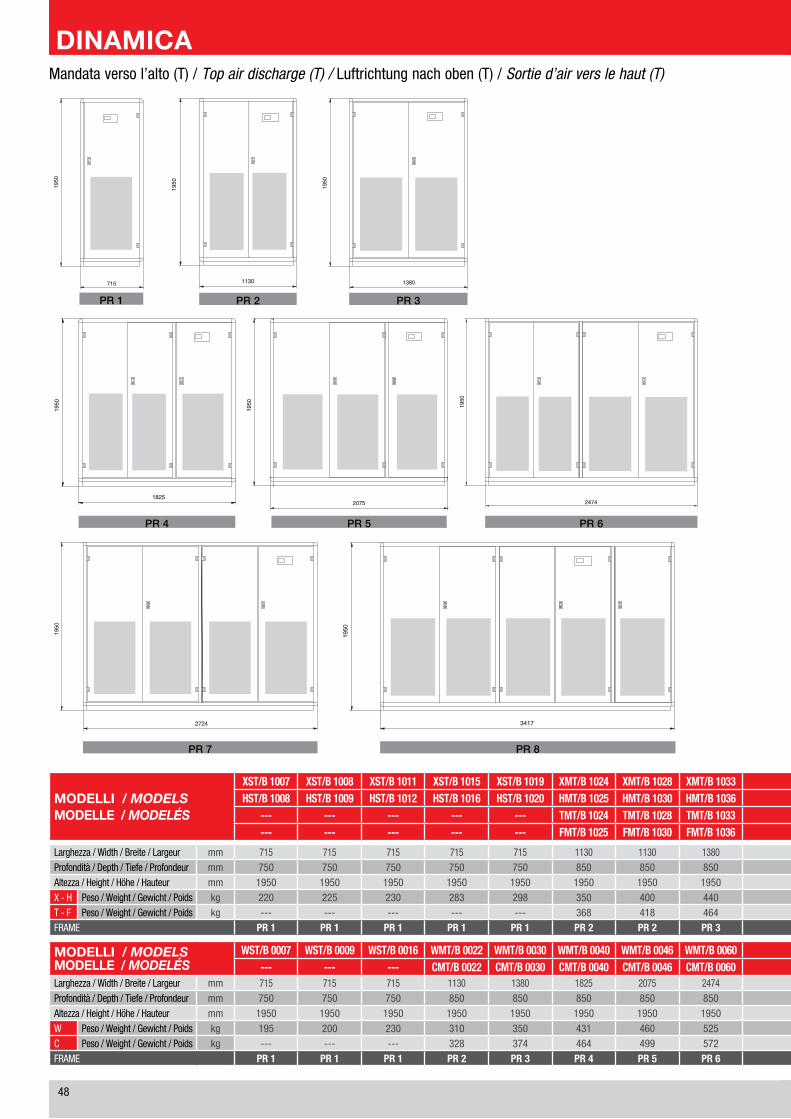
��
MODELLI / MODELSMODELLE / MODELÉS
XST/B 1007 XST/B 1008 XST/B 1011 XST/B 1015 XST/B 1019 XMT/B 1024 XMT/B 1028 XMT/B 1033 XMT/B 1038 XMT/B 1049 XMT/B 1062 XMT/B 2029 XMT/B 2038 XMT/B 2049 XMT/B 2058 XMT/B 2069 XMT/B 2078 XLT/B 2096 XLT/B 2125HST/B 1008 HST/B 1009 HST/B 1012 HST/B 1016 HST/B 1020 HMT/B 1025 HMT/B 1030 HMT/B 1036 HMT/B 1041 HMT/B 1053 HMT/B 1066 HMT/B 2031 HMT/B 2041 HMT/B 2055 HMT/B 2064 HMT/B 2074 HMT/B 2083 HLT/B 2104 HLT/B 2134
--- --- --- --- --- TMT/B 1024 TMT/B 1028 TMT/B 1033 TMT/B 1038 TMT/B 1049 TMT/B 1062 TMT/B 2029 TMT/B 2038 TMT/B 2049 TMT/B 2058 TMT/B 2069 TMT/B 2078 TMT/B 2096 TMT/B 2125--- --- --- --- --- FMT/B 1025 FMT/B 1030 FMT/B 1036 FMT/B 1041 FMT/B 1053 FMT/B 1066 FMT/B 2031 FMT/B 2041 FMT/B 2055 FMT/B 2064 FMT/B 2074 FMT/B 2083 FMT/B 2104 FMT/B 2134
Larghezza / Width / Breite / Largeur mm �1� �1� �1� �1� �1� 11�0 11�0 1��0 1��0 1��� �0�� 11�0 1��0 1��� �0�� ���� ���� ���� ��1�Profondità / Depth / Tiefe / Profondeur mm ��0 ��0 ��0 ��0 ��0 ��0 ��0 ��0 ��0 ��0 ��0 ��0 ��0 ��0 ��0 ��0 ��0 ��0 ��0Altezza / Height / Höhe / Hauteur mm 1��0 1��0 1��0 1��0 1��0 1��0 1��0 1��0 1��0 1��0 1��0 1��0 1��0 1��0 1��0 1��0 1��0 1��0 1��0X - H Peso / Weight / Gewicht / Poids kg ��0 ��� ��0 ��� ��� ��0 �00 ��0 ��� ��0 ��0 ��0 ��� ��0 ��� �10 �1� �0� ��0T - F Peso / Weight / Gewicht / Poids kg --- --- --- --- --- ��� �1� ��� ��� ��� �0� ��� ��� ��� ��� ��� ��� ��� 10��FRAME PR 1 PR 1 PR 1 PR 1 PR 1 PR 2 PR 2 PR 3 PR 3 PR 4 PR 5 PR 2 PR 3 PR 4 PR 5 PR 6 PR 6 PR 7 PR 8
MODELLI / MODELSMODELLE / MODELÉS
WST/B 0007 WST/B 0009 WST/B 0016 WMT/B 0022 WMT/B 0030 WMT/B 0040 WMT/B 0046 WMT/B 0060 WLT/B 0076 WLT/B 0102--- --- --- CMT/B 0022 CMT/B 0030 CMT/B 0040 CMT/B 0046 CMT/B 0060 CMT/B 0076 CMT/B 0102
Larghezza / Width / Breite / Largeur mm �1� �1� �1� 11�0 1��0 1��� �0�� ���� ���� ��1�Profondità / Depth / Tiefe / Profondeur mm ��0 ��0 ��0 ��0 ��0 ��0 ��0 ��0 ��0 ��0Altezza / Height / Höhe / Hauteur mm 1��0 1��0 1��0 1��0 1��0 1��0 1��0 1��0 1��0 1��0W Peso / Weight / Gewicht / Poids kg 1�� �00 ��0 �10 ��0 ��1 ��0 ��� ��� ��0C Peso / Weight / Gewicht / Poids kg --- --- --- ��� ��� ��� ��� ��� ��� �1�FRAME PR 1 PR 1 PR 1 PR 2 PR 3 PR 4 PR 5 PR 6 PR 7 PR 8
Mandata verso l’alto (T) / Top air discharge (T) / Luftrichtung nach oben (T) / Sortie d’air vers le haut (T)
PR 6PR 5PR 4
PR 3PR 2PR 1
PR 8PR 7
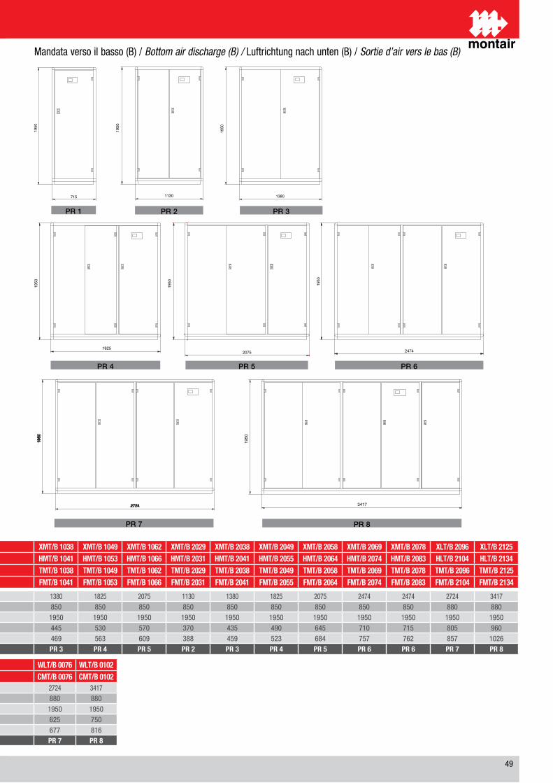
��
PR 8PR 7
PR 6PR 5PR 4
PR 3PR 2PR 1
Mandata verso il basso (B) / Bottom air discharge (B) / Luftrichtung nach unten (B) / Sortie d’air vers le bas (B)
MODELLI / MODELSMODELLE / MODELÉS
XST/B 1007 XST/B 1008 XST/B 1011 XST/B 1015 XST/B 1019 XMT/B 1024 XMT/B 1028 XMT/B 1033 XMT/B 1038 XMT/B 1049 XMT/B 1062 XMT/B 2029 XMT/B 2038 XMT/B 2049 XMT/B 2058 XMT/B 2069 XMT/B 2078 XLT/B 2096 XLT/B 2125HST/B 1008 HST/B 1009 HST/B 1012 HST/B 1016 HST/B 1020 HMT/B 1025 HMT/B 1030 HMT/B 1036 HMT/B 1041 HMT/B 1053 HMT/B 1066 HMT/B 2031 HMT/B 2041 HMT/B 2055 HMT/B 2064 HMT/B 2074 HMT/B 2083 HLT/B 2104 HLT/B 2134
--- --- --- --- --- TMT/B 1024 TMT/B 1028 TMT/B 1033 TMT/B 1038 TMT/B 1049 TMT/B 1062 TMT/B 2029 TMT/B 2038 TMT/B 2049 TMT/B 2058 TMT/B 2069 TMT/B 2078 TMT/B 2096 TMT/B 2125--- --- --- --- --- FMT/B 1025 FMT/B 1030 FMT/B 1036 FMT/B 1041 FMT/B 1053 FMT/B 1066 FMT/B 2031 FMT/B 2041 FMT/B 2055 FMT/B 2064 FMT/B 2074 FMT/B 2083 FMT/B 2104 FMT/B 2134
Larghezza / Width / Breite / Largeur mm �1� �1� �1� �1� �1� 11�0 11�0 1��0 1��0 1��� �0�� 11�0 1��0 1��� �0�� ���� ���� ���� ��1�Profondità / Depth / Tiefe / Profondeur mm ��0 ��0 ��0 ��0 ��0 ��0 ��0 ��0 ��0 ��0 ��0 ��0 ��0 ��0 ��0 ��0 ��0 ��0 ��0Altezza / Height / Höhe / Hauteur mm 1��0 1��0 1��0 1��0 1��0 1��0 1��0 1��0 1��0 1��0 1��0 1��0 1��0 1��0 1��0 1��0 1��0 1��0 1��0X - H Peso / Weight / Gewicht / Poids kg ��0 ��� ��0 ��� ��� ��0 �00 ��0 ��� ��0 ��0 ��0 ��� ��0 ��� �10 �1� �0� ��0T - F Peso / Weight / Gewicht / Poids kg --- --- --- --- --- ��� �1� ��� ��� ��� �0� ��� ��� ��� ��� ��� ��� ��� 10��FRAME PR 1 PR 1 PR 1 PR 1 PR 1 PR 2 PR 2 PR 3 PR 3 PR 4 PR 5 PR 2 PR 3 PR 4 PR 5 PR 6 PR 6 PR 7 PR 8
MODELLI / MODELSMODELLE / MODELÉS
WST/B 0007 WST/B 0009 WST/B 0016 WMT/B 0022 WMT/B 0030 WMT/B 0040 WMT/B 0046 WMT/B 0060 WLT/B 0076 WLT/B 0102--- --- --- CMT/B 0022 CMT/B 0030 CMT/B 0040 CMT/B 0046 CMT/B 0060 CMT/B 0076 CMT/B 0102
Larghezza / Width / Breite / Largeur mm �1� �1� �1� 11�0 1��0 1��� �0�� ���� ���� ��1�Profondità / Depth / Tiefe / Profondeur mm ��0 ��0 ��0 ��0 ��0 ��0 ��0 ��0 ��0 ��0Altezza / Height / Höhe / Hauteur mm 1��0 1��0 1��0 1��0 1��0 1��0 1��0 1��0 1��0 1��0W Peso / Weight / Gewicht / Poids kg 1�� �00 ��0 �10 ��0 ��1 ��0 ��� ��� ��0C Peso / Weight / Gewicht / Poids kg --- --- --- ��� ��� ��� ��� ��� ��� �1�FRAME PR 1 PR 1 PR 1 PR 2 PR 3 PR 4 PR 5 PR 6 PR 7 PR 8
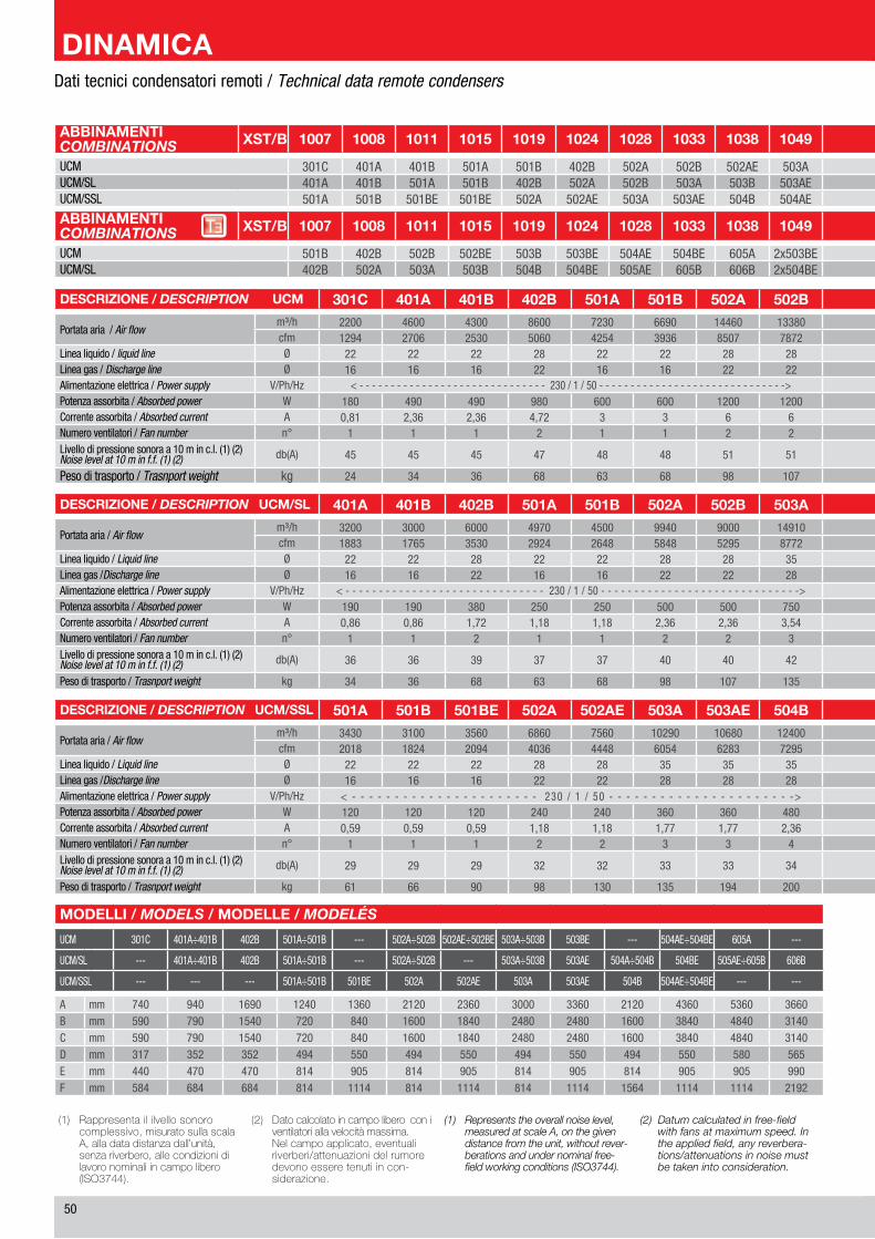
�0
ABBINAMENTICOMBINATIONS XST/B 1007 1008 1011 1015 1019 1024 1028 1033 1038 1049 1062 2029 2038 2049 2058 2069 2078 2096 2125 XST/B KOMBINATIONEN
COMBINAISONSUCM �01C �01A �01B �01A �01B �0�B �0�A �0�B �0�AE �0�A �0�B �x�01A �x�01B �x�0�B �x�0�A �x�0�B �x�0�AE �x�0�A �x�0�B UCMUCM/SL �01A �01B �01A �01B �0�B �0�A �0�B �0�A �0�B �0�AE �0�A �x�01B �x�0�B �x�0�A �x�0�B �x�0�A �x�0�B �x�0�AE �x�0�A UCM/SLUCM/SSL �01A �01B �01BE �01BE �0�A �0�AE �0�A �0�AE �0�B �0�AE �0�BE �x�01BE �x�0�A �x�0�AE �x�0�A �x�0�AE �x�0�B �x�0�AE �x�0�BE UCM/SSL
ABBINAMENTICOMBINATIONS XST/B 1007 1008 1011 1015 1019 1024 1028 1033 1038 1049 1062 2029 2038 2049 2058 2069 2078 2096 2125 XST/B KOMBINATIONEN
COMBINAISONSUCM �01B �0�B �0�B �0�BE �0�B �0�BE �0�AE �0�BE �0�A �x�0�BE �x�0�AE �x�0�BE �x�0�B �x�0�BE �x�0�AE �x�0�BE �x�0�A �x�0�BE �x�0�AE UCMUCM/SL �0�B �0�A �0�A �0�B �0�B �0�BE �0�AE �0�B �0�B �x�0�BE �x�0�AE �x�0�B �x�0�B �x�0�BE �x�0�AE �x�0�B �x�0�B �x�0�BE �x�0�AE UCM/SL
DESCRIZIONE / DESCRIPTION UCM 301C 401A 401B 402B 501A 501B 502A 502B 502AE 502BE 503A 503B 503BE 504AE 504BE 605A UCM BESCHREIBUNG / DESCRIPTION
Portata aria / Air flowm³/h ��00 ��00 ��00 ��00 ���0 ���0 1���0 1���0 1���0 1���0 �1��0 �00�0 ���00 �1�00 �0000 �0�00 m³/h
Luftmenge / Débits d’aircfm 1��� ��0� ���0 �0�0 ���� ���� ��0� ���� �1�� ���� 1���1 11�0� 1���� 1��0� 1���0 ����� cfm
Linea liquido / liquid line Ø �� �� �� �� �� �� �� �� �� �� �� �� �� �� �0 �� Ø Sauglinie / Ligne d’aspirationLinea gas / Discharge line Ø 1� 1� 1� �� 1� 1� �� �� �� �� �� �� �� �� �� �� Ø Flüssigkeitslinie / Ligne du liquideAlimentazione elettrica / Power supply V/Ph/Hz < - - - - - - - - - - - - - - - - - - - - - - - - - - - - - - ��0 / 1 / �0 - - - - - - - - - - - - - - - - - - - - - - - - - - - - - -> < - - - - - - - - - - - - - - - - - - - - - - - - - - - - - - ��0 / 1 / �0 - - - - - - - - - - - - - - - - - - - - - - - - - - - - - -> V/Ph/Hz Elektrische Einspeisung / AlimentationPotenza assorbita / Absorbed power W 1�0 ��0 ��0 ��0 �00 �00 1�00 1�00 1�00 1��0 1�00 1�00 �0�0 ���0 ���0 �000 W Leistungsaufnahme / Puissance absorbéeCorrente assorbita / Absorbed current A 0,�1 �,�� �,�� �,�� � � � � � � � � � 1� 1� 1�,1 A Stromaufnahme / Courant absorbéeNumero ventilatori / Fan number n° 1 1 1 � 1 1 � � � � � � � � � � n° Lufter Anzahl / Quantité ventilateursLivello di pressione sonora a 10 m in c.l. (1) (�)Noise level at 10 m in f.f. (1) (2) db(A) �� �� �� �� �� �� �1 �1 �1 �� �� �� �� �� �� �� db(A) Messung in 10 Meter Abstand von der Luftansaugseite (1) (�)
Niveau mèsuré en champs libre à 10 métres de l’unité (1) (2)
Peso di trasporto / Trasnport weight kg �� �� �� �� �� �� �� 10� 1�� 1�0 1�� 1�� �0� ��� ��1 ��� kg Transportgewicht / Poids d’expédition
DESCRIZIONE / DESCRIPTION UCM/SL 401A 401B 402B 501A 501B 502A 502B 503A 503B 503AE 504A 504B 504BE 505AE 605B 606B UCM/SL BESCHREIBUNG / DESCRIPTION
Portata aria / Air flowm³/h ��00 �000 �000 ���0 ��00 ���0 �000 1��10 1��00 1���0 1���0 1�000 �0��0 ���00 ��0�0 ����0 m³/h
Luftmenge / Débits d’aircfm 1��� 1��� ���0 ���� ���� ���� ���� ���� ���� ���0 11��� 10��0 1�0�� 1���0 1��1� 1���� cfm
Linea liquido / Liquid line Ø �� �� �� �� �� �� �� �� �� �� �� �� �� �� �� �0 Ø Sauglinie / Ligne d’aspirationLinea gas /Discharge line Ø 1� 1� �� 1� 1� �� �� �� �� �� �� �� �� �� �� �� Ø Flüssigkeitslinie / Ligne du liquideAlimentazione elettrica / Power supply V/Ph/Hz < - - - - - - - - - - - - - - - - - - - - - - - - - - - - - - ��0 / 1 / �0 - - - - - - - - - - - - - - - - - - - - - - - - - - - - - -> < - - - - - - - - - - - - - - - - - - - - - - - - - ��0 / 1 / �0 - - - - - - - - - - - - - - - - - - - - - - - - -> V/Ph/Hz Elektrische Einspeisung / AlimentationPotenza assorbita / Absorbed power W 1�0 1�0 ��0 ��0 ��0 �00 �00 ��0 ��0 ��0 1000 1000 10�0 1��0 1�00 �0�0 W Leistungsaufnahme / Puissance absorbéeCorrente assorbita / Absorbed current A 0,�� 0,�� 1,�� 1,1� 1,1� �,�� �,�� �,�� �,�� �,�� �,�� �,�� �,�� �,� �,� 10,�� A Stromaufnahme / Courant absorbéeNumero ventilatori / Fan number n° 1 1 � 1 1 � � � � � � � � � � � n° Lufter Anzahl / Quantité ventilateursLivello di pressione sonora a 10 m in c.l. (1) (�)Noise level at 10 m in f.f. (1) (2) db(A) �� �� �� �� �� �0 �0 �� �� �� �� �� �� �� �0 �1 db(A) Messung in 10 Meter Abstand von der Luftansaugseite (1) (�)
Niveau mèsuré en champs libre à 10 métres de l’unité (1) (2)Peso di trasporto / Trasnport weight kg �� �� �� �� �� �� 10� 1�� 1�� 1�1 1�� 1�� ��� ��� ��� ��� kg Transportgewicht / Poids d’expédition
Dati tecnici condensatori remoti / Technical data remote condensers
(1) Rappresentaililvellosonorocomplessivo,misuratosullascalaA,alladatadistanzadall’unità,senzariverbero,allecondizionidilavoronominaliincampolibero(ISO3744).
(2) Datocalcolatoincampoliberoconiventilatoriallavelocitàmassima.
Nelcampoapplicato,eventualiriverberi/attenuazionidelrumoredevonoesseretenutiincon-siderazione.
(1) Represents the overall noise level, measured at scale A, on the given distance from the unit, without rever-berations and under nominal free-field working conditions (ISO3744).
(2) Datum calculated in free-field with fans at maximum speed. In the applied field, any reverbera-tions/attenuations in noise must be taken into consideration.
DESCRIZIONE / DESCRIPTION UCM/SSL 501A 501B 501BE 502A 502AE 503A 503AE 504B 504AE 504BE UCM/SSL BESCHREIBUNG / DESCRIPTION
Portata aria / Air flowm³/h ���0 �100 ���0 ���0 ���0 10��0 10��0 1��00 1�1�0 1���0 m³/h
Luftmenge / Débits d’aircfm �01� 1��� �0�� �0�� ���� �0�� ���� ���� ���� ���� cfm
Linea liquido / Liquid line Ø �� �� �� �� �� �� �� �� �� �� Ø Sauglinie / Ligne d’aspirationLinea gas /Discharge line Ø 1� 1� 1� �� �� �� �� �� �� �� Ø Flüssigkeitslinie / Ligne du liquideAlimentazione elettrica / Power supply V/Ph/Hz < - - - - - - - - - - - - - - - - - - - - - - ��0 / 1 / �0 - - - - - - - - - - - - - - - - - - - - - -> ��0 / 1 / �0 V/Ph/Hz Elektrische Einspeisung / AlimentationPotenza assorbita / Absorbed power W 1�0 1�0 1�0 ��0 ��0 ��0 ��0 ��0 ��0 ��0 W Leistungsaufnahme / Puissance absorbéeCorrente assorbita / Absorbed current A 0,�� 0,�� 0,�� 1,1� 1,1� 1,�� 1,�� �,�� �,�� �,�� A Stromaufnahme / Courant absorbéeNumero ventilatori / Fan number n° 1 1 1 � � � � � � � n° Lufter Anzahl / Quantité ventilateursLivello di pressione sonora a 10 m in c.l. (1) (�)Noise level at 10 m in f.f. (1) (2) db(A) �� �� �� �� �� �� �� �� �� �� db(A) Messung in 10 Meter Abstand von der Luftansaugseite (1) (�)
Niveau mèsuré en champs libre à 10 métres de l’unité (1) (2)Peso di trasporto / Trasnport weight kg �1 �� �0 �� 1�0 1�� 1�� �00 ��� ��� kg Transportgewicht / Poids d’expédition
MODELLI / MODELS / MODELLE / MODELÉS
UCM �01C �01A÷�01B �0�B �01A÷�01B --- �0�A÷�0�B �0�AE÷�0�BE �0�A÷�0�B �0�BE --- �0�AE÷�0�BE �0�A ---
UCM/SL --- �01A÷�01B �0�B �01A÷�01B --- �0�A÷�0�B --- �0�A÷�0�B �0�AE �0�A÷�0�B �0�BE �0�AE÷�0�B �0�B
UCM/SSL --- --- --- �01A÷�01B �01BE �0�A �0�AE �0�A �0�AE �0�B �0�AE÷�0�BE --- ---
A mm ��0 ��0 1��0 1��0 1��0 �1�0 ���0 �000 ���0 �1�0 ���0 ���0 ���0B mm ��0 ��0 1��0 ��0 ��0 1�00 1��0 ���0 ���0 1�00 ���0 ���0 �1�0C mm ��0 ��0 1��0 ��0 ��0 1�00 1��0 ���0 ���0 1�00 ���0 ���0 �1�0D mm �1� ��� ��� ��� ��0 ��� ��0 ��� ��0 ��� ��0 ��0 ���E mm ��0 ��0 ��0 �1� �0� �1� �0� �1� �0� �1� �0� �0� ��0F mm ��� ��� ��� �1� 111� �1� 111� �1� 111� 1��� 111� 111� �1��
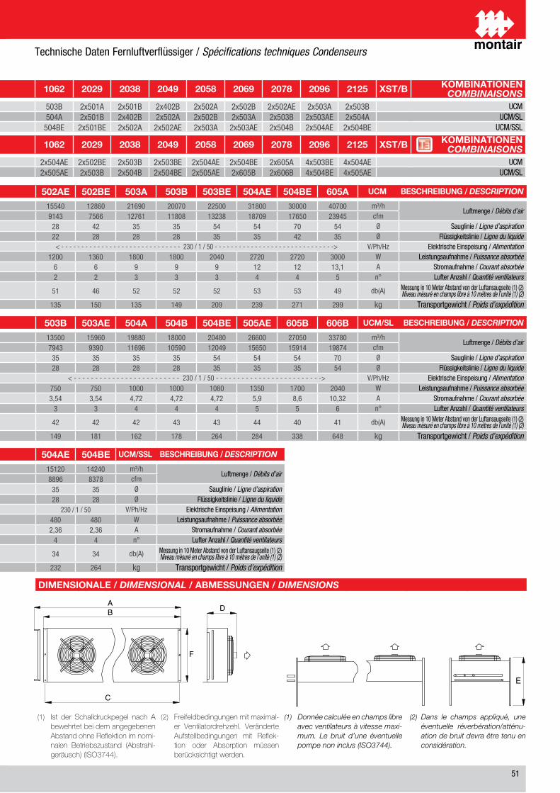
�1
ABBINAMENTICOMBINATIONS XST/B 1007 1008 1011 1015 1019 1024 1028 1033 1038 1049 1062 2029 2038 2049 2058 2069 2078 2096 2125 XST/B KOMBINATIONEN
COMBINAISONSUCM �01C �01A �01B �01A �01B �0�B �0�A �0�B �0�AE �0�A �0�B �x�01A �x�01B �x�0�B �x�0�A �x�0�B �x�0�AE �x�0�A �x�0�B UCMUCM/SL �01A �01B �01A �01B �0�B �0�A �0�B �0�A �0�B �0�AE �0�A �x�01B �x�0�B �x�0�A �x�0�B �x�0�A �x�0�B �x�0�AE �x�0�A UCM/SLUCM/SSL �01A �01B �01BE �01BE �0�A �0�AE �0�A �0�AE �0�B �0�AE �0�BE �x�01BE �x�0�A �x�0�AE �x�0�A �x�0�AE �x�0�B �x�0�AE �x�0�BE UCM/SSL
ABBINAMENTICOMBINATIONS XST/B 1007 1008 1011 1015 1019 1024 1028 1033 1038 1049 1062 2029 2038 2049 2058 2069 2078 2096 2125 XST/B KOMBINATIONEN
COMBINAISONSUCM �01B �0�B �0�B �0�BE �0�B �0�BE �0�AE �0�BE �0�A �x�0�BE �x�0�AE �x�0�BE �x�0�B �x�0�BE �x�0�AE �x�0�BE �x�0�A �x�0�BE �x�0�AE UCMUCM/SL �0�B �0�A �0�A �0�B �0�B �0�BE �0�AE �0�B �0�B �x�0�BE �x�0�AE �x�0�B �x�0�B �x�0�BE �x�0�AE �x�0�B �x�0�B �x�0�BE �x�0�AE UCM/SL
DIMENSIONALE / DIMENSIONAL / ABMESSUNGEN / DIMENSIONS
(1) Ist der Schalldruckpegel nach AbewehrtetbeidemangegebenenAbstandohneReflektionimnomi-nalen Betriebszustand (Abstrahl-geräusch)(ISO3744).
(2) Freifeldbedingungenmitmaximal-er Ventilatordrehzehl. VeränderteAufstellbedingungen mit Reflek-tion oder Absorption müssenberücksichtigtwerden.
(1) Donnée calculée en champs libre avec ventilateurs à vitesse maxi-mum. Le bruit d’une éventuelle pompe non inclus (ISO3744).
(2) Dans le champs appliqué, une éventuelle réverbération/atténu-ation de bruit devra être tenu en considération.
DESCRIZIONE / DESCRIPTION UCM 301C 401A 401B 402B 501A 501B 502A 502B 502AE 502BE 503A 503B 503BE 504AE 504BE 605A UCM BESCHREIBUNG / DESCRIPTION
Portata aria / Air flowm³/h ��00 ��00 ��00 ��00 ���0 ���0 1���0 1���0 1���0 1���0 �1��0 �00�0 ���00 �1�00 �0000 �0�00 m³/h
Luftmenge / Débits d’aircfm 1��� ��0� ���0 �0�0 ���� ���� ��0� ���� �1�� ���� 1���1 11�0� 1���� 1��0� 1���0 ����� cfm
Linea liquido / liquid line Ø �� �� �� �� �� �� �� �� �� �� �� �� �� �� �0 �� Ø Sauglinie / Ligne d’aspirationLinea gas / Discharge line Ø 1� 1� 1� �� 1� 1� �� �� �� �� �� �� �� �� �� �� Ø Flüssigkeitslinie / Ligne du liquideAlimentazione elettrica / Power supply V/Ph/Hz < - - - - - - - - - - - - - - - - - - - - - - - - - - - - - - ��0 / 1 / �0 - - - - - - - - - - - - - - - - - - - - - - - - - - - - - -> < - - - - - - - - - - - - - - - - - - - - - - - - - - - - - - ��0 / 1 / �0 - - - - - - - - - - - - - - - - - - - - - - - - - - - - - -> V/Ph/Hz Elektrische Einspeisung / AlimentationPotenza assorbita / Absorbed power W 1�0 ��0 ��0 ��0 �00 �00 1�00 1�00 1�00 1��0 1�00 1�00 �0�0 ���0 ���0 �000 W Leistungsaufnahme / Puissance absorbéeCorrente assorbita / Absorbed current A 0,�1 �,�� �,�� �,�� � � � � � � � � � 1� 1� 1�,1 A Stromaufnahme / Courant absorbéeNumero ventilatori / Fan number n° 1 1 1 � 1 1 � � � � � � � � � � n° Lufter Anzahl / Quantité ventilateursLivello di pressione sonora a 10 m in c.l. (1) (�)Noise level at 10 m in f.f. (1) (2) db(A) �� �� �� �� �� �� �1 �1 �1 �� �� �� �� �� �� �� db(A) Messung in 10 Meter Abstand von der Luftansaugseite (1) (�)
Niveau mèsuré en champs libre à 10 métres de l’unité (1) (2)
Peso di trasporto / Trasnport weight kg �� �� �� �� �� �� �� 10� 1�� 1�0 1�� 1�� �0� ��� ��1 ��� kg Transportgewicht / Poids d’expédition
DESCRIZIONE / DESCRIPTION UCM/SL 401A 401B 402B 501A 501B 502A 502B 503A 503B 503AE 504A 504B 504BE 505AE 605B 606B UCM/SL BESCHREIBUNG / DESCRIPTION
Portata aria / Air flowm³/h ��00 �000 �000 ���0 ��00 ���0 �000 1��10 1��00 1���0 1���0 1�000 �0��0 ���00 ��0�0 ����0 m³/h
Luftmenge / Débits d’aircfm 1��� 1��� ���0 ���� ���� ���� ���� ���� ���� ���0 11��� 10��0 1�0�� 1���0 1��1� 1���� cfm
Linea liquido / Liquid line Ø �� �� �� �� �� �� �� �� �� �� �� �� �� �� �� �0 Ø Sauglinie / Ligne d’aspirationLinea gas /Discharge line Ø 1� 1� �� 1� 1� �� �� �� �� �� �� �� �� �� �� �� Ø Flüssigkeitslinie / Ligne du liquideAlimentazione elettrica / Power supply V/Ph/Hz < - - - - - - - - - - - - - - - - - - - - - - - - - - - - - - ��0 / 1 / �0 - - - - - - - - - - - - - - - - - - - - - - - - - - - - - -> < - - - - - - - - - - - - - - - - - - - - - - - - - ��0 / 1 / �0 - - - - - - - - - - - - - - - - - - - - - - - - -> V/Ph/Hz Elektrische Einspeisung / AlimentationPotenza assorbita / Absorbed power W 1�0 1�0 ��0 ��0 ��0 �00 �00 ��0 ��0 ��0 1000 1000 10�0 1��0 1�00 �0�0 W Leistungsaufnahme / Puissance absorbéeCorrente assorbita / Absorbed current A 0,�� 0,�� 1,�� 1,1� 1,1� �,�� �,�� �,�� �,�� �,�� �,�� �,�� �,�� �,� �,� 10,�� A Stromaufnahme / Courant absorbéeNumero ventilatori / Fan number n° 1 1 � 1 1 � � � � � � � � � � � n° Lufter Anzahl / Quantité ventilateursLivello di pressione sonora a 10 m in c.l. (1) (�)Noise level at 10 m in f.f. (1) (2) db(A) �� �� �� �� �� �0 �0 �� �� �� �� �� �� �� �0 �1 db(A) Messung in 10 Meter Abstand von der Luftansaugseite (1) (�)
Niveau mèsuré en champs libre à 10 métres de l’unité (1) (2)Peso di trasporto / Trasnport weight kg �� �� �� �� �� �� 10� 1�� 1�� 1�1 1�� 1�� ��� ��� ��� ��� kg Transportgewicht / Poids d’expédition
Dati tecnici condensatori remoti / Technical data remote condensers
DESCRIZIONE / DESCRIPTION UCM/SSL 501A 501B 501BE 502A 502AE 503A 503AE 504B 504AE 504BE UCM/SSL BESCHREIBUNG / DESCRIPTION
Portata aria / Air flowm³/h ���0 �100 ���0 ���0 ���0 10��0 10��0 1��00 1�1�0 1���0 m³/h
Luftmenge / Débits d’aircfm �01� 1��� �0�� �0�� ���� �0�� ���� ���� ���� ���� cfm
Linea liquido / Liquid line Ø �� �� �� �� �� �� �� �� �� �� Ø Sauglinie / Ligne d’aspirationLinea gas /Discharge line Ø 1� 1� 1� �� �� �� �� �� �� �� Ø Flüssigkeitslinie / Ligne du liquideAlimentazione elettrica / Power supply V/Ph/Hz < - - - - - - - - - - - - - - - - - - - - - - ��0 / 1 / �0 - - - - - - - - - - - - - - - - - - - - - -> ��0 / 1 / �0 V/Ph/Hz Elektrische Einspeisung / AlimentationPotenza assorbita / Absorbed power W 1�0 1�0 1�0 ��0 ��0 ��0 ��0 ��0 ��0 ��0 W Leistungsaufnahme / Puissance absorbéeCorrente assorbita / Absorbed current A 0,�� 0,�� 0,�� 1,1� 1,1� 1,�� 1,�� �,�� �,�� �,�� A Stromaufnahme / Courant absorbéeNumero ventilatori / Fan number n° 1 1 1 � � � � � � � n° Lufter Anzahl / Quantité ventilateursLivello di pressione sonora a 10 m in c.l. (1) (�)Noise level at 10 m in f.f. (1) (2) db(A) �� �� �� �� �� �� �� �� �� �� db(A) Messung in 10 Meter Abstand von der Luftansaugseite (1) (�)
Niveau mèsuré en champs libre à 10 métres de l’unité (1) (2)Peso di trasporto / Trasnport weight kg �1 �� �0 �� 1�0 1�� 1�� �00 ��� ��� kg Transportgewicht / Poids d’expédition
MODELLI / MODELS / MODELLE / MODELÉS
UCM �01C �01A÷�01B �0�B �01A÷�01B --- �0�A÷�0�B �0�AE÷�0�BE �0�A÷�0�B �0�BE --- �0�AE÷�0�BE �0�A ---
UCM/SL --- �01A÷�01B �0�B �01A÷�01B --- �0�A÷�0�B --- �0�A÷�0�B �0�AE �0�A÷�0�B �0�BE �0�AE÷�0�B �0�B
UCM/SSL --- --- --- �01A÷�01B �01BE �0�A �0�AE �0�A �0�AE �0�B �0�AE÷�0�BE --- ---
A mm ��0 ��0 1��0 1��0 1��0 �1�0 ���0 �000 ���0 �1�0 ���0 ���0 ���0B mm ��0 ��0 1��0 ��0 ��0 1�00 1��0 ���0 ���0 1�00 ���0 ���0 �1�0C mm ��0 ��0 1��0 ��0 ��0 1�00 1��0 ���0 ���0 1�00 ���0 ���0 �1�0D mm �1� ��� ��� ��� ��0 ��� ��0 ��� ��0 ��� ��0 ��0 ���E mm ��0 ��0 ��0 �1� �0� �1� �0� �1� �0� �1� �0� �0� ��0F mm ��� ��� ��� �1� 111� �1� 111� �1� 111� 1��� 111� 111� �1��
Technische Daten Fernluftverflüssiger / Spécifications techniques Condenseurs
200M
TB00
28AB
CD -1
00 -
Emiss
ione
/ Iss
ue /
Ausg
abe
/ Edit
ion 0
2 / 2
011
Via Max Piccini, 11/13 • 33050 RIVIGNANO (UD) • ITALYTel. +39 0432 823011 • Fax +39 0432 773855www.montair.it • e-mail: [email protected]