Biocompatible and Biodegradable Nanogels and Hydrogels for ...
Design of Smart Polymeric Materials with
Responsive / Adaptive Adhesion Properties
DISSERTATION
zur Erlangung des akademischen Grades
Doktor rerum naturalium (Dr. rer. nat.)
vorgelegt
der Fakultät Mathematik und Naturwissenschaften der Technischen Universität Dresden
von
M.Sc. Ekaterina Biehlig, geb. Svetushkina
geboren am 04.08.1984 in Moskau
Eingereicht am
Die Dissertation wurde in der Zeit von November 2008 bis November 2012 im Leibniz‐
Institut für Polymerforschung Dresden e.V. angefertigt.

Table of Contents
Table of Contents
List of Abbreviations ........................................................................................ 8
I. INTRODUCTION ......................................................................... 11
1. Preface ................................................................................................... 11
2. Motivation and Goals ............................................................................. 11
3. Outline ................................................................................................... 14
II. THEORETICAL BACKGROUND .................................................... 15
1. Adhesion and tackiness. Fundamentals ..................................................... 15 1.1 General .......................................................................................................... 15
1.2 Molecular interactions at interface ............................................................... 16
1.3 Mechanical properties (elasticity) of adhesives ............................................. 19
1.4 Contact area (surface roughness) .................................................................. 20
2. Switchable and adaptable adhesion .......................................................... 21 2.1 Switching of adhesion by chemical functionality ........................................... 22
2.2 Switching of adhesion by surface topography ............................................... 29
3. Stimuli‐responsive materials and polymer brushes ................................... 32 3.1 Polymer brushes ............................................................................................ 33
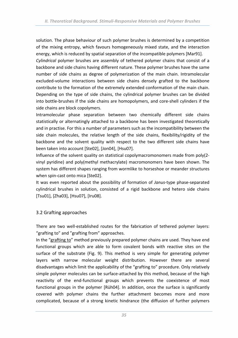
3.2 Grafting approaches ...................................................................................... 35
4. Application of adhesives with responsive and adaptive properties .......... 39 4.1 Biomedical applications ................................................................................. 39
4.2 Engineering (non‐biomedical) applications ................................................... 40
5. Surface characterisation techniques .......................................................... 41
Table of Contents
5.1 Atomic force microscopy .............................................................................. 41
5.1.1 Topographical measurements ............................................................................ 42
5.1.2 Force measurements .......................................................................................... 45
5.1.3 Colloidal probe technique ................................................................................... 48
5.2 Ellipsometry .................................................................................................. 49
5.3 Gel permeation chromatography (GPC) ........................................................ 51
5.4 X‐ray photoelectron spectroscopy (XPS) ....................................................... 52
5.5 Wetting measurements ................................................................................ 52
5.6 Electrokinetic measurements ....................................................................... 55
5.7 Dynamic light scattering (DLS) ...................................................................... 55
5.8 Scanning electron microscope (SEM) ............................................................ 55
5.9 Transmission electron microscope (Cryo‐TEM) ............................................. 56
5.10 Tack test ...................................................................................................... 56
III. RESULTS AND DISCUSSIONS ....................................................... 61
1. Thermoresponsive polymer brushes.......................................................... 61 1.1 Abstract ......................................................................................................... 61
1.2 Introduction .................................................................................................. 61
1.3 Experimental Part ......................................................................................... 62
1.3.1 Materials ............................................................................................................. 62
1.3.2 Modification of planar substrates ...................................................................... 63
1.3.3 Modification of curved substrates (colloidal particles) ...................................... 65
1.3.4 Preparation of rough substrates from core‐shell particles ................................ 65
1.3.5 Polymerization on flat and rough surfaces ......................................................... 67
1.4 Surface properties evaluation ....................................................................... 70
1.4.1 Swelling behaviour .............................................................................................. 70
1.4.2 Wetting properties .............................................................................................. 73
1.4.3 Electrokinetic properties ..................................................................................... 74
1.4.4 Surface morphology ............................................................................................ 75
Table of Contents
1.5 Adhesion properties of thermoresponsive polymer brushes ........................ 76
1.5.1 Effect of scanning parameters of force measurements ..................................... 77
1.5.2 Effect of chain architecture ................................................................................ 82
1.5.3 Effect of tip geometry/radius ............................................................................. 85
1.5.4 Effect of surface roughness and chemical functionality of colloidal probe ....... 87
1.6 Summary ....................................................................................................... 91
2. Solvent responsive and adaptive polymer brushes ................................... 93 2.1 Abstract ......................................................................................................... 93
2.2 Introduction ................................................................................................... 93
2.3 Experimental Part .......................................................................................... 94
2.3.1 Materials ............................................................................................................. 94
2.3.2 Modification of planar substrates ...................................................................... 94
2.3.3 Growing of polymer brushes from flat and rough surfaces ............................... 94
2.4 Surface properties evaluation ....................................................................... 99
2.4.1 Wetting properties .............................................................................................. 99
2.4.2 Swelling properties ........................................................................................... 103
2.4.3 Electrokinetic measurements ........................................................................... 105
2.4.4 Surface morphology .......................................................................................... 106
2.5 Adhesion properties of solvent responsive and adaptive brushes .............. 112
2.5.1 Effect of Maximal Load ..................................................................................... 112
2.5.2 Effect of Scan Rate ............................................................................................ 113
2.5.3 Effect of Ramp Delay ......................................................................................... 114
2.5.4 Effect of temperature ....................................................................................... 115
2.5.5 Effect of chemical composition ........................................................................ 116
2.5.6 Effect of length of polymer chain ..................................................................... 119
2.5.7 Effect of chain architecture .............................................................................. 121
2.5.8 Effect of surface roughness .............................................................................. 124
2.5.9 Effect of surface functionality of colloidal probe ............................................. 126
2.6 Summary ..................................................................................................... 128
Table of Contents
3. Comparative study of adhesion behaviour depending on elasticity of adhesion probe ............................................................................................ 131 3.1 Abstract ........................................................................................................131
3.2 Introduction .................................................................................................131
3.3 Sample preparation......................................................................................131
3.4 Tack test with elastic probe .........................................................................132
3.5 Comparison of adhesion behaviour measured using hard and soft probes .136
3.6 Summary ......................................................................................................139
IV. SUMMARY............................................................................... 141
V. OUTLOOK ................................................................................ 143
VI. REFERENCES ............................................................................ 145
VII. APPENDIX ................................................................................ 161 Curriculum vitae .................................................................................................161
List of Publications .............................................................................................163
Acknowledgements ............................................................................................165
Versicherung ......................................................................................................167

List of Abbreviations
8
List of Abbreviations
ΘAdv Advancing contact angle
ΘRec Receding contact angle
ADSA Axisymmetric drop shape analysis
AFM Atomic force microscopy
AGET ATRP Activator generated by electron transfer atom transfer radical
polymerization
APS 3‐aminopropyltriethoxysilane
ARXPS Angle resolved X‐ray photoelectron spectroscopy
ATP Adenosine triphosphate
ATRP Atom transfer radical polymerization
BrInit Bromide initiator
CA Contact angle
CP Colloidal probe
CSC Core‐shell‐corona
DCA Dynamic contact angle
DI Deionized
DLS Dynamic light scattering
DLVO Derjaguin, Landau, Verwey, Overbeek
DMF N,N ‐ Dimethylformamide
DMT Derjaguin‐Muller‐Toporov
DSA Drop shape analysis
EbiB Ethyl‐2‐bromoisobutyrate
IEP Isoelectric point
GPC Gel permeation chromatography
LCST Lower critical solution temperature
LSA Light switchable adhesives
MEO2MA 2‐(2‐methoxyethoxy) ethyl methacrylate)
Mn Number average molecular weight
Mw Weight average molecular weight
OEGMA Oligo(ethylene glycol) methyl ether methacrylate
OPGMA Oligo(propylene glycol) methacrylate
NIPAM N‐isopropylacrylamide
nBA n‐butyl acrylate
PAA Poly(acrylic acid)
PDI Polydispersity index
PDMS Poly(dimethylsiloxane)
PEG Poly(ethylene glycol)
List of Abbreviations
9
PEO Poly(ethylene oxide)
PFDTS 1H,1H,2H,2H‐Perfluorodecyltrichlorosilane
PGMA Poly(glycidyl methacrylate)
PMDTA N,N,N',N'',N''‐pentamethyldiethylenetriamine
PNIPAM Poly(N‐isopropylacrylamide)
PS Polystyrene
P2VP Poly(2‐vinylpyridine)
rms Root‐mean‐square
RNA Ribonucleic acid
RNAse Ribonuclease
SIS Styrene‐isoprene‐styrene
SMP Shape memory polymer
SPM Scanning probe microscopy
STM Scanning tunnelling microscope
TEM Transmission electron microscopy
TGA Thermo‐gravimetrical analysis
vdW van der Waals
XPS X‐ray photoelectron spectroscopy

I. Introduction
11
I. Introduction
1. Preface
This work was carried out during the years 2008‐2012 at Leibniz‐Institut für
Polymerforschung Dresden e.V. under the supervision of Professor Manfred Stamm and
Doctor Alla Synytska.
Collaboration with the group of Professor Costantino Creton made possible one part of
this work carried out at ESPCI (École Supérieure de Physique et de Chimie Industrielles
de la ville de Paris, laboratoire de Physico‐Chimie des Polymeres et Milieux Disperses).
The research was supported by funding from the Leibniz‐Institut für Polymerforschung
Dresden e.V. and Deutsche Forschungsgemeinschaft DFG (Grant SY 125/1‐1).
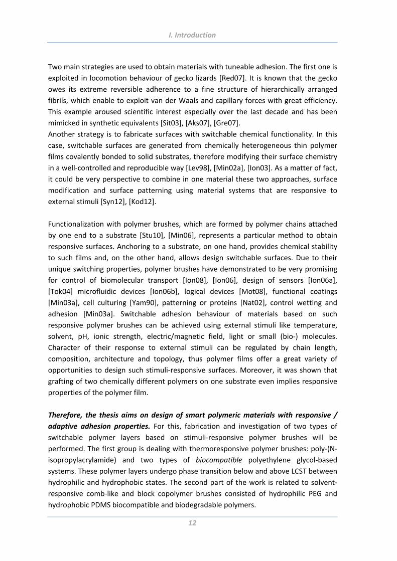
2. Motivation and Goals
Adhesion between different objects is happening everywhere. Without it, simple
procedures like walking or holding something in a hand or attaching a postage stamp
would be impossible. The life itself depends on adhesion on all levels, starting from the
interactions between the living cells.
The control of adhesion is very important in many fields ranging from industrial
purposes to biomedical applications and everyday usage. There is a demand for “smart”
materials with integrated functionalities that make them responsive, switchable,
biocompatible, anti‐bacterial, more energy efficient, or autonomous. In particular,
materials for such cutting‐edge applications like cell culture, drug delivery, tissue
engineering, biosensors, anti/biofouling, microfluidics, climbing robots, sport equipment
and many others should possess adjustable/tuneable adhesive properties.
Much effort has been directed toward the fabrication of materials with either weak or
strong adhesion depending on the field of application. However, design of “smart”
surfaces with reversibly controllable adhesion is still a very challenging task. There are
numerous instances in nature where responsive surfaces have been observed [Yos08],
[Xia08]. Borrowing this concept from nature and applying it for reversible switchability
and adaptation of surface properties has created considerable excitement in the fields of
material science and biotechnology [Nan10].
I. Introduction
12
Two main strategies are used to obtain materials with tuneable adhesion. The first one is
exploited in locomotion behaviour of gecko lizards [Red07]. It is known that the gecko
owes its extreme reversible adherence to a fine structure of hierarchically arranged
fibrils, which enable to exploit van der Waals and capillary forces with great efficiency.
This example aroused scientific interest especially over the last decade and has been
mimicked in synthetic equivalents [Sit03], [Aks07], [Gre07].
Another strategy is to fabricate surfaces with switchable chemical functionality. In this
case, switchable surfaces are generated from chemically heterogeneous thin polymer
films covalently bonded to solid substrates, therefore modifying their surface chemistry
in a well‐controlled and reproducible way [Lev98], [Min02a], [Ion03]. As a matter of fact,
it could be very perspective to combine in one material these two approaches, surface
modification and surface patterning using material systems that are responsive to
external stimuli [Syn12], [Kod12].
Functionalization with polymer brushes, which are formed by polymer chains attached
by one end to a substrate [Stu10], [Min06], represents a particular method to obtain
responsive surfaces. Anchoring to a substrate, on one hand, provides chemical stability
to such films and, on the other hand, allows design switchable surfaces. Due to their
unique switching properties, polymer brushes have demonstrated to be very promising
for control of biomolecular transport [Ion08], [Ion06], design of sensors [Ion06a],
[Tok04] microfluidic devices [Ion06b], logical devices [Mot08], functional coatings
[Min03a], cell culturing [Yam90], patterning or proteins [Nat02], control wetting and
adhesion [Min03a]. Switchable adhesion behaviour of materials based on such
responsive polymer brushes can be achieved using external stimuli like temperature,
solvent, pH, ionic strength, electric/magnetic field, light or small (bio‐) molecules.
Character of their response to external stimuli can be regulated by chain length,
composition, architecture and topology, thus polymer films offer a great variety of
opportunities to design such stimuli‐responsive surfaces. Moreover, it was shown that
grafting of two chemically different polymers on one substrate even implies responsive
properties of the polymer film.
Therefore, the thesis aims on design of smart polymeric materials with responsive /
adaptive adhesion properties. For this, fabrication and investigation of two types of
switchable polymer layers based on stimuli‐responsive polymer brushes will be
performed. The first group is dealing with thermoresponsive polymer brushes: poly‐(N‐
isopropylacrylamide) and two types of biocompatible polyethylene glycol‐based
systems. These polymer layers undergo phase transition below and above LCST between
hydrophilic and hydrophobic states. The second part of the work is related to solvent‐
responsive comb‐like and block copolymer brushes consisted of hydrophilic PEG and
hydrophobic PDMS biocompatible and biodegradable polymers.
I. Introduction
13
Following steps will be performed in this work:
Synthesis of the polymer brushes on flat and rough substrates using ATRP
process;
Characterization and control over their bulk and surface properties (grafting
density, thickness, wetting and swelling properties, surface charges and surface
topography);
Investigation and control of switchable adhesion behaviour of designed materials
under the influence of external stimuli by means of AFM force measurements.
Monitoring of several important chemical and physical surface characteristics will
be performed:
‐ chemical functionality of brush layer;
‐ polymer layers architecture;
‐ polymer layers thickness;
‐ surface topography/roughness.
Influence of AFM measuring process parameters will be investigated as well:
‐ parameters of scanning (applied force, scan rate, contact time);
‐ geometry/radius of the probing tip;
‐ surface functionality of the colloidal probe.
Investigation of effect of mechanical properties of probing surfaces used in AFM
and Tack test experiments;
Analysis of all aspects and parameters influencing adhesion behaviour of stimuli‐
responsive polymer brushes.
I. Introduction
14
3. Outline
The thesis is organized in six parts. The Introduction in the Chapter I gives the general
information concerning the topic of this work. The field and directions of research,
motivation and goals of the present work are defined here.
The theoretical background of adhesion phenomena and the possibilities of materials
with tuneable adhesion properties are discussed first in Chapter II. Then, the progress of
current research concerning stimuli‐responsive polymers, materials made on their basis
and the possible areas of their application are presented. Methods for preparation of
polymer brushes as well as surface characterisation techniques are also the subjects of
this chapter.
Chapter III presents the results of investigation of polymeric systems with switchable
adhesion properties. This chapter is divided into three parts. The first one is dealing with
temperature responsive polymer brushes, whereas the second part is about solution
responsive brushes. In the third part, the results on comparative study of adhesion
properties of solution responsive systems measured with soft and hard probes are
presented.
The general conclusions are presented in Chapter IV Summary. The perspectives of the
further work in the field of stimuli‐responsive materials are presented in Chapter V
Outlook. In the last part of the work, the literature sources, Curriculum vitae and List of
publications are listed.
II. Theoretical Background. Adhesion and Tackiness. Fundamentals
15
II. Theoretical Background
1. Adhesion and tackiness. Fundamentals
1.1 General
The term adhesion is used when referring to the attraction between the substances.
Two bodies are said to adhere when energy is needed to achieve separation [Gay02]. As
a means of joining materials adhesives have been used by mankind for many centuries
[Kin87]. The oldest known adhesive, dated to approximately 200,000 BC, is from spear
stone flakes glued to a wood with birch‐bark‐tar, which was found in central Italy.
There are many samples of adhesives in nature. A lot of invertebrates secrete
bioadhesives for different purposes: to secure themselves, their nests, or their eggs, to
build and construct (attachment of pupae, spider’s webs), as well as for obstruction and
predation (elastic "frog glue" of crucifix toad [Gra05], sticky saliva of velvet worms).
While bioadhesives from some marine molluscs are already being researched intensively
[Mes02], [Bil10], [Sag06], many insects remain relatively unexplored field of potentially
useful and promising adhesives. Study of bioadhesion may well uncover qualitatively
new adhesion mechanisms [Gay02].
The science and technology of adhesion and adhesives have achieved a significant
progress in the last decades [Kin87]. There is a plenty of various examples of adhesive or
non‐adhesive materials. These materials find wide applications in many industrial
processes, health care applications (such as surgical adhesives and sealants), everyday
usage, etc [Rus99], [Rus02]. The adhesives may be natural (starches or natural rubber
cements, for example), organic (such as derivatives of collagen, proteins, or cellulose), or
synthetic (usually polymer‐based thermosets, thermoplastics, or elastomers) [Rus99],
[Rus02]. Synthetic adhesives are usually soft sticky materials that do not flow, made of
polymers of various molecular architecture (crosslinked polymers, block‐copolymers)
[Gay02], [Gay03], [Cre02].
Adhesion between two substrates is a complex phenomenon, which at present is still
not well understood [Fou95]. There are several factors determining the strength of
adhesion [Gay02], [Bur05], [Bhu06]: (i) molecular interactions at interface [Isr92], (ii)
mechanical properties of adhesive [Car96], [Sha96] and (iii) area of contact between
adhesive and probing surface [Gay02], [Bur05], [Bhu06], [Cre96], [Gre07]. Two surfaces
are tacky when they possess the right balance between mechanical properties,
molecular interactions at their interface and have large enough area of contact.
II. Theoretical Background. Adhesion and Tackiness. Fundamentals
16
1.2 Molecular interactions at interface
When two individual atoms, macromolecules or surfaces are approaching each other,
they can form chemical bonds or interact physically. There are several types of physical
intermolecular interactions that could act and that should be taken into account while
speaking about adhesion phenomena: van der Waals forces, electrostatic and
hydrophobic interactions, hydrogen bonds, as well as steric effects.
Van der Waals (vdW) forces, have electrostatic nature and act between any molecules
and macroscopic bodies [Isr92]. The vdW forces differ from chemical interactions that
lead to molecular bonding and demonstrate saturation: two molecules attracted via
vdW forces are able to attract other molecules [Dut00]. These interactions arise from
the fluctuations in the electric dipole moments of molecules which become correlated
as the molecules come closer together, giving rise to an attractive force. This force can
be also repulsive, but is always attractive between similar molecules or materials [Isr01].
The vdW forces are long‐range and depend on nature of interacting bodies and their
surrounding medium. Significant values of vdW forces are present on smooth surfaces
and in fluids, but decrease with growing of roughness [Jon02]. The forces are inversely
proportional to distance between the surfaces [Hem11]. The energy of the vdW
interactions received from quantum mechanical calculations is equal to:
UvdW(d)= ‐B/d6 (eq. 1)
where d – is the distance between molecules, B – characteristic constant; the negative
value shows the attractive character of vdW forces.
The vdW forces depend on polarizability of molecules and include dipole‐dipole, dipole‐
induced dipole, and instantaneous induced dipole ‐ induced dipole forces.
Dipole‐dipole or Keesom force arises between permanent dipoles because of
asymmetric distribution of charges inside the molecules. They tend to align the
molecules to increase the attraction reducing the potential energy.
Dipole‐induced dipole interactions (Debye force) appear between a molecule that
possesses a permanent dipole and other uncharged molecule. The dipole moment on
the first molecule generates an electric field and induces a dipole moment on other
molecule. These forces are weaker then dipole‐dipole, but stronger then London
dispersion forces.
Instantaneous induced dipole ‐ induced dipole or London dispersion forces result from
temporary charge imbalances and act between nonpolar molecules. The forces arise
from electric field fluctuation results in shifting of electric clouds about the nucleus. In
II. Theoretical Background. Adhesion and Tackiness. Fundamentals
17
such a way even on nonpolar molecules the formation of the fluctuated dipole moments
is possible; they can even provoke shift of charges on neighbouring molecules.
Hydrogen bond is a type of attractive (dipole‐dipole) interaction of a hydrogen atom
with an electronegative atom, such as nitrogen, oxygen or fluorine, which comes from
another molecule or chemical group. Polar molecules, such as water molecules, have a
weak, partial negative charge at one region of the molecule (the oxygen atom in water)
and a partial positive charge elsewhere (the hydrogen atoms in water). Thus when water
molecules are close together, their positive and negative regions are attracted to the
oppositely‐charged regions of nearby molecules.
A hydrogen bond tends to be stronger than van der Waals forces, but weaker than
covalent bonds or ionic bonds. However, if many hydrogen bonds are formed between
two molecules (or parts of the same molecule), the resulting union can be sufficiently
strong and be quite stable. This type of bond occurs in both inorganic molecules such as
water and organic molecules like DNA.
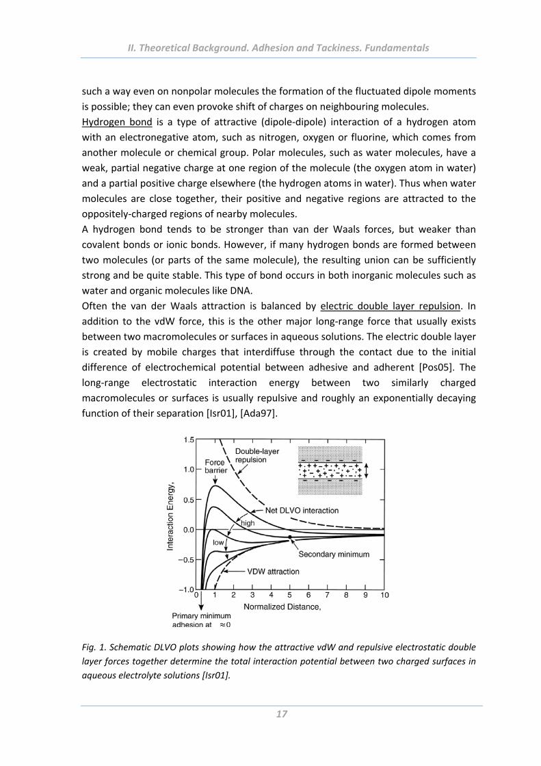
Often the van der Waals attraction is balanced by electric double layer repulsion. In
addition to the vdW force, this is the other major long‐range force that usually exists
between two macromolecules or surfaces in aqueous solutions. The electric double layer
is created by mobile charges that interdiffuse through the contact due to the initial
difference of electrochemical potential between adhesive and adherent [Pos05]. The
long‐range electrostatic interaction energy between two similarly charged
macromolecules or surfaces is usually repulsive and roughly an exponentially decaying
function of their separation [Isr01], [Ada97].
Fig. 1. Schematic DLVO plots showing how the attractive vdW and repulsive electrostatic double
layer forces together determine the total interaction potential between two charged surfaces in
aqueous electrolyte solutions [Isr01].
II. Theoretical Background. Adhesion and Tackiness. Fundamentals
18
The van der Waals and electric double layer forces make up the two forces of the so‐
called DLVO theory of colloid stability, after Derjaguin&Landau (1941), and
Verwey&Overbeek (1948) [Isr01] (Fig. 1). The DLVO theory has been found to
adequately describe the long‐range forces between similarly charged colloidal and some
bio‐colloidal surfaces in aqueous solutions [Isr01].
Hydrophobic interactions are long range attractive forces exhibited by hydrophobic
molecules or surfaces in water and aqueous solutions [Fag02]. The first direct force
measurement between two hydrophobic surfaces was reported by Israelachvili and
Pashley in 1982 which showed that the magnitude of the force is greater than vdW force
[Isr82]. Notably, it is not the interactions between the hydrophobic molecules that make
them together, but generation of favourable entropy while decreasing of a surface area
between the solvent and the hydrophobic solute component. This entropic gain is
responsible for almost all associations in the medium water and hence of extreme
importance for life (formation of membranes, micelles, protein folding etc.).
Steric interactions. Macromolecular interpenetrating [Rap92] or elongation [Lak67] may
also influence the strength of the interface for specific substrate‐adhesive pairs [Gay02].
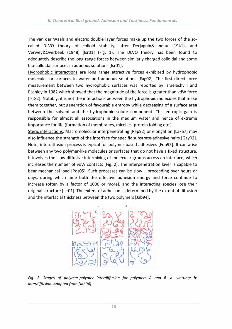
Note, interdiffusion process is typical for polymer‐based adhesives [Fou95]. It can arise
between any two polymer‐like molecules or surfaces that do not have a fixed structure.
It involves the slow diffusive intermixing of molecular groups across an interface, which
increases the number of vdW contacts (Fig. 2). The interpenetration layer is capable to
bear mechanical load [Pos05]. Such processes can be slow – proceeding over hours or
days, during which time both the effective adhesion energy and force continue to
increase (often by a factor of 1000 or more), and the interacting species lose their
original structure [Isr01]. The extent of adhesion is determined by the extent of diffusion
and the interfacial thickness between the two polymers [Jab94].
Fig. 2. Stages of polymer‐polymer interdiffusion for polymers A and B. a: wetting; b:
interdiffusion. Adapted from [Jab94].
II. Theoretical Background. Adhesion and Tackiness. Fundamentals
19
On the molecular scale the adhesive forces of attachment also can be resulted from
some specific interactions and generally involve a degree of mechanical interlock.
Another factor determining the strength of adhesion is a formation of meniscus bridges
built up around the contacting and near contacting bumps of two surfaces due to
changing the presence of a thin liquid film such as an adsorbed water layer. Namely,
molecular structure of surfaces (hydrophobicity/hydrophilicity) determines the
formation of meniscus bridge at the contact interface [Bur05], [Bhu06]. If the film is flat,
meniscus bridges are the dominant factor in the adhesion. For the hydrophilic surface,
for instance, higher meniscus forces and a higher real area of contact are expected
compare to the hydrophobic ones [SY125].
1.3 Mechanical properties (elasticity) of adhesives
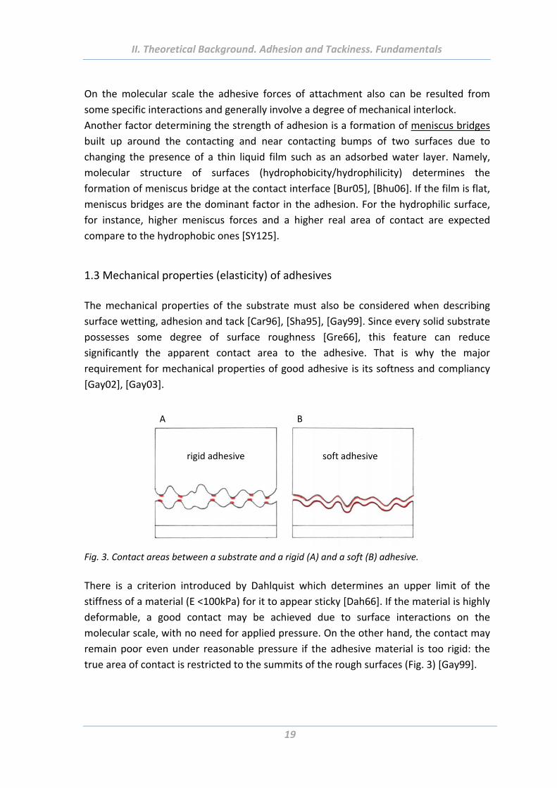
The mechanical properties of the substrate must also be considered when describing
surface wetting, adhesion and tack [Car96], [Sha95], [Gay99]. Since every solid substrate
possesses some degree of surface roughness [Gre66], this feature can reduce
significantly the apparent contact area to the adhesive. That is why the major
requirement for mechanical properties of good adhesive is its softness and compliancy
[Gay02], [Gay03].
A B
rigid adhesive soft adhesive
Fig. 3. Contact areas between a substrate and a rigid (A) and a soft (B) adhesive.
There is a criterion introduced by Dahlquist which determines an upper limit of the
stiffness of a material (E <100kPa) for it to appear sticky [Dah66]. If the material is highly
deformable, a good contact may be achieved due to surface interactions on the
molecular scale, with no need for applied pressure. On the other hand, the contact may
remain poor even under reasonable pressure if the adhesive material is too rigid: the
true area of contact is restricted to the summits of the rough surfaces (Fig. 3) [Gay99].
II. Theoretical Background. Adhesion and Tackiness. Fundamentals
20
1.4 Contact area (surface roughness)
Surface roughness is another important factor having direct influence on the strength of
adhesion between two surfaces [Gay02], [Cre02], [Cre96], [Gre07]. This influence is
however ambiguously and governed by mechanical properties of materials [Sve12].
If the adhesive is rigid, its contact area with a rough sample will be diminished. Even if
there are strong interactions on molecular scale, the tack will be reduced proportionally
to the reduction of contact area between the two surfaces [Gay02].
Another situation can be observed in the case of soft adhesives that are able to adjust
their form and fill the interstices of the rough surfaces. The contact area and therefore
the adhesion in‐between will increase [Sun05], [Gor05], [Rus99]. Furthermore, there is
another phenomenon that contributes to the strength of adhesion at the interface with
the soft adhesive. Tiny air bubbles can be trapped at the interface during the contact
and generate suction effects upon traction. Usual suction effects on the macroscopic
scale are achieved mechanically and the intimate contact is due interactions on the
molecular scale [Gay02].
Thus, in man‐made materials smoothening of the surface usually leads to improving of
adhesion, whereas increase of the surface roughness decreases the adhesion (at least
between rigid surfaces). On the other hand, natural systems use micro‐ and nano‐
structuring to achieve a just opposite effect, namely to provide extraordinary and yet
switchable adhesion [Aut00], [Cre99]. This is possible due to easiness of alignment of
such rough surfaces (containing high aspect ratio elastic micro‐needles oriented
perpendicularly to the surface) with various curved surfaces and also detach them from
the surface, when necessary. Development of the synthetic analogies imitating such
hierarchical structures is in full swing [Sit03], [Gre07], [Cam08], [Kam10], [Syn12].
The surface roughness can also be controlled through the melting phase transition in
polymer material. The surface of a semi crystalline polymer is rough with crystalline
lamellae protruding through the surface. Driving the polymer into the molten state
causes a dramatic reduction in the surface roughness. This is particularly well illustrated
by temperature switchable adhesives whose softness and consequently, roughness can
be made to vary significantly over a narrow temperature range [Cre99]. In the molten
state, the contact area between the two bodies will, in general, increase, thereby
increasing the adhesion. Thus, by using a simple melting phase transition, de Crevoisier
et al. [Cre99] achieved control over the surface and bulk mechanical properties of their
polymer and could delicate balance the factors that enhance and reduce adhesion
[Rus99].
Moreover, topographical patterns with different geometries can be formed using a
combination of colloidal lithography, etching, moulding and “drawing” techniques.
These surfaces could be used as substrates for binary brushes that facilitate switchable
properties. Using “classical” lithography methods well‐oriented periodic microstructures
II. Theoretical Background. Adhesion and Tackiness. Fundamentals
21
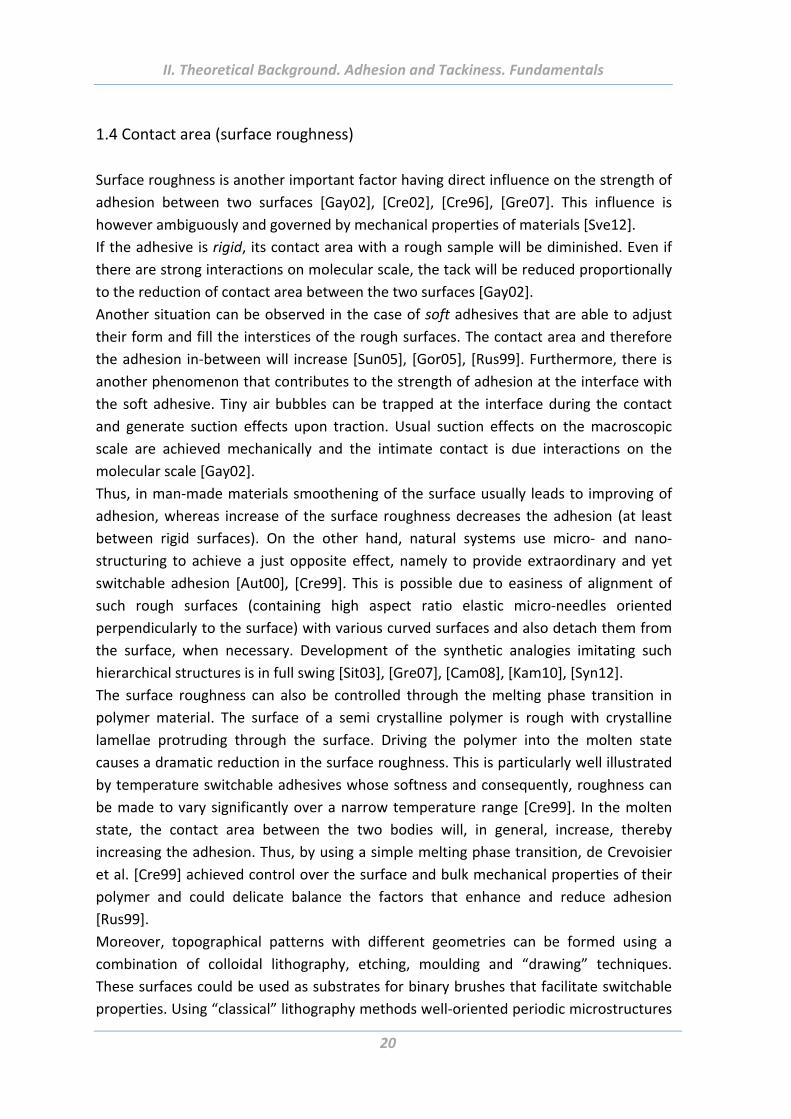
of different geometries and aspect ratio of asperities can be obtained [Syn07], [Cam08].
Colloidal lithography uses colloidal particles that can be easily assembled into highly
ordered structures by numerous methods [Syn05], [Syn06], [SYN125] (Fig. 4a). Mixing of
particles of different size can be used as well for the fabrication of more complex surface
structures (Fig. 4b).
Fig. 4. Representative topography images of regularly ordered particle layers: (a) AFM image of 1
μm particles assembly; (b) AFM image of mixed assembly from micro (2 μm) and sub micro (200
nm) colloidal particles [SYN125].
2. Switchable and adaptable adhesion
Two strategies of altering the adhesion properties are possible: simple switch and
continuous adaptation. Switchable adhesives are capable to switch their adhesion from
one state to another without any transitional state, whereas, adaptive adhesives change
its adhesion dynamically corresponding to influence of external stimuli or in compliance
with the properties of the surface to what they applied [SY125].
Switchability and adaptation are very prominent properties of various biological
molecular machines functioning in living organisms. Indeed, enzymes, RNA, ionic
channels, molecular motors, etc. act not always and not everywhere, but only in a
certain place and time. Being normally inactive, such machines transform (or reconform)
in their active form when obtain the corresponding managing signal (e.g., upon
interactions with ions, ATP, etc.). The switchability and adaptation of biological
elementary sub‐units are general principles of organization of matter, when it is
necessary to achieve, for instance, a long‐term co‐existence and function of a great
number otherwise incompatible species inside cells (e.g., RNA and RNase), or when it is
necessary to initiate or terminate the desired process in certain time. One prominent
example is the switching in multi‐weak‐interaction (hydrogen bonding) between the two
cooperative bistable states of haemoglobin (T state and R state) and oxygen which is a
II. Theoretical Background. Switchable and Adaptable Adhesion
22
fully reversible process and that facilitates O2 uptake in the lungs and release to organs
and tissues [Xia08]. Obviously, the switchability and adaptation are important
mechanisms for self‐regulation of extremely complicated systems.
In sharp contrast to natural organisms, man‐made materials are significantly less
“smart”. Further advances in material science impose requirements for dual surface
properties that frequently are in conflict: a given material, depending on the conditions
under which it is utilized, has to be hydrophobic or hydrophilic, acidic or basic,
conductive or insulating, adhesive or repellent, and be able to release or adsorb some
species. Investigation of the systems, able to change the surface properties began few
decades ago as response on rising interest to the “smart” or “intelligent” materials.
While there are a plenty of various examples of adhesive or non‐adhesive materials
most of them have fixed properties ‐ either tacky or non‐tacky ‐ that vary only slightly
with the surrounding conditions such as humidity or temperature. There are only few
examples of adhesives demonstrating change of adhesion in very broad range upon
contact with another material or to an environmental change [Jul03], [Kho02], [Ret05],
[Lah03], [Vis06].
Adhesion can be switched by two main factors: chemical functionality and topography.
Combination of these factors may lead to novel hierarchical structures with curious
properties [Syn12].
2.1 Switching of adhesion by chemical functionality
Control of intermolecular interactions such as formation of hydrogen bonds,
electrostatic or hydrophobic interactions which depend on chemical functionality of
materials, is used to manufacture smart materials with switchable and adaptive
adhesion properties [Syn12]. Such materials possess an ability to adjust their properties
to changing environmental conditions or external stimuli like: temperature, chemical
and biochemical stimuli, visible and UV light, pH, solvent, electric and magnetic stimuli.
1) Switchability of adhesion by temperature
Phase transitions in polymers
The first class of systems with temperature‐sensitive adhesion behaviour undergoes
transitions that occur with polymers itself: melting, crystallisation and liquid crystalline
phase transitions. There is a bulk transition between a highly ordered smectic and an
isotropic phase in such systems. A sharp change from a rigid to a soft behaviour
accompanying the transition affects the adhesion properties of the liquid crystalline
polymer. This transition behaviour was used to develop switchable adhesives by the
group of de Crevoisier [Cre99]. On each side of the phase transition, a different aspect of
II. Theoretical Background. Switchable and Adaptable Adhesion
23
the hybrid macromolecule becomes predominant and imprints its behaviour onto the
system. Through the side‐chain ordering, the smectic structure brings hardness and non‐
wettability. In contrast, in the isotropic phase, the presence of the backbone, which
connects the side chains together, allows for a strong dissipation that leads to both a
tacky behaviour and an ability to slow down the dynamics of wetting [Cre99], [Cho03].
This transition effect can be used to design versatile materials with highly flexible
properties that vary with temperature [Cre99].
An advantage of an ordering transition in a polymer containing alkyl and perfluoroalkyl
side chains to turn adhesion on and off has been shown. At low temperatures, the
perfluoroalkyl side chains (which have low surface energy) segregate to the surface. The
polymer is crystalline and has a fixed structure. At elevated temperatures, crystal
melting imparts mobility to the polymer such that it can respond to external stimuli. If a
hydrocarbon is brought in contact with the surface, a surface rearrangement occurs,
moving the alkyl segments to and the perfluoroalkyl segments away from the interface.
A delicate balance between factors that enhance and reduce tack gives rise to a
maximum in the tack over a very narrow temperature range. It is, of course, no accident
that the phase transition in the work of de Crevoisier et al. occurs at 35°C, slightly below
body temperature. By altering the length of the pendant side chains on the polymer, the
transition temperature can be fine‐tuned further.
Second approach for design glues with fickle stickiness was suggested by Ferguson and
Khongtong [Kho02], [Kho01]. They used oxidized cross‐linked 1,4‐polybutadiene (1,4‐
PBD‐ox). It was suggested that the thermoresponsive adhesion of a polymer–metal
interface (i.e. PBD‐ox/Al) arises from rubber elasticity in the interfacial region of the
polymer: at room temperature the functional groups of polymer strive to contact with
the aluminium (oxide). It is facilitated by stretching of the polymer chains out of their
random coil conformations, thus reducing the entropy in that region of the polymer.
Due to this, there are strong adhesive joints at room temperature. When the material is
heated, the polymer chains of the rubber contract, pulling aluminium‐loving carboxylic
acid groups away from the surface. As a result, the bond between the metal and the
polymer loosens such that the adhesion between the two surfaces is 44% less at 80°C
than it is at room temperature. After the rubbery glue returns to cooler temperatures, it
regains its former sticking prowess, although slowly. It takes approximately forty hours
to recover the initial level of adhesion, and this reversibility persists through multiple
heating and cooling cycles.
Another example of switchable adhesives uses a phase transition of admixed additives.
This principle is applied in the technology known as ‘‘Warm‐Off’’ [Chi01], [Cla93]. The
additive in this case is a side chain crystallisable polymer which is intimately mixed in the
crystalline state with a pressure‐sensitive adhesive (PSA) [Cre02] prior to spreading on
the backing. With growing ambient temperature, the additive will melt through a
II. Theoretical Background. Switchable and Adaptable Adhesion
24
mechanism which probably involves a mobile weak layer. The adhesion of the dressing
reduces considerably, around 90% from the peel strength measured before heating. So,
the adhesive can be removed cleanly, retaining little of the outer surface of the skin and
also releasing from hairs [Cla93], [Syn12].
An opposite principle, namely “Cool‐Off”, proposed by Clarke et al. [Cra93] implies
materials which become non‐adhesive at low temperatures. In this technology, a
conventional acrylic PSA is chemically modified by introducing long pendant side chains.
These chains have an ability to crystallise and melt at well‐defined temperatures. When
the side chains are molten, the adhesive behaves as a PSA. When crystalline, the
adhesive molecules are restrained (physical cross‐linking) and the adhesive mass
becomes hard, waxy and non‐tacky solid thus demonstrating low peel strength [Chi01],
[Cla93], [Syn12].
Phase transition in polymer solutions (LCST polymers)
Polymers which demonstrate LCST (Low Critical Solution Temperature) behaviour in an
aqueous environment are employed to design reversibly switchable adhesives. Well‐
known and the most widely studied system in this category is PNIPAM – poly(N‐
isopropylacrylamide). PNIPAM exhibits thermally responsive switching between
hydrophilicity and hydrophobicity. This effect is explained by the competition between
intermolecular and intramolecular hydrogen bonding below and above the LCST of
about 32‐33°C. At temperatures below the LCST, the predominantly intermolecular
hydrogen bonding between the PNIPAM chains and water molecules contributes to the
hydrophilicity of PNIPAM film, the polymer is in an extended, solvent‐swelled
conformation. At temperatures above the LCST, the polymer undergoes a phase
transition, the solvent is excluded, intramolecular hydrogen bonding in the PNIPAM
chains results in a compact and collapsed conformation of PNIPAM chains. It makes
difficult for the hydrophilic C=O and N‐H groups to interact with water molecules. Thus,
the hydrophobic interactions become predominant [Sun04], [Gil04], [Lin99], [Lee10],
Ala05. Moreover, above the LCST, PNIPAM coagulates also due to the hydrophobic
interactions. When the temperature is below the LCST, the hydrophobic isopropyl
groups in PNIPAM molecule should be embedded into the central part of molecule and
the hydrophilic C=O and NH groups in molecule are dominantly exposed to the outer
layer to contact with water to achieve higher composition of intermolecular hydrogen
bonding. When the temperature goes beyond the LCST, the hydrophobic isopropyl
groups are exposed to outer layer to form hydrophobic effect. So, the aggregation
phenomenon of PNIPAM might be attributable to both the intramolecular interactions
and the hydrophobic interactions [Lin99]. The thin films of PNIPAM are widely used for
temperature regulation of adhesion of proteins and cells.
Another class of biologically inspired thermoresponsive molecules is based on elastin‐
like polypeptides (ELPs) [Hyu04]. The molecules are water‐soluble at lower
II. Theoretical Background. Switchable and Adaptable Adhesion
25
temperatures but reversibly aggregate at elevated temperatures. The switching can be
induced by changes in temperature, pH, or ionic strength. Elastin‐like polypeptides have
been micropatterned to capture and to release other proteins fused to ELPs via
hydrophobic interactions upon transition [Nat03].
Fery et al. [Kes10] investigated the interaction forces between a native and a protein‐
coated probe and the thermoresponsive copolymer poly(2‐(2‐methoxyethoxy)ethyl
methacrylate‐co‐oligo(ethylene glycol) methacrylate) [P(MEO2MA‐co‐OEGMA)]‐coated
surfaces using a colloidal probe technique. The sharp transition in adhesion properties
was observed while passing though LCST and back. The system was switched many times
without a loss of adhesive performance.
Recently, Synytska et al. [Syn10], [Sve11] compared switchable adhesion behaviour of
thermoresponsive polymer brushes with different architectures based on PNIPAM and
polyethylene glycol polymers having LCSTs around 33°C. Temperature dependent
adhesion measurements in water on flat and rough surfaces have been performed. As it
was found, the synthesized via ATRP polymer brushes are completely non‐adhesive
below LCST and become adhesive at elevated temperatures. This behaviour was
independent of substrate roughness, the geometry and hydrophobicity/hydrophilicity of
the AFM probe. Moreover, the adhesion forces show full reversibility and repeatability.
Amongst the other important polymers undergo phase transition in solutions are poly(N‐
vinylcaprolactam), poly(propylene oxide), polyacrylamide, and polypeptides [Ala05].
2) Switchability of adhesion by solvent
The successful control of wettability of a self‐adapted polymer systems by exposing
them to different solvents was reported [Min03a]. The heterogeneous binary polymer
brushes were sensitive to toluene, ethanol, and water. The adaptive behaviour of the
polymer chains was amplified by the microscale roughness of the material. As a result,
the wettability of the mixed brushes could be switched from complete superhydrophilic
to superhydrophobic states.
The group of Minko has recently fabricated adaptive systems made of biocompatible
and biodegradable polymer brushes ‐ polyethylene glycol (PEG) and
polydimethylsiloxane (PDMS) [She08]. These brushes are widely used in medicine, food
industry and cosmetics. At room temperature these polymers have very mobile chains
because of low glass transition temperature (Tg) and they are able to immediately adapt
their properties to changes in environmental conditions. It was demonstrated that
PDMS‐PEG brushes exhibit low adhesion in both wet and dry states.
Müller et al. synthesized core–shell cylindrical polymer brushes with poly(t‐butyl
acrylate)‐b‐poly(n‐butyl acrylate), that were hydrolysed afterwards [Zha03]. Due to the
responsive nature of the PAA blocks toward different kinds of solvent, conformational
transitions were observed as a function of solvent quality.
II. Theoretical Background. Switchable and Adaptable Adhesion
26
Fischer and Schmidt made cylindrical brushes with PS side chains and studied solvent‐
induced length variation of the molecular brushes [Fis01]. They found that the lengths of
the backbone and side chains become shorter in a poor solvent as compared to a good
solvent. It is argued that the repulsion of the side chains represents the extension force,
which acts against the entropic contraction force of the main chain.
The adhesive properties of binary heterogeneous polymer brushes made from end‐
functionalised polystyrene (PS) and poly(2‐vinylpyridine) (P2VP) chains have been
investigated by Creton et al [Ret06], [Ret05]. The adhesion and wetting properties can
be reversibly switched by exposure of the system to selective solvents for PS (toluene)
and for P2VP (acidic water).
3) Switchability of adhesion by pH
Polyelectrolyte brushes tethered to surfaces are garnered increasing interest since they
can reversibly alternate between different polymer brush conformations, from collapsed
and extended states, and, as a consequence, gain control over surface properties such as
wettability, hydration, and stiffness [Moy05]. The swelling behaviour of polyelectrolyte
brushes is to a large extent governed by electrostatic interactions and the osmotic
pressure of the counterions. Several reviews describing the possibilities in this field have
been recently published [Luz04], [Min06], [Luz08], [Tok09].
One of the most common systems in polyelectrolyte polymer brushes utilizes acrylic acid
[Ayr07]. The expansion of the poly(acrylic acid) brush upon addition of base was
described as an example of the well‐known polyelectrolyte effect. The swelling
behaviour of a weak polyelectrolyte brush poly(methacrylic acid) in water as a function
of pH and salt concentration has been also investigated [Bie02].
The pH‐sensitive system was made by the group of M. Geoghegan [Spi07]. They
demonstrated how two surfaces, one consisted of polyacid gel and another – a polybase
grafted to a silicon substrate, stick together and separate in response to pH value.
Possible applications of such surfaces pairs include microelectromagnetic components
(actuators), components for microfluidic systems, or carries for pharmacological agents
that could release their cargo under specific physiological conditions.
4) Photo‐responsive surfaces
A photo switchable molecule can be converted from one form to another with light of
one wavelength and can either revert thermally to the original state or can be reverted
by irradiation with light of a different wavelength. The more commonly employed and
most‐studied classes of photo switchable molecular systems include: fulgides,
azobenzenes, spiropyrans, overcrowded alkenes, azulenes, alkylidenecycloalkanones,
diarylethenes [Bro09]. Spiropyran is reversibly changed by UV irradiation from the more
hydrophobic spiro conformation to the polar, hydrophilic zwitterionicmerocyanine
II. Theoretical Background. Switchable and Adaptable Adhesion
27
conformation. The reverse isomerisation can be triggered by irradiation with visible light
[Hig04].
The other approach by Edahiro et al. [Eda05] involved the use of a polymer material
composed of PNIPAM having spiropyranchromophores as side chains to develop a
reversible photo‐responsive culture surface [Men08].
More recently, light‐induced shape‐memory polymers have been reported [Len05],
[Jia06]. These materials can be deformed and temporarily fixed in a new shape. The
polymers can change from its flat ribbon‐like structure to a tight coil, then back to a
ribbon, in response to light irradiation. Such polymers are composed of an elastic
polymer network and a molecular switch, which determines their permanent shape and
forms reversible crosslinks upon photostimulus, respectively [Len05], [Yos08].
Light switchable adhesives (LSA) are the special kind of switchable adhesives based on
control of mechanical properties. These adhesives are composed of a functionalised
methacrylate copolymer mixed with a photoinitiator activated by visible light. The
photoinitiator induces a chain reticulation that decreases the peel strength of the
adhesive and allows it to get away from the substrate when exposed to light [Boy01].
5) Chemically or biochemically‐responsive surfaces
Enzyme‐triggered activation of surfaces shows great promise as a method for altering
surface properties in a controlled manner [Uli06]. Ulijn et al. [Tod07] reported a strategy
which could enzymatically switch polymer surfaces from a state that prevented cell
adhesion to another state in which cell adhesion and spreading were promoted.
Another example was shown by the group of Mrksich [Mrk03], gold surfaces carrying
modified PEG‐4‐hydroxyphenyl valerate could be switched enzymatically from a redox
inactive surface to a redox active surface by a deacylation reaction, either using the free
enzyme or a engineered cell line that expressed this enzyme at the cell surface, thereby
providing a way to interface cell behaviour with electrochemistry.
6) Electrically‐responsive surfaces
An electrically conducting polymer is generally comprised of a conjugated polymer chain
with π electrons delocalised along the backbone, yielding a semiconducting polymer that
can be reversibly tuned through doping, an oxidation/reduction process where charge
carriers are introduced to the polymeric backbone either chemically or
electrochemically. Poly(N‐methylpyrrolylium) poly(styrenesulfonate) (PMP+PSS‐) [Mil87]
and polypyrrole [Geo06] are particular interesting examples of electrically‐switchable
surfaces.
7) Magneto‐responsive surfaces
Magnetic field sensitive polymer gels have been developed [Gil04], [Baw09], [Sza98],
[Zri00]. This magneto‐controlled elastic medium, called ferrogel, ferrofluid, or magnetic
II. Theoretical Background. Switchable and Adaptable Adhesion
28
fluid, is a diluted ensemble of noninteracting magnetic nanoparticles (with a typical size
of ≈10 nm) homogeneously distributed in a polymer network. In ferrogels the magnetic
and high elastic properties are coupled. As a result significant shape distortion occurs
instantaneously and disappears abruptly when an external magnetic field is applied or
removed.
For example, magnetic particles of colloidal size have been introduced into chemically
cross‐linked poly(N‐isopropylacrylamide) and poly(vinyl alcohol) hydrogels [Zri00]. The
influence of uniform and non‐uniform fields has been studied. In uniform magnetic
fields the gel beads form straight chainlike structures, whereas in nonhomogeneous
fields the beads aggregates due to the magnetophoretic force directed to the highest
field intensity. The ability of magnetic field sensitive gels to undergo a quick controllable
change of shape can be used to create an artificially designed system possessing sensor
and actuator functions internally in the gel itself. The peculiar magnetoelastic properties
may be used to create a wide range of motion and to control the shape change and
movement, which are smooth and gentle similar to those observed in a muscle. Thus,
application of magnetic field sensitive gels as a soft actuator for robots and other
devices has special interest. Unlike in metallic machine systems, devices made of gels
work without noise, heat evolution, and exhaustion [Sza98].
8) Multi‐responsive surfaces
Although many stimuli‐responsive surfaces exhibiting reversible properties have been
fabricated, they are only responsive to one kind of external stimuli. For some
applications however dual/multiple‐responsive materials are required. The most
common are the dual‐thermoresponsive polymers, showing LCST, UCST or both,
combined with pH‐responsiveness. In some cases, thermal response can be combined
with magnetic or electric responsiveness, usually applied to hydrogels or nanoparticles
[Lee10].
A copolymer that contains temperature‐sensitive PNIPAM and pH‐sensitive poly(acrylic
acid) (PAA) was fabricated [Xia06]. Under external stimuli the copolymer demonstrates
dual response. Reversible switching of the systems on rough surfaces between
superhydrophilicity and superhydrophobicity occurs in both a narrow temperature range
of about 10°C and a relatively broad pH range of 9. This behaviour can mainly be
attributed to reversible changes in hydrogen bonding between the two polymer
components, PNIPAM and PAA, and water.
Recently, superhydrophobic poly(3‐hexylthiophene)‐polyacrylonitrile (PANI‐PAN) coaxial
nanofibers were fabricated through combination of electrospinning and polymerization.
This nanofibers show a chemical dual‐responsive surface in wettability, which can be
controlled by adjusting the acid–base and redox properties of probe solution [Zhu07]. A
reversible conversion between superhydrophobicity and superhydrophilicity was
achieved.
II. Theoretical Background. Switchable and Adaptable Adhesion
29
Also multi‐stimuli‐responsive surfaces, which reversibly switch between
superhydrophilicity and superhydrophobicity in response to glucose, temperature, and
pH, were fabricated [Xia07]. Temperature and pH sensitive PNIPAM was included in the
surface as well as glucose‐sensitive poly(acrylamidophenylboronic acid) (PPBA), which
forms stable complexes with glucose via its borate groups [Xia08].
2.2 Switching of adhesion by surface topography
Many insects and animals, such as flies, spiders, and geckos have an amazing ability to
firmly attach to and easily detach from almost any kind of surface and thus to move
along vertical walls and even ceilings. This peculiar locomotion is possible due to
hierarchically arranged structure of the animal pads: they are covered with long micro‐
to nano‐sized hairs with characteristic geometries and mechanical properties [Aut00],
[Aut02], [Arz03]. These structures facilitate conditions for appearance of van der Waals
and capillary forces of great efficiency and thus play a crucial role in the phenomenon
[Arz03].
Nowadays there is a plenty of publications that describe structuring methods applied to
generate gecko‐like fibrillar substrates with different geometries and dimensions.
Particular attention is paid to effect of surface topography and roughness on wettability
as well as to design of rough surfaces with switchable wetting properties [Que03],
[Für05], [Boe10], [Xia08].
The design and fabrication involves patterning methods, which can be largely
transferred from microelectronic and micromechanical processing [Cam08].
Microfibrillar surfaces are mainly produced by soft‐lithography, photolithography using
an SU‐8 photoresist [Lam07], [Cro05], [Gre07], [Gla07] but also by indenting a wax
surface with an atomic force microscope tip [Sit03] or by laser ablation of a metallic
surface [Per04].
Micro‐ and nanosized fibrils with flat tips and also more complex geometries such as
spatula‐ended fibrils, tilted fibrils, or hierarchical fibrillar structures have been obtained
as well [Lam07], [Gre07], [Cro05], [Sit03], [Aks07], [Jeo06]. Together with different
patterning methods, micro‐ and nanoscaled rough surfaces can be also fabricated from
assemblies with colloidal particles [Soe03], [Shi04], [Min05a], [Zha04], [Zha05a], [Ma06],
[Sve11]. Recent reports deal with structured responsive materials in order to
incorporate the reversible and adaptive character of gecko adhesion to artificial systems
[Kus07], [Kam10].
The first article describing structured surfaces with switchable adhesion behaviour was
published by Del Campo and co‐workers [Red07]. The materials were made of the shape
memory thermoplastics known for their ability to recover the original permanent shape
from a temporary one via reheating the material about the glass transition temperature
of the polymer.
II. Theoretical Background. Switchable and Adaptable Adhesion
30
Other system consisted of a shape memory polymer (SMP) layer and a smooth, non‐
structured, dry adhesive layer has been fabricated by Xie and Xiao [Xie08]. The material
showed a slight curvature, which, in combination with the rigidity of the SMP layer,
resulted in poor adhesion at room temperature. When the system is heated above the
transition temperature, the adhesive deforms and comes into good contact with the test
probe. After cooling to room temperature the deformed shape of the adhesive is
maintained due to the SMP layer and the adhesion is retained. Upon heating the SMP
returned to its original curved structure, and the contact area became small and the
adhesive is thus released.
Since then, systems which respond to external stimuli, such as temperature, magnetic
and electric fields, mechanical stretching, pneumatic pressure and preload, have been
developed. In general, the expose to external field results in change in the topographical
design of a surface that in turn influences the final adhesion performance. The adhesion
switch is achieved in many cases by reversible maximization and minimization of the
contact area upon influence of external stimuli.
Magnetic and electric switching
It was reported [Nor08] about the biomimetic systems with switchable adhesion
behaviour able to undergo a reversible conformational change in magnetic field. They
are composed of 10µm wide and 130µm long flexible nickel paddles coated by 200nm
diameter aligned vertical polymeric nanorods (analogous to the hierarchical structure of
gecko’s pads). When subjected to a magnetic field the paddles reorient themselves
rotating away from the counter‐surface, reducing the contact area of sticking surface,
consequently, decreasing the adhesion force (by about a factor of 40 comparatively with
an adhesive state without the magnetic field). The adhesion behaviour of presented
systems is complete reversible allowing switching the adhesion countless times, that is
advantageous over approaches based on shape memory polymers. The materials have
perspectives to be used as everyday consumer products such as latching and fastening
systems, as well as for high‐tech applications, like microrobotics applied to
extraterrestrial surfaces or harsh climates otherwise not accessible to man [Nor08].
An approach based on an electronically switchable capillary adhesion device was
presented. Inspired by a leaf beetle able to generate adhesion forces exceeding 100
times its body weight, Vogel and Steen [Vog10] made their material with the surface
tension force that arises from a large number of small liquid bridges that can be quickly
made or broken with electronic control. Liquid was pumped through a hole into the
device until contact is made and a liquid bridge is formed between the device and the
substrate. In releasing, liquid was pumped back into the device until the bridge became
unstable and broke.
II. Theoretical Background. Switchable and Adaptable Adhesion
31
Mechanical switching
Another group of materials with switchable adhesion using mechanics as stimulus was
reported. Suh and co‐workers [Jeo10] have utilised a wrinkled polydimethylsiloxane
(PDMS) sheet with a thickness of 1 mm with built‐in micropillars. The wrinkles were
generated through to oxygen plasma treatment of the extended PDMS sheet and
subsequent strain release. An active, dynamic control of normal and shear adhesion was
achieved: relatively strong normal and shear forces were obtained for a fully extended
(strained) PDMS sheet, whereas the forces could be rapidly reduced to nearly zero once
the strain was released. Durability tests showed the ability of such systems to be
switched in more than 100 attachment and detachment cycles.
Nadermann et al. showed structures with a fibrillar PDMS surface terminated by a
continuous film that can be switched between two metastable states. In the first one,
the film is stretched and held up by fibrils, it demonstrates strong adhesion compared to
an unstructured flat PDMS. In the second state, the film collapses and adheres to the
substrate between fibrils. To switch the system, the terminal film was then sucked in
using air pressure or mechanical pressure. As a result, the surface gets rough surface
composed of periodic arrays of bumps. The contact area and also the adhesion force will
decrease. The surface can be switched again by removal of the pressure or through
blowing up the film; the properties will be recovered [Nad10].
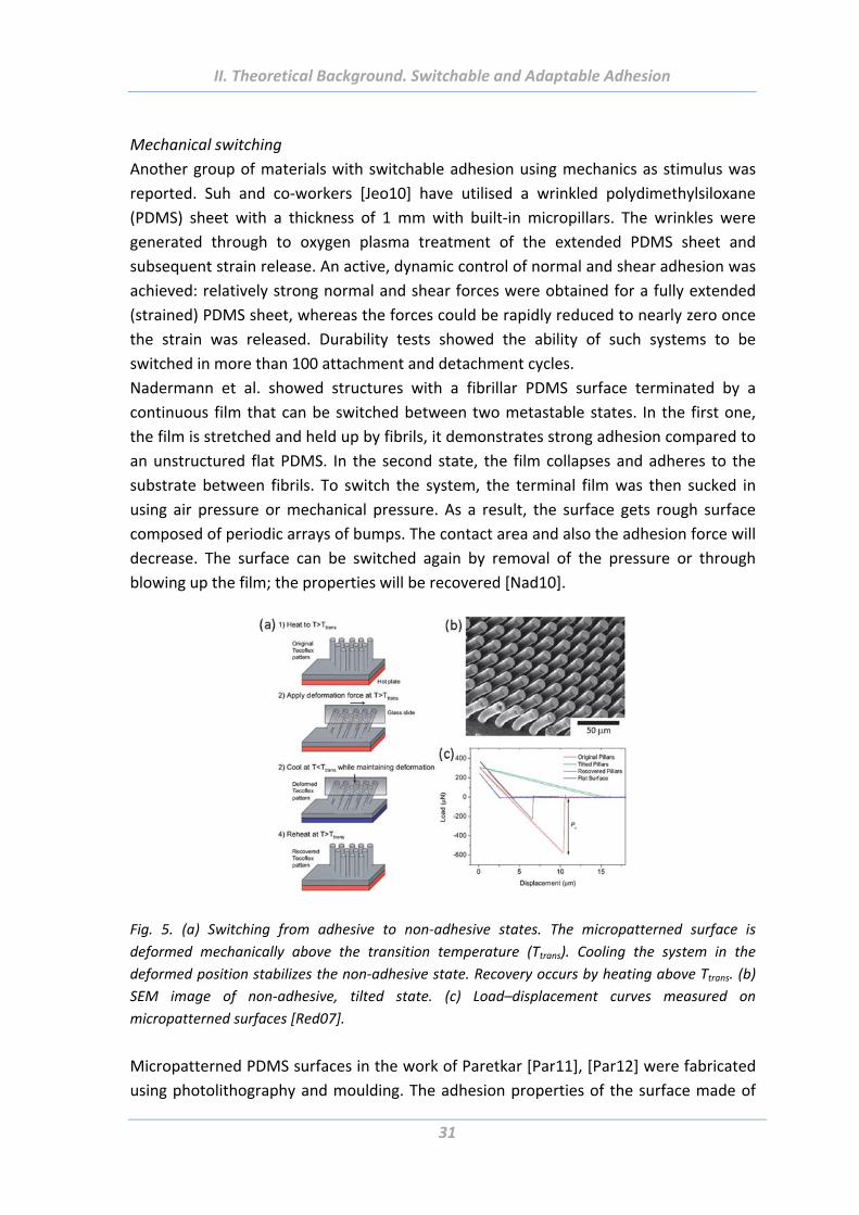
Fig. 5. (a) Switching from adhesive to non‐adhesive states. The micropatterned surface is
deformed mechanically above the transition temperature (Ttrans). Cooling the system in the
deformed position stabilizes the non‐adhesive state. Recovery occurs by heating above Ttrans. (b)
SEM image of non‐adhesive, tilted state. (c) Load–displacement curves measured on
micropatterned surfaces [Red07].
Micropatterned PDMS surfaces in the work of Paretkar [Par11], [Par12] were fabricated
using photolithography and moulding. The adhesion properties of the surface made of
II. Theoretical Background. Switchable and Adaptable Adhesion
32
30 µm length and 10 µm diameter fibrils can be switch reversibly with a compressive
preload as an external stimulus (Fig. 5). Adhesion forces were measured with a flat
probe as a function of preload. At low or moderate compression, there is a good contact
between the surfaces, the adhesion force is big, whereas at high compressive preloads
adhesion dropped to very low values. It can be explained by bending and buckling of the
fibrils under high pressure and a subsequent loose of contact with the probe surface.
The elasticity of PDMS contributes to the pillar recovery to regain the upright position
upon removal of preload enabling repeatability of the switch. The switch can be
controlled by fibril aspect ratio, tip shape and alignment to the test surface. The folding
of end flaps at the tip of the fibrils facilitates larger difference in adhesion strength
between the adhesive and non‐adhesive states [Par12].
Pressure modulated adhesion between flat, stiff objects and elastomeric surfaces with
sharp pyramidal features was presented [Kim10]. Rogers and co‐workers fabricated
elastomeric micropyramidal structures on a square surface, specifically designed for
transfer printing applications. To peak up some object the pressure was applied to
deform and collapse the region between the pyramids and make a big contact area with
the object. After peak‐up the sample relaxes and the picked‐up object has a contact just
with the pyramids. So the contact area is quite small that makes it possible to detach the
object easily by gently pressing it on a receiver surface. In such a way, the adhesion
strength could be switched by more than three orders of magnitude in a reversible
fashion.
3. Stimuli‐responsive materials and polymer brushes A number of smart stimuli‐responsive materials have been developed that are able to
alter their properties upon exposure to internal or external stimuli [Boy01], Ala05, [Min06], [Bun08], [Men08], [Yos08], [Bro09], [Nan10], [Lee10], [Stu10]. To minimize the
free energy of the system such responsive systems undergo following transitions: from
wetting to non‐wetting, from adhesive to non‐adhesive, from adsorbing to non‐
adsorbing, from attractive to repulsive, etc.
To provide surfaces with desired functions and properties, grafting of stimuli‐responsive
polymers on the surface is a widely used method. Surfaces modified with two or more
thermodynamically incompatible polymers represent unique responsive properties
[Sid99]. The attached chains are capable of molecular motions and micro‐phase
segregation in response to external environment [Sid99], [Min02b], [Min03b]. Upon
exposure to stimuli which are selective for the components of the brush the
reorganization of the structure occurs, for example, through migration of solvated
polymer which migrates preferentially at the top of the brush and dictates the surface
properties of the whole film [Ion03], [Hou03] (Fig. 6). Experimental and theoretical work
II. Theoretical Background. Stimuli‐Responsive Materials and Polymer Brushes
33
demonstrated that lateral versus vertical reorganization within the polymer layer is the
origin of this switching behaviour.
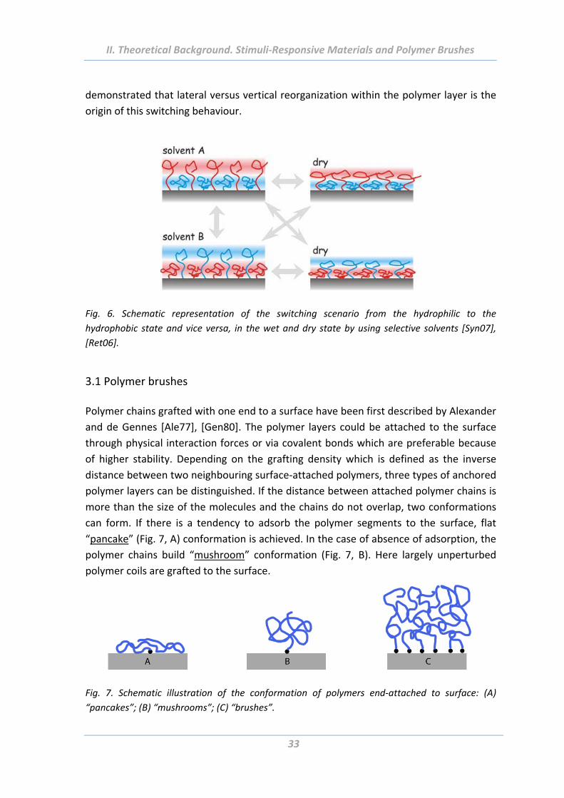
Fig. 6. Schematic representation of the switching scenario from the hydrophilic to the
hydrophobic state and vice versa, in the wet and dry state by using selective solvents [Syn07],
[Ret06].
3.1 Polymer brushes
Polymer chains grafted with one end to a surface have been first described by Alexander
and de Gennes [Ale77], [Gen80]. The polymer layers could be attached to the surface
through physical interaction forces or via covalent bonds which are preferable because
of higher stability. Depending on the grafting density which is defined as the inverse
distance between two neighbouring surface‐attached polymers, three types of anchored
polymer layers can be distinguished. If the distance between attached polymer chains is
more than the size of the molecules and the chains do not overlap, two conformations
can form. If there is a tendency to adsorb the polymer segments to the surface, flat
“pancake” (Fig. 7, A) conformation is achieved. In the case of absence of adsorption, the
polymer chains build “mushroom” conformation (Fig. 7, B). Here largely unperturbed
polymer coils are grafted to the surface.
Fig. 7. Schematic illustration of the conformation of polymers end‐attached to surface: (A)
“pancakes”; (B) “mushrooms”; (C) “brushes”.
II. Theoretical Background. Stimuli‐Responsive Materials and Polymer Brushes
34
Interesting effects are observed when the grafting density increases. If the distance
between grafted chains is smaller than an average end‐to‐end distance of the polymer
chain, they start to overlap and interact with each other. The polymer chains stretch
along the direction normal to the grafting surface because of the excluded volume effect
and the necessity to minimize the interaction energy between polymer segments
[Gen80], [Ale77], [Zha00]. The layer of the grafted chains assumes so called “brush”
conformation (Fig. 7, C). The conformation is determined by the energy balance
between the repulsion interactions between the polymer segments and elastic free
energy of the stretched chain. This leads to a new equilibrium at a higher energetic state
than that of isolated coils and this new behaviour of the stretched polymers differs
considerably from that of flexible polymers in solution where chains adopt a random‐
walk configuration [Zha00]. The more is the grafting density of the polymer chains on
the surface, the more stretching is observed and as a result, the thickness of the
polymer brushes increases [Rüh04], [Hou05], [Min02a].
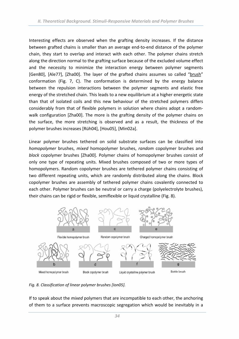
Linear polymer brushes tethered on solid substrate surfaces can be classified into
homopolymer brushes, mixed homopolymer brushes, random copolymer brushes and
block copolymer brushes [Zha00]. Polymer chains of homopolymer brushes consist of
only one type of repeating units. Mixed brushes composed of two or more types of
homopolymers. Random copolymer brushes are tethered polymer chains consisting of
two different repeating units, which are randomly distributed along the chains. Block
copolymer brushes are assembly of tethered polymer chains covalently connected to
each other. Polymer brushes can be neutral or carry a charge (polyelectrolyte brushes),
their chains can be rigid or flexible, semiflexible or liquid crystalline (Fig. 8).
Fig. 8. Classification of linear polymer brushes [Ion05].
If to speak about the mixed polymers that are incompatible to each other, the anchoring
of them to a surface prevents macroscopic segregation which would be inevitably in a
II. Theoretical Background. Stimuli‐Responsive Materials and Polymer Brushes
35
solution. The phase behaviour of such polymer brushes is determined by a competition
of the mixing entropy, which favours homogeneously mixed state, and the interaction
energy, which is reduced by spatial separation of the incompatible polymers [Mar91].
Cylindrical polymer brushes are assembly of tethered polymer chains that consist of a
backbone and side chains having different nature. These polymer brushes have the same
number of side chains as degree of polymerization of the main chain. Intramolecular
excluded‐volume interactions between side chains densely grafted to the backbone
contribute to the formation of the extremely extended conformation of the main chain.
Depending on the type of side chains, the cylindrical polymer brushes can be divided
into bottle‐brushes if the side chains are homopolymers, and core‐shell cylinders if the
side chains are block copolymers.
Intramolecular phase separation between two chemically different side chains
statistically or alternatingly attached to a backbone has been investigated theoretically
and in practise. For this a number of parameters such as the incompatibility between the
side chain molecules, the relative length of the side chains, flexibility/rigidity of the
backbone and the solvent quality with respect to the two different side chains have
been taken into account [Ste02], [Jon04], [Hsu07].
Influence of the solvent quality on statistical copolymacromonomers made from poly(2‐
vinyl pyridine) and poly(methyl methacrylate) macromonomers have been shown. The
system has different shapes ranging from wormlike to horseshoe or meander structures
when spin‐cast onto mica [Ste02].
It was even reported about the possibility of formation of Janus‐type phase‐separated
cylindrical brushes in solution, consisted of a rigid backbone and hetero side chains
[Tsu01], [Zha03], [Hsu07], [Iru08].
3.2 Grafting approaches
There are two well‐established routes for the fabrication of tethered polymer layers:
“grafting to” and ”grafting from” approaches.
In the “grafting to” method previously prepared polymer chains are used. They have end
functional groups which are able to form covalent bonds with reactive sites on the
surface of the substrate (Fig. 9). This method is very simple for generating polymer
layers with narrow molecular weight distribution. However there are several
disadvantages which limit the applicability of the “grafting to” procedure. Only relatively
simple polymer molecules can be surface‐attached by this method, because of the high
reactivity of the end‐functional groups which prevents the coexistence of most
functional groups in the polymer [Rüh04]. In addition, once the surface is significantly
covered with polymer chains the further attachment becomes more and more
complicated, because of a strong kinetic hindrance (the diffusion of further polymers
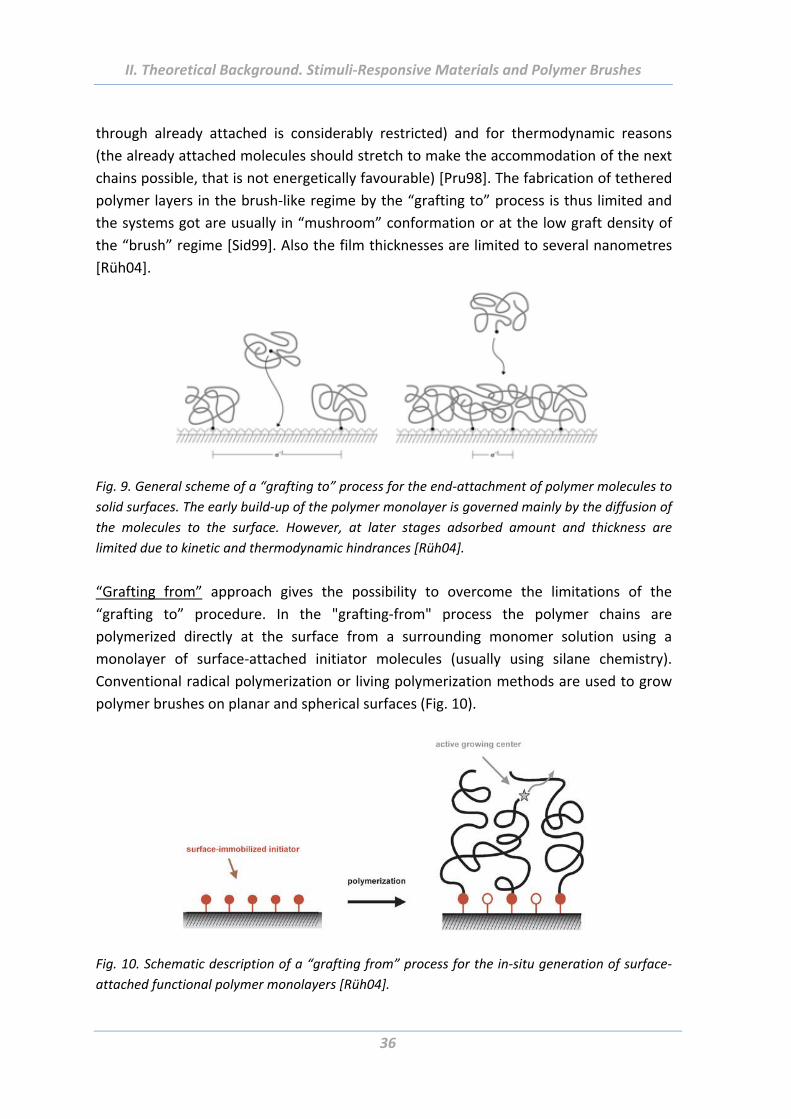
II. Theoretical Background. Stimuli‐Responsive Materials and Polymer Brushes
36
through already attached is considerably restricted) and for thermodynamic reasons
(the already attached molecules should stretch to make the accommodation of the next
chains possible, that is not energetically favourable) [Pru98]. The fabrication of tethered
polymer layers in the brush‐like regime by the “grafting to” process is thus limited and
the systems got are usually in “mushroom” conformation or at the low graft density of
the “brush” regime [Sid99]. Also the film thicknesses are limited to several nanometres
[Rüh04].
Fig. 9. General scheme of a “grafting to” process for the end‐attachment of polymer molecules to
solid surfaces. The early build‐up of the polymer monolayer is governed mainly by the diffusion of
the molecules to the surface. However, at later stages adsorbed amount and thickness are
limited due to kinetic and thermodynamic hindrances [Rüh04].
“Grafting from” approach gives the possibility to overcome the limitations of the
“grafting to” procedure. In the "grafting‐from" process the polymer chains are
polymerized directly at the surface from a surrounding monomer solution using a
monolayer of surface‐attached initiator molecules (usually using silane chemistry).
Conventional radical polymerization or living polymerization methods are used to grow
polymer brushes on planar and spherical surfaces (Fig. 10).
Fig. 10. Schematic description of a “grafting from” process for the in‐situ generation of surface‐
attached functional polymer monolayers [Rüh04].
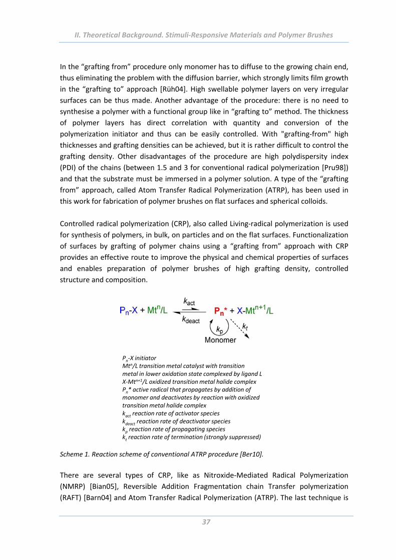
II. Theoretical Background. Stimuli‐Responsive Materials and Polymer Brushes
37
In the “grafting from” procedure only monomer has to diffuse to the growing chain end,
thus eliminating the problem with the diffusion barrier, which strongly limits film growth
in the “grafting to” approach [Rüh04]. High swellable polymer layers on very irregular
surfaces can be thus made. Another advantage of the procedure: there is no need to
synthesise a polymer with a functional group like in “grafting to” method. The thickness
of polymer layers has direct correlation with quantity and conversion of the
polymerization initiator and thus can be easily controlled. With "grafting‐from" high
thicknesses and grafting densities can be achieved, but it is rather difficult to control the
grafting density. Other disadvantages of the procedure are high polydispersity index
(PDI) of the chains (between 1.5 and 3 for conventional radical polymerization [Pru98])
and that the substrate must be immersed in a polymer solution. A type of the “grafting
from” approach, called Atom Transfer Radical Polymerization (ATRP), has been used in
this work for fabrication of polymer brushes on flat surfaces and spherical colloids.
Controlled radical polymerization (CRP), also called Living‐radical polymerization is used
for synthesis of polymers, in bulk, on particles and on the flat surfaces. Functionalization
of surfaces by grafting of polymer chains using a “grafting from” approach with CRP
provides an effective route to improve the physical and chemical properties of surfaces
and enables preparation of polymer brushes of high grafting density, controlled
structure and composition.
Pn‐X initiatorMtn/L transition metal catalyst with transitionmetal in lower oxidation state complexed by ligand LX‐Mtn+1/L oxidized transition metal halide complexPn* active radical that propagates by addition ofmonomer and deactivates by reaction with oxidizedtransition metal halide complexkact reaction rate of activator specieskdeact reaction rate of deactivator specieskp reaction rate of propagating specieskt reaction rate of termination (strongly suppressed)
Scheme 1. Reaction scheme of conventional ATRP procedure [Ber10].
There are several types of CRP, like as Nitroxide‐Mediated Radical Polymerization
(NMRP) [Bian05], Reversible Addition Fragmentation chain Transfer polymerization
(RAFT) [Barn04] and Atom Transfer Radical Polymerization (ATRP). The last technique is
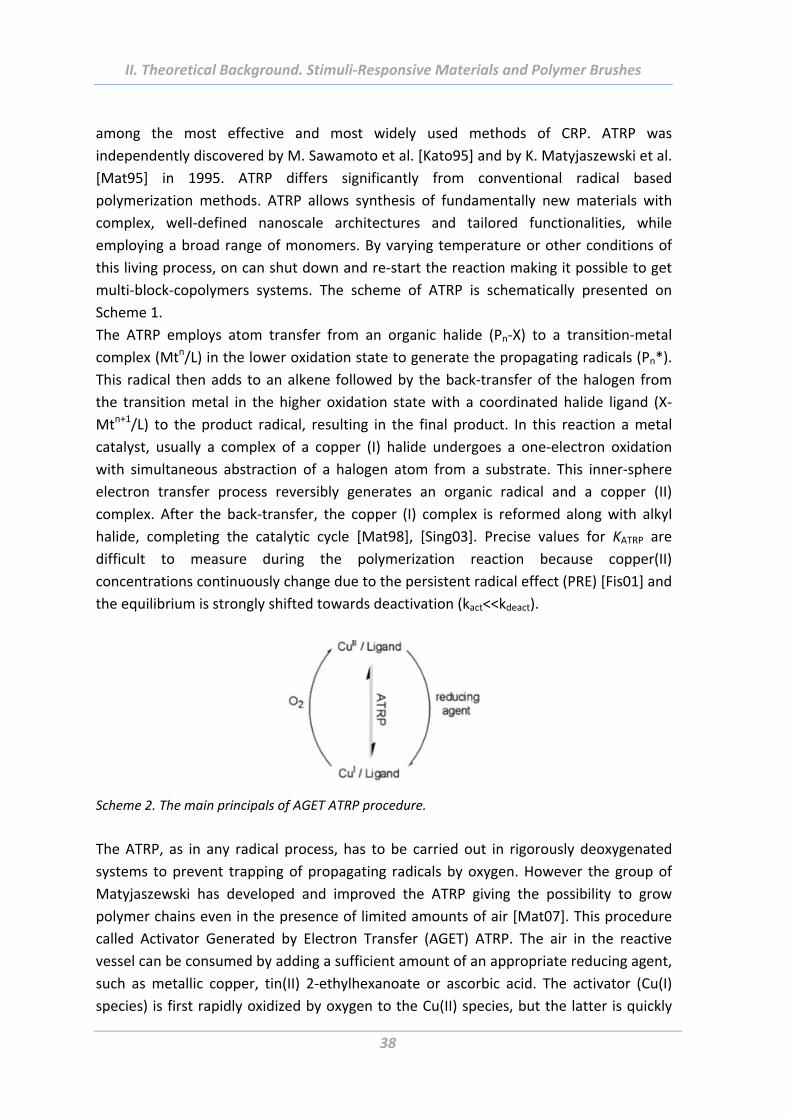
II. Theoretical Background. Stimuli‐Responsive Materials and Polymer Brushes
38
among the most effective and most widely used methods of CRP. ATRP was
independently discovered by M. Sawamoto et al. [Kato95] and by K. Matyjaszewski et al.
[Mat95] in 1995. ATRP differs significantly from conventional radical based
polymerization methods. ATRP allows synthesis of fundamentally new materials with
complex, well‐defined nanoscale architectures and tailored functionalities, while
employing a broad range of monomers. By varying temperature or other conditions of
this living process, on can shut down and re‐start the reaction making it possible to get
multi‐block‐copolymers systems. The scheme of ATRP is schematically presented on
Scheme 1.
The ATRP employs atom transfer from an organic halide (Pn‐X) to a transition‐metal
complex (Mtn/L) in the lower oxidation state to generate the propagating radicals (Pn*).
This radical then adds to an alkene followed by the back‐transfer of the halogen from
the transition metal in the higher oxidation state with a coordinated halide ligand (X‐
Mtn+1/L) to the product radical, resulting in the final product. In this reaction a metal
catalyst, usually a complex of a copper (I) halide undergoes a one‐electron oxidation
with simultaneous abstraction of a halogen atom from a substrate. This inner‐sphere
electron transfer process reversibly generates an organic radical and a copper (II)
complex. After the back‐transfer, the copper (I) complex is reformed along with alkyl
halide, completing the catalytic cycle [Mat98], [Sing03]. Precise values for KATRP are
difficult to measure during the polymerization reaction because copper(II)
concentrations continuously change due to the persistent radical effect (PRE) [Fis01] and
the equilibrium is strongly shifted towards deactivation (kact<<kdeact).
Scheme 2. The main principals of AGET ATRP procedure.
The ATRP, as in any radical process, has to be carried out in rigorously deoxygenated
systems to prevent trapping of propagating radicals by oxygen. However the group of
Matyjaszewski has developed and improved the ATRP giving the possibility to grow
polymer chains even in the presence of limited amounts of air [Mat07]. This procedure
called Activator Generated by Electron Transfer (AGET) ATRP. The air in the reactive
vessel can be consumed by adding a sufficient amount of an appropriate reducing agent,
such as metallic copper, tin(II) 2‐ethylhexanoate or ascorbic acid. The activator (Cu(I)
species) is first rapidly oxidized by oxygen to the Cu(II) species, but the latter is quickly
II. Theoretical Background. Stimuli‐Responsive Materials and Polymer Brushes
39
reduced to the Cu(I) state in the presence of a reducing agent (Scheme 2). This process
has been successfully used to prepare well‐defined products in organic media and also in
miniemulsion [Min05], [Jak05].
4. Application of adhesives with responsive and adaptive properties
The increasing need for “smartness” in biomedical and engineering materials has
generated a growing interest for synthetic polymers that exhibit environmentally
responsive adhesion behaviour [Lee10].
4.1 Biomedical applications Smart adhesives are very promising for a great variety of biomedical applications such as
wound dressings and bandages, immobilization devices, transdermal delivery devices,
biosensors, drug delivery, for bioseparation and tissue engineering [Nan10], [Ala05],
[Stu10], [Wis08], [Syn12], as well as for fabrication of micro(nano)‐electromechanical
systems (MEMS/NEMS), microfluidic devices and biomedical equipment [Del05],
[Gra04], [She08], [She09].
The light‐switchable adhesives have attracted interest to be applied as plasters [lum11].
Adhesives are very sticky in their normal state but lose their adhesion when exposed to
visible light that is advantageous for delicate surfaces like skin. The disadvantage of LSA
is that they can be switched only once. Pressure‐sensitive adhesives have been also used
to produce plasters [Chi01].
Thermoresponsive PNIPAM‐containing systems are widely used for adhesion of proteins,
cells and cell assemblies [Can05], [Aki04], [Men09]. In certain cases, cells and proteins
will adhere to the thermoresponsive PNIPAM films at physiological temperature (37°C),
and detach when the temperature is reduced to room temperature, i.e., below the LCST.
Also polymer films comprising photo‐responsive molecules such as spiropyran [Hig04]
represent attractive candidates for controlling protein and cell adhesion on surfaces.
For the same purpose, coatings composed of thermoresponsive side chain
oligo(ethylene glycol) have been fabricated by Laschewsky et al. [Wis08], [Kes10]. The
advantage of the system comparatively to PNIPAM coating is a better inherent
biocompatibility, reduction of nonspecific protein adsorption even above the LCST and
more effective control of cell adhesion.
Microfluidic devices are being developed to adsorb biological, organic, or inorganic
materials from solution, hold them, and release on command, facilitating separation,
purification, analysis, and delivery of substances [Hub03]. Wherever they are used, their
functioning is restricted by fouling. For many purposes (preconcentration, separation,
and sensing of analytes) the interfacial adsorption is however desired. Therefore, the
II. Theoretical Background. Application
40
microfluidic devices have to be switchable, to adhere and release substances on
demand. Thermally programmable protein capture and release has been achieved using
both PNIPAM [Hub03] and elastin films [Hyu04]. The PNIPAM was integrated into
microfluidic hot plate and could be switched between an antifouling hydrophilic state
below LCST and a protein‐adsorbing state that is more hydrophobic [Hub03].
Smart adhesives are also widely used in the field of drug‐delivery. The ability of drugs to
reach target tissues is limited by the body’s multiple barriers. To overcome them the
materials with responsive adhesion properties are used [Mit08], [Ori03], [Lan04]. Peppas
and co‐workers have developed polymers that swell in response to pH change. At low
pH values (like in stomach) they are collapsed but swell at higher pH’s, such as those
encountered in the upper small intestine where they can release the required
medicament [Tor02].
Multi‐responsive poly(NIPAM‐co‐PBA) polymer brushes are used for novel non‐invasive
glucose sensors and insulin self‐delivering systems for diabetic patients [Xia07], [Xia08].
Conducting [Geo06], [Ger02], [Zho89] and enzyme‐responsive [Mrk03] polymers layers
were also investigated for the purpose of drug delivery.
4.2 Engineering (non‐biomedical) applications There is a wide range of application of smart adhesives also for engineering purposes.
For example, as anti‐reflection, anti‐corrosion and anti‐icing coatings, for solar cells,
textiles, for drag reduction and sensors [Liu12].
A novel antifogging strategy for simultaneous self‐cleaning and antifogging materials
was proposed by Howarter et al. [How07] via stimuli‐responsive polymer brushes.
Perfluorinated end‐capped polyethylene glycol (f‐PEG) surfaces exhibited stimuli‐
responsive and simultaneously PEG‐like behaviour to water (hydrophilicity) and
fluorinated behaviour to oil (oleophobicity), which is a promising solution for self‐
cleaning anti‐fog coatings [How07].
Adhesives for industrial, consumer and military settings based on reversible adhesives
inspired by mussels and geckos hat been developed [Lee07], [Mes07]. The results of this
study are temporary adhesives – reusable tape that adhere equally well in wet and dry
conditions.
A synthetic gecko foot‐hair fabrication method was proposed by Sitti and Fearing [Sit03].
The dry adhesives made via nanomolding technique can be useful for future wall‐
climbing and surgical robots and also for other general dry adhesive applications.
Fluorinated coatings with order‐disorder structural transitions that tune the adhesive
and wettability properties of a material in the range of human body temperature
[Cre99] are suitable as responsive grips for sporting equipment such as baseball bats,
tennis racquets, and golf clubs, or for garments with cling.
II. Theoretical Background. Application
41
Gecko‐inspired synthetic microfiber arrays were fabricated with a non‐tacky stiff
polymer [Lee08], [Sch08]. The materials with directional adhesion can easy attach
(without requiring high pressure) and release. It could be also useful for sporting goods
or climbing robots where a controllable and reusable adhesive is needed.
Light‐switchable adhesives are useful for electronics, paper and graphics industries. They
are used as industrial tape, de‐bond on demand adhesive foil, tamper‐proof labels and
residual‐free labels [lum11].
The demand for such “smart” systems for engineering, biomedical, food and cosmetics
industries grows continuously. This is a steadily expanding area of research and certain
success has been already achieved. Nevertheless, there is still a chasm between the
natural and the man‐made materials, most of which still demonstrate static
unchangeable properties. The progress is not very fast because of the complexity of the
systems, but the potential for the design of the intelligent systems is very high. I believe
the expansion of this complicated, but fascinating field of research will appear in the
near future.
5. Surface characterisation techniques
5.1 Atomic force microscopy
Scanning probe microscopes (SPMs) are a family of instruments used for studying
surface properties of materials. SPMs appeared in the early 1980s and were the first
instruments making the three‐dimensional real‐space atomic‐scale images of surfaces
[Bin86]. The atomic force microscopy (AFM) belongs to a series of SPMs. This series
started with the scanning tunnelling microscope (STM), which allowed the imaging of
surfaces of conducting and semiconducting materials [But05]. It was developed by Gerd
Binning and Heinrich Rohrer at IBM Research in Zürich and has brought the inventors
the Nobel Prize for Physics in 1986. The atomic force microscope (AFM) grew out of the
STM and today it is by far the more prevalent of the two [AFM05]. Unlike STM, the AFM
allowed investigations of both, conducting and insulating surfaces [But05]. Its ability to
study virtually any kind of solid – or even liquid interface in various media has made
AFM one of the most important analytical tools in interface science. One can get not
only high‐resolution topography images, but in addition the information about adhesion,
carrier concentration, conductivity, elasticity, electric fields, friction, hardness, magnetic
fields, roughness, spreading resistance and temperature distribution of the investigated
surfaces [Sch09], [Dem10]. Invention of SPM has leaded to new discoveries in many
fields including life science, material science, electrochemistry, polymer science,
biophysics, nanotechnology and biotechnology.
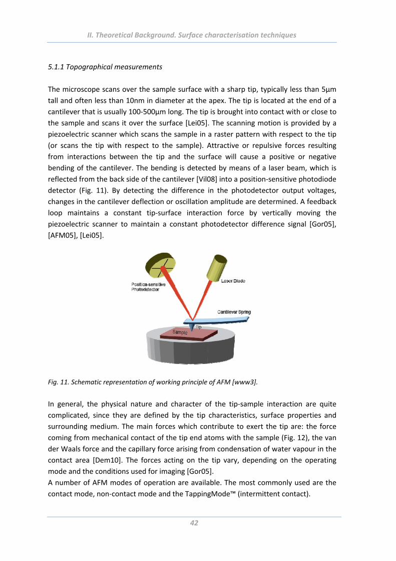
II. Theoretical Background. Surface characterisation techniques
42
5.1.1 Topographical measurements
The microscope scans over the sample surface with a sharp tip, typically less than 5µm
tall and often less than 10nm in diameter at the apex. The tip is located at the end of a
cantilever that is usually 100‐500µm long. The tip is brought into contact with or close to
the sample and scans it over the surface [Lei05]. The scanning motion is provided by a
piezoelectric scanner which scans the sample in a raster pattern with respect to the tip
(or scans the tip with respect to the sample). Attractive or repulsive forces resulting
from interactions between the tip and the surface will cause a positive or negative
bending of the cantilever. The bending is detected by means of a laser beam, which is
reflected from the back side of the cantilever [Vil08] into a position‐sensitive photodiode
detector (Fig. 11). By detecting the difference in the photodetector output voltages,
changes in the cantilever deflection or oscillation amplitude are determined. A feedback
loop maintains a constant tip‐surface interaction force by vertically moving the
piezoelectric scanner to maintain a constant photodetector difference signal [Gor05],
[AFM05], [Lei05].
Fig. 11. Schematic representation of working principle of AFM [www3].
In general, the physical nature and character of the tip‐sample interaction are quite
complicated, since they are defined by the tip characteristics, surface properties and
surrounding medium. The main forces which contribute to exert the tip are: the force
coming from mechanical contact of the tip end atoms with the sample (Fig. 12), the van
der Waals force and the capillary force arising from condensation of water vapour in the
contact area [Dem10]. The forces acting on the tip vary, depending on the operating
mode and the conditions used for imaging [Gor05].
A number of AFM modes of operation are available. The most commonly used are the
contact mode, non‐contact mode and the TappingMode™ (intermittent contact).
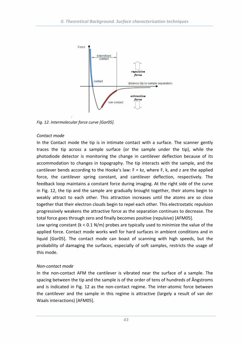
II. Theoretical Background. Surface characterisation techniques
43
.
Fig. 12. Intermolecular force curve [Gor05].
Contact mode
In the Contact mode the tip is in intimate contact with a surface. The scanner gently
traces the tip across a sample surface (or the sample under the tip), while the
photodiode detector is monitoring the change in cantilever deflection because of its
accommodation to changes in topography. The tip interacts with the sample, and the
cantilever bends according to the Hooke’s law: F = kz, where F, k, and z are the applied
force, the cantilever spring constant, and cantilever deflection, respectively. The
feedback loop maintains a constant force during imaging. At the right side of the curve
in Fig. 12, the tip and the sample are gradually brought together, their atoms begin to
weakly attract to each other. This attraction increases until the atoms are so close
together that their electron clouds begin to repel each other. This electrostatic repulsion
progressively weakens the attractive force as the separation continues to decrease. The
total force goes through zero and finally becomes positive (repulsive) [AFM05].
Low spring constant (k < 0.1 N/m) probes are typically used to minimize the value of the
applied force. Contact mode works well for hard surfaces in ambient conditions and in
liquid [Gor05]. The contact mode can boast of scanning with high speeds, but the
probability of damaging the surfaces, especially of soft samples, restricts the usage of
this mode.
Non‐contact mode
In the non‐contact AFM the cantilever is vibrated near the surface of a sample. The
spacing between the tip and the sample is of the order of tens of hundreds of Ångstroms
and is indicated in Fig. 12 as the non‐contact regime. The inter‐atomic force between
the cantilever and the sample in this regime is attractive (largely a result of van der
Waals interactions) [AFM05].
II. Theoretical Background. Surface characterisation techniques
44
In non‐contact mode, the system vibrates a stiff cantilever near its resonant frequency
(typically 100‐400 kHz) with amplitude of a few tens to hundreds of Ångstroms. The
system detects changes in the cantilever’s resonance frequency or vibration amplitude
and keeps it constant by moving the scanner up or down in response to changes. In this
way, the average tip‐sample distance is also kept constant and the Z feedback signal is
used to generate the data set [AFM05]. Low forces are exerted in the non‐contact mode,
it is especially important while scanning of fragile and soft surfaces. Disadvantages of
this mode are relative slower scan speed (to avoid contact with the fluid) and lower
lateral resolution because of the tip‐sample separation [Vil08].
TappingModeTM
TappingModeTM AFM, the most commonly used of all AFM modes, is a patented
technique (Veeco Instruments). During the scanning the cantilever oscillates slightly
above its resonant frequency, and it contacts (taps) the surface for a short period during
its oscillation cycle. By monitoring the changes in the cantilever’s oscillation amplitude
caused by changing of the sample surface, the topography images can be obtained.
TappingMode has become an important AFM technique, because it overcomes some of
the limitations of both contact and non‐contact modes. Firstly, the tapping mode
eliminates the lateral, shear forces. Since the contact time between the tip and the
sample is two orders shorter as compared to contact mode, the TappingMode is less
damaging. It is typically used for imaging topography of soft, fragile and adhesive
materials without damaging them.
Another major advantage of TappingMode is related to limitations that can arise due to
the thin layer of liquid that forms on most sample surfaces in an ambient imaging
environment. The amplitude of the cantilever in TappingMode is considerably higher
than in non‐contact mode and is usually in the range of 100 nm. It prevents the tip being
stuck in this liquid layer that often happens by scanning in the non‐contact mode.
In general, TappingMode is much more effective than non‐contact AFM, but especially
for imaging larger areas on the sample that may include greater variations in
topography. TappingMode can be performed in gases and non‐corrosive liquids
[AFM05]. Because of the high amplitude of oscillation, the tip propagates through
regions of attractive (van der Waals, electrostatic) and repulsive forces in a single
oscillation cycle (Fig. 12). The amplitude and the frequency of the cantilever decrease
while approaching the sample surface. Upon scanning, these parameters (and, hence,
the force gradient) are maintained constant at a set‐point level by the feedback loop
[Dem10], [Gor05].
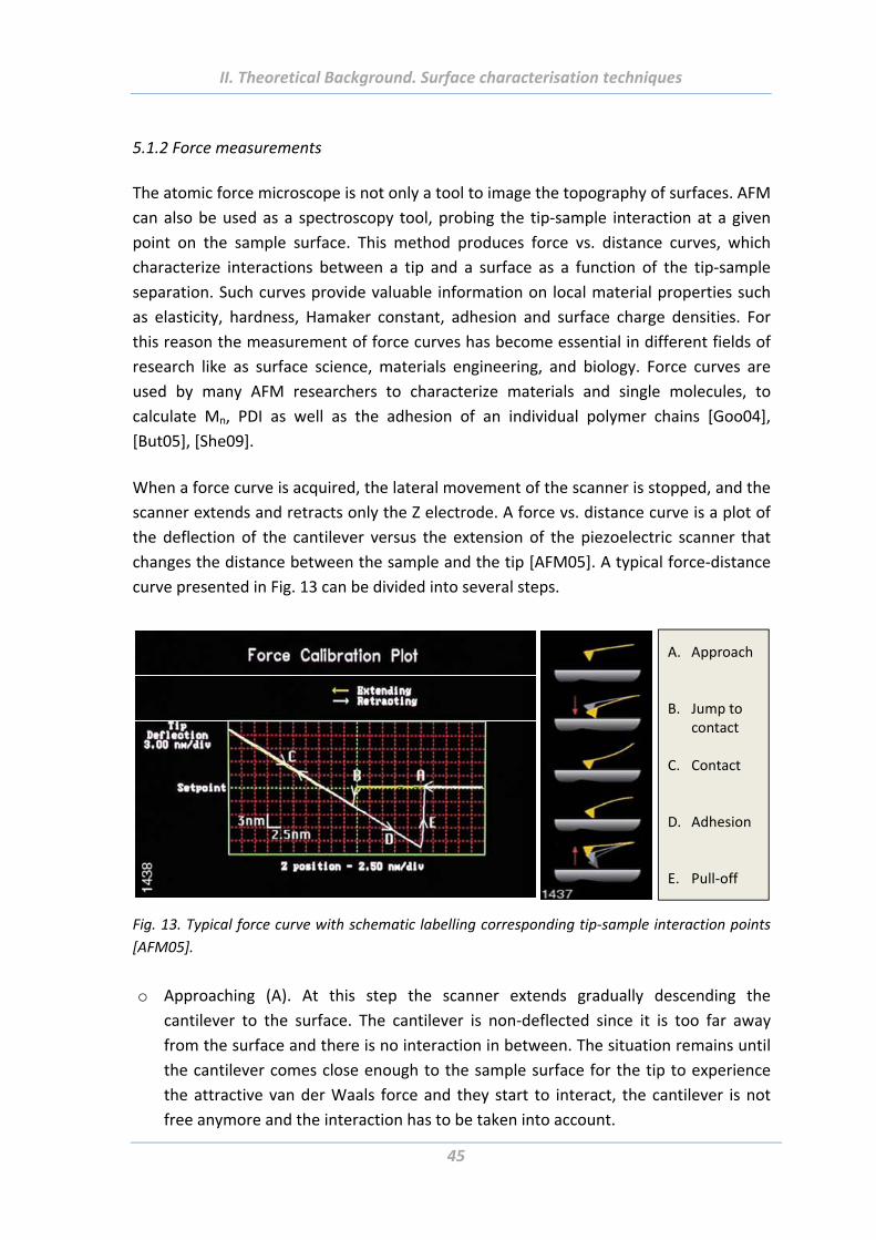
II. Theoretical Background. Surface characterisation techniques
45
5.1.2 Force measurements
The atomic force microscope is not only a tool to image the topography of surfaces. AFM
can also be used as a spectroscopy tool, probing the tip‐sample interaction at a given
point on the sample surface. This method produces force vs. distance curves, which
characterize interactions between a tip and a surface as a function of the tip‐sample
separation. Such curves provide valuable information on local material properties such
as elasticity, hardness, Hamaker constant, adhesion and surface charge densities. For
this reason the measurement of force curves has become essential in different fields of
research like as surface science, materials engineering, and biology. Force curves are
used by many AFM researchers to characterize materials and single molecules, to
calculate Mn, PDI as well as the adhesion of an individual polymer chains [Goo04],
[But05], [She09].
When a force curve is acquired, the lateral movement of the scanner is stopped, and the
scanner extends and retracts only the Z electrode. A force vs. distance curve is a plot of
the deflection of the cantilever versus the extension of the piezoelectric scanner that
changes the distance between the sample and the tip [AFM05]. A typical force‐distance
curve presented in Fig. 13 can be divided into several steps.
A. Approach
B. Jump tocontact
C. Contact
D. Adhesion
E. Pull‐off
Fig. 13. Typical force curve with schematic labelling corresponding tip‐sample interaction points
[AFM05].
o Approaching (A). At this step the scanner extends gradually descending the
cantilever to the surface. The cantilever is non‐deflected since it is too far away
from the surface and there is no interaction in between. The situation remains until
the cantilever comes close enough to the sample surface for the tip to experience
the attractive van der Waals force and they start to interact, the cantilever is not
free anymore and the interaction has to be taken into account.
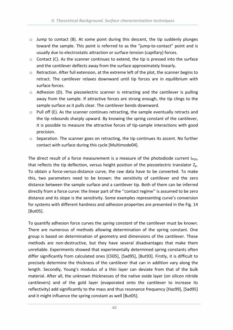
II. Theoretical Background. Surface characterisation techniques
46
o Jump to contact (B). At some point during this descent, the tip suddenly plunges
toward the sample. This point is referred to as the “jump‐to‐contact” point and is
usually due to electrostatic attraction or surface tension (capillary) forces.
o Contact (C). As the scanner continues to extend, the tip is pressed into the surface
and the cantilever deflects away from the surface approximately linearly.
o Retraction. After full extension, at the extreme left of the plot, the scanner begins to
retract. The cantilever relaxes downward until tip forces are in equilibrium with
surface forces.
o Adhesion (D). The piezoelectric scanner is retracting and the cantilever is pulling
away from the sample. If attractive forces are strong enough, the tip clings to the
sample surface as it pulls clear. The cantilever bends downward.
o Pull off (E). As the scanner continues retracting, the sample eventually retracts and
the tip rebounds sharply upward. By knowing the spring constant of the cantilever,
it is possible to measure the attractive forces of tip‐sample interactions with good
precision.
o Separation. The scanner goes on retracting, the tip continues its ascent. No further
contact with surface during this cycle [Multimode04].
The direct result of a force measurement is a measure of the photodiode current IPSD,
that reflects the tip deflection, versus height position of the piezoelectric translator Zp.
To obtain a force‐versus‐distance curve, the raw data have to be converted. To make
this, two parameters need to be known: the sensitivity of cantilever and the zero
distance between the sample surface and a cantilever tip. Both of them can be inferred
directly from a force curve: the linear part of the ‘‘contact regime’’ is assumed to be zero
distance and its slope is the sensitivity. Some examples representing curve’s conversion
for systems with different hardness and adhesion properties are presented in the Fig. 14
[But05].
To quantify adhesion force curves the spring constant of the cantilever must be known.
There are numerous of methods allowing determination of the spring constant. One
group is based on determination of geometry and dimensions of the cantilever. These
methods are non‐destructive, but they have several disadvantages that make them
unreliable. Experiments showed that experimentally determined spring constants often
differ significantly from calculated ones [Cli05], [Sad95], [But93]. Firstly, it is difficult to
precisely determine the thickness of the cantilever that can in addition vary along the
length. Secondly, Young’s modulus of a thin layer can deviate from that of the bulk
material. After all, the unknown thicknesses of the native oxide layer (on silicon nitride
cantilevers) and of the gold layer (evaporated onto the cantilever to increase its
reflectivity) add significantly to the mass and thus resonance frequency [Haz99], [Sad95]
and it might influence the spring constant as well [But05].
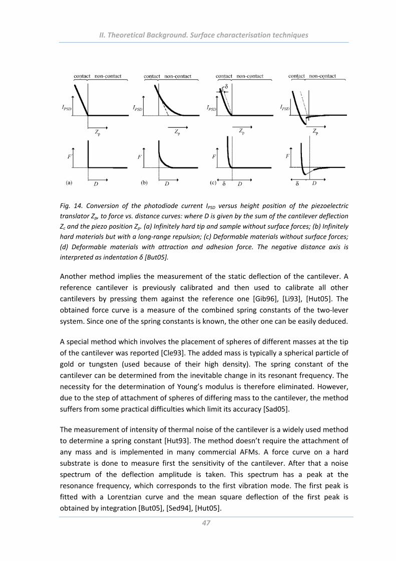
II. Theoretical Background. Surface characterisation techniques
47
Fig. 14. Conversion of the photodiode current IPSD versus height position of the piezoelectric
translator Zp, to force vs. distance curves: where D is given by the sum of the cantilever deflection
Zc and the piezo position Zp. (a) Infinitely hard tip and sample without surface forces; (b) Infinitely
hard materials but with a long‐range repulsion; (c) Deformable materials without surface forces;
(d) Deformable materials with attraction and adhesion force. The negative distance axis is
interpreted as indentation δ [But05].
Another method implies the measurement of the static deflection of the cantilever. A
reference cantilever is previously calibrated and then used to calibrate all other
cantilevers by pressing them against the reference one [Gib96], [Li93], [Hut05]. The
obtained force curve is a measure of the combined spring constants of the two‐lever
system. Since one of the spring constants is known, the other one can be easily deduced.
A special method which involves the placement of spheres of different masses at the tip
of the cantilever was reported [Cle93]. The added mass is typically a spherical particle of
gold or tungsten (used because of their high density). The spring constant of the
cantilever can be determined from the inevitable change in its resonant frequency. The
necessity for the determination of Young’s modulus is therefore eliminated. However,
due to the step of attachment of spheres of differing mass to the cantilever, the method
suffers from some practical difficulties which limit its accuracy [Sad05].
The measurement of intensity of thermal noise of the cantilever is a widely used method
to determine a spring constant [Hut93]. The method doesn’t require the attachment of
any mass and is implemented in many commercial AFMs. A force curve on a hard
substrate is done to measure first the sensitivity of the cantilever. After that a noise
spectrum of the deflection amplitude is taken. This spectrum has a peak at the
resonance frequency, which corresponds to the first vibration mode. The first peak is
fitted with a Lorentzian curve and the mean square deflection of the first peak is
obtained by integration [But05], [Sed94], [Hut05].
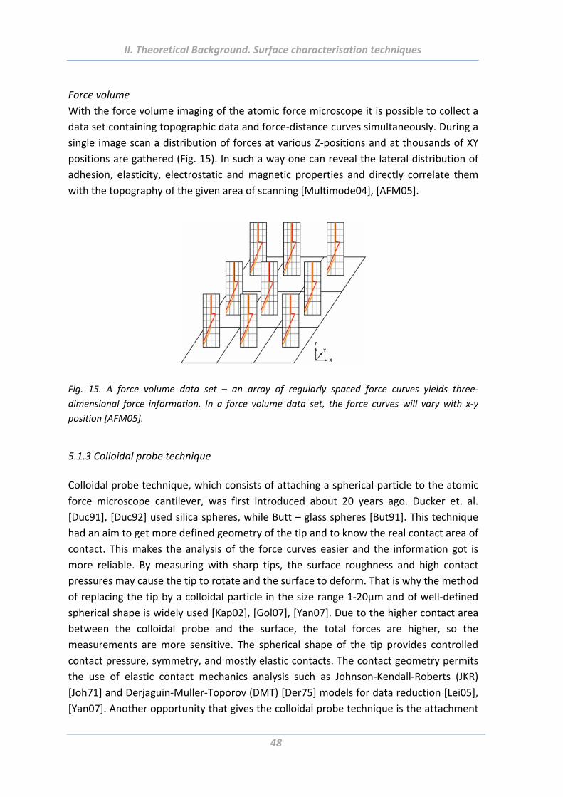
II. Theoretical Background. Surface characterisation techniques
48
Force volume
With the force volume imaging of the atomic force microscope it is possible to collect a
data set containing topographic data and force‐distance curves simultaneously. During a
single image scan a distribution of forces at various Z‐positions and at thousands of XY
positions are gathered (Fig. 15). In such a way one can reveal the lateral distribution of
adhesion, elasticity, electrostatic and magnetic properties and directly correlate them
with the topography of the given area of scanning [Multimode04], [AFM05].
Fig. 15. A force volume data set – an array of regularly spaced force curves yields three‐
dimensional force information. In a force volume data set, the force curves will vary with x‐y
position [AFM05].
5.1.3 Colloidal probe technique
Colloidal probe technique, which consists of attaching a spherical particle to the atomic
force microscope cantilever, was first introduced about 20 years ago. Ducker et. al.
[Duc91], [Duc92] used silica spheres, while Butt – glass spheres [But91]. This technique
had an aim to get more defined geometry of the tip and to know the real contact area of
contact. This makes the analysis of the force curves easier and the information got is
more reliable. By measuring with sharp tips, the surface roughness and high contact
pressures may cause the tip to rotate and the surface to deform. That is why the method
of replacing the tip by a colloidal particle in the size range 1‐20µm and of well‐defined
spherical shape is widely used [Kap02], [Gol07], [Yan07]. Due to the higher contact area
between the colloidal probe and the surface, the total forces are higher, so the
measurements are more sensitive. The spherical shape of the tip provides controlled
contact pressure, symmetry, and mostly elastic contacts. The contact geometry permits
the use of elastic contact mechanics analysis such as Johnson‐Kendall‐Roberts (JKR)
[Joh71] and Derjaguin‐Muller‐Toporov (DMT) [Der75] models for data reduction [Lei05],
[Yan07]. Another opportunity that gives the colloidal probe technique is the attachment
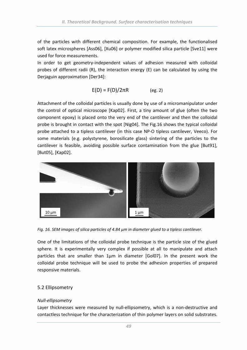
II. Theoretical Background. Surface characterisation techniques
49
of the particles with different chemical composition. For example, the functionalised
soft latex microspheres [Ass06], [Xu06] or polymer modified silica particle [Sve11] were
used for force measurements.
In order to get geometry‐independent values of adhesion measured with colloidal
probes of different radii (R), the interaction energy (E) can be calculated by using the
Derjaguin approximation [Der34]:
E(D) = F(D)/2πR (eg. 2)
Attachment of the colloidal particles is usually done by use of a micromanipulator under
the control of optical microscope [Kap02]. First, a tiny amount of glue (often the two
component epoxy) is placed onto the very end of the cantilever and then the colloidal
probe is brought in contact with the spot [Nig04]. The Fig.16 shows the typical colloidal
probe attached to a tipless cantilever (in this case NP‐O tipless cantilever, Veeco). For
some materials (e.g. polystyrene, borosilicate glass) sintering of the particles to the
cantilever is feasible, avoiding possible surface contamination from the glue [But91],
[But05], [Kap02].
10 µm 1 µm
Fig. 16. SEM images of silica particles of 4.84 µm in diameter glued to a tipless cantilever.
One of the limitations of the colloidal probe technique is the particle size of the glued
sphere. It is experimentally very complex if possible at all to manipulate and attach
particles that are smaller than 1µm in diameter [Gol07]. In the present work the
colloidal probe technique will be used to probe the adhesion properties of prepared
responsive materials.
5.2 Ellipsometry
Null‐ellipsometry
Layer thicknesses were measured by null‐ellipsometry, which is a non‐destructive and
contactless technique for the characterization of thin polymer layers on solid substrates.
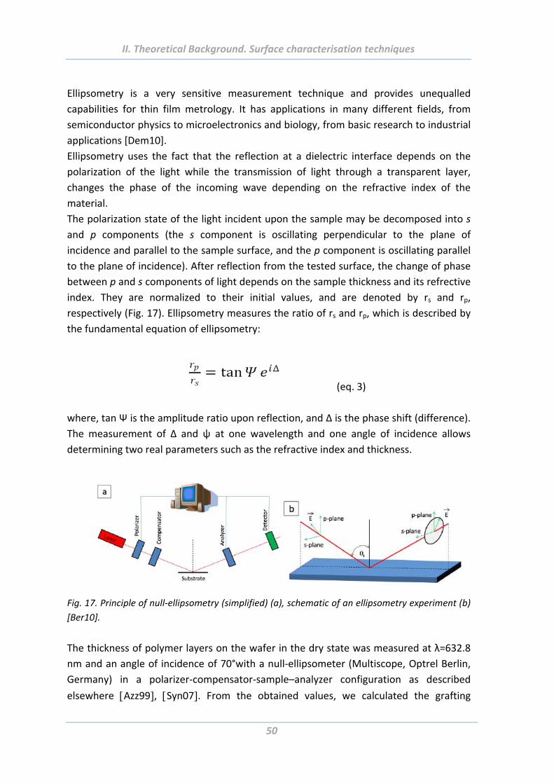
II. Theoretical Background. Surface characterisation techniques
50
Ellipsometry is a very sensitive measurement technique and provides unequalled
capabilities for thin film metrology. It has applications in many different fields, from
semiconductor physics to microelectronics and biology, from basic research to industrial
applications [Dem10].
Ellipsometry uses the fact that the reflection at a dielectric interface depends on the
polarization of the light while the transmission of light through a transparent layer,
changes the phase of the incoming wave depending on the refractive index of the
material.
The polarization state of the light incident upon the sample may be decomposed into s
and p components (the s component is oscillating perpendicular to the plane of
incidence and parallel to the sample surface, and the p component is oscillating parallel
to the plane of incidence). After reflection from the tested surface, the change of phase
between p and s components of light depends on the sample thickness and its refrective
index. They are normalized to their initial values, and are denoted by rs and rp,
respectively (Fig. 17). Ellipsometry measures the ratio of rs and rp, which is described by
the fundamental equation of ellipsometry:
(eq. 3)
where, tan Ψ is the amplitude ratio upon reflection, and Δ is the phase shift (difference).
The measurement of Δ and ψ at one wavelength and one angle of incidence allows
determining two real parameters such as the refractive index and thickness.
Fig. 17. Principle of null‐ellipsometry (simplified) (a), schematic of an ellipsometry experiment (b)
[Ber10].
The thickness of polymer layers on the wafer in the dry state was measured at λ=632.8
nm and an angle of incidence of 70°with a null‐ellipsometer (Multiscope, Optrel Berlin,
Germany) in a polarizer‐compensator‐sample–analyzer configuration as described
elsewhere Azz99, Syn07. From the obtained values, we calculated the grafting
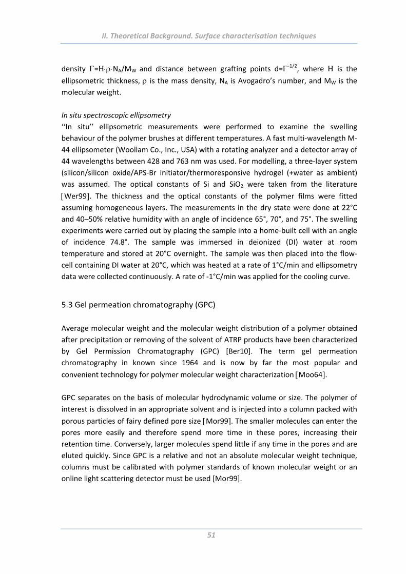
II. Theoretical Background. Surface characterisation techniques
51
density =NA/MW and distance between grafting points d=‐1/2, where is the ellipsometric thickness, is the mass density, NA is Avogadro’s number, and MW is the
molecular weight.
In situ spectroscopic ellipsometry
‘‘In situ’’ ellipsometric measurements were performed to examine the swelling
behaviour of the polymer brushes at different temperatures. A fast multi‐wavelength M‐
44 ellipsometer (Woollam Co., Inc., USA) with a rotating analyzer and a detector array of
44 wavelengths between 428 and 763 nm was used. For modelling, a three‐layer system
(silicon/silicon oxide/APS‐Br initiator/thermoresponsive hydrogel (+water as ambient)
was assumed. The optical constants of Si and SiO2 were taken from the literature
Wer99. The thickness and the optical constants of the polymer films were fitted
assuming homogeneous layers. The measurements in the dry state were done at 22°C
and 40–50% relative humidity with an angle of incidence 65°, 70°, and 75°. The swelling
experiments were carried out by placing the sample into a home‐built cell with an angle
of incidence 74.8°. The sample was immersed in deionized (DI) water at room
temperature and stored at 20°C overnight. The sample was then placed into the flow‐
cell containing DI water at 20°C, which was heated at a rate of 1°C/min and ellipsometry
data were collected continuously. A rate of ‐1°C/min was applied for the cooling curve.
5.3 Gel permeation chromatography (GPC)
Average molecular weight and the molecular weight distribution of a polymer obtained
after precipitation or removing of the solvent of ATRP products have been characterized
by Gel Permission Chromatography (GPC) [Ber10]. The term gel permeation
chromatography in known since 1964 and is now by far the most popular and
convenient technology for polymer molecular weight characterization Moo64.
GPC separates on the basis of molecular hydrodynamic volume or size. The polymer of
interest is dissolved in an appropriate solvent and is injected into a column packed with
porous particles of fairy defined pore size Mor99. The smaller molecules can enter the
pores more easily and therefore spend more time in these pores, increasing their
retention time. Conversely, larger molecules spend little if any time in the pores and are
eluted quickly. Since GPC is a relative and not an absolute molecular weight technique,
columns must be calibrated with polymer standards of known molecular weight or an
online light scattering detector must be used [Mor99].
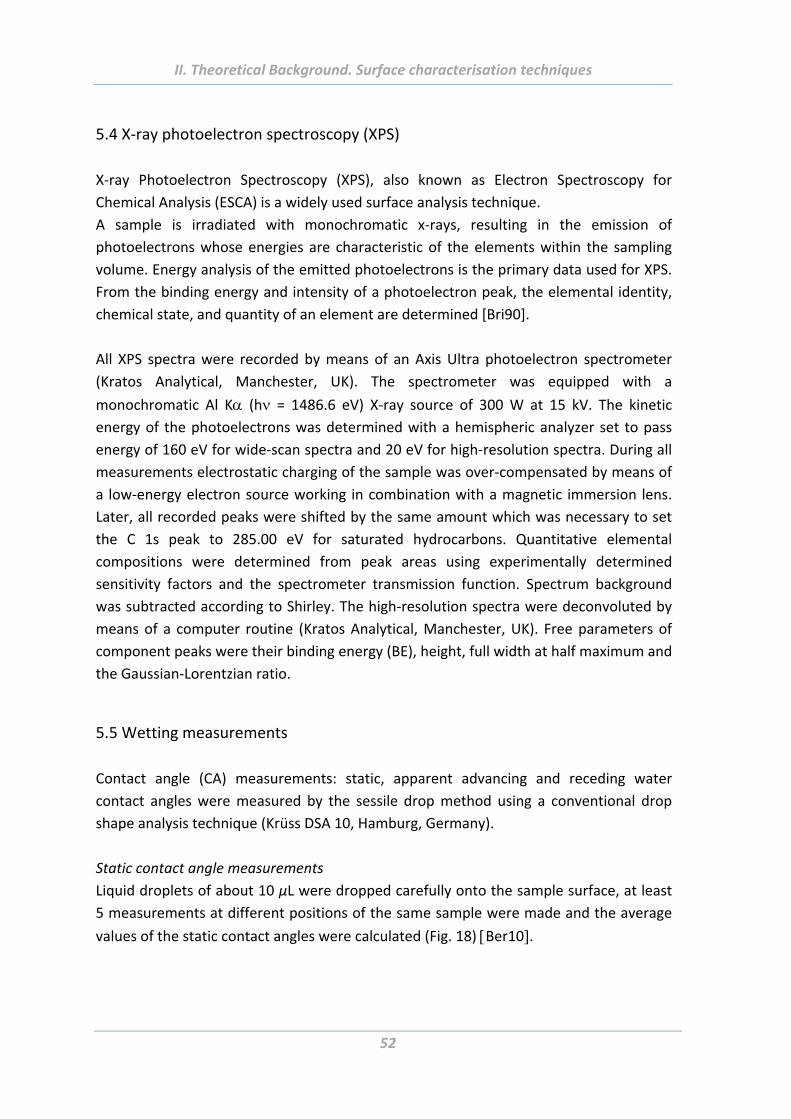
II. Theoretical Background. Surface characterisation techniques
52
5.4 X‐ray photoelectron spectroscopy (XPS)
X‐ray Photoelectron Spectroscopy (XPS), also known as Electron Spectroscopy for
Chemical Analysis (ESCA) is a widely used surface analysis technique.
A sample is irradiated with monochromatic x‐rays, resulting in the emission of
photoelectrons whose energies are characteristic of the elements within the sampling
volume. Energy analysis of the emitted photoelectrons is the primary data used for XPS.
From the binding energy and intensity of a photoelectron peak, the elemental identity,
chemical state, and quantity of an element are determined [Bri90].
All XPS spectra were recorded by means of an Axis Ultra photoelectron spectrometer
(Kratos Analytical, Manchester, UK). The spectrometer was equipped with a
monochromatic Al K (h = 1486.6 eV) X‐ray source of 300 W at 15 kV. The kinetic
energy of the photoelectrons was determined with a hemispheric analyzer set to pass
energy of 160 eV for wide‐scan spectra and 20 eV for high‐resolution spectra. During all
measurements electrostatic charging of the sample was over‐compensated by means of
a low‐energy electron source working in combination with a magnetic immersion lens.
Later, all recorded peaks were shifted by the same amount which was necessary to set
the C 1s peak to 285.00 eV for saturated hydrocarbons. Quantitative elemental
compositions were determined from peak areas using experimentally determined
sensitivity factors and the spectrometer transmission function. Spectrum background
was subtracted according to Shirley. The high‐resolution spectra were deconvoluted by
means of a computer routine (Kratos Analytical, Manchester, UK). Free parameters of
component peaks were their binding energy (BE), height, full width at half maximum and
the Gaussian‐Lorentzian ratio.
5.5 Wetting measurements
Contact angle (CA) measurements: static, apparent advancing and receding water
contact angles were measured by the sessile drop method using a conventional drop
shape analysis technique (Krüss DSA 10, Hamburg, Germany).
Static contact angle measurements
Liquid droplets of about 10 μL were dropped carefully onto the sample surface, at least
5 measurements at different positions of the same sample were made and the average
values of the static contact angles were calculated (Fig. 18) Ber10.
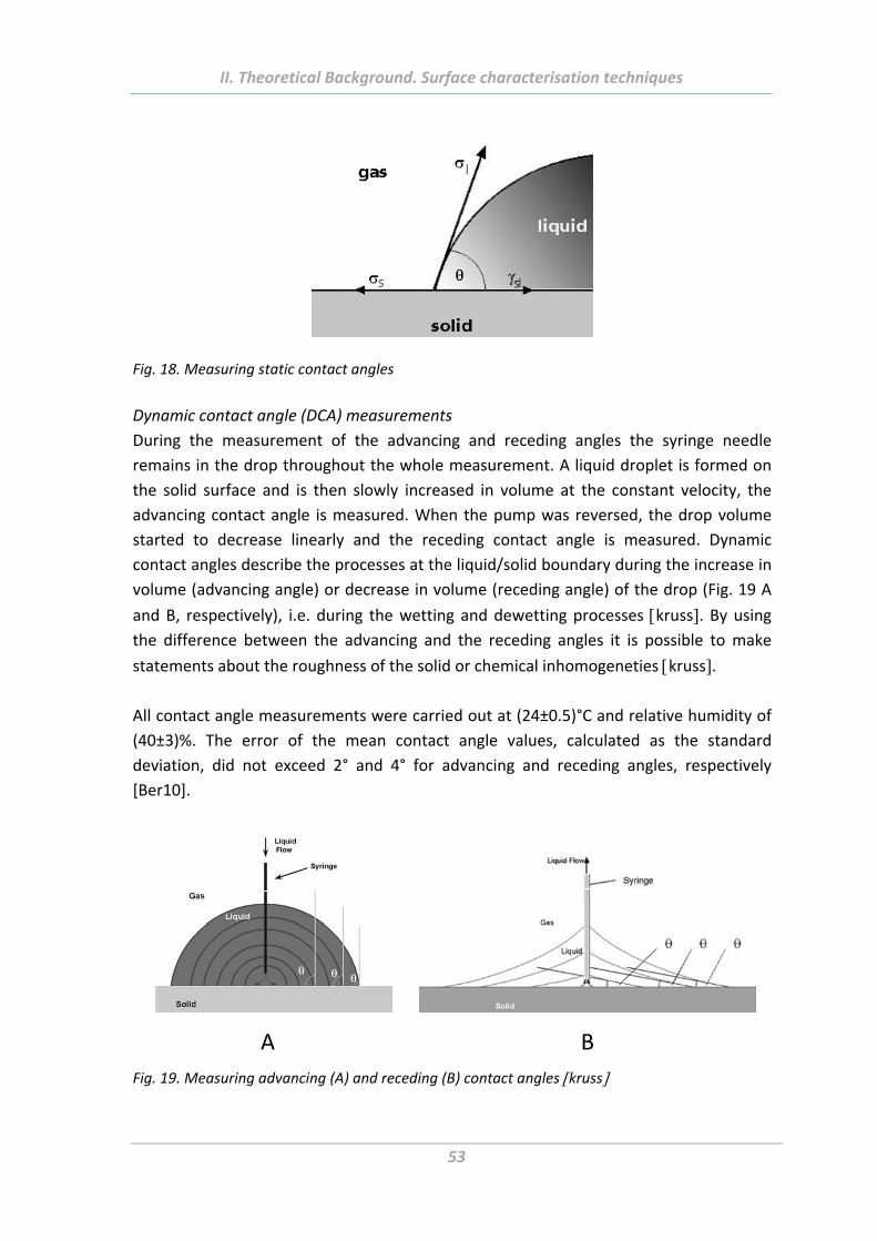
II. Theoretical Background. Surface characterisation techniques
53
Fig. 18. Measuring static contact angles
Dynamic contact angle (DCA) measurements
During the measurement of the advancing and receding angles the syringe needle
remains in the drop throughout the whole measurement. A liquid droplet is formed on
the solid surface and is then slowly increased in volume at the constant velocity, the
advancing contact angle is measured. When the pump was reversed, the drop volume
started to decrease linearly and the receding contact angle is measured. Dynamic
contact angles describe the processes at the liquid/solid boundary during the increase in
volume (advancing angle) or decrease in volume (receding angle) of the drop (Fig. 19 A
and B, respectively), i.e. during the wetting and dewetting processes kruss. By using the difference between the advancing and the receding angles it is possible to make
statements about the roughness of the solid or chemical inhomogeneties kruss.
All contact angle measurements were carried out at (24±0.5)°C and relative humidity of
(40±3)%. The error of the mean contact angle values, calculated as the standard
deviation, did not exceed 2° and 4° for advancing and receding angles, respectively
[Ber10].
A B
Fig. 19. Measuring advancing (A) and receding (B) contact angles kruss
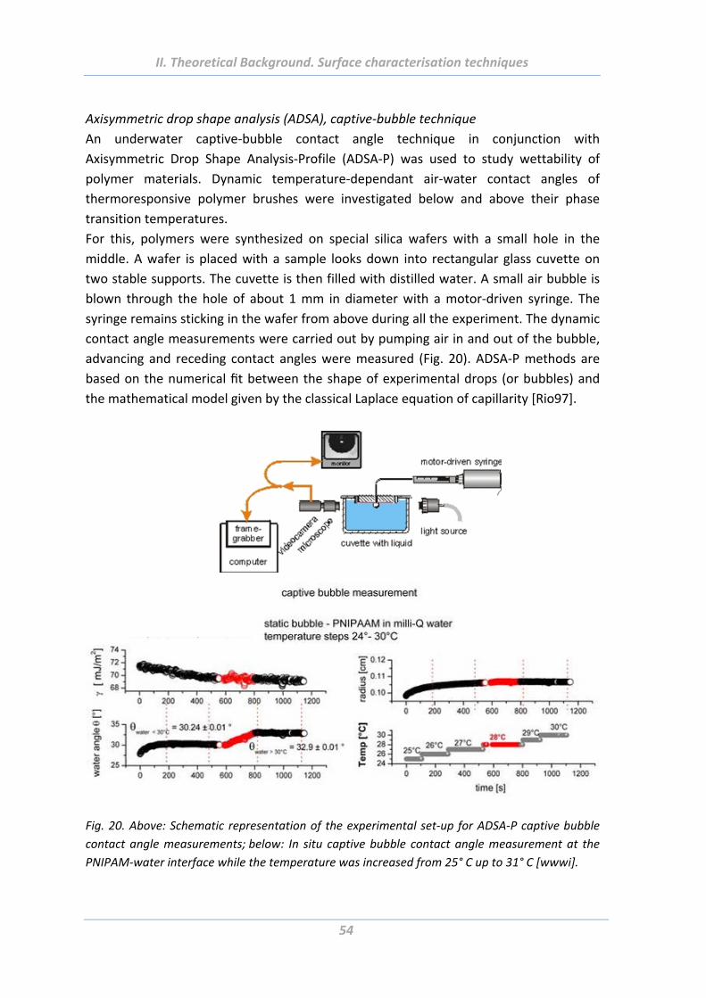
II. Theoretical Background. Surface characterisation techniques
54
Axisymmetric drop shape analysis (ADSA), captive‐bubble technique
An underwater captive‐bubble contact angle technique in conjunction with
Axisymmetric Drop Shape Analysis‐Profile (ADSA‐P) was used to study wettability of
polymer materials. Dynamic temperature‐dependant air‐water contact angles of
thermoresponsive polymer brushes were investigated below and above their phase
transition temperatures.
For this, polymers were synthesized on special silica wafers with a small hole in the
middle. A wafer is placed with a sample looks down into rectangular glass cuvette on
two stable supports. The cuvette is then filled with distilled water. A small air bubble is
blown through the hole of about 1 mm in diameter with a motor‐driven syringe. The
syringe remains sticking in the wafer from above during all the experiment. The dynamic
contact angle measurements were carried out by pumping air in and out of the bubble,
advancing and receding contact angles were measured (Fig. 20). ADSA‐P methods are
based on the numerical fit between the shape of experimental drops (or bubbles) and
the mathematical model given by the classical Laplace equation of capillarity [Rio97].
Fig. 20. Above: Schematic representation of the experimental set‐up for ADSA‐P captive bubble
contact angle measurements; below: In situ captive bubble contact angle measurement at the
PNIPAM‐water interface while the temperature was increased from 25° C up to 31° C [wwwi].
II. Theoretical Background. Surface characterisation techniques
55
5.6 Electrokinetic measurements
Zeta‐potential is the potential difference between the dispersion medium and the
stationary layer of fluid attached to the dispersed particle. The charge at the particle
surface influences the distribution of ions in the surrounding interfacial region. It results
in an increased concentration of counter ions close to the surface. Thus an electrical
double layer exists round each particle. The magnitude of the zeta‐potential shows if the
colloidal system stable or not. If all the particles in suspension have a large negative or
positive zeta‐potential then they will tend to repel each other and there is no tendency
to flocculate. However, if the particles have low zeta‐potential values then the system is
unstable and will be tending to flocculate.
The streaming potential measurements were carried out using the Electrokinetic
Analyzer (EKA) by Anton Paar GmbH, Graz, Austria in a special rectangular cell
(developed and constructed at the Leibniz Institute of Polymer Research, Dresden,
Germany) for small flat pieces. The measuring electrolyte (10‐3 M KCI) was circulated
though this channel. Details of the measuring technique are reported elsewhere Bel02, Bel07, Smo21. In this work in addition to the common zeta‐potential measurements,
electrokinetic behaviour of thermoresponsive polymer brushes upon heating‐cooling
cycles was investigated. Such the switch between swelled and collapsed states of the
brushes was confirmed.
5.7 Dynamic light scattering (DLS)
Dynamic light scattering (DLS) is one of the most popular technique used to determine
the size distribution profile of small particles in suspension or polymers in solution. With
this method particle sizes within a range from nm up to several μm can be determined
[Gor05]. A monochromatic light beam, such as a laser, shines onto a solution with
spherical particles. Due to the Brownian motion of the particles, a Doppler Shift occurs
that changes the wavelength of the incoming light. This change is related to the size of
the particle sartor. A Zetasizer Nano ZS by Malvern Instruments/UK was used for determination of particle
size. The device is equipped with a 633 nm laser and with a non‐invasive backscatter
(NIBS) technology for increasing particle size sensitivity [Ber10].
5.8 Scanning electron microscope (SEM)
SEM is a type of electron microscope that is able to provide images of three‐dimensional
objects with resolution less than 1 nm. The principal of work is based on the collection of
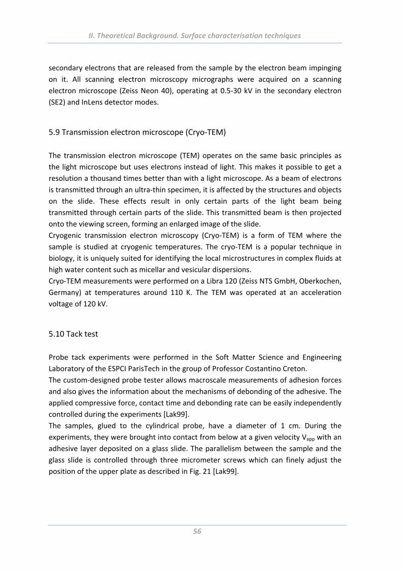
II. Theoretical Background. Surface characterisation techniques
56
secondary electrons that are released from the sample by the electron beam impinging
on it. All scanning electron microscopy micrographs were acquired on a scanning
electron microscope (Zeiss Neon 40), operating at 0.5‐30 kV in the secondary electron
(SE2) and InLens detector modes.
5.9 Transmission electron microscope (Cryo‐TEM)
The transmission electron microscope (TEM) operates on the same basic principles as
the light microscope but uses electrons instead of light. This makes it possible to get a
resolution a thousand times better than with a light microscope. As a beam of electrons
is transmitted through an ultra‐thin specimen, it is affected by the structures and objects
on the slide. These effects result in only certain parts of the light beam being
transmitted through certain parts of the slide. This transmitted beam is then projected
onto the viewing screen, forming an enlarged image of the slide.
Cryogenic transmission electron microscopy (Cryo‐TEM) is a form of TEM where the
sample is studied at cryogenic temperatures. The cryo‐TEM is a popular technique in
biology, it is uniquely suited for identifying the local microstructures in complex fluids at
high water content such as micellar and vesicular dispersions.
Cryo‐TEM measurements were performed on a Libra 120 (Zeiss NTS GmbH, Oberkochen,
Germany) at temperatures around 110 K. The TEM was operated at an acceleration
voltage of 120 kV.
5.10 Tack test
Probe tack experiments were performed in the Soft Matter Science and Engineering
Laboratory of the ESPCI ParisTech in the group of Professor Costantino Creton.
The custom‐designed probe tester allows macroscale measurements of adhesion forces
and also gives the information about the mechanisms of debonding of the adhesive. The
applied compressive force, contact time and debonding rate can be easily independently
controlled during the experiments [Lak99].
The samples, glued to the cylindrical probe, have a diameter of 1 cm. During the
experiments, they were brought into contact from below at a given velocity Vapp with an
adhesive layer deposited on a glass slide. The parallelism between the sample and the
glass slide is controlled through three micrometer screws which can finely adjust the
position of the upper plate as described in Fig. 21 [Lak99].
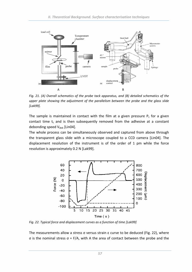
II. Theoretical Background. Surface characterisation techniques
57
A B
Fig. 21. (A) Overall schematics of the probe tack apparatus, and (B) detailed schematics of the
upper plate showing the adjustment of the parallelism between the probe and the glass slide
[Lak99].
The sample is maintained in contact with the film at a given pressure Pc for a given
contact time tc and is then subsequently removed from the adhesive at a constant
debonding speed Vdeb [Lin04].
The whole process can be simultaneously observed and captured from above through
the transparent glass slide with a microscope coupled to a CCD camera [Lin04]. The
displacement resolution of the instrument is of the order of 1 pm while the force
resolution is approximately 0.2 N [Lak99].
Fig. 22. Typical force and displacement curves as a function of time [Lak99]
The measurements allow a stress σ versus strain ε curve to be deduced (Fig. 22), where
σ is the nominal stress σ = F/A, with A the area of contact between the probe and the
II. Theoretical Background. Surface characterisation techniques
58
adhesive during the compressive stage, and ε = (h ‐ h0)/h0, where h is defined as the
time dependent thickness of the adhesive layer and h0 as the initial thickness [Lin04].
The shape of the stress‐strain curve obtained during the detachment of the sample from
the adhesive film can be used to characterize the adhesive performance of the material
tested and depends on the rheological properties of the adhesive layer and on the
interfacial interactions between the adhesive and the sample. The general features of a
stress‐strain curve obtained in a test will be characterized typically with three
parameters: a maximum stress, σmax, a maximum extension, εmax, and a work of
separation, W, defined as the integral under the stress‐strain curve [Cre02].
The debonding process can be divided into different stages. Images with the
corresponding stages of force‐displacement curve are shown in Fig. 23:
(1) Homogeneous deformation of the film in tension. No cavities are optically visible;
(2) Nucleation of the cavities at the interface, the cavities appear where surface defect
was initially present. If the surface of the sample or of the films has some degree of
roughness, pockets of air can remain trapped during the compression stage and act as
germs for cavities during the traction stage [Ret05]. This mechanism occurs near the
maximum in the measured nominal stress;
(3) Further two different mechanisms can be observed: either more and more cavities
progressively nucleate, eventually filling the space previously occupied by the adhesive
film (the structure resembles foam), or the cavities continue growing laterally and form
fibrillar structures [Lin04], [Cre03];
During the debonding on non‐adhesive surfaces large interfacial cracks which propagate
quickly from the boarder usually take place, whereas on more adherent surfaces
multiple cavities in the bulk of the adhesive layer have been observed which grow slowly
and lead to a fibrillar structure [Josse]. Video captures taken during the force relaxation
process can reveal whether cavitation or fibrillation takes place;
(4) Final stage of debonding: separation of the two surfaces either by failure of the fibrils
(cohesive failure, i.e. some adhesive remains on both surfaces) or by detachment of the
foot of the fibrils from the surface (adhesive failure, i.e. there is no adhesive left on the
probe surface) [Ret05], [Lin04], [Cre02], [Cre01], [Ret08].
Cavitation takes place at the beginning of the debonding process, while the stress
increases. Growth of the cavities leads to a decrease of the nominal stress until the
fibrillation stage is reached, leading to a plateau value of the stress. Finally, the
detachment of the fibrils occurs and complete debonding of the adhesive layer takes
place [Lin04].

II. Theoretical Background. Surface characterisation techniques
59
(1)
(2)
(3)
(4)
Fig. 23. Schematic of the deformation mechanisms taking place during a probe tack test and
corresponding images of the stages of debonding. The images are taken from [Lak98], [Cre02].

III. Results and Discussions. Thermoresponsive polymer brushes
61
III. Results and Discussions
1. Thermoresponsive polymer brushes
1.1 Abstract
In this Chapter it is reported on design, investigation and comparison of the adhesive
properties of poly‐(N‐isopropylacrylamide) and biocompatible polyethylene glycol‐based
thermoresponsive brushes. The brushes were synthesised on planar silicon wafers and
silica particles via the surface‐initiated atom transfer radical polymerisation. Switching of
swelling, surface charge and surface morphology were investigated using spectroscopic
ellipsometry, zeta‐potential and atomic force microscope measurements, respectively.
Adhesion properties were studied in situ in aqueous solutions at different temperatures
using three kinds of AFM probes with well‐defined tips geometries and radii.
1.2 Introduction
Stimuli‐responsive systems found in nature evoke considerable interest of scientific
community inspiring fabrication of artificial materials with similar properties [Aut00],
[Lee07], [Xia08], [Yos08]. There are a lot of attempts for mimicking natural systems
because of a great demand for “smartness” in adhesive materials for various fields of
application, like as tissue engineering, wound dressings, sensors, climbing robots,
adhesive foils etc. Polymers able to switch or adapt their adhesion properties as an
answer to external stimuli or change of environmental conditions such as temperature,
pH, light and others are already widely used as a basis for such responsive materials
[Hub03], [Gra04], [Lee10], [Nan10], [Liu12]. Among the polymers demonstrating
thermoresponsive behaviour in aqueous environment, there are polyacrylamides,
polyvinylcaprolactone, polyethyleneglycols, and polypeptides. Such thermoresponsive
polymers possess low critical solution temperature (LCST) that is a certain temperature
below which the polymers are water‐soluble and hydrophilic, but water‐insoluble and
hydrophobic above this temperature. Adhesive properties of thermoresponsive surfaces
play a keynote role for biotechnological applications. In fact, it was found that cells
readily adhere to the thermoresponsive substrates at elevated temperatures when the
polymer is hydrophobic and do not adhere or are released at lower temperatures when
the polymer is swollen. Therefore, understanding and control of adhesion properties of
thermoresponsive surfaces is very important for proper attachment/detachment of
cells.
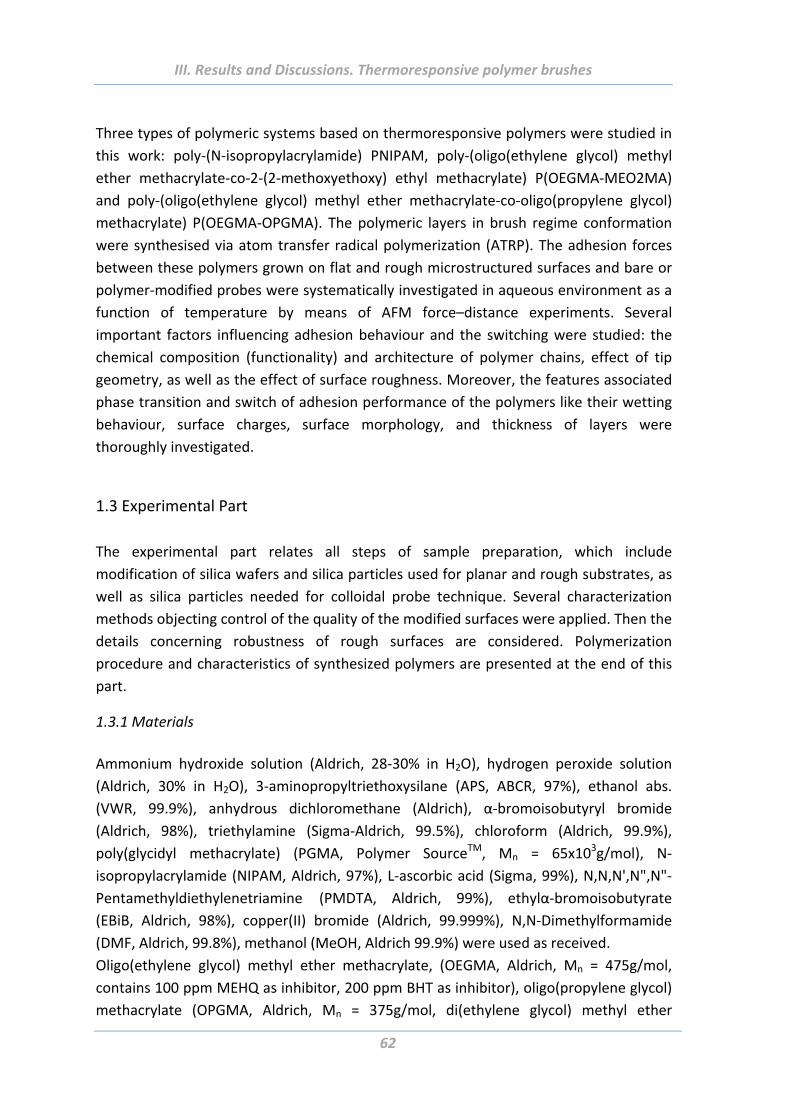
III. Results and Discussions. Thermoresponsive polymer brushes
62
Three types of polymeric systems based on thermoresponsive polymers were studied in
this work: poly‐(N‐isopropylacrylamide) PNIPAM, poly‐(oligo(ethylene glycol) methyl
ether methacrylate‐co‐2‐(2‐methoxyethoxy) ethyl methacrylate) P(OEGMA‐MEO2MA)
and poly‐(oligo(ethylene glycol) methyl ether methacrylate‐co‐oligo(propylene glycol)
methacrylate) P(OEGMA‐OPGMA). The polymeric layers in brush regime conformation
were synthesised via atom transfer radical polymerization (ATRP). The adhesion forces
between these polymers grown on flat and rough microstructured surfaces and bare or
polymer‐modified probes were systematically investigated in aqueous environment as a
function of temperature by means of AFM force–distance experiments. Several
important factors influencing adhesion behaviour and the switching were studied: the
chemical composition (functionality) and architecture of polymer chains, effect of tip
geometry, as well as the effect of surface roughness. Moreover, the features associated
phase transition and switch of adhesion performance of the polymers like their wetting
behaviour, surface charges, surface morphology, and thickness of layers were
thoroughly investigated.
1.3 Experimental Part
The experimental part relates all steps of sample preparation, which include
modification of silica wafers and silica particles used for planar and rough substrates, as
well as silica particles needed for colloidal probe technique. Several characterization
methods objecting control of the quality of the modified surfaces were applied. Then the
details concerning robustness of rough surfaces are considered. Polymerization
procedure and characteristics of synthesized polymers are presented at the end of this
part.
1.3.1 Materials
Ammonium hydroxide solution (Aldrich, 28‐30% in H2O), hydrogen peroxide solution
(Aldrich, 30% in H2O), 3‐aminopropyltriethoxysilane (APS, ABCR, 97%), ethanol abs.
(VWR, 99.9%), anhydrous dichloromethane (Aldrich), α‐bromoisobutyryl bromide
(Aldrich, 98%), triethylamine (Sigma‐Aldrich, 99.5%), chloroform (Aldrich, 99.9%),
poly(glycidyl methacrylate) (PGMA, Polymer SourceTM, Mn = 65x103g/mol), N‐
isopropylacrylamide (NIPAM, Aldrich, 97%), L‐ascorbic acid (Sigma, 99%), N,N,N',N",N"‐
Pentamethyldiethylenetriamine (PMDTA, Aldrich, 99%), ethylα‐bromoisobutyrate
(EBiB, Aldrich, 98%), copper(II) bromide (Aldrich, 99.999%), N,N‐Dimethylformamide
(DMF, Aldrich, 99.8%), methanol (MeOH, Aldrich 99.9%) were used as received.
Oligo(ethylene glycol) methyl ether methacrylate, (OEGMA, Aldrich, Mn = 475g/mol,
contains 100 ppm MEHQ as inhibitor, 200 ppm BHT as inhibitor), oligo(propylene glycol)
methacrylate (OPGMA, Aldrich, Mn = 375g/mol, di(ethylene glycol) methyl ether
III. Results and Discussions. Thermoresponsive polymer brushes
63
methacrylate (or 2‐(2‐methoxyethoxy) ethyl methacrylate, MEO2MA, Aldrich) were
distilled under nitrogen steam prior to the polymerization.
1.3.2 Modification of planar substrates
Highly polished single‐crystal silicon wafers of {100} orientation (Semiconductor
Processing Co.) were used as planar substrates. Several steps of wafers modification
were carried out upon the polymerization procedure. First, wafers were cleaned in
dichloromethane in ultrasonic bath during 30 minutes. Then after the removal of
dichloromethane, the wafers were placed in a hot solution (70°C) of NH4OH (ammonium
hydroxyde), H2O2 (hydrogen peroxide) and MilliQ water with ratio 1:1:1. After an hour
the wafers were rinsed several times with MilliQ water and dryed with nitrogen flux.
This treatment results in the formation of a thin silicon dioxide layer (about 1.3 nm). The
thickness of this as well as all other layers after each step of modification was controlled
via null‐ellipsometry measurement.
The silicon surface was next modified with 3‐aminopropyltriethoxysilane (APS). A thin
layer of APS (th = 0.6 nm) was adsorbed at room temperature on top of the wafers from
2 wt% ethanol solution.
Then the bromide initiator (BrInit) was immobilized on the surfaces by placing the
wafers into solution of anhydrous dichloromethane (100 ml), triethylamine (1ml) and α‐
bromoisobutyryl bromide (0.5 ml) for 2 hours at room temperature. Afterwards, the
wafers were rinsed several times with dichloromethane, ethanol and MilliQ water and
dried with nitrogen flux. The thickness of the APS+BrInit layer was measured to be 0.9
nm.
2 3 4 5 6 7 8 9 10
-80
-60
-40
-20
0
20
40
60 SiO2 native
SiO2/APS
SiO2/APS/BrIn
pH (10-3 M KCI)
App
are
nt z
eta
po
ten
tial,
mV
Fig. 24. Zeta potential measurements after steps of SiO2 native layer activization, silanization and
immobilization of bromide initiator.
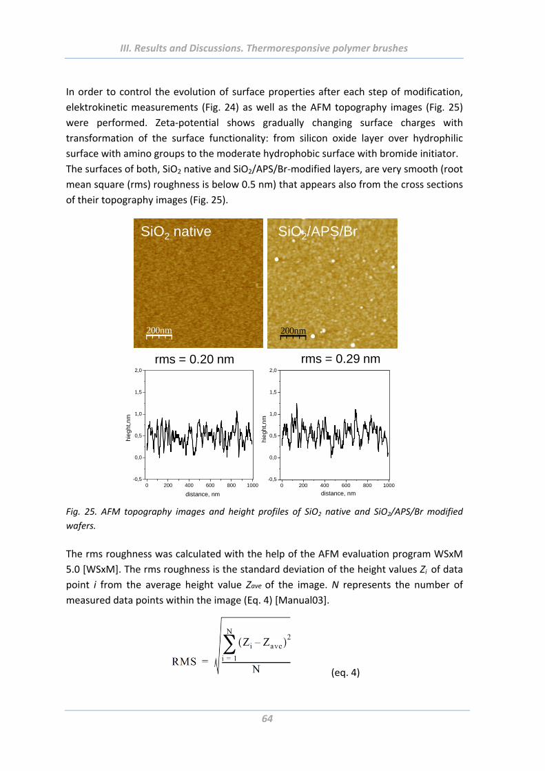
III. Results and Discussions. Thermoresponsive polymer brushes
64
In order to control the evolution of surface properties after each step of modification,
elektrokinetic measurements (Fig. 24) as well as the AFM topography images (Fig. 25)
were performed. Zeta‐potential shows gradually changing surface charges with
transformation of the surface functionality: from silicon oxide layer over hydrophilic
surface with amino groups to the moderate hydrophobic surface with bromide initiator.
The surfaces of both, SiO2 native and SiO2/APS/Br‐modified layers, are very smooth (root
mean square (rms) roughness is below 0.5 nm) that appears also from the cross sections
of their topography images (Fig. 25).
0 200 400 600 800 1000-0,5
0,0
0,5
1,0
1,5
2,0
hie
ght,
nm
distance, nm
rms = 0.20 nm rms = 0.29 nm
0 200 400 600 800 1000-0,5
0,0
0,5
1,0
1,5
2,0
hieg
ht,n
m
distance, nm
200nm
SiO2 native
200nm
SiO2/APS/Br
Fig. 25. AFM topography images and height profiles of SiO2 native and SiO2/APS/Br modified
wafers.
The rms roughness was calculated with the help of the AFM evaluation program WSxM
5.0 [WSxM]. The rms roughness is the standard deviation of the height values Zi of data
point i from the average height value Zave of the image. N represents the number of
measured data points within the image (Eq. 4) [Manual03].
(eq. 4)
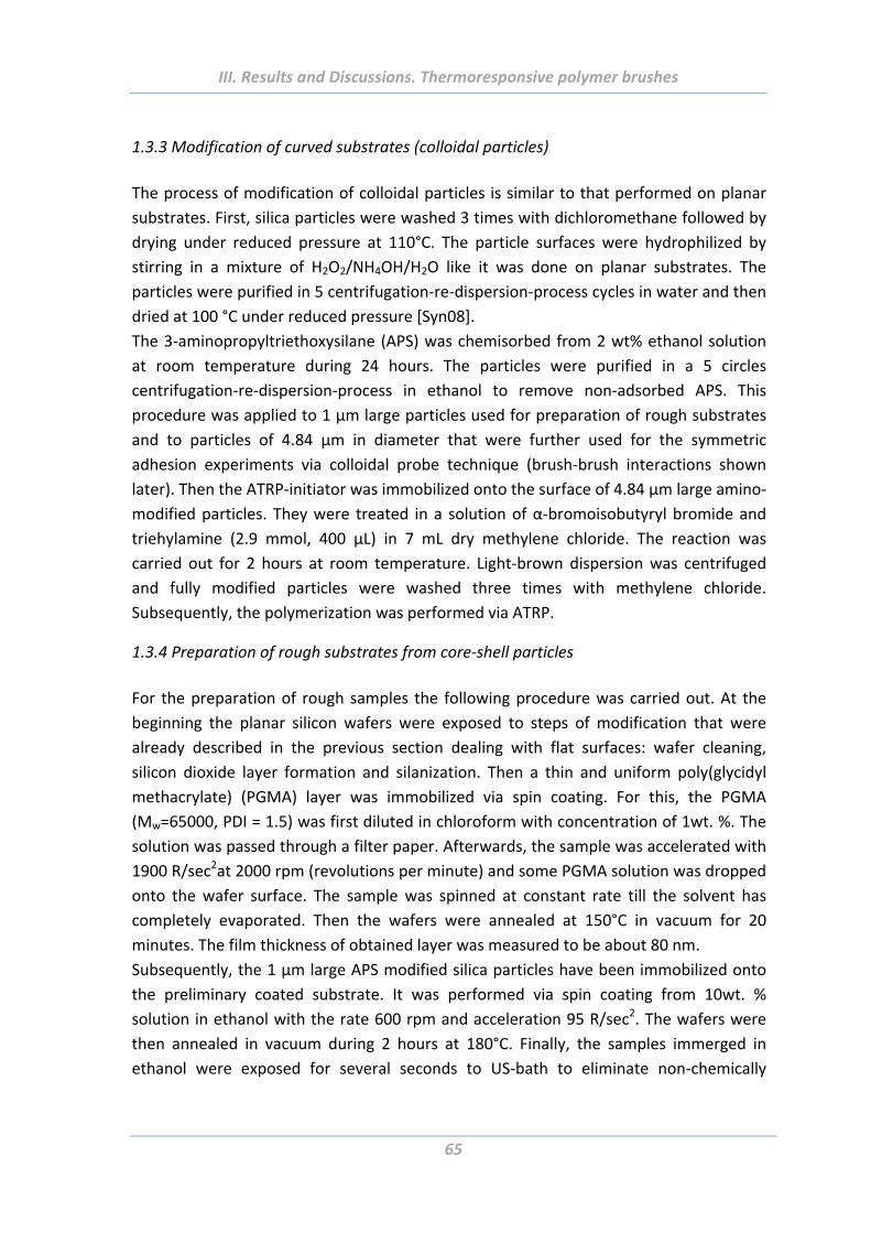
III. Results and Discussions. Thermoresponsive polymer brushes
65
1.3.3 Modification of curved substrates (colloidal particles)
The process of modification of colloidal particles is similar to that performed on planar
substrates. First, silica particles were washed 3 times with dichloromethane followed by
drying under reduced pressure at 110°C. The particle surfaces were hydrophilized by
stirring in a mixture of H2O2/NH4OH/H2O like it was done on planar substrates. The
particles were purified in 5 centrifugation‐re‐dispersion‐process cycles in water and then
dried at 100 °C under reduced pressure [Syn08].
The 3‐aminopropyltriethoxysilane (APS) was chemisorbed from 2 wt% ethanol solution
at room temperature during 24 hours. The particles were purified in a 5 circles
centrifugation‐re‐dispersion‐process in ethanol to remove non‐adsorbed APS. This
procedure was applied to 1 µm large particles used for preparation of rough substrates
and to particles of 4.84 µm in diameter that were further used for the symmetric
adhesion experiments via colloidal probe technique (brush‐brush interactions shown
later). Then the ATRP‐initiator was immobilized onto the surface of 4.84 µm large amino‐
modified particles. They were treated in a solution of α‐bromoisobutyryl bromide and
triehylamine (2.9 mmol, 400 μL) in 7 mL dry methylene chloride. The reaction was
carried out for 2 hours at room temperature. Light‐brown dispersion was centrifuged
and fully modified particles were washed three times with methylene chloride.
Subsequently, the polymerization was performed via ATRP.
1.3.4 Preparation of rough substrates from core‐shell particles
For the preparation of rough samples the following procedure was carried out. At the
beginning the planar silicon wafers were exposed to steps of modification that were
already described in the previous section dealing with flat surfaces: wafer cleaning,
silicon dioxide layer formation and silanization. Then a thin and uniform poly(glycidyl
methacrylate) (PGMA) layer was immobilized via spin coating. For this, the PGMA
(Mw=65000, PDI = 1.5) was first diluted in chloroform with concentration of 1wt. %. The
solution was passed through a filter paper. Afterwards, the sample was accelerated with
1900 R/sec2at 2000 rpm (revolutions per minute) and some PGMA solution was dropped
onto the wafer surface. The sample was spinned at constant rate till the solvent has
completely evaporated. Then the wafers were annealed at 150°C in vacuum for 20
minutes. The film thickness of obtained layer was measured to be about 80 nm.
Subsequently, the 1 µm large APS modified silica particles have been immobilized onto
the preliminary coated substrate. It was performed via spin coating from 10wt. %
solution in ethanol with the rate 600 rpm and acceleration 95 R/sec2. The wafers were
then annealed in vacuum during 2 hours at 180°C. Finally, the samples immerged in
ethanol were exposed for several seconds to US‐bath to eliminate non‐chemically
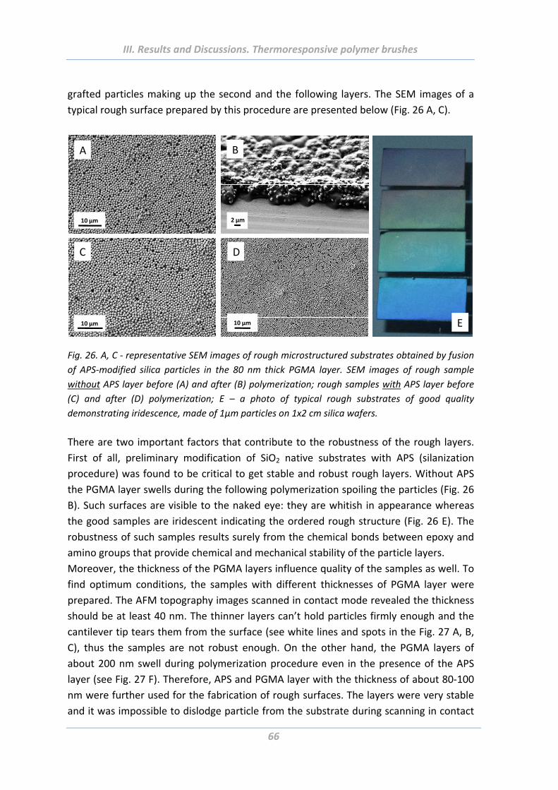
III. Results and Discussions. Thermoresponsive polymer brushes
66
grafted particles making up the second and the following layers. The SEM images of a
typical rough surface prepared by this procedure are presented below (Fig. 26 A, C).
10 µm
A B
DC
10 µm 10 µm
2 µm
E
Fig. 26. A, C ‐ representative SEM images of rough microstructured substrates obtained by fusion
of APS‐modified silica particles in the 80 nm thick PGMA layer. SEM images of rough sample
without APS layer before (A) and after (B) polymerization; rough samples with APS layer before
(C) and after (D) polymerization; E – a photo of typical rough substrates of good quality
demonstrating iridescence, made of 1µm particles on 1x2 cm silica wafers.
There are two important factors that contribute to the robustness of the rough layers.
First of all, preliminary modification of SiO2 native substrates with APS (silanization
procedure) was found to be critical to get stable and robust rough layers. Without APS
the PGMA layer swells during the following polymerization spoiling the particles (Fig. 26
B). Such surfaces are visible to the naked eye: they are whitish in appearance whereas
the good samples are iridescent indicating the ordered rough structure (Fig. 26 E). The
robustness of such samples results surely from the chemical bonds between epoxy and
amino groups that provide chemical and mechanical stability of the particle layers.
Moreover, the thickness of the PGMA layers influence quality of the samples as well. To
find optimum conditions, the samples with different thicknesses of PGMA layer were
prepared. The AFM topography images scanned in contact mode revealed the thickness
should be at least 40 nm. The thinner layers can’t hold particles firmly enough and the
cantilever tip tears them from the surface (see white lines and spots in the Fig. 27 A, B,
C), thus the samples are not robust enough. On the other hand, the PGMA layers of
about 200 nm swell during polymerization procedure even in the presence of the APS
layer (see Fig. 27 F). Therefore, APS and PGMA layer with the thickness of about 80‐100
nm were further used for the fabrication of rough surfaces. The layers were very stable
and it was impossible to dislodge particle from the substrate during scanning in contact
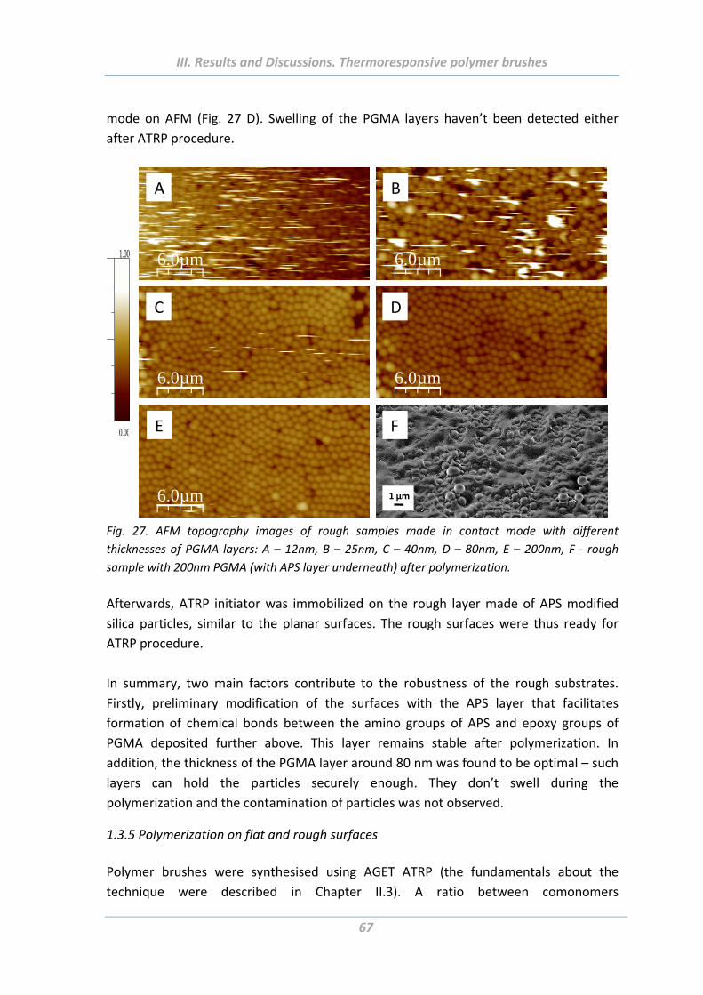
III. Results and Discussions. Thermoresponsive polymer brushes
67
mode on AFM (Fig. 27 D). Swelling of the PGMA layers haven’t been detected either
after ATRP procedure.
1.00
0.00
6.0µm
A
6.0µm
B
6.0µm
C
6.0µm
D
6.0µm
E F
1 µm
Fig. 27. AFM topography images of rough samples made in contact mode with different
thicknesses of PGMA layers: A – 12nm, B – 25nm, C – 40nm, D – 80nm, E – 200nm, F ‐ rough
sample with 200nm PGMA (with APS layer underneath) after polymerization.
Afterwards, ATRP initiator was immobilized on the rough layer made of APS modified
silica particles, similar to the planar surfaces. The rough surfaces were thus ready for
ATRP procedure.
In summary, two main factors contribute to the robustness of the rough substrates.
Firstly, preliminary modification of the surfaces with the APS layer that facilitates
formation of chemical bonds between the amino groups of APS and epoxy groups of
PGMA deposited further above. This layer remains stable after polymerization. In
addition, the thickness of the PGMA layer around 80 nm was found to be optimal – such
layers can hold the particles securely enough. They don’t swell during the
polymerization and the contamination of particles was not observed.
1.3.5 Polymerization on flat and rough surfaces
Polymer brushes were synthesised using AGET ATRP (the fundamentals about the
technique were described in Chapter II.3). A ratio between comonomers
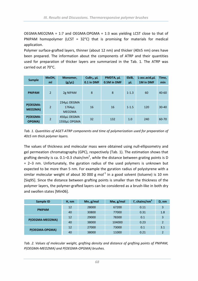
III. Results and Discussions. Thermoresponsive polymer brushes
68
OEGMA:MEO2MA = 1:7 and OEGMA:OPGMA = 1:3 was yielding LCST close to that of
PNIPAM homopolymer (LCST = 32°C) that is promising for materials for medical
application.
Polymer surface‐grafted layers, thinner (about 12 nm) and thicker (40±5 nm) ones have
been prepared. The information about the components of ATRP and their quantities
used for preparation of thicker layers are summarized in the Tab. 1. The ATRP was
carried out at 70°C.
Sample MeOH,
ml
Monomer,
(g/µL)
CuBr2, µL
0.1 in DMF
PMDTA, µL
0.5M in DMF
EbiB,
µL
L‐asc.acid,µL
1M in DMF
Time,
min
PNIPAM
2 2g NIPAM 8 8 1‐1.3 60 40‐60
P(OEGMA‐
MEO2MA) 2
234µL OEGMA
1764µL
MEO2MA
16 16 1‐1.5 120 30‐40
P(OEGMA‐
OPGMA) 2
450µL OEGMA
1550µL OPGMA 32 132 1.0 240 60‐70
Tab. 1. Quantities of AGET‐ATRP components and time of polymerization used for preparation of
40±5 nm thick polymer layers.
The values of thickness and molecular mass were obtained using null‐ellipsometry and
gel permeation chromatography (GPC), respectively (Tab. 1). The estimation shows that
grafting density is ca. 0.1–0.3 chain/nm2, while the distance between grating points is D
= 2–3 nm. Unfortunately, the gyration radius of the used polymers is unknown but
expected to be more than 5 nm. For example the gyration radius of polystyrene with a
similar molecular weight of about 30 000 g mol‐1 in a good solvent (toluene) is 10 nm
[Siq95]. Since the distance between grafting points is smaller than the thickness of the
polymer layers, the polymer‐grafted layers can be considered as a brush‐like in both dry
and swollen states [Min06].
Sample ID H, nm Mn, g/mol Mw, g/mol Γ, chains/nm2 D, nm
PNIPAM 12 28000 67200 0.11 3
40 30800 77000 0.31 1.8
P(OEGMA‐MEO2MA) 12 29000 78300 0.1 3
40 38000 104000 0.23 2
P(OEGMA‐OPGMA) 12 27000 73000 0.1 3.1
40 38000 11000 0.21 2
Tab. 2. Values of molecular weight, grafting density and distance of grafting points of PNIPAM,
P(OEGMA‐MEO2MA) and P(OEGMA‐OPGMA) brushes.
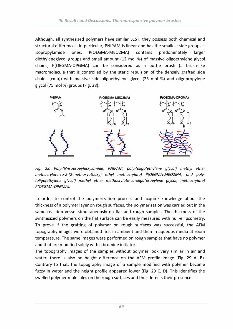
III. Results and Discussions. Thermoresponsive polymer brushes
69
Although, all synthesized polymers have similar LCST, they possess both chemical and
structural differences. In particular, PNIPAM is linear and has the smallest side groups –
isopropylamide ones, P(OEGMA‐MEO2MA) contains predominately larger
diethyleneglycol groups and small amount (12 mol %) of massive oligoethylene glycol
chains, P(OEGMA‐OPGMA) can be considered as a bottle brush (a brush‐like
macromolecule that is controlled by the steric repulsion of the densely grafted side
chains [cmu]) with massive side oligoethylene glycol (25 mol %) and oligopropylene
glycol (75 mol %) groups (Fig. 28).
H
Fig. 28. Poly‐(N‐isopropylacrylamide) PNIPAM, poly‐(oligo(ethylene glycol) methyl ether
methacrylate‐co‐2‐(2‐methoxyethoxy) ethyl methacrylate) P(OEGMA‐MEO2MA) and poly‐
(oligo(ethylene glycol) methyl ether methacrylate‐co‐oligo(propylene glycol) methacrylate)
P(OEGMA‐OPGMA).
In order to control the polymerization process and acquire knowledge about the
thickness of a polymer layer on rough surfaces, the polymerization was carried out in the
same reaction vessel simultaneously on flat and rough samples. The thickness of the
synthesized polymers on the flat surface can be easily measured with null‐ellipsometry.
To prove if the grafting of polymer on rough surfaces was successful, the AFM
topography images were obtained first in ambient and then in aqueous media at room
temperature. The same images were performed on rough samples that have no polymer
and that are modified solely with a bromide initiator.
The topography images of the samples without polymer look very similar in air and
water, there is also no height difference on the AFM profile image (Fig. 29 A, B).
Contrary to that, the topography image of a sample modified with polymer became
fuzzy in water and the height profile appeared lower (Fig. 29 C, D). This identifies the
swelled polymer molecules on the rough surfaces and thus detects their presence.
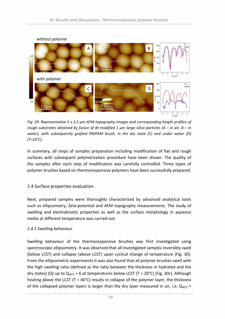
III. Results and Discussions. Thermoresponsive polymer brushes
70
0 1 2 3 4 5
0
200
400
600
800
Z, n
m
X, µm
airwater
1.00
0.00
0 1 2 3 4 5
0
200
400
600
800
Z, n
m
X, µm
airwater
1.0µm
A
1.0µm
B
1.0µm
C
1.0µm
D
without polymer
with polymer
Fig. 29. Representative 5 x 2.5 µm AFM topography images and corresponding height profiles of
rough substrates obtained by fusion of Br‐modified 1 µm large silica particles (A – in air, B – in
water), with subsequently grafted PNIPAM brush, in the dry state (C) and under water (D)
(T=24°C).
In summary, all steps of samples preparation including modification of flat and rough
surfaces with subsequent polymerization procedure have been shown. The quality of
the samples after each step of modification was carefully controlled. Three types of
polymer brushes based on thermoresponsive polymers have been successfully prepared.
1.4 Surface properties evaluation
Next, prepared samples were thoroughly characterized by advanced analytical tools
such as ellipsometry, Zeta‐potential and AFM topography measurements. The study of
swelling and electrokinetic properties as well as the surface morphology in aqueous
media at different temperature was carried out.
1.4.1 Swelling behaviour
Swelling behaviour of the thermoresponsive brushes was first investigated using
spectroscopic ellipsometry. It was observed that all investigated samples reversibly swell
(below LCST) and collapse (above LCST) upon cyclical change of temperature (Fig. 30).
From the ellipsometric experiments it was also found that all polymer brushes swell with
the high swelling ratio (defined as the ratio between the thickness in hydrated and the
dry states) (Q) up to Q20°C = 6 at temperatures below LCST (T = 20°C) (Fig. 30c). Although
heating above the LCST (T = 40°C) results in collapse of the polymer layer, the thickness
of the collapsed polymer layers is larger than the dry layer measured in air, i.e. Q40°C =
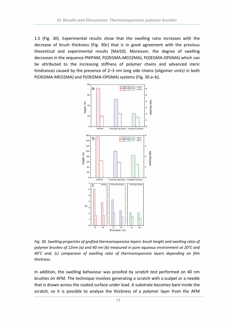
III. Results and Discussions. Thermoresponsive polymer brushes
71
1.5 (Fig. 30). Experimental results show that the swelling ratio increases with the
decrease of brush thickness (Fig. 30c) that is in good agreement with the previous
theoretical and experimental results [Mal10]. Moreover, the degree of swelling
decreases in the sequence PNIPAM, P(OEGMA‐MEO2MA), P(OEGMA‐OPGMA) which can
be attributed to the increasing stiffness of polymer chains and advanced steric
hindrances caused by the presence of 2–3 nm long side chains (oligomer units) in both
P(OEGMA‐MEO2MA) and P(OEGMA‐OPGMA) systems (Fig. 30 a–b).
Fig. 30. Swelling properties of grafted thermoresponsive layers: brush height and swelling ratio of
polymer brushes of 12nm (a) and 40 nm (b) measured in pure aqueous environment at 20°C and
40°C and; (c) comparison of swelling ratio of thermoresponsive layers depending on film
thickness.
In addition, the swelling behaviour was proofed by scratch test performed on 40 nm
brushes on AFM. The technique involves generating a scratch with a scalpel or a needle
that is drawn across the coated surface under load. A substrate becomes bare inside the
scratch, so it is possible to analyse the thickness of a polymer layer from the AFM
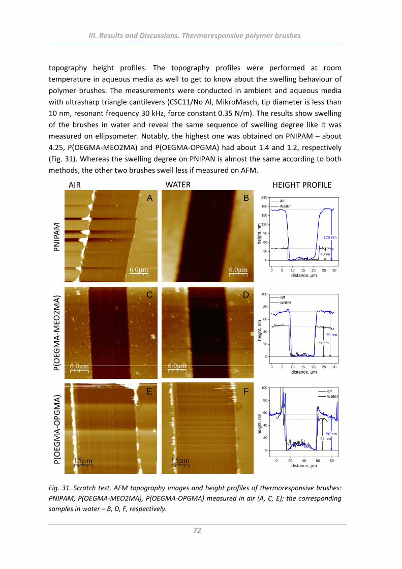
III. Results and Discussions. Thermoresponsive polymer brushes
72
topography height profiles. The topography profiles were performed at room
temperature in aqueous media as well to get to know about the swelling behaviour of
polymer brushes. The measurements were conducted in ambient and aqueous media
with ultrasharp triangle cantilevers (CSC11/No Al, MikroMasch, tip diameter is less than
10 nm, resonant frequency 30 kHz, force constant 0.35 N/m). The results show swelling
of the brushes in water and reveal the same sequence of swelling degree like it was
measured on ellipsometer. Notably, the highest one was obtained on PNIPAM – about
4.25, P(OEGMA‐MEO2MA) and P(OEGMA‐OPGMA) had about 1.4 and 1.2, respectively
(Fig. 31). Whereas the swelling degree on PNIPAN is almost the same according to both
methods, the other two brushes swell less if measured on AFM.
0 5 10 15 20 25 30
0
20
40
60
80
100
heig
ht, n
m
distance, µm
air water
70 nm
50nm
0 5 10 15 20 25 30
0
30
60
90
120
150
180
210
heig
ht, n
m
distance, µm
air water
170 nm
40nm
0 20 40 60 80
0
20
40
60
80
100
heig
ht, n
m
distance, µm
air water
48 nm58 nm
PNIPAM
P(OEG
MA‐M
EO2MA)
P(OEG
MA‐OPGMA)
AIR WATER HEIGHT PROFILE
A
E
DC
B
F
Fig. 31. Scratch test. AFM topography images and height profiles of thermoresponsive brushes:
PNIPAM, P(OEGMA‐MEO2MA), P(OEGMA‐OPGMA) measured in air (A, C, E); the corresponding
samples in water – B, D, F, respectively.
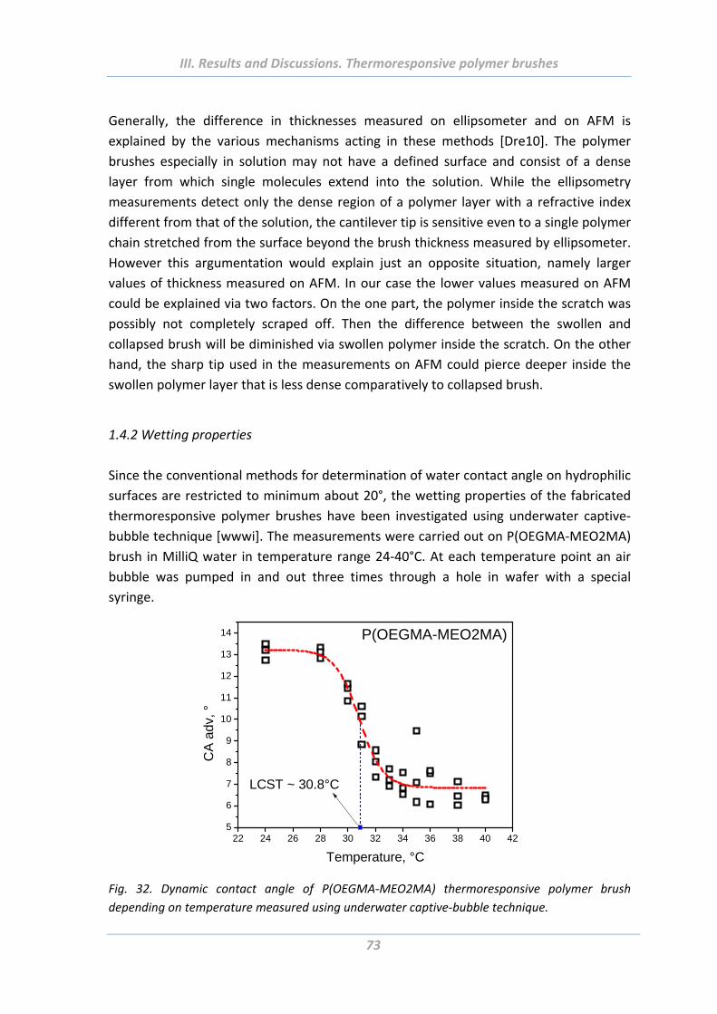
III. Results and Discussions. Thermoresponsive polymer brushes
73
Generally, the difference in thicknesses measured on ellipsometer and on AFM is
explained by the various mechanisms acting in these methods [Dre10]. The polymer
brushes especially in solution may not have a defined surface and consist of a dense
layer from which single molecules extend into the solution. While the ellipsometry
measurements detect only the dense region of a polymer layer with a refractive index
different from that of the solution, the cantilever tip is sensitive even to a single polymer
chain stretched from the surface beyond the brush thickness measured by ellipsometer.
However this argumentation would explain just an opposite situation, namely larger
values of thickness measured on AFM. In our case the lower values measured on AFM
could be explained via two factors. On the one part, the polymer inside the scratch was
possibly not completely scraped off. Then the difference between the swollen and
collapsed brush will be diminished via swollen polymer inside the scratch. On the other
hand, the sharp tip used in the measurements on AFM could pierce deeper inside the
swollen polymer layer that is less dense comparatively to collapsed brush.
1.4.2 Wetting properties
Since the conventional methods for determination of water contact angle on hydrophilic
surfaces are restricted to minimum about 20°, the wetting properties of the fabricated
thermoresponsive polymer brushes have been investigated using underwater captive‐
bubble technique [wwwi]. The measurements were carried out on P(OEGMA‐MEO2MA)
brush in MilliQ water in temperature range 24‐40°C. At each temperature point an air
bubble was pumped in and out three times through a hole in wafer with a special
syringe.
22 24 26 28 30 32 34 36 38 40 425
6
7
8
9
10
11
12
13
14
CA
adv
, °
Temperature, °C
P(OEGMA-MEO2MA)
LCST ~ 30.8°C
Fig. 32. Dynamic contact angle of P(OEGMA‐MEO2MA) thermoresponsive polymer brush
depending on temperature measured using underwater captive‐bubble technique.
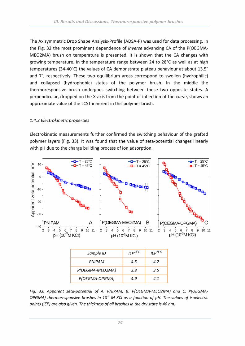
III. Results and Discussions. Thermoresponsive polymer brushes
74
The Axisymmetric Drop Shape Analysis‐Profile (ADSA‐P) was used for data processing. In
the Fig. 32 the most prominent dependence of inverse advancing CA of the P(OEGMA‐
MEO2MA) brush on temperature is presented. It is shown that the CA changes with
growing temperature. In the temperature range between 24 to 28°C as well as at high
temperatures (34‐40°C) the values of CA demonstrate plateau behaviour at about 13.5°
and 7°, respectively. These two equilibrium areas correspond to swollen (hydrophilic)
and collapsed (hydrophobic) states of the polymer brush. In the middle the
thermoresponsive brush undergoes switching between these two opposite states. A
perpendicular, dropped on the X‐axis from the point of inflection of the curve, shows an
approximate value of the LCST inherent in this polymer brush.
1.4.3 Electrokinetic properties
Electrokinetic measurements further confirmed the switching behaviour of the grafted
polymer layers (Fig. 33). It was found that the value of zeta‐potential changes linearly
with pH due to the charge building process of ion adsorption.
2 3 4 5 6 7 8 9 10 11-40
-30
-20
-10
0
10 T = 25°C T = 45°C
App
aren
t ze
ta p
oten
tial,
mV
pH (10-3M KCI)
PNIPAM A2 3 4 5 6 7 8 9 10 11
P(OEGMA-OPGMA)
T = 25°C T = 45°C
pH (10-3M KCl)
C2 3 4 5 6 7 8 9 10 11
P(OEGMA-MEO2MA)
pH (10-3M KCl)
T = 25°C T = 45°C
B
Sample ID IEP25°C IEP45°C
PNIPAM 4.5 4.2
P(OEGMA‐MEO2MA) 3.8 3.5
P(OEGMA‐OPGMA) 4.9 4.1
Fig. 33. Apparent zeta‐potential of A: PNIPAM, B: P(OEGMA‐MEO2MA) and C: P(OEGMA‐
OPGMA) thermoresponsive brushes in 10‐3 M KCl as a function of pH. The values of isoelectric
points (IEP) are also given. The thickness of all brushes in the dry state is 40 nm.
III. Results and Discussions. Thermoresponsive polymer brushes
75
Since the investigated thermoresponsive brushes do not have dissociating groups, the
change in the absolute value of zeta potential with pH is caused by the preferential
adsorption of hydroxyl (OH‐) or Cl‐ ions at pH > IEP and protons (H+) pH < IEP from the
electrolyte solution, respectively. Investigated films showed a flattish curve at 25°C (Fig.
33, blue curves). This behaviour can be attributed mainly to the strong swelling of
polymer layers as was previously confirmed by ellipsometry measurements and scratch
test and with it a high amount of adsorbed water or rather an open structure of the
surface. On the other hand, apparent zeta potential changed strongly upon the heating
cycle for all systems (Fig. 33), when phase transition from the swollen hydrophilic to
collapsed hydrophobic state is observed. In this case the adsorption equilibrium state is
more at the site of ion adsorption. Hence the absolute value of zeta‐potential increases.
It was observed that absolute values of zeta‐potential of all thermoresponsive brushes
reversibly increased upon the collapse of polymer layers at temperatures above the
LCST (Fig. 33, red curves).
1.4.4 Surface morphology
Switching of surface topography was tested at room temperature (24°C) and at 40°C.
The samples of two different values of brush thickness were investigated. For AFM
imaging in water contact mode fluid cell was used. For topography measurements silicon
tips with radius <10 nm, spring constant of 0.35 N/m and resonance frequency of 20–40
kHz (CSC11, Micromasch) were chosen. The morphology of all 40 nm thick layers
remains smooth (rms = 1 nm), independent of the state of the polymer: either swollen
or collapsed. Collapse of thinner (hdry = 12 nm) layers results however in a change of
morphology from smooth and featureless below the LCST to rough one above LCST (Fig.
34, results presented for PNIPAM). The rough morphology may originate from the
collapse of grafted polymer chains and formation of micelle‐like morphology. For the
two other systems P(OEGMA‐MEO2MA) and P(OEGMA‐OPGMA) the thermoresponsive
films reveal smooth homogeneous surfaces both at elevated and ambient temperatures.
This can be explained by steric hindrance arises from long and bulky side chains of
P(OEGMA‐MEO2MA) and P(OEGMA‐OPGMA) systems that prevent them from such
effective collapsed state observed for PNIPAM.
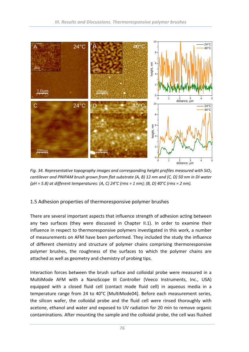
III. Results and Discussions. Thermoresponsive polymer brushes
76
1000nm
200nm
1.0µm
200nm
24°C 40°CA B
1000nm
C 24°C
1000nm
D 40°C
0 1 2 3 4 50
2
4
6
8
10 24°C 40°C
hei
ght,
nm
distance, µm
0 1 2 3 4 50
2
4
6
8
10 24°C 40°C
heig
ht,
nm
distance, µm
Fig. 34. Representative topography images and corresponding height profiles measured with SiO2
cantilever and PNIPAM brush grown from flat substrate (A, B) 12 nm and (C, D) 50 nm in DI water
(pH = 5.8) at different temperatures: (A, C) 24°C (rms = 1 nm); (B, D) 40°C (rms = 2 nm).
1.5 Adhesion properties of thermoresponsive polymer brushes
There are several important aspects that influence strength of adhesion acting between
any two surfaces (they were discussed in Chapter II.1). In order to examine their
influence in respect to thermoresponsive polymers investigated in this work, a number
of measurements on AFM have been performed. They included the study the influence
of different chemistry and structure of polymer chains comprising thermoresponsive
polymer brushes, the roughness of the surfaces to which the polymer chains are
attached as well as geometry and chemistry of probing tips.
Interaction forces between the brush surface and colloidal probe were measured in a
MultiMode AFM with a NanoScope III Controller (Veeco Instruments, Inc., USA)
equipped with a closed fluid cell (contact mode fluid cell) in aqueous media in a
temperature range from 24 to 40°C [MultiMode04]. Before each measurement series,
the silicon wafer, the colloidal probe and the fluid cell were rinsed thoroughly with
acetone, ethanol and water and exposed to UV radiation for 20 min to remove organic
contaminations. After mounting the sample and the colloidal probe, the cell was flushed
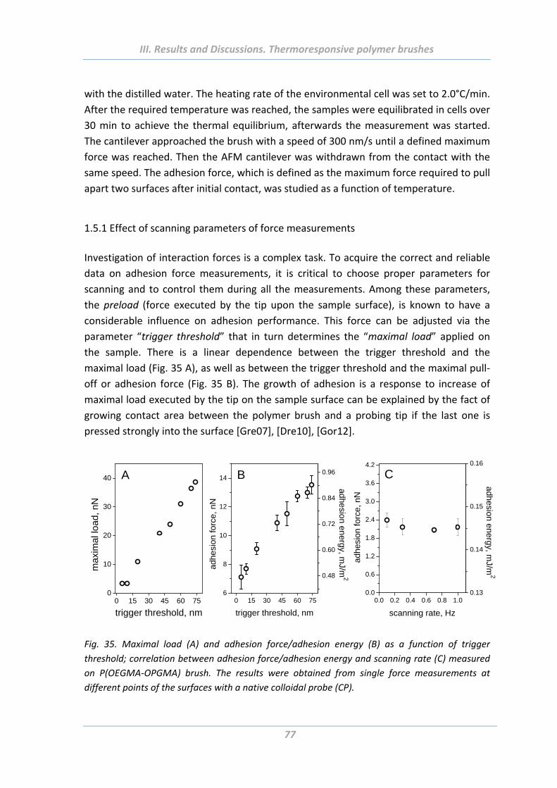
III. Results and Discussions. Thermoresponsive polymer brushes
77
with the distilled water. The heating rate of the environmental cell was set to 2.0°C/min.
After the required temperature was reached, the samples were equilibrated in cells over
30 min to achieve the thermal equilibrium, afterwards the measurement was started.
The cantilever approached the brush with a speed of 300 nm/s until a defined maximum
force was reached. Then the AFM cantilever was withdrawn from the contact with the
same speed. The adhesion force, which is defined as the maximum force required to pull
apart two surfaces after initial contact, was studied as a function of temperature.
1.5.1 Effect of scanning parameters of force measurements
Investigation of interaction forces is a complex task. To acquire the correct and reliable
data on adhesion force measurements, it is critical to choose proper parameters for
scanning and to control them during all the measurements. Among these parameters,
the preload (force executed by the tip upon the sample surface), is known to have a
considerable influence on adhesion performance. This force can be adjusted via the
parameter “trigger threshold” that in turn determines the “maximal load” applied on
the sample. There is a linear dependence between the trigger threshold and the
maximal load (Fig. 35 A), as well as between the trigger threshold and the maximal pull‐
off or adhesion force (Fig. 35 B). The growth of adhesion is a response to increase of
maximal load executed by the tip on the sample surface can be explained by the fact of
growing contact area between the polymer brush and a probing tip if the last one is
pressed strongly into the surface [Gre07], [Dre10], [Gor12].
0 15 30 45 60 750
10
20
30
40
maxi
mal
load,
nN
trigger threshold, nm
A
0 15 30 45 60 756
8
10
12
14
trigger threshold, nm
adhe
sion
forc
e, n
N
0.48
0.60
0.72
0.84
0.96
adhe
sion en
ergy, mJ/m
2
B
0.0 0.2 0.4 0.6 0.8 1.00.0
0.6
1.2
1.8
2.4
3.0
3.6
4.2
adhe
sion
forc
e, n
N
scanning rate, Hz
0.13
0.14
0.15
0.16
adh
esion en
ergy, mJ/m
2
C
Fig. 35. Maximal load (A) and adhesion force/adhesion energy (B) as a function of trigger
threshold; correlation between adhesion force/adhesion energy and scanning rate (C) measured
on P(OEGMA‐OPGMA) brush. The results were obtained from single force measurements at
different points of the surfaces with a native colloidal probe (CP).
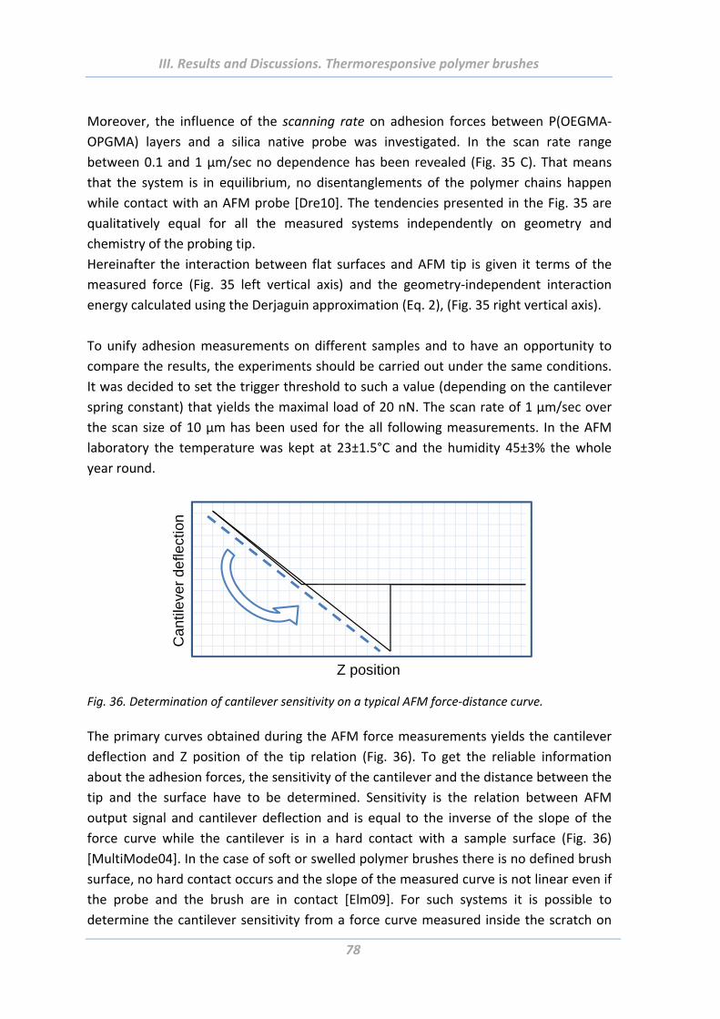
III. Results and Discussions. Thermoresponsive polymer brushes
78
Moreover, the influence of the scanning rate on adhesion forces between P(OEGMA‐
OPGMA) layers and a silica native probe was investigated. In the scan rate range
between 0.1 and 1 µm/sec no dependence has been revealed (Fig. 35 C). That means
that the system is in equilibrium, no disentanglements of the polymer chains happen
while contact with an AFM probe [Dre10]. The tendencies presented in the Fig. 35 are
qualitatively equal for all the measured systems independently on geometry and
chemistry of the probing tip.
Hereinafter the interaction between flat surfaces and AFM tip is given it terms of the
measured force (Fig. 35 left vertical axis) and the geometry‐independent interaction
energy calculated using the Derjaguin approximation (Eq. 2), (Fig. 35 right vertical axis).
To unify adhesion measurements on different samples and to have an opportunity to
compare the results, the experiments should be carried out under the same conditions.
It was decided to set the trigger threshold to such a value (depending on the cantilever
spring constant) that yields the maximal load of 20 nN. The scan rate of 1 µm/sec over
the scan size of 10 µm has been used for the all following measurements. In the AFM
laboratory the temperature was kept at 23±1.5°C and the humidity 45±3% the whole
year round.
Z position
Can
tilev
erde
flect
ion
Fig. 36. Determination of cantilever sensitivity on a typical AFM force‐distance curve.
The primary curves obtained during the AFM force measurements yields the cantilever
deflection and Z position of the tip relation (Fig. 36). To get the reliable information
about the adhesion forces, the sensitivity of the cantilever and the distance between the
tip and the surface have to be determined. Sensitivity is the relation between AFM
output signal and cantilever deflection and is equal to the inverse of the slope of the
force curve while the cantilever is in a hard contact with a sample surface (Fig. 36)
[MultiMode04]. In the case of soft or swelled polymer brushes there is no defined brush
surface, no hard contact occurs and the slope of the measured curve is not linear even if
the probe and the brush are in contact [Elm09]. For such systems it is possible to
determine the cantilever sensitivity from a force curve measured inside the scratch on
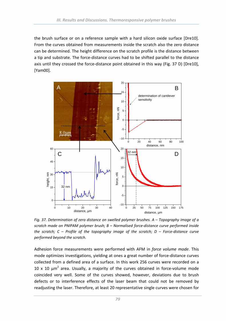
III. Results and Discussions. Thermoresponsive polymer brushes
79
the brush surface or on a reference sample with a hard silicon oxide surface [Dre10].
From the curves obtained from measurements inside the scratch also the zero distance
can be determined. The height difference on the scratch profile is the distance between
a tip and substrate. The force‐distance curves had to be shifted parallel to the distance
axis until they crossed the force‐distance point obtained in this way (Fig. 37 D) [Dre10],
[Yam00].
A
0 20 40 60 80 100-10
-5
0
5
10
15
20
forc
e, n
N
distance, nm
determination of cantileversensitivity
B
0 10 20 30 40
0
15
30
45
60
heig
ht,
nm
distance, µm
32 nm
C
0 25 50 75 100 125 150 175-10
-5
0
5
10
15
20
forc
e, n
N
distance, µm
32 nm D
Fig. 37. Determination of zero distance on swelled polymer brushes. A – Topography image of a
scratch made on PNIPAM polymer brush; B – Normalised force‐distance curve performed inside
the scratch; C – Profile of the topography image of the scratch; D – Force‐distance curve
performed beyond the scratch.
Adhesion force measurements were performed with AFM in force volume mode. This
mode optimizes investigations, yielding at ones a great number of force‐distance curves
collected from a defined area of a surface. In this work 256 curves were recorded on a
10 x 10 µm2 area. Usually, a majority of the curves obtained in force‐volume mode
coincided very well. Some of the curves showed, however, deviations due to brush
defects or to interference effects of the laser beam that could not be removed by
readjusting the laser. Therefore, at least 20 representative single curves were chosen for
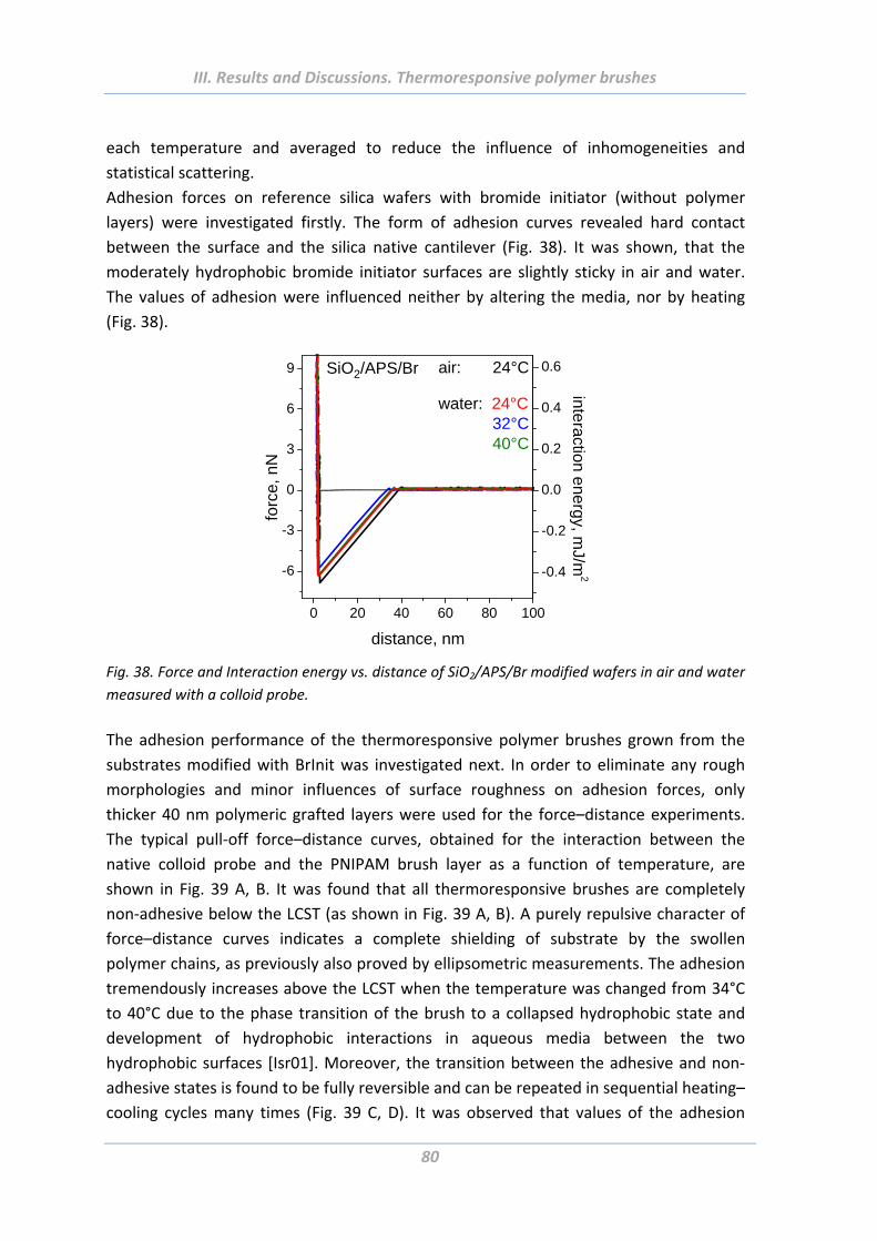
III. Results and Discussions. Thermoresponsive polymer brushes
80
each temperature and averaged to reduce the influence of inhomogeneities and
statistical scattering.
Adhesion forces on reference silica wafers with bromide initiator (without polymer
layers) were investigated firstly. The form of adhesion curves revealed hard contact
between the surface and the silica native cantilever (Fig. 38). It was shown, that the
moderately hydrophobic bromide initiator surfaces are slightly sticky in air and water.
The values of adhesion were influenced neither by altering the media, nor by heating
(Fig. 38).
0 20 40 60 80 100
-6
-3
0
3
6
9 air: 24°C
water: 24°C 32°C 40°C
SiO2/APS/Br
distance, nm
forc
e, n
N
-0.4
-0.2
0.0
0.2
0.4
0.6
interaction energy, mJ/m
2
Fig. 38. Force and Interaction energy vs. distance of SiO2/APS/Br modified wafers in air and water
measured with a colloid probe.
The adhesion performance of the thermoresponsive polymer brushes grown from the
substrates modified with BrInit was investigated next. In order to eliminate any rough
morphologies and minor influences of surface roughness on adhesion forces, only
thicker 40 nm polymeric grafted layers were used for the force–distance experiments.
The typical pull‐off force–distance curves, obtained for the interaction between the
native colloid probe and the PNIPAM brush layer as a function of temperature, are
shown in Fig. 39 A, B. It was found that all thermoresponsive brushes are completely
non‐adhesive below the LCST (as shown in Fig. 39 A, B). A purely repulsive character of
force–distance curves indicates a complete shielding of substrate by the swollen
polymer chains, as previously also proved by ellipsometric measurements. The adhesion
tremendously increases above the LCST when the temperature was changed from 34°C
to 40°C due to the phase transition of the brush to a collapsed hydrophobic state and
development of hydrophobic interactions in aqueous media between the two
hydrophobic surfaces [Isr01]. Moreover, the transition between the adhesive and non‐
adhesive states is found to be fully reversible and can be repeated in sequential heating–
cooling cycles many times (Fig. 39 C, D). It was observed that values of the adhesion
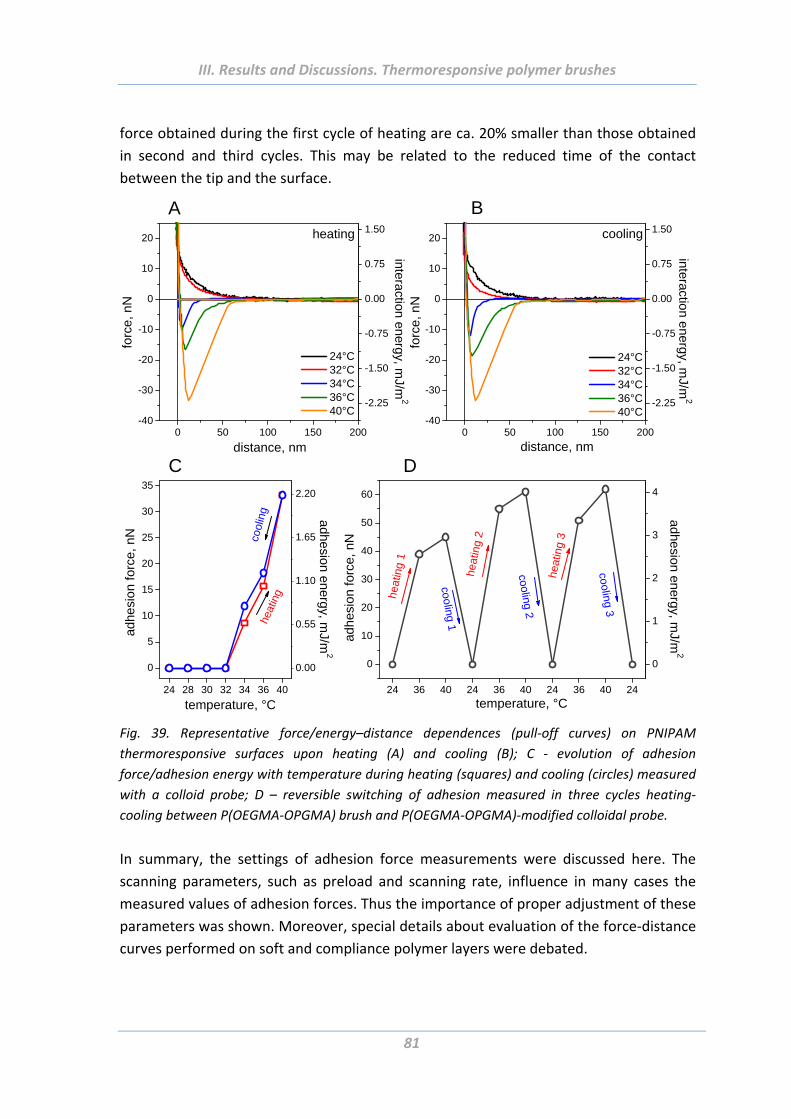
III. Results and Discussions. Thermoresponsive polymer brushes
81
force obtained during the first cycle of heating are ca. 20% smaller than those obtained
in second and third cycles. This may be related to the reduced time of the contact
between the tip and the surface.
0 50 100 150 200-40
-30
-20
-10
0
10
20
24°C 32°C 34°C 36°C 40°C
forc
e, n
N
distance, nm
heating
-2.25
-1.50
-0.75
0.00
0.75
1.50
interaction
energ
y, mJ/m
2
A
0 50 100 150 200-40
-30
-20
-10
0
10
20
24°C 32°C 34°C 36°C 40°C
forc
e, n
N
distance, nm
cooling
-2.25
-1.50
-0.75
0.00
0.75
1.50
interactio
n ene
rgy, mJ/m
2
B
24 28 30 32 34 36 40
0
5
10
15
20
25
30
35
cool
ing
adhe
sio
n fo
rce,
nN
temperature, °C
heat
ing
0.00
0.55
1.10
1.65
2.20
adhesion energy, mJ/m
2C
24 36 40 24 36 40 24 36 40 24
0
10
20
30
40
50
60
cooling 3
cooling 2
heat
ing
3
heat
ing
2
adhes
ion
forc
e, n
N
temperature, °C
heat
ing
1
cooling 1
0
1
2
3
4
adhe
sion en
ergy, m
J/m2
D
Fig. 39. Representative force/energy–distance dependences (pull‐off curves) on PNIPAM
thermoresponsive surfaces upon heating (A) and cooling (B); C ‐ evolution of adhesion
force/adhesion energy with temperature during heating (squares) and cooling (circles) measured
with a colloid probe; D – reversible switching of adhesion measured in three cycles heating‐
cooling between P(OEGMA‐OPGMA) brush and P(OEGMA‐OPGMA)‐modified colloidal probe.
In summary, the settings of adhesion force measurements were discussed here. The
scanning parameters, such as preload and scanning rate, influence in many cases the
measured values of adhesion forces. Thus the importance of proper adjustment of these
parameters was shown. Moreover, special details about evaluation of the force‐distance
curves performed on soft and compliance polymer layers were debated.
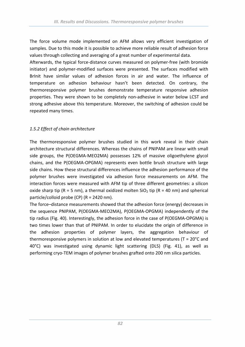
III. Results and Discussions. Thermoresponsive polymer brushes
82
The force volume mode implemented on AFM allows very efficient investigation of
samples. Due to this mode it is possible to achieve more reliable result of adhesion force
values through collecting and averaging of a great number of experimental data.
Afterwards, the typical force‐distance curves measured on polymer‐free (with bromide
initiator) and polymer‐modified surfaces were presented. The surfaces modified with
BrInit have similar values of adhesion forces in air and water. The influence of
temperature on adhesion behaviour hasn’t been detected. On contrary, the
thermoresponsive polymer brushes demonstrate temperature responsive adhesion
properties. They were shown to be completely non‐adhesive in water below LCST and
strong adhesive above this temperature. Moreover, the switching of adhesion could be
repeated many times.
1.5.2 Effect of chain architecture
The thermoresponsive polymer brushes studied in this work reveal in their chain
architecture structural differences. Whereas the chains of PNIPAM are linear with small
side groups, the P(OEGMA‐MEO2MA) possesses 12% of massive oligoethylene glycol
chains, and the P(OEGMA‐OPGMA) represents even bottle brush structure with large
side chains. How these structural differences influence the adhesion performance of the
polymer brushes were investigated via adhesion force measurements on AFM. The
interaction forces were measured with AFM tip of three different geometries: a silicon
oxide sharp tip (R = 5 nm), a thermal oxidized molten SiO2 tip (R = 40 nm) and spherical
particle/colloid probe (CP) (R = 2420 nm).
The force–distance measurements showed that the adhesion force (energy) decreases in
the sequence PNIPAM, P(OEGMA‐MEO2MA), P(OEGMA‐OPGMA) independently of the
tip radius (Fig. 40). Interestingly, the adhesion force in the case of P(OEGMA‐OPGMA) is
two times lower than that of PNIPAM. In order to elucidate the origin of difference in
the adhesion properties of polymer layers, the aggregation behaviour of
thermoresponsive polymers in solution at low and elevated temperatures (T = 20°C and
40°C) was investigated using dynamic light scattering (DLS) (Fig. 41), as well as
performing cryo‐TEM images of polymer brushes grafted onto 200 nm silica particles.
III. Results and Discussions. Thermoresponsive polymer brushes
83
Fig. 40. Adhesion force and adhesion energy of different thermoresponsive polymer brushes
(thickness =40 nm) measured by three kinds of AFM probes: (a) sharp tip with radius 5 nm, (b)
molten tip with radius 40 nm, (c) sphere with radius 2420 nm. T = 40°C.
It was found that polymer chains form aggregates with sizes of about 20–40 nm at 20°C
that are comparable with the size of single polymer chains. An increase of the
temperature above the LSCT resulted in the formation of larger aggregates with sizes
100–200 nm caused by the sticking of hydrophobic polymer chains together. Notably,
the size of the aggregates formed at elevated temperatures decrease in the same
sequence as adhesion decreases: PNIPAM, P(OEGMA‐MEO2MA), P(OEGMA‐OPGMA)
(Fig. 41 a, b). On the other hand, it is well known that a higher amount of stabilizing
groups leads to the formation of smaller aggregates. Therefore, the size reduction of
aggregates effect in the sequence PNIPAM, P(OEGMA‐MEO2MA), P(OEGMA‐OPGMA)
might be attributed to the increasing fraction of hydrophilic oligoethylene glycol (OEG)
groups: PNIPAM does not contain OEG, P(OEGMA‐MEO2MA) and P(OEGMA‐OPGMA)
contain 12 mol % and 25 mol % of OEG, respectively. These OEG groups stabilize the
polymer aggregates by formation of a hydrated and non‐adhesive OEG shell around the
hydrophobic core.
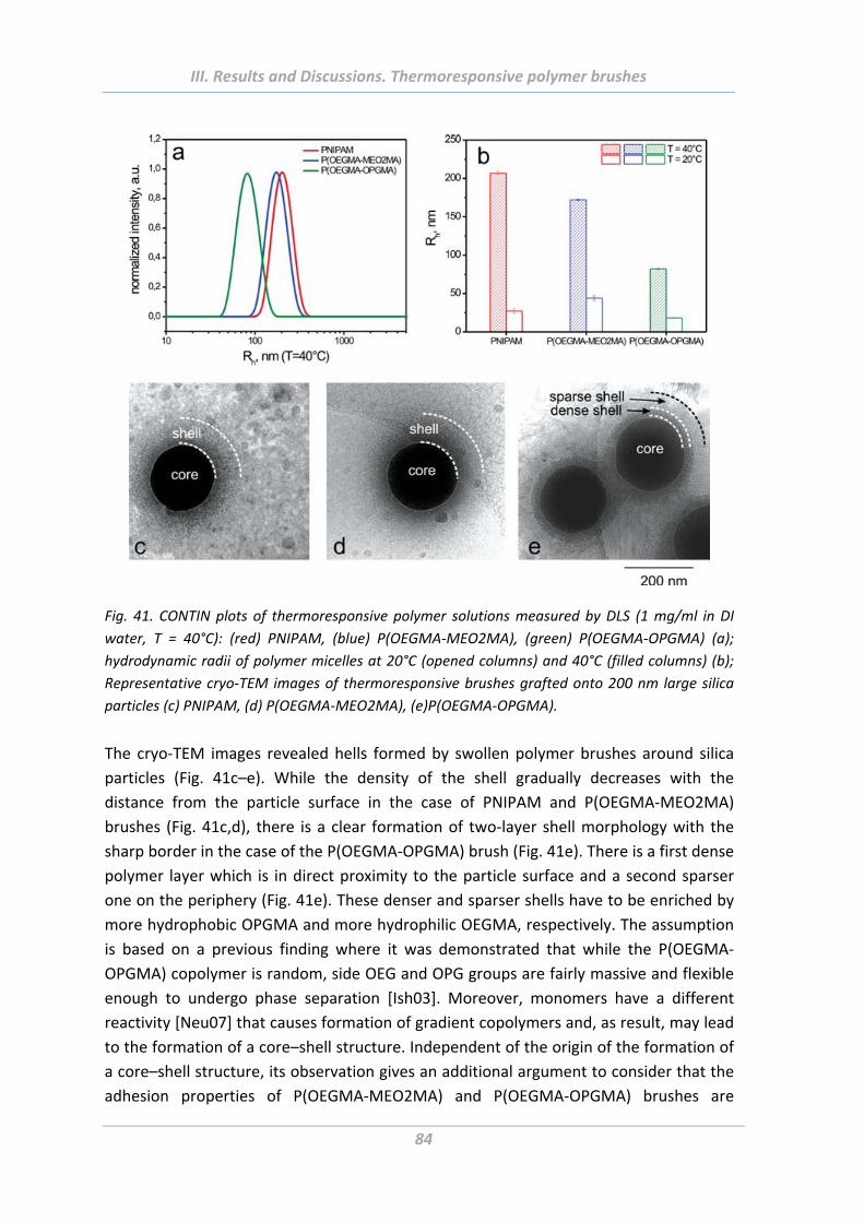
III. Results and Discussions. Thermoresponsive polymer brushes
84
Fig. 41. CONTIN plots of thermoresponsive polymer solutions measured by DLS (1 mg/ml in DI
water, T = 40°C): (red) PNIPAM, (blue) P(OEGMA‐MEO2MA), (green) P(OEGMA‐OPGMA) (a);
hydrodynamic radii of polymer micelles at 20°C (opened columns) and 40°C (filled columns) (b);
Representative cryo‐TEM images of thermoresponsive brushes grafted onto 200 nm large silica
particles (c) PNIPAM, (d) P(OEGMA‐MEO2MA), (e)P(OEGMA‐OPGMA).
The cryo‐TEM images revealed hells formed by swollen polymer brushes around silica
particles (Fig. 41c–e). While the density of the shell gradually decreases with the
distance from the particle surface in the case of PNIPAM and P(OEGMA‐MEO2MA)
brushes (Fig. 41c,d), there is a clear formation of two‐layer shell morphology with the
sharp border in the case of the P(OEGMA‐OPGMA) brush (Fig. 41e). There is a first dense
polymer layer which is in direct proximity to the particle surface and a second sparser
one on the periphery (Fig. 41e). These denser and sparser shells have to be enriched by
more hydrophobic OPGMA and more hydrophilic OEGMA, respectively. The assumption
is based on a previous finding where it was demonstrated that while the P(OEGMA‐
OPGMA) copolymer is random, side OEG and OPG groups are fairly massive and flexible
enough to undergo phase separation [Ish03]. Moreover, monomers have a different
reactivity [Neu07] that causes formation of gradient copolymers and, as result, may lead
to the formation of a core–shell structure. Independent of the origin of the formation of
a core–shell structure, its observation gives an additional argument to consider that the
adhesion properties of P(OEGMA‐MEO2MA) and P(OEGMA‐OPGMA) brushes are
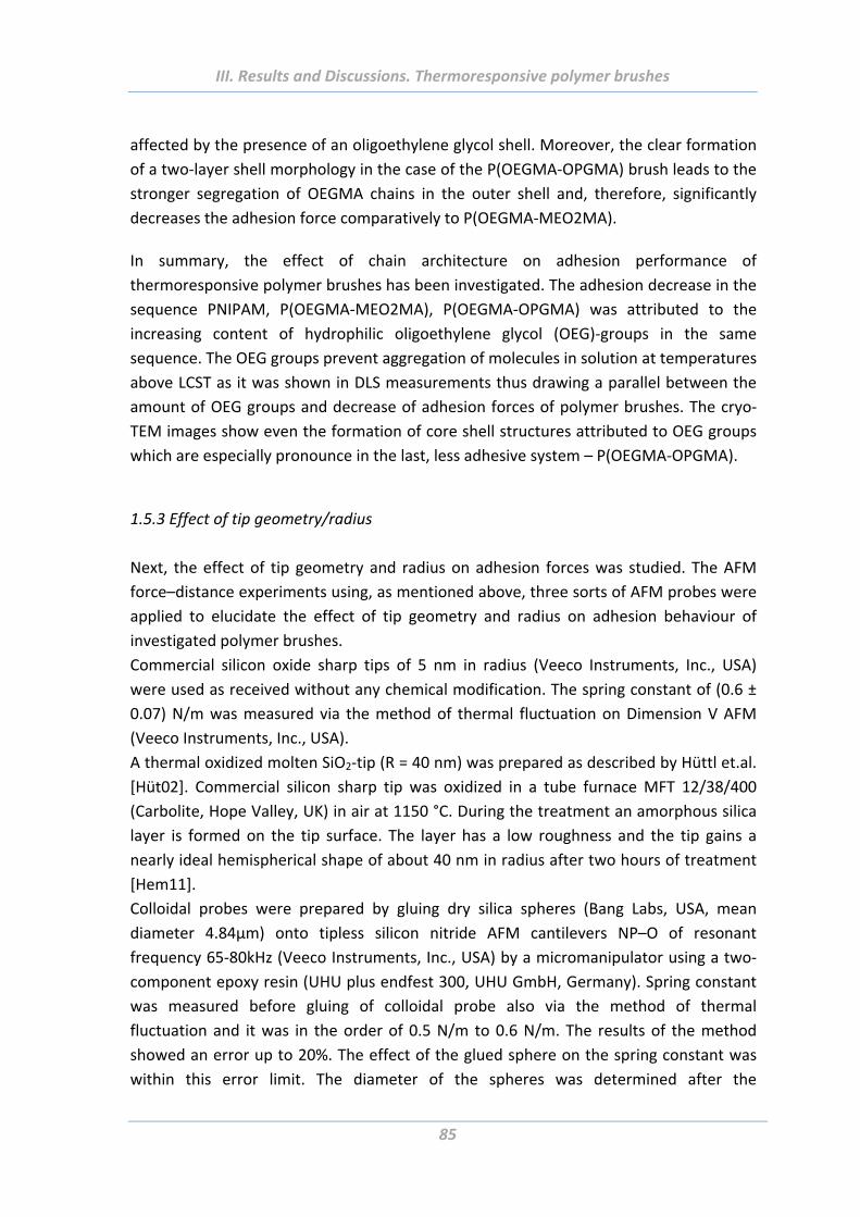
III. Results and Discussions. Thermoresponsive polymer brushes
85
affected by the presence of an oligoethylene glycol shell. Moreover, the clear formation
of a two‐layer shell morphology in the case of the P(OEGMA‐OPGMA) brush leads to the
stronger segregation of OEGMA chains in the outer shell and, therefore, significantly
decreases the adhesion force comparatively to P(OEGMA‐MEO2MA).
In summary, the effect of chain architecture on adhesion performance of
thermoresponsive polymer brushes has been investigated. The adhesion decrease in the
sequence PNIPAM, P(OEGMA‐MEO2MA), P(OEGMA‐OPGMA) was attributed to the
increasing content of hydrophilic oligoethylene glycol (OEG)‐groups in the same
sequence. The OEG groups prevent aggregation of molecules in solution at temperatures
above LCST as it was shown in DLS measurements thus drawing a parallel between the
amount of OEG groups and decrease of adhesion forces of polymer brushes. The cryo‐
TEM images show even the formation of core shell structures attributed to OEG groups
which are especially pronounce in the last, less adhesive system – P(OEGMA‐OPGMA).
1.5.3 Effect of tip geometry/radius
Next, the effect of tip geometry and radius on adhesion forces was studied. The AFM
force–distance experiments using, as mentioned above, three sorts of AFM probes were
applied to elucidate the effect of tip geometry and radius on adhesion behaviour of
investigated polymer brushes.
Commercial silicon oxide sharp tips of 5 nm in radius (Veeco Instruments, Inc., USA)
were used as received without any chemical modification. The spring constant of (0.6 ±
0.07) N/m was measured via the method of thermal fluctuation on Dimension V AFM
(Veeco Instruments, Inc., USA).
A thermal oxidized molten SiO2‐tip (R = 40 nm) was prepared as described by Hüttl et.al.
[Hüt02]. Commercial silicon sharp tip was oxidized in a tube furnace MFT 12/38/400
(Carbolite, Hope Valley, UK) in air at 1150 °C. During the treatment an amorphous silica
layer is formed on the tip surface. The layer has a low roughness and the tip gains a
nearly ideal hemispherical shape of about 40 nm in radius after two hours of treatment
[Hem11].
Colloidal probes were prepared by gluing dry silica spheres (Bang Labs, USA, mean
diameter 4.84µm) onto tipless silicon nitride AFM cantilevers NP–O of resonant
frequency 65‐80kHz (Veeco Instruments, Inc., USA) by a micromanipulator using a two‐
component epoxy resin (UHU plus endfest 300, UHU GmbH, Germany). Spring constant
was measured before gluing of colloidal probe also via the method of thermal
fluctuation and it was in the order of 0.5 N/m to 0.6 N/m. The results of the method
showed an error up to 20%. The effect of the glued sphere on the spring constant was
within this error limit. The diameter of the spheres was determined after the
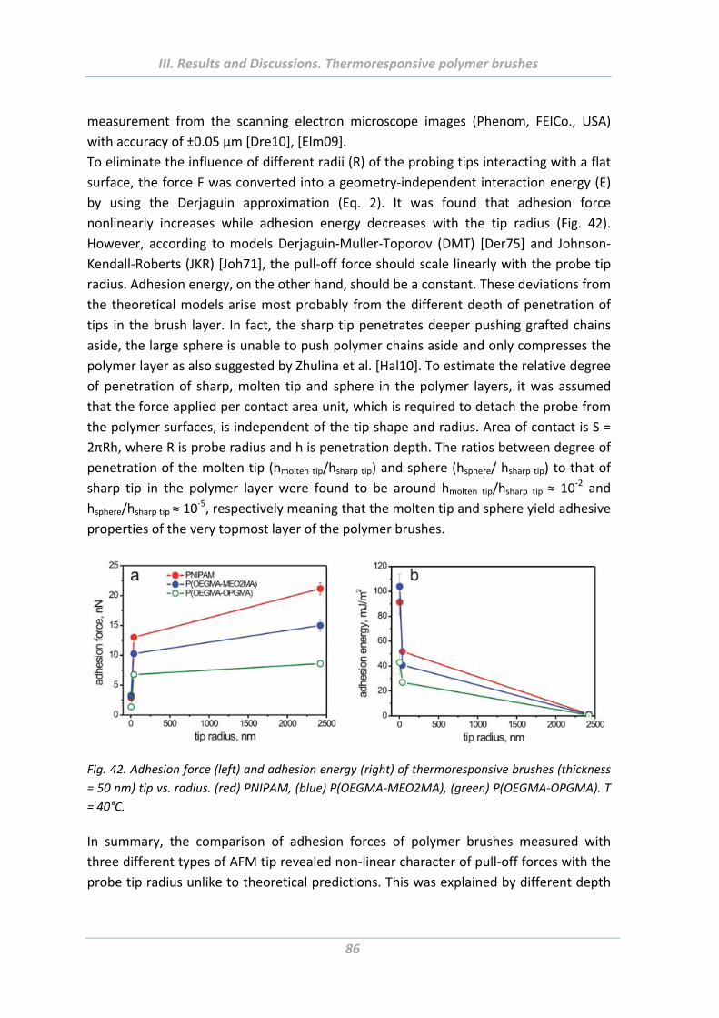
III. Results and Discussions. Thermoresponsive polymer brushes
86
measurement from the scanning electron microscope images (Phenom, FEICo., USA)
with accuracy of ±0.05 µm [Dre10], [Elm09].
To eliminate the influence of different radii (R) of the probing tips interacting with a flat
surface, the force F was converted into a geometry‐independent interaction energy (E)
by using the Derjaguin approximation (Eq. 2). It was found that adhesion force
nonlinearly increases while adhesion energy decreases with the tip radius (Fig. 42).
However, according to models Derjaguin‐Muller‐Toporov (DMT) [Der75] and Johnson‐
Kendall‐Roberts (JKR) [Joh71], the pull‐off force should scale linearly with the probe tip
radius. Adhesion energy, on the other hand, should be a constant. These deviations from
the theoretical models arise most probably from the different depth of penetration of
tips in the brush layer. In fact, the sharp tip penetrates deeper pushing grafted chains
aside, the large sphere is unable to push polymer chains aside and only compresses the
polymer layer as also suggested by Zhulina et al. [Hal10]. To estimate the relative degree
of penetration of sharp, molten tip and sphere in the polymer layers, it was assumed
that the force applied per contact area unit, which is required to detach the probe from
the polymer surfaces, is independent of the tip shape and radius. Area of contact is S =
2πRh, where R is probe radius and h is penetration depth. The ratios between degree of
penetration of the molten tip (hmolten tip/hsharp tip) and sphere (hsphere/ hsharp tip) to that of
sharp tip in the polymer layer were found to be around hmolten tip/hsharp tip ≈ 10‐2 and
hsphere/hsharp tip ≈ 10‐5, respectively meaning that the molten tip and sphere yield adhesive
properties of the very topmost layer of the polymer brushes.
Fig. 42. Adhesion force (left) and adhesion energy (right) of thermoresponsive brushes (thickness
= 50 nm) tip vs. radius. (red) PNIPAM, (blue) P(OEGMA‐MEO2MA), (green) P(OEGMA‐OPGMA). T
= 40°C.
In summary, the comparison of adhesion forces of polymer brushes measured with
three different types of AFM tip revealed non‐linear character of pull‐off forces with the
probe tip radius unlike to theoretical predictions. This was explained by different depth
III. Results and Discussions. Thermoresponsive polymer brushes
87
of penetration of probing tips inside the polymer layer, which was confirmed by
calculations.
1.5.4 Effect of surface roughness and chemical functionality of colloidal probe
To investigate the effect of roughness on surface adhesion properties, the
thermoresponsive polymer brushes PNIPAM, P(OEGMA‐MEO2MA) and P(OEGMA‐
OPGMA) were synthesized also on rough microstructure substrates made of spherical
core–shell particles with 1 µm in diameter.
The adhesion behaviour of the brushes on both, flat and rough surfaces, was
investigated using either a hard bare silica colloidal probe (bare‐CP) or a silica particle
coated by the same thermoresponsive polymer as on the substrate (brush‐CP, Fig. 43).
The results obtained after all these measurements are summarized and analysed in this
section.
Fig. 43. Schematic representation of symmetric and asymmetric adhesion experiments: (a) bare
SiO2 colloid probe (bare‐CP)—flat substrate modified with corresponding brush (brush/flat); (b)
brush modified colloid probe (brush‐CP)—flat substrate modified with corresponding brush
(brush/flat); (c) bare SiO2 colloid probe (bare‐CP)—rough substrate modified with corresponding
brush (brush/rough); (d) brush modified colloid probe (brush‐CP)—rough substrate modified with
corresponding brush (brush/rough). CP–SiO2 sphere with diameter 4.84±0.05 µm.
The representative pull‐off force–distance curves, measured on PNIPAM and P(OEGMA‐
MEO2MA) brushes grafted onto rough substrates are shown in Fig. 44. They were
measured in aqueous environment as a function of temperature with bare‐CP and
brush‐CP, respectively. It was found that all thermoresponsive brushes also on rough
substrates are completely non‐adhesive below LCST independently of their structure
and chemistry of the probing colloidal probe. A purely repulsive character of force–
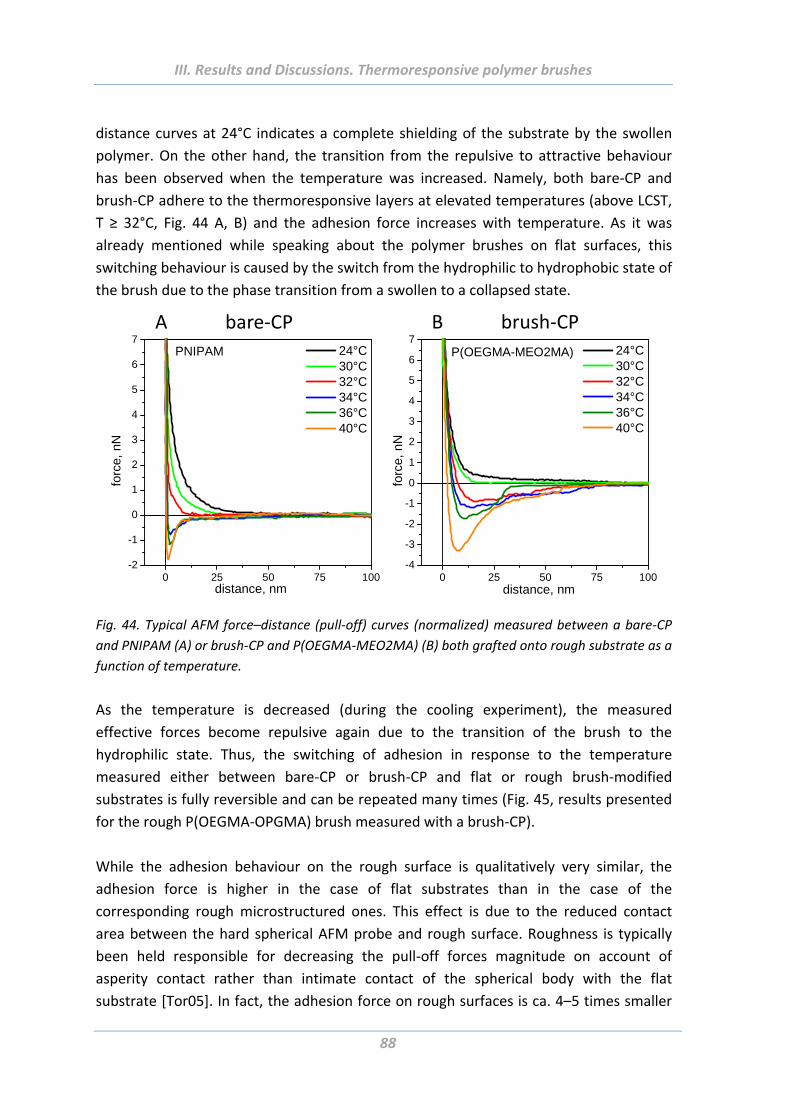
III. Results and Discussions. Thermoresponsive polymer brushes
88
distance curves at 24°C indicates a complete shielding of the substrate by the swollen
polymer. On the other hand, the transition from the repulsive to attractive behaviour
has been observed when the temperature was increased. Namely, both bare‐CP and
brush‐CP adhere to the thermoresponsive layers at elevated temperatures (above LCST,
T ≥ 32°C, Fig. 44 A, B) and the adhesion force increases with temperature. As it was
already mentioned while speaking about the polymer brushes on flat surfaces, this
switching behaviour is caused by the switch from the hydrophilic to hydrophobic state of
the brush due to the phase transition from a swollen to a collapsed state.
0 25 50 75 100-2
-1
0
1
2
3
4
5
6
7 24°C 30°C 32°C 34°C 36°C 40°C
forc
e, n
N
distance, nm
PNIPAM
A bare‐CP
0 25 50 75 100-4
-3
-2
-1
0
1
2
3
4
5
6
7 24°C 30°C 32°C 34°C 36°C 40°C
forc
e, n
N
distance, nm
P(OEGMA-MEO2MA)
B brush‐CP
Fig. 44. Typical AFM force–distance (pull‐off) curves (normalized) measured between a bare‐CP
and PNIPAM (A) or brush‐CP and P(OEGMA‐MEO2MA) (B) both grafted onto rough substrate as a
function of temperature.
As the temperature is decreased (during the cooling experiment), the measured
effective forces become repulsive again due to the transition of the brush to the
hydrophilic state. Thus, the switching of adhesion in response to the temperature
measured either between bare‐CP or brush‐CP and flat or rough brush‐modified
substrates is fully reversible and can be repeated many times (Fig. 45, results presented
for the rough P(OEGMA‐OPGMA) brush measured with a brush‐CP).
While the adhesion behaviour on the rough surface is qualitatively very similar, the
adhesion force is higher in the case of flat substrates than in the case of the
corresponding rough microstructured ones. This effect is due to the reduced contact
area between the hard spherical AFM probe and rough surface. Roughness is typically
been held responsible for decreasing the pull‐off forces magnitude on account of
asperity contact rather than intimate contact of the spherical body with the flat
substrate [Tor05]. In fact, the adhesion force on rough surfaces is ca. 4–5 times smaller
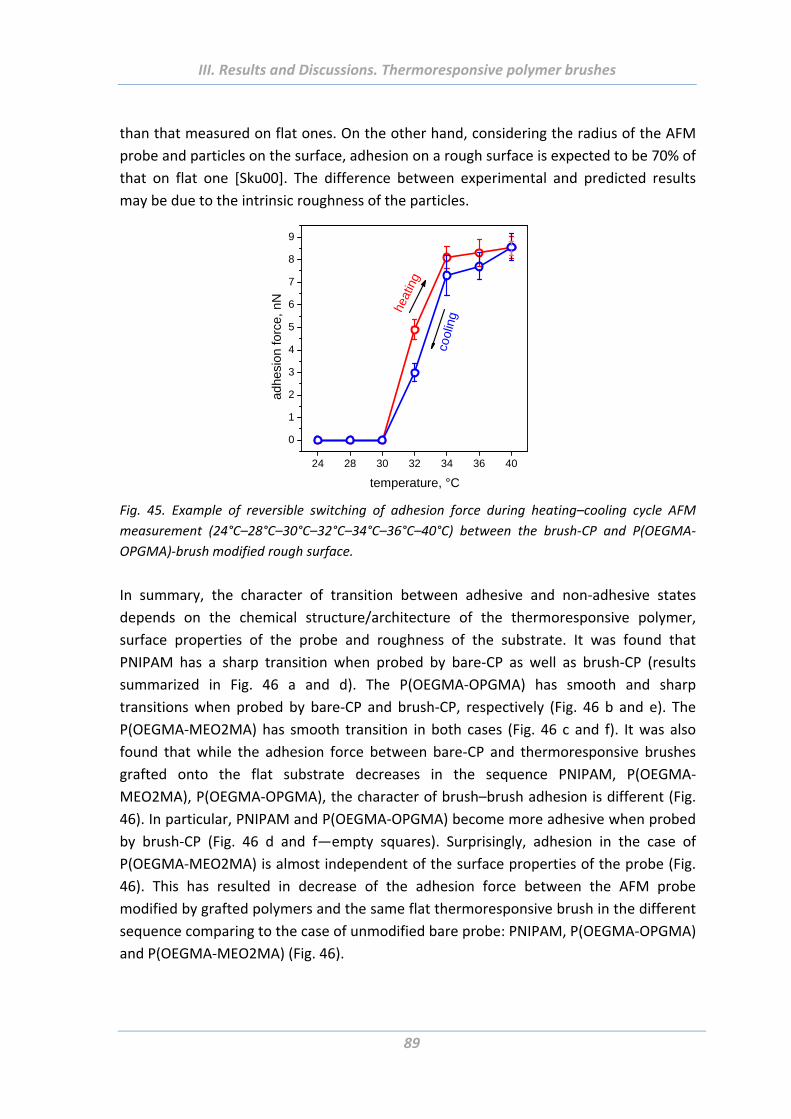
III. Results and Discussions. Thermoresponsive polymer brushes
89
than that measured on flat ones. On the other hand, considering the radius of the AFM
probe and particles on the surface, adhesion on a rough surface is expected to be 70% of
that on flat one [Sku00]. The difference between experimental and predicted results
may be due to the intrinsic roughness of the particles.
24 28 30 32 34 36 40
0
1
2
3
4
5
6
7
8
9
adhe
sion
for
ce,
nN
temperature, °C
cool
ing
heat
ing
Fig. 45. Example of reversible switching of adhesion force during heating–cooling cycle AFM
measurement (24°C–28°C–30°C–32°C–34°C–36°C–40°C) between the brush‐CP and P(OEGMA‐
OPGMA)‐brush modified rough surface.
In summary, the character of transition between adhesive and non‐adhesive states
depends on the chemical structure/architecture of the thermoresponsive polymer,
surface properties of the probe and roughness of the substrate. It was found that
PNIPAM has a sharp transition when probed by bare‐CP as well as brush‐CP (results
summarized in Fig. 46 a and d). The P(OEGMA‐OPGMA) has smooth and sharp
transitions when probed by bare‐CP and brush‐CP, respectively (Fig. 46 b and e). The
P(OEGMA‐MEO2MA) has smooth transition in both cases (Fig. 46 c and f). It was also
found that while the adhesion force between bare‐CP and thermoresponsive brushes
grafted onto the flat substrate decreases in the sequence PNIPAM, P(OEGMA‐
MEO2MA), P(OEGMA‐OPGMA), the character of brush–brush adhesion is different (Fig.
46). In particular, PNIPAM and P(OEGMA‐OPGMA) become more adhesive when probed
by brush‐CP (Fig. 46 d and f—empty squares). Surprisingly, adhesion in the case of
P(OEGMA‐MEO2MA) is almost independent of the surface properties of the probe (Fig.
46). This has resulted in decrease of the adhesion force between the AFM probe
modified by grafted polymers and the same flat thermoresponsive brush in the different
sequence comparing to the case of unmodified bare probe: PNIPAM, P(OEGMA‐OPGMA)
and P(OEGMA‐MEO2MA) (Fig. 46).
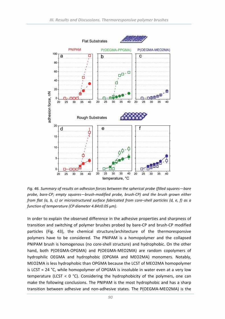
III. Results and Discussions. Thermoresponsive polymer brushes
90
Fig. 46. Summary of results on adhesion forces between the spherical probe (filled squares—bare
probe, bare‐CP; empty squares—brush‐modified probe, brush‐CP) and the brush grown either
from flat (a, b, c) or microstructured surface fabricated from core–shell particles (d, e, f) as a
function of temperature (CP diameter 4.84±0.05 µm).
In order to explain the observed difference in the adhesive properties and sharpness of
transition and switching of polymer brushes probed by bare‐CP and brush‐CP modified
particles (Fig. 43), the chemical structure/architecture of the thermoresponsive
polymers have to be considered. The PNIPAM is a homopolymer and the collapsed
PNIPAM brush is homogenous (no core‐shell structure) and hydrophobic. On the other
hand, both P(OEGMA‐OPGMA) and P(OEGMA‐MEO2MA) are random copolymers of
hydrophilic OEGMA and hydrophobic (OPGMA and MEO2MA) monomers. Notably,
MEO2MA is less hydrophobic than OPGMA because the LCST of MEO2MA homopolymer
is LCST = 24 °C, while homopolymer of OPGMA is insoluble in water even at a very low
temperature (LCST < 0 °C). Considering the hydrophobicity of the polymers, one can
make the following conclusions. The PNIPAM is the most hydrophobic and has a sharp
transition between adhesive and non‐adhesive states. The P(OEGMA‐MEO2MA) is the
III. Results and Discussions. Thermoresponsive polymer brushes
91
most hydrophilic system among three and has smooth transition between adhesive and
non‐adhesive states as well as weakest adhesive properties. The P(OEGMA‐OPGMA)
demonstrates an intermediate behaviour between PNIPAM and P(OEGMA‐MEO2MA)
and intermediate value of adhesion force obtained in the ‘‘symmetric’’ experiment with
brush‐CP.
1.6 Summary
The results of a comparative study on switchable adhesion of three kinds of
thermoresponsive polymer brushes grown on flat and rough substrates and having low
critical transition temperatures in biologically relevant region are presented and
discussed.
In many studies the thermoresponsive polymer brushes were shown to exhibit a
temperature‐dependent solution and surface behaviour [Lin99], [Nat03], [Gil04],
[Hyu04], [Sun04], Ala05, [Kes10], [Lee10]. The results coinciding with the previous reports were demonstrated in this thesis. Firstly, all synthesized thermoresponsive
brushes independently of their chemical structure and roughness of the supported
substrate are found to be completely non‐adhesive below LCST. On contrary, strong
attractive interactions were observed on these systems at temperatures above LCST
while probing with both hydrophobic (bare‐CP) and hydrophilic (brush‐CP) AFM tip.
Moreover, the adhesion forces show fully reversible character and can be repeated
many times.
The effect of tip radius and geometry on adhesion behaviour was investigated after that.
Three types of AFM probe (sharp tip (R = 5 nm), molten tip (R = 40 nm) and colloid probe
(R = 2420 nm)) were used for adhesion measurements. It was shown that the adhesive
force scales nonlinearly with probe radius and that the adhesion energy obtained using
Derjaguin‐Muller‐Toporov approaches decreases with the increase of tip radius. This is
in fact a contradiction to the theory but can be attributed to different depths of
penetration of probes in the polymer layers. The common is however the decrease of
adhesion in the sequence PNIPAM – P(OEGMA‐MEO2MA) – P(OEGMA‐OPGMA)
independently of the tip type. Based on the dynamic light scattering and cryo‐TEM
experiments, the latter effect is explained by the formation of a thin oligoethylene glycol
shell around the hydrophobic polymer core in P(OEGMA‐MEO2MA) system as well as in
P(OEGMA‐OPGMA) where the OEG layer is even more pronounced.
The adhesion force between the brush‐modified tip and the same flat thermoresponsive
brush decreases in the different sequence comparatively with the measurements with a
bar colloidal probe: PNIPAM, P(OEGMA‐OPGMA) and P(OEGMA‐MEO2MA). This
III. Results and Discussions. Thermoresponsive polymer brushes
92
difference in adhesion properties is explained by the specific chemical architecture of
polymers.
The samples are more adhesive on flat modified brush substrates than in the case of
corresponding microstructured ones. This effect is due to a reduced contact area
between the spherical probe and the rough surface.
The obtained findings could be useful for design of scaffolds for tissue engineering using
thermoresponsive particles which undergo sol–gel transition as well as for the
engineering of synthetic materials in interaction with biological objects.
As it was reported [Cun03], adhesion of cells to thermoresponsive surfaces is often
irreversible – cells do not adhere to swollen polymer film at low temperature while
becoming irreversibly adsorbed when the polymer layer collapses at an elevated
temperature. One of the possible origins of this effect could be too strong adhesion.
Therefore based on results presented in this work, it is expect that P(OEGMA‐OPGMA)
and P(OEGMA‐MEO2MA) systems, which demonstrates moderate sticky properties,
could be particularly promising to control adhesion of cells.
Although the PNIPAM is surely the most popular thermoresponsive polymer and can
therefore be considered as the gold standard [Lut08] in this research area, it has several
disadvantages which restrict its application for some biotechnology purposes. The
PNIPAM isn’t a bioinert polymer because of the presence of multiple amide functions in
its molecular structure which may lead to the formation of H‐bonding interactions with
amide groups of proteins [Bia04], [Wu05]. Thus, the thermoresponsive polymers based
on biocompatible oligo(ethylene glycol) side‐chains appear as promising alternative to
conventional PNIPAM for bioapplications and for design of thermoresponsive materials
[Lut08].
III. Results and Discussions. Solvent responsive and adaptive polymer brushes
93
2. Solvent responsive and adaptive polymer brushes
2.1 Abstract
This chapter is dealing with investigation of switchable and adaptable adhesion
properties of comb‐like random and block copolymer brushes made of PEG‐PDMS
biocompatible polymers grown from flat and rough substrates. Influence of chemical
composition, architecture of polymer chains, ratio of components, roughness of
substrate and state of surrounding media on adhesion forces was thoroughly
investigated. Surface segregation within the brush layer was investigated using XPS as
well as contact angle, zeta potential, null‐ellipsometry and adhesion measurements.
2.2 Introduction
Recent efforts were focused on design of responsive polymer brushes, which are either
biocompatible or both biocompatible and biodegradable [Wis08]. Poly(ethylene glycol)
(PEG) and poly(dimethylsiloxane) (PDMS) are synthetic biocompatible polymers. Both
polymers have low glass transition temperatures (Tg) and polymer chain segments are
mobile at room and at human body temperature. This mobility makes the systems as
though “alive”: they are able not just switch their properties from one state to another,
as it happens with polymers with high LCST (PNIPAM), adaptable systems are always on
the move and respond very sensitive to every small change in the surrounding media.
These peculiarities have opened great perspectives for the polymers to be used in
biomedical applications, for food and cosmetic industries [Wis08], [Kes10].
Polymer brushes consisted of two or more types of polymers can amplify their response
to external media due to combination of conformational changes and microphase
separation [Sid99], [Sog96].
Minko et al. have made non‐sticky surfaces in both, ambient and aqueous environment,
based on mixed PDMS‐PEO polymer brushes. The brushes are able quickly switch their
adhesion properties via reorganizing of its structure: in air PDMS chains occupy the top
of the layer, whereas in water it will be PEG. Such structures can be very useful as non‐
fouling coatings [She08].
The switching behaviour of hybrid polymer brushes made of PDMS and EPEI
(polyethylenimine) is based on the same principals [Mot07]. The system immediately
gain hydrophilic state in water and switch back to a hydrophobic state upon drying
[Mot07].
In this work more complex responsive/adaptive brushes formed by comb‐like PEG‐PDMS
random and block copolymers synthesised via ATRP have been studied.
III. Results and Discussions. Solvent responsive and adaptive polymer brushes
94
2.3 Experimental Part
2.3.1 Materials
Additionally to the chemicals used for the preparation of thermoresponsive polymers,
following chemicals were utilized for the fabrication of PEG‐PDMS systems: anisole
solution (purum, ≥99.0%, Fluka) and Tin(II) 2‐ethylhexanoate (~95%, Aldrich),
1H,1H,2H,2H‐Perfluorodecyltrichlorosilane (PFDTS, 97%, ABCR) were used as received.
Monomethacryloxypropyl terminated poly(dimethylsiloxane) (asymmetric, 6‐9 cSt,
Gelest) and oligo(ethylene glycol) methyl ether methacrylate (Mn = 475 g/mol, Aldrich)
were purified by passing through an Al2O3 column.
2.3.2 Modification of planar substrates
Highly polished single‐crystal silicon wafers (Semiconductor Processing Co.) were used as
a substrate also for PEG‐PDMS brushes. The wafers were modified through step
activation of hydroxyl‐groups, silanization and bromide initiator immobilization steps (all
details in Chapter III.1).
2.3.3 Growing of polymer brushes from flat and rough surfaces
Three kinds of comb‐like PEG‐PDMS layers were synthesized: two block copolymer ones
where either PEG or PDMS are grafted first and one random copolymer where both
macromonomers are grafted simultaneously and randomly. Different ratios of
components for each of the three types of brushes were used: 20%vol PEG + 80%vol
PDMS, 50%vol PEG + 50%vol PDMS, 80%vol PEG + 20%vol PDMS. Homopolymer brushes
PEG and PDMS were prepared as well. The chemical structures of PEG and PDMS and
schematic structures of PEG‐PDMS‐based copolymers are presented in Fig. 47.
Two sets of brushes with different thicknesses – around 15 and 40 nm – were prepared.
The thickness of polymer layers on the wafers in the dry state was measured using a
null‐ellipsometer.
The grafting density calculated based on the results of GPC (typical molecular weight of
brushes with thickness H = 15 nm and H = 40 nm is Mn = 20 kg/mol and Mn = 60 kg/mol,
respectively; PDI = 1.7 – 2.5) and ellipsometry was ca Γ = 0.4 chain/nm2, while the
distance between grating points was around D = 2 nm. The radius of gyration (Rg) of the
used polymers is unknown but expected to be more than 5 nm. For example Rg of
polystyrene with a molecular weight of about 30000 g/mol in a good solvent (toluene) is
10 nm [Siq95]. Since the distance between grafting points is smaller than the thickness
of the polymer layers, the polymer‐grafted layers can be considered as a brush‐like in
both the dry and swollen states [Min06].
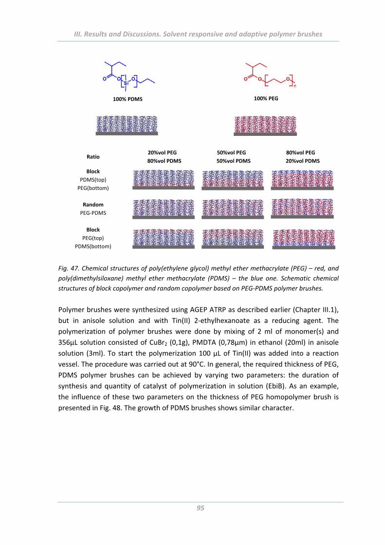
III. Results and Discussions. Solvent responsive and adaptive polymer brushes
95
100% PDMS
100% PEG
Ratio 20%vol PEG
80%vol PDMS
50%vol PEG
50%vol PDMS
80%vol PEG
20%vol PDMS
Block
PDMS(top)
PEG(bottom)
Random
PEG‐PDMS
Block
PEG(top)
PDMS(bottom)
Fig. 47. Chemical structures of poly(ethylene glycol) methyl ether methacrylate (PEG) – red, and
poly(dimethylsiloxane) methyl ether methacrylate (PDMS) – the blue one. Schematic chemical
structures of block copolymer and random copolymer based on PEG‐PDMS polymer brushes.
Polymer brushes were synthesized using AGEP ATRP as described earlier (Chapter III.1),
but in anisole solution and with Tin(II) 2‐ethylhexanoate as a reducing agent. The
polymerization of polymer brushes were done by mixing of 2 ml of monomer(s) and
356µL solution consisted of CuBr2 (0,1g), PMDTA (0,78µm) in ethanol (20ml) in anisole
solution (3ml). To start the polymerization 100 µL of Tin(II) was added into a reaction
vessel. The procedure was carried out at 90°C. In general, the required thickness of PEG,
PDMS polymer brushes can be achieved by varying two parameters: the duration of
synthesis and quantity of catalyst of polymerization in solution (EbiB). As an example,
the influence of these two parameters on the thickness of PEG homopolymer brush is
presented in Fig. 48. The growth of PDMS brushes shows similar character.
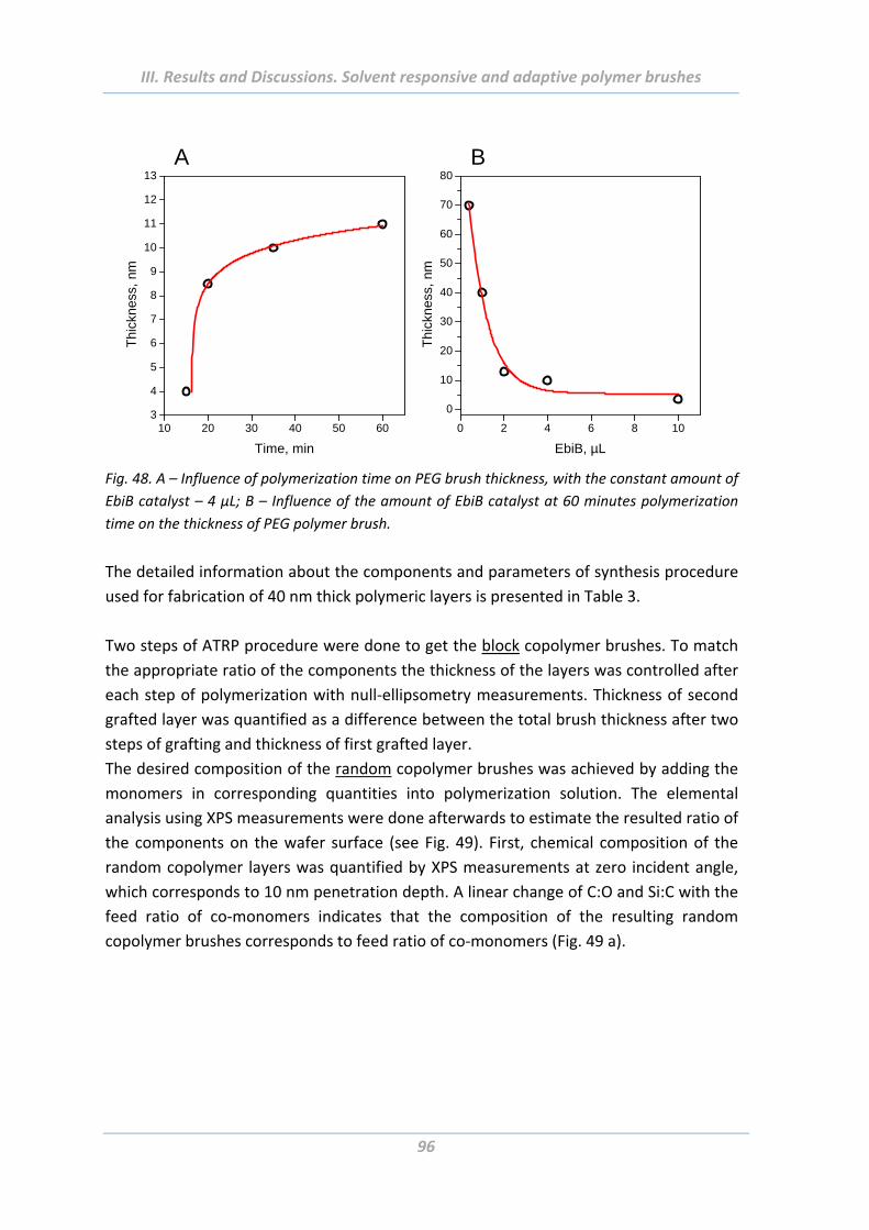
III. Results and Discussions. Solvent responsive and adaptive polymer brushes
96
0 2 4 6 8 10
0
10
20
30
40
50
60
70
80
Thi
ckn
ess,
nm
EbiB, µL
10 20 30 40 50 603
4
5
6
7
8
9
10
11
12
13
Thi
ckn
ess,
nm
Time, min
A B
Fig. 48. A – Influence of polymerization time on PEG brush thickness, with the constant amount of
EbiB catalyst – 4 µL; B – Influence of the amount of EbiB catalyst at 60 minutes polymerization
time on the thickness of PEG polymer brush.
The detailed information about the components and parameters of synthesis procedure
used for fabrication of 40 nm thick polymeric layers is presented in Table 3.
Two steps of ATRP procedure were done to get the block copolymer brushes. To match
the appropriate ratio of the components the thickness of the layers was controlled after
each step of polymerization with null‐ellipsometry measurements. Thickness of second
grafted layer was quantified as a difference between the total brush thickness after two
steps of grafting and thickness of first grafted layer.
The desired composition of the random copolymer brushes was achieved by adding the
monomers in corresponding quantities into polymerization solution. The elemental
analysis using XPS measurements were done afterwards to estimate the resulted ratio of
the components on the wafer surface (see Fig. 49). First, chemical composition of the
random copolymer layers was quantified by XPS measurements at zero incident angle,
which corresponds to 10 nm penetration depth. A linear change of C:O and Si:C with the
feed ratio of co‐monomers indicates that the composition of the resulting random
copolymer brushes corresponds to feed ratio of co‐monomers (Fig. 49 a).
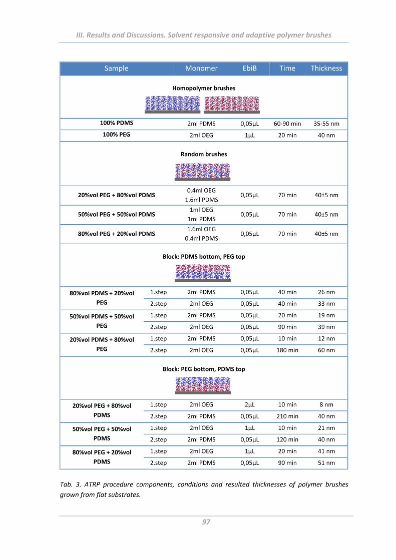
III. Results and Discussions. Solvent responsive and adaptive polymer brushes
97
Sample Monomer EbiB Time Thickness
Homopolymer brushes
100% PDMS 2ml PDMS 0,05µL 60‐90 min 35‐55 nm
100% PEG 2ml OEG 1µL 20 min 40 nm
Random brushes
20%vol PEG + 80%vol PDMS 0.4ml OEG
1.6ml PDMS 0,05µL 70 min 40±5 nm
50%vol PEG + 50%vol PDMS 1ml OEG
1ml PDMS 0,05µL 70 min 40±5 nm
80%vol PEG + 20%vol PDMS 1.6ml OEG
0.4ml PDMS 0,05µL 70 min 40±5 nm
Block: PDMS bottom, PEG top
80%vol PDMS + 20%vol
PEG
1.step 2ml PDMS 0,05µL 40 min 26 nm
2.step 2ml OEG 0,05µL 40 min 33 nm
50%vol PDMS + 50%vol
PEG
1.step 2ml PDMS 0,05µL 20 min 19 nm
2.step 2ml OEG 0,05µL 90 min 39 nm
20%vol PDMS + 80%vol
PEG
1.step 2ml PDMS 0,05µL 10 min 12 nm
2.step 2ml OEG 0,05µL 180 min 60 nm
Block: PEG bottom, PDMS top
20%vol PEG + 80%vol
PDMS
1.step 2ml OEG 2µL 10 min 8 nm
2.step 2ml PDMS 0,05µL 210 min 40 nm
50%vol PEG + 50%vol
PDMS
1.step 2ml OEG 1µL 10 min 21 nm
2.step 2ml PDMS 0,05µL 120 min 40 nm
80%vol PEG + 20%vol
PDMS
1.step 2ml OEG 1µL 20 min 41 nm
2.step 2ml PDMS 0,05µL 90 min 51 nm
Tab. 3. ATRP procedure components, conditions and resulted thicknesses of polymer brushes
grown from flat substrates.
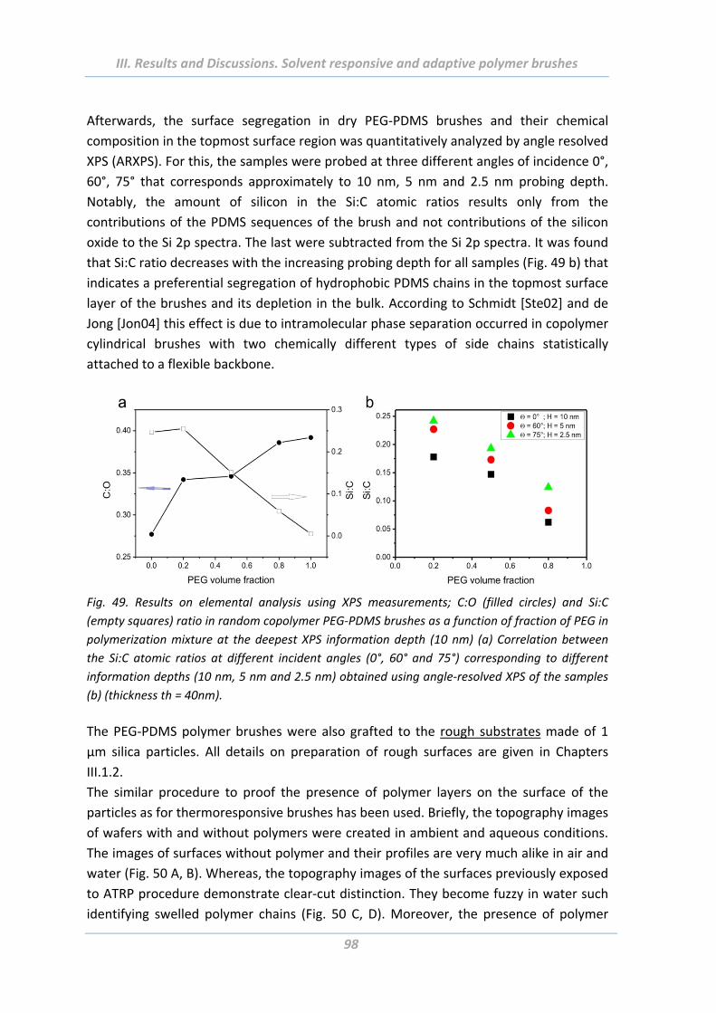
III. Results and Discussions. Solvent responsive and adaptive polymer brushes
98
Afterwards, the surface segregation in dry PEG‐PDMS brushes and their chemical
composition in the topmost surface region was quantitatively analyzed by angle resolved
XPS (ARXPS). For this, the samples were probed at three different angles of incidence 0°,
60°, 75° that corresponds approximately to 10 nm, 5 nm and 2.5 nm probing depth.
Notably, the amount of silicon in the Si:C atomic ratios results only from the
contributions of the PDMS sequences of the brush and not contributions of the silicon
oxide to the Si 2p spectra. The last were subtracted from the Si 2p spectra. It was found
that Si:C ratio decreases with the increasing probing depth for all samples (Fig. 49 b) that
indicates a preferential segregation of hydrophobic PDMS chains in the topmost surface
layer of the brushes and its depletion in the bulk. According to Schmidt [Ste02] and de
Jong [Jon04] this effect is due to intramolecular phase separation occurred in copolymer
cylindrical brushes with two chemically different types of side chains statistically
attached to a flexible backbone.
Fig. 49. Results on elemental analysis using XPS measurements; C:O (filled circles) and Si:C
(empty squares) ratio in random copolymer PEG‐PDMS brushes as a function of fraction of PEG in
polymerization mixture at the deepest XPS information depth (10 nm) (a) Correlation between
the Si:C atomic ratios at different incident angles (0°, 60° and 75°) corresponding to different
information depths (10 nm, 5 nm and 2.5 nm) obtained using angle‐resolved XPS of the samples
(b) (thickness th = 40nm).
The PEG‐PDMS polymer brushes were also grafted to the rough substrates made of 1
µm silica particles. All details on preparation of rough surfaces are given in Chapters
III.1.2.
The similar procedure to proof the presence of polymer layers on the surface of the
particles as for thermoresponsive brushes has been used. Briefly, the topography images
of wafers with and without polymers were created in ambient and aqueous conditions.
The images of surfaces without polymer and their profiles are very much alike in air and
water (Fig. 50 A, B). Whereas, the topography images of the surfaces previously exposed
to ATRP procedure demonstrate clear‐cut distinction. They become fuzzy in water such
identifying swelled polymer chains (Fig. 50 C, D). Moreover, the presence of polymer
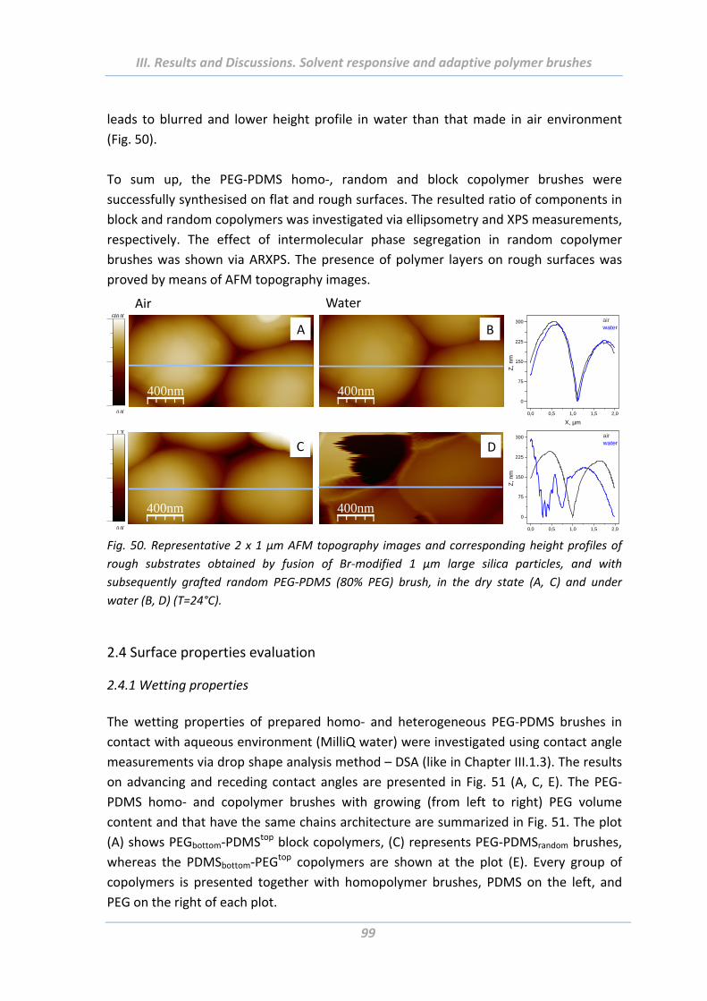
III. Results and Discussions. Solvent responsive and adaptive polymer brushes
99
leads to blurred and lower height profile in water than that made in air environment
(Fig. 50).
To sum up, the PEG‐PDMS homo‐, random and block copolymer brushes were
successfully synthesised on flat and rough surfaces. The resulted ratio of components in
block and random copolymers was investigated via ellipsometry and XPS measurements,
respectively. The effect of intermolecular phase segregation in random copolymer
brushes was shown via ARXPS. The presence of polymer layers on rough surfaces was
proved by means of AFM topography images.
400nm 400nm
400nm 400nm
600 00
0 00 0,0 0,5 1,0 1,5 2,0
0
75
150
225
300
Z, n
m
X, µm
airwater
0,0 0,5 1,0 1,5 2,0
0
75
150
225
300
Z, n
m
airwater
1 20
0 00
A B
C D
Air Water
Fig. 50. Representative 2 x 1 µm AFM topography images and corresponding height profiles of
rough substrates obtained by fusion of Br‐modified 1 µm large silica particles, and with
subsequently grafted random PEG‐PDMS (80% PEG) brush, in the dry state (A, C) and under
water (B, D) (T=24°C).
2.4 Surface properties evaluation
2.4.1 Wetting properties
The wetting properties of prepared homo‐ and heterogeneous PEG‐PDMS brushes in
contact with aqueous environment (MilliQ water) were investigated using contact angle
measurements via drop shape analysis method – DSA (like in Chapter III.1.3). The results
on advancing and receding contact angles are presented in Fig. 51 (A, C, E). The PEG‐
PDMS homo‐ and copolymer brushes with growing (from left to right) PEG volume
content and that have the same chains architecture are summarized in Fig. 51. The plot
(A) shows PEGbottom‐PDMStop block copolymers, (C) represents PEG‐PDMSrandom brushes,
whereas the PDMSbottom‐PEGtop copolymers are shown at the plot (E). Every group of
copolymers is presented together with homopolymer brushes, PDMS on the left, and
PEG on the right of each plot.
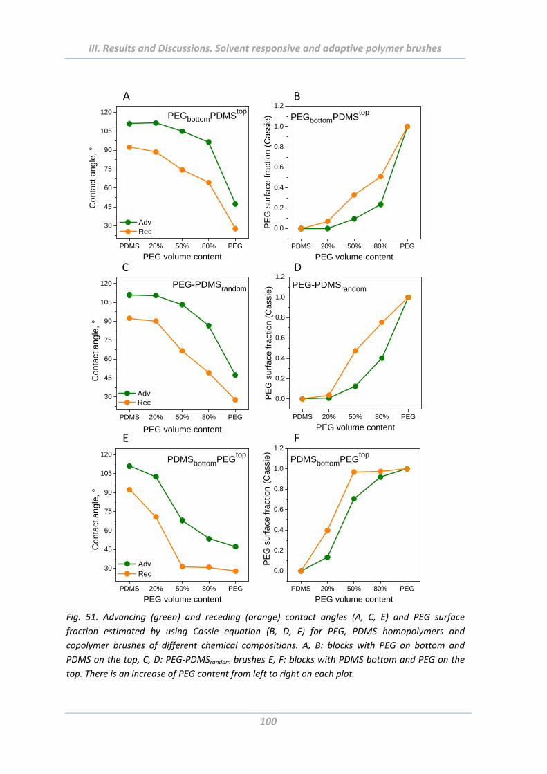
III. Results and Discussions. Solvent responsive and adaptive polymer brushes
100
PDMS 20% 50% 80% PEG
30
45
60
75
90
105
120
Co
ntac
t an
gle
, °
PEG volume content
Adv Rec
PEGbottomPDMStop
A
PDMS 20% 50% 80% PEG
30
45
60
75
90
105
120
Con
tact
ang
le,
°
PEG-PDMSrandom
PEG volume content
Adv Rec
C
PDMS 20% 50% 80% PEG
30
45
60
75
90
105
120
C
on
tact
an
gle
, °
PDMSbottomPEGtop
PEG volume content
Adv Rec
E
PDMS 20% 50% 80% PEG
0.0
0.2
0.4
0.6
0.8
1.0
1.2
PEGbottomPDMStop
PE
G s
urf
ace
fra
ctio
n (
Ca
ssie
)PEG volume content
PDMS 20% 50% 80% PEG
0.0
0.2
0.4
0.6
0.8
1.0
1.2PEG-PDMSrandom
PE
G s
urf
ace
frac
tion
(Cas
sie)
PEG volume content
PDMS 20% 50% 80% PEG
0.0
0.2
0.4
0.6
0.8
1.0
1.2
PDMSbottomPEGtop
PE
G s
urf
ace
fra
ctio
n (
Cas
sie
)
PEG volume content
D
F
B
Fig. 51. Advancing (green) and receding (orange) contact angles (A, C, E) and PEG surface
fraction estimated by using Cassie equation (B, D, F) for PEG, PDMS homopolymers and
copolymer brushes of different chemical compositions. A, B: blocks with PEG on bottom and
PDMS on the top, C, D: PEG‐PDMSrandom brushes E, F: blocks with PDMS bottom and PEG on the
top. There is an increase of PEG content from left to right on each plot.
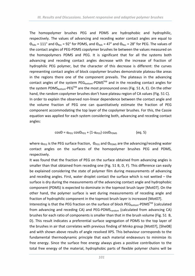
III. Results and Discussions. Solvent responsive and adaptive polymer brushes
101
The homopolymer brushes PEG and PDMS are hydrophobic and hydrophilic,
respectively. The values of advancing and receding water contact angles are equal to
ΘAdv = 111° and ΘRec = 92° for PDMS, and ΘAdv = 47° and ΘRec = 28° for PEG. The values of
the contact angles of PEG‐PDMS copolymer brushes lie between the values measured on
the homopolymers PDMS and PEG. It is significant that for all the systems both
advancing and receding contact angles decrease with the increase of fraction of
hydrophilic PEG polymer, but the character of this decrease is different: the curves
representing contact angles of block copolymer brushes demonstrate plateau‐like areas
in the regions there one of the component prevails. The plateaus in the advancing
contact angles of the system PEGbottom‐PDMStop and in the receding contact angles for
the system PDMSbottom‐PEGtop are the most pronounced ones (Fig. 51 A, E). On the other
hand, the random copolymer brushes don’t have plateau region of CA values (Fig. 51 C).
In order to explain the observed non‐linear dependence between the contact angle and
the volume fraction of PEG one can quantitatively estimate the fraction of PEG
component accommodating the top layer of the copolymer brushes. For this, the Cassie
equation was applied for each system considering both, advancing and receding contact
angles:
cosΘ = αPEG cosΘPEG + (1‐αPEG) cosΘPDMS (eq. 5)
where αPEG is the PEG surface fraction, ΘPEG and ΘPDMS are the advancing/receding water
contact angles on the surfaces of the homopolymer brushes PEG and PDMS,
respectively.
It was found that the fraction of PEG on the surface obtained from advancing angles is
smaller than that obtained from receding one (Fig. 51 B, D, F). This difference can easily
be explained considering the state of polymer film during measurements of advancing
and receding angles. First, water droplet contact the surface which is not wetted – the
surface is dry during the measurements of the advancing contact angle and hydrophobic
component (PDMS) is expected to dominate in the topmost brush layer [Mot07]. On the
other hand, the polymer surface is wet during measurements of receding angle and
fraction of hydrophilic component in the topmost brush layer is increased [Mot07].
Interesting is that the PEG fraction on the surface of block PEGbottom‐PDMStop (calculated
from advancing and receding CA) and PEG‐PDMSrandom (calculated from advancing CA)
brushes for each ratio of components is smaller than that in the brush volume (Fig. 51 B,
D). This result indicates a preferential surface segregation of PDMS to the top layer of
the brushes in air that correlates with previous finding of Minko group [Mot07], [She08]
and with shown above results of angle resolved XPS. This behaviour corresponds to the
fundamental thermodynamic principle that each material endeavours to minimize its
free energy. Since the surface free energy always gives a positive contribution to the
total free energy of the material, hydrophobic parts of flexible polymer chains will be
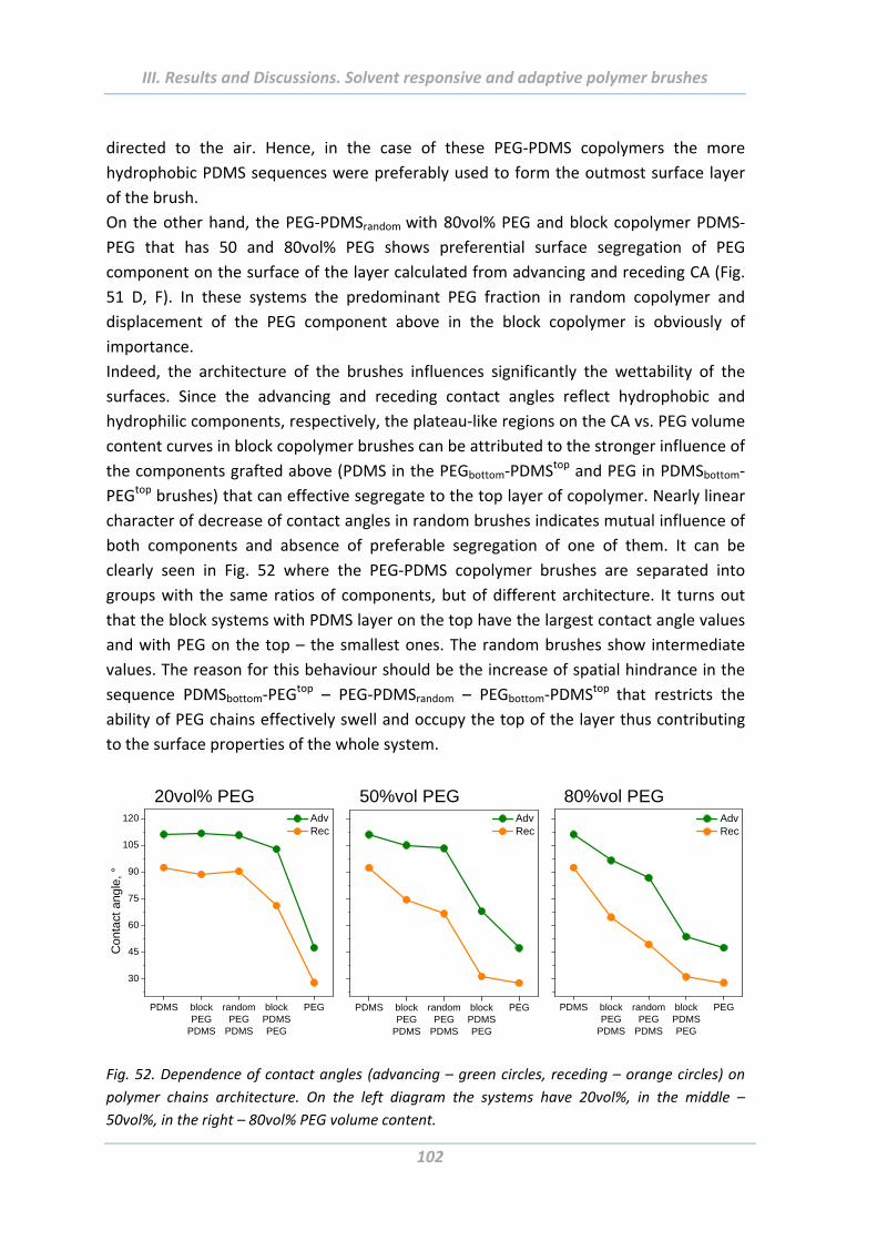
III. Results and Discussions. Solvent responsive and adaptive polymer brushes
102
directed to the air. Hence, in the case of these PEG‐PDMS copolymers the more
hydrophobic PDMS sequences were preferably used to form the outmost surface layer
of the brush.
On the other hand, the PEG‐PDMSrandom with 80vol% PEG and block copolymer PDMS‐
PEG that has 50 and 80vol% PEG shows preferential surface segregation of PEG
component on the surface of the layer calculated from advancing and receding CA (Fig.
51 D, F). In these systems the predominant PEG fraction in random copolymer and
displacement of the PEG component above in the block copolymer is obviously of
importance.
Indeed, the architecture of the brushes influences significantly the wettability of the
surfaces. Since the advancing and receding contact angles reflect hydrophobic and
hydrophilic components, respectively, the plateau‐like regions on the CA vs. PEG volume
content curves in block copolymer brushes can be attributed to the stronger influence of
the components grafted above (PDMS in the PEGbottom‐PDMStop and PEG in PDMSbottom‐
PEGtop brushes) that can effective segregate to the top layer of copolymer. Nearly linear
character of decrease of contact angles in random brushes indicates mutual influence of
both components and absence of preferable segregation of one of them. It can be
clearly seen in Fig. 52 where the PEG‐PDMS copolymer brushes are separated into
groups with the same ratios of components, but of different architecture. It turns out
that the block systems with PDMS layer on the top have the largest contact angle values
and with PEG on the top – the smallest ones. The random brushes show intermediate
values. The reason for this behaviour should be the increase of spatial hindrance in the
sequence PDMSbottom‐PEGtop – PEG‐PDMSrandom – PEGbottom‐PDMStop that restricts the
ability of PEG chains effectively swell and occupy the top of the layer thus contributing
to the surface properties of the whole system.
PDMS blockPEG
PDMS
randomPEG
PDMS
blockPDMSPEG
PEG
30
45
60
75
90
105
120 Adv Rec
Con
tact
ang
le, °
20vol% PEG
PDMS blockPEG
PDMS
randomPEG
PDMS
blockPDMSPEG
PEG
Adv Rec
50%vol PEG
PDMS blockPEG
PDMS
randomPEG
PDMS
blockPDMSPEG
PEG
Adv Rec
80%vol PEG
Fig. 52. Dependence of contact angles (advancing – green circles, receding – orange circles) on
polymer chains architecture. On the left diagram the systems have 20vol%, in the middle –
50vol%, in the right – 80vol% PEG volume content.
III. Results and Discussions. Solvent responsive and adaptive polymer brushes
103
2.4.2 Swelling properties
The swelling properties of PEG, PDMS homo‐, block and random copolymer brushes
were investigated using null‐ellipsometry. All measurements were performed at room
temperature. The maximal layer thickness achieved under water was compared with the
thickness in a dry state. The correlation between these two values is called swelling
degree of the corresponding polymer brush.
It was found that surface with grafted pure PDMS almost do not swell in water and the
systems with 20vol% of PEG swell slightly (Fig. 53). Further, considerable increase of
swelling degree with growing PEG content was detected. This tendency is observed on
all PEG‐PDMS copolymer brushes independently of their architecture and can be
explained by increasing content of hydrophilic PEG that swells well in water. The
homopolymer PEG achieves the maximal degree of swelling that is equal to 3.
PDMS 20% 50% 80% PEG
1.0
1.5
2.0
2.5
3.0
PEG volume content
Sw
ellin
g d
egre
e
PEGbottomPDMStop
PDMS 20% 50% 80% PEG
1.0
1.5
2.0
2.5
3.0
PEG volume content
PDMSbottomPEGtop
PDMS 20% 50% 80% PEG
1.0
1.5
2.0
2.5
3.0
PEG volume content
PEG-PDMSrandom
A B C
Fig. 53. Swelling behaviour in water of PEG, PDMS homo‐ and copolymer brushes with different
chemical compositions. A: blocks with PEG on bottom and PDMS on the top, C: blocks with
inverse sequence of components, B: PEG‐PDMSrandom brushes. There is an increase of PEG content
from left to right on each plot.
It is worth notice that like if was found for the measurements of CA the block copolymer
brushes demonstrate plateau behaviour of their swelling performance (plots A and C in
Fig. 53), whereas the random systems have nearly linear dependence on PEG volume
content (plot B). This should be because of the already mentioned spatial hindrances
that restrict swelling and rearrangement of the hydrophilic PEG.
In the Fig. 54 the results on swelling (blue curves) and wetting (black curves) behaviour
of PEG‐PDMS copolymer brushes dependent on their chain architecture are
summarized. Interesting is the mirror tendencies of contact angles and swelling degrees
measured on systems with 20vol% PEG. There is a clear plateau character for both
parameters because of the prevalence of PDMS component and its preferable
segregation on the top of the brush. Almost no influence of chains architecture was
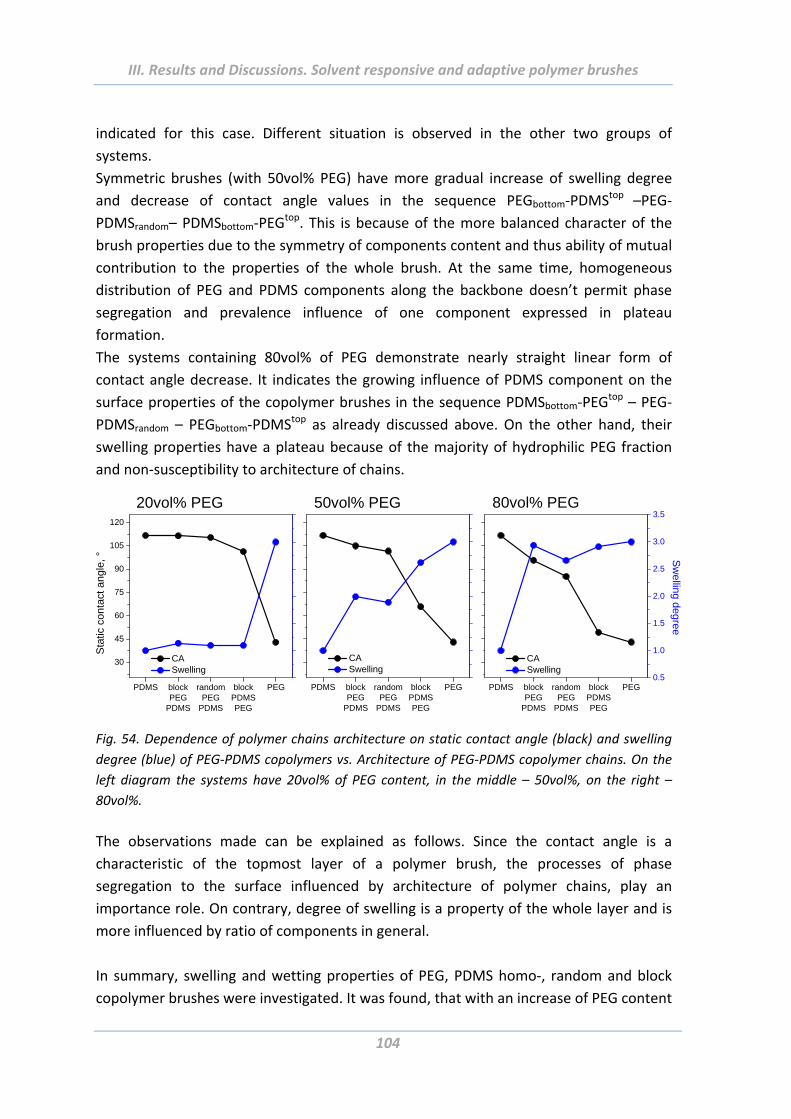
III. Results and Discussions. Solvent responsive and adaptive polymer brushes
104
indicated for this case. Different situation is observed in the other two groups of
systems.
Symmetric brushes (with 50vol% PEG) have more gradual increase of swelling degree
and decrease of contact angle values in the sequence PEGbottom‐PDMStop –PEG‐
PDMSrandom– PDMSbottom‐PEGtop. This is because of the more balanced character of the
brush properties due to the symmetry of components content and thus ability of mutual
contribution to the properties of the whole brush. At the same time, homogeneous
distribution of PEG and PDMS components along the backbone doesn’t permit phase
segregation and prevalence influence of one component expressed in plateau
formation.
The systems containing 80vol% of PEG demonstrate nearly straight linear form of
contact angle decrease. It indicates the growing influence of PDMS component on the
surface properties of the copolymer brushes in the sequence PDMSbottom‐PEGtop – PEG‐
PDMSrandom – PEGbottom‐PDMStop as already discussed above. On the other hand, their
swelling properties have a plateau because of the majority of hydrophilic PEG fraction
and non‐susceptibility to architecture of chains.
PDMS blockPEG
PDMS
randomPEG
PDMS
blockPDMSPEG
PEG
30
45
60
75
90
105
120
CA Swelling
Sta
tic c
onta
ct a
ngle
, °
PDMS blockPEG
PDMS
randomPEG
PDMS
blockPDMSPEG
PEG
CA Swelling
PDMS blockPEG
PDMS
randomPEG
PDMS
blockPDMSPEG
PEG
Sw
elling degree
CA Swelling
0.5
1.0
1.5
2.0
2.5
3.0
3.520vol% PEG 50vol% PEG 80vol% PEG
Fig. 54. Dependence of polymer chains architecture on static contact angle (black) and swelling
degree (blue) of PEG‐PDMS copolymers vs. Architecture of PEG‐PDMS copolymer chains. On the
left diagram the systems have 20vol% of PEG content, in the middle – 50vol%, on the right –
80vol%.
The observations made can be explained as follows. Since the contact angle is a
characteristic of the topmost layer of a polymer brush, the processes of phase
segregation to the surface influenced by architecture of polymer chains, play an
importance role. On contrary, degree of swelling is a property of the whole layer and is
more influenced by ratio of components in general.
In summary, swelling and wetting properties of PEG, PDMS homo‐, random and block
copolymer brushes were investigated. It was found, that with an increase of PEG content
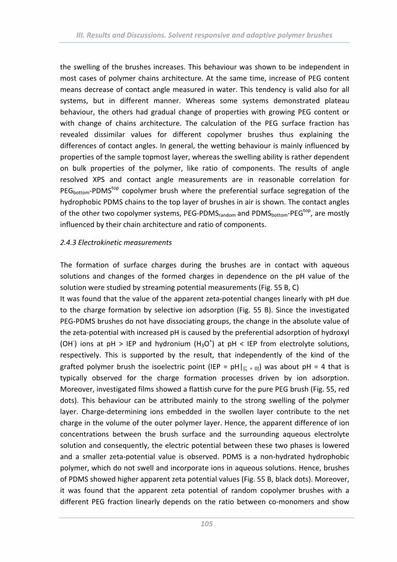
III. Results and Discussions. Solvent responsive and adaptive polymer brushes
105
the swelling of the brushes increases. This behaviour was shown to be independent in
most cases of polymer chains architecture. At the same time, increase of PEG content
means decrease of contact angle measured in water. This tendency is valid also for all
systems, but in different manner. Whereas some systems demonstrated plateau
behaviour, the others had gradual change of properties with growing PEG content or
with change of chains architecture. The calculation of the PEG surface fraction has
revealed dissimilar values for different copolymer brushes thus explaining the
differences of contact angles. In general, the wetting behaviour is mainly influenced by
properties of the sample topmost layer, whereas the swelling ability is rather dependent
on bulk properties of the polymer, like ratio of components. The results of angle
resolved XPS and contact angle measurements are in reasonable correlation for
PEGbottom‐PDMStop copolymer brush where the preferential surface segregation of the
hydrophobic PDMS chains to the top layer of brushes in air is shown. The contact angles
of the other two copolymer systems, PEG‐PDMSrandom and PDMSbottom‐PEGtop, are mostly
influenced by their chain architecture and ratio of components.
2.4.3 Electrokinetic measurements
The formation of surface charges during the brushes are in contact with aqueous
solutions and changes of the formed charges in dependence on the pH value of the
solution were studied by streaming potential measurements (Fig. 55 B, C)
It was found that the value of the apparent zeta‐potential changes linearly with pH due
to the charge formation by selective ion adsorption (Fig. 55 B). Since the investigated
PEG‐PDMS brushes do not have dissociating groups, the change in the absolute value of
the zeta‐potential with increased pH is caused by the preferential adsorption of hydroxyl
(OH‐) ions at pH > IEP and hydronium (H3O+) at pH < IEP from electrolyte solutions,
respectively. This is supported by the result, that independently of the kind of the
grafted polymer brush the isoelectric point (IEP = pH|[ = 0]) was about pH = 4 that is
typically observed for the charge formation processes driven by ion adsorption.
Moreover, investigated films showed a flattish curve for the pure PEG brush (Fig. 55, red
dots). This behaviour can be attributed mainly to the strong swelling of the polymer
layer. Charge‐determining ions embedded in the swollen layer contribute to the net
charge in the volume of the outer polymer layer. Hence, the apparent difference of ion
concentrations between the brush surface and the surrounding aqueous electrolyte
solution and consequently, the electric potential between these two phases is lowered
and a smaller zeta‐potential value is observed. PDMS is a non‐hydrated hydrophobic
polymer, which do not swell and incorporate ions in aqueous solutions. Hence, brushes
of PDMS showed higher apparent zeta potential values (Fig. 55 B, black dots). Moreover,
it was found that the apparent zeta potential of random copolymer brushes with a
different PEG fraction linearly depends on the ratio between co‐monomers and show

III. Results and Discussions. Solvent responsive and adaptive polymer brushes
106
intermediate trends between mono component PEG and PDMS (Fig. 55 C). In fact, since
PEG swells strongly in water, one can expect that values of apparent zeta potential of
the brushes must be close to that of pure PEG layer. The observed linear change of zeta‐
potential (Fig. 55 C) with an increase volume fraction of PEG in brush could be explained
by the resolution of streaming potential method. In fact, the deeper sink into the flexible
brush layer “open” structure could be expected during the streaming of electrolyte
solution and, therefore, not necessary very topmost layer is measured. For instance,
Duval et al. [Duv11] discussed so‐called open structures at soft multilayered
polyelectrolyte films illustrated by streaming current measurements.
Furthermore, the overall tendencies in the changes of contact angle, swelling ratio and
zeta‐potential values with the brush composition are in good agreement. The lower
value of PDMS content in the system corresponds to the lower value of
advancing/receding contact angles, lower swelling property as well as lower value of
apparent zeta‐potential (Fig. 51 C, 55 A, C).
PDMS 20% 50% 80% PEG
1.0
1.5
2.0
2.5
3.0
PEG volume content
Sw
ellin
g de
gre
e
A B
PDMS 20% 50% 80% PEG
-50
-40
-30
-20
-10
App
aren
t zet
a-po
tent
ial,
mV
(pH
=10
)
PEG volume content
C
Fig. 55. Apparent zeta‐potential vs. pH (measured in 10‐3M KCl) for PEG, PDMS mono and
random copolymer brushes with different chemical compositions.
2.4.4 Surface morphology
Next, the surface morphology of homo‐ and copolymer brushes was investigated in
water and in air. The measurements were performed on Dimension V AFM (Veeco
Instruments, Inc., USA) in TappingMode both in dry and aqueous media (with a Fluid Tip
Folder) with silicon TappingMode tip (resonant frequency 200‐400kHz) and ultrasharp
silicon tip CSC11 (resonant frequency 20‐40 kHz) (MikroMasch, Estonia), respectively.
The surface morphology of homopolymer brushes is, as expected, smooth and
featureless independently of the solvent (Fig. 56).
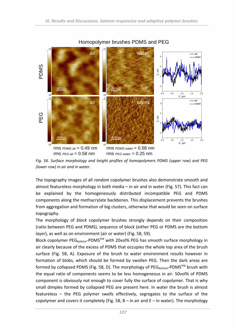
III. Results and Discussions. Solvent responsive and adaptive polymer brushes
107
0.0 0.5 1.0 1.5 2.0
0
1
2
3 air water
Z,
nm
X, µm
400nm
water
PE
G
400nm
air
400nm
water
0.0 0.5 1.0 1.5 2.0
0
1
2
3 air water
Z, n
m
X, µm
400nm
air
PD
MS
4.00
0.00
6.00
0.003.50
0.00
3.00
0.00rms PDMS air = 0.49 nmrms PEG air = 0.58 nm
rms PDMS water = 0.58 nmrms PEG water = 0.25 nm
Homopolymer brushes PDMS and PEG
Fig. 56. Surface morphology and height profiles of homopolymers PDMS (upper row) and PEG
(lower row) in air and in water.
The topography images of all random copolymer brushes also demonstrate smooth and
almost featureless morphology in both media – in air and in water (Fig. 57). This fact can
be explained by the homogeneously distributed incompatible PEG and PDMS
components along the methacrylate backbones. This displacement prevents the brushes
from aggregation and formation of big clusters, otherwise that would be seen on surface
topography.
The morphology of block copolymer brushes strongly depends on their composition
(ratio between PEG and PDMS), sequence of block (either PEG or PDMS are the bottom
layer), as well as on environment (air or water) (Fig. 58, 59).
Block copolymer PEGbottom‐PDMStop with 20vol% PEG has smooth surface morphology in
air clearly because of the excess of PDMS that occupies the whole top area of the brush
surface (Fig. 58, A). Exposure of the brush to water environment results however in
formation of blobs, which should be formed by swollen PEG. Then the dark areas are
formed by collapsed PDMS (Fig. 58, D). The morphology of PEGbottom‐PDMStop brush with
the equal ratio of components seems to be less homogeneous in air. 50vol% of PDMS
component is obviously not enough to cover fully the surface of copolymer. That is why
small dimples formed by collapsed PEG are present here. In water the brush is almost
featureless – the PEG polymer swells effectively, segregates to the surface of the
copolymer and covers it completely (Fig. 58, B – in air and E – in water). The morphology
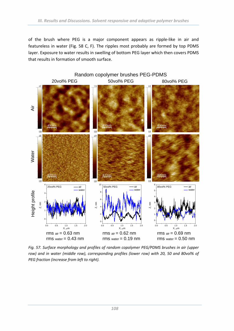
III. Results and Discussions. Solvent responsive and adaptive polymer brushes
108
of the brush where PEG is a major component appears as ripple‐like in air and
featureless in water (Fig. 58 C, F). The ripples most probably are formed by top PDMS
layer. Exposure to water results in swelling of bottom PEG layer which then covers PDMS
that results in formation of smooth surface.
20vol% PEG 50vol% PEG 80vol% PEG
400nm
4.50
0.00
400nm
4.00
0.00
400nm
5.50
0.00
400nm
6.00
0.00
400nm
4.00
0.00
4.00
0.00
Random copolymer brushes PEG-PDMS
Wa
ter
Air
0.0 0.5 1.0 1.5 2.0
0
1
2
3
4 air water
20vol% PEG
Z, n
m
X, m
rms air = 0.63 nmrms water = 0.43 nm
He
igh
t pro
file
0.0 0.5 1.0 1.5 2.0
0
2
4
6
8
10 air water
50vol% PEG
Z,
nm
X, m
rms air = 0.62 nmrms water = 0.19 nm
0.0 0.5 1.0 1.5 2.0
0
1
2
3
4
5
6 air water
80vol% PEG
Z,
nm
X, m
rms air = 0.69 nmrms water = 0.50 nm
Fig. 57. Surface morphology and profiles of random copolymer PEG/PDMS brushes in air (upper
row) and in water (middle row), corresponding profiles (lower row) with 20, 50 and 80vol% of
PEG fraction (increase from left to right).
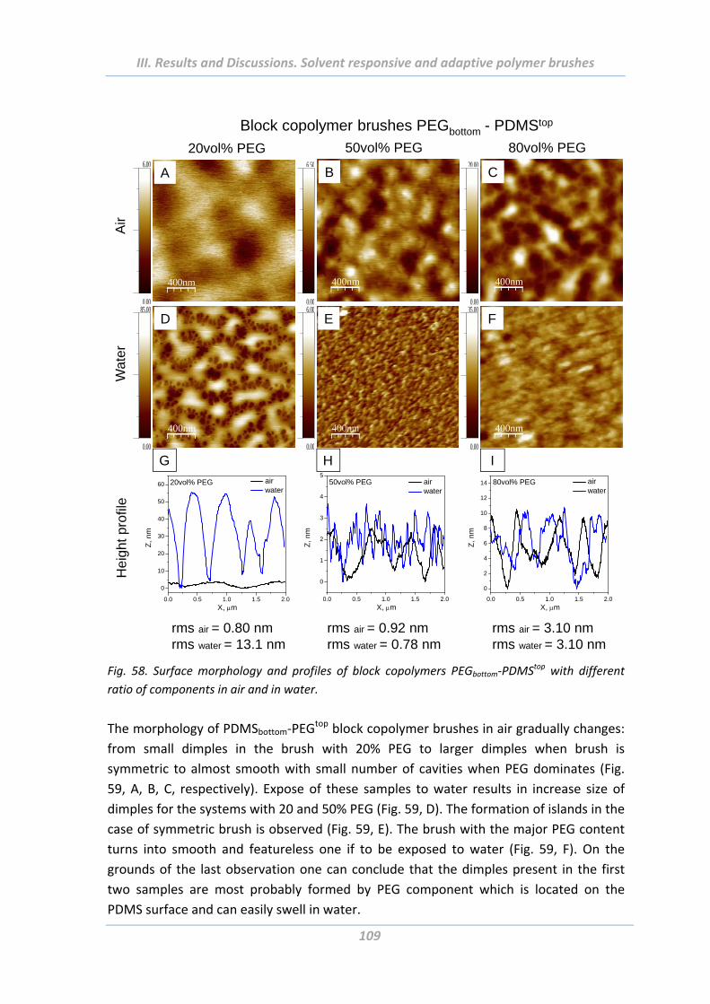
III. Results and Discussions. Solvent responsive and adaptive polymer brushes
109
400nm
50vol% PEG6.50
0.00
400nm
80vol% PEG20.00
0.00
400nm
35.00
0.00
6.00
0.00
400nm
20vol% PEG 6.00
0.00
Air
400nm
85.00
0.00
Wat
erBlock copolymer brushes PEGbottom - PDMStop
A B C
D E F
0.0 0.5 1.0 1.5 2.0
0
10
20
30
40
50
60 air water
20vol% PEG
Z,
nm
X, m0.0 0.5 1.0 1.5 2.0
0
1
2
3
4
5 air water
50vol% PEG
Z,
nm
X, m
rms air = 0.80 nmrms water = 13.1 nm
rms air = 0.92 nmrms water = 0.78 nm
rms air = 3.10 nmrms water = 3.10 nm
0.0 0.5 1.0 1.5 2.0
0
2
4
6
8
10
12
14 air water
80vol% PEG
Z,
nm
X, m
Hei
ght p
rofil
e
G H I
Fig. 58. Surface morphology and profiles of block copolymers PEGbottom‐PDMStop with different
ratio of components in air and in water.
The morphology of PDMSbottom‐PEGtop block copolymer brushes in air gradually changes:
from small dimples in the brush with 20% PEG to larger dimples when brush is
symmetric to almost smooth with small number of cavities when PEG dominates (Fig.
59, A, B, C, respectively). Expose of these samples to water results in increase size of
dimples for the systems with 20 and 50% PEG (Fig. 59, D). The formation of islands in the
case of symmetric brush is observed (Fig. 59, E). The brush with the major PEG content
turns into smooth and featureless one if to be exposed to water (Fig. 59, F). On the
grounds of the last observation one can conclude that the dimples present in the first
two samples are most probably formed by PEG component which is located on the
PDMS surface and can easily swell in water.
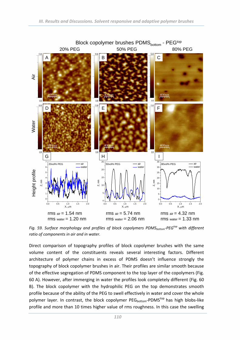
III. Results and Discussions. Solvent responsive and adaptive polymer brushes
110
400nm
13.00
0.00
10.00
0.00
13.00
0.00
20.00
0.00
13.00
0.00
55.00
0.00
20% PEG 50% PEG 80% PEG
Wat
er
Air
Block copolymer brushes PDMSbottom - PEGtop
A B C
D E F
0.0 0.5 1.0 1.5 2.0
0
1
2
3
4
5
6
7 air water
20vol% PEG
Z, n
m
X, m
rms air = 1.54 nmrms water = 1.20 nm
rms air = 5.74 nmrms water = 2.06 nm
rms air = 4.32 nmrms water = 1.33 nm
0.0 0.5 1.0 1.5 2.0
0
5
10
15
20
25 air water
50vol% PEG
Z, n
m
X, m0.0 0.5 1.0 1.5 2.0
0
5
10
15
20
25
30
35 air water
80vol% PEG
Z, n
m
X, m
Hei
ght p
rofil
e
G H I
Fig. 59. Surface morphology and profiles of block copolymers PDMSbottom‐PEG
top with different
ratio of components in air and in water.
Direct comparison of topography profiles of block copolymer brushes with the same
volume content of the constituents reveals several interesting factors. Different
architecture of polymer chains in excess of PDMS doesn’t influence strongly the
topography of block copolymer brushes in air. Their profiles are similar smooth because
of the effective segregation of PDMS component to the top layer of the copolymers (Fig.
60 A). However, after immerging in water the profiles look completely different (Fig. 60
B). The block copolymer with the hydrophilic PEG on the top demonstrates smooth
profile because of the ability of the PEG to swell effectively in water and cover the whole
polymer layer. In contrast, the block copolymer PEGbottom‐PDMStop has high blobs‐like
profile and more than 10 times higher value of rms roughness. In this case the swelling
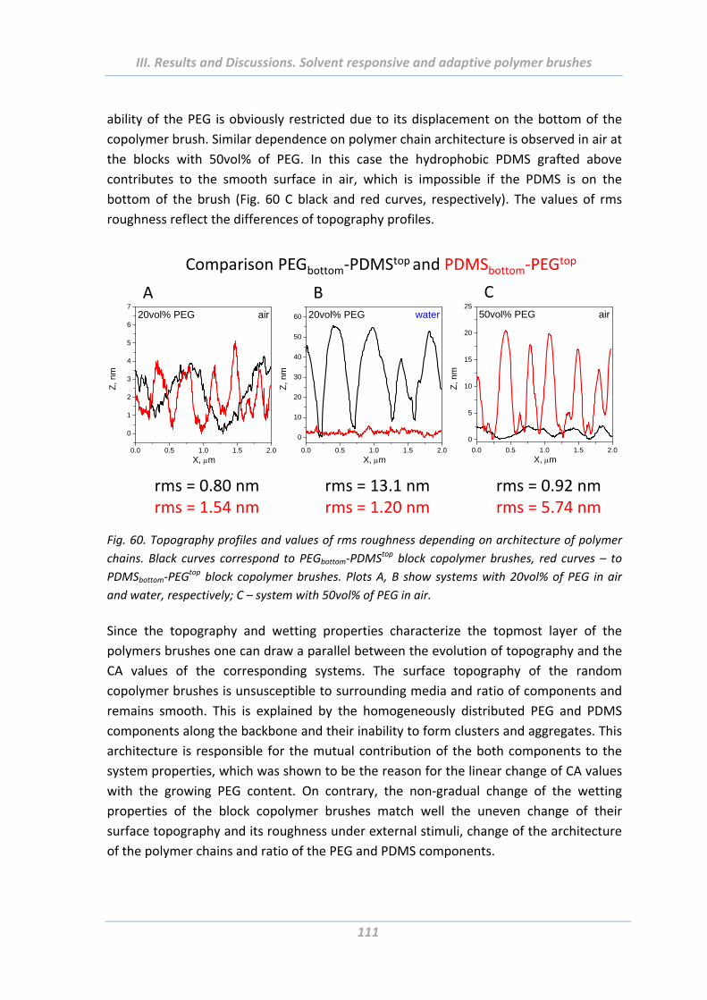
III. Results and Discussions. Solvent responsive and adaptive polymer brushes
111
ability of the PEG is obviously restricted due to its displacement on the bottom of the
copolymer brush. Similar dependence on polymer chain architecture is observed in air at
the blocks with 50vol% of PEG. In this case the hydrophobic PDMS grafted above
contributes to the smooth surface in air, which is impossible if the PDMS is on the
bottom of the brush (Fig. 60 C black and red curves, respectively). The values of rms
roughness reflect the differences of topography profiles.
0.0 0.5 1.0 1.5 2.0
0
10
20
30
40
50
60 water20vol% PEG
Z, n
m
X, m0.0 0.5 1.0 1.5 2.0
0
5
10
15
20
2550vol% PEG
Z, n
mX, m
air
0.0 0.5 1.0 1.5 2.0
0
1
2
3
4
5
6
7air20vol% PEG
Z, n
m
X, m
Comparison PEGbottom‐PDMStop and PDMSbottom‐PEGtop
A B C
rms = 0.80 nmrms = 1.54 nm
rms = 13.1 nmrms = 1.20 nm
rms = 0.92 nmrms = 5.74 nm
Fig. 60. Topography profiles and values of rms roughness depending on architecture of polymer
chains. Black curves correspond to PEGbottom‐PDMStop block copolymer brushes, red curves – to
PDMSbottom‐PEGtop block copolymer brushes. Plots A, B show systems with 20vol% of PEG in air
and water, respectively; C – system with 50vol% of PEG in air.
Since the topography and wetting properties characterize the topmost layer of the
polymers brushes one can draw a parallel between the evolution of topography and the
CA values of the corresponding systems. The surface topography of the random
copolymer brushes is unsusceptible to surrounding media and ratio of components and
remains smooth. This is explained by the homogeneously distributed PEG and PDMS
components along the backbone and their inability to form clusters and aggregates. This
architecture is responsible for the mutual contribution of the both components to the
system properties, which was shown to be the reason for the linear change of CA values
with the growing PEG content. On contrary, the non‐gradual change of the wetting
properties of the block copolymer brushes match well the uneven change of their
surface topography and its roughness under external stimuli, change of the architecture
of the polymer chains and ratio of the PEG and PDMS components.
III. Results and Discussions. Solvent responsive and adaptive polymer brushes
112
2.5 Adhesion properties of solvent responsive and adaptive brushes
Next, adhesion forces of solution‐responsive PEG, PDMS homo‐ and copolymer brushes
with different architectures grafted onto flat and rough substrates were investigated.
The interaction forces were measured on AFM with two types of colloidal probe: with
hydrophilic SiO2 native colloidal probe and with modified colloidal probe with
hydrophobic surface chemistry. Interaction forces were investigated at room
temperature in ambient and aqueous (MilliQ water) media. The colloidal probes were
prepared via gluing of a spherical particle of 4.84 µm mean diameter (Bang Labs, USA)
onto native oxide tipless AFM cantilevers NSC12 of resonant frequency 185‐430kHz
(MikroMasch, Estonia) by a micromanipulator using a two‐component epoxy resin (UHU
plus endfest 300, UHU GmbH, Germany). Spring constant was measured before gluing of
colloidal probe via the method of thermal fluctuation and it was in the order of 7 N/m to
12.5 N/m.
Firstly, several parameters of the AFM force measurements procedure were investigated
to state their influence on adhesion forces and to choose the appropriate values.
2.5.1 Effect of Maximal Load The cantilever with attached colloidal probe approaches and retracts a sample during
the force measurement with the same speed of 300nm/s. When coming into contact
with the surface the colloidal probe executes a certain force on it. The magnitude of this
force, named “Maximal Load” can be adjusted by “Trigger Threshold” parameter in the
AFM software. The load should be strong enough to ensure a good contact with the
surface, but not spoils it. Experiments were done to find out the correlation between
these two parameters and to investigate how they influence the adhesion of a colloidal
probe to the sample surface in air and water. The results obtained on PEG‐PDMSrandom
copolymer brush (with 20vol% PEG content) are presented as an example in Fig. 61. The
dependences are qualitatively relevant for all polymer systems investigated in this
Chapter. The Trigger Threshold was varied between 5 and 45 nm causing a change of the
Maximal Load from 75 to 500nN in air and from 210 to 440nN in water. As expected,
there is a linear dependence between these two parameters in air as well as in water
environment (black curves in Fig. 61, A, B, respectively). As regards the adhesion force in
air, it doesn’t alter significantly upon increasing of Maximal Load (Fig. 61 A, green curve)
–the system is suggests to be in equilibrium [Dre12]. In water, however, the adhesion
force is first constant, then grows quickly till achieves a plateau region that corresponds
to equilibrium state of force measurements (Fig. 61 B, green curve). Though the values
of adhesion forces differ from sample to sample, the values of Maximal Load correspond
to plateau regions are similar independently of the sample. Since the excessive load
could damage scanned surfaces it was decided to perform the AFM force measurements
at 350 nN – the minimum load needed for equilibrium state.
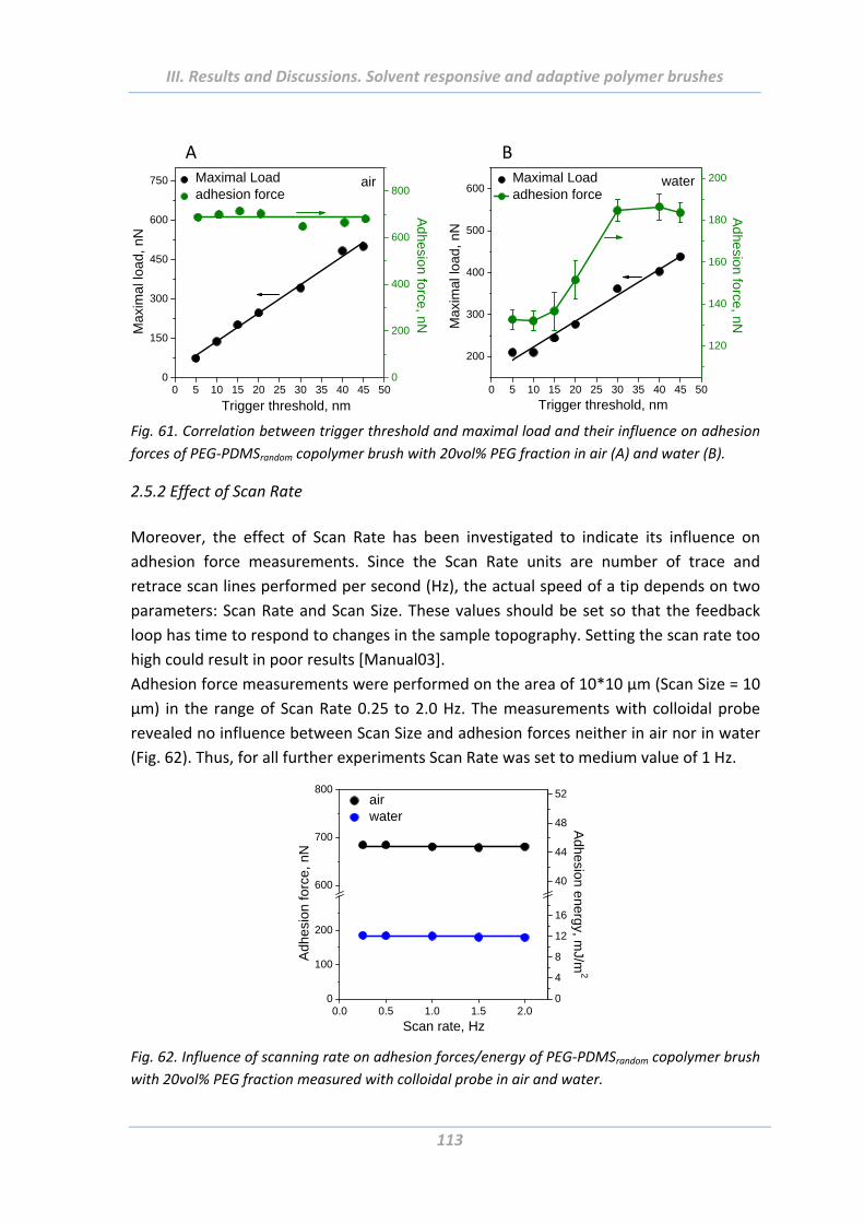
III. Results and Discussions. Solvent responsive and adaptive polymer brushes
113
0 5 10 15 20 25 30 35 40 45 50
200
300
400
500
600 Maximal Load adhesion force
Trigger threshold, nm
Max
imal
load
, nN
120
140
160
180
200water
Adhesion force, nN
0 5 10 15 20 25 30 35 40 45 500
150
300
450
600
750 Maximal Load adhesion force
Trigger threshold, nm
Max
imal
load
, nN
air
0
200
400
600
800
Adhesion force, nN
A B
Fig. 61. Correlation between trigger threshold and maximal load and their influence on adhesion
forces of PEG‐PDMSrandom copolymer brush with 20vol% PEG fraction in air (A) and water (B).
2.5.2 Effect of Scan Rate
Moreover, the effect of Scan Rate has been investigated to indicate its influence on
adhesion force measurements. Since the Scan Rate units are number of trace and
retrace scan lines performed per second (Hz), the actual speed of a tip depends on two
parameters: Scan Rate and Scan Size. These values should be set so that the feedback
loop has time to respond to changes in the sample topography. Setting the scan rate too
high could result in poor results [Manual03].
Adhesion force measurements were performed on the area of 10*10 µm (Scan Size = 10
µm) in the range of Scan Rate 0.25 to 2.0 Hz. The measurements with colloidal probe
revealed no influence between Scan Size and adhesion forces neither in air nor in water
(Fig. 62). Thus, for all further experiments Scan Rate was set to medium value of 1 Hz.
0.0 0.5 1.0 1.5 2.00
100
200
600
700
800 air water
Adh
esio
n fo
rce,
nN
Scan rate, Hz
0
4
8
12
16
40
44
48
52
Adhesion energy, m
J/m2
Fig. 62. Influence of scanning rate on adhesion forces/energy of PEG‐PDMSrandom copolymer brush
with 20vol% PEG fraction measured with colloidal probe in air and water.
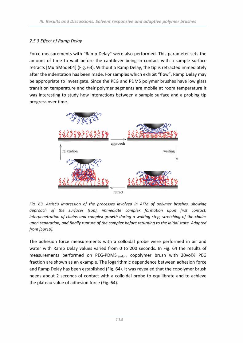
III. Results and Discussions. Solvent responsive and adaptive polymer brushes
114
2.5.3 Effect of Ramp Delay
Force measurements with “Ramp Delay” were also performed. This parameter sets the
amount of time to wait before the cantilever being in contact with a sample surface
retracts [MultiMode04] (Fig. 63). Without a Ramp Delay, the tip is retracted immediately
after the indentation has been made. For samples which exhibit “flow”, Ramp Delay may
be appropriate to investigate. Since the PEG and PDMS polymer brushes have low glass
transition temperature and their polymer segments are mobile at room temperature it
was interesting to study how interactions between a sample surface and a probing tip
progress over time.
Fig. 63. Artist’s impression of the processes involved in AFM of polymer brushes, showing
approach of the surfaces (top), immediate complex formation upon first contact,
interpenetration of chains and complex growth during a waiting step, stretching of the chains
upon separation, and finally rupture of the complex before returning to the initial state. Adapted
from [Spr10].
The adhesion force measurements with a colloidal probe were performed in air and
water with Ramp Delay values varied from 0 to 200 seconds. In Fig. 64 the results of
measurements performed on PEG‐PDMSrandom copolymer brush with 20vol% PEG
fraction are shown as an example. The logarithmic dependence between adhesion force
and Ramp Delay has been established (Fig. 64). It was revealed that the copolymer brush
needs about 2 seconds of contact with a colloidal probe to equilibrate and to achieve
the plateau value of adhesion force (Fig. 64).
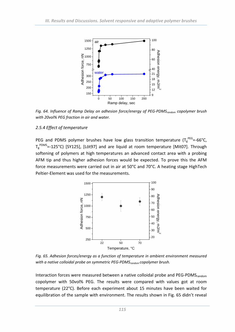
III. Results and Discussions. Solvent responsive and adaptive polymer brushes
115
0 50 100 150 200
150
200
250
300
750
1000
1250
1500
water
Adh
esio
n fo
rce,
nN
Ramp delay, sec
air
9
12
15
18
21
40
60
80
100
Adh
esion en
ergy, m
J/m2
Fig. 64. Influence of Ramp Delay on adhesion force/energy of PEG‐PDMSrandom copolymer brush
with 20vol% PEG fraction in air and water.
2.5.4 Effect of temperature
PEG and PDMS polymer brushes have low glass transition temperature (TgPEG=‐66°C,
TgPDMS=‐125°C) [SY125], [Löt97] and are liquid at room temperature [Mit07]. Through
softening of polymers at high temperatures an advanced contact area with a probing
AFM tip and thus higher adhesion forces would be expected. To prove this the AFM
force measurements were carried out in air at 50°C and 70°C. A heating stage HighTech
Peltier‐Element was used for the measurements.
22 50 70250
500
750
1000
1250
1500
Adh
esio
n fo
rce,
nN
Temperature, °C
20
30
40
50
60
70
80
90
100
Adhesion energy, m
J/m2
Fig. 65. Adhesion forces/energy as a function of temperature in ambient environment measured
with a native colloidal probe on symmetric PEG‐PDMSrandom copolymer brush.
Interaction forces were measured between a native colloidal probe and PEG‐PDMSrandom
copolymer with 50vol% PEG. The results were compared with values got at room
temperature (22°C). Before each experiment about 15 minutes have been waited for
equilibration of the sample with environment. The results shown in Fig. 65 didn’t reveal
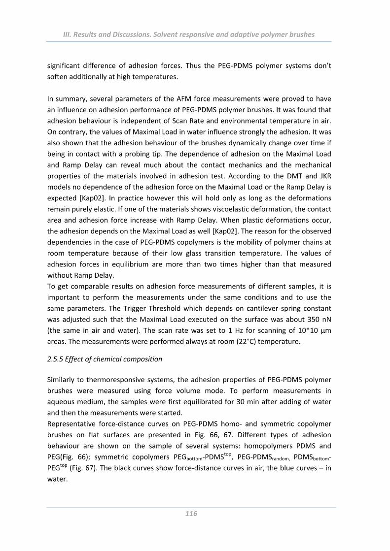
III. Results and Discussions. Solvent responsive and adaptive polymer brushes
116
significant difference of adhesion forces. Thus the PEG‐PDMS polymer systems don’t
soften additionally at high temperatures.
In summary, several parameters of the AFM force measurements were proved to have
an influence on adhesion performance of PEG‐PDMS polymer brushes. It was found that
adhesion behaviour is independent of Scan Rate and environmental temperature in air.
On contrary, the values of Maximal Load in water influence strongly the adhesion. It was
also shown that the adhesion behaviour of the brushes dynamically change over time if
being in contact with a probing tip. The dependence of adhesion on the Maximal Load
and Ramp Delay can reveal much about the contact mechanics and the mechanical
properties of the materials involved in adhesion test. According to the DMT and JKR
models no dependence of the adhesion force on the Maximal Load or the Ramp Delay is
expected [Kap02]. In practice however this will hold only as long as the deformations
remain purely elastic. If one of the materials shows viscoelastic deformation, the contact
area and adhesion force increase with Ramp Delay. When plastic deformations occur,
the adhesion depends on the Maximal Load as well [Kap02]. The reason for the observed
dependencies in the case of PEG‐PDMS copolymers is the mobility of polymer chains at
room temperature because of their low glass transition temperature. The values of
adhesion forces in equilibrium are more than two times higher than that measured
without Ramp Delay.
To get comparable results on adhesion force measurements of different samples, it is
important to perform the measurements under the same conditions and to use the
same parameters. The Trigger Threshold which depends on cantilever spring constant
was adjusted such that the Maximal Load executed on the surface was about 350 nN
(the same in air and water). The scan rate was set to 1 Hz for scanning of 10*10 µm
areas. The measurements were performed always at room (22°C) temperature.
2.5.5 Effect of chemical composition
Similarly to thermoresponsive systems, the adhesion properties of PEG‐PDMS polymer
brushes were measured using force volume mode. To perform measurements in
aqueous medium, the samples were first equilibrated for 30 min after adding of water
and then the measurements were started.
Representative force‐distance curves on PEG‐PDMS homo‐ and symmetric copolymer
brushes on flat surfaces are presented in Fig. 66, 67. Different types of adhesion
behaviour are shown on the sample of several systems: homopolymers PDMS and
PEG(Fig. 66); symmetric copolymers PEGbottom‐PDMStop, PEG‐PDMSrandom, PDMSbottom‐
PEGtop (Fig. 67). The black curves show force‐distance curves in air, the blue curves – in
water.
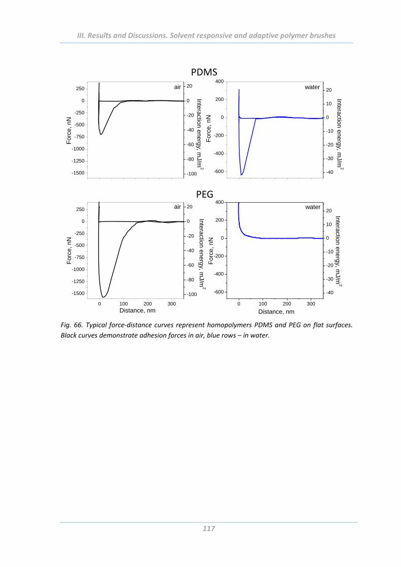
III. Results and Discussions. Solvent responsive and adaptive polymer brushes
117
-1500
-1250
-1000
-750
-500
-250
0
250 air
-100
-80
-60
-40
-20
0
20
For
ce,
nN
Interaction energy, m
J/m2
-600
-400
-200
0
200
400water
-40
-30
-20
-10
0
10
20
For
ce,
nN
Interaction energy, m
J/m2
0 100 200 300
-600
-400
-200
0
200
400
Distance, nm
For
ce,
nN
-40
-30
-20
-10
0
10
20
Intera
ction e
ne
rgy, mJ/m
2
water
0 100 200 300
-1500
-1250
-1000
-750
-500
-250
0
250
For
ce, n
N
Intera
ction e
ne
rgy, m
J/m2
Distance, nm
-100
-80
-60
-40
-20
0
20air
PDMS
PEG
Fig. 66. Typical force‐distance curves represent homopolymers PDMS and PEG on flat surfaces.
Black curves demonstrate adhesion forces in air, blue rows – in water.
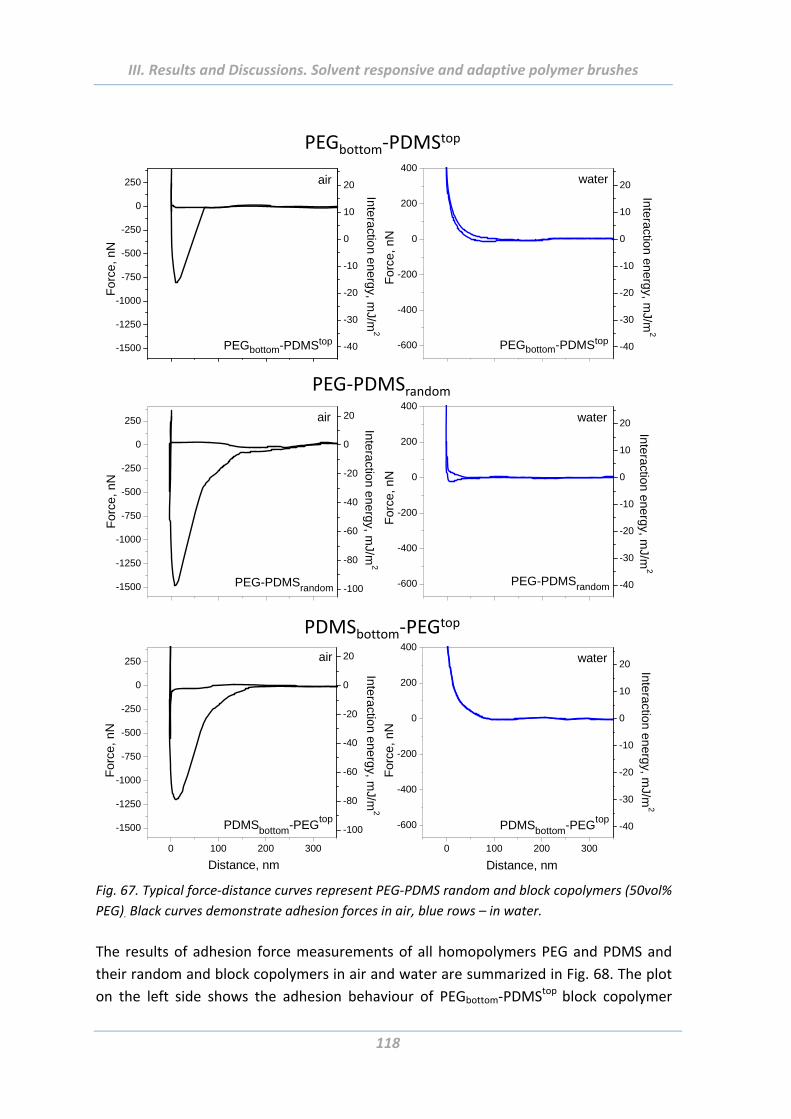
III. Results and Discussions. Solvent responsive and adaptive polymer brushes
118
-600
-400
-200
0
200
400
PEG-PDMSrandom
For
ce, n
N
water
-40
-30
-20
-10
0
10
20
Interaction energy, mJ/m
2
-1500
-1250
-1000
-750
-500
-250
0
250 air
PEG-PDMSrandom -100
-80
-60
-40
-20
0
20
For
ce,
nN
Interaction energy, mJ/m
2
-1500
-1250
-1000
-750
-500
-250
0
250
Fo
rce,
nN
PEGbottom-PDMStop -40
-30
-20
-10
0
10
20
Inte
ractio
n en
erg
y, mJ/m
2
air
-600
-400
-200
0
200
400
Fo
rce,
nN
-40
-30
-20
-10
0
10
20
PEGbottom-PDMStop
Inte
raction
ene
rgy, m
J/m2
water
0 100 200 300
-600
-400
-200
0
200
400
Distance, nm
water
For
ce, n
N
-40
-30
-20
-10
0
10
20
PDMSbottom-PEGtop
Interaction energy, m
J/m2
0 100 200 300
-1500
-1250
-1000
-750
-500
-250
0
250
Distance, nm
air
PDMSbottom-PEGtop
For
ce, n
N
-100
-80
-60
-40
-20
0
20
Interaction energy, m
J/m2
PEGbottom‐PDMStop
PDMSbottom‐PEGtop
PEG‐PDMSrandom
Fig. 67. Typical force‐distance curves represent PEG‐PDMS random and block copolymers (50vol%
PEG). Black curves demonstrate adhesion forces in air, blue rows – in water.
The results of adhesion force measurements of all homopolymers PEG and PDMS and
their random and block copolymers in air and water are summarized in Fig. 68. The plot
on the left side shows the adhesion behaviour of PEGbottom‐PDMStop block copolymer

III. Results and Discussions. Solvent responsive and adaptive polymer brushes
119
brushes; the plot in the middle corresponds to PEG‐PDMSrandom copolymer brushes; the
plot on the right side represents block copolymers PDMSbottom‐PEGtop. There is an
increase of PEG volume content from left to right on each plot. The “PDMS” and “PEG”
on the X axis correspond to PDMS and PEG homopolymer brushes.
The homopolymer brushes PEG and PDMS are both adhesive to colloidal probe in the
dry state. However, their behaviour changes completely in water. While the PDMS is still
tacky in water because of hydrophobic interactions (Fig. 68 A – in air, D – in water), the
PEG becomes completely non‐adhesive due to strong hydration of polymer chains.
In the case of block and random copolymers, exposure of the brushes to water results in
changing of their adhesive interactions with the colloidal probe. Initially strongly
adhesive to colloidal probe in air, the brushes become low‐ or even non‐adhesive in
water. Notably, with growing PEG volume content the adhesion forces increase in air
and decrease in water. This behaviour is relevant for all systems independently of
architecture of polymer chains (Fig. 68). The block copolymer polymer brushes with
more than 50vol% PEG content are completely non‐adhesive in water (Fig. 68, blue
columns).
PDMS 20% 50% 80% PEG0
200
400
600
800
1000
1200
1400
1600
Adh
esio
n fo
rce,
nN
PEG volume content
air water
block PEGbottom
-PDMStop
PDMS 20% 50% 80% PEG
PEG volume content
air water
PEG-PDMSrandom
PDMS 20% 50% 80% PEG
PEG volume content
air water
block PDMSbottom
-PEGtop
0
15
30
45
60
75
90
105
Adhesion energy, m
J/m2
Fig. 68. Results of adhesion force measurements on homopolymer brushes PEG and PDMS and
their random and block copolymers versus PEG volume content in air (transparent columns) and
water (blue columns).
2.5.6 Effect of length of polymer chain
The effect of the polymer layer thickness on adhesion forces was investigated via AFM
force measurements with a native colloidal probe in air and in water. “Thin” polymer
brushes were about 15 nm, whereas the “thick” polymer chains had about 40 nm.
Interestingly, the chain length of PEG‐PDMS copolymer brushes influences their
adhesion behaviour strongly. Note, the 40 nm thick brushes are more adhesive than 15
nm ones (Fig. 69, thick brushes are shown with filled columns, thin brushes – with empty
columns). Homopolymer brushes demonstrated similar tendencies. The difference
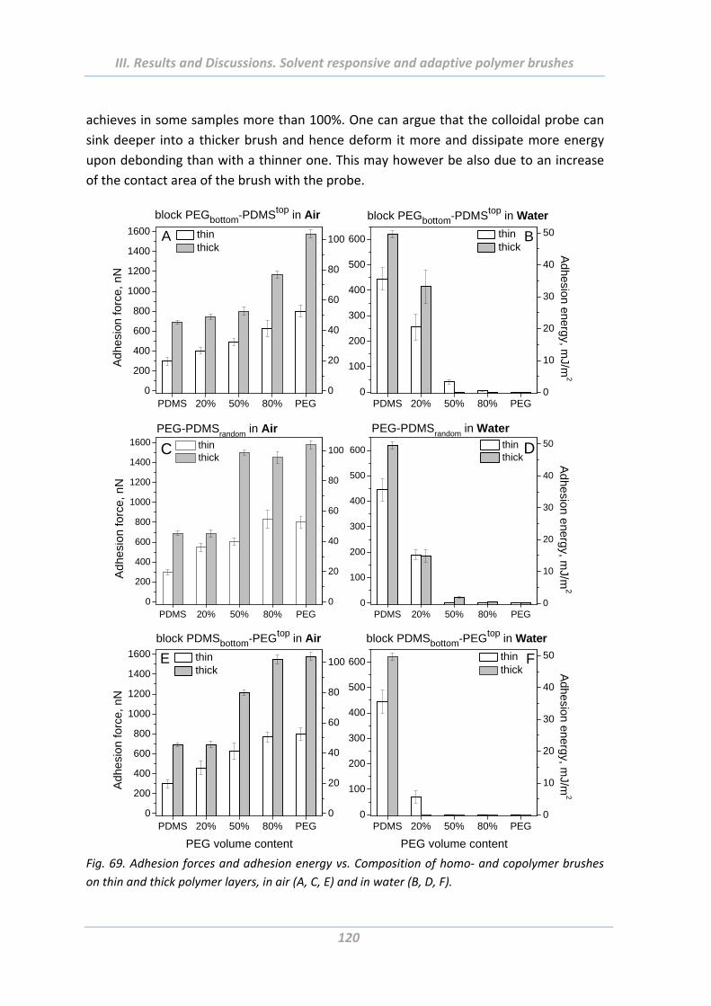
III. Results and Discussions. Solvent responsive and adaptive polymer brushes
120
achieves in some samples more than 100%. One can argue that the colloidal probe can
sink deeper into a thicker brush and hence deform it more and dissipate more energy
upon debonding than with a thinner one. This may however be also due to an increase
of the contact area of the brush with the probe.
PDMS 20% 50% 80% PEG0
200
400
600
800
1000
1200
1400
1600
block PEGbottom-PDMStop in Air
Adh
esio
n fo
rce,
nN
thin thick
A
0
20
40
60
80
100
PDMS 20% 50% 80% PEG0
100
200
300
400
500
600
block PEGbottom-PDMStop in Water
thin thick
B
0
10
20
30
40
50
Adhesion energy, m
J/m2
PDMS 20% 50% 80% PEG0
200
400
600
800
1000
1200
1400
1600
Adh
esio
n fo
rce,
nN
thin thick
PEG-PDMSrandom in Air
C
0
20
40
60
80
100
PDMS 20% 50% 80% PEG0
200
400
600
800
1000
1200
1400
1600
block PDMSbottom-PEGtop in Air
Adh
esio
n fo
rce,
nN
PEG volume content
thin thick
E
0
20
40
60
80
100
PDMS 20% 50% 80% PEG0
100
200
300
400
500
600
block PDMSbottom-PEGtop in Water
PEG volume content
thin thick
F
0
10
20
30
40
50
Adhesion energy, m
J/m2
PDMS 20% 50% 80% PEG0
100
200
300
400
500
600
PEG-PDMSrandom in Water thin thick
D
0
10
20
30
40
50
Ad
hesion energ
y, mJ/m
2
Fig. 69. Adhesion forces and adhesion energy vs. Composition of homo‐ and copolymer brushes
on thin and thick polymer layers, in air (A, C, E) and in water (B, D, F).
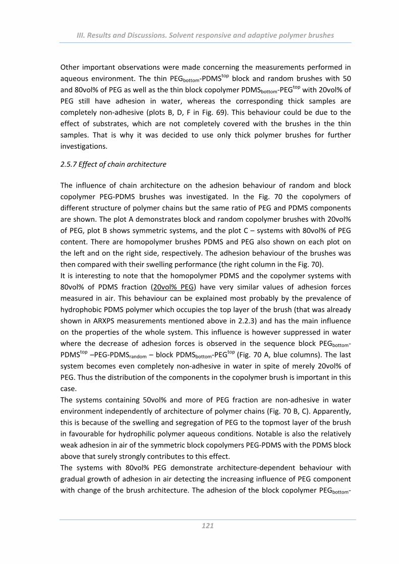
III. Results and Discussions. Solvent responsive and adaptive polymer brushes
121
Other important observations were made concerning the measurements performed in
aqueous environment. The thin PEGbottom‐PDMStop block and random brushes with 50
and 80vol% of PEG as well as the thin block copolymer PDMSbottom‐PEGtop with 20vol% of
PEG still have adhesion in water, whereas the corresponding thick samples are
completely non‐adhesive (plots B, D, F in Fig. 69). This behaviour could be due to the
effect of substrates, which are not completely covered with the brushes in the thin
samples. That is why it was decided to use only thick polymer brushes for further
investigations.
2.5.7 Effect of chain architecture
The influence of chain architecture on the adhesion behaviour of random and block
copolymer PEG‐PDMS brushes was investigated. In the Fig. 70 the copolymers of
different structure of polymer chains but the same ratio of PEG and PDMS components
are shown. The plot A demonstrates block and random copolymer brushes with 20vol%
of PEG, plot B shows symmetric systems, and the plot C – systems with 80vol% of PEG
content. There are homopolymer brushes PDMS and PEG also shown on each plot on
the left and on the right side, respectively. The adhesion behaviour of the brushes was
then compared with their swelling performance (the right column in the Fig. 70).
It is interesting to note that the homopolymer PDMS and the copolymer systems with
80vol% of PDMS fraction (20vol% PEG) have very similar values of adhesion forces
measured in air. This behaviour can be explained most probably by the prevalence of
hydrophobic PDMS polymer which occupies the top layer of the brush (that was already
shown in ARXPS measurements mentioned above in 2.2.3) and has the main influence
on the properties of the whole system. This influence is however suppressed in water
where the decrease of adhesion forces is observed in the sequence block PEGbottom‐
PDMStop –PEG‐PDMSrandom – block PDMSbottom‐PEGtop (Fig. 70 A, blue columns). The last
system becomes even completely non‐adhesive in water in spite of merely 20vol% of
PEG. Thus the distribution of the components in the copolymer brush is important in this
case.
The systems containing 50vol% and more of PEG fraction are non‐adhesive in water
environment independently of architecture of polymer chains (Fig. 70 B, C). Apparently,
this is because of the swelling and segregation of PEG to the topmost layer of the brush
in favourable for hydrophilic polymer aqueous conditions. Notable is also the relatively
weak adhesion in air of the symmetric block copolymers PEG‐PDMS with the PDMS block
above that surely strongly contributes to this effect.
The systems with 80vol% PEG demonstrate architecture‐dependent behaviour with
gradual growth of adhesion in air detecting the increasing influence of PEG component
with change of the brush architecture. The adhesion of the block copolymer PEGbottom‐
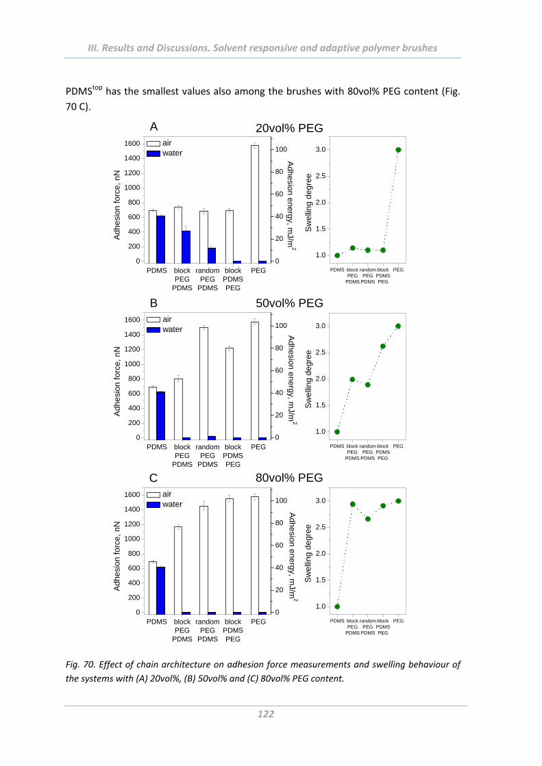
III. Results and Discussions. Solvent responsive and adaptive polymer brushes
122
PDMStop has the smallest values also among the brushes with 80vol% PEG content (Fig.
70 C).
PDMS blockPEG
PDMS
randomPEG
PDMS
blockPDMSPEG
PEG0
200
400
600
800
1000
1200
1400
1600 air water
Ad
he
sio
n f
orc
e,
nN
PDMS blockPEG
PDMS
randomPEG
PDMS
blockPDMSPEG
PEG
1.0
1.5
2.0
2.5
3.0
Sw
elli
ng
de
gre
e
0
20
40
60
80
100
Ad
he
sion
en
erg
y, mJ/m
2
PDMS blockPEG
PDMS
randomPEG
PDMS
blockPDMSPEG
PEG0
200
400
600
800
1000
1200
1400
1600 air water
Ad
he
sio
n f
orc
e,
nN
PDMS blockPEG
PDMS
randomPEG
PDMS
blockPDMSPEG
PEG
1.0
1.5
2.0
2.5
3.0
Sw
elli
ng
de
gre
e
0
20
40
60
80
100
Adh
esion
en
erg
y, mJ/m
2
PDMS blockPEG
PDMS
randomPEG
PDMS
blockPDMSPEG
PEG0
200
400
600
800
1000
1200
1400
1600 air water
Adh
esio
n fo
rce,
nN
PDMS blockPEG
PDMS
randomPEG
PDMS
blockPDMSPEG
PEG
1.0
1.5
2.0
2.5
3.0
Adhesion energy, m
J/m2
Sw
ellin
g de
gree
0
20
40
60
80
100
20vol% PEG
50vol% PEG
80vol% PEG
A
B
C
Fig. 70. Effect of chain architecture on adhesion force measurements and swelling behaviour of
the systems with (A) 20vol%, (B) 50vol% and (C) 80vol% PEG content.
III. Results and Discussions. Solvent responsive and adaptive polymer brushes
123
Next, the adhesion properties of brushes were compared with their swelling behaviour
in water environment. Since the PDMS is hydrophobic and doesn’t swell in water, the
swelling ability of the copolymer brushes corresponds to the hydrophilic PEG
component. Therefore, the swelling degree of the copolymers with 80vol% PDMS is
close to that measured on homopolymer PDMS. The influence of chains’ architecture
was not registered, neither on swelling behaviour of the brushes, nor on their adhesion
force values (Fig. 70 A). The similar, nearly constant behaviour is observed on the brush
with 80vol% PEG. The plateau character is related to both parameters, degree of
swelling and adhesion performance in water (Fig. 70 C). The symmetric brushes
demonstrate growth of adhesion forces and swelling degrees in the sequence PEGbottom‐
PDMStop – PEG‐PDMSrandom– block PDMSbottom‐PEGtop (Fig. 70 B).
In general, the systems that contain at least 50vol% PEG and that have swelling degree
≥2, are non‐adhesive in water independently on polymer chains architecture. The reason
for this should be the overwhelming influence of the PEG major component that swells
very well in water and makes the whole system non‐adhesive. The disposition of PEG is
thus of minor importance. The only non‐adhesive system in water environment with low
swelling degree is the block copolymer brush PDMSbottom‐PEGtop with 20vol% PEG
content. In this case the determinant factor – is the top layer position of PEG that even
at low content can influence significantly the adhesion performance of the brush making
it completely non‐adhesive in water.
All mentioned observations confirm the ideas already expressed while speaking about
the wetting and swelling properties of the copolymer brushes. In some cases there is a
clear influence of the chain architecture on the adhesion behaviour of copolymers. For
the most part this can be explained by different extent of spatial hindrance in the
brushes having different distribution of side chains. This influences the ability of the
brushes to rearrange their chains upon changing environmental conditions. The
component placed on the top of block copolymer brush contributes stronger to the
surface properties, in particular their adhesion behaviour on the whole system, as that
placed on the bottom. For a component beneath, there is a spatial hindrance to
segregate on the top of the polymeric layer and to contribute to the properties of the
system in whole. For example, even upon conditions favourable for hydrophilic PEG the
block copolymer brush PEGbottom‐PDMStop and the random brush of the same
composition (20vol% of PEG) have relatively strong adhesion in water, whereas the
block with the PEG on the top is non‐adhesive. The random brushes have mostly
intermediate values of adhesion between the both block copolymers. In general, a clear
correlation between the adhesion properties of the PEG‐PDMS copolymer brushes and
their swelling behaviour was shown.
III. Results and Discussions. Solvent responsive and adaptive polymer brushes
124
2.5.8 Effect of surface roughness
To study the effect of surface roughness on adhesion behaviour of PEG‐PDMS homo‐
and copolymer brushes, the samples grown from rough substrates made of 1µm large
spherical particles were investigated via colloidal probe technique on AFM. The
measurements were performed in ambient and aqueous conditions at room
temperature. In Fig. 71 the results are summarized: the plots in the left column show the
values of adhesion forces and adhesion energy of each type of PEG‐PDMS copolymer
brushes measured in air dependently on the PEG volume fraction, whereas the plots on
the right side represent the analogous measurements in water. The empty columns
reflect the adhesion values of the flat surfaces, the filled columns – the rough ones.
The adhesion forces measured on rough surfaces in air show a sharp decrease
comparatively to the flat ones. This behaviour is typical for all the PEG‐PDMS homo‐ and
copolymer brushes (Fig. 71 A, C, E). Similarly to the measurements on the
thermoresponsive polymer brushes, the decrease of adhesion on rough surfaces is
attributed to the reduction of contact area between the rough surface and a colloidal
probe while scanning [Tor05], [Sku00]. On the other hand, the measurements in water
have often an opposite character (Fig. 71 B, D, F). The values of adhesion forces are
quite large on rough surfaces whereas the corresponding flat samples are completely
non‐adhesive. This could be explained by the effect of substrate that is possibly not
completely screened by polymer layers. However, the tendency of the increasing
adhesion forces in air and decreasing in water with growing PEG content is similar on flat
and on rough substrates.
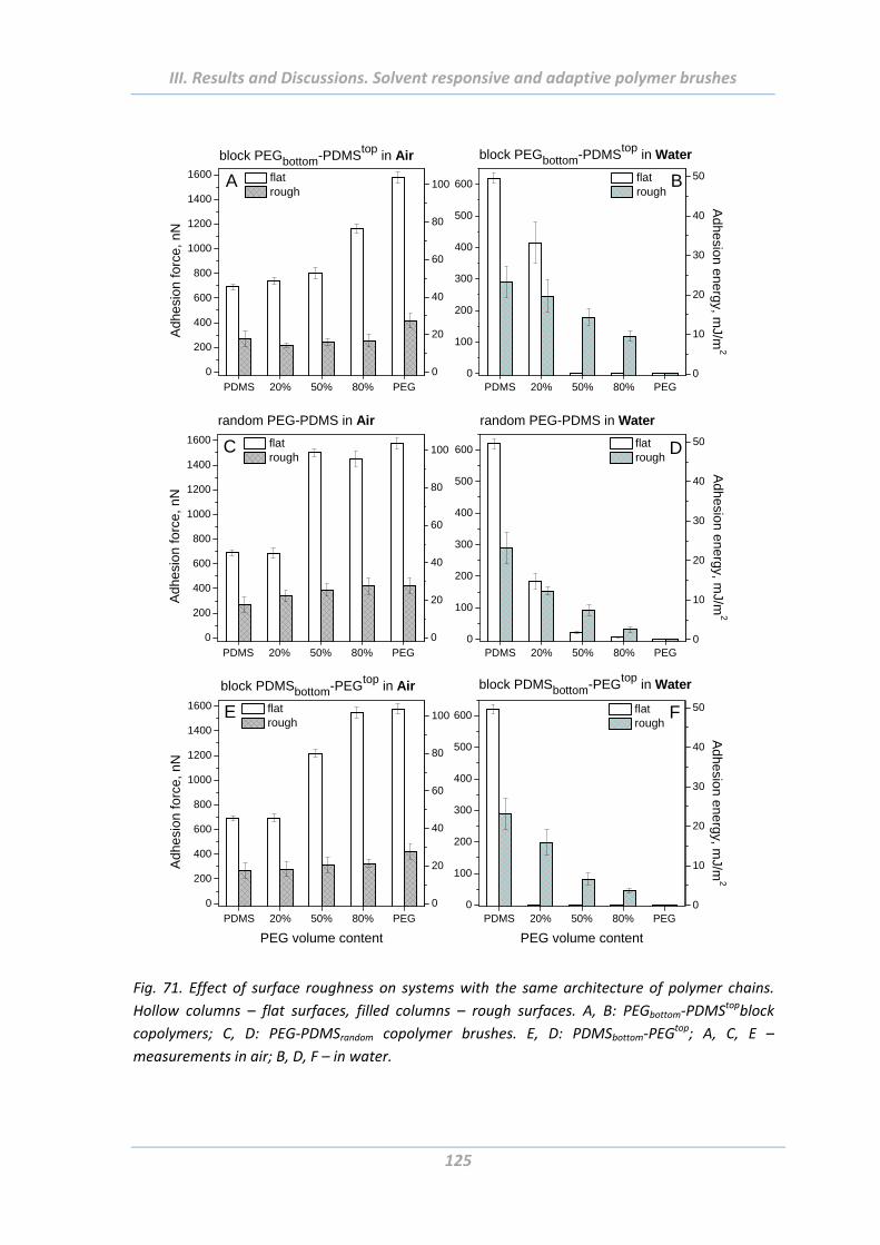
III. Results and Discussions. Solvent responsive and adaptive polymer brushes
125
PDMS 20% 50% 80% PEG
0
200
400
600
800
1000
1200
1400
1600
block PEGbottom-PDMStop in Air
Adh
esio
n fo
rce,
nN
flat rough
A
0
20
40
60
80
100
PDMS 20% 50% 80% PEG0
100
200
300
400
500
600
block PEGbottom-PDMStop in Water
flat rough
B
0
10
20
30
40
50A
dhesion energy, mJ/m
2
PDMS 20% 50% 80% PEG0
100
200
300
400
500
600 flat rough
random PEG-PDMS in Water
D
0
10
20
30
40
50
Adhesio
n energy, mJ/m
2
PDMS 20% 50% 80% PEG
0
200
400
600
800
1000
1200
1400
1600
Adh
esio
n fo
rce,
nN
flat rough
random PEG-PDMS in Air
C
0
20
40
60
80
100
PDMS 20% 50% 80% PEG
0
200
400
600
800
1000
1200
1400
1600
block PDMSbottom-PEGtop in Air
Adh
esio
n fo
rce,
nN
PEG volume content
flat rough
E
0
20
40
60
80
100
PDMS 20% 50% 80% PEG0
100
200
300
400
500
600
block PDMSbottom-PEGtop in Water
PEG volume content
flat rough
F
0
10
20
30
40
50
Adhesio
n energy, mJ/m
2
Fig. 71. Effect of surface roughness on systems with the same architecture of polymer chains.
Hollow columns – flat surfaces, filled columns – rough surfaces. A, B: PEGbottom‐PDMStopblock
copolymers; C, D: PEG‐PDMSrandom copolymer brushes. E, D: PDMSbottom‐PEGtop; A, C, E –
measurements in air; B, D, F – in water.
III. Results and Discussions. Solvent responsive and adaptive polymer brushes
126
2.5.9 Effect of surface functionality of colloidal probe
Until now all shown results on adhesion force measurements were about interactions
between a sample surface and a hydrophilic colloidal probe (native silica particle). To
study the effect of colloidal probe with another surface functionality on adhesion
behaviour of PEG‐PDMS homo‐ and copolymer brushes, the experiments with
hydrophobic colloidal probe have been performed. To provide a colloidal probe with
such functionality the tipless cantilevers (NSC12 MikroMasch, resonant frequency 185‐
430 kHz, spring constant 7‐12.5 N/m) with previously attached native silica colloidal
particles of 4.84 µm in diameter were placed for 4 hours in exsiccator with a
1H,1H,2H,2H‐Perfluorodecyltrichlorosilane (PFDTS). PFDTS is often used to control the
surface chemistry and to achieve ultrahydrophobic and super‐repellent surfaces [Raz10].
The common adhesion force measurements were carried out afterwards. In the Fig. 72
the results of the measurements are summarized: the left column represents the
adhesion force/energy of the samples in air (empty columns) and water (filled columns)
with hydrophilic colloidal probe, the right column – with hydrophobic one. The
investigations were performed on flat samples modified with homo‐, random and block
copolymer brushes.
First of all, the homopolymers PEG and PDMS demonstrate dissimilar adhesion
behaviour if probed with the hydrophobic CP. Though the PDMS is similar adhesive in
both media, the values are about 4 times higher than that measured with a native CP.
The PEG is turned out to be less adhesive than the PDMS, but the value is similar to that
measured with the native CP. The PEG is non‐adhesive in water independently of the
surface chemistry of the probing tip.
The overall tendencies of adhesion forces/energy on the random and block copolymer
brushes have a clear difference. The copolymer brushes measured with hydrophobic CP
become less adhesive with growing PEG content whereas the results achieved with the
native CP have just an opposite trend: their adhesion increases. Moreover, the block
copolymers PEGbottom‐PDMStop have in general significantly stronger adhesion in air when
measured with the hydrophobic CP (Fig. 72 A, B). The random systems with 50 and
80vol% of PEG are about 3 times less adhesive in air, but similar to native CP almost non‐
adhesive in water (Fig. 72 C, D). The block copolymer brushes PDMSbottom‐PEGtop are non‐
adhesive in water (Fig. 72 E, F).
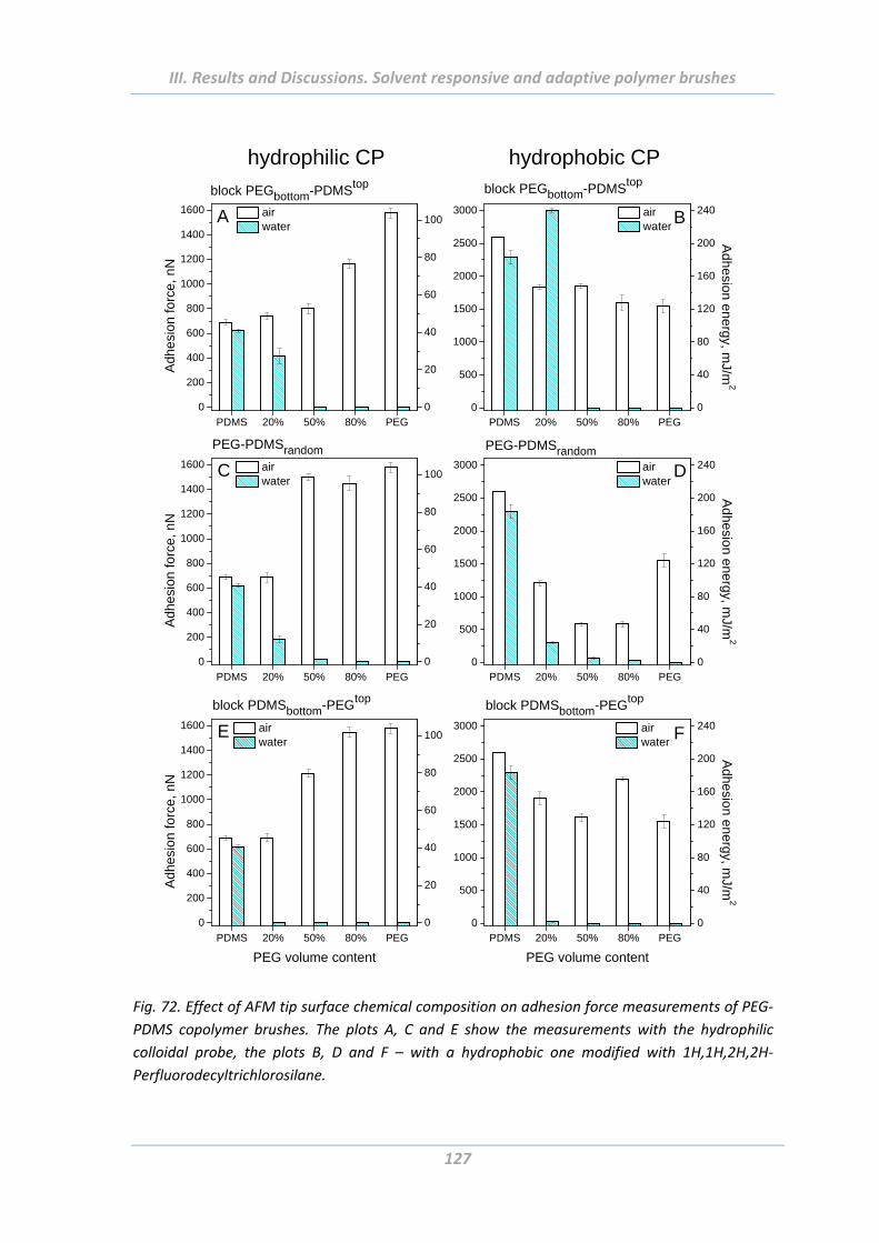
III. Results and Discussions. Solvent responsive and adaptive polymer brushes
127
PDMS 20% 50% 80% PEG
0
200
400
600
800
1000
1200
1400
1600
block PEGbottom-PDMStopA
dhes
ion
forc
e, n
N
air water
A
0
20
40
60
80
100
PDMS 20% 50% 80% PEG0
500
1000
1500
2000
2500
3000
block PEGbottom-PDMStop
air water
B
0
40
80
120
160
200
240
Adhesion energy, m
J/m2
PDMS 20% 50% 80% PEG
0
200
400
600
800
1000
1200
1400
1600
PEG-PDMSrandom
Adh
esio
n fo
rce,
nN
air water
C
0
20
40
60
80
100
PDMS 20% 50% 80% PEG0
500
1000
1500
2000
2500
3000
PEG-PDMSrandom air water
D
0
40
80
120
160
200
240
Adhesio
n energy, mJ/m
2
PDMS 20% 50% 80% PEG
0
200
400
600
800
1000
1200
1400
1600
block PDMSbottom-PEGtop
Adh
esio
n fo
rce,
nN
PEG volume content
air water
E
0
20
40
60
80
100
PDMS 20% 50% 80% PEG0
500
1000
1500
2000
2500
3000
block PDMSbottom-PEGtop
PEG volume content
air water
F
0
40
80
120
160
200
240
Adhesio
n energy, mJ/m
2
hydrophilic CP hydrophobic CP
Fig. 72. Effect of AFM tip surface chemical composition on adhesion force measurements of PEG‐
PDMS copolymer brushes. The plots A, C and E show the measurements with the hydrophilic
colloidal probe, the plots B, D and F – with a hydrophobic one modified with 1H,1H,2H,2H‐
Perfluorodecyltrichlorosilane.
III. Results and Discussions. Solvent responsive and adaptive polymer brushes
128
The described observations can be explained by preferential adhesion of hydrophilic
colloidal probe to hydrophilic PEG and hydrophobic colloidal probe to hydrophobic
PDMS. In water however the adhesion decreases with increase of PEG fraction
independently of surface chemistry of colloidal probe.
2.6 Summary
Solvent responsive polymer brushes based on hydrophilic PEG and hydrophobic PDMS
polymers were synthesised using AGET ATRP. Depending on distribution of PEG and
PDMS side chains along the methacrylate backbone three types of architecture were
possible: random copolymer brushes with homogeneously distributed PEG and PDMS
components; block copolymer brushes ones where the PDMS is on the top and PEG on
the bottom of the backbone, and block copolymer brushes with inverse sequence: PEG –
on the top and PDMS – on the bottom. Moreover, the ratio of components has been
varied: 20vol% PEG and 80vol% PDMS, 80vol% PEG and 20vol% PDMS, and symmetric
50vol% PEG and 50vol% PDMS brushes. Homopolymers PEG and PDMS have been also
prepared and used for comparison with the copolymer systems. All polymer brushes
were synthesised on flat surfaces and on rough ones made of 1 µm large spherical
particles.
The resulted composition of the synthesised block and random copolymer brushes was
examined by means of ellipsometric and XPS measurements, respectively, and was
shown to correspond to the desired ratios.
The surface charges and morphology, wetting and swelling properties were
systematically studied and discussed. Surface topography of the PEG‐PDMSrandom
copolymer brushes were shown to be smooth and featureless in both media that
correlates well with their gradually changing swelling and wetting properties with
growing PEG content. This is explained by the homogeneously distributed PEG and
PDMS side chains along the backbone and their mutual contribution to the properties of
the copolymer brush in whole. On the other hand, the block copolymer brushes have
various and often rough topography depending on architecture of polymer chains and
surrounding media. The non‐linear evolution of the surface properties, swelling and
wetting, of the block copolymers matches well their topography.
Using the colloidal probe technique for the AFM force measurements the adhesion
properties of the homo‐ and copolymer brushes were thoroughly investigated. Influence
of several parameters of scanning procedure was first studied in details. The force
executed by a tip on the sample surface (Maximal Load) has often contradictory
influence of adhesion performance of investigated surfaces depending on surface
properties and geometry of probing tip [Cro05], [Gre07], [Kim06]. In the present work
the preload was found to influence significantly the adhesion forces measured in water.
III. Results and Discussions. Solvent responsive and adaptive polymer brushes
129
This was attributed to the non‐equilibrium state and most probably viscoelastic
deformation of the systems under probing with an AFM tip until a certain pressure is
employed. In air however such influence of Maximal Load wasn’t observed.
The adhesion force measurements with different scan rates and at elevated
temperatures didn’t reveal any influences on adhesion values. Experiments with
different Ramp Delay that expresses the contact time between a tip and a sample
surface during the adhesion force measurements were also performed. It was shown
that the PEG‐PDMS homo‐ and copolymer brushes become more adhesive with
increasing time of contact with a CP and a certain time is needed to achieve equilibrium.
Since the polymers have low glass transition temperature their chains are mobile at
room temperature and are able to rearrange their structure in order to achieve the
energy favourable state. For all further experiments identical parameters of scanning
were used.
Next, the influence of several factors on adhesion behaviour of the brushes in changing
environmental conditions (air and water) has been investigated in details: the effect of
chemical composition of the polymer chains, the length of the polymer chains, chain
architecture, surface roughness of substrates where the brushes are grafted and surface
functionality of colloidal probes.
The general tendency found for the interaction forces between the PEG‐PDMS
copolymer brushes and hydrophilic CP is the increase of adhesion forces in air and
decrease in water with growing PEG content. As it was shown by the ARXPS, the
hydrophobic PDMS predominantly occupy the topmost layer of the random copolymer
brushes in air but the fraction is decreasing with growing PEG volume fraction. The
investigations of the wetting properties showed reduce of the CA values in water with
growing PEG content. Obviously, the rearrangement of the brush structure takes place
with the change of solvent. The reason for this behaviour (already observed by the
group of Minko [Mot07], [She08]) is the ability of the PEG and PDMS polymer chains to
move in response to the external stimuli. They are flexible at room temperature due to
their low Tg. The component that occupies the top layer contributes stronger to the
surface properties of the whole copolymer brush. Thus, the surface properties of the
PEG‐PDMS copolymer brushes are determined by the hydrophobic PDMS in air and
hydrophilic PEG in water.
The same trends were revealed on thin (15 nm) as well as on thick (40 nm) polymer
layers. The values of adhesion forces in air and water were however higher on thick
samples as on the thin ones. This can be explained through the different depth of
penetration of the CP into the polymer layer and formation of larger contact area
between two surfaces in the case of thick brushes.
The architecture of the polymer chains influence strongly the adhesion behaviour of the
copolymer brushes. Random, mixed or block copolymers, the molecular weight of the
components and their ratio introduce unique mechanisms of the phase segregation thus
III. Results and Discussions. Solvent responsive and adaptive polymer brushes
130
affecting the properties of the layers including their adhesion behaviour [Min06]. It was
shown that the adhesion forces increase in air and decrease in water in the sequence
PEGbottom‐PDMStop –PEG‐PDMSrandom – block PDMSbottom‐PEGtop (applied for the same
ratio of components). In the same sequence the values of the contact angle of the
brushes in water decrease. As already told, the polymer chains undergo rearrangements,
but this ability to transform was shown to be different depending on the architecture of
the polymer chains. For example, swelling in water and segregation of PEG to the top
layer is more restricted in the block copolymer PEGbottom‐PDMStop than in the block
copolymer with the PEG on the top. The random brushes show intermediate values.
Surface roughness of substrates didn’t change the main tendencies, but the adhesion
force values, as expected, are much lower than on flat samples if measured in air. The
reason is the reduced contact area between the CP and a sample surface. In water
however several copolymer brushes grown from 1 µm large particles are more adhesive
than the corresponding flat samples. It was explained by the not completely covered
particle surfaces comprising the rough samples.
At last, the surface functionality of the CP was changed from hydrophilic to hydrophobic
one. Interesting, adhesion force obtained in air by using hydrophobic CP on
homopolymer PDMS, block copolymer with the PDMS on the top and other systems
with 80vol% of PDMS is higher than that obtained using hydrophilic CP. Moreover, with
growing PEG content the adhesion forces measured in air decrease. This is related to
preference of hydrophobic‐hydrophobic contacts over hydrophobic‐hydrophilic ones.
The tendencies in water are mostly the same independently of the CP surface chemistry.
III. Results and Discussions. AFM vs. Tack Test
131
3. Comparative study of adhesion behaviour depending on
elasticity of adhesion probe
3.1 Abstract
The adhesion behaviour of PEG‐PDMS homo‐ and random copolymer brushes was
studied using probe tack tester. This work was done in collaboration with the group of
Professor Costantino Creton at ESPCI (École Supérieure de Physique et de Chimie
Industrielles de la ville de Paris, laboratoire de Physico‐Chimie des Polymeres et Milieux
Disperses). The results were compared with the results achieved via colloidal probe
technique on AFM. Thus, the adhesion performance of the fabricated materials on
macro‐ and on microscale was derived. Moreover, it was shown how the mechanical
properties of a hard CP used in AFM and a soft pressure‐sensitive adhesive applied in
tack tests contribute to the adhesion performance of the copolymer brushes on flat and
rough surfaces. In addition, the dependence of adhesion properties on hydrophobic or
hydrophilic chemical functionality of adhesives and colloidal probe was studied.
3.2 Introduction
The AFM force measurements used before for investigations of polymer brushes yielded
information about the adhesion forces on nano‐ and microscopic scales. However, for
the industry and real‐life applications the same information on macroscale is rather of
relevance. To implement such investigations the adhesion properties of PEG‐PDMS
homo‐ and random copolymer brushes were performed by means of probe tack
apparatus [Lak99]. This method facilitates studying of the adhesion forces on the whole
samples surfaces comprising 1 cm in diameter. Analysis of debonding process in tack test
provides detailed information about the properties of the investigated samples rather
than simply the maximum in tensile force [Zos89], [Cre02]. Afterwards, as it was
described in Chapter II, among the factors influencing adhesion behaviour of materials,
mechanical properties of surfaces play an important role. This factor that hasn’t been
regarded up to now could be taken into account in tack test experiments. Whereas for
the AFM force measurements always hard colloidal probes have been applied, in the
tack test the soft (elastic) and compliance adhesives were used.
3.3 Sample preparation
Random comb‐like PEG‐PDMS brushes were synthesized on flat (silica wafer) and rough
(made of 1 µm particles) substrates. All details on preparation of substrates for flat and
rough samples as well as the polymerization procedure are given in Chapter III.2.
III. Results and Discussions. AFM vs. Tack Test
132
Two types of pressure‐sensitive adhesives were used for the tack test experiments. The
first one, hydrophobic adhesive, consists of a blend of a styrene‐isoprene‐styrene (SIS)
block copolymer (Vector 4111 from ExxonMobil Chemical), a hydrogenated tackifier
(Escorez 5380 from ExxonMobil Chemical) and paraffinic oil (Flexon 876) in the
proportion 0.4 : 0.3 : 0.3, respectively. The second one, the more polar adhesive,
contains a random copolymer of n‐butyl acrylate (nBA, 98 wt %) and acrylic acid (AA, 2
wt %). In this way, the hydrophobic SIS and more hydrophilic PnBA‐PAA (PAA) adhesives
can be considered as macroscopic analogues of modified hydrophobic and unmodified
hydrophilic (PAA adhesive contains 98% of hydrophobic polymer) AFM tip.
Since a fully hydrophilic soft adhesive is a hydrogel swollen with water, a hydrophobic
polymer have been used which contains hydrophilic comonomer to maintain a low
elastic modulus and maintain bulk properties insensitive to the environment.
Nevertheless, the more polar nature of the PnBA and the hydrophilic character of the
PAA comonomer should result in a different interaction with the random brushes than
the SIS based adhesive. Both adhesive have shear moduli in the 30‐80 kPa range at 1 Hz.
The model adhesives had a tunable elastic modulus and viscoelastic character for probe
tack investigations. PSA films were prepared by water evaporation for the waterborne
emulsion and by solvent evaporation (toluene) for the SIS based polymer on a clean
glass slide. Their thickness was in the range 100‐120 µm.
3.4 Tack test with elastic probe
A silicon wafer of 1cm in diameter functionalised with a polymer brush was glued to a
cylindrical flat ended stainless steel probe. During the test, the probe comes in contact
with a soft adhesive layer previously deposited on a glass slide. After a set contact time
during which the desired compression force is kept constant, the probe is withdrawn at
a constant velocity. Standard parameters were used for approach velocity (Vapp = 10
μm/s), contact time (tc = 1 s), and contact force (Fc = 70 N). The experiments were done
at room temperature. The force was measured by a load cell (250 N, resolution 0.2 N).
The displacement of the probe was measured with an LVDT extensometer (range 5 mm,
resolution 0.5 μm).
A mirror is installed behind the glass slide and allows the visualization of the debonding
mechanism and the measurement of the real contact area for each test. Events
occurring at the adhesive / brush interface are recorded with a CCD camera and
synchronized with the stress‐strain curve. Values of the maximum area of contact were
determined by inspection of the images obtained during the compression stage.
The force and displacement for each curve were normalized by the contact area of the
probe (as visualized with the camera) and by the initial thickness of the film to obtain a
nominal stress vs. Nominal strain curve, which will be used to compare adhesive films.
The adhesion energy Wadh was defined as the integral under the stress vs. Strain curve
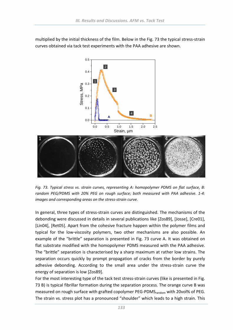
III. Results and Discussions. AFM vs. Tack Test
133
multiplied by the initial thickness of the film. Below in the Fig. 73 the typical stress‐strain
curves obtained via tack test experiments with the PAA adhesive are shown.
0.0 0.5 1.0 1.5 2.0 2.5
0.0
0.1
0.2
0.3
0.4
0.5
3
2
1 S
tres
s, M
Pa
Strain, µm
A B 4
1 2 3 4
Fig. 73. Typical stress vs. strain curves, representing A: homopolymer PDMS on flat surface, B:
random PEG/PDMS with 20% PEG on rough surface; both measured with PAA adhesive. 1‐4:
images and corresponding areas on the stress‐strain curve.
In general, three types of stress‐strain curves are distinguished. The mechanisms of the
debonding were discussed in details in several publications like [Zos89], [Josse], [Cre01],
[Lin04], [Ret05]. Apart from the cohesive fracture happen within the polymer films and
typical for the low‐viscosity polymers, two other mechanisms are also possible. An
example of the “brittle” separation is presented in Fig. 73 curve A. It was obtained on
flat substrate modified with the homopolymer PDMS measured with the PAA adhesive.
The “brittle” separation is characterised by a sharp maximum at rather low strains. The
separation occurs quickly by prompt propagation of cracks from the border by purely
adhesive debonding. According to the small area under the stress‐strain curve the
energy of separation is low [Zos89].
For the most interesting type of the tack test stress‐strain curves (like is presented in Fig.
73 B) is typical fibrillar formation during the separation process. The orange curve B was
measured on rough surface with grafted copolymer PEG‐PDMSrandom with 20vol% of PEG.
The strain vs. stress plot has a pronounced “shoulder” which leads to a high strain. This
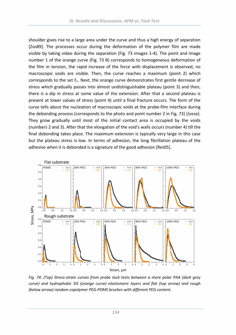
III. Results and Discussions. AFM vs. Tack Test
134
shoulder gives rise to a large area under the curve and thus a high energy of separation
[Zos89]. The processes occur during the deformation of the polymer film are made
visible by taking video during the separation (Fig. 73 images 1‐4). The point and image
number 1 of the orange curve (Fig. 73 B) corresponds to homogeneous deformation of
the film in tension, the rapid increase of the force with displacement is observed, no
macroscopic voids are visible. Then, the curve reaches a maximum (point 2) which
corresponds to the set Fc. Next, the orange curve demonstrates first gentle decrease of
stress which gradually passes into almost undistinguishable plateau (point 3) and then,
there is a dip in stress at some value of the extension. After that a second plateau is
present at lower values of stress (point 4) until a final fracture occurs. The form of the
curve tells about the nucleation of macroscopic voids at the probe‐film interface during
the debonding process (corresponds to the photo and point number 2 in Fig. 73) [Josse].
They grow gradually until most of the initial contact area is occupied by the voids
(numbers 2 and 3). After that the elongation of the void’s walls occurs (number 4) till the
final debonding takes place. The maximum extension is typically very large in this case
but the plateau stress is low. In terms of adhesion, the long fibrillation plateau of the
adhesive when it is debonded is a signature of the good adhesion [Ret05].
0.0 0.5 1.0 1.5
0.0
0.1
0.2
0.3
0.4
0.5
0.6 PAA SIS
PDMS
0.0 0.5 1.0 1.5
PAA SIS
20% PEG
0.0 0.5 1.0 1.5
PAA SIS
50% PEG
0.0 0.5 1.0 1.5
PAA SIS
80% PEG
0.0 0.5 1.0 1.5
PAA SIS
100% PEG
Flat substrate
0 1 2 3 4
0.0
0.1
0.2
0.3
0.4
0.5
0.6 PAA SIS
PDMS
0 1 2 3 4
PAA SIS
20% PEG
0 1 2 3 4
PAA SIS
50% PEG
0 1 2 3 4
PAA SIS
80% PEG
0 1 2 3 4
PAA SIS
100% PEG
Rough substrate
Stress, M
Pa
Strain, µm
Fig. 74. (Top) Stress‐strain curves from probe tack tests between a more polar PAA (dark grey
curve) and hydrophobic SIS (orange curve) elastomeric layers and flat (top arrow) and rough
(below arrow) random copolymer PEG‐PDMS brushes with different PEG content.
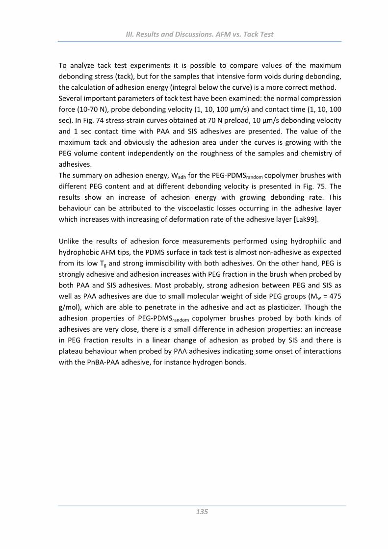
III. Results and Discussions. AFM vs. Tack Test
135
To analyze tack test experiments it is possible to compare values of the maximum
debonding stress (tack), but for the samples that intensive form voids during debonding,
the calculation of adhesion energy (integral below the curve) is a more correct method.
Several important parameters of tack test have been examined: the normal compression
force (10‐70 N), probe debonding velocity (1, 10, 100 µm/s) and contact time (1, 10, 100
sec). In Fig. 74 stress‐strain curves obtained at 70 N preload, 10 µm/s debonding velocity
and 1 sec contact time with PAA and SIS adhesives are presented. The value of the
maximum tack and obviously the adhesion area under the curves is growing with the
PEG volume content independently on the roughness of the samples and chemistry of
adhesives.
The summary on adhesion energy, Wadh for the PEG‐PDMSrandom copolymer brushes with
different PEG content and at different debonding velocity is presented in Fig. 75. The
results show an increase of adhesion energy with growing debonding rate. This
behaviour can be attributed to the viscoelastic losses occurring in the adhesive layer
which increases with increasing of deformation rate of the adhesive layer [Lak99].
Unlike the results of adhesion force measurements performed using hydrophilic and
hydrophobic AFM tips, the PDMS surface in tack test is almost non‐adhesive as expected
from its low Tg and strong immiscibility with both adhesives. On the other hand, PEG is
strongly adhesive and adhesion increases with PEG fraction in the brush when probed by
both PAA and SIS adhesives. Most probably, strong adhesion between PEG and SIS as
well as PAA adhesives are due to small molecular weight of side PEG groups (Mw = 475
g/mol), which are able to penetrate in the adhesive and act as plasticizer. Though the
adhesion properties of PEG‐PDMSrandom copolymer brushes probed by both kinds of
adhesives are very close, there is a small difference in adhesion properties: an increase
in PEG fraction results in a linear change of adhesion as probed by SIS and there is
plateau behaviour when probed by PAA adhesives indicating some onset of interactions
with the PnBA‐PAA adhesive, for instance hydrogen bonds.
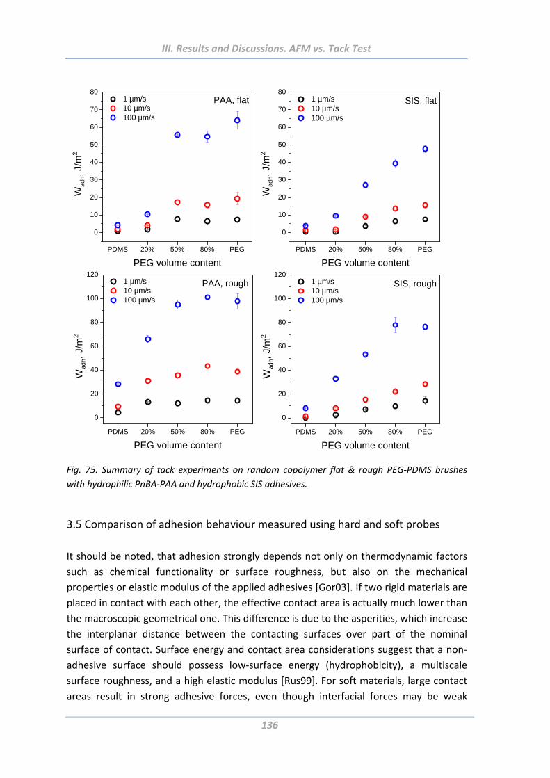
III. Results and Discussions. AFM vs. Tack Test
136
PDMS 20% 50% 80% PEG
0
10
20
30
40
50
60
70
80 1 µm/s 10 µm/s 100 µm/s
Wad
h, J
/m2
PEG volume content
PAA, flat
PDMS 20% 50% 80% PEG
0
10
20
30
40
50
60
70
80 1 µm/s 10 µm/s 100 µm/s
Wad
h, J
/m2
PEG volume content
SIS, flat
PDMS 20% 50% 80% PEG
0
20
40
60
80
100
120 1 µm/s 10 µm/s 100 µm/s
Wad
h, J
/m2
PEG volume content
PAA, rough
PDMS 20% 50% 80% PEG
0
20
40
60
80
100
120 1 µm/s 10 µm/s 100 µm/s
Wad
h, J
/m2
PEG volume content
SIS, rough
Fig. 75. Summary of tack experiments on random copolymer flat & rough PEG‐PDMS brushes
with hydrophilic PnBA‐PAA and hydrophobic SIS adhesives.
3.5 Comparison of adhesion behaviour measured using hard and soft probes
It should be noted, that adhesion strongly depends not only on thermodynamic factors
such as chemical functionality or surface roughness, but also on the mechanical
properties or elastic modulus of the applied adhesives [Gor03]. If two rigid materials are
placed in contact with each other, the effective contact area is actually much lower than
the macroscopic geometrical one. This difference is due to the asperities, which increase
the interplanar distance between the contacting surfaces over part of the nominal
surface of contact. Surface energy and contact area considerations suggest that a non‐
adhesive surface should possess low‐surface energy (hydrophobicity), a multiscale
surface roughness, and a high elastic modulus [Rus99]. For soft materials, large contact
areas result in strong adhesive forces, even though interfacial forces may be weak
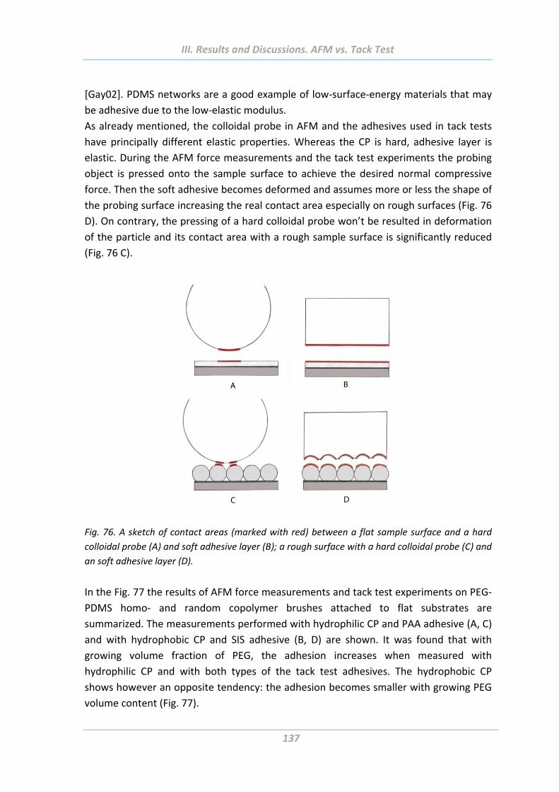
III. Results and Discussions. AFM vs. Tack Test
137
[Gay02]. PDMS networks are a good example of low‐surface‐energy materials that may
be adhesive due to the low‐elastic modulus.
As already mentioned, the colloidal probe in AFM and the adhesives used in tack tests
have principally different elastic properties. Whereas the CP is hard, adhesive layer is
elastic. During the AFM force measurements and the tack test experiments the probing
object is pressed onto the sample surface to achieve the desired normal compressive
force. Then the soft adhesive becomes deformed and assumes more or less the shape of
the probing surface increasing the real contact area especially on rough surfaces (Fig. 76
D). On contrary, the pressing of a hard colloidal probe won’t be resulted in deformation
of the particle and its contact area with a rough sample surface is significantly reduced
(Fig. 76 C).
Fig. 76. A sketch of contact areas (marked with red) between a flat sample surface and a hard
colloidal probe (A) and soft adhesive layer (B); a rough surface with a hard colloidal probe (C) and
an soft adhesive layer (D).
In the Fig. 77 the results of AFM force measurements and tack test experiments on PEG‐
PDMS homo‐ and random copolymer brushes attached to flat substrates are
summarized. The measurements performed with hydrophilic CP and PAA adhesive (A, C)
and with hydrophobic CP and SIS adhesive (B, D) are shown. It was found that with
growing volume fraction of PEG, the adhesion increases when measured with
hydrophilic CP and with both types of the tack test adhesives. The hydrophobic CP
shows however an opposite tendency: the adhesion becomes smaller with growing PEG
volume content (Fig. 77).
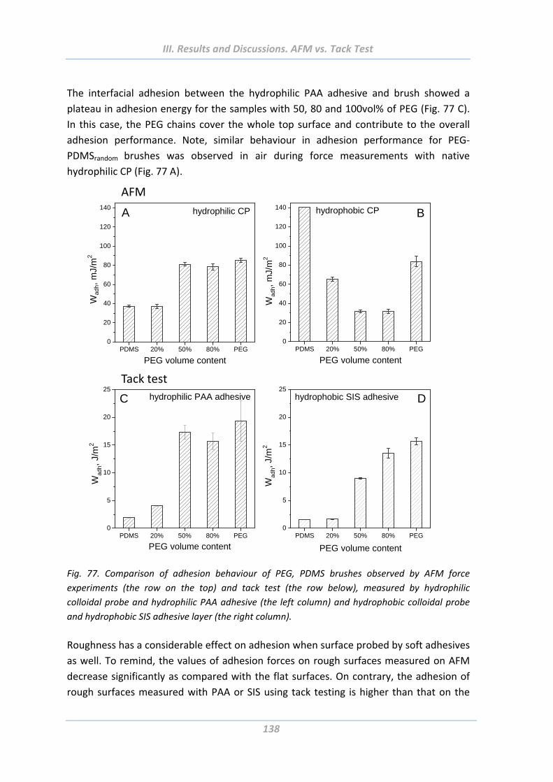
III. Results and Discussions. AFM vs. Tack Test
138
The interfacial adhesion between the hydrophilic PAA adhesive and brush showed a
plateau in adhesion energy for the samples with 50, 80 and 100vol% of PEG (Fig. 77 C).
In this case, the PEG chains cover the whole top surface and contribute to the overall
adhesion performance. Note, similar behaviour in adhesion performance for PEG‐
PDMSrandom brushes was observed in air during force measurements with native
hydrophilic CP (Fig. 77 A).
PDMS 20% 50% 80% PEG0
20
40
60
80
100
120
140 hydrophobic CP
Wad
h, m
J/m
2
PEG volume content
B
PDMS 20% 50% 80% PEG0
20
40
60
80
100
120
140
Wad
h,
mJ/
m2
PEG volume content
hydrophilic CPA
AFM
PDMS 20% 50% 80% PEG0
5
10
15
20
25
Wad
h, J
/m2
PEG volume content
hydrophobic SIS adhesive D
PDMS 20% 50% 80% PEG0
5
10
15
20
25
Wad
h, J
/m2
PEG volume content
hydrophilic PAA adhesiveC
Tack test
Fig. 77. Comparison of adhesion behaviour of PEG, PDMS brushes observed by AFM force
experiments (the row on the top) and tack test (the row below), measured by hydrophilic
colloidal probe and hydrophilic PAA adhesive (the left column) and hydrophobic colloidal probe
and hydrophobic SIS adhesive layer (the right column).
Roughness has a considerable effect on adhesion when surface probed by soft adhesives
as well. To remind, the values of adhesion forces on rough surfaces measured on AFM
decrease significantly as compared with the flat surfaces. On contrary, the adhesion of
rough surfaces measured with PAA or SIS using tack testing is higher than that on the
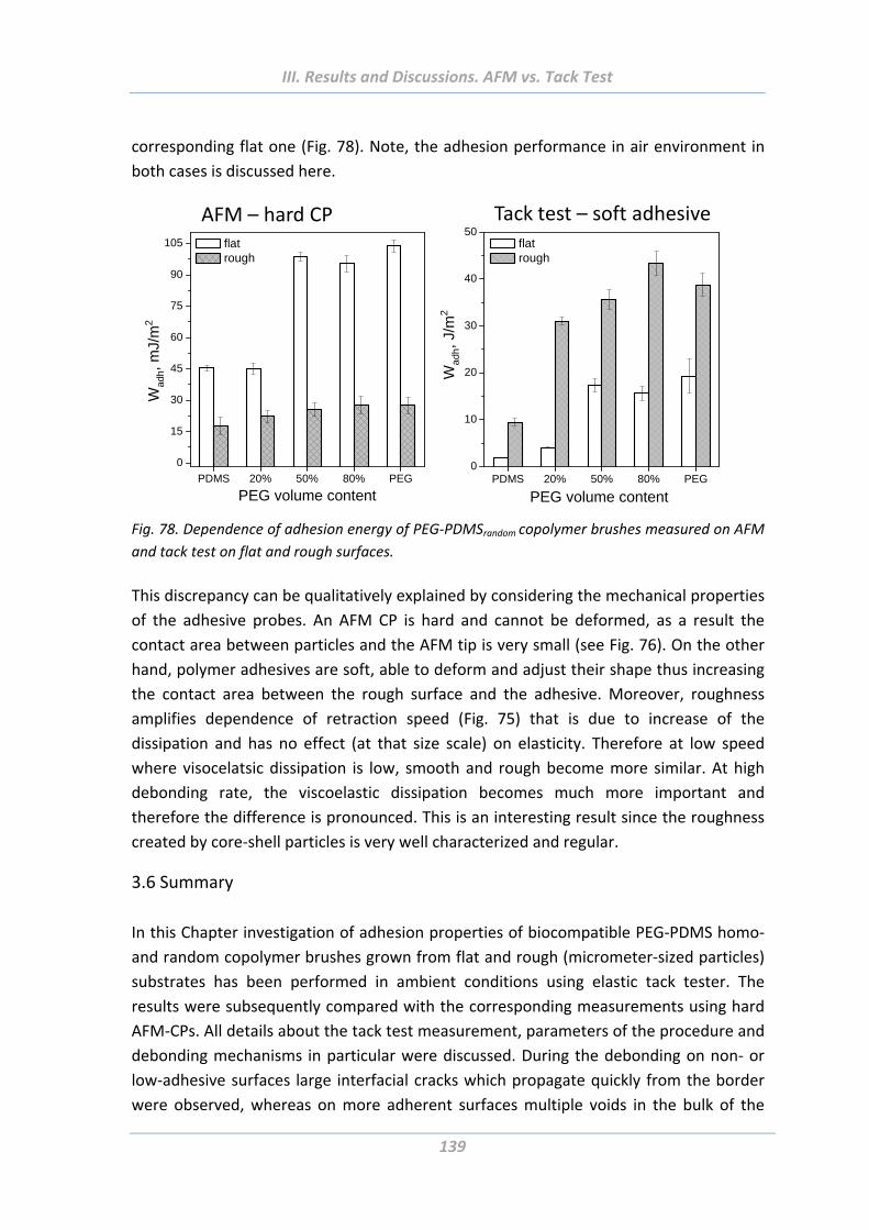
III. Results and Discussions. AFM vs. Tack Test
139
corresponding flat one (Fig. 78). Note, the adhesion performance in air environment in
both cases is discussed here.
PDMS 20% 50% 80% PEG0
10
20
30
40
50 flat rough
PEG volume content
Wad
h, J
/m2
PDMS 20% 50% 80% PEG
0
15
30
45
60
75
90
105
Wad
h, m
J/m
2
PEG volume content
flat rough
AFM – hard CP Tack test – soft adhesive
Fig. 78. Dependence of adhesion energy of PEG‐PDMSrandom copolymer brushes measured on AFM
and tack test on flat and rough surfaces.
This discrepancy can be qualitatively explained by considering the mechanical properties
of the adhesive probes. An AFM CP is hard and cannot be deformed, as a result the
contact area between particles and the AFM tip is very small (see Fig. 76). On the other
hand, polymer adhesives are soft, able to deform and adjust their shape thus increasing
the contact area between the rough surface and the adhesive. Moreover, roughness
amplifies dependence of retraction speed (Fig. 75) that is due to increase of the
dissipation and has no effect (at that size scale) on elasticity. Therefore at low speed
where visocelatsic dissipation is low, smooth and rough become more similar. At high
debonding rate, the viscoelastic dissipation becomes much more important and
therefore the difference is pronounced. This is an interesting result since the roughness
created by core‐shell particles is very well characterized and regular.
3.6 Summary
In this Chapter investigation of adhesion properties of biocompatible PEG‐PDMS homo‐
and random copolymer brushes grown from flat and rough (micrometer‐sized particles)
substrates has been performed in ambient conditions using elastic tack tester. The
results were subsequently compared with the corresponding measurements using hard
AFM‐CPs. All details about the tack test measurement, parameters of the procedure and
debonding mechanisms in particular were discussed. During the debonding on non‐ or
low‐adhesive surfaces large interfacial cracks which propagate quickly from the border
were observed, whereas on more adherent surfaces multiple voids in the bulk of the
III. Results and Discussions. AFM vs. Tack Test
140
adhesive layer which grow slowly and lead to a fibrillar structure (Fig. 73) were detected
[Josse].
It was shown, that the elasticity of a probing surface influences strongly the adhesion
properties of investigated systems. Soft and compliant PAA and SIS adhesive layers used
for tack tests facilitate larger contact area and thus tackiness on hard rough surfaces
than that on the flat ones. The measurements on rough surfaces with a hard colloidal
probe on AFM resulted in dramatically reduced contact area and thus much lower values
of adhesion forces than it was measured on flat surfaces.
The increase of adhesion forces in air with growing PEG fraction in PEG‐PDMS copolymer
brushes measured with hydrophilic CP was confirmed also with the tack test. This
tendency remains the same on flat and on rough surface if measured with both
hydrophobic SIS and hydrophilic PAA adhesives. However the evolution of adhesion
forces with growing PEG content measured with a hydrophobic CP had an opposite
character.
IV. Summary
141
IV. Summary
The aim of the thesis was preparation of smart functional materials with switchable and
adaptive adhesion properties. The polymer brushes were successfully synthesised using
ATRP procedure on flat and rough (made of 1 µm large spherical particles) substrates.
Important parameters were varied and controlled to prepare desired samples of
different chemical and architectural structure.
For control of quality and characterisation of the fabricated samples several advanced
analytical tools were used. Ellipsometric measurements provided information about the
thickness in dry state and degree of swelling of polymer layers in water. Investigation of
wetting properties was done using ADSA on thermoresponsive polymer brushes and
contact angle measurements on PEG‐PDMS solvent responsive copolymers. Surface
charges were studied using Zeta‐potential measurements. Surface morphology and its
rearrangements upon external stimuli were registered on topography images using
AFM.
All‐embracing investigation of switchable adhesion properties under the influence of
external stimuli (temperature, dry/wet state) was performed by means of AFM force
measurements. Theory about adhesion phenomenon points out three main factors that
influence the strength of adhesion between any two surfaces: molecular interactions at
interface, mechanical properties of adhesives, and contact area. Numerous parameters
that influence these three factors were thoroughly investigated in this work.
1) Molecular interactions at interface of two objects are determined by their chemical
functionality. The investigated polymers are stimuli‐responsive wherefore the influence
of surrounding media on these interactions has to be taken into account as well.
Diversity of chemical functionality at interface was achieved through numerous ways:
‐ Three types of thermoresponsive polymer brushes have been investigated that
differ in their chemical composition and structure of polymer chains (density of
side chains);
‐ Chemical variety of the solvent‐responsive systems was provided with different
ratio of PEG and PDMS components comprising the copolymer brushes and
through different architecture of polymer chains: random or block copolymers;
‐ Different thickness of polymer layers;
‐ Adhesion properties were influenced by temperature of the surrounding
aqueous media (thermoresponsive polymer brushes), and by dry/wet conditions
(solvent‐responsive polymer brushes);
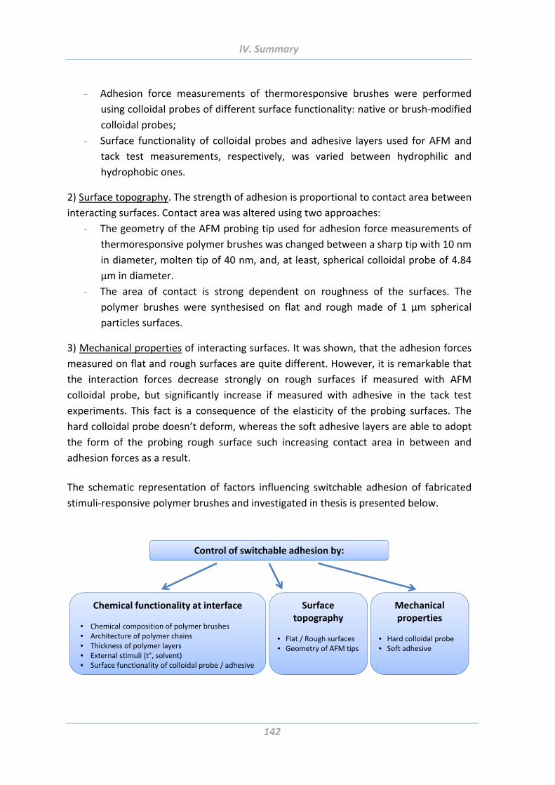
IV. Summary
142
‐ Adhesion force measurements of thermoresponsive brushes were performed
using colloidal probes of different surface functionality: native or brush‐modified
colloidal probes;
‐ Surface functionality of colloidal probes and adhesive layers used for AFM and
tack test measurements, respectively, was varied between hydrophilic and
hydrophobic ones.
2) Surface topography. The strength of adhesion is proportional to contact area between
interacting surfaces. Contact area was altered using two approaches:
‐ The geometry of the AFM probing tip used for adhesion force measurements of
thermoresponsive polymer brushes was changed between a sharp tip with 10 nm
in diameter, molten tip of 40 nm, and, at least, spherical colloidal probe of 4.84
µm in diameter.
‐ The area of contact is strong dependent on roughness of the surfaces. The
polymer brushes were synthesised on flat and rough made of 1 µm spherical
particles surfaces.
3) Mechanical properties of interacting surfaces. It was shown, that the adhesion forces
measured on flat and rough surfaces are quite different. However, it is remarkable that
the interaction forces decrease strongly on rough surfaces if measured with AFM
colloidal probe, but significantly increase if measured with adhesive in the tack test
experiments. This fact is a consequence of the elasticity of the probing surfaces. The
hard colloidal probe doesn’t deform, whereas the soft adhesive layers are able to adopt
the form of the probing rough surface such increasing contact area in between and
adhesion forces as a result.
The schematic representation of factors influencing switchable adhesion of fabricated
stimuli‐responsive polymer brushes and investigated in thesis is presented below.
Control of switchable adhesion by:
Surface topography
• Flat / Rough surfaces• Geometry of AFM tips
Mechanical properties
• Hard colloidal probe• Soft adhesive
Chemical functionality at interface
• Chemical composition of polymer brushes• Architecture of polymer chains• Thickness of polymer layers• External stimuli (t°, solvent)• Surface functionality of colloidal probe / adhesive
V.Outlook
143
V. Outlook
The interest for “smart” stimuli‐responsive materials has been growing during the last
decades because of increasing demand for materials able to respond to external stimuli
with dramatic and predictable structural changes. Such materials are broadening the
horizons of applications in numerous areas from medicine and sportswear to food
packaging and the aerospace and automotive sectors. Prepared from thermo‐, light‐,
pH‐ and other responsive polymer systems, the commercial possibilities of these smart
materials are literally endless.
The results achieved in this work show new possibilities for expanding field of stimuli‐
responsive materials. Since the investigated polymeric systems are biocompatible and
biodegradable they are of a great interest for biomedical applications. Moreover, the
temperature‐responsive polymers presented in the work undergo their switching of
adhesion in the body‐temperature region. They could be used, for example, for
biosensors, adhesion of proteins or tissue engineering. The solvent‐responsive systems
with low adhesion forces shown here could be promising as wound dressing materials to
prevent the tissue from damages caused while detaching of a strong‐adherent material.
On the other hand, the PEG‐PDMS systems with high adhesion could be useful for
surgery where highly biocompatible, strong and flexible surgical glue is of great need.
Current surgical glues and sealants are either protein‐based, in which case they exhibit
low bond strength, and are in some cases derived from blood products, with associated
risk of viral or prion contamination. Very strong synthetic glues are toxic to living tissues
and form rigid, nonporous films that can hinder wound healing [Gra05].
There are several ideas concerning the next steps in continuation of the subject of this
work. Firstly, it could be interesting to manufacture systems comprised of polymers
responsive to another than temperature or solvent stimuli or even responsive to several
stimuli. This could lead to smart systems where the responsiveness to a combination of
stimuli allows for fine‐tuning adhesion strengths.
Secondly, as it was shown in this work, the architecture of polymer chains play often
crucial role in adhesion performance. That is why the synthesis of copolymers with
varying chain architecture could yield materials with desired properties.
Moreover, the combination of stimuli‐responsive surface coating with a patterned
surface responsive as well to external stimuli would possibly lead to very interesting
materials with fascinating switchable properties. Often used principal of maximization
V.Outlook
144
and minimization of the contact area would be combined with adhesion and non‐
adhesion properties of the polymer coating [Syn12].
Since the thin polymer brushes are quite vulnerable to scratches and other damages
their switching behaviour undergoes gradual degradation with time and switching
cycles. Therefore a promising idea was suggested to manufacture mechanically stable
stimuli‐responsive coatings made of thick (hundred nanometres to microns) block
copolymer brushes [SY125]. The particular interest to the block copolymer brushes
known from literature [Elb99], [Zha00a], [Goh01], [Boy02], [Lud03], [Boy04], [Lei04],
[Fus05], [Tok05], [Nak06], [Sai08], is explained by their ability to reversibly change the
surface properties via mobility of the block segments on the topmost polymer layer
upon treatment with selective solvents. Utilization of such thick “nanostructured mixed
polymer networks” as “smart” adhesives will significantly improve their lifetime because
of a “self‐repairing” effect. In general, in such multicomponent systems composed of
heterogeneous polymers, the lower‐surface‐energy component is located on the
surface. Being scratched the high‐surface‐energy component becomes bare that is
energetically unfavourable. Therefore, the low‐surface‐energy component will remove
to fill this scratch and recover the integrity of the low‐energy surface layer [Rus02].
Besides the scratch‐resistant surfaces, another possible fields of application of the
multicomponent block copolymers include nanotechnology, in biomedicine for
controlled release of bioactive molecules, for development of dispersants and stabilizers
for pigments in aqueous and organic medium and many others [Rie03], [Sai08], [Lud03].
For the most part in this work the investigations of adhesion behaviour were performed
via AFM in order to learn about fundamental processes occurring on nano‐ and
micrometer scales. It would however make sense to carry out the tack test experiments
to study also the processes on macrometer scale. It was shown here by way of example
on PEG‐PDMS random copolymer brushes and is believed to be useful to apply regularly
on the systems developing for marketable products.
Biological solutions developed by nature over millions of years continue to inspire and
give ideas for rational design and construction of multifunctional manmade “smart”
materials. However there is still a long way before synthetic materials of comparable
with natural complexity would be achieved. Therefore, further interdisciplinary
cooperation of scientists and engineers is inevitably to reach the aim of such smart
materials.
VI. References
145
VI. References
[Ada97] W. A. Adamson, A. P. Gast, “Physical Chemistry of Surfaces”, Wiley‐Interscience
publication, 1997 [AFM05] “A practical guide to SPM Scanning Probe Microscopy”, Veeco, 2005
[Aki04] Y. Akiyama, A. Kikuchi, M. Yamato, T. Okano, “Ultrathin Poly(N‐isopropylacrylamide) Grafted Layer on Polystyrene Surfaces for Cell Adhesion/Detachment Control”, Langmuir 2004, 20, 5506‐5511
[Aks07] B. Aksak, M. P. Murphy, M. Sitti, “Adhesion of Biologically Inspired Vertical and Angled Polymer Microfiber Arrays” Langmuir 2007, 23, 3322
[Ala05] C. de las Heras Alarcon, S. Pennadam, C. Alexander “Stimuli responsive polymers for biomedical applications”, Chem. Soc. Rev., 2005, 34, 276–285
[Ale77] S. Alexander, “Adsorption of chain molecules with a polar head; A scaling description”, J. Phys. (Paris) 1977, 38, 983.
[Arz03] E. Arzt, S. Gorb, R. Spolenak, “From micro to nano contacts in biological attachment devices”. Proc. Natl. Acad. Sci. U.S.A. 2003, 100 (19), 10603‐ 10606.
[Ass06] S. Assemi, J. Nalaskowski, W. P. Johnson, “Direct force measurements between carboxylate‐modified latex microspheres and glass using atomic force microscopy”Colloids Surf., A 2006, 286, 70‐77
[Aut00] K. Autumn, Y. A. Liang, S. T. Hsieh, W. Zesch, W. P. Chan, T. W. Kenny, R. Fearing, R. J. Full, “Adhesive force of a single gecko foot‐hair”, Nature, Vol 405, 8 June 2000
[Aut02] K. Autumn, A. M. Peattie, “Mechanisms of Adhesion in Geckos”, Integr. Comp. Biol. 2002, 42, 1081
[Aut08] K. Autumn, N. Gravish, “Gecko adhesion: evolutionary nanotechnology” Phil. Trans. R. Soc. A 2008, 366, 1575–1590
[Awa09] F. Awaja, M. Gilbert, G. Kelly, B. Fox, P. J. Pigram “Adhesion of polymers”, Progress in Polymer Science, 34, 2009, 948–968.
[Ayr07] N. Ayres, S. G. Boyes, W. J. Brittain “Stimuli‐responsive polyelectrolyte polymer brushes prepared via ATRP”, Langmuir 2007, 23, 182‐189
[Azz99] R. M. A. Azzam, “Ellipsometry”, North‐Holland, Amsterdam, http://www.mhprofessional.com/handbookofoptics/pdf/Handbook_of_Optics_vol1_ch16.pdf, November 2012
[Bar07] W. Jon. P. Barnes, “Biomimetic Solutions to Sticky Problems”, Science Vol 318, 12 October 2007
[Barn04] L. Barner, C. Li, X. Hao, M. N. Stenzel, C. Barner‐Kowollok, T. P. Davis, “Synthesis of Core‐Shell Poly(Divinylbenzene) Microspheres via Reversible Addition Fragmentation Chain Transfer Graft Polymerization of Styrene”, J Polym Sci Part A Polym Chem 2004, 42, 5067‐76
[Baw09] P. Bawa, V. Pillay, Y. E Choonara, Lisa C du Toit, „Stimuli‐responsive polymers and their applications in drug delivery“ Biomed. Mater. 4 2009, 022001
[Bel02] C. Bellmann, Ch. Klinger, A. Opfermann, F. Böhme, H.‐J.P. Adler, “Evaluation of surface modification by electrokinetic measurements”, Prog. Org. Coat. 2002, 44, 93
[Bel07] C. Bellmann, A. Synytska, A. Caspari, A. Drechsler, K. Grundke, “Electrokinetic investigation of surfactant adsorption” J. Colloid Interface Sci., 2007, 309, 225–230
[Ber10] S. Berger, “Multifunctional Stimuli‐Responsive Hybrid Colloids: Synthesis and Applications”, dissertation 2010
VI. References
146
[Bhu06] B. Bhushan, Y. C. Jung, “Micro‐ and nanoscale characterization of hydrophobic and hydrophilic leaf Surfaces”, Nanotechnology 2006, 17, 2758–2772
[Bia04] H. Bianco‐Peled, S. Gryc, “Binding of Amino Acids to “Smart” Sorbents: Where Does Hydrophobicity Come into Play?”, Langmuir 2004, 20, 169‐174
[Bian05] K. Bian, M. F. Cunningham, "Part A: Polymer Chemistry", Journal of Polymer Science 2005, 43, 10, 2145‐2154
[Bie02] M. Biesalski, “Synthesis and swelling behaviour of a weak polyacid brush”, J. Chem. Phys. 2002, Vol. 117, No. 10
[Big00] S. Biggs, M. Habgooda, G. J. Jameson, Yao‐de Yan, “Aggregate structures formed via a bridging flocculation mechanism”, Chemical Engineering Journal, 80, 2000, 13–22
[Bil10] G. Bilic, C. Brubaker, P. B. Messersmith, "AJOG‐DOPA fetal membran repair", American Journal of Obstetrics & Gynaecology 2010, 85.e1‐85.e9
[Bin86] G. Binnig, C. F. Quate, Ch. Gerber, „Atomic Force Microscope“, Phys. Rev. Lett. 1986, 56, 930
[Bit10] E. Bittrich, “Design of new responsive materials based on functional polymer brushes“, dissertation 2010
[Boc08] V. Bocharova, “Electrically Conductive Low Dimensional Nanostructures: Synthesis, Characterisation and Application”, dissertation 2008
[Boe10] L. F. Boesel, C. Greiner, E. Arzt, A. del Campo “Gecko‐inspired surfaces: A path to strong and reversible dry adhesives”, Adv. Mater. 2010, 22, 2125–2137
[Boy01] J. M. Boyne, E. J. Millan, I. Webster “Peeling performance of a novel light switchable pressure‐sensitive adhesive” International Journal of Adhesion & Adhesives 21 2001, 49‐53
[Boy02] S. G. Boyes, W. J. Brittain, X. Weng, S. Z. D. Cheng, “Synthesis, Characterization, and Properties of ABA Type Triblock Copolymer Brushes of Styrene and Methyl Acrylate Prepared by Atom Transfer Radical Polymerization”, Macromolecules 2002, 35, 4960‐4967
[Boy04] S. G. Boyes, A. M. Granville, M. Baum, B. Akgun, B. K. Mirous, W. J. Brittain, “Polymer brushes–surface immobilized polymers”, Surface Science 570, 2004, 1–12
[Bri90] D. Briggs, M. P. Seah, "Practical Surface Analysis by Auger and X‐ray Photoelectron Spectroscopy", Wiley, Chinchester, 1990, pp 202‐255.
[Bro09] W. R. Browne, B. L. Feringa, “Light switching of molecules on surfaces”, Ann. Rev. Phys. Chem. 2009, 60, 407–28
[Bun08] C. B. Bunker, “Reversible switching of interfacial interactions”, Materials Science and Engineering R 62, 2008, 157‐173
[Bur05] Z. Burton, B. Bhushan, "Hydrophobicity, Adhesion, and Friction Properties of Nanopatterned Polymers and Scale Dependence for Micro‐ and Nanoelectromechanical Systems", Nano Lett. 2005, 5, 1607‐1613
[But05] H.‐J. Butt, B. Cappella, M. Kappl, “Force measurements with the atomic force microscope: Technique, interpretation and applications”, Surface Science Reports, 59, 2005, 1–152
[But91] H.‐J. Butt «Measuring electrostatic, van der Waals, and hydration forces in electrolyte solutions with an atomic force microscope», Biophys. J. 1991, 60, 1438‐1444
[But93] H.‐J. Butt, P. Siedle, K. Seifert, K. Fendler, T. Seeger, E. Bamberg, A. L. Weisenhorn, K. Goldie, A. Engel, “Scan speed limit in atomic force microscopy”, J. Microsc. 1993, 169, 75
VI. References
147
[Cam08] A. del Campo, E. Arzt, “Fabrication Approaches for Generating Complex Micro‐ and Nanopatterns on Polymeric Surfaces”, Chem. Rev. 2008, 108, 911‐945
[Can05] H. E. Canavan, X. Cheng, D. J. Graham, B. D. Ratner, D. G. Castner, “Surface characterization of the extracellular matrix remaining after cell detachment from a thermoresponsive polymer”, Langmuir 2005, 21, 1949‐1955
[Car96] A. Carré, J.‐C. Gastel, M. E. R. Shanahan, “Viscoelastic effects in the spreading of liquids”, Letters to Nature 1996, vol. 379
[Cas44] A. B. D. Cassie, S. Baxter, “Wettability of porous surfaces”, Trans. Faraday Soc. 1944, 40546
[Cha81] R.‐J. Chang, A. N. Gent, “Effect of Interfacial Bonding on the Strength of Adhesion of Elastomers. I. Self‐Adhesion”, Journal of Polymer Science: Polymer Physics Edition 1981, Vol. 19, 1619‐1633
[Chi01] R. A. Chivers, “Easy removal of pressure sensitive adhesives for skin applications”, International Journal of Adhesion & Adhesives 21 2001, 381–388
[Cho03] K. Cho, J. H. Cho, S. Yoon, C. E. Park, J.‐C. Lee, S.‐H. Han, K.‐B. Lee, J. Koo, "Switchable Tack in Side‐Chain Liquid Crystalline Polymers", Macromolecules 2003, 36, 2009‐2014.
[Cla93] R. Clarke, A. Larson, E. E. Schmitt and S. P. Bitler, Adhes. Age, 1993, 39–41
[Cle93] J.P. Cleveland, S. Manne, D. Bocek, P.K. Hansma, “A nondestructive method for determining the spring constant of cantilevers for scanning force microscopy”, Rev. Sci. Instrum. 64 1993, 403
[Cli05] C. A. Clifford, M. P. Seah, "The determination of atomic force microscope cantilever spring constants via dimensional methods for nanomechanical analysis", Nanotechnology 2005, 16, 1666–1680
[cmu] http://www.cmu.edu/maty/materials/, August 2012
[Cre01] C. Creton, J. Hooker, “Bulk and Interfacial Contributions to the Debonding Mechanisms of Soft Adhesives: Extension to Large Strains”, Langmuir 2001, 17, 4948‐4954
[Cre02] C. Creton, P. Fabre, “Adhesion science and engineering”, A. V. Pocius ed.; Elsevier, 2002; Vol. 1, chp. 14.
[Cre03a] C. Creton “Pressure‐Sensitive Adhesives: An Introductory Course”, MRS Bulletin, June 2003
[Cre03b] C. Creton and E. Papon, Guest Editors, “Materials Science of Adhesives: How to Bond Things Together”, MRS Bulletin, June 2003
[Cre96] C. Creton, L. Leibler, “How does tack depend on time of contact and contact pressure?” J. Polym. Sci. B 1996, 34, 545–554.
[Cre99] G. de Crevoisier, P. Fabre, J.‐M. Corpart, L. Leibler “Switchable Tackiness and Wettability of a Liquid Crystalline Polymer” Science 1999 Vol 285
[Cro05] A. J. Crosby, M. Hageman, A. Duncan, “Controlling Polymer Adhesion with “Pancakes”, Langmuir 2005, 21, 11738
[Cun03] D. Cunliffe, C. de las Heras Alarcón, V. Peters, J. R. Smith, C. Alexander, “Thermoresponsive Surface‐Grafted Poly(N‐isopropylacrylamide) Copolymers: Effect of Phase Transitions on Protein and Bacterial Attachment”, Langmuir 2003, 19, 2888–2899
[Dah69] C. A. Dahlquist, "Pressure‐sensitive adhesives", In R. L. Patrick (ed.), "Treatise on adhesion and adhesives" M. Dekker, New York 1969, Vol. 2, pp. 219–260. .
[Del05] F. W. Delrio, M. P. de Boer, J. A. Knapp, E. D. Reedy, P. J. Clews, M. L. Dunn, ““The role of van der Waals forces in adhesion of micromachined surfaces“, Nat. Mater. 2005, 4, 629–634.
VI. References
148
[Dem10] K. Demidenok, “Polyelectrolyte nanostructures formed in the moving contact line: fabrication, characterization and application“, dissertation 2010
[Der34] B. V. Derjaguin, “Theory of the adhesion of small particles”, Kolloid‐Z., 1934, 69, 155
[Der75] B. Derjaguin, Muller, Toporov, “Effect of contact deformations on the adhesion of particles”, J. Colloid. Interf. Sci. 314‐326, 1975
[Dic91] E. Dickinson, V. B. Galazka, “Bridging flocculation induced by competitive adsorption: implications for emulsion stability”, J. Chem. Soc. Faraday Trans., 1991, 87(7), 963‐969
[Dre10] [Dre12]
A. Drechsler, A. Synytska, P. Uhlmann, M. M. Elmahdy, M. Stamm and F. Kremer, “Interaction Forces between Microsized Silica Particles and Weak Polyelectrolyte Brushes at Varying pH and Salt Concentration”, Langmuir 2010, 26, 6400–6410 A. Drechsler, A. Synytska, P. Uhlmann, M. Stamm, F. Kremer, „Tuning the adhesion of silica microparticles to a poly(2‐vinyl pyridine) brush – an AFM force measurement study“, Langmuir, 2012 submitted
[Duc91] W. A. Ducker, T. J. Senden, R. M. Pashley, “Direct measurement of colloidal forces using an atomic force microscope”, Nature 1991, 353, 239‐241.
[Duc92] W. A. Ducker, T. J. Senden, R. M. Pashley, “Measurement of Forces in Liquids Using a Force Microscope”, Langmuir 1992, 8, 1831‐1836.
[Dut00] [Duv11]
V. Dutschk „Oberflächenkräfte und ihr Beitrag zu Adhäsion und Haftung in glasfaserverstäkten Thermoplasten“, dissertation 2000 J. F. L. Duval, D. Kü ner, C. Werner, R. Zimmermann, “Electrohydrodynamics of Soft Polyelectrolyte Multilayers: Point of Zero‐Streaming Current”, Langmuir 2011, 27, (17), 10739‐10752.
[Eda05] J. Edahiro, K. Sumaru, Y. Tada, K. Ohi, T. Takagi, M. Kameda, T. Shinbo, T. Kanamori, Y. Yoshimi, “In situ control of cell adhesion using photoresponsive culture surface”, Biomacromolecules, 2005, 6, 970
[Elb99] H. Elbs, K. Fukunaga, R. Stadler, G. Sauer, R. Magerle, G. Krausch, „Microdomain Morphology of Thin ABC Triblock Copolymer Films”, Macromolecules 1999, 32,1204‐1211
[Elm09a] M. M. Elmahdy, A. Drechsler, C. Gutsche, A. Synytska, P. Uhlmann, F. Kremer and M. Stamm, “Forces between Blank Surfaces As Measured by the Colloidal Probe Technique and by Optical Tweezers ‐ A Comparison”, Langmuir 2009, 25, 12894–12898
[Fag12] A. Faghihnejad, H. Zeng, “Hydrophobic interactions between polymer surfaces: using polystyrene as a model system”, Soft Matter, 2012, 8, 2746–2759
[Fis01] H. Fischer, “The Persistent Radical Effect: A Principle for Selective Radical Reactions and Living Radical Polymerizations”, Chemical Reviews 2001, 101, 3581‐3610
[Fis02] K. Fischer, M. Schmidt, „Solvent‐induced length variation of cylindrical brushes“, Macromol Rapid Commun 2001, 22, 787–91.
[Fou95] G. Fourche, “An Overview of the Basic Aspects of Polymer Adhesion. Part I: Fundamentals”, Polymer Engineering and Science, June 1995, Vol. 35, No. 12
[Für05] R. Fürstner, W. Barthlott, C. Neinhuis, P. Walzel, “Wetting and Self‐Cleaning Properties of Artificial Superhydrophobic Surfaces“, Langmuir 2005, 21, 956‐961
[Fus05] C. A. Fustin, V. Abetz, J. F. Gohy, “Classification of ABC. Triblock terpolymer micelles: A personal outlook”, Eur Phys J E Soft Matter 2005, 16, 291
[Gay02] C. Gay, “Stickiness ‐ Some Fundamentals of Adhesion”, Integr. Comp. Biol. 2002, 42,1123–1126
VI. References
149
[Gay03] C. Gay, "Some Fundamentals of Adhesion in Synthetic Adhesives", Biofouling 2003, 19, 53‐57.
[Gay99] C. Gay, L. Leibler, "Theory of Tackiness", Phys. Rev. Lett. 1999, 82, 936‐939
[Gen00] J. Genzer, K. Efimenko, “Creating Long‐Lived Superhydrophobic Polymer Surfaces Through Mechanically Assembled Monolayers”, Science 290 2000, 2130
[Gen01] P. G. de Gennes, "Ultradivided matter", Nature 2001, 412, 385–1385
[Gen72] A. N. Gent, J. Schultz “Effect of Wetting Liquids on the Strength of Adhesion of Viscoelastic Materia“, J. Adhesion, 1972, Vol. 3, pp. 281‐294
[Gen80] P. G. de Gennes, “Conformations of Polymers Attached to an Interface” Macromolecules 1980, 13, 1069‐1075
[Geo06] P. M. George, D. A. LaVan, J. A. Burdick, C. Y. Chen, E. Liang and R. Langer, “Electrically Controlled Drug Delivery from Biotin‐Doped Conductive Polypyrrole”, Adv. Mater., 2006, 18, 577
[Ger02] M. Gerard, A. Chaubey, B. D. Malhotra, „Application of conducting polymers to biosensors“, Biosensors & Bioelectronics 17 2002, 345–359
[Gib96] C. T. Gibson, G. S. Watson, S. Myhra, “Determination of the spring constants of probes for force microscopy/spectroscopy”, Nanotechnology 1996, 7, 259.
[Gil04] E. S. Gil, S. M. Hudson, “Stimuli‐reponsive polymers and their bioconjugates”, Progress in Polymer Science 2004, 29, 1173‐1222
[Gla04] N. J. Glassmaker, A. Jagota, C. Y. Hui, J. Kim, “Design of biomimetic fibrillar interfaces: 1. Making contact”, J. R. Soc. Interface 2004, 1, 23.
[Goh01] J. F. Gohy, N. Willet, S. Varshney,J. X. Zhang, R. Jerome, “Core‐Shell‐Corona Micelles with a Responsive Shell”, Angew. Chem., Int. Ed. 2001, 40, 3214–3216.
[Goh05] J. F. Gohy, “Block Copolymers II”, 2005 ‐ Springer
[Gol07] D. S. Golovko, R. Munoz‐Espi, G. Wegner, “Interaction between Poly(styrene‐acrylic acid) Latex Nanoparticles and Zinc Oxide Surfaces”, Langmuir 2007, 23, 3566‐3569
[Goo04] D. Goodman, J. N. Kizhakkedathu, D. E. Brooks, „Molecular Weight and Polydispersity Estimation of Adsorbing Polymer Brushes by Atomic Force Microscopy“, Langmuir 2004, 20, 3297‐3303
[Gor05] E. Gorb, K. Haas, A. Henrich, S. Enders, N. Barbakadze, S. Gorb, "Composite structure of the crystalline epicuticular wax layer of the slippery zone in the pitchers of the carnivorous plant Nepenthes alata and its effect on insect attachment", J Exp Biol 2005, 208, 4651‐4662
[Gor05] G. Gorodyska, “Generation and Characterisation of Nanostructures from Single Adsorbed Polyelectrolyte Molecules”, dissertation 2005
[Gra04] A. C. R. Grayson, R. S. Shawgo, A. M. Johnson, N. T. Flynn, Y. W. Li, M. J. Cima, R. Langer, “A BioMEMS Review: MEMS Technology for Physiologically Integrated Devices”, Proc. IEEE 2004, 92, 6–21
[Gra05] L. D. Graham et al. ”Characterization of a Protein‐based Adhesive Elastomer Secreted by the Australian Frog Notaden bennetti”, Biomacromolecules 2005, 6, 3300‐3312
[Gre07] C. Greiner, A. del Campo, E. Arzt, "Adhesion of Bioinspired Micropatterned Surfaces: Effects of Pillar Radius, Aspect Ratio, and Preload", Langmuir 2007, 23, 3495‐3502
[Gre66] J. A. Greenwood, J. B. P. Williamson, "Contact of nominally flat surfaces", Proc. R. Soc. London, 1966, Ser. A 295, 300–319.
[Hal10] A. Halperin, E. B. Zhulina, “Atomic Force Microscopy of Polymer Brushes: Colloidal versus Sharp Tips”, Langmuir, 2010, 26, 8933–8940
VI. References
150
[Haz99] J. L. Hazel, V. V. Tsukruk, “Spring constants of composite ceramic/gold cantilevers for scanning probe microscopy”, Thin Solid Films 1999, 339, 249‐257
[Hem11] S. Hempel, „Aufklärung der Wechselwirkung von Abrasivteilchen einer Poliersuspension mit Oberflächen mittels direkter Kraft‐ und rheologischer Untersuchungen“, 2011
[Hig04] A. Higuchi, A. Hamamura, Y. Shindo, H. Kitamura, B. O. Yoon, T. Mori, T. Uyama, A. Umezawa, “Photon‐Modulated Changes of Cell Attachments on poly(spiropyran‐co‐methyl methacrylate) membranes biomacromolecules”, Biomacromolecules 2004, 5, 1770‐1774
[Hou03] N. Houbenov, S. Minko, M. Stamm, "Mixed polyelectrolyte brush from oppositely charged polymers for switching of surface charge and composition in aqueous environment", Macromolecules 2003, 36, 5897‐5901.
[Hou05] N. Houbenov, "Adsorption and Grafting of Polyelectrolytes at Solid‐Liquid Interfaces", dissertation 2005
[How07] J. A. Howarter, J. P. Youngblood, “Self‐Cleaning and Anti‐Fog Surfaces via Stimuli‐Responsive Polymer Brushes”, Adv. Mater. 2007, 19, 3838–3843
[Hsu07] H.‐P. Hsu, W. Paul, K. Binder, "Simulation of Copolymer Bottle‐Brushes", Macromol. Symp. 2007, 252, 58–67
[Hub03] D. L. Huber, R. P. Manginell, M. A. Samara, B. I. Kim, B. C. Bunker, “Programmed Adsorption and Release of Proteins in a Microfluidic Device”, Science 301, 2003, 352
[Hüt02] G. Hüttl, V. Klemm, R. Popp, F. Simon, E. Müller, “Tailored colloidal AFM probes and their TEM investigation”, Surface and Interface Analysis 2002, 33, 50 – 53
[Hut05] J. L. Hutter, “Calibration of AFM Cantilevers”, 2005 [Hut93] J. L. Hutter, J. Bechhoefer, “Calibration of atomic‐force microscope tips”, Rev. Sci.
Instrum. 1993, 64, 403 [Hüt97] G. Hüttl, D. Beyer, E. Müller, „Investigation of electrical double layers on SiO2
surfaces by means of force vs. distance measurements“, Surf. Interface Anal. 25 1997, 543‐547
[Hyu04] J. Hyun, W.‐K. Lee, N. Nath, A. Chilkoti, S. Zauscher, "Capture and Release of Proteins on the Nanoscale by Stimuli‐Responsive Elastin‐Like, Polypeptide “Switches”, J. Am. Chem. Soc. 2004, 126, 7330–7335.
[Ill02] L. Illum, “Nasal drug delivery: new developments and strategies”, DDT Vol. 7, No. 23 December 2002
[Ion03] L. Ionov, S. Minko, M. Stamm, J. F. Gohy, R. Jerome, A. Scholl, "Reversible chemical patterning on stimuli‐responsive polymer film: Environment‐responsive lithography", J. Am. Chem. Soc. 2003, 125, 8302‐8306
[Ion05] L. Ionov, “Synthesis and characterisation of patterned and gradient polymer brush surfaces“, disseration 2005
[Ion06a] L. Ionov, S. Sapra, A. Synytska, A. L. Rogach, M. Stamm, S. Diez, "Fast and spatially resolved environmental probing using stimuli‐responsive polymer layers and fluorescent nanocrystals", Advanced Materials 2006, 18, (11), 1453
[Ion06b] L. Ionov, N. Houbenov, A. Sidorenko, M. Stamm, S. Minko, "Smart microfluidic channels", Advanced Functional Materials 2006, 16, (9), 1153‐1160
[Ion08] L. Ionov, A. Synytska and S. Diez, “Temperature‐Induced Size‐Control of Bioactive Surface Patterns”, Adv. Funct. Mater. 2008, 18, 1501–1508
[Iru08] J. Iruthayaraj, "Poly(Ethylene Oxide) Based Bottle‐Brush Polymers and their Interaction with the Anionic Surfactant Sodium Dodecyl Sulphate: Solution and Interfacial Properties", dissertation 2008
VI. References
151
[Ish03] K. Ishizu, N. Sawada, J. Satoh and A. Sogabe, “Architecture and surfactant behavior of amphiphilic prototype copolymer brushes”, J. Mater. Sci. Lett. 2003, 22, 1219
[Isr01] D. Leckband, J. Israelachvili, „Intermolecular forces in biology”, Quarterly Reviews of Biophysics 2001, 34, 2, pp. 105–267
[Isr82] J. Israelachvili, R. Pashley, “The hydrophobic interactions is long range, decaying exponentially with distance”, Nature 1982, 300‐25,
[Isr92] Israelachvili, J. “Intermolecular and surface forces”, 2nd ed., Academic Press: London and New York 1992
[Jab94] E. Jabbari, N. A. Perras, “Polymer‐Polymer lnterdiffusion and Adhesion”, J.M.S‐Rev. Macromol. Chem. Phys. 1994 C34(2), 205‐241
[Jak05] W. Jakubowski, K. Matyjaszewski, “Activator Generated by Electron Transfer for Atom Transfer Radical Polymerization”, Macromolecules 2005, 38, 4139‐4146.
[Jeo06] H. E. Jeong, S. H. Lee, J. K. Kim, K. Y. Suh, “Nanoengineered Multiscale Hierarchical Structures with Tailored Wetting Properties”, Langmuir 2006, 22, 1640
[Jeo10] H. E. Jeong, M. K. Kwak and K. Y. Suh, “Stretchable, Adhesion‐Tunable Dry Adhesive by Surface Wrinkling”, Langmuir, 2010, 26, 2223–2226
[Jia06] H. Jiang, S. Kelch, A. Lendlein, „Polymers Move in Response to Light“. Adv. Mater. 2006, 18, 1471–1475.
[Joh64] R. E. Johnson, R. H. Dettre, “Contact Angle Hysteresis”, Adv. Chem. Ser. 43112, 1964
[Jon02] R. Jones, H. M. Pollock, J. A. S. Cleaver, C. S. Hodges, "Adhesion forces between glass and silicon surfaces in air studied by AFM: effects of relative humidity, particle size, roughness, and surface treatment", Langmuir 2002, 18, 8045 ‐ 8055
[Jon04] J. de Jong, G. ten Brinke, "Conformational Aspects and Intramolecular Phase Separation of Alternating Copolymacromonomers: A Computer Simulation Study", Macromol. Theory Simul. 2004, 13, 318–327
[Jon07] A. M. Jonas, K. Glinel, R. Oren, B. Nysten, W. T. S. Huck, “Thermo‐Responsive Polymer Brushes with Tunable Collapse Temperatures in the Physiological Range”, Macromolecules 2007, 40, 4403–4405
[Josse] G. Josse, C. Creton, M. Dorget, “Probe tack test of pressure‐sensitive‐adhesives on low energy surfaces”, http://www.espci.fr/usr/creton/proceedings/C‐28.pdf , november 2012
[Jul03] D. Julthongpiput, Y.‐H. Lin, J. Teng, E. R. Zubarev, V. V. Tsukruk, “Y‐Shaped Amphiphilic Brushes with Switchable Micellar Surface Structures”, J. Am. Chem. Soc. 2003, 125, 15912‐15921.
[Kam10] M. Kamperman, E. Kroner, A. del Campo, R. M. McMeeking, E. Arzt, “Functional Adhesive Surfaces with ‘‘Gecko’’ Effect: The Concept of Contact Splitting”, Adv. Eng. Mater., 2010, 12, 335–348
[Kap02] M. Kappl, H.‐J. Butt, "The Colloidal Probe Technique and its Application to Adhesion Force Measurements", Part. Part. Syst. Charact. 2002, 19, 129‐143.
[Kato95] M. Kato, M. Kamigaito, M. Sawamoto, T. Higashimura, “Polymerization of Methyl Methacrylate with the Carbon Tetrachloridel / Dichlorotris‐(triphenylphosphine)ruthedum(II) / Methylaluminum Bis(2,6‐di‐tert‐butylphenoxideI) Itiating System: Possibility of Living Radical Polymerization” Macromolecules 1995, 28, 1721–1723
[Kes10] S. Kessel, S. Schmidt, R. Müller, E. Wischerhoff, A. Laschewsky, J.‐F. Lutz, K. Uhlig, A. Lankenau, C. Duschl, A. Fery, „Thermoresp. PEG‐based polymer layers: surface characterization with AFM force measurements“, Langmuir 2010, 26(5), 3462
VI. References
152
[Kho01] S. Khongtong, G. S. Ferguson, “Integration of Bulk and Interfacial Properties in a Polymeric System: Rubber Elasticity at a Polybutadiene/Water Interface”, J.Am.Chem.Soc. 2001, 123, 3588‐3594
[Kho02] Khongtong, S.; Ferguson, G. S. “A Smart Adhesive Joint: Entropic Control of Adhesion at a Polymer/Metal Interface”, J. Am. Chem. Soc. 2002, 124, 7254‐7255.
[Kim06] S. Kim, M. Sitti, “Biologically inspired polymer microfibers with spatulate tips as repeatable fibrillar adhesives”, Appl. Phys. Lett. 2006, 89, 261911
[Kim10] S. Kim, J. Wu, A. Carlson, S. H. Jin, A. Kovalsky, P. Glass, Z. Liu, N. Ahmed, S. L. Elgan, W. Chen, P. M. Ferreira, M. Sitti, Y. Huang and J. A. Rogers, “Microstructured elastomeric surfaces with reversible adhesion and examples of their use in deterministic assembly by transfer printing”, Proc. Natl. Acad. Sci. U. S. A., 2010, 107, 17095–17100.
[Kin80] A. J. Kinloch “The science of adhesion Part 1”, Journal of Materials Science 15 1980, 2141 ‐2166
[Kin87] A. J. Kinloch, Adhesion and Adhesives: Science and Technology, Chapman and Hall, 1987
[Kod12] T. E. Kodger and J. Sprakel, Thermosensitive Molecular, Colloidal, and Bulk
Interactions Using a Simple Surfactant“, Adv. Funct. Mater. 2012
[kruss] http://www.kruss.de/en/theory/measurements/contact‐angle/measurement‐contact‐angle.html, August 2012
[Kus07] T. S. Kustandi, V. D. Samper,W. S. Ng, A. S. Chong, H. Gao,“Fabrication of a gecko‐like hierarchical fibril array using a bonded porous alumina template”, J. Micromech. Microeng. 2007, 17, N75.
[Lah03] J. Lahann, S. Mitragotri, T.‐N. Tran, H. Kaido, J. Sundaram, I. S. Choi, S. Hoffer, G. A. Somorjai, R. Langer, “A Reversibly Switching Surface”, Science 2003, 299, 371
[Lak67] G. J. Lake; A. G.Thomas, “The strength of highly elastic materials”, Proc. Roy. Soc. A 1967, 300, 108–119
[Lak98] Lakrout, H., PhD. Thesis, Université Paris, 7, 1998.
[Lak99] H. Lakrout, P. Sergot, C. Creton, “Direct observation of cavitation and fibrillation in a probe tack experiment on model acrylic pressure‐ sensitive‐adhesives”, J. Adhesion, 1999, Vol. 69, pp. 307‐359
[Lam07] M. Lamblet, E. Verneuil, T. Vilmin, A. Buguin, P. Solberzan, L. Léger, “Adhesion enhancement through micropatterning at polydimethylsiloxane‐acrylic adhesive interfaces”, Langmuir 2007, 23, 6966
[Lan04] R. Langer, D. A. Tirrell, “Designing materials for biology and medicine”, Nature, Vol 428 2004
[Lan98] R. Langer, "Drug delivery and targeting", Nature 392 (Suppl.) 1998, 5–10
[Lee07] H. Lee, B. P. Lee P. B. Messersmith, “A reversible wet/dry adhesive inspired by mussels and geckos”, Nature 2007, Vol 448, 19
[Lee08] J. Lee, C. Majidi, B. Schubert, and R. Fearing, “Sliding induced adhesion of stiff polymer microfiber arrays: 1. Macroscale behaviour,'' Journal of the Royal Society, Interface, J. R. Soc. Interface 2008, 5, 835–844
[Lee10] H. Lee, K. Matyjaszewski, “Stimuli‐responsive molecular brushes”, Progress in Polymer Science 35 2010, 24–44
[Lei04] L. C. Lei, J. F. Gohy, N. Willet, J. X. Zhang, S. Varshney, R. Jerome, “Tuning of the Morphology of Core‐Shell‐Corona Micelles in Water. I. Transition from Sphere to Cylinder”, Macromolecules 2004, 37, 1089–1094
VI. References
153
[Lei05] F. L. Leite, P. S. P. Herrmann, „Application of AFS to studies of adhesion phenomena: a review”, Atomic Force Microscopy in Adhesion Studies, pp. 3‐43, Eds. J. Drelich and K.L. Mittal, VSP, Leiden‐Boston 2005
[Len05] A. Lendlein, H. Jiang, O. Jünger, R. Langer, „Light‐induced shape‐memory polymers“, Nature 2005, 434, 879–882.
[Lev98] R. Levicky, N. Koneripalli, M. Tirrell, S. K. Satija, "Stratification in bidisperse polymer brushes from neutron reflectivity", Macromolecules 1998, 31, (8), 2616‐2621.
[Li08] D. Li, M. G. Huson, L. D. Graham, “Proteinaceous Adhesive Secretions From Insects, and in Particular the Egg Attachment Glue of Opodiphthera sp. Moths”, Archives of Insect Biochemistry and Physiology 2008, 69, 85–105
[Li93] Y. Q. Li, N. J. Tho, J. Pan, A. A. Garcia, S. M. Lindsay, "Direct Measurement of Interaction Forces between Colloidal Particles Using the Scanning Force Microscope", Langmuir 1993, 9, 637
[Lin04] A. Lindner, T. Maevis, R. Brummer, B. Lühmann, and C. Creton, "Subcritical Failure of Soft Acrylic Adhesives under Tensile Stress“, Langmuir 2004, 20, 9156‐9169
[Lin99] S.‐Y. Lin, K.‐S. Chen, L. Run‐Chu, “Thermal micro ATR/FT‐IR spectroscopic system for quantitative study of the molecular structure of poly(N‐isopropylacrylamide) in water”, Polymer 40 1999, 2619–2624
[Liu12] [Löt97]
K. Liu, L. Jiang, “Bio‐Inspired Selt‐Cleaning Surfaces“, Annu. Rev. Mater. Res. 2012, 42, 231–63 J. C. Lötters, W. Olthuis, P. H. Veltink, P. Bergveld, “The mechanical properties of the rubber elastic polymer polydimethylsiloxane for sensor applications”, J. Micromech. Microeng. 7, 1997, 145–147
[Lud03] S. Ludwigs, A. Böker, A. Voronov, N. Rehse, R. Magerle, G. Krausch “Self‐assembly of functional nanostructures from ABC triblock copolymers”, Nature Materials, Vol 2, November 2003
[lum11] http://www.luminaadhesives.com/, August 2012 [Lut08] J.‐F. Lutz, “Polymerization of Oligo(Ethylene Glycol) (Meth)Acrylates: Toward New
Generations of Smart Biocompatible Materials”, J. Polym. Sci. Part A: Polym. Chem., 2008, Vol. 46 3459‐3470,
[Luz04] I. Luzinov, S. Minko, V. V. Tsukruk, “Adaptive and responsive surfaces through controlled reorganization of interfacial polymer layers”, Prog. Polym. Sci. 29 2004, 635–698
[Luz08] I. Luzinov, S. Minko, V. V. Tsukruk, „Responsive brush layers: from tailored gradients to reversibly assembled nanoparticles“, Soft Matter 2008, 4, 714–725.
[Ma06] M. Ma, R. M. Hill, “Superhydrophobic surfaces”, Current Opinion in Colloid & Interface Science 11 2006, 193–202
[Mal10] I. B. Malham and L. Bureau, “Density Effects on Collapse, Compression, and Adhesion of Thermoresponsive Polymer Brushes”, Langmuir 2010, 26, 4762–4768
[Manual03] SPM Training Notebook, Manual, 2003
[Mat95] K. Matyjaszewski, S. Gaynor, J.‐S. Wang, “Controlled Radical Polymerizations: The Use of Alkyl Iodides in Degenerative Transfer”, Macromolecules 1995, 28, 2093‐2095
[Mat98] K. Matyjaszewski. “Inner Sphere and Outer Sphere Electron Transfer Reactions in Atom Transfer Radical Polymerization”, Macromol. Symp. 1998, 134, 105‐118
[Mat07] K. Matyjaszewski, H. Dong, W. Jakubowski, J. Pietrasik, A. Kusumo, “Grafting from Surfaces for “Everyone”: ARGET ATRP in the Presence of Air”, Langmuir 2007, 23, 4528‐4531
VI. References
154
[Men08] P. Mendez, “Stimuli‐responsive surfaces for bio‐applications”, Chem. Soc. Rev., 2008, 37, 2512–2529
[Men09] S. Mendez, B. P. Andrzejewski, H. E. Canavan, D. J. Keller, J. D. McCoy,G. P. Lopez, J. G. Curro, “Understanding the force‐vs‐distance profiles of terminally attached poly(N‐isopropyl acrylamide) thin films”, Langmuir 2009, 25 (18), p.10624–10632
[Mes02] P. B. Lee, J. L. Dalsin, P. B. Messersmith, “Synthesis and Gelation of DOPA‐Modified Poly(ethylene glycol) Hydrogels”, Biomacromolecules 2002, 3, 1038‐1047
[Mes07] H. Lee, S. M. Dellatore, W. M. Miller, P. B. Messersmith, “Mussel‐inspired surface chemistry for multifunctional coatings”, Science, 19 Oct. 2007 VOL 318
[Mil87] L. L. Miller, Q. X. Zhou, “Poly(N‐methylpyrrolylium) Poly(styrenesulfonate). A Conductive, Electrically Switchable Cation Exchanger That Cathodically Binds and Anodically Releases Dopamine”, Macromolecules, 1987, 20, 1594
[Min02a] S. Minko, S. Patil, V. Datsyuk, F. Simon, K. J. Eichhorn, M. Motornov, D. Usov, I. Tokarev, M. Stamm, “Synthesis of adaptive polymer brushes via "grafting to" approach from melt”, Langmuir 2002, 18, 289‐296.
[Min02b] Minko, S.; Muller, M.; Usov, D.; Scholl, A.; Froeck, C.; Stamm, M. Lateral versus perpendicular segregation in mixed polymer brushes Phys. Rev. Lett. 2002, 88, 35502.
[Min03a] S. Minko, M. Muller, M. Motornov, M. Nitschke, K. Grundke, M. Stamm, "Two‐level structured self‐adaptive surfaces with reversibly tunable properties", Journal of the American Chemical Society 2003, 125, (13), 3896‐3900.
[Min03b] S. Minko, I. Luzinov, V. Luchnikov, M. Muller, S. Patil, M. Stamm, "Bidisperse Mixed Brushes: Synthesis and Study of Segregation in Selective Solvent", Macromolecules 2003, 36, 7268‐7279.
[Min05] K. Min, H. Gao, K. Matyjaszewski, “Preparation of Homopolymers and Block Copolymers in Miniemulsion by ATRP Using Activators Generated by Electron Transfer (AGET)”, J. Am. Chem. Soc. 2005, 127, 3825‐3830.
[Min05a] W. Ming, D. Wu, R. van Benthem, G. de With, “Superhydrophobic films from raspberry‐like particles”, Nano Lett 2005, 5: 2298–301
[Min06] S. Minko, "Responsive polymer brushes", Polymer Reviews 2006, 46, (4), 397‐420.
[Mit08] S. Mitragotri, “Recent Developments in Needle‐Free Drug Delivery”, The bridge, U.S. Frontiers of Engineering Symposium, 2008
[Moo64] J. C. Moore, “Gel Permeation Chromatography. I. A New Method for Molecular Weight Distribution of High Polymers“, Journal of polymer science: part A Vol. 2, 1964, pp. 835443
[Mor99] S. Mori, H. G. Barth, “Size exclusion chromatography” Springer, 1999
[Mot07] M. Motornov, R. Sheparovych, I. Tokarev, Y. Roiter, S. Minko, "Nonwettable thin films from hybrid polymer brushes can be hydrophilic", Langmuir 2007, 23, (1), 13‐19
[Mot08] M. Motornov, J. Zhou, M. Pita, V. Gopishetty, I. Tokarev, E. Katz, S. Minko, "Chemical transformers" from nanoparticle ensembles operated with logic", Nano Letters 2008, 8, (9), 2993‐2997.
[Moy05] S. Moya, O. Azzaroni, T. Farhan, V. L. Osborne, W. T. S. Huck, „Locking and Unlocking of Polyelectrolyte Brushes: Toward the Fabrication of Chemically Controlled Nanoactuators“, Angew. Chem. Int. Ed. 2005, 44, 4578–4581
[Mrk03] W.‐S. Yeo, M. Mrksich, “Self‐Assembled monolayers that transduce enzymatic activities to electrical signals”, Angew. Chem. Int. Ed. 2003, 42, 3121 – 3124
[Multimode04] MultiMode SPM Instruction Manual, 2004
VI. References
155
[Nad10] N. Nadermann, J. Ning, A. Jagota and C. Y. Hui, “Active Switching of Adhesion in a Film‐Terminated Fibrillar Structure”, Langmuir, 2010, 26, 15464–15471
[Nak06] K. Nakashima, P. Bahadur, “Aggregation of water‐soluble block copolymers in aqueous solutions: Recent trends”, Advances in Colloid and Interface Science 123– 126, 2006, 75–96
[Nan10] H. Nandivada, A. M. Ross, J. Lahann. ”Stimuli‐responsive monolayers for biotechnology”, Progress in Polymer Science 35, 2010, 141–154
[Nat02] N. Nath, A. Chilkoti, "Creating "Smart" surfaces using stimuli responsive polymers", Advanced Materials 2002, 14, (17), 1243
[Nat03] N. Nath, A. Chilkoti, “Fabrication of a Reversible Protein Array Directly from Cell Lysate Using a Stimuli‐Responsive Polypeptide” Anal. Chem. 2003, 75, 709‐715
[Neu07] D. Neugebauer, “Review Graft copolymers with poly(ethylene oxide) segments”, Polym. Int., 2007, 56, 1469–1498
[Nig04] R. Nigmatullin, R. Lovitt, C. Wright, M. Linder, T. Nakari‐Setälä, M. Gama, “Atomic force microscopy study of cellulose surface interaction controlled by cellulose binding domains”, Colloids Surf. B 35 2004, 125‐135
[Nor08] T. Northen, C. Greiner, E. Arzt, K. L. Turner, „A Gecko‐Inspired Reversible Adhesive“, Adv. Mater. 2008, 20, 1‐5
[Ori03] G. Orive, R. M. Hernández, A. R. Gascón, A. Domínguez‐Gil, J. L. Pedraz “Drug delivery in biotechnology: present and future”, Current Opinion in Biotechnology 2003, 14, 659–664
[Par11] D. Paretkar, M. Kamperman, A. S. Schneider, D. Martina, C. Creton, E. Arzt “Bioinspired pressure actuated adhesive system”, Materials Science and Engineering C 31, 2011, 1152–1159
[Par12] D. Paretkar, M. Kamperman, R. McMeeking, C. Creton, A. Lindner, A. Jagota and E. Arzt, in preparation., 2012
[Per01] B. N. J. Persson, E. Tosatti, “The effect of surface roughness on the adhesion of elastic solids” J. Chem. Phys., September 2001 Vol. 115, No. 12, 22
[Per04] A. Peressadko, S. N. Gorb, “When less is more: experimental evidence for tenacity enhancement by division of contact area“, J. Adhes. 2004, 80, 247.
[Pos05] W. Possart, “Adhesion, Current research and application”, WILEY‐VCH Verlag, Weinheim 2005
[Pru98] O. Prucker, J. Rühe, “Mechanism of Radical Chain Polymerizations Initiated by Azo Compounds Covalently Bound to the Surface of Spherical Particles”, Macromol.592 1998, 602‐613
[Que03] D. Quere, A. Lafuma, J. Bico, J. “Slippy and sticky microtextured solids”, Nanotechnology 2003, 14, 1109‐1112
[Rap92] [Raz10]
E. Raphael, P. G. de Gennes “Rubber‐rubber adhesion with connector molecules”, J. Phys. Chem. 1992, 96,4002‐4007 M. A. Raza, E. S. Kooij, A. v. Silfhout, B. Poelsema, “Superhydrophobic Surfaces by Anomalous Fluoroalkylsilane Self‐Assembly on Silica Nanosphere Arrays”, Langmuir 2010, 26(15), 12962–12972
[Red07] S. Reddy, E. Arzt, A. del Campo, "Bioinspired surfaces with switchable adhesion", Advanced Material, 2007, 19, (22), 3833
[Ret05] H. Retsos, G. Gorodyska, A. Kiriy, M. Stamm, C. Creton, “Adhesion between chemically heterogeneous switchable polymeric brushes and an elastomeric adhesive”, Langmuir 2005, 21, 7722‐7725
[Ret06] H. Retsos, A. Kiriy, V. Senkovskyy, M. Stamm, M. M. Feldstein, C. Creton, "Controlling Tack with Bicomponent Polymer Brushes", Advanced Materials 2006, 18, 2624‐2628.
VI. References
156
[Ret08] H. Retsos, D. Lee, M.‐Y. Lim, J.‐C. Lee, K. Char, C.Creton, “Temperature Stability of the Interfacial Structure between a Sulfonated Crystalline Alkyl Side‐Chain Polymer and a Soft Adhesive”, Langmuir 2008, 24, 10169‐10173
[Rie03] G. Riess, “Micellization of block copolymers”, Prog Polym Sci 2003, 28, 1107
[Rio97] O. I. del Rıo, A. W. Neumann, “Axisymmetric Drop Shape Analysis: Computational Methods for the Measurement of Interfacial Properties from the Shape and Dimensions of Pendant and Sessile Drops“, Journal of colloid and interface science 1997, 196, 136–147
[Rüh04] J. Rühe, M. Ballauff, M. Biesalski, P. Dziezok, F. Grohn, D. Johannsmann, N. Houbenov, N. Hugenberg, R. Konradi, S. Minko, M. Motornov, R. R. Netz, M. Schmidt, C. Seidel, M. Stamm, T. Stephan, D. Usov, H. N. Zhang, “Polyelectrolyte brushes”, 2004, Vol. 165, pp 79‐150
[Rus02] T. P. Russell, "Surface‐Responsive Materials", Science 2002, 297, 964‐967
[Rus99] T. P. Russel, H. C. Kim, “Tack – a Sticky Subject”, Science 20 August 1999, Vol. 285 no. 5431 pp. 1219‐1220
[Sad95] J. E. Sader, I. Larson, P. Mulvaney, L. R. White, “Method for the calibration of atomic force microscope cantilevers“, Rev. Sci. Instrum. 1995, 66, 3789.
[Sag06] J. Sagert, C. Sun, J. H. Waite, "Chemical subtleties of mussel and polychaete holdfasts", Smith AM, Callow JA, editors. Biological adhesives. Berlin: Springer 2006, p 125–143
[Sai08] N. Saito, C. Liu, T. P. Lodge, M. A. Hillmyer, “Multicompartment Micelles from Polyester‐Containing ABC Miktoarm Star Terpolymers”, Macromolecules, Vol. 41, No. 22, 2008
[Sartor] M. Sartor, “Dynamic light scattering", University of California San Diego
[Sch08] B. Schubert, J. Lee, C. Majidi, and R. Fearing, “Sliding induced adhesion of stiff polymer microfiber arrays: 2. Microscale behaviour,'' Journal of the Royal Society, Interface, J. R. Soc. Interface 2008, 5, 845–853
[Sch09] S. Schmidt, “Motility and Force Generation Based on the Dynamics of Actin Gels”, dissertation 2009
[Sen94] T. J. Senden and W. A. Ducker, "Experimental Determination of Spring Constants in Atomic Force Microscopy", Langmuir 1994,10, 1003
[Sha95] M. E. R. Shanahan A. Carré, “Viscoelastic Dissipation in Wetting and Adhesion Phenomena”, Langmuir 1995, 11, 1396‐1402
[She08] R. Sheparovych, M. Motornov and S. Minko, “Adapting Low‐Adhesive Thin Films from Mixed Polymer Brushes”, Langmuir, 2008, 24,13828–13832
[She09] R. Sheparovych, M. Motornov, S. Minko “Low Adhesive Surfaces that Adapt to Changing Environments“, Adv. Mater. 2009, 21, 1–5
[Shi04] J. Y. Shiu, C. W. Kuo, P. L. Chen, C. Y. Mou, “Fabrication of tunable superhydrophobic surfaces by nanosphere lithography”, Chem Mater 2004, 16, 561–4.
[Sid99] A. Sidorenko, S. Minko, K. Schenk‐Meuser, H. Duschner, M. Stamm, “Switching of polymer brushes”, Langmuir 1999, 15, 8349‐8355
[Sing03] D. A. Singleton, D. T. Nowlan III, N. Jahed, K. Matyjaszewski, “Isotope Effects and the Mechanism of Atom Transfer Radical Polymerization”, Macromolecules 2003, 36, 8609‐8616
[Siq95] D. F. Siqueira, K. Koehler and M. Stamm, “Structures at the Surface of Dry Thin Films of Grafted Copolymers”, Langmuir, 1995, 11, 3092–3096
VI. References
157
[Sit03] M. Sitti, R.S. Fearing, “Synthetic Gecko Foot‐Hair Micro/Nano‐Structures as Dry Adhesives”, Journal of adhesion science and technology 2003 vol. 18, no. 7, p. 1055‐1074
[Sku00] H. Skulason, C. D. Frisbie, “Rupture of Hydrophobic Microcontacts in Water: Correlation of Pull‐Off Force with AFM Tip Radius”, Langmuir, 2000, 16, 6294–6297
[Smo21] M. Smoluchowski, „Handbuch der Elektrizität und des Magnetismus“, Band II, Barth‐Verlag, Leipzig, 1921
[Soe03] T. Soeno, K. Inokuchi, S. Shiratori, Trans. Mater. Res. Soc. Jpn. 2003, 28, 1207
[Sog96] K. G. Soga, M. J. Zuckermann, H. Guo, “Binary Polymer Brush in a Solvent”, Macromolecules 1996, 29, 1998‐2005
[Spi07] [Spr10]
R. La Spina, M. R. Tomlinson, L. Ruiz‐Pérez, A. Chiche, S. Langridge, and M. Geoghegan, "Controlling network‐brush interactions to achieve switchable adhesion", Angew. Chem. Int. Ed. 2007, 46 6460‐3 E. Spruijt, M. A. Cohen Stuart, J. van der Gucht, “Dynamic Force Spectroscopy of Oppositely Charged Polyelectrolyte Brushes”, Macromolecules 2010, 43, 1543–1550
[Ste02] T. Stephan, S. Muth, M. Schmidt, „Shape Changes of Statistical Copolymacromonomers: From Wormlike Cylinders to Horseshoe‐ and Meanderlike Structures”, Macromolecules 2002, 35, 9857‐9860
[Stu10] M. A. Stuart, W. T. S. Huck, J. Genzer, M. Muller, C. Ober, M. Stamm, G. B. Sukhorukov, I. Szleifer, V. V. Tsukruk, M. Urban, F. Winnik, S. Zauscher, I. Luzinov, S. Minko, “Emerging applications of stimuli‐responsive polymer materials”, Nature Materials 2010, 9, (2), 101‐113
[Sun04] T. Sun, „Reversible switching between superhydrophilicity and superhydrophobicity“, Angew. Chem. Int. Ed. 2004, 43, 357 –360
[Sun05] T. Sun, L. Feng, X. Gao, L. Jiang, "Bioinspired Surfaces with Special Wettability", Acc. Chem. Res. 2005, 38, 644‐652
[Sve11] [Sve12]
E. Svetushkina, N. Puretskiy, L. Ionov, M. Stamm, A. Synytska, “A comparative study on switchable adhesion between thermoresponsive polymer brushes on flat and rough surfaces”, Soft Matter, 2011, 7, 5691–5696 A. Synytska, E. Svetushkina, D. Martina, C. Bellmann, F. Simon, M. Stamm, C. Creton, “Intelligent materials with tunable adhesion properties based on biocompatible comb‐like polymer brushes”, accepted to Langmuir, 2012
[SY125] A. Synytska, DFG project [Syn05] A. Synytska, "Einfluss chemischer und topographischer Inhomogenitäten auf die
Eigenschaften von Polymeroberflächen", 2005 [Syn06] A. Synytska, L. Ionov, V. Dutschk, S. Minko, K.‐J. Eichhorn, M. Stamm, K. Grundke,
“Regular Patterned Surfaces from Core‐Shell Particles. Preparation and Characterization”, Progr Colloid Polym Sci 2006, 132, 72‐81.
[Syn07] [Syn08]
A. Synytska, M. Stamm, S. Diez, L. Ionov, “Simple and Fast Method for the Fabrication of Switchable Bicomponent Micropatterned Polymer Surfaces”, Langmuir 2007, 23, 5205‐5209 A. Synytska, L. Ionov, V. Dutschk, M. Stamm, K. Grundke, “Wetting on Regularly Structured Surfaces from “Core‐Shell” Particles: Theoretical Predictions and Experimental Findings”, Langmuir 2008, 24, 11895‐11901
[Syn10] A. Synytska, E. Svetushkina, N. Puretskiy, G. Stoychev, S. Berger, L. Ionov, C. Bellmann, K. J. Eichhorn and M. Stamm, “Biocompatible polymeric materials with switchable adhesion properties”, Soft Matter, 2010, 6, 5907–5914.
[Syn12] M. Kamperman, A. Synytska, “Switchable adhesion by chemical functionality and topography”, J. Mater. Chem., 2012,22, 19390-19401
VI. References
158
[Sza98] D. Szabó,G. Szeghy, M.Zrínyi, “Shape Transition of Magnetic Field Sensitive Polymer Gels”, Macromolecules 31, 1998, 6541
[Tod07] S. J. Todd, D. Farrar, J. E. Gough, R. V. Ulijn, “Enzyme‐triggered cell attachment to hydrogel surfaces”, Soft Matter, 2007, 3, 547–550
[Tok04] [Tok05]
I. Tokareva, S. Minko, J. H. Fendler, E. Hutter, "Nanosensors based on responsive polymer brushes and gold nanoparticle enhanced transmission surface plasmon resonance spectroscopy", Journal of the American Chemical Society 2004, 126, (49), 15950‐15951. I. Tokarev, R. Krenek, Y. Burkov, D. Schmeisser, A. Sidorenko, S. Minko, M. Stamm, “Microphase Separation in Thin Films of Poly(styrene‐block‐4‐vinylpyridine) Copolymer‐2‐(4'‐Hydroxybenzeneazo)benzoic Acid Assembly”, Macromolecules 2005, 38, 507‐516.
[Tok09] I. Tokarev, S. Minko, „Multiresponsive, hierarchically structured membranes: new, challenging, biomimetic materials for biosensors, controlled release, biochemical gates, and nanoreactors“, Adv. Mater. 2009, 21, 241–247
[Tor02] M. Torres‐Lugo, M. Garcia, R. Record, N. A. Peppas, “pH‐sensitive hydrogels as gastrointestinal tract absorption enhancers: Transport mechanisms of salmon calcitonin and other model molecules using the Caco‐2 cell model”. Biotechnol. Progr. 18 2002, 612–616
[Tor05] G. W. Tormoen, J. Drelich, J. Nalaskowski, "A distribution of AFM pull‐off forces for glass microspheres on a symmetrically structured rough surface", Atomic force microscopy in adhesion studies, pp. 345‐364, Eds. J. Drelich and K.L. Mittal, VSP, Leiden‐Boston 2005
[Tsu01] K. Tsubaki, H. Kobayashi, J. Sato, K. Ishizu, “Dilute Solution Properties and Aggregation Behavior of Alternate Hetero‐arm Copolymer Brushes”, Journal of colloid and interface Science 2001, 241, 275‐279.
[Uli06] R. V. Ulijn, “Enzyme‐responsive materials: a new class of smart biomaterials”, J. Mater. Chem., 2006, 16, 2217–2225
[Uso04] D. Usov, „Switching of Surface Composition and Morphology of Binary Polymer Brushes”, dissertation 2004
[Vil08] A. Vilalta‐Clemente, K. Gloystein, based on the lecture of Prof. N. Frangis, "Principles of Atomic rinciples Force Microscopy (AFM)", Physics of Advanced Materials Winter School, 2008
[Vis06] Viswanathan, K.; Ozhalici, H.; Elkins, C. L.; Heisey, C.; Ward, T. C.; Long, T. E., “Multiple hydrogen bonding for reversible polymer surface adhesion“, Langmuir 2006, 22, 1099‐1105
[Vog10] M. J. Vogel, P. H. Steen, “Capillarity‐based switchable adhesion”, Proc. Natl. Acad. Sci. U. S. A., 2010, 107, 3377–3381.
[Wai02] J. H. Waite, "Adhesion a la moule", Integr Comp Biol., 2002 42, 1172–1180 [Wan95] J.‐S. Wang, K. Matyjaszewski, “Controlled/”Living” Radical Polymerization”
J.Am.Chem.Soc. 1995, 117, 5614‐5615 [Wen36] R. N. Wenzel, “Resistance of solid surfaces to wetting by water”, Ind. Eng. Chem.
1936, 28, 988 [Wer99] C. Werner, K.‐J. Eichhorn, K. Grundke, F. Simon, W. Grählert and H.‐J. Jacobasch,
“Insights on structural variations of protein adsorption layers on hydrophobic fluorohydrocarbon polymers gained by spectroscopic ellipsometry (part I)”, Colloids Surf., A, 1999, 156, 3–17
[Wis08] E. Wischerhoff, K. Uhlig, A. Lankenau, H. G. Borner, A. Laschewsky, C. Duschl and J. F. Lutz, “Controlled Cell Adhesion on PEG‐Based Switchable Surfaces”, Angew. Chem., Int. Ed. 2008, 47, 5666–5668
VI. References
159
[WSxM] http://www.nanotec.es/products/wsxm/download.php, August 2012
[Wu05] J.‐Y. Wu, S.‐Q. Liu, P. W.‐S. Heng, Y.‐Y. Yang, “Evaluating proteins release from, and their interactions with, thermosensitive poly (N‐isopropylacrylamide) hydrogels”, J Control Release 2005, 102, 361–372
[www3] http://www3.physik.uni‐greifswald.de/method/afm/eafm.htm, September 2012 [wwwi] http://www.ipfdd.de/Kontaktwinkelmessungen.1122.0.html?&L=1, September
2012 [Xia06] F. Xia, H. Ge, Y. Hou, T. Sun, L. Chen, G. Zhang, L. Jiang, “Multiresponsive surfaces
change between superhydrophilicity and superhydrophobicity”, Adv. Mater. 2007, 19, 2520–2524
[Xia08] F. Xia, L. Jiang, “Bio‐Inspired, Smart, Multiscale Interfacial Materials“, Adv. Mater. 2008, 20, 2842–2858
[Xie08] T. Xie and X. C. Xiao, “Self‐Peeling Reversible Dry Adhesive System”, Chem. Mater., 2008, 20, 2866–2868
[Xu06] L. C. Xu, B. E. Logan, “Adhesion forces between functionalized latex microspheres and protein‐coated surfaces evaluated using colloid probe atomic force microscopy”, Colloids Surf., B 2006, 48, 84‐94.
[Xue12] L. Xue, A. Kovalev, F. Thöle, G. T. Rengarajan, M. Steinhart, S. N. Gorb, “Tailoring Normal Adhesion of Arrays of Thermoplastic, Spring‐like Polymer Nanorods by Shaping Nanorod Tips”, Langmuir 2012, 28, 10781−10788
[Yam00] S. Yamamoto, M. Ejaz, Y. Tsujii, M. Matsumoto, T. Fukuda, “Surface Interaction Forces of Well‐Defined, High‐Density Polymer Brushes Studied by Atomic Force Microscopy. 1. Effect of Chain Length; 2. Effect of Graft Density“, Macromolecules, 2000, 33, 5608‐5612
[Yam90] N. Yamada, T. Okano, H. Sakai, F. Karikusa, Y. Sawasaki, Y. Sakurai, "Thermoresponsive Polymeric Surfaces ‐ Control of Attachment and Detachment of Cultured‐Cells", Makromolekulare Chemie‐Rapid Communications 1990, 11, (11), 571‐576
[Yan07] S. Yang, H. Zhang, S. M. Hsu, “Correction of Random Surface Roughness on Colloidal Probes in Measuring Adhesion” Langmuir 2007, 23, 1195‐1202
[Yos08] M. Yoshida, J. Lahann. “Smart Nanomaterials”. American Chemical Society, Vol.2 2008, No.6, 1101–1107
[Zha00] B. Zhao, W. J. Brittain, “Polymer brushes: surface‐immobilized macromolecules”, Prog. Polym. Sci. 2000, 25, 677.
[Zha00a] B. Zhao, W. J. Brittain, W. Zhou, S. Z. D. Cheng, “AFM Study of Tethered Polystyrene‐b‐poly(methyl methacrylate) and Polystyrene‐b‐poly(methyl acrylate) Brushes on Flat Silicate Substrates”, Macromolecules 2000, 33, 8821‐8827
[Zha03] M. Zhang, A. Müller, „Amphiphilic cylindrical brushes with poly(acrylic acid) core and poly(n‐butyl acrylate) shell and narrow length distribution“, Polymer 44 2003, 1449–1458
[Zha04] L. Zhai, F. C. Cebeci, R. E. Cohen, M. F. Rubner, “Stable Superhydrophobic Coatings from Polyelectrolyte Multilayers”, Nano Lett., Vol. 4, No. 7, 2004
[Zha05a] G. Zhang, D. Wang, Z. Z. Gu, H. Mohwald, “Fabrication of superhydrophobic surfaces from binary colloidal assembly”, Langmuir 2005, 21, 9143–8.
[Zha05b] J. L. Zhang, X. Y. Lu, W. H. Huang, Y. C. Han, “Reversible superhydrophobicity to superhydrophilicity transition by extending and unloading an elastic polyamide film“, Macromol. Rapid Commun. 2005, 26, 477
[Zha99] L. Zhang, A. Eisenberg, “Thermodynamic vs Kinetic Aspects in the Formation and Morphological Transitions of Crew‐Cut Aggregates Produced by Self‐Assembly of Polystyrene‐b‐poly(acrylic acid) Block Copolymers in Dilute Solution”,
VI. References
160
Macromolecules 1999, 32, 2239
[Zho89] Q.‐X. Zhou, L. L. Miller, J. R. Valentine, “Electrochemically controlled binding and release of protonated dimethyldopamine and other cations from poly( N‐methylpyrrole) / polyanion composite redox polymers”, J. Elecrroanal. Chem., 261 1989, 147‐164
[Zhu07] Y. Zhu, L. Feng, F. Xia, J. Zhai, M. Wan, L. Jiang, “Chemical dual‐responsive wettability of superhydrophobic PANI‐PAN coaxial nanofibers”, Macromol. Rapid Commun. 2007, 28, 1135–1141
[Zos85] [Zos89]
A. Zosel “Adhesion and tack of polymers: Influence of mechanical properties and surface tensions”, Colloid & Polymer Sci 1985, 263, 541‐553 A. Zosel, “Adhesive Failure and Deformation Behaviour of Polymers”, J. Adhesion, 1989, Vol. 30, pp. 135‐149
[Zri00] M. Zrínyi, “Intelligent polymer gels controlled by magnetic fields”, Colloid Polym Sci 2000, 278, 98–103
VII. Appendix
161
VII. Appendix
CURRICULUM VITAE
PERSONAL INFORMATION
Name Ekaterina Biehlig (maiden name Svetushkina)
E‐mail [email protected]
Born 04.08.1984 in Moscow, Russia
Marital status married
EDUCATION
09.2007‐10.2012 PhD student in Leibniz Institute of Polymer Research Dresden and
Dresden University of Technology
Topic since 11/2008: “Design of smart polymeric materials with
responsive/adaptive adhesion properties”
Supervisors: Prof. Dr. M. Stamm, Dr. A. Synytska
09.2001‐06.2007 D. Mendeleyev University of Chemical Technology of Russia
Department of Composite Materials
Speciality: Material science and technology of new materials
06.2007 Master of Science
06.2005 Bachelor of Science
05.2005 Diploma in translation (technical English)
09.1998‐06.2001 Gymnasium 548 in Moscow (major subjects: chemistry and biology)
09.1997‐06.1998 Secondary school 936 in Moscow
09.1991‐06.1997 Primary and Secondary school 947 in Moscow
PROFESSIONAL EXPERIENCE AND RESEARCH VISITS
2008‐2012 Introduction into Atomic Force Microscope for master students in the
course of lectures “Physical Chemistry of Surfaces” of Dresden
University of Technology
VII. Appendix
162
11.2011 Guest researcher in the group of Prof. C. Creton in École supérieure de
physique et de chimie industrielles de la ville de Paris (ESPCI), France
03.2007‐05.2007 Guest researcher in Leibniz Institute of Polymer Research, Dresden,
supervisor: Dr. A. Leuteritz, Department Processing
METHODS AND INSTRUMENTS
Atomic force microscope (topography and force measurements)
Scanning electron microscope
Surface modification (ATRP, radical polymerisation)
Null‐ellipsometry
Contact angle measurements
Spin‐coating
Tack‐test
Nanoindentation
Rheology investigations (ARES Rheometer)
Twin‐screw extruder
ADDITIONAL SKILLS AND COMPETENCES
Languages
Russian native speaker
German advanced level
English advanced level
French intermediate level
Software
MS‐Office Software, Origin8, Photoshop, Lightroom
VII. Appendix
163
LIST OF PUBLICATIONS
JOURNAL ARTICLES
1) M. Agrawal, N. E. Zafeiropoulos, S. Gupta, E. Svetushkina, J. Pionteck, A. Pich, M.
Stamm, “A novel approach for mixing ZnO nanoparticles into poly(ethyl methacrylate)”,
Macromol. Rapid Commun. 2010, 31, 405–410, DOI: 10.1002/marc.200900584.
2) A. Synytska, E. Svetushkina, N. Puretskiy, G. Stoychev, S. Berger, L. Ionov, C. Bellmann,
K.‐J. Eichhorn, M. Stamm, „Biocompatible polymeric materials with switchable adhesion
properties“, Soft Matter, 2010, 5907–5914, DOI: 10.1039/C0SM00414F.
3) E. Svetushkina, N. Puretskiy, L. Ionov, M. Stamm, A. Synytska “A comparative study on
switchable adhesion between thermoresponsive polymer brushes on flat and rough
surfaces”, Soft Matter, 2011, 7, 5691‐5696, DOI: 10.1039/C1SM05175J.
4) A. Synytska, E. Svetushkina, D. Martina, C. Bellmann, F. Simon, M. Stamm, C. Creton,
„Intelligent materials with tunable adhesion properties based on biocompatible comb‐
like polymer brushes”, accepted to Langmuir, 2012.
5) E. Svetushkina, C. Hase, F. Simon, M. Stamm, L. Ionov, A. Synytska, „Smart materials
with adaptive and responsive adhesion properties based on PEG‐PDMS copolymers
brushes: A Comparison Study“, in preparation.
VII. Appendix
164
CONTRIBUTION TO CONFERENCES
1) E. Svetushkina, L. Ionov, M. Stamm and A. Synytska, “Nanostructured Intelligent
Surfaces with Responsive Adhesion Properties” (Poster), European Polymer Congress
(Graz, Austria), 12‐17 July 2009.
2) E. Svetushkina, C. Bellmann, L. Ionov, M. Stamm, A. Synytska, “Surfaces with
Switchable Adhesion Response Based on Biocompatible Thermoresponsive Brushes”
(Poster), 12th Dresden Polymer Discussions (Meissen, Germany), 18‐21 April 2010.
3) E. Svetushkina, C. Bellmann, L. Ionov, M. Stamm, A. Synytska, “Surfaces with
Switchable Adhesion Response Based on Biocompatible Thermoresponsive Brushes”
(Poster), Gecko‐workshop (Saarbrücken, Germany), 06‐10 July 2010.
4) E. Svetushkina, C. Bellmann, L. Ionov, M. Stamm, A. Synytska, “Surfaces with
Switchable Adhesion Response Based on Biocompatible Thermoresponsive Brushes”
(Poster), 4th World Congress on Adhesion and Related Phenomena (Arcachon, France),
26‐30 September 2010
5) E. Svetushkina, S. Berger, L. Ionov, M. Stamm and A. Synytska, “Smart Adhesion
Properties of Microstructured Biocompatible Thermoresponsive Brushes” (Poster), 4th
World Congress on Adhesion and Related Phenomena (Arcachon, France), 26‐30
September 2010.
6) E. Svetushkina, C. Hase, F. Simon, M. Stamm, C. Creton, A. Synytska, “Intelligent
materials with adaptive adhesion properties from biocompatible comb‐like polymer
brushes” (Poster), 7th International Conference on Nanostructured Polymers and
Nanocomposites (Prague, Czech Republic), 24‐27 April 2012.
VII. Appendix
165
ACKNOWLEDGEMENTS
I want to express my thanks to all the people who were with me during the last years
helping and contributing to my work scientifically and spiritually.
First of all, I would like to thank Professor Manfred Stamm for the opportunity to carry
out my research in his group, for guidance, financial support and for nice and cheerful
PhD workshops.
My particular gratitude is addressed to Doctor Alla Synytska for her exacting and
excellent scientific guidance and her steady and sincere willingness to help and support.
I am truly indebted and thankful to Dr. Astrid Drechsler and Mr. Andreas Janke for
opening me the world of the most exciting device – AFM. The AFM laboratory was my
second home during the long time.
I would like to express my deep thanks to Professor Costantino Creton for two excellent
weeks in Paris which resulted in one chapter of my thesis. Especially I thank Doctor
David Martina for his great help with my experiments on tack tester.
Moreover, I am obliged to several people who facilitated my work: Dr. Bellmann and
Mrs. Caspari I thank for Zeta potential and DLS measurements, Mrs. Hase for swelling
and wetting experiments, Mr. Stoychev for cryo‐TEM, Mr. Puretskiy for providing silica
particles, and Dr. Simon for XPS investigations.
I want to thank my dear colleagues Dr. Marta Horecha, Dr. Andriy Horechyy, Dr. Leonid
Ionov, Nikolai Puretskiy, Dr. Ksenia Boyko and my best office mates Svetlana
Zakharchenko, Ivan Raguzin and Georgi Stoychev for the great time together!
Finally, I would like to deeply thank my parents, Violetta and Valeriy, and my sister
Tatiana who always believed in me and stood by me through the good times and bad
times. My darling husband Richard I thank for his continuous support, patience and for
cheering me up. I could stand the most difficult moments and didn’t give up just due to
my family.

VII. Appendix
167
VERSICHERUNG
Hiermit versichere ich, dass ich die vorliegende Arbeit ohne unzulässige Hilfe Dritter und
ohne Benutzung anderer als der angegebenen Hilfsmittel angefertigt habe; die aus
fremden Quellen direkt oder indirekt übernommenen Gedanken sind als solche
kenntlich gemacht. Die Arbeit wurde bisher weder im Inland noch im Ausland in gleicher
oder ähnlicher Form einer anderen Prüfungsbehörde vorgelegt.
Die vorliegende Arbeit wurde unter der wissenschaftlichen Betreuung von Prof. Dr.
Manfred Stamm und Dr. Alla Synytska am Leibniz‐Institut für Polymerforschung Dresden
e.V. angefertigt.
Ich erkenne die Promotionsordnung der Fakultät Mathematik und Naturwissenschaften
an der Technischen Universität Dresden an.
Dresden, 28.11.2012
Ekaterina Biehlig


![HARDMOORS 26.2 GOATHLAND TRAIL MARATHON · Hollin Ho eepfOl 20 180 ords ath 12, Scáfr Wed cat le Grid ding Old ] 66 Rigg Mussy- owes ese MO ep Farm Tho nhill eld Oss I nu e Tarn](https://static.fdokument.com/doc/165x107/6058c0e2e719d605af33f4fc/hardmoors-262-goathland-trail-marathon-hollin-ho-eepfol-20-180-ords-ath-12-scfr.jpg)