Ea1300_LevelSwitch SIKA
48
Bewahren Sie diese Betriebsanleitung zum Nachschlagen auf. Geben Sie diese Betriebsanleitung bei der Veräußerung des Gerätes mit. © SIKA • Ea1300_LevelSwitch 08/2013 . Niveauwächter Baureihen VH... / VK... Betriebsanleitung (Original) Betriebsanleitung .................................................... Seite 1 - 16 Operating manual .................................................. page 17 - 32 Notice d'utilisation ................................................. page 33 - 48
description
Sika czujniki poziomu paliwa
Transcript of Ea1300_LevelSwitch SIKA
Bewahren Sie diese Betriebsanleitung zum Nachschlagen auf. Geben Sie diese Betriebsanleitung bei der Veräußerung des Gerätes mit. ©
SIK
A •
Ea1
300_
Leve
lSw
itch
08/
2013
.
Niveauwächter Baureihen VH... / VK...
Betriebsanleitung (Original)
Betriebsanleitung ....................................................Seite 1 - 16
Operating manual .................................................. page 17 - 32
Notice d'utilisation................................................. page 33 - 48
VH... / VK...
- 2 - © SIKA • Ea1300_LevelSwitch 08/2013
Inhaltsverzeichnis Seite
0 Hinweise zur Betriebsanleitung....................................................................................3 1 Gerätebeschreibung......................................................................................................4 1.1 Bestimmungsgemäße Verwendung ...........................................................................4 1.1.1 Niveauwächterausführung VH...X...........................................................................5 1.1.2 Reedkontakt - Schalten von induktiven oder kapazitiven Lasten..........................5 1.2 Haftungsausschluss....................................................................................................5
2 Sicherheitshinweise ......................................................................................................6 2.1 Qualifiziertes Personal................................................................................................6 2.2 Spezielle Sicherheitshinweise ....................................................................................6 2.3 Zusätzlich gilt für Niveauwächter VH...X ....................................................................7
3 Materialspezifikationen der benetzten Bauteile...........................................................7 4 Einbau des Niveauwächters..........................................................................................8 4.1 Allgemeine Einbauhinweise........................................................................................8
5 Elektrischer Anschluss .................................................................................................9 5.1 Allgemeine Hinweise zum elektrischen Anschluss ...................................................9 5.2 Steckverbinder EN 175301-803-A...............................................................................9 5.3 Sensorstecker M12x1 (4-polig) .................................................................................10 5.4 Feste Anschlussleitung.............................................................................................10
6 Verstellen der Schalteinheit .......................................................................................11 6.1 Kontaktart .................................................................................................................11 6.2 Niveauwächterausführung VH...X .............................................................................11 6.3 Niveauwächterausführung VHS0... , VKS0... und VK60... .........................................11 6.4 Niveauwächterausführung VH60... ...........................................................................12
7 Wartung und Reinigung...............................................................................................13 8 Demontage und Entsorgung .......................................................................................13 9 Technische Daten ........................................................................................................14 10 Zulassungen ................................................................................................................14 11 EG-Konformitätserklärung .........................................................................................15
Urheberschutzvermerk: Weitergabe sowie Vervielfältigung dieser Betriebsanleitung, Verwertung und Mitteilung seines Inhalts sind verboten, soweit nicht ausdrücklich gestattet. Zuwiderhandlungen verpflichten zu Schadenersatz. Alle Rechte für den Fall der Patent-, Gebrauchsmuster- oder Geschmacksmustereintragung vor-behalten.
VH... / VK... Hinweise zur Betriebsanleitung
Technische Änderungen vorbehalten - 3 -
0 Hinweise zur Betriebsanleitung
• Die Betriebsanleitung richtet sich an Facharbeiter und angelernte Arbeitskräfte. • Lesen Sie vor jedem Arbeitsschritt die dazugehörigen Hinweise sorgfältig durch und
halten Sie die vorgegebene Reihenfolge ein. • Lesen Sie den Abschnitt "Sicherheitshinweise" besonders aufmerksam durch.
Sollten Sie Probleme oder Fragen haben, wenden Sie sich an Ihren Lieferanten oder direkt an:
Dr. Siebert & Kühn GmbH & Co. KG Struthweg 7-9 • D - 34260 Kaufungen ℡ 05605-803 0 • 05605-803 54
[email protected] • www.sika.net
Verwendete Gefahrenzeichen und Symbole:
GEFAHR! Lebensgefahr durch elektrischen Strom! Dieses Zeichen kennzeichnet Gefahren, die zu schweren gesundheitlichen Schäden oder zum Tode führen.
WARNUNG! / VORSICHT! Verletzungsgefahr! Dieses Zeichen kennzeichnet Gefahren, die Personenschäden verursachen, die zu gesund-heitlichen Schäden führen oder erheblichen Sachschaden verursachen können.
+p
VORSICHT! Verletzungsgefahr durch Überdruck! Dieses Zeichen weist auf Gefahren hin, die durch Überdruck in einer Anlage entstehen kön-nen.
VORSICHT! Materialschaden! Dieses Zeichen weist auf Handlungen hin, die mögliche Sach- und Umweltschäden ver-ursachen können.
BETRIEBSANLEITUNG BEACHTEN!
HINWEIS! Dieses Zeichen gibt Ihnen wichtige Hin-weise, Tipps oder Informationen.
Beachten und befolgen Sie die damit ge-kennzeichneten Informationen.
Befolgen Sie die angegebenen An-weisungen bzw. Handlungsschritte. Halten Sie die Reihenfolge ein.
Überprüfen Sie die angegebenen Punkte oder Hinweise.
Verweis auf einen anderen Abschnitt, Doku-ment oder Quelle.
• Gliederungspunkt
Gerätebeschreibung VH... / VK...
- 4 - © SIKA • Ea1300_LevelSwitch 08/2013
1 Gerätebeschreibung
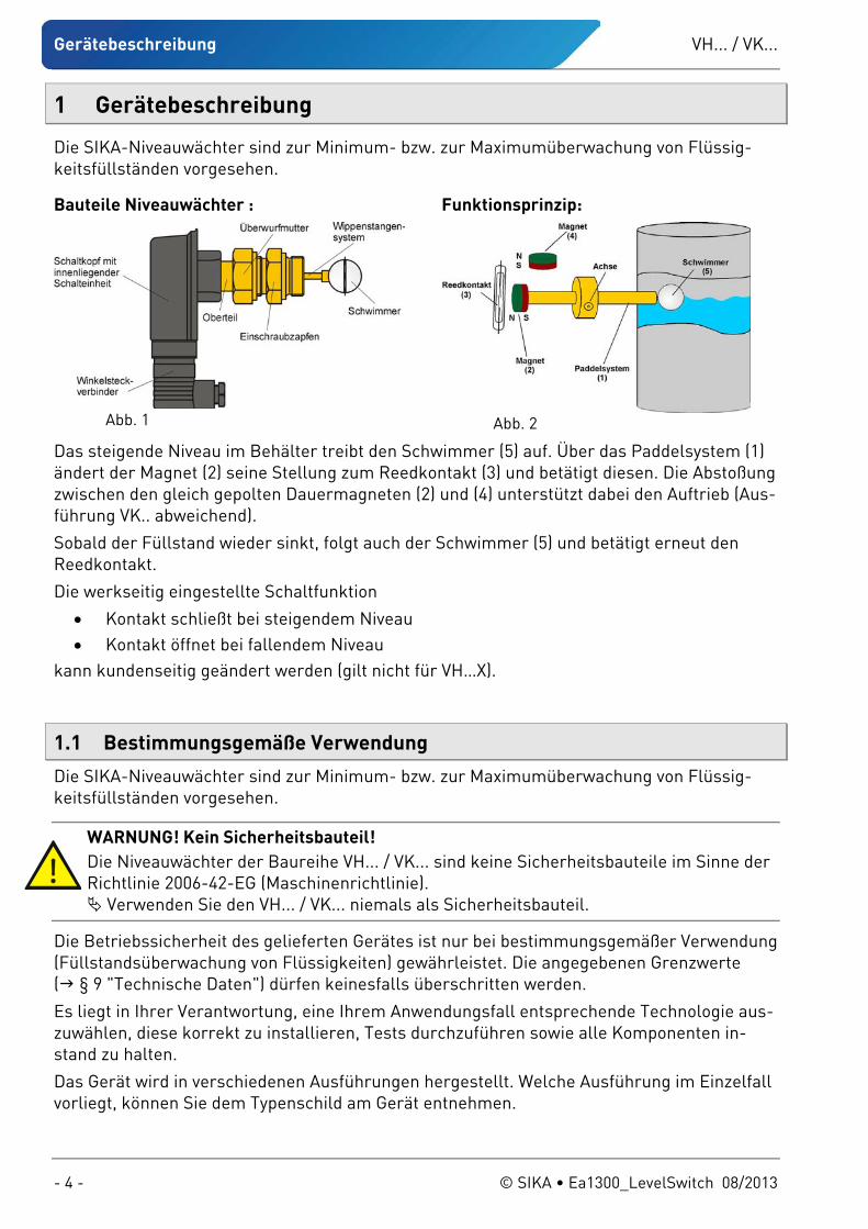
Die SIKA-Niveauwächter sind zur Minimum- bzw. zur Maximumüberwachung von Flüssig-keitsfüllständen vorgesehen.
Bauteile Niveauwächter :
Abb. 1
Funktionsprinzip:
Abb. 2
Das steigende Niveau im Behälter treibt den Schwimmer (5) auf. Über das Paddelsystem (1) ändert der Magnet (2) seine Stellung zum Reedkontakt (3) und betätigt diesen. Die Abstoßung zwischen den gleich gepolten Dauermagneten (2) und (4) unterstützt dabei den Auftrieb (Aus-führung VK.. abweichend).
Sobald der Füllstand wieder sinkt, folgt auch der Schwimmer (5) und betätigt erneut den Reedkontakt.
Die werkseitig eingestellte Schaltfunktion
• Kontakt schließt bei steigendem Niveau • Kontakt öffnet bei fallendem Niveau
kann kundenseitig geändert werden (gilt nicht für VH…X).
1.1 Bestimmungsgemäße Verwendung
Die SIKA-Niveauwächter sind zur Minimum- bzw. zur Maximumüberwachung von Flüssig-keitsfüllständen vorgesehen.
WARNUNG! Kein Sicherheitsbauteil! Die Niveauwächter der Baureihe VH... / VK... sind keine Sicherheitsbauteile im Sinne der Richtlinie 2006-42-EG (Maschinenrichtlinie).
Verwenden Sie den VH... / VK... niemals als Sicherheitsbauteil.
Die Betriebssicherheit des gelieferten Gerätes ist nur bei bestimmungsgemäßer Verwendung (Füllstandsüberwachung von Flüssigkeiten) gewährleistet. Die angegebenen Grenzwerte ( § 9 "Technische Daten") dürfen keinesfalls überschritten werden.
Es liegt in Ihrer Verantwortung, eine Ihrem Anwendungsfall entsprechende Technologie aus-zuwählen, diese korrekt zu installieren, Tests durchzuführen sowie alle Komponenten in-stand zu halten.
Das Gerät wird in verschiedenen Ausführungen hergestellt. Welche Ausführung im Einzelfall vorliegt, können Sie dem Typenschild am Gerät entnehmen.
VH... / VK... Gerätebeschreibung
Technische Änderungen vorbehalten - 5 -
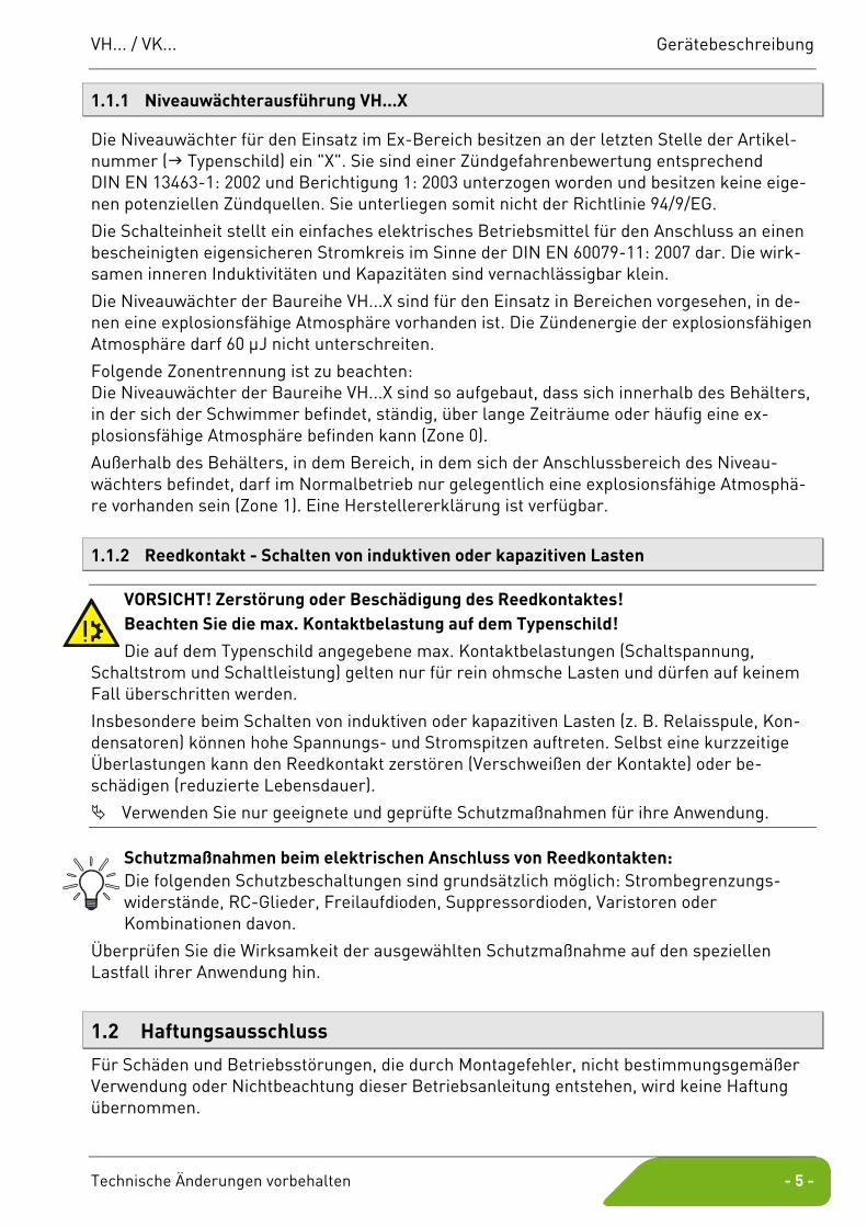
1.1.1 Niveauwächterausführung VH...X
Die Niveauwächter für den Einsatz im Ex-Bereich besitzen an der letzten Stelle der Artikel-nummer ( Typenschild) ein "X". Sie sind einer Zündgefahrenbewertung entsprechend DIN EN 13463-1: 2002 und Berichtigung 1: 2003 unterzogen worden und besitzen keine eige-nen potenziellen Zündquellen. Sie unterliegen somit nicht der Richtlinie 94/9/EG.
Die Schalteinheit stellt ein einfaches elektrisches Betriebsmittel für den Anschluss an einen bescheinigten eigensicheren Stromkreis im Sinne der DIN EN 60079-11: 2007 dar. Die wirk-samen inneren Induktivitäten und Kapazitäten sind vernachlässigbar klein.
Die Niveauwächter der Baureihe VH...X sind für den Einsatz in Bereichen vorgesehen, in de-nen eine explosionsfähige Atmosphäre vorhanden ist. Die Zündenergie der explosionsfähigen Atmosphäre darf 60 μJ nicht unterschreiten.
Folgende Zonentrennung ist zu beachten: Die Niveauwächter der Baureihe VH...X sind so aufgebaut, dass sich innerhalb des Behälters, in der sich der Schwimmer befindet, ständig, über lange Zeiträume oder häufig eine ex-plosionsfähige Atmosphäre befinden kann (Zone 0).
Außerhalb des Behälters, in dem Bereich, in dem sich der Anschlussbereich des Niveau-wächters befindet, darf im Normalbetrieb nur gelegentlich eine explosionsfähige Atmosphä-re vorhanden sein (Zone 1). Eine Herstellererklärung ist verfügbar.
1.1.2 Reedkontakt - Schalten von induktiven oder kapazitiven Lasten
VORSICHT! Zerstörung oder Beschädigung des Reedkontaktes! Beachten Sie die max. Kontaktbelastung auf dem Typenschild!
Die auf dem Typenschild angegebene max. Kontaktbelastungen (Schaltspannung, Schaltstrom und Schaltleistung) gelten nur für rein ohmsche Lasten und dürfen auf keinem Fall überschritten werden.
Insbesondere beim Schalten von induktiven oder kapazitiven Lasten (z. B. Relaisspule, Kon-densatoren) können hohe Spannungs- und Stromspitzen auftreten. Selbst eine kurzzeitige Überlastungen kann den Reedkontakt zerstören (Verschweißen der Kontakte) oder be-schädigen (reduzierte Lebensdauer).
Verwenden Sie nur geeignete und geprüfte Schutzmaßnahmen für ihre Anwendung.
Schutzmaßnahmen beim elektrischen Anschluss von Reedkontakten: Die folgenden Schutzbeschaltungen sind grundsätzlich möglich: Strombegrenzungs-widerstände, RC-Glieder, Freilaufdioden, Suppressordioden, Varistoren oder Kombinationen davon.
Überprüfen Sie die Wirksamkeit der ausgewählten Schutzmaßnahme auf den speziellen Lastfall ihrer Anwendung hin.
1.2 Haftungsausschluss
Für Schäden und Betriebsstörungen, die durch Montagefehler, nicht bestimmungsgemäßer Verwendung oder Nichtbeachtung dieser Betriebsanleitung entstehen, wird keine Haftung übernommen.
Sicherheitshinweise VH... / VK...
- 6 - © SIKA • Ea1300_LevelSwitch 08/2013
2 Sicherheitshinweise
Bevor Sie den VH... / VK... installieren, lesen Sie diese Betriebsanleitung sorgfältig durch. Werden die darin enthaltenen Anweisungen, insbesondere die Sicherheitshin-weise nicht beachtet, können Gefahren für Mensch, Geräte und Anlagen die Folge sein.
Die Niveauwächter entsprechen dem aktuellen Stand der Technik. Dies betrifft die Schalt-punktgenauigkeit, die Funktionsweise und den sicheren Betrieb der Geräte.
Um die sichere Bedienung zu gewährleisten, ist sachkundiges und sicherheitsbewusstes Verhalten der Bediener erforderlich.
SIKA gewährt persönlich oder durch entsprechende Literatur Hilfestellung für die An-wendung der Produkte. Der Kunde prüft die Einsetzbarkeit des Produktes auf der Basis unserer technischen Informationen. Mit dieser Prüfung gehen Gefahr und Risiko auf den Kunden über; unsere Gewährleitung erlischt.
2.1 Qualifiziertes Personal
Das Personal, das mit dem Einbau, der Bedienung und der Instandhaltung des Niveau-wächters beauftragt wird, muss die entsprechende Qualifikation aufweisen. Dies kann durch Schulung oder entsprechende Unterweisung geschehen. Dem Personal muss der Inhalt der vorliegenden Betriebsanleitung bekannt und jederzeit zugänglich sein.
Der elektrische Anschluss darf nur von einer Elektrofachkraft vorgenommen werden.
2.2 Spezielle Sicherheitshinweise
Bei allen Arbeiten sind die bestehenden nationalen Vorschriften zur Unfallverhütung und Sicherheit am Arbeitsplatz sowie ggf. interne Vorschriften des Betreibers einzuhalten, auch wenn diese nicht in dieser Anleitung genannt werden.
Um Schäden am Niveauwächter und an der zu überwachenden Anlage zu vermeiden, be-achten Sie, dass die SIKA-Niveauwächter ausschließlich zur Füllstandsüberwachung von Flüssigkeiten vorgesehen sind.
Folgen Sie unbedingt den Hinweisen zum Einbau des Niveauwächters. Vor dem Einbau des Niveauwächters muss sichergestellt sein, dass alle verwendeten Ma-
terialien des Niveauwächters gegen die zu überwachenden Medien und gegen alle äuße-ren Einflüsse ausreichend chemisch und mechanisch beständig sind.
Stellen Sie sicher, dass das Medium frei von magnetischen Partikeln ist und dass der Mindestwert für die Dichte ( § 9 "Technische Daten") gegeben ist.
Das Einfrieren des Mediums ist durch geeignete Maßnahmen zu verhindern. Soll der Niveauwächter später Umgebungstemperaturen <4 °C ausgesetzt werden, darf zuvor kein Betrieb, z. B. Testbetrieb, mit reinem Wasser erfolgen. Durch im Niveau-wächter verbliebenes Wasser könnten Frostschäden verursacht werden.
Auf Grund der Werkstoffbeständigkeit dürfen bei der Montage der Geräte VK... keine Fet-te, Öle usw. eingesetzt werden.
Achten Sie darauf, dass der max. angegebene Betriebsdruck nicht überschritten wird. Entfernen Sie niemals einen Niveauwächter oder seinen Körper aus einer unter Druck
stehenden Anlage.
VH... / VK... Materialspezifikationen der benetzten Bauteile
Technische Änderungen vorbehalten - 7 -
Wenn das zu überwachende Medium sehr hohe Temperaturen besitzt, wird auch der Ni-veauwächter extrem heiß. Vermeiden Sie Berührungen und stellen Sie keine temperatur-empfindlichen Gegenstände in der Nähe ab.
Schützen Sie den Niveauwächter vor magnetischen Fremdfeldern in der unmittelbaren Umgebung, da diese die Funktionsweise des Gerätes beeinträchtigen können.
Bei Geräten in Sonderausführung (kundenspezifischer Ausführung) können technische Daten gegenüber den Angaben dieser Anleitung abweichen. Bitte beachten Sie die An-gaben auf dem Typenschild.
WARNUNG! Lebensgefahr durch elektrische Spannung! Schalten Sie die elektrische Anlage immer spannungsfrei, bevor Sie der Anschlussleitung anschließen.
Typenschilder oder sonstige Hinweise auf dem Gerät dürfen weder entfernt noch un-kenntlich gemacht werden, da sonst jegliche Garantie und Herstellerverantwortung er-lischt.
2.3 Zusätzlich gilt für Niveauwächter VH...X
Es dürfen nur Medien mit einer minimalen Zündtemperatur >135 °C und einer Zünd-energie >60μJ mit dem Niveauwächter in Berührung kommen.
Beim Einbau und vor der Inbetriebnahme ist sicherzustellen, dass die mechanischen Pro-zessanschlüsse technisch dicht sind.
Bei der Zoneneinteilung ist die Dichtheit der Verschraubungselemente zu berück-sichtigen. Entsprechend den Einsatzbedingungen kann es daher erforderlich sein, die Verschraubungselemente regelmäßig auf ihre Dichtheit hin zu überprüfen.
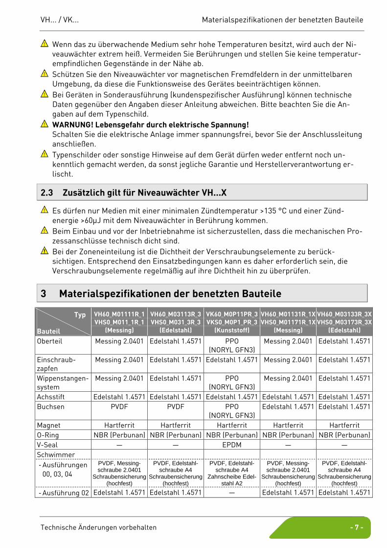
3 Materialspezifikationen der benetzten Bauteile
Typ
Bauteil
VH60_M01111R_1 VHS0_M011_1R_1
(Messing)
VH60_M03113R_3 VHS0_M031_3R_3
(Edelstahl)
VK60_M0P11PR_3 VKS0_M0P1_PR_3
(Kunststoff)
VH60_M01131R_1X VHS0_M01171R_1X
(Messing)
VH60_M03133R_3X VHS0_M03173R_3X
(Edelstahl)
Oberteil Messing 2.0401 Edelstahl 1.4571 PPO (NORYL GFN3)
Messing 2.0401 Edelstahl 1.4571
Einschraub-zapfen
Messing 2.0401 Edelstahl 1.4571 Edelstahl 1.4571 Messing 2.0401 Edelstahl 1.4571
Wippenstangen-system
Messing 2.0401 Edelstahl 1.4571 PPO (NORYL GFN3)
Messing 2.0401 Edelstahl 1.4571
Achsstift Edelstahl 1.4571 Edelstahl 1.4571 Edelstahl 1.4571 Edelstahl 1.4571 Edelstahl 1.4571 Buchsen PVDF PVDF PPO
(NORYL GFN3) Edelstahl 1.4571 Edelstahl 1.4571
Magnet Hartferrit Hartferrit Hartferrit Hartferrit Hartferrit O-Ring NBR (Perbunan) NBR (Perbunan) NBR (Perbunan) NBR (Perbunan) NBR (Perbunan) V-Seal — — EPDM — — Schwimmer - Ausführungen
00, 03, 04
PVDF, Messing-schraube 2.0401
Schraubensicherung (hochfest)
PVDF, Edelstahl-schraube A4
Schraubensicherung (hochfest)
PVDF, Edelstahl-schraube A4
Zahnscheibe Edel-stahl A2
PVDF, Messing-schraube 2.0401
Schraubensicherung (hochfest)
PVDF, Edelstahl-schraube A4
Schraubensicherung (hochfest)
- Ausführung 02 Edelstahl 1.4571 Edelstahl 1.4571 — Edelstahl 1.4571 Edelstahl 1.4571
Einbau des Niveauwächters VH... / VK...
- 8 - © SIKA • Ea1300_LevelSwitch 08/2013
4 Einbau des Niveauwächters
4.1 Allgemeine Einbauhinweise
Achten Sie bei der Wahl des Einbauortes darauf, dass die angegebenen Grenzwerte ( § 9 "Technische Daten") auf keinen Fall überschritten werden.
Verhindern Sie das Einfrieren des Mediums durch geeignete Maßnahmen. Soll der Niveauwächter später Umgebungstemperaturen <4°C ausgesetzt werden, darf zuvor kein Betrieb, z. B. Testbetrieb, mit reinem Wasser erfolgen. Durch im Niveau-wächter verbliebenes Wasser könnten Frostschäden verursacht werden.
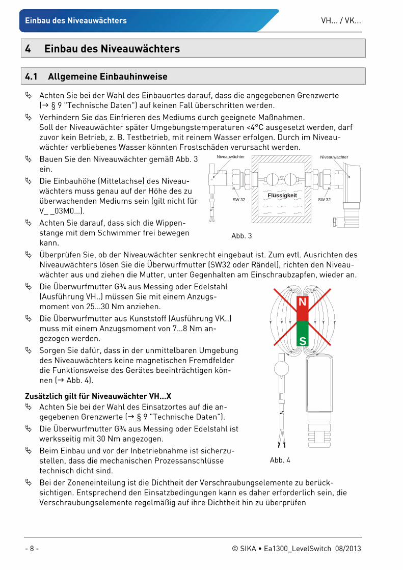
Bauen Sie den Niveauwächter gemäß Abb. 3 ein.
Die Einbauhöhe (Mittelachse) des Niveau-wächters muss genau auf der Höhe des zu überwachenden Mediums sein (gilt nicht für V_ _03M0…).
Achten Sie darauf, dass sich die Wippen-stange mit dem Schwimmer frei bewegen kann.
Überprüfen Sie, ob der Niveauwächter senkrecht eingebaut ist. Zum evtl. Ausrichten des Niveauwächters lösen Sie die Überwurfmutter (SW32 oder Rändel), richten den Niveau-wächter aus und ziehen die Mutter, unter Gegenhalten am Einschraubzapfen, wieder an.
Die Überwurfmutter G¾ aus Messing oder Edelstahl (Ausführung VH..) müssen Sie mit einem Anzugs-moment von 25…30 Nm anziehen.
Die Überwurfmutter aus Kunststoff (Ausführung VK..) muss mit einem Anzugsmoment von 7…8 Nm an-gezogen werden.
Sorgen Sie dafür, dass in der unmittelbaren Umgebung des Niveauwächters keine magnetischen Fremdfelder die Funktionsweise des Gerätes beeinträchtigen kön-nen ( Abb. 4).
Zusätzlich gilt für Niveauwächter VH...X Achten Sie bei der Wahl des Einsatzortes auf die an-
gegebenen Grenzwerte ( § 9 "Technische Daten"). Die Überwurfmutter G¾ aus Messing oder Edelstahl ist
werksseitig mit 30 Nm angezogen. Beim Einbau und vor der Inbetriebnahme ist sicherzu-
stellen, dass die mechanischen Prozessanschlüsse technisch dicht sind.
Bei der Zoneneinteilung ist die Dichtheit der Verschraubungselemente zu berück-sichtigen. Entsprechend den Einsatzbedingungen kann es daher erforderlich sein, die Verschraubungselemente regelmäßig auf ihre Dichtheit hin zu überprüfen
SW 32SW 32
Niveauwächter
Flüssigkeit
Niveauwächter
Abb. 3
N
S
Abb. 4
VH... / VK... Elektrischer Anschluss
Technische Änderungen vorbehalten - 9 -
5 Elektrischer Anschluss
5.1 Allgemeine Hinweise zum elektrischen Anschluss
GEFAHR! Lebensgefahr durch elektrischen Strom! Der elektrische Anschluss des VH... / VK... darf nur von einer Elektrofachkraft vor-genommen werden.
Schalten Sie die elektrische Anlage spannungsfrei, bevor Sie den VH... / VK... anschließen.
VORSICHT! Zerstörung oder Beschädigung des Reedkontaktes! Die auf dem Typenschild angegebene max. Kontaktbelastungen gelten nur für rein ohm-sche Lasten und dürfen auf keinem Fall überschritten werden.
Beachten Sie § 1.1.2: Reedkontakt - Schalten von induktiven oder kapazitiven Lasten.
Zusätzlich gilt für die Niveauwächterausführung VH...X Die Niveauwächterausführung VH...X können Sie als einfaches elektrisches Betriebs-
mittel an einen bescheinigten eigensicheren Stromkreis anschließen. Die Niveauwächterausführung VH...X ist entweder mit Winkelsteckverbinder EN 175301-
803-A oder mit fester Anschlussleitung ausgerüstet. Zur Vermeidung von elektrostatischer Aufladung müssen Sie die Geräte über den Winkel-
steckverbinder bzw. über die feste Anschlussleitung an den Potenzialausgleich anschließen.
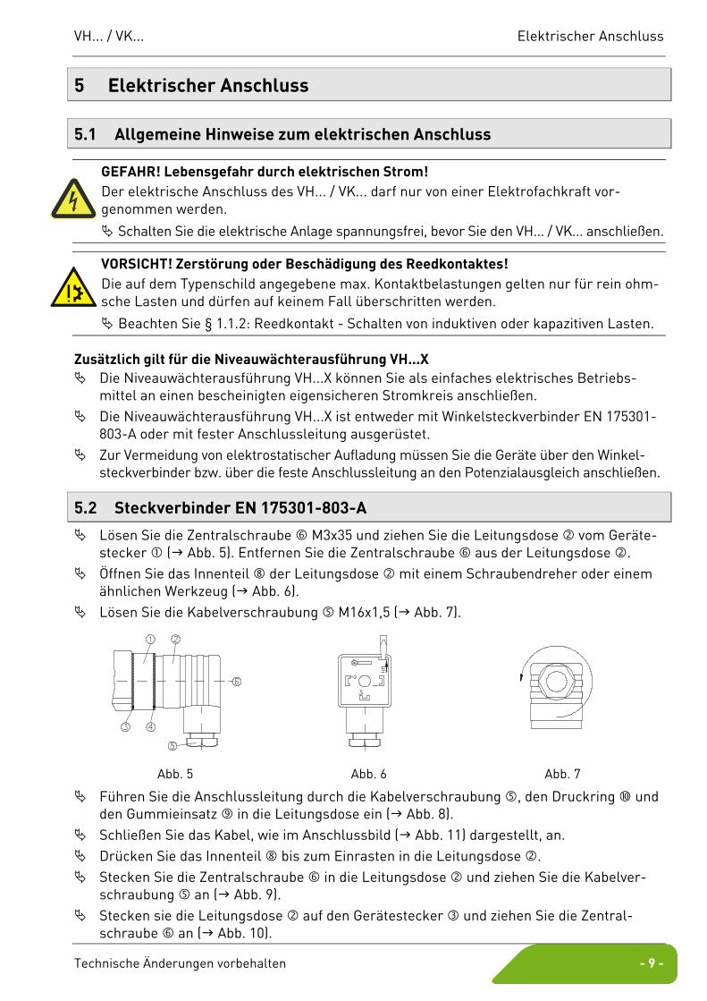
5.2 Steckverbinder EN 175301-803-A
Lösen Sie die Zentralschraube M3x35 und ziehen Sie die Leitungsdose vom Geräte-stecker ( Abb. 5). Entfernen Sie die Zentralschraube aus der Leitungsdose .
Öffnen Sie das Innenteil der Leitungsdose mit einem Schraubendreher oder einem ähnlichen Werkzeug ( Abb. 6).
Lösen Sie die Kabelverschraubung M16x1,5 ( Abb. 7).
Abb. 5 Abb. 6 Abb. 7
Führen Sie die Anschlussleitung durch die Kabelverschraubung , den Druckring und den Gummieinsatz in die Leitungsdose ein ( Abb. 8).
Schließen Sie das Kabel, wie im Anschlussbild ( Abb. 11) dargestellt, an. Drücken Sie das Innenteil bis zum Einrasten in die Leitungsdose . Stecken Sie die Zentralschraube in die Leitungsdose und ziehen Sie die Kabelver-
schraubung an ( Abb. 9). Stecken sie die Leitungsdose auf den Gerätestecker und ziehen Sie die Zentral-
schraube an ( Abb. 10).

Elektrischer Anschluss VH... / VK...
- 10 - © SIKA • Ea1300_LevelSwitch 08/2013
Abb. 8 Abb. 9 Abb. 10
Zur Gewährleistung der Schutzart IP 65 nach EN 60529 muss die verwendete Anschluss-leitung einen Manteldurchmesser von 4,5 bis 10 mm aufweisen.
Ferner müssen Sie darauf achten, dass alle Dichtungen , und des Steckverbinders ordnungsgemäß eingelegt sind.
Niveauwächterausführung VHS0.../VKS0... Niveauwächterausführung VHS0...X Reedkontakt
Reedkontakt
nicht belegt
nicht belegt
1
2
3ReedkontaktReedkontakt
nicht belegt
13
2
Reedkontakt
Reedkontakt
nicht belegt
Potentialausgleich*
1
2
3
Abb. 11 *) Zur Vermeidung von elektrostatischer Aufladung müssen Sie die Geräte der Ausführung VH...X
über den Winkelsteckverbinder an den Potenzialausgleich anschließen.
5.3 Sensorstecker M12x1 (4-polig)
Zum Anschluss verwenden Sie nur geeignete Kupplungsdosen M12x1. Diese sind mit di-rekt angespritzter Leitung oder zum Selbstkonfektionieren als Zubehör lieferbar.
5.4 Feste Anschlussleitung
Schließen Sie die Anschlussleitung nach dem Anschlussbild ( Abb. 13) an: Niveauwächterausführung
Pinbelegung des Anschlusssteckers:
Reedkontakt
Reedkontakt
nicht belegtnicht belegt
1
4
23
ReedkontaktReedkontakt
nicht belegtnicht belegt2
4 31
Abb. 12
VH60.../VK60... VH60...X braun
blau
Reedkontakt
Reedkontakt
Potential-ausgleich*
braun
blau
Reedkontakt
Reedkontakt
grün/gelb
Abb. 13 * Zur Vermeidung von elektrostatischer Aufladung müssen Sie die Geräte der Ausführung VH3...X
über die feste Anschlussleitung an den Potenzialausgleich anschließen.
VH... / VK... Verstellen der Schalteinheit
Technische Änderungen vorbehalten - 11 -
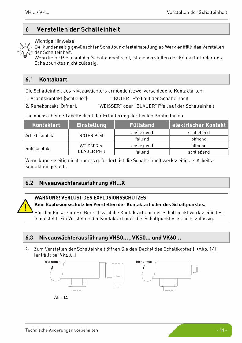
6 Verstellen der Schalteinheit
Wichtige Hinweise! Bei kundenseitig gewünschter Schaltpunktfesteinstellung ab Werk entfällt das Verstellen der Schalteinheit. Wenn keine Pfeile auf der Schalteinheit sind, ist ein Verstellen der Kontaktart oder des Schaltpunktes nicht zulässig.
6.1 Kontaktart
Die Schalteinheit des Niveauwächters ermöglicht zwei verschiedene Kontaktarten:
1. Arbeitskontakt (Schließer): "ROTER" Pfeil auf der Schalteinheit
2. Ruhekontakt (Öffner): "WEISSER" oder "BLAUER" Pfeil auf der Schalteinheit
Die nachstehende Tabelle dient der Erläuterung der beiden Kontaktarten:
Kontaktart Einstellung Füllstand elektrischer Kontakt ansteigend schließend
Arbeitskontakt ROTER Pfeil fallend öffnend
ansteigend öffnend Ruhekontakt
WEISSER o. BLAUER Pfeil fallend schließend
Wenn kundenseitig nicht anders gefordert, ist die Schalteinheit werksseitig als Arbeits-kontakt eingestellt.
6.2 Niveauwächterausführung VH...X
WARNUNG! VERLUST DES EXPLOSIONSSCHUTZES! Kein Explosionsschutz bei Verstellen der Kontaktart oder des Schaltpunktes.
Für den Einsatz im Ex-Bereich wird die Kontaktart und der Schaltpunkt werksseitig fest eingestellt. Ein Verstellen der Kontaktart oder des Schaltpunktes ist nicht zulässig.
6.3 Niveauwächterausführung VHS0... , VKS0... und VK60...
Zum Verstellen der Schalteinheit öffnen Sie den Deckel des Schaltkopfes ( Abb. 14) (entfällt bei VK60...)
hier öffnen
hier öffnen
Abb.14
Verstellen der Schalteinheit VH... / VK...
- 12 - © SIKA • Ea1300_LevelSwitch 08/2013
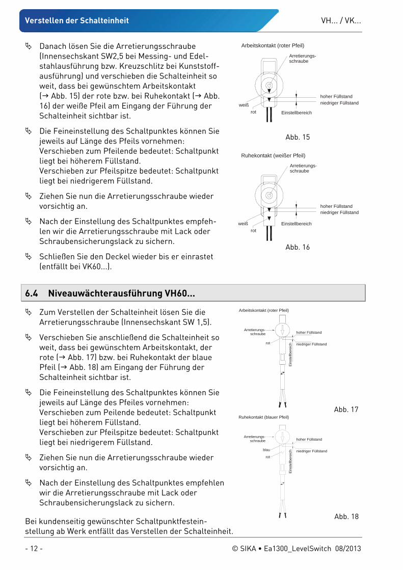
Danach lösen Sie die Arretierungsschraube (Innensechskant SW2,5 bei Messing- und Edel-stahlausführung bzw. Kreuzschlitz bei Kunststoff-ausführung) und verschieben die Schalteinheit so weit, dass bei gewünschtem Arbeitskontakt ( Abb. 15) der rote bzw. bei Ruhekontakt ( Abb. 16) der weiße Pfeil am Eingang der Führung der Schalteinheit sichtbar ist.
Die Feineinstellung des Schaltpunktes können Sie jeweils auf Länge des Pfeils vornehmen: Verschieben zum Pfeilende bedeutet: Schaltpunkt liegt bei höherem Füllstand. Verschieben zur Pfeilspitze bedeutet: Schaltpunkt liegt bei niedrigerem Füllstand.
Ziehen Sie nun die Arretierungsschraube wieder vorsichtig an.
Nach der Einstellung des Schaltpunktes empfeh-len wir die Arretierungsschraube mit Lack oder Schraubensicherungslack zu sichern.
Schließen Sie den Deckel wieder bis er einrastet (entfällt bei VK60...).
6.4 Niveauwächterausführung VH60...
Zum Verstellen der Schalteinheit lösen Sie die Arretierungsschraube (Innensechskant SW 1,5).
Verschieben Sie anschließend die Schalteinheit so weit, dass bei gewünschtem Arbeitskontakt, der rote ( Abb. 17) bzw. bei Ruhekontakt der blaue Pfeil ( Abb. 18) am Eingang der Führung der Schalteinheit sichtbar ist.
Die Feineinstellung des Schaltpunktes können Sie jeweils auf Länge des Pfeiles vornehmen: Verschieben zum Peilende bedeutet: Schaltpunkt liegt bei höherem Füllstand. Verschieben zur Pfeilspitze bedeutet: Schaltpunkt liegt bei niedrigerem Füllstand.
Ziehen Sie nun die Arretierungsschraube wieder vorsichtig an.
Nach der Einstellung des Schaltpunktes empfehlen wir die Arretierungsschraube mit Lack oder Schraubensicherungslack zu sichern.
Bei kundenseitig gewünschter Schaltpunktfestein-stellung ab Werk entfällt das Verstellen der Schalteinheit.
hoher Füllstandniedriger Füllstand
Einstellbereich
Arretierungs-schraube
rotweiß
Arbeitskontakt (roter Pfeil)
Abb. 15
hoher Füllstandniedriger Füllstand
Einstellbereich
Arretierungs-schraube
rotweiß
Ruhekontakt (weißer Pfeil)
Abb. 16
hoher Füllstand
niedriger Füllstand
Eins
tellb
erei
ch
Arretierungs-schraube
rot
Arbeitskontakt (roter Pfeil)
Abb. 17
blau
hoher Füllstand
niedriger Füllstand
Eins
tellb
erei
ch
Arretierungs-schraube
rot
Ruhekontakt (blauer Pfeil)
Abb. 18
VH... / VK... Wartung und Reinigung
Technische Änderungen vorbehalten - 13 -
7 Wartung und Reinigung
Wartung: Der Niveauwächter VH... / VK... ist wartungsfrei und kann auch nicht vom Anwender repariert werden. Bei einem Defekt muss das Gerät ausgetauscht oder zur Reparatur an den Herstel-ler zurückgeschickt werden.
VORSICHT! Materialschaden! Beim Öffnen des Gerätes können wichtige Bauteile oder Komponenten beschädigt werden.
Öffnen Sie niemals das Gerät.
Reinigung: Reinigen Sie den VH... / VK... mit einem trockenen oder leicht angefeuchteten, fusselfreien Tuch. Verwenden Sie keine scharfen Gegenstände oder aggressive Reinigungsmittel beim Reinigen.
8 Demontage und Entsorgung
VORSICHT! Verletzungsgefahr! Entfernen Sie niemals einen Niveauwächter oder seinen Körper aus einer unter Druck stehenden Anlage.
Sorgen Sie dafür, dass die Anlage fachgerecht ausgeschaltet wird.
Vor der Demontage: Überprüfen Sie vor der Demontage, ob
die Anlage ausgeschaltet ist und sich in einem sicheren und stromlosen Zustand befindet. die Anlage drucklos und abgekühlt ist.
Demontage: Entfernen Sie die elektrischen Anschlüsse. Bauen Sie den VH... / VK... mit passenden Werkzeugen aus.
Entsorgung:
KEIN HAUSMÜLL! Der VH... / VK... besteht aus unterschiedlichen Werkstoffen ( § 3). Er darf nicht zu-sammen mit Hausmüll entsorgt werden.
Führen Sie den VH... / VK... der lokalen Wieder-verwertung zu oder
schicken Sie den VH... / VK... an Ihren Lieferanten bzw. SIKA zurück.
+p
Technische Daten VH... / VK...
- 14 - © SIKA • Ea1300_LevelSwitch 08/2013
9 Technische Daten
Bei kundenspezifischen Ausführung können technische Daten gegenüber den Angaben die-ser Anleitung abweichen. Bitte beachten Sie die Angaben auf dem Typenschild.
Baureihe VH.../VK... VH6...X VHS...X Min. Mediumsdichte: - Edelstahl-Zylinderschwimmer - PVDF-Schwimmer
0,83 kg/dm3 0,78 kg/dm3
Min. Mediumstemperatur: Wasser +5 °C; andere Medien -10 °C (nicht gefrierend)
Max. Mediumstemperatur: - Metallausführung VH.. - Kunststoffausführung VK..
110 °C 100 °C
100 °C
—
Min. Umgebungstemperatur: -25 °C
Max. Umgebungstemperatur: - VHS0 ../VKS0 .. - VH60 .. - VK60 ..
80 °C 80 °C 70 °C
80 °C
Nenndruck: - Metallausführung VH.. - Kunststoffausführung VK..
PN 25 PN 10
PN 25
—
Einschaltpunkt, bezogen auf Mittel-achse (Wasser, 20 °C) (V_ _03M0… abweichend)
-4...0 mm
Schalthysterese (V_ _03M0… abweichend)
ca. 1...4 mm
Kontaktbelastbarkeit: - Schaltstrom - Schaltspannung - Schaltleistung
max. 1 A max. 230 VAC oder 48 VDC max. 26 VA oder 20 W
Schaltfunktion Kontakt öffnet bei fallendem Niveau (Änderung auf Ruhe-
kontakt möglich)
Kontakt öffnet bei fallendem Niveau
Schutzklasse (DIN EN 60730-1) II I II
Schutzart (DIN EN 60529) IP 65
Gilt für Niveauwächter VH...X Die Zündenergie der explosionsfähigen Atmosphäre darf 60 μJ nicht unterschreiten. Die wirksamen inneren Induktivitäten und Kapazitäten sind vernachlässigbar klein.
10 Zulassungen Die SIKA-Niveauwächter sind vom TÜV Rheinland bauartgeprüft, Prüfzeichen R 60077518 vom 04.12.2012 (gilt nicht für Ausführung mit Sensorstecker M12x1 und nicht für VH...X).
VH... / VK... EG-Konformitätserklärung
Technische Änderungen vorbehalten - 15 -
11 EG-Konformitätserklärung

VH... / VK...
- 16 - © SIKA • Ea1300_LevelSwitch 08/2013
Mechanische Messtechnik
Durchflussmesstechnik
Elektronische Mess- & Kalibriertechnik
SIKA Dr.Siebert & Kühn GmbH & Co. KG Struthweg 7–9 D-34260 Kaufungen Germany
℡ +49 (0)5605 803-0 +49 5605 803-54
[email protected] www.sika.net
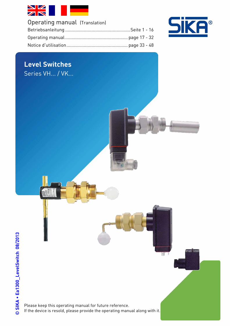
Please keep this operating manual for future reference. If the device is resold, please provide the operating manual along with it. ©
SIK
A •
Ea1
300_
Leve
lSw
itch
08/
2013
.
Level Switches Series VH... / VK...
Operating manual (Translation)
Betriebsanleitung ....................................................Seite 1 - 16
Operating manual .................................................. page 17 - 32
Notice d'utilisation................................................. page 33 - 48
VH... / VK...
- 18 - © SIKA • Ea1300_LevelSwitch 08/2013
Table of contents page
0 About this operating manual.......................................................................................19 1 Device description .......................................................................................................20 1.1 Intended use..............................................................................................................20 1.1.1 Level switch version VH...X...................................................................................21 1.1.2 Reed contact - Switching of inductive or capacitive loads...................................21 1.2 Exclusion of liability ..................................................................................................21
2 Safety instructions.......................................................................................................22 2.1 Qualified personnel ...................................................................................................22 2.2 Special safety instructions........................................................................................22 2.3 Additional information for the VH...X level switch ....................................................23
3 Material specifications of wetted components ...........................................................23 4 Level switch installation..............................................................................................24 4.1 General installation instructions ..............................................................................24
5 Electrical connection...................................................................................................25 5.1 General electrical connection information...............................................................25 5.2 Plug connector EN 175301-803-A.............................................................................25 5.3 Sensor plug M12x1 (4-pole) ......................................................................................26 5.4 Fixed connecting cable..............................................................................................26
6 Adjusting the switching unit........................................................................................27 6.1 Type of contact ..........................................................................................................27 6.2 Level switch version VH...X .......................................................................................27 6.3 Level switch versions VHS0... , VKS0... and VK60... ..................................................27 6.4 Level switch version VH60... .....................................................................................28
7 Maintenance and Cleaning..........................................................................................29 8 Decommissioning and Disposal..................................................................................29 9 Technical data .............................................................................................................30 10 Approvals.....................................................................................................................30 11 EC declaration of conformity.......................................................................................31
Copyright notice: The reproduction, distribution and utilization of this operating manual as well as the communication of its contents to others without express authorization is prohibited. Offenders will be held liable for the payment of damages. All rights reserved in the event of the grant of a patent, utility model or design.
VH... / VK... About this operating manual
Technical changes reserved - 19 -
0 About this operating manual
• The operating manual is aimed at specialists and semi-skilled personnel.
• Before each step, read through the relevant advice carefully and keep to the specified order.
• Thoroughly read and understand the information in the section "Safety instructions".
If you have any problems or questions, please contact your supplier or contact us directly at:
Dr. Siebert & Kühn GmbH & Co. KG Struthweg 7-9 • D - 34260 Kaufungen ℡ 05605-803 0 • 05605-803 54
[email protected] • www.sika.net
Hazard signs and other symbols used:
DANGER! Risk of death due to electric current! This sign indicates dangers which could lead to serious health defects or to death.
CAUTION! Risk of injury! This sign indicates dangers that cause personal injuries that can lead to health defects or cause considerable damage to property.
+p
CAUTION! Risk of injury in the case of excessive pressure! This sign indicates dangers which could arise from excessive pressure in a piece of equip-ment.
CAUTION! Material damage! This sign indicates actions which could lead to possible damage to material or environmental damage.
ADHERE TO OPERATING MANUAL!
NOTICE! This symbol indicates important notices, tips or information.
Pay attention to and comply with informa-tion that is marked with this symbol.
Follow the specified instructions and steps. Adhere to the given order.
Check the specified points or notices. Reference to another section, document or
source. • Item.
Device description VH... / VK...
- 20 - © SIKA • Ea1300_LevelSwitch 08/2013
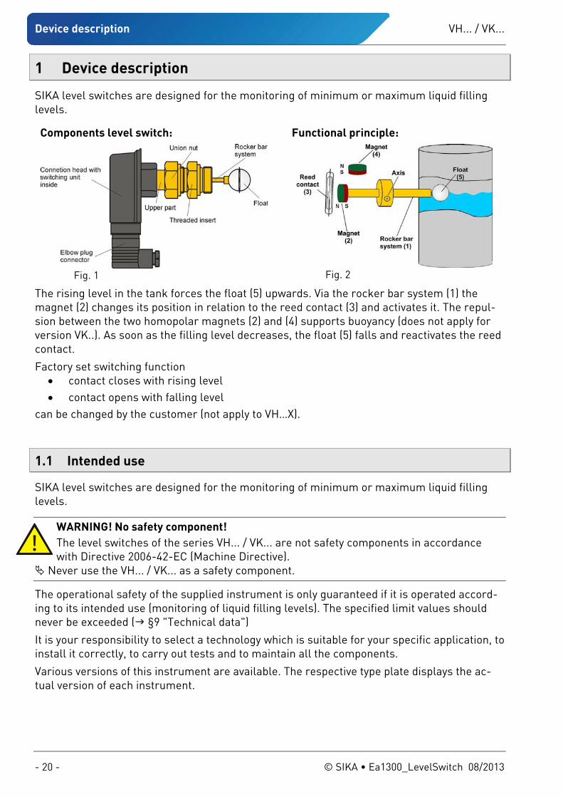
1 Device description
SIKA level switches are designed for the monitoring of minimum or maximum liquid filling levels.
Components level switch:
Fig. 1
Functional principle:
Fig. 2
The rising level in the tank forces the float (5) upwards. Via the rocker bar system (1) the magnet (2) changes its position in relation to the reed contact (3) and activates it. The repul-sion between the two homopolar magnets (2) and (4) supports buoyancy (does not apply for version VK..). As soon as the filling level decreases, the float (5) falls and reactivates the reed contact.
Factory set switching function • contact closes with rising level • contact opens with falling level
can be changed by the customer (not apply to VH…X).
1.1 Intended use
SIKA level switches are designed for the monitoring of minimum or maximum liquid filling levels.
WARNING! No safety component! The level switches of the series VH... / VK... are not safety components in accordance with Directive 2006-42-EC (Machine Directive).
Never use the VH... / VK... as a safety component.
The operational safety of the supplied instrument is only guaranteed if it is operated accord-ing to its intended use (monitoring of liquid filling levels). The specified limit values should never be exceeded ( §9 "Technical data")
It is your responsibility to select a technology which is suitable for your specific application, to install it correctly, to carry out tests and to maintain all the components.
Various versions of this instrument are available. The respective type plate displays the ac-tual version of each instrument.
VH... / VK... Device description
Technical changes reserved - 21 -
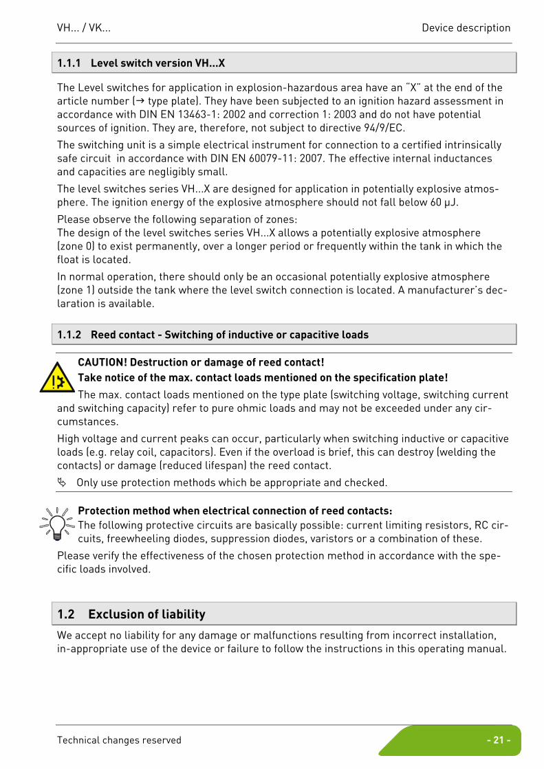
1.1.1 Level switch version VH...X
The Level switches for application in explosion-hazardous area have an “X” at the end of the article number ( type plate). They have been subjected to an ignition hazard assessment in accordance with DIN EN 13463-1: 2002 and correction 1: 2003 and do not have potential sources of ignition. They are, therefore, not subject to directive 94/9/EC.
The switching unit is a simple electrical instrument for connection to a certified intrinsically safe circuit in accordance with DIN EN 60079-11: 2007. The effective internal inductances and capacities are negligibly small.
The level switches series VH...X are designed for application in potentially explosive atmos-phere. The ignition energy of the explosive atmosphere should not fall below 60 μJ.
Please observe the following separation of zones: The design of the level switches series VH...X allows a potentially explosive atmosphere (zone 0) to exist permanently, over a longer period or frequently within the tank in which the float is located.
In normal operation, there should only be an occasional potentially explosive atmosphere (zone 1) outside the tank where the level switch connection is located. A manufacturer’s dec-laration is available.
1.1.2 Reed contact - Switching of inductive or capacitive loads
CAUTION! Destruction or damage of reed contact! Take notice of the max. contact loads mentioned on the specification plate!
The max. contact loads mentioned on the type plate (switching voltage, switching current and switching capacity) refer to pure ohmic loads and may not be exceeded under any cir-cumstances.
High voltage and current peaks can occur, particularly when switching inductive or capacitive loads (e.g. relay coil, capacitors). Even if the overload is brief, this can destroy (welding the contacts) or damage (reduced lifespan) the reed contact.
Only use protection methods which be appropriate and checked.
Protection method when electrical connection of reed contacts: The following protective circuits are basically possible: current limiting resistors, RC cir-cuits, freewheeling diodes, suppression diodes, varistors or a combination of these.
Please verify the effectiveness of the chosen protection method in accordance with the spe-cific loads involved.
1.2 Exclusion of liability
We accept no liability for any damage or malfunctions resulting from incorrect installation, in-appropriate use of the device or failure to follow the instructions in this operating manual.
Safety instructions VH... / VK...
- 22 - © SIKA • Ea1300_LevelSwitch 08/2013
2 Safety instructions
Before you install the VH... / VK..., read through this operating manual carefully. If the in-structions contained within it are not followed, in particular the safety guidelines, this could result in danger for people, the environment, and the device and the system it is
connected to.
The VH... / VK... correspond to the state-of-the-art technology. This concerns switching point accuracy, functioning and safe operation of the device.
In order to guarantee that the device operates safely, the operator must act competently and be conscious of safety issues.
SIKA provides support for the use of its products either personally or via relevant literature. The customer verifies that our product is fit for purpose based on our technical information. With this verification all hazards and risks are transferred to our customers; our warranty is not valid.
2.1 Qualified personnel
The personnel who are charged for the installation, operation and maintenance of the VH... / VK... must hold a relevant qualification. This can be based on training or relevant tuition. The personnel must be aware of this operating manual and have access to it at all times.
The electrical connection should only be carried out by a fully qualified electrician.
2.2 Special safety instructions
In all work, the existing national regulations for accident prevention and safety in the workplace must be complied with. Any internal regulations of the operator must also be complied with, even if these are not mentioned in this manual.
To avoid damages to the level switch and the monitored system, only use the SIKA level switch to monitor the filling level of liquids.
Always follow and adhere to the level switch installation instructions. Prior to level switch installation, ensure that the materials of the level switch are chemi-
cally and mechanically resistant to the media which is to be monitored and to all external factors.
Ensure that the medium is free from magnetic particles and that the minimum density value exists ( § 9 “Technical data”).
Suitable measures should be taken to prevent the medium from freezing. If the level switch is to be used in ambient temperatures of <4 °C, do not carry out any op-eration beforehand with pure water, e.g. a test run. Residual water in the level switch can result in frost damage.
Due to the material resistance, no lubricants, oils etc. should be used when installing the VK.. level switch.
Ensure that the maximum specified operating pressure is not exceeded. Never remove a level switch or the upper parts of a level switch from a pressurised sys-
tem.
VH... / VK... Material specifications of wetted components
Technical changes reserved - 23 -
If the medium which is to be monitored is very hot, the level switch will also become ex-tremely hot. In this case, neither touch the level switch nor place any heat-sensitive ob-jects in its vicinity.
Protect the level switch against external magnetic fields in the immediate vicinity, since these can impair instrument functioning.
The technical data of special versions (customised versions) may differ from the data in these instructions. Please observe the information specified on the type plate.
WARNING! Danger high voltages! De-energise the system before connecting the wires of the connecting cable.
It is prohibited to remove or make type plates or any other information attached to the equipment indecipherable, otherwise all warranties and the responsibility of the manu-facturer no longer apply.
2.3 Additional information for the VH...X level switch
The level switch should only be used for media with a minimum ignition temperature of >135 °C and ignition energy of >60 μJ.
When installing and before starting-up, it is to be guaranteed that the mechanical process connections are technically tight.
Always consider the sealing of the screwing elements for the zone allocation. Depending on the operating conditions, it may be necessary to regularly check the sealing of the screwing elements.
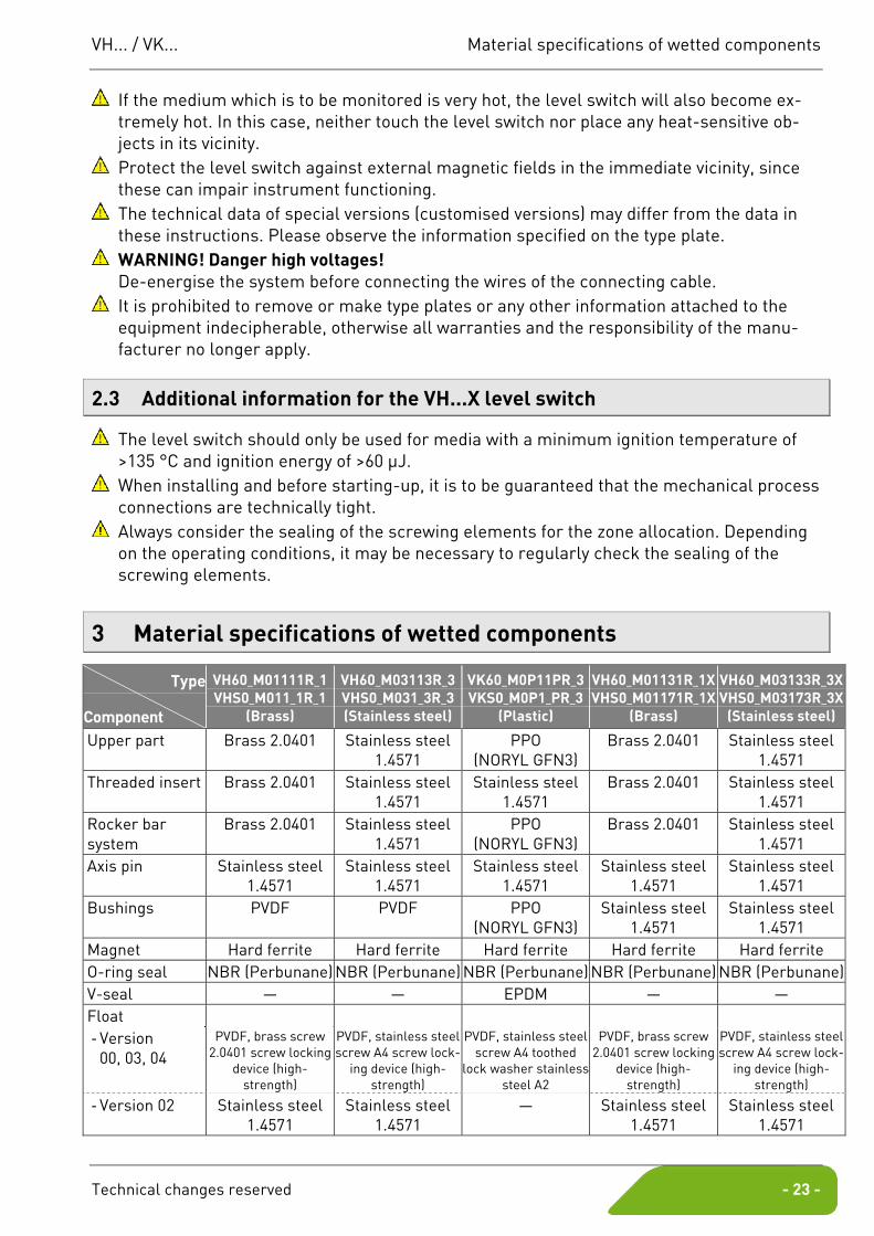
3 Material specifications of wetted components
Type
Component
VH60_M01111R_1 VHS0_M011_1R_1
(Brass)
VH60_M03113R_3 VHS0_M031_3R_3 (Stainless steel)
VK60_M0P11PR_3 VKS0_M0P1_PR_3
(Plastic)
VH60_M01131R_1X VHS0_M01171R_1X
(Brass)
VH60_M03133R_3X VHS0_M03173R_3X
(Stainless steel)
Upper part Brass 2.0401 Stainless steel 1.4571
PPO (NORYL GFN3)
Brass 2.0401 Stainless steel 1.4571
Threaded insert Brass 2.0401 Stainless steel 1.4571
Stainless steel 1.4571
Brass 2.0401 Stainless steel 1.4571
Rocker bar system
Brass 2.0401 Stainless steel 1.4571
PPO (NORYL GFN3)
Brass 2.0401 Stainless steel 1.4571
Axis pin Stainless steel 1.4571
Stainless steel 1.4571
Stainless steel 1.4571
Stainless steel 1.4571
Stainless steel 1.4571
Bushings PVDF PVDF PPO (NORYL GFN3)
Stainless steel 1.4571
Stainless steel 1.4571
Magnet Hard ferrite Hard ferrite Hard ferrite Hard ferrite Hard ferrite O-ring seal NBR (Perbunane) NBR (Perbunane) NBR (Perbunane) NBR (Perbunane) NBR (Perbunane) V-seal — — EPDM — — Float - Version
00, 03, 04 PVDF, brass screw
2.0401 screw locking device (high-
strength)
PVDF, stainless steel screw A4 screw lock-
ing device (high-strength)
PVDF, stainless steel screw A4 toothed
lock washer stainless steel A2
PVDF, brass screw 2.0401 screw locking
device (high-strength)
PVDF, stainless steel screw A4 screw lock-
ing device (high-strength)
- Version 02 Stainless steel 1.4571
Stainless steel 1.4571
— Stainless steel 1.4571
Stainless steel 1.4571
Level switch installation VH... / VK...
- 24 - © SIKA • Ea1300_LevelSwitch 08/2013
4 Level switch installation
4.1 General installation instructions
When choosing the installation site, ensure that the specified limit values are not ex-ceeded ( § 9 “Technical data”).
Suitable measures should be taken to prevent the medium from freezing. If the level switch is to be used in ambient temperatures of <4 °C, do not carry out any operation beforehand with pure water, e.g. a test run. Residual water in the level switch can result in frost damage.
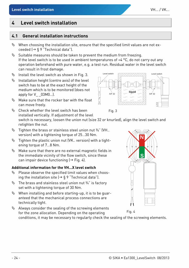
Install the level switch as shown in Fig. 3. Installation height (centre axis) of the level
switch has to be at the exact height of the medium which is to be monitored (does not apply for V_ _03M0…).
Make sure that the rocker bar with the float can move freely.
Check whether the level switch has been installed vertically. If adjustment of the level switch is necessary, loosen the union nut (size 32 or knurled), align the level switch and retighten the nut.
Tighten the brass or stainless steel union nut ¾” (VH.. version) with a tightening torque of 25…30 Nm.
Tighten the plastic union nut (VK.. version) with a tight-ening torque of 7…8 Nm.
Make sure that there are no external magnetic fields in the immediate vicinity of the flow switch, since these can impair device functioning ( Fig. 4).
Additional information for the VH...X level switch Please observe the specified limit values when choos-
ing the installation site ( § 9 “Technical data”). The brass and stainless steel union nut ¾” is factory
set with a tightening torque of 30 Nm. When installing and before starting-up, it is to be guar-
anteed that the mechanical process connections are technically tight.
Always consider the sealing of the screwing elements for the zone allocation. Depending on the operating conditions, it may be necessary to regularly check the sealing of the screwing elements.
A/F 32A/F 32liquid
Level switch Level switch
Fig. 3
N
S
Fig. 4
VH... / VK... Electrical connection
Technical changes reserved - 25 -
5 Electrical connection
5.1 General electrical connection information
DANGER! Risk of death due to electric current! The electrical connection should only be carried out by a fully qualified electrician.
Always de-energise the VH... / VK... before connecting the wires of the connecting cable.
CAUTION! Destruction or damage of reed contact! The max. contact loads mentioned on the type plate refer to pure ohmic loads and may not be exceeded under any circumstances.
Pay attention to § 1.1.2 Reed contact - Switching of inductive or capacitive loads.
Additional information for the VH...X level switch The VH...X level switch can be connected as a simple electrical instrument in a certified
intrinsically safe circuit. The VH...X level switch is equipped with either a elbow plug connector EN 175301-803-A
or a fixed connecting cable. To prevent electrostatic charging the devices have to be connected to the equipotential
bonding via the elbow plug connector or the fixed connecting cable.
5.2 Plug connector EN 175301-803-A
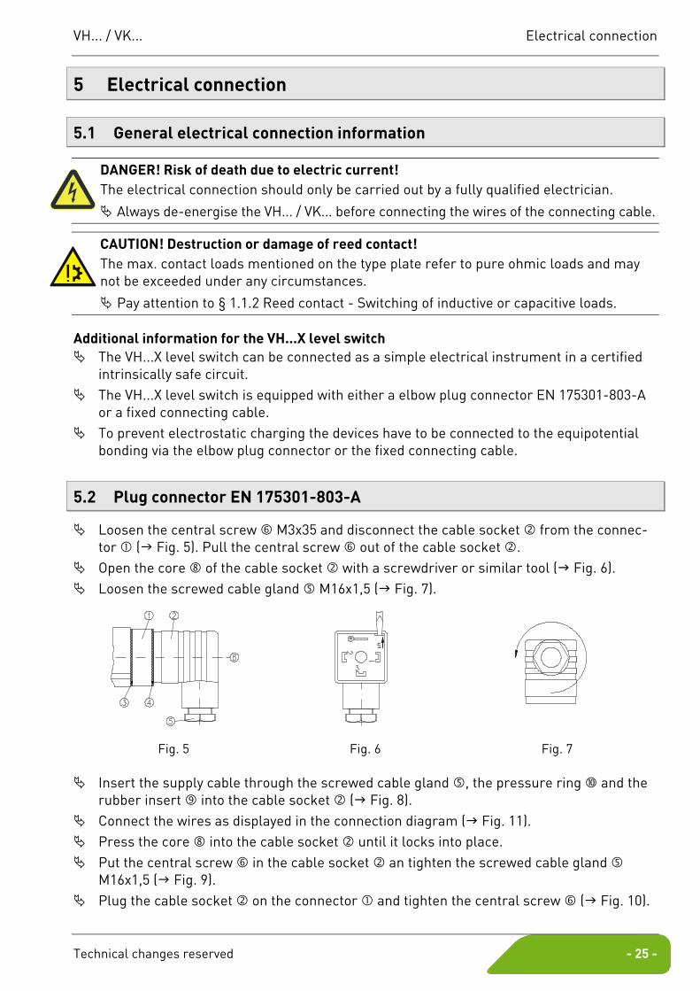
Loosen the central screw M3x35 and disconnect the cable socket from the connec-tor ( Fig. 5). Pull the central screw out of the cable socket .
Open the core of the cable socket with a screwdriver or similar tool ( Fig. 6). Loosen the screwed cable gland M16x1,5 ( Fig. 7).
Fig. 5 Fig. 6 Fig. 7
Insert the supply cable through the screwed cable gland , the pressure ring and the rubber insert into the cable socket ( Fig. 8).
Connect the wires as displayed in the connection diagram ( Fig. 11). Press the core into the cable socket until it locks into place. Put the central screw in the cable socket an tighten the screwed cable gland
M16x1,5 ( Fig. 9). Plug the cable socket on the connector and tighten the central screw ( Fig. 10).
Electrical connection VH... / VK...
- 26 - © SIKA • Ea1300_LevelSwitch 08/2013
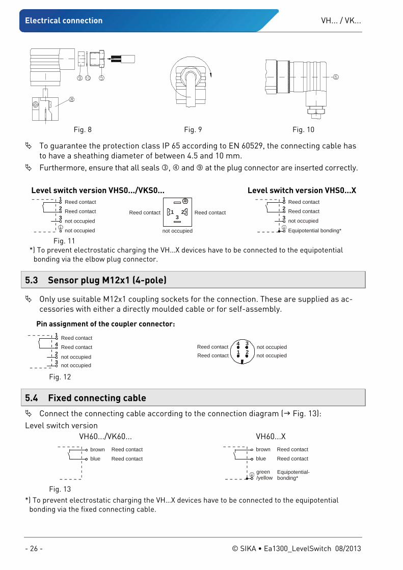
Fig. 8 Fig. 9 Fig. 10
To guarantee the protection class IP 65 according to EN 60529, the connecting cable has to have a sheathing diameter of between 4.5 and 10 mm.
Furthermore, ensure that all seals , and at the plug connector are inserted correctly.
Level switch version VHS0.../VKS0... Level switch version VHS0...X Reed contact
Reed contact
not occupied
not occupied
1
2
3Reed contactReed contact
not occupied
13
2
Reed contact
Reed contact
not occupied
Equipotential bonding*
1
2
3
Fig. 11 *) To prevent electrostatic charging the VH…X devices have to be connected to the equipotential
bonding via the elbow plug connector.
5.3 Sensor plug M12x1 (4-pole)
Only use suitable M12x1 coupling sockets for the connection. These are supplied as ac-cessories with either a directly moulded cable or for self-assembly.
5.4 Fixed connecting cable
Connect the connecting cable according to the connection diagram ( Fig. 13): Level switch version
Pin assignment of the coupler connector:
Reed contact
Reed contact
not occupiednot occupied
1
4
23
Reed contactReed contact
not occupiednot occupied2
4 31
Fig. 12
VH60.../VK60... VH60...X brown
blue
Reed contact
Reed contact
Equipotential-bonding*
brown
blue
Reed contact
Reed contact
green/yellow
Fig. 13 *) To prevent electrostatic charging the VH…X devices have to be connected to the equipotential
bonding via the fixed connecting cable.
VH... / VK... Adjusting the switching unit
Technical changes reserved - 27 -
6 Adjusting the switching unit
Important notices! Adjustment of the switching unit is not required if a desired ex works switching point set-ting has been agreed with the customer. If there are no arrows on the switching unit, the Adjustment of the type of contact and the switching point is not permitted.
6.1 Type of contact
The switching unit of the control switch enables two types of contact:
1. Normally open contact: “RED” arrow on the switching unit
2. Normally closed contact: “WHITE” or “BLUE” arrow on the switching unit
The following table explains the two types of contact:
Type of contact Setting Filling level Electrical contact rising closing
Normally open RED arrow falling opening
rising opening Normally closed
WHITE or BLUE arrow falling closing
Unless otherwise requested by the customer, the switching is factory set as a normally open contact.
6.2 Level switch version VH...X
WARNING! LOSS OF EXPLOSION PROTECTION! No explosion protection when adjusting the type of contact or the switching point.
For use in explosion-risk area, the type of contact or the switching point is fixed by fac-tory. Adjustment of the type of contact and the switching point is not permitted.
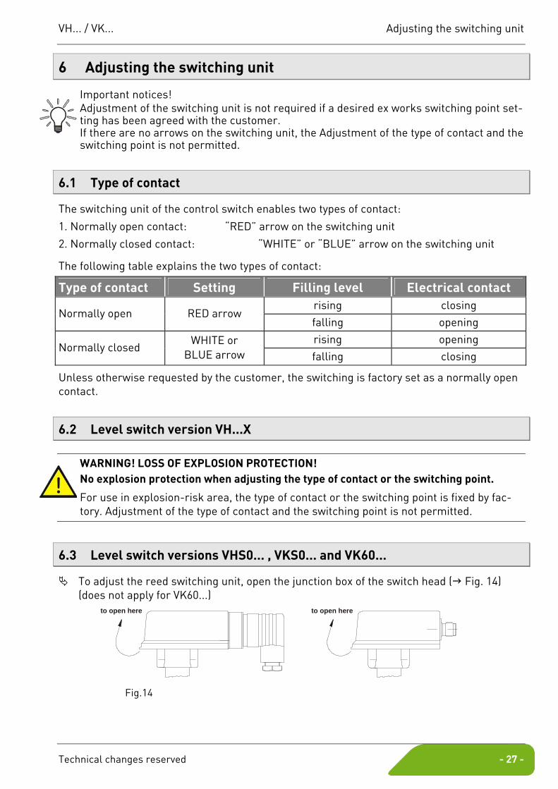
6.3 Level switch versions VHS0... , VKS0... and VK60...
To adjust the reed switching unit, open the junction box of the switch head ( Fig. 14) (does not apply for VK60...)
to open here
to open here
Fig.14
Adjusting the switching unit VH... / VK...
- 28 - © SIKA • Ea1300_LevelSwitch 08/2013
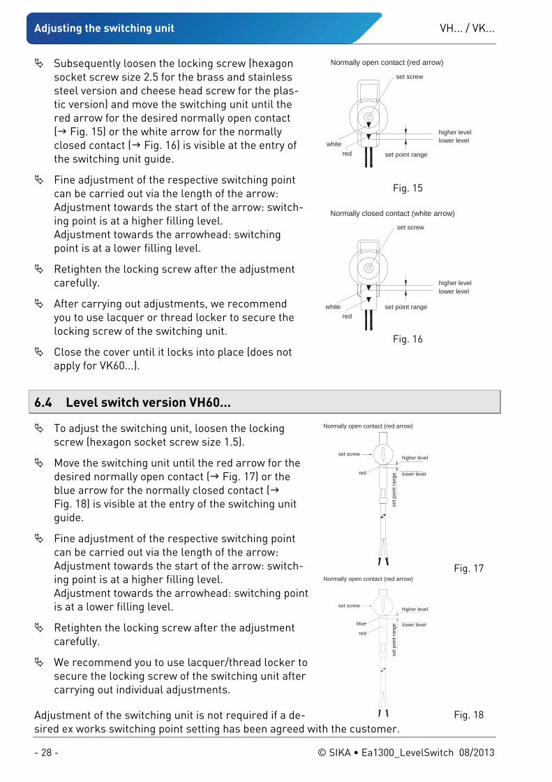
Subsequently loosen the locking screw (hexagon socket screw size 2.5 for the brass and stainless steel version and cheese head screw for the plas-tic version) and move the switching unit until the red arrow for the desired normally open contact ( Fig. 15) or the white arrow for the normally closed contact ( Fig. 16) is visible at the entry of the switching unit guide.
Fine adjustment of the respective switching point can be carried out via the length of the arrow: Adjustment towards the start of the arrow: switch-ing point is at a higher filling level. Adjustment towards the arrowhead: switching point is at a lower filling level.
Retighten the locking screw after the adjustment carefully.
After carrying out adjustments, we recommend you to use lacquer or thread locker to secure the locking screw of the switching unit.
Close the cover until it locks into place (does not apply for VK60...).
6.4 Level switch version VH60...
To adjust the switching unit, loosen the locking screw (hexagon socket screw size 1.5).
Move the switching unit until the red arrow for the desired normally open contact ( Fig. 17) or the blue arrow for the normally closed contact ( Fig. 18) is visible at the entry of the switching unit guide.
Fine adjustment of the respective switching point can be carried out via the length of the arrow: Adjustment towards the start of the arrow: switch-ing point is at a higher filling level. Adjustment towards the arrowhead: switching point is at a lower filling level.
Retighten the locking screw after the adjustment carefully.
We recommend you to use lacquer/thread locker to secure the locking screw of the switching unit after carrying out individual adjustments.
Adjustment of the switching unit is not required if a de-sired ex works switching point setting has been agreed with the customer.
higher levellower level
set point range
set screw
redwhite
Normally open contact (red arrow)
Fig. 15
higher levellower level
set point range
set screw
redwhite
Normally closed contact (white arrow)
Fig. 16
higher level
lower level
set p
oint
rang
e
set screw
red
Normally open contact (red arrow)
Fig. 17
blue
higher level
lower level
set p
oint
rang
e
set screw
red
Normally open contact (red arrow)
Fig. 18
VH... / VK... Maintenance and Cleaning
Technical changes reserved - 29 -
7 Maintenance and Cleaning
Maintenance: The level switch VH... / VK... is maintenance-free and cannot be repaired by the user. In case of a defect, the device must be replaced or sent back the manufacturer for repair.
CAUTION! Material damage! When opening the device, critical parts or components can be damaged.
Never open the device.
Cleaning: Clean the VH... / VK... with a dry or slightly damp lint-free cloth. Do not use sharp objects or aggressive agents for cleaning
8 Decommissioning and Disposal
CAUTION! Risk of injury! Never remove a level switch or its body from a system under pressure.
Make sure that the plant is shut down professionally.
Before disassembly: Prior to disassembly, ensure that
the equipment is switched off and is in a safe and de-energised state. the equipment is depressurised and has cooled down.
Disassembly: Remove the electrical connectors. Remove the VH... / VK... using suitable tools.
Disposal:
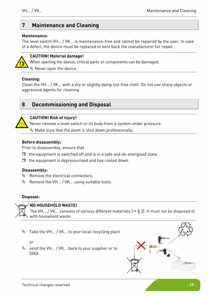
NO HOUSEHOLD WASTE! The VH... / VK... consists of various different materials ( § 3). It must not be disposed of with household waste.
Take the VH... / VK... to your local recycling plant or
send the VH... / VK... back to your supplier or to SIKA.
+p
Technical data VH... / VK...
- 30 - © SIKA • Ea1300_LevelSwitch 08/2013
9 Technical data
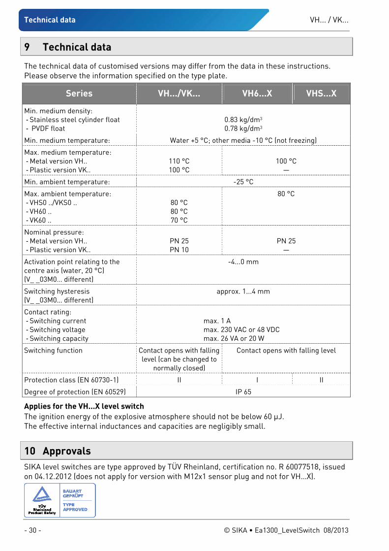
The technical data of customised versions may differ from the data in these instructions. Please observe the information specified on the type plate.
Series VH.../VK... VH6...X VHS...X
Min. medium density: - Stainless steel cylinder float - PVDF float
0.83 kg/dm3 0.78 kg/dm3
Min. medium temperature: Water +5 °C; other media -10 °C (not freezing)
Max. medium temperature: - Metal version VH.. - Plastic version VK..
110 °C 100 °C
100 °C
—
Min. ambient temperature: -25 °C
Max. ambient temperature: - VHS0 ../VKS0 .. - VH60 .. - VK60 ..
80 °C 80 °C 70 °C
80 °C
Nominal pressure: - Metal version VH.. - Plastic version VK..
PN 25 PN 10
PN 25
—
Activation point relating to the centre axis (water, 20 °C) (V_ _03M0… different)
-4...0 mm
Switching hysteresis (V_ _03M0… different)
approx. 1...4 mm
Contact rating: - Switching current - Switching voltage - Switching capacity
max. 1 A max. 230 VAC or 48 VDC max. 26 VA or 20 W
Switching function Contact opens with falling level (can be changed to
normally closed)
Contact opens with falling level
Protection class (EN 60730-1) II I II
Degree of protection (EN 60529) IP 65
Applies for the VH...X level switch The ignition energy of the explosive atmosphere should not be below 60 μJ. The effective internal inductances and capacities are negligibly small.
10 Approvals SIKA level switches are type approved by TÜV Rheinland, certification no. R 60077518, issued on 04.12.2012 (does not apply for version with M12x1 sensor plug and not for VH…X).

VH... / VK... EC declaration of conformity
Technical changes reserved - 31 -
11 EC declaration of conformity
VH... / VK...
- 32 - © SIKA • Ea1300_LevelSwitch 08/2013
Mechanical measuring instruments
Flow measuring instruments
Electronic measuring- & calibration instruments
SIKA Dr.Siebert & Kühn GmbH & Co. KG Struthweg 7–9 D-34260 Kaufungen Germany
℡ +49 (0)5605 803-0 +49 5605 803-54
[email protected] www.sika.net
Conservez cette notice d'utilisation pour vous y reporter. Joignez cette notice d'utilisation à la vente de l'appareil. ©
SIK
A •
Ea1
300_
Leve
lSw
itch
08/
2013
.
Contrôleur de niveau Séries VH... / VK...
Notice d'utilisation ( Traduction )
Betriebsanleitung ....................................................Seite 1 - 16
Operating manual .................................................. page 17 - 32
Notice d'utilisation................................................. page 33 - 48
VH... / VK...
- 34 - © SIKA • Ea1300_LevelSwitch 08/2013
Sommaire page
0 Indications sur la notice d'utilisation..........................................................................35 1 Description de l'appareil .............................................................................................36 1.1 Utilisation conforme..................................................................................................36 1.1.1 Modèle de contrôleur de niveau VH...X ................................................................37 1.1.2 Contact reed - Commuter de charges inductives ou capacitaires ......................37 1.2 Exclusion de garantie................................................................................................37
2 Consignes de sécurité .................................................................................................38 2.1 Personnel qualifié .....................................................................................................38 2.2 Instructions spéciales de sécurité :..........................................................................38 2.3 Conditions supplémentaires pour le contrôleur de niveau VH...X ...........................39
3 Spécification des matériaux des composants mouillés .............................................39 4 Montage du contrôleur de niveau ...............................................................................40 4.1 Généralités ................................................................................................................40
5 Branchement électrique .............................................................................................41 5.1 Généralités sur le branchement électrique .............................................................41 5.2 Connecteur coudé EN 175301-803-A........................................................................41 5.3 Prise du capteur M12x1 (à 4 pôles)...........................................................................42 5.4 Câble de connexion fixe ............................................................................................42
6 Régler l’unité de commutation ...................................................................................43 6.1 Type de contact .........................................................................................................43 6.2 Modèle de contrôleur de niveau VH...X.....................................................................43 6.3 Modèle de contrôleur de niveau VHS0... , VKS0... et VK60... ....................................43 6.4 Modèle de contrôleur de niveau VH60... ...................................................................44
7 Entretien et nettoyage.................................................................................................45 8 Démontage et élimination...........................................................................................45 9 Données techniques....................................................................................................46 10 Homologations ............................................................................................................46 11 Déclaration de conformité UE.....................................................................................47
Note sur la protection des droits d'auteur : Toute communication ou reproduction de ce notice d'utilisation, toute exploitation ou communication de son contenu sont interdites, sauf autorisation expresse. Tout manquement à cette règle est illicite et expose son auteur au versement de dommages et intérêts. Tous droits réservés pour le cas de la délivrance d'un brevet, d'un modèle d'utilité ou d'un modèle de présentation.
VH... / VK... Indications sur la notice d'utilisation
Sous réserve de modifications techniques - 35 -
0 Indications sur la notice d'utilisation
• La notice d'utilisation est destinée à un personnel formé et spécialisé. • Avant chaque étape de travail, lisez attentivement les indications correspondantes
dans l'ordre indiqué. • Lisez particulièrement attentivement le chapitre « Consignes de sécurité ».
Si vous avez des problèmes ou des questions, adressez-vous à votre fournisseur ou directe-ment à
Dr. Siebert & Kühn GmbH & Co. KG Struthweg 7-9 • D - 34260 Kaufungen ℡ 05605-803 0 • 05605-803 54
[email protected] • www.sika.net
Signes et symboles de sécurité utilisés :
DANGER ! Danger de mort par électrocution ! Ce signe indique un danger susceptible d'entraîner de graves blessures ou même la mort.
AVERTISSEMENT ! / ATTENTION ! Risque de blessure ! Ce signe indique un danger susceptible d'entraîner des blessures corporelles, des dommages personnels ou des dégâts matériels considérables.
+p
ATTENTION ! Risque de blessure par surpression ! Ce signe indique un danger par suite de surpression dans un appareil.
ATTENTION ! DEGATS MATERIELS ! Ce signe indique des manipulations qui peuvent provoquer des dégâts matériels et à l'envi-ronnement.
SUIVEZ LA NOTICE D'UTILISATION !
INDICATION ! Ce symbole indique des indications, astu-ces ou informations importants.
PAS DE DECHET MENAGER ! Ne jetez pas cet appareil avec les dé-chets ménagers.
Prenez note et suivez attentivement les in-formations qu'il contient.
Suivez les instructions et étapes de mani-pulation. Données dans l'ordre.
Prenez note et suivez attentivement les in-formations qu'il contient.
Renvoi à un autre chapitre, document ou source.
• Point d'énumération.
Description de l'appareil VH... / VK...
- 36 - © SIKA • Ea1300_LevelSwitch 08/2013
1 Description de l'appareil
Les contrôleurs de niveau SIKA sont destinés au contrôle des minima et maxima des niveaux de liquides.
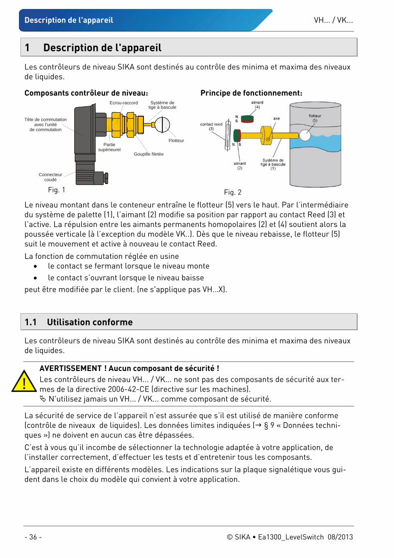
Composants contrôleur de niveau:
Tête de commutation avec l’unité
de commutation
Partiesupérieurel
Ecrou-raccord
Goupille filetèe
Système de tige à bascule
Flotteur
Connecteurcoudé
Fig. 1
Principe de fonctionnement:
Fig. 2
Le niveau montant dans le conteneur entraîne le flotteur (5) vers le haut. Par l’intermédiaire du système de palette (1), l’aimant (2) modifie sa position par rapport au contact Reed (3) et l’active. La répulsion entre les aimants permanents homopolaires (2) et (4) soutient alors la poussée verticale (à l’exception du modèle VK..). Dès que le niveau rebaisse, le flotteur (5) suit le mouvement et active à nouveau le contact Reed.
La fonction de commutation réglée en usine • le contact se fermant lorsque le niveau monte • le contact s’ouvrant lorsque le niveau baisse
peut être modifiée par le client. (ne s'applique pas VH…X).
1.1 Utilisation conforme
Les contrôleurs de niveau SIKA sont destinés au contrôle des minima et maxima des niveaux de liquides.
AVERTISSEMENT ! Aucun composant de sécurité ! Les contrôleurs de niveau VH... / VK... ne sont pas des composants de sécurité aux ter-mes de la directive 2006-42-CE (directive sur les machines).
N'utilisez jamais un VH... / VK... comme composant de sécurité.
La sécurité de service de l’appareil n’est assurée que s’il est utilisé de manière conforme (contrôle de niveaux de liquides). Les données limites indiquées ( § 9 « Données techni-ques ») ne doivent en aucun cas être dépassées.
C’est à vous qu’il incombe de sélectionner la technologie adaptée à votre application, de l’installer correctement, d’effectuer les tests et d’entretenir tous les composants.
L’appareil existe en différents modèles. Les indications sur la plaque signalétique vous gui-dent dans le choix du modèle qui convient à votre application.
VH... / VK... Description de l'appareil
Sous réserve de modifications techniques - 37 -
1.1.1 Modèle de contrôleur de niveau VH...X
Le dernier caractère de la référence des contrôleurs de niveau conçus pour le domaine Ex est un « X » ( plaque signalétique). Les contrôleurs ont été soumis à une évaluation du ris-que d’allumage selon DIN EN 13463-1 : 2002 et amendement 1 : 2003. Ils ne représentent pas en eux-mêmes une source d’allumage potentielle. Ils ne sont donc pas soumis à la di-rective 94/9/CE.
L’unité de commutation est constituée de matériel électrique simple pour branchement sur circuit à sécurité intrinsèque dans le sens de la norme DIN EN 60079 : 2007. Les inductions et capacités internes sont négligeables.
Les contrôleurs de niveau de la série VH...X sont conçus pour l’emploi dans des domaines à atmosphère potentiellement explosive. L’énergie d’allumage de l’atmosphère potentielle-ment explosive ne doit pas être inférieure à 60 μJ.
Tenir compte de la séparation des zones : Les contrôleurs de niveau de la série VH...X sont conçu tel que l’intérieur de la conduite, où se trouve le flotteur, peut être soumis en permanence, pendant une longue période de temps ou souvent à une atmosphère potentiellement explosive (Zone 0).
En service normal, une atmosphère potentiellement explosive ne doit prévaloir que de temps en temps à l’extérieur de la conduite, au niveau du raccordement du contrôleur de niveau (Zone 1). Une déclaration du fabricant est à disposition.
1.1.2 Contact reed - Commuter de charges inductives ou capacitaires
ATTENTION ! Destruction ou endommagement du contact reed ! Veuillez respecter la charge max. des contacts, indiquée sur la plaque signalétique !
Les charges max. (tensions de commutation, courant de commutation et puissance de rupture), qui sont indiquées sur la plaque signalétique, sont uniquement valables pour des charges purement ohmiques et ne doivent en aucun cas être dépassées
Des pics de tension et de courant élevés surviennent surtout lors de la commutation de charges inductives ou capacitives (par exemple bobine, condensateurs). Même des surchar-ges de courte durée peuvent détruire le contact reed (soudure des contacts) ou l'endomma-ger (durée d'utilisation réduite).
Pour votre application, utilisez uniquement des mesures de sécurité adaptées et contrôlées.
Mesure de protection de le branchement électrique de contacts reed : Les circuits de protection suivants sont généralement possibles : résistances de limitation de courant, circuits RC, diodes de roue libre, diodes de suppression, varistors ou des com-binaisons de ces éléments.
Contrôlez l'efficacité de la mesure de sécurité choisie pour le cas spécifique de la charge de votre application.
1.2 Exclusion de garantie
Aucune garantie n'est assurée pour ce qui concerne les dommages et les incidents d'exploi-tation, résultant d'erreurs de montage, d'une utilisation non-conforme ou d'un non-respect de ce mode d'emploi.
Consignes de sécurité VH... / VK...
- 38 - © SIKA • Ea1300_LevelSwitch 08/2013
2 Consignes de sécurité
Avant d'installer VH... / VK..., lisez attentivement cette notice d'utilisation. Si les instructions qui y sont contenues, en particulier les instructions de sécurité, ne sont pas respectées, cela risque de mettre en danger les personnes, l'environnement, les appareils et les systèmes.
Les VH... / VK... correspondent à l'état actuel de la technique. Cela concerne la précision du point de commutation, le mode de fonctionnement et la sécurité du fonctionnement de l'appareil.
Pour garantir un fonctionnement sûr, un comportement professionnel et axé sur la sécurité est nécessaire de la part de l'utilisateur.
SIKA garantit une assistance en personne ou via la documentation correspondante pour l'uti-lisation des produits. Le client vérifie l'utilisabilité du produit sur la base de nos informations techniques. Avec ce contrôle, risque et danger sont transmis à nos clients : notre garantie prend fin.
2.1 Personnel qualifié
Le personnel chargé du montage, de l'utilisation et de la maintenance du VH... / VK... doit avoir reçu une qualification adéquate. Cela peut se faire par une formation scolaire ou continue correspondante. Le contenu du présent notice d'utilisation doit être connu du personnel et lui être acces-sible à tout moment.
Seul un électricien est autorisé à effectuer le branchement électrique.
2.2 Instructions spéciales de sécurité :
Pour tout travail, les prescriptions nationales en vigueur de sécurité et de prévention des accidents doivent être respectées sur le lieu de travail. Les prescriptions internes exis-tantes de l'exploitant doivent être prises en considération même si elles ne sont pas spé-cifiées dans ce document.
Afin d’éviter les dégâts du contrôleur de niveau et de l'installation à contrôler, il faut tenir compte du fait que les contrôleurs de niveau SIKA sont exclusivement conçus pour le contrôle de niveaux de liquides.
Il faut absolument respecter les indications de montage du contrôleur de niveau. Avant de monter le contrôleur de niveau, il faut s’assurer que tous les matériaux du
contrôleur de niveau sont résistants mécaniquement et chimiquement aux milieux à sur-veiller et à tous les impacts extérieurs.
S’assurer que le milieu est exempt de particules magnétiques et que la valeur minimale de densité ( § 9« Données techniques ») est respectée.
Prévenir le gel du milieu avec des mesures adéquates. Si le contrôleur de niveau doit être soumis plus tard à des températures environnantes <4 °C, il ne faut pas l’opérer en premier lieu, pour un test par ex., avec de l’eau pure. L’eau résiduelle dans le contrôleur de niveau pourrait entraîner des dégâts dus au gel.
Compte tenu de la résistance des matériaux, aucunes graisses, huiles, etc. ne doivent être utilisées lors du montage du contrôleur de niveau de la série VH... .
Veillez à ce que la pression de service max. mentionnée ne soit pas dépassée. N’enlevez en aucun cas, un contrôleur de niveau ou sa partie supérieure, d’une installa-
tion placée sous pression.
VH... / VK... Spécification des matériaux des composants mouillés
Sous réserve de modifications techniques - 39 -
Si le milieu à contrôler présente une température très élevée, les contrôleurs de niveau et leurs raccords deviennent aussi très chauds. Evitez tout contact et éloignez les objets sensibles aux températures élevées.
Protégez le contrôleur de niveau des champs magnétiques externes dans l’environnement proche car ils peuvent altérer le fonctionnement de l'appareil.
Les spécifications des modèles spéciaux (modèles personnalisés spécifiques au client) peuvent différer des données de ce mode d’emploi. Veuillez observer les données sur la plaque signalétique.
AVERTISSEMENT ! Tension électrique, danger de mort ! Effectuer toujours le montage électrique sans tension avant de raccorder les fils sur le circuit.
Les plaques signalétiques ou autres indications sur l’appareil ne doivent être ni enlevées ni rendues illisibles, sinon la garantie et la responsabilité du fabricant expirent.
2.3 Conditions supplémentaires pour le contrôleur de niveau VH...X
Le contrôleur de niveau ne doit être mis en contact qu’avec des milieux possédant une température d’allumage minimale >135 °C et une énergie d’allumage >60 μJ.
Au cours de l’installation et avant la mise en service, s’assurer que les raccords mécani-ques sont étanches.
Il faut tenir compte de l’étanchéité des éléments de vissage lors de la détermination des zones. Selon les conditions d’application, il peut être nécessaire de vérifier régulièrement l’étanchéité des éléments de vissage.
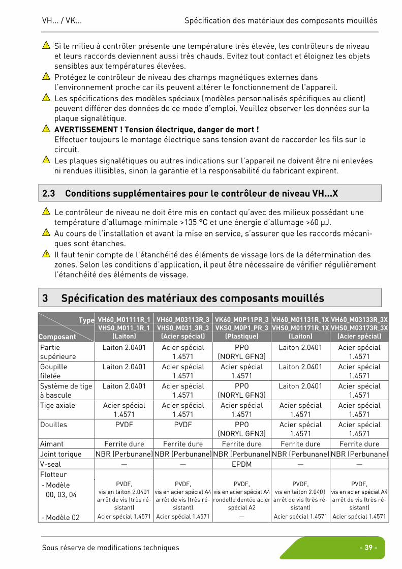
3 Spécification des matériaux des composants mouillés
Type
Composant
VH60_M01111R_1 VHS0_M011_1R_1
(Laiton)
VH60_M03113R_3 VHS0_M031_3R_3
(Acier spécial)
VK60_M0P11PR_3 VKS0_M0P1_PR_3
(Plastique)
VH60_M01131R_1X VHS0_M01171R_1X
(Laiton)
VH60_M03133R_3X VHS0_M03173R_3X
(Acier spécial)
Partie supérieure
Laiton 2.0401 Acier spécial 1.4571
PPO (NORYL GFN3)
Laiton 2.0401 Acier spécial 1.4571
Goupille filetée
Laiton 2.0401 Acier spécial 1.4571
Acier spécial 1.4571
Laiton 2.0401 Acier spécial 1.4571
Système de tige à bascule
Laiton 2.0401 Acier spécial 1.4571
PPO (NORYL GFN3)
Laiton 2.0401 Acier spécial 1.4571
Tige axiale Acier spécial 1.4571
Acier spécial 1.4571
Acier spécial 1.4571
Acier spécial 1.4571
Acier spécial 1.4571
Douilles PVDF PVDF PPO (NORYL GFN3)
Acier spécial 1.4571
Acier spécial 1.4571
Aimant Ferrite dure Ferrite dure Ferrite dure Ferrite dure Ferrite dure Joint torique NBR (Perbunane) NBR (Perbunane) NBR (Perbunane) NBR (Perbunane) NBR (Perbunane) V-seal — — EPDM — — Flotteur - Modèle
00, 03, 04 PVDF,
vis en laiton 2.0401 arrêt de vis (très ré-
sistant)
PVDF, vis en acier spécial A4 arrêt de vis (très ré-
sistant)
PVDF, vis en acier spécial A4 rondelle dentée acier
spécial A2
PVDF, vis en laiton 2.0401
arrêt de vis (très ré-sistant)
PVDF, vis en acier spécial A4 arrêt de vis (très ré-
sistant)
- Modèle 02 Acier spécial 1.4571 Acier spécial 1.4571 — Acier spécial 1.4571 Acier spécial 1.4571
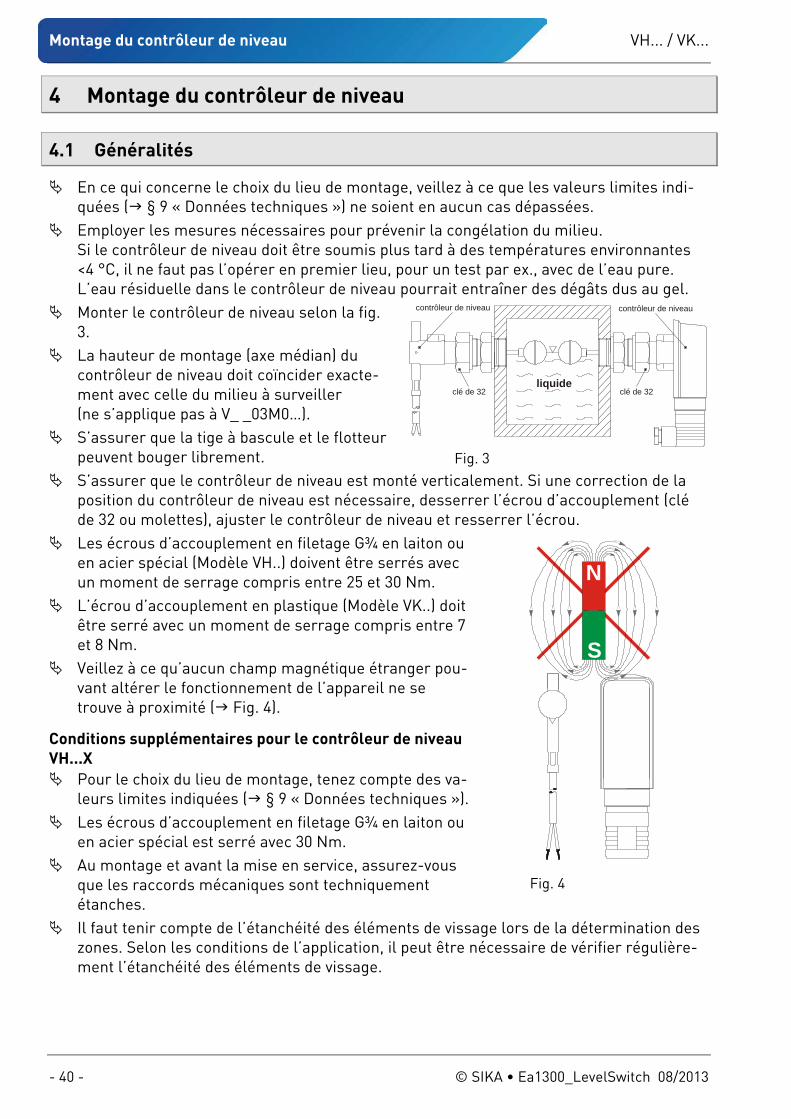
Montage du contrôleur de niveau VH... / VK...
- 40 - © SIKA • Ea1300_LevelSwitch 08/2013
4 Montage du contrôleur de niveau
4.1 Généralités
En ce qui concerne le choix du lieu de montage, veillez à ce que les valeurs limites indi-quées ( § 9 « Données techniques ») ne soient en aucun cas dépassées.
Employer les mesures nécessaires pour prévenir la congélation du milieu. Si le contrôleur de niveau doit être soumis plus tard à des températures environnantes <4 °C, il ne faut pas l’opérer en premier lieu, pour un test par ex., avec de l’eau pure. L’eau résiduelle dans le contrôleur de niveau pourrait entraîner des dégâts dus au gel.
Monter le contrôleur de niveau selon la fig. 3.
La hauteur de montage (axe médian) du contrôleur de niveau doit coïncider exacte-ment avec celle du milieu à surveiller (ne s’applique pas à V_ _03M0…).
S’assurer que la tige à bascule et le flotteur peuvent bouger librement.
S’assurer que le contrôleur de niveau est monté verticalement. Si une correction de la position du contrôleur de niveau est nécessaire, desserrer l’écrou d’accouplement (clé de 32 ou molettes), ajuster le contrôleur de niveau et resserrer l’écrou.
Les écrous d’accouplement en filetage G¾ en laiton ou en acier spécial (Modèle VH..) doivent être serrés avec un moment de serrage compris entre 25 et 30 Nm.
L’écrou d’accouplement en plastique (Modèle VK..) doit être serré avec un moment de serrage compris entre 7 et 8 Nm.
Veillez à ce qu’aucun champ magnétique étranger pou-vant altérer le fonctionnement de l’appareil ne se trouve à proximité ( Fig. 4).
Conditions supplémentaires pour le contrôleur de niveau VH...X
Pour le choix du lieu de montage, tenez compte des va-leurs limites indiquées ( § 9 « Données techniques »).
Les écrous d’accouplement en filetage G¾ en laiton ou en acier spécial est serré avec 30 Nm.
Au montage et avant la mise en service, assurez-vous que les raccords mécaniques sont techniquement étanches.
Il faut tenir compte de l’étanchéité des éléments de vissage lors de la détermination des zones. Selon les conditions de l’application, il peut être nécessaire de vérifier régulière-ment l’étanchéité des éléments de vissage.
clé de 32clé de 32
contrôleur de niveau
liquide
contrôleur de niveau
Fig. 3
N
S
Fig. 4
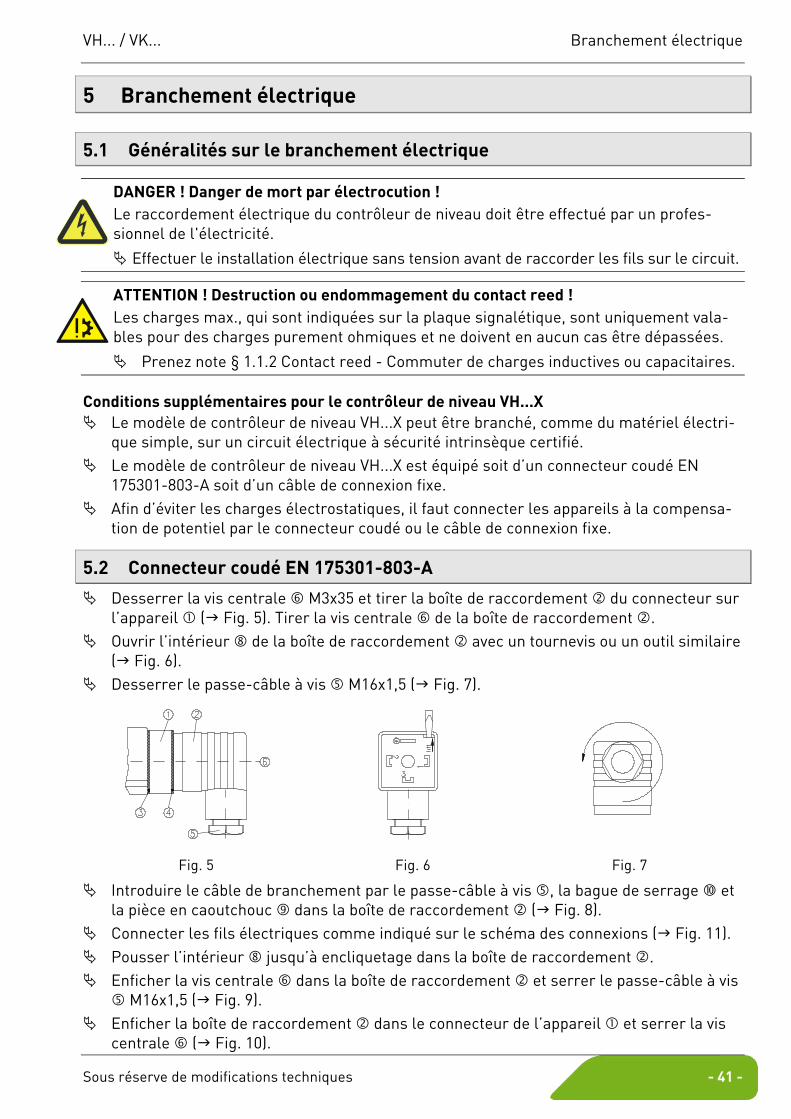
VH... / VK... Branchement électrique
Sous réserve de modifications techniques - 41 -
5 Branchement électrique
5.1 Généralités sur le branchement électrique
DANGER ! Danger de mort par électrocution ! Le raccordement électrique du contrôleur de niveau doit être effectué par un profes-sionnel de l'électricité.
Effectuer le installation électrique sans tension avant de raccorder les fils sur le circuit.
ATTENTION ! Destruction ou endommagement du contact reed ! Les charges max., qui sont indiquées sur la plaque signalétique, sont uniquement vala-bles pour des charges purement ohmiques et ne doivent en aucun cas être dépassées.
Prenez note § 1.1.2 Contact reed - Commuter de charges inductives ou capacitaires.
Conditions supplémentaires pour le contrôleur de niveau VH...X Le modèle de contrôleur de niveau VH...X peut être branché, comme du matériel électri-
que simple, sur un circuit électrique à sécurité intrinsèque certifié. Le modèle de contrôleur de niveau VH...X est équipé soit d’un connecteur coudé EN
175301-803-A soit d’un câble de connexion fixe. Afin d’éviter les charges électrostatiques, il faut connecter les appareils à la compensa-
tion de potentiel par le connecteur coudé ou le câble de connexion fixe.
5.2 Connecteur coudé EN 175301-803-A
Desserrer la vis centrale M3x35 et tirer la boîte de raccordement du connecteur sur l’appareil ( Fig. 5). Tirer la vis centrale de la boîte de raccordement .
Ouvrir l’intérieur de la boîte de raccordement avec un tournevis ou un outil similaire ( Fig. 6).
Desserrer le passe-câble à vis M16x1,5 ( Fig. 7).
Fig. 5 Fig. 6 Fig. 7
Introduire le câble de branchement par le passe-câble à vis , la bague de serrage et la pièce en caoutchouc dans la boîte de raccordement ( Fig. 8).
Connecter les fils électriques comme indiqué sur le schéma des connexions ( Fig. 11). Pousser l’intérieur jusqu’à encliquetage dans la boîte de raccordement . Enficher la vis centrale dans la boîte de raccordement et serrer le passe-câble à vis
M16x1,5 ( Fig. 9). Enficher la boîte de raccordement dans le connecteur de l’appareil et serrer la vis
centrale ( Fig. 10).
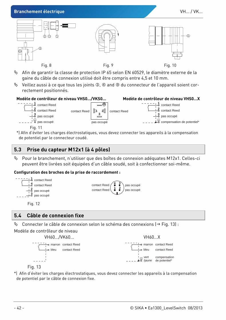
Branchement électrique VH... / VK...
- 42 - © SIKA • Ea1300_LevelSwitch 08/2013
Fig. 8 Fig. 9 Fig. 10
Afin de garantir la classe de protection IP 65 selon EN 60529, le diamètre externe de la gaine du câble de connexion utilisé doit être compris entre 4,5 et 10 mm.
Veillez aussi à ce que tous les joints , and du connecteur de l’appareil soient cor-rectement positionnés.
Modèle de contrôleur de niveau VHS0.../VKS0... Modèle de contrôleur de niveau VHS0...X contact Reed
contact Reed
pas occupé
pas occupé
1
2
3contact Reedcontact Reed
pas occupé
13
2
contact Reed
contact Reed
pas occupé
compensation de potentiel*
1
2
3
Fig. 11 *) Afin d’éviter les charges électrostatiques, vous devez connecter les appareils à la compensation
de potentiel par le connecteur coudé.
5.3 Prise du capteur M12x1 (à 4 pôles)
Pour le branchement, n’utiliser que des boîtes de connexion adéquates M12x1. Celles-ci peuvent être livrées soit équipées d’un câble soudé, soit à confectionner soi-même.
5.4 Câble de connexion fixe
Connecter le câble de connexion selon le schéma des connexions ( Fig. 13) : Modèle de contrôleur de niveau
Configuration des broches de la prise de raccordement :
contact Reed
contact Reed
pas occupépas occupé
1
4
23
contact Reedcontact Reed
pas occupépas occupé2
4 31
Fig. 12
VH60.../VK60... VH60...X marron
bleu
contact Reed
contact Reed
compensationde potentiel*
marron
bleu
contact Reed
contact Reed
vert/jaune
Fig. 13 *) Afin d’éviter les charges électrostatiques, vous devez connecter les appareils à la compensation
de potentiel par le câble de connexion fixe.
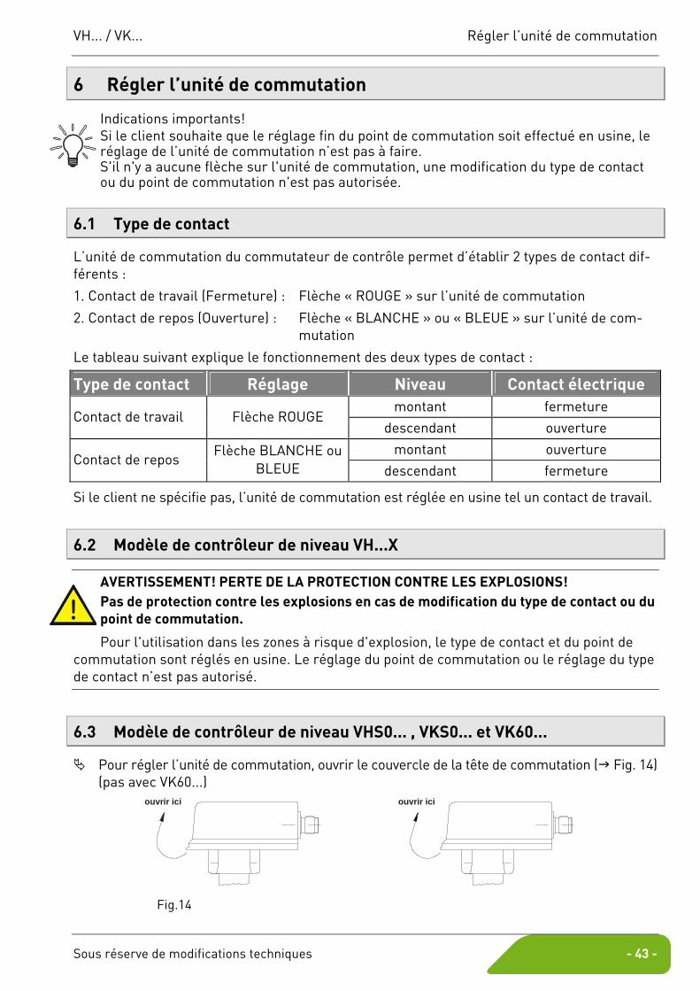
VH... / VK... Régler l’unité de commutation
Sous réserve de modifications techniques - 43 -
6 Régler l’unité de commutation
Indications importants! Si le client souhaite que le réglage fin du point de commutation soit effectué en usine, le réglage de l’unité de commutation n’est pas à faire. S'il n'y a aucune flèche sur l'unité de commutation, une modification du type de contact ou du point de commutation n'est pas autorisée.
6.1 Type de contact
L’unité de commutation du commutateur de contrôle permet d’établir 2 types de contact dif-férents :
1. Contact de travail (Fermeture) : Flèche « ROUGE » sur l’unité de commutation
2. Contact de repos (Ouverture) : Flèche « BLANCHE » ou « BLEUE » sur l’unité de com-mutation
Le tableau suivant explique le fonctionnement des deux types de contact :
Type de contact Réglage Niveau Contact électrique montant fermeture
Contact de travail Flèche ROUGE descendant ouverture
montant ouverture Contact de repos
Flèche BLANCHE ou BLEUE descendant fermeture
Si le client ne spécifie pas, l’unité de commutation est réglée en usine tel un contact de travail.
6.2 Modèle de contrôleur de niveau VH...X
AVERTISSEMENT! PERTE DE LA PROTECTION CONTRE LES EXPLOSIONS! Pas de protection contre les explosions en cas de modification du type de contact ou du point de commutation.
Pour l'utilisation dans les zones à risque d'explosion, le type de contact et du point de commutation sont réglés en usine. Le réglage du point de commutation ou le réglage du type de contact n’est pas autorisé.
6.3 Modèle de contrôleur de niveau VHS0... , VKS0... et VK60...
Pour régler l’unité de commutation, ouvrir le couvercle de la tête de commutation ( Fig. 14) (pas avec VK60...)
ouvrir ici
ouvrir ici
Fig.14
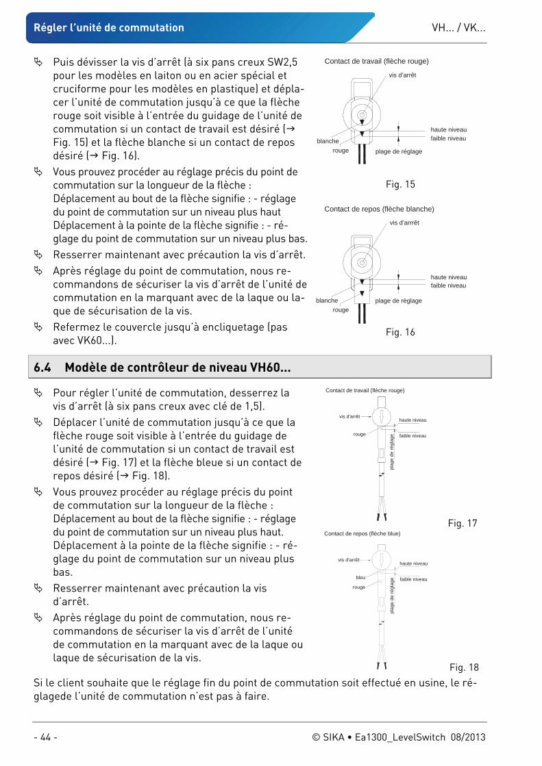
Régler l’unité de commutation VH... / VK...
- 44 - © SIKA • Ea1300_LevelSwitch 08/2013
Puis dévisser la vis d’arrêt (à six pans creux SW2,5 pour les modèles en laiton ou en acier spécial et cruciforme pour les modèles en plastique) et dépla-cer l’unité de commutation jusqu’à ce que la flèche rouge soit visible à l’entrée du guidage de l’unité de commutation si un contact de travail est désiré ( Fig. 15) et la flèche blanche si un contact de repos désiré ( Fig. 16).
Vous prouvez procéder au réglage précis du point de commutation sur la longueur de la flèche : Déplacement au bout de la flèche signifie : - réglage du point de commutation sur un niveau plus haut Déplacement à la pointe de la flèche signifie : - ré-glage du point de commutation sur un niveau plus bas.
Resserrer maintenant avec précaution la vis d’arrêt. Après réglage du point de commutation, nous re-
commandons de sécuriser la vis d’arrêt de l’unité de commutation en la marquant avec de la laque ou la-que de sécurisation de la vis.
Refermez le couvercle jusqu’à encliquetage (pas avec VK60...).
6.4 Modèle de contrôleur de niveau VH60...
Pour régler l’unité de commutation, desserrez la vis d’arrêt (à six pans creux avec clé de 1,5).
Déplacer l’unité de commutation jusqu’à ce que la flèche rouge soit visible à l’entrée du guidage de l’unité de commutation si un contact de travail est désiré ( Fig. 17) et la flèche bleue si un contact de repos désiré ( Fig. 18).
Vous prouvez procéder au réglage précis du point de commutation sur la longueur de la flèche : Déplacement au bout de la flèche signifie : - réglage du point de commutation sur un niveau plus haut. Déplacement à la pointe de la flèche signifie : - ré-glage du point de commutation sur un niveau plus bas.
Resserrer maintenant avec précaution la vis d’arrêt.
Après réglage du point de commutation, nous re-commandons de sécuriser la vis d’arrêt de l’unité de commutation en la marquant avec de la laque ou laque de sécurisation de la vis.
Si le client souhaite que le réglage fin du point de commutation soit effectué en usine, le ré-glagede l’unité de commutation n’est pas à faire.
haute niveaufaible niveau
plage de réglage
vis d’arrêt
rougeblanche
Contact de travail (flèche rouge)
Fig. 15
haute niveaufaible niveau
plage de règlage
vis d’arrrêt
rougeblanche
Contact de repos (flèche blanche)
Fig. 16
haute niveau
faible niveau
plag
e de
régl
age
vis d’arrêt
rouge
Contact de travail (flèche rouge)
Fig. 17
bleu
haute niveau
faible niveau
plag
e de
régl
age
vis d’arrêt
rouge
Contact de repos (flèche blue)
Fig. 18
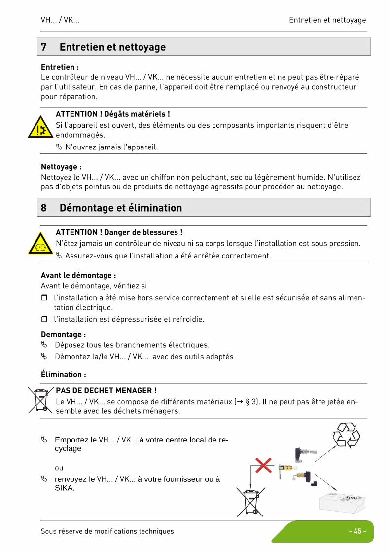
VH... / VK... Entretien et nettoyage
Sous réserve de modifications techniques - 45 -
7 Entretien et nettoyage
Entretien : Le contrôleur de niveau VH... / VK... ne nécessite aucun entretien et ne peut pas être réparé par l'utilisateur. En cas de panne, l'appareil doit être remplacé ou renvoyé au constructeur pour réparation.
ATTENTION ! Dégâts matériels ! Si l'appareil est ouvert, des éléments ou des composants importants risquent d'être endommagés.
N'ouvrez jamais l'appareil.
Nettoyage : Nettoyez le VH... / VK... avec un chiffon non peluchant, sec ou légèrement humide. N'utilisez pas d'objets pointus ou de produits de nettoyage agressifs pour procéder au nettoyage.
8 Démontage et élimination
ATTENTION ! Danger de blessures ! N’ôtez jamais un contrôleur de niveau ni sa corps lorsque l’installation est sous pression.
Assurez-vous que l'installation a été arrêtée correctement.
Avant le démontage : Avant le démontage, vérifiez si
l'installation a été mise hors service correctement et si elle est sécurisée et sans alimen-tation électrique.
l'installation est dépressurisée et refroidie.
Demontage : Déposez tous les branchements électriques. Démontez la/le VH... / VK... avec des outils adaptés
Élimination :
PAS DE DECHET MENAGER ! Le VH... / VK... se compose de différents matériaux ( § 3). Il ne peut pas être jetée en-semble avec les déchets ménagers.
Emportez le VH... / VK... à votre centre local de re-cyclage ou
renvoyez le VH... / VK... à votre fournisseur ou à SIKA.
+p
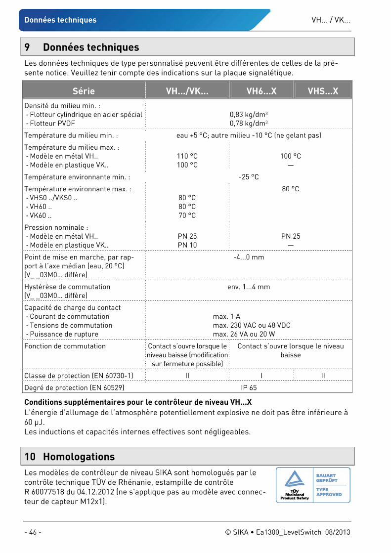
Données techniques VH... / VK...
- 46 - © SIKA • Ea1300_LevelSwitch 08/2013
9 Données techniques Les données techniques de type personnalisé peuvent être différentes de celles de la pré-sente notice. Veuillez tenir compte des indications sur la plaque signalétique.
Série VH.../VK... VH6...X VHS...X Densité du milieu min. : - Flotteur cylindrique en acier spécial - Flotteur PVDF
0,83 kg/dm3 0,78 kg/dm3
Température du milieu min. : eau +5 °C; autre milieu -10 °C (ne gelant pas)
Température du milieu max. : - Modèle en métal VH.. - Modèle en plastique VK..
110 °C 100 °C
100 °C
—
Température environnante min. : -25 °C
Température environnante max. : - VHS0 ../VKS0 .. - VH60 .. - VK60 ..
80 °C 80 °C 70 °C
80 °C
Pression nominale : - Modèle en métal VH.. - Modèle en plastique VK..
PN 25 PN 10
PN 25
—
Point de mise en marche, par rap-port à l’axe médian (eau, 20 °C) (V_ _03M0… diffère)
-4...0 mm
Hystérèse de commutation (V_ _03M0… diffère)
env. 1...4 mm
Capacité de charge du contact - Courant de commutation - Tensions de commutation - Puissance de rupture
max. 1 A max. 230 VAC ou 48 VDC max. 26 VA ou 20 W
Fonction de commutation Contact s’ouvre lorsque le niveau baisse (modification
sur fermeture possible)
Contact s’ouvre lorsque le niveau baisse
Classe de protection (EN 60730-1) II I II
Degré de protection (EN 60529) IP 65
Conditions supplémentaires pour le contrôleur de niveau VH...X L’énergie d’allumage de l’atmosphère potentiellement explosive ne doit pas être inférieure à 60 μJ. Les inductions et capacités internes effectives sont négligeables.
10 Homologations Les modèles de contrôleur de niveau SIKA sont homologués par le contrôle technique TÜV de Rhénanie, estampille de contrôle R 60077518 du 04.12.2012 (ne s'applique pas au modèle avec connec-teur de capteur M12x1).

VH... / VK... Déclaration de conformité UE
Sous réserve de modifications techniques - 47 -
11 Déclaration de conformité UE
VH... / VK...
- 48 - © SIKA • Ea1300_LevelSwitch 08/2013
Mechanische Messtechnik
Mechanical measuring instruments
Instruments mécaniques de mesure
Durchflussmesstechnik
Flow measuring instruments
Instruments de mesure de débit
Elektronische Mess- & Kalibriertechnik
Electronic measuring- & calibration instruments
Appareillages électroniques de mesure et matériels de calibration
SIKA Dr.Siebert & Kühn GmbH & Co. KG Struthweg 7–9 D-34260 Kaufungen Germany
℡ +49 (0)5605 803-0 +49 5605 803-54
[email protected] www.sika.net