Ein supraleitender Strombegrenzer für die Energieübertragung
32
Page 1 2011-05-09 © Siemens AG, Corporate Technology W. Schmidt, CT T DE HW 4 Ein supraleitender Strombegrenzer für die Energieübertragung 6. Braunschweiger Supraleiterseminar 11. - 12. Mai 2011 Wolfgang Schmidt, Hans-Peter Krämer Siemens AG, Corporate Technology Erlangen
Transcript of Ein supraleitender Strombegrenzer für die Energieübertragung
Page 1 2011-05-09 © Siemens AG, Corporate TechnologyW. Schmidt, CT T DE HW 4
Ein
supraleitender
Strombegrenzer für
die Energieübertragung
6. Braunschweiger
Supraleiterseminar11. -
12. Mai 2011
Wolfgang Schmidt, Hans-Peter Krämer Siemens AG, Corporate Technology
Erlangen
Page 2 2011-05-09 © Siemens AG, Corporate TechnologyW. Schmidt, CT T DE HW 4
The Project and the Team
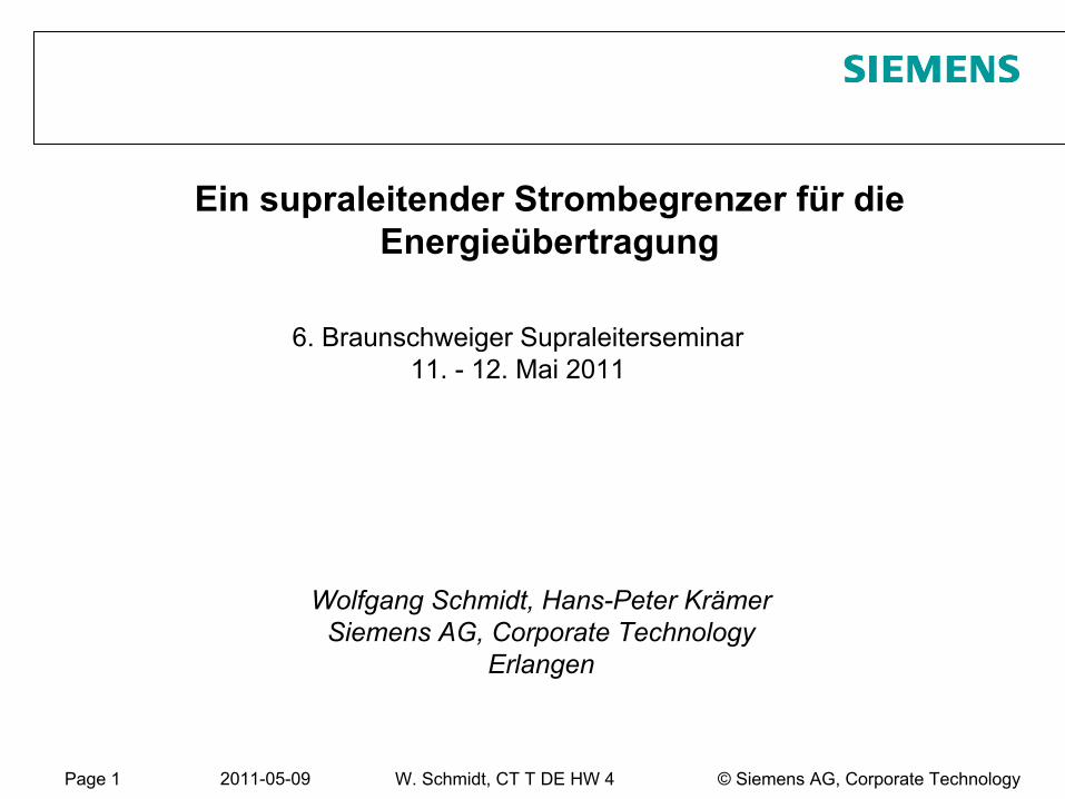
Development and InDevelopment and In--Grid Demonstration of a Transmission Grid Demonstration of a Transmission Voltage Voltage SuperLimiterSuperLimiterTMTM
Fault Current LimiterFault Current Limiter
funded by the U.S. Department of Energy funded by the U.S. Department of Energy --
National Energy National Energy Technology LaboratoryTechnology Laboratory
American Superconductor Corporation: A. Otto, E. Podtburg, J. Maguire, J. Yuan, P. Winn, W. Romanosky, B. Gamble, D. Madura.
M. Ross, D. Folts,
H. Cai, J. McNamara, T. MacDonald and A. P. Malozemoff,Siemens AG Corporate Technology:
H.-P. Kraemer, P. La Seta, W. Schmidt, M. Wohlfart, and H.-W. Neumueller,
Nexans: N. Lallouet
and F. Schmidt. Los Alamos National Laboratory:
S. Ashworth and J.O. Willis.Southern California Edison:
S. Ahmed.
Page 3 2011-05-09 © Siemens AG, Corporate TechnologyW. Schmidt, CT T DE HW 4
Outline
Introduction Needs
for
fault current
limitation
in power grids Recently
pursued
concepts
of fault current
limiters
Basics of the
resistive superconducting
fault current
limiters
(SFCL) Functional principle
Basic dimensioning
rules Basic design
of switching
elements
History
of SFCL at Siemens
Current
project: High voltage
SFCL (115 kV / 1.2 kA) funded
by
DOE Project overview: partners, schedule, specifications, status
Test sites
analyzed Design of module
and switching
elements
Manufacture
and testing
of the
first
phase
Summary
and Outlook
Page 4 2011-05-09 © Siemens AG, Corporate TechnologyW. Schmidt, CT T DE HW 4
The Need for Current Limiting Devices in Power Grids
“The most important near term energy and utility markets appear to be fault current limiters
and synchronous condensers.”
High Temperature Superconductors (HTS) Peer Presentation Document –
July 25, 2006 Navigant Consulting, Inc.
Citation from Navigant Consulting (2006):"Increasing loads on the existing power transmission system, coupled with lack of investment, lead to a growing demand for current limiting devices.
The perfect fault current limiting device features an instantaneous, self triggered transition from near zero impedance to above grid impedance in case of a fault.
→ Superconducting Fault Current Limiters (SFCL) can provide the solution. "
Page 5 2011-05-09 © Siemens AG, Corporate TechnologyW. Schmidt, CT T DE HW 4
Need for Fault Current Limitation
The fault current levels rise due toincreasing power consumption interconnection of grids to improve reliability and voltage stability
additional feeding by IPPsConventional solutions
reactors pyroelectric
limiters
no limitation, but switching off by breakers, while designing all components to carry the full fault current until the breaker opens
however, fault currents are often close to or even higher than rated breaking current of installed breakers
Wish for a current limiting device, which is …self-acting, self-restoring, fail-safe, compact, inexpensiveThe resistive HTS-FCL can meet most of these requirementsefficient use of existing grids at increased load
components with reduced ratings in new grids
Page 6 2011-05-09 © Siemens AG, Corporate TechnologyW. Schmidt, CT T DE HW 4
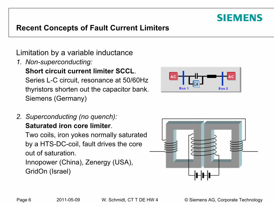
Recent Concepts of Fault Current Limiters
Limitation by a variable inductance1.
Non-superconducting:
Short circuit current limiter SCCL. Series L-C circuit, resonance at 50/60Hz
thyristors shorten out the capacitor bank. Siemens (Germany)
2.
Superconducting (no quench): Saturated iron core limiter.
Two coils, iron yokes normally saturated by a HTS-DC-coil, fault drives the core out of saturation. Innopower (China), Zenergy (USA), GridOn
(Israel)
Page 7 2011-05-09 © Siemens AG, Corporate TechnologyW. Schmidt, CT T DE HW 4
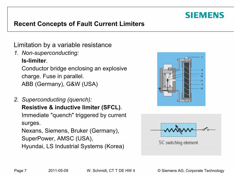
Recent Concepts of Fault Current Limiters
Limitation by a variable resistance1.
Non-superconducting:
Is-limiter. Conductor bridge enclosing an explosive charge. Fuse in parallel.
ABB (Germany), G&W (USA)
2.
Superconducting (quench): Resistive & inductive limiter (SFCL).
Immediate "quench" triggered by current surges.
Nexans, Siemens, Bruker
(Germany), SuperPower, AMSC (USA), Hyundai, LS Industrial Systems (Korea)
Page 8 2011-05-09 © Siemens AG, Corporate TechnologyW. Schmidt, CT T DE HW 4
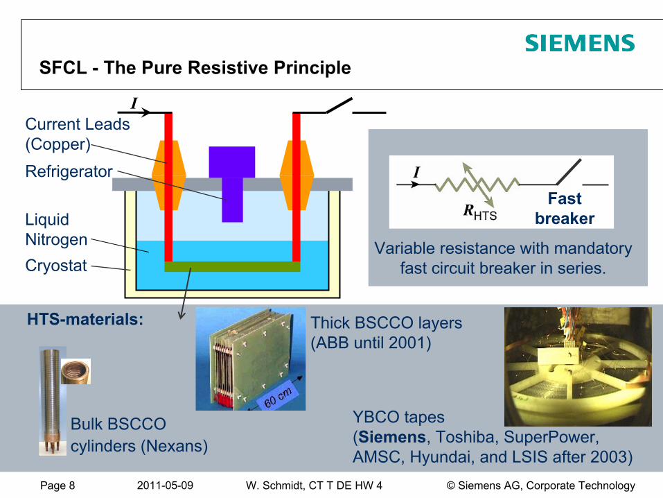
I
Bulk BSCCOcylinders (Nexans)
Thick BSCCO layers (ABB until 2001)
YBCO tapes (Siemens, Toshiba, SuperPower, AMSC, Hyundai, and LSIS after 2003)
Liquid NitrogenCryostat
Current Leads (Copper)
HTS-materials:
Fast breaker
Variable resistance with mandatory fast circuit breaker in series.
Refrigerator
SFCL -
The Pure Resistive Principle
Page 9 2011-05-09 © Siemens AG, Corporate TechnologyW. Schmidt, CT T DE HW 4
0 25 50 75 100 125 150 175
0.00
0.05
0.10
0.15
0.20
0.25
0.30
0.35
0.40
Temperature: 77.5 K 76.1 K 74.9 K 73.1 K 72.2 K 70.5 K 69.2 K
U [m
V]
I [A]
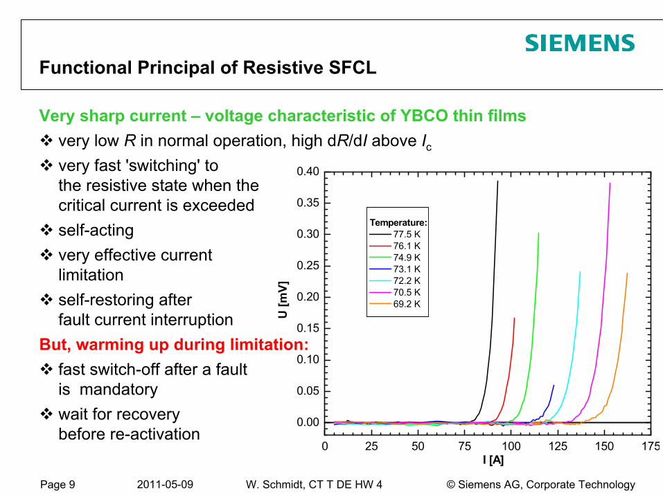
Functional Principal of Resistive SFCL
Very
sharp
current
–
voltage
characteristic
of YBCO thin
filmsvery low R in normal operation, high dR/dI above Icvery fast 'switching' to the resistive state when thecritical current is exceededself-actingvery effective currentlimitationself-restoring afterfault current interruption
But, warming
up during
limitation:fast switch-off after a fault is mandatorywait for recoverybefore re-activation
Page 10 2011-05-09 © Siemens AG, Corporate TechnologyW. Schmidt, CT T DE HW 4
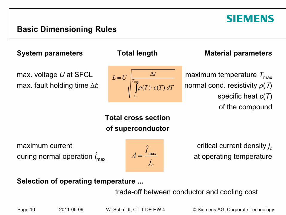
System parameters
Total length
Material parameters
max. voltage
U
at SFCL
maximum
temperature
Tmax
max. fault holding
time Δt:
normal cond. resistivity
ρ(T)specific
heat
c(T)
of the
compoundTotal cross sectionof superconductor
maximum
current
critical
current
density
jc
during
normal operation
Îmax
at operating
temperature
Basic Dimensioning Rules
dTTcT
tUL T
Tc∫ ⋅
Δ=
max
)()(ρ
cjIA maxˆ
=
Selection
of operating
temperature
...trade-off
between
conductor and cooling
cost
Page 11 2011-05-09 © Siemens AG, Corporate TechnologyW. Schmidt, CT T DE HW 4
-
+
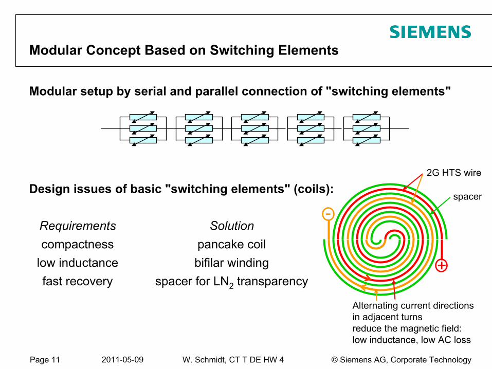
Modular Concept Based on Switching Elements
Design issues
of basic
"switching
elements" (coils):
Requirements
Solutioncompactness
pancake
coil
low
inductance
bifilar
windingfast recovery
spacer
for
LN2
transparency
spacer
2G HTS wire
Alternating
current
directions
in adjacent
turns
reduce
the
magnetic
field:low
inductance, low
AC loss
Modular setup
by
serial
and parallel connection
of "switching
elements"
Page 12 2011-05-09 © Siemens AG, Corporate TechnologyW. Schmidt, CT T DE HW 4
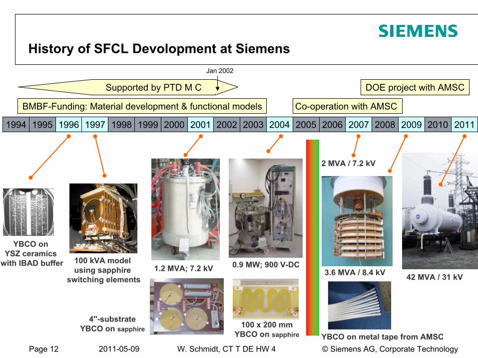
History of SFCL Devolopment
at Siemens
100 kVA
model using sapphire
switching elements1.2 MVA; 7.2 kV
2 MVA / 7.2 kV
0.9 MW; 900 V-DC
YBCO on YSZ ceramics
with IBAD buffer
YBCO on metal tape from AMSC100 x 200 mm
YBCO on sapphire
4''-substrate
YBCO on sapphire
BMBF-Funding: Material development & functional models Co-operation with AMSC
DOE project with AMSC
Jan 2002
Supported by PTD M C
3.6 MVA / 8.4 kV
1994 1995 1996 1997 1998 1999 2000 2001 2002 2003 2004 2005 2006 2007 2008 2009 2010 2011
42 MVA / 31 kV
Page 13 2011-05-09 © Siemens AG, Corporate TechnologyW. Schmidt, CT T DE HW 4
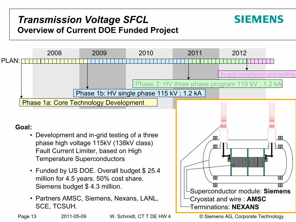
Transmission Voltage SFCL Overview of Current DOE Funded Project
Phase 1a: Core Technology DevelopmentPhase 1b: HV single phase 115 kV ; 1.2 kA
Phase 2: HV three phase program 115 kV ; 1.2 kAIn-grid installation and testing
2008 2009 2010 2011 2012
Goal:•
Development and in-grid testing of a three phase high voltage 115kV (138kV class) Fault Current Limiter, based on High Temperature Superconductors
•
Funded by US DOE. Overall budget $ 25.4 million for 4.5 years. 50% cost share. Siemens budget $ 4.3 million.
•
Partners AMSC, Siemens, Nexans, LANL, SCE, TCSUH.
Superconductor module: SiemensCryostat and wire : AMSCTerminations: NEXANS
PLAN:
Page 14 2011-05-09 © Siemens AG, Corporate TechnologyW. Schmidt, CT T DE HW 4
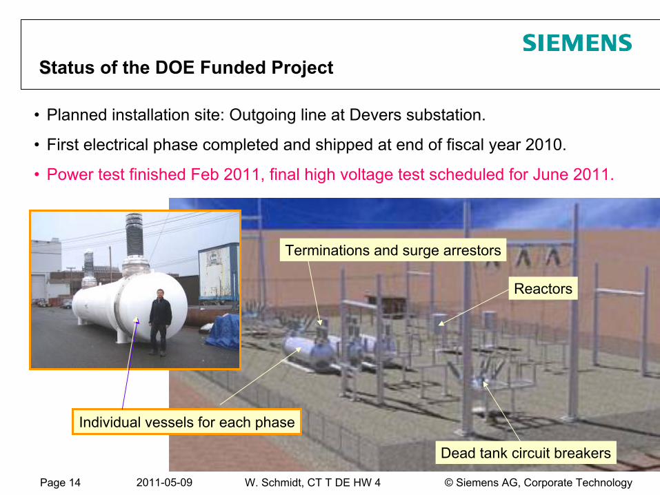
SStatus of the DOE Funded Project
•
Planned installation site: Outgoing line at Devers substation.
•
First electrical phase completed and shipped at end of fiscal year 2010.
•
Power test finished Feb 2011, final high voltage test scheduled for June 2011.
Individual vessels for each phase
Reactors
Terminations and surge arrestors
Dead tank circuit breakers
Page 15 2011-05-09 © Siemens AG, Corporate TechnologyW. Schmidt, CT T DE HW 4
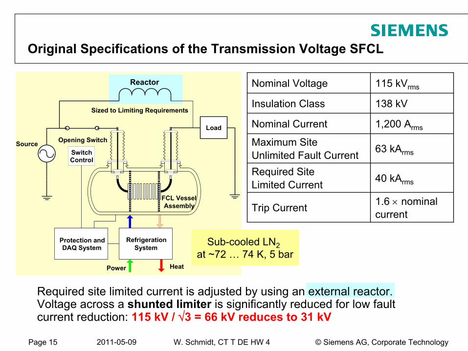
Refrigeration System
Power Heat
FCL Vessel
Protection and DAQ System
Reactor
Sized to Limiting Requirements
Opening SwitchSource
Load
SwitchControl
Assembly
Required site limited current is adjusted by using an external reactor. Voltage across a shunted limiter
is significantly reduced for low fault
current reduction: 115 kV /
√3 = 66 kV reduces to 31
kV
Nominal Voltage 115 kVrms
Insulation Class 138 kV
Nominal Current 1,200 Arms
Maximum Site Unlimited Fault Current 63 kArms
Required Site Limited Current 40 kArms
Trip Current 1.6 ×
nominal current
Original Specifications of the Transmission Voltage SFCL
Sub-cooled
LN2
at ~72 …
74 K, 5 bar
Page 16 2011-05-09 © Siemens AG, Corporate TechnologyW. Schmidt, CT T DE HW 4
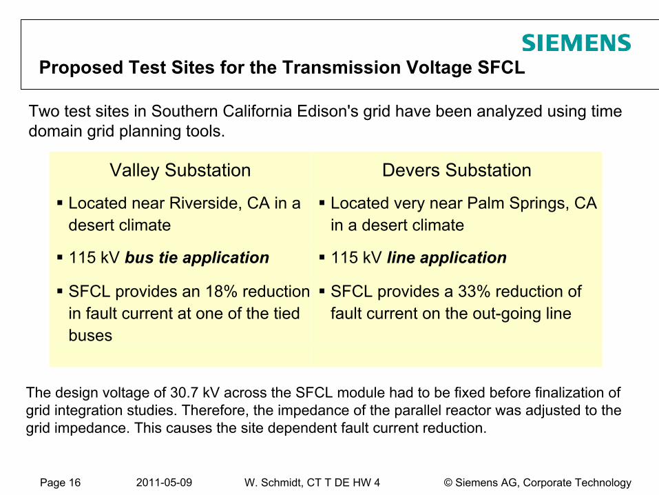
Proposed Test Sites for the Transmission Voltage SFCL
Two test sites in Southern California Edison's grid have been analyzed using time domain grid planning tools.
Valley Substation Devers Substation
Located near Riverside, CA in a desert climate
Located very near Palm Springs, CA in a desert climate
115 kV bus tie application 115 kV line application
SFCL provides an 18% reduction in fault current at one of the tied buses
SFCL provides a 33% reduction of fault current on the out-going line
The design voltage of 30.7 kV across the SFCL module had to be fixed before finalization of grid integration studies. Therefore, the impedance of the parallel reactor was adjusted to the grid impedance. This causes the site dependent fault current reduction.
Page 17 2011-05-09 © Siemens AG, Corporate TechnologyW. Schmidt, CT T DE HW 4
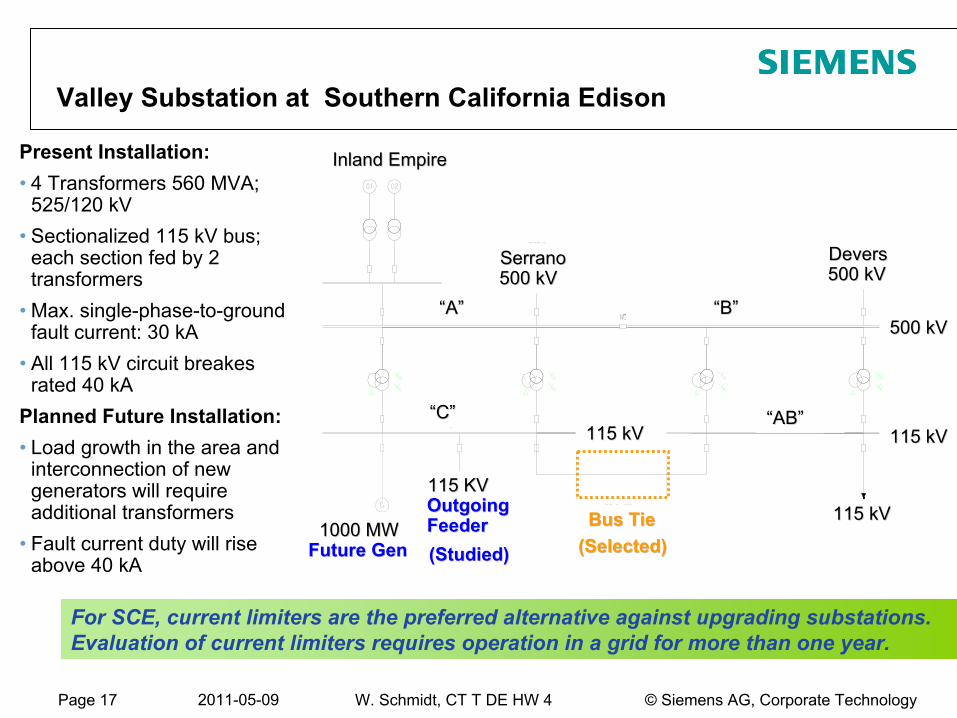
Valley Substation at Southern California Edison
Bus TieBus Tie
115 KV 115 KV Outgoing Outgoing FeederFeeder1000 MW 1000 MW
Future GenFuture Gen
Inland EmpireInland Empire
115 kV115 kV
115 kV115 kV
500 kV500 kV
115 kV115 kV
““AA”” ““BB””
““CC”” ““ABAB””
SerranoSerrano
500 kV500 kV
Devers Devers 500 kV500 kV
(Studied)(Studied) (Selected)(Selected)
Present Installation:•
4 Transformers 560 MVA; 525/120 kV
•
Sectionalized 115 kV bus;
each section fed by 2 transformers
•
Max. single-phase-to-ground fault current: 30 kA
•
All 115 kV circuit breakes
rated 40 kA
Planned Future Installation:•
Load growth in the area and interconnection of new generators will require additional transformers
•
Fault current duty will rise above 40 kA
For SCE, current
limiters
are
the
preferred
alternative against
upgrading
substations.Evaluation of current
limiters
requires
operation
in a grid
for
more
than
one
year.
Page 18 2011-05-09 © Siemens AG, Corporate TechnologyW. Schmidt, CT T DE HW 4
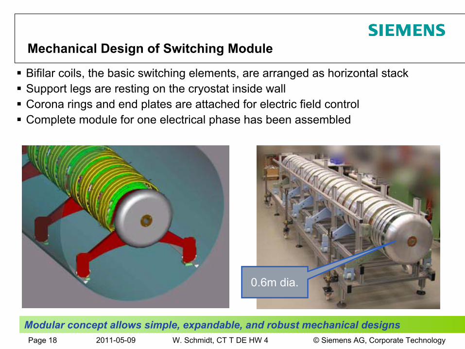
Bifilar coils, the basic switching elements, are arranged as horizontal stack Support legs are resting on the cryostat inside wallCorona rings and end plates are attached for electric field controlComplete module for one electrical phase has been assembled
Modular concept allows simple, expandable, and robust mechanical
designs
Mechanical Design of Switching Module
0.6m dia.
Page 19 2011-05-09 © Siemens AG, Corporate TechnologyW. Schmidt, CT T DE HW 4
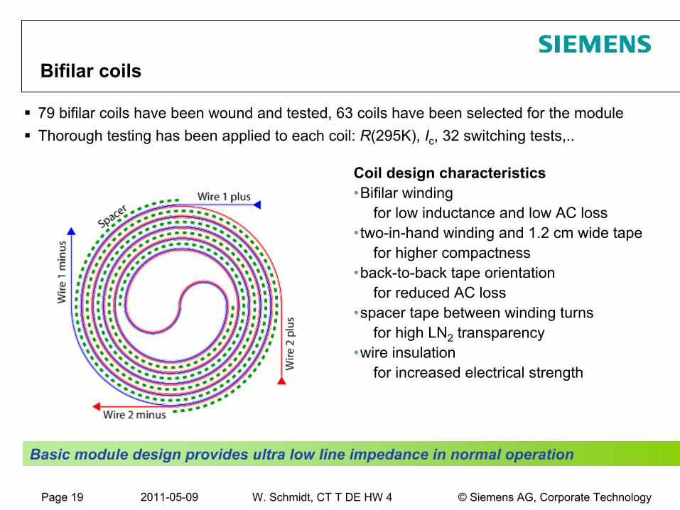
79 bifilar coils have been wound and tested, 63 coils have been selected for the moduleThorough testing has been applied to each coil: R(295K), Ic, 32 switching tests,..
Coil design characteristics•Bifilar winding
for low inductance and low AC loss•two-in-hand winding and 1.2 cm wide tape
for higher compactness•back-to-back tape orientation
for reduced AC loss•spacer tape between winding turns
for high LN2
transparency•wire insulation
for increased electrical strength
Basic module design provides ultra low line impedance in normal operation
Bifilar coils
Page 20 2011-05-09 © Siemens AG, Corporate TechnologyW. Schmidt, CT T DE HW 4
-4
-2
0
2
4
-10 0 10 20 30 40 50 60 700
20406080
100120
-4
-2
0
2
4
Current ICur
rent
(kA
)
time (ms)
Res
ista
nce
ratio
(%)
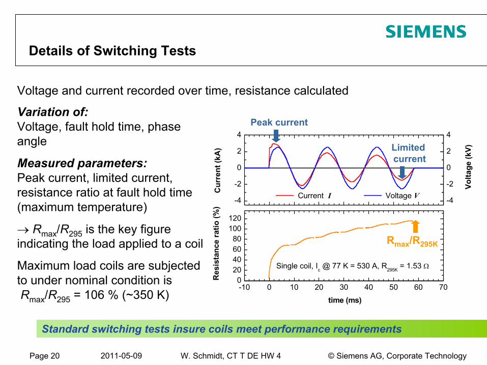
Single coil, Ic @ 77 K = 530 A, R295K = 1.53 Ω
Voltage V
Vol
tage
(kV)
Voltage and current recorded over time, resistance calculated
Variation of: Voltage, fault hold time, phase
angle
Measured parameters: Peak current, limited current,
resistance ratio at fault hold time (maximum temperature)
→ Rmax
/R295
is the key figure indicating the load applied to a coil
Maximum load coils are subjected to under nominal condition is Rmax
/R295
= 106 % (~350 K)
Rmax
/R295K
Peak current
Limited
current
Standard switching
tests insure
coils
meet
performance requirements
Details of Switching Tests
Page 21 2011-05-09 © Siemens AG, Corporate TechnologyW. Schmidt, CT T DE HW 4
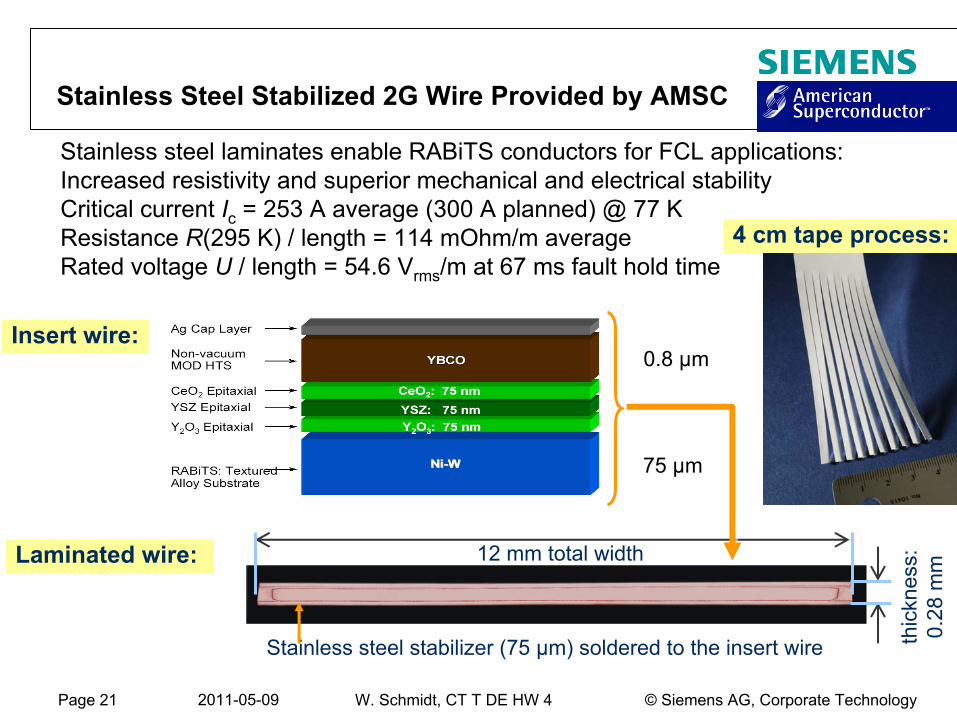
Stainless Steel Stabilized 2G Wire Provided by AMSC
Insert wire:
Laminated wire: 12 mm total width
thic
knes
s:0.
28 m
m
Stainless steel stabilizer (75 µm) soldered to the insert wire
Stainless steel laminates enable RABiTS
conductors for FCL applications: Increased resistivity and superior mechanical and electrical stability Critical current Ic
= 253 A average (300 A planned) @ 77 KResistance R(295 K) / length = 114 mOhm/m
average
Rated voltage U
/ length = 54.6 Vrms
/m
at 67 ms fault hold time
75 µm
0.8 µm
4 cm tape process:
Page 22 2011-05-09 © Siemens AG, Corporate TechnologyW. Schmidt, CT T DE HW 4
Page 23 2011-05-09 © Siemens AG, Corporate TechnologyW. Schmidt, CT T DE HW 4
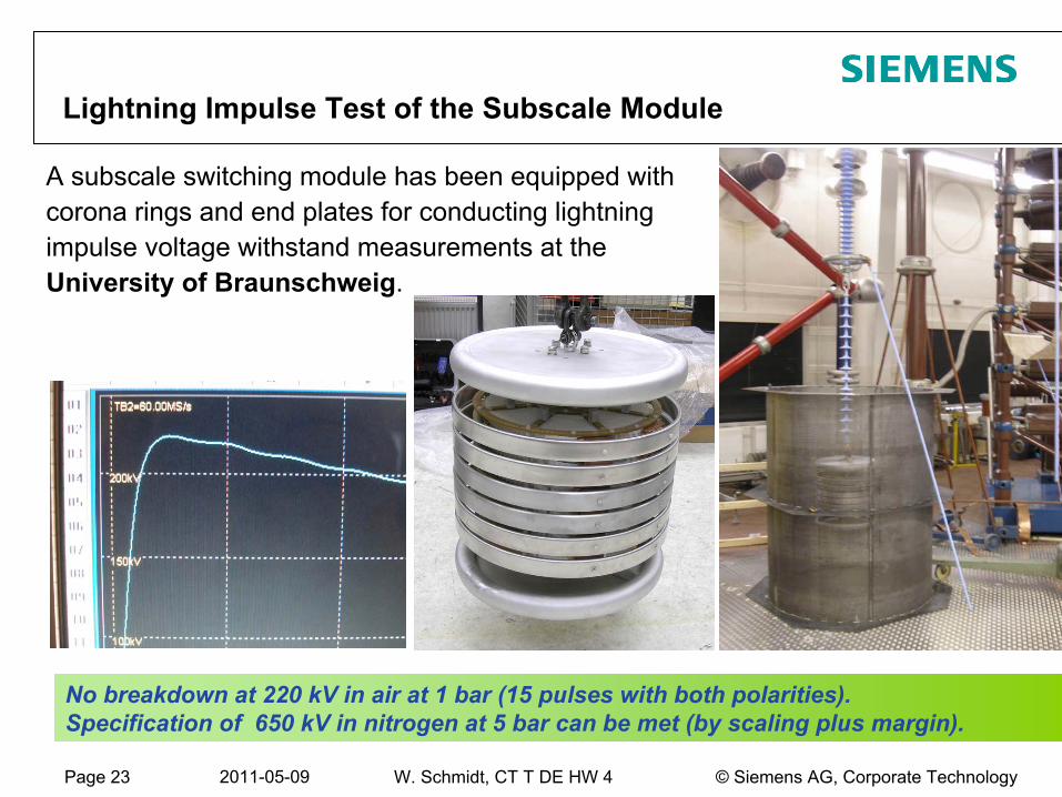
Lightning Impulse Test of the Subscale Module
A subscale switching module has been equipped with corona rings and end plates for conducting lightning impulse voltage withstand measurements at the University of Braunschweig.
No breakdown at 220 kV in air at 1 bar (15 pulses with both polarities).Specification of 650 kV in nitrogen at 5 bar can be met (by scaling plus margin).
Page 24 2011-05-09 © Siemens AG, Corporate TechnologyW. Schmidt, CT T DE HW 4
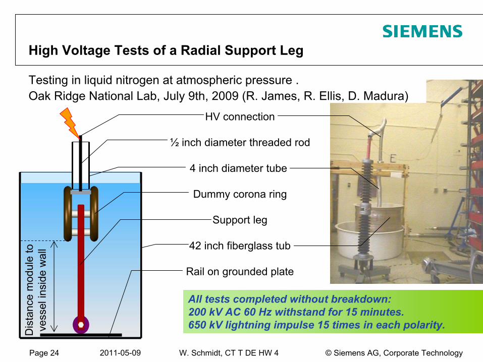
All tests completed without breakdown:200 kV AC 60 Hz withstand for 15 minutes.650 kV lightning impulse 15 times in each polarity.
HV connection
½
inch diameter threaded rod
4 inch diameter tube
Dummy corona ring
Support leg
42 inch fiberglass tub
Rail on grounded plate
High Voltage Tests of a Radial Support Leg
Testing in liquid nitrogen at atmospheric pressure . Oak Ridge National Lab, July 9th, 2009 (R. James, R. Ellis, D. Madura)
Dis
tanc
e m
odul
eto
ve
ssel
insi
dew
all
Page 25 2011-05-09 © Siemens AG, Corporate TechnologyW. Schmidt, CT T DE HW 4
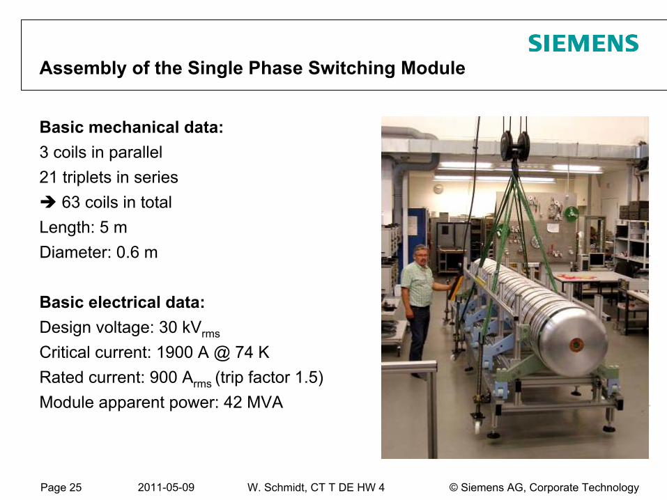
Basic mechanical data:3 coils in parallel21 triplets in series
63 coils in totalLength: 5 mDiameter: 0.6 m
Basic electrical data:Design voltage: 30 kVrms
Critical current: 1900 A @ 74 KRated current: 900 Arms (trip factor 1.5)Module apparent power: 42 MVA
∅
535
350
Assembly of the Single Phase Switching Module
Page 26 2011-05-09 © Siemens AG, Corporate TechnologyW. Schmidt, CT T DE HW 4
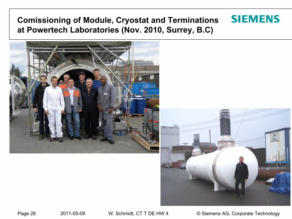
Comissioning
of Module, Cryostat and Terminations at Powertech
Laboratories (Nov. 2010, Surrey, B.C)
Page 27 2011-05-09 © Siemens AG, Corporate TechnologyW. Schmidt, CT T DE HW 4
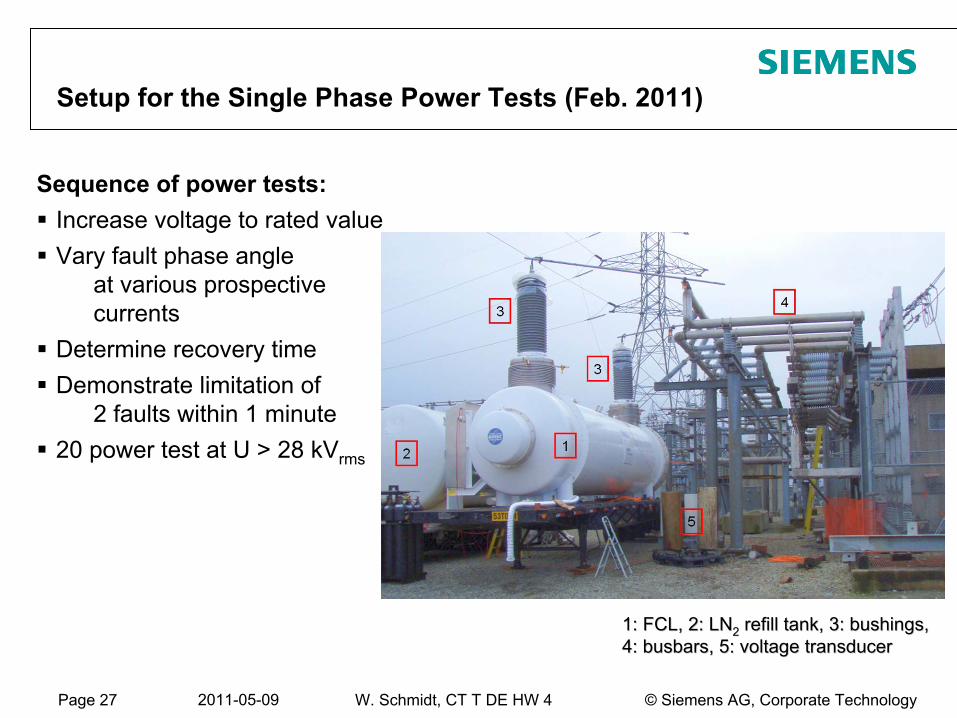
Setup for the Single Phase Power Tests (Feb. 2011)
1: FCL, 2: LN1: FCL, 2: LN
22
refillrefill
tank, 3: tank, 3: bushingsbushings, , 4: 4: busbarsbusbars, 5: , 5: voltagevoltage
transducertransducer
Sequence of power tests:Increase voltage to rated valueVary fault phase angle
at various prospective currents
Determine recovery timeDemonstrate limitation of
2 faults within 1 minute20 power test at U > 28 kVrms
Page 28 2011-05-09 © Siemens AG, Corporate TechnologyW. Schmidt, CT T DE HW 4
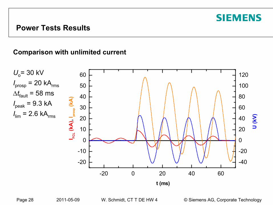
Comparison with unlimited current
Uo
= 30 kVIprosp
= 20 kArms
Δtfault
= 58 msIpeak
= 9.3 kAIlim
= 2.6 kArms
Power Tests Results
-20 0 20 40 60
-20
-10
0
10
20
30
40
50
60
-40
-20
0
20
40
60
80
100
120
t (ms)
I FCL (
kA),
I pros
p (kA
)
U (k
V)
Page 29 2011-05-09 © Siemens AG, Corporate TechnologyW. Schmidt, CT T DE HW 4
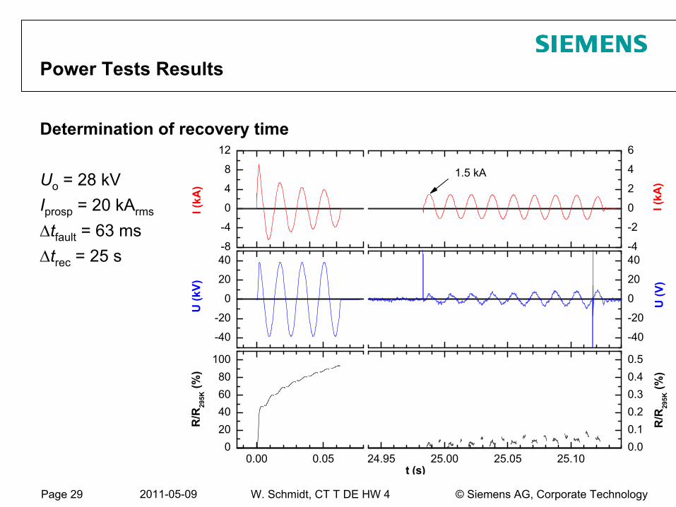
Determination of recovery time
Uo
= 28 kVIprosp
= 20 kArms
Δtfault
= 63 msΔtrec
= 25 s
Power Tests Results
-8
-4
0
4
8
12
-4
-2
0
2
4
6
-40
-20
0
20
40
-40
-20
0
20
40
0.00 0.050
20406080
100
24.95 25.00 25.05 25.100.00.10.20.30.40.5
I (k
A)
I (k
A)
1.5 kA
U (k
V)
U (V
)
R/R
295K
(%)
t (s)
R/R
295K
(%)
Page 30 2011-05-09 © Siemens AG, Corporate TechnologyW. Schmidt, CT T DE HW 4
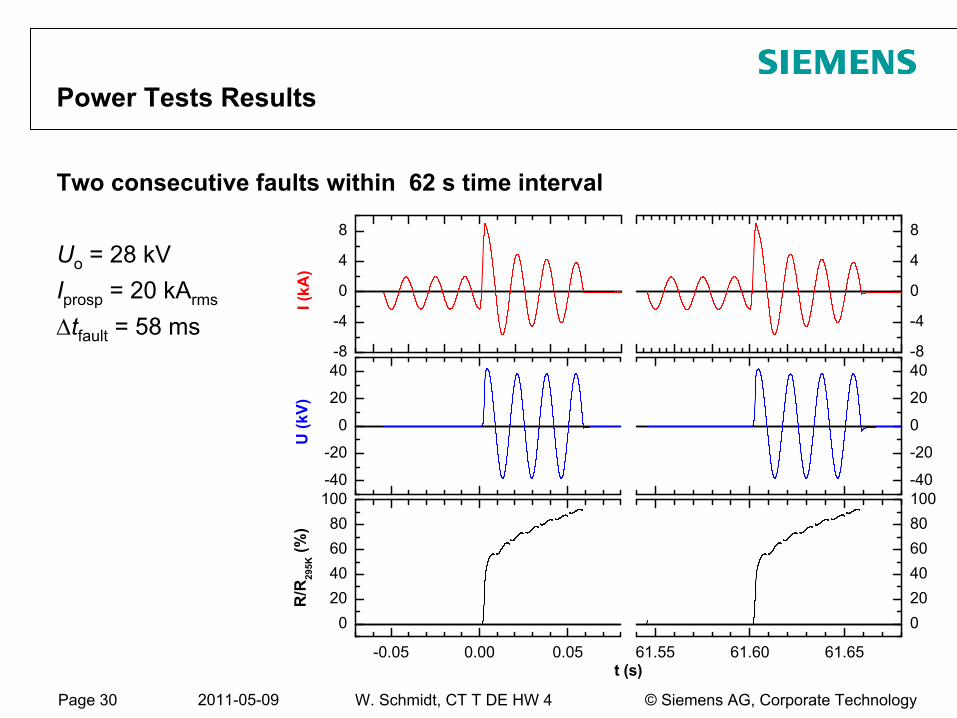
Two consecutive faults within 62 s time interval
Uo
= 28 kVIprosp
= 20 kArms
Δtfault
= 58 ms
Power Tests Results
-8
-4
0
4
8
-8
-4
0
4
8
-40
-20
0
20
40
-40
-20
0
20
40
-0.05 0.00 0.05
020406080
100
61.55 61.60 61.65
020406080100
I (k
A)
U (k
V)
R/R
295K
(%)
t (s)
Page 31 2011-05-09 © Siemens AG, Corporate TechnologyW. Schmidt, CT T DE HW 4
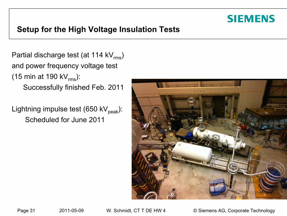
Setup for the High Voltage Insulation Tests
Partial discharge test (at 114 kVrms
) and power frequency voltage test (15 min at 190 kVrms
):Successfully finished Feb. 2011
Lightning impulse test (650 kVpeak
):Scheduled for June 2011
Page 32 2011-05-09 © Siemens AG, Corporate TechnologyW. Schmidt, CT T DE HW 4
Conclusion and Outlook
Project phase 1a successfully finishedDesign of bifilar coils as switching elements under HV aspectsSubscale module made of 6 full size coils fabricated
and successfully tested at IPH Berlin, 8.4 kV ×
425 A = 3.5 MVA
Project phase 1b mostly finished:One complete phase of the FCL manufacturedRated apparent power: 30.9 kV ×
1.35 kA = 42 MVA (74 K)
Power tests at PowerTech
labs. (Surrrey) passed successfullyHigh voltage tests to be repeated in June 2011
Phase 2 canceled by DOE due to shift in funding