Einleitungsseiten 2016 EN Einleitungsseiten - isel Prag · 2019-12-16 · SYSTEMS Robotic Robotic...
14
SYSTEMS Robotic E-45 Robotic systems Overview Wafer Handling Robots IWH Series 1 with 2-link compact arm and 7 inch body series 1 E-46 Wafer Handling Robots IWH Series 1 with 2-Link-Heavy-Duty arm and standard body E-47 Wafer Handling Robots IWH Series 1 with 3-Link-Heavy-Duty arm and standard body E-48 Wafer Handling Robots IWH Series 3 with 2-Link dual arm and body series 3 E-50 Wafer Handling Robots IWH Series 3 with 2-Link HDplus arm and body series 3 E-49 Wafer Handling Robots IWH Series SHD with SHD dual arm and series SHD body E-51 Controller & Software „Standard“ E-52 Controller & Software „Advanced“ E-53 Linear Track E-54 End effectors E-55 Prealigner E-56 Accessories E-58 References E-59 Series 1 robots are designed for wafer handling. The modular system allows the combination of various base bodies, from 7" to 21" Z stroke, with a large number of different arm modules from 10.5" to 28". Handling weights of up to 3 kg are also possible with the appropriate combination of axes. Series 3 single-arm robots are used wherever a higher structural rigidity is required. They can be used with loads of up to 3 kg, even in combination with long arm modules and a large Z stroke of up to 21". Series 3 dual-arm robots have the potential to increase the throughput of an application. The two independent arms mean that the wafers on a station can be replaced very quickly and thus empty runs are prevented.
Transcript of Einleitungsseiten 2016 EN Einleitungsseiten - isel Prag · 2019-12-16 · SYSTEMS Robotic Robotic...
SYSTEMS
Robotic
E-45Robotic
systems
Overview
Wafer Handling Robots IWH Series 1with 2-link compact arm and 7 inch body series 1
E-46
Wafer Handling Robots IWH Series 1with 2-Link-Heavy-Duty arm and standard body
E-47
Wafer Handling Robots IWH Series 1with 3-Link-Heavy-Duty arm and standard body
E-48
Wafer Handling Robots IWH Series 3with 2-Link dual arm and body series 3
E-50
Wafer Handling Robots IWH Series 3with 2-Link HDplus arm and body series 3
E-49
Wafer Handling Robots IWH Series SHDwith SHD dual arm and series SHD body
E-51
Controller & Software „Standard“ E-52
Controller & Software „Advanced“ E-53
Linear Track E-54
End effectors E-55
Prealigner E-56
Accessories E-58
References E-59
Series 1 robots are designed for wafer handling. The modular system allows the combination of various base bodies, from 7" to 21" Zstroke, with a large number of different arm modules from 10.5" to 28". Handling weights of up to 3 kg are also possible with theappropriate combination of axes.
Series 3 single-arm robots are used wherever a higher structural rigidity is required. They can be used with loads of up to 3 kg, evenin combination with long arm modules and a large Z stroke of up to 21".
Series 3 dual-arm robots have the potential to increase the throughput of an application. The two independent arms mean that thewafers on a station can be replaced very quickly and thus empty runs are prevented.
SYSTEMS
Robotic
E-46 Robotic
syst
ems
Dimensioned drawings
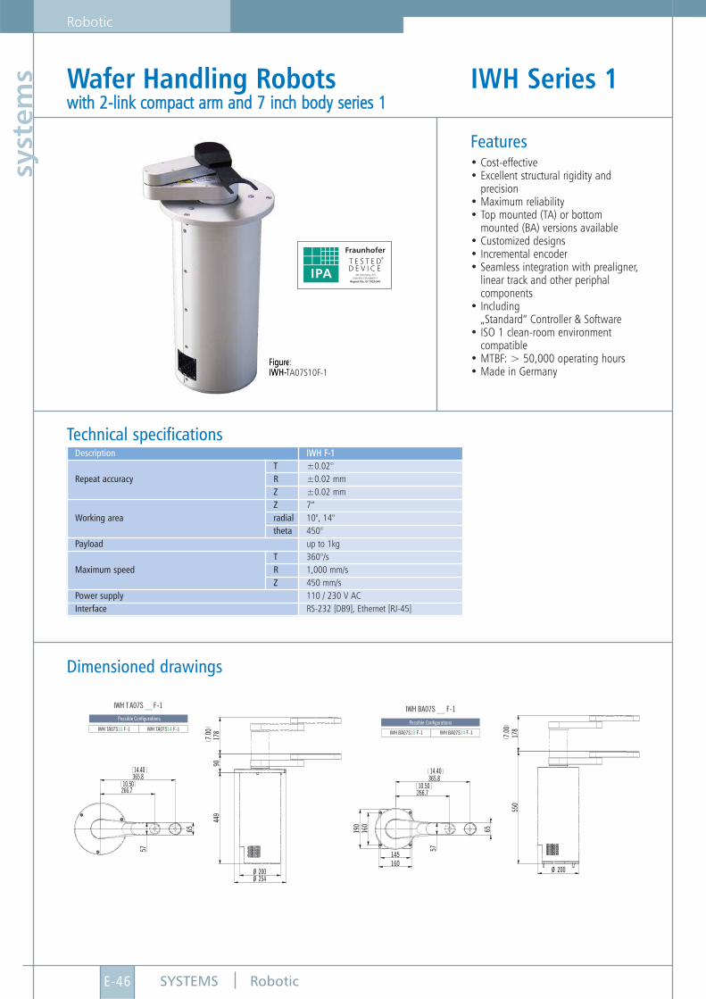
Features• Cost-effective• Excellent structural rigidity and
precision• Maximum reliability• Top mounted (TA) or bottom
mounted (BA) versions available• Customized designs• Incremental encoder• Seamless integration with prealigner,
linear track and other periphal components
• Including „Standard“ Controller & Software
• ISO 1 clean-room environment compatible
• MTBF: > 50,000 operating hours• Made in Germany
Technical specifications
Wafer Handling Robots IWH Series 1wwiitthh 22--lliinnkk ccoommppaacctt aarrmm aanndd 77 iinncchh bbooddyy sseerriieess 11
Figure:IWH-TA07S10F-1
IWH TA07S F-1 IWH BA07S F-1__ __
IWH TA S F-1IWH BA07S10 F-1 IWH BA07S14 F-1
07 10 IWH TA S F-107 14
Possible ConfigurationsPossible Configurations
7.00
178
449
90
Ø 200Ø 254
10.50266.7
14.40365.8
65
57
7.00
178
Ø 200
550
160
190
145160
65
10.50266.7
14.40365.8
57
Description IIWWHH FF--11
Repeat accuracyT ±0.02°R ±0.02 mmZ ±0.02 mm
Working areaZ 7“radial 10", 14"theta 450°
Payload up to 1kg
Maximum speed T 360°/sR 1,000 mm/sZ 450 mm/s
Power supply 110 / 230 V ACInterface RS-232 [DB9], Ethernet [RJ-45]
SYSTEMS
Robotic
E-47Robotic
systems
Dimensioned drawings
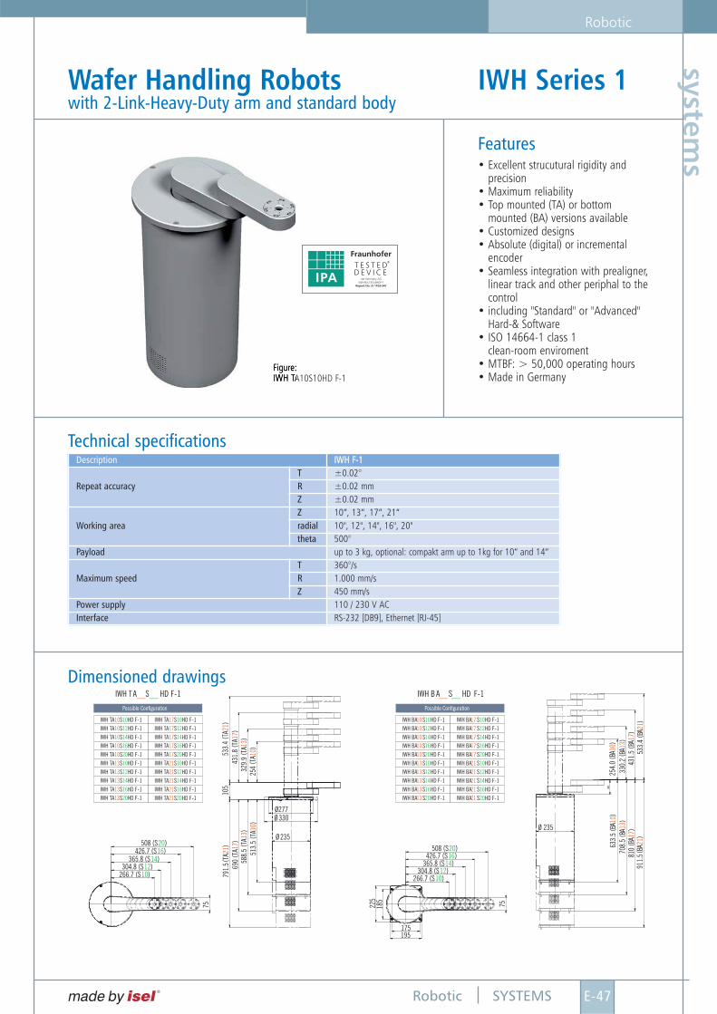
Wafer Handling Robots IWH Series 1with 2-Link-Heavy-Duty arm and standard body
Figure:IWH TA10S10HD F-1
Features• Excellent strucutural rigidity and
precision• Maximum reliability• Top mounted (TA) or bottom
mounted (BA) versions available• Customized designs• Absolute (digital) or incremental
encoder• Seamless integration with prealigner,
linear track and other periphal to thecontrol
• including "Standard" or "Advanced" Hard-& Software
• ISO 14664-1 class 1clean-room enviroment
• MTBF: > 50,000 operating hours• Made in Germany
Technical specifications
IWH TA S F-1 IWH B A S F-1__ ____ __HD HD
IWH TA S HD F-1 IWH BA S HD F-110 1010 10IWH TA S HD F-1 IWH BA S HD F-110 1012 12IWH TA S HD F-1 IWH BA S HD F-110 1014 14IWH TA S HD F-1 IWH BA S HD F-110 1016 16IWH TA S HD F-1 IWH BA S HD F-110 1020 20IWH TA S HD F-1 IWH BA S HD F-113 1310 10IWH TA S HD F-1 IWH BA S HD F-1
IWH TA S HD F-1 IWH BA S HD F-1
13 13
13 13
12 12
16 16IWH TA S HD F-1 IWH BA S HD F-1
IWH TA S HD F-1 IWH BA S HD F-1
13 13
13 13
14 14
20 20
IWH TA S HD F-1 IWH BA S HD F-117 1710 10IWH TA S HD F-1 IWH BA S HD F-117 1712 12IWH TA S HD F-1 IWH BA S HD F-117 1714 14IWH TA S HD F-1 IWH BA S HD F-117 1716 16IWH TA S HD F-1 IWH BA S HD F-117 1720 20IWH TA S HD F-1 IWH BA S HD F-121 2110 10IWH TA S HD F-1 IWH BA S HD F-1
IWH TA S HD F-1 IWH BA S HD F-1IWH TA S HD F-1 IWH BA S HD F-1
IWH TA S HD F-1 IWH BA S HD F-1
21 21
21 2121 21
21 21
12 12
16 1614 14
20 20
Possible Configuration Possible Configuration
513.
5(T
A)
105 8
8 .5
( TA
)1 3
6 90
7 91 .
5( T
A)
( TA
) 1 72 14 3
1 .85 3
3 .4 ( TA
)( T
A)
1 72 1
3 29 .
9( T
A)
1 32 5
4( T
A)
1 0
508 (S )20Ø 235
Ø277Ø 330
266.7 (S )10304.8 (S )12
365.8 (S )14426.7 (S )16
75
105
633.
5(B
A)
1 07 0
8 .5
( BA
)1 3
8 10
9 11 .
5( B
A)
( BA
)1 72 1
3 30 .
22 5
4 .0
( BA
)( B
A) 1 31 0
4 31 .
5 5 33 .
4( B
A) ( BA
)1 7
2 1
Ø 235
266.7 (S )10304.8 (S )12
365.8 (S )14426.7 (S )16
508 (S )20
185 75225
175195
90
Description IIWWHH FF--11
Repeat accuracyT ±0.02°R ±0.02 mmZ ±0.02 mm
Working areaZ 10”, 13”, 17”, 21“radial 10", 12", 14", 16", 20"theta 500°
Payload up to 3 kg, optional: compakt arm up to 1kg for 10“ and 14“
Maximum speedT 360°/sR 1.000 mm/sZ 450 mm/s
Power supply 110 / 230 V ACInterface RS-232 [DB9], Ethernet [RJ-45]
SYSTEMS
Robotic
E-48 Robotic
syst
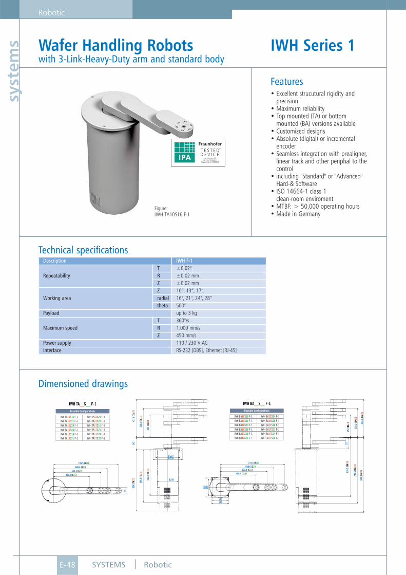
ems Wafer Handling Robots IWH Series 1
with 3-Link-Heavy-Duty arm and standard body
Features• Excellent strucutural rigidity and
precision• Maximum reliability• Top mounted (TA) or bottom
mounted (BA) versions available• Customized designs• Absolute (digital) or incremental
encoder• Seamless integration with prealigner,
linear track and other periphal to thecontrol
• including "Standard" or "Advanced" Hard-& Software
• ISO 14664-1 class 1clean-room enviroment
• MTBF: > 50,000 operating hours• Made in Germany
Technical specificationsDescription IIWWHH FF--11
RepeatabilityT ±0.02°R ±0.02 mmZ ±0.02 mm
Working areaZ 10”, 13”, 17”, radial 16", 21", 24", 28“theta 500°
Payload up to 3 kg
Maximum speedT 360°/sR 1.000 mm/sZ 450 mm/s
Power supply 110 / 230 V ACInterface RS-232 [DB9], Ethernet [RJ-45]
Dimensioned drawings
Figure:IWH TA10S16 F-1
SYSTEMS
Robotic
E-49Robotic
systems
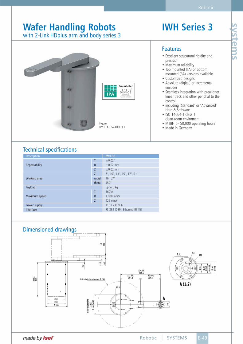
Features• Excellent strucutural rigidity and
precision• Maximum reliability• Top mounted (TA) or bottom
mounted (BA) versions available• Customized designs• Absolute (digital) or incremental
encoder• Seamless integration with prealigner,
linear track and other periphal to thecontrol
• including "Standard" or "Advanced" Hard-& Software
• ISO 14664-1 class 1clean-room enviroment
• MTBF: > 50,000 operating hours• Made in Germany
Wafer Handling Robots IWH Series 3 with 2-Link HDplus arm and body series 3
Technical specifications
A
A (1:2)
20.6
7
1.39
2.00
5 25
Ø 35 .
3
Ø 50 .
82 5
8 3. 5
82.5
24.00
12.00 12.00609.6
Ø 3
Ø20
400.
01±
M3M4
304.8 304.8
Mou
ntin
g sc
rew s
1 1. 8
1Ø
3 00
3 x M
6
3 9. 5
9 0
3 30
1 3
264
district circle minimum Ø 700
284Ø 330
Description IIWWHH FF--33
RepeatabilityT ±0.02°R ±0.02 mmZ ±0.02 mm
Working areaZ 7“, 10”, 13”, 15“, 17”, 21“radial 16", 24"theta 450°
Payload up to 5 kg
Maximum speedT 360°/sR 1.000 mm/sZ 425 mm/s
Power supply 110 / 230 V ACInterface RS-232 [DB9], Ethernet [RJ-45]
Dimensioned drawings
Figure:IWH TA13S24HDP F3
SYSTEMS
Robotic
E-50 Robotic
syst
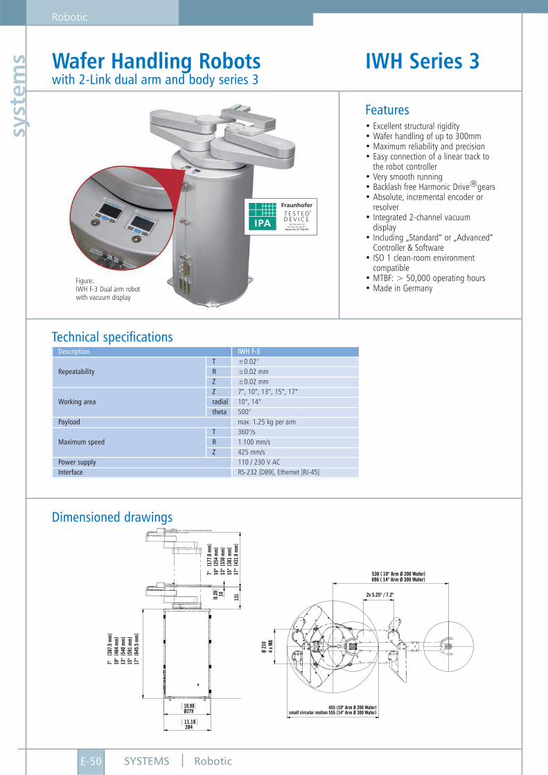
ems Wafer Handling Robots IWH Series 3
with 2-Link dual arm and body series 3
Features• Excellent structural rigidity• Wafer handling of up to 300mm• Maximum reliability and precision• Easy connection of a linear track to
the robot controller• Very smooth running• Backlash free Harmonic Drive®gears• Absolute, incremental encoder or
resolver• Integrated 2-channel vacuum
display• Including „Standard“ or „Advanced“
Controller & Software• ISO 1 clean-room environment
compatible• MTBF: > 50,000 operating hours• Made in Germany
Technical specificationsDescription IIWWHH FF--33
RepeatabilityT ±0.02°R ±0.02 mmZ ±0.02 mm
Working areaZ 7“, 10“, 13“, 15“, 17“radial 10“, 14“theta 500°
Payload max. 1.25 kg per arm
Maximum speedT 360°/sR 1.100 mm/sZ 425 mm/s
Power supply 110 / 230 V ACInterface RS-232 [DB9], Ethernet [RJ-45]
Figure:IWH F-3 Dual arm robotwith vacuum display
7 "
[ 38 7
. 5 m
m]
1 0"
[ 46 4
mm
]1 3
" [ 5
4 0 m
m]
1 5"
[ 59 1
mm
]1 7
" [ 6
4 5. 5
mm
]
7 "
[ 17 7
. 8 m
m]
1 0"
[ 25 4
mm
]1 3
" [ 3
3 0 m
m]
1 5"
[ 38 1
mm
]1 7
" [ 4
3 1. 8
mm
]1 3
10 .3 9 1 0
11.18284
10.98Ø279
530 ( 10" Arm Ø 200 Wafer)696 ( 14" Arm Ø 300 Wafer)
2x 5.25" / 7.2"
small circular motion
Ø 21
04
x M8
455 (10" Arm Ø 200 Wafer)555 (14" Arm Ø 300 Wafer)
Dimensioned drawings
SYSTEMS
Robotic
E-51Robotic
systems
made by isel ®
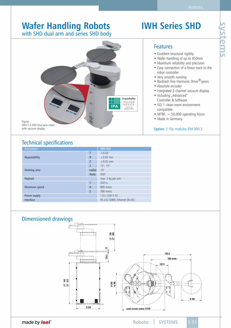
Features• Excellent structural rigidity• Wafer handling of up to 450mm• Maximum reliability and precision• Easy connection of a linear track to the
robot controller• Very smooth running• Backlash free Harmonic Drive®gears• Absolute encoder• Integrated 2-channel vacuum display• Including „Advanced“
Controller & Software• ISO 1 clean-room environment
compatible• MTBF: > 50,000 operating hours• Made in Germany
Option: 2 Flip modules iFM-300-3
Wafer Handling Robots IWH Series SHD with SHD dual arm and series SHD body
Technical specificationsDescription IIWWHH SSHHDD
RepeatabilityT ±0.02°R ±0.02 mmZ ±0.02 mm
Working areaZ 13“, 15“radial 14“theta 450°
Payload max. 3 kg per arm
Maximum speedT 250°/sR 800 mm/sZ 300 mm/s
Power supply 110 / 230 V ACInterface RS-232 [DB9], Ethernet [RJ-45]
Figure:IWH F-3 SHD Dua larm robotwith vacuum display
Ø 300
Ø 630
705.8
598
182.9
stroke
small circular motion
Ø 26
04x
M8
13"
54 2
1 5"
61 2
Ø 350
156,
510
13"
33 0
1 5"
40 0
Dimensioned drawings
SYSTEMS
Robotic
E-52 Robotic
syst
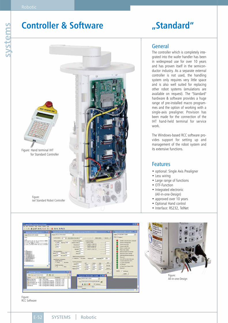
ems Controller & Software „Standard“
GeneralThe controller which is completely inte-grated into the wafer handler has beenin widespread use for over 10 yearsand has proven itself in the semicon-ductor industry. As a separate externalcontroller is not used, the handlingsystem only requires very little spaceand is also well suited for replacingother robot systems (emulations areavailable on request). The "Standard"hardware & software provides a hugerange of pre-installed macro program-mes and the option of working with asingle-axis prealigner. Provision hasbeen made for the connection of theIHT hand-held terminal for servicework.
The Windows-based RCC software pro-vides support for setting up andmanagement of the robot system andits extensive functions.
Features• optional: Single Axis Prealigner• Less wiring• Large range of functions• OTF-Function• Integrated electronic
(All-in-one-Design)• approved over 10 years• Optional Hand control• Interface: RS232, TelNet
Figure:isel Standard Robot Controller
Figure:All-in-one-Design
Figure:RCC Software
Figure: Hand terminal IHTfor Standard Controller
SYSTEMS
Robotic
E-53Robotic
systems
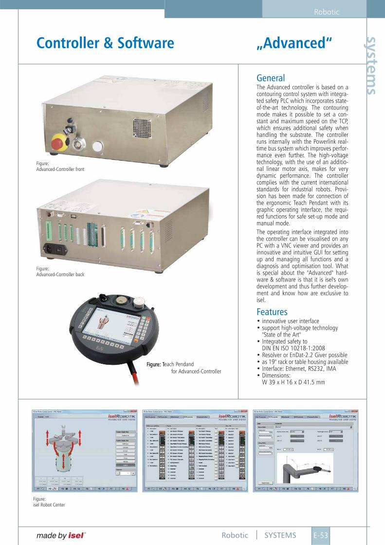
Controller & Software „Advanced“
Figure:isel Robot Center
Figure:Advanced-Controller front
Figure:Advanced-Controller back
GeneralThe Advanced controller is based on acontouring control system with integra-ted safety PLC which incorporates state-of-the-art technology. The contouringmode makes it possible to set a con-stant and maximum speed on the TCP,which ensures additional safety whenhandling the substrate. The controllerruns internally with the Powerlink real-time bus system which improves perfor-mance even further. The high-voltagetechnology, with the use of an additio-nal linear motor axis, makes for verydynamic performance. The controllercomplies with the current internationalstandards for industrial robots. Provi-sion has been made for connection ofthe ergonomic Teach Pendant with itsgraphic operating interface, the requi-red functions for safe set-up mode andmanual mode.The operating interface integrated intothe controller can be visualised on anyPC with a VNC viewer and provides aninnovative and intuitive GUI for settingup and managing all functions and adiagnosis and optimisation tool. Whatis special about the "Advanced" hard-ware & software is that it is isel's owndevelopment and thus further develop-ment and know how are exclusive toisel.
Features• innovative user interface• support high-voltage technology
"State of the Art"• Integrated safety to
DIN EN ISO 10218-1:2008• Resolver or EnDat-2.2 Giver possible• as 19" rack or table housing available• Interface: Ethernet, RS232, IMA • Dimensions:
W 39 x H 16 x D 41.5 mm
Figure: Teach Pendandfor Advanced-Controller
SYSTEMS
Robotic
E-54 Robotic
syst
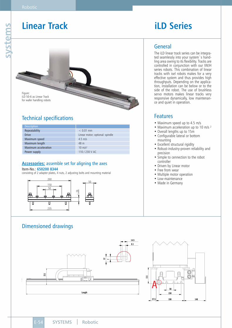
ems Linear Track iLD Series
Figure:iLD 50-6 as Linear Trackfor wafer handling robots
Item-No.: 650200 8344consisting of 2 adapter plates, 4 nuts, 2 adjusting bolts and mounting material
GeneralThe iLD linear track series can be integra-ted seamlessly into your system`s hand-ling area owing to its flexibility. Tracks arecontrolled in conjunction with our IWJHseries robots. This combination of lineartracks with isel robots makes for a veryeffective system and thus provides highthroughputs. Depending on the applica-tion, installation can be below or to theside of the robot. The use of brushlessservo motors makes linear tracks veryresponsive dynamically, low maintenan-ce and quiet in operation.
Features• Maximum speed up to 4.5 m/s• Maximum accekeration up to 10 m/s ²• Overall lengths up to 15m• Configurable lateral or bottom
mounting• Excellent structural rigidity• Robust-industry-proven reliability and
precision• Simple to cennection to the robot
controller• Driven by Linear motor• Free from wear• Multiple motor operation• Low-maintenance• Made in Germany
DescriptionRepeatability < 0.01 mmDrive Linear motor; optional: spindleMaximum speed 4.5 m/sMaximum length 48 mMaximum acceleration 10 m/s²Power supply 110 / 230 V AC
Technical specifications
Accessories: assemble set for aligning the axes
Dimensioned drawings
1 11
50
14.5
8.1
12 7
37.5
150
190 148
A
2 11
Length
260
50
150
235
~ 2
6
50
SYSTEMS
Robotic
E-55Robotic
systems
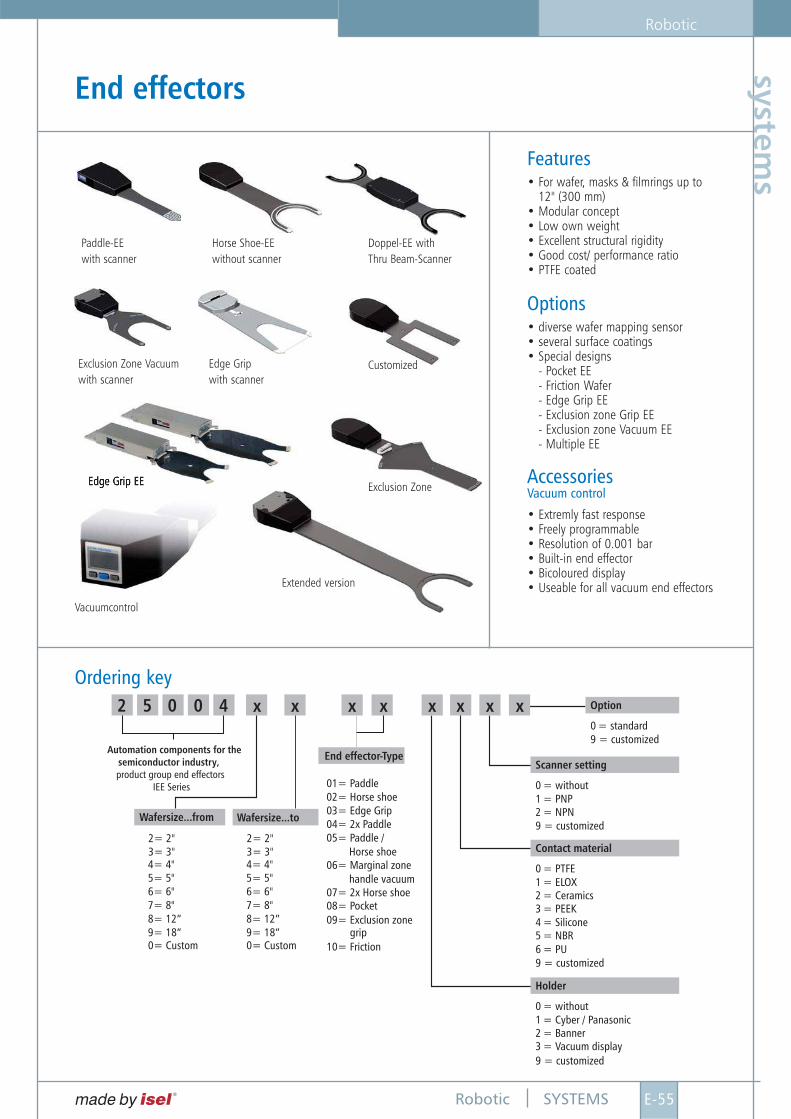
Features• For wafer, masks & filmrings up to
12" (300 mm)• Modular concept• Low own weight• Excellent structural rigidity• Good cost/ performance ratio• PTFE coated
Options• diverse wafer mapping sensor• several surface coatings• Special designs
- Pocket EE- Friction Wafer- Edge Grip EE- Exclusion zone Grip EE- Exclusion zone Vacuum EE- Multiple EE
Accessories Vacuum control
• Extremly fast response• Freely programmable• Resolution of 0.001 bar• Built-in end effector• Bicoloured display• Useable for all vacuum end effectors
Ordering key
End effectors
2 05 4 Option
Scanner setting
Contact material
Holder
0 = standard
0 = without
0 = PTFE
0 = without
3 = PEEK
3 = Vacuum display
1 = PNP
1 = ELOX
1 = Cyber / Panasonic
4 = Silicone
2 = NPN
2 = Ceramics
2 = Banner
5 = NBR6 = PU
9 = customized
9 = customized
9 = customized
9 = customized
Automation components for thesemiconductor industry,product group end effectors
IEE Series
Wafersize...from Wafersize...to
5= 5" 5= 5"
3= 3" 3= 3"4= 4" 4= 4"
2= 2" 2= 2"
6= 6" 6= 6"
0= Custom 0= Custom
7= 8" 7= 8"8= 12” 8= 12”9= 18” 9= 18”
End effector-Type
01= Paddle02= Horse shoe03= Edge Grip04= 2x Paddle05= Paddle /
06= Marginal zone
07= 2x Horse shoe08= Pocket
09= Exclusion zone
10= Friction
xxxxxxx x
Horse shoe
handle vacuum
grip
0
Paddle-EE with scanner
Horse Shoe-EE without scanner
Doppel-EE with Thru Beam-Scanner
CustomizedExclusion Zone Vacuumwith scanner
Edge Gripwith scanner
Exclusion Zone
Extended version
Vacuumcontrol
Edge Grip EE
SYSTEMS
Robotic
E-56 Robotic
syst
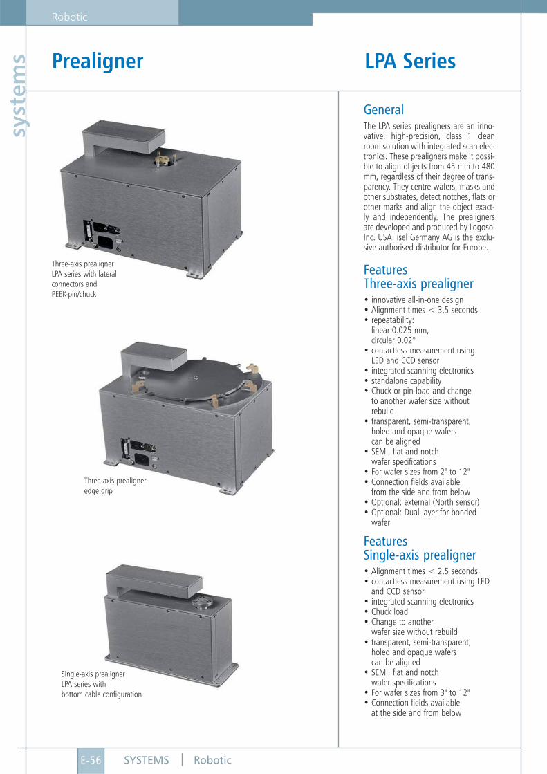
ems Prealigner LPA Series
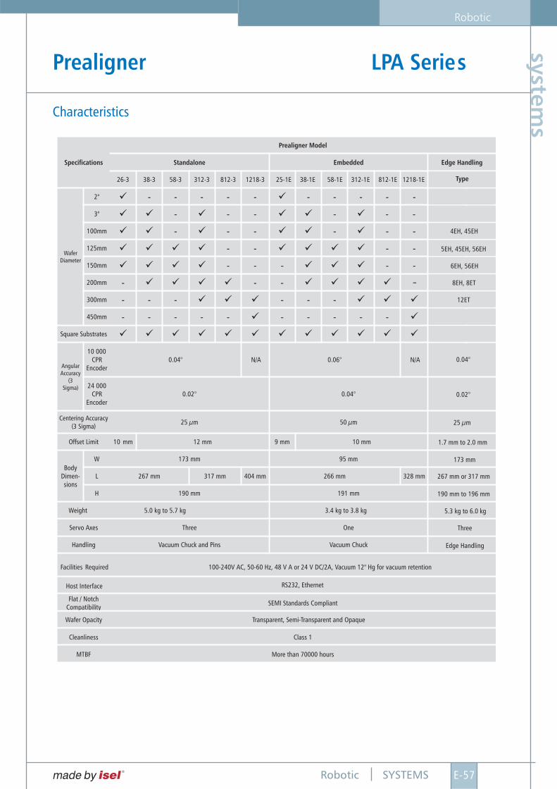
GeneralThe LPA series prealigners are an inno-vative, high-precision, class 1 cleanroom solution with integrated scan elec-tronics. These prealigners make it possi-ble to align objects from 45 mm to 480mm, regardless of their degree of trans-parency. They centre wafers, masks andother substrates, detect notches, flats orother marks and align the object exact-ly and independently. The prealignersare developed and produced by LogosolInc. USA. isel Germany AG is the exclu-sive authorised distributor for Europe.
FeaturesThree-axis prealigner• innovative all-in-one design• Alignment times < 3.5 seconds• repeatability:
linear 0.025 mm,circular 0.02°
• contactless measurement usingLED and CCD sensor
• integrated scanning electronics• standalone capability• Chuck or pin load and change
to another wafer size withoutrebuild
• transparent, semi-transparent,holed and opaque waferscan be aligned
• SEMI, flat and notchwafer specifications
• For wafer sizes from 2" to 12"• Connection fields available
from the side and from below• Optional: external (North sensor)• Optional: Dual layer for bonded
wafer
FeaturesSingle-axis prealigner• Alignment times < 2.5 seconds• contactless measurement using LED
and CCD sensor• integrated scanning electronics• Chuck load• Change to another
wafer size without rebuild• transparent, semi-transparent,
holed and opaque waferscan be aligned
• SEMI, flat and notchwafer specifications
• For wafer sizes from 3" to 12"• Connection fields available
at the side and from below
Three-axis prealigner LPA series with lateralconnectors andPEEK-pin/chuck
Single-axis prealigner LPA series withbottom cable configuration
Three-axis prealigner edge grip
SYSTEMS
Robotic
E-57Robotic
systems
Prealigner LPA Series
Characteristics
SYSTEMS
Robotic
E-58 Robotic
syst
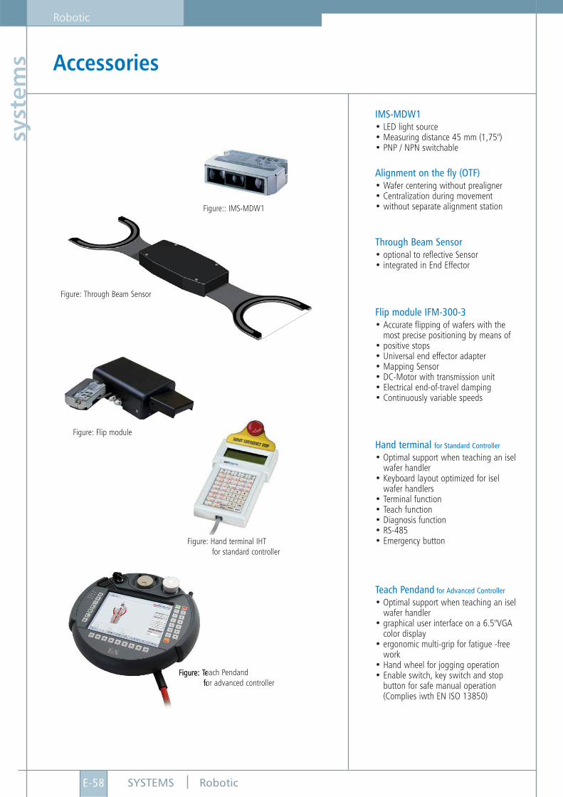
ems Accessories
IMS-MDW1• LED light source• Measuring distance 45 mm (1,75")• PNP / NPN switchable
Alignment on the fly (OTF)• Wafer centering without prealigner• Centralization during movement• without separate alignment station
Through Beam Sensor• optional to reflective Sensor• integrated in End Effector
Flip module IFM-300-3• Accurate flipping of wafers with the
most precise positioning by means of• positive stops• Universal end effector adapter• Mapping Sensor• DC-Motor with transmission unit• Electrical end-of-travel damping• Continuously variable speeds
Hand terminal for Standard Controller
• Optimal support when teaching an isel wafer handler
• Keyboard layout optimized for isel wafer handlers
• Terminal function• Teach function• Diagnosis function• RS-485• Emergency button
Teach Pendand for Advanced Controller
• Optimal support when teaching an isel wafer handler
• graphical user interface on a 6.5"VGA color display
• ergonomic multi-grip for fatigue -free work
• Hand wheel for jogging operation• Enable switch, key switch and stop
button for safe manual operation (Complies iwth EN ISO 13850)
Figure: Flip module
Figure: Hand terminal IHTfor standard controller
Figure:: IMS-MDW1
Figure: Through Beam Sensor
Figure: Teach Pendandfor advanced controller