Einsteckschloss mit Panikfunktion Mortise lock with panic ... · Der Einsatz von serienmäßigen...
24
Einsteckschloss mit Panikfunktion für 1- und 2-flügelige Rohrrahmentüren Montage- und Wartungsanleitung Mortise lock with panic function for 1 and 2 leaf tubular frame doors Installation and servicing manual Serie 100 0432-CPR-000037-01 EN 179 : 2008 377B1322 B 0432-CPR-000037-02 EN 1125 : 2008 377B1322 B LE/DOP-Nr. 003-01-DE 2016 A/B LE/DOP-Nr. 002-01-DE 2016 A/B 0432-CPR-000037-01 EN 179 : 2008 377B1322 A 0432-CPR-000037-02 EN 1125 : 2008 377B1322 A LE/DOP-Nr. 003-01-DE 2016 A/B LE/DOP-Nr. 002-01-DE 2016 A/B 0432-CPR-000037-01 EN 179 : 2008 377B1322 C 0432-CPR-000037-02 EN 1125 : 2008 377B1322 C 2016 LE/DOP-Nr. 002-01-DE 2016 LE/DOP-Nr. 003-01-DE A/B A/B
Transcript of Einsteckschloss mit Panikfunktion Mortise lock with panic ... · Der Einsatz von serienmäßigen...

Einsteckschloss mit Panikfunktion für 1- und 2-fl ügelige RohrrahmentürenMontage- und Wartungsanleitung
Mortise lock with panic function for 1 and 2 leaf tubular frame doorsInstallation and servicing manual
Serie 100
K0200126 / 100er Serie EN 179/1125 1-flg.
0432-CPR-000037-01EN 179 : 2008 3 7 7 B 1 3 2 2 B
0432-CPR-000037-02EN 1125 : 2008 3 7 7 B 1 3 2 2 B
LE/DOP-Nr. 003-01-DE
2016A/B
LE/DOP-Nr. 002-01-DE 2016
A/B K0200127 / 100er Serie EN 179/1125 2-flg.
0432-CPR-000037-01
EN 179 : 2008 3 7 7 B 1 3 2 2 A
0432-CPR-000037-02
EN 1125 : 2008 3 7 7 B 1 3 2 2 ALE/DOP-Nr. 003-01-DE
2016A/B
LE/DOP-Nr. 002-01-DE 2016
A/BK0200128 / 100er Serie EN 179/1225 -Standflügel
0432-CPR-000037-01
EN 179 : 2008 3 7 7 B 1 3 2 2 C
0432-CPR-000037-02
EN 1125 : 2008 3 7 7 B 1 3 2 2 C
2016
LE/DOP-Nr. 002-01-DE 2016
LE/DOP-Nr. 003-01-DE
A/B
A/B
2
Serie 100 Einsteckschloss mit Panikfunktion
Serie 100 Mortise lock with panic function
WSS – Wilh. Schlechtendahl & Söhne GmbH & Co. KG
InhaltsverzeichnisAllgemeines ...............................Seite 3
Produktbeschreibung .................Seite 3Auflistung der Schlösser ........Seite 3Anwendungsbereich ..............Seite 4Optionales Zubehör...............Seite 4
Wichtige Hinweise und Sicherheitsmaßnahmen ..............Seite 6
Restrisiken .............................Seite 8
Vor der Montage .......................Seite 8Allgemeines ...........................Seite 8Hinweise zur Bearbeitung der Tür ...................................Seite 8
Montage ....................................Seite 8Allgemeines ...........................Seite 8Montage der Komponenten ..Seite 8Schloss ohne Zusatzfalle ........Seite 9Schloss mit Zusatzfalle oben Teil 1: Schloss ........................Seite 10Schloss mit Zusatzfalle oben Teil 2: Zusatzfalle ...................Seite 11Schloss mit Zusatzfalle oben Teil 3: Stangenberechnung ....Seite 12Panik-Gegenkasten Teil 1: Gegenkasten ...............Seite 13Panik-Gegenkasten Teil 2: Zubehör ......................Seite 14Panik-Gegenkasten Teil 3: Stangenberechnung ....Seite 15Panik-Gegenkasten mit E-Öffner Teil 1: Gegenkasten ...............Seite 16Panik-Gegenkasten mit E-Öffner Teil 2: Stangenberechnung ....Seite 17Panik-Gegenkasten mit E-Öffner und Schnäpper Teil 3: Stangenberechnung ....Seite 18Schließblech...........................Seite 19Schließblech mit E-Öffner .....Seite 19
Inbetriebnahme ........................Seite 20
Wartung und Instandhaltung ....Seite 20
Entsorgung.................................Seite 21
Gebrauchshinweise ....................Seite 21
Dokumentation ..........................Seite 22
Table of contentGeneral ......................................Page 3
Product description ....................Page 3List of locks ............................Page 3Area of application ................Page 4Optional accessories ..............Page 4
Important information and safety measures .........................Page 6
Residual risk ...........................Page 8
Before installation ......................Page 8General ..................................Page 8Tips for processing the door ..Page 8
Installation .................................Page 8General ..................................Page 8Installation of components ....Page 8Lock without additional latch ..Page 9Lock with with additional top latch bolt Part 1: Lock ...........................Page 10Lock with with additional top latch bolt Part 2: additional top latch bolt . Page 11Lock with with additional top latch bolt Part 3: Calculation of the rod ..Page 12Panic strike box Part 1: Strike box ...................Page 13Panic strike box Part 2: Accessories.................Page 14Panic strike box Part 3: Calculation of the rod ...Page 15Panic strike box with electric strike Part 1: Strike box ...................Page 16Panic strike box with electric strike Part 2: Calculation of the rod ...Page 17Panic strike box with electric strike and catch Part3: Calculation of the rod ...Page 18Strike plate .............................Page 19Strike plate with electric strike ..Page 19
Start-up procedure ....................Page 20
Service and Maintenance ...........Page 20
Disposal .....................................Page 21
Instructions for use ....................Page 21
Documentation ..........................Page 22
3
Serie 100 Einsteckschloss mit Panikfunktion
Serie 100 Mortise lock with panic function
WSS – Wilh. Schlechtendahl & Söhne GmbH & Co. KG
GeneralThese installation instructions are an essential part of the product. They contain important information about safety, installation and usage. Only use the product as described and for the indicated area of application. These instructions are to be handed to the user and/or operator after the installation and performance test. These instructions are to be kept for reference.
Product descriptionMortise lock with panic function for 1 and 2 leaf tubular frame doors.
Performance declaration reference:For DIN EN 179: LE/DoP-Nr. 002-01-GB For DIN EN 1125: LE/DoP-Nr. 003-01-GBhttp://www.wss.de/en/service/down-load/declaration-of-performance.html
ATTENTION! The safety features of this product are an essential requirement for its compliance with DIN EN 1125/179. No changes can be made that are not described in these instruc-tions.
List of locksThis manufacturer’s declaration applies to the following panic sets for tubular frame doors:
AllgemeinesDiese Montageanleitung ist Bestand-teil des Produkts. Sie enthält wichtige Angaben zu Sicherheit, Montage und Gebrauch. Benutzen Sie das Produkt nur wie beschrieben und für die angegebe-nen Einsatzbereiche. Diese Anleitung ist nach Montage und Funktionsprüfung dem Benutzer bzw. Betreiber zu übergeben. Sie ist zum Nachschlagen aufzubewahren.
ProduktbeschreibungEinsteckschloss mit Panikfunktion für 1- und 2-flügelige Rohrrahmentüren
Verweis auf Leistungserklärung: Für DIN EN 179: LE/DoP-Nr. 002-01-DE Für DIN EN 1125: LE/DoP-Nr. 003-01-DEwww.wss.de/service/download/ leistungserklaerungen.html
ACHTUNG! Die Sicherheits-merkmale dieses Produkts sind eine wesentliche Voraussetzung für dessen Übereinstimmung mit DIN EN 1125/179. Es dürfen keinerlei Veränderungen vorgenommen werden, die nicht in dieser Anleitung beschrieben sind.
Auflistung der SchlösserDiese Herstellererklärung gilt für folgende Paniksets im Rohrrahmenbereich:
Art.-Nr.Art.-N°
Anzahl FlügelNumber of leaves
FunktionFunction
Set 1 01.200/20101.202/20301.204/205
111
EDB
Set 2 01.206/20701.208/209
11
EB
Set 3 01.210/21101.212/21301.214/215
222
EDB
Set 4 01.216/21701.218/219
22
EB
Set 5 01.220/22101.222/223
22
EB
Set 6 01.224/22501.226/227
22
EB
In diesen Sets sind folgende Schlösser und Gegenkästen etc. enthalten:
Art.-Nr.Art.-Nr.
Anzahl FlügelNumber of leaves
FunktionFunction
Dornmaß mmBackset mm
Panik-EinsteckschlossPanic-mortise lock
01.112/113 1 B 30–45
Panik-EinsteckschlossPanic-mortise lock
01.114/115 1 E 30–45
Panik-EinsteckschlossPanic-mortise lock
01.116/117 1 D 30–45
Panik-EinsteckschlossPanic-mortise lock
01.118/119 2 B 30–45
Panik-EinsteckschlossPanic-mortise lock
01.120/121 2 E 30–45
Panik-EinsteckschlossPanic-mortise lock
01.122/123 2 D 30–45
Panik-EinsteckschlossPanic-mortise lock
01.132/133 1 E 30–45
Panik-EinsteckschlossPanic-mortise lock
01.134/135 1 B 30–45
Panik-EinsteckschlossPanic-mortise lock
01.136/137 2 E 30–45
The following locks and keeps are included in these sets:
4
Serie 100 Einsteckschloss mit Panikfunktion
Serie 100 Mortise lock with panic function
WSS – Wilh. Schlechtendahl & Söhne GmbH & Co. KG
Art.-Nr.Art.-Nr.
Anzahl FlügelNumber of leaves
FunktionFunction
Dornmaß mmBackset mm
Panik-EinsteckschlossPanic-mortise lock
01.138/139 2 B 30–45
Panik-GegenkastenPanic-keeps
01.144 2 – 30–45, 55, 65
Panik-GegenkastenPanic-keeps
01.146/147 2 – 30–45, 55, 65
SchaltschlossTop lock
01.141.---.426 2 – –
SchnäpperCatch
01.141.22/24--.010
2 – –
ACHTUNG! Es dürfen keine zusätzlichen oder anderen Verschlüsse außerhalb der oben genannten Artikel bzw. außerhalb der Norm DIN EN 179 und DIN EN 1125 installiert werden, sofern nicht vorher die Zustimmung der zuständigen Genehmigungs behörde ein-geholt wurde. Ausgenommen Fluchttür-steuerungen gemäß den entsprechenden Normen bzw. Zulassungen. Dies betrifft nicht die Installation von Türschließern.
AnwendungsbereichDie Panikschlösser von WSS kommen überall dort zum Einsatz, wo Türen in Flucht- oder Rettungswegen eingesetzt werden.Hauptaufgabe dieses Produktes ist es, Menschen leben in Flucht- bzw. Panik-situationen zu retten. Das wichtigste Merkmal ist hierbei, das Öffnen der Tür mit nur geringen Anstrengungen von Hand oder durch Körperdruck zu er-möglichen, auch wenn z. B. bei Dunkel-heit und Rauch eine Menschen menge in Panik die Tür unter Druck setzt.
Ausschluss nicht bestimmungsgemäßer Verwendungen:Der Einsatz von serienmäßigen Panik-schlössern für Rohrrahmentüren und de-ren Zubehör ist nicht bestimmungsgemäß � bei Umgebungstemperaturen unter -20 °C bzw. über +100 °C
� bei Konstruktionen, die nicht für eine Panik funktion geeignet sind
� bei Türen mit folgenden Merkmalen: - Türgewicht über 320 kg - Türhöhe über 3.000 mm - Türbreite über 1.600 mm
Optionales Zubehör
ACHTUNG! Die Befestigungsvor-schriften und Anleitungen der Drücker-hersteller sind zu beachten. Sollten die Drücker nicht Bestandteil der Bestellung und Lieferung von WSS sein, so hat der Händler bzw. der Hersteller des Türelementes eigenverantwortlich sicher zu stellen, dass nur die geprüften und zugelassenen Drücker eingesetzt werden.
ATTENTION! No additional locks or those other than the items listed above and/or outside the standard DIN EN 179 and DIN EN 1125 can be installed if no approval from the responsible approval authority has been obtained beforehand; with the excep-tion of escape door control systems in compliance with the corresponding standards and/or permits. This does not affect the installation of door closers.
Area of applicationWSS panic locks are used everywhere where doors are deployed in escape or emergency routes.The main function of this product is to save human lives during escape or panic situations. The most important feature hereby is to enable opening of the door with minimum effort by hand or body pressure, even if a panicking mass of people put pressure on the door e.g. in the dark or in smoke.
Exclusion of incorrect utilisation:The usage of standard panic locks for tubular frame doors and their acces-sories is not intended for use � at ambient temperatures under -20 °C and/or above +100 °C
� with constructs that are not intended to have a panic function
� for doors with the following features: - Door weight over 320 kg - Door height above 3,000 mm - Door width greater than 1,600 mm
Optional accessories
ATTENTION! The handle manufacturer’s mounting regulations and instructions are to be observed. If the handles are not part of WSS’s order and supply, the dealer and/or manufac-turer of the door component is solely re-sponsible for ensuring that only certified and approved handles are used.
5
Serie 100 Einsteckschloss mit Panikfunktion
Serie 100 Mortise lock with panic function
WSS – Wilh. Schlechtendahl & Söhne GmbH & Co. KG
Inner actuating fittings:As per DIN EN 179 � Certified handles as per certificate item no. 0432-CPR-000037-01
As per DIN EN 1125 � Panic push-rod PD 79 item no. 01.690-693.----.---
� Panic rod handle PS 99 item no. 01.680-683.----.--- - No electronic knob cylinders are
permitted in conjunction with the PS 99 (risk of crushing fingers)!
- Absence of movement restrictions must always be tested for and/or verified with the PS 99!
Outer actuating fittings with connection to the panic system:As per DIN EN 179 � Certified handles according to EU
conformity certificate 0432-CPR-000037-01 identical to the inner handle.
As per DIN EN 1125 � Handles that have been certified e.g. as per DIN EN 1906, DIN EN 18273 and DIN EN 179, and therefore have a certain established quality standard.
You find additional components such as electric strike release, exterior fittings, special electronic knob cylinders, electronic cylinders and strike plates in the additional manufacturer‘s declaration on www.wss.de/en/service/download/manufacturers-declaration.
Innere Betätigungsvorrichtungen:Nach DIN EN 179 � geprüfte Drücker gemäß Zertifikat Art.-Nr. 0432-CPR-000037-01
Nach DIN EN 1125 � Panik-Druckstange PD 79 Art.-Nr. 01.690-693.----.---
� Panik-Stangengriff PS 99 Art.-Nr. 01.680-683.----.--- - In Verbindung mit dem PS 99 sind
keine elektronischen Knaufzylinder zulässig (Klemmgefahr der Finger)!
- Auch ist beim PS 99 immer eine Zwängungs freiheit bauseits zu prüfen bzw. nachzuweisen!
Äußere Betätigungsvorrichtungen mit Anbindung an das Paniksystem:Nach DIN EN 179 � Geprüfte Drücker gemäß EG-
Konformitäts zertifikat 0432-CPR-000037-01 identisch mit dem inneren Drücker.
Nach DIN EN 1125 � Drücker welche z.B. nach DIN EN 1906,
DIN EN 18273 und nach DIN EN 179 geprüft wurden und somit einen gewissen Qualitäts standard nachge-wiesen haben.
Ergänzende Beschlagkomponenten wie E-Öffner, Außenbeschläge, Elektronik-Sonderknaufzylinder, Elektronik-Zylinder und Schließbleche finden Sie in der ergänzenden Hersteller erklärung auf www.wss.de/service/download/Herstellererklärung.
6
Serie 100 Einsteckschloss mit Panikfunktion
Serie 100 Mortise lock with panic function
WSS – Wilh. Schlechtendahl & Söhne GmbH & Co. KG
Important informa-tion and safety measures
Prevent injuries, damages and malfunc-tion by following all instructions.
Panic locks for tubular frame doors from Wilh. Schlechtendahl & Söhne GmbH & Co. KG (hereafter referred to as WSS) plan the installation of single and double leaf doors.
� Before emergency exit and/or panic lock is installed on a fire protection and/or smoke protection door, the door should be inspected to ensure that the emergency lock is suitable and approved for this specific door (see Annex B DIN EN 1125 and DIN EN 179).
� Only persons familiar with the instal-lation and maintenance of panic locks can be commissioned to work on them. The contractor must commission such persons with installation and maintenance. They must know the relevant standards and regulations (e.g. DIN EN 1125, DIN EN 179 etc.) and have the relevant training.
� They must have read and understood the installation instructions issued by WSS.
� If more than one person is entrusted with the activity mentioned above, the contractor must designate a supervisor who is authorised to give instructions.
� Before beginning installation, check for completeness of all parts. Only use components that are free of defects.
� The door must be checked to ensure it opens correctly and/or easily with-out hindrance or exhibiting any delay.
� When using door seals it must be guaranteed that they do not impair the proper use of the door and/or the latching function of the door.
� For double-leaf rebated doors with central doorstop where both leaves are fitted with panic locks, it must be possible to open each leaf when its lock is activated. It must be ensured that the door leaf and fittings can move without restriction. The use of a pushing flap is provided for if necessary.
� For panic locks as per DIN EN 1125 it must be ensured that the right length is mounted. The largest possible rod length is to be selected, at least 60% of the door panel width must be available for triggering.
� Doors with glass inserts that are fitted with an emergency and/or panic lock, should be fitted with safety glazing (safety glass or laminated safety glass).
� Various fastening elements may be necessary, which deviate from those included in the scope of supply, in order to mount an emergency lock onto various types of doors. In this event, the fitter should select solid, durable fastening components that correspond to the requirements, and/or consult WSS.
� Emergency exit locks are not suitable for use on swinging doors.
� The handle or panic rod handle and/or panic push-rod should normally be installed between 900 mm and
Wichtige Hinweise und Sicherheitsmaß-nahmen
Vermeiden Sie Verletzungen, Schäden und Fehlfunktion indem Sie alle Anweisungen befolgen.
Panikschlösser für Rohrrahmentüren der Wilh. Schlechtendahl & Söhne GmbH & Co. KG (im folgenden WSS genannt) sind zum Einbau in ein- und zweiflügelige Türen vorgesehen.
� Bevor der Notausgangs- bzw. Panik-verschluss an einer Feuerschutz- bzw. Rauchschutztür installiert wird, muss überprüft werden, ob der Notaus-gangsverschluss für diese spezielle Tür geeignet und zugelassen ist (siehe Anhang B, DIN EN 1125 und DIN EN 179).
� Mit Einbau und Wartung der Panik-schlösser dürfen nur Personen be-auftragt werden, die hiermit vertraut sind. Sie müssen vom Unternehmer mit dem Einbau und der Wartung beauftragt sein. Sie müssen die ein-schlägigen Normen und Vorschriften (z.B. DIN EN 1125, DIN EN 179, etc.) kennen und entsprechend unterwiesen worden sein.
� Sie müssen die von WSS erstellte Montage anleitung gelesen und ver-standen haben.
� Ist mehr als eine Person mit einer der oben genannten Tätigkeiten betraut, so hat der Unternehmer einen Auf-sichtführenden zu bestimmen, der weisungsbefugt ist.
� Überprüfen Sie vor Beginn der Montage alle Teile auf Vollzähligkeit. Verwenden Sie nur einwandfreie Komponenten.
� Die Tür ist auf korrekte bzw. leichte und ungehinderte Öffnung zu prüfen und darf keinen Verzug aufweisen.
� Beim Einsatz von Türdichtungen muss gewährleistet sein, dass diese den bestimmungsgemäßen Gebrauch der Tür bzw. die Funktion des Türver-schlusses nicht beeinträchtigen.
� Bei zweiflügeligen Türen mit überfälz-tem Mittel anschlag, an denen beide Flügel mit Panikverschlüssen aus-gerüstet sind, muss sich jeder Flügel öffnen lassen, wenn sein Verschluss betätigt wird. Auf eine Zwängungs-freiheit der Türflügel und der Beschläge ist zu achten. Gegebenenfalls ist der Einsatz einer Mitnehmerklappe vorzusehen.
� Bei Panikverschlüssen nach DIN EN 1125 ist sicher zu stellen, dass die richtige Länge montiert wurde. Die größtmögliche wirksame Stangenlänge ist zu wählen, mindestens 60% der Türblattbreite müssen zur Auslösung zur Verfügung stehen.
� Türen mit Glaseinsätzen, die mit einem Notaus gangs- bzw. Panikver-schluss ausgerüstet werden, sollten mit einer Sicherheitsverglasung (Sicherheitsglas oder Verbund-sicherheitsglas) ausgerüstet sein.
� Für die Befestigung eines Notaus-gangsverschlusses an verschiedenen Türarten, können unterschiedliche Befestigungsteile erforderlich sein, die von denen im Lieferumfang ent-haltenen abweichen. Hierbei ist durch den Monteur eine, den Erfordernissen

7
Serie 100 Einsteckschloss mit Panikfunktion
Serie 100 Mortise lock with panic function
WSS – Wilh. Schlechtendahl & Söhne GmbH & Co. KG
1,100 mm above the surface of the finished floor. If it is known that the majority of users are small children, lowering the height of the handle should be considered.
� The locking rods must be set up and secured in such a way that secure intervention is guaranteed.
� It must be ensured that the protrusion in the drawn-in position does not hin-der the free movement of the door.
� If the panic door locks are intended to be mounted on double-leaf rebated doors with central doorstop and door closers, a door leaf coordinator as per DIN EN 1158 with pushing flap must be installed or a door leaf coordinator integrated into the locking system in order to guarantee the right closing sequence. This is particularly important for fire and smoke protection doors.
� If a door closer is installed, it must be ensured that it does not make it diffi-cult for children, handicapped persons and seniors to open the door.
� Floor locking hutches, strike plates and/or locking hutches must be installed according to the instructions so that conformity with the standard component is ensured. Deviations due to different models are only permitted after consulting WSS.
� The panic function is only guaranteed when the key has been removed.
� The use of knob cylinders together with the panic locks described here is only possible with electronic knob cylinders with a retracting mechanism for the locking nose that have been tested and approved by WSS, see page 5 for details.
� For panic doors as per DIN EN 1125, a sign with the inscription “Press” or “Press against the bar to open” or a pictogram should be put onto the inside of the door, directly above the horizontal
activation bar or on the activation bar itself. The colour should be white on a green background, similar to the pictogram Figure A1 in DIN EN 1125 (Point A.19).
entsprechend dauerhaft, solide Befestigung zu wählen, bzw. mit WSS Rücksprache zu halten.
� Notausgangsverschlüsse sind nicht für den Einsatz an Pendeltüren geeignet.
� Der Drücker oder der Panik-Stangen-griff bzw. die Panik-Druckstange sollte normaler weise in einer Höhe zwischen 900 mm und 1.100 mm über der Oberfläche des fertigen Fußbodens installiert werden. Falls bekannt ist, dass die Mehrheit der Benutzer kleine Kinder sind, sollte eine Reduzierung der Drückerhöhe in Betracht gezogen werden.
� Die Verriegelungsstangen müssen so eingestellt und gesichert werden, dass ein sicheres Eingreifen gewährleistet ist.
� Es muss beachtet werden, dass der Überstand in der hereingezogenen Stellung die freie Bewegung der Tür nicht behindert.
� Falls die zu befestigenden Paniktür-verschlüsse an zweiflügeligen Türen mit überfälzten Mittel anschlag und Türschließern vorgesehen sind, muss ein Schließfolgeregler nach DIN EN 1158 mit Mitnehmer klappe installiert werden, oder eine in die Schließanlage integrierte Schließfolge regelung, um die richtige Schließfolge der Tür zu gewährleisten. Dies ist für Feuerschutz- und Rauchschutztüren besonders wichtig.
� Falls ein Türschließer installiert wird, muss darauf geachtet werden, dass hierdurch die Betätigung der Tür durch Kinder, Behinderte und ältere Personen nicht erschwert wird.
� Vorgesehene Bodenschließmulden, Schließbleche bzw. Schließmulden müssen gemäß der Anleitung installiert werden, so dass die Übereinstimmung mit dem geprüften Norm element sichergestellt ist. Abweichungen auf-grund unterschiedlicher Ausführun-gen sind nur in Absprache mit WSS zulässig.
� Die Panikfunktion ist nur bei abgezo-genem Schlüssel gewährleistet.
� Der Einsatz von Knaufzylindern in Verbindung mit den hier beschriebe-nen Panikschlössern ist ausschließlich mit durch WSS geprüften und freige-gebenen elektronischen Knaufzylin-dern mit Rückstellmechanismus für die Schließnase möglich, Details siehe Seite 5.
� Bei Paniktüren nach DIN EN 1125 sollte an der Innenseite der Tür, unmittelbar oberhalb der horizontalen Betätigungs-stange, oder auf der Betätigungs-stange selbst, ein Schild mit der
Aufschrift „Drücken“ oder „Zum Öffnen gegen die Stange drücken“ oder ein Piktogramm vorgesehen werden. Die Farbe sollte weiß auf einem grünen Hinter grund sein, ähnlich dem Piktogramm Bild A1 in der DIN EN 1125 (Punkt A.19).
8
Serie 100 Einsteckschloss mit Panikfunktion
Serie 100 Mortise lock with panic function
WSS – Wilh. Schlechtendahl & Söhne GmbH & Co. KG
Residual riskWSS continually strives to improve its products and increase safety and functionality. The following risks cannot be covered by the design:
� WSS panic locks can only fulfil their function when they are mounted properly and serviced regularly.
� Unauthorised manipulation by third parties can lead to limitations to and loss of the safety function.
Before installationGeneralThe door manufacturer and/or the com-pany that has been commissioned with installation is responsible for ensuring that the door complies with the appli-cable standards and that the processing of the door is done in a professional manner.
Tips for processing the door � Make the drill holes and grooves ac-cording to the drawings on pages 12 to 20. The positioning of the locking system components depends on the door. Observe the installation instruc-tions for the fittings when making drill holes and grooves for handles, panic push-rod PD 79 or panic rod handle PS 99.
� Carefully deburr the drill holes and grooves.
InstallationGeneralThe counter sink in the stainless steel face plates are designed for M5 coun-tersunk head screws.
Installation of componentsInstallation and start-up can only be performed by expert personnel who have been instructed accordingly.
ATTENTION! The change of building components or the use of unauthorised foreign products or other accessories that have not been approved by WSS is not permitted. Non-compli-ance can lead to component damage and loss of warranty.
Assemble all components according to the drawing on pages 12 to 20 into the pre-made grooves and drill holes.
The fastening material is not included in the scope of delivery and must be provided from the factory.
Observe the installation instructions for assembly with the panic push-rod PD 79 or panic rod handle PS 99.
RestrisikenWSS ist ständig bemüht die Produkte zu verbessern und die Sicherheit und Funk-tionalität zu erhöhen. Folgende Risiken können konstruktiv nicht abgedeckt werden:
� Die Panikschlösser von WSS erfüllen nur dann ihre Funktion, wenn sie einwandfrei montiert und regelmäßig gewartet werden.
� Unerlaubte Manipulation durch Dritte kann eine Einschränkung oder den Verlust der Sicherheitsfunktion nach sich ziehen.
Vor der MontageAllgemeinesDer Türenhersteller bzw. das beauftrag-te Montage unternehmen ist dafür ver-antwortlich, dass die Tür den geltenden Normen entspricht und die Bearbeitung der Tür fachmännisch ausgeführt wird.
Hinweise zur Bearbeitung der Tür � Fertigen Sie die Bohrungen und Ausfrä-
sungen gemäß den Zeichnungen auf den Seiten 12 bis 20 an. Dabei ist die Positionierung der Komponenten des Schließsystems türabhängig. Beachten Sie für Bohrungen und Ausfräsungen für Drücker, Panik-Druckstange PD 79 oder Panik-Stangengriff PS 99 die Montageanleitungen dieser Beschläge.
� Entgraten Sie die Bohrungen und Ausfräsungen sorgfältig.
MontageAllgemeinesDie Senkungen in den Edelstahlstul-pen sind für M5 Senkkopfschrauben ausgelegt.
Montage der KomponentenMontage und Inbetriebnahme nur durch entsprechend unterwiesenes Fachper-sonal.
ACHTUNG! Die Veränderung von Bau teilen oder die Verwendung von nicht zugelassenen Fremdprodukten oder anderem durch WSS nicht zuge-lassenen Zubehörs ist nicht gestattet. Zuwiderhandlung kann zu Beschädigungen der Komponenten und zum Verlust der Gewährleistung führen.
Bauen Sie alle Komponenten gemäß den Zeichnungen auf den Seiten 12 bis 20 in die vorgefertigten Ausfräsungen und Bohrungen ein.
Das Befestigungsmaterial ist nicht im Lieferumfang enthalten und muss werk-seitig gestellt werden.
Beachten Sie für die Montage mit der Panik-Druckstange PD 79 oder dem Panik-Stangengriff PS 99 die Montage-anleitungen dieser Beschläge.
9
Serie 100 Einsteckschloss mit Panikfunktion
Serie 100 Mortise lock with panic function
WSS – Wilh. Schlechtendahl & Söhne GmbH & Co. KG
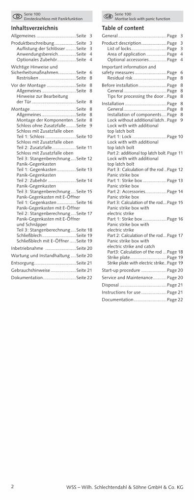
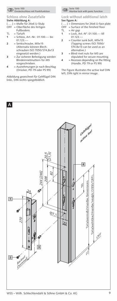
Lock without additional latchSee figure A:[ .... ] = Dimensions for 24x6 U-face plateOFF = Surface of the finished floorTL = Air gap1 = Lock, Art.-N°: 01.100.--- till
01.123.---2 = Counter sunk bolt, M5x15
(Tapping screws ISO 7050/ST4.8x13 can be used as an alternative.)
3 = Blind rivet nuts for M5 are stipulated for secure mounting.
4 = Recesses depending on the fitting (Handle, PD 79 or PS 99)
The Figure illustrates the active leaf DIN left, DIN right in mirror image.
A
[21,
5]
244
[246
]20
820
,5
82
92
Drü
cker
maß
/Han
dle
dim
ensi
ons
Drü
cker
höhe
/Han
dle
heig
ht (
1050
OFF
)
OFF
TL
Dornm
aßBa
ckse
t
Ø7,1
20
24
270
1
2
3
4
Schloss ohne ZusatzfalleSiehe Abbildung A:[ .... ] = Maße für 24x6 U-StulpOFF = Oberfläche des fertigen
FußbodensTL = Türluft1 = Schloss, Art.-Nr.: 01.100.--- bis
01.123.---2 = Senkschraube, M5x15
(Alternativ können Blech-schrauben ISO 7050/ST4,8x13 eingesetzt werden.)
3 = Zur sicheren Befestigung werden Blind einniet muttern für M5 vorgeschrieben.
4 = Ausnehmungen je nach Beschlag (Drücker, PD 79 oder PS 99)
Abbildung gezeichnet für Gehflügel DIN links, DIN rechts spiegelbildlich.
10
Serie 100 Einsteckschloss mit Panikfunktion
Serie 100 Mortise lock with panic function
WSS – Wilh. Schlechtendahl & Söhne GmbH & Co. KG
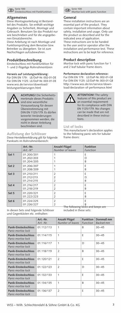
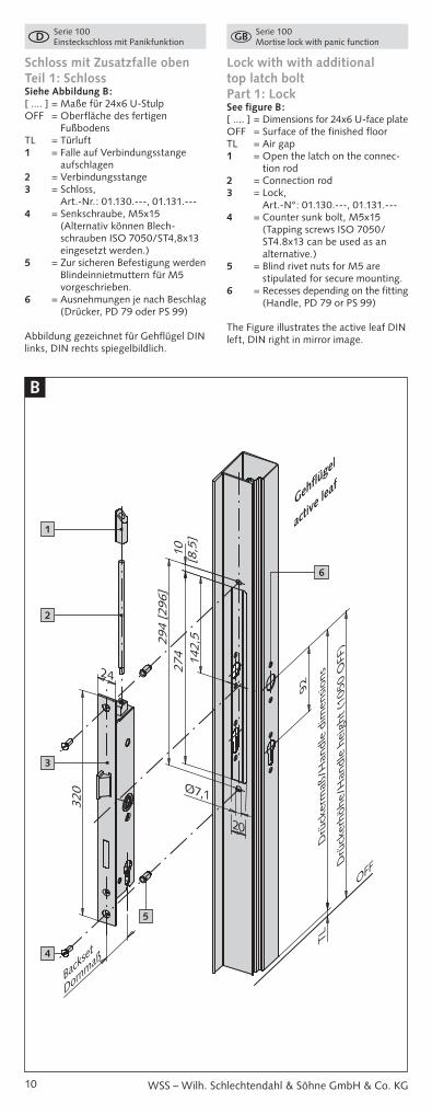
Schloss mit Zusatzfalle oben Teil 1: SchlossSiehe Abbildung B:[ .... ] = Maße für 24x6 U-StulpOFF = Oberfläche des fertigen
FußbodensTL = Türluft1 = Falle auf Verbindungsstange
aufschlagen2 = Verbindungsstange3 = Schloss,
Art.-Nr.: 01.130.---, 01.131.---4 = Senkschraube, M5x15
(Alternativ können Blech-schrauben ISO 7050/ST4,8x13 eingesetzt werden.)
5 = Zur sicheren Befestigung werden Blind einnietmuttern für M5 vorgeschrieben.
6 = Ausnehmungen je nach Beschlag (Drücker, PD 79 oder PS 99)
Abbildung gezeichnet für Gehflügel DIN links, DIN rechts spiegelbildlich.
Lock with with additional top latch bolt Part 1: LockSee figure B:[ .... ] = Dimensions for 24x6 U-face plateOFF = Surface of the finished floorTL = Air gap1 = Open the latch on the connec-
tion rod2 = Connection rod3 = Lock,
Art.-N°: 01.130.---, 01.131.---4 = Counter sunk bolt, M5x15
(Tapping screws ISO 7050/ST4.8x13 can be used as an alternative.)
5 = Blind rivet nuts for M5 are stipulated for secure mounting.
6 = Recesses depending on the fitting (Handle, PD 79 or PS 99)
The Figure illustrates the active leaf DIN left, DIN right in mirror image.
B
24
320
142,
5
92
Drü
cker
maß
/Han
dle
dim
ensi
ons
Drü
cker
höhe
/Han
dle
heig
ht (
1050
OFF
)
OFF
TL
Dornm
aß
1027
429
4 [2
96]
Ø7,1
20
[8,5
]
Back
set4
3
2
1
6
5
11
Serie 100 Einsteckschloss mit Panikfunktion
Serie 100 Mortise lock with panic function
WSS – Wilh. Schlechtendahl & Söhne GmbH & Co. KG
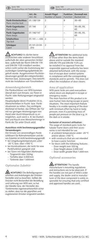
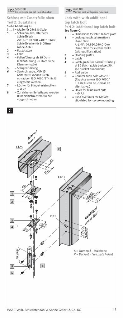
Schloss mit Zusatzfalle oben Teil 2: ZusatzfalleSiehe Abbildung C:[ .... ] = Maße für 24x6 U-Stulp1 = Schließmulde, alternativ
Schließblech Art.-Nr.: 01.820.240.010 bzw. Schließbleche für E-Öffner (ohne Abb.)
2 = Rastplatten3 = Falle4 = Fallenführung ab 35 Dorn
(Fallenführung 30 Dorn siehe Klammermaße)
5 = Stangenführung6 = Senkschraube, M5x15
(Alternativ können Blech-schrauben ISO 7050/ST4,8x13 eingesetzt werden.)
7 = Löcher für Blindeinnietmuttern = Ø 7,1
8 = Zur sicheren Befestigung werden Blindeinnietmuttern für M5 vorgeschrieben.
Lock with with additional top latch bolt Part 2: additional top latch boltSee figure C:[ .... ] = Dimensions for 24x6 U-face plate1 = Locking hutch, alternatively
Strike plate Art.-N°: 01.820.240.010 or Strike plate for electric strike (without illustration)
2 = Dividing plates3 = Latch4 = Latch guide for backset starting
at 35 (latch guide backset 30, see bracket dimensions)
5 = Rod guide6 = Counter sunk bolt, M5x15
(Tapping screws ISO 7050/ST4.8x13 can be used as an alternative.)
7 = Holes for blind rivet nuts = Ø 7,1
8 = Blind rivet nuts for M5 are stipulated for secure mounting.
C
Ø20
Ø25
2929
Ø13
(17,5
)
(17,5
)
20
24
2525
X
20
20
65
78 [
95]
40
60
(50)
[35]
[35]
1
7
2
3
4
5
6
8
X = Dornmaß - StulphöheX = Backset - face plate height
12
Serie 100 Einsteckschloss mit Panikfunktion
Serie 100 Mortise lock with panic function
WSS – Wilh. Schlechtendahl & Söhne GmbH & Co. KG
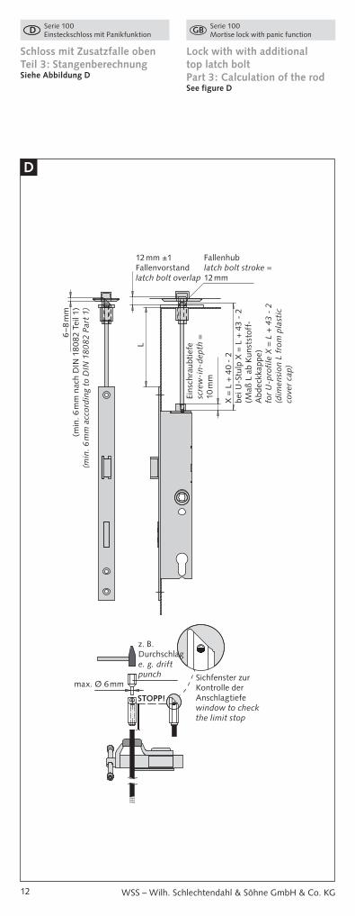
Schloss mit Zusatzfalle oben Teil 3: StangenberechnungSiehe Abbildung D
Lock with with additional top latch bolt Part 3: Calculation of the rodSee figure D
D
STOPP!
Fallenhublatch bolt stroke = 12 mm
Eins
chra
ubti
efe
scre
w-i
n-de
pth
=
10 m
m
6–8
mm
(min
. 6 m
m n
ach
DIN
18
082
Tei
l 1)
(min
. 6 m
m a
ccor
ding
to
DIN
18
082
Par
t 1)
L
X =
L +
40
- 2
bei U
-Stu
lp X
= L
+ 4
3 -
2(M
aß L
ab
Kun
stst
off-
Abd
eckk
appe
)fo
r U
-pro
file
X =
L +
43
- 2
(dim
ensi
on L
fro
m p
last
ic
cove
r ca
p)
12 mm ±1Fallenvorstandlatch bolt overlap
max. Ø 6 mm
z. B. Durchschlage. g. drift punch Sichfenster zur
Kontrolle der Anschlagtiefewindow to check the limit stop
13
Serie 100 Einsteckschloss mit Panikfunktion
Serie 100 Mortise lock with panic function
WSS – Wilh. Schlechtendahl & Söhne GmbH & Co. KG
X =
L +
40
- 2
bei U
-Stu
lp X
= L
+ 4
3 -
2(M
aß L
ab
Kun
stst
off-
Abd
eckk
appe
)fo
r U
-pro
file
X =
L +
43
- 2
(dim
ensi
on L
fro
m p
last
ic
cove
r ca
p)
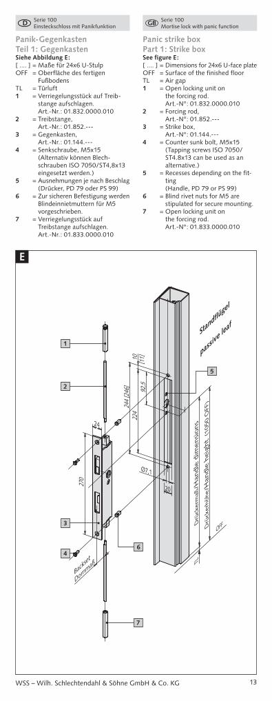
Panik-Gegenkasten Teil 1: GegenkastenSiehe Abbildung E:[ .... ] = Maße für 24x6 U-StulpOFF = Oberfläche des fertigen
FußbodensTL = Türluft1 = Verriegelungsstück auf Treib-
stange aufschlagen. Art.-Nr.: 01.832.0000.010
2 = Treibstange, Art.-Nr.: 01.852.---
3 = Gegenkasten, Art.-Nr.: 01.144.---
4 = Senkschraube, M5x15 (Alternativ können Blech-schrauben ISO 7050/ST4,8x13 eingesetzt werden.)
5 = Ausnehmungen je nach Beschlag (Drücker, PD 79 oder PS 99)
6 = Zur sicheren Befestigung werden Blindeinnietmuttern für M5 vorgeschrieben.
7 = Verriegelungsstück auf Treibstange aufschlagen. Art.-Nr.: 01.833.0000.010
Panic strike box Part 1: Strike boxSee figure E:[ .... ] = Dimensions for 24x6 U-face plateOFF = Surface of the finished floorTL = Air gap1 = Open locking unit on
the forcing rod. Art.-N°: 01.832.0000.010
2 = Forcing rod, Art.-N°: 01.852.---
3 = Strike box, Art.-N°: 01.144.---
4 = Counter sunk bolt, M5x15 (Tapping screws ISO 7050/ST4.8x13 can be used as an alternative.)
5 = Recesses depending on the fit-ting (Handle, PD 79 or PS 99)
6 = Blind rivet nuts for M5 are stipulated for secure mounting.
7 = Open locking unit on the forcing rod. Art.-N°: 01.833.0000.010
E
OFF
TL
[11]
Ø7,1
20
Dornm
aßBa
ckse
t
24
270
224
244
[246
]10
92,5
Drü
cker
höhe
/Han
dle
heig
ht (
1050
OFF
)
Drü
cker
maß
/Han
dle
dim
ensi
ons
3
6
7
4
2
1
5
14
Serie 100 Einsteckschloss mit Panikfunktion
Serie 100 Mortise lock with panic function
WSS – Wilh. Schlechtendahl & Söhne GmbH & Co. KG
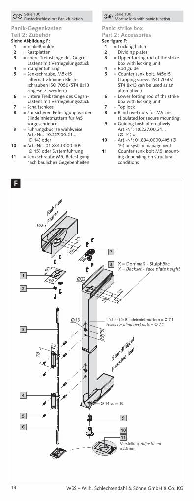
Panik-Gegenkasten Teil 2: ZubehörSiehe Abbildung F: 1 = Schließmulde 2 = Rastplatten 3 = obere Treibstange des Gegen-
kastens mit Verriegelungsstück 4 = Stangenführung 5 = Senkschraube, M5x15
(alternativ können Blech-schrauben ISO 7050/ST4,8x13 eingesetzt werden.)
6 = untere Treibstange des Gegen-kastens mit Verriegelungsstück
7 = Schaltschloss 8 = Zur sicheren Befes tigung werden
Blindeinnietmuttern für M5 vorgeschrieben.
9 = Führungsbuchse wahlweise Art.-Nr.: 10.227.00.21... (Ø 14) oder
10 = Art.-Nr.: 01.834.0000.405 (Ø 15) oder Systemführung
11 = Senkschraube M5, Befestigung nach baulichen Gegebenheiten
Panic strike box Part 2: AccessoriesSee figure F: 1 = Locking hutch 2 = Dividing plates 3 = Upper forcing rod of the strike
box with locking unit 4 = Rod guide 5 = Counter sunk bolt, M5x15
(Tapping screws ISO 7050/ST4.8x13 can be used as an alternative.)
6 = Lower forcing rod of the strike box with locking unit
7 = Top lock 8 = Blind rivet nuts for M5 are
stipulated for secure mounting. 9 = Guiding bush alternatively
Art.-N°: 10.227.00.21... (Ø 14) or
10 = Art.-N°: 01.834.0000.405 (Ø 15) or system management
11 = Counter sunk bolt M5, mount-ing depending on structural conditions
F
19
19
X
2929
20
20
60
40
20
78
Ø25
Ø13
Ø22
24
Verstellung Adjustment ±2,5 mm
Ø 14 oder 15
Löcher für Blindeinnietmuttern = Ø 7.1Holes for blind rivet nuts = Ø 7,1
1
2
3
4
5
6
7
8
9
10
11
X = Dornmaß - StulphöheX = Backset - face plate height
15
Serie 100 Einsteckschloss mit Panikfunktion
Serie 100 Mortise lock with panic function
WSS – Wilh. Schlechtendahl & Söhne GmbH & Co. KG
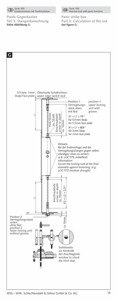
Panik-Gegenkasten Teil 3: StangenberechnungSiehe Abbildung G:
Panic strike box Part 3: Calculation of the rodSee figure G:
G
OFF
L1
4
L2
Oberkante Schaltschlossupper edge switch lock
5,5 bzw. 3 mm Stulp/Face plate
Hinweis:Bei der Endmontage sind die Verriegelungs stangen gegen selbst-ständiges Lösen zu sichern. (z.B. LOCTITE-mittelfest)Information:Secure the locking rods at the final assembly against loosening. (e.g. LOCTITE medium strength)
Sichtfenster zur Kontrolle der Anschlagtiefewindow to check the limit stop
Position 2Verriegelungsstück unten, ohne Nutposition 2lower locking unit without groove
X2
= L
2 +
2,5
±1
ca. 1
0 m
m
Eins
chra
ubti
efe
scre
w-i
n-de
pth
ca. 1
0 m
m
Eins
chra
ubti
efe
scre
w-i
n-de
pth
ca. 1
0 m
m
Hub
/Str
oke
ca.
12
mm
STOPP!
X1 = L1 + 11±1
für 5,5 mm Stulp for 5.5 mm face plate
X1 = L1 + 8,5±1
für 3 mm Stulp for 3 mm face plate
Position 1, Verriegelungs-stück oben, mit Nut
position 1upper locking unit with groove
16
Serie 100 Einsteckschloss mit Panikfunktion
Serie 100 Mortise lock with panic function
WSS – Wilh. Schlechtendahl & Söhne GmbH & Co. KG
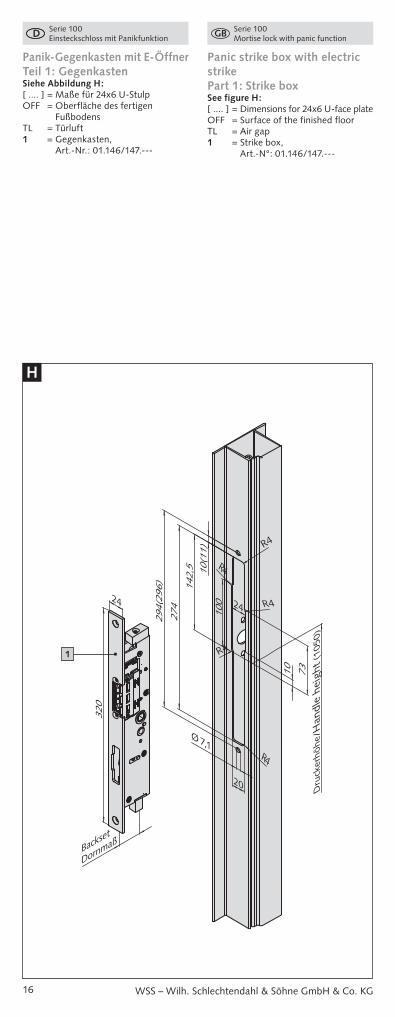
Panik-Gegenkasten mit E-Öffner Teil 1: GegenkastenSiehe Abbildung H:[ .... ] = Maße für 24x6 U-StulpOFF = Oberfläche des fertigen
FußbodensTL = Türluft1 = Gegenkasten,
Art.-Nr.: 01.146/147.---
Panic strike box with electric strike Part 1: Strike boxSee figure H:[ .... ] = Dimensions for 24x6 U-face plateOFF = Surface of the finished floorTL = Air gap1 = Strike box,
Art.-N°: 01.146/147.---
H
24
320
24
20
10 73
274
100
Dru
cker
höhe
/Han
dle
heig
ht (
1050
)
294(
296)
10(1
1)14
2,5
DornmaßBackset
Ø 7,1
R4
R4
R4
R4
R41
17
Serie 100 Einsteckschloss mit Panikfunktion
Serie 100 Mortise lock with panic function
WSS – Wilh. Schlechtendahl & Söhne GmbH & Co. KG
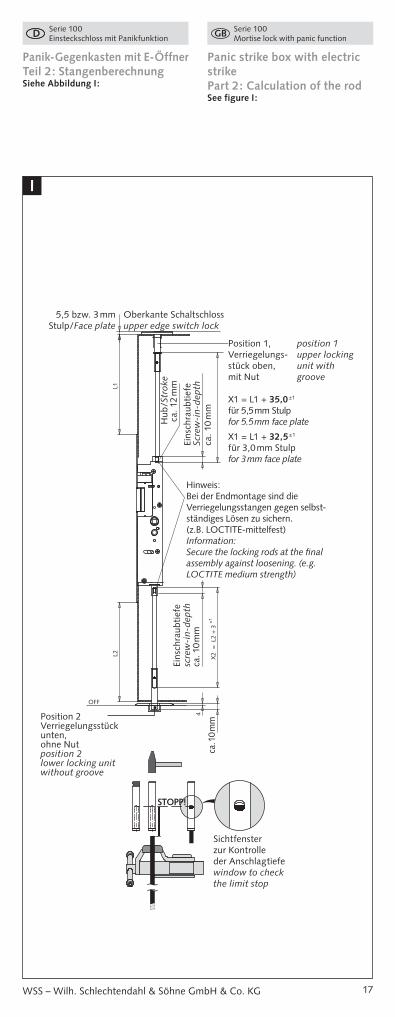
Panik-Gegenkasten mit E-Öffner Teil 2: StangenberechnungSiehe Abbildung I:
Panic strike box with electric strike Part 2: Calculation of the rodSee figure I:
I
OFF
X2
= L
2 +
3 ±
1
L1
4
L2
ca. 1
0 m
m
Eins
chra
ubti
efe
Scre
w-i
n-de
pth
ca. 1
0 m
m
Hub
/Str
oke
ca.
12
mm
5,5 bzw. 3 mm Stulp/Face plate
Oberkante Schaltschlossupper edge switch lock
X1 = L1 + 35,0±1
für 5,5 mm Stulp for 5.5 mm face plate
X1 = L1 + 32,5±1
für 3,0 mm Stulp for 3 mm face plate
STOPP!
Position 1, Verriegelungs-stück oben, mit Nut
position 1upper locking unit with groove
Hinweis:Bei der Endmontage sind die Verriegelungs stangen gegen selbst-ständiges Lösen zu sichern. (z.B. LOCTITE-mittelfest)Information:Secure the locking rods at the final assembly against loosening. (e.g. LOCTITE medium strength)
Eins
chra
ubti
efe
scre
w-i
n-de
pth
ca. 1
0 m
m
Position 2Verriegelungsstück unten, ohne Nutposition 2lower locking unit without groove
Sichtfenster zur Kontrolle der Anschlagtiefewindow to check the limit stop
18
Serie 100 Einsteckschloss mit Panikfunktion
Serie 100 Mortise lock with panic function
WSS – Wilh. Schlechtendahl & Söhne GmbH & Co. KG
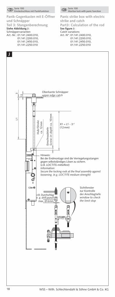
Panik-Gegenkasten mit E-Öffner und Schnäpper Teil 3: StangenberechnungSiehe Abbildung J:SchnäppervariantenArt.-Nr.: 01.141.2400.010,
01.141.2200.010, 01.141.2450.010, 01.141.2250.010
Panic strike box with electric strike and catch Part3: Calculation of the rodSee figure J:Catch variationsArt.-N°: 01.141.2400.010,
01.141.2200.010, 01.141.2450.010, 01.141.2250.010
J
3L1
12
Oberkante Schnäpperupper edge catch
Hub
/Str
oke
ca.
12
mm
Eins
chra
ubti
efe
Scre
w-i
n-de
pth
ca. 1
0 m
m
STOPP!
max. Ø 6 mm
z.B. Durchschlage. g. drift punch
X1 = L1 - 3±1 (12 mm)
Hinweis:Bei der Endmontage sind die Verriegelungs stangen gegen selbstständiges Lösen zu sichern. (z.B. LOCTITE-mittelfest)Information:Secure the locking rods at the final assembly against loosening. (e.g. LOCTITE medium strength)
Sichtfenster zur Kontrolle der Anschlagtiefewindow to check the limit stop
19
Serie 100 Einsteckschloss mit Panikfunktion
Serie 100 Mortise lock with panic function
WSS – Wilh. Schlechtendahl & Söhne GmbH & Co. KG
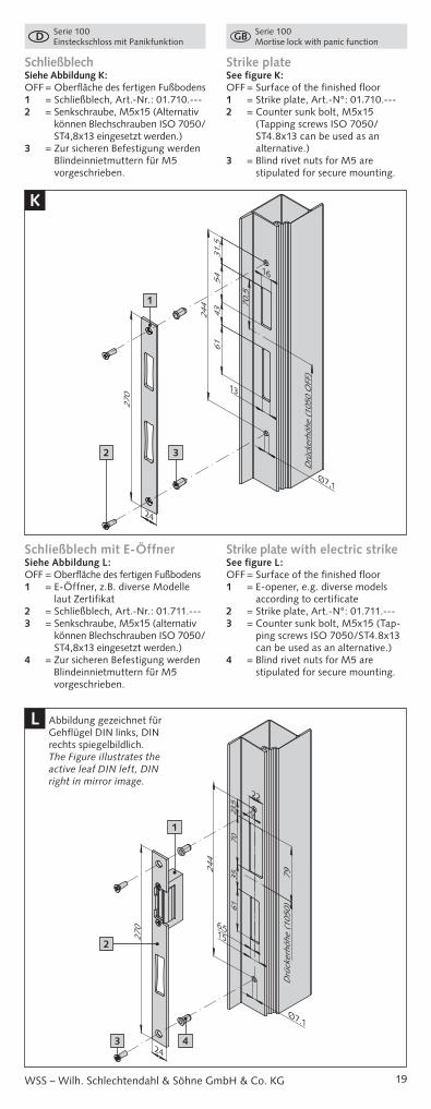
SchließblechSiehe Abbildung K:OFF = Oberfläche des fertigen Fußbodens1 = Schließblech, Art.-Nr.: 01.710.--- 2 = Senkschraube, M5x15 (Alternativ
können Blechschrauben ISO 7050/ST4,8x13 eingesetzt werden.)
3 = Zur sicheren Befestigung werden Blindeinnietmuttern für M5 vorgeschrieben.
Strike plateSee figure K:OFF = Surface of the finished floor1 = Strike plate, Art.-N°: 01.710.--- 2 = Counter sunk bolt, M5x15
(Tapping screws ISO 7050/ST4.8x13 can be used as an alternative.)
3 = Blind rivet nuts for M5 are stipulated for secure mounting.
Schließblech mit E-ÖffnerSiehe Abbildung L:OFF = Oberfläche des fertigen Fußbodens1 = E-Öffner, z.B. diverse Modelle
laut Zertifikat2 = Schließblech, Art.-Nr.: 01.711.---3 = Senkschraube, M5x15 (alternativ
können Blechschrauben ISO 7050/ST4,8x13 eingesetzt werden.)
4 = Zur sicheren Befestigung werden Blindeinnietmuttern für M5 vorgeschrieben.
Strike plate with electric strikeSee figure L:OFF = Surface of the finished floor1 = E-opener, e.g. diverse models
according to certificate2 = Strike plate, Art.-N°: 01.711.---3 = Counter sunk bolt, M5x15 (Tap-
ping screws ISO 7050/ST4.8x13 can be used as an alternative.)
4 = Blind rivet nuts for M5 are stipulated for secure mounting.
5443
270
Drü
cker
höhe
(10
50 O
FF)
61
70,5
31,5
244
16
13
24
Ø7,1
K
1
2 3
6135
70
Drü
cker
höhe
(10
50)
270
22
23.5
79
244
24
15
9
6.5
Ø7.1
L
1
2
3 4
Abbildung gezeichnet für Gehflügel DIN links, DIN rechts spiegelbildlich.The Figure illustrates the active leaf DIN left, DIN right in mirror image.
20
Serie 100 Einsteckschloss mit Panikfunktion
Serie 100 Mortise lock with panic function
WSS – Wilh. Schlechtendahl & Söhne GmbH & Co. KG
Start-up procedure � The recess in the strike plate area must have a depth that does not allow the bolt to reach the hard stop. Possible linear expansion of the door is to be taken into consideration hereby.
� The start-up of the panic lock can be performed with a standard profile cylinder.
� The bolt must be lockable without dragging against the strike box or the strike plate.
� Before start-up, a complete perfor-mance test must be performed based on the “Service and Maintenance” chapter in these instructions.
The result of this test is to be recorded under “Documentation” at the end of these instructions. The ins-tructions are to be handed over to the operator after the performance test.
Service and Maintenance
The following maintenance inter-vals have to be carried out monthly by the operator or an instructed third party and have to be written documented under chapter „Documentation“ of this manual:
� Inspection and operation of the emergency exit device, to ensure that all parts of the device are in proper operation condition.
� An annual force measurement has to be done additionally. The operating forces for the emergency exit device have to be measured with a dynamometer (pressure can etc.) and to be compared with the forces of the initial installation.
� It must be checked and ensured that the latch, the bolt and the lock rods are not blocked.
� The door must be checked for correct resp. and unobstructed opening and should not be warped.
� Check if all screws are tightened resp. all parts of the emergency exit- resp. panic device are firmly installed.
� Based on the provided instruction, the components must be checked for completeness.
� Check if no additional locking devices have been attached subsequently, which may lead to an adverse effect of the panic function (e.g. door stop for stepping).
� Ensure if all locking pieces lock completely. The contact surfaces of the latch for the strike plates and the locking bars inside the locking parts must be well greased.
Inbetriebnahme � Die Ausnehmung im Bereich des Schließ bleches muss so tief sein, dass der Riegel nicht auf Block fahren kann. Hierbei sind auch eventuelle Längen ausdehnungen der Tür zu berücksichtigen.
� Die Inbetriebnahme des Panikschlosses kann mit einem handelsüblichen Profilzylinder erfolgen.
� Der Riegel muss, ohne am Gegenkasten oder am Schließblech zu schleifen, einschließen können.
� Vor der Inbetriebnahme muss eine vollständige Funktionskontrolle anhand Kapitel „Wartung und Instandhaltung“ dieser Anleitung durchgeführt werden.
Das Ergebnis dieser Prüfung ist unter „Dokumentation“ am Schluss dieser Anleitung schriftlich festzuhalten. Die Anleitung ist nach der Funktionskontrolle dem Betreiber zu übergeben.
Wartung und Instandhaltung
Vom Betreiber oder einem beauf-tragten Dritten sind folgende laufende Wartungs arbeiten in Abständen von nicht mehr als einem Monat durchzu-führen und schriftlich unter „Dokumen-tation“ am Schluss dieser Anleitung zu dokumentieren:
� Inspektion und Betätigung des Not-ausgangs- bzw. Panikverschlusses, um sicherzustellen, dass sämtliche Teile des Verschlusses in einem ein-wandfreien Betriebszustand sind.
� Zusätzlich ist mindestens 1x im Jahr eine Kräftemessung vorzunehmen. Mit einem Kraftmesser (Druckdose etc.) sind die Betätigungskräfte zum Freigeben des Fluchttürverschlusses zu messen und aufzuzeichnen.
� Es ist zu prüfen bzw. sicherzustellen, dass die Falle, der Riegel und die Ver-riegelungsstangen nicht blockiert sind.
� Die Tür ist auf korrekte bzw. leichte und ungehinderte Öffnung zu prüfen und darf keinen Verzug aufweisen.
� Prüfen, ob sämtliche Schrauben fest angezogen sind, bzw. alle Teile des Notausgangs- bzw. Panikverschlusses fest montiert sind.
� Anhand der vorliegenden Anleitung sind die Beschlagskomponenten auf Vollständigkeit zu prüfen.
� Prüfen, ob nachträglich keine zusätzlichen Verriegelungsvorrich-tungen angebracht wurden, die zur Beeinträchtigung der Panikfunktion führen könnten (z.B. Türfeststeller zum Treten ....).
� Vergewissern, dass sämtliche Sperr-stücke vollständig einschließen und die Kontaktflächen der Falle zum Schließblech und die Verriegelungs-stangen in den Sperrteilen gut gefettet sind
21
Serie 100 Einsteckschloss mit Panikfunktion
Serie 100 Mortise lock with panic function
WSS – Wilh. Schlechtendahl & Söhne GmbH & Co. KG
Entsorgung
Handeln Sie im Interesse der Umwelt!Alle Elektro- und Elektronik-geräte sind getrennt vom allgemeinen Hausmüll über
die dafür staatlich vorgesehenen Stellen zu entsorgen. Wenn das Symbol einer durchgestrichenen Abfalltonne auf einem Produkt angebracht ist, unterliegt dieses Produkt der europäischen Richt-linie 2002/96/EC.
Ausführliche Informationen zur Ent-sorgung Ihrer Altgeräte erhalten Sie bei Ihrer Kommune, ihrem Müllentsor-gungsdienst oder dem Fachhändler, bei dem Sie das Produkt erworben haben.
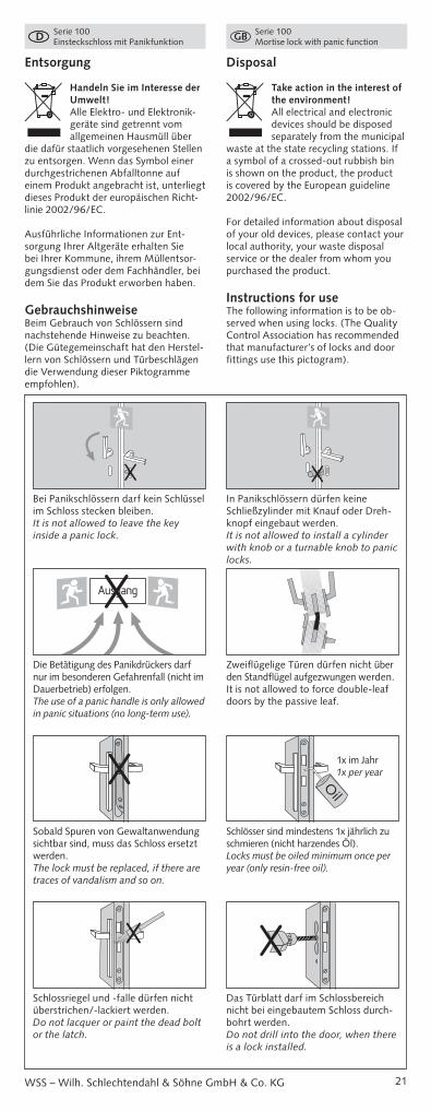
GebrauchshinweiseBeim Gebrauch von Schlössern sind nachstehende Hinweise zu beachten. (Die Gütegemeinschaft hat den Herstel-lern von Schlössern und Türbeschlägen die Verwendung dieser Piktogramme empfohlen).
Disposal
Take action in the interest of the environment!All electrical and electronic devices should be disposed separately from the municipal
waste at the state recycling stations. If a symbol of a crossed-out rubbish bin is shown on the product, the product is covered by the European guideline 2002/96/EC.
For detailed information about disposal of your old devices, please contact your local authority, your waste disposal service or the dealer from whom you purchased the product.
Instructions for useThe following information is to be ob-served when using locks. (The Quality Control Association has recommended that manufacturer’s of locks and door fittings use this pictogram).
In Panikschlössern dürfen keine Schließzylinder mit Knauf oder Dreh-knopf eingebaut werden.It is not allowed to install a cylinder with knob or a turnable knob to panic locks.
Bei Panikschlössern darf kein Schlüssel im Schloss stecken bleiben.It is not allowed to leave the key inside a panic lock.
X X
Zweiflügelige Türen dürfen nicht über den Standflügel aufgezwungen werden.It is not allowed to force double-leaf doors by the passive leaf.
Die Betätigung des Panikdrückers darf nur im besonderen Gefahrenfall (nicht im Dauerbetrieb) erfolgen.The use of a panic handle is only allowed in panic situations (no long-term use).
AusgangX
Schlösser sind mindestens 1x jährlich zu schmieren (nicht harzendes Öl).Locks must be oiled minimum once per year (only resin-free oil).
Sobald Spuren von Gewalt anwendung sichtbar sind, muss das Schloss ersetzt werden.The lock must be replaced, if there are traces of vandalism and so on.
X 1 malim Jahr
Oil
Das Türblatt darf im Schlossbereich nicht bei eingebautem Schloss durch-bohrt werden.Do not drill into the door, when there is a lock installed.
Schlossriegel und -falle dürfen nicht überstrichen/-lackiert werden.Do not lacquer or paint the dead bolt or the latch.
X X
1x im Jahr1x per year

22
Serie 100 Einsteckschloss mit Panikfunktion
Serie 100 Mortise lock with panic function
WSS – Wilh. Schlechtendahl & Söhne GmbH & Co. KG
DokumentationDocumentation
Übergabeprotokoll der Funktionskontrolle zur Erstinbetriebnahme Completion certificate of the function control for initial operation
Türnummer Door Number
Prüfer Controller
Datum Date
Unterschrift Signature
Dokumentation der Wartung Documentation of Service
Türnummer Door Number
Prüfer Controller
Datum Date
Unterschrift Signature
1
2
3
4
5
6
7
8
9
10
11
12
Der Drücker darf nur im normalen Drehsinn belastet werden. In Betäti-gungsrichtung darf auf den Drücker maximal nur eine Kraft von 150 N aufgebracht werden.The handle must only be used with normal power. The power to the handle has to be max. 150 Newton.
Drücker und Schlüssel dürfen nicht gleichzeitig betätigt werden.Handle and key must not be used at the same time.
Der Drückerstift darf nicht mit Gewalt durch die Schlossnuss geschlagen werden.The square spindle must not be hit into the follower.
Der Schlossriegel darf nicht bei offe-ner Tür vorgeschlossen sein.The dead bolt must not be locked when the door is open.
X
X
max.150 N
XXX
max. 150 N


WILH. SCHLECHTENDAHL& SÖHNE GMBH & CO. KG
Hauptstraße 18-3242579 Heiligenhaus
Postfach 10 05 52/6242570 Heiligenhaus
Tel.: +49 (0) 20 56/17-0Fax: +49 (0) 20 56/51 42
Web: www.wss.deE-Mail: [email protected]
ma_
K02
0006
5_Pa
nik-
Roh
rrah
men
schl
oss_
Serie
100_
DE_
GB
© 1
2/20
15 •
Wilh
. Sch
lech
tend
ahl &
Söh
ne G
mbH
& C
o. K
G