Ersatzteil Sonde + Adapter - ITALIA - KESSEL · tème de protection anti-retour. ①②③④...
20
MONTAGEHINWEIS Ersatzteil Sonde + Adapter Für alle Staufix Premium Systeme und Ecolift für folgende Schaltgeräte: 80073, 28073, 80071, 28071, 21071 und Ersatz Sonden 80085, 80086, 80087, 80088, 680117, 680455 Sach-Nr. 010-880 Stand 2016/06 Page 1 Page 4 Page 7 Pagina 10 Pagina 13 Strona 16 Beachten Sie die Sicherheitshinweise und weitere Beschreibung in den zugehörigen EBAs. • Für den Ersatz der Pumpensonde ist der rote Adapter (der Rote Adapter entspricht der alten Sonde 80086!) richtig aufzustecken (Bajonettverschluss, 1/4 Umdrehung gegen den Uhrzeigersinn) und den roten Aufkleber am Sondenkabel in Steckernähe anbringen – siehe Bild 1-3. • Für den Ersatz der Motorsonde ist der schwarze Adapter richtig auf- zustecken – siehe Bild 4-6. • Diese Erhöhungen verhindern einen Fehlverbau und müssen beim Verschrauben am Rück- stausystem nach oben zeigen. ① ② ③ ④ Lieferumfang Wenn bauseits erforderlich (z. B. Kabelleerrohr, Länge ändern, etc.) Schwarze Verschraubung abschrauben Stecker abziehen Rückstände entfernen Kabel bis Anschlag einführen Montagehinweis Adapter: Alte Kontaktstellen entfer- nen und neu abisolieren Gültig ab Baujahr 01/2011 ⑤ ⑥ Fortsetzung Seite 2 D GB F I NL PL Drehmoment siehe Seite 19
Transcript of Ersatzteil Sonde + Adapter - ITALIA - KESSEL · tème de protection anti-retour. ①②③④...
MONTAGEHINWEIS
Ersatzteil Sonde + AdapterFür alle Staufix Premium Systeme und Ecolift für folgende Schaltgeräte: 80073, 28073, 80071, 28071, 21071 und Ersatz Sonden 80085, 80086, 80087, 80088,680117, 680455
Sach-Nr. 010-880 Stand 2016/06
Page 1
Page 4
Page 7
Pagina 10
Pagina 13
Strona 16
Beachten Sie die Sicherheitshinweise und weitere Beschreibung in den zugehörigen EBAs.
• Für den Ersatz der Pumpensonde ist der rote Adapter (der RoteAdapter entspricht der alten Sonde 80086!) richtig aufzustecken(Bajonettverschluss, 1/4 Umdrehung gegen den Uhrzeigersinn) undden roten Aufkleber am Sondenkabel in Steckernähe anbringen –siehe Bild 1-3.
• Für den Ersatz der Motorsonde ist der schwarze Adapter richtig auf-zustecken – siehe Bild 4-6.
• Diese Erhöhungen verhinderneinen Fehlverbau und müssenbeim Verschrauben am Rück-stausystem nach oben zeigen.
① ② ③ ④ Lieferumfang
Wenn bauseits erforderlich (z. B. Kabelleerrohr, Länge ändern, etc.)
Schwarze Verschraubungabschrauben
Stecker abziehen Rückstände entfernen
Kabel bis Anschlag einführen
Montagehinweis Adapter:
Alte Kontaktstellen entfer-nen und neu abisolieren
Gültig ab Baujahr 01/2011
⑤ ⑥
Fortsetzung Seite 2
DGBFI
NLPL
Drehmoment siehe Seite 19
2
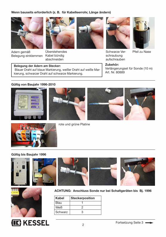
Kabel SteckerpositionBlau 1
Weiß 2
Schwarz 3
Gültig bis Baujahr 1996
Belegung der Adern am Stecker:Blauer Draht auf blaue Markierung, weißer Draht auf weiße Mar-
kierung, schwarzer Draht auf schwarze Markierung.
Gültig von Baujahr 1996-2010
Wenn bauseits erforderlich (z. B. für Kabelleerrohr, Länge ändern)
Adern gemäß Belegung einklemmen
ÜberstehendesKabel bündigabschneiden
Schwarze Ver-schraubung aufschrauben
Zubehör:Verlängerungset für Sonde (10 m)Art. Nr. 80889
ACHTUNG: Anschluss Sonde nur bei Schaltgeräten bis Bj. 1996
rote und grüne Platine
Pfeil zu Nase
Fortsetzung Seite 3
3
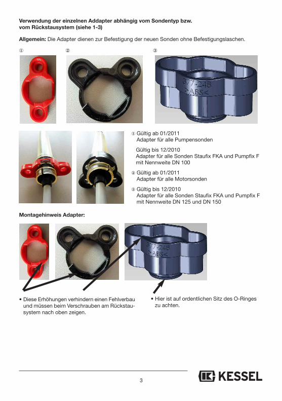
① Gültig ab 01/2011Adapter für alle Pumpensonden
Gültig bis 12/2010Adapter für alle Sonden Staufix FKA und Pumpfix F mit Nennweite DN 100
② Gültig ab 01/2011Adapter für alle Motorsonden
③ Gültig bis 12/2010Adapter für alle Sonden Staufix FKA und Pumpfix F mit Nennweite DN 125 und DN 150
• Diese Erhöhungen verhindern einen Fehlverbauund müssen beim Verschrauben am Rückstau-system nach oben zeigen.
① ② ③
Montagehinweis Adapter:
Allgemein: Die Adapter dienen zur Befestigung der neuen Sonden ohne Befestigungslaschen.
• Hier ist auf ordentlichen Sitz des O-Ringeszu achten.
Verwendung der einzelnen Addapter abhängig vom Sondentyp bzw. vom Rückstausystem (siehe 1-3)
4
INSTALLATION INSTRUCTION
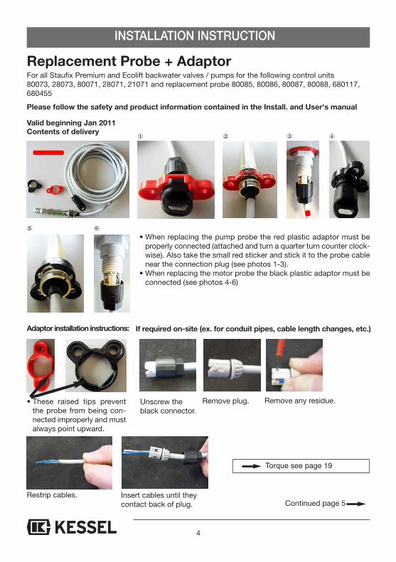
Replacement Probe + Adaptor For all Staufix Premium and Ecolift backwater valves / pumps for the following control units80073, 28073, 80071, 28071, 21071 and replacement probe 80085, 80086, 80087, 80088, 680117,680455
Please follow the safety and product information contained in the Install. and User's manual
• When replacing the pump probe the red plastic adaptor must beproperly connected (attached and turn a quarter turn counter clock-wise). Also take the small red sticker and stick it to the probe cablenear the connection plug (see photos 1-3).
• When replacing the motor probe the black plastic adaptor must beconnected (see photos 4-6)
• These raised tips preventthe probe from being con-nected improperly and mustalways point upward.
① ② ③ ④ Contents of delivery
If required on-site (ex. for conduit pipes, cable length changes, etc.)
Unscrew theblack connector.
Remove plug. Remove any residue.
Insert cables until theycontact back of plug.
Adaptor installation instructions:
Restrip cables.
Valid beginning Jan 2011
⑤ ⑥
Continued page 5
Torque see page 19

5
Cable Jackblue 1
white 2
black 3
Valid up to 1996
Cable description:Blue cable on blue mark, white cable on white mark, black cableon black mark
Valid from 1996 to 2010
If required on-site (for example for conduit pipes, cable length changes, etc.)
Connect cables to proper position (seedescription to the right)
Cut off any cableportions which aresticking out
Re-screw theblack connectorto the plug
Accessories: 10 meter probe cable extension -Article Number 80889
Attention: connection of probe on for control units up to 1996
Red and green circuit board
Arrow on plugshould matchtriangular tip onthreads.
Continued page 6
6
① For models January 2011 and newerAdaptor for all pump optical sensors
For models up to December 2010Adaptor for all Staufix FKA and Pumpfix F optical sensors for DN 100 (OD 110 mm) models
② For models January 2011and newerAdaptor for all motor optical sensors
③ For models up to December 2010Adaptor for all Staufix FKA and Pumpfix F opticalsensors for DN 125 (OD 125 mm) and DN 150 (OD160 mm) models.Must be used in combination with the red adaptor(adaptor ① is inserted into the top of adaptor ③).
• The raised edge on the adaptors are to assure the adaptor ist installed properlyand should always be pointing up.
① ② ③
Installation note adaptor:
General: The adaptors are used to fasten the new Probes without mounting brackets.
Use each adaptor depending on probe type and the backwater system (see 1-3)
7
AVIS DE MONTAGE
Pièce de rechange sonde + adaptateurApproprié à tous les systèmes Staufix Premium et Ecolift pour les boîtiers de commande suivants :80073, 28073, 80071, 28071, 21071 et les sondes de rechange 80085, 80086, 80087, 80088,680117, 680455
Observez les consignes de sécurité et autres descriptions données dans les instructions demontage respectives.
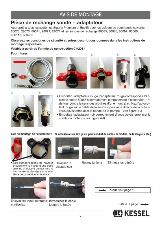
• Emboîtez l'adaptateur rouge (l'adaptateur rouge correspond à l'an-cienne sonde 80086 !) correctement (emboîtement à baïonnette, 1/4de tour contre le sens des aiguilles d'une montre) et fixez l'autocol-lant rouge sur le câble de la sonde à proximité directe de la fiche sivous devez remplacer la sonde de la pompe – voir figure 1-3
• Emboîtez l'adaptateur noir correctement si vous devez remplacer lasonde du moteur – voir figure 4-6.
• Ces compensations de hauteurpréviennent le risque d'une poseerronée et doivent pointer vers lehaut après le vissage sur le sys-tème de protection anti-retour.
① ② ③ ④ Fournitures
Si nécessaire sur site (p. ex. pour conduit de câbles, la modific. de la longueur etc.)
Dévissez le vissage noir
Retirez la fiche Éliminez les dépôts
Introduisez le câble jusqu'à la butée
Avis de montage de l'adaptateur :
Enlevez les vieux contactset réisolez
Valable à partir de l'année de construction 01/2011
⑤ ⑥
Suite à la page 8
Torque voir page 19
8
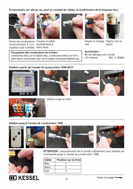
Câble Position sur la fiche Bleu 1
Blanc 2
Noir 3
Valable jusqu'à l'année de construction 1996
Occupation des conducteurs de la fiche : conducteur bleu sur le repère bleu, conducteur blanc sur le re-père blanc, conducteur noir sur le repère noirwarze Markierung.
Valable à partir de l'année de construction 1996-2010
Si nécessaire sur site (p. ex. pour un conduit de câbles, la modification de la longueur etc.)
Serrez les conducteursconformément à l'oc-cupation (voir à droite)
Coupez le câbleexcédentaire àfranc-bord
Vissez le vissagenoir
Accessoire : kit de rallonge pour sonde (10 mètres) Réf. n° 80889
ATTENTION : raccordement de la sonde uniquement pour boîtiers decommande jusqu'à l'année de construction 1996.
platine rouge et verte
Flèche vers letenon
Suite à la page 9
9
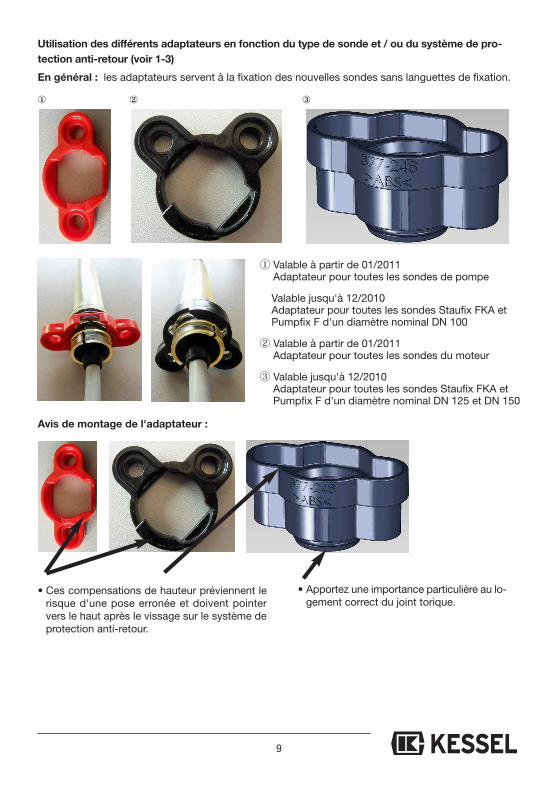
① Valable à partir de 01/2011Adaptateur pour toutes les sondes de pompe
Valable jusqu'à 12/2010Adaptateur pour toutes les sondes Staufix FKA etPumpfix F d'un diamètre nominal DN 100
② Valable à partir de 01/2011Adaptateur pour toutes les sondes du moteur
③ Valable jusqu'à 12/2010Adaptateur pour toutes les sondes Staufix FKA etPumpfix F d'un diamètre nominal DN 125 et DN 150
• Ces compensations de hauteur préviennent lerisque d'une pose erronée et doivent pointervers le haut après le vissage sur le système deprotection anti-retour.
① ② ③
Avis de montage de l'adaptateur :
En général : les adaptateurs servent à la fixation des nouvelles sondes sans languettes de fixation.
• Apportez une importance particulière au lo-gement correct du joint torique.
Utilisation des différents adaptateurs en fonction du type de sonde et / ou du système de pro-
tection anti-retour (voir 1-3)

10
ISTRUZIONI PER IL MONTAGGIO
Pezzo di ricambio sonda + adattatore Per tutti i sistemi Staufix Premium ed Ecolift per le seguenti centraline: 80073, 28073, 80071, 28071, 21071 e sonde di ricambio 80085, 80086, 80087, 80088, 680117,680455
Rispettare le avvertenze sulla sicurezza e l’ulteriore descrizione nelle relative istruzioni per ilmontaggio. Valido dall’anno di costruzione 01/2011
• Per la sostituzione della sonda della pompa applicare correttamentel’adattatore rosso (che corrisponde alla vecchia sonda 80086!) (chiu-sura a baionetta, ¼ di giro in senso antiorario) e l’adesivo rosso sulcavo della sonda vicino alla spina – vedi illustrazione 1-3
• Per la sostituzione della sonda del motore applicare correttamentel’adattatore nero – vedi illustrazione 4-6
• Questi rialzi impediscono unmontaggio errato e durantel’avvitamento sul sistema an-tiriflusso devono essere ri-volti verso l’alto.
① ② ③ ④ Volume della fornitura
Se necessario a cura del committente (p.es. per tubo vuoto percavi, modificare la lunghezza, ecc.)
Svitare il raccordo a vitenero
Staccare la spina Eliminare i residui
Introdurre il cavo finoall’arresto
Istruzioni per il montaggiodell’adattatore:
Eliminare i punti di contattovecchi e rispelare
⑤ ⑥
Continua a pagina 11
Coppia vedere a pagina 19
11
Cavo Posizione spinablu 1bianco 2nero 3
Valido dall’anno di costruzione 1996
Occupazione dei fili sulla spina: filo blu sul contrassegno blu, filo bianco sul contrassegno bi-anco, filo nero sul contrassegno nero.
Valido dall’anno di costruzione 1996-2010
Se necessario a cura del committente (p.es. per tubo vuoto per cavi, modificare la lunghezza)
Collegare i fili se-condo l’occupazione(vedi destra)
Tagliare a paro ilcavo sporgente
Avvitare il rac-cordo a vite nero
Accessori: set di prolungamento per sonda(10 m) n. art. 80889
ATTENZIONE : collegamento sonda solo per centraline fino all’anno di costruzione 1996
scheda rossa e verde
Freccia verso ilnasello
Continua a pagina 12
12
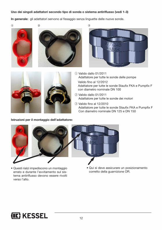
① Valido dallo 01/2011Adattatore per tutte le sonde delle pompe
Valido fino al 12/2012Adattatore per tutte le sonde Staufix FKA e Pumpfix Fcon diametro nominale DN 100
② Valido dallo 01/2011Adattatore per tutte le sonde dei motori
③ Valido fino al 12/2010Adattatore per tutte le sonde Staufix FKA e Pumpfix F Con diametro nominale DN 125 e DN 150
• Questi rialzi impediscono un montaggioerrato e durante l’avvitamento sul sis-tema antiriflusso devono essere rivoltiverso l’alto.
① ② ③
Istruzioni per il montaggio dell’adattatore:
In generale: gli adattatori servono al fissaggio senza linguette delle nuove sonde.
• Qui si deve assicurare un posizionamentocorretto della guarnizione OR.
Uso dei singoli adattatori secondo tipo di sonda o sistema antiriflusso (vedi 1-3)
13
MONTAGE-INSTRUCTIE
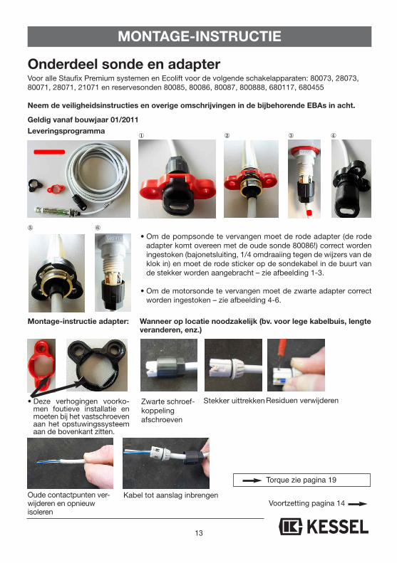
Onderdeel sonde en adapterVoor alle Staufix Premium systemen en Ecolift voor de volgende schakelapparaten: 80073, 28073,80071, 28071, 21071 en reservesonden 80085, 80086, 80087, 800888, 680117, 680455
Neem de veiligheidsinstructies en overige omschrijvingen in de bijbehorende EBAs in acht.
• Om de pompsonde te vervangen moet de rode adapter (de rodeadapter komt overeen met de oude sonde 80086!) correct wordeningestoken (bajonetsluiting, 1/4 omdraaiing tegen de wijzers van deklok in) en moet de rode sticker op de sondekabel in de buurt vande stekker worden aangebracht – zie afbeelding 1-3.
• Om de motorsonde te vervangen moet de zwarte adapter correctworden ingestoken – zie afbeelding 4-6.
• Deze verhogingen voorko-men foutieve installatie enmoeten bij het vastschroevenaan het opstuwingssysteemaan de bovenkant zitten.
① ② ③ ④ Leveringsprogramma
Wanneer op locatie noodzakelijk (bv. voor lege kabelbuis, lengteveranderen, enz.)
Zwarte schroef-koppeling afschroeven
Stekker uittrekken Residuen verwijderen
Kabel tot aanslag inbrengen
Montage-instructie adapter:
Oude contactpunten ver-wijderen en opnieuw isoleren
Geldig vanaf bouwjaar 01/2011
⑤ ⑥
Voortzetting pagina 14
Torque zie pagina 19
14
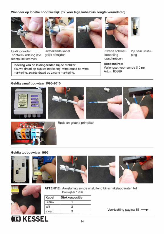
Kabel StekkerpositieBlauw 1Wit 2Zwart 3
Geldig tot bouwjaar 1996
Indeling van de leidingdraden bij de stekker:blauwe draad op blauwe markering, witte draad op witte markering, zwarte draad op zwarte markering.
Geldig vanaf bouwjaar 1996-2010
Wanneer op locatie noodzakelijk (bv. voor lege kabelbuis, lengte veranderen)
Leidingdradenconform indeling (zie
rechts) inklemmen
Uitstekende kabelgelijk afsnijden
Zwarte schroef-koppeling opschroeven
Accessoires:Verlengset voor sonde (10 m)Art.nr. 80889
ATTENTIE: Aansluiting sonde uitsluitend bij schakelapparaten totbouwjaar 1996
Rode en groene printplaat
Pijl naar uitstul-ping
Voortzetting pagina 15

15
① Geldig vanaf 01/2011Adapter voor alle pompsonden
Geldig tot 12/2010Adapter voor alle sonden Staufix FKA en Pumpfix F met nominale doorlaat DN 100
② Geldig vanaf 01/2011Adapter voor alle motorsonden
③ Geldig tot 12/2010Adapter voor alle sonden Staufix FKA en Pumpfix F met nominale doorlaat DN 125 en DN 150
• Deze verhogingen voorkomen foutieveinstallatie en moeten bij het vastschroe-ven aan het opstuwingssysteem aan debovenkant zitten.
① ② ③
Montage adapter:
Algemeen: De adapters dienen ter bevestiging van de nieuwe sonden zonder bevestigingsstrips.
• Hier moet op goed zittenvan de O-ring worden gelet
Gebruik van de afzonderlijke adapters afhankelijk van het sondetype resp. van het opstuwingsys-teem (zie 1-3)
16
WSkazóWka mOntażOWa
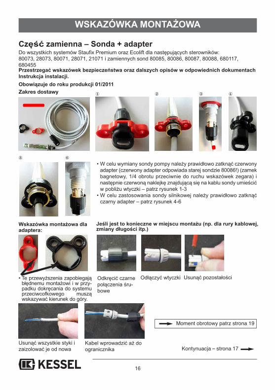
Część zamienna – Sonda + adapterDo wszystkich systemów Staufix Premium oraz Ecolift dla następujących sterowników: 80073, 28073, 80071, 28071, 21071 i zamiennych sond 80085, 80086, 80087, 80088, 680117,680455Przestrzegać wskazówek bezpieczeństwa oraz dalszych opisów w odpowiednich dokumentachInstrukcja instalacji.
• W celu wymiany sondy pompy należy prawidłowo zatknąć czerwonyadapter (czerwony adapter odpowiada starej sondzie 80086!) (zamekbagnetowy, 1/4 obrotu przeciwnie do ruchu wskazówek zegara) inastępnie czerwoną naklejkę znajdującą się na kablu sondy umieścićw pobliżu wtyczki – patrz rysunek 1-3
• W celu zastosowania sondy silnikowej należy prawidłowo zatknąćczarny adapter – patrz rysunek 4-6
• Te przewyższenia zapobiegająbłędnemu montażowi i w przy-padku dokręcania do systemuprzeciwcofkowego musząwskazywać kierunek do góry.
① ② ③ ④
Jeśli jest to konieczne w miejscu montażu (np. dla rury kablowej,zmiany długości itp.)
Odkręcić czarnepołączenia śru-bowe
Odłączyć wtyczki Usunąć pozostałości
Kabel wprowadzić aż do ogranicznika
Wskazówka montażowa dlaadaptera:
Usunąć wszystkie styki izaizolować je od nowa
Obowiązuje do roku produkcji 01/2011
⑤ ⑥
Kontynuacja – strona 17
Zakres dostawy
Moment obrotowy patrz strona 19

17
Kabel Pozycja wtyczkiNiebieski 1Biały 2Czarny 3
Obowiązuje do roku produkcji 1996
Obłożenie żył na wtyczce: niebieski przewód na niebieskie zaznaczenie, biały przewód nabiałe zaznaczenie, czarny przewód na czarne zaznaczenie.
Obowiązuje od roku produkcji 1996-2010
Jeśli jest to konieczne w miejscu montażu (np. dla rury kablowej, zmiany długości
Żyły wpiąć zgodnie zich obłożeniem (patrzpo prawej stronie)
Wystający kabelrówno odciąć
Nakręcić czarnepołączenie śrubowe
Akcesoria: zestaw przedłużania dla sondy (10 m) Nr art. 80889
UWAGA! Przyłączenie sondy tylko w sterownikach do roku produkcji 1996
czerwona i zielona płytka
Strzałka donoska
Kontynuacja – strona 18
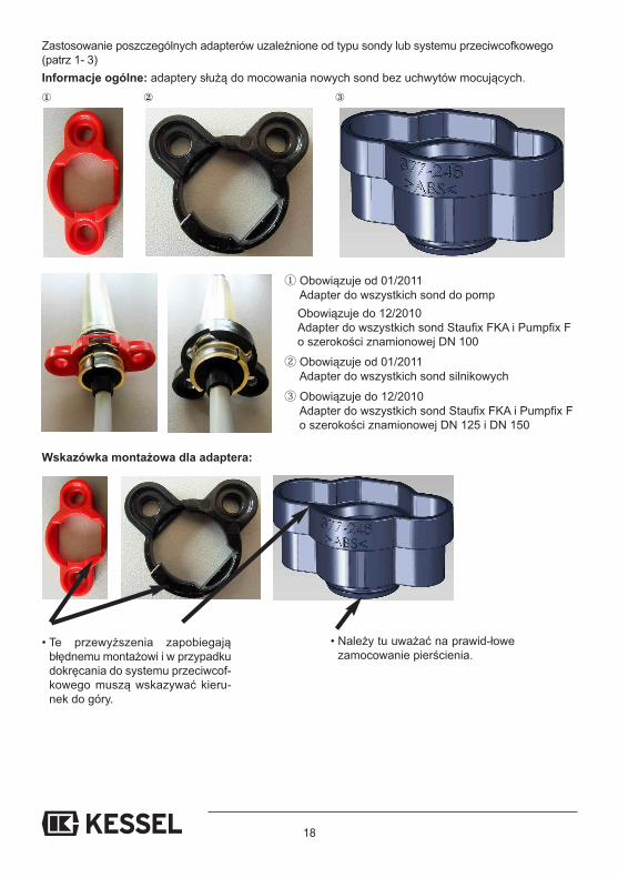
① Obowiązuje od 01/2011Adapter do wszystkich sond do pompObowiązuje do 12/2010Adapter do wszystkich sond Staufix FKA i Pumpfix F o szerokości znamionowej DN 100
② Obowiązuje od 01/2011Adapter do wszystkich sond silnikowych
③ Obowiązuje do 12/2010Adapter do wszystkich sond Staufix FKA i Pumpfix F o szerokości znamionowej DN 125 i DN 150
• Te przewyższenia zapobiegająbłędnemu montażowi i w przypadkudokręcania do systemu przeciwcof-kowego muszą wskazywać kieru-nek do góry.
① ② ③
Wskazówka montażowa dla adaptera:
Informacje ogólne: adaptery służą do mocowania nowych sond bez uchwytów mocujących.
• Należy tu uważać na prawid-łowezamocowanie pierścienia.
Zastosowanie poszczególnych adapterów uzależnione od typu sondy lub systemu przeciwcofkowego(patrz 1- 3)
18
19
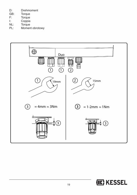
19mm 15mm
1 1 2
2
= 1-2mm 1Nm= 4mm 3Nm
3
333 ≈ ≈
1
3
Duo
D: DrehmomentGB: TorqueF: TorqueI: CoppiaNL: TorquePL: Moment obrotowy

Führend in Entwässerung
Privater Wohnungsbauohne Kanalanbindung
1 2 3 4 5
Öffentlicher Bauz.B. Freizeitanlagen
6 4
Privater WohnungsbauEin- und Mehrfamilienhaus
Gewerblicher Bauz.B. Tankstellen
Gewerblicher Bauz.B. Hotel
Öffentlicher Bauz.B. Krankenhaus
4 5
Gewerblicher Bauz.B. Industriebau
1 Rückstauverschlüsse 2 Rückstauhebeanlagen 3 Hebeanlagen
4 Abläufe / Rinnen 5 Abscheider 6 Kleinkläranlagen
1 2 3 4 5
1 2 3 4 5
1 2 3 4
2 3 5
![Master [120] : ingénieur civil électromécanicien...Le programme d'ingénieur civil électromécanicien conduit ainsi à la formation d'ingénieurs bien armés pour suivre l'évolution](https://static.fdokument.com/doc/165x107/5ff01f4b915a0c294031a6bc/master-120-ingnieur-civil-lectromcanicien-le-programme-dingnieur.jpg)