
ETH2DALI - Osram€¦ · OSRAM GmbH Customer Service Ursula-Platz 1 50668 Cologne Germany +49 (221)...
48
ETH2DALI System Manual/Installationsanleitung
Transcript of ETH2DALI - Osram€¦ · OSRAM GmbH Customer Service Ursula-Platz 1 50668 Cologne Germany +49 (221)...
ETH2DALISystem Manual/Installationsanleitung
ETH2DALI Setup Manual (original issue) ETH2DALI Installationsanleitung (Originalversion)
Edition/Ausgabe: 12.11.15 [EN_DE_ETH2DALI_Setup_v1p2] Published by/Herausgegeben von:
OSRAM GmbH BU Lighting Solutions Karl Schurz-Strasse 38 Paderborn, Germany ©2015, OSRAM GmbH All rights reserved/Alle Rechte vorbehalten Comments to/Kommentare an: [email protected]
Subject to modification without prior notice. Typographical and other errors do not justify any claim for damages. All dimensions should be verified using an actual part.
Except for internal use, relinquishment of the instructions to a third party, duplication in any type or form - also extracts - as well as exploitation and/or communication of the contents is not permitted.
Alle Änderungen vorbehalten. Rechtschreibfehler oder andere Fehler rechtfertigen keinen Anspruch bei Schäden. Alle Maße sollten an einem realen Gerät überprüft werden.
Außer für interne Verwendung ist die Überlassung dieser Anleitung an Dritte, die gesamte oder auszugsweise Veröffentlichung, Verwertung oder Mitteilung in jeglicher Art und Form sind nicht gestattet.

Table of Contents
English ...................................................................................................61 Security instructions .................................................................................................71.1 Symbols ...............................................................................................................71.2 Instructions ..........................................................................................................7
2 General remarks .......................................................................................................72.1 Transport ..............................................................................................................72.2 Unpacking and delivery content ...........................................................................72.3 Warranty regulations .............................................................................................72.4 Disposal ...............................................................................................................72.5 Maintenance and Repair.......................................................................................82.6 Support ................................................................................................................8
3 Technical specifications ...........................................................................................83.1 Certifications ........................................................................................................83.2 General specifications ..........................................................................................83.3 Interface specifications .........................................................................................9
4 Device description....................................................................................................104.1 Functions and features .........................................................................................104.2 Delivery content....................................................................................................10
5 Installation ................................................................................................................105.1 Installation conditions ...........................................................................................115.2 DALI line configuration ..........................................................................................115.3 Connectors and interfaces ...................................................................................115.4 Connector details .................................................................................................125.5 LED indicators ......................................................................................................125.6 Cursor buttons .....................................................................................................125.7 micro SDcard .......................................................................................................135.8 Ethernet connection .............................................................................................13
6 Control over serial interface .....................................................................................136.1 Interface specifications .........................................................................................136.2 Commands ..........................................................................................................13
7 Configuration ............................................................................................................147.1 Online configuration..............................................................................................147.2 Standalone configuration with a web browser ....................................................177.3 Display messages and standalone setup ..............................................................187.4 Standalone configuration with buttons and display ..............................................207.5 System setup .......................................................................................................207.6 DALI setup ...........................................................................................................21
8 Test mode ...............................................................................................................228.1 DALI test buttons ................................................................................................228.2 Running the DALI test ..........................................................................................228.3 Device Override ....................................................................................................23
9 Firmware update .....................................................................................................23
10 Action Pad and Mobile Action Pad ..........................................................................23

11 Problem analysis ......................................................................................................2411.1 Error display messages ........................................................................................24
Deutsch ...............................................................................................2512 Sicherheitshinweise..................................................................................................2612.1 Symbole ...............................................................................................................2612.2 Hinweise ..............................................................................................................26
13 Allgemeine Hinweise ................................................................................................2613.1 Transport ..............................................................................................................2613.2 Entpacken und Lieferumfang ................................................................................2613.3 Garantiebestimmungen ........................................................................................2613.4 Entsorgung ..........................................................................................................2713.5 Reparatur und Wartung ........................................................................................2713.6 Technischer Support ............................................................................................27
14 Technische Daten ....................................................................................................2714.1 Zertifizierungen .....................................................................................................2714.2 Allgemeine Daten .................................................................................................2714.3 Schnittstellen ........................................................................................................28
15 Gerätebeschreibung .................................................................................................2915.1 Funktionen und Eigenschaften .............................................................................2915.2 Lieferumfang ........................................................................................................29
16 Installation ................................................................................................................3016.1 Montagebedingungen ..........................................................................................3016.2 Anschlüsse und Schnittstellen ..............................................................................3016.3 Anschlussdetails...................................................................................................3116.4 LED-Anzeigen ......................................................................................................3116.5 Cursor-Taster .......................................................................................................3216.6 micro SD-Karte ....................................................................................................3216.7 Ethernet-Anschluss ..............................................................................................32
17 Steuerung über serielle Schnittstelle ........................................................................3217.1 Schnittstellen-Spezifikationen ...............................................................................3217.2 Kommandos ........................................................................................................33
18 Konfiguration ............................................................................................................3318.1 Online-Konfiguration .............................................................................................3318.2 Standalone-Konfiguration mit einem Webbrowser ...............................................3618.3 Displayanzeigen und Standalone-Setup ...............................................................3818.4 Standalone-Konfiguration mit Tastern und Display ...............................................3918.5 Device Setup ........................................................................................................3918.6 DALI-Setup ..........................................................................................................40
19 Test-Modus .............................................................................................................4119.1 DALI-Tests ..........................................................................................................4119.2 Ausführen des DALI-Tests ....................................................................................4219.3 Device Override ....................................................................................................42
20 Firmware-Update .....................................................................................................43
21 Action Pad und Mobile Action Pad ..........................................................................43

22 Problemanalysen ......................................................................................................4322.1 Fehleranzeigen auf Display ...................................................................................43
Appendix .............................................................................................4523 Dimensions/Abmessungen ......................................................................................46

English

7
ETH2DALI: Security instructions - Symbols
1 Security instructionsPlease read the security instructions, provided in a separated manual, carefully. Make sure that the given environmental conditions, mounting and installation prerequisites are met. This manual should be kept at a safe place and in reach of the installation.
1.1 Symbols
!The exclamation mark warns about possible danger for persons or possible damage of the device.
iThe information symbol gives general hints and informs about handling and procedures for use of the device.
1.2 Instructions
!Connect the DALI lines only when the ETH2DALI is powered down! The protection against external voltage on the DALI lines is only active during startup. External voltage on the DALI lines causes severe damages to the ETH2DALI!
iIf security instructions are missing, please contact Traxon Technologies to receive a new copy.
2 General remarks
2.1 Transport
Only transport the ETH2DALI in its original packaging. This protects the device from damage. Only unpack the at its installation location. To protect the device against condensation water, unpack it and wait until all moisture remaining in the ETH2DALI has evaporated. Condensation can occur when the device is moved from a cold to a warm location.
2.2 Unpacking and delivery content
Unpack the ETH2DALI and inspect all parts for completeness regarding chapter „4.2 Delivery content“. Keep the packaging for use in case of further transport. If there is apparent damage to the device or parts are missing from the delivery scope, please contact e:cue service.
2.3 Warranty regulations
Depending on the product, guaranty regulations are of different duration. The warranty time is usually noted in the quote and in the order confirmation. See the chapter “Terms and Conditions” in the Traxon website for details. Legal warranty regulations apply in any case.
2.4 Disposal
The proper disposal of packing materials and of the device is the responsibility of the respective user and for his account; in all other matters, the retrieval obligation for packing materials and the device is subject to the statutory regulations.
8
ETH2DALI: Technical specifications - Maintenance and Repair
iBatteries and technical appliances must not be disposed of with domestic waste, but should be handed in at the appropriate collection and disposal points.
2.5 Maintenance and Repair
This device requires no maintenance.
!Do not try to repair the device, if it is defective or apparently defective. Return it to your distributor for replacement or repair.
2.6 Support
In case of technical problems or questions regarding installation, maintenance and repair please contact:
OSRAM GmbH Customer Service Ursula-Platz 1 50668 Cologne Germany +49 (221) 998830-34 [email protected]
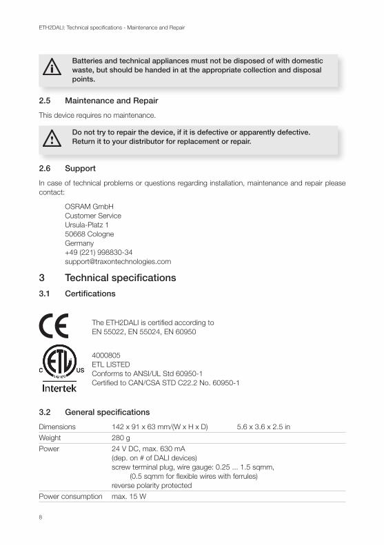
3 Technical specifications
3.1 Certifications
The ETH2DALI is certified according to EN 55022, EN 55024, EN 60950
4000805 ETL LISTED Conforms to ANSI/UL Std 60950-1 Certified to CAN/CSA STD C22.2 No. 60950-1
3.2 General specifications
Dimensions 142 x 91 x 63 mm/(W x H x D) 5.6 x 3.6 x 2.5 in
Weight 280 g
Power 24 V DC, max. 630 mA (dep. on # of DALI devices) screw terminal plug, wire gauge: 0.25 ... 1.5 sqmm, (0.5 sqmm for flexible wires with ferrules) reverse polarity protected
Power consumption max. 15 W
9
ETH2DALI: Technical specifications - Interface specifications
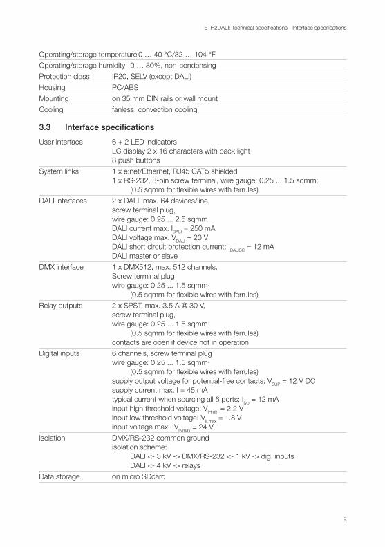
Operating/storage temperature 0 … 40 °C/32 … 104 °F
Operating/storage humidity 0 … 80%, non-condensing
Protection class IP20, SELV (except DALI)
Housing PC/ABS
Mounting on 35 mm DIN rails or wall mount
Cooling fanless, convection cooling
3.3 Interface specifications
User interface 6 + 2 LED indicators LC display 2 x 16 characters with back light 8 push buttons
System links 1 x e:net/Ethernet, RJ45 CAT5 shielded 1 x RS-232, 3-pin screw terminal, wire gauge: 0.25 ... 1.5 sqmm; (0.5 sqmm for flexible wires with ferrules)
DALI interfaces 2 x DALI, max. 64 devices/line, screw terminal plug, wire gauge: 0.25 ... 2.5 sqmm DALI current max. IDALI = 250 mA DALI voltage max. VDALI = 20 V DALI short circuit protection current: IDALISC = 12 mA DALI master or slave
DMX interface 1 x DMX512, max. 512 channels, Screw terminal plug wire gauge: 0.25 ... 1.5 sqmm,
(0.5 sqmm for flexible wires with ferrules)
Relay outputs 2 x SPST, max. 3.5 A @ 30 V, screw terminal plug, wire gauge: 0.25 ... 1.5 sqmm,
(0.5 sqmm for flexible wires with ferrules) contacts are open if device not in operation
Digital inputs 6 channels, screw terminal plug wire gauge: 0.25 ... 1.5 sqmm,
(0.5 sqmm for flexible wires with ferrules) supply output voltage for potential-free contacts: VSUP = 12 V DC supply current max. I = 45 mA typical current when sourcing all 6 ports: Ityp = 12 mA input high threshold voltage: VIHmin = 2.2 V input low threshold voltage: VILmax = 1.8 V input voltage max.: VINmax = 24 V
Isolation DMX/RS-232 common ground isolation scheme: DALI <- 3 kV -> DMX/RS-232 <- 1 kV -> dig. inputs DALI <- 4 kV -> relays
Data storage on micro SDcard
10
ETH2DALI: Device description - Functions and features
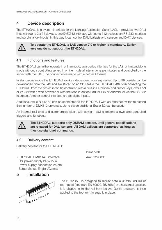
4 Device descriptionThe ETH2DALI is a system interface for the Lighting Application Suite (LAS). It provides two DALI lines with up to 2 x 64 devices, one DMX512 interface with up to 512 devices, an RS-232 interface and six digital dry inputs. In this way it can control DALI ballasts and sensors and DMX devices.
iTo operate the ETH2DALI a LAS version 7.0 or higher is mandatory. Earlier versions do not support the ETH2DALI.
4.1 Functions and features
The ETH2DALI can either operate in online mode, as a device interface for the LAS, or in standalone mode without a controlling server. In online mode all interactions are initiated and controlled by the server with the LAS. The connection is made with e:net via Ethernet.
In standalone mode the ETH2DALI works independent from any server. Up to 99 cuelists can be downloaded from the LAS and are stored on an SD card in the ETH2DALI. After disconnecting the ETH2DALI from the server, it can be controlled with a built-in LC display and cursor keys, over LAN or WLAN with a web browser or with the Mobile Action Pad for iOS or Android, or via the RS-232 interface. Another control interface are six digital inputs.
Additional e:cue Butler S2 can be connected to the ETH2DALI with an Ethernet switch to extend the number of DMX512 universes. Up to seven additional Butler S2 can be used.
An internal real-time and astronomical clock with saylight saving options allows time controlled triggers and functions.
iThe ETH2DALI supports only OSRAM sensors, until general specifications are released for DALI sensors. All DALI ballasts are supported, as long as they use standard commands.
4.2 Delivery content
Delivery content for the ETH2DALI:
Ident code
y ETH2DALI DMX/DALI interface AA752290035 Rail power supply 24 V/15 W Power supply connection 25 cm Setup Manual English/German
5 InstallationThe ETH2DALI is designed to mount onto a 35mm DIN rail or top-hat rail (standard EN 50022, BS 5584) in a horizontal position. It is clipped in to the rail from below. Gentle pressure is then applied to the top front to snap it in place.
11
ETH2DALI: Installation - Installation conditions
5.1 Installation conditions
Installation position: Terminals horizontal Horizontal spacing: min. 1 mm Minimum vertical rail grid spacing: 115 mm (90 + 25 mm) (excluding conduit) Recommended vertical rail grid spacing: 160 mm (with 40 mm conduit)
5.2 DALI line configuration
iDALI systems are not hot-plug capable. When connecting new DALI devices, reconfigure the DALI system with the Programmer of the LAS.
!For changes in the DALI wiring, always shut down the ETH2DALI. It performs a foreign voltage check on startup, to protect the DALI drivers in the ETH2DALI.
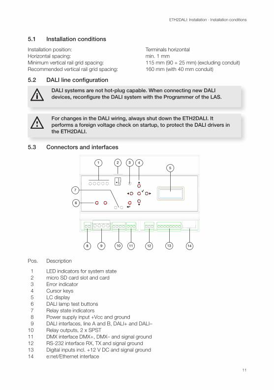
5.3 Connectors and interfaces
1 2 3 4
5
6
8 9 10 11 12 13 14
7
Pos. Description
1 LED indicators for system state 2 micro SD card slot and card 3 Error indicator 4 Cursor keys 5 LC display 6 DALI lamp test buttons 7 Relay state indicators 8 Power supply input +Vcc and ground 9 DALI interfaces, line A and B, DALI+ and DALI– 10 Relay outputs, 2 x SPST 11 DMX interface DMX+, DMX– and signal ground 12 RS-232 interface RX, TX and signal ground 13 Digital inputs incl. +12 V DC and signal ground 14 e:net/Ethernet interface

12
ETH2DALI: Installation - Connector details
5.4 Connector details
1 2 3 4
5
1 2 3 4
5
The 12 V DC supply is only meant for connecting potential-free switches. When using switches with external supply related to ground, input voltages can be in range of 5 to 24 V DC.
5.5 LED indicators
LED indicators group (pos. 1, from left to right):
y LED 1: green/red, DALI master/slave mode green = master, red = slave
y LED 2: green, status DALI output A on = DALI output powered flickering during data transmission off = DALI power off)
y LED 3: green, status DALI output B on = DALI output powered flickering during data transmission off = DALI power off)
y LED 4: yellow, Ethernet connection (link)
y LED 5: green, Ethernet activity
The Error indicator (pos. 3) lights up red in error conditions.
5.6 Cursor buttons
The six cursor buttons (pos. 4) are used for display navigation, scene selection, device configuration etc.
1
2
34 5
6
y Button 1: up
y Button 2: down
y Button 3: right
y Button 4: left
y Button 5: enter
y Button 6: cancel/shift (to alter functionality of other button)
13
ETH2DALI: Control over serial interface - micro SDcard
5.7 micro SDcard
The micro SDcard (in delivery content) is used for data storage like shows and Action Pad pages. Usually the micro SDcard needs no replacement, as it provides enough storage volume.
iNever remove the micro SDcard during operation. Shut down the ETH2DALI before removing the micro SDcard. The card may be damaged.
� Take care for proper ESD protection when touching the micro SDcard. Electrical discharges may damage the micro SDcard.
5.8 Ethernet connection
The pin-assignment of the Ethernet port corresponds to standards. You can use every common Ethernet component, like cable, splitters and switches.
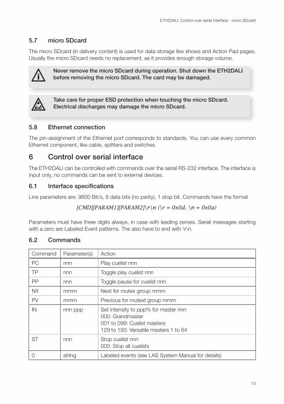
6 Control over serial interfaceThe ETH2DALI can be controlled with commands over the serial RS-232 interface. The interface is input only, no commands can be sent to external devices.
6.1 Interface specifications
Line parameters are: 9600 Bit/s, 8 data bits (no parity), 1 stop bit. Commands have the format
[CMD][PARAM1][PARAM2]\r\n (\r = 0x0d, \n = 0x0a)
Parameters must have three digits always, in case with leading zeroes. Serial messages starting with a zero are Labeled Event patterns. The also have to end with \r\n.
6.2 Commands
Command Parameter(s) Action
PC nnn Play cuelist nnn
TP nnn Toggle play cuelist nnn
PP nnn Toggle pause for cuelist nnn
NX mmm Next for mutex group mmm
PV mmm Previous for mutext group mmm
IN nnn ppp Set intensity to ppp% for master nnn 000: Grandmaster 001 to 099: Cuelist masters 129 to 193: Versatile masters 1 to 64
ST nnn Stop cuelist nnn 000: Stop all cuelists
0 string Labeled events (see LAS System Manual for details)

14
ETH2DALI: Configuration - Online configuration
Examples: Play Cuelist 1: PC001\r\n Set Grandmaster Intensity to 20%: IN000020\r\n
7 ConfigurationThere are three ways to configure the ETH2DALI:
yWith the Programmer and the Device Manager of the LAS, when the ETH2DALI is used in online mode.
yWith a connected Ethernet switch, a LAN or WLAN connection to a PC or mobile device and a web browser in standalone mode.
yWith the LC display and buttons on the ETH2DALI.
7.1 Online configuration
When in factory state, the ETH2DALI has an IP address of 192.168.123.1, also when the ETH2DALI has been reset to factory state.
iNever connect more than one ETH2DALI in factory state to a network. The identical IP addresses will conflict and disturb proper communication.
LAS server
Ethernet switch
ETH2DALI
RJ45 Cat5RJ45 Cat5
Connect the server running the Lighting Application Suite (LAS). to an Ethernet switch, connect the ETH2DALI to the same switch using RJ45 standard cables.
iTo set system parameters with the Programmer, the ETH2DALI must not be used in the Device Manager of the Programmer. Remove it from the Device Manager before changing parameters.
Start the Programmer of the LAS. In the upper left window, click the Network tab. The ETH2DALI should be visible in the list of devices. If the ETH2DALI is not shown in this list, check the network connections and that your LAS host is in the same IP address space and the netmask is correct. Make sure that the ETH2DALI is not loaded in the Device Manager of the Programmer and no driver is active. Double-click on the ETH2DALI and the configuration dialog opens.
Grey fields are read-only values, only white fields can be changed. Assign at least a unique and valid IP address, a netmask and no gateway. Set the Base Time (which is the time in your region without daylight saving time offset). Give the device a unique name.

15
ETH2DALI: Configuration - Online configuration
The Group ID is used for clustering standalone engines. If used only online, leave the Group ID as it is. The Config Password is used, when the ETH2DALI is configured standalone with a web browser. The default password is “ecue”.
Do not change parameters in the Advanced Setup, unless advised to do so. These parameters set timing and behavior for the DMX and DALI communication. Close the dialog with OK.
Start the Device Manager of the Programmer and execute the Automatic Device Setup Wizard. The ETH2DALI will be found and displayed as three devices for DALI, DMX and digital inputs/relays outputs (terminals).
Double-click on the DALI device to set the parameters for the DALI interface.
The parameters Enable Driver and Private Logbook are common to all dialogs. You can enable/disable the device and a separated log book in the Programmer. Give the device a unique alias name. A comment helps to identify the device in the Device Manager and in the system.
The Export parameters are usually assigned when exporting a show from the Programmer to the engine for standalone mode. You can also enable or disable the daylight saving time adjustment and the use of a web browser with this ETH2DALI. Close the dialog with OK.
16
ETH2DALI: Configuration - Online configuration
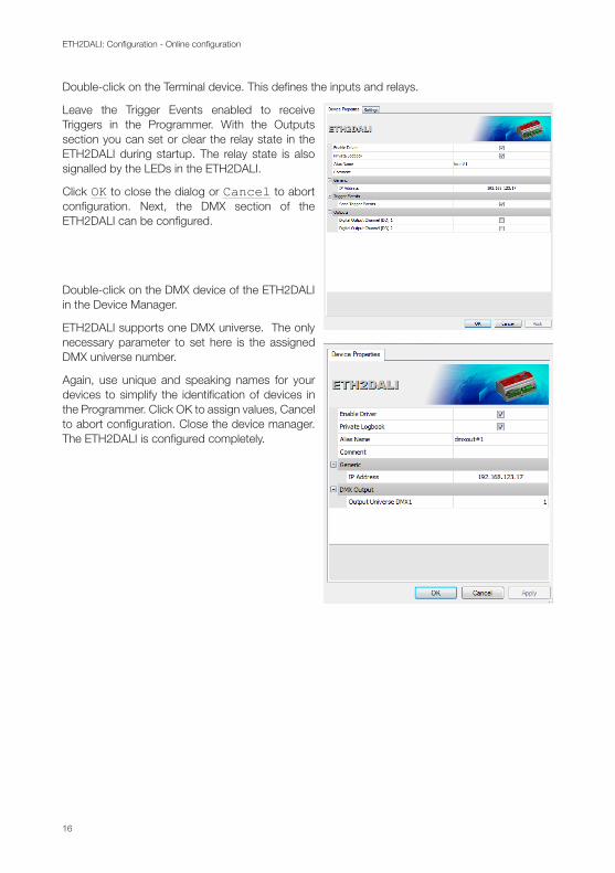
Double-click on the Terminal device. This defines the inputs and relays.
Leave the Trigger Events enabled to receive Triggers in the Programmer. With the Outputs section you can set or clear the relay state in the ETH2DALI during startup. The relay state is also signalled by the LEDs in the ETH2DALI.
Click OK to close the dialog or Cancel to abort configuration. Next, the DMX section of the ETH2DALI can be configured.
Double-click on the DMX device of the ETH2DALI in the Device Manager.
ETH2DALI supports one DMX universe. The only necessary parameter to set here is the assigned DMX universe number.
Again, use unique and speaking names for your devices to simplify the identification of devices in the Programmer. Click OK to assign values, Cancel to abort configuration. Close the device manager. The ETH2DALI is configured completely.
17
ETH2DALI: Configuration - Standalone configuration with a web browser
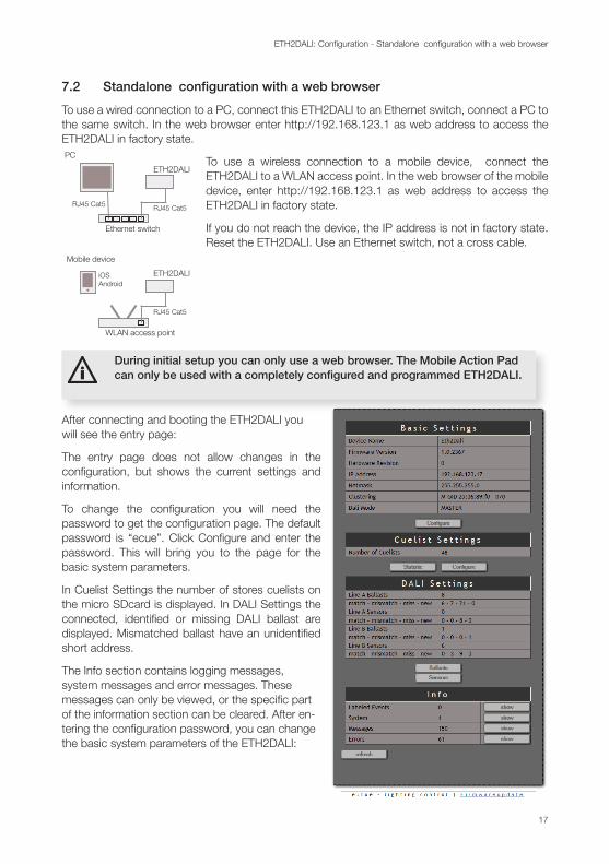
7.2 Standalone configuration with a web browser
To use a wired connection to a PC, connect this ETH2DALI to an Ethernet switch, connect a PC to the same switch. In the web browser enter http://192.168.123.1 as web address to access the ETH2DALI in factory state. PC
Ethernet switch
ETH2DALI
RJ45 Cat5RJ45 Cat5
Mobile device
WLAN access point
ETH2DALI
RJ45 Cat5
iOSAndroid
To use a wireless connection to a mobile device, connect the ETH2DALI to a WLAN access point. In the web browser of the mobile device, enter http://192.168.123.1 as web address to access the ETH2DALI in factory state.
If you do not reach the device, the IP address is not in factory state. Reset the ETH2DALI. Use an Ethernet switch, not a cross cable.
iDuring initial setup you can only use a web browser. The Mobile Action Pad can only be used with a completely configured and programmed ETH2DALI.
After connecting and booting the ETH2DALI you will see the entry page:
The entry page does not allow changes in the configuration, but shows the current settings and information.
To change the configuration you will need the password to get the configuration page. The default password is “ecue”. Click Configure and enter the password. This will bring you to the page for the basic system parameters.
In Cuelist Settings the number of stores cuelists on the micro SDcard is displayed. In DALI Settings the connected, identified or missing DALI ballast are displayed. Mismatched ballast have an unidentified short address.
The Info section contains logging messages, system messages and error messages. These messages can only be viewed, or the specific part of the information section can be cleared. After en-tering the configuration password, you can change the basic system parameters of the ETH2DALI:
18
ETH2DALI: Configuration - Display messages and standalone setup
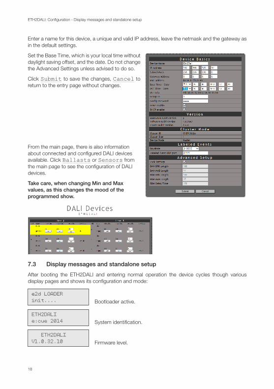
Enter a name for this device, a unique and valid IP address, leave the netmask and the gateway as in the default settings.
Set the Base Time, which is your local time without daylight saving offset, and the date. Do not change the Advanced Settings unless advised to do so.
Click Submit to save the changes, Cancel to return to the entry page without changes.
From the main page, there is also information about connected and configured DALI devices available. Click Ballasts or Sensors from the main page to see the configuration of DALI devices.
Take care, when changing Min and Max values, as this changes the mood of the programmed show.
7.3 Display messages and standalone setup
After booting the ETH2DALI and entering normal operation the device cycles though various display pages and shows its configuration and mode:
: e2d LOADERinit.... Bootloader active.
ETH2DALIe:cue 2014 System identification.
ETH2DALIV1.0.32.10 Firmware level.

19
ETH2DALI: Configuration - Display messages and standalone setup
ETH2DALIscanning... Scanning DALI lines, end of boot phase.
17.07.201416:42:38 Date and system time.
IP:192.168.123.045 IP address.
MASK:255.255.255.0 Netmask in use.
MAC:0016:1c:f1:17:ab MAC address of this ETH2DALI.
Connection:192.168.123.10 Connected LAS server, if in online mode or.
Connection:--- offline --- No connection to LAS server.
IN: 1 2 3 4 5 6 o C o o o o State of digital inputs, o = off, C = on.
Cuelists:012 - 01 playing Cuelists on micro SDcard and running cuelists.
Mode:DALI MASTER ETH2DALI is a master or slave.
DMX Cluster:02 (bd:fe:91:0d) Running as a DMX cluster, ID of the cluster.
Bus Current (mA)A:104,8 B:19,2 Actual supply current on DALI busses.
Bus State:A:OK B:OK Status of DALI buses.
20
ETH2DALI: Configuration - Standalone configuration with buttons and display
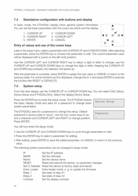
7.4 Standalone configuration with buttons and display
1
2
34 5
6
In basic mode, the ETH2DALI display show general system information. You can set the basic parameters with the cursor key block and the display.
1 - CURSOR UP 2 - CURSOR DOWN 3 - CURSOR RIGHT 4 - CURSOR LEFT 5 - ENTER 6 - CANCEL
Entry of values and use of the cursor keys
Later in the setup menu, select a parameter with CURSOR UP and CURSOR DOWN. After selecting a parameter, press the ENTER key to choose this parameter to edit. The current parameter value will be displayed with a cursor on the left most position.
Use the CURSOR LEFT and CURSOR RIGHT key to select a digit or letter to change, use the CURSOR UP and CURSOR DOWN keys to change the digit or letter. Keeping the CURSOR UP and DOWN keys pressed, the selection will speed up.
After the parameter is complete, press ENTER to assign the new value or CANCEL to return to the previous state. For some functions an N is displayed, change this to Y and press ENTER to execute the function like RESET or DEFAULTS.
7.5 System setup
From the start display use the CURSOR UP or CURSOR DOWN key. You can select DALI Setup, Device Setup and ETH2DALI/time. Select the display Device Setup.
Device SetupPress the ENTER key to enter the setup mode. The ETH2DALI leaves the basic display mode and asks for a password to change basic system parameters.
Password_
The ETH2DALI asks for a password to change the setup. Default password in factory state is “ecue”. Use the four cursor keys to se-lect a character and CURSOR LEFT and RIGHT to change position. Press ENTER.
You will now enter the setup mode.
y Use the CURSOR UP and CURSOR DOWN keys to cycle though parameters to edit.
y Press the ENTER key to select a parameter for editing.
y After editing, press ENTER to save the edited parameter, or CANCEL to return to the previous value.
The following system parameters can be changed in setup mode:
IP Set the IP address MASK Set the netmask Name Set the device name RESET Reset and reboot) the device, no parameter changes Set to Defaults Reset the device to factory state and reboot Enter Loader Enter loader mode, e. g. to update the firmware Relay 1 Set state of relay #1 Relay 2 Set state of relay #2 Contrast Set the display contrast
21
ETH2DALI: Configuration - DALI setup
While in parameter selection, use the CURSOR LEFT key to return to the state to select Device Setup, DALI Setup or ETH2DALI/time.
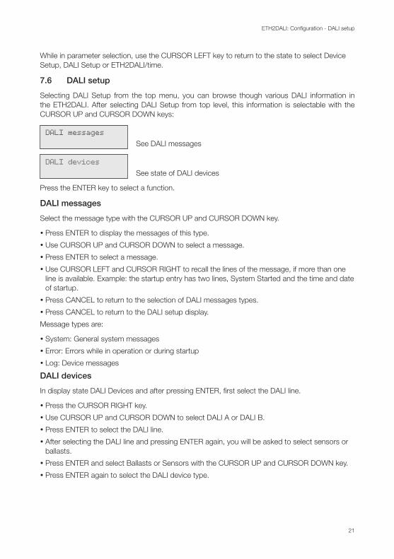
7.6 DALI setup
Selecting DALI Setup from the top menu, you can browse though various DALI information in the ETH2DALI. After selecting DALI Setup from top level, this information is selectable with the CURSOR UP and CURSOR DOWN keys:
DALI messagesSee DALI messages
DALI devicesSee state of DALI devices
Press the ENTER key to select a function.
DALI messages
Select the message type with the CURSOR UP and CURSOR DOWN key.
y Press ENTER to display the messages of this type.
y Use CURSOR UP and CURSOR DOWN to select a message.
y Press ENTER to select a message.
y Use CURSOR LEFT and CURSOR RIGHT to recall the lines of the message, if more than one line is available. Example: the startup entry has two lines, System Started and the time and date of startup.
y Press CANCEL to return to the selection of DALI messages types.
y Press CANCEL to return to the DALI setup display.
Message types are:
y System: General system messages
y Error: Errors while in operation or during startup
y Log: Device messages
DALI devices
In display state DALI Devices and after pressing ENTER, first select the DALI line.
y Press the CURSOR RIGHT key.
y Use CURSOR UP and CURSOR DOWN to select DALI A or DALI B.
y Press ENTER to select the DALI line.
y After selecting the DALI line and pressing ENTER again, you will be asked to select sensors or ballasts.
y Press ENTER and select Ballasts or Sensors with the CURSOR UP and CURSOR DOWN key.
y Press ENTER again to select the DALI device type.
22
ETH2DALI: Test mode - DALI test buttons
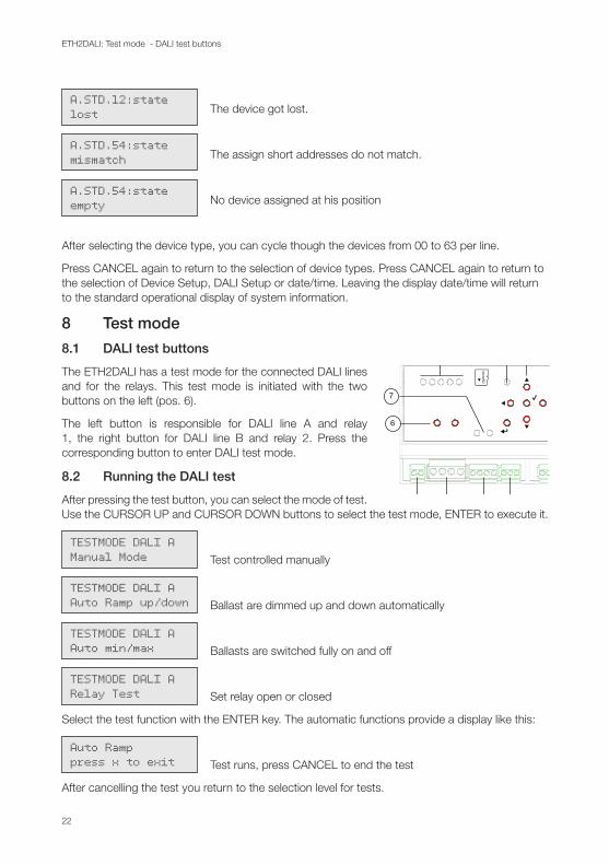
A.STD.12:statelost The device got lost.
A.STD.54:statemismatch The assign short addresses do not match.
A.STD.54:stateempty No device assigned at his position
After selecting the device type, you can cycle though the devices from 00 to 63 per line.
Press CANCEL again to return to the selection of device types. Press CANCEL again to return to the selection of Device Setup, DALI Setup or date/time. Leaving the display date/time will return to the standard operational display of system information.
8 Test mode
8.1 DALI test buttons 1 2 3 4
5
6
8 9 10 11 12 13 14
7
The ETH2DALI has a test mode for the connected DALI lines and for the relays. This test mode is initiated with the two buttons on the left (pos. 6).
The left button is responsible for DALI line A and relay 1, the right button for DALI line B and relay 2. Press the corresponding button to enter DALI test mode.
8.2 Running the DALI test
After pressing the test button, you can select the mode of test. Use the CURSOR UP and CURSOR DOWN buttons to select the test mode, ENTER to execute it.
TESTMODE DALI AManual Mode Test controlled manually
TESTMODE DALI AAuto Ramp up/down Ballast are dimmed up and down automatically
TESTMODE DALI AAuto min/max Ballasts are switched fully on and off
TESTMODE DALI ARelay Test Set relay open or closed
Select the test function with the ENTER key. The automatic functions provide a display like this:
Auto Ramppress x to exit Test runs, press CANCEL to end the test
After cancelling the test you return to the selection level for tests.
23
ETH2DALI: Firmware update - Device Override
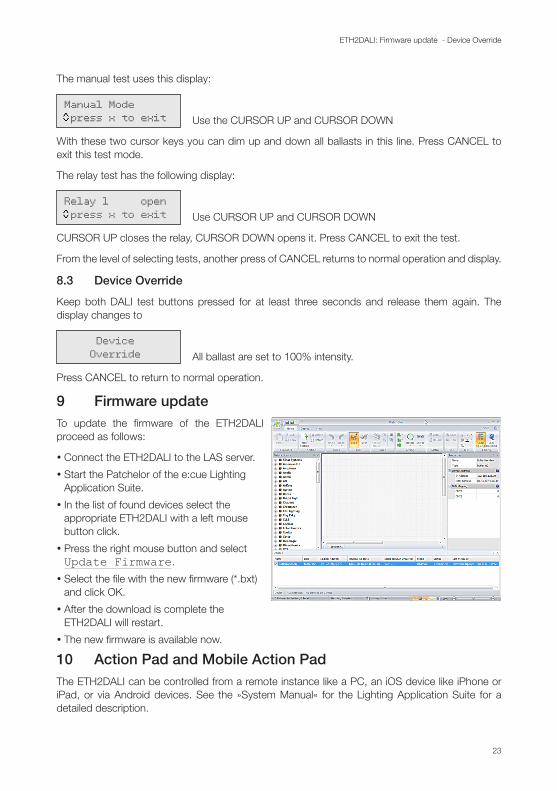
The manual test uses this display:
Manual Mode press x to exit Use the CURSOR UP and CURSOR DOWN
With these two cursor keys you can dim up and down all ballasts in this line. Press CANCEL to exit this test mode.
The relay test has the following display:
Relay 1 open press x to exit Use CURSOR UP and CURSOR DOWN
CURSOR UP closes the relay, CURSOR DOWN opens it. Press CANCEL to exit the test.
From the level of selecting tests, another press of CANCEL returns to normal operation and display.
8.3 Device Override
Keep both DALI test buttons pressed for at least three seconds and release them again. The display changes to
Device Override All ballast are set to 100% intensity.
Press CANCEL to return to normal operation.
9 Firmware update To update the firmware of the ETH2DALI proceed as follows:
y Connect the ETH2DALI to the LAS server.
y Start the Patchelor of the e:cue Lighting Application Suite.
y In the list of found devices select the appropriate ETH2DALI with a left mouse button click.
y Press the right mouse button and select Update Firmware.
y Select the file with the new firmware (*.bxt) and click OK.
y After the download is complete the ETH2DALI will restart.
y The new firmware is available now.
10 Action Pad and Mobile Action PadThe ETH2DALI can be controlled from a remote instance like a PC, an iOS device like iPhone or iPad, or via Android devices. See the »System Manual« for the Lighting Application Suite for a detailed description.
11 Problem analysis
11.1 Error display messages
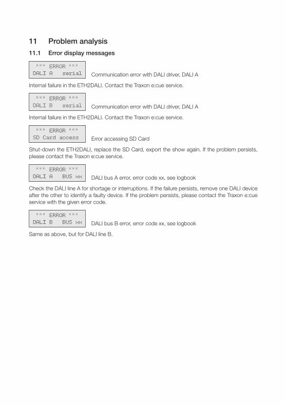
*** ERROR ***DALI A serial Communication error with DALI driver, DALI A
Internal failure in the ETH2DALI. Contact the Traxon e:cue service.
*** ERROR ***DALI B serial Communication error with DALI driver, DALI A
Internal failure in the ETH2DALI. Contact the Traxon e:cue service.
*** ERROR ***SD Card access Error accessing SD Card
Shut-down the ETH2DALI, replace the SD Card, export the show again. If the problem persists, please contact the Traxon e:cue service.
*** ERROR ***DALI A BUS xx DALI bus A error, error code xx, see logbook
Check the DALI line A for shortage or interruptions. If the failure persists, remove one DALI device after the other to identify a faulty device. If the problem persists, please contact the Traxon e:cue service with the given error code.
*** ERROR ***DALI B BUS xx DALI bus B error, error code xx, see logbook
Same as above, but for DALI line B.

Deutsch
26
ETH2DALI: Sicherheitshinweise - Symbole
12 SicherheitshinweiseLesen Sie die Sicherheitshinweise im zusätzlichen Heft sorgfältig. Stellen Sie sicher, dass die angegebenen Umgebungsbedingungen, Montage- und Installationsvoraussetzungen eingehalten werden. Diese Anleitung sollte an einem sicheren Ort in der Nähe des Installationsortes aufbewahrt werden.
12.1 Symbole
!Das Ausrufezeichen warnt vor Gefahren für Personen oder Schäden am Produkt.
iDas Informationssymbol gibt generelle Hinweise und informiert über Handhabung oder Verfahren zur Verwendung des Gerätes.
12.2 Hinweise
!Die DALI-Leitungen dürfen nur angeschlossen werden, wenn der ETH2DALI ausgeschaltet ist, da nur beim Einschalten auf Fremdspannung geprüft wird. Fremdspanung auf den DALI-Leitung kann zur Zerstörung des Gerätes führen!
iSollte das beigelegte Heft mit den Sicherheitshinweisen fehlen, wenden Sie sich bitte an Traxon Technologies für ein zusätzliches Exemplar.
13 Allgemeine Hinweise
13.1 Transport
Transportieren Sie den ETH2DALI nur in seiner originalen Verpackung um Schäden zu vermeiden. Entpacken Sie den ETH2DALI nur am Installationsort. Um Schäden bei Wechsel von Kälte zu Wärme durch Kondensationswasser zu verhindern, warten Sie nach dem Auspacken, bis das Gerät die Temperatur am Installationsort angenommen hat.
13.2 Entpacken und Lieferumfang
Entpacken Sie den ETH2DALI und überprüfen Sie die Vollständigkeit des Lieferumfanges nach Kapitel „15.2 Lieferumfang“ Bewahren Sie die Verpackung für einen späteren Transport auf. Sollten Komponenten beschädigt sein oder fehlen, wenden Sie sich an Ihren e:cue-Service.
13.3 Garantiebestimmungen
Abhängig vom Produkt können Garantie und Gewährleistung zeitlich unterschiedlich befristet sein. Die Garantie- und Gewährleistungs-Bestimmungen finden sich in der Regel im Angebot und in der Auftragsbestätigung. Zusätzlich sind Informationen dazu in unserer Website unter “Allgemeine Geschäftsbedingungen” aufgeführt. Gesetzlich geregelte Garantiebedingungen sind davon unberührt.
27
ETH2DALI: Technische Daten - Entsorgung
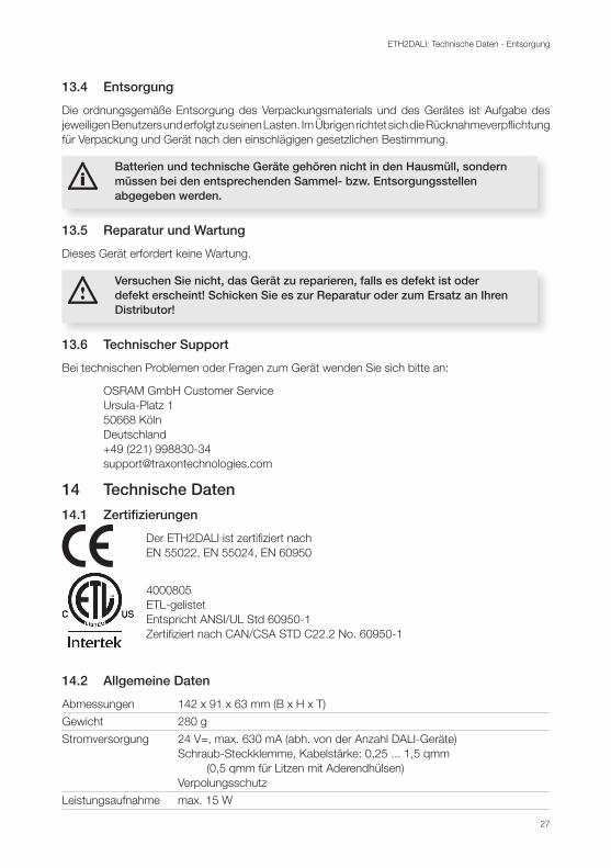
13.4 Entsorgung
Die ordnungsgemäße Entsorgung des Verpackungsmaterials und des Gerätes ist Aufgabe des jeweiligen Benutzers und erfolgt zu seinen Lasten. Im Übrigen richtet sich die Rücknahmeverpflichtung für Verpackung und Gerät nach den einschlägigen gesetzlichen Bestimmung.
iBatterien und technische Geräte gehören nicht in den Hausmüll, sondern müssen bei den entsprechenden Sammel- bzw. Entsorgungsstellen abgegeben werden.
13.5 Reparatur und Wartung
Dieses Gerät erfordert keine Wartung.
!Versuchen Sie nicht, das Gerät zu reparieren, falls es defekt ist oder defekt erscheint! Schicken Sie es zur Reparatur oder zum Ersatz an Ihren Distributor!
13.6 Technischer Support
Bei technischen Problemen oder Fragen zum Gerät wenden Sie sich bitte an:
OSRAM GmbH Customer Service Ursula-Platz 1 50668 Köln Deutschland +49 (221) 998830-34 [email protected]
14 Technische Daten
14.1 Zertifizierungen
Der ETH2DALI ist zertifiziert nach EN 55022, EN 55024, EN 60950
4000805 ETL-gelistet Entspricht ANSI/UL Std 60950-1 Zertifiziert nach CAN/CSA STD C22.2 No. 60950-1
14.2 Allgemeine Daten
Abmessungen 142 x 91 x 63 mm (B x H x T)
Gewicht 280 g
Stromversorgung 24 V=, max. 630 mA (abh. von der Anzahl DALI-Geräte) Schraub-Steckklemme, Kabelstärke: 0,25 ... 1,5 qmm (0,5 qmm für Litzen mit Aderendhülsen) Verpolungsschutz
Leistungsaufnahme max. 15 W
28
ETH2DALI: Technische Daten - Schnittstellen
Betriebs-/Lagertemperatur 0 … 40 °C
Betriebs-/Lagerfeuchte 0 … 80%, nicht kondensierend
Schutzklasse IP20, SELV (außer DALI)
Gehäuse PC/ABS
Montage auf 35 mm-DIN-Hutschiene
Kühlung lüfterlos, Konvektionskühlung
14.3 Schnittstellen
Benutzerschnittstellen 6 + 2 LEDs LC-Display 2 x 16 Zeichen/ Hintergrundbeleuchtung 8 Taster
Systemverbindungen 1 x e:net/Ethernet, RJ45 CAT5 geschirmt 1 x RS-232, 3-pol. Schraub-Steckklemme Kabelstärke: 0,25 ... 1,5 qmm;
(0,5 qmm für Litze mit Aderendhülsen)
DALI-Schnittstellen 2 x DALI, max. 64 Geräte pro Linie, Schraub-Steckklemmen, Kabelstärke: 0,25 ... 2,5 qmm DALI-Stromlast max. IDALI = 250 mA DALI-Spannung max. VDALI = 20 V DALI-Kurzschlusstrom: IDALISC = 12 mA DALI-Master oder -Slave
DMX-Schnittstelle 1 x DMX512, max. 512 Kanäle, Schraub-Steckklemmen Kabelstärke: 0,25 ... 1,5 qmm,
(0,5 qmm für Litze mit Aderendhülsen)
Relais-Ausgänge 2 x einpolig EIN max. 3,5 A bei 30 V, Schraub-Steckklemmen, Kabelstärke: 0,25 ... 1,5 qmm,
(0,5 qmm für Litze mit Aderendhülsen) Kontakte offen, wenn Gerät stromlos
Digitale Eingänge 6 Kanäle, Schraub-Steckklemmen Kabelstärke: 0,25 ... 1,5 qmm,
(0,5 qmm für Litze mit Aderendhülsen) Spannungsversorgung für potentialfreie Kontakte: VSUP = 12 V= Max. Ausgangsstrom I = 45 mA Typischer Strom für alle 6 Kanäle: Ityp = 12 mA Min Eingangsspannung für Ein: VIHmin = 2,2 V Max. Eingangsspannung für Aus: VILmax = 1,8 V Max. Eingangsspannung: VINmax = 24 V
Isolation DMX/RS-232 gemeinsame Masse Isolationsschema: DALI <- 3 kV -> DMX/RS-232 <- 1 kV -> dig. Eingänge

29
ETH2DALI: Gerätebeschreibung - Funktionen und Eigenschaften
DALI <- 4 kV -> Relais
Datenspeicherung auf micro SDcard
15 GerätebeschreibungETH2DALI ist eine Engine und ein Interface für die Lighting Application Suite (LAS). Sie stellt zwei DALI-Linien mit bis zu 64 Geräten pro Linie bereit sowie ein DMX-Interface für bis zu 512 Kanäle, eine RS-232-Schnittstelle und sechs digitale Eingänge. Somit können sowohl DALI-Geräte als auch DMX-Systeme betrieben werden.
iFür ETH2DALI ist eine LAS-Version ab 7.0 erforderlich. Frühere Versionen unterstützen ETH2DALI nicht.
15.1 Funktionen und Eigenschaften
ETH2DALI arbeitet entweder im Online-Modus, als Systemschnittstelle für die LAS, oder als Einzelgerät ohne einen Server im Hintergrund. Im Online-Modus werden alle Aktivitäten von einem Server mit der LAS initiiert. Die Systemanbindung erfolgt über e:net/Ethernet.
Als Einzelgerät (standalone) arbeitet ETH2DALI unabhängig von einem Server. Bis zu 99 Cuelisten können mit der LAS herauntergeladen werden und werden auf einer SD-Karte gespeichert. Nach der Trennung vom Server kann ETH2DALI über Taster und das LC-Display gesteuert werden, oder über LAN und WLAN mit einem Webbrowser oder das Mobile Action Pad für iOS und Android, oder über die RS-232-Schnittstelle. Ebenso kann die Steuerung über die digitalen Eingänge erfolgen.
Es können weitere e:cue Butler S2 an den ETH2DALI angeschlossen werden, um die Anzahl an DMX-Universen zu erweitern. Bis zu sieben zusätzliche Systeme sind möglich.
Eine integrierte Echtzeit- und astronomische Uhr mit Sommer-/Winterzeitumstellung erlaubt zeit- und datumsbezogene Funktionen.
iDer ETH2DALI unterstützt nur OSRAM-Sensoren, bis Standards für Sensoren verfügbar sind. Als Ballasts werden alle Systeme unterstützt, solange sie die Standardbefehle nutzen.
15.2 Lieferumfang
Lieferumfang des ETH2DALI:
Ident-Code
y ETH2DALI DMX/DALI-Interface AA752290035 Hutschienen-Netzteil 24 V=/15 W Anschlusskabel Netzteil 25 cm Setup Manual Englisch/Deutsch

30
ETH2DALI: Installation - Montagebedingungen
16 InstallationDer ETH2DALI ist für die Montage auf einer 35 mm-DIN-Hutschiene in horizontaler Position ausgelegt. (Standard EN 50022, BS 5584). Er wird von unten auf die Schiene gedrückt. Mit leichtem Druck auf die Oberfläche rastet er auf der Schiene ein.
16.1 Montagebedingungen
Mögliche Positionen: Anschlüsse horizontal Horizontaler Abstand: min. 1 mm Minimaler vertikaler Abstand: 115 mm (90 + 25 mm) (ohne Kabelkanal) Empfohlener vertikaler Abstand: 160 mm (mit 40 mm-Kabelkanal)
Änderungen der Verkabelung
iDALI-Systeme sind nicht hotplug-fähig. Nach dem Hinzufügen neuer Geräte muss die Konfiguration mit dem Programmer der LAS erneuert werden.
!Vor Änderungen in der Verkabelung den ETH2DALI ausschalten. Nur beim Einschalten führt er eine Prüfung auf Fremdspannung durch, um die DALI-Treiber zu schützen.
16.2 Anschlüsse und Schnittstellen
1 2 3 4
5
6
8 9 10 11 12 13 14
7
Pos. Beschreibung
1 LEDs zur Anzeige des Systemstatus 2 micro SDcard-Öffnung mit Karte 3 Fehler-Anzeige 4 Cursor-Tasten 5 LC-Display

31
ETH2DALI: Installation - Anschlussdetails
6 Taster für DALI Lampentest 7 Anzeigen für Relaisstatus (An = geschlossen) 8 Netzteilanschluss +Vcc und Masse 9 DALI-Schnittstellen, Linien A und B, DALI+ und DALI– 10 Relaisausgänge, 2 x einpolig ein 11 DMX-Schnittstelle DMX+, DMX– und Signalmasse 12 RS-232-Schnittstelle RX, TX und Signalmasse 13 Digitale Eingänge inkl. +12 V= und Signalmasse 14 e:net/Ethernet-Schnittstelle
16.3 Anschlussdetails
1 2 3 4
5
1 2 3 4
5
Die Spannungsversorgung von 12 V= ist nur bei Verwendung potentialfreier Schalter zu verwenden. Bei Schalter mit externer Spannungsversorgung in Bezug auf Gerätemasse darf die Eingangsspannung 5 bis 24 V= betragen.
16.4 LED-Anzeigen
LED-Anzeigen oben, von links nach rechts:
y LED 1: grün/rot, DALI Master- oder Slave-Modus Grün: Master, rot: Slave
y LED 2: grün, Status DALI-Ausgang A ein: DALI-Ausgang unter Spannung flackert während der Datenübertragung aus: keine DALI-Spannungsversorgung
y LED 3: grün, Status DALI-Ausgang B ein: DALI-Ausgang unter Spannung flackert während der Datenübertragung aus: keine DALI-Spannungsversorgung
y LED 4: gelb, Ethernet-Verbindung (Link)
y LED 5: grün, Ethernet-Aktivität
In Fehlersituationen leuchtet Die Fehleranzige-LED rot (Pos. 3).
32
ETH2DALI: Steuerung über serielle Schnittstelle - Cursor-Taster
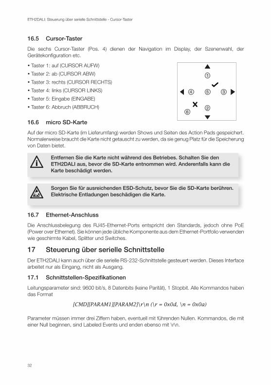
16.5 Cursor-Taster
Die sechs Cursor-Taster (Pos. 4) dienen der Navigation im Display, der Szenenwa
1
2
34 5
6
hl, der Gerätekonfiguration etc.
y Taster 1: auf (CURSOR AUFW)
y Taster 2: ab (CURSOR ABW)
y Taster 3: rechts (CURSOR RECHTS)
y Taster 4: links (CURSOR LINKS)
y Taster 5: Eingabe (EINGABE)
y Taster 6: Abbruch (ABBRUCH)
16.6 micro SD-Karte
Auf der micro SD-Karte (im Lieferumfang) werden Shows und Seiten des Action Pads gespeichert. Normalerweise braucht die Karte nicht getauscht zu werden, da sie genug Platz für die Speicherung von Daten bietet.
iEntfernen Sie die Karte nicht während des Betriebes. Schalten Sie den ETH2DALI aus, bevor die SD-Karte entnommen wird. Anderenfalls kann die Karte beschädigt werden.
� Sorgen Sie für ausreichenden ESD-Schutz, bevor Sie die SD-Karte berühren. Elektrische Entladungen beschädigen die Karte.
16.7 Ethernet-Anschluss
Die Anschlussbelegung des RJ45-Ethernet-Ports entspricht den Standards, jedoch ohne PoE (Power over Ethernet). Sie können jede übliche Komponente aus dem Ethernet-Portfolio verwenden wie geschirmte Kabel, Splitter und Switches.
17 Steuerung über serielle SchnittstelleDer ETH2DALI kann auch über die serielle RS-232-Schnittstelle gesteuert werden. Dieses Interface arbeitet nur als Eingang, nicht als Ausgang.
17.1 Schnittstellen-Spezifikationen
Leitungsparameter sind: 9600 bit/s, 8 Datenbits (keine Parität), 1 Stopbit. Alle Kommandos haben das Format
[CMD][PARAM1][PARAM2]\r\n (\r = 0x0d, \n = 0x0a)
Parameter müssen immer drei Ziffern haben, eventuell mit führenden Nullen. Kommandos, die mit einer Null beginnen, sind Labeled Events und enden ebenso mit \r\n.
33
ETH2DALI: Konfiguration - Kommandos
17.2 Kommandos
Kommando Parameter Action
PC nnn Spiele Cuelist nnn
TP nnn Wechsle Spielen/Stop für Cuelist nnn
PP nnn Wechsle Spielen/Pause für Cuelist nnn
NX mmm Nächste in Mutex Group mmm
PV mmm Vorherige in Mutex Group mmm
IN nnn ppp Setze Helligkeit auf ppp% für Master nnn 000: Grandmaster 001 bis 099: Cuelist Masters 129 bis 193: Versatile Masters 1 bis 64
ST nnn Stoppe Cuelist nnn 000: Stoppe alle Cuelists
0 string Labeled Events (siehe System Manual der LAS)
Beispiele: Spiele Cuelist 1: PC001\r\n Setze Grandmaster Helligkeit auf 20%: IN000020\r\n
18 KonfigurationEs gibt drei Wege, den ETH2DALI zu konfigurieren:
y Mit dem Programmer LAS, wenn der ETH2DALI im Online-Modus ist.
y Im Standalone-Modus mit einem angeschlossenen Ethernet-Switch, über eine LAN oder WLAN-Verbindung zu einem PC oder zu einem Mobilgerät zu einem Webbrowser.
y Über das LC-Display und die Taster des ETH2DALI.
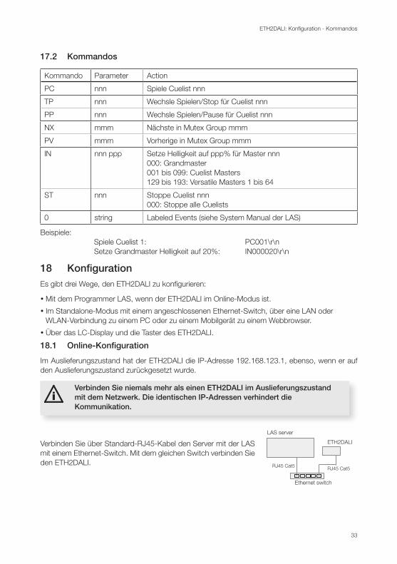
18.1 Online-Konfiguration
Im Auslieferungszustand hat der ETH2DALI die IP-Adresse 192.168.123.1, ebenso, wenn er auf den Auslieferungszustand zurückgesetzt wurde.
iVerbinden Sie niemals mehr als einen ETH2DALI im Auslieferungszustand mit dem Netzwerk. Die identischen IP-Adressen verhindert die Kommunikation.
LAS server
Ethernet switch
ETH2DALI
RJ45 Cat5RJ45 Cat5
Verbinden Sie über Standard-RJ45-Kabel den Server mit der LAS mit einem Ethernet-Switch. Mit dem gleichen Switch verbinden Sie den ETH2DALI.

34
ETH2DALI: Konfiguration - Online-Konfiguration
iUm die Basiswerte des ETH2DALI über den Programmer zu setzten, darf er nicht im Device Manager des Programmers verwendet werden.
Starten Sie den Programmer der LAS. Wählen Sie den Network-Reiter im Fenster oben links. Der ETH2DALI sollte dort sichtbar sein. Wird der ETH2DALI dort nicht angezeigt, überprüfen Sie die Verkabelung und stellen Sie sicher, dass sich Programmer und ETH2DALI im gleichen Addressbereich 192.168.123.* befinden. Führen Sie einen Doppelclick auf den ETH2DALI aus, ein Dialogfester für die Konfiguration öffnet sich.
Graue Werte werden nur angezeigt und können nicht geändert werden. Geben Sie dem Gerät eine gültige und eindeutige IP-Adresse, eine Netzmaske ohne Gateway. Stellen Sie die Basiszeit (ohne Sommerzeit-Versatz) ein und versehen Sie das Gerät mit einem eindeutigen Namen.
Die Group ID dient der Clusterung im Standalone-Modus. Lassen Sie im Online-Betrieb die ID unverändert. Das Config Password wird benötigt, wenn der ETH2DALI mit einem Webbrowser oder über die Taster konfiguriert wird. Das Standard-Password ist “ecue”. Ändern Sie keine Paraneter im Bereich Advanced Setup, es sei denn, Sie werden vom Support dazu aufgefordert. Diese Parameter betreffen die DALI- und DMX-Konfiguration.
Schließen Sie den Dialog mit OK. Starten Sie den Device Manager des Programmers und führen Sie den Automatic Device Setup Wizard aus. Der ETH2DALI wird gefunden und als drei Geräte angezeigt, für DALI-, DMX- und digitale Eingänge/Relais.
35
ETH2DALI: Konfiguration - Online-Konfiguration
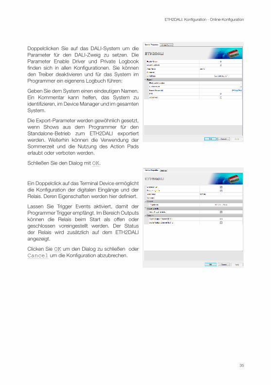
Doppelclicken Sie auf das DALI-System um die Parameter für den DALI-Zweig zu setzen. Die Parameter Enable Driver und Private Logbook finden sich in allen Konfigurationen. Sie können den Treiber deaktivieren und für das System im Programmer ein eigenens Logbuch führen:
Geben Sie dem System einen eindeutigen Namen. Ein Kommentar kann helfen, das System zu identifizieren, im Device Manager und im gesamten System.
Die Export-Parameter werden gewöhnlich gesetzt, wenn Shows aus dem Programmer für den Standalone-Betrieb zum ETH2DALI exportiert werden. Weiterhin können die Verwendung der Sommerzeit und die Nutzung des Action Pads erlaubt oder verboten werden.
Schließen Sie den Dialog mit OK.
Ein Doppelclick auf das Terminal Device ermöglicht die Konfiguration der digitalen Eingänge und der Relais. Deren Eigenschaften werden hier definiert.
Lassen Sie Trigger Events aktiviert, damit der Programmer Trigger empfängt. Im Bereich Outputs können die Relais beim Start als offen oder geschlossen voreingestellt werden. Der Status der Relais wird zusätzlich auf dem ETH2DALI angezeigt.
Clicken Sie OK um den Dialog zu schließen oder Cancel um die Konfiguration abzubrechen.
36
ETH2DALI: Konfiguration - Standalone-Konfiguration mit einem Webbrowser
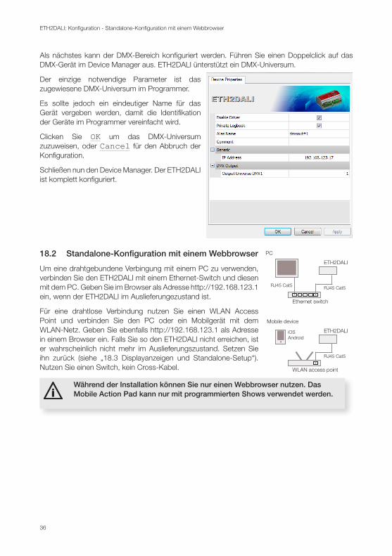
Als nächstes kann der DMX-Bereich konfiguriert werden. Führen Sie einen Doppelclick auf das DMX-Gerät im Device Manager aus. ETH2DALI ünterstützt ein DMX-Universum.
Der einzige notwendige Parameter ist das zugewiesene DMX-Universum im Programmer.
Es sollte jedoch ein eindeutiger Name für das Gerät vergeben werden, damit die Identifikation der Geräte im Programmer vereinfacht wird.
Clicken Sie OK um das DMX-Universum zuzuweisen, oder Cancel für den Abbruch der Konfiguration.
Schließen nun den Device Manager. Der ETH2DALI ist komplett konfiguriert.
18.2 Standalone-Konfiguration mit einem Webbrowser PC
Ethernet switch
ETH2DALI
RJ45 Cat5RJ45 Cat5
Mobile device
WLAN access point
ETH2DALI
RJ45 Cat5
iOSAndroid
Um eine drahtgebundene Verbingung mit einem PC zu verwenden, verbinden Sie den ETH2DALI mit einem Ethernet-Switch und diesen mit dem PC. Geben Sie im Browser als Adresse http://192.168.123.1 ein, wenn der ETH2DALI im Auslieferungezustand ist.
Für eine drahtlose Verbindung nutzen Sie einen WLAN Access Point und verbinden Sie den PC oder ein Mobilgerät mit dem WLAN-Netz. Geben Sie ebenfalls http://192.168.123.1 als Adresse in einem Browser ein. Falls Sie so den ETH2DALI nicht erreichen, ist er wahrscheinlich nicht mehr im Auslieferungszustand. Setzen Sie ihn zurück (siehe „18.3 Displayanzeigen und Standalone-Setup“). Nutzen Sie einen Switch, kein Cross-Kabel.
iWährend der Installation können Sie nur einen Webbrowser nutzen. Das Mobile Action Pad kann nur mit programmierten Shows verwendet werden.
37
ETH2DALI: Konfiguration - Standalone-Konfiguration mit einem Webbrowser
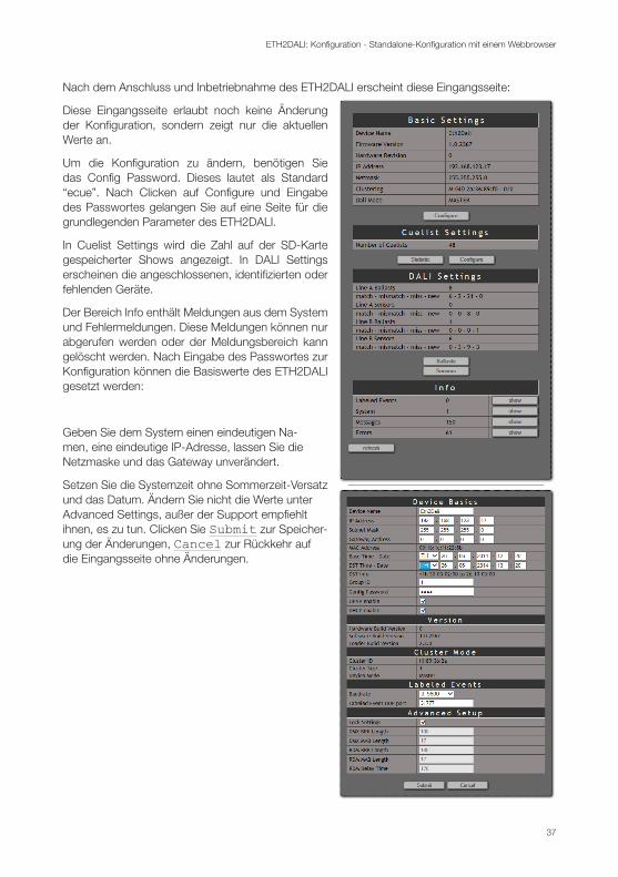
Nach dem Anschluss und Inbetriebnahme des ETH2DALI erscheint diese Eingangsseite:
Diese Eingangsseite erlaubt noch keine Änderung der Konfiguration, sondern zeigt nur die aktuellen Werte an.
Um die Konfiguration zu ändern, benötigen Sie das Config Password. Dieses lautet als Standard “ecue”. Nach Clicken auf Configure und Eingabe des Passwortes gelangen Sie auf eine Seite für die grundlegenden Parameter des ETH2DALI.
In Cuelist Settings wird die Zahl auf der SD-Karte gespeicherter Shows angezeigt. In DALI Settings erscheinen die angeschlossenen, identifizierten oder fehlenden Geräte.
Der Bereich Info enthält Meldungen aus dem System und Fehlermeldungen. Diese Meldungen können nur abgerufen werden oder der Meldungsbereich kann gelöscht werden. Nach Eingabe des Passwortes zur Konfiguration können die Basiswerte des ETH2DALI gesetzt werden:
Geben Sie dem System einen eindeutigen Na-men, eine eindeutige IP-Adresse, lassen Sie die Netzmaske und das Gateway unverändert.
Setzen Sie die Systemzeit ohne Sommerzeit-Versatz und das Datum. Ändern Sie nicht die Werte unter Advanced Settings, außer der Support empfiehlt ihnen, es zu tun. Clicken Sie Submit zur Speicher-ung der Änderungen, Cancel zur Rückkehr auf die Eingangsseite ohne Änderungen.

38
ETH2DALI: Konfiguration - Displayanzeigen und Standalone-Setup
Über die Eingangsseite sind auch Informationen zu den angeschlossenen und konfigurierten DALI-Geräte verfügbar. Clicken Sie dazu auf Ballasts oder Sensors.
Bedenken Sie, dass Änderungen der Min- und Max-Werte die Stimmung der Show verändern.
18.3 Displayanzeigen und Standalone-Setup
Nach dem Einschalten des ETH2DALI und Beginn des normalen Betriebes zeigt das Display zyklisch verschiedene Parameter und Werte des Systems an:
: e2d LOADERinit.... Bootloader aktiv.
ETH2DALIe:cue 2014 System-Identification.
ETH2DALIV1.0.32.10 Firmware-Version.
ETH2DALIscanning... Scannen der DALI-Linien, Ende der Boot-Phase.
ETH2DALI16:42:38 Gerätetyp und Systemzeit
IP:192.168.123.045 IP-Adresse
MASK:255.255.255.0 Netzmaske
MAC:0016:1c:f1:17:ab MAC-Adresse dieses ETH2DALI
Connection:192.168.123.10 Verbunden mit LAS-Server im Online-Modus oder
Connection:--- offline --- Keine Verbindung zum LAS-Server
39
ETH2DALI: Konfiguration - Standalone-Konfiguration mit Tastern und Display
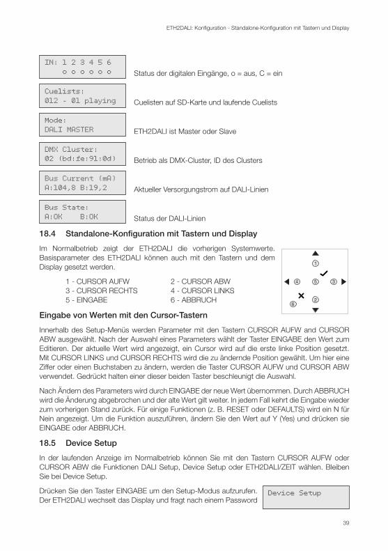
IN: 1 2 3 4 5 6 o o o o o o Status der digitalen Eingänge, o = aus, C = ein
Cuelists:012 - 01 playing Cuelisten auf SD-Karte und laufende Cuelists
Mode:DALI MASTER ETH2DALI ist Master oder Slave
DMX Cluster:02 (bd:fe:91:0d) Betrieb als DMX-Cluster, ID des Clusters
Bus Current (mA)A:104,8 B:19,2 Aktueller Versorgungstrom auf DALI-Linien
Bus State:A:OK B:OK Status der DALI-Linien
18.4 Standalone-Konfiguration mit Tastern und Display
1
2
34 5
6
Im Normalbetrieb zeigt der ETH2DALI die vorherigen Systemwerte. Basisparameter des ETH2DALI können auch mit den Tastern und dem Display gesetzt werden.
1 - CURSOR AUFW 2 - CURSOR ABW 3 - CURSOR RECHTS 4 - CURSOR LINKS 5 - EINGABE 6 - ABBRUCH
Eingabe von Werten mit den Cursor-Tastern
Innerhalb des Setup-Menüs werden Parameter mit den Tastern CURSOR AUFW and CURSOR ABW ausgewählt. Nach der Auswahl eines Parameters wählt der Taster EINGABE den Wert zum Editieren. Der aktuelle Wert wird angezeigt, ein Cursor wird auf die erste linke Position gesetzt. Mit CURSOR LINKS und CURSOR RECHTS wird die zu ändernde Position gewählt. Um hier eine Ziffer oder einen Buchstaben zu ändern, werden die Taster CURSOR AUFW und CURSOR ABW verwendet. Gedrückt halten einer dieser beiden Taster beschleunigt die Auswahl.
Nach Ändern des Parameters wird durch EINGABE der neue Wert übernommen. Durch ABBRUCH wird die Änderung abgebrochen und der alte Wert gilt weiter. In jedem Fall kehrt die Eingabe wieder zum vorherigen Stand zurück. Für einige Funktionen (z. B. RESET oder DEFAULTS) wird ein N für Nein angezeigt. Um die Funktion auszuführen, ändern Sie den Wert auf Y (Yes) und drücken sie EINGABE oder ABBRUCH.
18.5 Device Setup
In der laufenden Anzeige im Normalbetrieb können Sie mit den Tastern CURSOR AUFW oder CURSOR ABW die Funktionen DALI Setup, Device Setup oder ETH2DALI/ZEIT wählen. Bleiben Sie bei Device Setup.
Device SetupDrücken Sie den Taster EINGABE um den Setup-Modus aufzurufen. Der ETH2DALI wechselt das Display und fragt nach einem Password
40
ETH2DALI: Konfiguration - DALI-Setup
für die Änderungen. Das Standard-Password im Auslieferungszustand ist “ecue”, wenn es nicht in einem früheren Setup geändert wurde. Wählen Sie, wie zuvor beschrieben, die Buchstaben und drücken Sie EINGABE.
Daraufhin wird der Setup-Modus aktiv.
y Mit den Tastern CURSOR AUFW und CURSOR AUFW wird der zu ändernde Parameter ausgewählt.
y Mit EINGABE wird der Parameter zur Änderung aufgerufen.
y Nach der Änderung drücken Sie EINGABE zur Speicherung, ABBRUCH um die Änderungen zu verwerfen und zum vorherigen Status zurückzukehren.
Folgende Parameter können im Setup-Modus geändert werden:
IP Setzen der IP-Adresse MASK Setzen der Netzmaske Name Setzen des Gerätenamens RESET Zurücksetzen und Reboot, keine Änderung der Systemparameter Set to Defaults Zurücksetzen auf den Auslieferungszustand Enter Loader Starten des Bootloaders, z. B. für Firmware-Update Relay 1 Zustand des Relais 1 setzen Relay 2 Zustand des Relais 2 setzen Contrast Ändern des Display-Kontrastes
Während der Parameter-Auswahl kann mit dem Taster CURSOR LINKS zur Anzeige von System/Zeit zurück gekehrt werden.
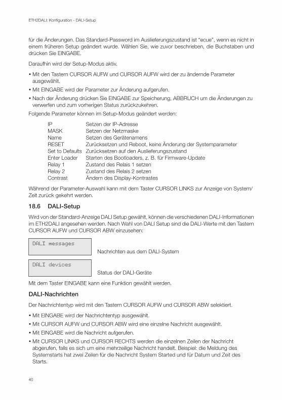
18.6 DALI-Setup
Wird von der Standard-Anzeige DALI Setup gewählt, können die verschiedenen DALI-Informationen im ETH2DALI angesehen werden. Nach Wahl von DALI Setup sind die DALI-Werte mit den Tastern CURSOR AUFW und CURSOR ABW einzusehen:
DALI messagesNachrichten aus dem DALI-System
DALI devicesStatus der DALI-Geräte
Mit dem Taster EINGABE kann eine Funktion gewählt werden.
DALI-Nachrichten
Der Nachrichtentyp wird mit den Tastern CURSOR AUFW und CURSOR ABW selektiert.
y Mit EINGABE wird der Nachrichtentyp ausgewählt.
y Mit CURSOR AUFW und CURSOR ABW wird eine einzelne Nachricht ausgewählt.
y Mit EINGABE wird die Nachricht aufgerufen.
y Mit CURSOR LINKS und CURSOR RECHTS werden die einzelnen Zeilen der Nachricht abgerufen, falls es sich um eine mehrzeilige Nachricht handelt. Beispiel: die Meldung des Systemstarts hat zwei Zeilen für die Nachricht System Started und für Datum und Zeit des Starts.

41
ETH2DALI: Test-Modus - DALI-Tests
y Mit ABBRUCH wird zur Nachrichtenauswahl zurück gekehrt.
y Ein weiteres Betätigen von ABBRUCH führt zur DALI-Setup Anzeige.
y System: Allgemeine System-Nachrichten
y Error: Fehlermeldung im Betrieb oder beim Start
y Log: Geräte-Meldungen
DALI-Geräte
Wird im vorherigen Schritt die Anzeige DALI Devices ausgewählt und EINGABE gedrückt, muss als erstes die DALI-Linie bestimmt werden.
y Drücken Sie den Taster CURSOR RECHTS.
y Drücken Sie CURSOR AUFW und CURSOR ABW um DALI A oder DALI B auszuwählen.
y Drücken Sie EINGABE für die Auswahl der DALI-Linie.
y Nach der Auswahl der DALI-Linie und erneutem Drücken von EINGABE erfolgt die Frage nach Sensors oder Ballasts.
y Drücken Sie EINGABE und wählen Sie Ballasts oder Sensors mit den Tasten CURSOR AUFW und CURSOR ABW.
y Drücken Sie wiederum EINGABE um den Gerätetyp zu wählen.
A.STD.12:statelost Das Gerät ist nicht verfügbar.
A.STD.54:statemismatch Die Kurzadresse des Gerätes ist falsch.
A.STD.54:stateempty Kein Gerät an dieser Adresse konfiguriert
Mit den Tastern CURSOR AUFW und CURSOR ABW kann das Gerät von 00 bis 63 pro Linie gewählt werden.
Der Taster ABBRUCH führt zur Auswahl des Gerätetyps zurück. Ein weiteres Drücken von ABBRUCH führt zur Auswahl Device Setup, DALI Setup oder Datum/Zeit zurück. Dies ist wieder der Normalbetrieb.
19 Test-Modus
19.1 DALI-Tests 1 2 3 4
5
6
8 9 10 11 12 13 14
7
Der ETH2DALI verfügt über einen Test-Modus für die angeschlossenen DALI-Linien und für die Relais. Diese Test werden mit den zwei Tastern auf der linken Seite initiiert (Pos. 6).
Der linke Taster ist für die DALI-Linie A und Releais 1 zuständig, der rechte für die DALI-Linie B und Relais 2. Drücken sie den entsprechenden Taster für den Start des Tests.
42
ETH2DALI: Test-Modus - Ausführen des DALI-Tests
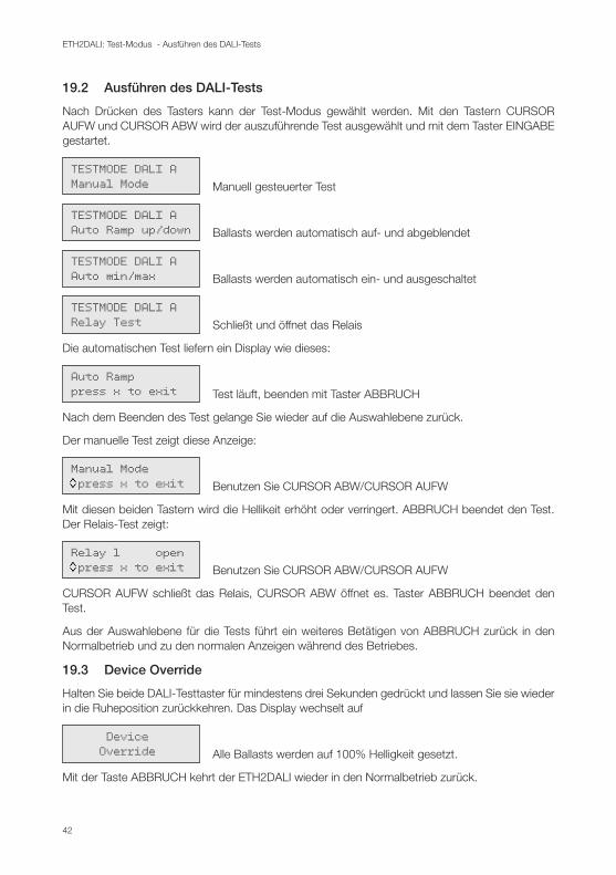
19.2 Ausführen des DALI-Tests
Nach Drücken des Tasters kann der Test-Modus gewählt werden. Mit den Tastern CURSOR AUFW und CURSOR ABW wird der auszuführende Test ausgewählt und mit dem Taster EINGABE gestartet.
TESTMODE DALI AManual Mode Manuell gesteuerter Test
TESTMODE DALI AAuto Ramp up/down Ballasts werden automatisch auf- und abgeblendet
TESTMODE DALI AAuto min/max Ballasts werden automatisch ein- und ausgeschaltet
TESTMODE DALI ARelay Test Schließt und öffnet das Relais
Die automatischen Test liefern ein Display wie dieses:
Auto Ramppress x to exit Test läuft, beenden mit Taster ABBRUCH
Nach dem Beenden des Test gelange Sie wieder auf die Auswahlebene zurück.
Der manuelle Test zeigt diese Anzeige:
Manual Mode press x to exit Benutzen Sie CURSOR ABW/CURSOR AUFW
Mit diesen beiden Tastern wird die Hellikeit erhöht oder verringert. ABBRUCH beendet den Test. Der Relais-Test zeigt:
Relay 1 open press x to exit Benutzen Sie CURSOR ABW/CURSOR AUFW
CURSOR AUFW schließt das Relais, CURSOR ABW öffnet es. Taster ABBRUCH beendet den Test.
Aus der Auswahlebene für die Tests führt ein weiteres Betätigen von ABBRUCH zurück in den Normalbetrieb und zu den normalen Anzeigen während des Betriebes.
19.3 Device Override
Halten Sie beide DALI-Testtaster für mindestens drei Sekunden gedrückt und lassen Sie sie wieder in die Ruheposition zurückkehren. Das Display wechselt auf
Device Override Alle Ballasts werden auf 100% Helligkeit gesetzt.
Mit der Taste ABBRUCH kehrt der ETH2DALI wieder in den Normalbetrieb zurück.
43
ETH2DALI: Firmware-Update - Fehleranzeigen auf Display
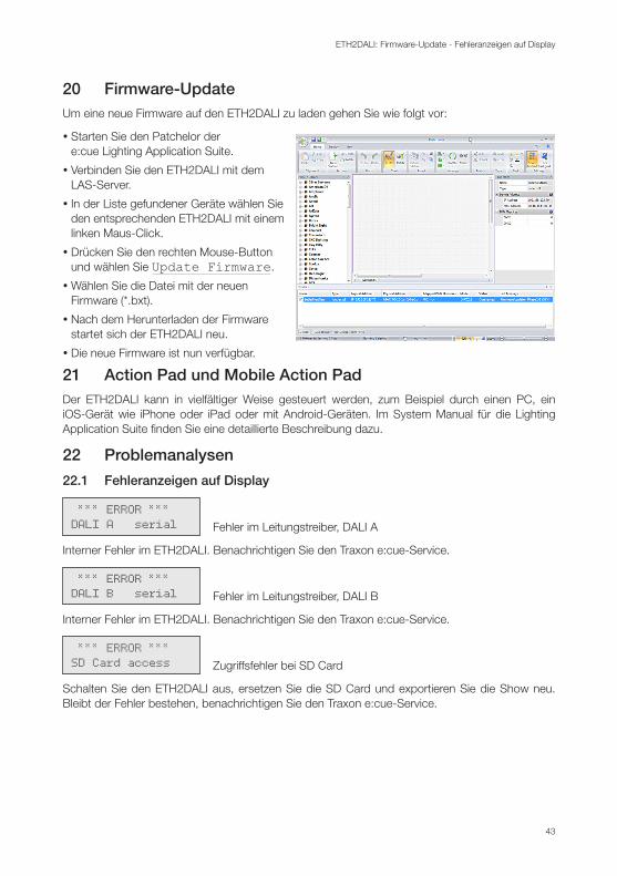
20 Firmware-UpdateUm eine neue Firmware auf den ETH2DALI zu laden gehen Sie wie folgt vor:
y Starten Sie den Patchelor der e:cue Lighting Application Suite.
y Verbinden Sie den ETH2DALI mit dem LAS-Server.
y In der Liste gefundener Geräte wählen Sie den entsprechenden ETH2DALI mit einem linken Maus-Click.
y Drücken Sie den rechten Mouse-Button und wählen Sie Update Firmware.
yWählen Sie die Datei mit der neuen Firmware (*.bxt).
y Nach dem Herunterladen der Firmware startet sich der ETH2DALI neu.
y Die neue Firmware ist nun verfügbar.
21 Action Pad und Mobile Action PadDer ETH2DALI kann in vielfältiger Weise gesteuert werden, zum Beispiel durch einen PC, ein iOS-Gerät wie iPhone oder iPad oder mit Android-Geräten. Im System Manual für die Lighting Application Suite finden Sie eine detaillierte Beschreibung dazu.
22 Problemanalysen
22.1 Fehleranzeigen auf Display
*** ERROR ***DALI A serial Fehler im Leitungstreiber, DALI A
Interner Fehler im ETH2DALI. Benachrichtigen Sie den Traxon e:cue-Service.
*** ERROR ***DALI B serial Fehler im Leitungstreiber, DALI B
Interner Fehler im ETH2DALI. Benachrichtigen Sie den Traxon e:cue-Service.
*** ERROR ***SD Card access Zugriffsfehler bei SD Card
Schalten Sie den ETH2DALI aus, ersetzen Sie die SD Card und exportieren Sie die Show neu. Bleibt der Fehler bestehen, benachrichtigen Sie den Traxon e:cue-Service.
44
ETH2DALI: Problemanalysen - Fehleranzeigen auf Display
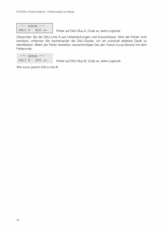
*** ERROR ***DALI A BUS xx Fehler auf DALI-Bus A, Code xx, siehe Logbook
Überprüfen Sie die DALI-Linie A auf Unterbrechungen und Kurzschlüsse. Wird der Fehler nicht behoben, entfernen Sie nacheinander die DALI-Geräte, um ein eventuell defektes Gerät zu identifizieren. Bleibt der Fehler bestehen, benachrichtigen Sie den Traxon e:cue-Service mit dem Fehlercode.
*** ERROR ***DALI B BUS xx Fehler auf DALI-Bus B, Code xx, siehe Logbook
Wie zuvor, jedoch DALI-Linie B.

45
ETH2DALI: Problemanalysen - Fehleranzeigen auf Display
Appendix

46
ETH2DALI: Dimensions/Abmessungen - Fehleranzeigen auf Display
23 Dimensions/AbmessungenAll dimensions in mm/Alle Abmessungen in mm


Downloads and more information at www.ecue.com