European Technical Approval - About Nelson · European Technical Approval ... The steel plate with...
55
NELSON Bolzenschweiß-Technik GmbH + Co. KG Postfach 4020, D-58272 Gevelsberg Flurstraße 7-19, D-58285 Gevelsberg Fon: 0 23 32 / 6 61 - 0 Fax: 0 23 32 / 6 61 - 1 65 www.nelson-europe.de European Technical Approval for NELSON-headed stuts TECHNICAL INFORMATION Deutsches Institut für Bautechnik ETA 03/0041 ETA 03/0042
Transcript of European Technical Approval - About Nelson · European Technical Approval ... The steel plate with...

NELSONBolzenschweiß-Technik GmbH + Co. KGPostfach 4020, D-58272 GevelsbergFlurstraße 7-19, D-58285 GevelsbergFon: 0 23 32 / 6 61 - 0Fax: 0 23 32 / 6 61 - 1 65www.nelson-europe.de
European Technical Approvalfor NELSON-headed stuts
TE
CH
NIC
AL
IN
FO
RM
AT
ION
Deutsches Institut für BautechnikETA 03/0041ETA 03/0042
Diese europäische technische Zulassung umfasst
This European Technical Approval contains
27 Seiten einschließlich 7 Anhänge 27 pages including 7 annexes
European Organisation for Technical Approvals Europäische Organisation für Technische Zulassungen
82833.03
Deutsches Institut für Bautechnik Anstalt des öffentlichen Rechts 10829 Berlin, Kolonnenstraße 30 L Tel.: +49(0)30-78730-0 Fax: +49(0)30-78730-320 e-Mail: [email protected]
Ermächtigtu n d n o t i f i z i e r t
gemäß Art ikel 10 derRichtlinie des Rates vom
21. Dezember 1988 zur An-gleichung der Rechts- undVerwaltungsvorschriften
d er M i tg l ie ds taa tenüber Bauprodukte
(89/106/EWG)
Mitglied der EOTA
European Technical Approval ETA-03/0041
Handelsbezeichnung Trade name
Nelson-Kopfbolzen aus Stahl
Zulassungsinhaber
Holder of approval Nelson Bolzenschweiß-Technik GmbH & Co. KG Flurstraße 7-19 58285 Gevelsberg
Zulassungsgegenstand und Verwendungszweck
Stahlplatte mit einbetonierten Nelson-Kopfbolzen aus Stahl
Generic type and use of construction product
Steel plate with cast-in Nelson-headed studs made of steel
Geltungsdauer vom Validity from
13. November 2003
bis to
13. November 2008
Herstellwerk 1 Herstellwerk 2 Herstellwerk
Manufacturing plant
Page 2 of European Technical Approval ETA-03/0041
82833.03
I LEGAL BASES AND GENERAL CONDITIONS
1 This European Technical Approval is issued by Deutsches Institut für Bautechnik in accordance with:
− Council Directive 89/106/EEC of 21 December 1988 on the approximation of laws, regulations and administrative provisions of Member States relating to construction products1, amended by the Council Directive 93/68/EEC of 22 July 19932;
− Gesetz über das Inverkehrbringen von und den freien Warenverkehr mit Bauprodukten zur Umsetzung der Richtlinie 89/106/EWG des Rates vom 21. Dezember 1988 zur Angleichung der Rechts- und Verwaltungsvorschriften der Mitgliedstaaten über Bauprodukte und anderer Rechtsakte der Europäischen Gemeinschaften (Bauproduktengesetz - BauPG) vom 28. April 19983;
− Common Procedural Rules for Requesting, Preparing and the Granting of European Technical Approvals set out in the Annex of Commission Decision 94/23/EC4;
2 Deutsches Institut für Bautechnik is authorized to check whether the provisions of this European Technical Approval are met. Checking may take place in the manufacturing plant. Nevertheless, the responsibility for the conformity of the products to the European Technical Approval and for their fitness for the intended use remains with the holder of the European Technical Approval.
3 This European Technical Approval is not to be transferred to manufacturers or agents of manufacturers other than those indicated on page 1, or manufacturing plants other than those indicated on page 1 of this European Technical Approval.
4 This European Technical Approval may be withdrawn by Deutsches Institut für Bautechnik, in particular after information by the Commission on the basis of Article 5 (1) of Council Directive 89/106/EEC.
5 Reproduction of this European Technical Approval including transmission by electronic means shall be in full. However, partial reproduction can be made with the written consent of the Deutsches Institut für Bautechnik. In this case partial reproduction has to be designated as such. Texts and drawings of advertising brochures shall not contradict or misuse the European Technical Approval.
6 The European Technical Approval is issued by the approval body in its official language. This version corresponds to the version circulated within EOTA. Translations into other languages have to be designated as such.
1 Official Journal of the European Communities N° L 40, 11.02.1989, p. 12 2 Official Journal of the European Communities N° L 220, 30.08.1993, p. 1 3 Bundesgesetzblatt I, p. 812, zuletzt geändert durch Gesetz ('last amended by law on') vom 15.12.2001,
Bundesgesetzblatt I, p. 3762 4 Official Journal of the European Communities N° L 17, 20.01.1994, p. 34
Page 3 of European Technical Approval ETA-03/0041
82833.03
II SPECIFIC CONDITIONS OF THE EUROPEAN TECHNICAL APPROVAL
1 Definition of product and intended use
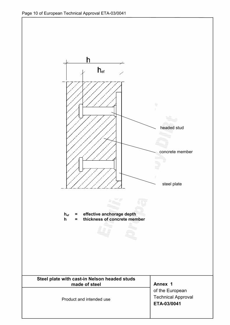
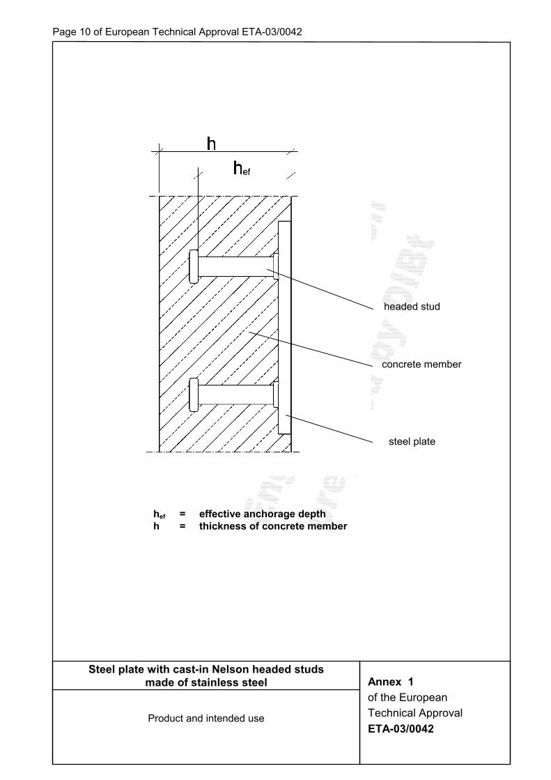
1.1 Definition of product The steel plate with cast-in Nelson-headed studs consists of one or more headed studs which are welded-on to a steel plate. The headed studs consist of steel with a diameter of the shaft of 10, 13, 16, 19, 22 and 25 mm. At the one end a head is formed by upsetting. The other end is prepared for drawn arc stud welding with ceramic ferrule or shielding gas (method 783 according to EN ISO 4063:2002-02). The product is surface-flush anchored in the concrete. For the installed product see figure given in Annex 1.
1.2 Intended use The steel plate with welded-on headed studs is intended for uses where requirements concerning mechanical resistance and stability as well as safety in use in the sense of the Essential Requirements ER1 and ER4 of the Directive 89/106/EEC shall be satisfied and where failure of the anchorage may cause risk to human life and health and/or lead to considerable economic consequences. Regarding the requirements concerning safety in case of fire (ER 2) it is assumed that the construction product meets the requirements of class A1 in relation to reaction to fire in accordance with the stipulations of the Commission decision 96/603/EC, amended by 200/605/EC. If the fire resistance is relevant then the fire resistance of the concrete member in which the construction product is anchored is to be tested according to test method provided in order to be classified according to prEN 13 501-2. The steel plate with welded-on headed studs is to be used for the anchorage under static or quasi static actions as well as under not predominantly static actions (fatigue actions) in reinforced normal concrete of the minimum strength class C 20/25 according to EN 206-1:2000-07. The construction product may be anchored in cracked and non-cracked concrete. The anchorage is admissible with single studs or groups of studs, which consist of two up to nine headed studs. The construction product can be stressed by a tensile load, shear load or a combination of tensile and shear loads. The steel plate with the welded-on headed studs is anchored in the concrete surface-flush. Other steel components may be welded-on to the steel plate. The steel plate from steel according to EN 10 025 with welded-on headed studs from steel S235J2G3+C450 according to EN 10 025 may only be used in concrete subject to dry internal conditions. The provisions made in this European Technical Approval are based on an assumed intended working life of the product of 50 years. The indications given on the working life cannot be interpreted as a guarantee given by the producer, but are to be regarded only as a means for choosing the right products in relation to the expected economically reasonable working life of the works.
Page 4 of European Technical Approval ETA-03/0041
82833.03
2 Characteristics of the product and method of verification
2.1 Characteristics of the product
2.1.1 General The characteristic material values, dimensions and tolerances of the product not indicated in
the Annexes shall correspond to respective values laid down in the technical documentation5 of this European Technical Approval.
The characteristic values for the design calculation of the anchorage are given in Annexes 4 to 6.
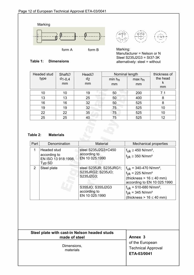
2.1.2 Headed stud The headed studs made from steel according to EN ISO 13 918-1998-10 "Studs and ceramic ferrules for arc stud welding" shall correspond to the materials, mechanical properties and dimensions given in Table 1 and 2, Annex 3. It is also permissible to use two headed studs welded one on top of the other by arc stud welding (see Annex 2). A padded ring is to be placed under the head of the first stud. The padded ring is to be secured in its position to make a permanent compression of ≥ 5 mm possible. The padded ring can be made, for example, of technical felt or cellular rubber. The external diameter of the padded ring shall exceed the head diameter and the inside diameter shall be less than the shaft diameter. The padded ring shall prevent a contact of the lower head at the concrete and a transmission of loads by the lower stud head.
2.1.3 Steel plate The steel plates, on which headed studs of steel S235J2G3+C450 according to Table 2, Annex 3 will be welded, shall consist of the materials S235JR, S235JRG1, S235JRG2, S235JO, S235J2G3, S355JO or S355J2G3 according to Table 2 Annex 3.
Because of the stress of the steel plate in the direction of the thickness a possibly not homogeneous structure of the steel plate in this direction shall be taken into account. At the same time the risk of lamellar tearing as well as lamellar imperfections in the steel plate shall be paid attention to.
For not predominantly static loads ultrasonic tested steel plates shall be used. 2.1.4 Welded joint
The headed studs shall be welded to the steel plate by means of drawn arc stud welding with ceramic ferrules or shielding gas in accordance with EN ISO 14555:1998. Welding of the headed studs via arc stud welding may be performed in the manufacturing plant or on the construction site. For the safeguarding of the quality assurance of the welded connection the provisions of EN ISO 14 555:1998 "Welding – Arc stud welding of metallic materials" and EN 729 "Quality requirements for welding – Fusion welding of metallic materials" shall apply for the executing company.
2.1.5 Marking The headed stud is identified according to the diameter of shaft and the nominal length of the
headed stud, e.g. 16/75. Each headed stud is marked with the identifying mark of the producer and the material according to Annex 3.
5 The technical documentation for this European Technical Approval is deposited at Deutsches Institut für Bautechnik
and, as far as relevant for the tasks of the approved bodies involved in the attestation of conformity procedure, is handed over to the approved bodies.
Page 5 of European Technical Approval ETA-03/0041
82833.03
2.2 Methods of verification
2.2.1 General The assessment of the fitness of the product for the intended use with regard to the
requirements of mechanical resistance and stability as well as safety in use in the sense of the Essential Requirements 1 and 4 was performed based on the ETAG 001 "Guideline for European Technical Approval of Metal Anchors for Use in Concrete" and the tests carried out.
2.2.2 Tests carried out The following tests were carried out for determination the characteristic resistance of the headed stud under different conditions. 1. Tests for determination of the steel resistance under tension load 2. Concrete cone failure, centric tension tests with single fastening without influence of
spacing and edge distance. 3. Blow-out failure, centric tension tests with single fastening; member edge c1 = 60 mm.
2.2.3 Calculated verifications
2.2.3.1 Basic values for the characteristic resistance under tension load (1) Steel failure
The characteristic resistance NRk,s for the cross section of the shaft is determined according to Annex C, clause 5.2.2.2 of ETAG 001 and proved by the test series 1, clause 2.2.2. The characteristic resistance in case of steel failure is given in Table 4 Annex 5. (2) Pull-out failure
The characteristic resistance NRk,p in case of failure by pull-out is given in Table 4 Annex 5. (3) Concrete cone failure
The test values (mean values) resulting from test series 2 of clause 2.2.2 prove the calculation values with reference to ETAG 001. The characteristic resistance NRk,c in case of concrete cone failure is determined according to Annex 7 clause 3.3. (4) Blow out failure The test values (mean values) resulting from test series 3 of clause 2.2.2 prove the calculation values with reference to ETAG 001. The characteristic resistance NRk,cb in case of blow out failure is determined according to Annex 7 clause 3.4. (5) Splitting failure due to loading
The required cross section of the minimum reinforcement shall be determined according to Annex 7 clause 3.5. (6) Characteristic resistance of hanger reinforcement under tension load
The characteristic resistance NRk,h of a bar of the hanger reinforcement depending on the nominal length of the headed stud (hn) and the anchorage length (lV,R) of the hanger reinforcement is given in Table 5 Annex 5.
2.2.3.2 Basic values for the characteristic resistance under shear load (1) Steel failure without lever arm
The characteristic resistance VRk,s for the cross section of the shaft was determined with reference to Annex C of ETAG 001. The α-value is 0.6 . The characteristic resistance in case of steel failure is given in Table 7 Annex 6. (2) Pry-out failure (concrete pry-out failure at the side opposite to the load direction) The characteristic resistance VRk,cp shall be determined with reference to Annex C clause 5.2.3.3 of ETAG 001 and according to Annex 7 clause 4.2.
Page 6 of European Technical Approval ETA-03/0041
82833.03
(3) Concrete edge failure The characteristic resistance VRk,c in case of concrete edge failure under shear load is determined with reference to Annex C clause 5.2.3.4 of ETAG 001 and according to Annex 7 clause 4.3. (4) Characteristic resistance of hanger reinforcement under shear load The characteristic resistance VRk,h of a bar of the hanger reinforcement with the corresponding anchorage length IV,R is given in Table 8 Annex 6.
3 Attestation of conformity of the product and CE marking
3.1 System of attestation of conformity The system of attestation of conformity 2(i) (referred to as System 1) according to Council Directive 89/106/EEC Annex III laid down by the European Commission provides: (a) tasks for the manufacturer (1) factory production control; (2) further testing of samples taken at the factory by the manufacturer in accordance with a prescribed test plan; (b) tasks for the approved body (3) initial type-testing of the product; (4) initial inspection of factory and of factory production control; (5) continuous surveillance, assessment and approval of factory production control.
3.2 Responsibility
3.2.1 Tasks for the manufacturer; factory production control The manufacturer has a factory production control system in the plant and exercises
permanent internal control of production. All the elements, requirements and provisions adopted by the manufacturer are documented in a systematic manner in the form of written policies and procedures. The factory production control system ensures that the product is in conformity with this European Technical Approval.
The manufacturer shall only use raw materials supplied with the relevant inspection documents as laid down in the prescribed test plan6. The incoming raw materials shall be subject to controls and tests by the manufacturer before acceptance. The check shall include control of inspection documents (comparison with nominal values) presented by the manufacturer of the raw materials by inspecting the dimensions and determination of the material properties. The material properties (tensile strength) of the raw materials of the headed stud are to be determined. The dimensions on the manufactured components of the product are to be checked. The required verifications and requirements for drawn arc stud welding according to EN ISO 14555:1998 shall be fulfilled.
The frequency of controls and tests conducted during production is laid down in the prescribed test plan6 taking account of the manufacturing process of the product.
6 The prescribed test plan has been deposited at the Deutsches Institut für Bautechnik and is handed over only to the
approved bodies involved in the conformity attestation procedure.
Page 7 of European Technical Approval ETA-03/0041
82833.03
The results of the factory production control are recorded and evaluated. The records include at least the following information: - designation of the product, the basic materials and the components; - type of control or testing; - date of manufacture of the product and date of testing of the product or of the basic
materials and components; - results of control and testing and, if appropriate, comparison with the requirements; - signature of person responsible for the factory production control.
The records shall be presented to the inspection body involved in the continuous surveillance. On request they shall be presented to Deutsches Institut für Bautechnik.
Details of extent, nature and frequency of testing and controls to be performed within the factory production control shall correspond to the prescribed test plan6, which is part of the technical documentation of this European Technical Approval.
3.2.2 Tasks for the approved bodies
3.2.2.1 Initial type-testing of the product For initial type-testing the results of the tests performed as part of the assessment for the
European Technical Approval shall be used unless there are changes in the production line or plant. In such cases the necessary initial type-testing has to be agreed between the Deutsches Institut für Bautechnik and the approved bodies involved.
3.2.2.2 Initial inspection of factory and of factory production control The approved body shall ascertain that, in accordance with the prescribed test plan6, the
factory, in particular the staff and equipment, and the factory production control are suitable to ensure a continuous and orderly manufacturing of the product with the specifications mentioned in 2.1 as well as in the Annexes to the European Technical Approval.
3.2.2.3 Continuous surveillance The approved body shall visit the factory at least once a year for surveillance. It has to be
verified that the system of factory production control and the specified manufacturing process are maintained taking account of the prescribed test plan6.
Continuous surveillance and assessment of factory production control have to be performed according to the prescribed test plan6.
The results of product certification and continuous surveillance shall be made available on demand by the certification body or inspection body, respectively, to the Deutsches Institut für Bautechnik. In cases where the provisions of the European Technical Approval and the prescribed test plan6 are no longer fulfilled the conformity certificate shall be withdrawn.
3.3 CE marking The CE marking shall be affixed to each packaging or on the accompanying documents of the product. In addition to the initials "CE" the following information shall be given: - identification number of the certification body; - name or identifying mark of producer and manufacturing plant; - the last two digits of the year in which the CE marking was affixed; - number of the EC certificate of conformity; - number of the European Technical Approval; - name of the product.

Page 8 of European Technical Approval ETA-03/0041
82833.03
4 Assumptions under which the fitness of the product for the intended use was favourably assessed
4.1 Manufacturing The product is manufactured in accordance with the provisions of the European Technical
Approval using the manufacturing process as identified in the inspection of the plant by the Deutsches Institut für Bautechnik and the approved body and laid down in the technical documentation.
4.2 Installation
4.2.1 Design of anchorages The fitness of the product for the intended use is given under the following condition:
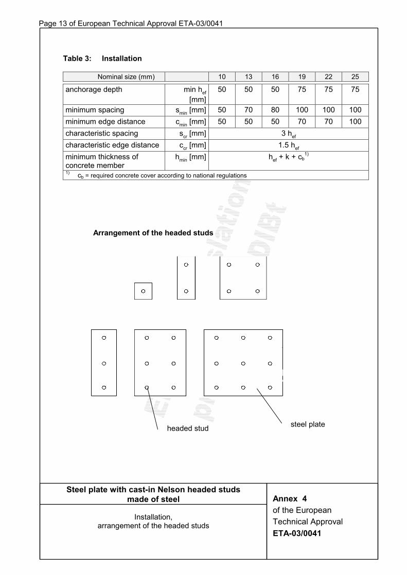
The design of the anchorage is based on the design method in Annex 7 under the responsibility of an engineer experienced in anchorages and concrete building. Verifiable calculation notes and drawings are prepared taking account of the loads to be anchored. The transfer of the loads to be anchored in the concrete member is verified. Single studs or groups of studs consisting of two to nine headed studs according to Annex 4 are used. Headed studs of the same diameter and length are used only in a group of headed studs. The position of the product is indicated on the design drawings (e.g. position of the headed studs towards the reinforcement or the supports).
Because of the stress of the steel plate in the direction of the thickness a possibly not homogeneous structure of the steel plate in this direction shall be taken into account. At the same time the risk of lamellar tearing as well as lamellar imperfections in the steel plate shall be paid attention to.
For not predominantly static loads ultrasonic tested steel plates shall be used. On the anchorage of not predominantly static action the following characteristic range of steel stresses may not be exceeded: - tensile load ∆σ = 100 N/mm² - shear loading ∆τ = 35 N/mm² - hanger reinforcement ∆σ = 60 N/mm² The partial safety factor for fatigue strength may be taken with γMf = 1.35 .
4.2.2 Installation The fitness of the anchorage for the intended use can be assumed only, if the following
installation conditions are kept: - Installation carried out by appropriately qualified personnel and under the supervision
of the person responsible for technical matters on site. - Use of the product only as supplied by the manufacturer without exchanging the
components. - Installation in accordance with the manufacturer's specifications and the design
drawings with exact position, dimensions of the steel plate and size and length of the headed studs.
- The anchorage shall be fixed to the formwork or auxiliary constructions in a way that no movement of the product will occur during placing of reinforcement or during placing and compacting of the concrete.
- The concrete under the head of the headed stud shall be properly compacted (no cavities). For large fixtures (steel plate > 400 mm x 400 mm) vent openings shall be provided. These shall be specified in the installation instructions.
- Observation of the prescribed values of installations.

Page 9 of European Technical Approval ETA-03/0041
82833.03
Welding-on of the intended and designed steel components to the cast-in construction product may only be performed by companies meeting the corresponding quality requirements for welding according to EN 729 "Quality requirements for welding – Fusion welding of metallic materials".
4.2.3 Responsibility of the manufacturer It is in the responsibility of the manufacturer to ensure that the information on the specific conditions according to 1 and 2 including Annexes referred to and 4.2.1 and 4.2.2 is given to those who are concerned. This information may be made by reproduction of the respective parts of the European Technical Approval. In addition all installation data shall be shown clearly on the package and/or on an enclosed instruction sheet, preferably using illustration(s). The minimum data required are: - Dimensions of the steel plate, - diameter of the headed studs, - length of the headed studs, - number of the headed studs, - material of the steel plate, - material of the headed studs and - details on the installation of procedure, preferably by using illustrations. All data shall be presented in a clear and explicit form.
Prof. Dr.-Ing. Bossenmayer Beglaubigt: Reimold
Page 10 of European Technical Approval ETA-03/0041
Steel plate with cast-in Nelson headed studs made of steel
Product and intended use
Annex 1 of the European Technical Approval ETA-03/0041
steel plate
concrete member
headed stud
hef = effective anchorage depth h = thickness of concrete member
Page 11 of European Technical Approval ETA-03/0041
d1 = diameter of shaft d2 = diameter of head hef = effective anchorage depth hn = nominal length of the headed stud (after welding) k = thickness of the head t = thickness of the steel plate αααα = 90°
Steel plate with cast-in Nelson headed studs made of steel
Details of the construction product
Annex 2 of the European Technical Approval ETA-03/0041
1 headed stud
2 steel plate
1 headed studs
padded ring
2 steel plate
hef = hn – k (if the theoretic cone meets the steel plate at angle of ~ 30°)
hef = hn – k +t
hef = hn1 + hn2 - k2 + t
α
Page 12 of European Technical Approval ETA-03/0041
Table 1: Dimensions
Nominal length Headed stud type
Shaft∅ d1-0,4
mm
Head∅ d2
mm min hn
mm max hn
mm
thickness of the head
k mm
10 10 19 50 200 7.1 13 13 25 50 400 8 16 16 32 50 525 8 19 19 32 75 525 10 22 22 35 75 525 10 25 25 40 75 525 12
Table 2: Materials
Part Denomination Material Mechanical properties
1 Headed stud according to EN ISO 13 918:1998, Typ:SD
steel S235J2G3+C450 according to EN 10 025:1990
fuk ≥ 450 N/mm², fyk ≥ 350 N/mm²
steel S235JR; S235JRG1; S235JRG2; S235JO; S235J2G3;
fuk = 340-470 N/mm², fyk = 225 N/mm² (thickness > 16 ≤ 40 mm) according to EN 10 025:1990
2 Steel plate
S355JO; S355J2G3 according to EN 10 025:1990
fuk = 510-680 N/mm², fyk = 345 N/mm² (thickness > 16 ≤ 40 mm)
Steel plate with cast-in Nelson headed studs made of steel
Dimensions,
materials
Annex 3 of the European Technical Approval ETA-03/0041
Marking
form A form B Marking: Manufacturer = Nelson or N Steel S235J2G3 = St37-3K alternatively: steel = without
Page 13 of European Technical Approval ETA-03/0041
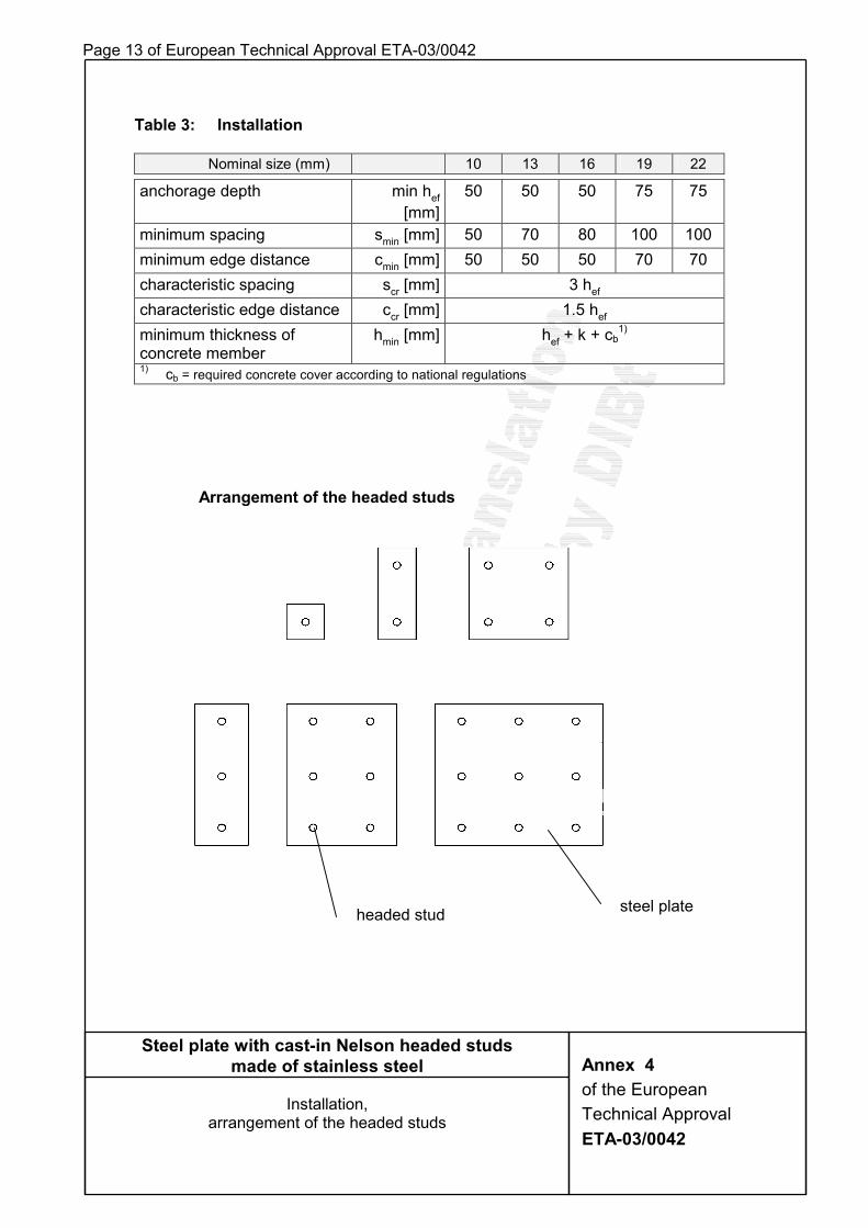
Table 3: Installation
Nominal size (mm) 10 13 16 19 22 25
anchorage depth min hef [mm]
50 50 50 75 75 75
minimum spacing smin [mm] 50 70 80 100 100 100 minimum edge distance cmin [mm] 50 50 50 70 70 100 characteristic spacing scr [mm] 3 hef characteristic edge distance ccr [mm] 1.5 hef minimum thickness of concrete member
hmin [mm] hef + k + cb1)
1) cb = required concrete cover according to national regulations
Steel plate with cast-in Nelson headed studs made of steel
Installation,
arrangement of the headed studs
Annex 4 of the European Technical Approval ETA-03/0041
Arrangement of the headed studs
headed stud steel plate
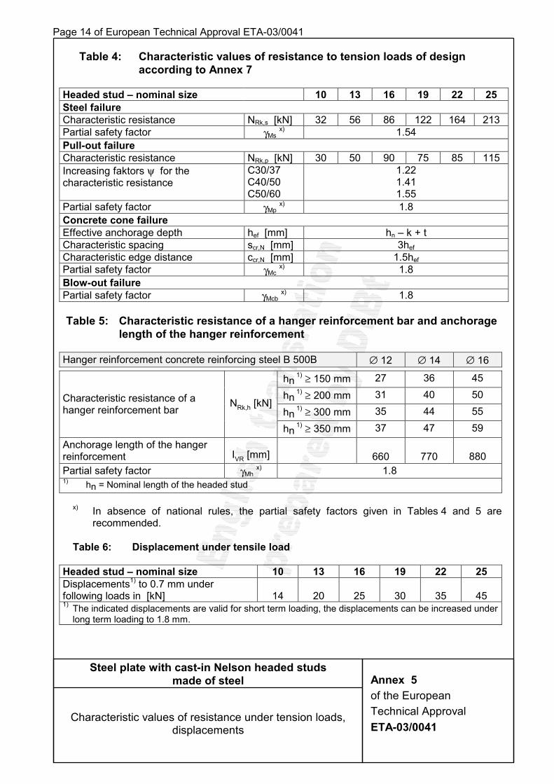
Page 14 of European Technical Approval ETA-03/0041 Table 4: Characteristic values of resistance to tension loads of design
according to Annex 7
Headed stud – nominal size 10 13 16 19 22 25 Steel failure Characteristic resistance NRk,s [kN] 32 56 86 122 164 213 Partial safety factor γMs x) 1.54 Pull-out failure Characteristic resistance NRk,p [kN] 30 50 90 75 85 115 Increasing faktors ψ for the characteristic resistance
C30/37 C40/50 C50/60
1.22 1.41 1.55
Partial safety factor γMp x) 1.8 Concrete cone failure Effective anchorage depth hef [mm] hn – k + t Characteristic spacing scr,N [mm] 3hef Characteristic edge distance ccr,N [mm] 1.5hef Partial safety factor γMc x) 1.8 Blow-out failure Partial safety factor γMcb x) 1.8
Table 5: Characteristic resistance of a hanger reinforcement bar and anchorage
length of the hanger reinforcement
Hanger reinforcement concrete reinforcing steel B 500B ∅ 12 ∅ 14 ∅ 16
hn 1) ≥ 150 mm 27 36 45
hn 1) ≥ 200 mm 31 40 50
hn 1) ≥ 300 mm 35 44 55
Characteristic resistance of a hanger reinforcement bar NRk,h [kN]
hn 1) ≥ 350 mm 37 47 59
Anchorage length of the hanger reinforcement IVR [mm] 660 770 880 Partial safety factor γMh x) 1.8 1) hn = Nominal length of the headed stud
x) In absence of national rules, the partial safety factors given in Tables 4 and 5 are
recommended. Table 6: Displacement under tensile load
Headed stud – nominal size 10 13 16 19 22 25 Displacements1) to 0.7 mm under following loads in [kN]
14
20
25
30
35
45
1) The indicated displacements are valid for short term loading, the displacements can be increased under long term loading to 1.8 mm.
Steel plate with cast-in Nelson headed studs made of steel
Characteristic values of resistance under tension loads, displacements
Annex 5 of the European Technical Approval ETA-03/0041
Page 15 of European Technical Approval ETA-03/0041
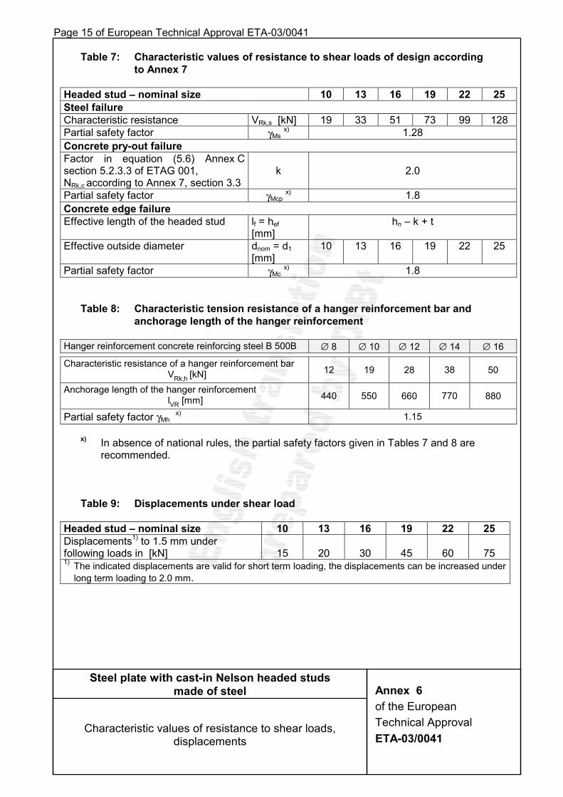
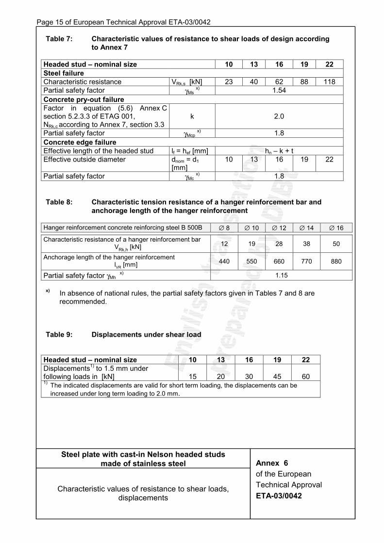
Table 7: Characteristic values of resistance to shear loads of design according
to Annex 7
Headed stud – nominal size 10 13 16 19 22 25 Steel failure Characteristic resistance VRk,s [kN] 19 33 51 73 99 128 Partial safety factor γMs x) 1.28 Concrete pry-out failure Factor in equation (5.6) Annex C section 5.2.3.3 of ETAG 001, NRk,c according to Annex 7, section 3.3
k
2.0
Partial safety factor γMcp x) 1.8 Concrete edge failure Effective length of the headed stud lf = hef
[mm] hn – k + t
Effective outside diameter dnom = d1 [mm]
10 13 16 19 22 25
Partial safety factor γMc x) 1.8
Table 8: Characteristic tension resistance of a hanger reinforcement bar and anchorage length of the hanger reinforcement
Hanger reinforcement concrete reinforcing steel B 500B ∅ 8 ∅ 10 ∅ 12 ∅ 14 ∅ 16
Characteristic resistance of a hanger reinforcement bar VRk,h [kN] 12 19 28 38 50
Anchorage length of the hanger reinforcement lVR [mm] 440 550 660 770 880
Partial safety factor γMh x) 1.15 x) In absence of national rules, the partial safety factors given in Tables 7 and 8 are
recommended.
Table 9: Displacements under shear load
Headed stud – nominal size 10 13 16 19 22 25 Displacements1) to 1.5 mm under following loads in [kN]
15
20
30
45
60
75
1) The indicated displacements are valid for short term loading, the displacements can be increased under long term loading to 2.0 mm.
Steel plate with cast-in Nelson headed studs made of steel
Characteristic values of resistance to shear loads, displacements
Annex 6 of the European Technical Approval ETA-03/0041
Page 16 of European Technical Approval ETA-03/0041
Design of anchorage of the headed studs in concrete Table of contents
1 General
2 Required verifications
3 Characteristic resistance under tension load 3.1 Steel failure
3.2 Pull-out failure
3.3 Concrete cone failure
3.4 Blow-out failure
3.5 Splitting failure
3.6 Characteristic resistance of a hanger reinforcement under tension load
4 Characteristic resistance under shear load 4.1 Steel failure
4.2 Concrete pry-out failure
4.3 Concrete edge failure
4.4 Characteristic resistance of a hanger reinforcement under shear load
5 Resistance of concrete member
Steel plate with cast-in Nelson headed studs made of steel
Design of anchorage of the headed studs in concrete
Annex 7 of the European Technical Approval ETA-03/0041
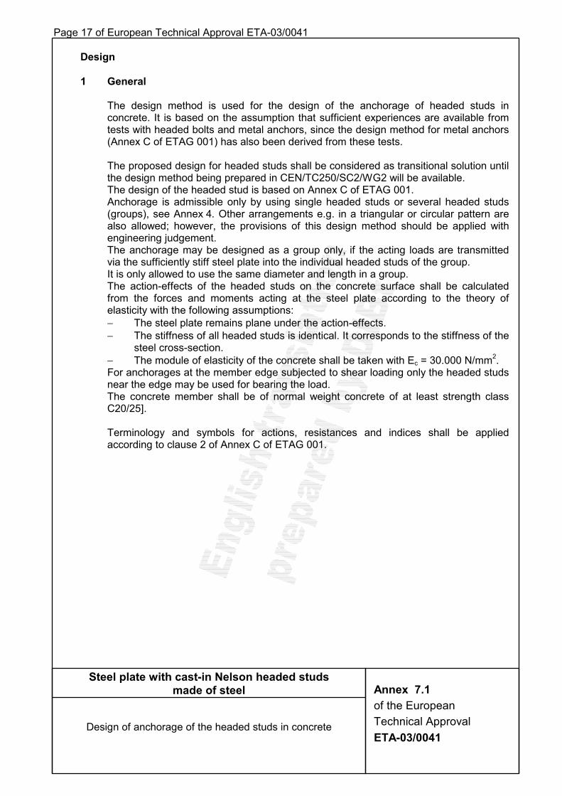
Page 17 of European Technical Approval ETA-03/0041 Design 1 General The design method is used for the design of the anchorage of headed studs in
concrete. It is based on the assumption that sufficient experiences are available from tests with headed bolts and metal anchors, since the design method for metal anchors (Annex C of ETAG 001) has also been derived from these tests.
The proposed design for headed studs shall be considered as transitional solution until
the design method being prepared in CEN/TC250/SC2/WG2 will be available. The design of the headed stud is based on Annex C of ETAG 001. Anchorage is admissible only by using single headed studs or several headed studs
(groups), see Annex 4. Other arrangements e.g. in a triangular or circular pattern are also allowed; however, the provisions of this design method should be applied with engineering judgement.
The anchorage may be designed as a group only, if the acting loads are transmitted via the sufficiently stiff steel plate into the individual headed studs of the group.
It is only allowed to use the same diameter and length in a group. The action-effects of the headed studs on the concrete surface shall be calculated
from the forces and moments acting at the steel plate according to the theory of elasticity with the following assumptions:
− The steel plate remains plane under the action-effects. − The stiffness of all headed studs is identical. It corresponds to the stiffness of the
steel cross-section. − The module of elasticity of the concrete shall be taken with Ec = 30.000 N/mm2. For anchorages at the member edge subjected to shear loading only the headed studs
near the edge may be used for bearing the load. The concrete member shall be of normal weight concrete of at least strength class
C20/25]. Terminology and symbols for actions, resistances and indices shall be applied
according to clause 2 of Annex C of ETAG 001.
Steel plate with cast-in Nelson headed studs made of steel
Design of anchorage of the headed studs in concrete
Annex 7.1 of the European Technical Approval ETA-03/0041

Page 18 of European Technical Approval ETA-03/0041 2 Required verifications The design of the headed studs shall be based on the safety concept with partial
safety factors according to Annex C, ETAG 001. The required verifications of the resistances are shown in Table 2.1 and 2.2.
Table 2.1: Required verifications for resistance to tension loading
Failure mode Single anchorage Groups
Steel failure (head stud) NSd ≤ NRk,s / γMs NSdh ≤ NRk,s / γMs
Pull-out failure NSd ≤ NRk,p / γMc NSdh ≤ NRk,p / γMc
Concrete cone failure without hanger reinforcement
NSd ≤ NRk,c / γMc NSdg ≤ NRk,c / γMc
Blow-out failure NSd ≤ NRk,cb / γMc NSdg ≤ NRk,cb / γMc
Hanger reinforcement
NSd ≤ NRk,h / γMh NSdh ≤ NRk,h / γMh Concrete cone failure
with hanger reinforcement Concrete cone NSk ≤ NRk,c / 1.3 NSk
g ≤ NRk,c / 1.3
Splitting failure Minimum reinforcement acc. to 3.5
Table 2.2: Required verifications for resistance to shear loading
Failure mode Single anchorage Groups Steel failure (head stud) VSd ≤ VRk,s / γMs VSd
h ≤ VRk,s / γMs Concrete pry-out failure VSd ≤ VRk,cp / γMc VSd
g ≤ VRk,cp / γMc Concrete edge failure 1) VSd ≤ VRk,c / γMc VSd
g ≤ VRk,c / γMc Resistance of hanger reinforcement with anchorages near the edge VSd ≤ VRk,h / γMh VSd
h ≤ VRk,h / γMh 1) This verification is not required, if there is a hanger reinforcement (see section 4.4).
In the case of a combined tension and shear loading the following Equation shall be observed:
(NSd/NRd)α + (VSd/VRd)α < 1 (1) The ratios NSd/NRd and VSd/VRd shall each be given the maximum value from the
individual failure modes. For the anchorages without hanger reinforcement or for anchorages with hanger
reinforcement for tension load and shear load the α-value in Equation (1) shall be taken with 1.5. Where either a hanger reinforcement for tension load (section 3.6) or a hanger reinforcement for shear loading at the edge (section 4.4) is taken into account for the design, the α-value shall be taken with 2/3.
Steel plate with cast-in Nelson headed studs made of steel
Design of anchorage of the headed studs in concrete
Annex 7.2 of the European Technical Approval ETA-03/0041
Page 19 of European Technical Approval ETA-03/0041
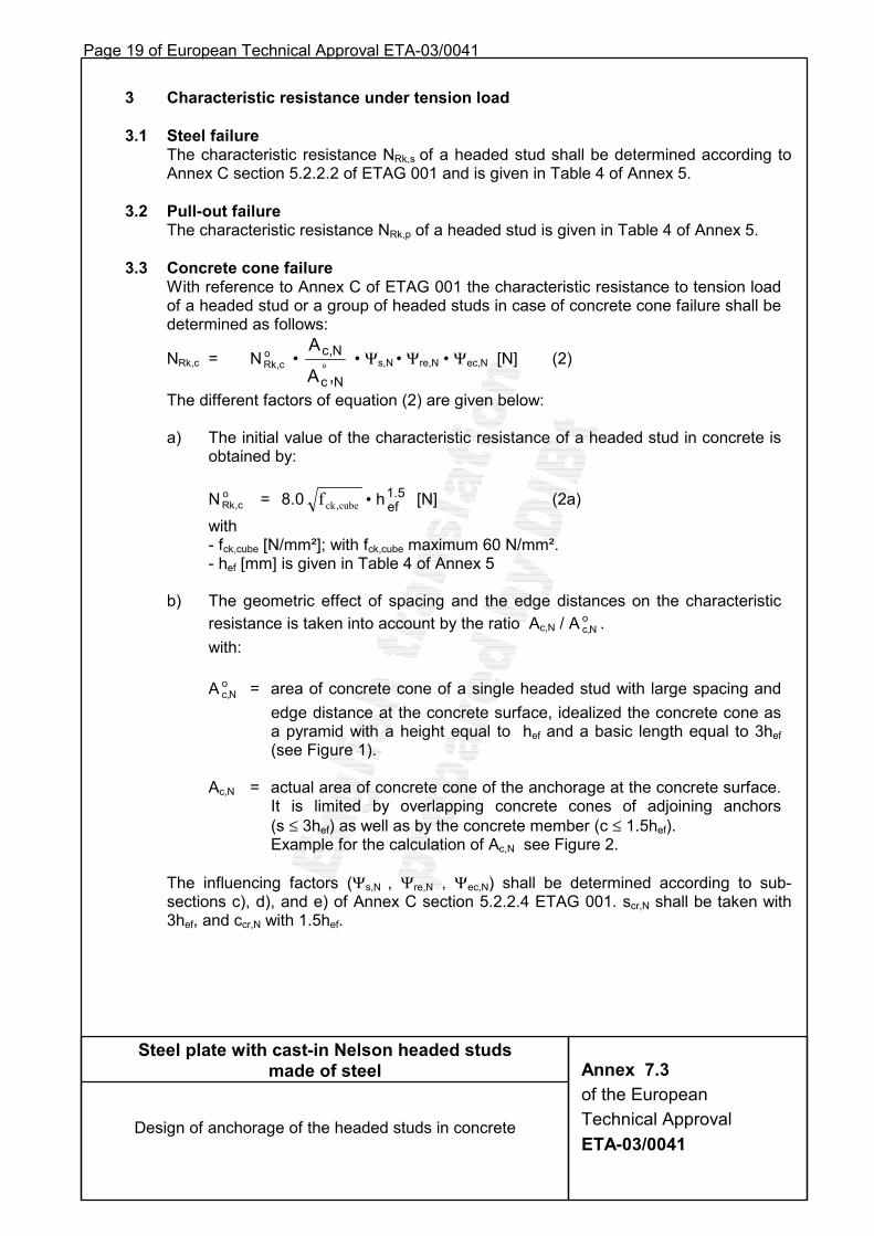
3 Characteristic resistance under tension load 3.1 Steel failure The characteristic resistance NRk,s of a headed stud shall be determined according to
Annex C section 5.2.2.2 of ETAG 001 and is given in Table 4 of Annex 5. 3.2 Pull-out failure The characteristic resistance NRk,p of a headed stud is given in Table 4 of Annex 5. 3.3 Concrete cone failure With reference to Annex C of ETAG 001 the characteristic resistance to tension load
of a headed stud or a group of headed studs in case of concrete cone failure shall be determined as follows:
NRk,c = N Rk co
, • Nc
N,c
,A
Ao • Ψs,N • Ψre,N • Ψec,N [N] (2)
The different factors of equation (2) are given below: a) The initial value of the characteristic resistance of a headed stud in concrete is
obtained by: N Rk c
o, = 8.0 cube,ckf • h 5.1
ef [N] (2a) with - fck,cube [N/mm²]; with fck,cube maximum 60 N/mm². - hef [mm] is given in Table 4 of Annex 5 b) The geometric effect of spacing and the edge distances on the characteristic
resistance is taken into account by the ratio Ac,N / A c,No .
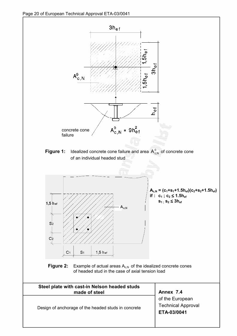
with: A c,N
o = area of concrete cone of a single headed stud with large spacing and edge distance at the concrete surface, idealized the concrete cone as a pyramid with a height equal to hef and a basic length equal to 3hef (see Figure 1).
Ac,N = actual area of concrete cone of the anchorage at the concrete surface.
It is limited by overlapping concrete cones of adjoining anchors (s ≤ 3hef) as well as by the concrete member (c ≤ 1.5hef).
Example for the calculation of Ac,N see Figure 2.
The influencing factors (Ψs,N , Ψre,N , Ψec,N) shall be determined according to sub-sections c), d), and e) of Annex C section 5.2.2.4 ETAG 001. scr,N shall be taken with 3hef, and ccr,N with 1.5hef.
Steel plate with cast-in Nelson headed studs made of steel
Design of anchorage of the headed studs in concrete
Annex 7.3 of the European Technical Approval ETA-03/0041
Page 20 of European Technical Approval ETA-03/0041
Steel plate with cast-in Nelson headed studs made of steel
Design of anchorage of the headed studs in concrete
Annex 7.4 of the European Technical Approval ETA-03/0041
Figure 1: Idealized concrete cone failure and area 0N,cA of concrete cone
of an individual headed stud
Ac,N = (c1+s1+1.5hef)(c2+s2+1.5hef) if : c1 ; c2 ≤≤≤≤ 1.5hef s1 ; s2 ≤≤≤≤ 3hef
Figure 2: Example of actual areas Ac,N of the idealized concrete cones of headed stud in the case of axial tension load
concrete cone failure
Page 21 of European Technical Approval ETA-03/0041
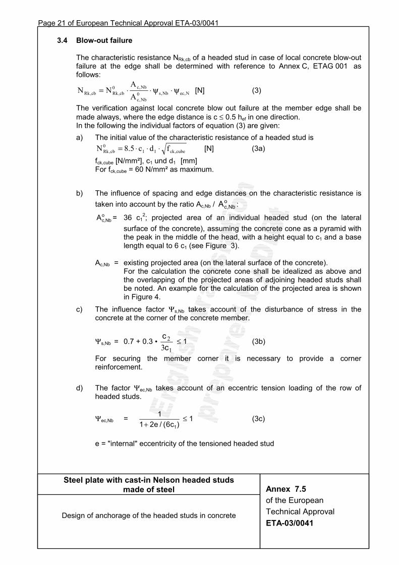
3.4 Blow-out failure The characteristic resistance NRk,cb of a headed stud in case of local concrete blow-out
failure at the edge shall be determined with reference to Annex C, ETAG 001 as follows:
N,ecNb,s0Nb,c
Nb,c0cb,Rkcb,Rk A
ANN ψ⋅ψ⋅⋅= [N] (3)
The verification against local concrete blow out failure at the member edge shall be made always, where the edge distance is c ≤ 0.5 hef in one direction. In the following the individual factors of equation (3) are given: a) The initial value of the characteristic resistance of a headed stud is
cube,ck110
cb,Rk fdc5.8N ⋅⋅⋅= [N] (3a) fck,cube [N/mm²], c1 und d1 [mm] For fck,cube = 60 N/mm² as maximum.
b) The influence of spacing and edge distances on the characteristic resistance is taken into account by the ratio Ac,Nb / o
Nb,cA :
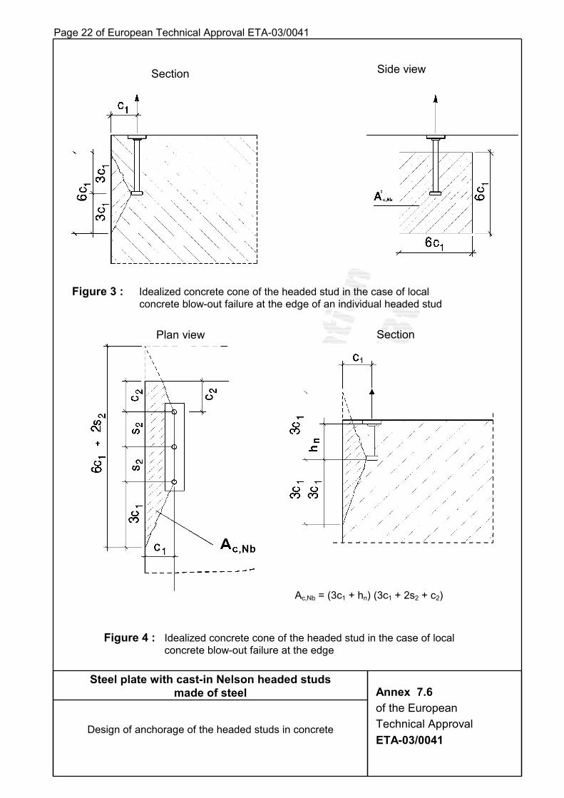
Ac,Nbo = 36 c1
2; projected area of an individual headed stud (on the lateral surface of the concrete), assuming the concrete cone as a pyramid with the peak in the middle of the head, with a height equal to c1 and a base length equal to 6 c1 (see Figure 3).
Ac,Nb = existing projected area (on the lateral surface of the concrete).
For the calculation the concrete cone shall be idealized as above and the overlapping of the projected areas of adjoining headed studs shall be noted. An example for the calculation of the projected area is shown in Figure 4.
c) The influence factor Ψs,Nb takes account of the disturbance of stress in the concrete at the corner of the concrete member.
Ψs,Nb = 0.7 + 0.3 • 1
23cc
≤ 1 (3b)
For securing the member corner it is necessary to provide a corner reinforcement.
d) The factor Ψec,Nb takes account of an eccentric tension loading of the row of
headed studs.
Ψec,Nb = 11 2e 6 1+ / ( )c
≤ 1 (3c)
e = "internal" eccentricity of the tensioned headed stud
Steel plate with cast-in Nelson headed studs made of steel
Design of anchorage of the headed studs in concrete
Annex 7.5 of the European Technical Approval ETA-03/0041
Page 22 of European Technical Approval ETA-03/0041
Figure 3 : Idealized concrete cone of the headed stud in the case of local concrete blow-out failure at the edge of an individual headed stud
Figure 4 : Idealized concrete cone of the headed stud in the case of local concrete blow-out failure at the edge
Section Side view
Plan view Section
Ac,Nb = (3c1 + hn) (3c1 + 2s2 + c2)
Steel plate with cast-in Nelson headed studs made of steel
Design of anchorage of the headed studs in concrete
Annex 7.6 of the European Technical Approval ETA-03/0041
Page 23 of European Technical Approval ETA-03/0041 3.5 Splitting failure
A minimum reinforcement with the following section AS shall exist in order to prevent a splitting of the concrete member:
AS erf = 0.5 •Mhyk
Sd/fN
γ� [mm²] (4)
�NSd = Sum of the tensile forces of the headed studs in tension under the design value of the actions [N]
fyk = Yield strength of reinforcement [N/mm²]
γMh = Partial safety factor for the reinforcement according to national rules; in the absence of such rules, the partial safety factor can be taken with 1.15 from EC 2.
This minimum reinforcement can be omitted, if there is at least one cross-wise reinforcement (B 500 B) ∅ 8/15 in the zone of the headed studs.
For slab- and plate-like members the reinforcement against splitting must be provided in both directions, i.e. in the case of members subjected mainly to tension the reinforcement shall be provided on both cross-sectional surfaces and in the case of members subjected mainly to bending on the side exposed to tension. It shall consist of at least three bars with a bar distance ≤ 150 mm and shall be anchored, outside the anchorage, with an anchorage depth according to national rules.
For linear structures the splitting reinforcement needs to be provided in one direction only. In the case of anchorages near the edge of members this reinforcement must be also provided as edge reinforcement with corresponding hanger reinforcement.
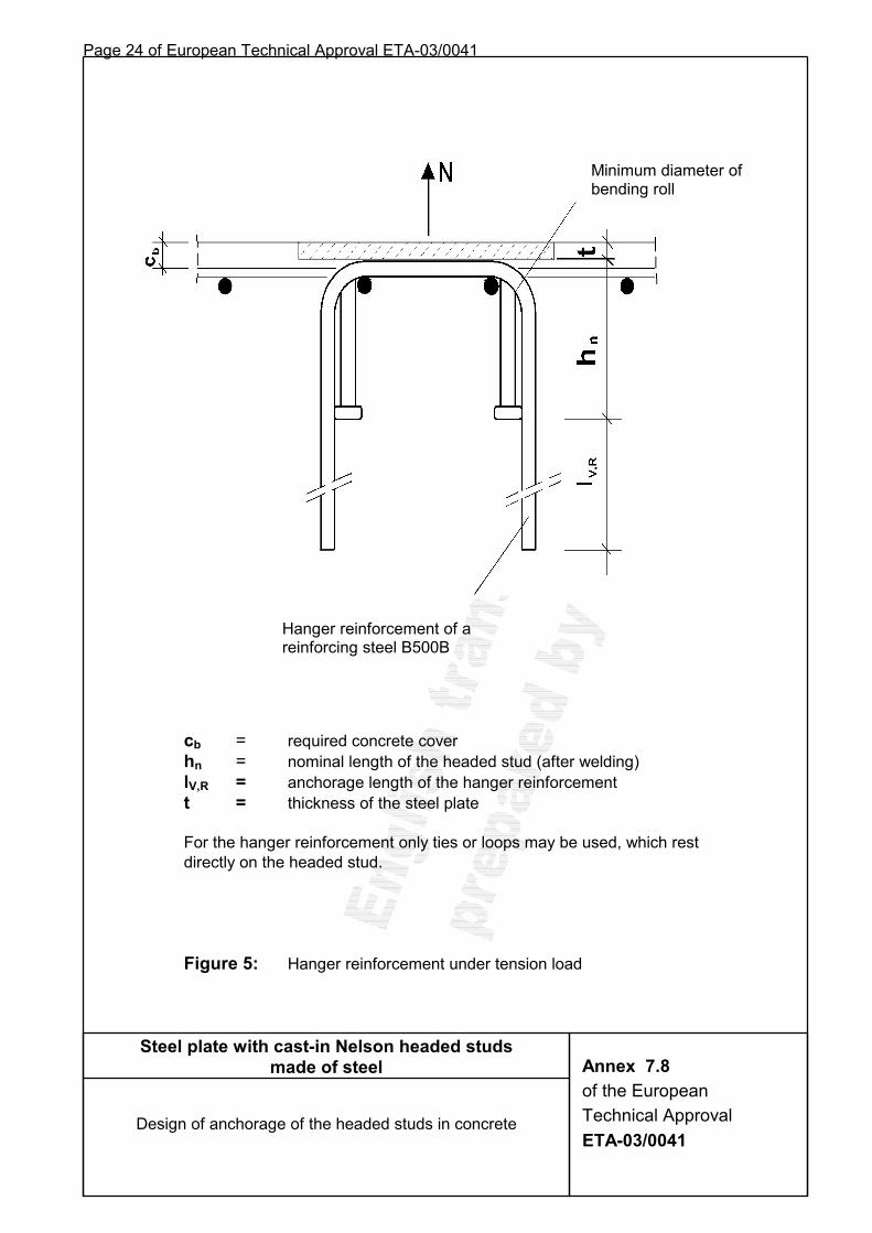
3.6 Characteristic resistance of a hanger reinforcement under tension load
An additional hanger reinforcement may be taken into account for resistance to the tension load, if the length of the headed stud in the concrete is at least 150 mm and the edge distance is c ≥ 1.5 hef.
The reinforcement shall consist of reinforcing steel B 500 B with a diameter of ≤ 16 mm. The characteristic resistance NRk,h of a bar of the hanger reinforcement is given in Table 5, Annex 5 depending on the nominal length of the headed stud (hn) in concrete and the length of the anchorage (lV,R) of the hanger reinforcement.
Where a hanger reinforcement is provided at the headed stud according to Figure 5 Annex 7.8 verification against concrete cone failure needs to be performed only for the limit state of serviceability with γG = γQ = 1.0 and γMc = 1.3. The edge distance is c ≥ 1.5 hef.
The hanger reinforcement shall be anchored at the side opposite to the load direction in the concrete.
For eccentric tension loading all headed studs shall be provided with the reinforcement determined for the maximum loaded headed stud.
Steel plate with cast-in Nelson headed studs made of steel
Design of anchorage of the headed studs in concrete
Annex 7.7 of the European Technical Approval ETA-03/0041
Page 24 of European Technical Approval ETA-03/0041
cb = required concrete cover hn = nominal length of the headed stud (after welding) lV,R = anchorage length of the hanger reinforcement t = thickness of the steel plate For the hanger reinforcement only ties or loops may be used, which rest directly on the headed stud. Figure 5: Hanger reinforcement under tension load
Hanger reinforcement of a reinforcing steel B500B
Minimum diameter of bending roll
Steel plate with cast-in Nelson headed studs made of steel
Design of anchorage of the headed studs in concrete
Annex 7.8 of the European Technical Approval ETA-03/0041
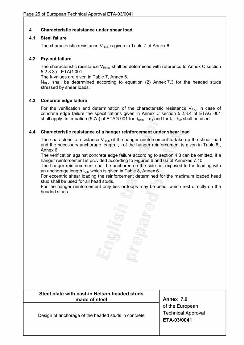
Page 25 of European Technical Approval ETA-03/0041 4 Characteristic resistance under shear load
4.1 Steel failure The characteristic resistance VRk,s is given in Table 7 of Annex 6. 4.2 Pry-out failure The characteristic resistance VRk,cp shall be determined with reference to Annex C section
5.2.3.3 of ETAG 001. The k-values are given in Table 7, Annex 6. NRk,c shall be determined according to equation (2) Annex 7.3 for the headed studs
stressed by shear loads.
4.3 Concrete edge failure For the verification and determination of the characteristic resistance VRk,c in case of
concrete edge failure the specifications given in Annex C section 5.2.3.4 of ETAG 001 shall apply. In equation (5.7a) of ETAG 001 for dnom = d1 and for lf = hef shall be used.
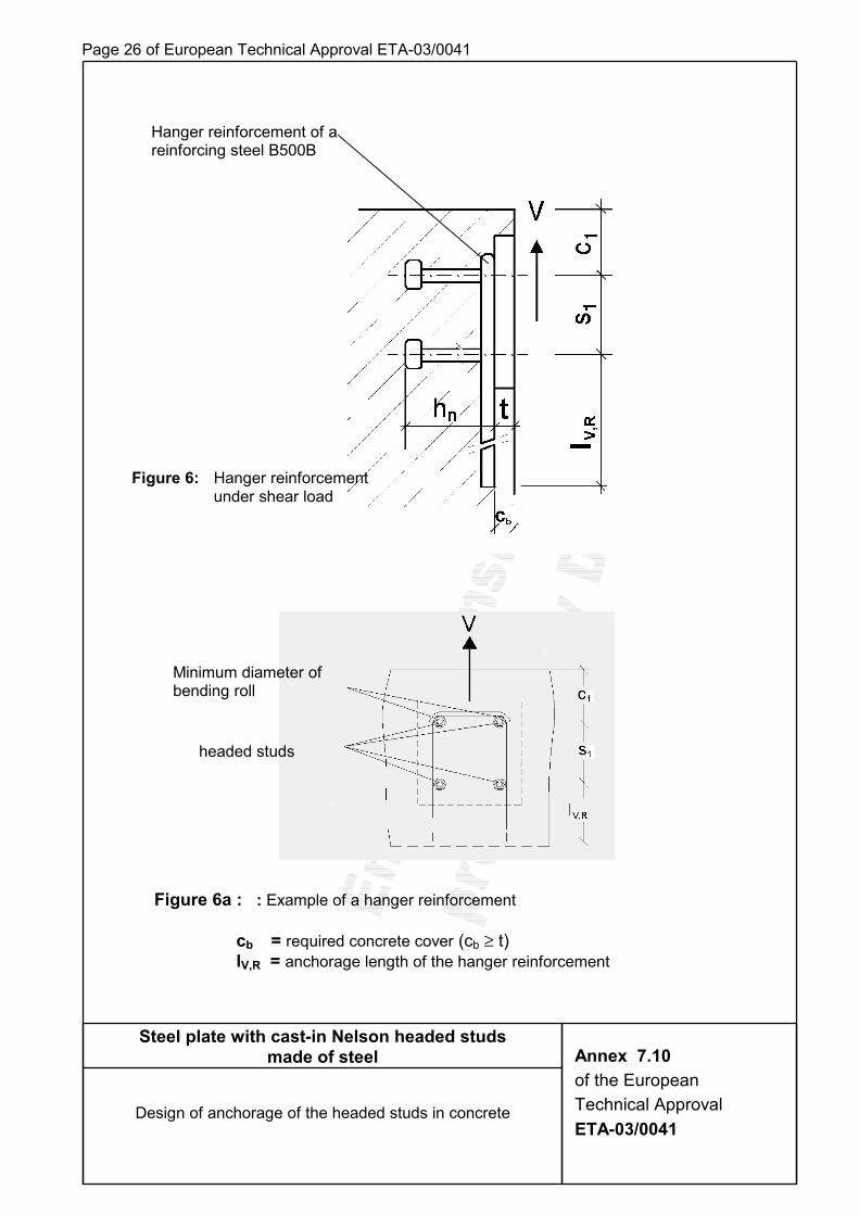
4.4 Characteristic resistance of a hanger reinforcement under shear load The characteristic resistance VRk,h of the hanger reinforcement to take up the shear load and the necessary anchorage length lVR of the hanger reinforcement is given in Table 8 , Annex 6. The verification against concrete edge failure according to section 4.3 can be omitted, if a hanger reinforcement is provided according to Figures 6 and 6a of Annexes 7.10. The hanger reinforcement shall be anchored on the side not exposed to the loading with an anchorage length lV,R which is given in Table 8, Annex 6. For eccentric shear loading the reinforcement determined for the maximum loaded head stud shall be used for all head studs. For the hanger reinforcement only ties or loops may be used, which rest directly on the headed studs.
Steel plate with cast-in Nelson headed studs made of steel
Design of anchorage of the headed studs in concrete
Annex 7.9 of the European Technical Approval ETA-03/0041
Page 26 of European Technical Approval ETA-03/0041
Figure 6a : : Example of a hanger reinforcement
cb = required concrete cover (cb ≥ t) lV,R = anchorage length of the hanger reinforcement
Steel plate with cast-in Nelson headed studs made of steel
Design of anchorage of the headed studs in concrete
Annex 7.10 of the European Technical Approval ETA-03/0041
Hanger reinforcement of a reinforcing steel B500B
Minimum diameter of bending roll
headed studs
Figure 6: Hanger reinforcement under shear load
Page 27 of European Technical Approval ETA-03/0041
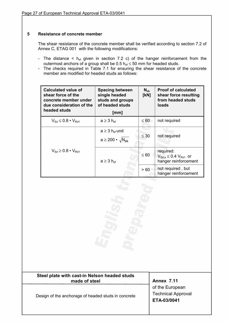
5 Resistance of concrete member
The shear resistance of the concrete member shall be verified according to section 7.2 of Annex C, ETAG 001 with the following modifications:
- The distance < hef given in section 7.2 c) of the hanger reinforcement from the outermost anchors of a group shall be 0.5 hef ≤ 50 mm for headed studs.
- The checks required in Table 7.1 for ensuring the shear resistance of the concrete member are modified for headed studs as follows:
Calculated value of shear force of the concrete member under due consideration of the headed studs
Spacing between single headed studs and groups of headed studs
[mm]
Nsk [kN]
Proof of calculated shear force resulting from headed studs loads
VSd ≤ 0.8 • VRd1 a ≥ 3 hef ≤ 60 not required
a ≥ 3 hef und
a ≥ 200 • skN ≤ 30 not required
≤ 60 required: VSd,a ≤ 0.4 VRd1 or hanger reinforcement
VSd ≥ 0.8 • VRd1
a ≥ 3 hef
> 60 not required , but hanger reinforcement
Steel plate with cast-in Nelson headed studs made of steel
Design of the anchorage of headed studs in concrete
Annex 7.11 of the European Technical Approval ETA-03/0041
Diese europäische technische Zulassung umfasst
This European Technical Approval contains
27 Seiten einschließlich 7 Anhänge 27 pages including 7 annexes
European Organisation for Technical Approvals Europäische Organisation für Technische Zulassungen
83230.03 / 8.06.01-0028/03
Deutsches Institut für Bautechnik Anstalt des öffentlichen Rechts 10829 Berlin, Kolonnenstraße 30 L Tel.: +49(0)30-78730-0 Fax: +49(0)30-78730-320 e-Mail: [email protected]
Ermächtigtu n d n o t i f i z i e r t
gemäß Art ikel 10 derRichtlinie des Rates vom
21. Dezember 1988 zur An-gleichung der Rechts- undVerwaltungsvorschriften
d er M i tg l ie ds taa tenüber Bauprodukte
(89/106/EWG)
Mitglied der EOTA
European Technical Approval ETA-03/0042
Handelsbezeichnung Trade name
Nelson-Kopfbolzen aus nichtrostendem Stahl
Zulassungsinhaber
Holder of approval Nelson Bolzenschweiß-Technik GmbH & Co. KG Flurstraße 7-19 58285 Gevelsberg
Zulassungsgegenstand und Verwendungszweck
Stahlplatte mit einbetonierten Nelson-Kopfbolzen aus nichtrostendem Stahl
Generic type and use of construction product
Steel plate with cast-in Nelson-headed studs of stainless steel
Geltungsdauer vom Validity from
13. November 2003
bis to
13. November 2008
Herstellwerk 1 Herstellwerk 2 Herstellwerk
Manufacturing plant

Page 2 of European Technical Approval ETA-03/0042
83230.03
I LEGAL BASES AND GENERAL CONDITIONS
1 This European Technical Approval is issued by Deutsches Institut für Bautechnik in accordance with:
− Council Directive 89/106/EEC of 21 December 1988 on the approximation of laws, regulations and administrative provisions of Member States relating to construction products1, amended by the Council Directive 93/68/EEC of 22 July 19932;
− Gesetz über das Inverkehrbringen von und den freien Warenverkehr mit Bauprodukten zur Umsetzung der Richtlinie 89/106/EWG des Rates vom 21. Dezember 1988 zur Angleichung der Rechts- und Verwaltungsvorschriften der Mitgliedstaaten über Bauprodukte und anderer Rechtsakte der Europäischen Gemeinschaften (Bauproduktengesetz - BauPG) vom 28. April 19983;
− Common Procedural Rules for Requesting, Preparing and the Granting of European Technical Approvals set out in the Annex of Commission Decision 94/23/EC4;
2 Deutsches Institut für Bautechnik is authorized to check whether the provisions of this European Technical Approval are met. Checking may take place in the manufacturing plant. Nevertheless, the responsibility for the conformity of the products to the European Technical Approval and for their fitness for the intended use remains with the holder of the European Technical Approval.
3 This European Technical Approval is not to be transferred to manufacturers or agents of manufacturers other than those indicated on page 1, or manufacturing plants other than those indicated on page 1 of this European Technical Approval.
4 This European Technical Approval may be withdrawn by Deutsches Institut für Bautechnik, in particular after information by the Commission on the basis of Article 5 (1) of Council Directive 89/106/EEC.
5 Reproduction of this European Technical Approval including transmission by electronic means shall be in full. However, partial reproduction can be made with the written consent of the Deutsches Institut für Bautechnik. In this case partial reproduction has to be designated as such. Texts and drawings of advertising brochures shall not contradict or misuse the European Technical Approval.
6 The European Technical Approval is issued by the approval body in its official language. This version corresponds to the version circulated within EOTA. Translations into other languages have to be designated as such.
1 Official Journal of the European Communities N° L 40, 11.02.1989, p. 12 2 Official Journal of the European Communities N° L 220, 30.08.1993, p. 1 3 Bundesgesetzblatt I, p. 812, zuletzt geändert durch Gesetz ('last amended by law on') vom 15.12.2001,
Bundesgesetzblatt I, p. 3762 4 Official Journal of the European Communities N° L 17, 20.01.1994, p. 34
Page 3 of European Technical Approval ETA-03/0042
83230.03
II SPECIFIC CONDITIONS OF THE EUROPEAN TECHNICAL APPROVAL
1 Definition of product and intended use
1.1 Definition of product The steel plate with cast-in Nelson-headed studs consists of one or more headed studs which are welded-on to a steel plate. The product consist of stainless steel. The headed studs have a diameter of the shaft of 10, 13, 16, 19 and 22 mm. At the one end a head is formed by upsetting. The other end is prepared for drawn arc stud welding with ceramic ferrule or shielding gas (method 783 according to EN ISO 4063:2002-02). The product is surface-flush anchored in the concrete. For the installed product see figure given in Annex 1.
1.2 Intended use The steel plate with welded-on headed studs is intended for uses where requirements concerning mechanical resistance and stability as well as safety in use in the sense of the Essential Requirements ER1 and ER4 of the Directive 89/106/EEC shall be satisfied and where failure of the anchorage may cause risk to human life and health and/or lead to considerable economic consequences. Regarding the requirements concerning safety in case of fire (ER 2) it is assumed that the construction product meets the requirements of class A1 in relation to reaction to fire in accordance with the stipulations of the Commission decision 96/603/EC, amended by 200/605/EC. If the fire resistance is relevant then the fire resistance of the concrete member in which the construction product is anchored is to be tested according to test method provided in order to be classified according to prEN 13 501-2. The steel plate with welded-on headed studs is to be used for the anchorage under static or quasi static actions as well as under not predominantly static actions (fatigue actions) in reinforced normal concrete of the minimum strength class C 20/25 according to EN 206-1:2000-07. The construction product may be anchored in cracked and non-cracked concrete. The anchorage is admissible with single studs or groups of studs, which consist of two up to nine headed studs. The construction product can be stressed by a tensile load, shear load or a combination of tensile and shear loads. The steel plate with the welded-on headed studs is anchored in the concrete surface-flush. Other steel components may be welded-on to the steel plate. The steel plate from stainless steel (1.4571; 1.4401) with welded-on headed studs from stainless steel (1.4301; 1.4303) may be used in concrete components subject to dry internal conditions and in concrete components subject to external atmospheric exposure (including industrial and marine environment) or exposure in permanently damp internal conditions, if no particular aggressive conditions exist. Such particular aggressive conditions are, e.g. permanent, alternating immersion in seawater or the splash zone of seawater, chloride atmosphere of indoor swimming pools or atmosphere with extreme chemical pollution (e.g. in desulphurization plants or road tunnels where de-icing material is used).. The provisions made in this European Technical Approval are based on an assumed intended working life of the product of 50 years. The indications given on the working life cannot be interpreted as a guarantee given by the producer, but are to be regarded only as a means for choosing the right products in relation to the expected economically reasonable working life of the works.
Page 4 of European Technical Approval ETA-03/0042
83230.03
2 Characteristics of the product and method of verification
2.1 Characteristics of the product
2.1.1 General The characteristic material values, dimensions and tolerances of the product not indicated in
the Annexes shall correspond to respective values laid down in the technical documentation5 of this European Technical Approval.
The characteristic values for the design calculation of the anchorage are given in Annexes 4 to 6.
2.1.2 Headed stud The headed studs made of stainless steel according to EN ISO 13 918-1998-10 "Studs and ceramic ferrules for arc stud welding" shall correspond to the materials, mechanical properties and dimensions given in Table 1 and 2, Annex 3. It is also permissible to use two headed studs welded one on top of the other by arc stud welding (see Annex 2). A padded ring is to be placed under the head of the first stud. The padded ring is to be secured in its position to make a permanent compression of ≥ 5 mm possible. The padded ring can be made, for example, of technical felt or cellular rubber. The external diameter of the padded ring shall exceed the head diameter and the inside diameter shall be less than the shaft diameter. The padded ring shall prevent a contact of the lower head at the concrete and a transmission of loads by the lower stud head.
2.1.3 Steel plate The steel plates, on which headed studs of stainless steel (1.4301; 1.4303) according to Table 2, Annex 3 will be welded, shall consist of the materials 1.4571 or 1.4401 according to Table 2 Annex 3.
Because of the stress of the steel plate in the direction of the thickness a possibly not homogeneous structure of the steel plate in this direction shall be taken into account. At the same time the risk of lamellar tearing as well as lamellar imperfections in the steel plate shall be paid attention to.
For not predominantly static loads ultrasonic tested steel plates shall be used. 2.1.4 Welded joint
The headed studs shall be welded to the steel plate by means of drawn arc stud welding with ceramic ferrules or shielding gas in accordance with EN ISO 14555:1998. Welding of the headed studs via arc stud welding may be performed in the manufacturing plant or on the construction site. For the safeguarding of the quality assurance of the welded connection the provisions of EN ISO 14 555:1998 "Welding – Arc stud welding of metallic materials" and EN 729 "Quality requirements for welding – Fusion welding of metallic materials" shall apply for the executing company.
2.1.5 Marking The headed stud is identified according to the diameter of shaft and the nominal length of the
headed stud, e.g. 16/75. Each headed stud is marked with the identifying mark of the producer and the material according to Annex 3.
5 The technical documentation for this European Technical Approval is deposited at Deutsches Institut für Bautechnik
and, as far as relevant for the tasks of the approved bodies involved in the attestation of conformity procedure, is handed over to the approved bodies.

Page 5 of European Technical Approval ETA-03/0042
83230.03
2.2 Methods of verification
2.2.1 General The assessment of the fitness of the product for the intended use with regard to the
requirements of mechanical resistance and stability as well as safety in use in the sense of the Essential Requirements 1 and 4 was performed based on the ETAG 001 "Guideline for European Technical Approval of Metal Anchors for Use in Concrete" and the tests carried out.
2.2.2 Tests carried out The following tests were carried out for determination the characteristic resistance of the headed stud under different conditions. 1. Tests for determination of the steel resistance under tension load 2. Concrete cone failure, centric tension tests with single fastening without influence of
spacing and edge distance. 3. Blow-out failure, centric tension tests with single fastening; member edge c1 = 60 mm.
2.2.3 Calculated verifications
2.2.3.1 Basic values for the characteristic resistance under tension load (1) Steel failure
The characteristic resistance NRk,s for the cross section of the shaft is determined according to Annex C, clause 5.2.2.2 of ETAG 001 and proved by the test series 1, clause 2.2.2. The characteristic resistance in case of steel failure is given in Table 4 Annex 5. (2) Pull-out failure
The characteristic resistance NRk,p in case of failure by pull-out is given in Table 4 Annex 5. (3) Concrete cone failure
The test values (mean values) resulting from test series 2 of clause 2.2.2 prove the calculation values with reference to ETAG 001. The characteristic resistance NRk,c in case of concrete cone failure is determined according to Annex 7 clause 3.3. (4) Blow out failure The test values (mean values) resulting from test series 3 of clause 2.2.2 prove the calculation values with reference to ETAG 001. The characteristic resistance NRk,cb in case of blow out failure is determined according to Annex 7 clause 3.4. (5) Splitting failure due to loading
The required cross section of the minimum reinforcement shall be determined according to Annex 7 clause 3.5. (6) Characteristic resistance of hanger reinforcement under tension load
The characteristic resistance NRk,h of a bar of the hanger reinforcement depending on the nominal length of the headed stud (hn) and the anchorage length (lV,R) of the hanger reinforcement is given in Table 5 Annex 5.
2.2.3.2 Basic values for the characteristic resistance under shear load (1) Steel failure without lever arm
The characteristic resistance VRk,s for the cross section of the shaft was determined with reference to Annex C of ETAG 001. The α-value is 0.6 . The characteristic resistance in case of steel failure is given in Table 7 Annex 6. (2) Pry-out failure (concrete pry-out failure at the side opposite to the load direction) The characteristic resistance VRk,cp shall be determined with reference to Annex C clause 5.2.3.3 of ETAG 001 and according to Annex 7 clause 4.2.

Page 6 of European Technical Approval ETA-03/0042
83230.03
(3) Concrete edge failure The characteristic resistance VRk,c in case of concrete edge failure under shear load is determined with reference to Annex C clause 5.2.3.4 of ETAG 001 and according to Annex 7 clause 4.3. (4) Characteristic resistance of hanger reinforcement under shear load The characteristic resistance VRk,h of a bar of the hanger reinforcement with the corresponding anchorage length IV,R is given in Table 8 Annex 6.
3 Attestation of conformity of the product and CE marking
3.1 System of attestation of conformity The system of attestation of conformity 2(i) (referred to as System 1) according to Council Directive 89/106/EEC Annex III laid down by the European Commission provides: (a) tasks for the manufacturer (1) factory production control; (2) further testing of samples taken at the factory by the manufacturer in accordance with a prescribed test plan; (b) tasks for the approved body (3) initial type-testing of the product; (4) initial inspection of factory and of factory production control; (5) continuous surveillance, assessment and approval of factory production control.
3.2 Responsibility
3.2.1 Tasks for the manufacturer; factory production control The manufacturer has a factory production control system in the plant and exercises
permanent internal control of production. All the elements, requirements and provisions adopted by the manufacturer are documented in a systematic manner in the form of written policies and procedures. The factory production control system ensures that the product is in conformity with this European Technical Approval.
The manufacturer shall only use raw materials supplied with the relevant inspection documents as laid down in the prescribed test plan6. The incoming raw materials shall be subject to controls and tests by the manufacturer before acceptance. The check shall include control of inspection documents (comparison with nominal values) presented by the manufacturer of the raw materials by inspecting the dimensions and determination of the material properties. The material properties (tensile strength) of the raw materials of the headed stud are to be determined. The dimensions on the manufactured components of the product are to be checked. The required verifications and requirements for drawn arc stud welding according to EN ISO 14555:1998 shall be fulfilled.
The frequency of controls and tests conducted during production is laid down in the prescribed test plan6 taking account of the manufacturing process of the product.
6 The prescribed test plan has been deposited at the Deutsches Institut für Bautechnik and is handed over only to the
approved bodies involved in the conformity attestation procedure.

Page 7 of European Technical Approval ETA-03/0042
83230.03
The results of the factory production control are recorded and evaluated. The records include at least the following information: - designation of the product, the basic materials and the components; - type of control or testing; - date of manufacture of the product and date of testing of the product or of the basic
materials and components; - results of control and testing and, if appropriate, comparison with the requirements; - signature of person responsible for the factory production control.
The records shall be presented to the inspection body involved in the continuous surveillance. On request they shall be presented to Deutsches Institut für Bautechnik.
Details of extent, nature and frequency of testing and controls to be performed within the factory production control shall correspond to the prescribed test plan6, which is part of the technical documentation of this European Technical Approval.
3.2.2 Tasks for the approved bodies
3.2.2.1 Initial type-testing of the product For initial type-testing the results of the tests performed as part of the assessment for the
European Technical Approval shall be used unless there are changes in the production line or plant. In such cases the necessary initial type-testing has to be agreed between the Deutsches Institut für Bautechnik and the approved bodies involved.
3.2.2.2 Initial inspection of factory and of factory production control The approved body shall ascertain that, in accordance with the prescribed test plan6, the
factory, in particular the staff and equipment, and the factory production control are suitable to ensure a continuous and orderly manufacturing of the product with the specifications mentioned in 2.1 as well as in the Annexes to the European Technical Approval.
3.2.2.3 Continuous surveillance The approved body shall visit the factory at least once a year for surveillance. It has to be
verified that the system of factory production control and the specified manufacturing process are maintained taking account of the prescribed test plan6.
Continuous surveillance and assessment of factory production control have to be performed according to the prescribed test plan6.
The results of product certification and continuous surveillance shall be made available on demand by the certification body or inspection body, respectively, to the Deutsches Institut für Bautechnik. In cases where the provisions of the European Technical Approval and the prescribed test plan6 are no longer fulfilled the conformity certificate shall be withdrawn.
3.3 CE marking The CE marking shall be affixed to each packaging or on the accompanying documents of the product. In addition to the initials "CE" the following information shall be given: - identification number of the certification body; - name or identifying mark of producer and manufacturing plant; - the last two digits of the year in which the CE marking was affixed; - number of the EC certificate of conformity; - number of the European Technical Approval; - name of the product.
Page 8 of European Technical Approval ETA-03/0042
83230.03
4 Assumptions under which the fitness of the product for the intended use was favourably assessed
4.1 Manufacturing The product is manufactured in accordance with the provisions of the European Technical
Approval using the manufacturing process as identified in the inspection of the plant by the Deutsches Institut für Bautechnik and the approved body and laid down in the technical documentation.
4.2 Installation
4.2.1 Design of anchorages The fitness of the product for the intended use is given under the following condition:
The design of the anchorage is based on the design method in Annex 7 under the responsibility of an engineer experienced in anchorages and concrete building. Verifiable calculation notes and drawings are prepared taking account of the loads to be anchored. The transfer of the loads to be anchored in the concrete member is verified. Single studs or groups of studs consisting of two to nine headed studs according to Annex 4 are used. Headed studs of the same diameter and length are used only in a group of headed studs. The position of the product is indicated on the design drawings (e.g. position of the headed studs towards the reinforcement or the supports).
Because of the stress of the steel plate in the direction of the thickness a possibly not homogeneous structure of the steel plate in this direction shall be taken into account. At the same time the risk of lamellar tearing as well as lamellar imperfections in the steel plate shall be paid attention to.
For not predominantly static loads ultrasonic tested steel plates shall be used. On the anchorage of not predominantly static action the following characteristic range of steel stresses may not be exceeded: - tensile load ∆σ = 100 N/mm² - shear loading ∆τ = 35 N/mm² - hanger reinforcement ∆σ = 60 N/mm² The partial safety factor for fatigue strength may be taken with γMf = 1.35 .
4.2.2 Installation The fitness of the anchorage for the intended use can be assumed only, if the following
installation conditions are kept: - Installation carried out by appropriately qualified personnel and under the supervision
of the person responsible for technical matters on site. - Use of the product only as supplied by the manufacturer without exchanging the
components. - Installation in accordance with the manufacturer's specifications and the design
drawings with exact position, dimensions of the steel plate and size and length of the headed studs.
- The anchorage shall be fixed to the formwork or auxiliary constructions in a way that no movement of the product will occur during placing of reinforcement or during placing and compacting of the concrete.
- The concrete under the head of the headed stud shall be properly compacted (no cavities). For large fixtures (steel plate > 400 mm x 400 mm) vent openings shall be provided. These shall be specified in the installation instructions.
- Observation of the prescribed values of installations.
Page 9 of European Technical Approval ETA-03/0042
83230.03
Welding-on of the intended and designed steel components to the cast-in construction product may only be performed by companies meeting the corresponding quality requirements for welding according to EN 729 "Quality requirements for welding – Fusion welding of metallic materials".
4.2.3 Responsibility of the manufacturer It is in the responsibility of the manufacturer to ensure that the information on the specific conditions according to 1 and 2 including Annexes referred to and 4.2.1 and 4.2.2 is given to those who are concerned. This information may be made by reproduction of the respective parts of the European Technical Approval. In addition all installation data shall be shown clearly on the package and/or on an enclosed instruction sheet, preferably using illustration(s). The minimum data required are: - Dimensions of the steel plate, - diameter of the headed studs, - length of the headed studs, - number of the headed studs, - material of the steel plate, - material of the headed studs and - details on the installation of procedure, preferably by using illustrations. All data shall be presented in a clear and explicit form.
Prof. Dr.-Ing. Bossenmayer Beglaubigt: Reimold
Page 10 of European Technical Approval ETA-03/0042
Steel plate with cast-in Nelson headed studs made of stainless steel
Product and intended use
Annex 1 of the European Technical Approval ETA-03/0042
steel plate
concrete member
headed stud
hef = effective anchorage depth h = thickness of concrete member
Page 11 of European Technical Approval ETA-03/0042
d1 = diameter of shaft d2 = diameter of head hef = effective anchorage depth hn = nominal length of the headed stud (after welding) k = thickness of the head t = thickness of the steel plate αααα = 90°
Steel plate with cast-in Nelson headed studs made of stainless steel
Details of the construction product
Annex 2 of the European Technical Approval ETA-03/0042
1 headed stud
2 steel plate
1 headed studs
padded ring
2 steel plate
hef = hn – k (if the theoretic cone meets the steel plate at angle of ~ 30°)
hef = hn – k +t
hef = hn1 + hn2 - k2 + t
α
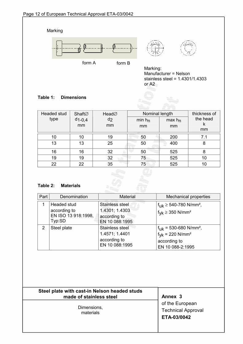
Page 12 of European Technical Approval ETA-03/0042
Table 1: Dimensions
Nominal length Headed stud type
Shaft∅ d1-0,4
mm
Head∅ d2
mm min hn
mm max hn
mm
thickness of the head
k mm
10 10 19 50 200 7.1 13 13 25 50 400 8
16 16 32 50 525 8 19 19 32 75 525 10 22 22 35 75 525 10
Table 2: Materials
Part Denomination Material Mechanical properties
1 Headed stud according to EN ISO 13 918:1998, Typ:SD
Stainless steel 1.4301; 1.4303 according to EN 10 088:1995
fuk ≥ 540-780 N/mm², fyk ≥ 350 N/mm²
2 Steel plate Stainless steel 1.4571; 1.4401 according to EN 10 088:1995
fuk = 530-680 N/mm², fyk = 220 N/mm² according to EN 10 088-2:1995
Steel plate with cast-in Nelson headed studs made of stainless steel
Dimensions,
materials
Annex 3 of the European Technical Approval ETA-03/0042
Marking
form A form B Marking: Manufacturer = Nelson stainless steel = 1.4301/1.4303 or A2
Page 13 of European Technical Approval ETA-03/0042
Table 3: Installation
Nominal size (mm) 10 13 16 19 22
anchorage depth min hef [mm]
50 50 50 75 75
minimum spacing smin [mm] 50 70 80 100 100 minimum edge distance cmin [mm] 50 50 50 70 70 characteristic spacing scr [mm] 3 hef
characteristic edge distance ccr [mm] 1.5 hef
minimum thickness of concrete member
hmin [mm] hef + k + cb1)
1) cb = required concrete cover according to national regulations
Steel plate with cast-in Nelson headed studs made of stainless steel
Installation,
arrangement of the headed studs
Annex 4 of the European Technical Approval ETA-03/0042
Arrangement of the headed studs
headed stud steel plate
Page 14 of European Technical Approval ETA-03/0042 Table 4: Characteristic values of resistance to tension loads of design
according to Annex 7
Headed stud – nominal size 10 13 16 19 22 Steel failure Characteristic resistance NRk,s [kN] 39 67 103 146 197 Partial safety factor γMs x) 1.85 Pull-out failure Characteristic resistance NRk,p [kN] 30 50 90 75 85 Increasing factors ψ for the characteristic resistance
C30/37 C40/50 C50/60
1.22 1.41 1.55
Partial safety factor γMp x) 1.8 Concrete cone failure Effective anchorage depth hef [mm] hn – k + t Characteristic spacing scr,N [mm] 3hef Characteristic edge distance ccr,N [mm] 1.5hef Partial safety factor γMc x) 1.8 Blow-out failure Partial safety factor γMcb x) 1.8
Table 5: Characteristic resistance of a hanger reinforcement bar and anchorage
length of the hanger reinforcement
Hanger reinforcement concrete reinforcing steel B 500B ∅ 12 ∅ 14 ∅ 16
hn 1) ≥ 150 mm 27 36 45
hn 1) ≥ 200 mm 31 40 50
hn 1) ≥ 300 mm 35 44 55
Characteristic resistance of a hanger reinforcement bar NRk,h [kN]
hn 1) ≥ 350 mm 37 47 59
Anchorage length of the hanger reinforcement IVR [mm] 660 770 880 Partial safety factor γMh x) 1.8 1) hn = Nominal length of the headed stud
x) In absence of national rules, the partial safety factors given in Tables 4 and 5 are
recommended.
Table 6: Displacement under tensile load
Headed stud – nominal size 10 13 16 19 22 Displacements1) to 0.7 mm under following loads in [kN]
14
20
25
30
35
1) The indicated displacements are valid for short term loading, the displacements can be increased under long term loading to 1.8 mm.
Steel plate with cast-in Nelson headed studs made of stainless steel
Characteristic values of resistance under tension loads, displacements
Annex 5 of the European Technical Approval ETA-03/0042
Page 15 of European Technical Approval ETA-03/0042
Table 7: Characteristic values of resistance to shear loads of design according
to Annex 7
Headed stud – nominal size 10 13 16 19 22 Steel failure Characteristic resistance VRk,s [kN] 23 40 62 88 118 Partial safety factor γMs x) 1.54 Concrete pry-out failure Factor in equation (5.6) Annex C section 5.2.3.3 of ETAG 001, NRk,c according to Annex 7, section 3.3
k
2.0
Partial safety factor γMcp x) 1.8 Concrete edge failure Effective length of the headed stud lf = hef [mm] hn – k + t Effective outside diameter dnom = d1
[mm] 10 13 16 19 22
Partial safety factor γMc x) 1.8
Table 8: Characteristic tension resistance of a hanger reinforcement bar and anchorage length of the hanger reinforcement
Hanger reinforcement concrete reinforcing steel B 500B ∅ 8 ∅ 10 ∅ 12 ∅ 14 ∅ 16
Characteristic resistance of a hanger reinforcement bar VRk,h [kN] 12 19 28 38 50
Anchorage length of the hanger reinforcement lVR [mm] 440 550 660 770 880
Partial safety factor γMh x) 1.15
x) In absence of national rules, the partial safety factors given in Tables 7 and 8 are recommended.
Table 9: Displacements under shear load
Headed stud – nominal size 10 13 16 19 22 Displacements1) to 1.5 mm under following loads in [kN]
15
20
30
45
60
1) The indicated displacements are valid for short term loading, the displacements can be increased under long term loading to 2.0 mm.
Steel plate with cast-in Nelson headed studs made of stainless steel
Characteristic values of resistance to shear loads, displacements
Annex 6 of the European Technical Approval ETA-03/0042
Page 16 of European Technical Approval ETA-03/0042
Design of anchorage of the headed studs in concrete Table of contents
1 General
2 Required verifications
3 Characteristic resistance under tension load 3.1 Steel failure
3.2 Pull-out failure
3.3 Concrete cone failure
3.4 Blow-out failure
3.5 Splitting failure
3.6 Characteristic resistance of a hanger reinforcement under tension load
4 Characteristic resistance under shear load 4.1 Steel failure
4.2 Concrete pry-out failure
4.3 Concrete edge failure
4.4 Characteristic resistance of a hanger reinforcement under shear load
5 Resistance of concrete member
Steel plate with cast-in Nelson headed studs made of stainless steel
Design of anchorage of the headed studs in concrete
Annex 7 of the European Technical Approval ETA-03/0042
Page 17 of European Technical Approval ETA-03/0042 Design 1 General The design method is used for the design of the anchorage of headed studs in
concrete. It is based on the assumption that sufficient experiences are available from tests with headed bolts and metal anchors, since the design method for metal anchors (Annex C of ETAG 001) has also been derived from these tests.
The proposed design for headed studs shall be considered as transitional solution until
the design method being prepared in CEN/TC250/SC2/WG2 will be available. The design of the headed stud is based on Annex C of ETAG 001. Anchorage is admissible only by using single headed studs or several headed studs
(groups), see Annex 4. Other arrangements e.g. in a triangular or circular pattern are also allowed; however, the provisions of this design method should be applied with engineering judgement.
The anchorage may be designed as a group only, if the acting loads are transmitted via the sufficiently stiff steel plate into the individual headed studs of the group.
It is only allowed to use the same diameter and length in a group. The action-effects of the headed studs on the concrete surface shall be calculated
from the forces and moments acting at the steel plate according to the theory of elasticity with the following assumptions:
− The steel plate remains plane under the action-effects. − The stiffness of all headed studs is identical. It corresponds to the stiffness of the
steel cross-section. − The module of elasticity of the concrete shall be taken with Ec = 30.000 N/mm2. For anchorages at the member edge subjected to shear loading only the headed studs
near the edge may be used for bearing the load. The concrete member shall be of normal weight concrete of at least strength class
C20/25]. Terminology and symbols for actions, resistances and indices shall be applied
according to clause 2 of Annex C of ETAG 001.
Steel plate with cast-in Nelson headed studs made of stainless steel
Design of anchorage of the headed studs in concrete
Annex 7.1 of the European Technical Approval ETA-03/0042
Page 18 of European Technical Approval ETA-03/0042 2 Required verifications The design of the headed studs shall be based on the safety concept with partial
safety factors according to Annex C, ETAG 001. The required verifications of the resistances are shown in Table 2.1 and 2.2.
Table 2.1: Required verifications for resistance to tension loading
Failure mode Single anchorage Groups
Steel failure (head stud) NSd ≤ NRk,s / γMs NSdh ≤ NRk,s / γMs
Pull-out failure NSd ≤ NRk,p / γMc NSdh ≤ NRk,p / γMc
Concrete cone failure without hanger reinforcement
NSd ≤ NRk,c / γMc NSdg ≤ NRk,c / γMc
Blow-out failure NSd ≤ NRk,cb / γMc NSdg ≤ NRk,cb / γMc
Hanger reinforcement
NSd ≤ NRk,h / γMh NSdh ≤ NRk,h / γMh Concrete cone failure
with hanger reinforcement Concrete cone NSk ≤ NRk,c / 1.3 NSk
g ≤ NRk,c / 1.3
Splitting failure Minimum reinforcement acc. to 3.5
Table 2.2: Required verifications for resistance to shear loading
Failure mode Single anchorage Groups Steel failure (head stud) VSd ≤ VRk,s / γMs VSd
h ≤ VRk,s / γMs Concrete pry-out failure VSd ≤ VRk,cp / γMc VSd
g ≤ VRk,cp / γMc Concrete edge failure 1) VSd ≤ VRk,c / γMc VSd
g ≤ VRk,c / γMc Resistance of hanger reinforcement with anchorages near the edge VSd ≤ VRk,h / γMh VSd
h ≤ VRk,h / γMh 1) This verification is not required, if there is a hanger reinforcement (see section 4.4).
In the case of a combined tension and shear loading the following Equation shall be observed:
(NSd/NRd)α + (VSd/VRd)α < 1 (1) The ratios NSd/NRd and VSd/VRd shall each be given the maximum value from the
individual failure modes. For the anchorages without hanger reinforcement or for anchorages with hanger
reinforcement for tension load and shear load the α-value in Equation (1) shall be taken with 1.5. Where either a hanger reinforcement for tension load (section 3.6) or a hanger reinforcement for shear loading at the edge (section 4.4) is taken into account for the design, the α-value shall be taken with 2/3.
Steel plate with cast-in Nelson headed studs made of stainless steel
Design of anchorage of the headed studs in concrete
Annex 7.2 of the European Technical Approval ETA-03/0042

Page 19 of European Technical Approval ETA-03/0042
3 Characteristic resistance under tension load 3.1 Steel failure The characteristic resistance NR k , s of a headed stud shall be determined according to Annex C section 5.2.2.2 of ETAG 001 and is given in Table 4 of Annex 5. 3 . 2 P u l l - o u t f a i l u r e The characteristic resistance NRk ,p of a headed stud is given in Table 4 of Annex 5. 3.3 Concrete cone failure W ith r ef er ence to Annex C of ET AG 001 the char acter istic r esistance to tension load of a headed stud or a g r oup of headed studs in case of concr ete cone f ailur e shall be
determined as follows:
N Rk ,c = N Rkco, •
NcN,c,AAo • Ψs,N • Ψre,N • Ψec,N [ N ] ( 2 )
T h e d i f f e r e n t f a c t o r s o f e q u a t i o n ( 2 ) a r e g i v e n b e l o w :
a) The initial value of the characteristic resistance of a headed stud in concrete is obtained by: N Rkco, = 8 3 0
cube,ckf• h5.1ef [ N ] ( 2 a ) with - f ck,cube [ N / m m ² ] ; w i t h f ck,cube m a x i m u m 6 0 N / m m ² . - h ef [mm] is given in Table 4 of Annex 5.
b) The geometric effect of spacing and the edge distances on the characteristic
resistance is taken into account by the ratio Ac,N / Ac,No.
with:
A c , N o = area of concrete cone of a single headed stud with large spacing and
edge distance at the concrete surface, idealized the concrete cone as a pyramid with a height equal to hef and a basic length equal to 3hef (see Figure 1).
A c,N = actual area of concrete cone of the anchorage at the concrete surface. It is limited by overlapping concrete cones of adjoining anchors ( s ≤ 3hef) as well as by the concrete member (c ≤ 1.5hef) . Example for the calculation of Ac,N see Figure 2. The influencing factors (Ψs,N , Ψre,N , Ψec,N) shall be determined according to sub-sections c), d), and e) of Annex C section 5.2.2.4 ETAG 001. scr,N shall be taken with 3hef, and ccr,N with 1.5hef.
Steel plate w ith cast-in Nelson headed studs m a d e o f s t a i n l e s s s t e e l Design of anchor age of the headed studs in concr ete
A n n e x 7 3 3 o f t h e E u r o p e a n
T e c h n i c a l A p p r o v a l E T A - 0 3 / 0 0 4 2

Page 20 of European Technical Approval ETA-03/0042
Steel plate with cast-in Nelson headed studs made of stainless steel
Design of anchorage of the headed studs in concrete
Annex 7.4 of the European Technical Approval ETA-03/0042
Figure 1: Idealized concrete cone failure and area 0N,cA of concrete cone
of an individual headed stud
Ac,N = (c1+s1+1.5hef)(c2+s2+1.5hef) if : c1 ; c2 ≤≤≤≤ 1.5hef s1 ; s2 ≤≤≤≤ 3hef
Figure 2: Example of actual areas Ac,N of the idealized concrete cones of headed stud in the case of axial tension load
concrete cone failure

Page 21 of European Technical Approval ETA-03/0042
3.4 Blow-out failure The characteristic resistance NRk,cb of a headed stud in case of local concrete blow-out
failure at the edge shall be determined with reference to Annex C, ETAG 001 as follows:
N,ecNb,s0Nb,c
Nb,c0cb,Rkcb,Rk A
ANN ψ⋅ψ⋅⋅= [N] (3)
The verification against local concrete blow out failure at the member edge shall be made always, where the edge distance is c ≤ 0.5 hef in one direction. In the following the individual factors of equation (3) are given: a) The initial value of the characteristic resistance of a headed stud is
cube,ck110
cb,Rk fdc5.8N ⋅⋅⋅= [N] (3a) fck,cube [N/mm²], c1 und d1 [mm] For fck,cube = 60 N/mm² as maximum.
b) The influence of spacing and edge distances on the characteristic resistance is taken into account by the ratio Ac,Nb / o
Nb,cA :
Ac,Nbo = 36 c1
2; projected area of an individual headed stud (on the lateral surface of the concrete), assuming the concrete cone as a pyramid with the peak in the middle of the head, with a height equal to c1 and a base length equal to 6 c1 (see Figure 3).
Ac,Nb = existing projected area (on the lateral surface of the concrete).
For the calculation the concrete cone shall be idealized as above and the overlapping of the projected areas of adjoining headed studs shall be noted. An example for the calculation of the projected area is shown in Figure 4.
c) The influence factor Ψs,Nb takes account of the disturbance of stress in the concrete at the corner of the concrete member.
Ψs,Nb = 0.7 + 0.3 • 1
23cc
≤ 1 (3b)
For securing the member corner it is necessary to provide a corner reinforcement.
d) The factor Ψec,Nb takes account of an eccentric tension loading of the row of
headed studs.
Ψec,Nb = 11 2e 6 1+ / ( )c
≤ 1 (3c)
e = "internal" eccentricity of the tensioned headed stud
Steel plate with cast-in Nelson headed studs made of stainless steel
Design of anchorage of the headed studs in concrete
Annex 7.5 of the European Technical Approval ETA-03/0042

Page 22 of European Technical Approval ETA-03/0042
Figure 3 : Idealized concrete cone of the headed stud in the case of local concrete blow-out failure at the edge of an individual headed stud
Figure 4 : Idealized concrete cone of the headed stud in the case of local concrete blow-out failure at the edge
Section Side view
Plan view Section
Ac,Nb = (3c1 + hn) (3c1 + 2s2 + c2)
Steel plate with cast-in Nelson headed studs made of stainless steel
Design of anchorage of the headed studs in concrete
Annex 7.6 of the European Technical Approval ETA-03/0042

Page 23 of European Technical Approval ETA-03/0042 3.5 Splitting failure
A minimum reinforcement with the following section AS shall exist in order to prevent a splitting of the concrete member:
AS erf = 0.5 •Mhyk
Sd/fN
γ� [mm²] (4)
�NSd = Sum of the tensile forces of the headed studs in tension under the design value of the actions [N]
fyk = Yield strength of reinforcement [N/mm²]
γMh = Partial safety factor for the reinforcement according to national rules; in the absence of such rules, the partial safety factor can be taken with 1.15 from EC 2.
This minimum reinforcement can be omitted, if there is at least one cross-wise reinforcement (B 500 B) ∅ 8/15 in the zone of the headed studs.
For slab- and plate-like members the reinforcement against splitting must be provided in both directions, i.e. in the case of members subjected mainly to tension the reinforcement shall be provided on both cross-sectional surfaces and in the case of members subjected mainly to bending on the side exposed to tension. It shall consist of at least three bars with a bar distance ≤ 150 mm and shall be anchored, outside the anchorage, with an anchorage depth according to national rules.
For linear structures the splitting reinforcement needs to be provided in one direction only. In the case of anchorages near the edge of members this reinforcement must be also provided as edge reinforcement with corresponding hanger reinforcement.
3.6 Characteristic resistance of a hanger reinforcement under tension load
An additional hanger reinforcement may be taken into account for resistance to the tension load, if the length of the headed stud in the concrete is at least 150 mm and the edge distance is c ≥ 1.5 hef.
The reinforcement shall consist of reinforcing steel B 500 B with a diameter of ≤ 16 mm. The characteristic resistance NRk,h of a bar of the hanger reinforcement is given in Table 5, Annex 5 depending on the nominal length of the headed stud (hn) in concrete and the length of the anchorage (lV,R) of the hanger reinforcement.
Where a hanger reinforcement is provided at the headed stud according to Figure 5 Annex 7.8 verification against concrete cone failure needs to be performed only for the limit state of serviceability with γG = γQ = 1.0 and γMc = 1.3. The edge distance is c ≥ 1.5 hef.
The hanger reinforcement shall be anchored at the side opposite to the load direction in the concrete.
For eccentric tension loading all headed studs shall be provided with the reinforcement determined for the maximum loaded headed stud.
Steel plate with cast-in Nelson headed studs made of stainless steel
Design of anchorage of the headed studs in concrete
Annex 7.7 of the European Technical Approval ETA-03/0042

Page 24 of European Technical Approval ETA-03/0042
cb = required concrete cover hn = nominal length of the headed stud (after welding) lV,R = anchorage length of the hanger reinforcement t = thickness of the steel plate For the hanger reinforcement only ties or loops may be used, which rest directly on the headed stud. Figure 5: Hanger reinforcement under tension load
Hanger reinforcement of a reinforcing steel B500B
Minimum diameter of bending roll
Steel plate with cast-in Nelson headed studs made of stainless steel
Design of anchorage of the headed studs in concrete
Annex 7.8 of the European Technical Approval ETA-03/0042

Page 25 of European Technical Approval ETA-03/0042 4 Characteristic resistance under shear load
4.1 Steel failure The characteristic resistance VRk,s is given in Table 7 of Annex 6. 4.2 Pry-out failure The characteristic resistance VRk,cp shall be determined with reference to Annex C section
5.2.3.3 of ETAG 001. The k-values are given in Table 7, Annex 6. NRk,c shall be determined according to equation (2) Annex 7.3 for the headed studs
stressed by shear loads.
4.3 Concrete edge failure For the verification and determination of the characteristic resistance VRk,c in case of
concrete edge failure the specifications given in Annex C section 5.2.3.4 of ETAG 001 shall apply. In equation (5.7a) of ETAG 001 for dnom = d1 and for lf = hef shall be used.
4.4 Characteristic resistance of a hanger reinforcement under shear load The characteristic resistance VRk,h of the hanger reinforcement to take up the shear load and the necessary anchorage length lVR of the hanger reinforcement is given in Table 8 , Annex 6. The verification against concrete edge failure according to section 4.3 can be omitted, if a hanger reinforcement is provided according to Figures 6 and 6a of Annexes 7.10. The hanger reinforcement shall be anchored on the side not exposed to the loading with an anchorage length lV,R which is given in Table 8, Annex 6. For eccentric shear loading the reinforcement determined for the maximum loaded head stud shall be used for all head studs. For the hanger reinforcement only ties or loops may be used, which rest directly on the headed studs.
Steel plate with cast-in Nelson headed studs made of stainless steel
Design of anchorage of the headed studs in concrete
Annex 7.9 of the European Technical Approval ETA-03/0042

Page 26 of European Technical Approval ETA-03/0042
Figure 6a : : Example of a hanger reinforcement
cb = required concrete cover (cb ≥ t) lV,R = anchorage length of the hanger reinforcement
Steel plate with cast-in Nelson headed studs made of stainless steel
Design of anchorage of the headed studs in concrete
Annex 7.10 of the European Technical Approval ETA-03/0042
Hanger reinforcement of a reinforcing steel B500B
Minimum diameter of bending roll
headed studs
Figure 6: Hanger reinforcement under shear load

Page 27 of European Technical Approval ETA-03/0042
5 Resistance of concrete member
The shear resistance of the concrete member shall be verified according to section 7.2 of Annex C, ETAG 001 with the following modifications:
- The distance < hef given in section 7.2 c) of the hanger reinforcement from the outermost anchors of a group shall be 0.5 hef ≤ 50 mm for headed studs.
- The checks required in Table 7.1 for ensuring the shear resistance of the concrete member are modified for headed studs as follows:
Calculated value of shear force of the concrete member under due consideration of the headed studs
Spacing between single headed studs and groups of headed studs
[mm]
Nsk [kN]
Proof of calculated shear force resulting from headed studs loads
VSd ≤ 0.8 • VRd1 a ≥ 3 hef ≤ 60 not required
a ≥ 3 hef und
a ≥ 200 • skN ≤ 30 not required
≤ 60 required: VSd,a ≤ 0.4 VRd1 or hanger reinforcement
VSd ≥ 0.8 • VRd1
a ≥ 3 hef
> 60 not required , but hanger reinforcement
Steel plate with cast-in Nelson headed studs made of stainless steel
Design of the anchorage of headed studs in concrete
Annex 7.11 of the European Technical Approval ETA-03/0042