Explosionsgeschützte elektrische Heizeinrichtung Typ HEU fileExplosionsgeschützte elektrische...
19
Explosionsgeschützte elektrische Heizeinrichtung Typ HEU Installation antidéflagrante de chauffage électrique du type HEU Explosionproof electrical heating unit Type HEU Edition October 2014
-
Upload
nguyenthuan -
Category
Documents
-
view
223 -
download
0
Transcript of Explosionsgeschützte elektrische Heizeinrichtung Typ HEU fileExplosionsgeschützte elektrische...
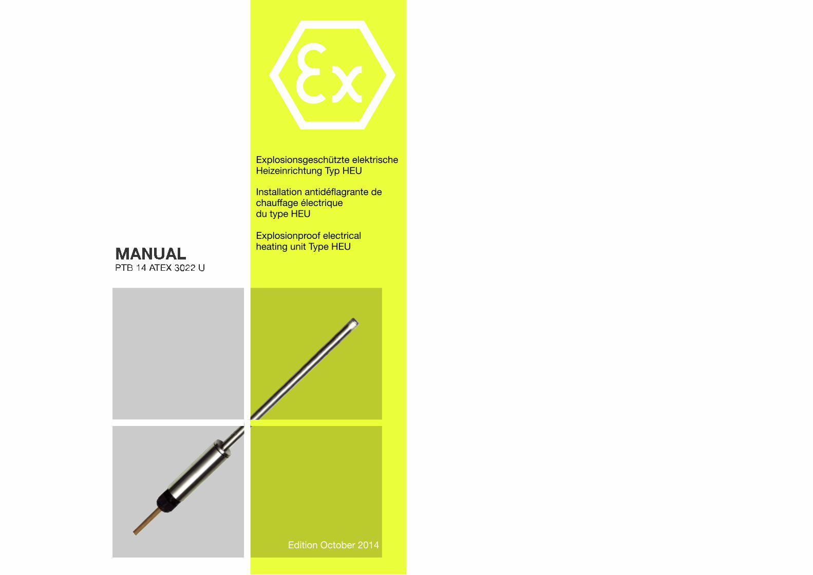
Explosionsgeschützte elektrische Heizeinrichtung Typ HEU
Installation antidéflagrante de chauffage électrique du type HEU
Explosionproof electrical heating unit Type HEU
Edition October 2014
Manual PTB 14 ATEX 3022 U 3
Edition October 2014 thuba Ltd., CH-4015 BaselCopyright Switzerland
Manual PTB 14 ATEX 3022 U 2
Edition October 2014 thuba Ltd., CH-4015 BaselCopyright Switzerland
Explosionsgeschützte elektrische Heizeinrichtung Typ HEU . . . .. . .
Zielgruppe:Erfahrene Elektrofachkräfte gemäss Betriebssi-cherheitsverordnung und unterwiesene Perso-nen.
Inhalt:1. Sicherheitshinweise2. Normenkonformität3. Technische Daten4. Installation5. Erstinbetriebnahme6. Inspektion, Wartung und Instandhaltung7. Entsorgung
1. Sicherheitshinweise
Die Heizeinrichtung dient zur Erwärmungvon Flüssigkeiten, Festkörpern oderGas/Luft-Gemischen.
Die Heizeinrichtung darf in offenen Syste-men nur zur Erwärmung von nicht-brennba-ren und brennbaren Flüssigkeiten mit einemFlammpunkt ≥ 55 °C eingesetzt werden, dienicht über ihren Flammpunkt erwärmt wer-den.
Die Heizeinrichtungen dürfen nicht in der Zone 0eingesetzt werden!
Die Heizeinrichtungen sind auf der Basis derGrunddaten wie
– Umgebungstemperaturbereich– Ein- und Austrittstemperatur des Mediums– Medium mit den physikalischen Stoffdaten
(Wärmeleitfähigkeit, spezifische Wärmeka-pazität, kinematische Viskosität, Prandtl-Zahl, spezifisches Gewicht)
– Temperaturklasse– spezifische Oberflächenbelastung in Ab -
hängigkeit der Stoffdaten des Mediums,der Mediumsgeschwindigkeit, der Span-nung und der zulässigen Oberflächentem-peratur
– Geometrie der Heizeinrichtung (Anordnungder einzelenen Heizelemente, Anströmwin-kel, Wärmeübergang)
Installation antidéflagrante de chauffageélectrique du type HEU . . . .. . .
Groupe ciblé :Électriciens qualifiés selon la réglementationpour la sécurité et la santé et personnel instruit.
Sommaire1. Sécurité 2. Conformité aux normes 3. Caractéristiques techniques 4. Installation5. Première mise en service 6. Inspection, entretien et maintenance7. Élimination
1. Sécurité
L’installation sert au chauffage/réchauffe -ment de liquides et de mélanges gaz/air.
En système ouvert, l’installation ne doit êtreappliquée que pour le chauffage de liquidesincombustibles et combustibles avec unpoint d’inflammation ≥ 55° C qui ne sont paschauffés à une température dépassant leurpoint d’inflammation.
Les installations de chauffage ne doivent pasêtre appliquées dans la zone 0!
Les installations de chauffage sont élaborées enfonction des données de base telles que
– fourchette de température ambiante– températures d’entrée et de sortie du flui-
de traité– caractéristiques physiques du fluide
(conductibilité thermique, capacité ther-mique massique, viscosité cinématique,nombre de Prandtl, poids spécifique)
– classe de température – charge spécifique superficielle dépendant
des caractéristiques de base du fluide,vitesse du fluide, tension et températuresuperficielle tolérées
– Géométrie de l’installation de chauffage(disposition/répartition des corps de chauf-fe, angle d’incidence du fluide, transmis-sion thermique)
Explosionproof electrical heating unitType HEU . . . .. . .
Target group:Experienced electricians as defined by the rele-vant national health and safety at work regula-tions (such as the BetrSichV in Germany) andproperly instructed personnel.
Contents1. Safety instructions2. Conformity with standards3. Technical data4. Installation5. Commissioning6. Inspection, servicing and maintenance7. Disposal
1. Safety instructions
The heating unit is used to heat liquids andgas/air mixtures.
In open systems the heating unit may only beused for heating nonflammable liquids, orflammable liquids with a flash point ≥ 55 °Cthat are not heated above their flash point.
The heating units must not be used in Zone 0!
The heating units are designed specifically forindividual applications on the basis of key proj-ect data such as
– Ambient temperature range– Inlet and outlet temperature of the medium– Medium to be heated, with its physical
properties (thermal conductivity, specificheat capacity, kinematic viscosity, Prandtlnumber, relative density)
– Temperature class– Heat flux, dependent on the physical prop-
erties of the medium, its flow velocity, thesupply voltage and the permissible surfacetemperature
– Geometry of the heating unit (arrangementof the individual heating elements, angle ofincidence, heat transfer)
Manual PTB 14 ATEX 3022 U 5
Edition October 2014 thuba Ltd., CH-4015 BaselCopyright Switzerland
Manual PTB 14 ATEX 3022 U 4
Edition October 2014 thuba Ltd., CH-4015 BaselCopyright Switzerland
The installation requirements to section 4 of thismanual and the commissioning report to IEC60079-14 (section 4.3 ) are prerequisites for sub-sequent safe and trouble-free operation.
After installation the heating unit must besubjected to a final thermal test, since all theconditions impacting on the final specifica-tion of the temperature class will not havebeen known. This thermal test can be carriedout by a qualified assessor (competent per-son) or by the Manufacturer.
No subsequent modifications may be madeto the heating unit or to the associated safe-ty measures.
The heating unit can only be used on anotherapplication with the Manufacturer’s expresswritten approval. A new thermal routine test maybe necessary as appropriate for the applicationconcerned.
Operate the heating units only for their intendedduties in an undamaged condition, and onlywhere the materials of the enclosure and theheating elements are compatible with their envi-ronments.
If the terminal box is not correctly assembled,the minimum degree of protection IP 54, IP 65or IP 66 as per IEC 60529 is no longer guaran-teed.
During operation, do not leave this Manual orany other objects in the terminal box of the heat-ing unit.
Whenever work is done on the heating units,the national safety and accident preventionregulations and the safety instructions givenin this Manual (stated in italics as in thisparagraph) must always be observed!
projektspezifisch auf eine Anwendung ausgelegtworden. Die Errichtungshinweise nach Abschnitt4 dieser Betriebsanleitung und die protokollier-te Erstinbetriebnahme nach EN 60079-14(Abschnitt 4.3) sind Voraussetzungen für einensicheren und ungestörten Betrieb.
Die Heizeinrichtung muss nach der Installa-tion einer thermischen Endprüfung unterzo-gen werden, da für die endgültige Festle-gung der Temperaturklasse nicht alle Rand-bedingungen bekannt waren. Diesethermische Prüfung kann durch einen Sach-verständigen (kompetente Person) oderdurch den Hersteller ausgeführt werden.
Nachträgliche Anpassungen an der Heizein-richtung und an den Schutzmassnahmendürfen nicht vorgenommen werden.
Die Heizeinrichtung kann nur mit einer Freigabedurch den Hersteller für eine andere Anwendungeingesetzt werden. Entsprechend der Anwen-dung kann eine neue thermische Stückprüfungerforderlich werden.
Betreiben Sie die Heizeinrichtungen bestim-mungsgemäss im unbeschädigtem Zustand undnur dort, wo die Beständigkeit der Materialienfür Gehäuse und der Heizelemente gewährleis-tet ist.
Die Mindestschutzart IP 54, IP 65 bwz. IP 66 desAnschlusskastens ist bei nicht korrektemZusammenbau nach EN 60529 nicht mehrgewährleistet.
Lassen Sie diese Betriebsanleitung und andereGegenstände während des Betriebes nicht imAnschlusskasten der Heizeinrichtung liegen.
Beachten Sie bei allen Arbeiten an den Heiz-einrichtungen die nationalen Sicherheits-und Unfallverhütungsvorschriften und dienachfolgenden Sicherheitshinweise in dieserBetriebsanleitung, die wie dieser Text in Kur-sivschrift gefasst sind!
ainsi que de la spécificité du projet et de l’appli-cation. Les instructions d’installation selon lapos. 4 du présent mode d’emploi et du procès-verbal de la 1ère mise en service selon EN60079-14 (pos. 4.3) sont les conditions sine quanon d’une exploitation sûre et sans perturba-tion.
Après le montage, l’installation de chauffagedevra être soumise à une vérification ther-mique finale du fait que toutes les conditionssecondaires pour l’allocation définitive de laclasse de température n’étaient pasconnues. Cet examen terminal peut êtreeffectué par une personne compétente oupar le fabricant.
Aucune modification ultérieure ne doit êtreapportée à l’installation ou aux mesures deprotection.
L’installation de chauffage ne peut être affectéeà une autre utilisation qu’avec l’accord du fabri-cant. Une autre affectation peut en effet néces-siter un nouvel essai thermique individuel.
Utilisez l’installation conformément aux pres-criptions, en état non endommagé uniquementet seulement dans des emplacements où l'inal-térabilité du matériel de l'enveloppe est assurée.
En cas de montage incorrect, l'indice minimalde protection IP 64, IP 65 ou IP 66 selon EN60529 n'est plus garanti.
Ne laissez jamais ce manuel ou d'autres objetsdans l'armoire/le coffret de connexion durant leservice.
Pour tous les travaux touchant l’installationantidéflagrante de chauffage électrique, il ya lieu d'observer les prescriptions nationalesde sécurité et de prévention des accidentsainsi que les indications de la présente noti-ce ayant trait à la sécurité. A l'instar du pré-sent alinéa, ces indications sont impriméesen italique.
Manual PTB 14 ATEX 3022 U 7
Edition October 2014 thuba Ltd., CH-4015 BaselCopyright Switzerland
2. Conformité aux normes
Les installations de chauffage sont conformesaux normes EN 60079-0 et EN 60079-7. Leurdimensionnement répond aux normes indus-trielles EN 60519-1 et EN 60519-2.
Ils ont de plus été développés, fabriqués et tes-tés selon l’état actuel de la technique et confor-mément à la norme ISO 9001:2008.
3. Caractéristiques techniques
3.1 Généralités
Matériaux
Coffrets de connexion:Acier, acier inox, aluminium ou polyesteraCartouches chauffantes:acier inox ou Incoloy 800 selon spécificationdu projet
Température ambiante admise
–20° C à 40° C (standard)–20° C à 60° C (solution particulière)
3.2 Exécution protégée contre les explosions de gaz
Protection antidéflagrante Ex e1 IIC Gb
Indice de protectioncoffret/armoire IP 54, IP 65 ou IP 66
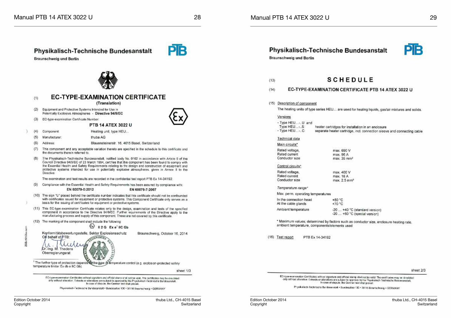
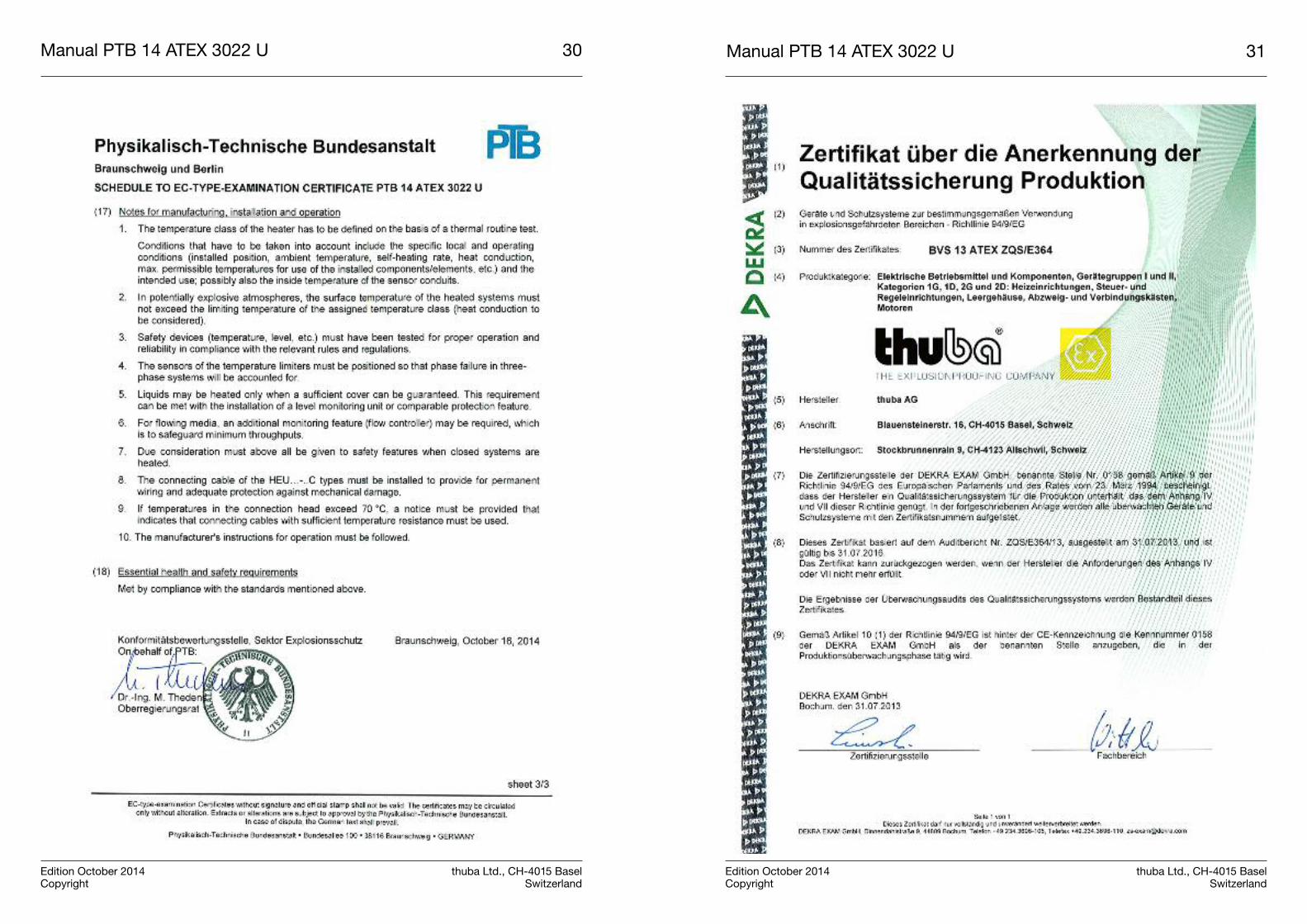
Certificat d'examen de type PTB 14 ATEX 3022 U
3.3 Grandeurs électriques
Valeur de crête du circuit principal:Tension assignée max. 690 V (cf. plaque signalétique)
Courant assigné max. 96 A (cf. plaque signalétique)
1 Die weitere Zündschutzart ist abhängig von der Art der Tem-peraturüberwachung (Beispielsweise explosiongeschützterSicherheitstemperaturbegrenzer Ex db e IIC Gb)
2. Normenkonformität
Die Heizeinrichtungen entsprechen den Explo-sionsschutz-Anforderungen der EN 60079-0und der EN 60079-7. Die Auslegung erfolgtzusätzlich auch nach den Industrienormen EN60519-1 und EN 60519-2.
Diese wurden entsprechend dem Stand derTechnik und gemäss der ISO 9001:2008 entwi-ckelt, gefertigt und geprüft.
3. Technische Daten
3.1 Allgemein
Werkstoffe
Anschlusskasten:Stahl thermolackiert, Edelstahl, Aluminium oderPolyester
Heizstäbe:Edelstahl oder Incoloy 800 nach projekt-spezi-fischer Spezifikation
zul. Umgebungstemperaturen
–20 °C bis 40 °C (Standard)–20 °C bis 60 °C (Sonderausführung)
3.2 Gasexplosionsgeschützte Ausführung
Explosionsschutz Ex e1 IIC Gb
Gehäuseschutzart IP 54, IP 65 bzw. IP 66
EG-Baumusterprüf-bescheinigung PTB 14 ATEX 3022 U
3.3 Elektrische Daten
Höchstwerte der Hauptstromkreise:Bemessungsspannungmax. 690 V (gemäss Typenschild)
Bemessungsstrommax. 96 A (gemäss Typenschild)
1 Die weitere Zündschutzart ist abhängig von der Art der Tem-peraturüberwachung (Beispielsweise explosiongeschützterSicherheitstemperaturbegrenzer Ex db e IIC Gb)
Manual PTB 14 ATEX 3022 U 6
Edition October 2014 thuba Ltd., CH-4015 BaselCopyright Switzerland
2. Conformity with standards
The heating units meet the explosion protectionrequirements of the standards EN 60079-0 andEN 60079-7. The design also complies with thestandards EN 60519-1 and EN 60519-2 con-cerning safety in electroheat installations.
They have been developed, manufactured andinspected using state-of-the-art technology andin compliance with ISO 9001:2008.
3. Technical data
3.1 General
Materials of construction
Terminal boxsteel, stainless steel, aluminum or polyester
Heating elementsstainless steel or Incoloy 800 as per project-specific specifications
Permissible ambient temperatures
–20 °C to 40 °C (standard)–20 °C to 60 °C (special version)
3.2 Version with gas explosion protection
Explosion protection Ex e1 IIC Gb
Enclosure degree of protection IP 54, IP 65 or IP 66
EC type-examination certificate PTB 14 ATEX 3022 U
3.3 Electrical data
Maximum parameters in main circuits:Rated voltagemax. 690 V (as per rating plate)
Rated currentmax. 96 A (as per rating plate)
1 The further type of protection depends on the type of tem-perature control (e.g. explosion-protected safety temperaturelimiter Ex db e IIC Gb)
Manual PTB 14 ATEX 3022 U 9
Edition October 2014 thuba Ltd., CH-4015 BaselCopyright Switzerland
Manual PTB 14 ATEX 3022 U 8
Edition October 2014 thuba Ltd., CH-4015 BaselCopyright Switzerland
Höchstwerte der Steuerstromkreise:Bemessungsspannungmax. 400 V (gemäss Typenschild)
Bemessungsstrommax.16 A (gemäss Typenschild)
max. Leiterquerschnittmax. 4 mm2 (je nach Ausführung
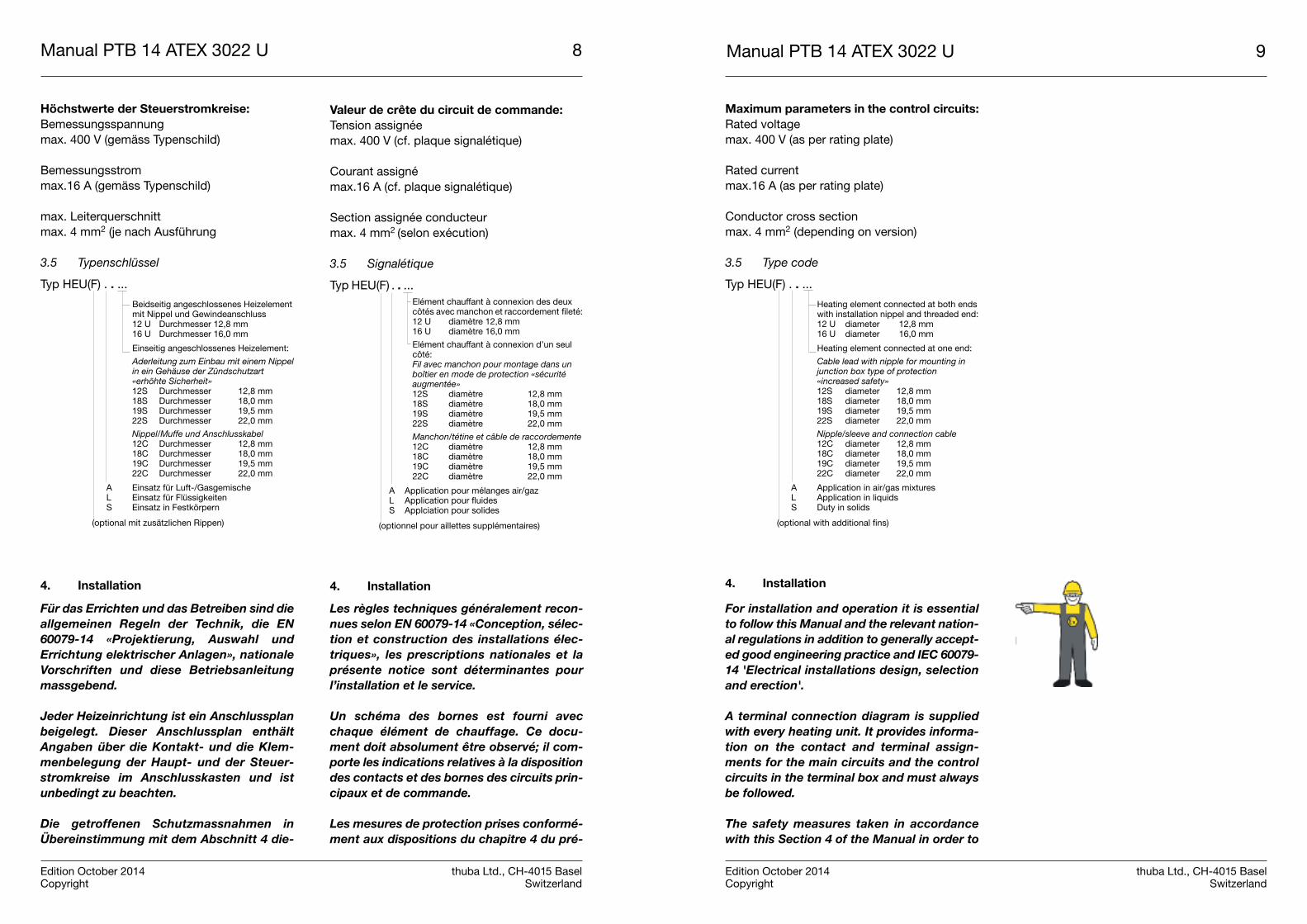
3.5 Typenschlüssel
Typ HEU(F) . . ...
Beidseitig angeschlossenes Heiz elementmit Nippel und Gewinde anschluss12 U Durchmesser 12,8 mm16 U Durchmesser 16,0 mm
Einseitig angeschlossenes Heiz element:
Aderleitung zum Einbau mit einem Nippelin ein Gehäuse der Zündschutzart«erhöhte Sicherheit»12S Durchmesser 12,8 mm18S Durchmesser 18,0 mm19S Durchmesser 19,5 mm22S Durchmesser 22,0 mm
Nippel/Muffe und Anschlusskabel12C Durchmesser 12,8 mm18C Durchmesser 18,0 mm19C Durchmesser 19,5 mm22C Durchmesser 22,0 mm
A Einsatz für Luft-/GasgemischeL Einsatz für FlüssigkeitenS Einsatz in Festkörpern
(optional mit zusätzlichen Rippen)
4. Installation
Für das Errichten und das Betreiben sind dieallgemeinen Regeln der Technik, die EN60079-14 «Projektierung, Auswahl undErrichtung elektrischer Anlagen», nationaleVorschriften und diese Betriebsanleitungmassgebend.
Jeder Heizeinrichtung ist ein Anschlussplanbeigelegt. Dieser Anschlussplan enthältAngaben über die Kontakt- und die Klem-menbelegung der Haupt- und der Steuer-stromkreise im Anschlusskasten und istunbedingt zu beachten.
Die getroffenen Schutzmassnahmen inÜbereinstimmung mit dem Abschnitt 4 die-
Valeur de crête du circuit de commande:Tension assignéemax. 400 V (cf. plaque signalétique)
Courant assigné max.16 A (cf. plaque signalétique)
Section assignée conducteurmax. 4 mm2 (selon exécution)
3.5 Signalétique
Typ HEU(F) . . ... Elément chauffant à connexion des deuxcôtés avec manchon et raccordement fileté:12 U diamètre 12,8 mm16 U diamètre 16,0 mm
Elément chauffant à connexion d’un seulcôté:Fil avec manchon pour montage dans unboîtier en mode de protection «sécuritéaugmentée»12S diamètre 12,8 mm18S diamètre 18,0 mm19S diamètre 19,5 mm22S diamètre 22,0 mm
Manchon/tétine et câble de raccordemente12C diamètre 12,8 mm18C diamètre 18,0 mm19C diamètre 19,5 mm22C diamètre 22,0 mm
A Application pour mélanges air/gazL Application pour fluidesS Applciation pour solides
(optionnel pour aillettes supplémentaires)
4. Installation
Les règles techniques généralement recon-nues selon EN 60079-14 «Conception, sélec-tion et construction des installations élec-triques», les prescriptions nationales et laprésente notice sont déterminantes pourl’installation et le service.
Un schéma des bornes est fourni avecchaque élément de chauffage. Ce docu-ment doit absolument être observé; il com-porte les indications relatives à la dispositiondes contacts et des bornes des circuits prin-cipaux et de commande.
Les mesures de protection prises conformé-ment aux dispositions du chapitre 4 du pré-
Maximum parameters in the control circuits:Rated voltagemax. 400 V (as per rating plate)
Rated currentmax.16 A (as per rating plate)
Conductor cross sectionmax. 4 mm2 (depending on version)
3.5 Type code
Typ HEU(F) . . ...
Heating element connected at both endswith installation nippel and threaded end:12 U diameter 12,8 mm16 U diameter 16,0 mm
Heating element connected at one end:
Cable lead with nipple for mounting injunction box type of protection «increased safety»12S diameter 12,8 mm18S diameter 18,0 mm19S diameter 19,5 mm22S diameter 22,0 mm
Nipple/sleeve and connection cable12C diameter 12,8 mm18C diameter 18,0 mm19C diameter 19,5 mm22C diameter 22,0 mm
A Application in air/gas mixturesL Application in liquidsS Duty in solids
(optional with additional fins)
4. Installation
For installation and operation it is essentialto follow this Manual and the relevant nation-al regulations in addition to generally accept-ed good engineering practice and IEC 60079-14 'Electrical installations design, selectionand erection'.
A terminal connection diagram is suppliedwith every heating unit. It provides informa-tion on the contact and terminal assign-ments for the main circuits and the controlcircuits in the terminal box and must alwaysbe followed.
The safety measures taken in accordancewith this Section 4 of the Manual in order to
Manual PTB 14 ATEX 3022 U 11
Edition October 2014 thuba Ltd., CH-4015 BaselCopyright Switzerland
Manual PTB 14 ATEX 3022 U 10
Edition October 2014 thuba Ltd., CH-4015 BaselCopyright Switzerland
ser Betriebsanleitung für das Betreiben vonHeizeinrichtungen in explosionsgefährdetenBereichen müssen im Elektroschema derAnlage ersichtlich sein.
Die auf dem Typenschild angegebenenNenn daten der Heizeinrichtung und die mög-lichen zusätzlichen Herstellerangaben müs-sen berücksichtigt werden.
4.1 Umgebungstemperatur
Zur Einhaltung der zulässigen maximalen Ober-flächentemperatur darf die Umgebungstempe-ratur den Bereich von –20°C bis 40°C bzw. 60°C(siehe Typenschild) nicht unter- bzw. über-schreiten. Zu beachten sind bei der Be trachtungder Temperaturverhältnisse auch Einflüsse vonweiteren vorhandenen Wärmequellen (Prozess-wärme). Diese dürfen nicht zu einer zusätzlichenErwärmung des An schluss kastens führen.Die Wärmeabgabe (primär durch Konvektion)des Anschlusskastens und des unbeheiztenEndes zwischen Anschlusskasten und Flanschdarf nicht behindert werden. Thermische Isola-tionen dürfen nicht dicht an den Anschlusskas-ten geführt werden. Falls Leitbleche für dieUnterstützung der Konvektion hinter demFlansch angebracht sind, dürfen diese nichtdurch die Isolation abgedeckt werden.
4.2 Elektrische Schutzmassnahmen
4.2.1 Überstromauslöser
Der Nennauslösestrombereich des Überstrom-schutzes ist auf den Nennstrom der Heizein-richtung wie auf dem Typenschild bzw. wie inder Spezifikation der Heizeinrichtung angege-ben abzustimmen. Vorzugsweise wird eine Aus-lösecharakteristik C gewählt.
4.2.2 Fehlerstromschutzschalter und Isolationsüberwachung(EN 60079-14:2014 Absatz 13)
Zur Begrenzung der Erwärmung infolge anoma-ler Erdschluss- und Erdableitströme musszusätzlich zum Überstromschutz folgendeSchutzeinrichtung installiert sein:
sent mode d’emploi pour le service de l’ins-tallation de chauffage en emplacement dan-gereux doivent être visibles sur le schémaélectrique du système.
Les caractéristiques nominales figurant surla plaque signalétique ainsi que les éven-tuelles données complémentaires doiventégalement être prises en considération.
4.1 Température ambiante
Afin d'assurer les températures de surfaceadmissibles, la température ambiante de –20°Cà 40°C à savoir 60°C (voir plaquette signalé-tique) doit être maintenue. Il faut, dans lesconsidérations relatives à la température, tenirégalement compte d'autres sources de chaleurde même que de l'insolation et des éventuellespuissances de coupure élevées en service tem-poraire. Ces facteurs ne doivent pas contribuerà une surchauffe du boîtier de connexion. L’émission de chaleur (en premier lieu deconvection) du boîtier de connexion et de l’ex-trémité non chauffée entre le boîtier deconnexion et la bride ne doit pas être entravée.Les isolations thermiques ne doivent pas être àproximité immédiate du boîtier de connexion. Sides déflecteurs de renforcement de la convec-tion sont disposés derrière la bride, ils ne doi-vent pas être recouverts par l’isolation.
4.2 Mesures de sécurité électriques
4.2.1 Discontacteur
La zone de courant de déclenchement nominaldu discontacteur doit être conforme aux spéci-fications du système de chauffage, à savoir figu-rant sur la plaque signalétique. Nous recom-mandons la sélection d’une caractéristique dedéclenchement C.
4.2.2 Interrupteur différentiel contre les cou-rants de court-circuit et contrôleurd'isole ment (EN 60079-14:2014 section 13)
De manière à limiter l’échauffement dû auxdéfauts de mise à la terre et aux courants de fui-te anormaux, la protection supplémentaire sui-vante doit être installée:
operate heating units in hazardous areasmust be shown in the circuit diagram for thesystem.
The design data for the heating unit statedon its rating plate and any additional dataprovided by the Manufacturer must alwaysbe taken into account.
4.1 Ambient temperature
To keep the surface temperature below the per-missible maximum, it must be ensured that theambient temperature remains within the range–20°C to 40°C or 60°C (see rating plate). Theeffects of other local heat sources (process heat)must also be taken into account and must notcause an additional rise in the terminal box tem-perature.There must be no restrictions on the dissipationof heat (primarily by convection) from the termi-nal box and the unheated end of the unitbetween the terminal box and the flange. Thethermal insulation must therefore not be fittedright up to the terminal box. If baffles are fittedbehind the flange to aid convection, these mustnot be covered by the insulation either.
4.2 Electrical safety measures
4.2.1 Overcurrent protection
The rated tripping range of the circuit breakermust be selected as appropriate for the ratedcurrent of the heating unit as stated on its ratingplate or in its specifications. The circuit breakershould preferably have the tripping characteris-tic C.
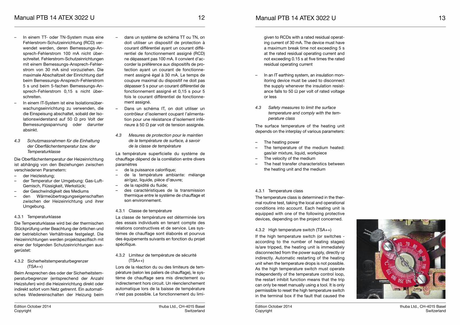
4.2.2 Residual current device and insulationmonitoring (IEC60079-14:2014clause 13)
In order to limit the heating effect due to abnor-mal ground fault and earth leakage currents, thefollowing must be installed (in addition to over-current protection):
– In a type TT or TN earthing system, a resid-ual current device (RCD) with a rated resid-ual operating current not exceeding 100mA must be used. Preference should be
Manual PTB 14 ATEX 3022 U 13
Edition October 2014 thuba Ltd., CH-4015 BaselCopyright Switzerland
Manual PTB 14 ATEX 3022 U 12
Edition October 2014 thuba Ltd., CH-4015 BaselCopyright Switzerland
– In einem TT- oder TN-System muss eineFehlerstrom-Schutzeinrichtung (RCD) ver-wendet werden, deren Bemessungs-An -sprech-Fehlerstrom 100 mA nicht über-schreitet. Fehlerstrom-Schutzeinrichtungenmit einem Bemessungs-Ansprech-Fehler-strom von 30 mA sind vorzuziehen. Diemaximale Abschaltzeit der Einrichtung darfbeim Bemessungs-Ansprech-Fehlerstrom5 s und beim 5-fachen Bemessungs-An -sprech-Fehlerstrom 0,15 s nicht über-schreiten.
– In einem IT-System ist eine Isolationsüber-wachungseinrichtung zu verwenden, diedie Einspeisung abschaltet, sobald der Iso-lationswiderstand auf 50 Ω pro Volt derBemessungsspannung oder darunterabsinkt.
4.3 Schutzmassnahmen für die Einhaltungder Oberflächentemperatur bzw. derTemperaturklasse
Die Oberflächentemperatur der Heizeinrichtungist abhängig von den Beziehungen zwischenverschiedenen Parametern:– der Heizleistung;– der Temperatur der Umgebung: Gas-Luft-
Gemisch, Flüssigkeit, Werkstück;– der Geschwindigkeit des Mediums– den Wärmeübertragungseigenschaften
zwischen der Heizeinrichtung und ihrerUmgebung.
4.3.1 Temperaturklasse
Die Temperaturklasse wird bei der thermischenStückprüfung unter Beachtung der örtlichen undder betrieblichen Verhältnisse festgelegt. DieHeizeinrichtungen werden projektspezifisch miteiner der folgenden Schutzeinrichtungen aus-gerüstet:
4.3.2 Sicherheitstemperaturbegrenzer(TSA++)
Beim Ansprechen des oder der Sicherheitstem-peraturbegrenzer (entsprechend der AnzahlHeizstufen) wird die Heizeinrichtung direkt oderindirekt sofort vom Netz getrennt. Ein automati-sches Wiedereinschalten der Heizung beim
– dans un système de schéma TT ou TN, ondoit utiliser un dispositif de protection àcourant différentiel ayant un courant diffé-rentiel de fonctionnement assigné (RCD)ne dépassant pas 100 mA. Il convient d’ac-corder la préférence aux dispositifs de pro-tection ayant un courant de fonctionne-ment assigné égal à 30 mA. Le temps decoupure maximal du dispositif ne doit pasdépasser 5 s pour un courant différentiel defonctionnement assigné et 0,15 s pour 5fois le courant différentiel de fonctionne-ment assigné.
– Dans un schéma IT, on doit utiliser uncontrôleur d’isolement coupant l’alimenta-tion pour une résistance d’isolement infé-rieure à 50 Ω par volt de tension assignée.
4.3 Mesures de protection pour le maintiende la température de surface, à savoirde la classe de température
La température superficielle du système dechauffage dépend de la corrélation entre diversparamètres– de la puissance calorifique;– de la température ambiante: mélange
air/gaz, liquide, pièce d’œuvre;– de la rapidité du fluide; – des caractéristiques de la transmission
thermique entre le système de chauffage etson environnement.
4.3.1 Classe de température
La classe de température est déterminée lorsdes essais individuels en tenant compte desrelations constructives et de service. Les sys-tèmes de chauffage sont élaborés et pourvusdes équipements suivants en fonction du projetspécifique.
4.3.2 Limiteur de température de sécurité(TSA++)
Lors de la réaction du ou des limiteurs de tem-pérature (selon les paliers de chauffage), le sys-tème de chauffage sera mis directement ouindirectement hors circuit. Un réenclenchementautomatique lors de la baisse de températuren’est pas possible. Le fonctionnement du limi-
given to RCDs with a rated residual operat-ing current of 30 mA. The device must havea maximum break time not exceeding 5 sat the rated residual operating current andnot exceeding 0.15 s at five times the ratedresidual operating current
– In an IT earthing system, an insulation mon-itoring device must be used to disconnectthe supply whenever the insulation resist-ance falls to 50 Ω per volt of rated voltageor less
4.3 Safety measures to limit the surfacetemperature and comply with the tem-perature class
The surface temperature of the heating unitdepends on the interplay of various parameters:
– The heating power– The temperature of the medium heated:
gas/air mixture, liquid, workpiece– The velocity of the medium– The heat transfer characteristics between
the heating unit and the medium
4.3.1 Temperature class
The temperature class is determined in the ther-mal routine test, taking the local and operationalconditions into account. Each heating unit isequipped with one of the following protectivedevices, depending on the project concerned.
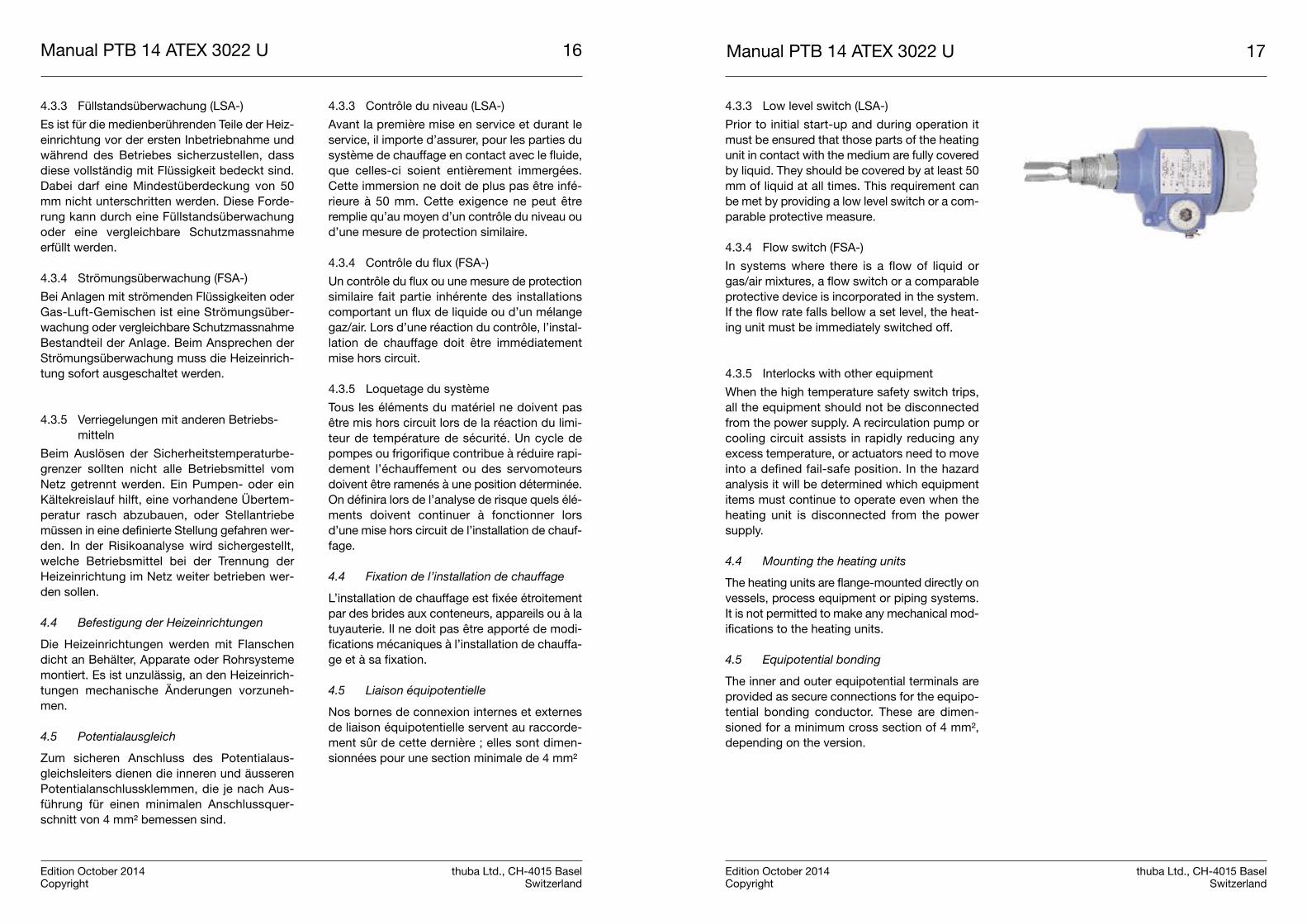
4.3.2 High temperature switch (TSA++)
If the high temperature switch (or switches -according to the number of heating stages)is/are tripped, the heating unit is immediatelydisconnected from the power supply, directly orindirectly. Automatic restarting of the heatingunit when the temperature drops is not possible.As the high temperature switch must operateindependently of the temperature control loop,the restart inhibit function means that the tripcan only be reset manually using a tool. It is onlypermissible to reset the high temperature switchin the terminal box if the fault that caused the

Manual PTB 14 ATEX 3022 U 15
Edition October 2014 thuba Ltd., CH-4015 BaselCopyright Switzerland
Manual PTB 14 ATEX 3022 U 14
Edition October 2014 thuba Ltd., CH-4015 BaselCopyright Switzerland
Absinken der Temperatur ist nicht möglich. DerSicherheitstemperaturbegrenzer muss unab-hängig vom Betrieb der Temperaturregeleinrich-tung sein. Die Wiedereinschaltsperre darf nurvon Hand unter Verwendung eines Werkzeugesrückstellbar sein. Die Rückstelleinrichtung desSicherheitstemperaturbegrenzers im Anschluss-kasten darf nur dann betätigt werden, wenn derFehlerzustand für die Auslösung behoben istund zusätzlich die festgelegten Prozessbedin-gungen wieder erlangt wurden. Die Einstellungder Sicherheitstemperaturbegrenzer muss gesi-chert sein und darf im Betrieb nicht nachträglichverändert werden. Dies kann erreicht werden,indem der Einstellbereich des Sicherheitstem-peraturbegrenzers auf die höchste Nennauslö-setemperatur der jeweiligen Temperaturklasseausgelegt wird. Stimmt der Einstellbereich nichtmit der Temperaturklasse überein, wird derSicherheitstemperaturbegrenzer nach derStückprüfung plombiert.
Neben der Oberflächentempertur oder derunmittelbaren Umgebung des Heizelementeskönnen auch andere oder zusätzliche Parame-ter (beispielsweise der Füllstand, der Durchfluss,der Strom oder die Leistungsaufnahme) über-wacht werden
Tabelle 1: Forderungen an die Sicherheitstemperatur-begrenzer
teur de température doit être autonome, c’est-à-dire indépendant du fonctionnement du sys-tème de chauffage. Le dispositif de redémarra-ge ne peut être enclenché que manuellement àl’aide d’un outil approprié. Le dispositif de réar-mement du limiteur de température intégré aucoffret de connexion ne doit être manipulé quelorsque l’état de défaut aura été rectifié et unefois les conditions de service définies rétablies.La mise au point du limiteur de température desécurité doit être assurée et ne doit pas êtremodifiée ultérieurement, durant le processus.Ceci peut être obtenu en réglant le limiteur surle plus haut degré de température nominale dedéclenchement de la classe de températurecorrespondante. Si la plage de réglage ne cor-respond pas à la classe de température, le limi-teur sera plombé après l’essai individuel.
Outre la température de surface et la tempéra-ture de proximité immédiate des élémentschauffants, d’autres paramètres ou des para-mètres complémentaires peuvent ou doiventêtre contrôlés, par exemple le niveau, l’écoule-ment, le flux ou la puissance absorbée.
Tableau 1: Exigences relatives au limiteur de tempéra-ture de sécurité
trip has been rectified and the specified processconditions have also been restored. The settingsof the high temperature switches must besecure and they must not be changed later inoperation. This can be achieved by selecting thesetting range of the high temperature switch sothat the maximum tripping temperature corre-sponds to the temperature class concerned. Ifthe setting range does not correspond to thetemperature class, the high temperature switchmust be protected with a tamper-evident sealafter the routine test.
In addition to the surface temperature and theimmediate environment of the heating element,other parameters or additional ones (such aslevel, flow rate, current or power draw) can alsobe monitored.
Table 1: Requirements for the high temperature safety switch
Elektromechanischer Sicher-heitstemperaturbegrenzer
Prozessorgesteuerter Sicher-heitstemperaturbegrenzer
Rückstellung nur mit WerkzeugRückstellung nur mit User-Code
Rückstellung von HandRückstellung nur durch autori-siertes Personal im Elektroraum
Rückstellung nur unter norma-len Betriebsbedingungen
Rückstellung nur unter norma-len Betriebsbedingungen
Gesicherte Einstellung
Einstellung der Temperatur-klasse nur mit Hardware-Brücke und Hersteller-Codemöglich
Unabhängigkeit von der Rege-lung
Unabhängigkeit von der Regelung
Fühlerausfallsicherung(Kapillarrohrbruchsicherung)
Fühlerüberwachung 100%
Funktionsprüfung nach EN60730 Teil 1 sowie Teile 2–9
Funktionsprüfung
Limiteur de température desécurité électromécanique
Limiteur de température desécurité piloté par processeur
Réarmement avec outil uniquement
Réarmement moyennant coded’utilisateur uniquement
Réarmement manuelRéarmement par personnelautorisé à accéder dans le localélectrotechnique uniquement
Réarmement en conditions nor-males de service uniquement
Réarmement en conditions nor-males de service uniquement
Réglage assuréRéglage de température possible uniquement avec passerelle et code fabricant
Autonomie de réglage Autonomie de réglage
Sûreté du capteur intégrée (protection rupture du tubecapillaire)
Contrôle du capteur 100 %
Mise au point du fonctionne-ment selon EN 60730, partie 1ainsi que parties 2 à 9
Mise au point du fonctionnement
Electromechanical high temperature switch
Processor-controlled high temperature switch
Resetting only with toolResetting only possible withuser code
Manual resettingResetting only by authorizedpersonnel in control cabinet
Resetting only under normal operating conditions
Resetting only under normal operating conditions
Tamperproof setting
Setting of temperature classonly possible with hard-wiredjumper and Manufacturer’scode
Independent of the controller Independent of the controller
Sensor fail-safe function (ifcapillary tube fractures)
100% sensor monitoring
Functional test to IEC 60730Part 1 and Parts 2–9
Functional test
Manual PTB 14 ATEX 3022 U 17
Edition October 2014 thuba Ltd., CH-4015 BaselCopyright Switzerland
Manual PTB 14 ATEX 3022 U 16
Edition October 2014 thuba Ltd., CH-4015 BaselCopyright Switzerland
4.3.3 Füllstandsüberwachung (LSA-)
Es ist für die medienberührenden Teile der Heiz-einrichtung vor der ersten Inbetriebnahme undwährend des Betriebes sicherzustellen, dassdiese vollständig mit Flüssigkeit bedeckt sind.Dabei darf eine Mindestüberdeckung von 50mm nicht unterschritten werden. Diese Forde-rung kann durch eine Füllstandsüberwachungoder eine vergleichbare Schutzmassnahmeerfüllt werden.
4.3.4 Strömungsüberwachung (FSA-)
Bei Anlagen mit strömenden Flüssigkeiten oderGas-Luft-Gemischen ist eine Strömungsüber-wachung oder vergleichbare SchutzmassnahmeBestandteil der Anlage. Beim Ansprechen derStrömungsüberwachung muss die Heizeinrich-tung sofort ausgeschaltet werden.
4.3.5 Verriegelungen mit anderen Betriebs-mitteln
Beim Auslösen der Sicherheitstemperaturbe-grenzer sollten nicht alle Betriebsmittel vomNetz getrennt werden. Ein Pumpen- oder einKältekreislauf hilft, eine vorhandene Übertem-peratur rasch abzubauen, oder Stellantriebemüssen in eine definierte Stellung gefahren wer-den. In der Risikoanalyse wird sichergestellt,welche Betriebsmittel bei der Trennung derHeizeinrichtung im Netz weiter betrieben wer-den sollen.
4.4 Befestigung der Heizeinrichtungen
Die Heizeinrichtungen werden mit Flanschendicht an Behälter, Apparate oder Rohrsystememontiert. Es ist unzulässig, an den Heizeinrich-tungen mechanische Änderungen vorzuneh-men.
4.5 Potentialausgleich
Zum sicheren Anschluss des Potentialaus-gleichsleiters dienen die inneren und äusserenPotentialanschlussklemmen, die je nach Aus-führung für einen minimalen Anschlussquer-schnitt von 4 mm² bemessen sind.
4.3.3 Contrôle du niveau (LSA-)
Avant la première mise en service et durant leservice, il importe d’assurer, pour les parties dusystème de chauffage en contact avec le fluide,que celles-ci soient entièrement immergées.Cette immersion ne doit de plus pas être infé-rieure à 50 mm. Cette exigence ne peut êtreremplie qu’au moyen d’un contrôle du niveau oud’une mesure de protection similaire.
4.3.4 Contrôle du flux (FSA-)
Un contrôle du flux ou une mesure de protectionsimilaire fait partie inhérente des installationscomportant un flux de liquide ou d’un mélangegaz/air. Lors d’une réaction du contrôle, l’instal-lation de chauffage doit être immédiatementmise hors circuit.
4.3.5 Loquetage du système
Tous les éléments du matériel ne doivent pasêtre mis hors circuit lors de la réaction du limi-teur de température de sécurité. Un cycle depompes ou frigorifique contribue à réduire rapi-dement l’échauffement ou des servomoteursdoivent être ramenés à une position déterminée.On définira lors de l’analyse de risque quels élé-ments doivent continuer à fonctionner lorsd’une mise hors circuit de l’installation de chauf-fage.
4.4 Fixation de l’installation de chauffage
L’installation de chauffage est fixée étroitementpar des brides aux conteneurs, appareils ou à latuyauterie. Il ne doit pas être apporté de modi-fications mécaniques à l’installation de chauffa-ge et à sa fixation.
4.5 Liaison équipotentielle
Nos bornes de connexion internes et externesde liaison équipotentielle servent au raccorde-ment sûr de cette dernière ; elles sont dimen-sionnées pour une section minimale de 4 mm²
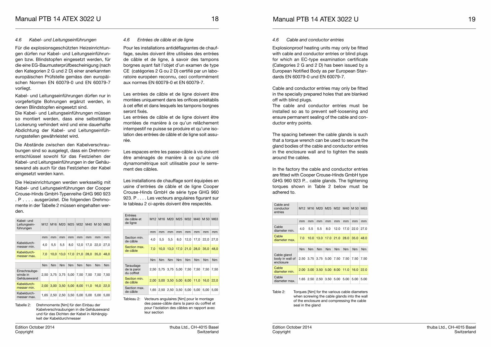
4.3.3 Low level switch (LSA-)
Prior to initial start-up and during operation itmust be ensured that those parts of the heatingunit in contact with the medium are fully coveredby liquid. They should be covered by at least 50mm of liquid at all times. This requirement canbe met by providing a low level switch or a com-parable protective measure.
4.3.4 Flow switch (FSA-)
In systems where there is a flow of liquid orgas/air mixtures, a flow switch or a comparableprotective device is incorporated in the system.If the flow rate falls bellow a set level, the heat-ing unit must be immediately switched off.
4.3.5 Interlocks with other equipment
When the high temperature safety switch trips,all the equipment should not be disconnectedfrom the power supply. A recirculation pump orcooling circuit assists in rapidly reducing anyexcess temperature, or actuators need to moveinto a defined fail-safe position. In the hazardanalysis it will be determined which equipmentitems must continue to operate even when theheating unit is disconnected from the powersupply.
4.4 Mounting the heating units
The heating units are flange-mounted directly onvessels, process equipment or piping systems.It is not permitted to make any mechanical mod-ifications to the heating units.
4.5 Equipotential bonding
The inner and outer equipotential terminals areprovided as secure connections for the equipo-tential bonding conductor. These are dimen-sioned for a minimum cross section of 4 mm²,depending on the version.
Manual PTB 14 ATEX 3022 U 19
Edition October 2014 thuba Ltd., CH-4015 BaselCopyright Switzerland
Manual PTB 14 ATEX 3022 U 18
Edition October 2014 thuba Ltd., CH-4015 BaselCopyright Switzerland
4.6 Kabel- und Leitungseinführungen
Für die explosionsgeschützten Heizeinrichtun-gen dürfen nur Kabel- und Leitungseinführun-gen bzw. Blindstopfen eingesetzt werden, fürdie eine EG-Baumusterprüfbescheinigung (nachden Kategorien 2 G und 2 D) einer anerkannteneuropäischen Prüfstelle gemäss den europäi-schen Normen EN 60079-0 und EN 60079-7vorliegt.
Kabel- und Leitungseinführungen dürfen nur invorgefertigte Bohrungen ergänzt werden, indenen Blindstopfen eingesetzt sind.Die Kabel- und Leitungseinführungen müssenso montiert werden, dass eine selbsttätigeLockerung verhindert wird und eine dauerhafteAbdichtung der Kabel- und Leitungseinfüh-rungsstellen gewährleistet wird.
Die Abstände zwischen den Kabelverschrau-bungen sind so ausgelegt, dass ein Drehmom-entschlüssel sowohl für das Festziehen derKabel- und Leitungseinführungen in der Gehäu-sewand als auch für das Festziehen der Kabeleingesetzt werden kann.
Die Heizeinrichtungen werden werksseitig mitKabel- und Leitungseinführungen der CooperCrouse-Hinds GmbH-Typenreihe GHG 960 923. P . . . . ausgerüstet. Die folgenden Drehmo-mente in der Tabelle 2 müssen eingehalten wer-den.
Tabelle 2: Drehmomente [Nm] für den Einbau derKabelverschraubungen in die Gehäusewandund für das Dichten der Kabel in Abhängig-keit der Kabeldurchmesser
4.6 Entrées de câble et de ligne
Pour les installations antidéflagrantes de chauf-fage, seules doivent être utilisées des entréesde câble et de ligne, à savoir des tamponsborgnes ayant fait l’objet d’un examen de typeCE (catégories 2 G ou 2 D) certifié par un labo-ratoire européen reconnu, ceci conformémentaux normes EN 60079-0 et EN 60079-7.
Les entrées de câble et de ligne doivent êtremontées uniquement dans les orifices préétablisà cet effet et dans lesquels les tampons borgnesseront fixés. Les entrées de câble et de ligne doivent êtremontées de manière à ce qu’un relâchementintempestif ne puisse se produire et qu’une iso-lation des entrées de câble et de ligne soit assu-rée.
Les espaces entre les passe-câble à vis doiventêtre aménagés de manière à ce qu’une clédynamométrique soit utilisable pour le serre-ment des câbles.
Les installations de chauffage sont équipées enusine d’entrées de câble et de ligne CooperCrouse-Hinds GmbH de série type GHG 960923. P . . . . Les vecteurs angulaires figurant surle tableau 2 ci-après doivent être respectés.
Tableau 2: Vecteurs angulaires [Nm] pour le montagedes passe-câble dans la paroi du coffret etpour l’isolation des câbles en rapport avecleur section
4.6 Cable and conductor entries
Explosionproof heating units may only be fittedwith cable and conductor entries or blind plugsfor which an EC-type examination certificate(Categories 2 G and 2 D) has been issued by aEuropean Notified Body as per European Stan-dards EN 60079-0 und EN 60079-7.
Cable and conductor entries may only be fittedin the specially prepared holes that are blankedoff with blind plugs.The cable and conductor entries must beinstalled so as to prevent self-loosening andensure permanent sealing of the cable and con-ductor entry points.
The spacing between the cable glands is suchthat a torque wrench can be used to secure thegland bodies of the cable and conductor entriesin the enclosure wall and to tighten the sealsaround the cables.
In the factory the cable and conductor entriesare fitted with Cooper Crouse-Hinds GmbH typeGHG 960 923 P... cable glands. The tighteningtorques shown in Table 2 below must beadhered to.
Table 2: Torques [Nm] for the various cable diameterswhen screwing the cable glands into the wallof the enclosure and compressing the cableseal in the gland
Kabel- und Leitungsein-führungen
M12 M16 M20 M25 M32 M40 M 50 M63
mm mm mm mm mm mm mm mm
Kabeldurch-messer min. 4,0 5,5 5,5 8,0 12,0 17,0 22,0 27,0
Kabeldurch-messer max. 7,0 10,0 13,0 17,0 21,0 28,0 35,0 48,0
Nm Nm Nm Nm Nm Nm Nm Nm
Einschraubge-winde inGehäusewand
2,50 3,75 3,75 5,00 7,50 7,50 7,50 7,50
Kabeldurch-messer min. 2,00 3,00 3,50 5,00 8,00 11,0 16,0 22,0
Kabeldurch-messer max. 1,65 2,50 2,50 3,50 5,00 5,00 5,00 5,00
Entrées de câble et de ligne
M12 M16 M20 M25 M32 M40 M 50 M63
mm mm mm mm mm mm mm mm
Section min. de câble 4,0 5,5 5,5 8,0 12,0 17,0 22,0 27,0
Section max.de câble 7,0 10,0 13,0 17,0 21,0 28,0 35,0 48,0
Nm Nm Nm Nm Nm Nm Nm Nm
Taraudage de la paroi du coffret
2,50 3,75 3,75 5,00 7,50 7,50 7,50 7,50
Section min. de câble 2,00 3,00 3,50 5,00 8,00 11,0 16,0 22,0
Section max. de câble 1,65 2,50 2,50 3,50 5,00 5,00 5,00 5,00
Cable and conductorentries
M12 M16 M20 M25 M32 M40 M 50 M63
mm mm mm mm mm mm mm mm
Cable diameter min. 4.0 5.5 5.5 8.0 12.0 17.0 22.0 27.0
Cable diameter max. 7.0 10.0 13.0 17.0 21.0 28.0 35.0 48.0
Nm Nm Nm Nm Nm Nm Nm Nm
Cable glandbody in wall ofenclosure
2.50 3.75 3.75 5.00 7.50 7.50 7.50 7.50
Cable diameter min. 2.00 3.00 3.50 5.00 8.00 11.0 16.0 22.0
Cable diameter max. 1.65 2.50 2.50 3.50 5.00 5.00 5.00 5.00
Manual PTB 14 ATEX 3022 U 21
Edition October 2014 thuba Ltd., CH-4015 BaselCopyright Switzerland
Manual PTB 14 ATEX 3022 U 20
Edition October 2014 thuba Ltd., CH-4015 BaselCopyright Switzerland
Werden andere Kabel- und Leitungseinführun-gen eingebaut, müssen die Drehmomente unddie zugehörigen Kabeldurchmesser der ent-sprechenden Betriebsanleitung des jeweiligenHerstellers entnommen werden.
Eigensichere Stromkreise müssen über separa-te Leitungseinführungen hinein- und herausge-führt werden, die (beispielsweise mit hellblauerFarbe) besonders gekennzeichnet sind.
Wenn Kabel- und Leitungseinführungen entfal-len oder nicht belegt sind, müssen die Bohrun-gen mit Blindstopfen und nicht verwendeteKabeleinführungen mit den zugehörigen Ver-schlussstopfen verschlossen werden.
5. Erstinbetriebnahme
Siehe auch Erstprüfung gemäss EN 60079-14,«Projektierung, Auswahl und Errichtung elektri-scher Anlagen», Abschnitt 4.3.
Bevor die Heizeinrichtung in Betrieb genommenwird, muss eine Erstprüfung erfolgen. Dieseumfasst die Vollständigkeit der getroffenenSchutzmassnahmen und deren Wirkungsam-keit. Die Resultate der Erstinbetriebsetzung sindaufzuzeichnen.
6. Inspektion, Wartung und Instandhaltung
Die für die Inspektion, die Wartung und dieInstandsetzung geltenden Bestimmungender EN 60079-17, «Prüfung und Instandhal-tung elektrischer Anlagen in explosionsge-fährdeten Bereichen», sind einzuhalten. ImRahmen der Inspektionen und der Wartungsind vor allem Teile zu prüfen, von denen dieZündschutzart abhängt.
Es dürfen nur Originalersatzteile des Herstellerseingesetzt werden.
Si d’autres câbles et lignes sont montés, lesvecteurs angulaires et les sections des câblesdevront être définis en consultant les modesd’emploi de chacun des fabricants concernés.
Les circuits électriques à sécurité intrinsèquedoivent faire l’objet d’entrées et de sorties sépa-rées signalées spécialement (par exemple enbleu clair).
Lorsque des entrées de câble ou de ligne s’avè-rent superflues ou ne sont pas utilisées, les ori-fices inutilisés devront être fermés par des tam-pons borgnes appropriés.
5. Première mise en service
Consulter également la première mise en servi-ce selon EN 60079-14 «Conception, sélection etconstruction des installations électriques»,,chap. 4.3.
Une inspection initiale de l’installation antidéfla-grante de chauffage doit être effectuée avant lapremière mise en service. Celle-ci comprendl’ensemble des mesures de protection et leurefficacité. Les résultats doivent faire l’objet d’undocument.
6. Inspection, entretien et maintenance
Les prescriptions de la norme EN 60079-17«Inspection et entretien des installationsélectriques en atmosphères explosibles»doivent être respectées en ce qui concerneles inspections, l’entretien et la maintenancede l’installation. Dans le cadre des inspec-tions et de la maintenance, il est en premierlieu nécessaire de vérifier toutes les partiesdont dépend le mode de protection.
Seules les pièces de rechange originales four-nies par le fabricant doivent être utilisées.
If other cable and conductor entries areinstalled, the torques required and the corre-sponding cable diameters will be found in themanual of the manufacturer concerned.
Intrinsically safe circuits must enter and leavethe enclosure via separate cable entries that arespecially marked, for example with a light bluecolor.
If any cable and conductor entries are not usedor are no longer needed, the tapped holes andredundant gland bodies must be blanked offwith suitable blind plugs or caps.
5. Commissioning
Please also refer to the information on the initialinspection given in IEC 60079-14 'Electricalinstallations design, selection and erection',subclause 4.3.
Before the heating unit is commissioned, an ini-tial inspection must be carried out. This consistsof verifying the completeness of the safetymeasures taken and their efficacy. The results ofthe first system start-up must be recorded.
6. Inspection, servicing and maintenance
The provisions of IEC 60079-17 'Inspectionand maintenance of electrical installations inhazardous areas' relating to inspection, serv-icing and maintenance must be compliedwith. In the course of inspections and main-tenance work, those components on whichthe type of explosion protection is depend-ent must be inspected particularly carefully.
Only genuine spare parts from the Manufactur-er may be installed.
Manual PTB 14 ATEX 3022 U 23
Edition October 2014 thuba Ltd., CH-4015 BaselCopyright Switzerland
Manual PTB 14 ATEX 3022 U 22
Edition October 2014 thuba Ltd., CH-4015 BaselCopyright Switzerland
6.1 Qualifikation
Die Prüfung, die Wartung und die Instandset-zung der Anlagen darf nur von erfahrenem Per-sonal ausgeführt werden, dem bei der Ausbil-dung auch Kenntnisse über die verschiedenenZündschutzarten und Installationsverfahren, ein-schlägigen Regeln und Vorschriften sowie dieallgemeinen Grundsätze der Bereichseinteilungvermittelt wurden. Eine angemessene Weiterbil-dung oder Schulung ist für das Personal regel-mässig durchzuführen.
6.2 Erneute Inbetriebnahme
Vor einer erneuten Inbetriebnahme der explo -sionsgeschützten Heizeinrichtungen ist zu über-prüfen, dass die getroffenen Schutzmassnah-men wirksam sind. Werden Defekte an An-schlusskästen, Kabeln oder deren Einführungenfestgestellt, dürfen die explosionsgeschütztenHeizeinrichtungen nicht mehr eingesetzt wer-den.
6.3 Anforderungen an die Gehäuse
Der Zustand der Dichtungen ist zu kontrollieren.Beim Wechsel von Kabeleinführungen und Ver-schlussstopfen ist auf die korrekte Abdichtungmit O-Ringen zu achten.
6.4 Defekte Heizeinrichtungen
Defekte explosionsgeschützte Heizeinrichtun-gen können dem Hersteller gemeldet oder zuge-stellt werden. Fragen können auch an dienächste Vertretung gerichtet werden (siehewww.thuba.com).
thuba AGStockbrunnenrain 7CH-4123 Allschwil
7. Entsorgung
Bei der Entsorgung der explosionsgeschütztenHeizeinrichtungen sind die jeweils geltendennationalen Abfallbeseitigungsvorschriften zubeachten.
6.1 Qualification
Les inspections, l’entretien et la maintenancedoivent être effectués par du personnel qualifiéet expérimenté ayant subi la formation adéqua-te concernant les modes de protection et lesprocédés d’installation, de même que les règleset prescriptions et les principes fondamentauxde la répartition en zones. Il est opportun deveiller régulièrement à la formation et au perfec-tionnement de ce personnel.
6.2 Nouvelle mise en service
Il y a lieu, avant une remise en service de l’ins-tallation antidéflagrante de chauffage, de vérifierl’efficacité des mesures de protection. En casde défectuosité constatée aux coffrets deconnexion, aux câbles et à leurs entrées, l’ins-tallation antidéflagrante de chauffage ne doitpas être mise en service avant la remise en état.
6.3 Exigences relatives aux boîtiers
Il y a lieu de vérifier l’état de leur isolation et, lorsdu remplacement d’entrées de câble ou de tam-pons borgnes, de contrôler la fonction correctedes joints toriques d'étanchéité
6.4 Installation de chauffage défectueuse
Lorsqu’un système antidéflagrant de chauffageest défectueux, il est possible d’en informer lefabricant ou de lui faire parvenir l’installationconcernée. Les éventuelles questions peuventégalement être adressées à la représentation laplus proche (cf. www.thuba.com).
thuba SAStockbrunnenrain 7CH-4123 Allschwil
7. Élimination
Lors de l’élimination d’une installation antidéfla-grante de chauffage, les prescriptions natio-nales applicables devront être respectées.
6.1 Qualifications
The inspection, servicing and maintenance ofthe systems may only be carried out by experi-enced personnel who during their training havealso been instructed in the various types ofexplosion protection, installation processes, therelevant rules and regulations and the generalprinciples of hazardous zone classification.Appropriate ongoing training or instruction mustbe given to these personnel regularly.
6.2 Subsequent start-up
Before a subsequent start-up of the explosion-proof heating units, it must be verified that thesafety measures applied are still effective. Ifdefects are identified in the terminal boxes,cables or cable entries, the explosionproof heat-ing units must no longer be used.
6.3 Requirements for the enclosure
The condition of the gaskets must be checked.If cable entries and blind plugs are replaced, itmust be ensured that the O-rings are correctlyfitted and seal the enclosure effectively.
6.4 Defective heating units
Defective explosionproof heating units can bereported or sent back to the Manufacturer. Thelocal representative can also clarify any ques-tions (see www.thuba.com).
thuba AGStockbrunnenrain 7CH-4123 AllschwilSwitzerland
7. Disposal
When finally disposing of explosionproof heat-ing units the national end-of-life directive apply-ing to this category of hardware must be com-plied with.
Manual PTB 14 ATEX 3022 U 25
Edition October 2014 thuba Ltd., CH-4015 BaselCopyright Switzerland
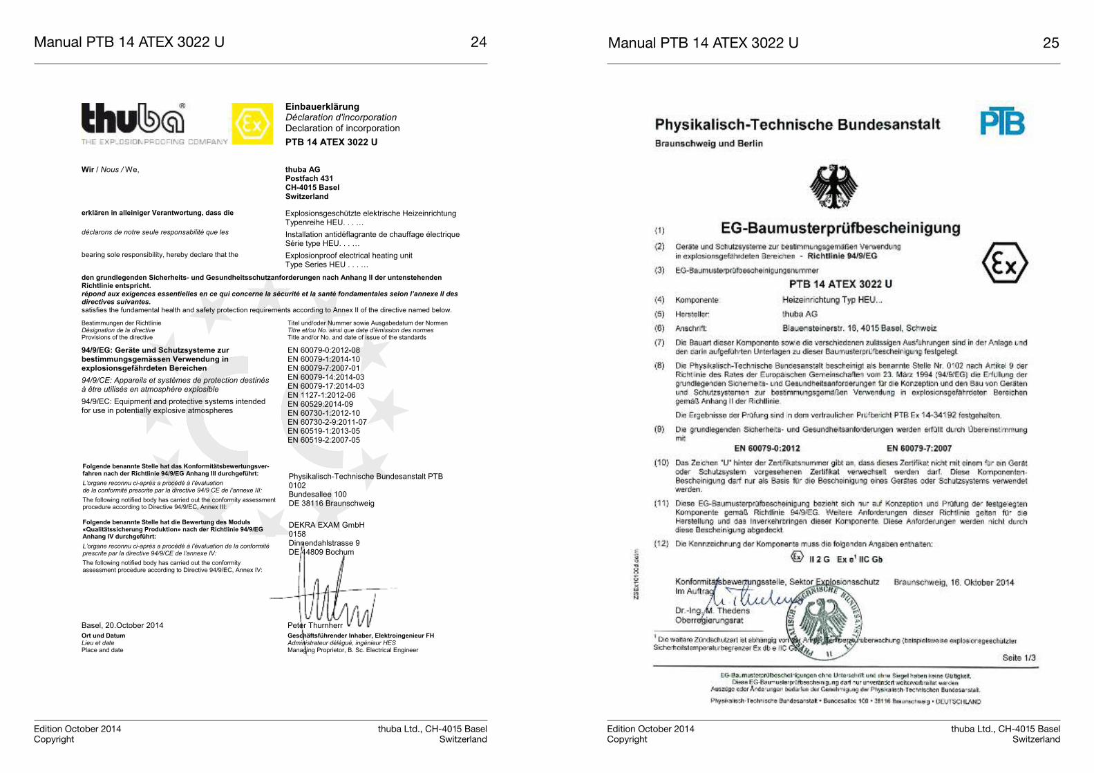
Einbauerklärung Déclaration d'incorporation Declaration of incorporation PTB 14 ATEX 3022 U
Wir / Nous / We,
thuba AG Postfach 431 CH-4015 Basel Switzerland
erklären in alleiniger Verantwortung, dass die déclarons de notre seule responsabilité que les bearing sole responsibility, hereby declare that the
Explosionsgeschützte elektrische Heizeinrichtung Typenreihe HEU. . . … Installation antidéflagrante de chauffage électrique Série type HEU. . . … Explosionproof electrical heating unit Type Series HEU . . . …
den grundlegenden Sicherheits- und Gesundheitsschutzanforderungen nach Anhang II der untenstehenden Richtlinie entspricht. répond aux exigences essentielles en ce qui concerne la sécurité et la santé fondamentales selon l’annexe II des directives suivantes. satisfies the fundamental health and safety protection requirements according to Annex II of the directive named below. Bestimmungen der Richtlinie Désignation de la directive Provisions of the directive
Titel und/oder Nummer sowie Ausgabedatum der Normen Titre et/ou No. ainsi que date d’émission des normes Title and/or No. and date of issue of the standards
94/9/EG: Geräte und Schutzsysteme zur bestimmungsgemässen Verwendung in explosionsgefährdeten Bereichen 94/9/CE: Appareils et systèmes de protection destinés à être utilisés en atmosphère explosible 94/9/EC: Equipment and protective systems intended for use in potentially explosive atmospheres
EN 60079-0:2012-08 EN 60079-1:2014-10 EN 60079-7:2007-01 EN 60079-14:2014-03 EN 60079-17:2014-03 EN 1127-1:2012-06 EN 60529:2014-09 EN 60730-1:2012-10 EN 60730-2-9:2011-07 EN 60519-1:2013-05 EN 60519-2:2007-05
Folgende benannte Stelle hat das Konformitätsbewertungsver-fahren nach der Richtlinie 94/9/EG Anhang III durchgeführt: L’organe reconnu ci-après a procédé à l’évaluation de la conformité prescrite par la directive 94/9 CE de l’annexe III: The following notified body has carried out the conformity assessment procedure according to Directive 94/9/EC, Annex III:
Physikalisch-Technische Bundesanstalt PTB 0102 Bundesallee 100 DE 38116 Braunschweig
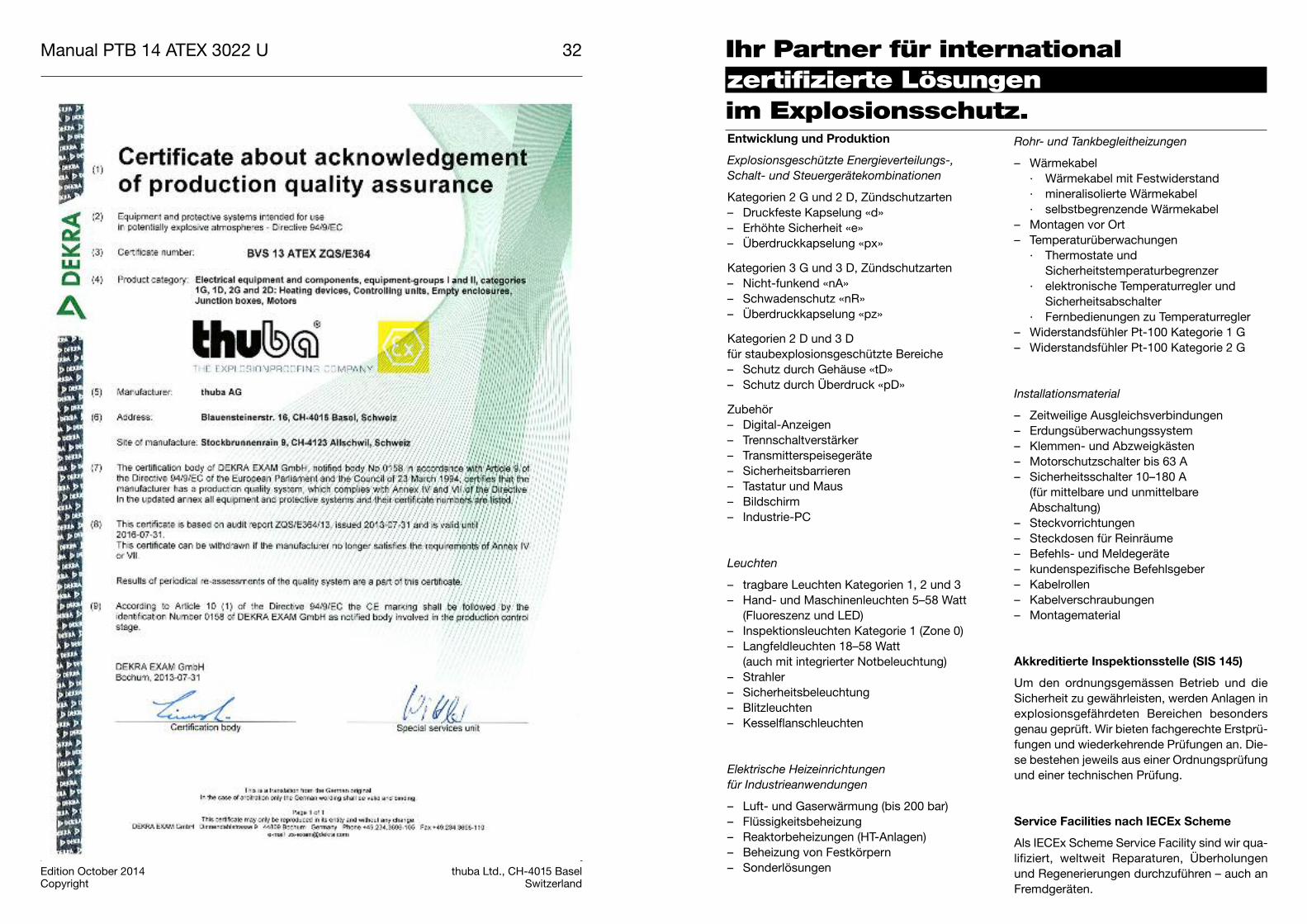
Folgende benannte Stelle hat die Bewertung des Moduls «Qualitätssicherung Produktion» nach der Richtlinie 94/9/EG Anhang IV durchgeführt: L’organe reconnu ci-après a procédé à l’évaluation de la conformité prescrite par la directive 94/9/CE de l’annexe IV: The following notified body has carried out the conformity assessment procedure according to Directive 94/9/EC, Annex IV:
DEKRA EXAM GmbH 0158 Dinnendahlstrasse 9 DE 44809 Bochum
Basel, 20.October 2014 Peter Thurnherr Ort und Datum Lieu et date Place and date
Geschäftsführender Inhaber, Elektroingenieur FH Administrateur délégué, ingénieur HES Managing Proprietor, B. Sc. Electrical Engineer
Manual PTB 14 ATEX 3022 U 24
Edition October 2014 thuba Ltd., CH-4015 BaselCopyright Switzerland
Manual PTB 14 ATEX 3022 U 27
Edition October 2014 thuba Ltd., CH-4015 BaselCopyright Switzerland
Manual PTB 14 ATEX 3022 U 26
Edition October 2014 thuba Ltd., CH-4015 BaselCopyright Switzerland
Manual PTB 14 ATEX 3022 U 29
Edition October 2014 thuba Ltd., CH-4015 BaselCopyright Switzerland
Manual PTB 14 ATEX 3022 U 28
Edition October 2014 thuba Ltd., CH-4015 BaselCopyright Switzerland
Manual PTB 14 ATEX 3022 U 31
Edition October 2014 thuba Ltd., CH-4015 BaselCopyright Switzerland
Manual PTB 14 ATEX 3022 U 30
Edition October 2014 thuba Ltd., CH-4015 BaselCopyright Switzerland
Manual PTB 14 ATEX 3022 U 32
Edition October 2014 thuba Ltd., CH-4015 BaselCopyright Switzerland
Ihr Partner für internationalzertifizierte Lösungenim Explosionsschutz.Entwicklung und Produktion
Explosionsgeschützte Energieverteilungs-,Schalt- und Steuergerätekombinationen
Kategorien 2 G und 2 D, Zündschutzarten– Druckfeste Kapselung «d»– Erhöhte Sicherheit «e»– Überdruckkapselung «px»
Kategorien 3 G und 3 D, Zündschutzarten– Nicht-funkend «nA» – Schwadenschutz «nR» – Überdruckkapselung «pz»
Kategorien 2 D und 3 Dfür staubexplosionsgeschützte Bereiche– Schutz durch Gehäuse «tD» – Schutz durch Überdruck «pD»
Zubehör – Digital-Anzeigen– Trennschaltverstärker– Transmitterspeisegeräte– Sicherheitsbarrieren– Tastatur und Maus– Bildschirm– Industrie-PC
Leuchten
– tragbare Leuchten Kategorien 1, 2 und 3– Hand- und Maschinenleuchten 5–58 Watt(Fluoreszenz und LED)
– Inspektionsleuchten Kategorie 1 (Zone 0)– Langfeldleuchten 18–58 Watt (auch mit integrierter Notbeleuchtung)
– Strahler– Sicherheitsbeleuchtung – Blitzleuchten– Kesselflanschleuchten
Elektrische Heizeinrichtungen für Industrieanwendungen
– Luft- und Gaserwärmung (bis 200 bar)– Flüssigkeitsbeheizung– Reaktorbeheizungen (HT-Anlagen)– Beheizung von Festkörpern– Sonderlösungen
Rohr- und Tankbegleitheizungen
– Wärmekabel· Wärmekabel mit Festwiderstand· mineralisolierte Wärmekabel· selbstbegrenzende Wärmekabel
– Montagen vor Ort– Temperaturüberwachungen· Thermostate und Sicherheitstemperaturbegrenzer
· elektronische Temperaturregler undSicherheitsabschalter
· Fernbedienungen zu Temperaturregler– Widerstandsfühler Pt-100 Kategorie 1 G– Widerstandsfühler Pt-100 Kategorie 2 G
Installationsmaterial
– Zeitweilige Ausgleichsverbindungen– Erdungsüberwachungssystem– Klemmen- und Abzweigkästen– Motorschutzschalter bis 63 A– Sicherheitsschalter 10–180 A(für mittelbare und unmittelbareAbschaltung)
– Steckvorrichtungen– Steckdosen für Reinräume– Befehls- und Meldegeräte– kundenspezifische Befehlsgeber– Kabelrollen– Kabelverschraubungen– Montagematerial
Akkreditierte Inspektionsstelle (SIS 145)
Um den ordnungsgemässen Betrieb und dieSicherheit zu gewährleisten, werden Anlagen inexplosionsgefährdeten Bereichen besondersgenau geprüft. Wir bieten fachgerechte Erstprü-fungen und wiederkehrende Prüfungen an. Die-se bestehen jeweils aus einer Ordnungsprüfungund einer technischen Prüfung.
Service Facilities nach IECEx Scheme
Als IECEx Scheme Service Facility sind wir qua-lifiziert, weltweit Reparaturen, Überholungenund Regenerierungen durchzuführen – auch anFremdgeräten.
Your partner for internationallycertified solutionsin explosion protection
Votre partenaire pour lessolutions certifiéesen protection antidéflagrante
Pipe and tank trace heating systems
– heating cables· heating cables with fixed resistors · mineral-insulated heating cables· self-limiting heating cables
– site installation – temperature monitoring systems· thermostats and safety temperature limiters
· electronic temperature controllers and safety cutouts
· remote controls for temperature controller
– resistance temperature detectors Pt-100 Category 1 G
– resistance temperature detectors Pt-100 Category 2 G
Installation material
– temporary bonding– earth monitoring system– terminals and junction boxes – motor protecting switches up to 63 A– safety switches 10 to 180 A(for indirect and direct tripping)
– plug-and-socket devices– socket outlets for clean rooms – control and indicating devices– customized control stations– cable reels– cable glands– fastening material
Accredited inspection body (SIS 145)
Extremely strict inspections are carried out toguarantee the correct operation and safety ofinstallations in hazardous areas. We carry outboth professional initial inspections and period-ic inspections. These consist of a documenta-tion and organisation check and a technicalinspection.
Service Facilities according to IECEx Scheme
As an IECEx Scheme service facility we are qua-lified to carry out repairs, overhauling and rege-neration work all over the world – even on equip-ment from other manufacturers.
Design and Production
Explosionproof multipurpose distribution, switching and control units
Categories 2 G and 3 D, protection types– flameproof enclosure «d»– increased safety «e»– pressurized enclosure «px»
Categories 3 G and 3 D, protection types– non-sparking «nA»– restricted breathing enclosure «nR»– pressurized enclosure «pz»
Categories 2 D and 3 Dfor areas at risk of dust explosions– protection by enclosure «tD»– type of protection «pD»
Accessories– digital displays– disconnect amplifiers– transmitter power packs– safety barriers– keyboard and mouse– monitor– industrial PC
Lamps
– portable lamps, Categories 1, 2 and 3– hand-held and machine lamps 5 to 58 W(fluorescent and LED)
– inspection lamps Category 1 (Zone 0)– fluorescent light fixtures 18 to 58 W (also with integrated emergency lighting)
– reflector lamps– safety lighting – flashing lamps– boiler flange lamps
Electric heaters for industrial applications
– heating of air and gases (up to 200 bar)– heating of liquids– reactor heating systems (HT installations)– heating of solids – special solutions
Chauffages de conduites et de citernes
– câbles thermoconducteurs· câbles chauffants à résistance fixe· câbles chauffants à isolation minérale · câbles chauffants autolimités
– montage sur site– contrôle de température· thermostats et limiteurs de température de sécurité
· thermorégulateurs électroniques etrupteurs de sécurité
· télécommandes de thermorégulateur– capteurs à résistance Pt-100 catégorie 1 G– capteurs à résistance Pt-100 catégorie 2 G
Matériel de montage et d’installation
– Liason temporaire– Dispositif de contrôle de la mise à la terre– boîtes à bornes et de jonction– disjoncteurs-protecteurs jusqu’à 63 A– interrupteurs de sécurité 10 à 180 A(pour coupure directe ou indirecte)
– connecteurs– prises de courant pour salles propres– appareils de commande– postes de commande selon spécificationsclient
– dévidoirs de câble– presse-étoupe– matériel de montage
Organe d’inspection accrédité (SIS 145)
Dans le but d’assurer une exploitation correcteet la sécurité, les installations en atmosphèreexplosive doivent être inspectées de manièreparticulièrement approfondie. Nous proposonségalement, en plus d’un premier examen, desinspections de routine et des vérifications pério-diques in situ.
Service clients selon le modèle IECEx
Par notre service clients certifié selon le modè-le IECEx nous sommes qualifiés pour procéderdans le monde entier aux réparations, révisionset remises en état des équipements – mêmeceux d’autres fabricants.
Conception et production
Dispositifs antidéflagrants de distributiond’éner gie, de couplage et de commande
Catégories 2 G et 2 D, modes de protection– enveloppe antidéflagrante «d»– sécurité augmentée «e»– enveloppe en surpression «px»
Catégories 3 G et 3 D, modes de protection– anti-étincelles «nA» – respiration limitée «nR»– surpression interne «pz»
Catégories 2 D et 3 Dpour zones protégées contre les explosions depoussière– Protection par enveloppes «tD»– Protection par surpression «pD»
Accessoires– affichage (visuel) numérique – amplificateurs de sectionneurs– appareils d’alimentation d’émetteurs– barrières de sécurité– clavier et souris– écran– PC industriel (ordinateur industriel)
Luminaires
– baladeuses catégories 1, 2 et 3– luminaires pour machines et baladeuses 5 à 58 watts (fluorescents et DEL)
– luminaires d’inspection catégorie 1 (zone 0)– luminaires longitudinaux 18 à 58 watts (aussi avec éclairage de secours intégré)
– projecteurs – éclairage de secours – lampes éclair– luminaires à bride pour chaudières
Chauffages électriques pour applications industrielles
– chauffages de l’air et de gaz (jusqu’à 200bars)
– chauffages de liquides– chauffages à réacteur (thermostables)– chauffages de corps solides– solutions spécifiques

thuba Ltd.CH-4015 Basel
Phone +41 61 307 80 00 Fax +41 61 307 80 10E-mail [email protected] www.thuba.com