
ExtractingandUsingPowerChannelDatafor ... · ExtractingandUsingPowerChannelDatafor...
52
Bachelor Thesis Alexander Dmitriev Extracting and Using Power Channel Data for Automaton Inference Using Sparse Alphabets June 27, 2016 supervised by: S. Schupp A. Wichmann Hamburg University of Technology (TUHH) Technische Universität Hamburg-Harburg Institute for Software Systems 21073 Hamburg
Transcript of ExtractingandUsingPowerChannelDatafor ... · ExtractingandUsingPowerChannelDatafor...

Bachelor Thesis
Alexander Dmitriev
Extracting and Using Power Channel Data forAutomaton Inference Using Sparse Alphabets
June 27, 2016
supervised by:S. SchuppA. Wichmann
Hamburg University of Technology (TUHH)Technische Universität Hamburg-HarburgInstitute for Software Systems21073 Hamburg


Eidesstattliche Erklärung
Ich versichere an Eides statt, dass ich die vorliegende Bachelorarbeit selbstständig ver-fasst und keine anderen als die angegebenen Quellen und Hilfsmittel verwendet habe. DieArbeit wurde in dieser oder ähnlicher Form noch keiner Prüfungskommission vorgelegt.
Hamburg, den 27. Juni 2016 Alexander Dmitriev
iii

Contents
Contents
1 Introduction 1
2 Background and Related Work 32.1 Digital Integrated Circuits . . . . . . . . . . . . . . . . . . . . . . . . . . . 3
2.1.1 Reverse Engineering Integrated Circuits . . . . . . . . . . . . . . . 42.2 Angluin L* Learning . . . . . . . . . . . . . . . . . . . . . . . . . . . . . . 6
2.2.1 Algorithm . . . . . . . . . . . . . . . . . . . . . . . . . . . . . . . . 72.2.2 Example Run . . . . . . . . . . . . . . . . . . . . . . . . . . . . . . 72.2.3 Membership Queries and Equivalence Tests . . . . . . . . . . . . . 9
2.3 Power Analysis . . . . . . . . . . . . . . . . . . . . . . . . . . . . . . . . . 102.3.1 Security Attacks . . . . . . . . . . . . . . . . . . . . . . . . . . . . 102.3.2 State Representation . . . . . . . . . . . . . . . . . . . . . . . . . . 11
2.4 Trace Classification . . . . . . . . . . . . . . . . . . . . . . . . . . . . . . . 11
3 A Sparse Alphabet and Power Channel Analysis 153.1 Toggle Alphabet . . . . . . . . . . . . . . . . . . . . . . . . . . . . . . . . 15
3.1.1 Viewing Input Pins as Output Pins . . . . . . . . . . . . . . . . . . 163.2 Power Channel Measurement . . . . . . . . . . . . . . . . . . . . . . . . . 17
3.2.1 Classifiers . . . . . . . . . . . . . . . . . . . . . . . . . . . . . . . . 183.2.2 Reducing the Impact of Noise . . . . . . . . . . . . . . . . . . . . . 19
3.3 Implementation of Alice2 . . . . . . . . . . . . . . . . . . . . . . . . . . . 19
4 Experiments 234.1 Experiment Goals . . . . . . . . . . . . . . . . . . . . . . . . . . . . . . . 234.2 Experiment Setup . . . . . . . . . . . . . . . . . . . . . . . . . . . . . . . 23
4.2.1 Devices and Actors . . . . . . . . . . . . . . . . . . . . . . . . . . . 234.2.2 Physical Effects . . . . . . . . . . . . . . . . . . . . . . . . . . . . . 24
4.3 Raw Results . . . . . . . . . . . . . . . . . . . . . . . . . . . . . . . . . . . 274.3.1 State of the Art: Alice . . . . . . . . . . . . . . . . . . . . . . . . . 274.3.2 Alice2 . . . . . . . . . . . . . . . . . . . . . . . . . . . . . . . . . . 29
4.4 Case Analyses and Interpretations . . . . . . . . . . . . . . . . . . . . . . 334.5 Answers to the Research Questions . . . . . . . . . . . . . . . . . . . . . . 404.6 Future Work . . . . . . . . . . . . . . . . . . . . . . . . . . . . . . . . . . 41
5 Conclusion 43
v


1 Introduction
Automaton inference algorithms like L* explore the state space of a system by askingit to process sequences of input words. Although exploring the state space is relativelycheap, verifying the equivalence of the system and the model is not. Due to the largeinput alphabet size the number of input sequences to an automaton grows exponentiallywith the input alphabet size. Here we show that a logical abstraction of the inputalphabet, based on the toggling of single pins, in combination with power side channelanalysis can be used instead of the normal alphabet. Based on how the power channeldata is processed, different non-functional behavior, which is not visible from the logicaloutput, can be extracted from the system. The main drawback of this method is thatmeasuring the power consumption slows the process down to a fraction of its originalspeed. In general this research demonstrates that our approach using a sparse alphabetdecreases the number of queries to the actual system that is required for the inferenceof the system. Using power channel classifications mostly leads to extensions of theautomata learned with a sparse alphabet, involving complex behavioral patterns. Withbetter equipment and more advanced power measurement classification algorithms thespeed and stability of this approach can be increased.Specifically this work focuses on the implementation and evaluation of the toggle
alphabet and a simple power channel analysis applied to simple integrated circuits (IC).As a starting point for the implementation the learning tool Alice by Tanya Braun waschosen [3]. It features a test bench for learning various kinds of ICs using the libalf1library which includes an implementation of the automaton inference algorithm L* byDana Angluin. So far the test bench operated with full input words, which may changethe values of all input pins at each input word. The toggle alphabet aims at decreasingthe alphabet size by restricting the input words to toggling only one pin at a time. Thegoal of the power analysis is to improve the performance of the toggle alphabet by givingit hints how the system being tested reacted to a new input. To make these hints usablein the existing test bench, classification is needed. Several classifiers are presented andcompared.
Research Questions
RQ1 How can plain L* automaton learning be improved by using sparse al-phabets? The purpose of the toggle alphabet is the reduction of the alphabet size,and instead expanding the resulting state space. This research question targets acomparison between learning the behavior of an IC with a full alphabet and thetoggle alphabet in terms of correctness and runtime, measured by the number ofqueries used for learning.
RQ2 To what extent does the power channel contain information about theIC state? To employ meaningful power channel analysis on ICs the power channelmust contain some information which can be extracted and classified.
1http://libalf.informatik.rwth-aachen.de
1
1 Introduction
RQ3 To what extent is it possible to classify power traces to differentiate ICstates? We are interested in what kind of behavior can be extracted from thepower channel.
RQ4 How can power channel analysis in combination with using a sparsealphabet be used to improve the L* automaton learning algorithm?This research question focuses on comparing the results of learning ICs using thetoggle alphabet with and without power channel analysis and determine to whatextent the former outperforms the latter.
The first section of this work is dedicated to explaining the prerequisites for the newmethods. That includes the following four main topics: the structure and abilities ofICs of which a representative test suite is chosen; an explanation of how L* works, anda step-by-step walk-through of an example system being learned; what other outputs ahardware system has and especially how the power channel can be used to gain moreinformation than the device actually presents; and a short introduction to machinelearning, which is required to be able to handle the power channel measurements.In the following section we describe the toggle alphabet and the power channel analysis,as well as their integration into the existing application. Hereafter we describe theclassifiers used later in the experiments and introduce the configuration parameters of thepower channel analysis. This part concludes with a specification of the implementationand a listing of noteworthy details of the former.Section 4 describes the experimental part of this work. It consists of the experimentgoals, which are derived from the research questions, the setup, describing the experimenthardware and environment, and the actual results. As part of the results, pitfalls andshortcomings of the used setup are listed.Further, the result section contains a description of the raw values obtained throughthe experiments and an analysis part, which explains the specific behavior of both thechips and the test bench. Finally, the conclusion sums up why and when this method isbeneficial to automaton inference and contains suggestions for future work.
2
2 Background and Related Work
In this chapter we describe the prerequisites required for understanding the discussedtopics. These topics include digital ICs, which are used as test subjects in our framework,the automaton inference algorithm L*, on which the framework is built, an overview ofpower side channel analysis and a brief introduction to machine learning.
2.1 Digital Integrated Circuits
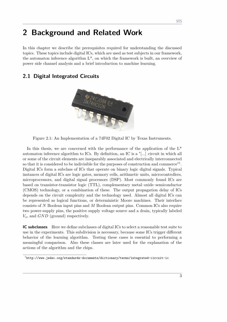
Figure 2.1: An Implementation of a 74F02 Digital IC by Texas Instruments.
In this thesis, we are concerned with the performance of the application of the L*automaton inference algorithm to ICs. By definition, an IC is a "[...] circuit in which allor some of the circuit elements are inseparably associated and electrically interconnectedso that it is considered to be indivisible for the purposes of construction and commerce"1.Digital ICs form a subclass of ICs that operate on binary logic digital signals. Typicalinstances of digital ICs are logic gates, memory cells, arithmetic units, microcontrollers,microprocessors, and digital signal processors (DSP). Most commonly found ICs arebased on transistor-transistor logic (TTL), complementary metal–oxide–semiconductor(CMOS) technology, or a combination of these. The output propagation delay of ICsdepends on the circuit complexity and the technology used. Almost all digital ICs canbe represented as logical functions, or deterministic Moore machines. Their interfaceconsists of N Boolean input pins andM Boolean output pins. Common ICs also requiretwo power-supply pins, the positive supply voltage source and a drain, typically labeledVcc and GND (ground) respectively.
IC subclasses Here we define subclasses of digital ICs to select a reasonable test suite touse in the experiments. This subdivision is necessary, because some ICs trigger differentbehavior of the learning algorithm. Testing these cases is essential to performing ameaningful comparison. Also these classes are later used for the explanation of theactions of the algorithm and the chips.
1http://www.jedec.org/standards-documents/dictionary/terms/integrated-circuit-ic
3

2 Background and Related Work
Stateless/pure: ICs are called stateless when their output is fully determined by thecurrent input word. Stateless chips do not contain any kind of flip-flops.
Stateful: Stateful ICs, in contrast to stateless chips, contain flip-flops. The output isnot anymore determined solely by the current input word, but by the initial stateand the applied input sequence.
Synchronous: Synchronous ICs contain a clock pin. The clock pin is used to perform astate transition. It is usually implemented such that at rising edges of the clocksignal the input pins are read and the internal state is recomputed.
Asynchronous: In contrast to synchronous ICs, asynchronous ICs do not contain a clockpin. Asynchronous ICs either rely on the simultaneous toggling of the input pinsor on the order of toggling to perform a specific action. Many chips have anasynchronous negative-enable reset pin, which, when activated, bypasses the clockpin in synchronous chips and returns the chip to a well-defined start state.
Bidirectional: ICs that can switch the direction of a pin are called bidirectional. Al-though bidirectionality increases the complexity of the chip compared to regularunidirectional chips, the handling of bidirectional pins does not pose a problem.The pins of a bidirectional chip can be viewed as input and output simultaneously.
Another type of digital ICs are programmable array logic (PAL) and gate array logic(GAL) chips, which are configurable for a specific purpose. PAL chips allow for theselection of multiple groups of inputs and negated inputs, which are passed through ANDgates. The outputs of the AND gates are then passed on through an OR gate, resultingin a fixed sum of programmable products function. This configurability empowers PALchips to represent a wide selection of logic functions. GALs are similar to PAL chips,but are erasable and re-programmable. Upon manufacturing the chips have undefinedbehavior, and are only labeled with the chip type.
2.1.1 Reverse Engineering Integrated CircuitsFor the development of medium to large scale systems involving ICs, documentation isa crucial component. PALs and GALs in particular are subjects to a stronger wear andtear than hardwired ICs. We cannot assume that for each IC, especially for custom-configured PALs and GALs, the corresponding documentation is available, so that theycan, if necessary, be replicated. When documentation is not available or when thechip labels are erased, reconstructing a chip’s functionality becomes a hardware analysisproblem or a learning problem. Modern state-of-the-art intrusive chip inspection devicescan be used to directly view the wiring on the chip. With no access to such devicesone can resort to non-intrusive reverse engineering. Some approaches, referring to thework of Tanya Braun [3], can currently learn chips with low complexity, such as logicgates, memory cells and arithmetic units. The learning framework, Alice, presented byTanya Braun, is primarily concerned with different equivalence strategies to conquer theunknown behavior of a chip. This problem is explained in more detail in Section 2.2.3.
4
2.1 Digital Integrated Circuits
A major problem of Alice’s learning strategy altogether is the large input alphabet size.With this research we hope to induce methods which reduce the effort required for ICinference - on the one hand reducing the alphabet size by using the toggle alphabet,and on the other hand increasing the information gain per query through power channelclassification. To test the performance of our extensions of the algorithm we selected arepresentative test suite of ICs.
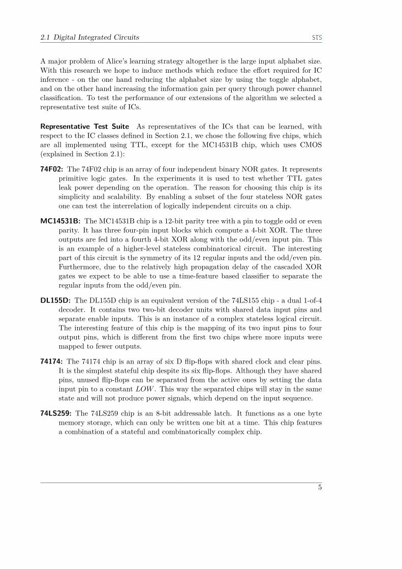
Representative Test Suite As representatives of the ICs that can be learned, withrespect to the IC classes defined in Section 2.1, we chose the following five chips, whichare all implemented using TTL, except for the MC14531B chip, which uses CMOS(explained in Section 2.1):
74F02: The 74F02 chip is an array of four independent binary NOR gates. It representsprimitive logic gates. In the experiments it is used to test whether TTL gatesleak power depending on the operation. The reason for choosing this chip is itssimplicity and scalability. By enabling a subset of the four stateless NOR gatesone can test the interrelation of logically independent circuits on a chip.
MC14531B: The MC14531B chip is a 12-bit parity tree with a pin to toggle odd or evenparity. It has three four-pin input blocks which compute a 4-bit XOR. The threeoutputs are fed into a fourth 4-bit XOR along with the odd/even input pin. Thisis an example of a higher-level stateless combinatorical circuit. The interestingpart of this circuit is the symmetry of its 12 regular inputs and the odd/even pin.Furthermore, due to the relatively high propagation delay of the cascaded XORgates we expect to be able to use a time-feature based classifier to separate theregular inputs from the odd/even pin.
DL155D: The DL155D chip is an equivalent version of the 74LS155 chip - a dual 1-of-4decoder. It contains two two-bit decoder units with shared data input pins andseparate enable inputs. This is an instance of a complex stateless logical circuit.The interesting feature of this chip is the mapping of its two input pins to fouroutput pins, which is different from the first two chips where more inputs weremapped to fewer outputs.
74174: The 74174 chip is an array of six D flip-flops with shared clock and clear pins.It is the simplest stateful chip despite its six flip-flops. Although they have sharedpins, unused flip-flops can be separated from the active ones by setting the datainput pin to a constant LOW . This way the separated chips will stay in the samestate and will not produce power signals, which depend on the input sequence.
74LS259: The 74LS259 chip is an 8-bit addressable latch. It functions as a one bytememory storage, which can only be written one bit at a time. This chip featuresa combination of a stateful and combinatorically complex chip.
5

2 Background and Related Work
2.2 Angluin L* LearningThe L* automaton inference algorithm is the core of the learning test bench. It waspublished by Dana Angluin in 1987 in the paper "Learning Regular Sets from Queriesand Counterexamples" [1]. As the name implies, it is used to learn regular sets by posingmembership queries and handling counterexamples.
The language of an automaton is defined to be a sequence of words, where words arethe labels of the transitions between states. The set of all words is called the alphabet Σ.The algorithm contains two roles, a teacher and a learner. The learner asks questions,which the teacher answers truthfully, until he reaches a conjecture. A conjecture is acomplete automaton. Such queries are called membership queries. They are generatedby taking the input sequence that leads to a known state and appending every input wordonce. This is repeated for all known states. In this phase the states are distinguished bytheir output. This way, when two states reached by different input sequences producethe same output for every input word, they are assumed to be the same state. This phaseis used to explore the state space of the automaton. When there are no more questionsto ask, the learner asks an equivalence query. The teacher then has to determine whetherthe model constructed by the learner is equivalent to the actual system. The teacher issupposed to be omniscient, and thus able to check the equivalence of a model and theactual system. On equivalence the algorithm terminates. When the model differs fromthe system, the teacher has to provide a counterexample, which is a sequence of inputs,for which the system produces a different output than the model has predicted. Thelearner adds the counterexample to his knowledge base and starts asking membershipqueries again.Internally the learner maintains a knowledge base of all currently asked membership
queries. The knowledge base is a table in which every row corresponds to a state.The row labels are input sequences leading to a state, and the column labels are inputsequences. The table entries are output words retrieved by asking membership queries,which are generated by appending the column labels to the end of the row labels. Thetable is split into two parts, upper and lower. The upper part contains actual states.The lower part contains the successor states of those from the upper part. λ denotes theempty sequence.The knowledge base has two important properties: closedness and consistence. Closed-
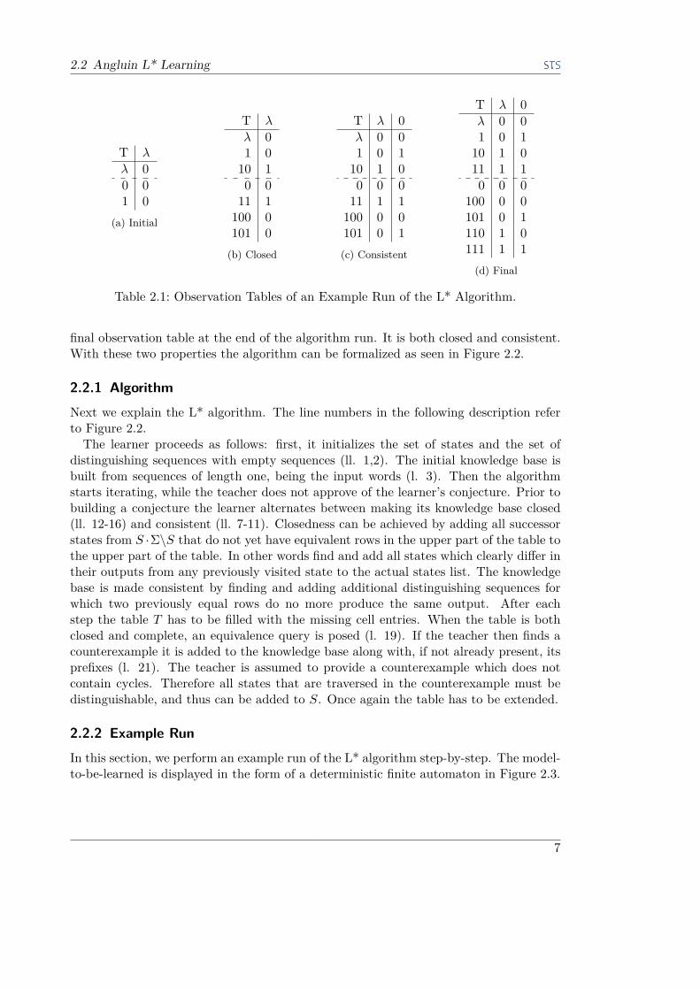
ness means that each successor row has at least one row from the upper part with identi-cal cell entries. Speaking in terms of the algorithm this means that no state in the lowerpart is distinguishable from an actual state in the upper part. Consistency means thatevery two rows in the upper part must produce different outputs for some suffix, whichcan be inserted as a column. In Table 2.1 you can see observation tables at differentstages of the L* algorithm. These tables will be later used in the explanation of theexample run of the algorithm, which is Section 2.2.2. In Table 2.1a there is the initialobservation table. In this particular case it is both closed and consistent. In Table 2.1byou see a closed, but not consistent table. In the upper part there are two rows withthe same cell entries. Table 2.1c depicts a consistent, but not closed observation table.The lower part contains a row with unique cell entries. The table in Table 2.1d is the
6
2.2 Angluin L* Learning
T λ
λ 00 01 0
(a) Initial
T λ
λ 01 010 10 011 1
100 0101 0
(b) Closed
T λ 0λ 0 01 0 110 1 00 0 011 1 1
100 0 0101 0 1(c) Consistent
T λ 0λ 0 01 0 110 1 011 1 10 0 0
100 0 0101 0 1110 1 0111 1 1
(d) Final
Table 2.1: Observation Tables of an Example Run of the L* Algorithm.
final observation table at the end of the algorithm run. It is both closed and consistent.With these two properties the algorithm can be formalized as seen in Figure 2.2.
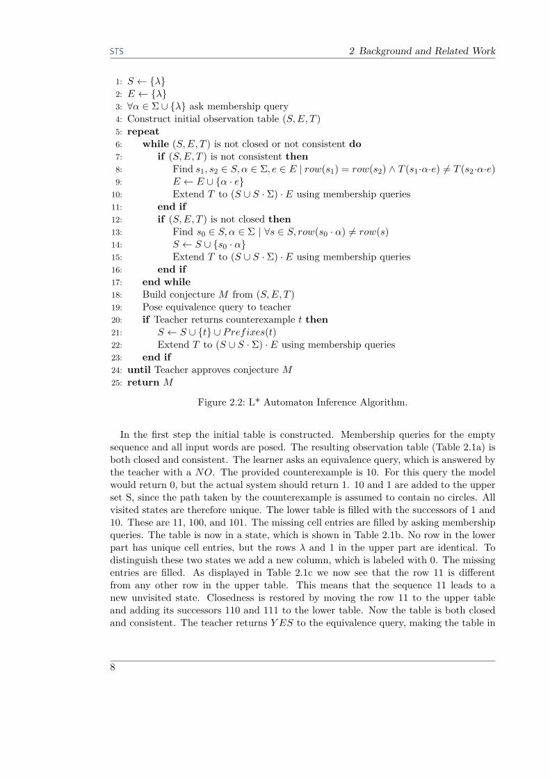
2.2.1 AlgorithmNext we explain the L* algorithm. The line numbers in the following description referto Figure 2.2.The learner proceeds as follows: first, it initializes the set of states and the set of
distinguishing sequences with empty sequences (ll. 1,2). The initial knowledge base isbuilt from sequences of length one, being the input words (l. 3). Then the algorithmstarts iterating, while the teacher does not approve of the learner’s conjecture. Prior tobuilding a conjecture the learner alternates between making its knowledge base closed(ll. 12-16) and consistent (ll. 7-11). Closedness can be achieved by adding all successorstates from S ·Σ\S that do not yet have equivalent rows in the upper part of the table tothe upper part of the table. In other words find and add all states which clearly differ intheir outputs from any previously visited state to the actual states list. The knowledgebase is made consistent by finding and adding additional distinguishing sequences forwhich two previously equal rows do no more produce the same output. After eachstep the table T has to be filled with the missing cell entries. When the table is bothclosed and complete, an equivalence query is posed (l. 19). If the teacher then finds acounterexample it is added to the knowledge base along with, if not already present, itsprefixes (l. 21). The teacher is assumed to provide a counterexample which does notcontain cycles. Therefore all states that are traversed in the counterexample must bedistinguishable, and thus can be added to S. Once again the table has to be extended.
2.2.2 Example RunIn this section, we perform an example run of the L* algorithm step-by-step. The model-to-be-learned is displayed in the form of a deterministic finite automaton in Figure 2.3.
7
2 Background and Related Work
1: S ← {λ}2: E ← {λ}3: ∀α ∈ Σ ∪ {λ} ask membership query4: Construct initial observation table (S,E, T )5: repeat6: while (S,E, T ) is not closed or not consistent do7: if (S,E, T ) is not consistent then8: Find s1, s2 ∈ S, α ∈ Σ, e ∈ E | row(s1) = row(s2) ∧ T (s1·α·e) 6= T (s2·α·e)9: E ← E ∪ {α · e}
10: Extend T to (S ∪ S · Σ) · E using membership queries11: end if12: if (S,E, T ) is not closed then13: Find s0 ∈ S, α ∈ Σ | ∀s ∈ S, row(s0 · α) 6= row(s)14: S ← S ∪ {s0 · α}15: Extend T to (S ∪ S · Σ) · E using membership queries16: end if17: end while18: Build conjecture M from (S,E, T )19: Pose equivalence query to teacher20: if Teacher returns counterexample t then21: S ← S ∪ {t} ∪ Prefixes(t)22: Extend T to (S ∪ S · Σ) · E using membership queries23: end if24: until Teacher approves conjecture M25: return M
Figure 2.2: L* Automaton Inference Algorithm.
In the first step the initial table is constructed. Membership queries for the emptysequence and all input words are posed. The resulting observation table (Table 2.1a) isboth closed and consistent. The learner asks an equivalence query, which is answered bythe teacher with a NO. The provided counterexample is 10. For this query the modelwould return 0, but the actual system should return 1. 10 and 1 are added to the upperset S, since the path taken by the counterexample is assumed to contain no circles. Allvisited states are therefore unique. The lower table is filled with the successors of 1 and10. These are 11, 100, and 101. The missing cell entries are filled by asking membershipqueries. The table is now in a state, which is shown in Table 2.1b. No row in the lowerpart has unique cell entries, but the rows λ and 1 in the upper part are identical. Todistinguish these two states we add a new column, which is labeled with 0. The missingentries are filled. As displayed in Table 2.1c we now see that the row 11 is differentfrom any other row in the upper table. This means that the sequence 11 leads to anew unvisited state. Closedness is restored by moving the row 11 to the upper tableand adding its successors 110 and 111 to the lower table. Now the table is both closedand consistent. The teacher returns Y ES to the equivalence query, making the table in
8

2.2 Angluin L* Learning
Figure 2.3: Example Automaton.
Table 2.1d final.
2.2.3 Membership Queries and Equivalence TestsMembership Queries Membership queries are sequences of input words. A member-ship query is asked by sequentially applying each input word to the system. Prior tothat the system must be brought to a start state. This is usually done by sending a resetword, which in ICs is often defined as all-zero. If the device under test does not reactproperly to this type of clear, then a logical approach can be used. Homing sequences,as introduced by Rivest and Shapire [16], solve this problem by creating a new learnerfor each new state seen. After a learner asks a membership query, another learner ischosen, based on the state that the system has reached. This way there is no uniquereset state needed. Instead, each learner has its own starting state. As soon as one ofthose learners reaches a valid conjecture, the algorithm terminates. This method hasbeen successfully used in Tanya Braun’s master thesis project. For the sake of simplicitywe chose a simpler approach in our work by only using ICs that can be cleared by an all-zero input word. The homing sequence approach is also applicable to our modificationof the algorithm.
Equivalence Tests To check the equivalence of the behavior of a black box with amodel representation given in the form of a deterministic finite automaton one wouldhave to check every possible input sequence. The input sequences can be represented inthe form of a tree.
9

2 Background and Related Work
Equivalence queries pose a problem in that they are not sound. Any valid model will beaccepted by the teacher, but also negative ones, which include incorrect behavior whichis not tested. The reason why this problem exists is the indistinguishability of similarlylooking states and the Halting problem. A simple example explaining the problem can bea system, which has one input pin and one output pin. Internally it contains a counter.Assume, for each rising edge of the input signal the counter is increased by one. The chipoutputs zero unless the counter value is 100. The internal state can not be seen fromthe outside, so after some membership queries the learner would come to the conclusionthat the chip always outputs zero.The teacher, when presented with a conjecture, does not know the actual model, so he
can only query the system and compare the outputs to the conjecture. It is impossible toverify the whole search tree, because it if infinite, and each additional layer exponentiallyincreases the number of queries. This topic has also been researched by Tanya Braun.She came to the conclusion that using search tree coverage strategies based on the chipclass provides a reasonable degree of equivalence.In the given example though, the real behavior can not be learned with purely logical
methods.
2.3 Power AnalysisPower channel analysis (PCA) is a method for system analysis. It is a side channelanalysis focusing on the power consumption (PC) of electrical devices. The key conceptof PCA is that different operations produce visibly different power measurements. Powertraces are split into two categories: static and dynamic. This categorization is performedrelative to the system analyzed. The static PC can be thought of as the power consumedby the system in-between operations. On the other hand, the dynamic PC is the changein PC on different operations relative to the static PC. In terms of a digital IC and ananalysis focusing on state transitions the static PC denotes the PC before and after a pinis toggled, while the dynamic PC is the fluctuation seen shortly after a pin is toggled. Thedynamic PC also contains artifacts produced by hazards in the logic circuits. Hazardsare transient incorrect outputs of the system that occur due to internal propagationdelay of internal circuitry.
2.3.1 Security AttacksPCA can be used to breach the security of electrical systems. Using measurements of thesystem which is processing particular commands, one can extract crucial information.There are different kinds of power side channel attacks. To name only a few, there issimple power analysis (SPA) and differential power analysis (DPA) [9]. With SPA, theattacker tries to infer the state of a system by analyzing and comparing power tracesmeasured when operating the device. Sophisticated encryption chips can not be learnedby SPA. With cryptosystems, SPA over a full encryption cycle can give hints about thecipher being used. In such attacks often the internal structure of the encryption systemis known, which significantly decreases the complexity. Here DPA can be applied. The
10
2.4 Trace Classification
encryption system is fed various inputs, while the ciphertext as well as the leaked power ismonitored. When a reasonable amount of power traces is gathered, they are aligned andanalyzed based on the proceedings of the used encryption algorithm. Modern securityrelevant system component manufacturers aim to reduce or obfuscate the power channeloutput information so that side channel attacks are no longer possible. The chips usedin our experiments are by themselves not security relevant.
2.3.2 State RepresentationAs an example of a successful SPA we summarize the results of Abdulah Abdulah Zadehand Howard M. Heys in [20]. Their research gives us an insight into how state informationcan be extracted from IC power traces. An SPA has been used to perform a side channelattack on a linear/non-linear feedback shift register (FSR). An FSR implements analgorithm, which, given an initial seed of length N , generates a sequence of keys thatcan be used for encryption. The next key is generated by computing f(r). f : {0, 1}N →{0,1} is called a feedback function, r : {0, 1}N is the current internal register value.After computing f(r) the register is shifted by one to the left and f(r) is inserted atthe rightmost position. Thus, by guessing the register value, which contains the currentencryption key, all subsequent keys can be computed, given that f is known. Thisalgorithm can be implemented as an IC.One particular property of an FSR is that the difference between the Hamming dis-
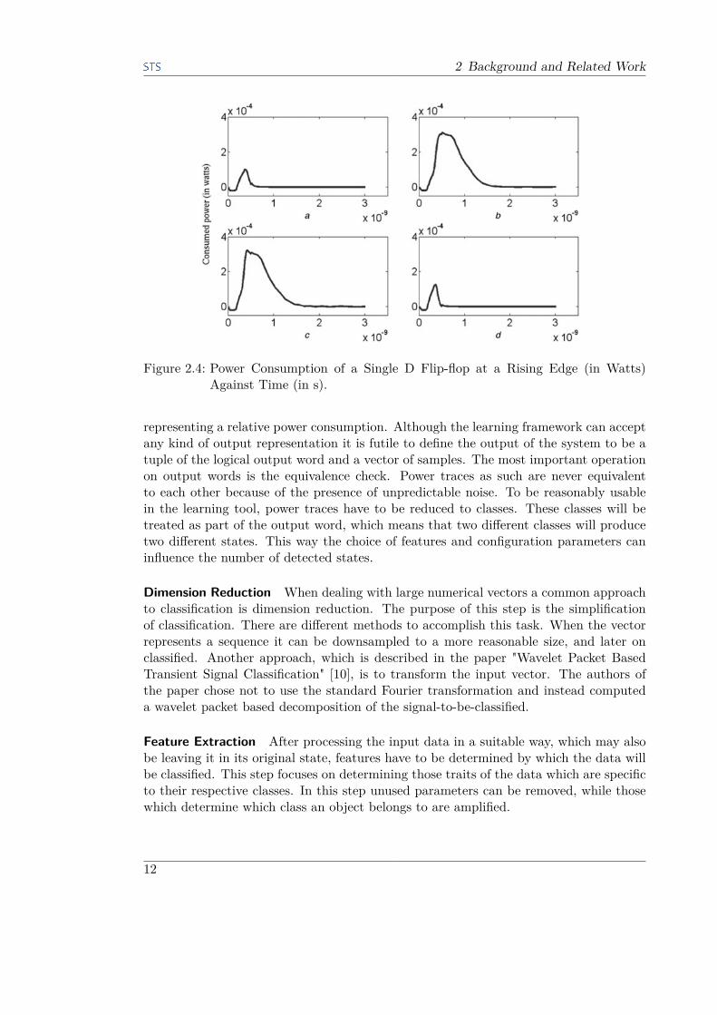
tances of the register valuations at two consecutive transitions must be one of {−1, 0,+1},as proven in Theorem 1 of [6]. Further, the register value can be obtained using PCA,given that the dynamic power consumption correlates to the previously mentioned dif-ference of Hamming distances. In their work, Zadeh and Heys performed dynamic powermeasurements on CMOS rising edge D flip-flops. A D flip-flop is a one bit memory cell.The stored value can be changed by applying the desired value to the input and togglingthe clock pin from LOW to HIGH. The results are displayed in Figure 2.4. In casea the stored value was left LOW , unchanged. In cases b and c the stored value waschanged from HIGH to LOW and LOW to HIGH. In case d the stored value was leftHIGH, unchanged. In cases b and c the dynamic power consumption has a high andbroad positive peak. In contrast, the cases a and d have small, narrow peaks. In all fourcases the peaks rise at the same time.In conclusion, the D flip-flop produces a high dynamic power consumption when the
stored value is changed. When the value stays the same, only a small peak can be seen.These findings show that there is a correlation between the dynamic power consump-tion and the IC state transitions. This data has been successfully used to break FSRencryption.
2.4 Trace ClassificationThis topic is discussed with foresight to the problem of classifying power traces, fortheir use in an automaton inference algorithm. The details of the chosen classificationmethods can be found in Section 3.2. Raw power traces are arrays of numerical values
11
2 Background and Related Work
Figure 2.4: Power Consumption of a Single D Flip-flop at a Rising Edge (in Watts)Against Time (in s).
representing a relative power consumption. Although the learning framework can acceptany kind of output representation it is futile to define the output of the system to be atuple of the logical output word and a vector of samples. The most important operationon output words is the equivalence check. Power traces as such are never equivalentto each other because of the presence of unpredictable noise. To be reasonably usablein the learning tool, power traces have to be reduced to classes. These classes will betreated as part of the output word, which means that two different classes will producetwo different states. This way the choice of features and configuration parameters caninfluence the number of detected states.
Dimension Reduction When dealing with large numerical vectors a common approachto classification is dimension reduction. The purpose of this step is the simplificationof classification. There are different methods to accomplish this task. When the vectorrepresents a sequence it can be downsampled to a more reasonable size, and later onclassified. Another approach, which is described in the paper "Wavelet Packet BasedTransient Signal Classification" [10], is to transform the input vector. The authors ofthe paper chose not to use the standard Fourier transformation and instead computeda wavelet packet based decomposition of the signal-to-be-classified.
Feature Extraction After processing the input data in a suitable way, which may alsobe leaving it in its original state, features have to be determined by which the data willbe classified. This step focuses on determining those traits of the data which are specificto their respective classes. In this step unused parameters can be removed, while thosewhich determine which class an object belongs to are amplified.
12

2.4 Trace Classification
Classification The last step in a learning problem is the actual classification, that is,assignment of classes to objects. There are lots of variations of classifiers, of which themost popular ones are the k-nearest neighbors (k-NN) algorithm, the k-means clusteringand neural networks. k-NN and neural networks require a training data set, which is acollection of labeled examples of different classes. Prior to classifying input data, thesealgorithms have to be trained, so that they can later use the learned patterns. k-NNperforms a majority vote based on the k nearest neighbors of a data point. Transformingthe data into a form suitable for distance computation is the task of feature extraction.Neural networks are modeled after the structure of a brain. They are built of layersof neurons which compute a weighted superposition of the results of the previous layer.This value is then passed through an activation function, the simplest form of which isa step function, and made available to the next layer. Neuronal networks can be usedto approximate any function. In some cases this requires immense computational effort.k-means only requires the total number of classes, k. Similar to k-NN the incomingdata points are treated as vectors, the difference of which can be computed. At first, krandom cluster centers are selected. Each incoming data point is assigned to the closestcluster, after which the cluster centers are recomputed as the averages of their members.There also exist approaches, which do not require any initial knowledge about the
domain of the data points. These we call direct feature extraction. These classificationmethods only work with numerical class labels. Such algorithms are usually very trivial,like computing the integral of a signal, counting the number of local maxima/minima ofa signal, or just returning the index of the largest/lowest element in a sequence. Oftenthe class labels produced by such classifiers are spread over a large interval. The methodsrequired to handle such a classification properly are described in Section 3.2.2.
13

3 A Sparse Alphabet and Power ChannelAnalysis
In this chapter we discuss the extensions to the L* automaton inference algorithm asit is implemented in Alice. The two major changes are the toggle alphabet and powerchannel measurement.
3.1 Toggle AlphabetThe toggle alphabet is an abstraction of the input alphabet that reduces the size ofpossible input words of an IC from 2N to N . Instead of all possible bit-vectors of lengthN , the toggle alphabet provides words to toggle each pin one at a time. The togglewords are represented as numbers in the interval [0..N). The toggle word 4 representsthe toggling of the fifth pin, without changing the values of the other pins. This way thefull input word ”1011” could be represented as the sequence [0, 2, 3]. This abstractionis valid for stateless chips, since all input words can be represented using sequences oftoggle words. Synchronous chips that have a clock pin can also be fully operated withthis alphabet. For them it does not matter in which order pins are toggled in betweentwo clock rising edges. On the other hand, chips that rely on the simultaneous togglingof multiple pins will not be learnable with this approach.The reason for choosing this abstraction is the reduction of the branching factor of the
search tree. With the full size alphabet, the set of queries generated for each new stateis 2N . Reducing this to N should increase the speed at which conjectures are reached.Also clock behavior fits well with this approach since rising/falling edges of the clock pinare clearly differentiated from other stimulations, because the clock pin is never toggledtogether with other pins. Simultaneous stimulations of the clock pin and data pins canlead to race condition or cases in which the state transition is undefined. Using thetoggle alphabet prevents these cases.In contrast to the reduction of the alphabet size, the number of states is expected to
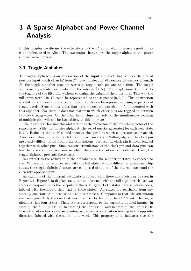
rise. While an automaton learned with the full alphabet only differentiates internal chipstates, the toggle alphabet’s states are composed of tuples of the internal state and thecurrently applied input.An example of the different automata produced with these alphabets can be seen in
Figure 3.1. Figure 3.1a displays an automaton learned with the full alphabet. It has twostates corresponding to the outputs of the NOR gate. Both states have self-transitions,labeled with the inputs that lead to these states. All states are reachable from anystate by one transition, because this chip is stateless. Compared to that, the automatonseen in Figure 3.1b, the one that was produced by learning the 74F02 with the togglealphabet, has four states. These states correspond to the currently applied inputs. Instate q0 the full input is 00. In state q1 the input is 01 and in state q3 the input is 00.Every transition has a reverse counterpart, which is a transition leading in the oppositedirection, labeled with the same input word. This property is an indicator that the
15
3 A Sparse Alphabet and Power Channel Analysis
(a) A 74F02 Chip Learned With a Full Alphabet
(b) A 74F02 Chip Learned With a Toggle Alphabet
Figure 3.1: A 74F02 Chip Learned With Different Alphabets.
Figure 3.2: A 74F02 Chip Learned With a Toggle Alphabet and Input Pins.
toggled pin does not cause internal state changes or that toggling the pin twice is anidempotent operation. When negated, this property states that pins which do not havereverse counterparts produce internal state changes. Other properties are that all stateshave N outgoing transitions, with none of them being self-transitions. Self-transitionsin automata learned with the toggle alphabet mean that the toggled pin does not haveany impact on the system’s behavior. In this case each state must have a self-transitionlabeled with that pin. If an input word only partially leads to the generation of self-transitions, then either the resulting automaton is invalid, or the pin actually triggerssystem behavior by being toggled, which is rather uncommon.
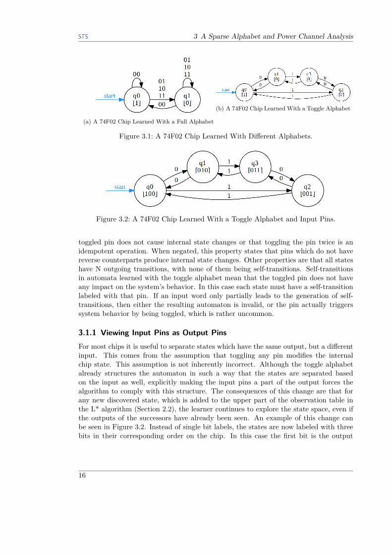
3.1.1 Viewing Input Pins as Output PinsFor most chips it is useful to separate states which have the same output, but a differentinput. This comes from the assumption that toggling any pin modifies the internalchip state. This assumption is not inherently incorrect. Although the toggle alphabetalready structures the automaton in such a way that the states are separated basedon the input as well, explicitly making the input pins a part of the output forces thealgorithm to comply with this structure. The consequences of this change are that forany new discovered state, which is added to the upper part of the observation table inthe L* algorithm (Section 2.2), the learner continues to explore the state space, even ifthe outputs of the successors have already been seen. An example of this change canbe seen in Figure 3.2. Instead of single bit labels, the states are now labeled with threebits in their corresponding order on the chip. In this case the first bit is the output
16
3.2 Power Channel Measurement
(a) A 7408 Chip Learned With-out Adding the Inputs tothe Outputs.
(b) A 7408 Chip Learned With the Inputs as Part of the Outputs.
Figure 3.3: A 7408 Chip Learned With and Without the Output Extension.
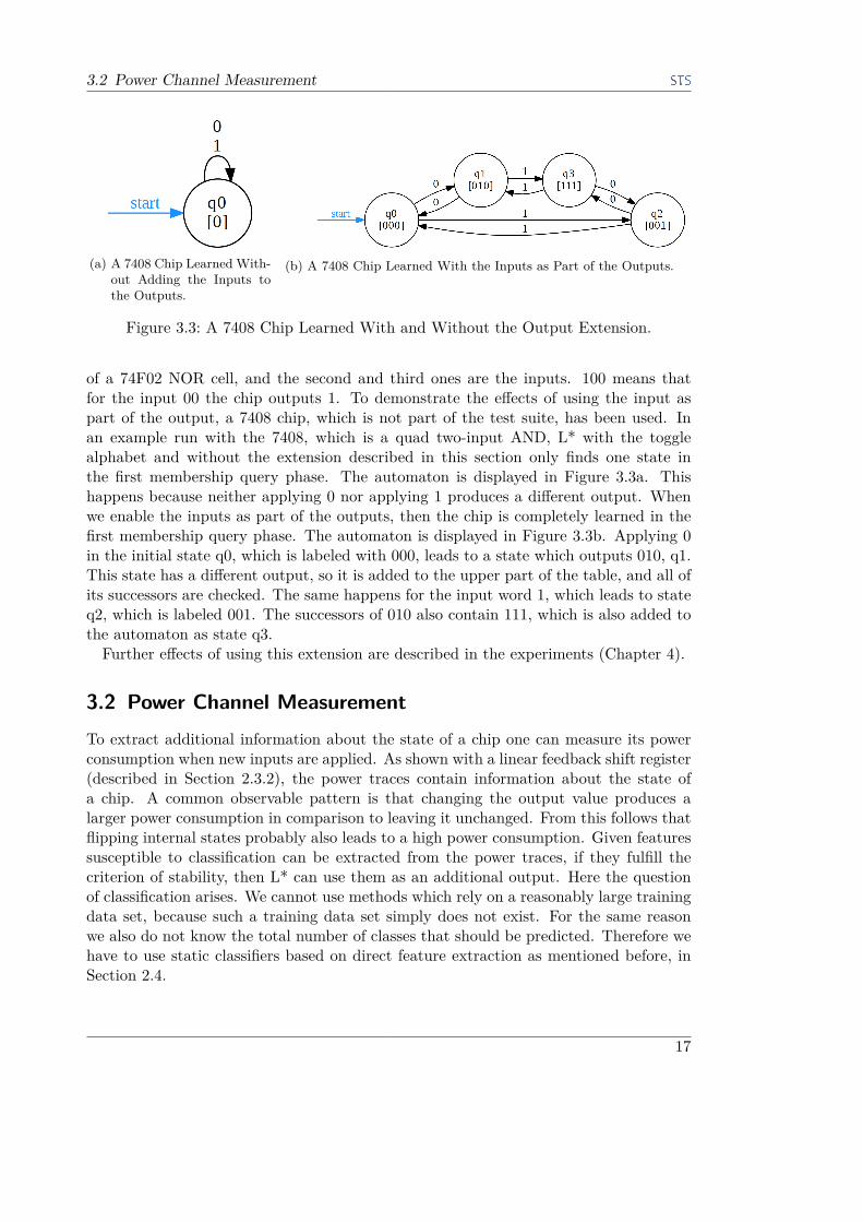
of a 74F02 NOR cell, and the second and third ones are the inputs. 100 means thatfor the input 00 the chip outputs 1. To demonstrate the effects of using the input aspart of the output, a 7408 chip, which is not part of the test suite, has been used. Inan example run with the 7408, which is a quad two-input AND, L* with the togglealphabet and without the extension described in this section only finds one state inthe first membership query phase. The automaton is displayed in Figure 3.3a. Thishappens because neither applying 0 nor applying 1 produces a different output. Whenwe enable the inputs as part of the outputs, then the chip is completely learned in thefirst membership query phase. The automaton is displayed in Figure 3.3b. Applying 0in the initial state q0, which is labeled with 000, leads to a state which outputs 010, q1.This state has a different output, so it is added to the upper part of the table, and all ofits successors are checked. The same happens for the input word 1, which leads to stateq2, which is labeled 001. The successors of 010 also contain 111, which is also added tothe automaton as state q3.Further effects of using this extension are described in the experiments (Chapter 4).
3.2 Power Channel MeasurementTo extract additional information about the state of a chip one can measure its powerconsumption when new inputs are applied. As shown with a linear feedback shift register(described in Section 2.3.2), the power traces contain information about the state ofa chip. A common observable pattern is that changing the output value produces alarger power consumption in comparison to leaving it unchanged. From this follows thatflipping internal states probably also leads to a high power consumption. Given featuressusceptible to classification can be extracted from the power traces, if they fulfill thecriterion of stability, then L* can use them as an additional output. Here the questionof classification arises. We cannot use methods which rely on a reasonably large trainingdata set, because such a training data set simply does not exist. For the same reasonwe also do not know the total number of classes that should be predicted. Therefore wehave to use static classifiers based on direct feature extraction as mentioned before, inSection 2.4.
17

3 A Sparse Alphabet and Power Channel Analysis
3.2.1 ClassifiersThe Rigol oscilloscope that has been used in the tests returns 1200 samples per trace.Each sample is returned as one unsigned byte, with 0 as the bottom of the oscilloscope’sscreen, and 255 as its top. The classifiers we are going to implement and test are thefollowing:
Const4: This classifier acts as a convenient tool to disable power trace classification.For any input it returns the value 4.
SumSqr: The SumSqr classifier subtracts the mean value from the power trace, squaresand sums the values, and returns the rounded logarithm of the resulting value.This computation is equal to a mean value free rounded logarithm of the energy ofthe signal. The mean value is subtracted to make the classification independent ofstatic power consumption which appears as a vertical offset of the signal. With anoise amplitude of two, centered on the mean value, the mean value free energy ofthe signal is at most 1200. The rounded logarithm of 1200 is 7. 7 is the smallestvalue that can be obtained with the data from the Rigol oscilloscope. The largestpossible classification number is 16. This classifier is independent of static powerconsumption (vertical offsets) as long as the measured values are not clamped tothe measured window. It is also timing insensitive (horizontal offset) as long asthe decisive part of the power trace is fully located in the captured time frame.This classifier is suitable for most kinds of signals with the exception of transient(very short) signals with a high amplitude. For regular signals the classificationsof power traces of the same class show a variation of ±1, whereas for transientsignals the variation reaches up to ±2. Due to its vertical and horizontal stability,and its low number of classes (10 in total) this classifier can be applied almosteverywhere.
IndexMin: IndexMin returns the index of the lowest measured value. The classificationscan reach from 0 to 1199. For this classifier, subtracting the mean value is notrequired, because the values are interpreted relative to each other. This classifier isalso independent on the static power consumption, for the same reason. In contrastto SumSqr this classifier excels at the classification of transient signals, but failsat empty signals. Even a transient signal has a maximum or a minimum, which isunique in most cases, but the extreme points of a noisy signal with no particularfeatures are as random as the noise itself. Another problem is the rarely occurringcase that the signal has two very close extreme points, which, superpositioned withthe noise, sometimes switch their order. Also the variance in classification resultsdepends on the chip being learned. Many chips produce a time variance of up to20 while in rare cases this value can reach 100-300. We suppose that this classifierwill be able to detect hidden states in the cascaded XOR (MC14531B), given thatits structure is the same as seen in the datasheet.
SumSqr and IndexMin are both classifiers that are based on direct feature extraction.
18
3.3 Implementation of Alice2
3.2.2 Reducing the Impact of NoiseThe classifications produced by SumSqr and IndexMin as such are not noise-resistant,which can lead to misclassifications and inconsistencies, since L* assumes that the outputof an input sequence starting from a reset-state never changes. Therefore a mechanismhas to be implemented, which reduces the divergence of classifications due to noise.
Equivalence boundary: Since the last two proposed classifiers return continuous nu-merical values, the first step to reducing noise misclassifications is an equivalenceboundary. Two classifications are regarded as equal, when their difference does notsurpass this boundary. This value is usually set to 1 or 2 for SumSqr classificationsand 20-50 for IndexMin. The equivalence boundary defines the maximum distanceof two sample clusters. Values which are further apart are considered as differentclasses.
Multisampling: Instead of querying an input sequence once, multiple samples are gath-ered. If their logical result (the output) does not match, then clearly an error hasoccurred. The mean value of the power trace classifications is returned.
Divergence boundary: If the difference between lowest and highest classification of oneinput sequence is larger than the predefined divergence boundary, then > is re-turned. > compares true with everything else. This is useful in cases where theclassification is not able to uniquely, or at least approximately, determine the classof a power trace. A prime example is the null trace classified with the IndexMinclassifier. The null trace is just noise on a straight line. Due to the noise theminimum is never in the same region. Returning the mean value as done by plainmultisampling is invalid, because the mean value itself can also vary depending onthe noise. In general the divergence boundary size defines how far apart samplesmay be, to be recognized as the same class - the maximum intra-class variance.
It is important to note that when a membership query returns > it must not bemerged with a previously found state that has the same logical output and an actualpower class. Doing this would require the power trace to always return >, which may notbe the case later on. If the new state q1 which is classified as > is considered to be equalto a previously found state q0 with an actual power classification value, than later on,if the same input sequence is tested and returns an actual power classification, it wouldhave to be equal to the power classification of state q0 with which it is not related at all.Otherwise the described situation will lead to an inconsistency of the knowledge base,or just counterexamples in an equivalence test. Both of these cases should be avoided ifpossible.
3.3 Implementation of Alice2The implementation consists of two parts: the GALEP software providing the IC inter-face and the actual framework, which is both teacher and learner. Our implementation
19

3 A Sparse Alphabet and Power Channel Analysis
of the learning framework is an extension of the Alice IC learning framework by TanyaBraun. Her implementation is in turn based on the libalf 1 framework, which is a col-lection of well-known automaton learning techniques.
Figure 3.4: The GALEP-5M.
GALEP Tester The GALEP-5M is a small computer running embedded Linux on anARM processor. The IC slot on its exterior is accessible via memory-mapped I/O, whichmeans that the pins can be read/set by reading from/writing to a specific address in thememory. The device itself is connected to the PC via a USB cable and registers itselfas a network device. The IC interface software, called tester, provides a UDP socket,on which a textual protocol is used to control the device. The following instructions areused by the learning framework.
0: Setup This message contains parameters for the overall setup, such as the Vcc voltagelevel; pin masks for Vcc, ground, input, output, and trigger pin. For our purposeswe added the option to configure delays for read and write operations.
2: Set The set message is sent along with a pin mask indicating which pins among theinput pins should be turned on/off. Prior to the write operation the write delay isapplied.
3: Get The get message returns a pin mask indicating which pins among the output pinswere active. Prior to sampling the output pins’ state the read delay is applied.
Alice2 The second part of the implementation is the learning framework. It is basedon the libalf framework, of which the L* implementation is used. The imported im-plementation only contains the learner part of the algorithm. It provides and manages
1http://libalf.informatik.rwth-aachen.de
20

3.3 Implementation of Alice2
data structures such as the knowledge base (observation table) and the automaton rep-resentation of a conjecture. The alphabet Σ is selected by specifying the alphabet sizeand a converter function f : Z|Σ| → W. The membership queries are generated by theframework as lists of integers in the range [0..(|Σ| − 1)], which can be then converted tolists of input words.The framework provides no means to run the teacher role of the algorithm. It does
not manage equivalence tests, because the equivalence test strategy depends on the typeof system which is learned. The teacher was implemented in Alice. Its interface providesa large variety of equivalence strategy configuration options. In our extension of theapplication we chose to use the full width equivalence strategy, which walks up to eachdiscovered state and compares the outputs of system and model for each input sentenceup to a certain length.
21


4 Experiments
The following section describes the experiments performed to find answers to the initiallydefined research questions.
4.1 Experiment GoalsThe goals of the experiments coincide with the following research questions.
RQ1 How can plain L* automaton learning be improved by using sparsealphabets? We learn the behavior of the ICs with the full alphabet and thetoggle alphabet and compare the results in terms of the total number of queries,the number of equivalence tests, and the correctness of the resulting automaton.
RQ2 To what extent does the power channel contain information about theIC state? We inspect whether input sequences leading to different states producedifferently classified power traces. We use the classifiers defined in Section 3.2.1 todetermine the features by which states of each chip can be differentiated.
RQ3 To what extent is it possible to classify power traces to differentiateIC states? Here we try to learn the selected ICs using the classifiers, which arefocused on different features (energy of the signal, timing). We also compare theclassification results of the two classifiers, which use power channel measurements.The intent of this research question is to determine whether the classification re-sults are meaningful for the inference of the behavior of the system.
RQ4 How can power channel analysis in combination with using a sparsealphabet be used to improve the L* automaton learning algorithm? Forthis question we compare the results of learning a chip with Alice with the resultsof learning it with Alice2.
4.2 Experiment SetupThis section describes the experiment setup with which the tests were performed.
4.2.1 Devices and ActorsThe learning test bench consists of three main devices: a PC, the GALEP-5M, and theRigol oscilloscope.The PC communicates with the IC interface using a text-based protocol over UDP.
For the role of the IC interface a Conitec GALEP-5M was chosen. It can operate ICswith up to 48 pins, that is, applying input words and reading outputs pins. For thesupport of ICs with bidirectional pins an adapter was used that maps each chip pin totwo pin slots, one for the input, one for the output, reducing the maximum IC size to 24
23

4 Experiments
pins. It also acts as a safeguard against incorrect usage of the chip. The largest testedchip had only 16 pins. Of the remaining 8 unused pins one was used as a trigger pin forthe oscilloscope.
A Rigol MSO1074Z oscilloscope is used to capture the power traces at state transitions.Prior to start measuring the chip, the oscilloscope is set up to display the power channeland the trigger channel of the chips. Of the four analogue probes of the oscilloscopethe first one was attached to the Vcc pin of the chip, which was attached to the powersupply of the GALEP via a shunt. The ground hook of the probe was attached to theground pin of the chip. The probe was set up to measure a vertical amplitude of 400mVcentered on 5.1V over a period of 2.2µs centered 200ns to the right of the trigger point.For debug purposes the trigger signal was also displayed. Its vertical amplitude was 16Vcentered on 0V. The trigger threshold was set to 3V on falling edges. The falling edgeswere chosen because they produce visibly less unnecessary fluctuations on the powerchannel, which could influence the classification results. The unit of the captured datais Volts over time units. This unit directly corresponds to the power consumption, whichis why these measurements are called power traces as well.The learning framework running on the PC submits toggle words to the IC interface.
Prior to being sent out the toggle words are converted to full sized input words. Forthat the current full input word is stored so that on new queries only the respectivepin has to be toggled. Before the last word of a query is sent, the trigger pin is set toHIGH. Then the last word, with the trigger set to LOW , is deployed. This way theoscilloscope is instructed to capture the power trace at the same time as the last inputword is applied. After each query the PC requests the captured power channel datafrom the oscilloscope which it then classifies.
4.2.2 Physical Effects
Figure 4.1: Structure of the MC14531B 12-bit Parity Tree According to its Datasheet.
24

4.2 Experiment Setup
When testing, we noticed several problems. The most important one was timing.The device used as the IC interface, the GALEP, is not able to synchronously toggleIC pins. Due to hardware limitations its 48 pin IC slot can only be accessed via threesuccessive 16 bit operations. Because of that some pins are often applied with a delayof up to 250ns. The toggle alphabet mostly solves this problem by not relying onsynchronous operations. However, commutative operations, operands of which lie indifferently delayed pin banks show unnecessary artifacts when learned with the timing-sensitive IndexMin classifier. For example the input pins of the MC14531B are locatedon both sides of the chip. According to the structure diagram of the MC14531B chip, asseen in Figure 4.1, the pins D0 - D11 have the same structure. The XOR gates used in thechip are commutative. Theoretically the propagation delay for pins D0 - D11 should bethe same, while the odd/even pin w has a shorter propagation delay. When this propertywas tested we noticed that while for some pins the power traces were classified the same,other traces were delayed by a significantly large varying offset. This problem can besolved by either using better hardware or determining, which pin slots of the GALEPcan be toggled simultaneously. With additional experiments we have determined thatthe GALEP has three pin groups, which can each be toggled simultaneously. Whenusing a time-sensitive classifier we tried to use pins, which were located in the same pingroups.Another prime example of hardware incompatibility is the 74LS259 chip. The 74LS259
8-bit addressable latch cannot be learned by the state of the art tool Alice. The L*algorithm for learning deterministic finite automata requires that the system reacts de-terministically to the input sequences. Alice assumes, that the IC interface hardwareprovides a method to simultaneously toggle multiple pins. As previous experiments haveshown, this chip can not be operated with the GALEP IC interface, because in somecases it is not possible to toggle multiple pins at the same time. The discovered faultcan be described as follows: The input pins of the chip can be split in two groups, threeaddress pins, and three instruction pins. The instruction can be one of: read, write 1,write 0, clear. Initially the chip was in a cleared state, that is, all memory bits set to0. Then the instruction write 1 was applied. After that, simultaneously the addressbits were changed and the instruction was switched to read. Due to imprecise driverhardware the last instruction was split into two parts. The part containing the addressbits was flipped first, and then, with a small delay, the instruction bits were flipped.The delay was large enough for the chip to interpret the intermediary input as the nextinput. The register value at the new address, which should have been left unchanged,was overwritten by 1. This problem can be solved by using the toggle alphabet, whichdoes not contain words, which require the simultaneous toggling of multiple pins.A similar time-related problem is buffering. Sometimes the MC14531B cascaded XOR
chip produced visibly different power traces and incorrect logical outputs for the sameinput sequence. We suppose that the reason for that is the buffering of requests on thePC. The MC14531B has a relatively high propagation delay. When the instructions forthe IC interface were manually sent one at a time the results were deterministic andcorrect. Probably, due to buffering or very fast execution of sequences of operations, thepropagation delay was undershot, which lead to incorrect and nondeterministic results.
25
4 Experiments
We resolved this problem by adding a configurable pre-operation delay in the IC interface.We observed similar problems with the Rigol oscilloscope. The selected mode of oper-
ation, which is described in Section 4.2.1, is not intended for high-speed applications. Inrare cases the oscilloscope did not trigger on new inputs, or returned old measurements,that were still buffered. This behavior can be attributed to a missing delay betweenoperations, and was prevented, by adding delays before read operations. This changesignificantly reduces the speed at which queries can be asked.
Limitations of Setup The primary limitation of the selected setup is speed/time. Withthe exception of the MC14531B chip, all chips could be operated at a much higherfrequency without power channel analysis, and even faster than it was possible with theGALEP IC interface. This limitation obstructed testing in that only small input pinsets of up to 6 with PCA and 12 without PCA could be tested, whereas running thetests with large input sets or ICs with complex logic functions mostly did not terminatewithin hours.
The GALEP is not well suited for testing synchronous chips with the full alphabet aspreviously mentioned, due to the lack of pin access synchronicity.
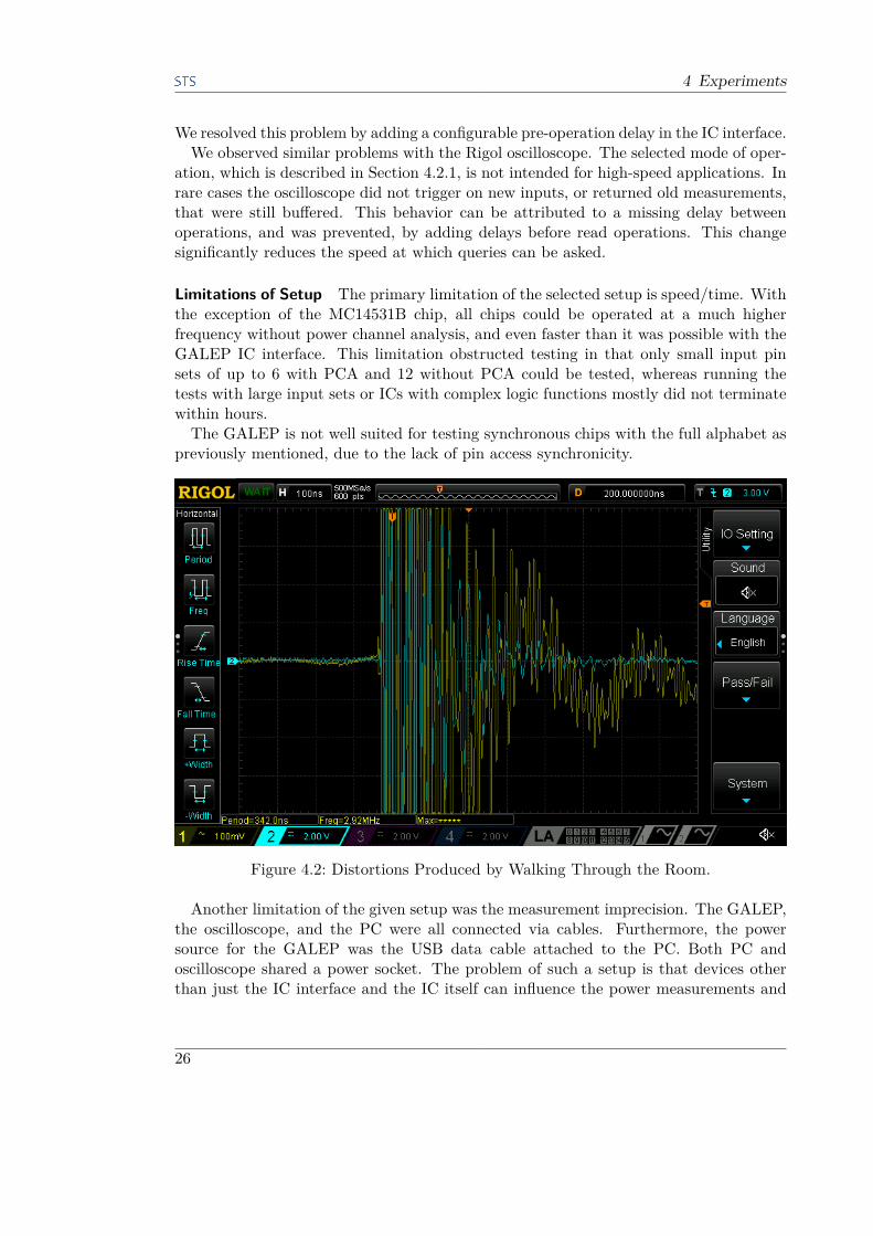
Figure 4.2: Distortions Produced by Walking Through the Room.
Another limitation of the given setup was the measurement imprecision. The GALEP,the oscilloscope, and the PC were all connected via cables. Furthermore, the powersource for the GALEP was the USB data cable attached to the PC. Both PC andoscilloscope shared a power socket. The problem of such a setup is that devices otherthan just the IC interface and the IC itself can influence the power measurements and
26

4.3 Raw Results
produce significantly large artifacts. Often, when no tests were run and the IC was notpowered, plugging other devices into the power socket or the USB socket of the PC, orjust moving around the room, produced measurements such as the one in Figure 4.2.
4.3 Raw ResultsWe now describe the raw results obtained by learning the chips from the representativetest suite with different tools and configurations. The case analysis is performed inSection 4.4. The tables displaying the performance results are structured in the way thatthe left side of the table up to the double line contains the configuration parameters,while the right side contains the observed results. This section is split in two parts - inthe first part we try to learn the selected chips using Alice, which is the predecessor ofour implementation, in the second part we use our tool Alice2.Both tools require configuration parameters. These include the depth of equivalence
tests, and values for the divergence and equivalence boundaries. In the tests run withAlice, the default equivalence strategy, which tests the whole alphabet to a depth of two,has been used. In some cases the depth has been increased to three, to test whetherthis will uncover additional states, which were not found with the smaller depth. InAlice2 a similar range has been adopted for this value. When the input was consideredas part of the output, an equivalence test depth of two was sufficient for the chips inthe representative test suite. Without this extension, a larger depth has to be used.An equivalence depth of two for a full-sized alphabet is only achievable by the togglealphabet with a depth of 2 ∗ |Σ|. In practice it is more efficient to view the inputs asoutputs.The values for the divergence and equivalence boundaries used in the classifiers depend
on the classifier and the chip. Each chip in the representative test suite has its ownpower trace characteristics, for which these values have to be adjusted. These valueswere chosen based on previous tests.
4.3.1 State of the Art: AliceHere we describe the results of learning some chips from the test suite using Alice, thepredecessor of our research. In Section 4.4 these results are used for comparing Alice andAlice2. Most tables displayed in this section have the following columns: a configurationparameter, and the equality test depth (EQ depth) on the left side and the number ofstates, the total number of queries, the number of membership queries (MEM q.), andthe number of equality tests (EQ tests) on the right.
DL155D Only one of the two decoder blocks of this chip has been used. The enableand output pins of the second decoder were disabled. Table 4.1 shows the performanceresults of learning the DL155D IC with the tool Alice. The configuration parameter ofthis chip is the number of used address pins (#Addr). The equality depth has been setto 2. The number of states and the number of queries grow exponentially with regardto the number of enabled address pins. In each run only one equality test was required.
27
4 Experiments
#Addr EQ depth States Queries MEM q. EQ tests0 2 2 39 9 11 2 3 204 25 12 2 5 1302 81 1
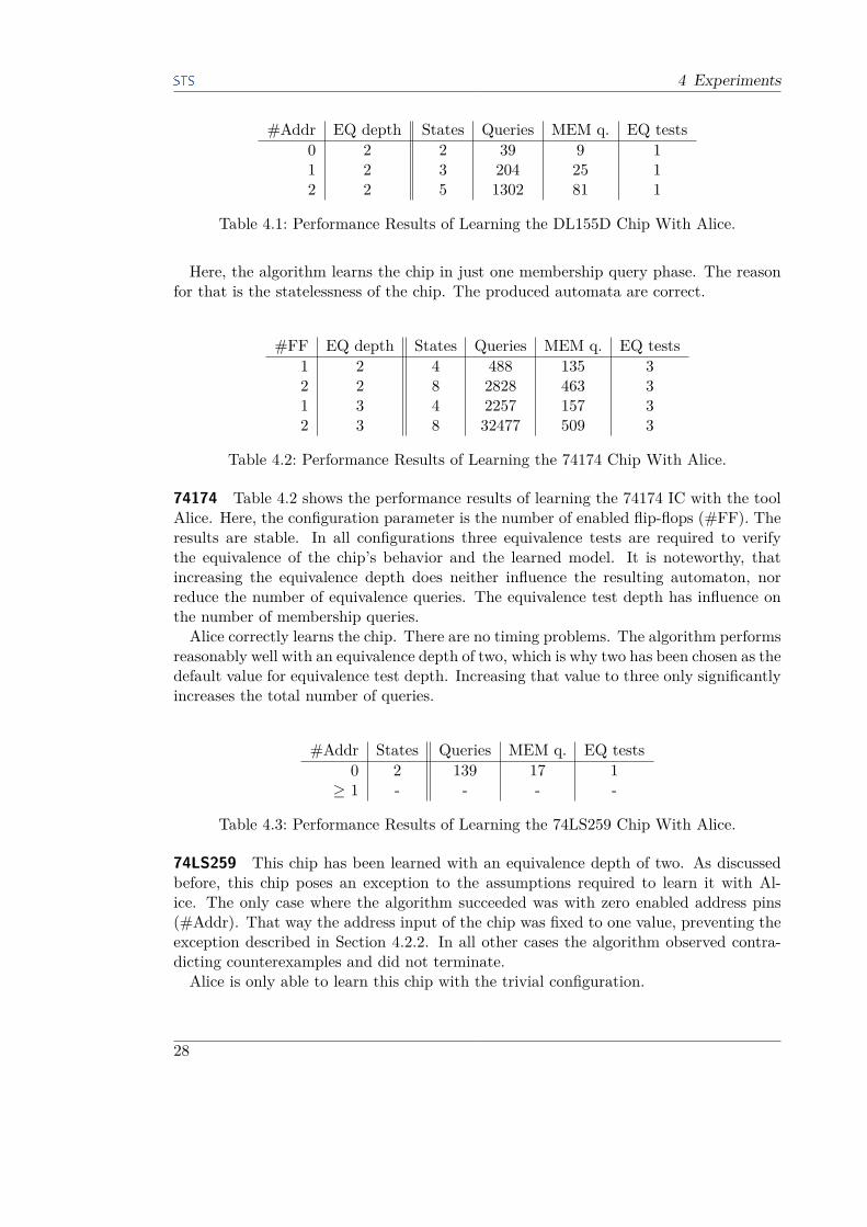
Table 4.1: Performance Results of Learning the DL155D Chip With Alice.
Here, the algorithm learns the chip in just one membership query phase. The reasonfor that is the statelessness of the chip. The produced automata are correct.
#FF EQ depth States Queries MEM q. EQ tests1 2 4 488 135 32 2 8 2828 463 31 3 4 2257 157 32 3 8 32477 509 3
Table 4.2: Performance Results of Learning the 74174 Chip With Alice.
74174 Table 4.2 shows the performance results of learning the 74174 IC with the toolAlice. Here, the configuration parameter is the number of enabled flip-flops (#FF). Theresults are stable. In all configurations three equivalence tests are required to verifythe equivalence of the chip’s behavior and the learned model. It is noteworthy, thatincreasing the equivalence depth does neither influence the resulting automaton, norreduce the number of equivalence queries. The equivalence test depth has influence onthe number of membership queries.Alice correctly learns the chip. There are no timing problems. The algorithm performs
reasonably well with an equivalence depth of two, which is why two has been chosen as thedefault value for equivalence test depth. Increasing that value to three only significantlyincreases the total number of queries.
#Addr States Queries MEM q. EQ tests0 2 139 17 1
≥ 1 - - - -
Table 4.3: Performance Results of Learning the 74LS259 Chip With Alice.
74LS259 This chip has been learned with an equivalence depth of two. As discussedbefore, this chip poses an exception to the assumptions required to learn it with Al-ice. The only case where the algorithm succeeded was with zero enabled address pins(#Addr). That way the address input of the chip was fixed to one value, preventing theexception described in Section 4.2.2. In all other cases the algorithm observed contra-dicting counterexamples and did not terminate.Alice is only able to learn this chip with the trivial configuration.
28
4.3 Raw Results
4.3.2 Alice2Next we display the results of learning the chips from the test suite using Alice2. If notexplicitly defined otherwise, the equivalence test depth is set to two.
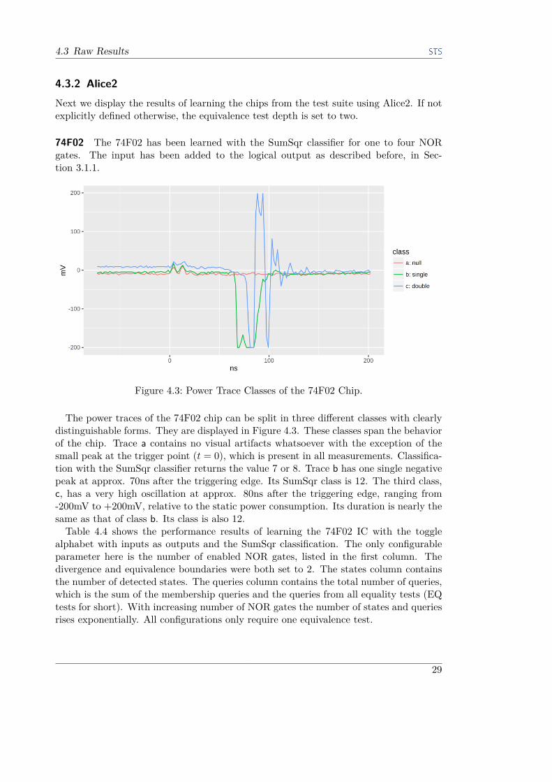
74F02 The 74F02 has been learned with the SumSqr classifier for one to four NORgates. The input has been added to the logical output as described before, in Sec-tion 3.1.1.
Figure 4.3: Power Trace Classes of the 74F02 Chip.
The power traces of the 74F02 chip can be split in three different classes with clearlydistinguishable forms. They are displayed in Figure 4.3. These classes span the behaviorof the chip. Trace a contains no visual artifacts whatsoever with the exception of thesmall peak at the trigger point (t = 0), which is present in all measurements. Classifica-tion with the SumSqr classifier returns the value 7 or 8. Trace b has one single negativepeak at approx. 70ns after the triggering edge. Its SumSqr class is 12. The third class,c, has a very high oscillation at approx. 80ns after the triggering edge, ranging from-200mV to +200mV, relative to the static power consumption. Its duration is nearly thesame as that of class b. Its class is also 12.
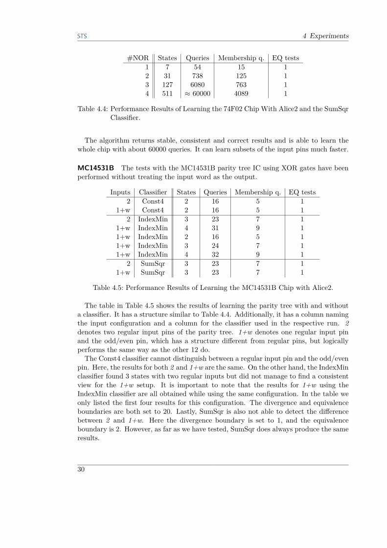
Table 4.4 shows the performance results of learning the 74F02 IC with the togglealphabet with inputs as outputs and the SumSqr classification. The only configurableparameter here is the number of enabled NOR gates, listed in the first column. Thedivergence and equivalence boundaries were both set to 2. The states column containsthe number of detected states. The queries column contains the total number of queries,which is the sum of the membership queries and the queries from all equality tests (EQtests for short). With increasing number of NOR gates the number of states and queriesrises exponentially. All configurations only require one equivalence test.
29
4 Experiments
#NOR States Queries Membership q. EQ tests1 7 54 15 12 31 738 125 13 127 6080 763 14 511 ≈ 60000 4089 1
Table 4.4: Performance Results of Learning the 74F02 Chip With Alice2 and the SumSqrClassifier.
The algorithm returns stable, consistent and correct results and is able to learn thewhole chip with about 60000 queries. It can learn subsets of the input pins much faster.
MC14531B The tests with the MC14531B parity tree IC using XOR gates have beenperformed without treating the input word as the output.
Inputs Classifier States Queries Membership q. EQ tests2 Const4 2 16 5 1
1+w Const4 2 16 5 12 IndexMin 3 23 7 1
1+w IndexMin 4 31 9 11+w IndexMin 2 16 5 11+w IndexMin 3 24 7 11+w IndexMin 4 32 9 1
2 SumSqr 3 23 7 11+w SumSqr 3 23 7 1
Table 4.5: Performance Results of Learning the MC14531B Chip with Alice2.
The table in Table 4.5 shows the results of learning the parity tree with and withouta classifier. It has a structure similar to Table 4.4. Additionally, it has a column namingthe input configuration and a column for the classifier used in the respective run. 2denotes two regular input pins of the parity tree. 1+w denotes one regular input pinand the odd/even pin, which has a structure different from regular pins, but logicallyperforms the same way as the other 12 do.The Const4 classifier cannot distinguish between a regular input pin and the odd/even
pin. Here, the results for both 2 and 1+w are the same. On the other hand, the IndexMinclassifier found 3 states with two regular inputs but did not manage to find a consistentview for the 1+w setup. It is important to note that the results for 1+w using theIndexMin classifier are all obtained while using the same configuration. In the table weonly listed the first four results for this configuration. The divergence and equivalenceboundaries are both set to 20. Lastly, SumSqr is also not able to detect the differencebetween 2 and 1+w. Here the divergence boundary is set to 1, and the equivalenceboundary is 2. However, as far as we have tested, SumSqr does always produce the sameresults.
30
4.3 Raw Results
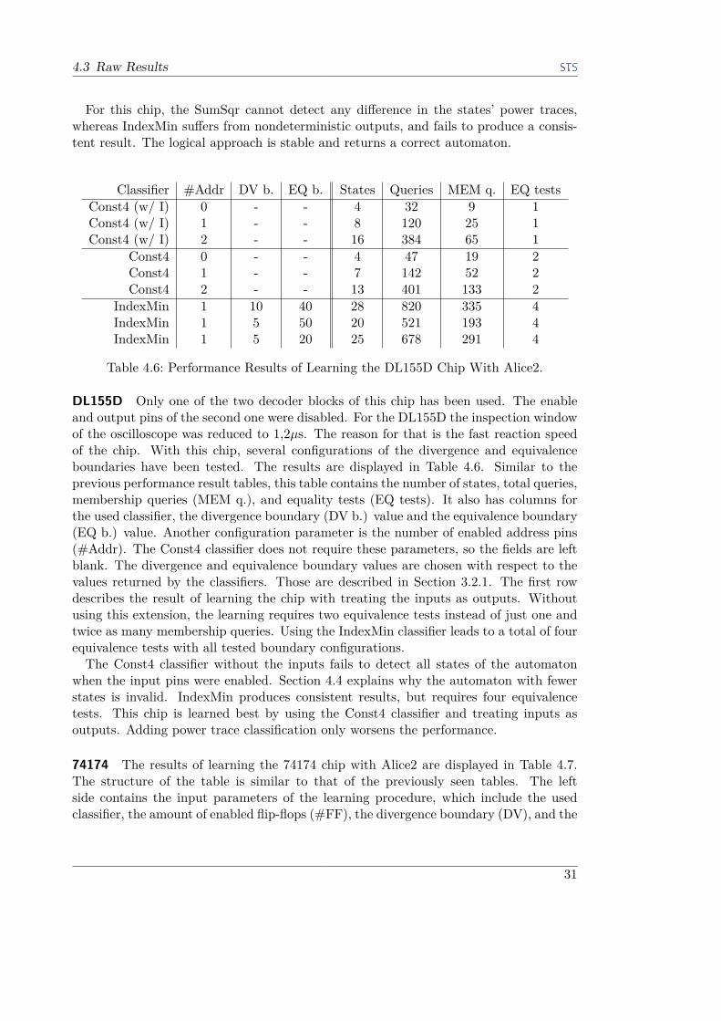
For this chip, the SumSqr cannot detect any difference in the states’ power traces,whereas IndexMin suffers from nondeterministic outputs, and fails to produce a consis-tent result. The logical approach is stable and returns a correct automaton.
Classifier #Addr DV b. EQ b. States Queries MEM q. EQ testsConst4 (w/ I) 0 - - 4 32 9 1Const4 (w/ I) 1 - - 8 120 25 1Const4 (w/ I) 2 - - 16 384 65 1
Const4 0 - - 4 47 19 2Const4 1 - - 7 142 52 2Const4 2 - - 13 401 133 2
IndexMin 1 10 40 28 820 335 4IndexMin 1 5 50 20 521 193 4IndexMin 1 5 20 25 678 291 4
Table 4.6: Performance Results of Learning the DL155D Chip With Alice2.
DL155D Only one of the two decoder blocks of this chip has been used. The enableand output pins of the second one were disabled. For the DL155D the inspection windowof the oscilloscope was reduced to 1,2µs. The reason for that is the fast reaction speedof the chip. With this chip, several configurations of the divergence and equivalenceboundaries have been tested. The results are displayed in Table 4.6. Similar to theprevious performance result tables, this table contains the number of states, total queries,membership queries (MEM q.), and equality tests (EQ tests). It also has columns forthe used classifier, the divergence boundary (DV b.) value and the equivalence boundary(EQ b.) value. Another configuration parameter is the number of enabled address pins(#Addr). The Const4 classifier does not require these parameters, so the fields are leftblank. The divergence and equivalence boundary values are chosen with respect to thevalues returned by the classifiers. Those are described in Section 3.2.1. The first rowdescribes the result of learning the chip with treating the inputs as outputs. Withoutusing this extension, the learning requires two equivalence tests instead of just one andtwice as many membership queries. Using the IndexMin classifier leads to a total of fourequivalence tests with all tested boundary configurations.The Const4 classifier without the inputs fails to detect all states of the automaton
when the input pins were enabled. Section 4.4 explains why the automaton with fewerstates is invalid. IndexMin produces consistent results, but requires four equivalencetests. This chip is learned best by using the Const4 classifier and treating inputs asoutputs. Adding power trace classification only worsens the performance.
74174 The results of learning the 74174 chip with Alice2 are displayed in Table 4.7.The structure of the table is similar to that of the previously seen tables. The leftside contains the input parameters of the learning procedure, which include the usedclassifier, the amount of enabled flip-flops (#FF), the divergence boundary (DV), and the
31

4 Experiments
Classifier #FF DV EQ States Queries MEM q. EQ testsConst4 (w/ I) 1 - - 12 504 37 1Const4 (w/ I) 2 - - 40 3520 161 1Const4 (w/ I) 3 - - 144 23040 721 1
Const4 1 - - 12 1177 297 5Const4 2 - - 40 6679 1133 5Const4 3 - - 144 39903 4925 5
SumSqr (w/ I) 1 0 3 39 894 276 2SumSqr (w/ I) 1 0 3 ≥ 124 ≥ 2355 ≥ 1507 ≥ 3SumSqr (w/ I) 1 1 3 - - - -
IndexMin (w/ I) 1 10 400 21 877 64 1IndexMin (w/ I) 1 10 400 23 960 70 1IndexMin (w/ I) 1 10 100 24 1002 73 1IndexMin (w/ I) 1 10 100 28 1171 85 1IndexMin (w/ I) 1 5 50 28 1168 85 1
IndexMin 1 10 400 ≥ 88 ≥ 1694 ≥ 1285 ≥ 4IndexMin 1 5 50 ≥ 104 ≥ 4155 ≥ 3327 ≥ 4
Table 4.7: Performance Results of Learning the 74174 Chip With Alice2.
equivalence boundary (EQ). The right side of the table contains the actual performanceresults, which are measured by the number of states of the resulting automaton, thetotal number of queries, the number of membership queries (MEM q.), and the numberof equality tests (EQ tests). The 74174 is the first stateful IC tested with this newapproach. Here the equivalence depth has been set to three. In the first part the chipis tested without power classification. For one to three active flip-flops the algorithmrequires just one equivalence query. Still, the number of queries and states grows fasterthan for the tested stateless chips. It took the algorithm 30 minutes to learn the chipwith just three flip-flops. Without the inputs the procedure requires 50 minutes. Also,without the inputs the number of equivalence tests increases to five, for any number ofenabled flip-flops. Compared to the results with inputs, the total number of queries isapproximately doubled, while the number of membership queries is increased roughlyby a factor of 8.The automaton produced by running the algorithm with the SumSqr algorithm with
a divergence boundary of zero had more than three times as many states as without thepower classification. When executed again, the same configuration did not terminate,as it produced many more states than expected. Increasing the divergence boundary toone resulted in an inconsistent counterexample with different power classifications. Dueto this problem this configuration was not run without the inputs in the outputs.In contrast to the unstable results of the SumSqr classifier, IndexMin, although un-
stable as well, converged to an automaton with 23 states with a very high equivalenceboundary. The runs without the inputs were aborted due to an unreasonably largenumber of membership queries.
32
4.4 Case Analyses and Interpretations
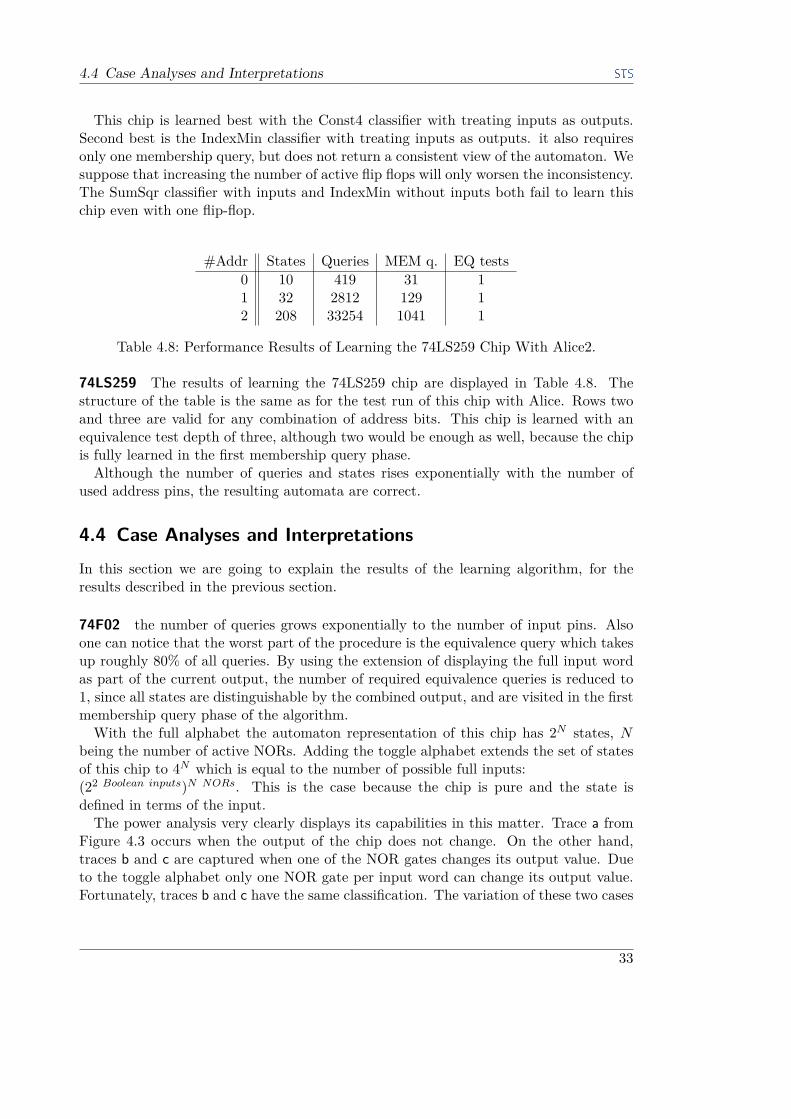
This chip is learned best with the Const4 classifier with treating inputs as outputs.Second best is the IndexMin classifier with treating inputs as outputs. it also requiresonly one membership query, but does not return a consistent view of the automaton. Wesuppose that increasing the number of active flip flops will only worsen the inconsistency.The SumSqr classifier with inputs and IndexMin without inputs both fail to learn thischip even with one flip-flop.
#Addr States Queries MEM q. EQ tests0 10 419 31 11 32 2812 129 12 208 33254 1041 1
Table 4.8: Performance Results of Learning the 74LS259 Chip With Alice2.
74LS259 The results of learning the 74LS259 chip are displayed in Table 4.8. Thestructure of the table is the same as for the test run of this chip with Alice. Rows twoand three are valid for any combination of address bits. This chip is learned with anequivalence test depth of three, although two would be enough as well, because the chipis fully learned in the first membership query phase.Although the number of queries and states rises exponentially with the number of
used address pins, the resulting automata are correct.
4.4 Case Analyses and InterpretationsIn this section we are going to explain the results of the learning algorithm, for theresults described in the previous section.
74F02 the number of queries grows exponentially to the number of input pins. Alsoone can notice that the worst part of the procedure is the equivalence query which takesup roughly 80% of all queries. By using the extension of displaying the full input wordas part of the current output, the number of required equivalence queries is reduced to1, since all states are distinguishable by the combined output, and are visited in the firstmembership query phase of the algorithm.With the full alphabet the automaton representation of this chip has 2N states, N
being the number of active NORs. Adding the toggle alphabet extends the set of statesof this chip to 4N which is equal to the number of possible full inputs:(22 Boolean inputs)N NORs. This is the case because the chip is pure and the state isdefined in terms of the input.The power analysis very clearly displays its capabilities in this matter. Trace a from
Figure 4.3 occurs when the output of the chip does not change. On the other hand,traces b and c are captured when one of the NOR gates changes its output value. Dueto the toggle alphabet only one NOR gate per input word can change its output value.Fortunately, traces b and c have the same classification. The variation of these two cases
33
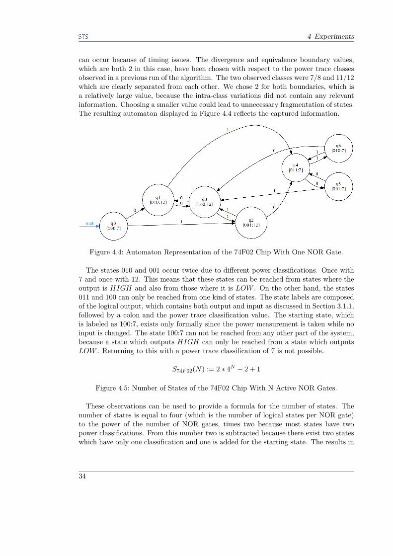
4 Experiments
can occur because of timing issues. The divergence and equivalence boundary values,which are both 2 in this case, have been chosen with respect to the power trace classesobserved in a previous run of the algorithm. The two observed classes were 7/8 and 11/12which are clearly separated from each other. We chose 2 for both boundaries, which isa relatively large value, because the intra-class variations did not contain any relevantinformation. Choosing a smaller value could lead to unnecessary fragmentation of states.The resulting automaton displayed in Figure 4.4 reflects the captured information.
Figure 4.4: Automaton Representation of the 74F02 Chip With One NOR Gate.
The states 010 and 001 occur twice due to different power classifications. Once with7 and once with 12. This means that these states can be reached from states where theoutput is HIGH and also from those where it is LOW . On the other hand, the states011 and 100 can only be reached from one kind of states. The state labels are composedof the logical output, which contains both output and input as discussed in Section 3.1.1,followed by a colon and the power trace classification value. The starting state, whichis labeled as 100:7, exists only formally since the power measurement is taken while noinput is changed. The state 100:7 can not be reached from any other part of the system,because a state which outputs HIGH can only be reached from a state which outputsLOW . Returning to this with a power trace classification of 7 is not possible.
S74F 02(N) := 2 ∗ 4N − 2 + 1
Figure 4.5: Number of States of the 74F02 Chip With N Active NOR Gates.
These observations can be used to provide a formula for the number of states. Thenumber of states is equal to four (which is the number of logical states per NOR gate)to the power of the number of NOR gates, times two because most states have twopower classifications. From this number two is subtracted because there exist two stateswhich have only one classification and one is added for the starting state. The results in
34

4.4 Case Analyses and Interpretations
Table 4.4 confirm this formula.Compared to learning this chip with Alice, the results of which are not displayed in
this work, Alice2 performs much better, even with the power channel analysis. Thepower traces indicate whether the output has changed.
MC14531B The behavior of the Const4 classifier, which is displayed in Table 4.5, canbe explained by the logical equality of the behavior of regular pins and the odd/evenpin. Both produce the exact same behavior on the logic output channel. On the otherhand, the IndexMin approach has more states in both cases. With two regular pins thealgorithm always returns an automaton with three states. The additional third stateappears because the classification for the empty sentence diverges to >, while all otherinputs produce traces of the same class. Since the logic output is either 0 or 1, two morestates are generated. For the 1+w case there is no unique representation. Often thetraces’ positions vary for the same input sequence, which makes it impossible to classifythem consistently. The reason for the varying timing is the delay in the GALEP.
Figure 4.6: Automaton Representation of the MC14531B Chip With Any Two InputPins Learned With the SumSqr Classifier.
The SumSqr classifier, which is not timing sensitive produces stable results for both2 and 1+w. The result of either of those configurations can be seen in Figure 4.6.The only information gain which is achieved by using SumSqr is that all active powertraces have a higher power consumption than the passive null trace. If the output isHIGH, then power consumption is also relatively high (11). When the output is LOW ,then the power consumption is also low. These obtained results also mean that thepower consumption of the MC14531B is dominated by the output bit and that it doesnot contain significant information for the detection of the odd/even pin using a signalenergy based classifier like SumSqr.For this chip, using the SumSqr classifier is meaningless, since the power traces cor-
respond to the output of the chip. A refined version of IndexMin or another time-basedclassifier could determine the difference between a regular pin and the odd/even pin, ifthe interface hardware would act deterministically.
DL155D The DL155D chip is also a stateless chip, meaning that checking the wholeinput alphabet will reveal all relevant states. This is why using the Const4 classifier withtreating the inputs as outputs results in eight states and only one equivalence test. Therows of Table 4.6, where the Const4 classifier has been used without the inputs as partof the state labels, indicate that this chip has states from which two toggle transitions
35
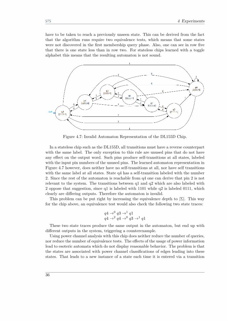
4 Experiments
have to be taken to reach a previously unseen state. This can be derived from the factthat the algorithm runs require two equivalence tests, which means that some stateswere not discovered in the first membership query phase. Also, one can see in row fivethat there is one state less than in row two. For stateless chips learned with a togglealphabet this means that the resulting automaton is not sound.
Figure 4.7: Invalid Automaton Representation of the DL155D Chip.
In a stateless chip such as the DL155D, all transitions must have a reverse counterpartwith the same label. The only exception to this rule are unused pins that do not haveany effect on the output word. Such pins produce self-transitions at all states, labeledwith the input pin numbers of the unused pins. The learned automaton representation inFigure 4.7 however, does neither have no self-transitions at all, nor have self transitionswith the same label at all states. State q4 has a self-transition labeled with the number2. Since the rest of the automaton is reachable from q4 one can derive that pin 2 is notrelevant to the system. The transitions between q1 and q2 which are also labeled with2 oppose that suggestion, since q1 is labeled with 1101 while q2 is labeled 0111, whichclearly are differing outputs. Therefore the automaton is invalid.This problem can be put right by increasing the equivalence depth to |Σ|. This way
for the chip above, an equivalence test would also check the following two state traces:
q4→0 q3→1 q1q4→2 q4→0 q3→1 q1
These two state traces produce the same output in the automaton, but end up withdifferent outputs in the system, triggering a counterexample.Using power channel analysis with this chip does neither reduce the number of queries,
nor reduce the number of equivalence tests. The effects of the usage of power informationlead to esoteric automata which do not display reasonable behavior. The problem is thatthe states are associated with power channel classifications of edges leading into thesestates. That leads to a new instance of a state each time it is entered via a transition
36
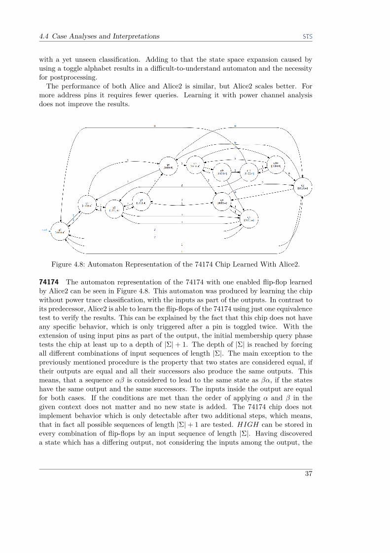
4.4 Case Analyses and Interpretations
with a yet unseen classification. Adding to that the state space expansion caused byusing a toggle alphabet results in a difficult-to-understand automaton and the necessityfor postprocessing.The performance of both Alice and Alice2 is similar, but Alice2 scales better. For
more address pins it requires fewer queries. Learning it with power channel analysisdoes not improve the results.
Figure 4.8: Automaton Representation of the 74174 Chip Learned With Alice2.
74174 The automaton representation of the 74174 with one enabled flip-flop learnedby Alice2 can be seen in Figure 4.8. This automaton was produced by learning the chipwithout power trace classification, with the inputs as part of the outputs. In contrast toits predecessor, Alice2 is able to learn the flip-flops of the 74174 using just one equivalencetest to verify the results. This can be explained by the fact that this chip does not haveany specific behavior, which is only triggered after a pin is toggled twice. With theextension of using input pins as part of the output, the initial membership query phasetests the chip at least up to a depth of |Σ| + 1. The depth of |Σ| is reached by forcingall different combinations of input sequences of length |Σ|. The main exception to thepreviously mentioned procedure is the property that two states are considered equal, iftheir outputs are equal and all their successors also produce the same outputs. Thismeans, that a sequence αβ is considered to lead to the same state as βα, if the stateshave the same output and the same successors. The inputs inside the output are equalfor both cases. If the conditions are met than the order of applying α and β in thegiven context does not matter and no new state is added. The 74174 chip does notimplement behavior which is only detectable after two additional steps, which means,that in fact all possible sequences of length |Σ|+ 1 are tested. HIGH can be stored inevery combination of flip-flops by an input sequence of length |Σ|. Having discovereda state which has a differing output, not considering the inputs among the output, the
37

4 Experiments
depth rule once again applies. Thus, the behavior of the chip is learned with only oneequivalence test. The automaton derived in the first membership query phase is valid.
A feature which is clearly visible in the automaton in Figure 4.8 are the transitionswhich cause internal state changes. In stateless chips, all transitions have reverse coun-terparts with the same label. Here, some pins, like for example pin 1, always have areverse counterpart, while 0 and 2 do not. Pin 0 is the enable (negative clear) pin. Whenit is turned off, the internal state of the chip is lost. Turning it on again afterwards willlead to a different state, if the previously stored value was HIGH. Pin 2 is the clockpin. At rising edges the value of the data pin (1) is stored in the corresponding flip-flop,causing an internal state change if the previously stored value was different. Continu-ing to toggle the clock pin after that has no effect on the inner state whatsoever. Thedata pin, on the other hand, does never trigger an internal state change. Toggling ittwice is always an idempotent operation. In the tests with power trace classification theautomata also have transitions with reverse counterparts, but are mostly composed ofunidentifiable structures.The tests with the SumSqr classifier have shown that for some cases even the SumSqr
classifier produces major unstable results. We inspected the input sequence, which leadto contradicting counterexamples due to different power classifications, and found thatits power traces looked similar to each other. The reason for the imprecise classificationcould be that the sequence caused a state transition which produced long-term effectson the power channel, relative to the observation window. The SumSqr classifier wasnot able to deduce the equivalence of these classes.In contrast to that, the Alice2 algorithm run with the IndexMin classifier terminated.
Even with using a very high equivalence boundary it discovered some more states thanConst4. Reducing the equivalence boundary by 300 to a value of 100 added some morestates. It is interesting, that for some input sequences the resulting classifications werealways exactly the same. This, however did not empower this classifier to be of anyuse when learning the chip without the inputs. The number of membership queriesby far surpassed the values from IndexMin with inputs, and the tests were thereforeaborted. However, similar to the runs with Const4, IndexMin classifications also leadto performing exactly one equivalence check for all tested configurations with inputs.We suppose, that the aborted runs would also would also require five equivalence tests,similar to Const4 without inputs. We come to the conclusion, that analyzing the poweronly adds unnecessary details, which obfuscate the resulting automaton, while using nopower trace classification produces correct automata with the least states by using theleast amount of queries.Without the power channel classification, Alice2 requires three times less member-
ship queries than Alice. Here the toggle alphabet displays its potential of intelligentlyexploring the state space, contrary to the brute-force approach. With an equivalencetest depth of two, Alice has less queries in total, which is explained by the differencein the equality test depth setting, which is set to three in Alice2. The depth settingcannot be directly compared, because of the properties of the corresponding alphabets,as explained in Section 3.1. Theoretically the equivalence query in Alice2 can be omit-ted from the total number of queries, since the first membership query phase already
38
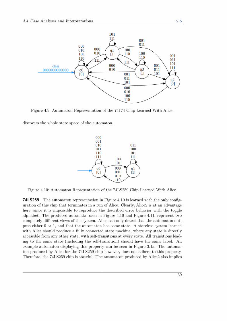
4.4 Case Analyses and Interpretations
Figure 4.9: Automaton Representation of the 74174 Chip Learned With Alice.
discovers the whole state space of the automaton.
Figure 4.10: Automaton Representation of the 74LS259 Chip Learned With Alice.
74LS259 The automaton representation in Figure 4.10 is learned with the only config-uration of this chip that terminates in a run of Alice. Clearly, Alice2 is at an advantagehere, since it is impossible to reproduce the described error behavior with the togglealphabet. The produced automata, seen in Figure 4.10 and Figure 4.11, represent twocompletely different views of the system. Alice can only detect that the automaton out-puts either 0 or 1, and that the automaton has some state. A stateless system learnedwith Alice should produce a fully connected state machine, where any state is directlyaccessible from any other state, with self-transitions at every state. All transitions lead-ing to the same state (including the self-transition) should have the same label. Anexample automaton displaying this property can be seen in Figure 3.1a. The automa-ton produced by Alice for the 74LS259 chip however, does not adhere to this property.Therefore, the 74LS259 chip is stateful. The automaton produced by Alice2 also implies
39
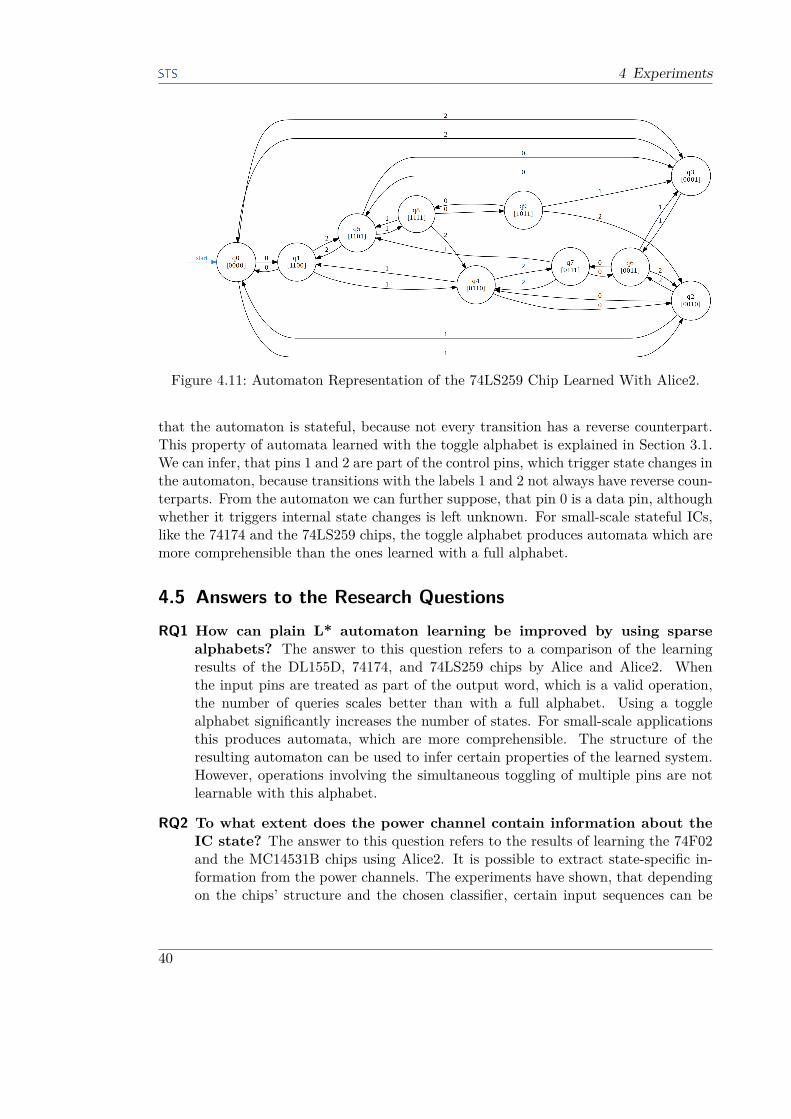
4 Experiments
Figure 4.11: Automaton Representation of the 74LS259 Chip Learned With Alice2.
that the automaton is stateful, because not every transition has a reverse counterpart.This property of automata learned with the toggle alphabet is explained in Section 3.1.We can infer, that pins 1 and 2 are part of the control pins, which trigger state changes inthe automaton, because transitions with the labels 1 and 2 not always have reverse coun-terparts. From the automaton we can further suppose, that pin 0 is a data pin, althoughwhether it triggers internal state changes is left unknown. For small-scale stateful ICs,like the 74174 and the 74LS259 chips, the toggle alphabet produces automata which aremore comprehensible than the ones learned with a full alphabet.
4.5 Answers to the Research QuestionsRQ1 How can plain L* automaton learning be improved by using sparse
alphabets? The answer to this question refers to a comparison of the learningresults of the DL155D, 74174, and 74LS259 chips by Alice and Alice2. Whenthe input pins are treated as part of the output word, which is a valid operation,the number of queries scales better than with a full alphabet. Using a togglealphabet significantly increases the number of states. For small-scale applicationsthis produces automata, which are more comprehensible. The structure of theresulting automaton can be used to infer certain properties of the learned system.However, operations involving the simultaneous toggling of multiple pins are notlearnable with this alphabet.
RQ2 To what extent does the power channel contain information about theIC state? The answer to this question refers to the results of learning the 74F02and the MC14531B chips using Alice2. It is possible to extract state-specific in-formation from the power channels. The experiments have shown, that dependingon the chips’ structure and the chosen classifier, certain input sequences can be
40

4.6 Future Work
distinguished by the power traces of the last transitions.
RQ3 To what extent is it possible to classify power traces to differentiate ICstates? The answer to this question refers to the results of learning the 74F02,MC14531B, DL155D, and 74174 chips by Alice2. Depending on the chip structureonly certain features can be used to differentiate IC states, while others containno relevant information at all. Often the output value dominates the informationcontained in the power trace. Nevertheless, in simple chips some classifiers canbe successfully used to extract relevant information, not visible from the system’scurrent output.
RQ4 How can power channel analysis in combination with using a sparsealphabet be used to improve the L* automaton learning algorithm?The answer to this question refers to the comparison of the learning performanceresults of the MC14531B, DL155D, and 74174 chips, with and without powertrace classification. The results of the experiments show, that using power channelclassification only worsens the performance of the learning algorithm and leadsto difficult-to-understand extensions of the automata learned with a plain togglealphabet.
4.6 Future WorkIn a future research we need to perform the same tests with a hardware that does notbehave nondeterministically, as the GALEP-5M does. This could lead to positive resultswith chips such as the MC14531B, where the faulty behavior of the GALEP-5M lead tounstable classifications with a time-based classifier.The classifiers used in this work were primitive classifiers, based on direct feature
extraction. Using a more complex classifier together with better driver hardware couldlead to better results. An opposite approach would be to define classifiers with very fewclasses.A research question concerning the toggle alphabet is, whether there is an algorithm
to convert a correct automaton learned with the toggle alphabet to an automaton usingthe full alphabet, and the other way round. It is also left unchecked, whether differentkinds of sparse alphabets could improve the performance of the learning algorithm. Suchan alphabet could be a slightly limited subset of the full alphabet. A question whichcomes to mind here, is whether it is possible to learn a system using different smallalphabets, and later combine and reconstruct the whole automaton.
41

5 Conclusion
The conclusion is split in multiple parts, based on chip properties, and configurations ofthe learning algorithm.Using the L* automaton inference algorithm for stateless chips does not reduce the
time required to learn such a chip. Any configuration of L* that correctly learns thebehavior of the system requires more queries for a stateless chip, than a brute-forceapproach, which tests all input words of the alphabet once.The toggle alphabet by itself performed quite well, especially with the extension of
viewing the inputs as part of the output. We achieved the goal of reducing the number ofequivalence queries, as shown by the tests with the 74174 and the 74LS259. While Alicewas not able to learn the 74LS259 due to assumptions about the IC interface, whichwere not fulfilled by the GALEP-5M, Alice2 managed to learn the behavior of the chip.As the experiments have shown, the hardware used in the experiments is not suited
for power channel analysis using time-based classifiers. Also, the setup is not suited formedium to large scale application of the Alice2 automaton learning framework. Thebiggest issues of the setup were the delay required by the oscilloscope to capture andtransmit the power traces and the timing problems of the GALEP.The proposed classifiers did not perform so well. Although in some cases they do
display reasonable behavior, most of the time either the results are unstable or theproduced automata are spread by unidentifiable behavior. The performance of the togglealphabet is not increased by using power channel analysis. Using the extension of viewingthe inputs as part of the output is enough to maximize the state space explored in thefirst membership query phase and reduce the number of equivalence queries to one, forthe chips tested in this work.Although the usage of power trace classification did not produce the expected results,
the sparse alphabet, which was the toggle alphabet in this work, was able to reduce thenumber of queries for stateful chips and even learn chips, which could not be learned bythe Alice framework using the described setup.
43

Bibliography
Bibliography[1] Dana Angluin. Learning regular sets from queries and counterexamples. Information
and Computation, 75(2), 1987.
[2] Dana Angluin, Leonor Becerra-Bonache, Adrian Horia Dediu, and Lev Reyzin.Learning finite automata using label queries. ALT’09 Proceedings of the 20th In-ternational Conference on Algorithmic Learning Theory, 2009.
[3] Tanya Braun. Evaluating angluin’s algorithm for learning integrated circuits. PhDthesis, Technische Universität Hamburg (TUHH), Hamburg, Dec 2014.
[4] Jon G. Bredeson and Paul T. Hulina. Elimination of static and dynamic hazardsfor multiple input changes in combinational switching circuits. Information andControl, 20(2), 1972.
[5] Nader H. Bshouty and Avi Owshanko. Learning regular sets with an incompletemembership oracle. In Proceedings of the 14th Annual Conference on ComputationalLearning Theory and and 5th European Conference on Computational LearningTheory, 2001.
[6] Sanjay Burman, Debdeep Mukhopadhyay, and Kamakoti Veezhinathan. Lfsr basedstream ciphers are vulnerable to power attacks. In Proceedings of the 9th Interna-tional Conference on Progress in Cryptology, 2007.
[7] V. Dabholkar, S. Chakravarty, I. Pomeranz, and S. Reddy. Techniques for mini-mizing power dissipation in scan and combinational circuits during test application.IEEE Transactions on Computer-Aided Design of Integrated Circuits and Systems,17(12), Dec 1998.
[8] John Kelsey, Bruce Schneier, David Wagner, and Chris Hall. Side channel crypt-analysis of product ciphers. Journal of Computer Security, 1998.
[9] Paul Kocher, Joshua Jaffe, Benjamin Jun, and Pankaj Rohatgi. Introduction todifferential power analysis. Journal of Cryptographic Engineering, 1(1), 2011.
[10] R. E. Learned, W. C. Karl, and A. S. Willsky. Wavelet packet based transient signalclassification. Time-Frequency and Time-Scale Analysis, 1992., Proceedings of theIEEE-SP International Symposium, Oct 1992.
[11] S. M. Nowick and D. L. Dill. Exact two-level minimization of hazard-free logicwith multiple-input changes. IEEE Transactions on Computer-Aided Design ofIntegrated Circuits and Systems, 14(8), Aug 1995.
[12] Doron Peled, Moshe Y. Vardi, and Mihalis Yannakakis. Black box checking. JointInternational Conference on Formal Description Techniques for Distributed Systemsand Communication Protocols and Protocol Specification, Testing and Verification,1999.
45

Bibliography
[13] J. F. Plusquellic, D. M. Chiarulli, and S. P. Levitan. Digital integrated circuittesting using transient signal analysis. IEEE International Test Conference, Oct1996.
[14] Gunnar Rätsch. A brief introduction into machine learning. 21th Chaos Commu-nication Congress (21C3) by the Chaos Computer Club [CCC], 2004.
[15] M. Renaudin. Asynchronous circuits and systems: a promising design alternative.Microelectronic Engineering, 54(1), 2000.
[16] Ronald L. Rivest and Robert E. Schapire. Inference of finite automata using homingsequences. STOC ’89 Proceedings of the twenty-first annual ACM symposium onTheory of computing, 1989.
[17] Dana Ron and Ronitt Rubinfeld. Learning fallible deterministic finite automata.Machine Learning, 18(2), 1995.
[18] R. Shanmugalakshmi and M. Prabu. An overview of side channel attacks and itscountermeasures using elliptic curve cryptography, 2010.
[19] Song Y. Yan. Side-channel attacks. Cryptanalytic Attacks on RSA, 2008.
[20] Abdulah Abdulah Zadeh and Howard M. Heys. Simple power analysis applied tononlinear feedback shift registers. IET Information Security, 8, May 2014.
46


![Einführung in die Methoden der [.5ex] Künstlichen ... · Einfuhrung Klassi kationEntropieEntscheidungsb aume Lernmethoden Uberwachtes Lernen (supervised learning) Es gibt einen](https://static.fdokument.com/doc/165x107/5d501cd388c993af2a8be238/einfuehrung-in-die-methoden-der-5ex-kuenstlichen-einfuhrung-klassi-kationentropieentscheidungsb.jpg)