Fhx40 technical & operating manual
16
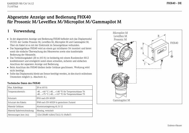
KA00202F/00/C4/14.12 71197764 FHX40 - DE Endress+Hauser Abgesetzte Anzeige und Bedienung FHX40 für Prosonic M/Levelflex M/Micropilot M/Gammapilot M 1 Verwendung In der abgesetzten Anzeige und Bedienung FHX40 befindet sich das Displaymodul VU331 der Geräte Prosonic M, Levelflex M, Micropilot M und Gammapilot M. Über ein Kabel ist es mit der Elektronik im Sensorgehäuse verbunden. Das Separatgehäuse FHX40 wird an einem gut sichtbaren Ort montiert und bietet somit die einfache Überwachung des Messwertes sowie eine komfortable Bedienung der Messstelle. Das Verbindungskabel (20 m (65 ft)) ist beidseitig mit einem Rundstecker M12 konfektioniert und ermöglicht somit einen schnellen, sicheren und einfachen Anschluss der separaten Anzeige und Bedienung. Beim Anschluss des FHX40 bleiben beide Gehäuse geschlossen. Werkzeug wird nicht benötigt. Sollte das Displaymodul direkt am Sensor benötigt werden, ist dies durch müheloses Umstecken möglich (s. Abschnitt 4.). Technische Daten des FHX40 Max. Kabellänge: 20 m (65 ft) Temperaturbereich: -40…+60 °C (-40…+140 °F) für Temperaturklasse T6 -40…+75 °C (-40…+167 °F) für Temperaturklasse T5 Schutzart: IP65 nach EN 60529 Schutzart des Kabels: IP68 nach EN 60529 in gestecktem Zustand Material Gehäuse: Aluminiumlegierung AL Si 12 Material Kabelverschraubung: Messing, vernickelt Abmessungen [mm (in)]: 122x120x80 (4,8x4,72x3,15) (HxBxT) ENDRESS+HAUSER ENDRESS+HAUSER IP 65 IP 65 Micropilot M Levelflex M Prosonic M Gammapilot M FHX40 H B T
-
Upload
anand-naidoo -
Category
Documents
-
view
577 -
download
9
Transcript of Fhx40 technical & operating manual
KA00202F/00/C4/14.12
71197
FHX40 - DE
Endress+Hauser
Abfür
1
In
VU
Üb
Da
som
Bed
Da
kon
An
Bei
nic
Sol
Um
Tech
Max.
Temp
Schut
Schut
Mater
Mater
Abme
FHX40
H
B
T
764
gesetzte Anzeige und Bedienung FHX40 Prosonic M/Levelflex M/Micropilot M/Gammapilot M
Verwendung
der abgesetzten Anzeige und Bedienung FHX40 befindet sich das Displaymodul
331 der Geräte Prosonic M, Levelflex M, Micropilot M und Gammapilot M.
er ein Kabel ist es mit der Elektronik im Sensorgehäuse verbunden.
s Separatgehäuse FHX40 wird an einem gut sichtbaren Ort montiert und bietet
it die einfache Überwachung des Messwertes sowie eine komfortable
ienung der Messstelle.
s Verbindungskabel (20 m (65 ft)) ist beidseitig mit einem Rundstecker M12
fektioniert und ermöglicht somit einen schnellen, sicheren und einfachen
schluss der separaten Anzeige und Bedienung.
m Anschluss des FHX40 bleiben beide Gehäuse geschlossen. Werkzeug wird
ht benötigt.
lte das Displaymodul direkt am Sensor benötigt werden, ist dies durch müheloses
stecken möglich (s. Abschnitt 4.).
nische Daten des FHX40
Kabellänge: 20 m (65 ft)
eraturbereich: -40…+60 °C (-40…+140 °F) für Temperaturklasse T6
-40…+75 °C (-40…+167 °F) für Temperaturklasse T5
zart: IP65 nach EN 60529
zart des Kabels: IP68 nach EN 60529 in gestecktem Zustand
ial Gehäuse: Aluminiumlegierung AL Si 12
ial Kabelverschraubung: Messing, vernickelt
ssungen [mm (in)]: 122x120x80 (4,8x4,72x3,15) (HxBxT)
ENDRESS+HAUSER
ENDRESS+HAUSER
IP 65IP 65
Order Code:Ser.-No.:
Order Code:Ser.-No.:
MessbereichMeasuring range
MessbereichMeasuring rangeU 16...36 V DC
4...20 mA
U 16...36 V DC4...20 mA
max. 20 m
max. 20 m
Made in
Germ
any
M
aulb
urg
Made in
Germ
any
M
aulb
urg
T>70°C :
A
t >85°C
T>70°C :
A
t >85°C
Micropilot MLevelflex MProsonic M
Gammapilot M
Endress+Hauser
FHX40 - DE
2
Siche
Das S
Der d
essgerät und an das Separatgehäuse FHX40
nktionsbereit. Um an die Bedienung zu gelangen,
paratgehäuses lösen und Deckel aufklappen.
HX40 die Kurzanleitungen zu den Geräten
t M und Gammapilot M. Verwenden Sie zur
ltige Kurzanleitung.
(o
mm
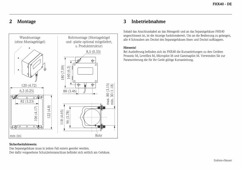
Montage
rheitshinweis:
eparatgehäuse muss in jedem Fall extern geerdet werden.
afür vorgesehene Schutzleiteranschluss befindet sich seitlich am Gehäuse.
3 Inbetriebnahme
Sobald das Anschlusskabel an das M
angeschlossen ist, ist die Anzeige fu
alle 4 Schrauben am Deckel des Se
Hinweis!
Bei Auslieferung befinden sich im F
Prosonic M, Levelflex M, Micropilo
Parametrierung die für Ihr Gerät gü
82 (3.23)
6,3 (0.25)
10
6 (
4.1
7)
12
2 (
4.8
)
120 (4.72)
max
. 8
0 (
3.1
5)
min
. 3
0 (
1.1
8)
96
(3
.78
)
88 (3.46)
16
0 (
6.3
)
8,5 (0.33)
11
8 (
4.6
5)
18
0 (
7.0
9)
Rohr
Wandmontagehne Montagebügel)
Rohrmontage (Montagebügelund -platte optional mitgeliefert,
s. Produktstruktur)
(in)
Endress+Hauser
FHX40 - DE
4
In ein
einzu
Anten
Vorge
1. A
2. A
H
3. D
4. S
e
5. A
Soll di
Arbeit
Hinw
Um d
Drehm
ENDRESS+HAUSER
ENDRESS+HAUSER
1 2
3
4
5
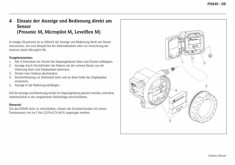
Einsatz der Anzeige und Bedienung direkt am
Sensor
(Prosonic M, Micropilot M, Levelflex M)
igen Situationen ist es hilfreich die Anzeige und Bedienung direkt am Sensor
setzen, wie zum Beispiel bei der Inbetriebnahme oder zur Ausrichtung der
ne (beim Micropilot M).
hensweise:
lle 4 Schrauben am Deckel des Separatgehäuses lösen und Deckel aufklappen.
nzeige durch Hochdrücken des Hakens (an der unteren Kante) aus der
alterung lösen und Displaykabel abstecken.
eckel vom Gehäuse abschrauben.
teckverbindung zur Elektronik lösen und an diese Stelle das Displaykabel
instecken.
nzeige in die Halterung einhängen.
e Anzeige und Bedienung wieder im Separatgehäuse platziert werden, sind diese
sschritte in der umgekehrten Reihenfolge durchzuführen.
eis!
as FHX40 dicht zu verschließen, müssen die Deckelschrauben mit einem
oment von 4±1 Nm (2,95±0,74 lbf ft) angezogen werden.
ENDRESS+HAUSER
MICROPILOT II
ENDRESS+HAUSER
MICROPILOT II
IP 65IP 65
Order Code:Ser.-No.:
Order Code:Ser.-No.:
MessbereichMeasuring range
MessbereichMeasuring rangeU 16...36 V DC
4...20 mA
U 16...36 V DC4...20 mA
max. 20 m
max. 20 m
Made in
Germ
any
M
aulb
urg
T>70°C :
A
t >85°C
T>70°C :
A
t >85°C
KA00202F/00/C4/14.12
71197
FHX40 - DE
Endress+Hauser
5
Verwe
vorge
Hinw
Für di
die ab
den.
mentation
a IIC T6/T5
e 1 Ex ia IIC T6/T5
I Div. 1 Gr. A-D, Zone 0
iv. 1 Gr. A-D, Zone 0
FHX4
764
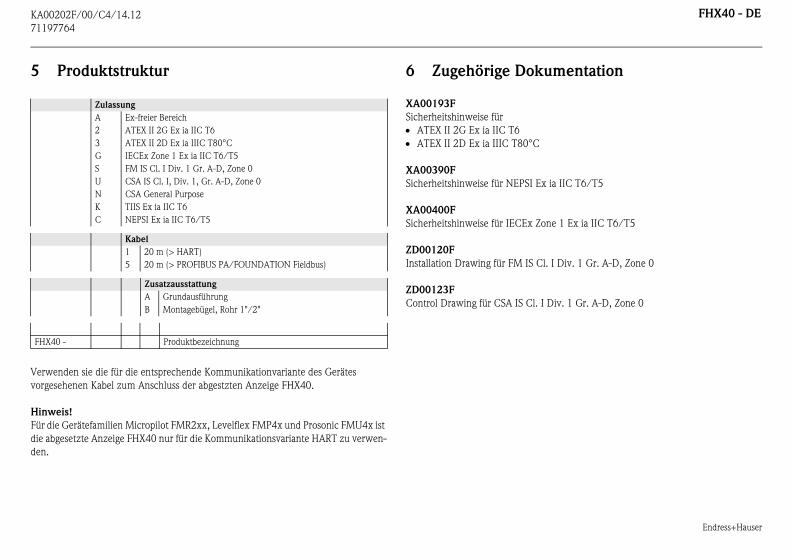
Produktstruktur
nden sie die für die entsprechende Kommunikationvariante des Gerätes
sehenen Kabel zum Anschluss der abgestzten Anzeige FHX40.
eis!
e Gerätefamilien Micropilot FMR2xx, Levelflex FMP4x und Prosonic FMU4x ist
gesetzte Anzeige FHX40 nur für die Kommunikationsvariante HART zu verwen-
6 Zugehörige Doku
XA00193F
Sicherheitshinweise für
ATEX II 2G Ex ia IIC T6
ATEX II 2D Ex ia IIIC T80°C
XA00390F
Sicherheitshinweise für NEPSI Ex i
XA00400F
Sicherheitshinweise für IECEx Zon
ZD00120F
Installation Drawing für FM IS Cl.
ZD00123F
Control Drawing für CSA IS Cl. I D
Zulassung
A Ex-freier Bereich
2 ATEX II 2G Ex ia IIC T6
3 ATEX II 2D Ex ia IIIC T80°C
G IECEx Zone 1 Ex ia IIC T6/T5
S FM IS Cl. I Div. 1 Gr. A-D, Zone 0
U CSA IS Cl. I, Div. 1, Gr. A-D, Zone 0
N CSA General Purpose
K TIIS Ex ia IIC T6
C NEPSI Ex ia IIC T6/T5
Kabel
1 20 m (> HART)
5 20 m (> PROFIBUS PA/FOUNDATION Fieldbus)
Zusatzausstattung
A Grundausführung
B Montagebügel, Rohr 1"/2"
0 - Produktbezeichnung
KA00202F/00/C4/14.12
71197
FHX40 - EN
Endress+Hauser
Remfor
1
Th
ins
it is
Th
ena
dis
Th
sid
For
req
Sho
ma
Tech
Max.
Temp
Ingres
Ingres
Mater
Mater
Dime
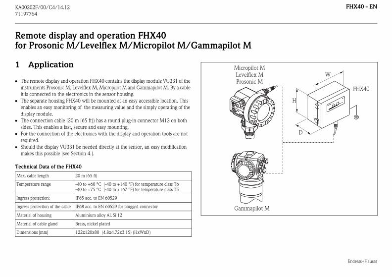
FHX40
H
W
D
764
ote display and operation FHX40 Prosonic M/Levelflex M/Micropilot M/Gammapilot M
Application
e remote display and operation FHX40 contains the display module VU331 of the
truments Prosonic M, Levelflex M, Micropilot M and Gammapilot M. By a cable
connected to the electronics in the sensor housing.
e separate housing FHX40 will be mounted at an easy accessible location. This
bles an easy monitoring of the measuring value and the simply operating of the
play module.
e connection cable (20 m (65 ft)) has a round plug-in connector M12 on both
es. This enables a fast, secure and easy mounting.
the connection of the electronics with the display and operation tools are not
uired.
uld the display VU331 be needed directly at the sensor, an easy modification
kes this possible (see Section 4.).
nical Data of the FHX40
cable length 20 m (65 ft)
erature range -40 to +60 °C (-40 to +140 °F) for temperature class T6
-40 to +75 °C (-40 to +167 °F) for temperature class T5
s protection: IP65 acc. to EN 60529
s protection of the cable IP68 acc. to EN 60529 for plugged connector
ial of housing Aluminium alloy AL Si 12
ial of cable gland Brass, nickel plated
nsions [mm] 122x120x80 (4.8x4.72x3.15) (HxWxD)
ENDRESS+HAUSER
ENDRESS+HAUSER
IP 65IP 65
Order Code:Ser.-No.:
Order Code:Ser.-No.:
MessbereichMeasuring range
MessbereichMeasuring rangeU 16...36 V DC
4...20 mA
U 16...36 V DC4...20 mA
max. 20 m
max. 20 m
Made in
Germ
any
M
aulb
urg
Made in
Germ
any
M
aulb
urg
T>70°C :
A
t >85°C
T>70°C :
A
t >85°C
Micropilot MLevelflex MProsonic M
Gammapilot M
Endress+Hauser
FHX40 - EN
2
Safety
It is v
the pr
s the instrument is connected with the separate
4 screws at the cover of the separate housing and
e instruments Prosonic M, Levelflex M,
re located in the FHX40. For commissioning, use
rument.
mm
(with
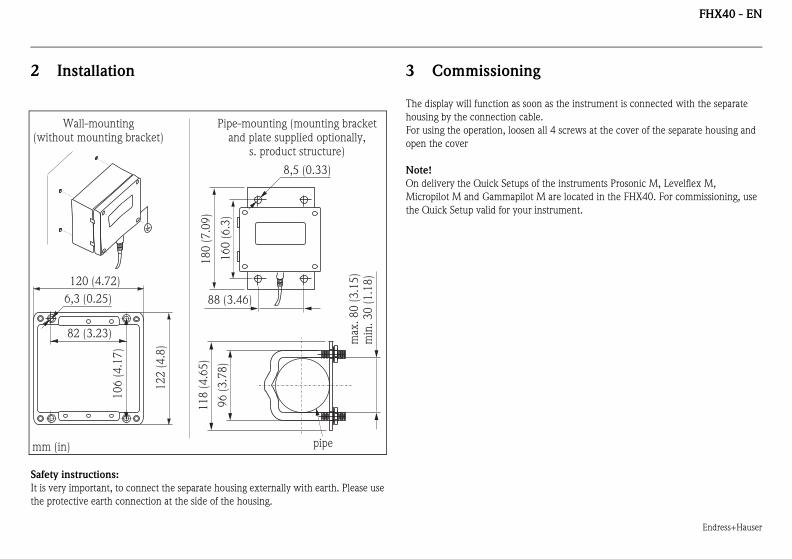
Installation
instructions:
ery important, to connect the separate housing externally with earth. Please use
otective earth connection at the side of the housing.
3 Commissioning
The display will function as soon a
housing by the connection cable.
For using the operation, loosen all
open the cover
Note!
On delivery the Quick Setups of th
Micropilot M and Gammapilot M a
the Quick Setup valid for your inst
82 (3.23)
6,3 (0.25)
10
6 (
4.1
7)
12
2 (
4.8
)
120 (4.72)
max
. 8
0 (
3.1
5)
min
. 3
0 (
1.1
8)
96
(3
.78
)
88 (3.46)
16
0 (
6.3
)
8,5 (0.33)
11
8 (
4.6
5)
18
0 (
7.0
9)
(in)
Wall-mountingout mounting bracket)
Pipe-mounting (mounting bracketand plate supplied optionally,
s. product structure)
pipe
Endress+Hauser
FHX40 - EN
4
In som
espec
Proce
1. L
2. T
a
3. U
4. D
5. L
If the
above
Note
Leak-
tighte
ENDRESS+HAUSER
ENDRESS+HAUSER
1 2
3
4
5
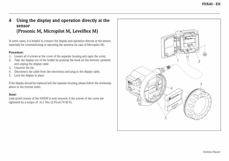
Using the display and operation directly at the
sensor
(Prosonic M, Micropilot M, Levelflex M)
e cases, it is helpful to connect the display and operation directly at the sensor,
ially for commissioning or adjusting the antenna (in case of Micropilot M).
dure:
oosen all 4 screws at the cover of the separate housing and open the cover.
ake the display out of the holder by pushing the hook (at the bottom) upwards
nd unplug the display cable
nscrew the lid.
isconnect the cable from the electronics and plug in the display cable.
ock the display in place.
display should be replaced into the separate housing, please follow the worksteps
in the reverse order.
!
proof closure of the FHX40 is only ensured, if the screws of the cover are
ned by a torque of 4±1 Nm (2.95±0.74 lbf ft).
ENDRESS+HAUSER
MICROPILOT II
ENDRESS+HAUSER
MICROPILOT II
IP 65IP 65
Order Code:Ser.-No.:
Order Code:Ser.-No.:
MessbereichMeasuring range
MessbereichMeasuring rangeU 16...36 V DC
4...20 mA
U 16...36 V DC4...20 mA
max. 20 m
max. 20 m
Made in
Germ
any
M
aulb
urg
T>70°C :
A
t >85°C
T>70°C :
A
t >85°C
KA00202F/00/C4/14.12
71197
FHX40 - EN
Endress+Hauser
5
For co
comm
Note
For th
the re
entation
IIC T6/T5
1 Ex ia IIC T6/T5
I Div. 1 Gr. A-D, zone 0
iv. 1 Gr. A-D, zone 0
FHX4
764
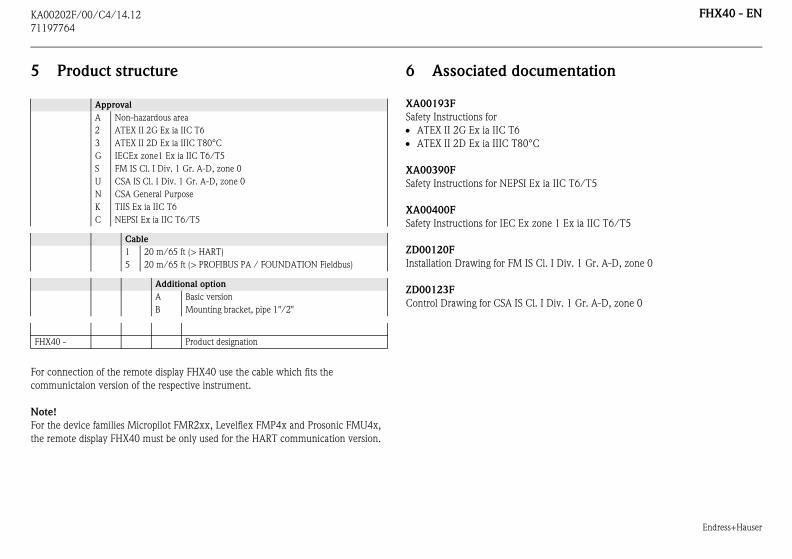
Product structure
nnection of the remote display FHX40 use the cable which fits the
unictaion version of the respective instrument.
!
e device families Micropilot FMR2xx, Levelflex FMP4x and Prosonic FMU4x,
mote display FHX40 must be only used for the HART communication version.
6 Associated docum
XA00193F
Safety Instructions for
ATEX II 2G Ex ia IIC T6
ATEX II 2D Ex ia IIIC T80°C
XA00390F
Safety Instructions for NEPSI Ex ia
XA00400F
Safety Instructions for IEC Ex zone
ZD00120F
Installation Drawing for FM IS Cl.
ZD00123F
Control Drawing for CSA IS Cl. I D
Approval
A Non-hazardous area
2 ATEX II 2G Ex ia IIC T6
3 ATEX II 2D Ex ia IIIC T80°C
G IECEx zone1 Ex ia IIC T6/T5
S FM IS Cl. I Div. 1 Gr. A-D, zone 0
U CSA IS Cl. I Div. 1 Gr. A-D, zone 0
N CSA General Purpose
K TIIS Ex ia IIC T6
C NEPSI Ex ia IIC T6/T5
Cable
1 20 m/65 ft (> HART)
5 20 m/65 ft (> PROFIBUS PA / FOUNDATION Fieldbus)
Additional option
A Basic version
B Mounting bracket, pipe 1"/2"
0 - Product designation
KA00202F/00/C4/14.12
71197
FHX40 - FR
Endress+Hauser
Affpou
1
L'a
app
d'u
Le
sur
con
Le
M1
Les
Au
Si l
réa
Carac
Longu
Gamm
Protec
Protec
Matér
Matér
Dime
FHX40
L
H
P
764
icheur-configurateur FHX40r Prosonic M/Levelflex M/Micropilot M/Gammapilot M
Utilisation
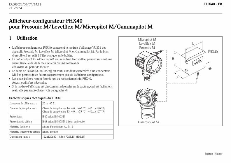
fficheur-configurateur FHX40 comprend le module d'affichage VU331 des
areils Prosonic M, Levelflex M, Micropilot M et Gammapilot M. Par le biais
n câble il est relié à l'électronique en le boîtier.
boîtier séparé FHX40 est monté en un endroit bien visible, permettant ainsi une
veillance aisée de la mesure ainsi qu'une commande
viviale du point de mesure.
câble de liaison (20 m (65 ft)) est muni aux deux extrémités d'un connecteur
2 et permet de ce fait un raccordement aisé de l'afficheur-configurateur.
deux boîtiers restent fermés lors du raccordement du FHX40.
cun outil n'est nécessaire.
e module d'affichage est directement nécessaire sur le capteur, ceci est facilement
lisable par embrochage (voir paragraphe 4).
téristiques techniques du FHX40
eur de câble max. : 20 m (65 ft)
e de température : Classe de température T6: -40…+60 °C (-40…+140 °F)
Classe de température T5: -40…+75 °C (-40…+167 °F)
tion : IP65 selon EN 60529
tion du câble : IP68 selon EN 60529 à l'état embroché
iau (boîtier) : alliage d'aluminium AL Si 12
iau (raccord de câble): laiton, anodisé
nsions [mm] : 122x120x80 (4.8x4.72x3.15) (HxLxP)
ENDRESS+HAUSER
ENDRESS+HAUSER
IP 65IP 65
Order Code:Ser.-No.:
Order Code:Ser.-No.:
MessbereichMeasuring range
MessbereichMeasuring rangeU 16...36 V DC
4...20 mA
U 16...36 V DC4...20 mA
max. 20 m
max. 20 m
Made in
Germ
any
M
aulb
urg
T>70°C :
A
t >85°C
T>70°C :
A
t >85°C
Micropilot MLevelflex MProsonic M
Gammapilot M
Endress+Hauser
FHX40 - FR
2
Cons
Le bo
Le câb
est relié à l'appareil de mesure et au
prêt à fonctionner. Pour accéder au configurateur,
ouvercle du boîtier séparé et de rabattre ce dernier.
les mises en service condensées des appareils
t M et Gammapilot M. Pour le paramétrage,
mm
(sa
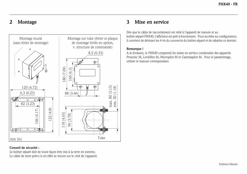
Montage
eil de sécurité :
îtier séparé doit de toute façon être mis à la terre en externe.
le de terre prévu à cet effet se trouve sur le côté de l'appareil.
3 Mise en service
Dès que le câble de raccordement
boîtier séparé FHX40, l'afficheur est
il convient de dévisser les 4 vis du c
Remarque !
A la livraison, le FHX40 comprend
Prosonic M, Levelflex M, Micropilo
utiliser le manuel correspondant.
82 (3.23)
6,3 (0.25)
10
6 (
4.1
7)
12
2 (
4.8
)
120 (4.72)
max
. 8
0 (
3.1
5)
min
. 3
0 (
1.1
8)
96
(3
.78
)
88 (3.46)
16
0 (
6.3
)
8,5 (0.33)
11
8 (
4.6
5)
18
0 (
7.0
9)
(in)
Montage muralns étrier de montage)
Montage sur tube (étrier et plaquede montage livrés en option,v. structure de commande)
Tube
Endress+Hauser
FHX40 - FR
4
Dans
direct
de l'an
Procé
1. D
2. E
s
3. D
4. D
l'
5. A
Si l'aff
ces ét
Rema
Pour g
coupl
ENDRESS+HAUSER
ENDRESS+HAUSER
1 2
3
4
5
Utilisation de l'afficheur-configurateur
directement sur le capteur
(Prosonic M, Micropilot M, Gammapilot M)
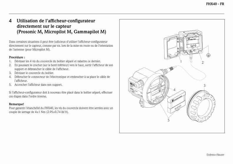
certaines situations il peut être judicieux d'utiliser l'afficheur-configurateur
ement sur le capteur, comme par ex. lors de la mise en route ou de l'orientation
tenne (pour Micropilot M).
dure :
évisser les 4 vis du couvercle du boîtier séparé et rabattre ce dernier.
n poussant le crochet (sur le bord inférieur) vers le haut, sortir l'afficheur de son
upport et débrancher le câble de l'afficheur.
évisser le couvercle du boîtier.
ébrocher le connecteur de l'électronique et embrocher à sa place le câble de
afficheur.
ccrocher l'afficheur dans son support.
icheur-configurateur doit à nouveau être placé dans le boîtier séparé, effectuer
apes dans l'ordre inverse.
rque!
arantir l'étanchéité du FHX40, les vis du couvercle doivent être serrées avec un
e de serrage de 4±1 Nm (2.95±0.74 lbf ft).
ENDRESS+HAUSER
MICROPILOT II
ENDRESS+HAUSER
MICROPILOT II
IP 65IP 65
Order Code:Ser.-No.:
Order Code:Ser.-No.:
MessbereichMeasuring range
MessbereichMeasuring rangeU 16...36 V DC
4...20 mA
U 16...36 V DC4...20 mA
max. 20 m
max. 20 m
Made in
Germ
any
M
aulb
urg
T>70°C :
A
t >85°C
T>70°C :
A
t >85°C
KA00202F/00/C4/14.12
71197
FHX40 - FR
Endress+Hauser
5
Utilise
raccor
Rema
Conce
FMU4
comm
orrespondante
ia IIC T6/T5
ne1 Ex ia IIC T6/T5
l. I Div. 1 Gr. A-D, zone 0
Div. 1 Gr. A-D, zone 0
FHX4
764
Structure de commande
r, pour la variante communication de l'appareil, les câbles prévus pour le
dement de l'afficheur déporté FHX40.
rque!
rnant les familles d'appareils Micropilot FMR2xx, Levelflex FMP4x et Prosonic
x, l’afficheur séparé FHX40 doit être utilisé uniquement pour la version avec
unication HART.
6 Documentation c
XA00193F
Conseils de sécurité pour
ATEX II 2G Ex ia IIC T6
ATEX II 2D Ex ia IIIC T80°C
XA00390F
Conseils de sécurité pour NEPSI Ex
XA00400F
Conseils de sécurité pour IECEx zo
ZD00120F
Installation Drawing pour FM IS C
ZD00123F
Control Drawing pour CSA IS Cl. I
Agrément
A zone non Ex
2 ATEX II 2G Ex ia IIC T6
3 ATEX II 2D Ex ia IIIC T80°C
G IECEx zone 1 Ex ia IIC T6/T5
S FM IS Cl. I Div. 1 Gr.s A-D, zone 0
U CSA IS Cl. I Div. 1 Gr. A-D, zone 0
N CSA General Purpose
K TIIS Ex ia IIC T6
C NEPSI Ex ia IIC T6/T5
Longueur de câble
1 20 m (> HART)
5 20 m (> PROFIBUS PA/FOUNDATION Fieldbus)
Option supplémentaire
A version standard
B étrier de montage, tube 1"/2"
0 - Référence complète
KA00202F/00/C4/14.12
71197
FHX40 - IT
Endress+Hauser
Disper
1
Il d
Pro
Il d
qua
ver
20m
rap
Per
Se
col
Dati t
Lungh
Camp
Protez
Protez
Mater
Mater
Dime
FHX40
W
H
D
764
play remoto FHX40 Prosonic M / Levelflex M / Micropilot M/Gammapilot M
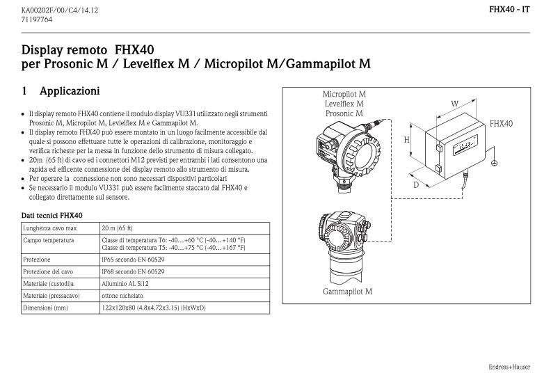
Applicazioni
isplay remoto FHX40 contiene il modulo display VU331utilizzato negli strumenti
sonic M, Micropilot M, Levlelflex M e Gammapilot M.
isplay remoto FHX40 può essere montato in un luogo facilmente accessibile dal
le si possono effettuare tutte le operazioni di calibrazione, monitoraggio e
ifica richeste per la messa in funzione dello strumento di misura collegato.
(65 ft) di cavo ed i connettori M12 previsti per entrambi i lati consentono una
ida ed efficente connessione del display remoto allo strumento di misura.
operare la connessione non sono necessari dispositivi particolari
necessario il modulo VU331 può essere facilmente staccato dal FHX40 e
legato direttamente sul sensore.
ecnici FHX40
ezza cavo max 20 m (65 ft)
o temperatura Classe di temperatura T6: -40…+60 °C (-40…+140 °F)
Classe di temperatura T5: -40…+75 °C (-40…+167 °F)
ione IP65 secondo EN 60529
ione del cavo IP68 secondo EN 60529
iale (custodi)a Alluminio AL Si12
iale (pressacavo) ottone nichelato
nsioni (mm) 122x120x80 (4.8x4.72x3.15) (HxWxD)
ENDRESS+HAUSER
ENDRESS+HAUSER
IP 65IP 65
Order Code:Ser.-No.:
Order Code:Ser.-No.:
MessbereichMeasuring range
MessbereichMeasuring rangeU 16...36 V DC
4...20 mA
U 16...36 V DC4...20 mA
max. 20 m
max. 20 m
Made in
Germ
any
M
aulb
urg
Made in
Germ
any
M
aulb
urg
T>70°C :
A
t >85°C
T>70°C :
A
t >85°C
Micropilot MLevelflex MProsonic M
Gammapilot M
Endress+Hauser
FHX40 - IT
2
Istruz
E' imp
Per la
strumento di misura ed entrerà in
a la connessione.
ione, aprire il coperchio svitando le quattro viti di
dicazioni brevi per la programmazione dei
, Micropilot M e Gammapilot M utilizzate quella
mm
(sen
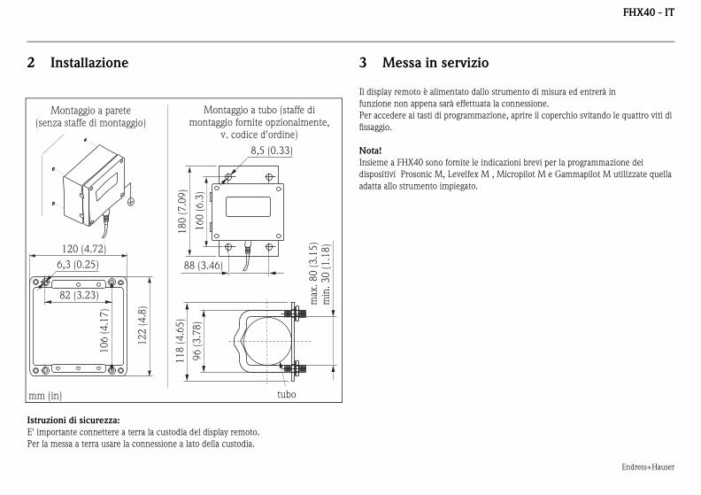
Installazione
ioni di sicurezza:
ortante connettere a terra la custodia del display remoto.
messa a terra usare la connessione a lato della custodia.
3 Messa in servizio
Il display remoto è alimentato dallo
funzione non appena sarà effettuat
Per accedere ai tasti di programmaz
fissaggio.
Nota!
Insieme a FHX40 sono fornite le in
dispositivi Prosonic M, Levelfex M
adatta allo strumento impiegato.
82 (3.23)
6,3 (0.25)
10
6 (
4.1
7)
12
2 (
4.8
)
120 (4.72)
max
. 8
0 (
3.1
5)
min
. 3
0 (
1.1
8)
96
(3
.78
)
88 (3.46)
16
0 (
6.3
)
8,5 (0.33)
11
8 (
4.6
5)
18
0 (
7.0
9)
(in)
Montaggio a pareteza staffe di montaggio)
Montaggio a tubo (staffe dimontaggio fornite opzionalmente,
v. codice d'ordine)
tubo
Endress+Hauser
FHX40 - IT
4
In alc
l'orien
1. a
2. e
c
3. s
4. s
5. m
Per ri
Nota!
La cla
strette
ENDRESS+HAUSER
ENDRESS+HAUSER
1 2
3
4
5
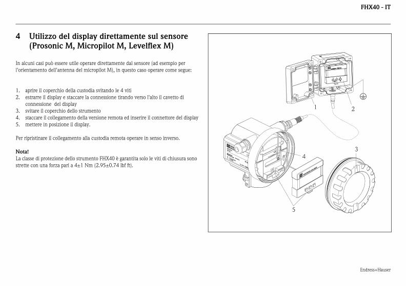
Utilizzo del display direttamente sul sensore
(Prosonic M, Micropilot M, Levelflex M)
uni casi può essere utile operare direttamente dal sensore (ad esempio per
tamento dell'antenna del micropilot M), in questo caso operare come segue:
prire il coperchio della custodia svitando le 4 viti
strarre il display e staccare la connessione tirando verso l'alto il cavetto di
onnessione del display
vitare il coperchio dello strumento
taccare il collegamento della versione remota ed inserire il connettore del display
ettere in posizione il display.
pristinare il collegamento alla custodia remota operare in senso inverso.
sse di protezione dello strumento FHX40 è garantita solo le viti di chiusura sono
con una forza pari a 4±1 Nm (2.95±0.74 lbf ft).
ENDRESS+HAUSER
MICROPILOT II
ENDRESS+HAUSER
MICROPILOT II
IP 65IP 65
Order Code:Ser.-No.:
Order Code:Ser.-No.:
MessbereichMeasuring range
MessbereichMeasuring rangeU 16...36 V DC
4...20 mA
U 16...36 V DC4...20 mA
max. 20 m
max. 20 m
Made in
Germ
any
M
aulb
urg
T>70°C :
A
t >85°C
T>70°C :
A
t >85°C
ww.endress.com/worldwide
FHX40 - ITKA00202F/00/C4/14.12
71197
5
Per il
rispet
Nota!
Per le
il disp
one H
a IIC T6/T5
e 1 Ex ia IIC T6/T5
v. 1 Gr. A-D, zona 0
1 Gr. A-D, zona 0
FHX4
w
764
71197764
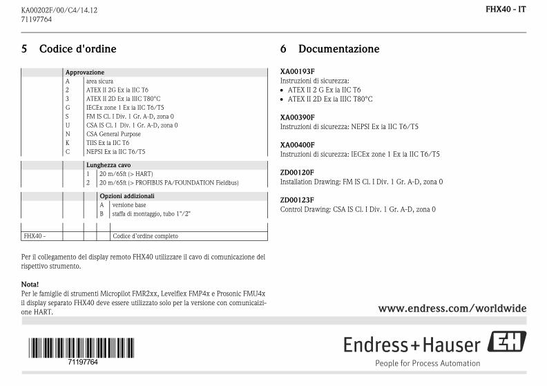
Codice d'ordine
collegamento del display remoto FHX40 utilizzare il cavo di comunicazione del
tivo strumento.
famiglie di strumenti Micropilot FMR2xx, Levelflex FMP4x e Prosonic FMU4x
lay separato FHX40 deve essere utilizzato solo per la versione con comunicaizi-
ART.
6 Documentazione
XA00193F
Instruzioni di sicurezza:
ATEX II 2 G Ex ia IIC T6
ATEX II 2D Ex ia IIIC T80°C
XA00390F
Instruzioni di sicurezza: NEPSI Ex i
XA00400F
Instruzioni di sicurezza: IECEx zon
ZD00120F
Installation Drawing: FM IS Cl. I Di
ZD00123F
Control Drawing: CSA IS Cl. I Div.
Approvazione
A area sicura
2 ATEX II 2G Ex ia IIC T6
3 ATEX II 2D Ex ia IIIC T80°C
G IECEx zone 1 Ex ia IIC T6/T5
S FM IS Cl. I Div. 1 Gr. A-D, zona 0
U CSA IS Cl. I Div. 1 Gr. A-D, zona 0
N CSA General Purpose
K TIIS Ex ia IIC T6
C NEPSI Ex ia IIC T6/T5
Lunghezza cavo
1 20 m/65ft (> HART)
2 20 m/65ft (> PROFIBUS PA/FOUNDATION Fieldbus)
Opzioni addizionali
A versione base
B staffa di montaggio, tubo 1"/2"
0 - Codice d’ordine completo