Forschungszentrum Karlsruhe Technik und Umwelt IRS /FzK W.M.SchikorrEUROTRANS WP1.5 Safety Meeting :...
22
Forschungszentrum Karlsruhe Technik und Umwelt IRS /FzK W.M.Schikorr EUROTRANS WP1.5 Safety Meeting : Lyon, Oct 11-12. 2006 1 Temperature Limits for XT- Temperature Limits for XT- ADS Clad Material T-91 ADS Clad Material T-91 M. Schikorr D. Struwe (FzK) M. Schikorr D. Struwe (FzK) EUROTRANS: DM1 WP1.5 : “Safety” Lyon , 10-11 October 2006
-
date post
18-Dec-2015 -
Category
Documents
-
view
212 -
download
0
Transcript of Forschungszentrum Karlsruhe Technik und Umwelt IRS /FzK W.M.SchikorrEUROTRANS WP1.5 Safety Meeting :...
Forschungszentrum KarlsruheTechnik und Umwelt
IRS /FzK W.M.SchikorrEUROTRANS WP1.5 Safety Meeting : Lyon, Oct 11-12. 2006 1
Temperature Limits for XT-ADS Temperature Limits for XT-ADS Clad Material T-91Clad Material T-91
M. Schikorr D. Struwe (FzK)M. Schikorr D. Struwe (FzK)
EUROTRANS: DM1 WP1.5 : “Safety”
Lyon , 10-11 October 2006
Forschungszentrum KarlsruheTechnik und Umwelt
IRS /FzK W.M.SchikorrEUROTRANS WP1.5 Safety Meeting : Lyon, Oct 11-12. 2006 2
1. Lower Temperature Limits of T-91 Clad Material under Nominal Conditions
2. Upper Temperature Limits of T-91 Clad Material under Nominal Conditions
3. Temperature Limits of T-91 Clad Material under Transient Conditions
Topics:
Forschungszentrum KarlsruheTechnik und Umwelt
IRS /FzK W.M.SchikorrEUROTRANS WP1.5 Safety Meeting : Lyon, Oct 11-12. 2006 3
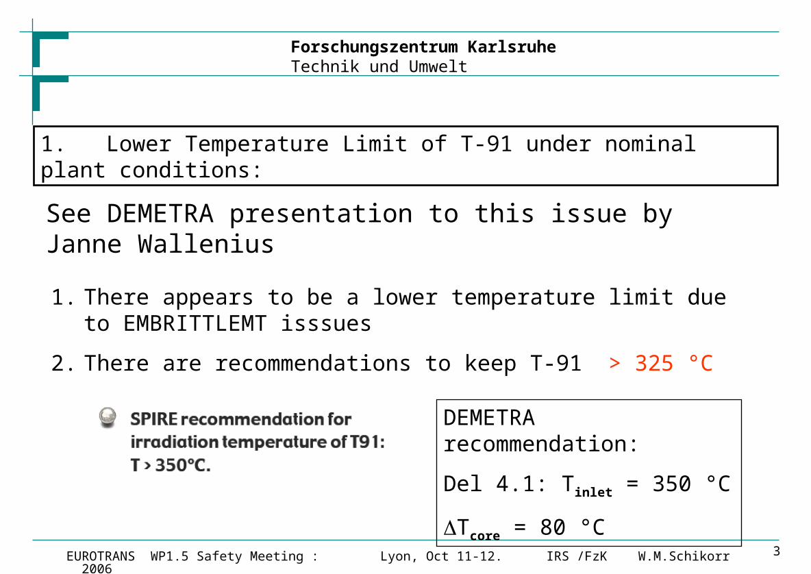
1. There appears to be a lower temperature limit due to EMBRITTLEMT isssues
2. There are recommendations to keep T-91 > 325 °C
1. Lower Temperature Limit of T-91 under nominal plant conditions:
See DEMETRA presentation to this issue by Janne Wallenius
DEMETRA recommendation:
Del 4.1: Tinlet = 350 °C
Tcore = 80 °C

Forschungszentrum KarlsruheTechnik und Umwelt
IRS /FzK W.M.SchikorrEUROTRANS WP1.5 Safety Meeting : Lyon, Oct 11-12. 2006 4
1. To avoid CORROSION of T-91 one should keep the upper clad temperature < 500 °C
2. FeAl alloy COATING by GESA treatment will improve corrosion resistance and the upper temperature limit increased to about 550°C (L. Mansani).
3. No „coating“ requires that the nominal maximum cladding temperature of the peak pin should be below ~ 490 °C to provide margin to account for hot-spot analyses results.
2. Upper Temperature Limit of T-91 under nominal plant conditions:
Forschungszentrum KarlsruheTechnik und Umwelt
IRS /FzK W.M.SchikorrEUROTRANS WP1.5 Safety Meeting : Lyon, Oct 11-12. 2006 5
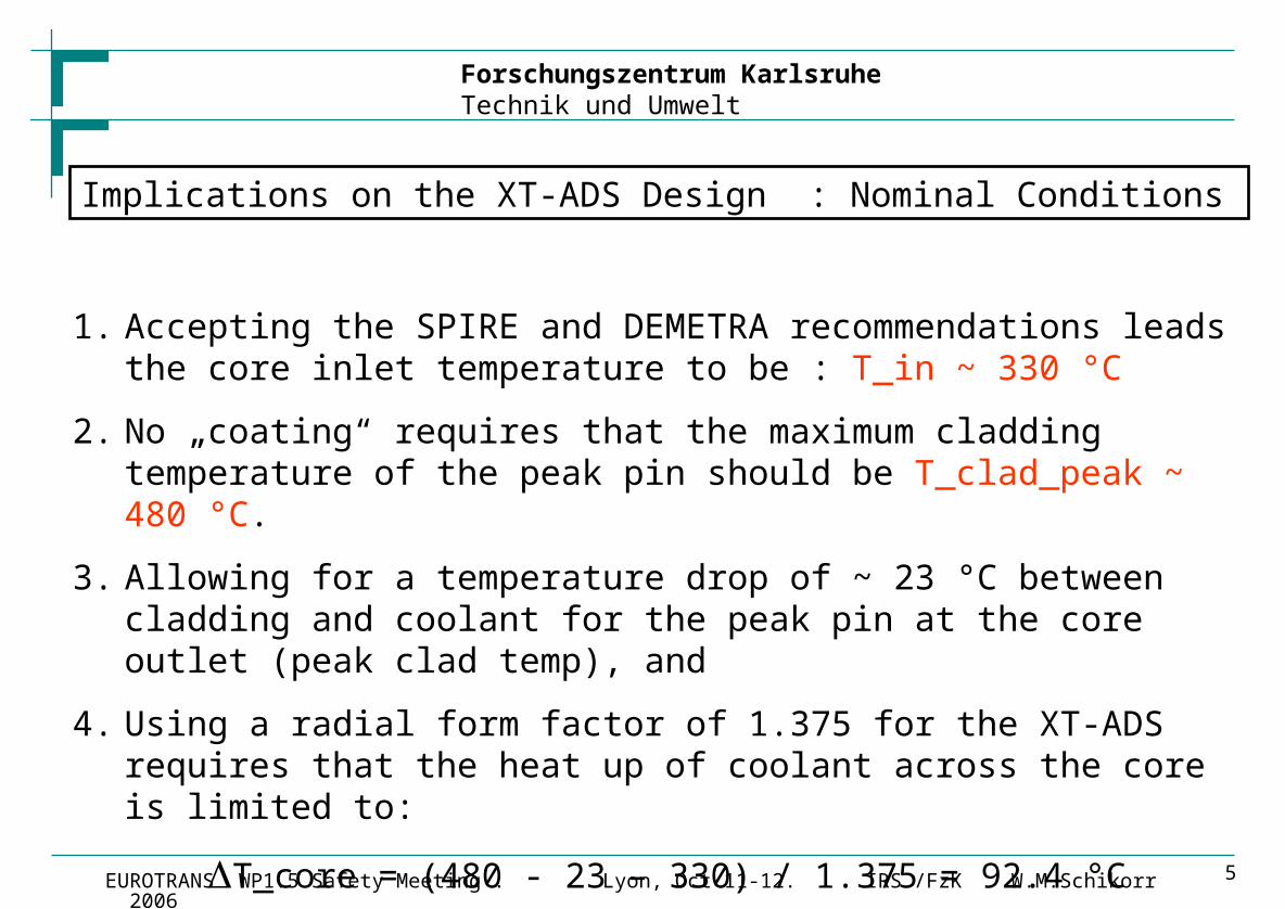
1. Accepting the SPIRE and DEMETRA recommendations leads the core inlet temperature to be : T_in ~ 330 °C
2. No „coating“ requires that the maximum cladding temperature of the peak pin should be T_clad_peak ~ 480 °C.
3. Allowing for a temperature drop of ~ 23 °C between cladding and coolant for the peak pin at the core outlet (peak clad temp), and
4. Using a radial form factor of 1.375 for the XT-ADS requires that the heat up of coolant across the core is limited to:
T_core = (480 - 23 – 330) / 1.375 = 92.4 °C
We have select : T_core = 90 °C
Implications on the XT-ADS Design : Nominal Conditions
Forschungszentrum KarlsruheTechnik und Umwelt
IRS /FzK W.M.SchikorrEUROTRANS WP1.5 Safety Meeting : Lyon, Oct 11-12. 2006 6
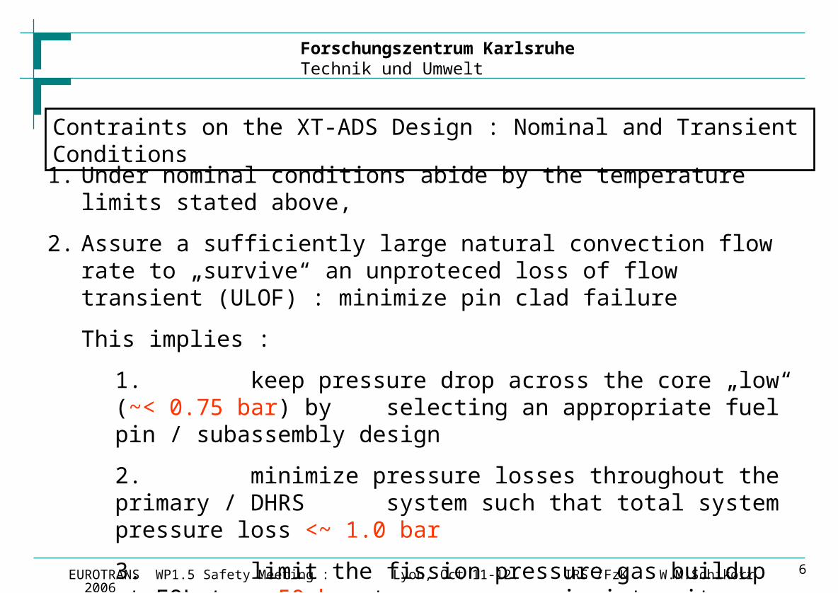
1. Under nominal conditions abide by the temperature limits stated above,
2. Assure a sufficiently large natural convection flow rate to „survive“ an unproteced loss of flow transient (ULOF) : minimize pin clad failure
This implies :
1. keep pressure drop across the core „low“ (~< 0.75 bar) by selecting an appropriate fuel pin / subassembly design
2. minimize pressure losses throughout the primary / DHRS system such that total system pressure loss <~ 1.0 bar
3. limit the fission pressure gas buildup at EOL to ~ 50 bar to assure pin integrity under ULOF conditions. This implies designing an appropriate fission gas plenum volume.
Contraints on the XT-ADS Design : Nominal and Transient Conditions
Forschungszentrum KarlsruheTechnik und Umwelt
IRS /FzK W.M.SchikorrEUROTRANS WP1.5 Safety Meeting : Lyon, Oct 11-12. 2006 7
1. There are several different modes of pin cladding failure.
2. One of the most important is CLAD CREEP failure.
3. Recent experimental data of unirradiated T-91 material by CIEMAT yielded creep data which indicate that particular attention needs to be paid to this potential clad failure mode under all transient conditions leading to cladding temperatures higher than > 800 °C. This in particular applies to ULOF at EOL conditions when the fuel pins are pressurized by the accumulated released fission gas .
4. For T-91 the clad failure limit is no longer ~ 1000 °C (as we have asssumed in a somewhat generous manner during the PDS-XADS safety study), but it is now in the range ~ 850 °C.
Pin/Cladding Failure Conditions under Transient Conditions (1/2) :
Forschungszentrum KarlsruheTechnik und Umwelt
IRS /FzK W.M.SchikorrEUROTRANS WP1.5 Safety Meeting : Lyon, Oct 11-12. 2006 8
5. The failure time of the cladding due to clad creep is dependent on 3 major parameters, namely:
1. Type of cladding material selected,
2. Hoop_Stress, essentially determined by
a. the fission gas pressure Pgas, and
b. the geometry of the pin design, namely outer pin diameter and cladding thickness,
3. The temperature of the cladding material.
Pin/Cladding Failure Conditions under Transient Conditions (2/2):
Forschungszentrum KarlsruheTechnik und Umwelt
IRS /FzK W.M.SchikorrEUROTRANS WP1.5 Safety Meeting : Lyon, Oct 11-12. 2006 9
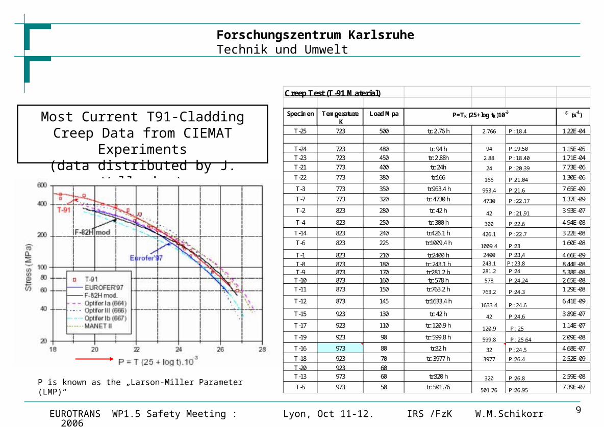
Most Current T91-Cladding Creep Data from CIEMAT Experiments
(data distributed by J. Wallenius)
Creep Test (T-91 Material)
Specimen Temperature K
Load Mpa e (s -1)
T-25 723 500 tr: 2.76 h 2.766 P: 18.4 1.22E-04
T-24 723 480 tr: 94 h 94 P:19.50 1.15E-05
T-23 723 450 tr: 2.88h 2.88 P: 18.40 1.71E-04
T-21 773 400 tr: 24h 24 P: 20.39 7.73E-06
T-22 773 380 tr:166 166 P:21.04 1.30E-06
T-3 773 350 tr:953.4 h 953.4 P:21.6 7.65E-09
T-7 773 320 tr: 4730 h 4730 P: 22.17 1.37E-09
T-2 823 280 tr: 42 h 42 P: 21.91 3.93E-07
T-4 823 250 tr: 300 h 300 P:22.6 4.94E-08
T-14 823 240 tr:426.1 h 426.1 P: 22.7 3.22E-08
T-6 823 225 tr:1009.4 h1009.4 P:23
1.60E-08
T-1 823 210 tr:2400 h 2400 P:23,4 4.66E-09
T-8 873 180 tr: 243.1 h 243.1 P: 23.8 8.44E-08T-9 873 170 tr:281.2 h 281.2 P:24 5.38E-08
T-10 873 160 tr: 578 h 578 P:24.24 2.65E-08
T-11 873 150 tr:763.2 h 763.2 P:24.3 1.29E-08
T-12 873 145 tr:1633.4 h1633.4 P: 24.6
6.41E-09
T-15 923 130 tr: 42 h 42 P:24.6 3.89E-07
T-17 923 110 tr: 120.9 h120.9 P: 25
1.14E-07
T-19 923 90 tr: 599.8 h 599.8 P: 25.64 2.09E-08
T-16 973 80 tr:32 h 32 P: 24.5 4.68E-07
T-18 923 70 tr: 3977 h 3977 P:26.4 2.52E-09
T-20 923 60T-13 973 60 tr:320 h 320 P:26.8 2.59E-08
T-5 973 50 tr: 501.76501.76 P:26.95
7.39E-07
P=TK(25+log tR)10-3
P is known as the „Larson-Miller Parameter (LMP)“
Forschungszentrum KarlsruheTechnik und Umwelt
IRS /FzK W.M.SchikorrEUROTRANS WP1.5 Safety Meeting : Lyon, Oct 11-12. 2006 10
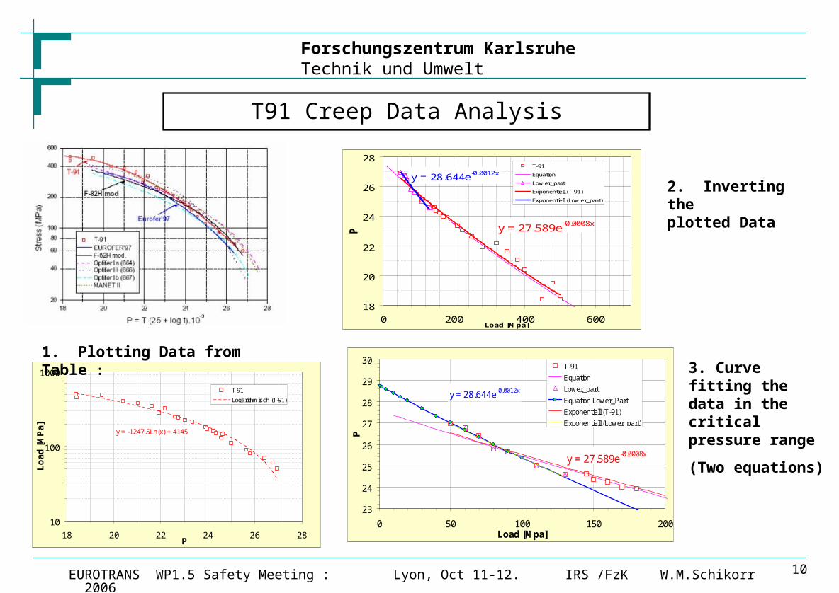
T91 Creep Data Analysis
y = -1247.5Ln(x) + 4145
10
100
1000
18 20 22 24 26 28P
Lo
ad
[M
Pa
]
T-91
Logarithmisch (T-91)
y = 27.589e-0.0008x
y = 28.644e-0.0012x
18
20
22
24
26
28
0 200 400 600Load [Mpa]
P
T-91
Equation
Low er_part
Exponentiell (T-91)
Exponentiell (Low er_part)
y = 27.589e-0.0008x
y = 28.644e-0.0012x
23
24
25
26
27
28
29
30
0 50 100 150 200Load [Mpa]
PT-91
Equation
Lower_part
Equation Lower_Part
Exponentiell (T-91)
Exponentiell (Lower_part)
1. Plotting Data from Table :
2. Inverting the plotted Data
3. Curve fitting the data in the critical pressure range
(Two equations)
Forschungszentrum KarlsruheTechnik und Umwelt
IRS /FzK W.M.SchikorrEUROTRANS WP1.5 Safety Meeting : Lyon, Oct 11-12. 2006 11
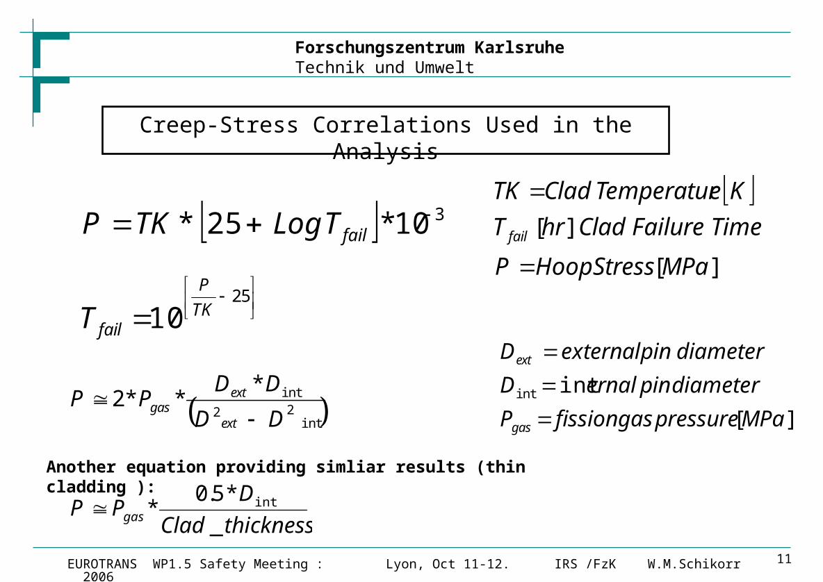
Creep-Stress Correlations Used in the Analysis
310*25* failTLogTKP
25
10 TK
P
failT
int22
int***2
DD
DDPP
ext
extgas
][
intint
MPapressuregasfissionP
diameterpinernalD
diameterpinexternalD
gas
ext
thicknessClad
DPP gas _
*5.0* int
Another equation providing simliar results (thin cladding ):
][
][
MPaStressHoopP
TimeFailureCladhrT
KeTemperaturCladTK
fail
Forschungszentrum KarlsruheTechnik und Umwelt
IRS /FzK W.M.SchikorrEUROTRANS WP1.5 Safety Meeting : Lyon, Oct 11-12. 2006 12
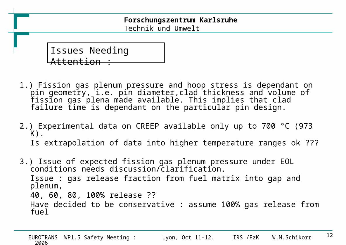
Issues Needing Attention :
1.) Fission gas plenum pressure and hoop stress is dependant on pin geometry, i.e. pin diameter,clad thickness and volume of fission gas plena made available. This implies that clad failure time is dependant on the particular pin design.
2.) Experimental data on CREEP available only up to 700 °C (973 K). Is extrapolation of data into higher temperature ranges ok ???
3.) Issue of expected fission gas plenum pressure under EOL conditions needs discussion/clarification. Issue : gas release fraction from fuel matrix into gap and plenum,
40, 60, 80, 100% release ??Have decided to be conservative : assume 100% gas release from fuel

Forschungszentrum KarlsruheTechnik und Umwelt
IRS /FzK W.M.SchikorrEUROTRANS WP1.5 Safety Meeting : Lyon, Oct 11-12. 2006 13
T91 Clad Failure Time as Function of Clad Temperature and Fission Gas Pressure for XT-ADS Design : Pin = 6.55mm OD, clad thickness = 0.475mm, 580mm Lower Gas Plenum
1. Design Criteria:
Clad Failure ≥30 min under ULOFss conditions at EOL
2. Adopted :
50 bar (5 Mpa) as design fission gas plenum pressure for peak pin at EOL
3. This implies :
for peak pin :
Tclad_max < 847 °C under ULOFss conditions at EOL
Plenum Gas Pressure [ Mpa] 3 Mpa 4 Mpa 5 Mpa 7 Mpa 10 Mpa
Clad failure time <
10 000 hr 696 688 681 666 643
1 000 hr 731 723 715 699 676
100 hr 768 760 751 735 711
10 hr 808 799 791 774 749
1 hr 851 842 833 816 790
30 min 865 856 847 829 803
2 min 921 912 902 884 856
Expected T-91 Clad Failure Times
(best estimate reference values)
Clad temperature [°C] : mid wall
Forschungszentrum KarlsruheTechnik und Umwelt
IRS /FzK W.M.SchikorrEUROTRANS WP1.5 Safety Meeting : Lyon, Oct 11-12. 2006 14
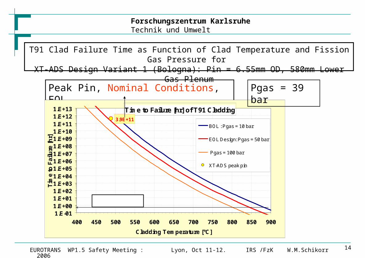
T91 Clad Failure Time as Function of Clad Temperature and Fission Gas Pressure for XT-ADS Design Variant 1 (Bologna): Pin = 6.55mm OD, 580mm Lower Gas Plenum
Peak Pin, Nominal Conditions, EOL
Time to Failure [hr] of T91 Cladding3.9E+11
1.E-011.E+001.E+011.E+021.E+031.E+041.E+051.E+061.E+071.E+081.E+091.E+101.E+111.E+121.E+13
400 450 500 550 600 650 700 750 800 850 900
Cladding Temperature [°C]
Tim
e t
o F
ailu
re [
hr]
BOL : Pgas = 10 bar
EOL Design: Pgas = 50 bar
Pgas = 100 bar
XT-ADS peak pin
30 min Failure Limit
Pgas = 39 bar
Forschungszentrum KarlsruheTechnik und Umwelt
IRS /FzK W.M.SchikorrEUROTRANS WP1.5 Safety Meeting : Lyon, Oct 11-12. 2006 15
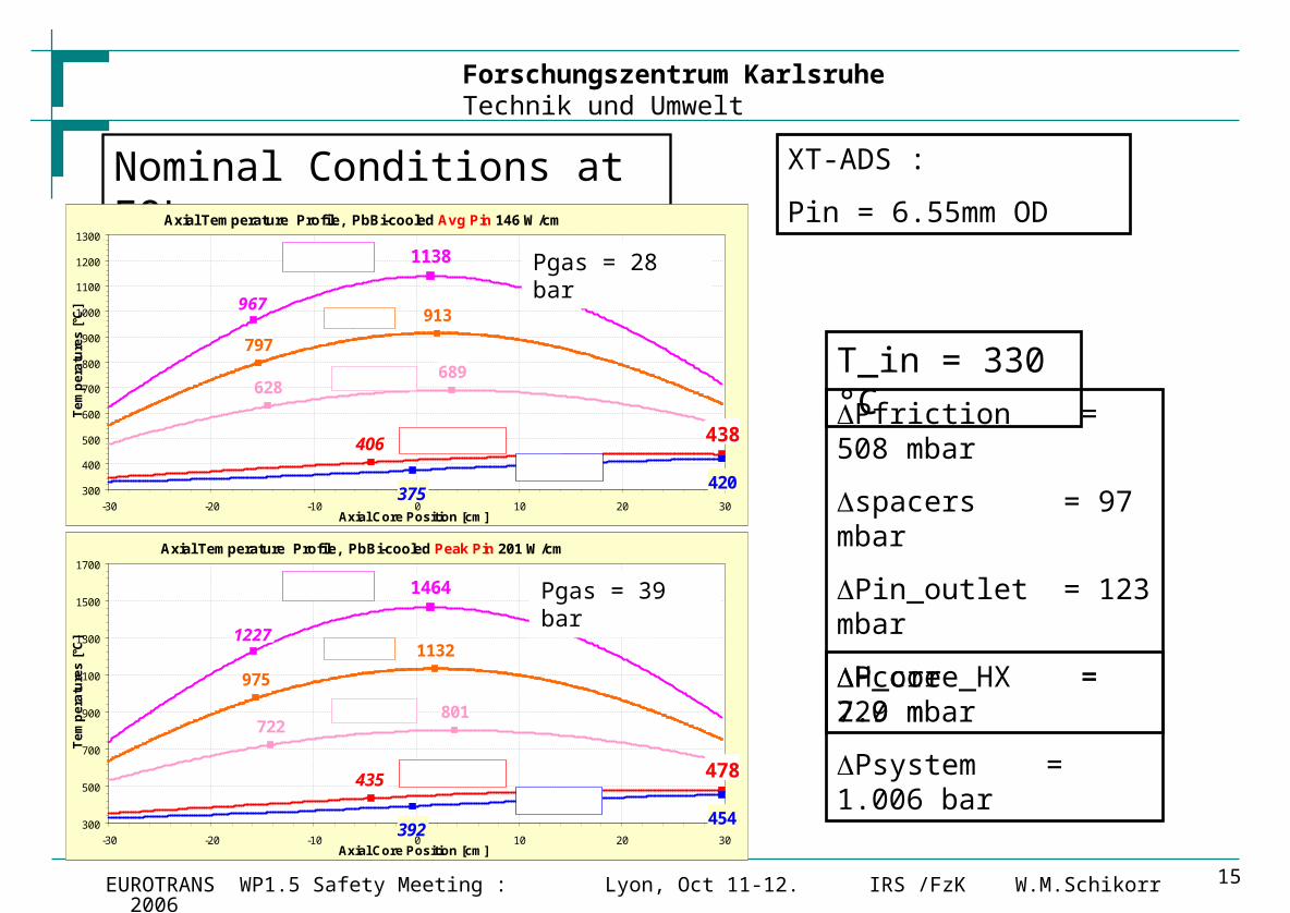
XT-ADS :
Pin = 6.55mm OD
T_in = 330 °C
Nominal Conditions at EOL :
Pfriction = 508 mbar
spacers = 97 mbar
Pin_outlet = 123 mbar
Pcore = 729 mbar
Psystem = 1.006 bar
Axial Temperature Profile, PbBi-cooled Avg Pin 146 W/cm
406
375420
438
967
797
913
628689
1138
300
400
500
600
700
800
900
1000
1100
1200
1300
-30 -20 -10 0 10 20 30Axial Core Position [cm]
Te
mp
era
ture
s [
°C]
Cladding surf
Coolant
Center Fuel
Surf Fuel
Avg Fuel
Axial Temperature Profile, PbBi-cooled Peak Pin 201 W/cm
435
392454
478
1227
975
1132
722801
1464
300
500
700
900
1100
1300
1500
1700
-30 -20 -10 0 10 20 30Axial Core Position [cm]
Te
mp
era
ture
s [
°C]
Cladding surf
Coolant
Center Fuel
Surf Fuel
Avg Fuel
H_core_HX = 2.0 m
Pgas = 28 bar
Pgas = 39 bar
Forschungszentrum KarlsruheTechnik und Umwelt
IRS /FzK W.M.SchikorrEUROTRANS WP1.5 Safety Meeting : Lyon, Oct 11-12. 2006 16
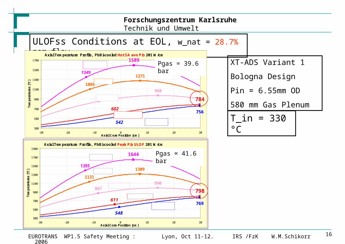
XT-ADS Variant 1
Bologna Design
Pin = 6.55mm OD
580 mm Gas Plenum
T_in = 330 °C
ULOFss Conditions at EOL, w_nat = 28.7% nom flow
Axial Temperature Profile, PbBi-cooled Peak Pin ULOF 201 W/cm
611
548
769
798
1395
1131
1309
867990
1644
300
500
700
900
1100
1300
1500
1700
1900
-30 -20 -10 0 10 20 30Axial Core Position [cm]
Tem
per
atu
res
[°C
]
Cladding surf
Coolant
Center Fuel
Surf Fuel
Avg Fuel
Axial Temperature Profile, PbBi-cooled Hot SA avg Pin 201 W/cm
602
542
756
784
1349
1099
1271
849968
1589
300
500
700
900
1100
1300
1500
1700
-30 -20 -10 0 10 20 30Axial Core Position [cm]
Te
mp
era
ture
s [
°C]
Cladding surf
Coolant
Center Fuel
Surf Fuel
Avg Fuel
Pgas = 41.6 bar
Pgas = 39.6 bar
Forschungszentrum KarlsruheTechnik und Umwelt
IRS /FzK W.M.SchikorrEUROTRANS WP1.5 Safety Meeting : Lyon, Oct 11-12. 2006 17
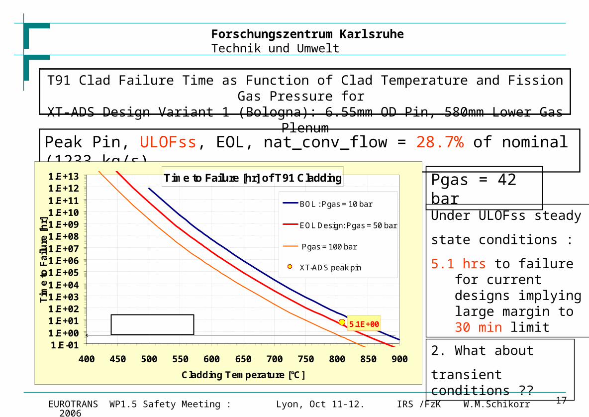
T91 Clad Failure Time as Function of Clad Temperature and Fission Gas Pressure for XT-ADS Design Variant 1 (Bologna): 6.55mm OD Pin, 580mm Lower Gas Plenum
Peak Pin, ULOFss, EOL, nat_conv_flow = 28.7% of nominal (1233 kg/s)
Time to Failure [hr] of T91 Cladding
5.1E+00
1.E-011.E+001.E+011.E+021.E+031.E+041.E+051.E+061.E+071.E+081.E+091.E+101.E+111.E+121.E+13
400 450 500 550 600 650 700 750 800 850 900
Cladding Temperature [°C]
Tim
e t
o F
ailu
re [
hr]
BOL : Pgas = 10 bar
EOL Design: Pgas = 50 bar
Pgas = 100 bar
XT-ADS peak pin
30 min Failure Limit
2. What about
transient conditions ??
Pgas = 42 bar
Under ULOFss steady
state conditions :
5.1 hrs to failure for current designs implying large margin to 30 min limit
Forschungszentrum KarlsruheTechnik und Umwelt
IRS /FzK W.M.SchikorrEUROTRANS WP1.5 Safety Meeting : Lyon, Oct 11-12. 2006 18
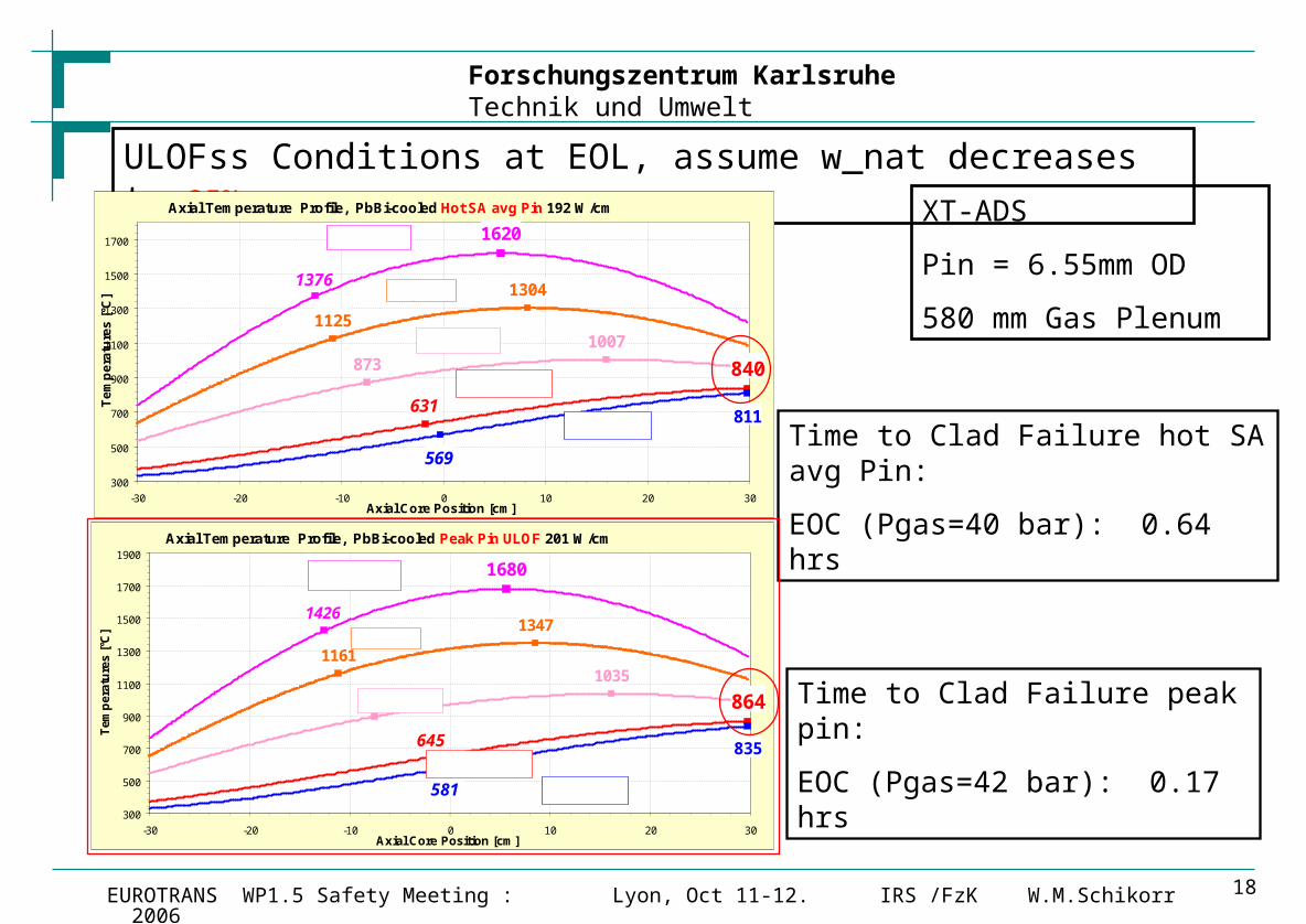
XT-ADS
Pin = 6.55mm OD
580 mm Gas Plenum
Time to Clad Failure hot SA avg Pin:
EOC (Pgas=40 bar): 0.64 hrs
ULOFss Conditions at EOL, assume w_nat decreases to 25% nom
Axial Temperature Profile, PbBi-cooled Peak Pin ULOF 201 W/cm
645
581
835
864
1426
1161
1347
896
1035
1680
300
500
700
900
1100
1300
1500
1700
1900
-30 -20 -10 0 10 20 30Axial Core Position [cm]
Tem
per
atu
res
[°C
]
Cladding surf
Coolant
Center Fuel
Surf Fuel
Avg Fuel
Axial Temperature Profile, PbBi-cooled Hot SA avg Pin 192 W/cm
631
569
811
840
1376
1125
1304
8731007
1620
300
500
700
900
1100
1300
1500
1700
-30 -20 -10 0 10 20 30Axial Core Position [cm]
Te
mp
era
ture
s [
°C]
Cladding surf
Coolant
Center Fuel
Surf Fuel
Avg Fuel
Time to Clad Failure peak pin:
EOC (Pgas=42 bar): 0.17 hrs
Forschungszentrum KarlsruheTechnik und Umwelt
IRS /FzK W.M.SchikorrEUROTRANS WP1.5 Safety Meeting : Lyon, Oct 11-12. 2006 19
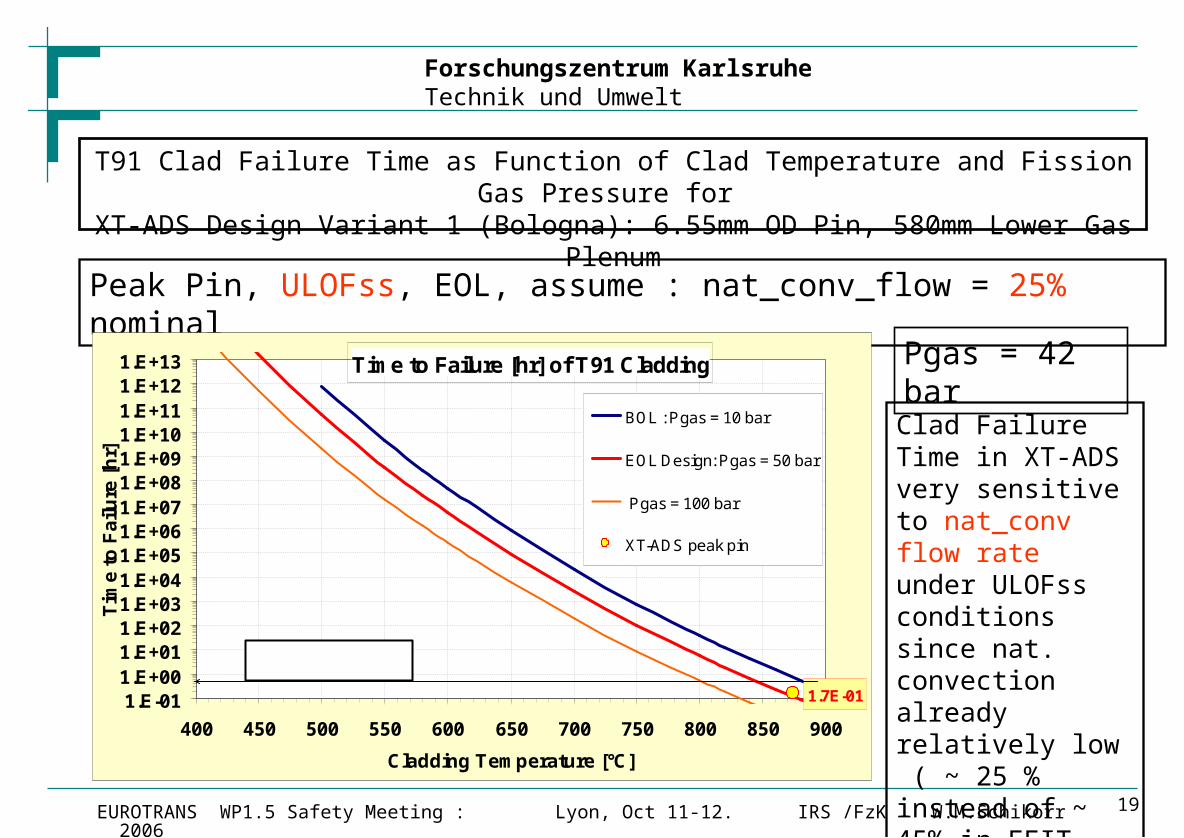
T91 Clad Failure Time as Function of Clad Temperature and Fission Gas Pressure for XT-ADS Design Variant 1 (Bologna): 6.55mm OD Pin, 580mm Lower Gas Plenum
Peak Pin, ULOFss, EOL, assume : nat_conv_flow = 25% nominal
Time to Failure [hr] of T91 Cladding
1.7E-011.E-011.E+001.E+011.E+021.E+031.E+041.E+051.E+061.E+071.E+081.E+091.E+101.E+111.E+121.E+13
400 450 500 550 600 650 700 750 800 850 900
Cladding Temperature [°C]
Tim
e t
o F
ailu
re [
hr]
BOL : Pgas = 10 bar
EOL Design: Pgas = 50 bar
Pgas = 100 bar
XT-ADS peak pin
30 min Failure Limit
Clad Failure Time in XT-ADS very sensitive to nat_conv flow rate under ULOFss conditions since nat. convection already relatively low ( ~ 25 % instead of ~ 45% in EFIT and XADS)
Pgas = 42 bar
Forschungszentrum KarlsruheTechnik und Umwelt
IRS /FzK W.M.SchikorrEUROTRANS WP1.5 Safety Meeting : Lyon, Oct 11-12. 2006 20
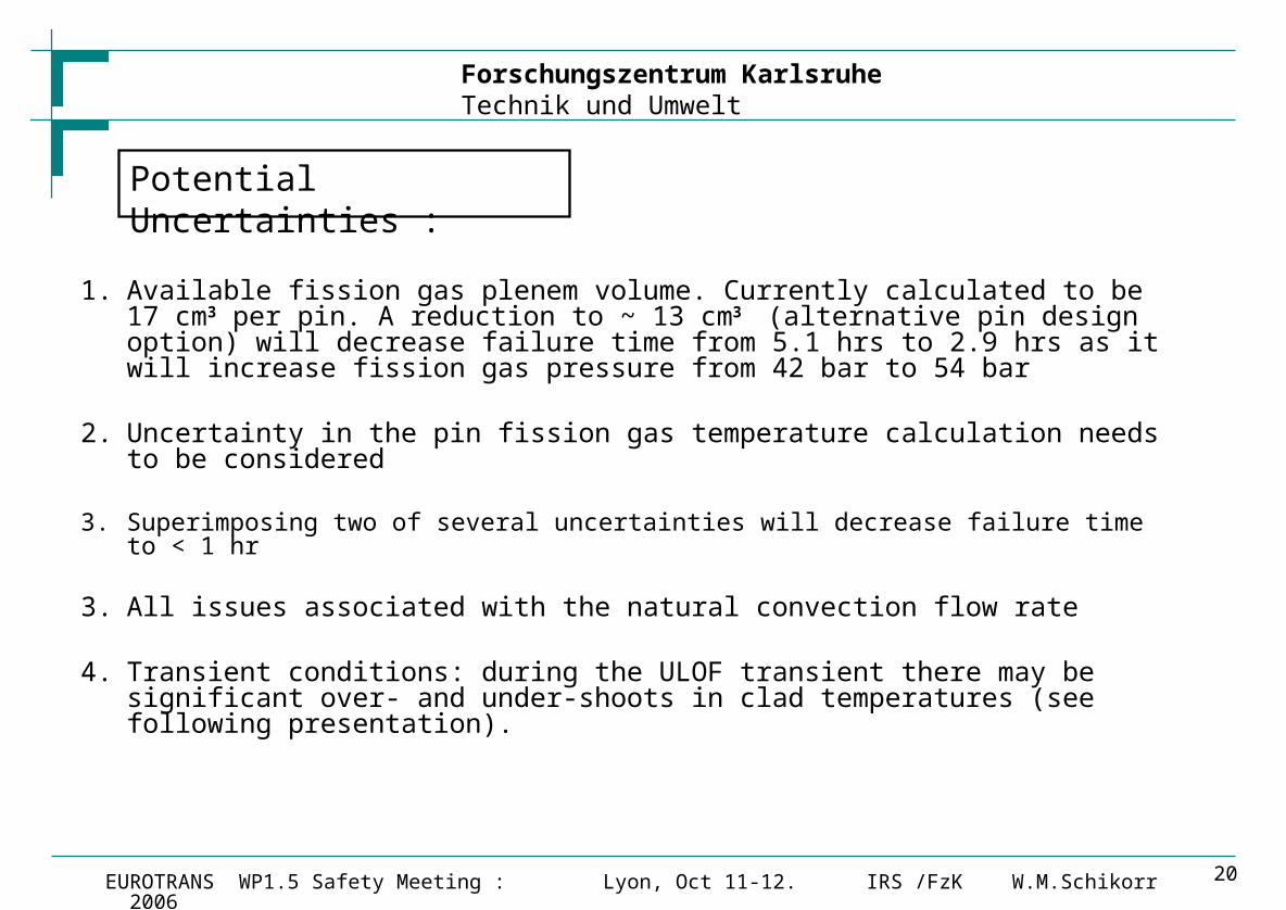
Potential Uncertainties :
1. Available fission gas plenem volume. Currently calculated to be 17 cm3 per pin. A reduction to ~ 13 cm3 (alternative pin design option) will decrease failure time from 5.1 hrs to 2.9 hrs as it will increase fission gas pressure from 42 bar to 54 bar
2. Uncertainty in the pin fission gas temperature calculation needs to be considered
3. Superimposing two of several uncertainties will decrease failure time to < 1 hr
3. All issues associated with the natural convection flow rate
4. Transient conditions: during the ULOF transient there may be significant over- and under-shoots in clad temperatures (see following presentation).
Forschungszentrum KarlsruheTechnik und Umwelt
IRS /FzK W.M.SchikorrEUROTRANS WP1.5 Safety Meeting : Lyon, Oct 11-12. 2006 21
Conclusions on T-91 Material Property Limits (1/2 ) :
1.) EMBRITTLEMENT makes it advisable to select T_in ~ 330 °C following SPIRE and DEMETRA recommendations.
2.) CORROSION issues require that the maximum clad temperatures of the peak pin are below 500 °C under nominal conditions (unless the clad material is coated thereby increasing the temperature limit to ~ 550 °C) limiting core heat up to 90 °C.
3.) New T91 CREEP Data from CIEMAT should be taken into consideration during all transients especially those leading to clad temperatures > 850 °C.
Forschungszentrum KarlsruheTechnik und Umwelt
IRS /FzK W.M.SchikorrEUROTRANS WP1.5 Safety Meeting : Lyon, Oct 11-12. 2006 22
Conclusions on T-91 Material Property Limits (2/2) :
4.) Under ULOF steady state conditions max. cladding temperatures between
800 °C – 900 °C should be expected.
For T_in = 330 °C, T_clad_max (ULOF) : 800 °C – 865 °C
corresponding clad failure time due to creep ranging from 5 hrs to 0.17 hrs
For the 30 min limit, the maximum temperature of the clad should not exceed 847 °C
6) The issue of high temperature corrosion still needs to be assessed / evaluated in view of experimental data currently assembled (DEMETRA)
5.) The current design (580mm lower gas plenum) is comfortably achieving the 30 min design goal as clad failure time limit under ULOFss and EOL conditions.