für Märklin H0-Lokomotiven mit Trommelkollektor … › damcontent › 02 › fa ›...
24
60760 H0 Nachrüst-Decoder Set für Märklin H0-Lokomotiven mit Trommelkollektor-Motor
Transcript of für Märklin H0-Lokomotiven mit Trommelkollektor … › damcontent › 02 › fa ›...
60760
H0 Nachrüst-Decoder Set für Märklin H0-Lokomotiven mit Trommelkollektor-Motor
2
Hinweis: Der Umbau darf nur durch autorisiertes Fachperso-nal durchgeführt werden (z.B. Märklin Digital-Fachhändler). Anderenfalls entfallen die Garantieansprüche.
Vorbereitung• Prüfen, ob die Lok mechanisch in Ordnung ist.• Prüfen, ob das Set zur Lok und zum Motor-Typ passt.• Die elektrische Belastung des Decoders prüfen.
Zuordnen der Zusatzfunktionen des Decoders Max. Belastbarkeit am Motorausgang 800 mA Max. Belastbarkeit am Funktionsausgang 150 mA Max. Gesamt-Belastbarkeit, kurzzeitig 1100 mA => Maximal 2 Glühlampen 610 080 oder 1 Glühlampe 610 040 pro Funktionsausgang.
Motor einbauen 1. Schritt: Motorschild, Anker, Feldspule und Elektronik
oder Fahrtrichtungsumschalter entfernen. 2. Schritt: Kondensatoren C2 und C3 ersatzlos vom Motor-
schild entfernen.3. Schritt: Getriebe prüfen und gegebenenfalls aufbereiten.4. Schritt: Neuen Feldmagnet, Anker und Motorschild
montieren.
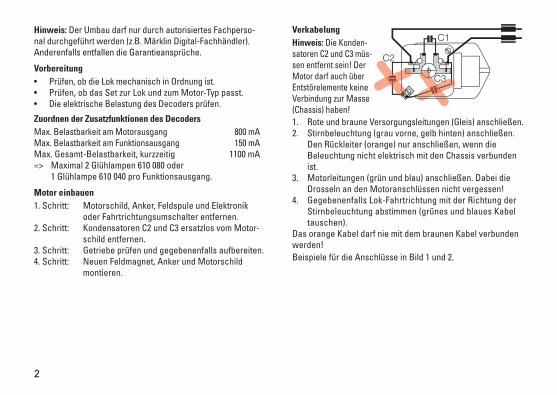
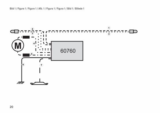
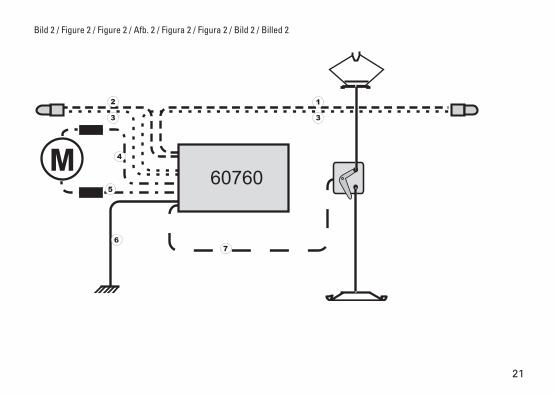
Verkabelung Hinweis: Die Konden-satoren C2 und C3 müs-sen entfernt sein! Der Motor darf auch über Entstörelemente keine Verbindung zur Masse (Chassis) haben! 1. Rote und braune Versorgungsleitungen (Gleis) anschließen. 2. Stirnbeleuchtung (grau vorne, gelb hinten) anschließen.
Den Rückleiter (orange) nur anschließen, wenn die Beleuchtung nicht elektrisch mit den Chassis verbunden ist.
3. Motorleitungen (grün und blau) anschließen. Dabei die Drosseln an den Motoranschlüssen nicht vergessen!
4. Gegebenenfalls Lok-Fahrtrichtung mit der Richtung der Stirnbeleuchtung abstimmen (grünes und blaues Kabel tauschen).
Das orange Kabel darf nie mit dem braunen Kabel verbunden werden! Beispiele für die Anschlüsse in Bild 1 und 2.
3
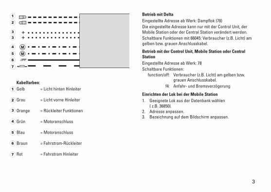
Kabelfarben:Gelb = Licht hinten Hinleiter
Grau = Licht vorne Hinleiter
Orange = Rückleiter Funktionen
Grün = Motoranschluss
Blau = Motoranschluss
Braun = Fahrstrom-Rückleiter
Rot = Fahrstrom Hinleiter
Betrieb mit DeltaEingestellte Adresse ab Werk: Dampflok (78)Die eingestellte Adresse kann nur mit der Control Unit, der Mobile Station oder der Central Station verändert werden. Schaltbare Funktionen mit 66045: Verbraucher (z.B. Licht) am gelben bzw. grauen Anschlusskabel.
Betrieb mit der Control Unit, Mobile Station oder Central StationEingestellte Adresse ab Werk: 78Schaltbare Funktionen: function/off: Verbraucher (z.B. Licht) am gelben bzw.
grauen Anschlusskabel. f4: Anfahr- und Bremsverzögerung
Einrichten der Lok bei der Mobile Station1. Geeignete Lok aus der Datenbank wählen
( z.B. 36850).2. Adresse anpassen.3. Bezeichnung auf dem Bildschirm anpassen.
1
2
3
4
5
6
7
1
2
3
4
5
6
7
3
4
Note: The conversion must be done by an authorized techni-cian (example: Märklin digital dealer). Conversion work done by anyone else will void the manufacturer‘s warranty.
Preparation • Check to make sure that the locomotive is in proper
mechanical condition. • Check to make sure that this conversion set is the right
one for the locomotive and the type of motor.• Check electrical load on the decoder.
Assigning Auxiliary Functions to the Decoder Maximum load at the motor output 800 milliampsMaximum load at the function output 150 milliampsMaximum total, short term load 1100 milliampsA maximum of 2 no. 610 080 light bulbs or 1 no. 610 040 light bulb per function output.
Installing the Motor 1. Step: Remove the brush plate, armature, field, and
electronic circuit or reverse unit. 2. Step: Remove the condensers C2 and C3 from the
brush plate.3. Step: Check the gear drive and renew if necessary.4. Step: Install the new field, armature, and brush plate.
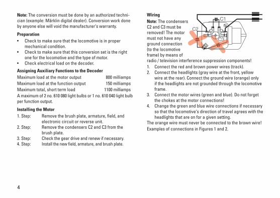
Wiring Note: The condensers C2 and C3 must be removed! The motor must not have any ground connection (to the locomotive frame) by means of radio / television interference suppression components! 1. Connect the red and brown power wires (track). 2. Connect the headlights (gray wire at the front, yellow
wire at the rear). Connect the ground wire (orange) only if the headlights are not grounded through the locomotive frame.
3. Connect the motor wires (green and blue). Do not forget the chokes at the motor connections!
4. Change the green and blue wire connections if necessary so that the locomotive‘s direction of travel agrees with the headlights that are on for a given setting.
The orange wire must never be connected to the brown wire! Examples of connections in Figures 1 and 2.
5
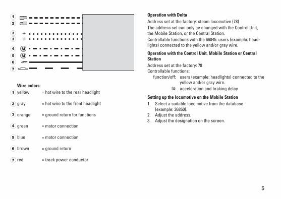
Wire colors:yellow = hot wire to the rear headlight
gray = hot wire to the front headlight
orange = ground return for functions
green = motor connection
blue = motor connection
brown = ground return
red = track power conductor
Operation with DeltaAddress set at the factory: steam locomotive (78) The address set can only be changed with the Control Unit, the Mobile Station, or the Central Station. Controllable functions with the 66045: users (example: head-lights) connected to the yellow and/or gray wire.
Operation with the Control Unit, Mobile Station or Central StationAddress set at the factory: 78 Controllable functions: function/off: users (example: headlights) connected to the
yellow and/or gray wire. f4: acceleration and braking delay
Setting up the locomotive on the Mobile Station1. Select a suitable locomotive from the database
(example: 36850).2. Adjust the address.3. Adjust the designation on the screen.
1
2
3
4
5
6
7
1
2
3
4
5
6
7
3
6
Remarque : La transformation peut être exécutée uniquement par du personnel compétent autorisé (tels que des détaillants spécialisés en Märklin-Digital). Toute prétention à garantie est sinon exclue.
Préparation• Vérifier si la locomotive est mécaniquement fonctionnelle.• Vérifier si le set convient pour cette locomotive et pour le
type de moteur.• Vérifier la charge électrique du décodeur.
Affectation des fonctions supplémentaires du décodeurCapacité de charge maximale à la sortie moteur 800 mACapacité de charge maximale à la sortie fonction 150 mACapacité de charge maximale globale momentané 1100 mAAu maximum 2 lampes à incandescence réf. 610 080 ou 1 lampe à incandescence réf. 610 040 par sortie fonction.
Monter le moteur1re étape : Retirer la plaque du moteur, l’induit, la bobine in-
ductrice et le module électronique ou l’inverseur du sens de marche.
2e étape : Retirer les condensateurs C2 et C3 de la plaque du moteur sans les remplacer.
3e étape : Vérifier la transmission et l’adapter le cas échéant.
4e étape : Monter les nouveaux électro-aimants in-ducteurs, induit et plaque de moteur.
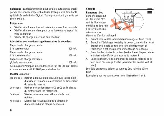
CâblageRemarque : Les condensateurs C2 et C3 doivent être retirés ! Le moteur ne doit pas être relié à la terre (châssis), même via des éléments d’antiparasitage ! 1. Brancher les câbles d’alimentation rouge et brun (voie). 2. Brancher l’éclairage frontal (gris devant, jaune à l’arrière).
Brancher le câble de retour (orange) uniquement si l’éclairage n’est pas électriquement relié au châssis.
3. Brancher les câbles du moteur (vert et bleu). Ne pas oublier le ballast inductif aux connexions du moteur !
4. Le cas échéant, faire concorder le sens de marche de la loco avec l’éclairage frontal (permuter les câbles vert et bleu).
Le câble orange ne doit en aucun cas être relié au câble brun ! Exemples pour les connexions : voir illustrations 1 et 2.
7
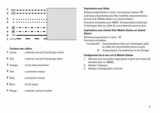
Couleurs des câbles:Jaune = amenée courant d’éclairage arrière
Gris = amenée courant d’éclairage avant
Orange = fil de retour fonctions
Vert = connexion moteur
Bleu = connexion moteur
Brun = fil de retour
Rouge = amenée courant traction
Exploitation avec Delta Adresse programmée à l‘usine : Locomotive à vapeur (78)L’adresse programmée peut être modifiée uniquement avec Control Unit, Mobile Station ou Central Station. Fonctions activables avec 66045 : Consommateurs (tels que l’éclairage) reliés au câble de raccordement jaune ou gris.
Exploitation avec Control Unit, Mobile Station ou Central StationAdresse programmée à l‘usine : 78 Fonctions activables : function/off : Consommateurs (tels que l’éclairage) reliés
au câble de raccordement jaune ou gris. f4 : Temporisation d‘accélération et de freinage
Configuration de la loco sur la Mobile Station1. Sélectio nner locomotive appropriée à partir de la base de
données (par ex. 36850).2. Adapter l’adresse.3. Adapter la désignation à l’écran.
1
2
3
4
5
6
7
1
2
3
4
5
6
7
3
8
Opmerking: de ombouw mag alleen door de geautoriseerde vakmensen uitgevoerd worden (bijv. Märklin digitaal-winke-lier), anders vervalt de aanspraak op garantie.
Voorbereiding• controleer of de loc mechanisch in goede staat is.• controleer of de set bij de loc en het motortype past.• controleer de elektrische belasting van de decoder.
Toewijzen van de functie-uitgangen van de decoderMax. belasting motoruitgang 800 mAMax. belasting aan de functie-uitgang 150 mAMax. totale decoder belasting kortstondig 1100 mAMaximaal twee gloeilampen 610 080 of één gloeilamp 610 040 per functie-uitgang.
Motor inbouwenStap 1: motorschild, anker, veldspoel en elektronica of
rijrichtingrelais verwijderen.Stap 2: condensatoren c2 en c3 zonder deze te vervan-
gen van het motorschild verwijderen.Stap 3: aandrijving controleren en indien nodig herstel-
len of onderhoud uitvoeren.Stap 4: nieuwe veldmagneet, anker en motorschild
monteren.
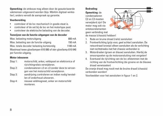
Bedrading:Opmerking: de condensatoren C2 en C3 moeten verwijderd zijn! De motor mag ook via ontstoorelementen geen verbinding met de massa (chassis) hebben!1. Rode en bruine draad (rails) aansluiten2. Frontverlichting (grijs voor, geel achter) aansluiten. De
retourdraad (oranje) alleen aansluiten als de verlichting niet rechtstreeks met het chassis verbonden is
3. Motordraden (groen en blauw) aansluiten. Hierbij de smoorspoelen op de motoraansluiting niet vergeten!
4. Eventueel de rijrichting van de loc afstemmen met de richting van de frontverlichting (de groene en de blauwe draad verwisselen)
De oranje draad mag nooit met de bruine draad (chassis) verbonden worden!Voorbeelden voor het aansluiten in figuur 1 en 2.
9
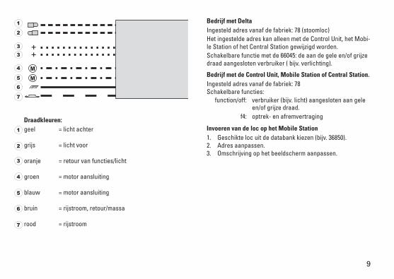
Draadkleuren:geel = licht achter
grijs = licht voor
oranje = retour van functies/licht
groen = motor aansluiting
blauw = motor aansluiting
bruin = rijstroom, retour/massa
rood = rijstroom
Bedrijf met Delta Ingesteld adres vanaf de fabriek: 78 (stoomloc)Het ingestelde adres kan alleen met de Control Unit, het Mobi-le Station of het Central Station gewijzigd worden.Schakelbare functie met de 66045: de aan de gele en/of grijze draad aangesloten verbruiker ( bijv. verlichting).
Bedrijf met de Control Unit, Mobile Station of Central Station.Ingesteld adres vanaf de fabriek: 78 Schakelbare functies: function/off: verbruiker (bijv. licht) aangesloten aan gele
en/of grijze draad. f4: optrek- en afremvertraging
Invoeren van de loc op het Mobile Station1. Geschikte loc uit de databank kiezen (bijv. 36850).2. Adres aanpassen.3. Omschrijving op het beeldscherm aanpassen.
1
2
3
4
5
6
7
1
2
3
4
5
6
7
3
10
Nota: La modificación debe ser ejecutada exclusivamente por personal competente autorizado (p. ej., distribuidores profe-sionales de Märklin Digital). En caso contrario se pierden los derechos de garantía.
Preparativos• Comprobar si la locomotora está mecánicamente en orden.• Comprobar si el set cuadra con la loco y el modelo de
motor.• Comprobar la casga eléctrica que soporta el decoder.
Asignar las funciones auxiliares del decoderCarga máx. admisible en la salida del motor 800 mACarga máx. admisible en la salida de función 150 mACarga máx. admisible total, breve duración 1100 mAMáx. 2 lámparas de incandescencia 610 080 o 1 lámpara de incandescencia 610 040 por cada salida de función
Montaje del motor1er paso: Desmontar la tapa del motor, el inducido, la bobina de excitación y la electrónica o el conmutador del sentido de marcha.2º paso: Desmontar los condensadores C2 y C3, sin sustituirlos, de la tapa del motor.3er paso: Inspeccionar el reductor y, en su caso, acondicionar.4º paso: Montar un imán de excitación, un inducido y una tapa de motor nuevos.
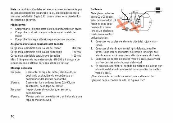
CableadoNota: ¡Los condensa-dores C2 y C3 deben estar desnomtados! ¡El motor no debe estar conectado a masa (chasis), ni siquiera a través de elementos antiparasitarios! 1. Conectar los cables de alimentación (vía) rojos y mar-
rones.2. Conectar el alumbrado frontal (gris delante, amarillo
atrás). Conectar el conductor de retorno (naranja) si el alumbrado no está conectado eléctricamente al chasis.
3. Conectar los cables del motor (verde y azul). ¡No olvidar las reactancias en los bornes del motor!
4. En su caso, coordinar el sentido de marcha de la loco con el sentido del alumbrado frontal (intercambiar los cables verde y azul).
¡Nunca conectar el cable naranja con el cable marrón!Ejemplos de las conexiones de las figuras 1 y 2.

11
Colores de los cables:Amarillo =Luces cola, conductor ida
Gris = Luces cabeza, conductor ida
Naranja = Conductor retorno Funciones
Verde = Conexión del motor
Azul = Conexión del motor
Marrón = Conductor retorno corriente tracción
Rojo = Conductor ida corriente tracción
Funcionamiento con DeltaDirección configurada de fábrica: locomotora de vapor (78)La dirección configurada se puede modificar únicamente con la Control Unit, la Mobile Station o la Central Station. Funciones gobernables con el 66045: aparatos receptores (p. ej., luces) conectados al cable de conexión amarillo o gris.
Funcionamiento con la Control Unit, la Mobile Station o la Central StationDirección configurada de fábrica: 78Funciones gobernables: function/off: aparatos receptores (p. ej. luces) conecta-
dos al cable de conexión amarillo o gris. f4: retardo de arranque y frenado
Configuración de la loco con la Mobile Station1. Seleccionar una locomotora adecuada de la base de
datos (p. ej., 36850).2. Configurar la dirección.3. Editar la designación en la pantalla.
1
2
3
4
5
6
7
1
2
3
4
5
6
7
3
12
Avvertenza: Tale trasformazione deve venire eseguita soltanto da parte di personale specializzato autorizzato (ad es. un riven-ditore specialista Märklin Digital). In caso differente decadono le richieste di garanzia.
Preparativi• Verificate se la locomotiva è meccanicamente in ordine.• Controllate se tale corredo è adatto alla locomotiva ed al
tipo di motore.• Verificate il carico elettrico del Decoder.
Assegnazione delle funzioni ausiliarie del DecoderMax. capacità di carico all’uscita per il motore 800 mAMax. capacità di carico all’uscita per le funzioni 150 mAMax. capacità di carico complessiva,per un tempo breve 1100 mAAl massimo 2 lampadine 610 080 oppure1 lampadina 610 040 per ogni uscita di funzione
Montaggio del motore1. passo: rimuovere piastra di chiusura del motore, indotto,
bobina di campo e circuito elettronico oppure commutatore della direzione di marcia.
2. passo: rimuovere dalla piastra di chiusura del motore i condensatori C2 e C3 che non vanno sostituiti.
3. passo: verificare la trasmissione e se necessario metterla a punto.
4. passo: montare il nuovo magnete di campo, indotto e piastra di chiusura del motore.
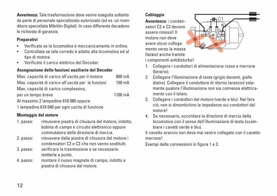
CablaggioAvvertenza: i conden-satori C2 e C3 devono essere rimossi! Il motore non deve avere alcun collega-mento verso la massa (telaio) anche tramite i componenti antidisturbo!1. Collegare i conduttori di alimentazione rosso e marrone
(binario).2. Collegare l’illuminazione di testa (grigio davanti, giallo
dietro). Collegare il conduttore di ritorno (arancio) sola-mente qualora l’illuminazione non sia connessa elettrica-mente con il telaio.
3. Collegare i conduttori del motore (verde e blu). Nel fare ciò, non si dimentichino le impedenze sui conduttori del motore!
4. Se necessario, accordare la direzione di marcia della locomotiva con il senso dell’illuminazione di testa (scam-biare i cavetti verde e blu).
Il cavetto arancio non deve mai venire collegato con il cavetto marrone!Esempi delle connessioni in figura 1 e 2.
13
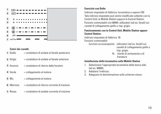
Colori dei cavetti:Giallo = conduttore di andata al fanale posteriore
Grigio = conduttore di andata al fanale anteriore
Arancio = conduttore di ritorno delle funzioni
Verde = collegamento al motore
Blu = collegamento al motore
Marrone = conduttore di ritorno corrente di trazione
Rosso = conduttore di andata corrente di trazione
Esercizio con DeltaIndirizzo impostato di fabbrica: locomotiva a vapore (78)Tale indirizzo impostato può venire modificato soltanto con la Control Unit, la Mobile Station oppure la Central Station.Funzioni commutabili con 66045: utilizzatori (ad es. fanali) sui cavetti di collegamento giallo o risp. grigio.
Funzionamento con la Control Unit, Mobile Station oppure Central Station.Indirizzo impostato di fabbrica: 78Funzioni commutabili: function accesa/spenta: utilizzatori (ad es. fanali) sui
cavetti di collegamento giallo o risp. grigio.
f4: ritardo di avviamento e di frenatura
Installazione della locomotiva sulla Mobile Station1. Selezionare l’appropriata locomotiva dalla banca dati (ad es. 36850).2. Adattare l’indirizzo.3. Adeguare la denominazione sullo schermo visore.
1
2
3
4
5
6
7
1
2
3
4
5
6
7
3
14
Observera: Montage och ombyggnad får endast göras av fackkunnig personal (t.ex. av Märklin auktoriserade digital-fackhandlare). Annars gäller inte några garantier.
Förberedelser• Kontrollera att loket fungerar mekaniskt.• Kontrollera att satsen passar till loket och denna motor-
typ.• Kontollera att dekodern klarar el-belastningarna.
Fördelning av dekoderns tilläggsfunktionerMax. belastning av motor-utgången 800 mAMax. belastning av vardera funktionsutgången 150 mAMax. total belastning, endast tillfälligt 1.100 mAMax. totalt 2 glödlampor 610 080 eller 1 glödlampa 610 040 per funktionsutgång.
Inbyggnad/montage av motorSteg 1: Avlägsna motorsköld, ankare, fältspole samt
elektronik och eventuellt körriktnings-relä.Steg 2: Avlägsna kondensatorerna C2 och C3 helt från
motorskölden. De skall tas bort helt och ej ersättas.Steg 3: Kontrollera växellåda/drivenhet och gör i ordning
den för montage.Steg 4: Montera den nya fältmagneten, ankaret och
motorskölden.
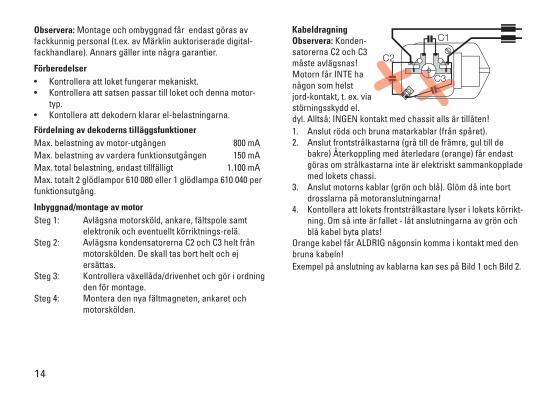
KabeldragningObservera: Konden-satorerna C2 och C3 måste avlägsnas! Motorn får INTE ha någon som helst jord-kontakt, t. ex. via störningsskydd el. dyl. Alltså: INGEN kontakt med chassit alls är tillåten!1. Anslut röda och bruna matarkablar (från spåret).2. Anslut frontstrålkastarna (grå till de främre, gul till de
bakre) Återkoppling med återledare (orange) får endast göras om strålkastarna inte är elektriskt sammankopplade med lokets chassi.
3. Anslut motorns kablar (grön och blå). Glöm då inte bort drosslarna på motoranslutningarna!
4. Kontollera att lokets frontstrålkastare lyser i lokets körrikt-ning. Om så inte är fallet - låt anslutningarna av grön och blå kabel byta plats!
Orange kabel får ALDRIG någonsin komma i kontakt med den bruna kabeln!Exempel på anslutning av kablarna kan ses på Bild 1 och Bild 2.
15
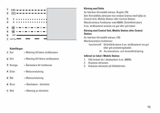
Kabelfärger:Gul = Matning till bakre strålkastare
Grå = Matning till främre strålkastare
Orange = Återledare för funktioner
Grön = Motoranslutning
Blå = Motoranslutning
Brun = Återledare - körström
Röd = Matning av körström
Körning med DeltaAv fabriken förinställd adress: Ånglok (78)Den förinställda adressen kan endast ändras med hjälp av Control Unit, Mobile Station eller Central Station.Manövrerbara Funktioner med 66045: Strömförbrukare(t.ex. strålkastare) ansluts via gul eller grå kabel.
Körning med Control Unit, Mobile Station eller Central StationAv fabriken förinställd adress: (78)Manövererbara funktioner: function/off: Strömförbrukare (t.ex. strålkastare) via gul
eller grå anslutningskabel. f4: Accelerations- och bromsfördröjning
Införsel av loket i Mobile Station1. Välj önskat lok i databanken (t.ex. 36850).2. Anpassa adressen.3. Anpassa adressen på bildskärmen.
1
2
3
4
5
6
7
1
2
3
4
5
6
7
3
16
Bemærk: Ombygningen må kun foretages af autoriseret fag-personale (f. eks. Märklin Digital-forhandler). Ellers bortfalder alle garantikrav.
Forberedelse• Kontrollér, at lokomotivet er mekanisk i orden.• Kontrollér, at sættet passer til lokomotivet og motortypen.• Kontrollér dekoderens elektriske belastning.
Placering af dekoderens tillægsfunktionerMaks. belastning ved motorudgang 800 mAMaks. belastning ved funktionsudgang 150 mA.Maks. samlet belastning, kortvarig 1100 mA.Maks. 2 pærer 610 080 eller 1 pære 610 040 pr. funktionsud-gang.
Indbygning af motorTrin 1: Fjern motorskilt, anker, feltspole og elektronik
eller fartretningsomkobler.Trin 2: Fjern kondensatorer C2 og C3 fra motorskiltet.Trin 3: Kontrollér drev og foretag arbejder efter behov. Trin 4: Montér ny feltmagnet, anker og motorskilt.
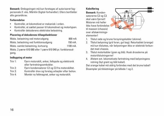
KabelføringBemærk: Konden-satorerne C2 og C3 skal være fjernet! Motoren må heller ikke have forbindelse til massen (chassis) over afskærmnings-elementer!1. Tilslut røde og brune forsyningskabler (skinne).2. Tilslut belysning (grå foran, gul bag). Returkablet (orange)
må kun tilsluttes, når belysningen ikke er elektrisk forbun-det med chassis.
3. Tilslut motorkabler (grøn og blå). Husk drosslerne på motortilslutningerne!
4. Afstem evt. lokomotivets fartretning med belysningens retning (byt grønt og blåt kabel).
Det orange kabel må aldrig forbindes med det brune kabel!Eksempler på tilslutninger på billede 1 og 2.
17
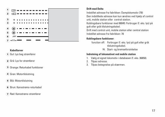
KabelfarverGul: Lys bag strømfører
Grå: Lys for strømfører
Orange: Returkabel funktioner
Grøn: Motortilslutning
Blå: Motortilslutning
Brun: Kørestrøms-returkabel
Rød: Kørestrøms-strømfører
Drift med DeltaIndstillet adresse fra fabrikken: Damplokomotiv (78)Den indstillede adresse kan kun ændres ved hjælp af control unit, mobile station eller central station. Koblingsbare funktioner med 66045: Forbruger (f. eks. lys) på gult eller gråt tilslutningskabel. Drift med control unit, mobile station eller central stationIndstillet adresse fra fabrikken: 78
Koblingsbare funktioner: function off: Forbruger (f. eks. lys) på gult eller gråt
tilslutningskabel. f4: Start- og bremseforsinkelse
Indretning af lokomotivet ved mobile station1. Vælg et egnet lokomotiv i databasen (f. eks. 36850).2. Tilpas adresse.3. Tilpas betegnelse på skærmen.
1
2
3
4
5
6
7
1
2
3
4
5
6
7
3
18
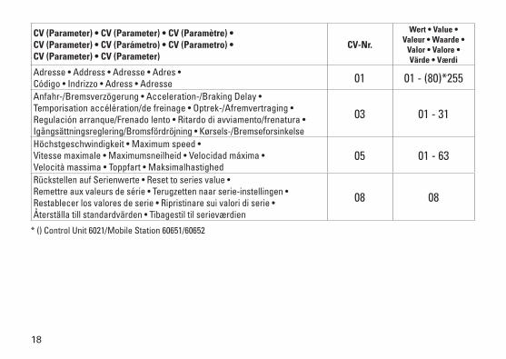
CV (Parameter) • CV (Parameter) • CV (Paramètre) • CV (Parameter) • CV (Parámetro) • CV (Parametro) • CV (Parameter) • CV (Parameter)
CV-Nr.
Wert • Value • Valeur • Waarde •
Valor • Valore • Värde • Værdi
Adresse • Address • Adresse • Adres • Código • Indrizzo • Adress • Adresse 01 01 - (80)*255Anfahr-/Bremsverzögerung • Acceleration-/Braking Delay • Temporisation accélération/de freinage • Optrek-/Afremvertraging • Regulación arranque/Frenado lento • Ritardo di avviamento/frenatura • Igångsättningsreglering/Bromsfördröjning • Kørsels-/Bremseforsinkelse
03 01 - 31
Höchstgeschwindigkeit • Maximum speed • Vitesse maximale • Maximumsneilheid • Velocidad máxima • Velocità massima • Toppfart • Maksimalhastighed
05 01 - 63
Rückstellen auf Serienwerte • Reset to series value • Remettre aux valeurs de série • Terugzetten naar serie-instellingen • Restablecer los valores de serie • Ripristinare sui valori di serie • Återställa till standardvärden • Tibagestil til serieværdien
08 08
* () Control Unit 6021/Mobile Station 60651/60652
19
20
60760
Bild 1 / Figure 1 / Figure 1 / Afb. 1 / Figura 1 / Figura 1 / Bild 1 / Billede 1
12
3
4
5
6 7
3
21
60760
Bild 2 / Figure 2 / Figure 2 / Afb. 2 / Figura 2 / Figura 2 / Bild 2 / Billed 2
12
3
4
5
67
3
22
23
101677/1019/Sc10EfÄnderungen vorbehalten
© Gebr. Märklin & Cie. GmbHwww.maerklin.com/en/imprint.html
Gebr. Märklin & Cie. GmbH Stuttgarter Str. 55 - 57 73033 Göppingen Germanywww.maerklin.com