Gebrauchsanleitung - Download...
20
Gebrauchsanleitung Manual 52292 Doppel-Multiplexer für 2 Lichtsignale mit Multiplex-Technologie Double multiplexer for 2 daylight signals with multiplex technology 1. Wichtige Hinweise ...................................... 2 2. Einführung / Eigenschaften ........................ 2 3. Anschluss ................................................... 3 4. Konfiguration .............................................. 6 5. Digital Ansteuerung ....................................... 10 6. Signal-Logik ............................................... 11 7. Technische Daten ...................................... 16 1. Important Information ................................. 2 2. Introduction / Properties ............................. 2 3. Wiring........................................................... 3 4. Configuration .............................................. 7 5. Digital Control................................................. 10 6. Signal Logic ............................................... 11 7. Technical Data ........................................... 16
Transcript of Gebrauchsanleitung - Download...

GebrauchsanleitungManual
52292
Doppel-Multiplexerfür 2 Lichtsignale mit Multiplex-Technologie
Double multiplexerfor 2 daylight signals with multiplex technology
1. Wichtige Hinweise ...................................... 22. Einführung / Eigenschaften ........................ 23. Anschluss ................................................... 34. Konfiguration.............................................. 65. Digital Ansteuerung ....................................... 106. Signal-Logik ............................................... 117. Technische Daten ...................................... 16
1. Important Information ................................. 22. Introduction / Properties ............................. 23. Wiring........................................................... 34. Configuration .............................................. 75. Digital Control................................................. 106. Signal Logic ............................................... 117. Technical Data ........................................... 16

2
DE EN1. Wichtige HinweiseLesen Sie vor der ersten Benutzung des Pro-duktes bzw. dessen Einbau diese Anleitung voll-ständig und aufmerksam durch. Bewahren Sie diese Anleitung auf. Sie ist Teil des Produktes.
Das Produkt richtig verwendenDas Produkt darf ausschließlich dieser Anleitung gemäß verwendet werden. Dieses Steuermodul ist bestimmt – zum Einbau in Modelleisenbahnanlagen, – zum Anschluss an einen zugelassenen Mo-
dellbahntransformator mit einer Ausgangs-spannung von max. 16 V~ bzw. an einer damit versorgten Steuerung (z. B. Viess-mann Commander 5300),
– zum Betrieb in trockenen Räumen. – zur Ansteuerung von Signalen
mit Multiplex-TechnologieJeder darüber hinausgehende Gebrauch gilt als nicht bestimmungsgemäß. Für daraus resultie-rende Schäden haftet der Hersteller nicht.
2. Einführung / EigenschaftenBeim Doppel-Multiplexer 52292 handelt es sich um ein Steuermodul mit integriertem Digitaldeco-der (MM, DCC) für zwei Viessmann Hauptsignale mit Multiplex-Technologie z.B. Ks-Signale (Art.-Nr. 4040 - 4046) und Standard-Lichtsignale (Art.-Nr. 4720 - 4730). Das Modul steuert zwei unabhäng-gige Hauptsignale und erkennt die angeschlos-senen Signale automatisch. Bilden Haupt- und Vorsignal eine Einheit (Hp/Vr-Kombinationen), können diese auch mit eigenen Adressen unab-hängig voneinander gesteuert werden. Dieses Modul ist die ideale Steuerung für die Viessmann Signalbrücke 4750 - das Modul steu-ert alle montierten Signale (Art.-Nr. 4750 - 4753) zuverlässig. Das Modul verfügt über analoge Ein-gänge für das Tastenstellpult 5547. Die Signale können auch über Gleiskontakte und durch digi-tale Schaltbefehle geschaltet werden. Der Viess-mann SpeedBus (LSB) ermöglicht den komfor-tablen Anschluss an den Viessmann Commander mit automatischer Anmeldung.Das Modul hat keinen Signalbus.Der Signalanschluss erfolgt über eine einzige Steckverbindung. Weicher Lichtwechsel zwischen den Signalbildern sowie weitere Eigenschaften sind einstellbar.
1. Important hints Please read this manual carefully and take note of the comments regarding safety PRIOR to us-ing this product! Please keep this manual and the packaging for possible later use. They are part of this product.
Using the product in the right manner
This product may only be used according to the instructions stated in this manual. This control module is intended for use as follows:
– Installation on model train layouts – For connection to an approved model train
transformer with an output voltage of max. 16 V~ or a digital command station (e.g.: Viessmann Commander 5300)
– For operation in dry rooms – For connection to daylight signals suitable
for multiplex technologyAny other use is not considered to be in accord-ance with regulations. The manufacturer is not liable for any damage that may be caused by in-appropriate use.
2. Introduction / properties The double multiplexer 52292 is a control module with integral digital decoder (MM, DCC) for two Viessmann main signals suitable for multiplex technology e.g.: Ks signals (part numbers 4040 - 4046) and standard daylight signals (part numbers 4720 - 4730). The module controls up to two in-dependent main signals and detects the connect-ed signals automatically. If a main signal and a distant signal are combined on one mast they can still be controlled separately by assigning different addresses to them. This module is the ideal option for controlling the Viessmann signal gantry 4750. The module relia-bly controls all signal types installed on the gantry (part numbers 4750 - 4753). The module also has analogue inputs for a push button control panel such as the Viessmann 5547. The signal can also be controlled via track contacts. The SpeedBus (LSB) facilitates the comfortable electrical connec-tion with automatic detection and recognition of the signal by the Viessmann Commander.This module cannot be wired to the signal bus.The signals are wired by simply inserting the plug into the appropriate socket of the module. Soft change between signal aspects (fading) as well as

3
SignalbilderundAdressenfindenSieaufdenSei-ten 19 und 20. Der Doppel-Multiplexer erkennt automatisch den angeschlossenenSignaltypundkonfiguriertsichentsprechend.In Verbindung mit dem Viessmann Commander (Anschluss am LSB) kann sich das Modul auto-matischdigitalkonfigurieren.Bei Verwendung anderer Digitalzentralen bzw. im analogen Betrieb werden Optionen über DIP-Schalter (siehe Abb. 5 auf Seite 8) und gegebe-nenfalls auch Digitaladressen manuell eingerich-tet. Bei diesem Vorgang werden gleichzeitig die EigenschaftendeszusteuerndenSignalskonfi-guriert:• sofortiges oder weiches Überblenden
der Signalbilder• gekoppeltes Signal (nur Hp0 und Hp2)• Bahnhofs- oder Blocksignal-Logik• Bremsmodul ja / neinDieeinmaleingestellteKonfigurationunddasak-tuelle Signalbild werden intern gespeichert und bei jedem Spielbeginn wieder zurückgeholt.
Vorsignal Verfügen die am Doppel-Multiplexer angeschlos-senen Hauptsignale über ein Vorsignal am glei-chen Mast, dann gehört dieses Vorsignal „am Mast“ funktional zum folgenden Hauptsignal und kann auch so angesteuert werden.Es erhält somit die erforderlichen Informationen über die Digitaladresse des zugehörigen Hauptsignals und zeigt das entsprechende Signalbild an. Der Vorsignalbegriff wird über die jeweilige Digital-adresse des zugehörigen Hauptsignals übertra-gen.In den Stellungen „Halt“ oder „Rangierverbot auf-gehoben“ wird das Vorsignal am eigenen Mast automatisch dunkel geschaltet. Diese „Dunkel-tastung“ entspricht dem Vorbild, denn wer nicht weiterfahren darf, braucht die Stellung des näch-sten Hauptsignals nicht zu kennen.Einzeln stehende separate Vorsignale können am Doppel-Multiplexer nicht angeschlossen werden.
Update Der Doppel-Multiplexer ist aktualisierbar. Mit dem Viessmann Commander und einem Windows PC können Sie jederzeit selbst eine neue Software-Version über den LSB auf den Multiplexer auf-spielen.DieBeschreibungfindenSieimjewei-ligen Update-Paket und die einzelnen Schritte im
other parameters can be adjusted.You will find possible signal aspects and address-es on pages 19 and 20.The double multiplexer auto-detects the type of signal connected and configures itself accordingly. When wired to the Viessmann Commander via the LSB the double multiplexer will configure itself au-tomatically (programming the digital address). When using other makes of digital command sta-tions or when operating in analogue mode various options can be switched on or off by setting DIP switches as shown in Fig. 5 on page 8. If applica-ble digital addresses may also be assigned manu-ally. During this process the parameters of the signal to be controlled will be configured simulta-neously:• Immediate or soft change of signal aspects
(fading)• Locked signal with two aspects only (“Stop”
or “Proceed at limited speed”)• Yard or block interlocking logic• Brake module: yes / no
The set configuration and the signal aspects will be saved in the module and will be restored when-ever the control system is switched on again.
Distant signal
If the signals connected to the double multiplexer consist of a main signal as well as a distant signal mounted to the same mast then the latter is logi-cally linked to the following main signal. Therefore it must be controlled like its correspond-ing main signal by assigning the same address to both signals. Thus the distant signal will always display the as-pect of its corresponding main signal. If the main signal on the same mast displays “Stop” or “Shunting permitted” then the distant signal on that mast will automatically be switched off (dark aspect).This is quite prototypical since the engineer must not know the aspect of the fol-lowing main signal if he is not allowed to proceed that far. Individually installed distant signals cannot be wired to the double multiplexer.
Update
The double multiplexer can be updated. With the aid of the Viessmann Commander and a Windows PC you can install the latest software version onto the double multiplexer via the LSB. You will find the description in the relevant update pack-

4
Fig. 1Abb. 1
1. 2.
3. 4. 5.
Kabel in Schraubklemme befestigen
Draht einschiebenDraht umbiegen
Litzen verdrillenKabel abisolieren
Schraube festziehenInsert wire Bend wire
Twist wiresStrip insulation
Fixing wires to terminals
Tighten screw
5 mm
Wiring for conventional (analogue) operation
In analogue mode the double multiplexer only offers limited functionality. Both signals only have two aspects that can be controlled via the analogue inputs, namely “Hp0” (red) and “Hp1” (green). Multi-aspect signals configured as locked signals (DIP switches 2 & 3 on) can switch be-tween “Stop” or “Proceed at limited speed”. You can activate the first and second signal as-pect in analogue mode for instance with the aid of
entsprechenden Menü auf dem Viessmann Com-mander.
3. AnschlussStecken Sie den Signalstecker in die entspre-chende Buchse des Doppel-Multiplexers. Achten Sie auf die korrekte Polarität. Die Markierung am Stecker muss mit der Markierung am Multiplexer übereinstimmen. Sollte der Stecker umgedreht eingesteckt werden (vertauschte Polung) entste-hen keine Schäden. Allerdings wird das Signal dann nicht richtig erkannt und deshalb inkorrekt angesteuert.Zum Anschluss des Doppel-Multiplexers an die Steuerung Ihrer Modellbahn (Stellpulte, Digital-zentrale) beachten Sie bitte die unten stehenden Hinweise sowie die Abbildungen 1 bis 4.
Alle Anschluss- und Montagearbeiten dür-fen nur bei abgeschalteter Betriebsspan-nung durchgeführt werden(Ausnahme: LSB Anschluss und Signalan-schluss)Verwenden Sie nur nach VDE / EN gefer-tigte Modellbahntransformatoren!Sichern Sie die Stromquellen unbedingt so ab, dass es bei einem Kurzschluss nicht zum Kabelbrand kommen kann!
Konventioneller (analoger) AnschlussIm Analogbetrieb bietet der Doppel-Multiplexer eine eingeschränkte Funktionalität. Beide Signale haben je zwei Stellungen, die über die analo-gen Eingänge steuerbar sind: Hp0 (rot) und Hp1 (grün).MehrbegriffigeSignale,dieaufgekoppeltkonfiguriertsind(DIP-Schalter2und3on) schal-ten zwischen Hp0 (rot) und Hp2 (grün & gelb). Den ersten und zweiten Begriff schalten Sie im Analogbetrieb z.B. mit Hilfe des Viessmann Tastenstellpults5547(fürvierzweibegriffigeSignale). So entsprechen Farbe und Anordnung der Tasten dem jeweiligen Signalbild und dessen Stellmöglichkeiten (rot & grün). Analog lassen sich über ein Stellpult am 52292 maximal zwei Begriffe schalten.Eine Steuerung der weiteren Begriffe (dritter und vierter Begriff) ist im analogen Betrieb mit dem 52292 nicht möglich (Ausnahme DIP-Schalter 2 und 3 sind on, d.h.: das Signal ist auf gekoppelt konfiguriert).Moderne Ks-Signale haben teilweise vier oder mehr Signalbegriffe und sollten sinnvollerweise di-gital angesteuert werden.
age and the individual steps in the menue on the Viessmann Commander.
3. WiringInsert the plug of the signal into the appropriate socket of the double multiplexer. Please observe the correct polarity. The mark on the plug must be aligned with the mark on the double multiplexer. Inserting the plug the wrong way around (wrong polarity) will not result in any damage. However, the signal cannot be detected correctly and con-trol of the signal will be unpredictable.Please observe the hints below and figures 1 to 4 regarding the wiring of the double multiplexer to your control system (push button panels, digital command station).
Make sure that the power supply is switched off during installation and electri-cal connection of the device!The only exceptions are connecting the LSB cables and the signal plugs. They can be plugged in even when the power is turned on.Only use model train transformers bearing the VDE / EN mark for your power supply!Protect the power supply units in order to prevent the risk of short circuits or the wir-ing catching fire!

5
the push button panel 5547 (for four two-aspect signals). Thus colour and arrangement of the push buttons correspond with the signal aspects (red or green). In analogue mode one can only switch two signal aspects with the 52292. Activat-ing the third and fourth signal aspect cannot be accomplished with the 52292 with one exception: If the DIP switches 2 & 3 are switched on and therefore the signal is configured for a locked type two-aspect signal. Some modern Ks signals may have four or more signal aspects and should therefore be controlled in digital mode.
Hint for DC operation: Please observe the correct polarity in DC mode: Red = plus, brown = minus
Diorama mode
In order to enliven dioramas or exhibits it may be desirable to change the signal aspects in an auto-mated but arbitrary sequence. In order to activate this mode simply connect all four analogue inputs (Hp0 and Hp1) with each other and with the brown wire from the transformer and then turn on the power.This mode remains active until the power is turned off again.
Analoger AnschlussWiring for analogue operation
Die beiden COM Anschlüsse des Doppel-Multiple-xers sind intern miteinander verbunden. Sie müs-sen mit dem Anschluss „rt“ verbunden werden.
Hinweis Gleichstrombetrieb:Beachten Sie beim Betrieb mit Gleichstrom unbedingt die Polarität: rot = plus, braun = minus
Diorama-ModusZur Belebung von Dioramen oder Schaustücken kann es gewünscht sein, die Signalstellung in einer willkürlich ablaufenden Sequenz zu verändern. Um diesen Modus zu aktivieren, verbinden Sie einfach die vier Analoganschlüsse Hp0 und Hp1 miteinander und mit dem braunen Kabel vom Trafo und schalten anschließend die Stromversorgung ein. Dieser Modus bleibt solange aktiv bis die Stromversorgung wieder ausgeschaltet wird.
Abb. 2 Fig. 2

6
Digitaler Anschluss (am Gleis) Beim Digitalbetrieb verbinden Sie die Klemmen „rt“ und „bn“ mit dem Gleisausgang einer Digital-zentrale oder eines Boosters (Abb. 3 auf Seite 6). Parallel zu einer Digitalzentrale können Sie ein externes Tastenstellpult an den Doppel-Multiplexer anschließen und so auch von Hand zwei Signalbegriffe steuern. Allerdings wird in diesem Fall die Stellinformation nicht an die Digitalzentrale gemeldet.
Wiring for digital operation (directly to the tracks)
For digital operation please connect the terminals “rt” and “bn” with the track outputs of your com-mand station or a booster (see Fig. 3 on page 6). In addition you may also connect a push but-ton panel to your double multiplexer for manual control of the signals. However, the manually activated signal aspect will not be reported to the command station.
Digitaler Anschluss am LSB Sofern Sie den Viessmann Commander als Digi-talzentrale verwenden, sollten Sie den Doppel-Multiplexer über den leistungsfähigen SpeedBus LSB anschließen (Abb. 4 auf Seite 7). Nutzen Sie zur Verbindung von LSB-Geräten bitte unse-re speziellen LSB-Kabel (Artikel-Nr. 5390 - 5393). Diese sind mit Steckern konfektioniert und sofort einsetzbar. Die beiden LSB-Buchsen des Dop-pel-Multiplexers sind parallel geschaltet. Verbin-den Sie eine der beiden Buchsen per LSB-Kabel mit dem Viessmann Commander. An die andere Buchse können Sie weitere LSB-Geräte anschlie-ßen. Die Verbindung zum Viessmann Comman-der kann auch indirekt über weitere LSB-Geräte erfolgen.
Wiring for digital operation via LSB
If you are the proud owner of a Viessmann Com-mander we recommend connecting the double multiplexer via the powerful SpeedBus LSB as per Fig. 4 on page 7. For easy installation we rec-ommend our special LSB cables (part numbers 5390 – 5393). They are ready-made complete with plugs. The LSB sockets of the double mul-tiplexer are internally connected. Therefore you can plug in the LSB cable into either LSB socket. Use the other one for extending the wiring to other LSB devices. It is immaterial if you connect the double multiplexer directly to the LSB socket of the Viessmann Commander or to any other LSB device that is already connected to the Viessmann Commander.
Digitaler Anschluss am GleisWiring for digital operation (directly to the tracks)
Fig. 3Abb. 3
Config
Adresse
Signal 2
(Signal 2)
Signal 1
Viessmann
Mu
ltip
le
xe
r 5
22
92
fr L
ich
tsig
na
le
ü
rt bn Hp1Hp0COM
rt bn
BremsenBremsen Hp0 Hp1Hp0 Hp1
16 V ~/ Dig.
16 V ~/ Dig.
LS
B
COM Bremsen
Signal 1
Spannung / Voltagemind. 15 V bei Verwendung von 5227min. 15 V when using 5227
Mot. / DCC
Digitalzentrale / Booster
rot / red braun / brown
rot / red

7
Der Doppel-Multiplexer meldet sich dann automa-tisch am Viessmann Commanderanundkonfigu-riertsichselbst(Autokonfiguration).Die zwei Stelleingänge des Multiplexers Hp0 und Hp1 lassen sich optional auch als Rückmeldekon-takte für den Betrieb einer Blockstrecke verwen-den (siehe Abb. 6).Die Eingänge „Bremsen“ können für das ziel-genaue Schalten eines Bremsmoduls (Märklin-Motorola) oder eines Bremsgenerators (DCC) für das jeweilige Hauptsignal verwendet werden. Be-achten Sie bitte die Hinweise im Abschnitt „Ver-wendung eines Bremsmoduls / Bremsgenerators“.Die Bremsmodule bzw. die Bremsgeneratoren werden jeweils über ein monostabiles Relais am jeweiligen Schaltausgang des 52292 angeschlos-sen.
As mentioned before the double multiplexer will be automatically detected by the Viessmann Com-mander and auto-configure itself. The two inputs “Hp0” and “Hp1” of the double multiplexer may also be used as feedback inputs for operating automated block sectors as shown in Fig. 6. The inputs “Bremsen” (“Braking”) may be utilised for precise switching of a brake module (Maerklin Motorola) or a brake generator (DCC) for the re-spective main signal. Please observe the remarks in the chapter “Using a brake module / brake gen-erator”. The brake modules resp. the brake generators will be wired via a monostable relay to the corre-sponding output of the 52292.
Abb. 4 Digitaler Anschluss am LSBWiring for digital operation via LSB
Co
nfig
Adresse
Signal 2
(Signal 2)
Signal 1
Viessmann
Multiplexer 52292
fr Lichtsignale
ü
rt bn Hp1Hp0COM
rt bn
BremsenBremsen Hp0 Hp1Hp0 Hp1
16 V ~/ Dig.
16 V ~/ Dig.
LS
B
COM Bremsen
Signal 1
rot / red
braun / brown
LSB5390 – 5391 –5392 – 5393 –
16 V ~ / =LSB
28 cm60 cm
215 cm600 cm z.B. / e.g. 5200
rot / red
Fig. 4

8
ON
1 2 3 4 5 6 7 8
WnP
DIP-Schalter
Ein
Aus
DIP-Switch
/ On
/ Off
Fig.5Abb. 5 DIP switchesDIP-Schalter
4. KonfigurationNach Anschluss des Doppel-Multiplexers muss dieserkonfiguriertwerden.NurbeiAnschlussüberden LSB an den Viessmann Commander kann dieKonfigurationautomatischerfolgen.Informationen zum Anschluss des Multiplexers an den Viessmann CommanderfindenSieimRefe-renzhandbuch für den Viessmann Commander.
Optionen Die möglichen Signaloptionen werden über die DIP-Schalter („Mäuseklavier“) des Doppel-Multi-plexers eingestellt (siehe Tabelle auf Seite 9). Die Stellung des DIP-Schalters wird beim Einschalten des Moduls oder nach einem kurzen Druck auf die Taste „Adresse“ eingelesen. Der Doppel-Multiplexer übernimmt die Einstel-lungen und liest das angeschlossene Signal neu ein. Dieses blinkt während des Erkennungsvor-ganges kurz auf.
4. ConfigurationThe double multiplexer must be configured after connecting it to a power source. An automatic configuration of the double multiplexer is execut-ed, when connected to the Viessmann Command-er by the LSB only. You will find information about the connection of the double multiplexer to the Viessmann Commander in the reference hand-book of the Viessmann Commander.
Options
All potential signal options are set with the DIP switches on the double multiplexer (refer to the table on page 9). The setting of the DIP switches is read out once power is applied or when the “Ad-dress” button has been pressed shortly. The dou-ble multiplexer stores the settings and reads out the signal once again. The latter blinks during this detection process momentarily.
Viessmann Signalbuch 5299Mehr Informationen zur Aufstellung von Signalen und zu den vielfältigen Anschluss- möglichkeiten von Viessmann Signalenfin-den Sie im Viessmann Signalbuch (Artikel-Nr. 5299).
Viessmann signal handbook 5299You will find more information about the po-sitioning of signals and how to control them in the Viessmann signal handbook (5299). Currently this is only available in German.

9
Nr.No.
BezeichnungDescription
Schalter ausDIP switch “On”
Schalter einDIP switch “Off”
1 Signalbild
Signal aspect
direktes Überblenden der Signalbilder
Rapid switching of signal aspects
weiches Überblenden der Signalbilder
Fading of signal aspects
2 Gekoppelt 1
Signal type (signal 1)
ungekoppeltes Signal 1
Multi-aspect signal 1
gekoppeltes Signal 1 (Anzeige nur Hp0 und Hp2)
Dual aspect - “Hp0” and “Hp2” only (signal 1)
3 Gekoppelt 2
Signal type (signal 2)
ungekoppeltes Signal 2
Multi-aspect signal 2
gekoppeltes Signal 2 (Anzeige nur Hp0 und Hp2)
Dual aspect - “Hp0” and “Hp2” only (signal 2)
4 Unabhängiges Vorsignal 1(nur manuell in Motorola / DCC adressierbar)
Independent Distant signal 1 (address can only be programmed in Motorola / DCC format)
Vorsignal 1 ist nicht unabhängig adressierbar
Distant signal 1 cannot be programmed independently
Vorsignal 1 (falls vorhanden) ist unabhängig adressierbar
Distant signal 1 can be programmed independently
5 Unabhängiges Vorsignal 2 (nur manuell in Motorola / DCC addressierbar)
Independent Distant signal 2 (address can only be programmed in Motorola / DCC format)
Vorsignal 2 ist nicht unabhängig adressierbar
Distant signal 2 cannot be programmed independently
Vorsignal 2 (falls vorhanden) ist unabhängig adressierbar
Distant signal 2 can be programmed independently
6 Automatische Adressierung (nur in Motorola / DCC)
Automatic addressing (only in Motorola / DCC)
Jedes Signal kann eine unabhängige Basisadresse haben, inklusive der Vorsignale, falls die DIP-Schalter 4 oder 5 aktiv sind. Signale werden einzeln programmiert. Im LSB-Modus hat diese Einstellung keine Wirkung.
If the DIP switches 4 & 5 are active then each signal may have its own independent base address. Signals will be addressed individually. This setting has no effect in the LSB mode.
Alle am Multiplexer angeschlossenen Signale werden mit einem Befehl programmiert. Die Adressen der Signale werden automatisch vergeben und sind aufeinander folgend. Im LSB-Modus hat diese Einstellung keine Wirkung.
All signals connected to the double multiplexer will be programmed with one command. The (consecutive) addresses will be assigned automatically. This setting has no effect in the LSB mode.
7 Bremsmodul
Brake module
Nein.Bei rot zeigendem Signal wird der entspre-chendeRelaisausgangdasZugbeeinflus-sungsrelais sofort umschalten.
No.If the signal shows “Stop” then the corresponding relay output of the train control relay will be activated immediately.
Ja.Bei rot zeigendem Signal wird der entsprechende RelaisausgangdasZugbeeinflussungsrelaisschalten, wenn der Eingang “Bremsen” ein Signal vom Rückmelder erhält.
Yes.If the signal shows “Stop” then the corresponding relay output of the train control relay will be activated once the input “Bremsen” (Braking) receives a signal from the occupancy detector.
8 Bahnhofslogik/ Blockstreckenlogik
Yard logic / block interlocking logic
Bahnhofslogik: Signal wird vom Anwender gestellt
Yard logic: Signal will be set by the dispatcher
Blocksignallogik: Signal wird automatisch auf rot gestellt, wenn sich im folgenden Block ein Zug befindet.SoferndieserSchalter“on” gesetzt ist, ist die Grundstellung des Signals “grün”. Lediglich die Belegtmeldung schaltet das Signal über die Eingänge Hp0 und Hp1 auf rot. Die Zentrale kann das Signal in diesem Modus nicht stellen!
Block interlocking logic: Signal will be automati-cally set to “red” if there is a train in the following block. If this switch is set to “on” then the normal aspect is “green”. The signal is only controlled by the occupancy detectors and cannot be controlled by the command station!

10
5. Digitale Ansteuerung
Allgemeines:Das Modul benötigt zur Ansteuerung im Märklin-Motorola- und im NMRA-DCC-Betrieb pro Signal bis zu vier direkt aufeinander folgende Digital-Adressen.BeieinemmehrbegriffigenSignal,das mehr als eine Adresse benötigt, ist die erste Adresse immer eine ungerade Zahl. Am 52292 können bis zu drei externe Kontakte oder Taster pro Signal angeschlossen werden, über die das Signalmodul vom Zug aus geschal-tet werden kann. Zwei für die Stellungen „rot“ und „grün“ und der dritte Anschluss („Bremsen“) ist für den Bremskontakt, der beim Anschluss eines Bremsmoduls bzw. Bremsgenerators die Umschaltung der Stromversorgung von „Fahren“ (Zentrale / Booster) auf „Bremsen“ (Bremsmodul / Bremsgenerator) auslöst. Ohne Bremsmodul / Bremsgenerator wird die Fahrstromunterbrechung sofort wirksam, wenn das Signal auf „Halt“ gestellt wird. Die Ein- / Ausschaltung bzw. die Umschal-tung des Fahrstroms übernimmt ein monosta-biles Relais, das direkt am seitlichen Ausgang des 52292 angesteckt wird (siehe Abbildung 7).Das elektronische Relais 5227 besitzt je zwei Umschaltkontakte für jedes der beiden separa-ten Relais dieser Einheit. Ein Relais wird für die signalabhängige Schaltung des Fahrstroms wie oben beschrieben verwendet, das zweite kann für das zweite Signal am Doppel-Multiplexer ein-gesetzt werden. Mit den Umschaltkontakten kann jede Stromform, d.h. Gleichstrom, Wechselstrom und auch Digitalstrom geschaltet werden. Die ma-ximale Strombelastbarkeit der Kontakte beträgt 2 A.
ProgrammierungDer Viessmann Doppel-Multiplexer muss am Gleisausgang einer Zentrale angeschlossen sein. Während der Programmierung darf kein LSB Kabel angeschlossen sein. Ein langes Drücken des roten Programmiertasters (ca. zwei Sekunden) stellt das Modul auf Empfang im Programmiermodus und scannt gleichzeitig die angeschlossenen Signale. Es ist zu beachten, dass je nach Signaltyp eine unterschiedliche Anzahl von Digitaladressen benötigt wird. Eine Faustregel besagt, dass jedes Signal halb so viele Adressen (aufgerundet)
5. Digital control
General information:
The module may require up to four consecutive digital addresses for each signal in either digital mode (Motorola / DCC). The first address of a multi-aspect signal requiring more than one ad-dress is always an uneven number.You may connect up to three external contacts or push buttons for each signal wired to the 52292. This allows manual switching or activation by the trains. There are two inputs for the “Stop” and “Proceed” aspects and a third one for “Braking”. The latter is used for triggering the change over from normal “Driving” (powered by the command station or the booster) to “Braking” (powered by the brake module / brake generator). Without a braking device the track power will be interrupted immediately once the signal is set to “Stop”. The track power is switched by a monostable re-lay to be plugged directly onto the side of the dou-ble multiplexer. As shown in Fig. 7 the monostable relay 5227 consists of two relays with two sets of change over contacts each. One relay is used for switch-ing the track power subject to the signal aspect. The second relay may be used in the same man-ner for the second signal connected to the double multiplexer.The relay contacts can handle any type of current, that is DC, AC or digital current. The maximum current is 2A.
Programming
The Viessmann double multiplexer must be con-nected to the track output of a digital command station. During programming the LSB must be disconnected! Pressing the red programming button for about two seconds sets the module into reception mode (programming) while it scans the connected signals.Please note that the number of addresses re-quired depends on the type of signals wired to the module. As a rule of thumb it can be said that each signal needs about half as many address-

11
benötigt, wie es Begriffe anzeigen kann. Die erste Adresse(Basisadresse)vonmehrbegriffigenSignalen muss immer eine ungerade Zahl sein.Die erste gesendete Digitaladresse einer Zen-trale wird immer als Basisadresse gespeichert, die restlichen benötigten Adressen (kann je nach automatisch erkannten Signaltyp unterschiedlich sein) werden automatisch im Doppel-Multiplexer 52292 gespeichert. Wie schon erwähnt, rich-tet sich die Anzahl nach der Art des angeschlos-senen Signals. Man sollte im Digitalsystem Platz für die zusätzlichen Adressen frei lassen, wenn man die Adressen manuell einstellen möchte (DIP-Schalter 6 off). Die automatische Program-mierung (DIP-Schalter 6 on) sorgt selbst dafür, dass entsprechende Lücken zwischen den Adres-sen zum nächsten Signal eingehalten werden.Bitte beachten Sie dabei:
– Blocksignale und Sperrsignale haben zwei Begriffe, brauchen dafür also nur eine Digitaladresse.
– Doppelte Adressvergabe ist zu vermei- den,dasiezurBeeinflussungderjewei-ligen doppelt addressierten Signale führt. Ausnahmen siehe Kapitel „Adressen für die einzelnen Signale manuell ein- stellen“ auf Seite 13.
– Einfahr- und Ausfahrsignale, wie auch Ks-Signale, können drei oder vier Begriffe anzeigen, deshalb brauchen diese zwei aufeinander folgende Digitaladressen.
– Das Ks-Mehrabschnittssignal benötigt vier aufeinander folgende Adressen.
Digitaladresse (Märklin-Motorola) Das Modul 52292 unterstützt bis zu 320 Motorola-Adressen. Zum Eingeben einer Adresse im Märklin-Motorola-Format drücken Sie die Taste „Adresse“ solange, bis die rote Kontroll-LED langsam blinkt. Geben Sie jetzt mit Ihrem Digitalsystem einen Märklin-Motorola-Stellbefehl mit der Adresse, die Sie für das erste Signal vorgesehen haben. Es speichert den ersten eintreffenden gültigen Signalstellbefehl als seinen eigenen ab. Als Zeichen dafür erlischt die Kontroll-LED am ersten Signal und das zweite Signal blinkt nun grün.Wenn alle Anschlüsse am Doppel-Multiplexer 52292 mit Signalen belegt sind und diese Vor-signale „am Mast“ besitzen sind bis zu vier Pro-grammiervorgänge notwendig.
es as its number of possible signal aspects. The first address (base address) is always an uneven number. The first address transmitted by the command sta-tion is stored as the base address. The remaining addresses required will be stored automatically in the double multiplexer 52292. As mentioned above the number of addresses is subject to the type of signal. It is advisable to leave sufficient address numbers open when programming ad-dresses manually (DIP switch 6 “off”). In auto-matic programming mode (DIP switch 6 “on”) the module automatically reserves the right number of addresses before programming the base address of the next signal.
Please take note of the following remarks: – Block signals and stop signals only have
two aspects and therefore only need one address.
– In order to prevent unintentional incorrect signalling avoid assigning the same address to different signals. Also note the exceptions listed in the chapter “Manually addressing signals” on page 13.
– Home and exit signals as well as Ks signals can show three or four aspects. Therefore they need two consecutive addresses.
– The Ks multi sector signal requires four con-secutive addresses.
Programming the address in Maerklin Motorola mode
The module 52292 supports 320 addresses in Motorola format. If you wish to enter an address in the Maerklin Motorola mode press the “Address” button until the red LED blinks slowly. Now issue a digital command in Maerklin Motorola mode with the ad-dress to be assigned to the first signal. Once the module has received this first command the con-trol LED of the first signal will extinguish and the green LED of the second signal will start blinking.Four programming sequences are required if all outputs of the double multiplexer are connected to signals and provided there are two main signals and one distant signal each on their masts.

12
Digitaladresse (NMRA-DCC)Zum Eingeben einer Adresse für das DCC-For-mat drücken Sie die Taste „Adresse“ solange, bis die rote Kontroll-LED langsam blinkt. Drücken Sie nun diese Taste erneut so lange, bis die rote LED schnell blinkt – damit ist der Doppel-Multiplexer in den DCC-Modus gewechselt.Nun blinkt das Signal bzw. die Signale mit der grü-nen LED und erwarten Ihre Eingabe. Dies variiert je nach Einstellung der DIP-Schalter.Geben Sie jetzt mit Ihrem Digitalsystem einen DCC-Stellbefehl mit der Adresse, die Sie für das erste Signal vorgesehen haben. Das Modul un-terstützt bis zu 2048 DCC-Adressen. Es speichert den ersten eintreffenden gültigen Signalstellbefehl als seinen eigenen ab. Als Zeichen dafür erlischt die grüne Kontroll-LED am ersten Signal und es blinkt nun die grüne LED am Vorsignal am Mast oder die des zweiten Signals.
BeiderKonfigurationaufeinmehrbegrif-figesSignalübernimmteseineungera-de Digital-Adresse als erste und die darauf folgende gerade als zweite. Deshalb wür-debeieinemmehrbegriffigenSignaleinStellbefehl für die Adresse 001 oder für die Adresse 002 das Modul in beiden Fällen auf die Adressen 001 und 002 programmieren. Die Kombination der Adressen 002 und 003 ist nicht möglich, da dies zu Überschnei-dungen mit dem Adressbereich anderer De-coder führen könnte.
Beenden der AdressierungMit dem Empfang aller (maximal vier pro Modul) gültigen Digitalbefehle beendet das Steuermo-dul die Adresseingabe automatisch. Wurden die Signale im Märklin-Motorola Protokoll program-miert, so wechselt das Modul 52292 nicht mehr in das DCC-Format. Um den Adresseinstellungsmo-dus ohne Änderungen zu verlassen, drücken Sie die Taste „Adresse“ so lange, bis die rote LED am Doppel-Multiplexer erlischt. Alternativ drücken Sie die Taste mehrmals (max. achtmal) bis Sie durch alle Signale durchiteriert haben.
WerkseinstellungSetzen Sie das Modul auf Werkseinstellungen zu-rück, indem Sie bei gedrückter Taste „Adresse“, die Betriebsspannung einschalten. In der Werkseinstellung ist das Modul auf die Motorola-Adresse 1 und die Optionen gemäß der StellungderDIP-Schalterkonfiguriert.
Programming in NMRA DCC mode
To enter a DCC address, push the “Address” but-ton until the red control LED starts to blink. Press the button again to iterate through the signals un-tils it starts to blink faster. This indicates that the module is in DCC mode. Now the green LEDs of the signal respectively the signals start blinking and expect your data in-put, which varies subject to the setting of the DIP switches. Enter a DCC command to the address you wish to assign to the first signal connected to the mod-ule. The module supports up to 2048 addresses. The module waits for the first valid command and stores its new address. The module stores the first address as its own and the green control LED of the first signal extin-guishes. Then the green LED of the distant sig-nal mounted on the mast of the first signal starts blinking. If there is no distant signal then the green LED of the second signal starts blinking.
When configuring the module for a multi aspect signal the first address is always an uneven number and the consecutive num-ber is the second address. Therefore the command for address 001 or 002 would always be interpreted as address 001 and 002. A combination such as 002 and 003 is not permitted.
Terminating programming
Once the module has received all four valid com-mands it automatically terminates the address programming mode. If programming was carried out in the Motorola format then the module does not change into the DCC format any more. In or-der to exit the addressing mode without having made any changes simply press the “Address” button until the red LED on the double multiplex-er extinguishes. Alternately you press the button up to eight times until you have gone through all signals.
Default setting
Set the module to default settings by turning on power while pressing the “Address” button. In default setting the Motorola address is 1 and the options are configured according to the setting of the DIP switches.

13
Adressen für die einzelnen Signale manuell einstellenWenn der DIP-Schalter 6 ausgeschaltet ist, kann man alle Signalköpfe einzeln auf beliebige Adres-sen programmieren. Bitte beachten Sie, dass mehrbegriffigeSignaleggf.mehrereAdressenproSignalkopf brauchen. Diese Adressen sind immer aufeinanderfolgende Adressen. Die Signalköpfe können allerdings beliebige Anfangsadressen ha-ben.Durch diese freie Adresszuordnung können Sie eine wesentliche Funktion realisieren: ein Vor-signal lässt sich gezielt auf die gleiche Adresse eines folgenden Hauptsignals programmieren. Wenn nun das folgende Hauptsignal gestellt wird, dann wirkt dies ebenso auf das Vorsignal mit der gleichen Adresse. Damit zeigt das Vorsignal die vier Begriffe des folgenden Hauptsignals richtig an.
Ablauf der manuellen Programmierung• Programmiertaster lange drücken. • Die rote LED am 52292 fängt an zu
blinken, genauso wie die grüne LED am ersten Signal. Das bedeutet, dass jetzt das Hauptsignal des ersten Signals programmiert werden kann. Falls hier kein Signal angeschlossen ist, wird automatisch das nächste Signal ausgewählt.
• Mit jedem Druck auf den Programmierta-ster wechselt man zum nächsten Signal. Ist ein Vorsignal am Mast eines Hauptsignals, muss dieses mit der Adresse des nachfol-genden Hauptsignals adressiert werden. Sind alle Signale adressiert, wechselt der Decoder auf das andere Protokoll (von Mo-torola auf DCC oder umgekehrt).
• Durch langes Drücken am Programmier-taster, bzw. wenn man durch alle Signale durch getippt hat, verlässt man den Pro-grammiermodus wieder.
Hinweise:
• Ein Digitalbefehl von der Zentrale program-miert das Signal das gerade ausgewählt ist (und deshalb grün blinkt).
• Langsames Blinken bedeutet Motorola, schnelles Blinken DCC.
• Wenn das Vorsignal eines Signals auf unab-hängige Steuerung gestellt ist (DIP-Schalter 4 und 5) dann kann man auch das Vorsignal auswählen und auf eine weitere unabhän-gige Adresse programmieren.
Manual setting of individual addresses for the signals
If the DIP switch 6 is turned off you may program all signal heads individually and to any address you may choose. Just bear in mind that multi as-pect signals require more than one address and that they have to be consecutive. However, the base address of each signal may be chosen as you desire.This free assignment of addresses allows you to realise a special feature, namely to control the dis-tant signal with the address of the following main signal. If the (following) main signal is set then the same command will activate the distant signal. Thus the four aspects of the following main signal will be correctly displayed by the distant signal.
Operating sequence of manual programming
• Press the programming button• The red LED of the 52292 and the green
LED of the first signal start blinking. That in-dicates that the first signal is now ready for programming. Should no signal be connect-ed to the output for the first signal then the second signal will start blinking.
• Each press of the programming button shifts the module from one signal to the next. If a distant signal is mounted on the mast of the first main signal it should be programmed to the address of the following main signal. Once all signals have been programmed the module changes to the other digital format (from Motorola to DCC or vice versa).
• Once you have gone through all signals or if you press the programming button a bit longer the module leaves the programming mode.
Some hints:• A command from the command station
programmes the currently selected signal (whose green LED is blinking).
• Slow blinking indicates Motorola mode, fast blinking DCC mode.
• If a distant signal is configured to independ-ent control (DIP switches 4 & 5 “on”) then you may also select this distant signal and program it to its own independent address.
• Attention: Multi aspect signals need more than one address; keep sufficient numbers free to avoid unintentional switching of other signals (with the same address)!

14
• Achtung!MehrbegriffigeSignalebrauchenmehr als eine Adresse, man sollte also ent-sprechende Lücken zwischen den Adres-sen frei halten, damit nicht zwei Signale gleichzeitig geschaltet werden!
Adressen für alle Signale automatisch mit einem Befehl einstellenWenn der DIP-Schalter 6 eingeschaltet ist, kann man die Adressen für alle Signale mit einem Digi-talbefehl einstellen.• Programmiertaster lange drücken. • Die rote LED am 52292 beginnt zu blinken,
genauso wie alle grünen Signal-LEDs. • Ein Digitalbefehl von der Zentrale program-
miert alle Signale mit aufeinander folgenden Adressen.
Hinweis:
• Langsames Blinken der roten LED am 52292 im Programmiermodus bedeutet Motorola-Format, schnelles Blinken DCC-Format.
• Nochmaliges Drücken des Programmierta-sters bewirkt den Wechsel des Doppel-Mul-tiplexers in das jeweils andere Protokoll (von Motorola auf DCC oder umgekehrt).
• Beispiel: Nehmen wir an, es sind 2 Einfahr-signale mit Vorsignal angeschlossen und die Vorsignalesindaufunabhängigkonfiguriert(DIP-Schalter 4 und 5 on). Wenn man nun einen Schaltbefehl auf Adresse 9 sendet, wird das erste Hauptsignal auf die Adressen 9 und 10 und die anderen Signale automa-tisch auf die Folgeadressen programmiert. D.h., das Vorsignal am Mast auf Adressen 11 und 12, das zweite Hauptsignal auf 13 und 14, und dessen Vorsignal am Mast auf 15 und 16.
Viessmann SpeedBus LSB• Der Anschluss des Doppel-Multiplexers über
LSB erfolgt weitgehend identisch wie mit dem Multiplexer 5229. Der Unterschied ist, dass man im GBS zwei Signale automatisch platzieren muss. Wenn nur ein Signal am Doppel-Multiplexer angeschlossen ist, ist die An- und Abmeldeprozedur identisch wie beim Multiplexer 5229. Die Programmie-rung sollte der Einfachheit halber vor dem EinbauindieAnlagestattfinden.
• Zum Erkennen der am Doppel-Multiplexer angeschlossenen Signale muss der LSB bei gedrückter roter Taste am 52292 einge-
Automatic programming of all signals with one command
If the DIP switch 6 is set to “on” you may program the addresses of all signals connected to the mod-ule with one digital command.• Press the programming button a bit longer• The red LED of the 52292 and the green
LEDs of the signals start blinking. • A command from the command station
programs all signals with consecutive ad-dresses.
Please note:
• Slow blinking of the red LED of the module indicates the programming mode in Mo-torola format.
• Fast blinking indicates DCC.• Another press of the programming button
causes the module to change over into the respective other data format (from Motorola to DCC or vice versa).
• Example: Let´s assume there are two home signals with distant signals connected to the module. The distant signals are configured for independent operation (DIP switches 5 & 6 are “on”). If you now send a command to address 9 the first main signal will be pro-grammed to the addresses 9 and 10 and all other signals connected to this module to consecutive addresses. In other words, the first distant signal to 11 and 12, the second main signal to 13 and 14 and the second distant signal to 15 and 16.
Viessmann SpeedBus LSB
• Wiring the double multiplexer 52292 via the LSB is done pretty much in the same way as with the multiplexer 5229. The only dif-ference is that you have to place two sig-nals on the track diagram of the Viessmann Commander. If there is only one signal connected to the double multiplexer then the procedure is identical to the one for the 5229. Registration and programming should preferably be done prior to installation of the module on the layout.
• In order to activate the auto-detection of the connected signals by the double multiplexer you must insert the LSB plug while simulta-neously pressing the red programming but-ton on the module. During this process no other power supply may be connected to the terminals “rt” and “bn” of the module!
15
steckt werden. Eine weitere Stromversor-gung an den Buchsen „rt“ und „bn“ ist beim Anmeldevorgang nicht gestattet!
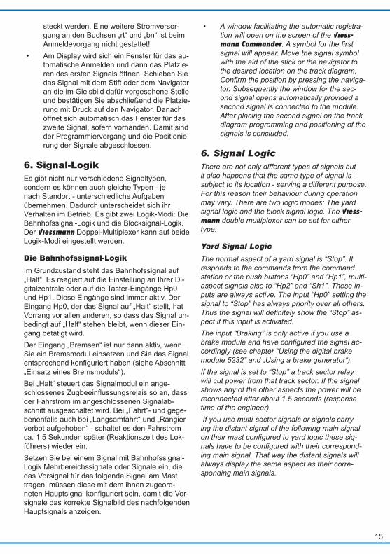
• Am Display wird sich ein Fenster für das au-tomatische Anmelden und dann das Platzie-ren des ersten Signals öffnen. Schieben Sie das Signal mit dem Stift oder dem Navigator an die im Gleisbild dafür vorgesehene Stelle und bestätigen Sie abschließend die Platzie-rung mit Druck auf den Navigator. Danach öffnet sich automatisch das Fenster für das zweite Signal, sofern vorhanden. Damit sind der Programmiervorgang und die Positionie-rung der Signale abgeschlossen.
6. Signal-LogikEs gibt nicht nur verschiedene Signaltypen, sondern es können auch gleiche Typen - je nach Standort - unterschiedliche Aufgaben übernehmen. Dadurch unterscheidet sich ihr Verhalten im Betrieb. Es gibt zwei Logik-Modi: Die Bahnhofssignal-Logik und die Blocksignal-Logik. Der Viessmann Doppel-Multiplexer kann auf beide Logik-Modi eingestellt werden.
Die Bahnhofssignal-LogikIm Grundzustand steht das Bahnhofssignal auf „Halt“. Es reagiert auf die Einstellung an Ihrer Di-gitalzentrale oder auf die Taster-Eingänge Hp0 und Hp1. Diese Eingänge sind immer aktiv. Der Eingang Hp0, der das Signal auf „Halt“ stellt, hat Vorrang vor allen anderen, so dass das Signal un-bedingt auf „Halt“ stehen bleibt, wenn dieser Ein-gang betätigt wird.Der Eingang „Bremsen“ ist nur dann aktiv, wenn Sie ein Bremsmodul einsetzen und Sie das Signal entsprechendkonfigurierthaben(sieheAbschnitt„Einsatz eines Bremsmoduls“).Bei „Halt“ steuert das Signalmodul ein ange-schlossenesZugbeeinflussungsrelaissoan,dassder Fahrstrom im angeschlossenen Signalab-schnitt ausgeschaltet wird. Bei „Fahrt“- und gege-benenfalls auch bei „Langsamfahrt“ und „Rangier-verbot aufgehoben“ - schaltet es den Fahrstrom ca. 1,5 Sekunden später (Reaktionszeit des Lok-führers) wieder ein.Setzen Sie bei einem Signal mit Bahnhofssignal-Logik Mehrbereichssignale oder Signale ein, die das Vorsignal für das folgende Signal am Mast tragen, müssen diese mit dem ihnen zugeord-netenHauptsignalkonfiguriertsein,damitdieVor-signale das korrekte Signalbild des nachfolgenden Hauptsignals anzeigen.
• A window facilitating the automatic registra-tion will open on the screen of the Viess-mann Commander. A symbol for the first signal will appear. Move the signal symbol with the aid of the stick or the navigator to the desired location on the track diagram. Confirm the position by pressing the naviga-tor. Subsequently the window for the sec-ond signal opens automatically provided a second signal is connected to the module. After placing the second signal on the track diagram programming and positioning of the signals is concluded.
6. Signal LogicThere are not only different types of signals but it also happens that the same type of signal is - subject to its location - serving a different purpose. For this reason their behaviour during operation may vary. There are two logic modes: The yard signal logic and the block signal logic. The Viess-mann double multiplexer can be set for either type.
Yard Signal Logic
The normal aspect of a yard signal is “Stop”. It responds to the commands from the command station or the push buttons “Hp0” and “Hp1”, multi-aspect signals also to “Hp2” and “Sh1”. These in-puts are always active. The input “Hp0” setting the signal to “Stop” has always priority over all others. Thus the signal will definitely show the “Stop” as-pect if this input is activated. The input “Braking” is only active if you use a brake module and have configured the signal ac-cordingly (see chapter “Using the digital brake module 5232” and „Using a brake generator“). If the signal is set to “Stop” a track sector relay will cut power from that track sector. If the signal shows any of the other aspects the power will be reconnected after about 1.5 seconds (response time of the engineer). If you use multi-sector signals or signals carry-ing the distant signal of the following main signal on their mast configured to yard logic these sig-nals have to be configured with their correspond-ing main signal. That way the distant signals will always display the same aspect as their corre-sponding main signals.
16
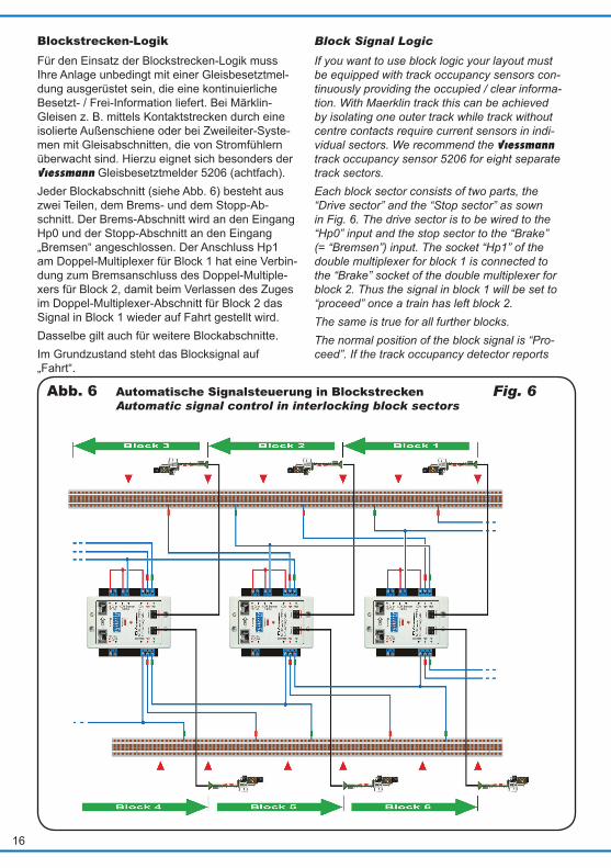
Blockstrecken-LogikFür den Einsatz der Blockstrecken-Logik muss Ihre Anlage unbedingt mit einer Gleisbesetztmel-dung ausgerüstet sein, die eine kontinuierliche Besetzt- / Frei-Information liefert. Bei Märklin-Gleisen z. B. mittels Kontaktstrecken durch eine isolierte Außenschiene oder bei Zweileiter-Syste-men mit Gleisabschnitten, die von Stromfühlern überwacht sind. Hierzu eignet sich besonders der Viessmann Gleisbesetztmelder 5206 (achtfach).Jeder Blockabschnitt (siehe Abb. 6) besteht aus zwei Teilen, dem Brems- und dem Stopp-Ab-schnitt. Der Brems-Abschnitt wird an den Eingang Hp0 und der Stopp-Abschnitt an den Eingang „Bremsen“ angeschlossen. Der Anschluss Hp1 am Doppel-Multiplexer für Block 1 hat eine Verbin-dung zum Bremsanschluss des Doppel-Multiple-xers für Block 2, damit beim Verlassen des Zuges im Doppel-Multiplexer-Abschnitt für Block 2 das Signal in Block 1 wieder auf Fahrt gestellt wird. Dasselbe gilt auch für weitere Blockabschnitte. Im Grundzustand steht das Blocksignal auf „Fahrt“.
Abb. 6 Automatische Signalsteuerung in BlockstreckenAutomatic signal control in interlocking block sectors
Block Signal Logic
If you want to use block logic your layout must be equipped with track occupancy sensors con-tinuously providing the occupied / clear informa-tion. With Maerklin track this can be achieved by isolating one outer track while track without centre contacts require current sensors in indi-vidual sectors. We recommend the Viessmann track occupancy sensor 5206 for eight separate track sectors. Each block sector consists of two parts, the “Drive sector” and the “Stop sector” as sown in Fig. 6. The drive sector is to be wired to the “Hp0” input and the stop sector to the “Brake” (= “Bremsen”) input. The socket “Hp1” of the double multiplexer for block 1 is connected to the “Brake” socket of the double multiplexer for block 2. Thus the signal in block 1 will be set to “proceed” once a train has left block 2. The same is true for all further blocks.The normal position of the block signal is “Pro-ceed”. If the track occupancy detector reports
Fig. 6
17
Co
nfig
Adresse
Signal 2
(Signal 2)
Signal 1
Signal
Viessmann
Mu
ltip
le
xe
r 5
22
92
fr L
ich
tsig
na
le
ü
rt bn Hp1Hp0COM
rtrt bn
Bremsen Hp0 Hp1
16 V ~/ Dig.
16 V ~/ Dig.
LS
B
COM Bremsen
5227
Re
la
is, d
op
pe
lt,
mo
no
sta
bil, 2
x2
UM
viessmann
Fahrabschnitt
Halteabschnit
mind. 1 Zuglänge
mind. 1 Loklänge
Drive section
Stop section
min. 1 train length
min. 1 loco length
1
2
21
rot / red
rot / redrot / red
rot / red
rot / red braun / brown
zu zweitem GleisTo second track
FahrstromTrack power
Meldet der Gleisbesetztmelder über Hp0 einen der folgenden Abschnitte „besetzt“, dann stellt sich das Signal davor automatisch auf „Halt“. Mel-det der Gleisbesetztmelder wieder eine freie Stre-cke, geht das Signal auf „Fahrt“ zurück. Diese automatische Umschaltung auf „Fahrt“ ge-schieht auch dann, wenn z. B. durch Umschalten einer Weiche der Gleisbesetztmelder auf einen anderen Fahrweg umgeleitet wird und dann auf die Besetztmeldungen eines anderen Steuermo-duls reagiert, dessen zugehöriger Streckenab-schnitt frei ist.Im Blockstreckenbetrieb kann die Zentrale die Signalenichtbeeinflussen.
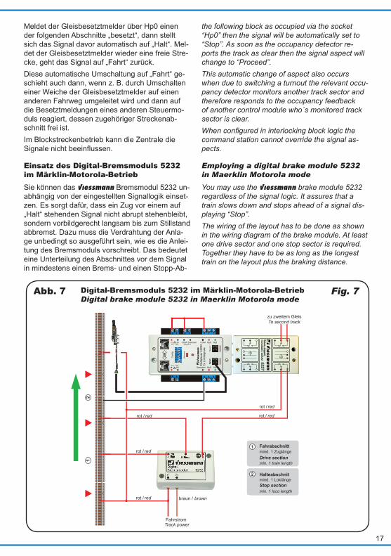
Einsatz des Digital-Bremsmoduls 5232 im Märklin-Motorola-BetriebSie können das Viessmann Bremsmodul 5232 un-abhängig von der eingestellten Signallogik einset-zen. Es sorgt dafür, dass ein Zug vor einem auf „Halt“ stehenden Signal nicht abrupt stehenbleibt, sondern vorbildgerecht langsam bis zum Stillstand abbremst. Dazu muss die Verdrahtung der Anla-ge unbedingt so ausgeführt sein, wie es die Anlei-tung des Bremsmoduls vorschreibt. Das bedeutet eine Unterteilung des Abschnittes vor dem Signal in mindestens einen Brems- und einen Stopp-Ab-
Digital-Bremsmoduls 5232 im Märklin-Motorola-Betrieb Digital brake module 5232 in Maerklin Motorola mode
the following block as occupied via the socket “Hp0” then the signal will be automatically set to “Stop”. As soon as the occupancy detector re-ports the track as clear then the signal aspect will change to “Proceed”. This automatic change of aspect also occurs when due to switching a turnout the relevant occu-pancy detector monitors another track sector and therefore responds to the occupancy feedback of another control module who´s monitored track sector is clear. When configured in interlocking block logic the command station cannot override the signal as-pects.
Employing a digital brake module 5232 in Maerklin Motorola mode
You may use the Viessmann brake module 5232 regardless of the signal logic. It assures that a train slows down and stops ahead of a signal dis-playing “Stop”. The wiring of the layout has to be done as shown in the wiring diagram of the brake module. At least one drive sector and one stop sector is required. Together they have to be as long as the longest train on the layout plus the braking distance.
Fig. 7Abb. 7

18
schnitt. Beide zusammen müssen so lang wie der längste zu erwartende Zug einschließlich des An-halteweges sein.Das Bremsmodul 5232 und eine evtl. erforderliche Gleisbesetztmeldung können gemäß Abb. 7 gleichzeitig an die Gleisabschnitte vor dem Signal angeschlossen werden. Dadurch kann das Bremsmodul sowohl in der Bahnhofs- wie auch der Blocksignallogik eingesetzt werden.Schaltungsbeispiele für den Einsatz des Brems-modulsfindenSieauchinderAnleitungdesDigi-tal-Bremsmoduls 5232.
Einsatz eines Bremsgenerators im DCC-BetriebSie können einen DCC-Bremsgenerator unabhän-gig von der eingestellten Signallogik einsetzen. Der Bremsgenerator sorgt dafür, dass ein Zug vor einem auf „Halt“ stehenden Signal nicht abrupt stehenbleibt, sondern vorbildgerecht langsam bis zum Stillstand abbremst. Dazu muss die Verdrah-tung der Anlage unbedingt so ausgeführt sein, wie es die Anleitung des Bremsgenerators vorschreibt. Normalerweise wird der Abschnitt vor dem Signal in einen Brems- und einen Stopp-Abschnitt un-terteilt. Beide zusammen müssen so lang wie der längste zu erwartende Zug einschließlich des An-halteweges sein. Für die Einleitung des Brems-vorganges ist außerdem ein Kontakt oder eine Gleisbesetztmeldung vorzusehen. Der Doppel-Multiplexer 52292 ist für den Einsatz eines Brems-generators vorbereitet. Haben Sie ihn für den EinsatzeinesBremsgeneratorskonfiguriert,dannsteuertdasModuldasZugbeeinflussungsrelaisbei „Stopp“ nicht sofort an, sondern wartet, bis der Zug den Halteabschnitt erreicht hat.
Hinweis: Kennlicht Das Kennlicht der Ks-Signale leuchtet immer dann, wenn das Signal nicht „grün“ zeigt, da es dann einen verkürzten Abstand zum Vor-signal anzeigt. Verkürzte Abstände zwischen Vor- und Hauptsignalen stellen den Regelfall auf der Modellbahn dar.
Note: marker light The marker light of the Ks signals always lights up when the signal aspect is anything other than “Green”. In that case the signal indicates a shorter than normal distance be-tween distant signal and corresponding main signal. Reduced braking distances between distant signal and main signal are quite nor-mal on model train layouts.
The brake module 5232 and a track occupancy module can be wired to the same track sector at the same time as indicated in Fig. 7. Thus the brake module can also be used regardless of which signal logic is being employed. You find more wiring diagrams in the manual of the Viessmann brake module 5232.
Using a brake generator in DCC mode
You may use the brake generator regardless of the signal logic. The brake generator assures that a train slows down and stops ahead of a signal displaying “Stop”. The wiring of the layout has to be done as shown in the wiring diagram of the brake generator. At least one drive sector and a stop sector are required. Together they have to be as long as the longest train on the layout plus the braking dis-tance. A track contact or track occupancy sensor is re-quired. The double multiplexer 52292 supports the use of a brake generator. Assuming the module is configured for operation with a brake generator and the signal shows the “Stop” aspect then the track control relay will not react immediately but wait until the train has reached the stop sector.

19
Signals suitable for the double multiplexer 52292
Begriff Aspect
BedeutungMeaning
Adresse Address
Eingang Input
Adressen / Addresses
4042 Ks-Einfahrsignal Ks entry signal
Hp0 Halt Stop [B] rot (-) Hp0
Ks1 Fahrt Proceed [B] grün (+) Hp1
Ks1 + Zs3 Fahrt mit x km/h Proceed with x km/h [B+1] grün (+) Hp2
4043 Ks-Ausfahrsignal Ks exit signal
Hp0 Halt Stop [B] rot (-) Hp0
Ks1 Fahrt Proceed [B] grün (+) Hp1
Ks1 + Zs3 Fahrt mit x km/h Proceed with x km/h [B+1] grün (+) Hp2
Sh1 Zughalt, Rangieren erlaubt Stop, shunting permitted [B+1] rot (-) Sh1
4045 Ks-Einfahrsignal (Mehrbereich) Ks entry signal (multi sector)
Hp0 Halt Stop [B] rot (-) Hp0
Ks1 Fahrt Proceed [B] grün (+) Hp1
Ks1 + Zs3 Fahrt mit x km/h Proceed with x km/h [B+1] grün (+) Hp2
Ke Betriebsruhe No traffic [B+3] rot (-) -
4046 Ks-Ausfahrsignal (Mehrbereich) Ks exit signal (multi sector)
Hp0 Halt Stop [B] rot (-) Hp0
Ks1 Fahrt Proceed [B] grün (+) Hp1
Ks1 + Zs3 Fahrt mit x km/h Proceed with x km/h [B+1] grün (+) Hp2
Sh1 Zughalt, Rangieren erlaubt Stop, shunting permitted [B+1] rot (-) Sh1
Ke Betriebsruhe No traffic [B+3] rot (-) -
4721 Blocksignal (Bauart 1969) Block signal (type 1969)
Hp0 Halt Stop [B] rot (-) Hp0
Hp1 Fahrt Proceed [B] grün (+) Hp1
4722 Einfahrsignal (Bauart 1969) Entry signal (type 1969)
Hp0 Halt Stop [B] rot (-) Hp0
Hp1 Fahrt Proceed [B] grün (+) Hp1
Hp2 Langsamfahrt Proceed slowly [B+1] grün (+) Hp2
4723 Ausfahrsignal (Bauart 1969) Exit signal (type 1969)
Hp0 Halt Stop [B] rot (-) Hp0
Hp1 Fahrt Proceed [B] grün (+) Hp1
Hp2 Langsamfahrt Proceed slowly [B+1] grün (+) Hp2
Sh1 Zughalt, Rangieren erlaubt Stop, shunting permitted [B+1] rot (-) Sh1
Mit dem Doppel-Multiplexer 52292 verwendbare Signale
Dieses Produkt ist kein Spielzeug. Nicht geeignet für Kinder unter 14 Jahren! Anleitung aufbewahren!This product is not a toy. Not suitable for children under 14 years! Keep these instructions!Ce produit n’est pas un jouet. Ne convient pas aux enfants de moins de 14 ans ! Conservez ce mode d’emploi !
Dit produkt is geen speelgoed. Niet geschikt voor kin-deren onder 14 jaar! Gebruiksaanwijzing bewaren!Questo prodotto non è un giocattolo. Non adatto a bambini al di sotto dei 14 anni! Conservare instruzi-oni per l’uso!Esto no es un juguete. No recomendado para menores de 14 años! Conserva las instrucciones de servicio!
20
Modellspielwaren GmbH
Begriff Aspect
BedeutungMeaning
Adresse Address
Eingang Input
4724 Blocksignal mit Vorsignal (Bauart 1969) Block signal with distant signal (type 1969)
Hp0 Halt Stop [B] rot (-) Hp0
Hp1 Fahrt Proceed [B] grün (+) Hp1
4725 Einfahrsignal mit Vorsignal (Bauart 1969) Entry signal with distant signal (type 1969)
Hp0 Halt Stop [B] rot (-) Hp0
Hp1 Fahrt Proceed [B] grün (+) Hp1
Hp2 Langsamfahrt Proceed slowly [B+1] grün (+) Hp2
4726 Ausfahrsignal mit Vorsignal (Bauart 1969) Exit signal with distant signal (type 1969)
Hp0 Halt Stop [B] rot (-) Hp0
Hp1 Fahrt Proceed [B] grün (+) Hp1
Hp2 Langsamfahrt Proceed slowly [B+1] grün (+) Hp2
Sh1. Zughalt, Rangieren erlaubt Stop, shunting permitted [B+1] rot (-) Sh1
4727 + 4728 Rangiersignal (Bauart 1969) Stop signal (type 1969)
Sh0 Halt Stop [B] rot (-) Hp0
Sh1 Rangieren erlaubt Shunting permitted [B] grün (+) Sh1
3/2013 ZHStand 01
Sach-Nr. 87588Made in Europe
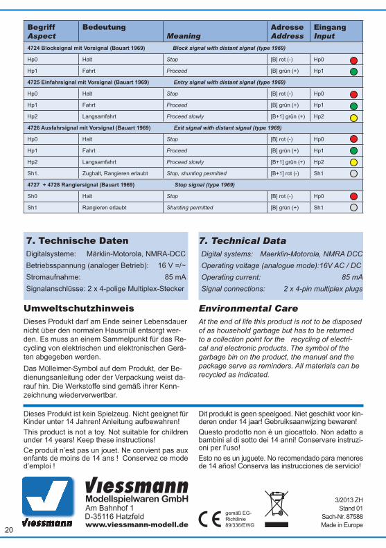
7. Technical DataDigital systems: Maerklin-Motorola, NMRA DCCOperating voltage (analogue mode):16V AC / DCOperating current: 85 mASignal connections: 2 x 4-pin multiplex plugs
Environmental CareAt the end of life this product is not to be disposed of as household garbage but has to be returned to a collection point for the recycling of electri-cal and electronic products. The symbol of the garbage bin on the product, the manual and the package serve as reminders. All materials can be recycled as indicated.
7. Technische DatenDigitalsysteme: Märklin-Motorola, NMRA-DCCBetriebsspannung (analoger Betrieb): 16 V =/~Stromaufnahme: 85 mASignalanschlüsse: 2 x 4-polige Multiplex-Stecker
UmweltschutzhinweisDieses Produkt darf am Ende seiner Lebensdauer nicht über den normalen Hausmüll entsorgt wer-den. Es muss an einem Sammelpunkt für das Re-cycling von elektrischen und elektronischen Gerä-ten abgegeben werden. Das Mülleimer-Symbol auf dem Produkt, der Be-dienungsanleitung oder der Verpackung weist da-rauf hin. Die Werkstoffe sind gemäß ihrer Kenn-zeichnung wiederverwertbar.


![[de] Gebrauchsanleitung](https://static.fdokument.com/doc/165x107/62788e7df6929167c029aaab/de-gebrauchsanleitung.jpg)