
H Labortechnik - analitika.com.tr
84
Planschliffprogramm Flat Flange Programme Programme appareils de rodages plans H W S Labortechnik Saarstraße 52 Entwicklung und Fertigung D 55 122 Mainz Laborkomponenten Postfach 3628 und -systeme aus Glas, D 55 026 Mainz Metall und Kunststoff Telefon: (06131) 37456-0 Meß- und Regeltechnik Telefax: (06131) 30 49 827 Laborelektronik e-mail: [email protected] www.hws-mainz.de
Transcript of H Labortechnik - analitika.com.tr
PlanschliffprogrammFlat Flange Programme
Programme appareils derodages plans
H �W �
S � Labortechnik Saarstraße 52 Entwicklung und Fertigung D 55 122 Mainz Laborkomponenten Postfach 3628 und -systeme aus Glas, D 55 026 Mainz Metall und Kunststoff Telefon: (06131) 37456-0 Meß- und Regeltechnik Telefax: (06131) 30 49 827 Laborelektronik
e-mail: [email protected] www.hws-mainz.de

Unsere Neuheiten HWS-Glasgeräte mit UV-Filter
Die neue Sol-Gel Beschichtung von HWS besteht
aus einer nur µ starken Schicht, die sehr gute
Lichtschutzeigenschaften mit einer verbesserten
Durchsicht verbindet.
Die metallische, blass-
gelbe Schicht ermöglicht
die wesentlich bessere
Beobachtungsmöglichkeit
von chemischen Pro-
zessen, wobei auch farb-
liche Veränderungen
realistisch zu sehen
sind.
Die neue HWS-Sol-Gel-Beschichtung ist auf Wunsch für alle neuen HWS-Geräte als auch
als nachträgliche Beschichtung bereits vorhandener Glasgeräte lieferbar.
HWS-Filtereinheit
Bei vielen chemischen Reaktionen
ist eine abschließende Reinigung
des Produktes bzw. des Produkt-
gemisches notwendig.
Die neue HWS-Filtereinheit
ist fexibel einsetzbar, leicht
zu montieren und demontieren.
So können nun problemlos die
notwendigen Reinigungsschritte
(Filtration) sowohl bei einstufigen
als auch bei mehrstufigen
Prozessen ("on-line")
durchgeführt werden.
Die neue HWS-Filtereinheit
ist auch beim Einsatz von
sauerstoffempfindlichen
Substanzen geeignet.
HWS - KALTGAS-System "COGA'N'für Reaktionsgefäßevon -160°C bis +200 °C
Kaltgas ist ein Temperierungs-
system, das auf der tiefen Tem-
peratur des flüssigen Stickstoffes
als Kältemittel aufbaut.
Der flüssige Stickstoff wird in
einem Kryobehälter mittels
einer Heizung (Jet) verdampft.
Hierdurch wird ein konstanter
tiefkalter Gasstrom erzeugt.
Die hohen Abkühlgeschwindigkeiten
des Mediums im Gefäß werden er-
zeugt durch die hohen Temperatur-
unterschiede zwischen dem Kalt-
gas und dem zu temperierenden
Mediums.
Fordern Sie bei Interesse unseren jeweiligen Prospekt an
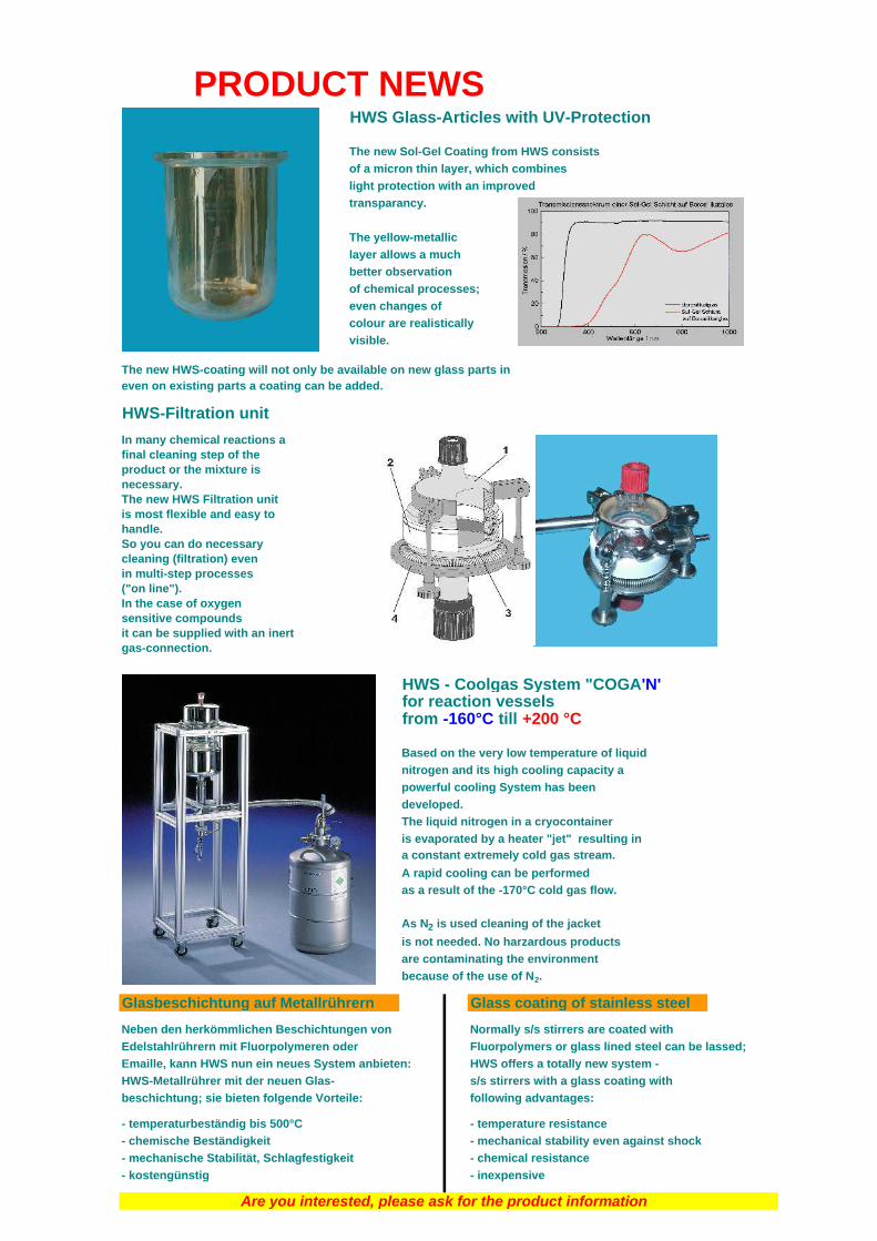
PRODUCT NEWSHWS Glass-Articles with UV-Protection
The new Sol-Gel Coating from HWS consists
of a micron thin layer, which combines
light protection with an improved
transparancy.
The yellow-metallic
layer allows a much
better observation
of chemical processes;
even changes of
colour are realistically
visible.
The new HWS-coating will not only be available on new glass parts ineven on existing parts a coating can be added.
HWS-Filtration unit
In many chemical reactions a final cleaning step of theproduct or the mixture isnecessary.The new HWS Filtration unitis most flexible and easy tohandle.So you can do necessarycleaning (filtration) evenin multi-step processes("on line").In the case of oxygensensitive compoundsit can be supplied with an inertgas-connection.
HWS - Coolgas System "COGA'N'for reaction vesselsfrom -160°C till +200 °C
Based on the very low temperature of liquid
nitrogen and its high cooling capacity a
powerful cooling System has been
developed.
The liquid nitrogen in a cryocontainer
is evaporated by a heater "jet" resulting ina constant extremely cold gas stream.
A rapid cooling can be performed
as a result of the -170°C cold gas flow.
As N2 is used cleaning of the jacket
is not needed. No harzardous products
are contaminating the environment
because of the use of N2.
Glasbeschichtung auf Metallrührern Glass coating of stainless steel
Neben den herkömmlichen Beschichtungen von Normally s/s stirrers are coated with
Edelstahlrührern mit Fluorpolymeren oder Fluorpolymers or glass lined steel can be lassed;
Emaille, kann HWS nun ein neues System anbieten: HWS offers a totally new system -
HWS-Metallrührer mit der neuen Glas- s/s stirrers with a glass coating with
beschichtung; sie bieten folgende Vorteile: following advantages:
- temperaturbeständig bis 500°C - temperature resistance
- chemische Beständigkeit - mechanical stability even against shock
- mechanische Stabilität, Schlagfestigkeit - chemical resistance
- kostengünstig - inexpensive
Are you interested, please ask for the product information
I
H þW þS þDas HWS-Planschliffprogramm läßt Ihnen die freie Wahl
In dem Ihnen nun vorliegenden HWS-Planschliffprogramm haben wir einige gängige Typen (Ausführung und Größe) aufgelistet. Diese Teile sind meistens ab Lager lieferbar.Durch die Lagerhaltung von Standard Halbteilen ist es uns aber natürlich möglich, Ihre Sonderwünsche oder Abänderungen unseres Standardprogrammes schnell und preiswert (z.T. auch aufpreisfrei) zu fertigen. Nehmen Sie Kontakt mit uns auf !Wir haben die wesentlichen Wahlmöglichkeiten mit Ihren verschiedenen Ausführungen nachfolgend aufgelistet. Bitte fügen Sie der Bestell-Nummer des gewählten Artikels einfach den Kennbuchstaben der gewünschten Änderung bei.
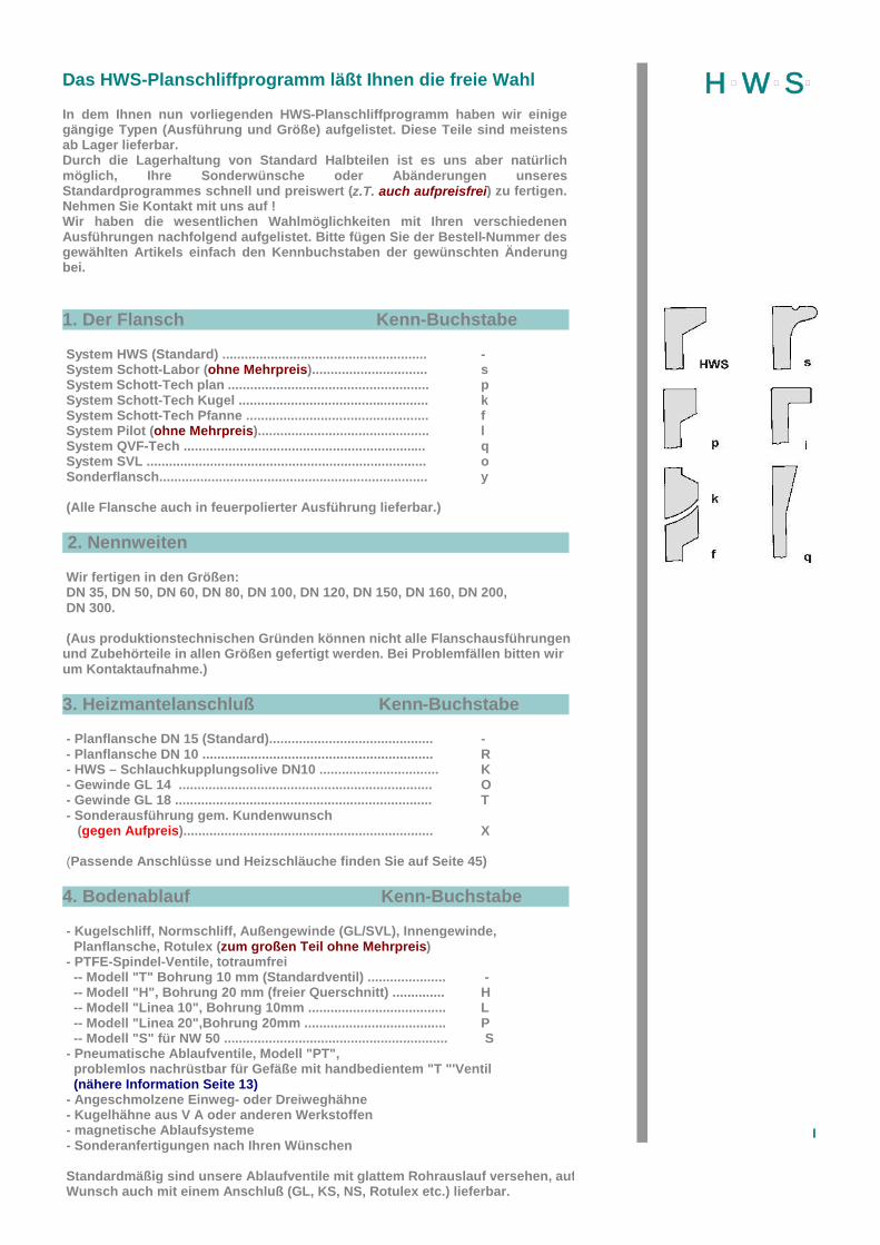
1. Der Flansch Kenn-Buchstabe
System HWS (Standard) ....................................................... - System Schott-Labor (ohne Mehrpreis)............................... s System Schott-Tech plan ...................................................... p System Schott-Tech Kugel ................................................... k System Schott-Tech Pfanne ................................................. f System Pilot (ohne Mehrpreis).............................................. l System QVF-Tech ................................................................. q System SVL ........................................................................... o Sonderflansch........................................................................ y
(Alle Flansche auch in feuerpolierter Ausführung lieferbar.)
2. Nennweiten
Wir fertigen in den Größen: DN 35, DN 50, DN 60, DN 80, DN 100, DN 120, DN 150, DN 160, DN 200, DN 300.
(Aus produktionstechnischen Gründen können nicht alle Flanschausführungen und Zubehörteile in allen Größen gefertigt werden. Bei Problemfällen bitten wir um Kontaktaufnahme.)
3. Heizmantelanschluß Kenn-Buchstabe
- Planflansche DN 15 (Standard)............................................ -- Planflansche DN 10 .............................................................. R- HWS – Schlauchkupplungsolive DN10 ................................ K- Gewinde GL 14 .................................................................... O- Gewinde GL 18 ..................................................................... T- Sonderausführung gem. Kundenwunsch
(gegen Aufpreis)................................................................... X
(Passende Anschlüsse und Heizschläuche finden Sie auf Seite 45)
4. Bodenablauf Kenn-Buchstabe
- Kugelschliff, Normschliff, Außengewinde (GL/SVL), Innengewinde, Planflansche, Rotulex (zum großen Teil ohne Mehrpreis)- PTFE-Spindel-Ventile, totraumfrei
-- Modell "T" Bohrung 10 mm (Standardventil) ..................... --- Modell "H", Bohrung 20 mm (freier Querschnitt) .............. H-- Modell "Linea 10", Bohrung 10mm ..................................... L-- Modell "Linea 20",Bohrung 20mm ...................................... P-- Modell "S" für NW 50 ............................................................ S
- Pneumatische Ablaufventile, Modell "PT", problemlos nachrüstbar für Gefäße mit handbedientem "T "'Ventil (nähere Information Seite 13)- Angeschmolzene Einweg- oder Dreiweghähne- Kugelhähne aus V A oder anderen Werkstoffen- magnetische Ablaufsysteme- Sonderanfertigungen nach Ihren Wünschen
Standardmäßig sind unsere Ablaufventile mit glattem Rohrauslauf versehen, auf Wunsch auch mit einem Anschluß (GL, KS, NS, Rotulex etc.) lieferbar.
II
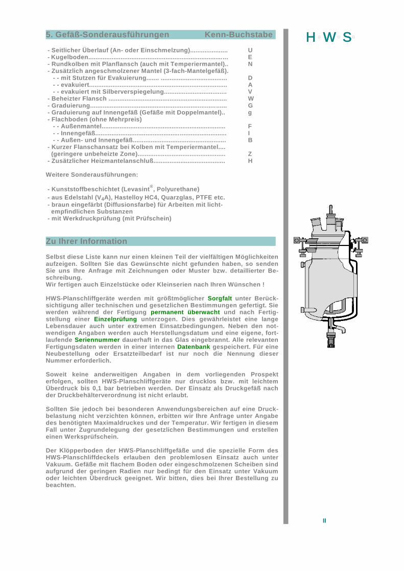
H þW þS þ5. Gefäß-Sonderausführungen Kenn-Buchstabe
- Seitlicher Überlauf (An- oder Einschmelzung)..................... U- Kugelboden.............................................................................. E- Rundkolben mit Planflansch (auch mit Temperiermantel).. N- Zusätzlich angeschmolzener Mantel (3-fach-Mantelgefäß).
- - mit Stutzen für Evakuierung....... ..................................... D- - evakuiert............................................................................. A- - evakuiert mit Silberverspiegelung................................... V
- Beheizter Flansch .................................................................. W- Graduierung...................................................................... ...... G- Graduierung auf Innengefäß (Gefäße mit Doppelmantel).. g- Flachboden (ohne Mehrpreis)
- - Außenmantel..................................................................... F- - Innengefäß......................................................................... I- - Außen- und Innengefäß.................................................... B
- Kurzer Flanschansatz bei Kolben mit Temperiermantel.... (geringere unbeheizte Zone)................................................. Z- Zusätzlicher Heizmantelanschluß........................................ H
Weitere Sonderausführungen:
- Kunststoffbeschichtet (Levasint®, Polyurethane)- aus Edelstahl (V4A), Hastelloy HC4, Quarzglas, PTFE etc.- braun eingefärbt (Diffusionsfarbe) für Arbeiten mit licht-
empfindlichen Substanzen- mit Werkdruckprüfung (mit Prüfschein)
Zu Ihrer Information
Selbst diese Liste kann nur einen kleinen Teil der vielfältigen Möglichkeiten aufzeigen. Sollten Sie das Gewünschte nicht gefunden haben, so senden Sie uns Ihre Anfrage mit Zeichnungen oder Muster bzw. detaillierter Be-schreibung.Wir fertigen auch Einzelstücke oder Kleinserien nach Ihren Wünschen !
HWS-Planschliffgeräte werden mit größtmöglicher Sorgfalt unter Berück-sichtigung aller technischen und gesetzlichen Bestimmungen gefertigt. Sie werden während der Fertigung permanent überwacht und nach Fertig-stellung einer Einzelprüfung unterzogen. Dies gewährleistet eine lange Lebensdauer auch unter extremen Einsatzbedingungen. Neben den not-wendigen Angaben werden auch Herstellungsdatum und eine eigene, fort-laufende Seriennummer dauerhaft in das Glas eingebrannt. Alle relevanten Fertigungsdaten werden in einer internen Datenbank gespeichert. Für eine Neubestellung oder Ersatzteilbedarf ist nur noch die Nennung dieser Nummer erforderlich.
Soweit keine anderweitigen Angaben in dem vorliegenden Prospekt erfolgen, sollten HWS-Planschliffgeräte nur drucklos bzw. mit leichtem Überdruck bis 0,1 bar betrieben werden. Der Einsatz als Druckgefäß nach der Druckbehälterverordnung ist nicht erlaubt.
Sollten Sie jedoch bei besonderen Anwendungsbereichen auf eine Druck-belastung nicht verzichten können, erbitten wir Ihre Anfrage unter Angabe des benötigten Maximaldruckes und der Temperatur. Wir fertigen in diesem Fall unter Zugrundelegung der gesetzlichen Bestimmungen und erstellen einen Werksprüfschein.
Der Klöpperboden der HWS-Planschliffgefäße und die spezielle Form des HWS-Planschliffdeckels erlauben den problemlosen Einsatz auch unter Vakuum. Gefäße mit flachem Boden oder eingeschmolzenen Scheiben sind aufgrund der geringen Radien nur bedingt für den Einsatz unter Vakuum oder leichten Überdruck geeignet. Wir bitten, dies bei Ihrer Bestellung zu beachten.
III
H þW þS þThe HWS-Flat flange program –you are free to choose from various possibilities
The present cataloque present a survey of the more prevalent types of reactors.But we are always anxious to consider alterations and the special wishes of ourcustomers quickly and at a reasonable price.Below you will find a list showing the main options. Please indicate theexecution desired by adding the code letter to the reference number.
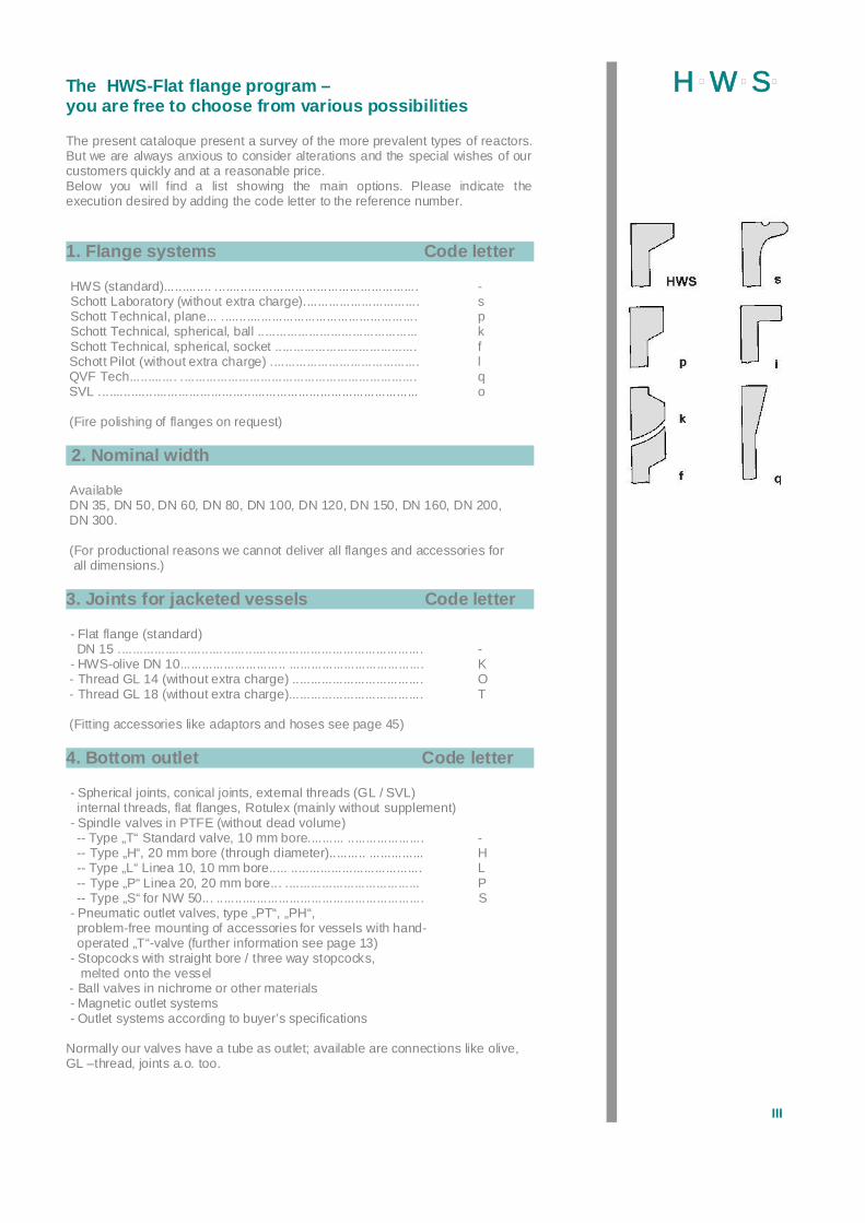
1. Flange systems Code letter
HWS (standard)............. ........................................................ - Schott Laboratory (without extra charge)................................ s Schott Technical, plane... ...................................................... p Schott Technical, spherical, ball ............................................ k Schott Technical, spherical, socket ....................................... f Schott Pilot (without extra charge) ......................................... l QVF Tech............. ................................................................. q SVL ........................................................................................ o
(Fire polishing of flanges on request)
2. Nominal width
Available DN 35, DN 50, DN 60, DN 80, DN 100, DN 120, DN 150, DN 160, DN 200, DN 300.
(For productional reasons we cannot deliver all flanges and accessories for all dimensions.)
3. Joints for jacketed vessels Code letter
- Flat flange (standard) DN 15 .................................................................................... - - HWS-olive DN 10............................. ..................................... K - Thread GL 14 (without extra charge) .................................... O - Thread GL 18 (without extra charge)..................................... T
(Fitting accessories like adaptors and hoses see page 45)
4. Bottom outlet Code letter
- Spherical joints, conical joints, external threads (GL / SVL)internal threads, flat flanges, Rotulex (mainly without supplement)
- Spindle valves in PTFE (without dead volume) -- Type „T“ Standard valve, 10 mm bore.......... ..................... - -- Type „H“, 20 mm bore (through diameter).......... ............... H -- Type „L“ Linea 10, 10 mm bore..... .................................... L -- Type „P“ Linea 20, 20 mm bore... ..................................... P -- Type „S“ for NW 50... ......................................................... S - Pneumatic outlet valves, type „PT“, „PH“,
problem-free mounting of accessories for vessels with hand-operated „T“-valve (further information see page 13)
- Stopcocks with straight bore / three way stopcocks,melted onto the vessel
- Ball valves in nichrome or other materials - Magnetic outlet systems - Outlet systems according to buyer’s specifications
Normally our valves have a tube as outlet; available are connections like olive,GL –thread, joints a.o. too.

IV
H þW þS þ5. Vessels – special models Code letter
- Lateral overflow outlet.......................................................... U - Additional bottom outlet........................................................ B- Round bottom flask with flange ............................................ N - Triplewall vessels - - with socket for evacuation....... ....................................... D - - evacuated........................................................................ A - - evacuated and silver-plated............................................ V - Heated flange ...................................................................... W - Graduation............................................................................ G - Graduation on the inner vessel (for double walled vessel).. g - Flat bottom ( without extra charge) - - Outer bottom.................................................................... F - - Inner bottom..................................................................... I - - Inner and outer bottom..................................................... B - Flange with short neck for jacketed vessels.......................... Z - Additional joints for heating jacket......................................... H
- plastic coated (Levasint, Polyurethane) - in stainless steel, Halar, PTFE - with brown colour for lightsensitive products
Even this list can only show a small part ot the various possibilities.In case you did not find the desired execution/model, please send your inquiryand enclose drafts or samples or detailed description, respectively.We will manufacture small series and even single pieces according to yourrequirement !
Special Information
The HWS flat flange reactor is manufactured with extreme care and precision inorder to comply with all technical requirement and norm regulations. During theproduction all goods are controlled permanently and each finished good is inspec-ted separately. This assures the user that the products has very long life, evenunder extreme operating conditions. Additional to necessary indications we burnin the glass date of manufacture and an uninterrupted number, in order to provideour data bank with essential informations. This code will help you by service,repair cases, or replacements order.
Unless otherwise specified in the prospectus, the HWS flat flange reactor shouldbe implemented without pressure or only under pressure up to 0,1 bar. The use ofthis product as a pressurized reactor in keeping with the relevant norms is notpermissible.However, should your particular application require pressure, please includemaximum pressure and temperature requirements in your inquiry. Your specialorder will then be manufactured based on standard norms and will include amaterial test certificate.The HWS flat flange reactor may also be easily implemented in a vacuumbecause of ist torispherical shape and the special shape of the HWS flat flangelids. When making your order, please note that reactors with a flat bottom or amelted disc having smaller radii can only be used in a vacuum or under slightexcess pressure in limited circumstances.
V
H þW þS þLe programme HWS appareils de rodages plans vouslaisse libre choix
Dans le programme HWS que vous venez de recevoir, vous trouverez une listede quelques modèles courants (type et dimensions). Dans la majorité des casces modèles sont disponibles en stock.Grâce à un stockage de pièces standard semi-produites nous avons bien-sûr lapossibilité de façonner des pièces sur demande spéciale de votre part oud’apporter des modifications à notre programme standard dans les plus brefsdélais et à coût minime (dans certains cas sans majoration de prix). Veuillezprendre contact avec nous!Vous trouverez ci-dessous une liste des modèles les plus courants avec leurstypes différents. Veuillez mentionner outre le numéro de l’article choisi la lettredistinctive correspondant à la modification choisie.
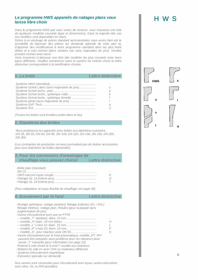
1. La bride Lettre distinctive
Système HWS (standard)....................................................... -Système Schott Labor (sans majoration de prix).................... sSystème Schott techn., plan................................................... pSystème Schott techn., sphérique mâle ................................. kSystème Schott techn., sphérique femelle ........................... fSystème pilote (sans majoration de prix) ............................... lSystème QVF Tech............. .................................................. qSystème SVL ......................................................................... o
(Toutes les brides sont livrables polies dans le feu)
2. Diamètres des brides
Nous produisons les apparails avec brides aux diamètres suivantes: DN 35, DN 50, DN 60, DN 80, DN 100, DN 120, DN 150, DN 160, DN 200, DN 300.
(Les contraintes de production ne nous permettent pas de deliver accessoirespour tous diamètres de brides demandés)
3. Pour les connexions d’enveloppe dechauffage vous pouvez choisir Lettre distinctive
- Bride plan (standard) DN 15 .................................................................................... - - HWS-raccord tuyau souple............................. ...................... K - Filetage GL 14 (même prix)................................................... O - Filetage GL 18 (même prix)................................................... T
(Pour adaptateur et tuyau flexible de chauffage voir page 45)
4. Ecoulement par le fond Lettre distinctive
- Rodage sphérique, rodage standard, filetage extérieur (GL / SVL)filetage intérieur, rodage plan, Rotulex (pour la plupart sansaugmentation de prix)
- Vanne d’écoulement avec axe en PTFE -- modèle „T“ standard, diam. 10 mm.............. ..................... - -- modèle „H“ diam. 20 mm (libre)......................... ............... H -- modèle „L“ Linea 10, diam. 10 mm..................................... L -- modèle „P“ Linea 20, diam. 20 mm... ................................ P -- modèle „S“, pour reacteur avec DN 50... ........................... S - Vanne d’écoulement par le fond pneumatique, modèle „PT, PH“
peuvent être préparée sans problème pour les réacteurs avecvanne „T“ manuelle (pour information voir page 13)
- Robinet à voie droite et à voie-T soudée aux réacteurs - Robinet de vide en acier CrNi ou matériaux différents - Système d’écoulement magnétique - Exécution speciale sur demande
Nos vannes sont construites pour l’écoulement avec tuyau; autres exécutionsavec olive, GL ou RIN possibles.
VI
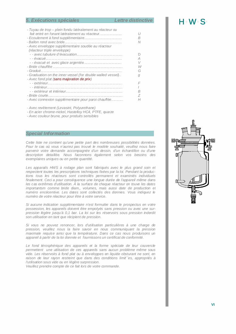
H þW þS þ5. Exécutions spéciales Lettre distinctive
- Tuyau de trop – plein fondu latéralement au réacteur oufait entré en fonant latéralement au réacteur....................... U
- Ecoulement à fond supplémentaire...................................... B - Ballon rond avec bride............. ............................................ N - Avec enveloppe supplémentaire soudée au réacteur (réacteur triple enveloppe) - - avec tubulure d‘évacuation.............................................. D - - évacué............................................................................. A - - évacué et avec glace argentée...................................... V - Bride chauffée ...................................................................... W - Gradué.................................................................................. G - Graduation on the inner vessel (for double walled vessel).. g - Avec fond plat (sans majoration de prix) - - extérieur........................................................................... F - - intérieur............................................................................ I - - extérieur et intérieur......................................................... B - Bride courte........................................................................... Z - Avec connexion supplémentaire pour paroi chauffée............ H
- Avec revêtement (Levasint, Polyurethane) - En acier chrome-nickel, Hastelloy HC4, PTFE, quarze - Avec couleur brune, pour produits sensibles
Special Information
Cette liste ne contient qu’une petite part des nombreuses possibilitiés données.Pour le cas où vous n’auriez pas trouvé le modèle souhaité, veuillez nous faireparvenir votre demande accompagnée d’un dessin, d’un échantillon ou d’unedescription detaillée. Nous faconnons également selon vos besoins desexemplaires uniques ou en petite quantité.
Les apparails HWS à rodage plan sont fabriqués avec le plus grand soin etrespectent toutes les prescriptions techniques fixées par la loi. Pendant la produc-tions tous les réacteurs sont controllés permanent et examiniés individuelsfinalement. Ceci a pour conséquence une longue durée de l’appareil même dansles cas extrêmes d’utilisation. À la surface de chaque réacteur on touve les datesimportantsm comme bride diam., volumes, mais aussi date de production etnuméro encécentive. Les dates sont collectés des donnies. Vous indiquez lenuméro de votre réacteur pour être à votre service.
Si aucune indication supplémentaire n’est formulée dans le prospectus en votrepossession, les appareils doivent être empolyés sans pression ou avec une sur-pression légère jusqu’à 0,1 bar. La loi sur les réservoirs sous pression inderditson utilisation en tant que récipient de pression.
Si vous ne pouvez renoncer, lors d’utilisation particulières à une charge depression, veuillez nous la faire savoir en nous communiquant la pressionmaximale requise ainsi que la température. Dans ce cas nous produisons unappareil à partir de la loi donnée et fournissons un certificat de conformité.
Le fond térosphérique des appareils et la forme spéciale de leur couverclepermettent une utilisation de ces appareils sans aucun problème même sousvide. Les réservoirs à fond plat ou à enveloppes en liquide obsturant ne sont, enraison de leur rayon restreint que dans des conditions limit´´es, appropriés àl’utilisation sous vide ou en légère surpression.Veuillez prendre compte de ce fait lors de votre commande.
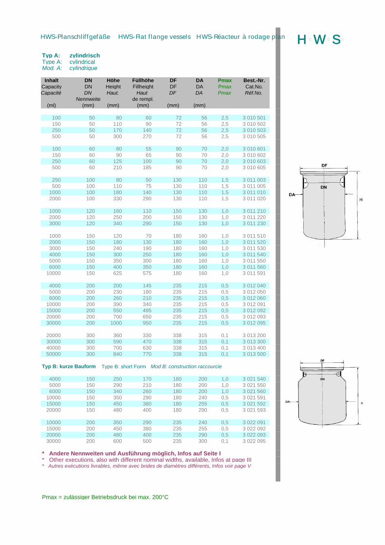
Typ A: zylindrischType A: cylindricalMod. A: cylindrique
Inhalt DN Höhe Füllhöhe DF DA Pmax Best.-Nr.Capacity DN Height Fillheight DF DA Pmax Cat.No.Capacité DN Haut. Haut DF DA Pmax Réf.No.
Nennweite de rempl.(ml) (mm) (mm) (mm) (mm) (mm)
100 50 80 60 72 56 2,5 3 010 501150 50 110 90 72 56 2,5 3 010 502250 50 170 140 72 56 2,5 3 010 503500 50 300 270 72 56 2,5 3 010 505
100 60 80 55 90 70 2,0 3 010 601150 60 90 65 90 70 2,0 3 010 602250 60 125 100 90 70 2,0 3 010 603500 60 210 185 90 70 2,0 3 010 605
250 100 80 50 130 110 1,5 3 011 003500 100 110 75 130 110 1,5 3 011 005
1000 100 180 140 130 110 1,5 3 011 0102000 100 330 290 130 110 1,5 3 011 020
1000 120 160 110 150 130 1,0 3 011 2102000 120 250 200 150 130 1,0 3 011 2203000 120 340 290 150 130 1,0 3 011 230
1000 150 120 70 180 160 1,0 3 011 5102000 150 180 130 180 160 1,0 3 011 5203000 150 240 190 180 160 1,0 3 011 5304000 150 300 250 180 160 1,0 3 011 5405000 150 350 300 180 160 1,0 3 011 5506000 150 400 350 180 160 1,0 3 011 560
10000 150 625 575 180 160 1,0 3 011 591
4000 200 200 145 235 215 0,5 3 012 0405000 200 230 180 235 215 0,5 3 012 0506000 200 260 210 235 215 0,5 3 012 060
10000 200 390 340 235 215 0,5 3 012 09115000 200 550 495 235 215 0,5 3 012 09220000 200 700 650 235 215 0,5 3 012 09330000 200 1000 950 235 215 0,5 3 012 095
20000 300 360 330 338 315 0,1 3 013 20030000 300 590 470 338 315 0,1 3 013 30040000 300 700 630 338 315 0,1 3 013 40050000 300 840 770 338 315 0,1 3 013 500
Typ B: kurze Bauform Type B: short Form Mod B: construction raccourcie
4000 150 250 170 180 200 1,0 3 021 5405000 150 290 210 180 200 1,0 3 021 5506000 150 340 260 180 200 1,0 3 021 560
10000 150 350 290 180 240 0,5 3 021 59115000 150 450 380 180 255 0,5 3 021 59220000 150 480 400 180 290 0,5 3 021 593
10000 200 350 290 235 240 0,5 3 022 09115000 200 450 380 235 255 0,5 3 022 09220000 200 480 400 235 290 0,5 3 022 09330000 200 600 500 235 300 0,1 3 022 095
* Andere Nennweiten und Ausführung möglich, Infos auf Seite I* Other executions, also with different nominal widths, available, Infos at page III* Autres exécutions livrables, même avec brides de diamètres différents, Infos voir page V
Pmax = zulässiger Betriebsdruck bei max. 200°C
H þW þS þHWS-Planschliffgefäße HWS-Flat flange vessels HWS-Réacteur à rodage plan
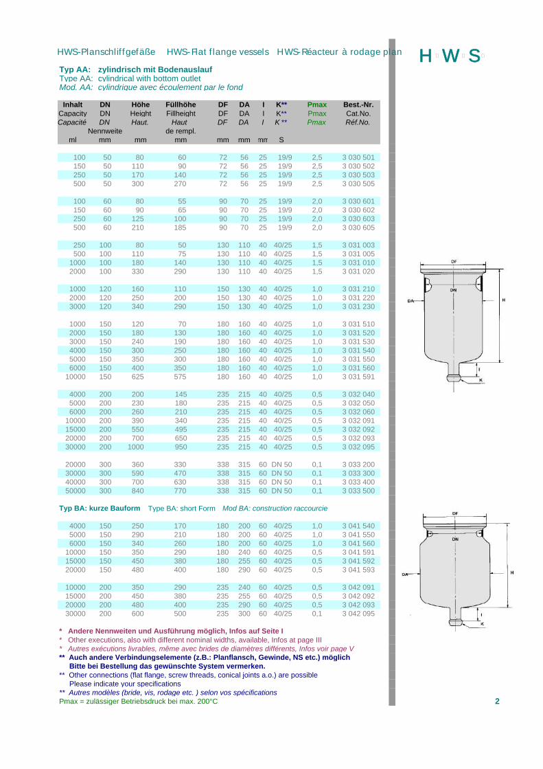
Typ AA: zylindrisch mit BodenauslaufType AA: cylindrical with bottom outletMod. AA: cylindrique avec écoulement par le fond
Inhalt DN Höhe Füllhöhe DF DA I K** Pmax Best.-Nr.Capacity DN Height Fillheight DF DA I K** Pmax Cat.No.Capacité DN Haut. Haut DF DA I K ** Pmax Réf.No.
Nennweite de rempl.ml mm mm mm mm mm mm S
100 50 80 60 72 56 25 19/9 2,5 3 030 501150 50 110 90 72 56 25 19/9 2,5 3 030 502250 50 170 140 72 56 25 19/9 2,5 3 030 503500 50 300 270 72 56 25 19/9 2,5 3 030 505
100 60 80 55 90 70 25 19/9 2,0 3 030 601150 60 90 65 90 70 25 19/9 2,0 3 030 602250 60 125 100 90 70 25 19/9 2,0 3 030 603500 60 210 185 90 70 25 19/9 2,0 3 030 605
250 100 80 50 130 110 40 40/25 1,5 3 031 003500 100 110 75 130 110 40 40/25 1,5 3 031 005
1000 100 180 140 130 110 40 40/25 1,5 3 031 0102000 100 330 290 130 110 40 40/25 1,5 3 031 020
1000 120 160 110 150 130 40 40/25 1,0 3 031 2102000 120 250 200 150 130 40 40/25 1,0 3 031 2203000 120 340 290 150 130 40 40/25 1,0 3 031 230
1000 150 120 70 180 160 40 40/25 1,0 3 031 5102000 150 180 130 180 160 40 40/25 1,0 3 031 5203000 150 240 190 180 160 40 40/25 1,0 3 031 5304000 150 300 250 180 160 40 40/25 1,0 3 031 5405000 150 350 300 180 160 40 40/25 1,0 3 031 5506000 150 400 350 180 160 40 40/25 1,0 3 031 560
10000 150 625 575 180 160 40 40/25 1,0 3 031 591
4000 200 200 145 235 215 40 40/25 0,5 3 032 0405000 200 230 180 235 215 40 40/25 0,5 3 032 0506000 200 260 210 235 215 40 40/25 0,5 3 032 060
10000 200 390 340 235 215 40 40/25 0,5 3 032 09115000 200 550 495 235 215 40 40/25 0,5 3 032 09220000 200 700 650 235 215 40 40/25 0,5 3 032 09330000 200 1000 950 235 215 40 40/25 0,5 3 032 095
20000 300 360 330 338 315 60 DN 50 0,1 3 033 20030000 300 590 470 338 315 60 DN 50 0,1 3 033 30040000 300 700 630 338 315 60 DN 50 0,1 3 033 40050000 300 840 770 338 315 60 DN 50 0,1 3 033 500
Typ BA: kurze Bauform Type BA: short Form Mod BA: construction raccourcie
4000 150 250 170 180 200 60 40/25 1,0 3 041 5405000 150 290 210 180 200 60 40/25 1,0 3 041 5506000 150 340 260 180 200 60 40/25 1,0 3 041 560
10000 150 350 290 180 240 60 40/25 0,5 3 041 59115000 150 450 380 180 255 60 40/25 0,5 3 041 59220000 150 480 400 180 290 60 40/25 0,5 3 041 593
10000 200 350 290 235 240 60 40/25 0,5 3 042 09115000 200 450 380 235 255 60 40/25 0,5 3 042 09220000 200 480 400 235 290 60 40/25 0,5 3 042 09330000 200 600 500 235 300 60 40/25 0,1 3 042 095
* Andere Nennweiten und Ausführung möglich, Infos auf Seite I* Other executions, also with different nominal widths, available, Infos at page III* Autres exécutions livrables, même avec brides de diamètres différents, Infos voir page V** Auch andere Verbindungselemente (z.B.: Planflansch, Gewinde, NS etc.) möglich Bitte bei Bestellung das gewünschte System vermerken.** Other connections (flat flange, screw threads, conical joints a.o.) are possible Please indicate your specifications** Autres modèles (bride, vis, rodage etc. ) selon vos spécificationsPmax = zulässiger Betriebsdruck bei max. 200°C 2
H þW þS þHWS-Planschliffgefäße HWS-Flat flange vessels HWS-Réacteur à rodage plan

Typ AV: zylindrisch mit Bodenauslauf-Ventil***Type AV: cylindrical with bottom outlet valve***Mod. AV: cylindrique avec écoulement par le fond en PTFE ***
Inhalt DN Höhe Füllhöhe DF DA I Pmax Best.-Nr.Capacity DN Height Fillheight DF DA I Pmax Cat.No.Capacité DN Haut. Haut DF DA I Pmax Réf.No.
Nennweite de rempl.ml mm mm mm mm mm mm
100 50 80 60 72 56 55 2,5 3 050 501150 50 110 90 72 56 55 2,5 3 050 502250 50 170 140 72 56 55 2,5 3 050 503500 50 300 270 72 56 55 2,5 3 050 505
100 60 80 55 90 70 75 2,0 3 050 601150 60 90 65 90 70 75 2,0 3 050 602250 60 125 100 90 70 75 2,0 3 050 603500 60 210 185 90 70 75 2,0 3 050 605
250 100 80 50 130 110 75 1,5 3 051 003500 100 110 75 130 110 75 1,5 3 051 005
1000 100 180 140 130 110 75 1,5 3 051 0102000 100 330 290 130 110 75 1,5 3 051 020
1000 120 160 110 150 130 75 1,0 3 051 2102000 120 250 200 150 130 75 1,0 3 051 2203000 120 340 290 150 130 75 1,0 3 051 230
1000 150 120 70 180 160 75 1,0 3 051 5102000 150 180 130 180 160 75 1,0 3 051 5203000 150 240 190 180 160 75 1,0 3 051 5304000 150 300 250 180 160 75 1,0 3 051 5405000 150 350 300 180 160 75 1,0 3 051 5506000 150 400 350 180 160 75 1,0 3 051 560
10000 150 625 575 180 160 75 1,0 3 051 591
4000 200 200 145 235 215 75 0,5 3 052 0405000 200 230 180 235 215 75 0,5 3 052 0506000 200 260 210 235 215 75 0,5 3 052 060
10000 200 390 340 235 215 75 0,5 3 052 09115000 200 550 495 235 215 75 0,5 3 052 09220000 200 700 650 235 215 75 0,5 3 052 09330000 200 1000 950 235 215 75 0,5 3 052 095
20000 300 360 330 338 315 95 0,1 3 053 20030000 300 590 470 338 315 95 0,1 3 053 30040000 300 700 630 338 315 95 0,1 3 053 40050000 300 840 770 338 315 95 0,1 3 053 500
Typ BV: kurze Bauform*** Type BV: short Form*** Mod BV: construction raccourcie ***
4000 150 250 170 180 200 75 1,0 3 061 5405000 150 290 210 180 200 75 1,0 3 061 5506000 150 340 260 180 200 75 1,0 3 061 560
10000 150 350 290 180 240 75 0,5 3 061 59115000 150 450 380 180 255 75 0,5 3 061 59220000 150 480 400 180 290 75 0,5 3 061 593
10000 200 350 290 235 240 75 0,5 3 062 09115000 200 450 380 235 255 75 0,5 3 062 09220000 200 480 400 235 290 75 0,5 3 062 09330000 200 600 500 235 300 75 0,1 3 062 095
*** Standardversion Modell "T" (für DN 60 - DN 200); "H" (für DN 300) andere Ablaufventile, z.B. "H", "L", oder **/PT möglich. Ergänzen Sie bitte Ihre Gefäß-Bestell-Nummer um den Kennbuchstaben des gewünschten Ventils (SeiteI)*** Standard version model "T" (for DN 60 - DN 200); "H" (for DN 300) other models, e.g. "H", "L", or "**/PT" available. Please complete your Cat.No. for the vessel by the code letter of the required valve (page III)*** Modèle standard "T" (pour DN 60 - DN 200); "H" (pour DN 300) autres modèles, par example "H", "L" ou "**/PT" sur demande. Prière de compléter votre Réf.No. du réacteur par la lettre distinctive de la vanne demandée.Pmax = zulässiger Betriebsdruck bei max. 200°C 3
H þW þS þHWS-Planschliffgefäße HWS-Flat flange vessels HWS-Réacteur à rodage plan
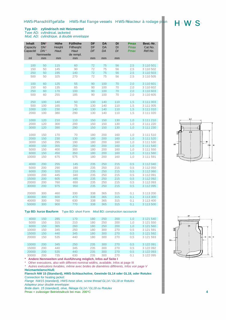
Typ AD: zylindrisch mit HeizmantelType AD: cylindrical, jacketedMod. AD: cylindrique, à double enveloppe
Inhalt DN* Höhe Füllhöhe DF DA DI Pmax Best.-Nr.Capacity DN* Height Fillheight DF DA DI Pmax Cat.No.Capacité DN * Haut. Haut DF DA DI Pmax Réf.No.
Nennweite de rempl.ml mm mm mm mm mm mm
100 50 115 60 72 75 56 2,5 3 110 501150 50 145 90 72 75 56 2,5 3 110 502250 50 195 140 72 75 56 2,5 3 110 503500 50 325 270 72 75 56 2,5 3 110 505
100 60 125 55 90 100 70 2,0 3 110 601150 60 135 65 90 100 70 2,0 3 110 602250 60 170 100 90 100 70 2,0 3 110 603500 60 255 185 90 100 70 2,0 3 110 605
250 100 140 50 130 140 110 1,5 3 111 003500 100 165 75 130 140 110 1,5 3 111 005
1000 100 230 140 130 140 110 1,5 3 111 0102000 100 380 290 130 140 110 1,5 3 111 020
1000 120 210 110 150 150 130 1,0 3 111 2102000 120 300 200 150 150 130 1,0 3 111 2203000 120 390 290 150 150 130 1,0 3 111 230
1000 150 170 70 180 200 160 1,0 3 111 5102000 150 230 130 180 200 160 1,0 3 111 5203000 150 295 190 180 200 160 1,0 3 111 5304000 150 355 250 180 200 160 1,0 3 111 5405000 150 400 300 180 200 160 1,0 3 111 5506000 150 450 350 180 200 160 1,0 3 111 560
10000 150 675 575 180 200 160 1,0 3 111 591
4000 200 255 145 235 250 215 0,5 3 112 0405000 200 290 180 235 250 215 0,5 3 112 0506000 200 320 210 235 250 215 0,5 3 112 060
10000 200 445 340 235 250 215 0,5 3 112 09115000 200 605 495 235 250 215 0,5 3 112 09220000 200 760 650 235 250 215 0,5 3 112 09330000 200 975 950 235 250 215 0,5 3 112 095
20000 300 460 330 338 365 315 0,1 3 113 20030000 300 600 470 338 365 315 0,1 3 113 30040000 300 760 630 338 365 315 0,1 3 113 40050000 300 900 770 338 365 315 0,1 3 113 500
Typ BD: kurze Bauform Type BD: short Form Mod BD: construction raccourcie
4000 150 285 170 180 250 200 1,0 3 121 5405000 150 315 210 180 250 200 1,0 3 121 5506000 150 365 260 180 250 200 1,0 3 121 560
10000 150 345 250 180 300 270 0,5 3 121 59115000 150 440 345 180 300 270 0,5 3 121 59220000 150 535 440 180 300 270 0,5 3 121 593
10000 200 345 250 235 300 270 0,5 3 122 09115000 200 440 345 235 300 270 0,5 3 122 09220000 200 535 440 235 300 270 0,5 3 122 09330000 200 735 630 235 300 270 0,1 3 122 095
* Andere Nennweiten und Ausführung möglich, Infos auf Seite I* Other executions, also with different nominal widths, available, Infos at page III* Autres exécutions livrables, même avec brides de diamètres différents, Infos voir page VHeizmantelanschluß:Flansch NW 15 (Standard), HWS-Schlaucholive, Gewinde GL14 oder GL18, oder RotulexConnection for heating jacket:Flange NW15 (standard), HWS-hose olive, screw thread GL14 / GL18 or RotulexAdapteur pour double enveloppe:Bride diam. 15 (standard), olive, filétage GL14 / GL18 ou RotulexPmax = zulässiger Betriebsdruck bei max. 200°C 4
H þW þS þHWS-Planschliffgefäße HWS-Flat flange vessels HWS-Réacteur à rodage plan
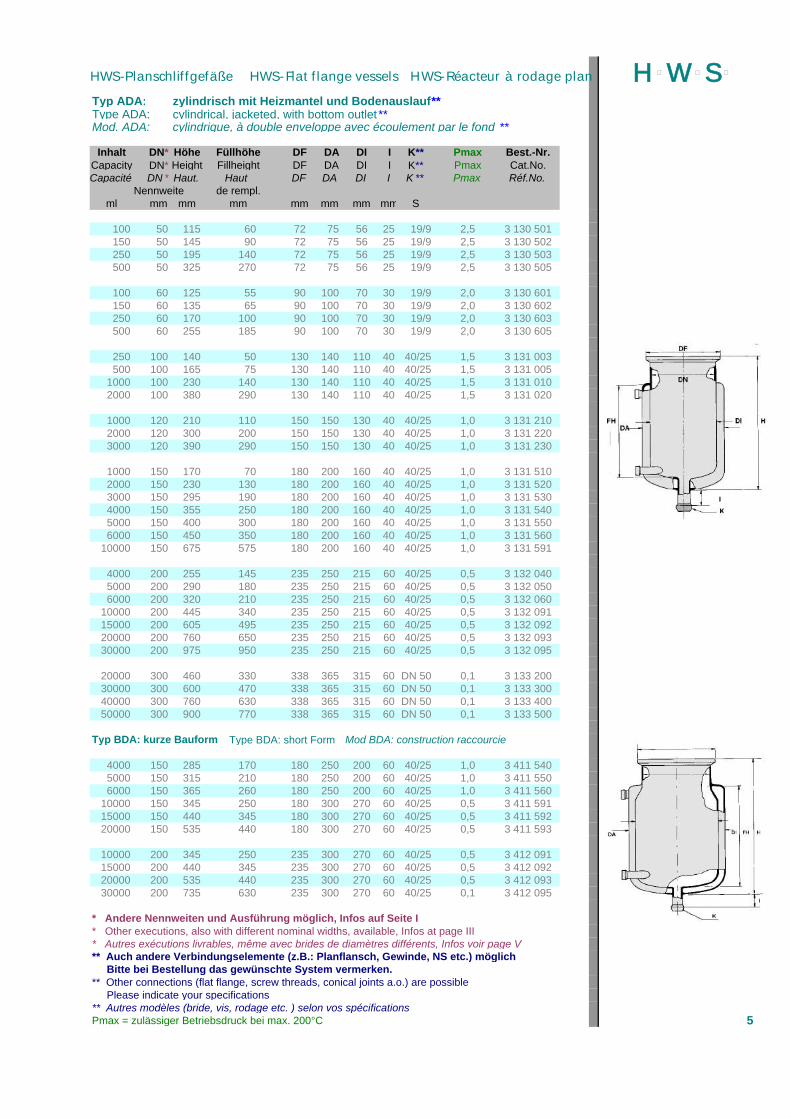
Typ ADA: zylindrisch mit Heizmantel und Bodenauslauf**Type ADA: cylindrical, jacketed, with bottom outlet **Mod. ADA: cylindrique, à double enveloppe avec écoulement par le fond **
Inhalt DN* Höhe Füllhöhe DF DA DI I K** Pmax Best.-Nr.Capacity DN* Height Fillheight DF DA DI I K** Pmax Cat.No.Capacité DN * Haut. Haut DF DA DI I K ** Pmax Réf.No.
Nennweite de rempl.ml mm mm mm mm mm mm mm S
100 50 115 60 72 75 56 25 19/9 2,5 3 130 501150 50 145 90 72 75 56 25 19/9 2,5 3 130 502250 50 195 140 72 75 56 25 19/9 2,5 3 130 503500 50 325 270 72 75 56 25 19/9 2,5 3 130 505
100 60 125 55 90 100 70 30 19/9 2,0 3 130 601150 60 135 65 90 100 70 30 19/9 2,0 3 130 602250 60 170 100 90 100 70 30 19/9 2,0 3 130 603500 60 255 185 90 100 70 30 19/9 2,0 3 130 605
250 100 140 50 130 140 110 40 40/25 1,5 3 131 003500 100 165 75 130 140 110 40 40/25 1,5 3 131 005
1000 100 230 140 130 140 110 40 40/25 1,5 3 131 0102000 100 380 290 130 140 110 40 40/25 1,5 3 131 020
1000 120 210 110 150 150 130 40 40/25 1,0 3 131 2102000 120 300 200 150 150 130 40 40/25 1,0 3 131 2203000 120 390 290 150 150 130 40 40/25 1,0 3 131 230
1000 150 170 70 180 200 160 40 40/25 1,0 3 131 5102000 150 230 130 180 200 160 40 40/25 1,0 3 131 5203000 150 295 190 180 200 160 40 40/25 1,0 3 131 5304000 150 355 250 180 200 160 40 40/25 1,0 3 131 5405000 150 400 300 180 200 160 40 40/25 1,0 3 131 5506000 150 450 350 180 200 160 40 40/25 1,0 3 131 560
10000 150 675 575 180 200 160 40 40/25 1,0 3 131 591
4000 200 255 145 235 250 215 60 40/25 0,5 3 132 0405000 200 290 180 235 250 215 60 40/25 0,5 3 132 0506000 200 320 210 235 250 215 60 40/25 0,5 3 132 060
10000 200 445 340 235 250 215 60 40/25 0,5 3 132 09115000 200 605 495 235 250 215 60 40/25 0,5 3 132 09220000 200 760 650 235 250 215 60 40/25 0,5 3 132 09330000 200 975 950 235 250 215 60 40/25 0,5 3 132 095
20000 300 460 330 338 365 315 60 DN 50 0,1 3 133 20030000 300 600 470 338 365 315 60 DN 50 0,1 3 133 30040000 300 760 630 338 365 315 60 DN 50 0,1 3 133 40050000 300 900 770 338 365 315 60 DN 50 0,1 3 133 500
Typ BDA: kurze Bauform Type BDA: short Form Mod BDA: construction raccourcie
4000 150 285 170 180 250 200 60 40/25 1,0 3 411 5405000 150 315 210 180 250 200 60 40/25 1,0 3 411 5506000 150 365 260 180 250 200 60 40/25 1,0 3 411 560
10000 150 345 250 180 300 270 60 40/25 0,5 3 411 59115000 150 440 345 180 300 270 60 40/25 0,5 3 411 59220000 150 535 440 180 300 270 60 40/25 0,5 3 411 593
10000 200 345 250 235 300 270 60 40/25 0,5 3 412 09115000 200 440 345 235 300 270 60 40/25 0,5 3 412 09220000 200 535 440 235 300 270 60 40/25 0,5 3 412 09330000 200 735 630 235 300 270 60 40/25 0,1 3 412 095
* Andere Nennweiten und Ausführung möglich, Infos auf Seite I* Other executions, also with different nominal widths, available, Infos at page III* Autres exécutions livrables, même avec brides de diamètres différents, Infos voir page V** Auch andere Verbindungselemente (z.B.: Planflansch, Gewinde, NS etc.) möglich Bitte bei Bestellung das gewünschte System vermerken.** Other connections (flat flange, screw threads, conical joints a.o.) are possible Please indicate your specifications** Autres modèles (bride, vis, rodage etc. ) selon vos spécificationsPmax = zulässiger Betriebsdruck bei max. 200°C 5
H þW þS þHWS-Planschliffgefäße HWS-Flat flange vessels HWS-Réacteur à rodage plan
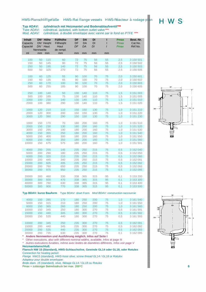
Typ ADAV: zylindrisch mit Heizmantel und Bodenablaufventil***Type ADAV: cylindrical, jacketed, with bottom outlet valve***Mod. ADAV: cylindrique, à double enveloppe avec vanne par le fond en PTFE ***
Inhalt DN* Höhe Füllhöhe DF DA DI I Pmax Best.-Nr.Capacity DN* Height Fillheight DF DA DI I Pmax Cat.No.Capacité DN * Haut. Haut DF DA DI I Pmax Réf.No.
Nennweite de rempl.ml mm mm mm mm mm mm mm
100 50 115 60 72 75 56 55 2,5 3 150 501150 50 145 90 72 75 56 55 2,5 3 150 502250 50 195 140 72 75 56 55 2,5 3 150 503500 50 325 270 72 75 56 55 2,5 3 150 505
100 60 125 55 90 100 70 75 2,0 3 150 601150 60 135 65 90 100 70 75 2,0 3 150 602250 60 170 100 90 100 70 75 2,0 3 150 603500 60 255 185 90 100 70 75 2,0 3 150 605
250 100 140 50 130 140 110 75 1,5 3 151 003500 100 165 75 130 140 110 75 1,5 3 151 005
1000 100 230 140 130 140 110 75 1,5 3 151 0102000 100 380 290 130 140 110 75 1,5 3 151 020
1000 120 210 110 150 150 130 75 1,0 3 151 2102000 120 300 200 150 150 130 75 1,0 3 151 2203000 120 390 290 150 150 130 75 1,0 3 151 230
1000 150 170 70 180 200 160 75 1,0 3 151 5102000 150 230 130 180 200 160 75 1,0 3 151 5203000 150 295 190 180 200 160 75 1,0 3 151 5304000 150 355 250 180 200 160 75 1,0 3 151 5405000 150 400 300 180 200 160 75 1,0 3 151 5506000 150 450 350 180 200 160 75 1,0 3 151 560
10000 150 675 575 180 200 160 75 1,0 3 151 591
4000 200 255 145 235 250 215 75 0,5 3 152 0405000 200 290 180 235 250 215 75 0,5 3 152 0506000 200 320 210 235 250 215 75 0,5 3 152 060
10000 200 445 340 235 250 215 75 0,5 3 152 09115000 200 605 495 235 250 215 75 0,5 3 152 09220000 200 760 650 235 250 215 75 0,5 3 152 09330000 200 975 950 235 250 215 75 0,5 3 152 095
20000 300 460 330 338 365 315 95 0,1 3 153 20030000 300 600 470 338 365 315 95 0,1 3 153 30040000 300 760 630 338 365 315 95 0,1 3 153 40050000 300 900 770 338 365 315 95 0,1 3 153 500
Typ BDAV: kurze Bauform Type BDAV: short Form Mod BDAV: construction raccourcie
4000 150 285 170 180 250 200 75 1,0 3 161 5405000 150 315 210 180 250 200 75 1,0 3 161 5506000 150 365 260 180 250 200 75 1,0 3 161 560
10000 150 345 250 180 300 270 75 0,5 3 161 59115000 150 440 345 180 300 270 75 0,5 3 161 59220000 150 535 440 180 300 270 75 0,5 3 161 593
10000 200 345 250 235 300 270 75 0,5 3 162 09115000 200 440 345 235 300 270 75 0,5 3 162 09220000 200 535 440 235 300 270 75 0,5 3 162 09330000 200 735 630 235 300 270 75 0,1 3 162 095
* Andere Nennweiten und Ausführung möglich, Infos auf Seite I* Other executions, also with different nominal widths, available, Infos at page III* Autres exécutions livrables, même avec brides de diamètres différents, Infos voir page VHeizmantelanschluß:Flansch NW 15 (Standard), HWS-Schlaucholive, Gewinde GL14 oder GL18, oder RotulexConnection for heating jacket:Flange NW15 (standard), HWS-hose olive, screw thread GL14 / GL18 or RotulexAdapteur pour double enveloppe:Bride diam. 15 (standard), olive, filétage GL14 / GL18 ou RotulexPmax = zulässiger Betriebsdruck bei max. 200°C 6
H þW þS þHWS-Planschliffgefäße HWS-Flat flange vessels HWS-Réacteur à rodage plan
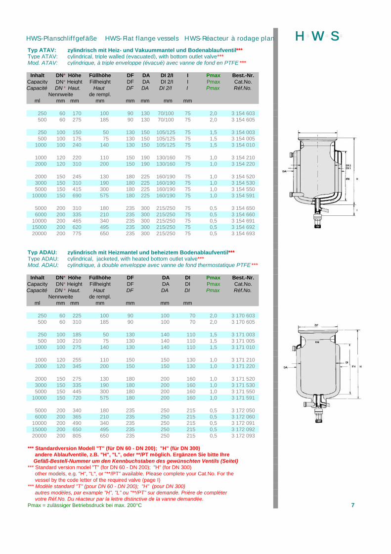
Typ ATAV: zylindrisch mit Heiz- und Vakuummantel und Bodenablaufventil***Type ATAV: cylindrical, triple walled (evacuated), with bottom outlet valve***Mod. ATAV: cylindrique, à triple enveloppe (évacué) avec vanne de fond en PTFE ***
Inhalt DN* Höhe Füllhöhe DF DA DI 2/I I Pmax Best.-Nr.Capacity DN* Height Fillheight DF DA DI 2/I I Pmax Cat.No.Capacité DN * Haut. Haut DF DA DI 2/I I Pmax Réf.No.
Nennweite de rempl.ml mm mm mm mm mm mm mm
250 60 170 100 90 130 70/100 75 2,0 3 154 603500 60 275 185 90 130 70/100 75 2,0 3 154 605
250 100 150 50 130 150 105/125 75 1,5 3 154 003500 100 175 75 130 150 105/125 75 1,5 3 154 005
1000 100 240 140 130 150 105/125 75 1,5 3 154 010
1000 120 220 110 150 190 130/160 75 1,0 3 154 2102000 120 310 200 150 190 130/160 75 1,0 3 154 220
2000 150 245 130 180 225 160/190 75 1,0 3 154 5203000 150 310 190 180 225 160/190 75 1,0 3 154 5305000 150 415 300 180 225 160/190 75 1,0 3 154 550
10000 150 690 575 180 225 160/190 75 1,0 3 154 591
5000 200 310 180 235 300 215/250 75 0,5 3 154 6506000 200 335 210 235 300 215/250 75 0,5 3 154 660
10000 200 465 340 235 300 215/250 75 0,5 3 154 69115000 200 620 495 235 300 215/250 75 0,5 3 154 69220000 200 775 650 235 300 215/250 75 0,5 3 154 693
Typ ADAU: zylindrisch mit Heizmantel und beheiztem Bodenablaufventil***Type ADAU: cylindrical, jacketed, with heated bottom outlet valve***Mod. ADAU: cylindrique, à double enveloppe avec vanne de fond thermostatique PTFE***
Inhalt DN* Höhe Füllhöhe DF DA DI Pmax Best.-Nr.Capacity DN* Height Fillheight DF DA DI Pmax Cat.No.Capacité DN * Haut. Haut DF DA DI Pmax Réf.No.
Nennweite de rempl.ml mm mm mm mm mm mm
250 60 225 100 90 100 70 2,0 3 170 603500 60 310 185 90 100 70 2,0 3 170 605
250 100 185 50 130 140 110 1,5 3 171 003500 100 210 75 130 140 110 1,5 3 171 005
1000 100 275 140 130 140 110 1,5 3 171 010
1000 120 255 110 150 150 130 1,0 3 171 2102000 120 345 200 150 150 130 1,0 3 171 220
2000 150 275 130 180 200 160 1,0 3 171 5203000 150 335 190 180 200 160 1,0 3 171 5305000 150 445 300 180 200 160 1,0 3 171 550
10000 150 720 575 180 200 160 1,0 3 171 591
5000 200 340 180 235 250 215 0,5 3 172 0506000 200 365 210 235 250 215 0,5 3 172 060
10000 200 490 340 235 250 215 0,5 3 172 09115000 200 650 495 235 250 215 0,5 3 172 09220000 200 805 650 235 250 215 0,5 3 172 093
*** Standardversion Modell "T" (für DN 60 - DN 200); "H" (für DN 300) andere Ablaufventile, z.B. "H", "L", oder **/PT möglich. Ergänzen Sie bitte Ihre Gefäß-Bestell-Nummer um den Kennbuchstaben des gewünschten Ventils (SeiteI)*** Standard version model "T" (for DN 60 - DN 200); "H" (for DN 300) other models, e.g. "H", "L", or "**/PT" available. Please complete your Cat.No. For the vessel by the code letter of the required valve (page I)*** Modèle standard "T" (pour DN 60 - DN 200); "H" (pour DN 300) autres modèles, par example "H", "L" ou "**/PT" sur demande. Prière de compléter votre Réf.No. Du réacteur par la lettre distinctive de la vanne demandée.Pmax = zulässiger Betriebsdruck bei max. 200°C 7
H þW þS þHWS-Planschliffgefäße HWS-Flat flange vessels HWS-Réacteur à rodage plan
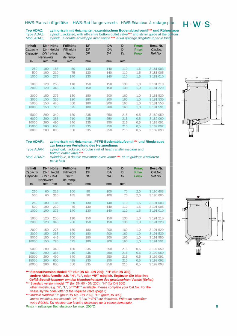
Typ ADAZ: zylindrisch mit Heizmantel, exzentrischem Bodenablaufventil*** und RührerlagerType ADAZ: cylindr., jacketed, with off-centre bottom outlet valve*** and stirrer guide at the bottomMod. ADAZ: cylindr., à double enveloppe avec vanne *** et un guidage d'agitateur par le fond
Inhalt DN* Höhe Füllhöhe DF DA DI Pmax Best.-Nr.Capacity DN* Height Fillheight DF DA DI Pmax Cat.No.Capacité DN * Haut. Haut DF DA DI Pmax Réf.No.
Nennweite de rempl.ml mm mm mm mm mm mm
250 100 185 50 130 140 110 1,5 3 181 003500 100 210 75 130 140 110 1,5 3 181 005
1000 100 275 140 130 140 110 1,5 3 181 010
1000 120 255 110 150 150 130 1,0 3 181 2102000 120 345 200 150 150 130 1,0 3 181 220
2000 150 275 130 180 200 160 1,0 3 181 5203000 150 335 190 180 200 160 1,0 3 181 5305000 150 445 300 180 200 160 1,0 3 181 550
10000 150 720 575 180 200 160 1,0 3 181 591
5000 200 340 180 235 250 215 0,5 3 182 0506000 200 365 210 235 250 215 0,5 3 182 060
10000 200 490 340 235 250 215 0,5 3 182 09115000 200 650 495 235 250 215 0,5 3 182 09220000 200 805 650 235 250 215 0,5 3 182 093
Typ ADAR: zylindrisch mit Heizmantel, PTFE-Bodenablaufventil*** und Ringbrausezur besseren Verteilung des Heizmediums
Type ADAR: cylindrical, jacketed, circular inlet of heat transfer medium andbottom outlet valve ***
Mod. ADAR: cylindrique, à double enveloppe avec vanne*** et un guidage d'agitateurpar le fond
Inhalt DN* Höhe Füllhöhe DF DA DI Pmax Best.-Nr.Capacity DN* Height Fillheight DF DA DI Pmax Cat.No.Capacité DN * Haut. Haut DF DA DI Pmax Réf.No.
Nennweite de rempl.ml mm mm mm mm mm mm
250 60 225 100 90 100 70 2,0 3 190 603500 60 310 185 90 100 70 2,0 3 190 605
250 100 185 50 130 140 110 1,5 3 191 003500 100 210 75 130 140 110 1,5 3 191 005
1000 100 275 140 130 140 110 1,5 3 191 010
1000 120 255 110 150 150 130 1,0 3 191 2102000 120 345 200 150 150 130 1,0 3 191 220
2000 150 275 130 180 200 160 1,0 3 191 5203000 150 335 190 180 200 160 1,0 3 191 5305000 150 445 300 180 200 160 1,0 3 191 550
10000 150 720 575 180 200 160 1,0 3 191 591
5000 200 340 180 235 250 215 0,5 3 192 0506000 200 365 210 235 250 215 0,5 3 192 060
10000 200 490 340 235 250 215 0,5 3 192 09115000 200 650 495 235 250 215 0,5 3 192 09220000 200 805 650 235 250 215 0,5 3 192 093
*** Standardversion Modell "T" (für DN 60 - DN 200); "H" (für DN 300) andere Ablaufventile, z.B. "H", "L", oder **/PT möglich. Ergänzen Sie bitte Ihre Gefäß-Bestell-Nummer um den Kennbuchstaben des gewünschten Ventils (SeiteI)*** Standard version model "T" (for DN 60 - DN 200); "H" (for DN 300) other models, e.g. "H", "L", or "**/PT" available. Please complete your Cat.No. For the vessel by the code letter of the required valve (page I)*** Modèle standard "T" (pour DN 60 - DN 200); "H" (pour DN 300) autres modèles, par example "H", "L" ou "**/PT" sur demande. Prière de compléter votre Réf.No. Du réacteur par la lettre distinctive de la vanne demandée.Pmax = zulässiger Betriebsdruck bei max. 200°C 8
H þW þS þHWS-Planschliffgefäße HWS-Flat flange vessels HWS-Réacteur à rodage plan

Typ KDAV: konisch mit Heizmantel, mit PTFE Bodenablaufventil*** Type KDAV: conical, jacketed, with outlet valve***Mod. KDAV: conique, à double enveloppe avec vanne d'écoulement***
Inhalt DN* Höhe Füllhöhe DF DA DI Pmax Best.-Nr.Capacity DN* Height Fillheight DF DA DI Pmax Cat.No.Capacité DN * Haut. Haut DF DA DI Pmax Réf.No.
Nennweite de rempl. max.Øml mm mm mm mm mm mm
500 100 325 235 130 140 110 1,5 3 158 105750 100 425 335 130 140 110 1,5 3 158 108
1000 100 530 440 130 140 110 1,5 3 158 110
1000 120 380 290 150 160 130 1,0 3 158 2102000 120 635 545 150 160 130 1,0 3 158 220
2000 150 425 325 180 200 160 1,0 3 158 5203000 150 570 470 180 200 160 1,0 3 158 5305000 ** 150 850 750 180 200 160 1,0 3 158 550
** bis 3 ltr. konisch, Rest zylindrisch
Typ KTAV: konisch mit Heiz- und Vakuummantel, mit PTFE Bodenablaufventil*** Type KTAV: conical, triple walled, with outlet valve***MoT. KTAV: conique, à trois parois (évacué) avec vanne d'écoulement ***
Inhalt DN* Höhe Füllhöhe DF DA DI 2/I I Pmax Best.-Nr.Capacity DN* Height Fillheight DF DA DI 2/I I Pmax Cat.No.Capacité DN * Haut. Haut DF DA DI 2/I I Pmax Réf.No.
Nennweite de rempl. max.Øml mm mm mm mm mm mm mm
500 100 325 235 130 140 105/125 75 1,5 3 159 105750 100 425 335 130 140 105/125 75 1,5 3 159 108
1000 100 530 440 130 140 105/125 75 1,5 3 159 110
1000 120 380 290 150 160 130/160 75 1,0 3 159 2102000 120 635 545 150 160 130/160 75 1,0 3 159 220
2000 150 425 325 180 200 160/190 75 1,0 3 159 5203000 150 570 470 180 200 160/190 75 1,0 3 159 5305000 ** 150 850 750 180 200 160/190 75 1,0 3 159 550
** bis 3 ltr. konisch, Rest zylindrisch
* Andere Nennweiten und Ausführung möglich, Infos auf Seite I* Other executions, also with different nominal widths, available, Infos at page III* Autres exécutions livrables, même avec brides de diamètres différents, Infos voir page V
Heizmantelanschluß:Flansch NW 15 (Standard), HWS-Schlaucholive, Gewinde GL14 oder GL18, oder RotulexConnection for heating jacket:Flange NW15 (standard), HWS-hose olive, screw thread GL14 / GL18 or RotulexAdapteur pour double enveloppe:Bride diam. 15 (standard), olive, filétage GL14 / GL18 ou Rotulex
Pmax = zulässiger Betriebsdruck bei max. 200°C 9
H þW þS þHWS-Planschliffgefäße HWS-Flat flange vessels HWS-Réacteur à rodage plan

Modell "T" (Standard für Gefäße mit NW 60 - NW 200)
"T"Model "T" (Standard for NW 60 - NW 200)
Modèle "T" (standard pour réacteurs avec brides diam. 60 - 200 mm)
"K"
Modell "K"Ausführung wie "T", jedoch kurze Bauform, max. Hub 10 mmModel "K"Same as "T", however short form, max. stroke height 10 mmModèle "K"comme modéle "T", mais constr. raccourcie, élév. 10 mm
Modell "H" (Standard für Gefäße mit NW 300)Ausführung wie "T", jedoch mit 20 mm Bohrung, max. Hub 70 mmModel "H" (Standard for NW 300) "H"Same as "T", however, with 20 mm outletModèle "H" (standard pour réacteurs avec brides diam. 300 mm)comme modéle "T", mais avec passage 20 mm
Modell "M"Ausführung wie "H", jedoch kurze Bauform, max. Hub 15 mmModel "M"Same as "H", however short form, max. stroke height 15 mmModèle "M"comme modéle "H", mais constr. Raccourcie, élév. 15 mm
"M"Modell "T/PT"Ausführung wie "T", jedoch mit integriertem PT 100zur problemfreien Messung der Sumpftemperatur auch bei abfließendem MediumModel "T/PT"Same as "T", however with PT 100 sensor in spindlefor the trouble free measurement of temperatureModèle "T/PT"comme modéle "T", mais avec PT 100 en axepour la mesure de température sans problème
Modell "H/PT"Ausführung wie "H", jedoch mit integriertem PT 100 "T/PT"Model "H/PT"Same as "H", however with PT 100 sensor in spindleModèle "H/PT"comme modéle "H", mais avec PT 100 en axe
Modell "S" (Standard für Gefäße mit NW 50)PTFE-Verdrängerventil mit totraumfreier Abdichtung am Gefäßboden,mit 2,5 mm Bohrung, Ventilstift fest mit Gewindekappe verbunden.Model "S" (standard for NW 50)PTFE-valve with 2,5 mm outlet diameterModèle "S" (standard pour réacteurs avec brides diam. 50)PTFE-vanne avec passage 2,5mm
"H/PT"
HWS-Ablaufventile werden standardmäßig mit einem Auslaufwinkel von 30° (Auslauf nach rechts)gefertigt, das Rohrende ist verschmolzen. Auf Wunsch sind natürlich auch andere Winkelaus-Auslaufrichtungen und bearbeitete Enden (z.B.: Gewinde, Rotulex, Kugelschliff, Normschliff, Plan-flansch oder Olive) möglich. Bitte nehmen Sie bei Bedarf Kontakt mit uns auf.
10
H þW þS þ
PTFE-Verdrängerventilspindel mit totraumfreier Abdichtung am Gefäßboden, mit10 mm Bohrung und integrierter Glasablaufschräge, max. Hub 35 mm, mitselbstnachstellendem Spindeldruckpunkt und optischer Verschleißanzeige.Preiswertes Ventil ohne Abstriche an den Sicherheitsfunktionen fürStandardanwendungen mit Flüssigkeiten verschiedener Viskosität. ProblemloserEinsatz eines pneumatischen Ventils oder mit integriertem PT 100 möglich.
PTFE-valve with a minimum of dead-volume, diameter 10 mm, with integrated angleoutlet, for l iquids with varied v iscosity, with integrated spring for spindle for total sealingeven under variable temperature conditions, can be exchanged with pneumatic valvesand valves with integrated PT 100.
Bitte geben Sie dieAnschluß-belegungbzw. Ihren Meß-gerätetyp an
Please indicate type ofconnection or model ofregulator
Indiquez s.v.p.connexion ou modèlede régulateur
PTFE-vanne sans espace mort, passage 10 mm, util isée pour liquide de viscosité var.,avec ressort pour axe, peut être échangé par vanne pneumatique or avec PT 100 enaxe.
HWS-Bodenablaufventile HWS-Bottom outlet valves HWS-vannes de fond
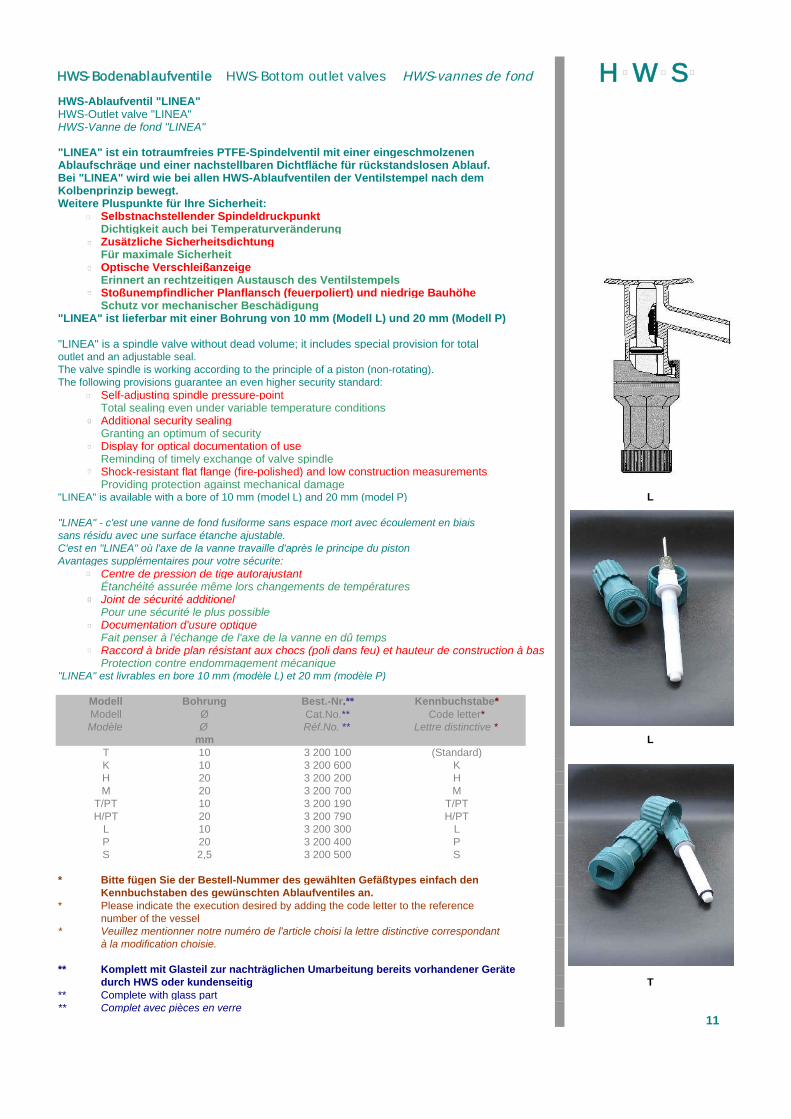
HWS-Ablaufventil "LINEA"HWS-Outlet valve "LINEA"HWS-Vanne de fond "LINEA"
"LINEA" ist ein totraumfreies PTFE-Spindelventil mit einer eingeschmolzenenAblaufschräge und einer nachstellbaren Dichtfläche für rückstandslosen Ablauf.Bei "LINEA" wird wie bei allen HWS-Ablaufventilen der Ventilstempel nach demKolbenprinzip bewegt.Weitere Pluspunkte für Ihre Sicherheit:
Selbstnachstellender SpindeldruckpunktDichtigkeit auch bei TemperaturveränderungZusätzliche SicherheitsdichtungFür maximale SicherheitOptische VerschleißanzeigeErinnert an rechtzeitigen Austausch des VentilstempelsStoßunempfindlicher Planflansch (feuerpoliert) und niedrige BauhöheSchutz vor mechanischer Beschädigung
"LINEA" ist lieferbar mit einer Bohrung von 10 mm (Modell L) und 20 mm (Modell P)
"LINEA" is a spindle valve without dead volume; it includes special provision for totaloutlet and an adjustable seal.The valve spindle is working according to the principle of a piston (non-rotating).The following provisions guarantee an even higher security standard:
Self-adjusting spindle pressure-pointTotal sealing even under variable temperature conditionsAdditional security sealingGranting an optimum of securityDisplay for optical documentation of useReminding of timely exchange of valve spindleShock-resistant flat flange (fire-polished) and low construction measurementsProviding protection against mechanical damage
"LINEA" is available with a bore of 10 mm (model L) and 20 mm (model P) L
"LINEA" - c'est une vanne de fond fusiforme sans espace mort avec écoulement en biaissans résidu avec une surface étanche ajustable. C'est en "LINEA" où l'axe de la vanne travaille d'après le principe du pistonAvantages supplémentaires pour votre sécurite:
Centre de pression de tige autorajustantÉtanchéité assurée même lors changements de températuresJoint de sécurité additionelPour une sécurité le plus possibleDocumentation d'usure optiqueFait penser à l'échange de l'axe de la vanne en dû tempsRaccord à bride plan résistant aux chocs (poli dans feu) et hauteur de construction à basProtection contre endommagement mécanique
"LINEA" est livrables en bore 10 mm (modèle L) et 20 mm (modèle P)
Modell Bohrung Best.-Nr.** Kennbuchstabe*Modell Ø Cat.No.** Code letter*Modèle Ø Réf.No. ** Lettre distinctive *
mm LT 10 3 200 100 (Standard)K 10 3 200 600 KH 20 3 200 200 HM 20 3 200 700 M
T/PT 10 3 200 190 T/PTH/PT 20 3 200 790 H/PT
L 10 3 200 300 LP 20 3 200 400 PS 2,5 3 200 500 S
* Bitte fügen Sie der Bestell-Nummer des gewählten Gefäßtypes einfach denKennbuchstaben des gewünschten Ablaufventiles an.
* Please indicate the execution desired by adding the code letter to the referencenumber of the vessel
* Veuillez mentionner notre numéro de l'article choisi la lettre distinctive correspondantà la modification choisie.
** Komplett mit Glasteil zur nachträglichen Umarbeitung bereits vorhandener Gerätedurch HWS oder kundenseitig T
** Complete with glass part** Complet avec pièces en verre
11
H þW þS þHWS-Bodenablaufventile HWS-Bottom outlet valves HWS-vannes de fond
þ
þ
þ
þ
þ
þ
þ
þ
þ
þ
þ
þ
þ
þ
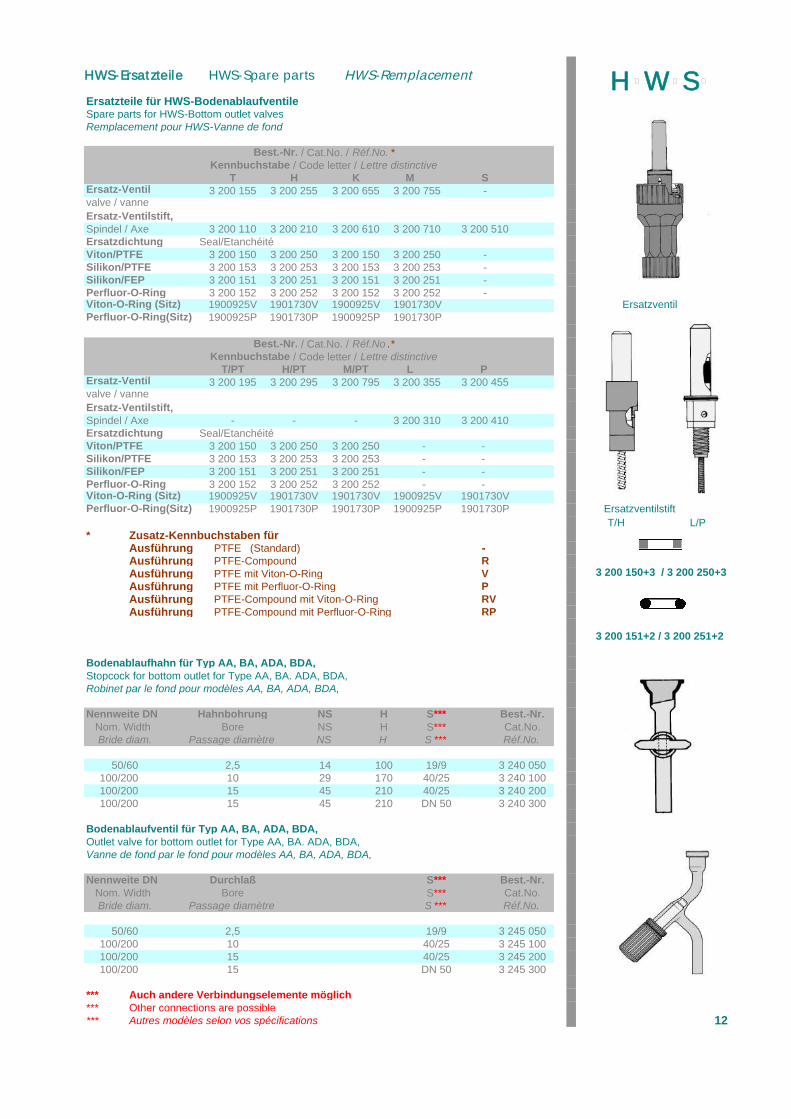
Ersatzteile für HWS-BodenablaufventileSpare parts for HWS-Bottom outlet valvesRemplacement pour HWS-Vanne de fond
Best.-Nr. / Cat.No. / Réf.No. *Kennbuchstabe / Code letter / Lettre distinctive
T H K M SErsatz-Ventil 3 200 155 3 200 255 3 200 655 3 200 755 -valve / vanneErsatz-Ventilstift,Spindel / Axe 3 200 110 3 200 210 3 200 610 3 200 710 3 200 510Ersatzdichtung Seal/EtanchéitéViton/PTFE 3 200 150 3 200 250 3 200 150 3 200 250 -Silikon/PTFE 3 200 153 3 200 253 3 200 153 3 200 253 -Silikon/FEP 3 200 151 3 200 251 3 200 151 3 200 251 -Perfluor-O-Ring 3 200 152 3 200 252 3 200 152 3 200 252 -Viton-O-Ring (Sitz) 1900925V 1901730V 1900925V 1901730V ErsatzventilPerfluor-O-Ring(Sitz) 1900925P 1901730P 1900925P 1901730P
Best.-Nr. / Cat.No. / Réf.No .*Kennbuchstabe / Code letter / Lettre distinctive
T/PT H/PT M/PT L PErsatz-Ventil 3 200 195 3 200 295 3 200 795 3 200 355 3 200 455valve / vanneErsatz-Ventilstift,Spindel / Axe - - - 3 200 310 3 200 410Ersatzdichtung Seal/EtanchéitéViton/PTFE 3 200 150 3 200 250 3 200 250 - -Silikon/PTFE 3 200 153 3 200 253 3 200 253 - -Silikon/FEP 3 200 151 3 200 251 3 200 251 - -Perfluor-O-Ring 3 200 152 3 200 252 3 200 252 - -Viton-O-Ring (Sitz) 1900925V 1901730V 1901730V 1900925V 1901730VPerfluor-O-Ring(Sitz) 1900925P 1901730P 1901730P 1900925P 1901730P Ersatzventilstift
T/H L/P* Zusatz-Kennbuchstaben für
Ausführung PTFE (Standard) -Ausführung PTFE-Compound RAusführung PTFE mit Viton-O-Ring V 3 200 150+3 / 3 200 250+3Ausführung PTFE mit Perfluor-O-Ring PAusführung PTFE-Compound mit Viton-O-Ring RVAusführung PTFE-Compound mit Perfluor-O-Ring RP
3 200 151+2 / 3 200 251+2
Bodenablaufhahn für Typ AA, BA, ADA, BDA,Stopcock for bottom outlet for Type AA, BA. ADA, BDA,Robinet par le fond pour modèles AA, BA, ADA, BDA,
Nennweite DN Hahnbohrung NS H S*** Best.-Nr. Nom. Width Bore NS H S*** Cat.No. Bride diam. Passage diamètre NS H S *** Réf.No.
50/60 2,5 14 100 19/9 3 240 050100/200 10 29 170 40/25 3 240 100100/200 15 45 210 40/25 3 240 200100/200 15 45 210 DN 50 3 240 300
Bodenablaufventil für Typ AA, BA, ADA, BDA,Outlet valve for bottom outlet for Type AA, BA. ADA, BDA,Vanne de fond par le fond pour modèles AA, BA, ADA, BDA,
Nennweite DN Durchlaß S*** Best.-Nr. Nom. Width Bore S*** Cat.No. Bride diam. Passage diamètre S *** Réf.No.
50/60 2,5 19/9 3 245 050100/200 10 40/25 3 245 100100/200 15 40/25 3 245 200100/200 15 DN 50 3 245 300
*** Auch andere Verbindungselemente möglich*** Other connections are possible*** Autres modèles selon vos spécifications 12
H þW þS þHWS-Ersatzteile HWS-Spare parts HWS-Remplacement
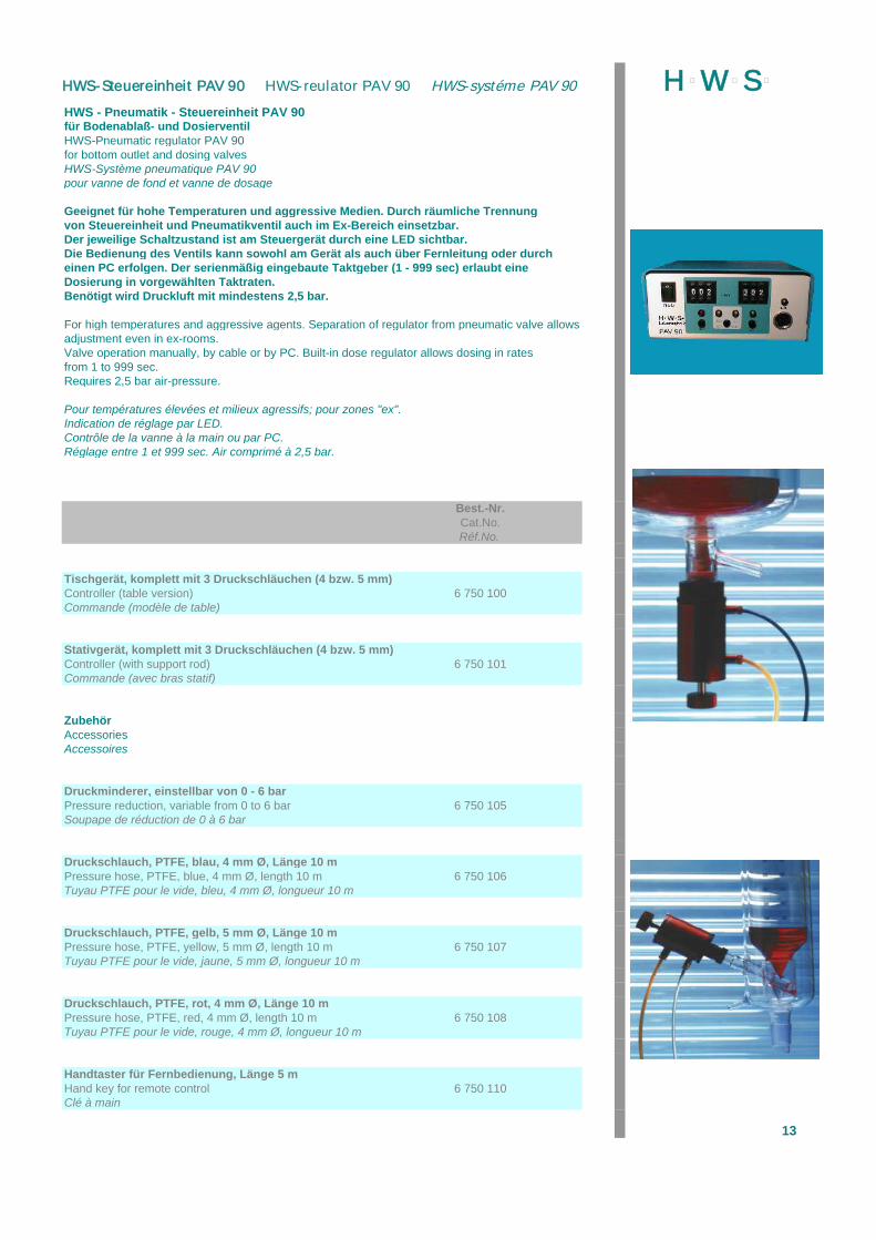
HWS - Pneumatik - Steuereinheit PAV 90für Bodenablaß- und DosierventilHWS-Pneumatic regulator PAV 90for bottom outlet and dosing valvesHWS-Système pneumatique PAV 90pour vanne de fond et vanne de dosage
Geeignet für hohe Temperaturen und aggressive Medien. Durch räumliche Trennungvon Steuereinheit und Pneumatikventil auch im Ex-Bereich einsetzbar.Der jeweilige Schaltzustand ist am Steuergerät durch eine LED sichtbar.Die Bedienung des Ventils kann sowohl am Gerät als auch über Fernleitung oder durcheinen PC erfolgen. Der serienmäßig eingebaute Taktgeber (1 - 999 sec) erlaubt eine Dosierung in vorgewählten Taktraten.Benötigt wird Druckluft mit mindestens 2,5 bar.
For high temperatures and aggressive agents. Separation of regulator from pneumatic valve allowsadjustment even in ex-rooms.Valve operation manually, by cable or by PC. Built-in dose regulator allows dosing in rates from 1 to 999 sec.Requires 2,5 bar air-pressure.
Pour températures élevées et milieux agressifs; pour zones "ex".Indication de réglage par LED.Contrôle de la vanne à la main ou par PC.Réglage entre 1 et 999 sec. Air comprimé à 2,5 bar.
Best.-Nr.Cat.No.Réf.No.
Tischgerät, komplett mit 3 Druckschläuchen (4 bzw. 5 mm)Controller (table version) 6 750 100Commande (modèle de table)
Stativgerät, komplett mit 3 Druckschläuchen (4 bzw. 5 mm)Controller (with support rod) 6 750 101Commande (avec bras statif)
ZubehörAccessoriesAccessoires
Druckminderer, einstellbar von 0 - 6 barPressure reduction, variable from 0 to 6 bar 6 750 105Soupape de réduction de 0 à 6 bar
Druckschlauch, PTFE, blau, 4 mm Ø, Länge 10 mPressure hose, PTFE, blue, 4 mm Ø, length 10 m 6 750 106Tuyau PTFE pour le vide, bleu, 4 mm Ø, longueur 10 m
Druckschlauch, PTFE, gelb, 5 mm Ø, Länge 10 mPressure hose, PTFE, yellow, 5 mm Ø, length 10 m 6 750 107Tuyau PTFE pour le vide, jaune, 5 mm Ø, longueur 10 m
Druckschlauch, PTFE, rot, 4 mm Ø, Länge 10 mPressure hose, PTFE, red, 4 mm Ø, length 10 m 6 750 108Tuyau PTFE pour le vide, rouge, 4 mm Ø, longueur 10 m
Handtaster für Fernbedienung, Länge 5 mHand key for remote control 6 750 110Clé à main
13
H þW þS þHWS-Steuereinheit PAV 90 HWS-reulator PAV 90 HWS-systéme PAV 90
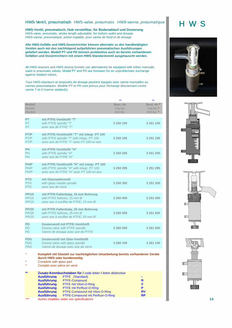
HWS-Ventil, pneumatisch, Hub verstellbar, für Bodenablauf und DosierungHWS-valve, pneumatic, stroke length adjustable, for bottom outlet and dosageHWS-vanne, pneumatique, piston reglable, pour vanne de fond et de dosage
Alle HWS-Gefäße und HWS-Dosiertrichter können alternativ zu den handbetätigtenVentlen auch mit den nachfolgend aufgeführten pneumatischen Ausführungengeliefert werden. Modell PT und PD können problemlos auch an bereits vorhandenenGefäßen und Dosiertrichtern mit einem HWS-Standardventil ausgetauscht werden.
All HWS-reactors and HWS dosing funnels can alternatively be equipped with either manuallyused or pneumatic valves. Model PT and PH are foreseen for an unproblematic exchangeagainst stadard valves.
Tous HWS-réacteurs et ampoules de dosage peutrent èquipés avec vanne manuelles ouvannes pneumatiques. Modèle PT et PH sont prevus pour l'échange directemant contrevanne T et H (vanne stadards).
** **Modell Best.-Nr. Best.-Nr.*Modell Cat.No. Cat.No.*Modèle Réf.No. Réf.No. *
PT mit PTFE-Ventilstift "T"PT with PTFE spindle "T" 3 250 100 3 251 100PT avec axe de PTFE "T"
PT/P mit PTFE-Ventilsstift "T" mit integr. PT 100PT/P with PTFE spindle "T" with integr. PT 100 3 250 195 3 251 195PT/P avec axe de PTFE "T" avec PT 100 en axe
PH mit PTFE-Ventilstift "H"PH with PTFE spindle "H" 3 250 200 3 251 200PH avec axe de PTFE "H"
PH/P mit PTFE-Ventilsstift "H" mit integr. PT 100PH/P with PTFE spindle "H" with integr. PT 100 3 250 295 3 251 295PH/P avec axe de PTFE "H" avec PT 100 en axe
PTG mit GlasnadelventilPTG with glass needle spindle 3 250 300 3 251 300PTG avec axe de verre
PP/15 mit PTFE-Faltenbalg, 15 mm BohrungPP/15 with PTFE bellows, 15 mm Ø 3 250 400 3 251 400PP/15 avec axe à soufflet de PTFE, 15 mm Ø
PP/25 mit PTFE-Faltenbalg, 25 mm BohrungPP/25 with PTFE bellows, 25 mm Ø 3 250 500 3 251 500PP/25 avec axe à soufflet de PTFE, 25 mm Ø
PD Dosierventil mit PTFE-VentilstiftPD Dosing valve with PTFE spindle 3 260 000 3 261 000PD Vanne de dosage avec axe de PTFE
PDG Dosierventil mit Glas-VentilstiftPDG Dosing valve with glass spindle 3 260 100 3 261 100PDG Vanne de dosage avec axe de verre
* Komplett mit Glasteil zur nachträglichen Umarbeitung bereits vorhandener Gerätedurch HWS oder kundenseitig.
* Complete with glass part* Complet avec pièce en verre
** Zusatz-Kennbuchstaben für / code letter / lettre distinctiveAusführung PTFE (Standard) -Ausführung PTFE-Compound RAusführung PTFE mit Viton-O-Ring VAusführung PTFE mit Perfluor-O-Ring PAusführung PTFE-Compound mit Viton-O-Ring RVAusführung PTFE-Compound mit Perfluor-O-Ring RP
*** Autres modèles selon vos spécifications 14
H þW þS þHWS-Ventil, pneumatisch HWS-valve, pneumatic HWS-vanne, pneumatique
HWS-Planschliff-DeckelHWS-Lid flat flangeHWS-Couvercle à rodage plan
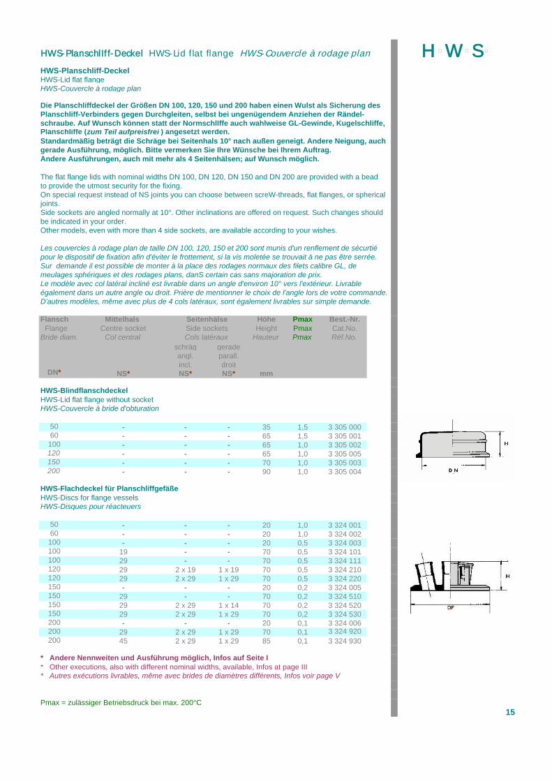
Die Planschliffdeckel der Größen DN 100, 120, 150 und 200 haben einen Wulst als Sicherung desPlanschliff-Verbinders gegen Durchgleiten, selbst bei ungenügendem Anziehen der Rändel-schraube. Auf Wunsch können statt der NormschlIffe auch wahlweise GL-Gewinde, Kugelschliffe,Planschliffe (zum Teil aufpreisfrei ) angesetzt werden.Standardmäßig beträgt die Schräge bei Seitenhals 10° nach außen geneigt. Andere Neigung, auchgerade Ausführung, möglich. Bitte vermerken Sie Ihre Wünsche bei Ihrem Auftrag.Andere Ausführungen, auch mit mehr als 4 Seitenhälsen; auf Wunsch möglich.
The flat flange lids with nominal widths DN 100, DN 120, DN 150 and DN 200 are provided with a beadto provide the utmost security for the fixing.On special request instead of NS joints you can choose between screW-threads, flat flanges, or spherical joints.Side sockets are angled normally at 10°. Other inclinations are offered on request. Such changes should be indicated in your order.Other models, even with more than 4 side sockets, are available according to your wishes.
Les couvercles à rodage plan de taille DN 100, 120, 150 et 200 sont munis d'un renflement de sécurtiépour le dispositif de fixation afin d'éviter le frottement, si la vis moletée se trouvait à ne pas être serrée.Sur demande il est possible de monter à la place des rodages normaux des filets calibre GL, demeulages sphériques et des rodages plans, danS certain cas sans majoration de prix.Le modèle avec col latéral incliné est livrable dans un angle d'environ 10° vers l'extérieur. Livrableégalement dans un autre angle ou droit. Prière de mentionner le choix de l'angle lors de votre commande.D'autres modèles, même avec plus de 4 cols latéraux, sont également livrables sur simple demande.
Flansch Mittelhals Seitenhälse Höhe Pmax Best.-Nr. Flange Centre socket Side sockets Height Pmax Cat.No.Bride diam. Col central Cols latéraux Hauteur Pmax Réf.No.
schräg geradeangl. parall.incl. droit
DN* NS* NS* NS* mm
HWS-BlindflanschdeckelHWS-Lid flat flange without socketHWS-Couvercle à bride d'obturation
50 - - - 35 1,5 3 305 00060 - - - 65 1,5 3 305 001100 - - - 65 1,0 3 305 002120 - - - 65 1,0 3 305 005150 - - - 70 1,0 3 305 003200 - - - 90 1,0 3 305 004
HWS-Flachdeckel für PlanschliffgefäßeHWS-Discs for flange vesselsHWS-Disques pour réacteuers
50 - - - 20 1,0 3 324 00160 - - - 20 1,0 3 324 002100 - - - 20 0,5 3 324 003100 19 - - 70 0,5 3 324 101100 29 - - 70 0,5 3 324 111120 29 2 x 19 1 x 19 70 0,5 3 324 210120 29 2 x 29 1 x 29 70 0,5 3 324 220150 - - - 20 0,2 3 324 005150 29 - - 70 0,2 3 324 510150 29 2 x 29 1 x 14 70 0,2 3 324 520150 29 2 x 29 1 x 29 70 0,2 3 324 530200 - - - 20 0,1 3 324 006200 29 2 x 29 1 x 29 70 0,1 3 324 920200 45 2 x 29 1 x 29 85 0,1 3 324 930
* Andere Nennweiten und Ausführung möglich, Infos auf Seite I* Other executions, also with different nominal widths, available, Infos at page III* Autres exécutions livrables, même avec brides de diamètres différents, Infos voir page V
Pmax = zulässiger Betriebsdruck bei max. 200°C15
H þW þS þHWS-PlanschlIff-Deckel HWS-Lid flat flange HWS-Couvercle à rodage plan
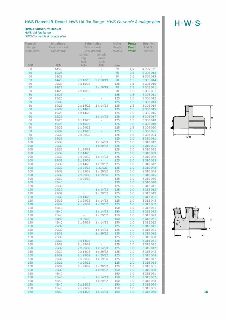
HWS-Planschliff-DeckelHWS-Lid flat flangeHWS-Couvercle à rodage plan
Flansch Mittelhals Seitenhälse Höhe Pmax Best.-Nr. Flange Centre socket Side sockets Height Pmax Cat.No.Bride diam. Col central Cols latéraux Hauteur Pmax Réf.No.
schräg geradeangl. parall.incl. droit
DN* NS* NS* NS* mm50 14/23 - - 70 1,5 3 305 01150 19/26 - - 75 1,5 3 305 01250 29/32 - - 80 1,5 3 305 01350 14/23 2 x 10/19 2 x 10/19 70 1,5 3 305 01450 29/32 2 x 19/26 - 125 1,5 3 305 01550 14/23 - 2 x 10/19 70 1,5 3 305 02150 14/23 2 x 10/19 70 1,5 3 305 03160 14/23 - - 125 1,5 3 306 01160 19/26 - - 125 1,5 3 306 01260 29/32 - - 125 1,5 3 306 01360 19/26 2 x 14/23 1 x 14/23 125 1,5 3 306 01460 29/32 2 x 14/23 - 125 1,5 3 306 01560 19/26 1 x 14/23 - 125 1,5 3 306 01660 19/26 - 1 x 14/23 125 1,5 3 306 01760 19/26 1 x 19/26 - 125 1,5 3 306 01860 19/26 2 x 19/26 - 125 1,5 3 306 01960 29/32 1 x 29/32 - 125 1,5 3 306 02060 29/32 2 x 19/26 - 125 1,5 3 306 02160 29/32 2 x 29/32 - 125 1,5 3 306 024100 29/32 - - 125 1,0 3 310 011100 29/32 - 1 x 14/23 125 1,0 3 310 012100 29/32 - 1 x 29/32 125 1,0 3 310 021100 29/32 1 x 29/32 - 125 1,0 3 310 022100 29/32 1 x 14/23 - 125 1,0 3 310 029100 29/32 1 x 29/32 1 x 14/23 125 1,0 3 310 032100 29/32 2 x 29/32 - 125 1,0 3 310 033100 29/32 2 x 14/23 1 x 29/32 125 1,0 3 310 042100 29/32 2 x 29/32 1 x14/23 125 1,0 3 310 043100 29/32 2 x 29/32 1 x 29/32 125 1,0 3 310 044100 29/32 2 x 29/32 1 x 19/26 125 1,0 3 310 045100 29/32 4 x 29/32 - 125 1,0 3 310 050100 45/40 - - 150 1,0 3 310 070120 29/32 - - 125 1,0 3 312 011120 29/32 - 1 x 14/23 125 1,0 3 312 012120 29/32 - 1 x 29/32 125 1,0 3 312 013120 29/32 2 x 14/23 125 1,0 3 312 031120 29/32 2 x 29/32 1 x 14/23 125 1,0 3 312 043120 29/32 2 x 29/32 1 x 29/32 125 1,0 3 312 052120 45/40 - - 150 1,0 3 312 071120 45/40 - 1 x 14/23 150 1,0 3 312 072120 45/40 - 1 x 29/32 150 1,0 3 312 073120 45(40 2 x 29/32 - 150 1,0 3 312 081120 45/40 2 x 29/32 1 x 14/23 150 1,0 3 312 082150 29/32 - - 125 1,0 3 315 011150 29/32 - 1 x 14/23 125 1,0 3 315 021150 29/32 - 1 x 29/32 125 1,0 3 315 022150 29/32 125 1,0 3 315 030150 29/32 2 x 14/23 - 125 1,0 3 315 031150 29/32 2 x 29/32 - 125 1,0 3 315 032150 29/32 2 x 29/32 1 x 14/23 125 1,0 3 315 042150 29/32 2 x 14/23 1 x 29/32 125 1,0 3 315 043150 29/32 2 x 29/32 1 x 29/32 125 1,0 3 315 044150 29/32 2 x 29/32 1 x 19/26 125 1,0 3 315 047150 29/32 4 x 29/32 - 125 1,0 3 315 053150 29/32 2 x 29/32 2 x 29/32 125 1,0 3 315 051150 29/32 - 4 x 29/32 150 1,0 3 315 050150 45/40 - - 150 1,0 3 315 061150 45/40 - 1 x 14/23 150 1,0 3 315 062150 45/40 - 1 x 29/32 150 1,0 3 315 063150 45/40 2 x 14/23 - 150 1,0 3 315 064150 45/40 2 x 29/32 - 150 1,0 3 315 065150 45/40 2 x 14/23 1 x 14/23 150 1,0 3 315 070 16
H þW þS þHWS-Planschliff-Deckel HWS-Lid flat flange HWS-Couvercle à rodage plan

HWS-Planschliff-DeckelHWS-Lid flat flangeHWS-Couvercle à rodage plan
Flansch Mittelhals Seitenhälse Höhe Pmax Best.-Nr. Flange Centre socket Side sockets Height Pmax Cat.No.Bride diam. Col central Cols latéraux Hauteur Pmax Réf.No.
schräg geradeangl. parall.incl. droit
DN* NS* NS* NS* mm150 45/40 2 x 29/32 1 x 14/23 150 1,0 3 315 074150 45/40 2 x 29/32 1 x 19/26 150 1,0 3 315 075150 45/40 2 x 14/23 1 x 29/32 150 1,0 3 315 076150 45/40 2 x 29/32 1 x 29/32 150 1,0 3 315 077150 45/40 - 4 x 29/32 150 1,0 3 315 078150 45/40 2 x 29/32 2 x 29/32 150 1,0 3 315 109200 29/32 - - 145 1,0 3 320 011200 29/32 - 1 x 14/23 145 1,0 3 320 021200 29/32 2 x 14/23 - 145 1,0 3 320 032200 29/32 - 1 x 29/32 145 1,0 3 320 033200 29/32 2 x 29/32 - 145 1,0 3 320 034200 29/32 1 x 29/32 3 x29/32 145 1,0 3 320 035200 29/32 1 x 14/23 1 x 29/32 145 1,0 3 320 041200 29/32 2 x 29/32 1 x 14/23 145 1,0 3 320 042200 29/32 2 x 29/32 1 x 29/32 145 1,0 3 320 043200 29/32 2 x 29/32 2 x 29/32 145 1,0 3 320 060200 45/40 - - 170 1,0 3 320 051200 45/40 - 1 x 14/23 170 1,0 3 320 052200 45/40 - 1 x 29/32 170 1,0 3 320 053200 45/40 2 x 14/23 - 170 1,0 3 320 054200 45/40 2 x 29/32 - 170 1,0 3 320 055200 45/40 2 x 14/23 1 x 14/23 170 1,0 3 320 056200 45/40 2 x 29/32 1 x 14/23 170 1,0 3 320 057200 45/40 2 x 29/32 1 x 29/32 170 1,0 3 320 058200 45/40 2 x 29/32 2 x 29/32 170 1,0 3 320 107200 45/40 - 4 x 29/32 170 1,0 3 320 059200 45/40 4 x 29/32 - 170 1,0 3 320 114300 45/40 3 x 29/32 1 x 14/23 225 0,1 3 330 010300 45/40 3 x 29/32 2 x 29/32 225 0,1 3 330 015300 45/40 3 x 45/40 2 x 45/40 225 0,1 3 330 801
HWS-Planschliff-Deckel mit PlanflanschhälsenHWS-Lid flat flange with flat flange socketsHWS-Couvercle à rodage plan avec cols de rodages plans
DN* DN DN/NS DN/NS mm100 DN15 2xNS29/32 1xNS14/23 125 1,0 3310143100 DN15 2xNS29/32 1xNS29/32 125 1,0 3310144120 DN15 2xNS29/32 1xNS14/23 125 1,0 3312152120 DN15 2xNS29/32 1xNS29/32 125 1,0 3312153150 DN15 2xNS29/32 1xNS14/23 150 1,0 3315142150 DN15 2xNS29/32 1xNS29/32 150 1,0 3315144150 DN25 2xNS29/32 1xNS14/23 150 1,0 3315174150 DN25 2xNS29/32 1xNS29/32 150 1,0 3315177200 DN25 2xNS29/32 1xNS14/23 170 1,0 3320157200 DN25 2xNS29/32 1xNS29/32 170 1,0 3320158200 DN50 2xDN15 1xDN25 170 1,0 3320170200 DN50 2xDN25 1XDN15 170 1,0 3320175300 DN50 2xDN50 DN25/DN15 225 0,1 3330110300 DN50 DN80/DN50 DN25/DN15 225 0,1 3330115
Alternativ fertigen wir Planschliffdeckel auch aus anderen Materialien (z.B. EdelstahlPTFE, Graphit etc.) mit Normschliff, Gewinde, Stutzen o.Ä. nach Ihren Angaben. Bittenehmen Sie bei Bedarf Kontakt mit uns auf.Other executions in different materials (e.g. stainless steel, PTFE) are available withjoints, screw threads a.o. according your wishes.Autres exécutions livrables avec d'autres matériaux (acier chrome nickel, PTFE)
* Andere Nennweiten und Ausführungen möglich.* Other exécutions, also with different nominal widths, available.* Autres exécutions sont livrables, même avec différents brides diamètres.
* Pmax = zulässiger Betriebsüberdruck bei max. 200° 17
H þW þS þHWS-Planschliff-Deckel HWS-Lid flat flange HWS-Couvercle à rodage plan
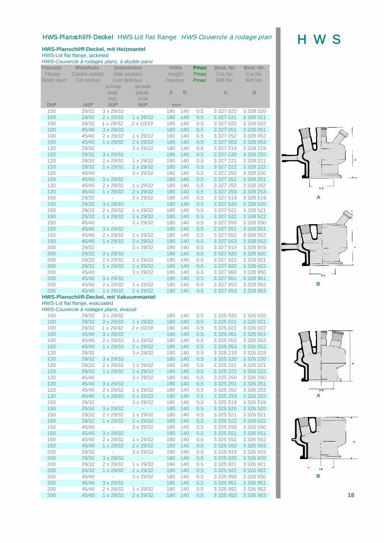
HWS-Planschliff-Deckel, mit HeizmantelHWS-Lid flat flange, jacketedHWS-Couvercle à rodages plans, à double paroiFlansch Mittelhals Seitenhälse Höhe Pmax Best.-Nr. Best.-Nr. Flange Centre socket Side sockets Height Pmax Cat.No. Cat.No.Bride diam. Col central Cols latéraux Hauteur Pmax Réf.No. Réf.No.
schräg geradeangl. parall. A B A Bincl. droit
DN* NS* NS* NS* mm100 29/32 3 x 29/32 - 180 140 0,5 3 327 020 3 328 020100 29/32 2 x 29/32 1 x 29/32 180 140 0,5 3 327 021 3 328 021100 29/32 1 x 29/32 2 x 10/19 180 140 0,5 3 327 022 3 328 022100 45/40 3 x 29/32 - 180 140 0,5 3 327 051 3 328 051100 45/40 2 x 29/32 1 x 29/32 180 140 0,5 3 327 052 3 328 052100 45/40 1 x 29/32 2 x 29/32 180 140 0,5 3 327 053 3 328 053120 29/32 - 3 x 29/32 180 140 0,5 3 327 219 3 328 219120 29/32 3 x 29/32 - 180 140 0,5 3 327 220 3 328 220120 29(32 2 x 29/32 1 x 29/32 180 140 0,5 3 327 221 3 328 221120 29/32 1 x 29/32 2 x 29/32 180 140 0,5 3 327 222 3 328 222120 45/40 - 3 x 29/32 180 140 0,5 3 327 250 3 328 250120 45/40 3 x 29/32 - 180 140 0,5 3 327 251 3 328 251120 45/40 2 x 29/32 1 x 29/32 180 140 0,5 3 327 252 3 328 252120 45/40 1 x 29/32 2 x 29/32 180 140 0,5 3 327 253 3 328 253150 29/32 - 3 x 29/32 180 140 0,5 3 327 519 3 328 519 A150 29/32 3 x 29/32 - 180 140 0,5 3 327 520 3 328 520150 29(32 2 x 29/32 1 x 29/32 180 140 0,5 3 327 521 3 328 521150 29/32 1 x 29/32 2 x 29/32 180 140 0,5 3 327 522 3 328 522150 45/40 - 3 x 29/32 180 140 0,5 3 327 550 3 328 550150 45/40 3 x 29/32 - 180 140 0,5 3 327 551 3 328 551150 45/40 2 x 29/32 1 x 29/32 180 140 0,5 3 327 552 3 328 552150 45/40 1 x 29/32 2 x 29/32 180 140 0,5 3 327 553 3 328 553200 29/32 - 3 x 29/32 180 140 0,5 3 327 919 3 328 919200 29/32 3 x 29/32 - 180 140 0,5 3 327 920 3 328 920200 29(32 2 x 29/32 1 x 29/32 180 140 0,5 3 327 921 3 328 921200 29/32 1 x 29/32 2 x 29/32 180 140 0,5 3 327 922 3 328 922200 45/40 - 3 x 29/32 180 140 0,5 3 327 950 3 328 950200 45/40 3 x 29/32 - 180 140 0,5 3 327 951 3 328 951200 45/40 2 x 29/32 1 x 29/32 180 140 0,5 3 327 952 3 328 952 B200 45/40 1 x 29/32 2 x 29/32 180 140 0,5 3 327 953 3 328 953
HWS-Planschliff-Deckel, mit VakuummantelHWS-Lid flat flange, evacuatedHWS-Couvercle à rodages plans, évacué
100 29/32 3 x 29/32 - 180 140 0,5 3 325 020 3 326 020100 29/32 2 x 29/32 1 x 29/32 180 140 0,5 3 325 021 3 326 021100 29/32 1 x 29/32 2 x 10/19 180 140 0,5 3 325 022 3 326 022100 45/40 3 x 29/32 - 180 140 0,5 3 325 051 3 326 051100 45/40 2 x 29/32 1 x 29/32 180 140 0,5 3 325 052 3 326 052100 45/40 1 x 29/32 2 x 29/32 180 140 0,5 3 325 053 3 326 053120 29/32 - 3 x 29/32 180 140 0,5 3 325 219 3 326 219120 29/32 3 x 29/32 - 180 140 0,5 3 325 220 3 326 220120 29(32 2 x 29/32 1 x 29/32 180 140 0,5 3 325 221 3 326 221120 29/32 1 x 29/32 2 x 29/32 180 140 0,5 3 325 222 3 326 222120 45/40 - 3 x 29/32 180 140 0,5 3 325 250 3 326 250120 45/40 3 x 29/32 - 180 140 0,5 3 325 251 3 326 251120 45/40 2 x 29/32 1 x 29/32 180 140 0,5 3 325 252 3 326 252120 45/40 1 x 29/32 2 x 29/32 180 140 0,5 3 325 253 3 326 253 A150 29/32 - 3 x 29/32 180 140 0,5 3 325 519 3 326 519150 29/32 3 x 29/32 - 180 140 0,5 3 325 520 3 326 520150 29(32 2 x 29/32 1 x 29/32 180 140 0,5 3 325 521 3 326 521150 29/32 1 x 29/32 2 x 29/32 180 140 0,5 3 325 522 3 326 522150 45/40 - 3 x 29/32 180 140 0,5 3 325 550 3 326 550150 45/40 3 x 29/32 - 180 140 0,5 3 325 551 3 326 551150 45/40 2 x 29/32 1 x 29/32 180 140 0,5 3 325 552 3 326 552150 45/40 1 x 29/32 2 x 29/32 180 140 0,5 3 325 553 3 326 553200 29/32 - 3 x 29/32 180 140 0,5 3 325 919 3 326 919200 29/32 3 x 29/32 - 180 140 0,5 3 325 920 3 326 920200 29(32 2 x 29/32 1 x 29/32 180 140 0,5 3 325 921 3 326 921200 29/32 1 x 29/32 2 x 29/32 180 140 0,5 3 325 922 3 326 922200 45/40 - 3 x 29/32 180 140 0,5 3 325 950 3 326 950 B200 45/40 3 x 29/32 - 180 140 0,5 3 325 951 3 326 951200 45/40 2 x 29/32 1 x 29/32 180 140 0,5 3 325 952 3 326 952200 45/40 1 x 29/32 2 x 29/32 180 140 0,5 3 325 953 3 326 953 18
H þW þS þHWS-Planschliff-Deckel HWS-Lid flat flange HWS-Couvercle à rodage plan

HWS-Planschliff-Dichtung*HWS seal for flat flange vessels *HWS-Joint pour rodages plan *
bestehend aus PTFE-Stützring und Dichtungs-O-Ringconsists of a PTFE supporting ring and a seal O-Ringse composant d'une bague d'appui en tissu de verre imprègné de PTFE et d'untorique d'étanchéité
Nennweite O-Ring Ø Höhe Best.-Nr.Nom. Width Diam. height Cat.No.Bride diam. Diam. hauteur Réf.No.
DN mm mm
50 5 4 3 330 5**60 5 4 3 330 6**100 5 4 3 331 0**120 5 4 3 331 2**150 5 4 3 331 5**200 5 4 3 332 0**
Ersatz-O-Ring*Spare-O-ringes*Joints torique de remplacement *
Nennweite O-Ring Ø Best.-Nr.Nom. Width Diam. Cat.No.Bride diam. Diam. Réf.No.
DN mm
50 5 3 340 5**60 5 3 340 6**100 5 3 341 0**120 5 3 341 2**150 5 3 341 5**200 5 3 342 0**
O-Ringe* für Planschliff nach DIN, mit Nut, System "s"O-Rings* for flat flange vessels with groove "s"Joint-O * pour rodage plan avec rainure "s"
Nennweite O-Ring Ø Best.-Nr.Nom. Width Diam. Cat.No.Bride diam. Diam. Réf.No.
DN mm
35 3 3 350 5**60 4 3 350 6**100 4 3 351 0**120 5 3 351 2**150 5 3 351 5**200 5 3 352 0**
* lieferbar in der Ausführung ** Zusatz zur Best.-Nr.* available in ** Addition to Cat.No.* livrable en ** Ajoutez au Réf.No.
VitonViton ......01VitonSilikonSilicone ......03SiliconeSilikon/FEP ummantelt, nahtlosSilicone/FEP coated, seamless ......12Silicone/FEP, sans soudure
19
H þW þS þHWS-Planschliff-Dichtung HWS-Seal HWS-Joint

HWS-Planschliff-Dichtung, graphitiert, für hohe TemperaturenHWS-Flat flange vessel gasket, graphitized, for high temperaturesHWS-Joint pour rodage plan, graphité, pour températures élevées
Nennweite DN Best.-Nr. Nom. Width Cat.No. Bride. Diam. Réf.No.
10 3 360 01015 3 360 01525 3 360 02550 3 360 05060 3 360 060100 3 360 100120 3 360 120150 3 360 150200 3 360 200300 3 360 300
HWS-Planschliff-Flachdichtung aus PTFEHWS-Flat flange vessel gasket inPTFEHWS-Joint pour rodage plan de PTFE
Nennweite DN Best.-Nr. Nom. Width Cat.No. Bride. Diam. Réf.No.
50 3 364 05060 3 364 060100 3 364 100120 3 364 120150 3 364 150200 3 364 200300 3 364 300
HWS-Planschliff-Kammdichtung aus PTFEHWS-Flat flange seal with groove, PTFEHWS-Rondelle d'étanchéité avec rainure, de PTFE
Ausführung "HWS" "Schott" "Tech"Nennweite DN Best.-Nr. Best.-Nr. Best.-Nr. Nom. Width Cat.No. Cat.No. Cat.No. Bride. Diam. Réf.No. Réf.No. Réf.No.
10 3 375 010 - 3 375 01015 3 375 015 - 3 375 01525 3 375 025 - 3 375 02540 - - 3 377 04050 3 375 050 - 3 377 05060 3 375 060 3 376 061 -80 - - 3 377 080100 3 375 100 3 376 101 3 377 100120 3 375 120 3 376 121 -150 3 375 150 3 376 151 3 377 150200 3 375 200 3 376 201 3 377 200300 3 375 300 - 3 377 300
HWS-PTFE/Silikon Stulpendichtung, für MetalladapterHWS-PTFE/silicone seal for HS metal adapterHWS-PTFE/silicone joint plat avec insert pour HWS raccord, metal
Nennweite DN Best.-Nr. Nom. Width Cat.No. Bride. Diam. Réf.No.
10 3 387 11015 3 387 11525 3 387 125
20
H þW þS þHWS-Planschliff-Deckel HWS-Lid flat flange HWS-Couvercle à rodage plan
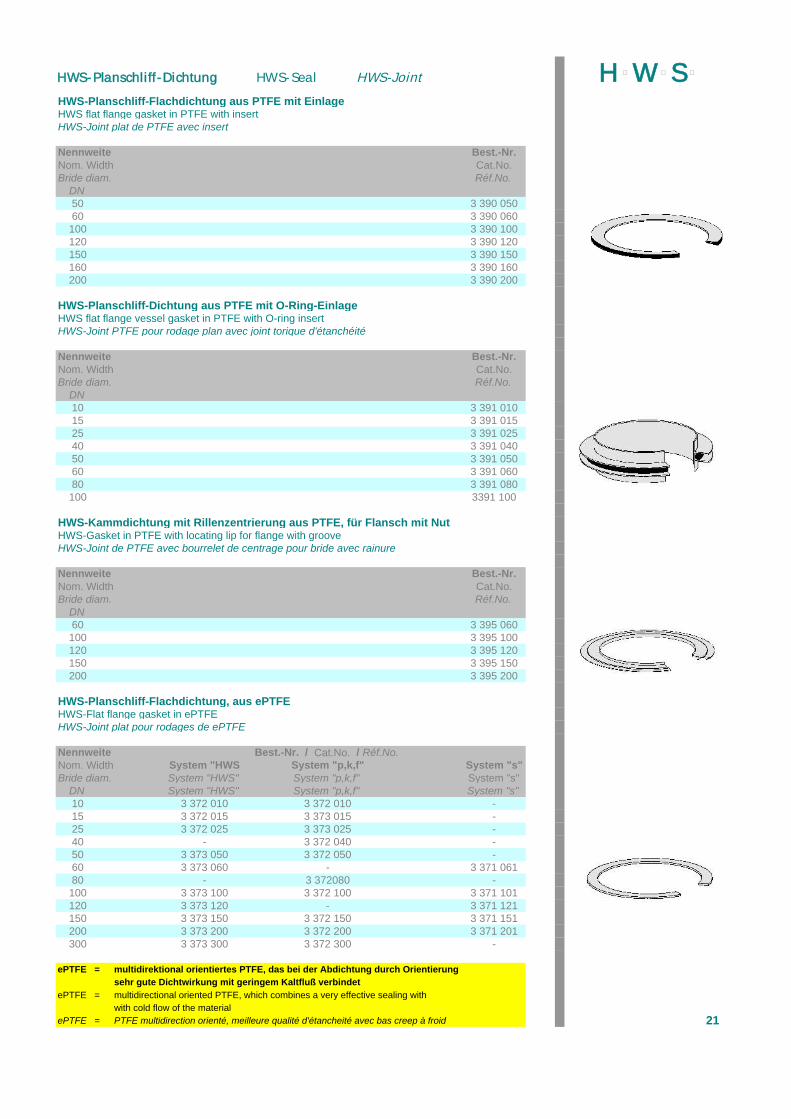
HWS-Planschliff-Flachdichtung aus PTFE mit EinlageHWS flat flange gasket in PTFE with insertHWS-Joint plat de PTFE avec insert
Nennweite Best.-Nr.Nom. Width Cat.No.Bride diam. Réf.No.
DN50 3 390 05060 3 390 060100 3 390 100120 3 390 120150 3 390 150160 3 390 160200 3 390 200
HWS-Planschliff-Dichtung aus PTFE mit O-Ring-EinlageHWS flat flange vessel gasket in PTFE with O-ring insertHWS-Joint PTFE pour rodage plan avec joint torique d'étanchéité
Nennweite Best.-Nr.Nom. Width Cat.No.Bride diam. Réf.No.
DN10 3 391 01015 3 391 01525 3 391 02540 3 391 04050 3 391 05060 3 391 06080 3 391 080100 3391 100
HWS-Kammdichtung mit Rillenzentrierung aus PTFE, für Flansch mit NutHWS-Gasket in PTFE with locating lip for flange with grooveHWS-Joint de PTFE avec bourrelet de centrage pour bride avec rainure
Nennweite Best.-Nr.Nom. Width Cat.No.Bride diam. Réf.No.
DN60 3 395 060100 3 395 100120 3 395 120150 3 395 150200 3 395 200
HWS-Planschliff-Flachdichtung, aus ePTFEHWS-Flat flange gasket in ePTFEHWS-Joint plat pour rodages de ePTFE
Nennweite Best.-Nr. / Cat.No. / Réf.No.Nom. Width System "HWS System "p,k,f" System "s"Bride diam. System "HWS" System "p,k,f" System "s"
DN System "HWS" System "p,k,f" System "s"10 3 372 010 3 372 010 -15 3 372 015 3 373 015 -25 3 372 025 3 373 025 -40 - 3 372 040 -50 3 373 050 3 372 050 -60 3 373 060 - 3 371 06180 - 3 372080 -100 3 373 100 3 372 100 3 371 101120 3 373 120 - 3 371 121150 3 373 150 3 372 150 3 371 151200 3 373 200 3 372 200 3 371 201300 3 373 300 3 372 300 -
ePTFE = multidirektional orientiertes PTFE, das bei der Abdichtung durch Orientierungsehr gute Dichtwirkung mit geringem Kaltfluß verbindet
ePTFE = multidirectional oriented PTFE, which combines a very effective sealing withwith cold flow of the material
ePTFE = PTFE multidirection orienté, meilleure qualité d'étancheité avec bas creep à froid 21
H þW þS þHWS-Planschliff-Dichtung HWS-Seal HWS-Joint
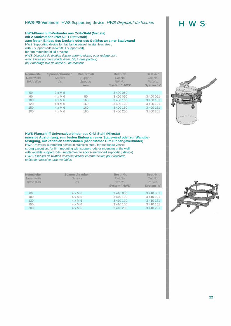
HWS-Planschliff-Verbinder aus CrNi-Stahl (Nirosta)mit 2 Stativstäben (NW 50: 1 Stativstab)zum festen Einbau des Deckels oder des Gefäßes an einer StativwandHWS Supporting device for flat flange vessel, in stainless steel,with 2 support rods (NW 50; 1 support rod),for firm mounting of lid or vesselHWS-Dispositif de fixation d'acier chrome-nickel, pour rodage plan,avec 2 bras porteurs (bride diam. 50; 1 bras porteur)pour montage fixe de dôme ou de réacteur
Nennweite Spannschrauben Rastermaß Best.-Nr. Best.-Nr. Nom.width Screws Support Cat.No. Cat.No. Bride diam. Vis Support Réf.No. Réf.No.
mm System "HWS" System "s"
50 3 x M 5 - 3 400 050 -60 4 x M 6 80 3 400 060 3 400 061100 4 x M 6 160 3 400 100 3 400 101120 4 x M 6 160 3 400 120 3 400 121150 4 x M 6 160 3 400 150 3 400 151200 4 x M 6 160 3 400 200 3 400 201
HWS-Planschliff-Universalverbinder aus CrNi-Stahl (Nirosta)massive Ausführung, zum festen Einbau an einer Stativwand oder zur Wandbe-festigung, mit variablen Stativstäben (nachrüstbar zum Einhängeverbinder)HWS-Universal supporting device in stainless steel, for flat flange vessel,strong execution, for firm mounting with support rods or mounting at the wall,with variable support rods (supplement to above-mentioned supporting device)HWS-Dispositif de fixation universel d'acier chrome-nickel, pour réacteur,,exécution massive, bras variables
Nennweite Spannschrauben Best.-Nr. Best.-Nr. Nom.width Screws Cat.No. Cat.No. Bride diam. Vis Réf.No. Réf.No.
System "HWS" System "s"
60 4 x M 6 3 410 060 3 410 061100 4 x M 6 3 410 100 3 410 101120 4 x M 6 3 410 120 3 410 121150 4 x M 6 3 410 150 3 410 151200 4 x M 6 3 410 200 3 410 201
22
H þW þS þHWS-PS-Verbinder HWS-Supporting device HWS-Dispositif de fixation
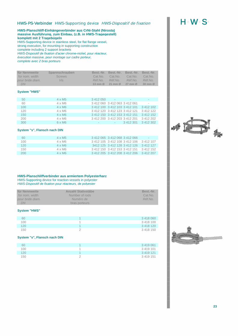
HWS-Planschliff-Einhängeverbinder aus CrNi-Stahl (Nirosta)massive Ausführung, zum Einbau, (z.B. in HWS-Tragegestell)komplett mit 2 TragebügelnHWS-Supporting device in stainless steel, for flat flange vessel,strong execution, for mounting in supporting constructioncomplete including 2 support bracketsHWS-Dispositif de fixation d'acier chrome-nickel, pour réacteur,éxecution massive, pour montage sur cadre porteur,complete avec 2 bras porteurs
für Nennweite Spannschrauben Best.-Nr. Best.-Nr. Best.-Nr. Best.-Nr. for nom. width Screws Cat.No. Cat.No. Cat.No. Cat.No.pour bride.diam. Vis Réf.No. Réf.No. Réf.No. Réf.No.
DN 13 mm Ø 21 mm Ø 27 mm Ø 30 mm Ø
System "HWS"
50 4 x M5 3 412 050 - - -60 4 x M6 3 412 060 3 412 063 3 412 061 -100 4 x M6 3 412 100 3 412 103 3 412 101 3 412 102120 4 x M6 3 412 120 3 412 123 3 412 121 3 412 122150 4 x M6 3 412 150 3 412 153 3 412 151 3 412 152200 4 x M6 3 412 200 3 412 203 3 412 201 3 412 202300 6 x M6 - - 3 412 301 3 412 302
System "s", Flansch nach DIN
60 4 x M5 3 412 065 3 412 068 3 412 066 -100 4 x M6 3 412 105 3 412 108 3 412 106 3 412 107120 4 x M6 3412 125 3 412 128 3 412 126 3 412 127150 4 x M6 3 412 150 3 412 153 3 412 151 3 412 152200 4 x M6 3 412 205 3 412 208 3 412 206 3 412 207
HWS-Planschliffverbinder aus armiertem PolyesterharzHWS-Supporting device for reaction vessels in polyesterHWS-Dispositif de fixation pour réacteurs, de polyester
für Nennweite Anzahl Stativstäbe Best.-Nr. for nom. width Number of rods Cat.No.pour bride.diam. Numéro de Réf.No.
DN bras porteurs
System "HWS"
60 1 3 418 060100 1 3 418 100120 1 3 418 120150 2 3 418 150
System "s", Flansch nach DIN
60 1 3 419 061100 1 3 419 101120 1 3 419 121150 2 3 419 151
23
H þW þS þHWS-PS-Verbinder HWS-Supporting device HWS-Dispositif de fixation

HWS-Schnellverschluss aus CrNi-Stahl, HWS-Quick release clamp in stainless steelHWS-Fermeture rapide en acier-chrome-nickel
Nennweite Best.-Nr. Best.-Nr. Nom.width Cat.No. Cat.No. Bride diam. Réf.No. Réf.No.
DN System "HWS" System "s" *
35 - 3 421 03560 3 420 060 3 421 061100 3 420 100 3 421 101120 3 420 120 3 421 121150 3 420 150 3 421 151200 3 420 200 3 421 201
HWS-Schnellverschluss aus CrNi-Stahl, mit 2 StativstangenHWS-Quick release clamp in stainless steel, with 2 support rodsHWS-Fermeture rapide en acier-chrome-nickel, avec bras porteur
Nennweite Best.-Nr. Best.-Nr. Nom.width Cat.No. Cat.No. Bride diam. Réf.No. Réf.No.
DN System "HWS" System "s" *
35 - 3 431 03560 3 430 060 3 431 061100 3 430 100 3 431 101120 3 430 120 3 431 121150 3 430 150 3 431 151200 3 430 200 3 431 201
* Diese Schnellverschlüsse können nur mit folgenden Dichtungenverwendet werden:
FlachdichtungKammdichtungO-Ring-DichtungFlachdichtung mit Rillenzentrierung
* These release clamps can be used with following sealsflat flange gasketseals with grooveO-ring-sealsgasket with locating lip
* Les fermetures sont prévues pour le bridesJoint plat de PTFERondelle d'étanchéite avec rainureJoint-O avec rainureJoint avec bourrelet de centrage
24
H þW þS þHWS-Schnellverschluss HWS-Quick release clamp HWS-Fermeture rapide
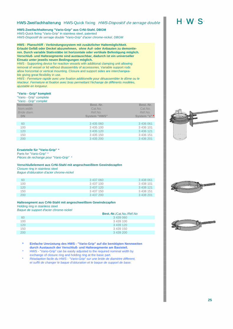
HWS-Zweifachhalterung "Vario-Grip" aus CrNi-Stahl. DBGMHWS-Quick fixing "Vario-Grip" in stainless steel, patentedHWS-Dispositif de serrage double "Vario-Grip" d'acier chrome-nickel, DBGM
HWS - Planschliff - Verbindungssystem mit zusätzlicher Haltemöglichkeit.Erlaubt Gefäß oder Deckel abzunehmen, ohne Auf- oder Anbauten zu demontie-ren. Durch variable Stativstäbe ist horizontale oder vertikale Befestigung möglich.Verschluß- und Haltesegmente sind austauschbar, dadurch ist ein universellerEinsatz unter jeweils neuen Bedingungen möglich.HWS - Supporting device for reaction vessels with additional clamping unit allowingremoval of vessel or lid without disassembly of accessories. Variable support rodsallow horizontal or vertical mounting. Closure and support sides are interchangea-ble giving great flexibility in use.HWS - Fermeture rapide avec une fixation additionelle pour désassembler le dôme ou leréacteur. Fermeture et fixation avec bras permettant l'échange de différents modèles,ajustable en longueur.
"Vario - Grip" komplett"Vario - Grip" complete"Vario - Grip" completNennweite Best.-Nr. Best.-Nr. Nom.width Cat.No. Cat.No. Bride diam. Réf.No. Réf.No.
DN System "HWS" System "s" *
60 3 435 060 3 436 061100 3 435 100 3 436 101120 3 435 120 3 436 121150 3 435 150 3 436 151200 3 435 200 3 436 201
Ersatzteile für "Vario-Grip" *Parts for "Vario-Grip" *Pièces de rechange pour "Vario-Grip" *
Verschlußelement aus CrNi-Stahl mit angeschweißtem GewindezapfenClosure ring in stainless steelBague d'obturation d'acier chrome-nickel
60 3 437 060 3 438 061100 3 437 100 3 438 101120 3 437 120 3 438 121150 3 437 150 3 438 151200 3 437 200 3 438 201
Haltesegment aus CrNi-Stahl mit angeschweißtem GewindezapfenHolding ring in stainless steelBague de support d'acier chrome-nickel
Best.-Nr./Cat.No./Réf.No60 3 439 060100 3 439 100120 3 439 120150 3 439 150200 3 439 200
* Einfache Umrüstung des HWS - "Vario-Grip" auf die benötigten Nennweitendurch Austausch der Verschluß- und Haltesegmente am Basisteil.
* HWS - "Vario-Grip" can be easily adjusted to the required nominal width byexchange of closure ring and holding ring at the basic part.
* Réadaption facile du HWS - "Vario-Grip" sur une bride de diamètre different,et suffit de changer le baque d'obturation et le baque de support de base.
25
H þW þS þHWS-Zweifachhalterung HWS-Quick fixing HWS-Dispositif de serrage double

bestehend aus zwei ungeteilten Schellenringen, zwei Beilagen * Ausführung A: Endlosfeder aus Edelstahl* Ausführung B: DuroplastZulässige produktseitige Betriebstemperatur 200 °C
consisting of 2 rings and 2 additions in 2 executions* execution A: coil in s/s* execution B: in plastic (Duroplast)Temp. Max.: 200 °C
avec 2 bagues et 2 addtitives en 2 éxécutions* Exécution A: resort en inox* Ausführung B: en matière plastique (Duroplast)Temp. Max.: 200 °C
HWS-Schellenringverbinder, KunststoffausführungHWS-Clamp connection in resistant phenolic resinHWS-Collier de fixation en plastique
Nennweite äußerer Ø Best.-Nr. Best.-Nr. Nom.width outer diam. Cat.No. Cat.No. Bride diam. Diam. Ext. Réf.No. Réf.No.
DN mm A * B *
10 - - 3 440 01015 64 - 3 440 01525 92 - 3 440 02540 - 3 440 04050 131 3 442 050 3 440 05080 3 442 080 3 440 080100 192 3 442 100 3 440 100150 247 3 442 150 3 440 150200 307 3 442 200 3 440 200300 425 3 442 300 3 440 300
HWS-Schellenringverbinder, SiluminausführungHWS-Clamp connection in Silumin for use up to 200 °CHWS-Collier de fixation en Alpax pour réaction sous 200 °C
Nennweite äußerer Ø Best.-Nr. Best.-Nr. Nom.width outer diam. Cat.No. Cat.No. Bride diam. Diam. Ext. Réf.No. Réf.No.
DN mm A * B *
15 64 - 3 441 01525 92 - 3 441 02540 - 3 441 04050 131 3 443 050 3 441 05080 3 443 080 3 441 080100 192 3 443 100 3 441 100150 247 3 443 150 3 441 150200 307 3 443 200 3 441 200300 425 3 443 300 3 441 300
V2A-Endlos-Schraubenfeder, zum Austausch der Standardbeilage(erlaubt einfache Montage, verhindert ungewolltes Abrutschen des Schellenringes)Torsion coil, stainless steel, for easy mountingRessort de torsion, d'acier, pour l'assemblage facile
Nennweite Best.-Nr. Nom.width Cat.No. Bride diam. Réf.No.
50 3 441 90580 3 441 908100 3 441 910150 3 441 915200 3 441 920300 3 441 930 26
H þW þS þHWS-Schellenring-Verbinder HWS-Clamp connection HWS-Collier de fixation
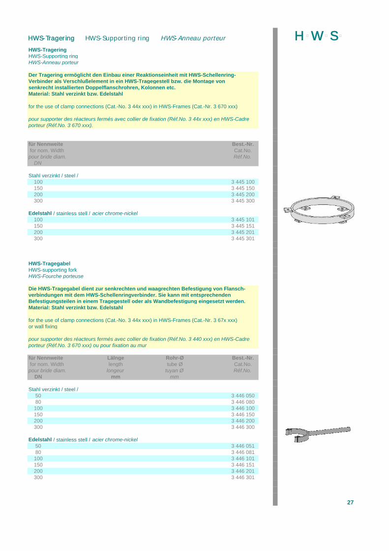
HWS-TrageringHWS-Supporting ringHWS-Anneau porteur
Der Tragering ermöglicht den Einbau einer Reaktionseinheit mit HWS-Schellenring-Verbinder als Verschlußelement in ein HWS-Tragegestell bzw. die Montage von senkrecht installierten Doppelflanschrohren, Kolonnen etc.Material: Stahl verzinkt bzw. Edelstahl
for the use of clamp connections (Cat.-No. 3 44x xxx) in HWS-Frames (Cat.-Nr. 3 670 xxx)
pour supporter des réacteurs fermés avec collier de fixation (Réf.No. 3 44x xxx) en HWS-Cadreporteur (Réf.No. 3 670 xxx).
für Nennweite Best.-Nr. for nom. Width Cat.No.pour bride diam. Réf.No.
DN
Stahl verzinkt / steel /100 3 445 100150 3 445 150200 3 445 200300 3 445 300
Edelstahl / stainless stell / acier chrome-nickel100 3 445 101150 3 445 151200 3 445 201300 3 445 301
HWS-TragegabelHWS-supporting forkHWS-Fourche porteuse
Die HWS-Tragegabel dient zur senkrechten und waagrechten Befestigung von Flansch-verbindungen mit dem HWS-Schellenringverbinder. Sie kann mit entsprechenden Befestigungsteilen in einem Tragegestell oder als Wandbefestigung eingesetzt werden.Material: Stahl verzinkt bzw. Edelstahl
for the use of clamp connections (Cat.-No. 3 44x xxx) in HWS-Frames (Cat.-Nr. 3 67x xxx)or wall fixing
pour supporter des réacteurs fermés avec collier de fixation (Réf.No. 3 440 xxx) en HWS-Cadreporteur (Réf.No. 3 670 xxx) ou pour fixation au mur
für Nennweite Lälnge Rohr-Ø Best.-Nr. for nom. Width length tube Ø Cat.No.pour bride diam. longeur tuyan Ø Réf.No.
DN mm mm
Stahl verzinkt / steel /50 3 446 05080 3 446 080100 3 446 100150 3 446 150200 3 446 200300 3 446 300
Edelstahl / stainless stell / acier chrome-nickel50 3 446 05180 3 446 081100 3 446 101150 3 446 151200 3 446 201300 3 446 301
27
H þW þS þHWS-Tragering HWS-Supporting ring HWS-Anneau porteur
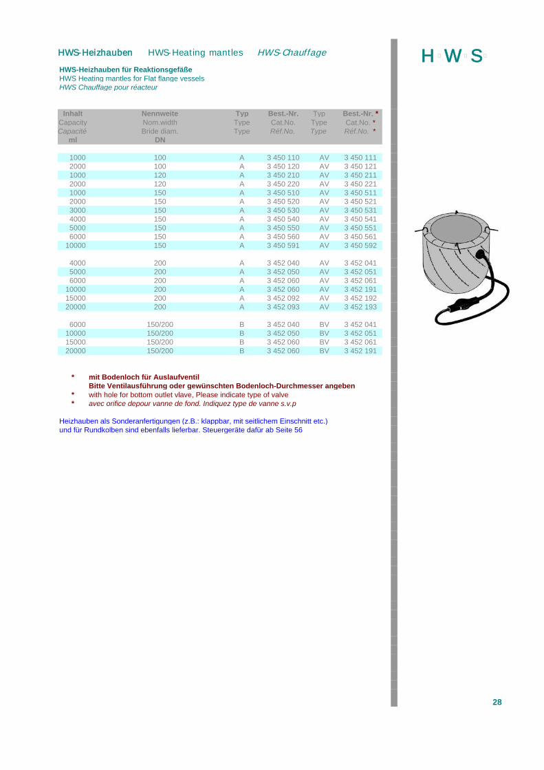
HWS-Heizhauben für ReaktionsgefäßeHWS Heating mantles for Flat flange vesselsHWS Chauffage pour réacteur
Inhalt Nennweite Typ Best.-Nr. Typ Best.-Nr. *Capacity Nom.width Type Cat.No. Type Cat.No. *Capacité Bride diam. Type Réf.No. Type Réf.No. *
ml DN
1000 100 A 3 450 110 AV 3 450 1112000 100 A 3 450 120 AV 3 450 1211000 120 A 3 450 210 AV 3 450 2112000 120 A 3 450 220 AV 3 450 2211000 150 A 3 450 510 AV 3 450 5112000 150 A 3 450 520 AV 3 450 5213000 150 A 3 450 530 AV 3 450 5314000 150 A 3 450 540 AV 3 450 5415000 150 A 3 450 550 AV 3 450 5516000 150 A 3 450 560 AV 3 450 561
10000 150 A 3 450 591 AV 3 450 592
4000 200 A 3 452 040 AV 3 452 0415000 200 A 3 452 050 AV 3 452 0516000 200 A 3 452 060 AV 3 452 061
10000 200 A 3 452 060 AV 3 452 19115000 200 A 3 452 092 AV 3 452 19220000 200 A 3 452 093 AV 3 452 193
6000 150/200 B 3 452 040 BV 3 452 04110000 150/200 B 3 452 050 BV 3 452 05115000 150/200 B 3 452 060 BV 3 452 06120000 150/200 B 3 452 060 BV 3 452 191
* mit Bodenloch für AuslaufventilBitte Ventilausführung oder gewünschten Bodenloch-Durchmesser angeben
* with hole for bottom outlet vlave, Please indicate type of valve* avec orifice depour vanne de fond. Indiquez type de vanne s.v.p
Heizhauben als Sonderanfertigungen (z.B.: klappbar, mit seitlichem Einschnitt etc.)und für Rundkolben sind ebenfalls lieferbar. Steuergeräte dafür ab Seite 56
28
H þW þS þHWS-Heizhauben HWS-Heating mantles HWS-Chauffage
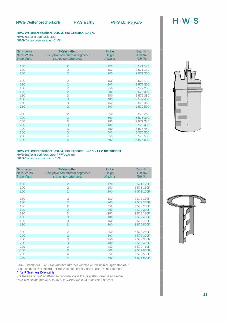
HWS-Wellenbrecherkorb DBGM, aus Edelstahl 1.4571HWS-Baffle in stainless steelHWS-Contre pale en acier Cr-Ni
Nennweite Störlamellen Höhe Best.-Nr.Nom. Width Disruptive commutator segments Height Cat.No.Bride diam. Lames perturbatrices Hauteur Réf.No.
100 2 120 3 571 120100 2 150 3 571 150100 2 200 3 571 200
150 2 150 3 572 150150 2 200 3 572 200150 2 250 3 572 250150 2 300 3 572 300150 3 350 3 572 350150 3 400 3 572 400150 3 450 3 572 450150 3 500 3 572 500
200 2 250 3 573 250200 2 300 3 573 300200 3 350 3 573 350200 3 400 3 573 400200 3 450 3 573 450200 3 500 3 573 500200 4 550 3 573 550200 4 600 3 573 600
HWS-Wellenbrecherkorb DBGM, aus Edelstahl 1.4571 / PFA beschichtetHWS-Baffle in stainless steel / PFA coatedHWS-Contre pale en acier Cr-Ni
Nennweite Störlamellen Höhe Best.-Nr.Nom. Width Disruptive commutator segments Height Cat.No.Bride diam. Lames perturbatrices Hauteur Réf.No.
100 2 120 3 571 120P100 2 150 3 571 150P100 2 200 3 571 200P
150 2 150 3 572 150P150 2 200 3 572 200P150 2 250 3 572 250P150 2 300 3 572 300P150 3 350 3 572 350P150 3 400 3 572 400P150 3 450 3 572 450P150 3 500 3 572 500P
200 2 250 3 573 250P200 2 300 3 573 300P200 3 350 3 573 350P200 3 400 3 573 400P200 3 450 3 573 450P200 3 500 3 573 500P200 4 550 3 573 550P200 4 600 3 573 600P
Beim Einsatz des HWS-Wellenbrecherkorbes empfehlen wir unsere speziell daraufabgestimmten Propellerrührer mit verschiedenen verstellbaren * Rührebenen(* für Rührer aus Edelstahl)For the use of HWS-baffles the cooperation with a propeller stirrer is advisable.Pour l'emploide condre pale ou doit traviller avec un agitateur à hélices.
29
H þW þS þHWS-Wellenbrecherkorb HWS-Baffle HWS-Contre pale
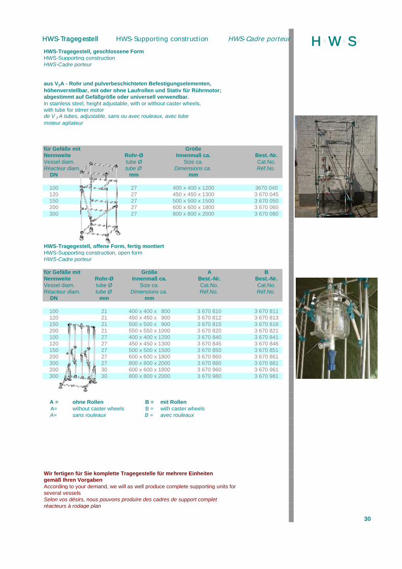
HWS-Tragegestell, geschlossene FormHWS-Supporting constructionHWS-Cadre porteur
aus V2A - Rohr und pulverbeschichteten Befestigungselementen,höhenverstellbar, mit oder ohne Laufrollen und Stativ für Rührmotor;abgestimmt auf Gefäßgröße oder universell verwendbar.in stainless steel, height adjustable, with or without caster wheels,with tube for stirrer motorde V 2 A tubes, adjustable, sans ou avec rouleaux, avec tubemoteur agitateur
für Gefäße mit GrößeNennweite Rohr-Ø Innenmaß ca. Best.-Nr.Vessel diam. tube Ø Size ca. Cat.No.Réacteur diam. tube Ø Dimensions ca. Réf.No.
DN mm mm
100 27 400 x 400 x 1200 3670 040120 27 450 x 450 x 1300 3 670 045150 27 500 x 500 x 1500 3 670 050200 27 600 x 600 x 1800 3 670 060300 27 800 x 800 x 2000 3 670 080
HWS-Tragegestell, offene Form, fertig montiertHWS-Supporting construction, open formHWS-Cadre porteur
für Gefäße mit Größe A BNennweite Rohr-Ø Innenmaß ca. Best.-Nr. Best.-Nr.Vessel diam. tube Ø Size ca. Cat.No. Cat.No.Réacteur diam. tube Ø Dimensions ca. Réf.No. Réf.No.
DN mm mm
100 21 400 x 400 x 800 3 670 810 3 670 811120 21 450 x 450 x 900 3 670 812 3 670 813150 21 500 x 500 x 900 3 670 815 3 670 816200 21 550 x 550 x 1000 3 670 820 3 670 821100 27 400 x 400 x 1200 3 670 840 3 670 841120 27 450 x 450 x 1300 3 670 845 3 670 846150 27 500 x 500 x 1500 3 670 850 3 670 851200 27 600 x 600 x 1800 3 670 860 3 670 861300 27 800 x 800 x 2000 3 670 880 3 670 881200 30 600 x 600 x 1800 3 670 960 3 670 961300 30 800 x 800 x 2000 3 670 980 3 670 981
A = ohne Rollen B = mit RollenA= without caster wheels B = with caster wheelsA= sans rouleaux B = avec rouleaux
Wir fertigen für Sie komplette Tragegestelle für mehrere Einheitengemäß Ihren VorgabenAccording to your demand, we will as well produce complete supporting units forseveral vesselsSelon vos désirs, nous pouvons produire des cadres de support completréacteurs à rodage plan
30
H þW þS þHWS-Tragegestell HWS-Supporting construction HWS-Cadre porteur
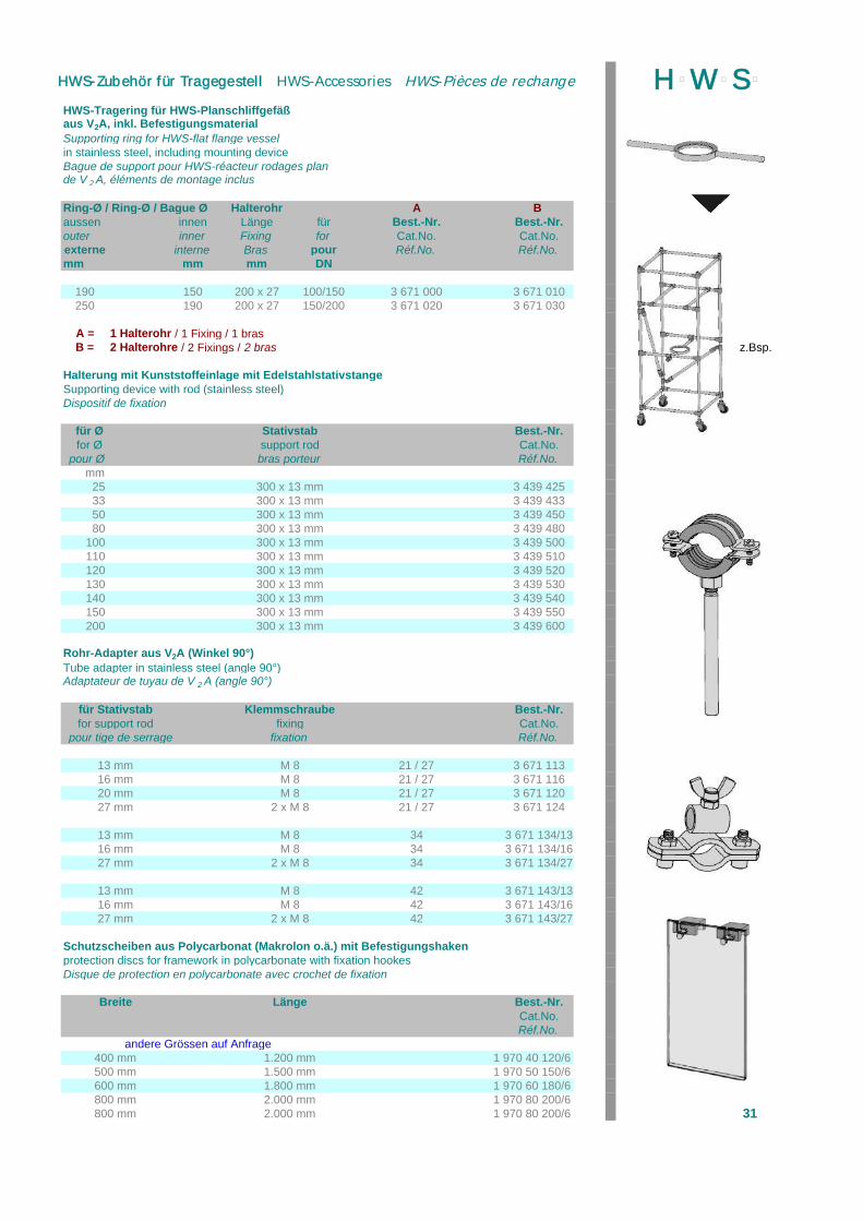
HWS-Tragering für HWS-Planschliffgefäßaus V2A, inkl. BefestigungsmaterialSupporting ring for HWS-flat flange vesselin stainless steel, including mounting deviceBague de support pour HWS-réacteur rodages plande V 2 A, éléments de montage inclus
Ring-Ø / Ring-Ø / Bague Ø Halterohr A B aussen innen Länge für Best.-Nr. Best.-Nr.outer inner Fixing for Cat.No. Cat.No.externe interne Bras pour Réf.No. Réf.No.mm mm mm DN
190 150 200 x 27 100/150 3 671 000 3 671 010250 190 200 x 27 150/200 3 671 020 3 671 030
A = 1 Halterohr / 1 Fixing / 1 brasB = 2 Halterohre / 2 Fixings / 2 bras z.Bsp.
Halterung mit Kunststoffeinlage mit EdelstahlstativstangeSupporting device with rod (stainless steel)Dispositif de fixation
für Ø Stativstab Best.-Nr. for Ø support rod Cat.No.
pour Ø bras porteur Réf.No.mm
25 300 x 13 mm 3 439 42533 300 x 13 mm 3 439 43350 300 x 13 mm 3 439 45080 300 x 13 mm 3 439 480
100 300 x 13 mm 3 439 500110 300 x 13 mm 3 439 510120 300 x 13 mm 3 439 520130 300 x 13 mm 3 439 530140 300 x 13 mm 3 439 540150 300 x 13 mm 3 439 550200 300 x 13 mm 3 439 600
Rohr-Adapter aus V2A (Winkel 90°)Tube adapter in stainless steel (angle 90°)Adaptateur de tuyau de V 2 A (angle 90°)
für Stativstab Klemmschraube Best.-Nr.for support rod fixing Cat.No.
pour tige de serrage fixation Réf.No.
13 mm M 8 21 / 27 3 671 11316 mm M 8 21 / 27 3 671 11620 mm M 8 21 / 27 3 671 12027 mm 2 x M 8 21 / 27 3 671 124
13 mm M 8 34 3 671 134/1316 mm M 8 34 3 671 134/1627 mm 2 x M 8 34 3 671 134/27
13 mm M 8 42 3 671 143/1316 mm M 8 42 3 671 143/1627 mm 2 x M 8 42 3 671 143/27
Schutzscheiben aus Polycarbonat (Makrolon o.ä.) mit Befestigungshakenprotection discs for framework in polycarbonate with fixation hookesDisque de protection en polycarbonate avec crochet de fixation
Breite Länge Best.-Nr.Cat.No.Réf.No.
andere Grössen auf Anfrage400 mm 1.200 mm 1 970 40 120/6500 mm 1.500 mm 1 970 50 150/6600 mm 1.800 mm 1 970 60 180/6800 mm 2.000 mm 1 970 80 200/6800 mm 2.000 mm 1 970 80 200/6 31
H þW þS þHWS-Zubehör für Tragegestell HWS-Accessories HWS-Pièces de rechange

HWS-Ablagetablett aus V2A, inkl. BefestigungselementHWS-Shelf in stainless steel, incl. mounting deviceHWS-plateau, en V 2 A, éléments de montage inclus
Tablettgröße * Halterohr, V2A Best.-Nr.Size of shelf * Fixing, stainless steel Cat.No.
dimensions de plateau * Bras, V 2 A Réf.No.mm mm
150 x 100 Ø 27 x 500 mm 3 671 200200 x 150 Ø 27 x 500 mm 3 671 250
HWS-Einlegewanne, aus EdelstahlHWS-Shelf with walls, in stainless steelHWS-Plateau en V 2 A
Abmessungen * Best.-Nr.Size * Cat.No.
Dimensions * Réf.No.mm
380 x 380 x 50 x 1,5 3 671 300480 x 480 x 50 x 1,5 3 671 305580 x 580 x 50 x 1,5 3 671 310780 x 780 x 50 x 1,5 3 671 320
HWS-TischtragegestellHWS-supporting construction for table versionHWS-Cadre porteur modèle de table
aus V2A-Rohr (21mm) und pulverbeschichteten Befestigungselementen, höhenverstellbar, mit Stativ für Rührmotorin stainless steel (21mm), height adjustable, with tube for stirrer motorde V 2 A tubes (21mm), ajustable, mobile, avec moteur agitateur
für Nennweite Abmessungen * Höhe Best.-Nr.for nominal width Size * Height Cat.No.
Bride diam. Dimensions * Hauteur Réf.No.DN mm mm
60 300 x 300 600 3 675 065100 400 x 400 750 3 675 105120 400 x 400 750 3 675 125150 450 x 450 750 3 675 155200 500 x 500 820 3 675 205300 500 x 500 900 3 675 305
Die passenden HWS-Planschliff-Einhängeverbinder finden Sie auf Seite 23You can find suitable fixations of vessels on page 23Vous trouvez les fixations pour réacteurs à la page 23
* Sonderanfertigungen nach Ihren Angaben möglich. Wir erbitten Ihre Anfrage* Special executions according to your requirements on request* Execution speciale sur demande
32
H þW þS þHWS-Tragegestell/Zubehör HWS-Supporting construction/Accessories HWS-Cadre porteur
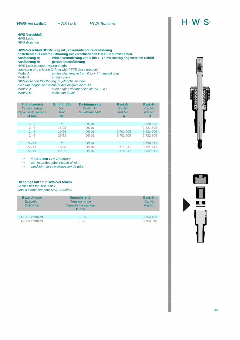
HWS-VerschlußHWS-LockHWS-Bouchon
HWS-Verschluß DBGM., reg.int., vakuumdichte Durchführungbestehend aus einem Silikonring mit verschiedenen PTFE-Schutzscheiben.Ausführung A: Winkelveränderung von 0 bis +- 4 ° mit schräg angesetztem SchliffAusführung B: gerade DurchführungHWS-Lock patented, vacuum-tightconsisting of a silicone O-Ring with PTFE-discs protectionModel A: angles changeable from 0 to +-4 °, angled jointModel B: straight passHWS-Bouchon DBGM. reg.int.,étanche en videavec une bague de silicone et des disques de PTFEModèle A: avec angles changeables de 0 à +- 4 °Modèle B: éxécution droite
Spannbereich Schliffgröße Dichtungssatz Best.-Nr. Best.-Nr.Tension range Joint Sealing kit Cat.No. Cat.No.
Capacité de serrage RIN Jeu d'étanchéité Réf.No. Réf.No.Ø mm NS A B
2 - 5 ** DS 01 - 3 720 0052 - 5 14/23 DS 01 - 3 721 4052 - 5 19/26 DS 01 3 701 905 3 721 9052 - 5 29/32 DS 01 3 702 905 3 722 905
5 - 11 ** DS 02 3 730 0115 - 11 19/26 DS 02 3 711 911 3 731 9115 - 11 29/32 DS 02 3 712 911 3 732 911
** mit Stutzen zum Ansetzen** with extended tube instead of joint** sand joint, avec prolongation de tube
Dichtungssätze für HWS-VerschlußSealing kits for HWS-LockJeux d'étanchéité pour HWS-Bouchon
Bezeichnung Spannbereich Best.-Nr.Execution Tension range Cat.No.Exécution Capacité de serrage Réf.No.
Ø mm
DS 01 komplett 2 - 5 3 754 450DS 02 komplett 5 - 11 3 754 910
33
H þW þS þHWS-Verschluß HWS-Lock HWS-Bouchon
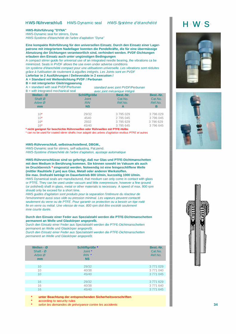
HWS-Rührführung "DYNA"HWS-Dynamic seal for stirrers, DynaHWS-Système d'étanchéité de l'arbre d'agitation "Dyna"
Eine kompakte Rührführung für den universellen Einsatz. Durch den Einsatz einer Lager-patrone mit integriertem Nadellager konnten die Pendelkräfte, die für eine übermässigeAbnutzung der Dichtungen verantwortlich sind, verhindert werden. PVDF-Dichtungenerlauben den Einsatz auch unter ungünstigen BedingungenA compact stirrer guide for universal use of an integrated needle bearing, the vibrations ca beminimized. Seals in PVDF allows the use even under adverse conditionsUn système d'étanchéité compact pour une utilisationn universelle. Les vibrations sont réduitesgrâce à l'utilisation de roulement à aiguilles intégrés. Les Joints sont en PVDFLieferbar in 2 Ausführungen / Delieverable in 2 execution / A = Standard mit Wellendichtung PVDF / PerbunanB = mit intergrierter GleitringpaarungA = standard with seal PVDF/Perbunan standard avec joint PVDF/PerbunanB = with integrated mechanical seal avec joint mécanique intégré
Wellen - Ø Schliffgröße Best.-Nr. Best.-Nr.Shaft Ø Joint Cat.No. Cat.No.Arbre Ø RIN Réf.No. Réf.No.
mm NS A B
10* 29/32 3 795 029 3 796 02910* 4540 2 795 045 3 796 04516* 2932 3 795 629 3 796 629 16* 45/40 3 795 645 3 796 645
* nicht geeignet für beschichte Rührerwellen oder Rührwellen mit PTFE-Hüllen* can no be used for coated stirrer shafts / non adapté des arbres d'agitation revêtus PTFE et autres
HWS-Rührverschluß, selbstnachstellend, DBGM., HWS-Dynamic seal for stirrers, self-adjusting, Pat.pend.HWS-Système d'étanchéité de l'arbre d'agitation, ajustage automatique
HWS-Rührverschlüsse sind so gefertigt, daß nur Glas und PTFE-Dichtmanschettenmit dem Medium in Berührung kommen. Sie können sowohl im Vakuum als auchim Druckbereich * eingesetzt werden. Notwendig ist eine feingeschliffene Welle(mittler Rauhtiefe 2 µm) aus Glas, Metall oder anderen Werkstoffen.Die max. Drehzahl beträgt im Dauerbetrieb 800 U/min, kurzzeitig 1000 U/min.HWS Dynamical seals are manufactured, that medium can only come in contact with glassor PTFE. They can be used under vacuum and little overpressure, however a fine ground(or polished) shaft in glass, metal or other materials is necessary. A speed of max. 800 rpmshould only be exceed for a short time.HWS guides d'agitation sont produits pour la separation l'intéreure du réacteur del'environment aussi sous vide ou pression minimal. Les vapeurs peuvent contactéseulement du verre ou de PTFE. Pour garantir ce protection ou a besoin un tige rodéfin en verre ou métal. Une vitesse de max. 800 rpm doit être excédé seulementinne courte durée.
Durch den Einsatz einer Feder aus Spezialstahl werden die PTFE-Dichtmanschettenpermanent an Welle und Glaskörper angepreßt.Durch den Einsatz einer Feder aus Spezialstahl werden die PTFE-Dichtmanschettenpermanent an Welle und Glaskörper angepreßt.Durch den Einsatz einer Feder aus Spezialstahl werden die PTFE-Dichtmanschettenpermanent an Welle und Glaskörper angepreßt.
Wellen - Ø Schliffgröße * Best.-Nr.Shaft - Ø Joint * Cat.No.Arbre Ø RIN * Réf.No.
mm NS
10 29/32 3 771 02910 40/38 3 771 04010 45/40 3 771 045
16 29/32 3 771 62916 40/38 3 771 64016 45/40 3 771 645
* unter Beachtung der entsprechenden Sicherheitsvorschriften* according to security rules* selon les demandes de prévoyance contre les accidents 34
H þW þS þHWS-Rührverschluß HWS-Dynamic seal HWS-Système d’étanchéité
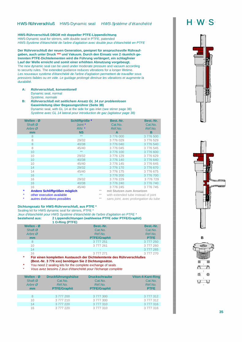
HWS-Rührverschluß DBGM mit doppelter PTFE-LippendichtungHWS-Dynamic seal for stirrers, with double seal in PTFE, patendedHWS-Système d'étanchéité de l'arbre d'agitation avec double jeux d'étanchéité en PTFE
Der Rührverschluß der neuen Generation, geeignet für anspruchsvolle Rührauf-gaben, auch unter Druck *** und Vakuum. Durch den Einsatz von 2 räumlich ge-trennten PTFE-Dichtelementen wird die Führung verlängert, ein schlagfreierLauf der Welle erreicht und somit einer erhöhten Abnutzung vorgebeugt.The new dynamic seal can be used under moderate pressure and vacuum accordingto security rules. The extended guidance reduces vibrations for a longer lifetime.Les nouveaux système d'étanchéité de l'arbre d'agitation permettent de travailler souspressions faibles ou en vide. Le guidage prolongé diminue les vibrations et augmente ladurabilité.
A: Rührverschluß, konventionellDynamic seal, normalSystème, normale
B: Rührverschluß mit seitlichem Ansatz GL 14 zur problemlosenGaseinleitung über Begasungsrührer (Seite 38)Dynamic seal, with GL 14 at the side for gas inlet (see stirrer page 38)Système avec GL 14 lateral pour introduction de gaz (agitateur page 38)
Wellen - Ø Schliffgröße * Best.-Nr. Best.-Nr.Shaft Ø Joint * Cat.No. Cat.No.Arbre Ø RIN * Réf.No. Réf.No.
mm NS A B8 ** 3 776 000 3 776 5008 29/32 3 776 029 3 776 5298 40/38 3 776 040 3 776 5408 45/40 3 776 045 3 776 545
10 ** 3 776 100 3 776 60010 29/32 3 776 129 3 776 62910 40/38 3 776 140 3 776 64010 45/40 3 776 145 3 776 645 A14 29/32 3 776 170 3 776 67014 45/40 3 776 175 3 776 67516 ** 3 776 200 3 776 70016 29/32 3 776 229 3 776 72916 40/38 3 776 240 3 776 74016 45/40 3 776 245 3 776 745
* Andere Schliffgrößen möglich ** mit Stutzen zum Ansetzen* other execution available ** with extended tube instead of joint* autres éxécutions possibles ** sans joint, avec prolongation du tube
Dichtungssatz für HWS-Rührverschluß, aus PTFE *Sealing kit for HWS dynamic seal for stirrers, PTFE *Jeux d'étanchéité pour HWS Système d'étanchéité de l'arbre d'agitation en PTFE *bestehend aus: 2 Lippendichtungen (wahlweise PTFE oder PTFE/Graphit)
1 O-Ring (PTFE)Wellen - Ø Best.-Nr. Best.-Nr.
Shaft Ø Cat.No. Cat.No.Arbre Ø Réf.No. Réf.No.
mm PTFE/Graphit PTFE B8 3 777 251 3 777 250
10 3 777 261 3 777 26014 - 3 777 26516 3 777 271 3 777 270
* Für einen kompletten Austausch der Dichtelemtente des Rührverschlußes(Best.-Nr. 3 776 xxx) benötigen Sie 2 Dichtungssätze.
* You need 2 sealing kits for the complete exchange of seals* Vous avez besoins 2 jeux d'étanchéité pour l'échange complète
Wellen - Ø Druckführungshülse Druckschraube Viton-4-Kant-RingShaft Ø Cat.No. Cat.No. Cat.No.Arbre Ø Réf.No. Réf.No. Réf.No.
mm PTFE/Graphit PTFE/Graphit PTFE
8 3 777 200 3 777 300 3 777 31210 3 777 210 3 777 300 3 777 31214 3 777 220 3 777 310 3 777 31616 3 777 220 3 777 310 3 777 316
35
H þW þS þHWS-Rührverschluß HWS-Dynamic seal HWS-Système d’étanchéité
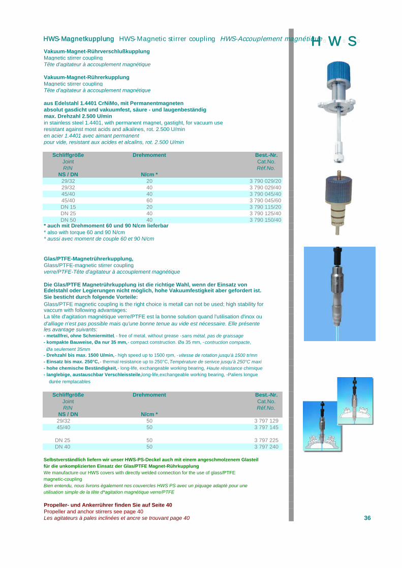
Vakuum-Magnet-RührverschlußkupplungMagnetic stirrer couplingTête d'agitateur à accouplement magnétique
Vakuum-Magnet-RührerkupplungMagnetic stirrer couplingTête d'agitateur à accouplement magnétique
aus Edelstahl 1.4401 CrNiMo, mit Permanentmagnetenabsolut gasdicht und vakuumfest, säure - und laugenbeständigmax. Drehzahl 2.500 U/minin stainless steel 1.4401, with permanent magnet, gastight, for vacuum useresistant against most acids and alkalines, rot. 2.500 U/minen acier 1.4401 avec aimant permanentpour vide, resistant aux acides et alcalins, rot. 2.500 U/min
Schliffgröße Drehmoment Best.-Nr.Joint Cat.No.RIN Réf.No.
NS / DN N/cm *29/32 20 3 790 029/2029/32 40 3 790 029/4045/40 40 3 790 045/4045/40 60 3 790 045/60DN 15 20 3 790 115/20DN 25 40 3 790 125/40DN 50 40 3 790 150/40
* auch mit Drehmoment 60 und 90 N/cm lieferbar* also with torque 60 and 90 N/cm* aussi avec moment de couple 60 et 90 N/cm
Glas/PTFE-Magnetrührerkupplung, Glass/PTFE-magnetic stirrer couplingverre/PTFE-Tête d'agitateur à accouplement magnétique
Die Glas/PTFE Magnetrührkupplung ist die richtige Wahl, wenn der Einsatz vonEdelstahl oder Legierungen nicht möglich, hohe Vakuumfestigkeit aber gefordert ist.Sie besticht durch folgende Vorteile:Glass/PTFE magnetic coupling is the right choice is metall can not be used; high stability forvaccum with following advantages:La tête d'agitation magnétique verre/PTFE est la bonne solution quand l'utilisation d'inox ou d'alliage n'est pas possible mais qu'une bonne tenue au vide est nécessaire. Elle présenteles avantage suivants:- metallfrei, ohne Schmiermittel, - free of metal, without grease - sans métal, pas de graissage- kompakte Bauweise, Øa nur 35 mm, - compact construction. Øa 35 mm, - contruction compacte,
Øa seulement 35mm- Drehzahl bis max. 1500 U/min, - high speed up to 1500 rpm, - vitesse de rotation jusqu'à 1500 tr/mn- Einsatz bis max. 250°C, - thermal resistance up to 250°C, Température de serivce jusqu'à 250°C maxi- hohe chemische Beständigkeit, - long-life, exchangeable working bearing, -Haute résistance chimique- langlebige, austauschbar Verschleissteile, long-life,exchangeable working bearing, -Paliers longue
durée remplacables
Schliffgröße Drehmoment Best.-Nr.Joint Cat.No.RIN Réf.No.
NS / DN N/cm *29/32 50 3 797 12945/40 50 3 797 145
DN 25 50 3 797 225DN 40 50 3 797 240
Selbstverständlich liefern wir unser HWS-PS-Deckel auch mit einem angeschmolzenem Glasteilfür die unkomplizierten Einsatz der Glas/PTFE Magnet-RührkupplungWe manufacture our HWS covers with directly welded connection for the use of glass/PTFEmagnetic-couplingBien entendu, nous livrons ègalement nos couvercles HWS PS avec un piquage adaptè pour uneutilisation simple de la tête d*agitation magnétique verre/PTFE
Propeller- und Ankerrührer finden Sie auf Seite 40Propeller and anchor stirrers see page 40Les agitateurs à pales inclinées et ancre se trouvant page 40 36
H þW þS þHWS-Magnetkupplung HWS-Magnetic stirrer coupling HWS-Accouplement magnétique
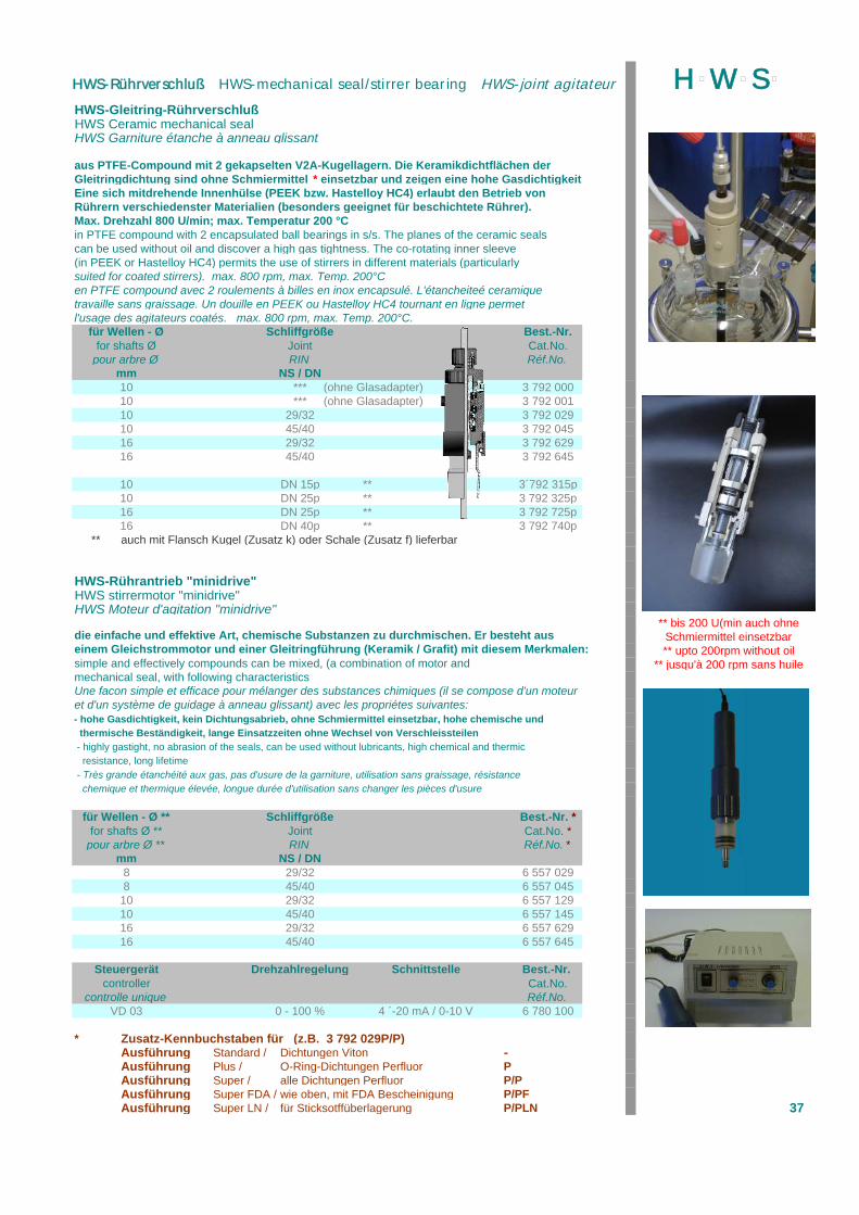
HWS-Gleitring-RührverschlußHWS Ceramic mechanical seal HWS Garniture étanche à anneau glissant
aus PTFE-Compound mit 2 gekapselten V2A-Kugellagern. Die Keramikdichtflächen derGleitringdichtung sind ohne Schmiermittel * einsetzbar und zeigen eine hohe GasdichtigkeitEine sich mitdrehende Innenhülse (PEEK bzw. Hastelloy HC4) erlaubt den Betrieb vonRührern verschiedenster Materialien (besonders geeignet für beschichtete Rührer).Max. Drehzahl 800 U/min; max. Temperatur 200 °Cin PTFE compound with 2 encapsulated ball bearings in s/s. The planes of the ceramic sealscan be used without oil and discover a high gas tightness. The co-rotating inner sleeve(in PEEK or Hastelloy HC4) permits the use of stirrers in different materials (particularlysuited for coated stirrers). max. 800 rpm, max. Temp. 200°Cen PTFE compound avec 2 roulements à billes en inox encapsulé. L'étancheiteé ceramiquetravaille sans graissage. Un douille en PEEK ou Hastelloy HC4 tournant en ligne permetl'usage des agitateurs coatés. max. 800 rpm, max. Temp. 200°C.
für Wellen - Ø Schliffgröße Best.-Nr.for shafts Ø Joint Cat.No.
pour arbre Ø RIN Réf.No.mm NS / DN10 *** (ohne Glasadapter) 3 792 00010 *** (ohne Glasadapter) 3 792 00110 29/32 3 792 02910 45/40 3 792 04516 29/32 3 792 62916 45/40 3 792 645
10 DN 15p ** 3´792 315p10 DN 25p ** 3 792 325p16 DN 25p ** 3 792 725p16 DN 40p ** 3 792 740p
** auch mit Flansch Kugel (Zusatz k) oder Schale (Zusatz f) lieferbar
HWS-Rührantrieb "minidrive"HWS stirrermotor "minidrive"HWS Moteur d'agitation "minidrive"
** bis 200 U(min auch ohnedie einfache und effektive Art, chemische Substanzen zu durchmischen. Er besteht aus Schmiermittel einsetzbareinem Gleichstrommotor und einer Gleitringführung (Keramik / Grafit) mit diesem Merkmalen: ** upto 200rpm without oilsimple and effectively compounds can be mixed, (a combination of motor and ** jusqu'à 200 rpm sans huilemechanical seal, with following characteristicsUne facon simple et efficace pour mélanger des substances chimiques (il se compose d'un moteuret d'un système de guidage à anneau glissant) avec les propriétes suivantes:- hohe Gasdichtigkeit, kein Dichtungsabrieb, ohne Schmiermittel einsetzbar, hohe chemische und thermische Beständigkeit, lange Einsatzzeiten ohne Wechsel von Verschleissteilen - highly gastight, no abrasion of the seals, can be used without lubricants, high chemical and thermic resistance, long lifetime - Très grande étanchéité aux gas, pas d'usure de la garniture, utilisation sans graissage, résistance chemique et thermique élevée, longue durée d'utilisation sans changer les pièces d'usure
für Wellen - Ø ** Schliffgröße Best.-Nr. *for shafts Ø ** Joint Cat.No. *
pour arbre Ø ** RIN Réf.No. *mm NS / DN
8 29/32 6 557 0298 45/40 6 557 045
10 29/32 6 557 12910 45/40 6 557 14516 29/32 6 557 62916 45/40 6 557 645
Steuergerät Drehzahlregelung Schnittstelle Best.-Nr. controller Cat.No.
controlle unique Réf.No.VD 03 0 - 100 % 4 ´-20 mA / 0-10 V 6 780 100
* Zusatz-Kennbuchstaben für (z.B. 3 792 029P/P)Ausführung Standard / Dichtungen Viton -Ausführung Plus / O-Ring-Dichtungen Perfluor PAusführung Super / alle Dichtungen Perfluor P/PAusführung Super FDA / wie oben, mit FDA Bescheinigung P/PFAusführung Super LN / für Sticksotffüberlagerung P/PLN 37
H þW þS þHWS-Rührverschluß HWS-mechanical seal/stirrer bearing HWS-joint agitateur
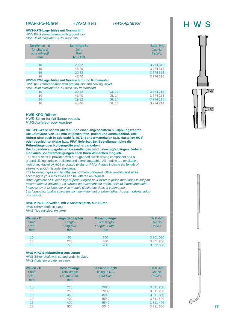
HWS-KPG-Lagerhülse mit NormschliffHWS KPG stirrer bearing with ground jointHWS Joint d'agitateur KPG avec RIN
für Wellen - Ø Schliffgröße Best.-Nr.for shafts Ø Joint Cat.No.
pour arbre Ø RIN Réf.No.mm NS / DN
10 29/32 3 774 31210 45/40 3 774 31416 29/32 3 774 31516 45/40 3 774 316
HWS-KPG-Lagerhülse mit Normschliff und KühlmantelHWS KPG stirrer bearing with ground joint and cooling jacketHWS Joint d'agitateur KPG avec RIN et manchon
10 29/32 GL 14 3 774 21210 45/40 GL 14 3 774 21316 29/32 GL 14 3 774 21516 45/40 GL 14 3 774 214
HWS-KPG-RührerHWS-Stirrer for flat flange vesselsHWS-Agitateur pour réacteur
Die KPG-Welle hat am oberen Ende einen angeschliffenen Kupplungszapfen.Die Lauffläche von 160 mm ist geschliffen, poliert und austauschbar. AlleRührer sind auch in Edelstahl (1.4571) Sondermaterialien (z.B. Hastelloy HC4)oder beschichtet (Halar bzw. PFA) lieferbar. Bei Bestellungen bitte dieRührerlänge oder Kolbengröße und -art angeben.Die folgenden angegebenen Gesamtlängen sind bevorzugte Längen. Jedochsind auch Sonderanfertigungen nach Ihren Wünschen möglich.The stirrer shaft is provided with a roughened clutch driving component and aground sliding surface, polished and interchangeable. All models are available innichrome, Hastelloy HC4 or coated (Halar or PFA). Please indicate the length ofstirrers to avoid misunderstandings.The following types and lengths are normally preferred. Other models and sizesaccording to your indications can bei offered on request.Arbre agitateur KPG avec tige superieur rigide pour éviter le glisse ment dans le supportraccord moteur agitateur. La surface de roulement est rodée, polie et interchangeable.Indiquez s.v.p. la longueur et le modèle d'agitateur dans la commande.Les longueurs totales suivantes sont normalement préférentielles. Autres modèles selonvos besoin.
HWS-KPG-Rührwellen, mit 2 Ansatzzapfen, aus DuranHWS Stirrer shaft, in glassHWS Tige rectifiée, en verre
Wellen - Ø Länge der Zapfen Gesamtllänge Best.-Nr.Shaft Length Total length Cat.No.Arbre Longueur Longueur total Réf.No.mm mm mm
10 50 260 3 801 05010 200 460 3 801 20016 50 260 3 802 050
HWS-KPG-Einblattrührer aus DuranHWS Stirrer shaft with curved ends, in glassHWS-Agitateur à pale, en verre
Wellen - Ø Gesamtlänge passend für NS Best.-Nr.Shaft Total length fitting to NS Cat.No.Arbre Longueur tot. pour RIN Réf.No.mm mm
10 250 19/26 3 811 25010 280 29/32 3 811 28010 350 45/40 3 811 35010 400 45/40 3 811 40016 400 45/40 3 811 40616 500 60/46 3 811 506 38
H þW þS þHWS-KPG-Rührer HWS-Stirrers HWS-Agitateur
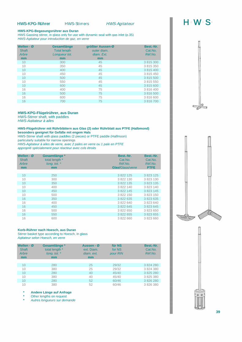
HWS-KPG-Begasungsrührer aus DuranHWS Gassing stirrer, in glass only for use with dynamic seal with gas inlet (p.35)HWS-Agitateur pour introduction de gaz, en verre
Wellen - Ø Gesamtlänge größter Aussen-Ø Best.-Nr.Shaft Total length outer diam. Cat.No.Arbre Longueur tot. diam. Ext. Réf.No.mm mm mm10 300 45 3 815 30010 350 45 3 815 35010 400 45 3 815 40010 450 45 3 815 45010 500 45 3 815 50010 550 45 3 815 55010 600 45 3 815 60016 400 75 3 816 40016 500 75 3 816 50016 600 75 3 816 60016 700 75 3 816 700
HWS-KPG-Flügelrührer, aus DuranHWS-Stirrer shaft, with paddlesHWS-Agitateur à ailes
HWS-Flügelrührer mit Rührblättern aus Glas (2) oder Rührblatt aus PTFE (Halbmond)besonders geeignet für Gefäße mit engem HalsHWS-Stirrer shaft with glass paddles (2 pieces) or PTFE paddle (Halfmoon)particularly suitable for narrow openingsHWS-Agitateur à ailes de verre, avec 2 pales en verre ou 1 pale en PTFEapproprié spécialement pour réacteur avec cols étroits
Wellen - Ø Gesamtlänge * Best.-Nr. Best.-Nr.Shaft total length * Cat.No. Cat.No.Arbre long. tot. * Réf.No. Réf.No.mm mm Glas/Glass/verre PTFE
10 250 3 822 125 3 823 12510 300 3 822 130 3 823 13010 350 3 822 135 3 823 13510 400 3 822 140 3 823 14010 450 3 822 145 3 823 14510 500 3 822 150 3 823 15016 350 3 822 635 3 823 63516 400 3 822 640 3 823 64016 450 3 822 645 3 823 64516 500 3 822 650 3 823 65016 550 3 822 655 3 823 65516 600 3 822 660 3 823 660
Korb-Rührer nach Hoesch, aus DuranStirrer basket type according to Hoesch, in glassAgitateur selon Hoesch, en verre
Wellen - Ø Gesamtlänge * Aussen - Ø für NS Best.-Nr.Shaft total length * ext. Diam. for NS Cat.No.Arbre long. tot. * diam. ext. pour RIN Réf.No.mm mm mm
10 280 25 29/32 3 824 28010 380 25 29/32 3 824 38010 280 40 45/40 3 825 28010 380 40 45/40 3 825 38010 280 52 60/46 3 826 28010 380 52 60/46 3 826 380
* Andere Länge auf Anfrage* Other lengths on request* Autres longueurs sur demande
39
H þW þS þHWS-KPG-Rührer HWS-Stirrers HWS-Agitateur
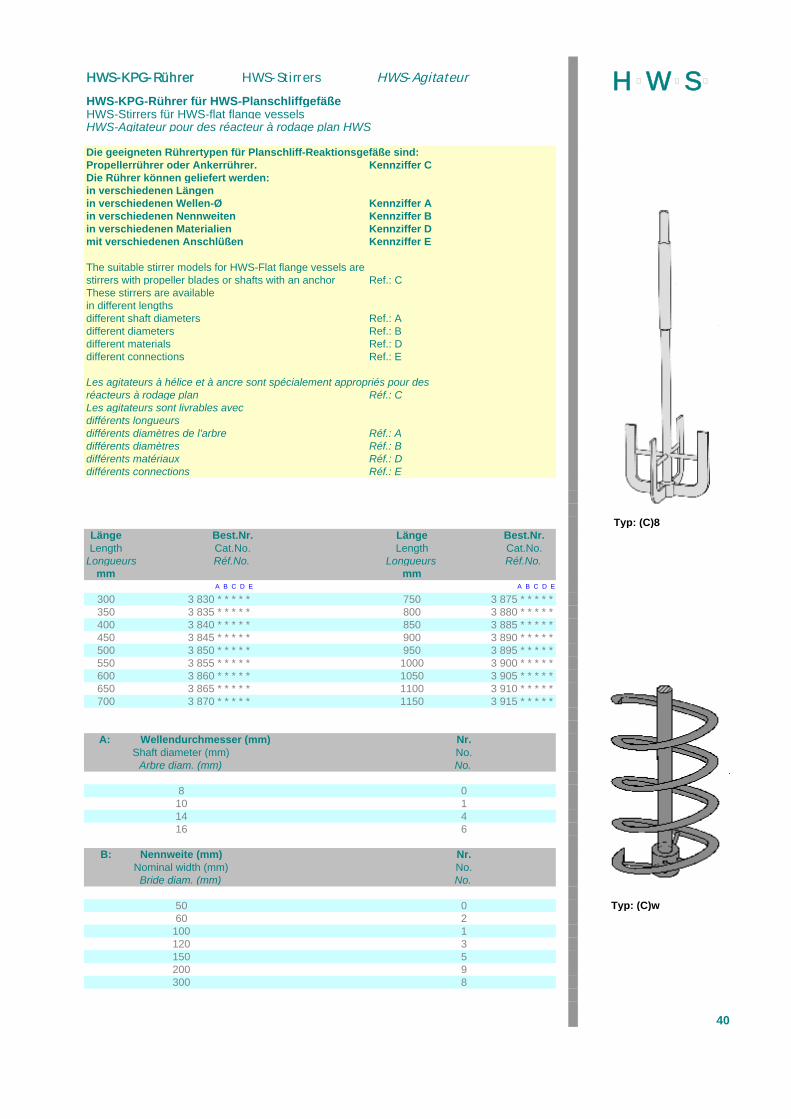
HWS-KPG-Rührer für HWS-PlanschliffgefäßeHWS-Stirrers für HWS-flat flange vesselsHWS-Agitateur pour des réacteur à rodage plan HWS
Die geeigneten Rührertypen für Planschliff-Reaktionsgefäße sind:Propellerrührer oder Ankerrührer. Kennziffer CDie Rührer können geliefert werden:in verschiedenen Längenin verschiedenen Wellen-Ø Kennziffer Ain verschiedenen Nennweiten Kennziffer Bin verschiedenen Materialien Kennziffer Dmit verschiedenen Anschlüßen Kennziffer E
The suitable stirrer models for HWS-Flat flange vessels arestirrers with propeller blades or shafts with an anchor Ref.: CThese stirrers are availablein different lengthsdifferent shaft diameters Ref.: Adifferent diameters Ref.: Bdifferent materials Ref.: Ddifferent connections Ref.: E
Les agitateurs à hélice et à ancre sont spécialement appropriés pour desréacteurs à rodage plan Réf.: CLes agitateurs sont livrables avecdifférents longueursdifférents diamètres de l'arbre Réf.: Adifférents diamètres Réf.: Bdifférents matériaux Réf.: Ddifférents connections Réf.: E
Typ: (C)8Länge Best.Nr. Länge Best.Nr.Length Cat.No. Length Cat.No.
Longueurs Réf.No. Longueurs Réf.No.mm mm
A B C D E A B C D E
300 3 830 * * * * * 750 3 875 * * * * *350 3 835 * * * * * 800 3 880 * * * * *400 3 840 * * * * * 850 3 885 * * * * *450 3 845 * * * * * 900 3 890 * * * * *500 3 850 * * * * * 950 3 895 * * * * *550 3 855 * * * * * 1000 3 900 * * * * *600 3 860 * * * * * 1050 3 905 * * * * *650 3 865 * * * * * 1100 3 910 * * * * *700 3 870 * * * * * 1150 3 915 * * * * *
A: Wellendurchmesser (mm) Nr.Shaft diameter (mm) No.
Arbre diam. (mm) No.
8 010 114 416 6
B: Nennweite (mm) Nr.Nominal width (mm) No.Bride diam. (mm) No.
50 0 Typ: (C)w60 2
100 1120 3150 5200 9300 8
40
H þW þS þHWS-KPG-Rührer HWS-Stirrers HWS-Agitateur
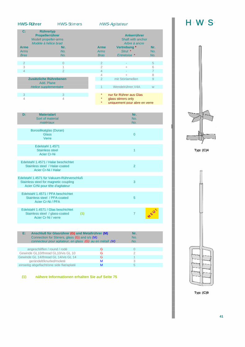
C: RührertypPropellerrührer Ankerrührer
Modell propeller-arms Shaft with anchorModèle à hélice brad Arbre à ancre
Arme Nr. Arme Vertrebung * Nr.Arms No. Arms Strut * No.Bras No. Bras Entretoise * No.
2 0 2 - 53 1 2 + 64 2 4 - 7
4 + 8Zusätzliche Rührebenen 2 mit Störlamellen 9
Add. PlaneHelice supplementaire 1 Wendelrührer,V4A w
3 3 * nur für Rührer aus Glas4 4 * glass stirrers only
* uniquement pour abre en verre
D: Materialart Nr.Sort of material No.
matériaux No. U
Borosilikatglas (Duran)Glass 0Verre
Edelstahl 1.4571Stainless steel 1 Typ: (C)4
Acier Cr-Ni
Edelstahl 1.4571 / Halar beschichtetStainless steel / Halar-coated 2
Acier Cr-Ni / Halar
Edelstahl 1.4571 für Vakuum-RührverschlußStainless steel for magnetic coupling 3
Acier CrNi pour tête d'agitateur
Edelstahl 1.4571 / PFA beschichtetStainless steel / PFA-coated 5
Acier Cr-Ni / PFA
Edelstahl 1.4571 / Glas beschichtetStainless steel / glass-coated (1) 7
Acier Cr-Ni / verre
E: Anschluß für Glasrührer (G) und Metallrührer (M) Nr.Connection for Stirrers, glass (G) and s/s (M) No.connecteur pour agitateur, en glass (G) au en métall (M) No.
angeschliffen / round / rodé G 0Gewinde GL10/thread GL10/vis GL 10 G 2
Gewinde GL 14/thread GL 14/vis GL 14 G 1gerändelt/knurled/moleté M 3
einseitig abgeflacht/one side flat/aplaté M 5
(1) nähere Informationen erhalten Sie auf Seite 75
Typ: (C)9
41
H þW þS þHWS-Rührer HWS-Stirrers HWS-Agitateur
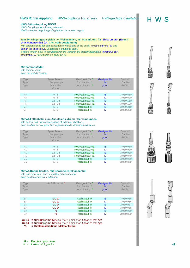
HWS-Rührerkupplung DBGMHWS-Couplings for stirrers, patentedHWS-système de guidage d'agitation sur moteur, reg.int
zum Schwingungsausgleich der Wellenenden, mit Spannfutter, für Elektromotor (E) undDruckluftanschluß (D), CrNi-Stahl-Ausführungwith torsion spring for compensation of vibrations of the shaft, electric stirrers (E) andcompr.-air stirrers (D). Execution in stainless steel.à faible torsion pour le compensation de vibration du moteur d'agitation électrique (E) ,air comptr. (D ).Exécution en acier Cr-Ni.
Mit Torsionsfederwith torsion springavec ressort de torsion
Typ Spannbereich Geeignet für * Geeignet für Best.-Nr.Type clamp range for direction * for Cat.No.Type Diam. Ext. pour direction * pour Réf.No.
Ø mm
RF 6 - 8 Rechts/Links, R/L E 3 950 010RF 6 - 8 Rechts/Links, R/L D 3 950 020RF 12 - 14 Rechts/Links, R/L E 3 950 110RF 12 - 14 Rechts/Links, R/L D 3 950 120CF 5 - 9 Rechtslauf, R E 3 950 210CF 5 - 9 Rechtslauf, R D 3 950 220
Mit VA-Faltenbalg, zum Ausgleich extremer Schwingungenwith bellow, VA, for compensation of extreme vibrationsavec soufflet en VA, pour la compensation de vibrations extremes
Typ Spannbereich Geeignet für * Geeignet für Best.-Nr.Type clamp range for direction * for Cat.No.Type Diam. Ext. pour direction * pour Réf.No.
Ø mm
RV 6 - 8 Rechts/Links, R/L E 3 950 910RV 6 - 8 Rechts/Links, R/L D 3 950 920RV 12 - 14 Rechts/Links, R/L E 3 950 930RV 12 - 14 Rechts/Links, R/L D 3 950 940CV 5 - 9 Rechtslauf, R E 3 950 950CV 5 - 9 Rechtslauf, R D 3 950 960
Mit VA-Doppelkardan, mit Gewinde-Direktanschlußwith universal joint, and screw thread connectionavec cardan et vis pour adaption
Typ für Rührer mit * Geeignet für * Geeignet für Best.-Nr.Type for direction * for Cat.No.Type pour direction * pour Réf.No.
EK GL 10 Rechtslauf, R E 3 950 985EK GL 10 Rechtslauf, R D 3 950 986EK GL 14 Rechtslauf, R E 3 950 987EK GL 14 Rechtslauf, R D 3 950 988EK *1 Rechtslauf, R E 3 950 989EK *1 Rechtslauf, R D 3 950 990
GL 10 = für Rührer mit KPG 10 / for 10 mm shaft / pour 10 mm tigeGL 14 = für Rührer mit KPG 16 / for 16 mm shaft / pour 16 mm tige
*1 = Direktanschluß für Edelstahlrührer
* R = Rechts / right / droite* L = Links / left / gauche 42
H þW þS þHWS-Rührerkupplung HWS-couplings for stirrers HWS-guidage d‘agitation

HWS-Rührwellenschutz DBGM *HWS-Shaft protection for stirrers *HWS-Protection de tige agitateurs *
HWS-Rührwellenschutz aus Polycarbonat (Makrolon, Lexan o.ä.), transparent,längenverstellbar von 190 - 310, bis 330 - 600 mm,rund: Oberteil Aussen-Ø 70 mm, Innenteil Aussen-Ø 60 mmgerade: Breite 100 bzw. 200 mmeinfachste Montage durch Bajonett-Schnellkupplung mit Universal-Montagering,zum nachträglichen festen Anbau an viele Laborrührwerke, Preßluftrührer.
HWS-Shaft protection in polycarbonat (Makrolon, Lexan o.ä.)axial adjustment range 190 - 310 mm or 220 - 340 mm (max. 440 mm)
HWS-Protection en polycarbonate, réglage dans une longueur de 190 - 310 ou 220 - 340 mm (max. 440 mm)
Länge Best.-Nr.length Cat.No.
longueur Réf.No.mm
Halbschalen-Ausführung mit PP-UniversalringHalf-shell execution with universal mounting ring ** 190 - 310 3 995 000Construction monocoque demie avec bague pour le montage
dto., mit Stativstab aus CrNi-Stahldto., with support rod in stainless steel ** 190 - 310 3 995 100dto., avec tige de serrage en avier Cr-Ni
dto., Ersatz, ohne Haltering oder Stativstabdto., replacement, without ring or support rod ** 190 - 310 3 995 001dto.,
Halbschalen-Ausführung mit PP-UniversalringHalf-shell execution with universal mounting ring ** 220 - 340 3 995 300Construction monocoque demie avec bague pour le montage
dto., mit Stativstab aus CrNi-Stahldto., with support rod in stainless steel ** 220 - 340 3 995 310dto., avec tige de serrage en avier Cr-Ni
dto., Ersatz, ohne Haltering oder Stativstabdto., replacement, without ring or support rod ** 220 - 340 3 995 320dto.,
Vollrohr-Ausführung mit UniversalringTube execution with universal mounting ring 220 - 340 3 996 000Tube modèle avec bague pour le montage
dto., mit Stativstab aus CrNi-Stahldto., with support rod in stainless steel 220 - 340 3 996 100dto., avec tige de serrage en avier Cr-Ni
Gerade Ausführung, mit Stativstab aus CrNi-Stahlplate with support rod in stainless steel B=100mm 185 - 310 3 997 100Protection avec tige de serrage
Gerade Ausführung, mit Stativstab aus CrNi-Stahlplate with support rod in stainless steel B=200mm 330 - 600 3 997 200Protection avec tige de serrage
** auch in Ausführung "Plexiglas" lieferbar
* entspricht den geforderten Sicherheits-Vorschriften der BG Chemie* according to the requirements of the German empolyers liability insurance company* selon les demandes de la casse allemande de prévoyance contre les accidents
43
H þW þS þHWS-Rührwellenschutz HWS-Shaft protection HWS-Protection de tige
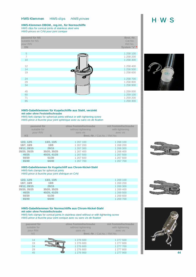
HWS-Klemmen DBGM., reg.int., für NormschliffeHWS clips for conical joints of stainless steel wireHWS-pinces en CrNi pour joint conique
passend für NS Best.-Nr.suitable for NS Cat.No.pour RIN Réf.No.
DN System "s" *
5 1 258 1007 1 258 200
10 1 258 300
12 1 258 40014 1 258 50019 1 258 600
24 1 258 70029 1 258 80034 1 258 900
45 1 259 00060 1 259 10071 1 259 20085 1 259 300
HWS-Gabelklemmen für Kugelschliffe aus Stahl, verzinktmit oder ohne FeststellschraubeHWS-fork clamps for spherical joints without or with tightening screwHWS-pince à fourche pour joint sphérique avec ou sans vis de fixation
passend für ohne Feststellschraube mit Feststellschraubesuitable for without tightening with tighteningpour RIN sans vis avec vis
KS S Best.-Nr. / Cat.No. / Réf.No.
12/2, 12/5 13/2, 13/5 1 267 100 1 268 10018/7, 18/9 19/9 1 267 200 1 268 200
28/12, 28/15 29/15 1 267 300 1 268 30035/20, 35/25 35/20, 35/25 1 267 400 1 268 400
40/25 40/25, 41/25 1 267 500 1 267 50050/30 51/30 1 267 600 1 267 60065/40 64/40 1 267 700 1 267 700
HWS-Gabelklemmen für Kugelschliff aus Chrom-Nickel-StahlHWS-fork clamps for spherical joints HWS-pince à fourche pour joint shérique en CrNi
12/2, 12/5 13/2, 13/5 1 269 10018/7, 18/9 19/9 1 269 200
28/12, 28/15 29/15 1 269 30035/20, 35/25 35/20, 35/25 1 269 400
40/25 40/25, 41/25 1 269 50050/30 51/30 1 269 60065/40 64/40 1 269 700
HWS-Gabelklemmen für Normschliffe aus Chrom-Nickel-Stahlmit oder ohne FeststellschraubeHWS-fork clamps for conical joints in stainless steel without or with tightening screwHWS-pince à fourche pour joint conique avec ou sans vis de fixation
passend für ohne Feststellschraube mit Feststellschraubesuitable for without tightening with tighteningpour RIN sans vis avec vis
NS Best.-Nr. / Cat.No. / Réf.No.
14 1 276 500 1 277 50019 1 276 600 1 277 60024 1 276 600 1 277 70029 1 276 800 1 277 80045 1 276 900 1 277 900 44
H þW þS þHWS-Klemmen HWS-clips HWS-pinces
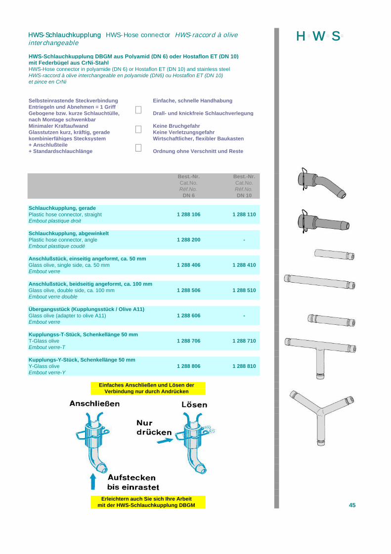
HWS-Schlauchkupplung DBGM aus Polyamid (DN 6) oder Hostaflon ET (DN 10)mit Federbügel aus CrNi-StahlHWS-Hose connector in polyamide (DN 6) or Hostaflon ET (DN 10) and stainless steelHWS-raccord à olive interchangeable en polyamide (DN6) ou Hostaflon ET (DN 10)et pince en CrNi
Selbsteinrastende Steckverbindung Einfache, schnelle HandhabungEntriegeln und Abnehmen = 1 GriffGebogene bzw. kurze Schlauchtülle, Drall- und knickfreie Schlauchverlegungnach Montage schwenkbarMinimaler Kraftaufwand Keine BruchgefahrGlasstutzen kurz, kräftig, gerade Keine Verletzungsgefahrkombinierfähiges Stecksystem Wirtschaftlicher, flexibler Baukasten+ Anschlußteile+ Standardschlauchlänge Ordnung ohne Verschnitt und Reste
Best.-Nr. Best.-Nr.Cat.No. Cat.No.Réf.No. Réf.No.
DN 6 DN 10
Schlauchkupplung, geradePlastic hose connector, straight 1 288 106 1 288 110Embout plastique droit
Schlauchkupplung, abgewinkeltPlastic hose connector, angle 1 288 200 -Embout plastique coudé
Anschlußstück, einseitig angeformt, ca. 50 mmGlass olive, single side, ca. 50 mm 1 288 406 1 288 410Embout verre
Anschlußstück, beidseitig angeformt, ca. 100 mmGlass olive, double side, ca. 100 mm 1 288 506 1 288 510Embout verre double
Übergangsstück (Kupplungsstück / Olive A11)Glass olive (adapter to olive A11) 1 288 606 -Embout verre
Kupplungss-T-Stück, Schenkellänge 50 mmT-Glass olive 1 288 706 1 288 710Embout verre-T
Kupplungs-Y-Stück, Schenkellänge 50 mmY-Glass olive 1 288 806 1 288 810Embout verre-Y
Einfaches Anschließen und Lösen derVerbindung nur durch Andrücken
Erleichtern auch Sie sich Ihre Arbeitmit der HWS-Schlauchkupplung DBGM 45
H þW þS þHWS-Schlauchkupplung HWS-Hose connector HWS-raccord à oliveinterchangeable
þþ
þ

HWS-SchraubschlauchkupplungHWS-Hose connection, straight or bentHWS-Raccord pour embout verre fileté
zum Anschluß von Schläuchen an Glasgewinde (GL), Olive aus PP oder PTFE
Größe Kappe* Olive* Best.-Nr.Size Cap* Oliv* Cat.No.
Filetage Capouchon* Olive* Réf.No.GL
Ausführung: gerade / straight / droit14 PBT PTFE 1 289 11414 PBT PP 1 289 31414 PTFE-Compound PTFE 1 289 51418 PBT PTFE 1 289 11818 PBT PP 1 289 31818 PTFE-Compound PTFE 1 289 518
Ausführung: gebogen / bent / coudè14 PBT PTFE 1 289 21414 PBT PP 1 289 41414 PTFE-Compound PTFE 1 289 61418 PBT PTFE 1 289 21818 PBT PP 1 289 41818 PTFE-Compound PTFE 1 289 618
*verwendete Materialien TemperaturbereichPP = Polypropylen von -40 bis +140 °CPBT = Polybutylenterephthalat von -45 bis +200 °CPTFE = Polytetraflourethylen von -200 bis +260 °C
Silikonschlauch, 55° Shore A, transparentEinsatzbereich von -60 °C ... +180 °C, kurzzeitig +260 °CSilicone hose, transparent, operation range -60 °C ...+180 °C, max. 260 °CTube silicone, translucide, blanc, gamme de temp. -60 °C... +180°C, max. 260 °C
Innen - Ø Außen - Ø Best.-Nr. Inner Ø Outer Ø Cat.No. Ø int. Ø ext. Réf.No. mm mm
8 12 1 299 0019 13 1 299 002
10 14 1 299 00311 15 1 299 00412 16 1 299 00513 17 1 299 00614 18 1 299 00715 19 1 299 00816 20 1 299 009
Viton-Schlauch, schwarz, Einsatzbereich von -20 °C... +200 °CViton hose, black, operation range -20 °C... +200 °CTube viton, opaque, noir, gamme de températur -20 °C... +200 °C
8 12 1 299 0119 13 1 299 012
10 14 1 299 01311 15 1 299 01412 16 1 299015
PTFE-Schlauch, Einsatzbereich von -20 °C... +200 °CPTFE hose, operation range -20 °C... +200 °CTube PTFE, gamme de températur -20 °C... +200 °C
8 10 1 299 10810 12 1 299 11012 14 1 299 11214 16 1 299 11416 18 1 299 116
46
H þW þS þHWS-Klemmen HWS-clips HWS-pinces
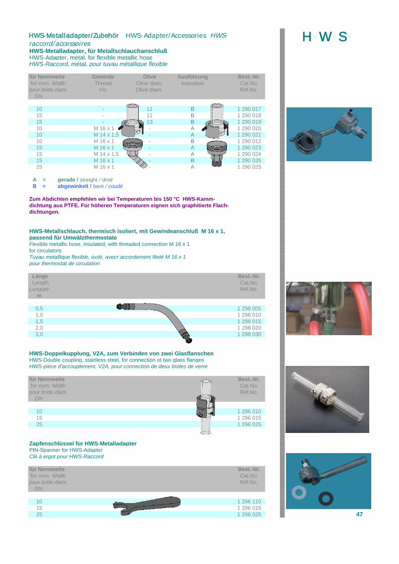
HWS-Metalladapter, für MetallschlauchanschlußHWS-Adapter, metal, for flexible metallic hoseHWS-Raccord, métal, pour tuyau métallique flexible
für Nennweite Gewinde Olive Ausführung Best.-Nr. for nom. Width Thread Olive diam. execution Cat.No.pour bride.diam. Vis Olive diam. Réf.No.
DN
10 - 11 B 1 290 01715 - 11 B 1 290 01815 - 13 B 1 290 01910 M 16 x 1 - A 1 290 02010 M 14 x 1,5 - A 1 290 02110 M 16 x 1 - B 1 290 01215 M 16 x 1 - A 1 290 02315 M 14 x 1,5 - A 1 290 02415 M 16 x 1 - B 1 290 03525 M 16 x 1 - A 1 290 025
A = gerade / streight / droitB = abgewinkelt / bent / coudé
Zum Abdichten empfehlen wir bei Temperaturen bis 150 °C HWS-Kamm-dichtung aus PTFE. Für höheren Temperaturen eignen sich graphitierte Flach-dichtungen.
HWS-Metallschlauch, thermisch isoliert, mit Gewindeanschluß M 16 x 1,passend für UmwälzthermostateFlexible metallic hose, insulated, with threaded connection M 16 x 1for circulatorsTuyau metallique flexible, isolé, avecr accordement fileté M 16 x 1pour thermostat de circulation
Länge Best.-Nr. Length Cat.No.Longuer Réf.No.
m
0,5 1 298 0051,0 1 298 0101,5 1 298 0152,0 1 298 0203,0 1 298 030
HWS-Doppelkupplung, V2A, zum Verbinden von zwei GlasflanschenHWS-Double coupling, stainless steel, for connection ot two glass flangesHWS-pièce d'accouplement, V2A, pour connection de deux brides de verre
für Nennweite Best.-Nr. for nom. Width Cat.No.pour bride.diam. Réf.No.
DN
10 1 296 01015 1 296 01525 1 296 025
Zapfenschlüssel für HWS-MetalladapterPIN-Spanner for HWS-AdapterClé à ergot pour HWS-Raccord
für Nennweite Best.-Nr. for nom. Width Cat.No.pour bride.diam. Réf.No.
DN
10 1 296 11015 1 296 01525 1 296 025 47
H þW þS þHWS-Metalladapter/Zubehör HWS-Adapter/Accessories HWS-raccord/accessoires
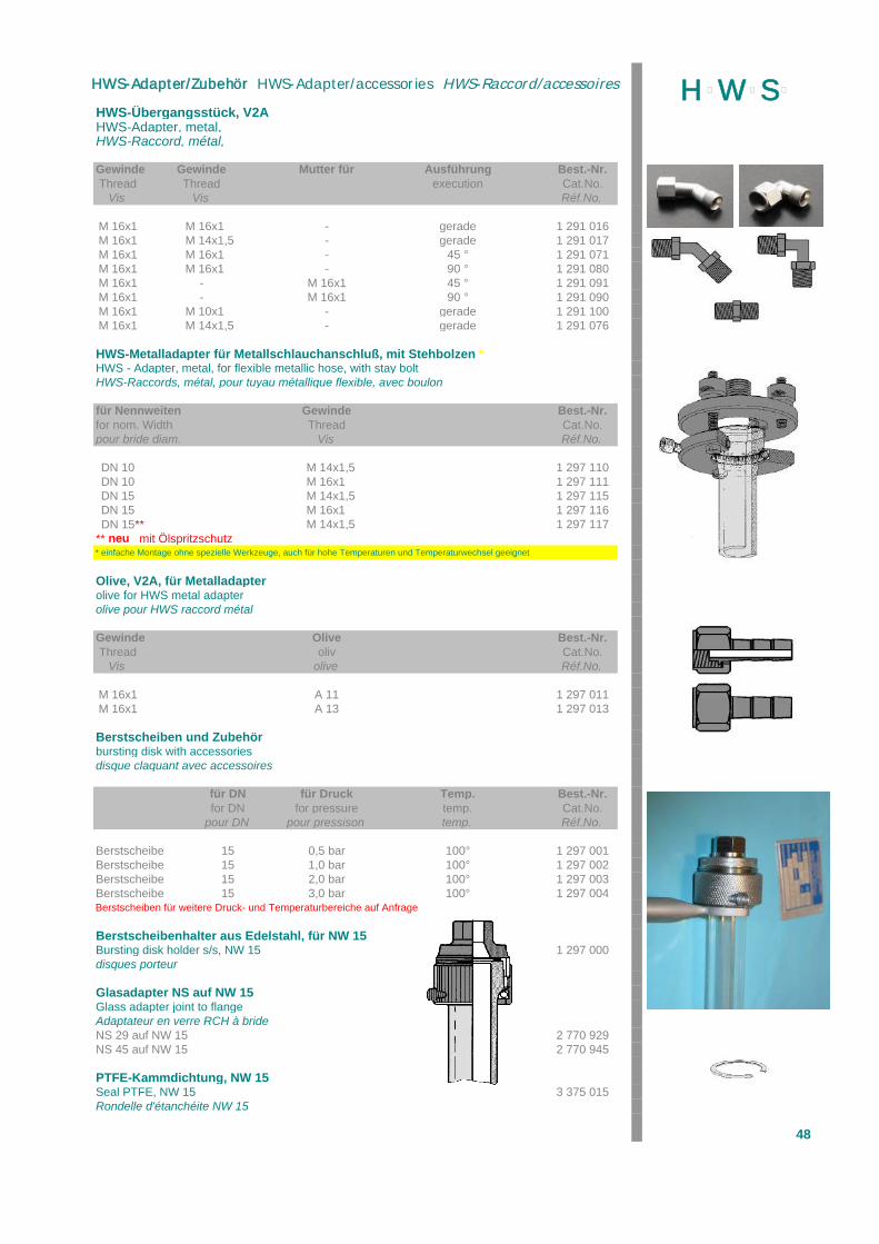
HWS-Übergangsstück, V2AHWS-Adapter, metal, HWS-Raccord, métal,
Gewinde Gewinde Mutter für Ausführung Best.-Nr.Thread Thread execution Cat.No.
Vis Vis Réf.No.
M 16x1 M 16x1 - gerade 1 291 016M 16x1 M 14x1,5 - gerade 1 291 017M 16x1 M 16x1 - 45 ° 1 291 071M 16x1 M 16x1 - 90 ° 1 291 080M 16x1 - M 16x1 45 ° 1 291 091M 16x1 - M 16x1 90 ° 1 291 090M 16x1 M 10x1 - gerade 1 291 100M 16x1 M 14x1,5 - gerade 1 291 076
HWS-Metalladapter für Metallschlauchanschluß, mit Stehbolzen *HWS - Adapter, metal, for flexible metallic hose, with stay bolt HWS-Raccords, métal, pour tuyau métallique flexible, avec boulon
für Nennweiten Gewinde Best.-Nr.for nom. Width Thread Cat.No.pour bride diam. Vis Réf.No.
DN 10 M 14x1,5 1 297 110DN 10 M 16x1 1 297 111DN 15 M 14x1,5 1 297 115DN 15 M 16x1 1 297 116
DN 15** M 14x1,5 1 297 117** neu mit Ölspritzschutz* einfache Montage ohne spezielle Werkzeuge, auch für hohe Temperaturen und Temperaturwechsel geeignet
Olive, V2A, für Metalladapterolive for HWS metal adapterolive pour HWS raccord métal
Gewinde Olive Best.-Nr.Thread oliv Cat.No.
Vis olive Réf.No.
M 16x1 A 11 1 297 011M 16x1 A 13 1 297 013
Berstscheiben und Zubehörbursting disk with accessoriesdisque claquant avec accessoires
für DN für Druck Temp. Best.-Nr.for DN for pressure temp. Cat.No.
pour DN pour pressison temp. Réf.No.
Berstscheibe 15 0,5 bar 100° 1 297 001Berstscheibe 15 1,0 bar 100° 1 297 002Berstscheibe 15 2,0 bar 100° 1 297 003Berstscheibe 15 3,0 bar 100° 1 297 004Berstscheiben für weitere Druck- und Temperaturbereiche auf Anfrage
Berstscheibenhalter aus Edelstahl, für NW 15Bursting disk holder s/s, NW 15 1 297 000disques porteur
Glasadapter NS auf NW 15Glass adapter joint to flangeAdaptateur en verre RCH à brideNS 29 auf NW 15 2 770 929NS 45 auf NW 15 2 770 945
PTFE-Kammdichtung, NW 15Seal PTFE, NW 15 3 375 015Rondelle d'étanchéite NW 15
48
H þW þS þHWS-Adapter/Zubehör HWS-Adapter/accessories HWS-Raccord/accessoires
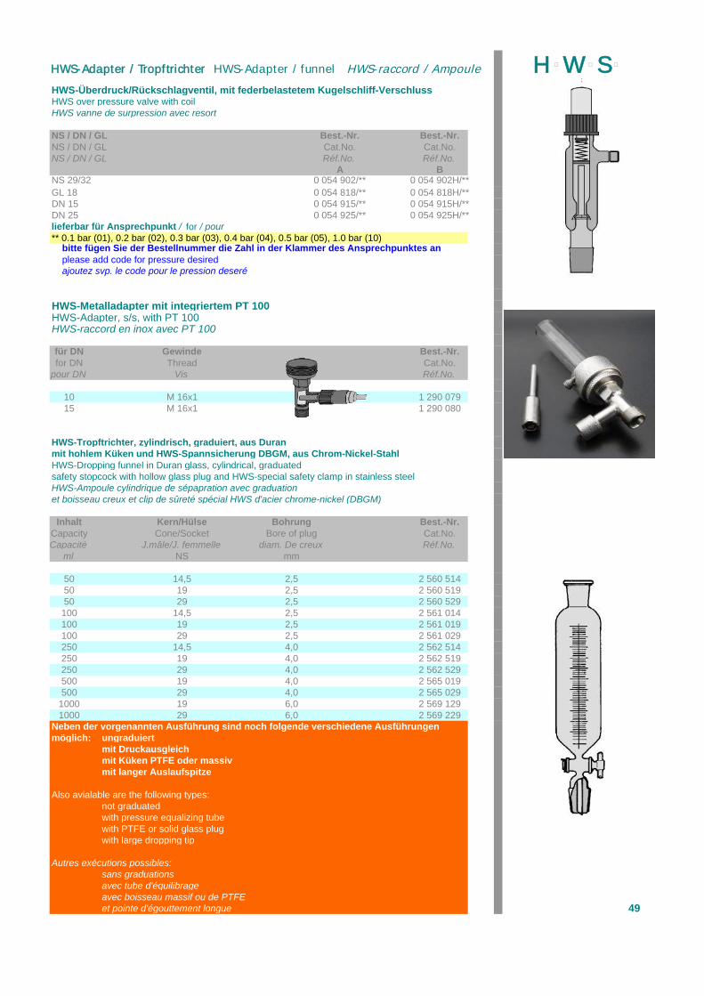
HWS-Überdruck/Rückschlagventil, mit federbelastetem Kugelschliff-VerschlussHWS over pressure valve with coilHWS vanne de surpression avec resort
NS / DN / GL Best.-Nr. Best.-Nr.NS / DN / GL Cat.No. Cat.No.NS / DN / GL Réf.No. Réf.No.
A BNS 29/32 0 054 902/** 0 054 902H/**GL 18 0 054 818/** 0 054 818H/**DN 15 0 054 915/** 0 054 915H/**DN 25 0 054 925/** 0 054 925H/**lieferbar für Ansprechpunkt / for / pour** 0.1 bar (01), 0.2 bar (02), 0.3 bar (03), 0.4 bar (04), 0.5 bar (05), 1.0 bar (10) bitte fügen Sie der Bestellnummer die Zahl in der Klammer des Ansprechpunktes an please add code for pressure desired ajoutez svp. le code pour le pression deseré
HWS-Metalladapter mit integriertem PT 100HWS-Adapter, s/s, with PT 100HWS-raccord en inox avec PT 100
für DN Gewinde Best.-Nr.for DN Thread Cat.No.
pour DN Vis Réf.No.
10 M 16x1 1 290 07915 M 16x1 1 290 080
HWS-Tropftrichter, zylindrisch, graduiert, aus Duranmit hohlem Küken und HWS-Spannsicherung DBGM, aus Chrom-Nickel-StahlHWS-Dropping funnel in Duran glass, cylindrical, graduatedsafety stopcock with hollow glass plug and HWS-special safety clamp in stainless steelHWS-Ampoule cylindrique de sépapration avec graduationet boisseau creux et clip de sûreté spécial HWS d'acier chrome-nickel (DBGM)
Inhalt Kern/Hülse Bohrung Best.-Nr.Capacity Cone/Socket Bore of plug Cat.No.Capacité J.mâle/J. femmelle diam. De creux Réf.No.
ml NS mm
50 14,5 2,5 2 560 51450 19 2,5 2 560 51950 29 2,5 2 560 529100 14,5 2,5 2 561 014100 19 2,5 2 561 019100 29 2,5 2 561 029250 14,5 4,0 2 562 514250 19 4,0 2 562 519250 29 4,0 2 562 529500 19 4,0 2 565 019500 29 4,0 2 565 029
1000 19 6,0 2 569 1291000 29 6,0 2 569 229
Neben der vorgenannten Ausführung sind noch folgende verschiedene Ausführungenmöglich: ungraduiert
mit Druckausgleichmit Küken PTFE oder massivmit langer Auslaufspitze
Also avialable are the following types:not graduatedwith pressure equalizing tubewith PTFE or solid glass plugwith large dropping tip
Autres exécutions possibles:sans graduationsavec tube d'équilibrageavec boisseau massif ou de PTFEet pointe d'égouttement longue 49
H þW þS þHWS-Adapter / Tropftrichter HWS-Adapter / funnel HWS-raccord / Ampoule
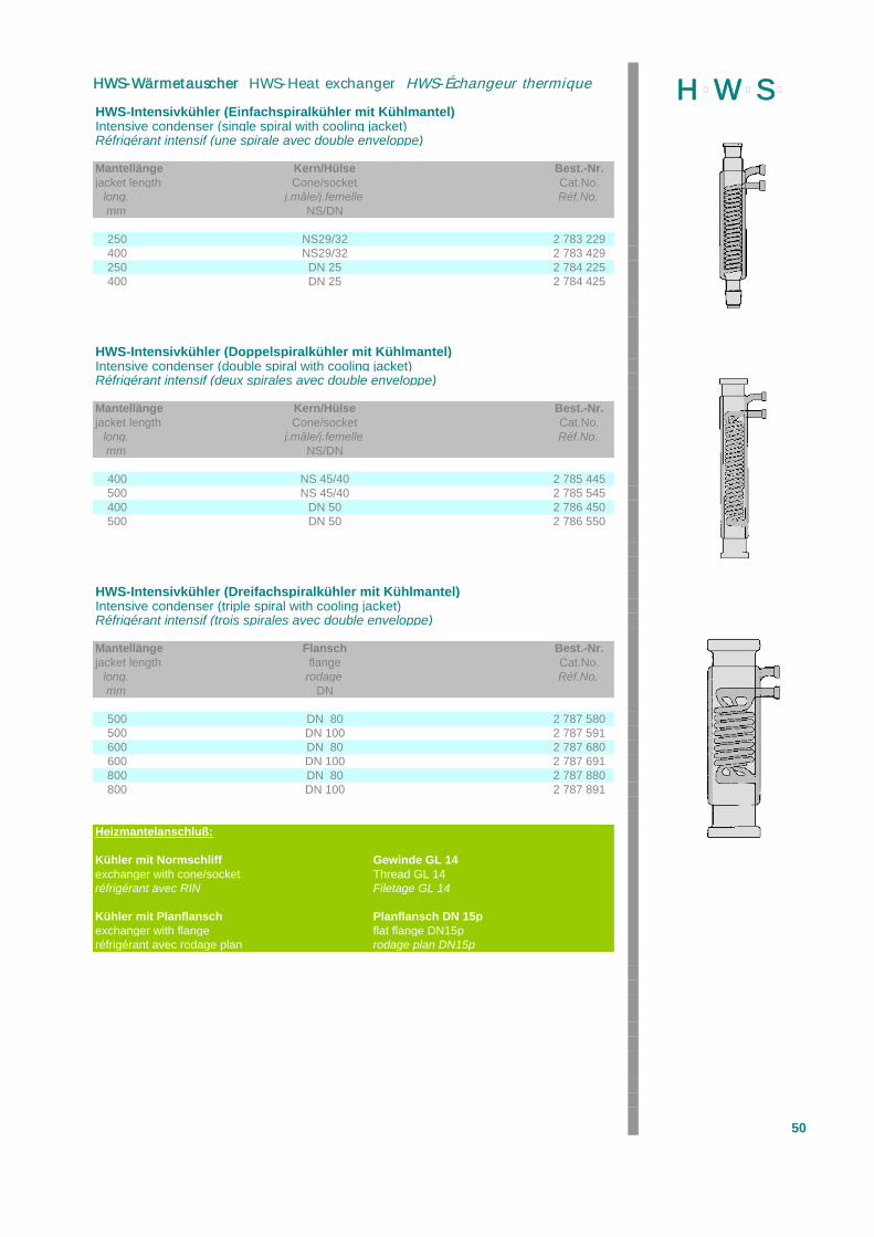
HWS-Intensivkühler (Einfachspiralkühler mit Kühlmantel)Intensive condenser (single spiral with cooling jacket)Réfrigérant intensif (une spirale avec double enveloppe)
Mantellänge Kern/Hülse Best.-Nr.jacket length Cone/socket Cat.No.
long. j.mâle/j.femelle Réf.No.mm NS/DN
250 NS29/32 2 783 229400 NS29/32 2 783 429250 DN 25 2 784 225400 DN 25 2 784 425
HWS-Intensivkühler (Doppelspiralkühler mit Kühlmantel)Intensive condenser (double spiral with cooling jacket)Réfrigérant intensif (deux spirales avec double enveloppe)
Mantellänge Kern/Hülse Best.-Nr.jacket length Cone/socket Cat.No.
long. j.mâle/j.femelle Réf.No.mm NS/DN
400 NS 45/40 2 785 445500 NS 45/40 2 785 545400 DN 50 2 786 450500 DN 50 2 786 550
HWS-Intensivkühler (Dreifachspiralkühler mit Kühlmantel)Intensive condenser (triple spiral with cooling jacket)Réfrigérant intensif (trois spirales avec double enveloppe)
Mantellänge Flansch Best.-Nr.jacket length flange Cat.No.
long. rodage Réf.No.mm DN
500 DN 80 2 787 580500 DN 100 2 787 591600 DN 80 2 787 680600 DN 100 2 787 691800 DN 80 2 787 880800 DN 100 2 787 891
Heizmantelanschluß:
Kühler mit Normschliff Gewinde GL 14exchanger with cone/socket Thread GL 14réfrigérant avec RIN Filetage GL 14
Kühler mit Planflansch Planflansch DN 15pexchanger with flange flat flange DN15préfrigérant avec rodage plan rodage plan DN15p
50
H þW þS þHWS-Wärmetauscher HWS-Heat exchanger HWS-Échangeur thermique
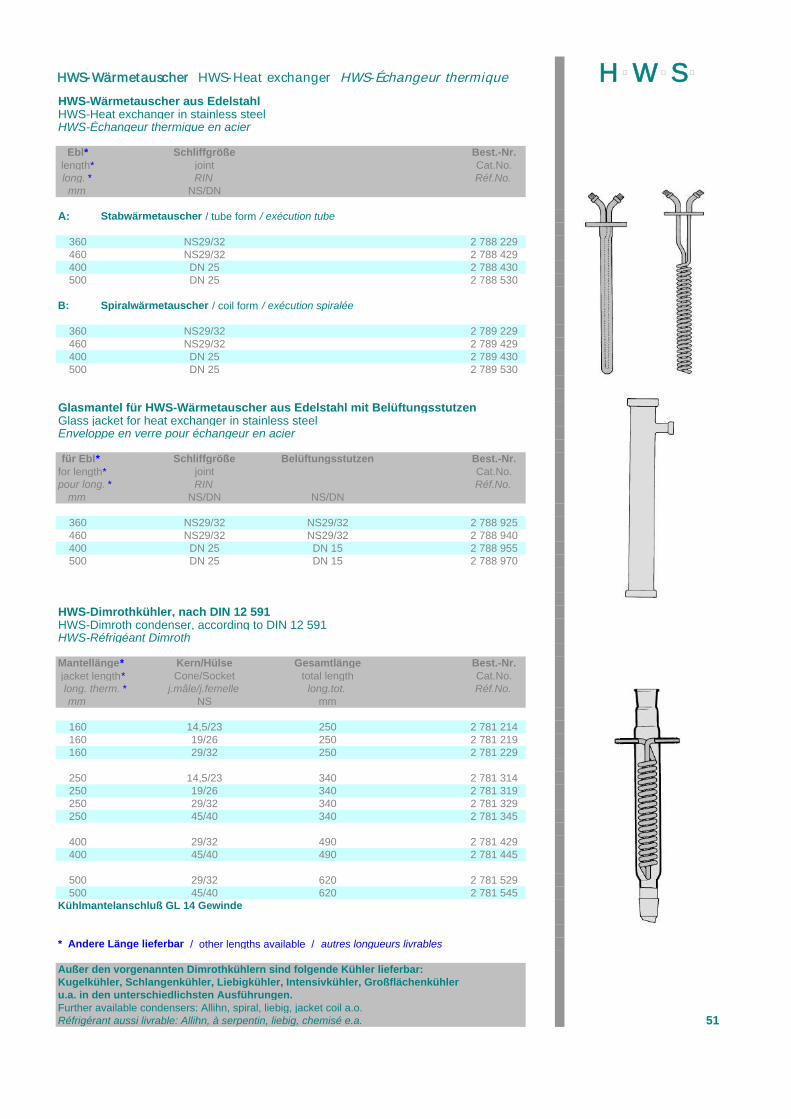
HWS-Wärmetauscher aus EdelstahlHWS-Heat exchanger in stainless steelHWS-Échangeur thermique en acier
Ebl* Schliffgröße Best.-Nr.length* joint Cat.No.long. * RIN Réf.No.mm NS/DN
A: Stabwärmetauscher / tube form / exécution tube
360 NS29/32 2 788 229460 NS29/32 2 788 429400 DN 25 2 788 430500 DN 25 2 788 530
B: Spiralwärmetauscher / coil form / exécution spiralée
360 NS29/32 2 789 229460 NS29/32 2 789 429400 DN 25 2 789 430500 DN 25 2 789 530
Glasmantel für HWS-Wärmetauscher aus Edelstahl mit BelüftungsstutzenGlass jacket for heat exchanger in stainless steelEnveloppe en verre pour échangeur en acier
für Ebl* Schliffgröße Belüftungsstutzen Best.-Nr.for length* joint Cat.No.pour long. * RIN Réf.No.
mm NS/DN NS/DN
360 NS29/32 NS29/32 2 788 925460 NS29/32 NS29/32 2 788 940400 DN 25 DN 15 2 788 955500 DN 25 DN 15 2 788 970
HWS-Dimrothkühler, nach DIN 12 591HWS-Dimroth condenser, according to DIN 12 591HWS-Réfrigéant Dimroth
Mantellänge* Kern/Hülse Gesamtlänge Best.-Nr. jacket length* Cone/Socket total length Cat.No. long. therm. * j.mâle/j.femelle long.tot. Réf.No.
mm NS mm
160 14,5/23 250 2 781 214160 19/26 250 2 781 219160 29/32 250 2 781 229
250 14,5/23 340 2 781 314250 19/26 340 2 781 319250 29/32 340 2 781 329250 45/40 340 2 781 345
400 29/32 490 2 781 429400 45/40 490 2 781 445
500 29/32 620 2 781 529500 45/40 620 2 781 545
Kühlmantelanschluß GL 14 Gewinde
* Andere Länge lieferbar / other lengths available / autres longueurs livrables
Außer den vorgenannten Dimrothkühlern sind folgende Kühler lieferbar:Kugelkühler, Schlangenkühler, Liebigkühler, Intensivkühler, Großflächenkühleru.a. in den unterschiedlichsten Ausführungen.Further available condensers: Allihn, spiral, liebig, jacket coil a.o.Réfrigérant aussi livrable: Allihn, à serpentin, liebig, chemisé e.a. 51
H þW þS þHWS-Wärmetauscher HWS-Heat exchanger HWS-Échangeur thermique
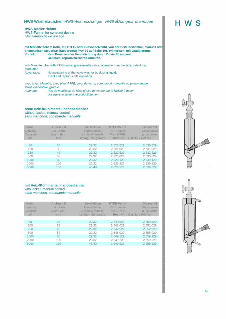
HWS-DosiertrichterHWS-Funnel for constant dosingHWS-Ampoule de dosage
mit Mariotte'schem Rohr, mit PTFE- oder Glasnadelventil, von der Seite bedienbar, manuell oderpneumatisch steuerbar (Steuergerät PAV 90 auf Seite 10), zylindrisch, mit Graduierung.Vorteil: Kein Benetzen der Ventildichtung durch Dosierflüssigkeit.
Genaues, reproduzierbares Arbeiten.
with Mariotte tube, with PTFE-valve, glass-needle valve, operable from the side, cylindrical,graduatedAdvantage: No moistening of the valve washer by dosing liquid,
exact and reproducible operation
avec tuyau Mariotte, avec pivot PTFE, pivot de verre, commandé manuelle ou pneumatique,forme cylindrique, graduéAvantage: Pas de mouillage de l'étancheité de vanne par le liquide à doser,
dosage exactement reproductiblement
ohne Heiz-/Kühlmantel, handbedienbarwithout jacket, manual controlsans manchon, commande manuelle
Inhalt Außen - Ø Kern/Hülse PTFE-Ventil GlasventilCapacity Ext. Diam. Cone/Socket PTFE-valve Glass-valveCapacité Diam. Ext. J.mâle/J.femelle Pivot PTFE p. de verre
ml mm schräg NS gerade Best.-Nr. / Cat.No. / Réf.No.
50 34 29/32 2 620 529 2 630 529100 38 29/32 2 621 029 2 631 029250 48 29/32 2 622 529 2 632 529500 58 29/32 2 625 029 2 635 029
1000 80 29/32 2 629 129 2 639 1292000 100 29/32 2 629 229 2 639 2295000 150 45/40 2 629 529 2 639 529
mit Heiz-/Kühlmantel, handbedienbarwith jacket, manual controlavec manchon, commande manuelle
Inhalt Außen - Ø Kern/Hülse PTFE-Ventil GlasventilCapacity Ext. Diam. Cone/Socket PTFE-valve Glass-valveCapacité Diam. Ext. J.mâle/J.femelle Pivot PTFE p. de verre
ml mm schräg NS gerade Best.-Nr. / Cat.No. / Réf.No.
50 34 29/32 2 640 529 2 650 529100 38 29/32 2 641 029 2 651 029250 48 29/32 2 642 529 2 652 529500 58 29/32 2 645 029 2 655 029
1000 80 29/32 2 649 129 2 659 1292000 100 29/32 2 649 229 2 659 2295000 150 45/40 2 649 529 2 659 529
52
H þW þS þHWS-Wärmetauscher HWS-Heat exchanger HWS-Échangeur thermique
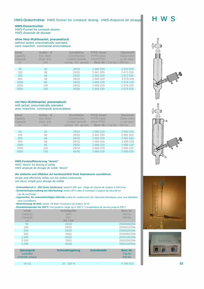
HWS-DosiertrichterHWS-Funnel for constant dosingHWS-Ampoule de dosage
ohne Heiz-/Kühlmantel, pneumatischwithout jacket, pneumatically operatedsans manchon, commande pneumatique
Inhalt Außen - Ø Kern/Hülse PTFE-Ventil GlasventilCapacity Ext. Diam. Cone/Socket PTFE-valve Glass-valveCapacité Diam. Ext. J.mâle/J.femelle Pivot PTFE p. de verre
ml mm schräg NS gerade Best.-Nr. / Cat.No. / Réf.No.
50 34 29/32 2 660 529 2 670 529100 38 29/32 2 661 029 2 671 029250 48 29/32 2 662 529 2 672 529500 58 29/32 2 665 029 2 675 029
1000 80 29/32 2 669 129 2 679 1292000 100 29/32 2 669 229 2 679 2295000 150 45/40 2 669 529 2 679 529
mit Heiz-/Kühlmantel, pneumatischwith jacket, pneumatically operatedavec manchon, commande pneumatique
Inhalt Außen - Ø Kern/Hülse PTFE-Ventil GlasventilCapacity Ext. Diam. Cone/Socket PTFE-valve Glass-valveCapacité Diam. Ext. J.mâle/J.femelle Pivot PTFE p. de verre
ml mm schräg NS gerade Best.-Nr. / Cat.No. / Réf.No.
50 34 29/32 2 680 529 2 690 529100 38 29/32 2 681 029 2 691 029250 48 29/32 2 682 529 2 692 529500 58 29/32 2 685 029 2 695 029
1000 80 29/32 2 689 129 2 699 1292000 100 29/32 2 689 229 2 699 2295000 150 45/40 2 689 529 2 699 529
HWS-Feststoffdosierung "dosini"HWS "dosini" for dosing of solidsHWS ampoule de dosage de solide "dosini"
die einfache und effektive Art kontinuierlich feste Substanzen zuzuführen.simple and effectively solids can bei added continouslyune facon simple pour dosage de solilde
- Drehzahlberich 0 - 250 U/min (stufenlos) / speed 0-250 rpm - Plage de vitesse de rotation 0-250 tr/mn- Sicherheitsabschaltung bei Überlastung / switch off in case of overload / Coupure de sécurité en
cas de surcharge- eigensicher, für unbeaufsichtigten Betrieb / suited for unobserved use / Sécurité intrinsèaue, pour une utilisation
sans surveillance- Motorleistung 18 Watt / power 18 Watt / Puissance de moteur 18 W- Einsatztemperatur bis 200°C / the perulvce range up to 200°C / Température de service jusqu'à 200°C
Inhalt Schliffgröße Best.-Nr. Capacity Joint Cat.No. Capacité RIN Réf.No.
ml NS / DN50 29/32 2500005/29A
100 29/32 2500010/29A250 29/32 2500025/29A500 2932 2500050/29A
1.000 29/32 2500100/29A2.000 2932 2500200/29A5.000 45/40 2500100/45A
Steuergerät Drehzahlregelung Schnittstelle Best.-Nr. controller Cat.No.
controlle unique Réf.No.
VD 01 10 - 100 % - 6 780 010 53
H þW þS þHWS-Dosiertrichter HWS-Funnel for constant dosing HWS-Ampoule de dosage
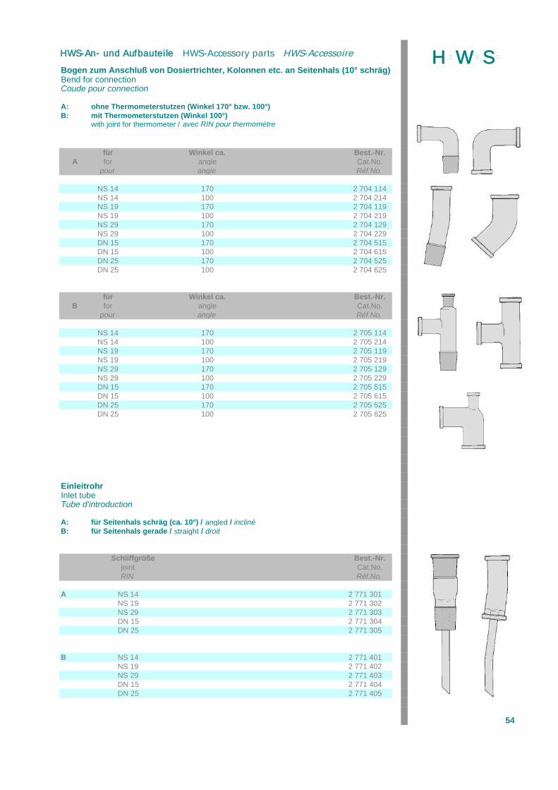
Bogen zum Anschluß von Dosiertrichter, Kolonnen etc. an Seitenhals (10° schräg)Bend for connectionCoude pour connection
A: ohne Thermometerstutzen (Winkel 170° bzw. 100°)B: mit Thermometerstutzen (Winkel 100°)
with joint for thermometer / avec RIN pour thermométre
für Winkel ca. Best.-Nr.A for angle Cat.No.
pour angle Réf.No.
NS 14 170 2 704 114NS 14 100 2 704 214NS 19 170 2 704 119NS 19 100 2 704 219NS 29 170 2 704 129NS 29 100 2 704 229DN 15 170 2 704 515DN 15 100 2 704 615DN 25 170 2 704 525DN 25 100 2 704 625
für Winkel ca. Best.-Nr.B for angle Cat.No.
pour angle Réf.No.
NS 14 170 2 705 114NS 14 100 2 705 214NS 19 170 2 705 119NS 19 100 2 705 219NS 29 170 2 705 129NS 29 100 2 705 229DN 15 170 2 705 515DN 15 100 2 705 615DN 25 170 2 705 525DN 25 100 2 705 625
EinleitrohrInlet tubeTube d'introduction
A: für Seitenhals schräg (ca. 10°) / angled / inclinéB: für Seitenhals gerade / straight / droit
Schliffgröße Best.-Nr.joint Cat.No.RIN Réf.No.
A NS 14 2 771 301NS 19 2 771 302NS 29 2 771 303DN 15 2 771 304DN 25 2 771 305
B NS 14 2 771 401NS 19 2 771 402NS 29 2 771 403DN 15 2 771 404DN 25 2 771 405
54
H þW þS þHWS-An- und Aufbauteile HWS-Accessory parts HWS-Accessoire

Aufsatz mit Olive (Gewinde)Adapter with olive (thread)Adaptateur avec olive (filetage)
A: gerade Ausführung / straight / droitB: abgewinkelt 90° / angled / incliné
A B Schliffgröße Olive* Best.-Nr. Best.-Nr.
joint Oliv* Cat.No. Cat.No.RIN olive * Réf.No. Réf.No.
NS 14 A 11 2 770 014 2 770 114NS 19 A 11 2 770 019 2 770 119NS 19 A 13 2 770 020 2 770 120MS 29 A 13 2 770 029 2 770 129NS 29 A 16 2 770 030 2 770 130DN 15 A 13 2 770 055 2 770 155DN 15 A 16 2 770 060 2 770 160DN 25 A 16 2 770 075 2 770 175DN 25 A 19 2 770 080 2 770 180
* Auch mit GL-Gewinde lieferbar.* with screw thread available, too* aussi livrable avec GL
Aufsatz mit Hahn und Gewinde GL 14**Adapter with stopcock und screw thread GL 14**Adaptateur avec robinet et filetage GL **
A: gerade Ausführung / straight / droitB: abgewinkelt 90° / angled / incliné
A B Schliffgröße Bohrung Ø mm Best.-Nr. Best.-Nr.
joint bore Ø mm Cat.No. Cat.No.RIN passage Ø mm Réf.No. Réf.No.
NS 14 2,5 2 770 214 2 770 514NS 19 2,5 2 770 219 2 770 519NS 29 2,5 2 770 229 2 770 529DN 15 2,5 2 770 255 2 770 555NS 19 4 2 770 319 2 770 619NS 29 4 2 770 329 2 770 629DN 15 4 2 770 355 2 770 655DN 25 6 2 770 460 2 770 660
** Auch mit GL-Gewinde GL 18 oder GL 25 lieferbar** with screw thread GL 18 and GL 25 available, too** aussi livrable avec GL 18 ou GL 25
Verschlußstopfen und -kappenClosing stoppers and capsBouchon et capouchon
Schliffgröße Best.-Nr.joint Cat.No.RIN Réf.No.
NS 14 2 100 014NS 19 Verschlußstopfen 2 100 019NS 29 NS = closing stoppers 2 100 029NS 45 Bouchon 2 100 045DN 10 2 100 310DN 15 2 100 315DN 25 Verschlußkappe 2 100 325DN 40 DN = closing caps 2 100 340DN 50 capouchon 2 100 350DN 80 2 100 380
55
H þW þS þHWS-An- und Aufbauteile HWS-Accessory parts PAV 90 HWS-Accessoire
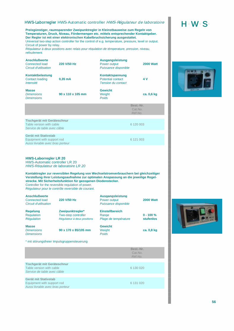
Preisgünstiger, raumsparender Zweipunktregler in Kleinstbauweise zum Regeln vonTemperaturen, Druck, Niveau, Fördermengen etc. mittels entsprechender Kontaktgeber.Der Regler ist mit einer elektronischen Kabelbruchsicherung ausgestattet.Universal two-step action controller for the control of e.g. temperature, pressure, level or output.Circuit of power by relay.Régulateur à deux positions avec relais pour régulation de témperature, pression, niveau,refoulement.
Anschlußwerte AusgangsleistungConnected load 220 V/50 Hz Power output 2000 WattCircuit d'utilisation Puissance disponible
Kontaktbelastung KontaktspannungContact loading 0,35 mA Potential contact 4 VIntensité Tension du contact
Masse GewichtDimensions 90 x 110 x 105 mm Weight ca. 0,6 kgDimensions Poids
Best.-Nr.Cat.No.Réf.No.
Tischgerät mit GeräteschnurTable version with cable 6 120 003Service de table avec câble
Gerät mit StativstabEquipment with support rod 6 121 003Aussi livrable avec bras porteur
HWS-Laborregler LR 20HWS-Automatic controller LR 20HWS-Régulateur de laboratoire LR 20
Kontaktregler zur reversiblen Regelung von Wechselstromverbrauchern bei gleichzeitigerVerstellung ihrer Leistungsaufnahme zur optimalen Anspassung an die jeweilige Regel-strecke. Mit Sicherheitsfunktion für gezogenen Diodenstecker.Controller for the reversible regulation of power.Régulateur pour le contrôle reversible de courant.
Anschlußwerte AusgangsleistungConnected load 220 V/50 Hz Power output 2000 WattCircuit d'utilisation Puissance disponible
Regelung Zweipunktregler* EinstellbereichRegulation Two-step controller Range 0 - 100 %Régulation Régulateur à deux positions Plage de température stufenlos
Masse GewichtDimensions 90 x 170 x 85/105 mm Weight ca. 0,8 kgDimensions Poids
* mit störungsfreier Impulsgruppensteuerung
Best.-Nr.Cat.No.Réf.No.
Tischgerät mit GeräteschnurTable version with cable 6 130 020Service de table avec câble
Gerät mit StativstabEquipment with support rod 6 131 020Aussi livrable avec bras porteur
56
H þW þS þHWS-Laborregler HWS-Automatic controller HWS-Régulateur de laboratoire
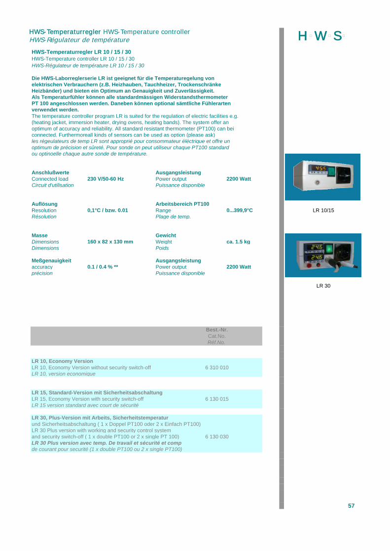
HWS-Temperaturregler LR 10 / 15 / 30HWS-Temperature controller LR 10 / 15 / 30HWS-Régulateur de température LR 10 / 15 / 30
Die HWS-Laborreglerserie LR ist geeignet für die Temperaturegelung von elektrischen Verbrauchern (z.B. Heizhauben, Tauchheizer, TrockenschränkeHeizbänder) und bieten ein Optimum an Genauigkeit und Zuverlässigkeit.Als Temperaturfühler können alle standardmässigen WiderstandsthermometerPT 100 angeschlossen werden. Daneben können optional sämtliche Fühlerartenverwendet werden.The temperature controller program LR is suited for the regulation of electric facilities e.g.(heating jacket, immersion heater, drying ovens, heating bands). The system offer anoptimum of accuracy and reliability. All standard resistant thermometer (PT100) can beiconnected. Furthermoreall kinds of sensors can be used as option (please ask)les régeulateurs de temp LR sont approprié pour consommateur éléctrique et offre unoptimum de précision et sûreté. Pour sonde on peut utiliseur chaque PT100 standardou optinoelle chaque autre sonde de température.
Anschlußwerte AusgangsleistungConnected load 230 V/50-60 Hz Power output 2200 WattCircuit d'utilisation Puissance disponible
Auflösung Arbeitsbereich PT100Resolution 0,1°C / bzw. 0.01 Range 0...399,9°C LR 10/15Résolution Plage de temp.
Masse GewichtDimensions 160 x 82 x 130 mm Weight ca. 1.5 kgDimensions Poids
Meßgenauigkeit Ausgangsleistungaccuracy 0.1 / 0.4 % ** Power output 2200 Wattprécision Puissance disponible
LR 30
Best.-Nr.Cat.No.Réf.No.
LR 10, Economy VersionLR 10, Economy Version without security switch-off 6 310 010LR 10, version economique
LR 15, Standard-Version mit SicherheitsabschaltungLR 15, Economy Version with security switch-off 6 130 015LR 15 version standard avec court de sécurité
LR 30, Plus-Version mit Arbeits, Sicherheitstemperaturund Sicherheitsabschaltung ( 1 x Doppel PT100 oder 2 x Einfach PT100)LR 30 Plus version with working and security control systemand security switch-off ( 1 x double PT100 or 2 x single PT 100) 6 130 030LR 30 Plus version avec temp. De travail et sécurité et compde courant pour securité (1 x double PT100 ou 2 x single PT100)
57
H þW þS þHWS-Temperaturregler HWS-Temperature controller HWS-Régulateur de température

HWS-Rücklaufsteuergerät RS 04HWS-Reflux Controller RS 04HWS-commandeur de destillation RS 04
zur Rücklaufsteuergerät bei Kolonnendestillationen, einstellbares Mengen-verhältnis von 1 : 999 bis 999 : 1 Sekunden.Funktionswahlmöglichkeit: Automatik, totaler Rücklauf, tolale Destillations-abnahme.Siedegrenzkontrolle durch PT 100 und/oder Kontaktgeber, digitale Anzeigeder Grenzwerttemperatur (Soll / Ist), Wahlmöglichkeit für Siedekontrolle:Automatik / blockiert mit separat abschaltbarem akustischem Signal beiGrenzwertüberschreitung.Schnittstelle für externe Steuerung, Ausgabe von Temperatur, Intervallenund Schaltpunkten.Datendokumentation mit Zeitangabe (optional).
is used during distillation for an adjustable ratio of reflux and outlet between1 : 999 to 999 : 1 seconds.Functions: Automatic, reflux, outlet of distillateControl of set points by PT 100 or contact-thermometer, digital display oftemperature, even with acoustic signal.for external PC.
est utilisée pendant la destillation pour le ratio de reflux et écoulemententre 1 : 999 et 999 : 1 sec.Function: Automatique, reflux compl., écoulement compl.Contrôle per PT 100 on thermomètre à contact.
Anschlußwerte NennaufnahmeConnected load 230 V/50 Hz Rated power 27 WattCircuit d'utilisation Prise de courant
Funkentstörgrad GrundtaktElimination of interference N nach VDE 0875 timing pulse rate 1 sElimination de brouillage cycle
Ausgang für Magnet KontaktbelastungOutput for magnet 24 V /1,5 A Contact loading 5 mAtension de sortie pour magnet Intensité
Masse GewichtDimensions 210 x 130 x 150 mm Weight ca. 3,8 kgDimensions Poids
Best.-Nr.Cat.No.Réf.No.
Tischgerät mit GeräteschnurTable version with cable 6 400 000Service de table avec câble
Magnetmagnet 6 400 002magnet
Kabel für Magnetcable for magnet 6 400 003cable pour magnet
Magnethalter für Ø 60 mmmagnet holder for Ø 60 mm * 6 401 060fixation à magnet pour Ø 60 mm
Widerstandsthermometer PT 100 /EdelstahlPT 100 Ebl 80 mm, Ø 6mm 6 810 806PT 100
* auch in anderen Ø lieferbar
58
H þW þS þHWS-Rücklaufsteuergerrät HWS-Reflux Controller HWS-commander de destillation
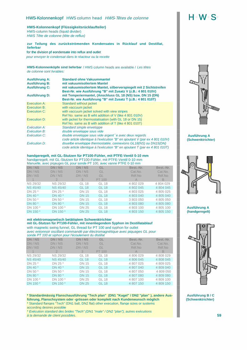
HWS-Kolonnenkopf (Flüssigkeitsrücklaufteiler)HWS-column heads (liquid divider)HWS Tête de colonne (tête de reflux)
HWS-Kolonnenköpfe sind lieferbar / HWS column heads are available / Les têtesde colonne sont livrables:
Ausführung A: Standard ohne VakuummantelAusführung B: mit vakuumisoliertem MantelAusführung C: mit vakuumisoliertem Mantel, silberverspiegelt mit 2 Sichtstreifen
Best-Nr. wie Ausführung "B" mit Zusatz V (z.B.: 4 801 010V)Ausführung D: mit Temperiermantel, (Anschluss GL 18 (NS) bzw. DN 15 (DN)
Best-Nr. wie Ausführung "B" mit Zusatz T (z.B.: 4 801 010T)Execution A: Standard without jacketExecution B: with vaccuum jacketExecution C: with vaccuum jacket solved with view stripes
Ref No. same as B wiht addition of V (like 4 801 010V)Execution D: with jacket for thermostatisation (with GL 18 or DN 15)
Ref No. same as B with addition of T (like 4 801 010T)Exécution A: Standard simple enveloppeExécution B: double enveloppe sous videExécution C: double enveloppe sous vide argent´´e avec deux regards Ausführung A
code article identique à l'exécution "B" en ajoutant V (par ex 4 801 010V) (Schwenktrichter)Exécution D: douelbe enveloppe thermostatée, connexions GL18(NS) ou DN15(DN)
code article identique à l'exécution "B" en ajoutant T (par ex 4 801 010T)
handgeregelt, mit GL-Stutzen für PT100-Fühler, mit PTFE-Ventil 0-10 mmhandgeregelt, mit GL-Stutzen für PT100-Fühler, mit PTFE-Ventil 0-10 mmManuelle, avec piqauges GL pour sonde PT 100, avec vanne PTFE 0-10 mmDN / NS DN / NS DN / NS GL Best.-Nr. Best.-Nr.DN / NS DN / NS DN / NS GL Cat.No. Cat.No.DN / NS DN / NS DN / NS GL Réf.No Réf.No
1 2 3 PT 100 A BNS 29/32 NS 29/32 GL 18 GL 18 4 802 029 4 804 029 NS 45/40 NS 45/40 GL 18 GL 18 4 802 045 4 804 045DN 25 * DN 25 * DN 15 GL 18 4 803 025 4 805 025DN 40 * DN 40 * DN 15 GL 18 4 803 040 4 805 040DN 50 * DN 50 * DN 15 GL 18 3 803 050 4 805 050DN 80 * DN 80 * DN 15 GL 18 4 803 080 4 805 080DN 100 * DN 100 * DN 25 GL 18 4 803 100 4 805 100 Ausführung ADN 150 * DN 150 * DN 25 GL 18 4 803 150 4 805 150 (handgeregelt)
mit elektromagnetisch betätigtem Schwenktrichtermit GL-Stutzen für PT100-Fühler, mit innenliegendem Syphon im Destillatablaufwith magnetic swing funnel, GL thread for PT 100 and syphon for outletavec entonnoir oscillant commandé par électromagnétique avec piquages GL poursonde PT 100 et siphon pour l'écoulement du distillatDN / NS DN / NS DN / NS GL Best.-Nr. Best.-Nr.DN / NS DN / NS DN / NS GL Cat.No. Cat.No.DN / NS DN / NS DN / NS GL Réf.No Réf.No
1 2 3 PT 100 A BNS 29/32 NS 29/32 GL 18 GL 18 4 806 029 4 808 029NS 45/40 NS 45/40 GL 18 GL 18 4 806 045 4 808 045DN 25 * DN 25 * DN 15 GL 18 4 807 025 4 809 025DN 40 * DN 40 * DN 15 GL 18 4 807 040 4 809 040DN 50 * DN 50 * DN 15 GL 18 4 807 050 4 809 050DN 80 * DN 80 * DN 15 GL 18 4 807 080 4 809 080DN 100 * DN 100 * DN 25 GL 18 4 807 100 4 809 100DN 150 * DN 150 * DN 25 GL 18 4 807 150 4 809 150
* Standardmässig Flanschausführung "Tech plan" (DN1 "Kugel" / DN2 "plan" ), andere Aus- Ausführung B / Cführung, Flanschsystem oder -grössen oder komplett nach Kundenwunsch möglich (Schwenktrichter)* Standard flanges "Tech" (DN1 ball, DN2 flat) other execution, flange sizes or systemsaccording desires possible* Exécution standard des brides "Tech" (DN1 "male" / DN2 "plan"), autres exécutionsà la demande de client possibles. 59
zur Teilung des zurückströmenden Kondensates in Rücklauf und Destillat, lieferbar for the division pf eondensate into reflux and outlet
pour envoyer le condensat dans le réacteur ou la recette
for the division pf eondensate into reflux and outlet
H þW þS þHWS-Kolonnenkopf HWS column head HWS-Têtes de colonne
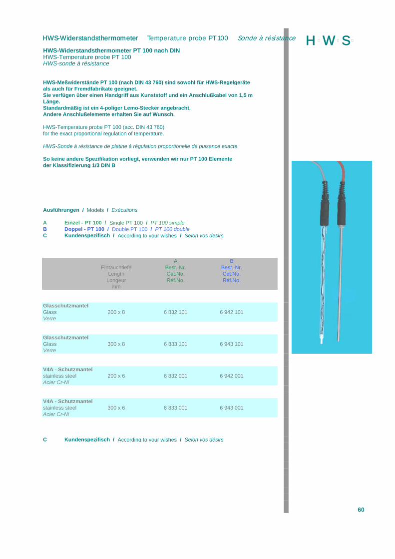
HWS-Widerstandsthermometer PT 100 nach DINHWS-Temperature probe PT 100HWS-sonde à résistance
HWS-Meßwiderstände PT 100 (nach DIN 43 760) sind sowohl für HWS-Regelgeräteals auch für Fremdfabrikate geeignet.Sie verfügen über einen Handgriff aus Kunststoff und ein Anschlußkabel von 1,5 mLänge. Standardmäßig ist ein 4-poliger Lemo-Stecker angebracht.Andere Anschlußelemente erhalten Sie auf Wunsch.
HWS-Temperature probe PT 100 (acc. DIN 43 760)for the exact proportional regulation of temperature.
HWS-Sonde à résistance de platine à régulation proportionelle de puisance exacte.
So keine andere Spezifikation vorliegt, verwenden wir nur PT 100 Elementeder Klassifizierung 1/3 DIN B
Ausführungen / Models / Exécutions
A Einzel - PT 100 / Single PT 100 / PT 100 simpleB Doppel - PT 100 / Double PT 100 / PT 100 doubleC Kundenspezifisch / According to your wishes / Selon vos desirs
A BEintauchtiefe Best.-Nr. Best.-Nr.
Length Cat.No. Cat.No.Longeur Réf.No. Réf.No.
mm
GlasschutzmantelGlass 200 x 8 6 832 101 6 942 101Verre
GlasschutzmantelGlass 300 x 8 6 833 101 6 943 101Verre
V4A - Schutzmantelstainless steel 200 x 6 6 832 001 6 942 001Acier Cr-Ni
V4A - Schutzmantelstainless steel 300 x 6 6 833 001 6 943 001Acier Cr-Ni
C Kundenspezifisch / According to your wishes / Selon vos désirs
60
H þW þS þHWS-Widerstandsthermometer Temperature probe PT 100 Sonde à résistance
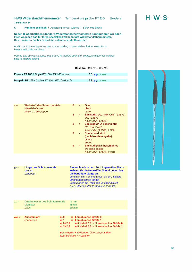
C Kundenspezifisch / According to your wishes / Selon vos désirs
Neben 8 lagerhaltigen Standard-Widerstandsthermometern konfigurieren wir nachIhren Angaben das für Ihren speziellen Fall benötigte Widerstandsthermometer.Bitte ergänzen Sie bei Bedarf die entsprechende Kennziffer.
Additional to these types we produce according to your wishes further executions.Please add code numbers.
Pour le cas où vous n'auriez pas trouvé le modèle souhaité, veuillez indiquer les chiffrespour le modèle désiré.
Best.-Nr. / Cat.No. / Réf.No.
Einzel - PT 100 / Single PT 100 / PT 100 simple 6 8xy yzz / ww
Doppel - PT 100 / Double PT 100 / PT 100 double 6 9xy yzz / ww
x = Werkstoff des Schutzmantels 0 = GlasMaterial of cover glassMatière d'enveloppe verre
1 = Edelstahl, s/s, Acier CrNi (1.4571)s/s, (1.4571)Acier CrNi (1.4571)
2 = Edelstahl/PFA beschichtets/s PFA coatedAcier CrNi (1.4571) / PFA
3 = Sonderwerkstoff(nach Kundenangabe)othersautres
4 = Edelstahl/Glas beschichtets/s glass-coatedAcier CrNi (1.4571) / verre
yy = Länge des Schutzmantels Eintauchtiefe in cm. Für Längen über 99 cmLength wählen Sie die Kennziffer 00 und geben SieLongueur die benötigte Länge an.
Length in cm. For length over 99 cm, indicate00 and add correct lengthLongueur en cm. Plus que 99 cm indiquezs.v.p. 00 et ajoutez le longueur correcte.
zz = Durchmesser des Schutzmantels in mmDiameter in mmDiam. en mm
ww = Anschlußart 4L0 = Lemobuchse Größe 0connection 4L1 = Lemobuchse Größe 1
4L0K2,5 mit Kabel 2,5 m / Lemostecker Größe 04L1K2,5 mit Kabel 2,5 m / Lemostecker Größe 1
Bei anderen Kabellängen bitte Länge ändern(z.B. bei 5 mtr = 4L0K5,0)
61
H þW þS þHWS-Widerstandsthermometer Temperature probe PT 100 Sonde àrésistance

Umwälzthermostate bis max. 200 °CBath circulators up to 200 °CThermostat à immersion jusqu à 200 °C
Umwälzthermostat mit LED-Displaymit Übertemperaturschutz, mit eingebauten KühlschlangeTyp A mit Schnittstelle RS 232
Technische Daten Typ A Typ BTechnical data Type A Type BCaractéristques Type A Type B
Abmessungen H x B x TSize mm 210 x 420 x 370 495 x 400 x 380Ouverture
GewichtWeight kg 9 11Poids
BetriebstemperaturbereichWorking range °C +40...+200 +40...+250Température
mit Wasserkühlungwith watercooling °C +20...+200 _+20...+250avec refroidissement par eau
TemperaturkonstanzAccuracy K ±0,02 ±0,02Précision
AnzeigeauflösungResolution K 0,1 0,1Resolution
HeizleistungPower Output W 2000 2000Puissance
UmwälzdruckpumpePressure pump L/min 15 20Pompe refoulante mbar 340 300
UmwälzsaugpumpeSuction pump L/min - 15Pompe aspirante mbar - 210
FüllvolumenVolume L 3...4,5 3...4,5Volume
AnschlußmöglichkeitElectrical Connections 1** 1*Connexion
Sicherheitsklasse DIN 12879Safety class DIN 12879 2 2
Best.Nr.Cat.No. 6 560 010 6 560 020 Abbildung und BeschreibungRéf.No. sind Herstellerangaben.
Änderungen bleiben vorbe-* PT 100 Externfühler 4-Leitertechnik, Programmgeber, Temperaturregler, halten
Multifunktionsbuchse PT 100 extern, 4 wire technique, commander, multifunctional socketPT 100 externe, commandeur, 4 ligne
** PT 100 Externfühler, RS 232CPT 100 extern, RS 232CPT 100 externe, RS 232C 62
H þW þS þUmwälzthermostat Bath Circulator Thermostat à immersion
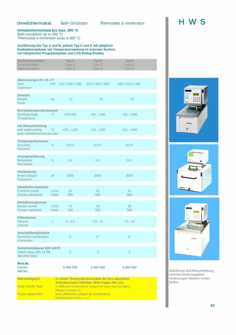
Umwälzthermostate bis max. 300 °CBath circulators up to 300 °CThermostat à immersion jusqu à 300 °C
Ausführung wie Typ A und B, jedoch Typ C und E mit adaptiverKaskadenregelung, mit Temperaturregelung im externen System,mit integriertem Programmgeber und LCD-Dialog-Display
Technische Daten Typ C Typ D Typ ETechnical data Type C Type D Type ECaractéristques Type C Type D Type E
Abmessungen H x B x TSize mm 210 x 390 x 380 320 x 460 x 380 300 x 420 x 480 Ouverture
GewichtWeight kg 12 18 18Poids
BetriebstemperaturbereichWorking range °C +45+250 +40...+300 +50...+300Température
mit Wasserkühlungwith watercooling °C +20...+250 +20...+300 +20...+300avec refroidissement par eau
TemperaturkonstanzAccuracy K ±0,01 ±0,01 ±0,01Précision
AnzeigeauflösungResolution K 0,1 0,1 0,1Resolution
HeizleistungPower Output W 2000 3000 3000Puissance
UmwälzdruckpumpePressure pump L/min 20 31 24Pompe refoulante mbar 290 540 500
UmwälzsaugpumpeSuction pump L/min 14 24 36Pompe aspirante mbar 180 420 360
FüllvolumenVolume L 3...4,5 7,5...12 7,5...12Volume
AnschlußmöglichkeitElectrical Connections 1* 1** 1*Connexion
Sicherheitsklasse DIN 12879Safety class DIN 12789 2 2 2Securité class.
Best.Nr.Cat.No. 6 560 030 6 560 040 6 560 050Réf.No. Abbildung und Beschreibung
sind Herstellerangaben.Wärmeträgeröl in vielen Temperaturbereichen für Ihre speziellen Änderungen bleiben vorbe-
Anforderungen lieferbar. Bitte fragen Sie uns. haltenHeat transfer fluid in different temperature ranges for your special tasks.
Please contact us.Fluide caloporteur pour differentes plages de température.
Questionnez nous s.v.p.
63
H þW þS þUmwälzthermostat Bath Circulator Thermostat à immersion

kompakte Bauweise, mit mechanischem 2-Stufen-Drehzahlbereich,umschaltbar, mit Überlastanzeige (Typ A und B)Agitator motors, robust, with speed controller and overload indicatorAgitateur moteur, robuste, avec réglage de vitesse et indicateur de sécurité
Elektronik-Laborrührwerke,für erhöhten Drehmomentbedarf (Typ C und D)Agitator motors with increased torque,Typ C and D with indicator of torque and overloadAgitateur moteur, avec un couple élevé,Mod: C et D avec indivateur de couple et sécurité indicateur
Technische Daten Typ A Typ B Typ C Typ DTechnical data Type A Type B Type C Type DCaractéristiques Type A Type B Type C Type D
Außenmaße (B x H x T)Dimensions mm 88x292x188 88x292x210 80x175x190 80x205x190Dimensions
GewichtWeight kg 2,9 3,1 2,8 2,8Poids
AnschlußleistungPower input W 70 70 75 75Puissance absorbée
AbgabeleistungPower output W 30 30 35 35Puissance débitée
DrehzahlbereichSpeed range(rpm) min-1 60...250 60...250 40...1200 50...2000Plage de vitesse 240...2000 240...2000
DrehzahlanzeigeSpeed indicator Skala LCD/Digital Skala LCD/DigitalAffichage de la vitesse
Best.-Nr.Cat. No. 6 550 010 6 550 020 6 550 021 6 550 022Réf.No.
Abbildung und Beschreibungsind Herstellerangaben.Änderungen bleiben vorbe-halten
64
H þW þS þUmwälzthermostat Bath Circulator Thermostat à immersion

Elektronik-Laborrührwerke für erhöhten DrehmomentbedarfTYP J mit elektronisch schaltbarem 2-Stufen-Getriebe, mit Überlastanzeigemit analoger bzw. analoger/digitaler SchnittstelleTyp F mit DrehmomenttrendanzeigeTyp I und J mit Drehzahl- und Drehmoment-AnzeigeElectronic stirrer motor for higher torqueType J with 2 step - gear, overload indicator with analog or analog/digital interfaceType E + F with torque trend indicatorType G + J with speed and torque displayMoteur agitateur pour intense moment de coupletype J avec réglage de vitesse, inidcateur de séceurité, avec analog ou analg/digital interfacetype E + F avec trend indicateur de coupletype G + J avec indicateur de vitesse et moment de couple
Typ E Typ F Typ G Typ JType E Type F Type G Type JType E Type F Type G Type J
80x205x190 80x205x190 72x206x176 82x211x176
3,5 3,8 2,8 3,7
130 130 70 140
110 110 50 100
8...40050...2000 50...2000 40...2000 40...2000
Skala LCD/Digital LCD/Digital LCD/Digital
6 550 023 6 550 024 6 550 025 6 550 050
65
H þW þS þHWS-Labor-Rührwerke Agitator Motors Agitateur moteurs
66
H þW þS þBorosilicatglas 3.3 (DIN-ISO 3585) entspricht den wichtigsten internationalen Normen, z.B.der englischen, amerikanischen und französischen. Höchstmögliche chemische Resistenz,minimale Wärmedehnung sowie die hierdurch bedingte hohe Tempera-turwechselbeständigkeit gehören zu den kennzeichnenden Eigenschaften. Dieses optimalephysikalische und chemische Verhalten prädestiniert dieses Glas für den Einsatz imLaborbereich sowie für großtechnische Anlagen im chemischen Apparatebau. Darüberhinaus gilt es als technisches Universalglas in allen weiteren Anwendungsbereichen, indenen extreme Hitzebeständigkeit, Temperaturwechselbeständigkeit, mechanische Festig-keit sowie außergewöhnliche chemische Resistenz gefordert wird.
Physikalische Eigenschaften von Borosilicatglas 3.3 (Duran, Pyrex):
Linearer Ausdehnungskoeffizient (20 - 300°C): 3,3 x 10⁻⁶/KKurzzeitige höchstzulässige Gebrauchstemperatur: 500 °CTransformationstemperatur (DIN 52324): 530 °C
Viskositätstemperatur:1014,5 dPas 510°C (untere Kühltemperatur)1013,0 dPas 560°C (obere Kühltemperatur)107,6 dPas 815°C (Erweichungstemperatur)104,0 dPas 1265°C (Verarbeitungstemperatur)
Dichte: 2,23 g/cm³
Unterhalb 510 °C (1014,5 dPas, untere Kühltemperatur) kann eine schnelle Abkühlung erfolgen,ohne dass bedeutende permanente Spannungen neu einfrieren.
Zur Beseitigung permanenter Spannungen wird Borosilicatglas auf maximal 550 °C erwärmtund bei dieser Temperatur über 30 min. gehalten. Für die anschließende Kühlung werdenAbkühlgeschwindigkeiten gemäß folgender Tabelle empfohlen:
Temperatur 550°C – 480 °C 480°C – 400 °C 400°C – 20 °C Bereich
Glasdicke Abkühlungsgeschwindigkeit
3 mm 12,0° C/min 24,0° C/min bis 480 °C/min6 mm 3,0° C/min 6,0° C/min bis 120 °C/min
12 mm 0,8° C/min 1,6° C/min bis 32 °C/min
Chemische Eigenschaften:
Borosilicatglas 3.3 ist gegen Wasser, neutrale und saure Lösungen, starke Säuren und derenMischungen sowie gegen Chlor, Brom, Jod und organische Substanzen sehr beständig.Auch bei längeren Einwirkungszeiten und Temperaturen über 100 °C übertrifft es in seinerchemischen Widerstandsfähigkeit die meisten Metalle und andere Werkstoffe.
Durch Einwirkung von Wasser und Säuren werden nur geringe Mengen, vorwiegendeinwertige Ionen, aus dem Glas gelöst. Dabei bildet sich auf der Glasoberfläche eine sehrdünne, porenarme Kieselschicht, die den weiteren Angriff hemmt.
Lediglich Flusssäure, hocherhitzte Phosphorsäure und alkalische Lösungen greifen mitsteigender Konzentration und Temperatur zunehmend die Glasoberfläche an.
Die chemische Resistenz verschiedener Glastypen und ihre Einteilung in Resistenzklassenwird in Deutschland nach den Standardmethoden DIN 12 111, 12 116 und 52 322 ermittelt.Aufgrund dieser Prüfmethoden erfüllt Borosilicatglas 3.3 alle Bedingungen der
hydrolytischen Klasse 1Säureklasse 1Laugenklasse 2
Schmelzverbindungen:
Es kann spannungsfrei mit anderen Borosilicatgläsern des Types 3.3 (DIN-ISO 3585)verschmolzen werden. Es kann bei den für diese Glasgruppe üblichen Temperaturenverarbeitet und entspannt werden.
Optische Eigenschaften:
Spektralbereich in dem die Absorption von Borosilicatglas 3.3 vernachlässigbar gering ist:ca. 310 bis 2200 nm.
Absorption bei braun eingefärbtem Glas bis ca. 500 nm.
Laborgläser aus Borosilicatglas 3.3 zeigen im sichtbaren Spektralbereich keine wesentlicheAbsorption. Sie wirken somit klar und farblos. Größere Schichtdicken (axiale Durchsicht beiRohren) erscheinen grünlich.
Für Arbeiten mit lichtempfindlichen Substanzen können die Oberflächen mit Diffusionsfarbebraun eingefärbt werden. Dabei ergibt sich eine starke Absorption im kurzwelligen Bereich.
Die Absorptionskante eingefärbter Gläser befindet sich bei ca. 500 nm.
Wenn nichts anderes vermerkt ist, sind unsere Produkte aus Borosil icatglas 3.3 hergestellt.
(Duran is an registered trade mark of Schott, Mainz)
67
H þW þS þBorosilicate glass 3.3 (DIN ISO 3585) represents the major international standards such asthe English, American and French. Highest possilbe chemical resistance, minimum thermalexpansion as well as the thereby conditioned high thermal shock resistance are its essentialcharacteristics. This optimum physical and chemical behaviour predisposes this glass to theapplication in laboratories and for large industrial installation in chemical plant systems. It isconsidered moreover to be an allround industrial glass in all other fields of application wheremaximum thermal resistance, thermal shock resistance, mechanical resistance as well asunusual chemical resistance are required.
Physical properties of borosilicate glass 3.3 (Duran, Pyrex):
Linear coefficient of expansion (20 - 300°C): 3,3 x 10⁻⁶/KTemporary maximum allowable sercive temperature: 500°CTransformation temperature (DIN 52324): 530°C
Viscosity temperature:1014,5 dPas 510°C ( lower annealing temperature)1013,0 dPas 560°C (high annealing temperature)107,6 dPas 815°C (soft temperature)104,0 dPas 1265°C (working temperature)
Density: 2,23 g/cm³
Below 510°C (1014,5 dPas,, lower annealing temperature), borosilicate glass can bei annealedquickly, without major permanent stresses refreezing.
To eliminate permanent stresses, our borosilicate glass is heated up to a maximum of 550°Cand maintained at said temperature during 30 minutes. For subsequent annealing the ratesin the table below are recommended.
temperature 550°C - 480°C 480°C – 400°C 400°C – 20°Crange
Glass thickness Annealing rate
3 mm 12,0° C/min 24,0° C/min upto 480° C/min 6 mm 3,0° C/min 6,0° C/min upto 120° C/min12 mm 0,8° C/min 1,6° C/min upto 32° C/min
Chemical properties:
Borosilicate glass 3.3 is highly resistant to water, neutral and acid solutions, concentratedacids and their mixtures, as well as to chlorine, bromine and organic matters. Even duringextended periods of reaction and at temperatures above 100°C, its chemical resistanceexceeds that of most metals and other materials.
By the action of water and acids only small amounts of mainly monovalent ions areeliminated from the glass. On the glass surface, a very thin, almost non-porous silica gellayer then forms inhibiting any further materials.
Only hydrofluric acid, very hot phosphoric acid and alkaline solution increasingly attack theglass surface with rising concentration and temperature.
The chemical resistance of different glass types and their classification in stablility classesare deter-mined in Germany according to the standard methods DIN 12111, 12116 and52322. On the basis of these methods, borosilicate glass 3.3 meets all requirements of
hydrolytic class 1acid glass 1alkaline solution class 2
Sealing:
It can be sealed stress-free to borosilicate glasses of the type 3.3 (DIN ISO 3585). It can beworked and and annealed at the temperatures which are usual for this group of glasses.Sealing of borosilicate glass 3.3 to glasses of higher thermal expansion is possible with theapplication of appropriate intermendiate glasses.
Optical properties:
Spectral region where the absorption of borosilicate glass 3.3 is negligibly small: approx. 310to 2200nm.
Absorption with amber-tinted glass: up to approx. 500nm
Laboratory glassware from borosilicate glass 3.3 show no noticeable absorption in the visibleregion of the spectrum. It appears consequently clear and colourless. Larger thickness (axialtransparency of tubes) show a greenish tint.
For working with light-sensitive matters, surfaces may be tinted amber with diffusion paint.This causes heavy absorption in the short-wave range.
The absorption edge of tinted glasses is at approx. 500nm.
(Duran is an registered trade mark of Schott, Mainz)
68
H þW þS þLe verre borosilicaté 3.3 (DIN ISO 3585) est internationalement reconnu et est conforme aux normes anglaises, américanes et francaises. Il se distingue par une résistance chimique maximale, une dilatation thermique minimale et, par là-meme, par une résistance élevée aux chocs thermiques. Ce comporte-ment physique et chimique optimal prédesine le verre borosilicaté 3.3 à l’emploi dans le laboratoires ainisi que les installations industrielles dans le secteur de la construction d’apparails chimiques. En outre, le verre borosilicatè 3.3 constitue un verre industriel d’emploi universel dans tous les autres secteurs d’emploi qui exigent une stabilité extrême à l’action de la chaleur, une résistance aux chocs thermiques, une résistance mécanique élevée ainsi qu’une résistance exeptionelle aux agents chimiques.
Propriétés physiques de verre borosilicaté 3.3 (Duran, Pyrex):
Coefficient linéaire de dilatation (20/300°C): 3,3 x 10⁻⁶/KTempératur maximale admissible pouvant etreappliquée pendant un court laps des temps: 500°CTempérature de transformation (DIN 52324): 530°C
Température de viscosité:1014,5 dPas 510°C (température inférieure de refroidissement)1013,0 dPas 560°C (température supérieure de refroidissement)107,6 dPas 815°C (température de ramollissement)104,0 dPas 1265°C (température de mise en oeuvre)
Densité: 2,23 g/cm³
En dessous de 510°C (1014,5 dPas, température inférieure de refroidissement) on peut refroidir rapidement le verre borosilcaté 3.3 sans incorporation, par solidification, de nouvelles tensions permanentes notables.
Pour éliminer les tensions permanentes, on porte le verre borosilicatè 3.3 à une température maximale de 550°C et on le maintient à cette température pour un laps de temps de 30 minutes. Pour le refroidissiment, nous recommandons d’appliquer les vitesses de refroidissement indiquées sur le tableau suivant:
plage de 550°C - 480°C 480°C – 400°C 400°C – 20°C température
Épaisseur du verre Vitesse de refroidissement
3 mm 12,0° C/min 24,0° C/min jusqu’à 480°C/min6 mm 3,0° C/min 6,0° C/min jusqu’à 120° C/min12 mm 0,8° C/min 1,6° C/min jusqu’à 32° C/min
Propriétés chimiques:
Le verre borosilicaté 3.3 présente une résistance très élevée à l’eau , aux solutations neutres etacides, aux acides forts et à leurs mélanges ainsi qu’au chlore, au brome, à l’iode et aux substances organiques.Meme dans le cas d’exposition à de telles sollicitations pendant substances une durée assez lonque et à des températures supérieurs à 100°C, sa résistance chimique est supérieure à celle de la plupart des métaux et d’autres matérieux.
L’action de l’eau et des acides n’a pour effet d’éliminier de verre que de faibles quantités qui sont con- stituées essentiellement par des ions monovalents. Il se forme en l’occurrence sur la surface du verre un chouche très mince de gel de silice pouvre en pores qui empeche la poursuite de l’attaque par ces agents.
Seuls l’acide flourhydrique, l’acide phosphorique tr’es chaud et les solutions alcalines attaquent de facon croissante la surface de verre au fur et à mesure que leur concentration et la températurre s’accroissent.
En Allemagne, la résistence chimique de différents types de verre et leur subdivision en classes de rési-stance sont déterminées selon le méthodes standardisées DIN 12111, 1211116 et 53322. Sur la base de ces méthodes d’essais, le verre borosilicaté 3.3 satisfait à toutes conditions des classes:
classes hydrolytiqes 1classe acides 1classe alcalins 2
Assemblages par fusion:
Il peut etre assemblé par fusion sans tension avec des verres borosilicatés de type 3.3(DIN ISO 3585). Il peut etre mis en oeuvre et détendu aus températures usuelles pour cette catégorie deverre. Il est possible d’assembler par fusion le verre borosilicaté 3.3 à des verres qui ont une dilatation thermique plus èlevée en recourant à l’emploi de raccords de verre appropriés.
Propriétés optiques:Plage spectrale dans laquelle l’absorption de verre borosilicatè 3.3 est négligeable: environ 310 à 2220 nm.
Absorption pour le verre teint en brun: jusqu’à environ 500 nm.
La verrerie en verre borosilicaté 3.3 ne présente pas d’absorption notable dans la plage pectrale visible. Il apparit en conséquence clir et incolore. Les épaisseurs de couche plus importantes (transparence axiable de tubes) apparaissent verdates.
Pour le travaux avec de substances sensibles à la lumiére, on peut teindre en brun avec un cécement le surfaces du vere. On obient ainsi une forte adsorption dans la plage à ondes courtes.
La limite d’adsorption des verres teints se situe aux alentours de 500 nm.
(Duran est une marque déposée de Schott, Mainz)
69
H þW þS þINDEX
An- / Aufbauteile.............................................................................. 54
Bodenauslaufhahn.......................................................................... 12
Bodenablaufventil, manuell........................................................... 10
Bodenablaufventil, mit integriertem PT 100................................. 10
Bodenablaufventil, pneumatisch.................................................. 14
Dichtung.......................................................................................... 19
Dimrothkühler................................................................................. 51
Doppelkupplung............................................................................. 47
Dosiertrichter, manuell.................................................................. 52
Dosiertrichter, pneumatisch.......................................................... 53
Ersatzteile für
- Bodenablaufventil......................................................................... 12
- Rührverschluß............................................................................... 35
- Tragegestell................................................................................... 31ff
- Thermometerverschluß................................................................ 33
Gabelklemmen für Kugelschliffe.................................................. 44
Gabelklemmen für Normschliffe................................................... 44
Gleitring-Rührverschluß................................................................ 37
Heizhauben..................................................................................... 28
HWS-Klemme.................................................................................. 44
Kontaktthermometer...................................................................... 59
Laborregler LR 03........................................................................... 56
Laborregler LR 20........................................................................... 56
Metalladapter für Metallschlauchanschluß.................................. 47ff
Metallschlauch, thermisch isoliert................................................ 47
Normschliffklemme, HWS.............................................................. 44
Planschliffdeckel............................................................................. 15ff
Planschliffgefäße............................................................................. 1ff
- zylindrisch...................................................................................... 1
- kurze Bauform................................................................................ 1
- zylindrisch, mit Bodenablauf........................................................ 2
- kurze Bauform, mit Bodenablauf.................................................. 2
- zylindrisch, mit Bodenablaufventil............................................... 3
- kurze Bauform, mit Bodenablaufventil......................................... 3
Planschliffgefäße mit Heiz-/Kühlmantel.......................................... 4ff
- zylindrisch........................................................................................ 4
- kurze Bauform.................................................................................. 4
- zylindrisch, mit Bodenablauf.......................................................... 5
- kurze Bauform, mit Bodenauslauf................................................. 5
- zylindrisch, mit Bodenablaufventil................................................ 6
- kurze Bauform, mit Bodenablaufventil.......................................... 6
- zylindrisch, mit Vakuummantel und Bodenablaufventil.............. 7
- zylindrisch,, mit beheiztem Bodenablaufventil............................. 7
- zylindrisch, mit exzentrischem beheiztem Bodenablaufventil
und Rührerlager.................................................................................. 8
70
H þW þS þ- zylindrisch, mit Ringbrause und Bodenauslaufventil................. 8
- kurze Bauform, mit Ringbrause und Bodenauslaufventil.......... 8
Pneumatik-Steuereinheit PAV 90................................................... 13
Rührer............................................................................................... 38ff
- Ankerrührer.................................................................................... 40
- Begasungsrührer für Magnetrührkupplung............................... 36
- Einblattrührer................................................................................ 38
- Flügelrührer................................................................................... 39
- Rührer nach Hoesch..................................................................... 39
- Propellerrührer.............................................................................. 40
Rührerkupplung............................................................................... 42
Rührwellen........................................................................................ 38
Rührwellenschutz............................................................................. 43
Rührverschluß, mit doppelter Lippendichtung............................. 35
Rührverschluß, selbstnachstellend................................................ 34
Rührwerke, mechanisch, elektrisch................................................ 64ff
Schellenringverbinder...................................................................... 27
Schlauch (Silikon, Viton).................................................................. 46
Schlauchkupplung, HWS.................................................................. 45
Schnellverschluß für Planschliffgefäße.......................................... 24
Schraubschlauchkupplung.............................................................. 46
Temperaturregler LR 04.................................................................... 57
Temperaturregler LR 40.................................................................... 58
Thermometerverschluß..................................................................... 33
Tischtragegestell............................................................................... 32
Tragegestell........................................................................................ 30
Tragegabel.......................................................................................... 27
Tragering............................................................................................. 27
Tropftrichter........................................................................................ 49
Umwälzthermostat.............................................................................. 62ff
Verbinder für Planschliffe, Stativausführung................................... 22
Verbinder für Planschliffe, EInhägeausführung............................... 36
Wellenbrecherkorb.............................................................................. 29
Widerstandsthermometer PT 100...................................................... 60
Zweifachhalterung „Variogrip“ für Planschliffe............................... 25
Vakuum-Magnet-Rührverschlußkupplung....................................... 47
71
H þW þS þINDEX
Accessory parts............................................................................. 54ff
Adapter, metal, for flexible metallic hose....................................... 47
Agitator motor................................................................................ 64ff
Automatic controller LR 03............................................................. 56
Baffle.............................................................................................. 29
Bath circulators............................................................................... 62ff
Clamp connection........................................................................... 26
Clips for conical joints..................................................................... 44
Contact controller LR 20................................................................. 56
Contact thermometer...................................................................... 59
Couplings for stirrers....................................................................... 42
Dimroth condenser.......................................................................... 51
Dosing funnel, manually operated................................................... 52
- pneumatic...................................................................................... 53
Double coupling.............................................................................. 47
Dropping funnel............................................................................... 49
Flat flange lids................................................................................. 15ff
- discs.............................................................................................. 15
- jacketed......................................................................................... 18
- evacuated...................................................................................... 18
Flat flange vessels........................................................................... 1ff
- cylindrical....................................................................................... 1
- short form....................................................................................... 1
- cylindrical, with bottom outlet.......................................................... 2
- short form, with bottom outlet......................................................... 2
- cylindrical, with bottom outlet valve................................................ 3
- short form, with bottom outlet valve............................................... 3
Flat flange vessels, jacketed............................................................ 4ff
- cylindrical....................................................................................... 4
- short form....................................................................................... 4
- cylindrical, with bottom outlet......................................................... 5
- short form, with bottom outlet......................................................... 5
- cylindrical, with bottom outlet valve................................................ 6
- short form, with bottom outlet valve............................................... 6
- cylindrical, triple walled with bottom outlet valve............................ 7
- cylindrical, with heating bottom outlet............................................ 7
- cylindrical, with stirrer guide............................................................ 8
- cylindrical, with circular inlet............................................................ 8
- conical jacketed with valve.............................................................. 9
- conical triple with valve.................................................................... 9
Fork clamps for conical joints............................................................. 44
Fork clamps for sperical joints............................................................ 44
Heating mantles.................................................................................. 28
Heat exchanger in glass..................................................................... 50
Heat exchanger in stainless steel....................................................... 51
72
H þW þS þPinces à fourche pour joints spérique............................................ 44
Protection de tiges agitateurs......................................................... 43
Raccords à olives............................................................................ 45
Raccords à olives pour embout verre fileté..................................... 46
Raccord métal pour tuyeau métallique flexible................................ 47
Réacteurs à rodages plan............................................................... 1ff
- cylindrique..................................................................................... 1
- construction raccourcie................................................................. 1
- cylindrique avec écoulement......................................................... 2
- construction raccourcie avec écoulement..................................... 2
- cylindrique avec vanne d’écoulement........................................... 3
- construction raccourcie avec vanne d’écoulement....................... 3
- Réacteurs à rodages plans à double paroi................................... 4ff
- cylindrique..................................................................................... 4
- construction raccourcie................................................................. 4
- cylindrique avec écoulement.......................................................... 5
- construction raccourcie avec écoulement...................................... 5
- cylindrique avec vanne d’écoulement............................................ 6
- construction raccourcie avec vann d’écoulement........................... 6
- à trois parois................................................................................... 7
- à double paroi écoulement thermost............................................... 7
- guidage par le fond.......................................................................... 6
- chauf. circulaire................................................................................ 8
- conique, à double enveloppe........................................................... 9
Régulateur de contact LR 20.............................................................. 56
Régulateur de laboratoire LR 03......................................................... 56
Régulateur de temperature LR 04 A................................................... 57
Régulateur de temperature LR 40...................................................... 58
Robinet d’écoulement........................................................................ 12
Sonde à résistance PT 100............................................................... 60ff
Supports raccors moteurs agitateur.................................................. 42
- magnetique..................................................................................... 36
Thermomètres à contact de sécurite................................................. 59
Thermostat à immersion.................................................................... 62f
Tubes en silicone et viton.................................................................. 46
Tuyau métallique flexible................................................................... 47
Vanne d’écoulement, avec PT 100................................................... 10
Vanne d’écoulement, manuel........................................................... 10ff
Vanne d’écoulement, pneumatique.................................................. 13
73
H þW þS þINDEX
Accessories en verre...................................................................... 54ff
Accessoires pour:
- bouchons...................................................................................... 33
- bouchons d’agitation..................................................................... 32ff
- cadre porteur................................................................................ 32
- vanne d’écoulement...................................................................... 11
Agitateurs........................................................................................ 38ff
- à ailes............................................................................................ 39
- à ancres......................................................................................... 40
- à hélics.......................................................................................... 40
- à introduc. gaz en acier CrNi......................................................... 36
- à introduc. gaz en verre................................................................. 38
- à pale............................................................................................. 38
- selon Hoesch................................................................................. 39
- tige réctifiée................................................................................... 38
Agitateur moteur.............................................................................. 64ff
Anneau porteur................................................................................ 27
Bouchons......................................................................................... 33
Bouchons d’agitation, ajustage automatique................................... 34
Bouchons d’agitation, avec double jeux d’étanchéité...................... 35
Brise-lames...................................................................................... 29
Cadre porteur................................................................................... 30
Cadre porteur de table..................................................................... 32
Chauffages pour réacteurs.............................................................. 28
Clips HWS pour joints coniques...................................................... 44
Colliers de fixation............................................................................ 26
Couvercles de rodages plans........................................................... 15ff
- disque............................................................................................. 15
- à double enveloppe........................................................................ 18
- évacué........................................................................................... 18
Dimroth réfrigérants.......................................................................... 51
Dispositifs de fixation avec bras porteur........................................... 22
Dispositifs de fixation pour montage de cadre porteur..................... 23
Dispositif de serrage double „Variogrip“............................................ 25
Échangeur thermique........................................................................ 50
Entonnoirs à décanter, manuel.......................................................... 52
Entonnoirs à décanter, pneumatique................................................. 53
Entonnoirs clindrique......................................................................... 49
Fermeture rapide pour rodages plans................................................ 24
Fourche porteur.................................................................................. 27
Garniture étanche à anneau glissant................................................. 37
Joint d’agitateur KPG......................................................................... 37
Joint pour rodages plans.................................................................... 19ff
Pièces d’accouplement...................................................................... 45
Pinces à fourche pour joints coniques............................................... 44

74
H þW þS þPinces à fourche pour joints spérique............................................ 44
Protection de tiges agitateurs......................................................... 43
Raccords à olives............................................................................ 45
Raccords à olives pour embout verre fileté..................................... 46
Raccord métal pour tuyeau métallique flexible................................ 47
Réacteurs à rodages plan............................................................... 1ff
- cylindrique..................................................................................... 1
- construction raccourcie................................................................. 1
- cylindrique avec écoulement......................................................... 2
- construction raccourcie avec écoulement..................................... 2
- cylindrique avec vanne d’écoulement........................................... 3
- construction raccourcie avec vanne d’écoulement....................... 3
- Réacteurs à rodages plans à double paroi................................... 4ff
- cylindrique..................................................................................... 4
- construction raccourcie................................................................. 4
- cylindrique avec écoulement.......................................................... 5
- construction raccourcie avec écoulement...................................... 5
- cylindrique avec vanne d’écoulement............................................ 6
- construction raccourcie avec vann d’écoulement........................... 6
- à trois parois................................................................................... 7
- à double paroi écoulement thermost............................................... 7
- guidage par le fond.......................................................................... 6
- chauf. circulaire................................................................................ 8
- conique, à double enveloppe........................................................... 9
Régulateur de contact LR 20.............................................................. 56
Régulateur de laboratoire LR 03......................................................... 56
Régulateur de temperature LR 04 A................................................... 57
Régulateur de temperature LR 40...................................................... 58
Robinet d’écoulement........................................................................ 12
Sonde à résistance PT 100............................................................... 60ff
Supports raccors moteurs agitateur.................................................. 42
- magnetique..................................................................................... 36
Thermomètres à contact de sécurite................................................. 59
Thermostat à immersion.................................................................... 62f
Tubes en silicone et viton.................................................................. 46
Tuyau métallique flexible................................................................... 47
Vanne d’écoulement, avec PT 100................................................... 10
Vanne d’écoulement, manuel........................................................... 10ff
Vanne d’écoulement, pneumatique.................................................. 13
Das HWS-Lieferprogramm • range of products
Planschliffreaktionsgefäße und -zubehörKomplettanlagen • Einzelkomponenten • Sonderanfertigungflat flange reactor units and accessoriescomplete units • single components • laboratory equipment in glass
Allgemeine Glasbauteile • Laborgeräte aus Glasuniversal glass components for laboratories
Laborhilfen aus Metall und Kunststoff • Allgemeines Laborzubehörlaboratory aids in metal and plastic materials • general accessories for laboratories
Bauteile zur glastechnischen Weiterbearbeitung • Sonderanfertigung aus Glascomponents for glass blowers • components made to buyer's specification
Glasfiltergeräteglass filtration instruments
Laborelektronik • Laborregler • Temperaturregler • Steuergeräteelectronic equipment • laboratory regulators • temperature regulators •control instruments
Analyse- und Testgeräteanalytical and testing equipment
Biotechnologieanlagenbiotechnology plants
Kontaktthermometer • Widerstandsthermometer • Thermometer • Aräometercontact thermometers • platinum resistance thermometers
Sonderanfertigungen aus Metall und Kunststoffmetal and plastic accessories according to buyer's specification
Änderung vorbehalten • Changes are reserved • Sous réserve des modification
Qualitätsprodukte für Industrie und ForschungQuality products for Industry and research
H þW þS þ LabortechnikSaarstraße 52 Entwicklung und Fertigung
D 55 122 MainzLaborkomponenten
Postfach 3628 und -systeme aus Glas,D 55 026 Mainz Metall und Kunststoff
Telefon: (06131) 37456-0 Meß- und RegeltechnikTelefax: (06131) 30 49 827 Laborelektronik
e-mail: [email protected]