Handbuch Station Bearbeiten - robotics.ee.uwa.edu.au
104
Station Bearbeiten Handbuch Processing station Manual CD-ROM included 648813 DE/EN 04/06 R2.2
Transcript of Handbuch Station Bearbeiten - robotics.ee.uwa.edu.au
Station Bearbeiten Handbuch Processing station Manual
CD-ROM included
648813 DE/EN 04/06 R2.2
Bestimmungsgemäße Verwendung/Intended use
Diese Station ist ausschließlich für die Aus- und Weiterbildung im Bereich Automatisierung und Kommunikation entwickelt und hergestellt. Das Ausbildungsunternehmen und/oder die Ausbildenden hat/haben dafür Sorge zu tragen, dass die Auszubildenden die Sicherheitsvorkehrungen, die in den begleitenden Handbüchern beschrieben sind, beachten. Festo Didactic schließt hiermit jegliche Haftung für Schäden des Auszubildenden, des Ausbildungsunternehmens und/oder sonstiger Dritter aus, die bei Gebrauch/Einsatz der Anlage außerhalb einer reinen Ausbildungssituation auftreten; es sei denn Festo Didactic hat solche Schäden vorsätzlich oder grob fahrlässig verursacht.
This station has been developed and produced solely for vocational and further training purposes in the field of automation and communication. The company undertaking the training and/or the instructors is/are to ensure that trainees observe the safety precautions described in the manuals provided. Festo Didactic herewith excludes any liability for damage or injury caused to trainees, the training company and/or any third party, which may occur if the system is in use for purposes other than purely for training, unless the said damage/injury has been caused by Festo Didactic deliberately or through gross negligence.
Bestell.-Nr. / Order No. Benennung / Description: Bezeichnung / Designation: Stand / Status: Autoren / Authors: Grafik / Graphics: Layout / Layout:
648813 TECH.DOKUMENT. D:MP-TB-SB-DE/EN 04/2006 Frank Ebel, Markus Pany Doris Schwarzenberger, Albert Sigel 04/2006
© Festo Didactic GmbH & Co. KG, D-73770 Denkendorf, 2006 Internet: www.festo-didactic.com e-mail: [email protected]
Weitergabe sowie Vervielfältigung dieses Dokuments, Verwertung und Mitteilung seines Inhalts verboten, soweit nicht ausdrücklich gestattet. Zuwiderhandlungen verpflichten zu Schadenersatz. Alle Rechte vorbehalten, insbesondere das Recht, Patent-, Gebrauchsmuster- oder Geschmacksmusteranmeldungen durchzuführen.
The copying, distribution and utilisation of this document as well as the communication of its contents to others without express authorisation is prohibited. Offenders will be held liable for the payment of damages. All rights reserved, in particular the right to carry out patent, utility model or ornamental design registration.
2 © Festo Didactic GmbH & Co. KG • 648813
Inhalt/Contents
1. Einleitung ____________________________________________________ 7 1.1 Lerninhalte ____________________________________________________ 8 1.2 Wichtige Hinweise ______________________________________________ 9 1.3 Verpflichtung des Betreibers _____________________________________ 9 1.4 Verpflichtung der Auszubildenden _________________________________ 9 1.5 Gefahren im Umgang mit dem Modularen Produktions-System_________ 10 1.6 Gewährleistung und Haftung ____________________________________ 11 1.7 Bestimmungsgemäße Verwendung _______________________________ 11 2. Sicherheitshinweise ___________________________________________ 13 3. Technische Daten _____________________________________________ 15 3.1 Kombinationen________________________________________________ 15 4. Transport/Auspacken/Lieferumfang______________________________ 17 5. Aufbau und Funktion___________________________________________ 19 5.1 Die Station Bearbeiten _________________________________________ 19 5.2 Funktion _____________________________________________________ 21 5.3 Ablaufbeschreibung ___________________________________________ 21 5.4 Modul Rundschalttisch _________________________________________ 23 5.5 Modul Prüfen_________________________________________________ 24 5.6 Modul Bohren ________________________________________________ 25 6. Inbetriebnahme_______________________________________________ 27 6.1 Arbeitsplatz __________________________________________________ 27 6.2 Mechanischer Aufbau __________________________________________ 28 6.2.1 Montage von Profilplatte und Bedienpult __________________________ 28 6.2.2 Montage der Station ___________________________________________ 29 6.3 Sensoren justieren_____________________________________________ 30 6.3.1 Kapazitiver Näherungsschalter (Rundschalttisch, Werkstücknachweis) __ 30 6.3.2 Induktiver Näherungsschalter (Rundschalttisch, Positionierung) _______ 31 6.3.3 Induktiver Näherungsschalter (Prüfen, Werkstückorientierung) ________ 32 6.3.4 Microschalter (Bohren, Linearachse) ______________________________ 33 6.4 Sichtprüfung _________________________________________________ 34
© Festo Didactic GmbH & Co. KG • 648813 3

Inhalt/Contents
6.5 Kabelverbindungen ____________________________________________ 35 6.6 Spannungsversorgung _________________________________________ 36 6.7 SPS Programm laden___________________________________________ 36 6.7.1 Siemens Steuerungen __________________________________________ 36 6.7.2 Festo Steuerungen_____________________________________________ 39 6.7.3 Allen Bradley Steuerungen ______________________________________ 41 6.7.4 Mitsubishi/MELSEC Steuerungen_________________________________ 44 6.8 Ablauf starten ________________________________________________ 46 6.9 Kombination von Stationen______________________________________ 47 6.9.1 Vernetzung___________________________________________________ 47 7. Wartung _____________________________________________________ 49 Inhalt der CD-ROM ___________________________________________________ 51 Montageanleitungen ___________________________________________ 51 Schaltpläne __________________________________________________ 51 Programmierung ______________________________________________ 51 Stücklisten ___________________________________________________ 51 Videos_______________________________________________________ 51 Bedienungsanleitungen ________________________________________ 52 Datenblätter__________________________________________________ 52 Aktualisierungen ____________________________________________________ 53
4 © Festo Didactic GmbH & Co. KG • 648813
Inhalt/Contents
Contents 55 1. Introduction__________________________________________________ 57 1.1 Training contents ______________________________________________ 58 1.2 Important notes _______________________________________________ 59 1.3 Duty of the operating authority___________________________________ 59 1.4 Duty of trainees _______________________________________________ 59 1.5 Risks involved in dealing with the Modular Production System _________ 60 1.6 Warranty and liability __________________________________________ 61 1.7 Intended use _________________________________________________ 61 2. Notes on safety _______________________________________________ 63 3. Technical data ________________________________________________ 65 3.1 Combinations_________________________________________________ 65 4. Transport/Unpacking/Scope of delivery __________________________ 67 5. Design and function ___________________________________________ 69 5.1 The Processing station _________________________________________ 69 5.2 Function _____________________________________________________ 71 5.3 Sequence description __________________________________________ 71 5.4 Rotary indexing table module ____________________________________ 73 5.5 Testing module _______________________________________________ 74 5.6 Drilling module _______________________________________________ 75 6. Commissioning _______________________________________________ 77 6.1 Workstation __________________________________________________ 77 6.2 Mechanical set up _____________________________________________ 78 6.2.1 Assembling profile plate and control console _______________________ 78 6.2.2 Assembling the station _________________________________________ 79 6.3 Adjust sensors ________________________________________________ 80 6.3.1 Capacitive proximity sensor (Rotary indexing table, detection of workpiece) _____________________ 80 6.3.2 Inductive proximity sensor (Rotary indexing table, Positioning)_________ 81 6.3.3 Inductive proximity sensor (Testing, orientation of workpiece) _________ 82 6.3.4 Micro switch (Drilling, linear axis)_________________________________ 83 6.4 Visual check __________________________________________________ 84
© Festo Didactic GmbH & Co. KG • 648813 5
Inhalt/Contents
6.5 Cable connections _____________________________________________ 85 6.6 Voltage supply ________________________________________________ 86 6.7 Loading the PLC program _______________________________________ 86 6.71 Siemens controller_____________________________________________ 86 6.7.2 Festo controller _______________________________________________ 89 6.7.3 Allen Bradley controller _________________________________________ 91 6.7.4 Mitsubishi/MELSEC controller ___________________________________ 94 6.8 Starting the sequence __________________________________________ 96 6.9 Combination of stations ________________________________________ 97 6.9.1 Networking___________________________________________________ 97 7. Maintenance _________________________________________________ 99 Content of the CD-ROM ______________________________________________ 101 Assembly instructions _________________________________________ 101 Circuit diagrams______________________________________________ 101 Programming ________________________________________________ 101 Parts lists ___________________________________________________ 101 Videos______________________________________________________ 101 Operating instructions_________________________________________ 102 Data sheets _________________________________________________ 102 Updates _________________________________________________________ 103
6 © Festo Didactic GmbH & Co. KG • 648813
1. Einleitung
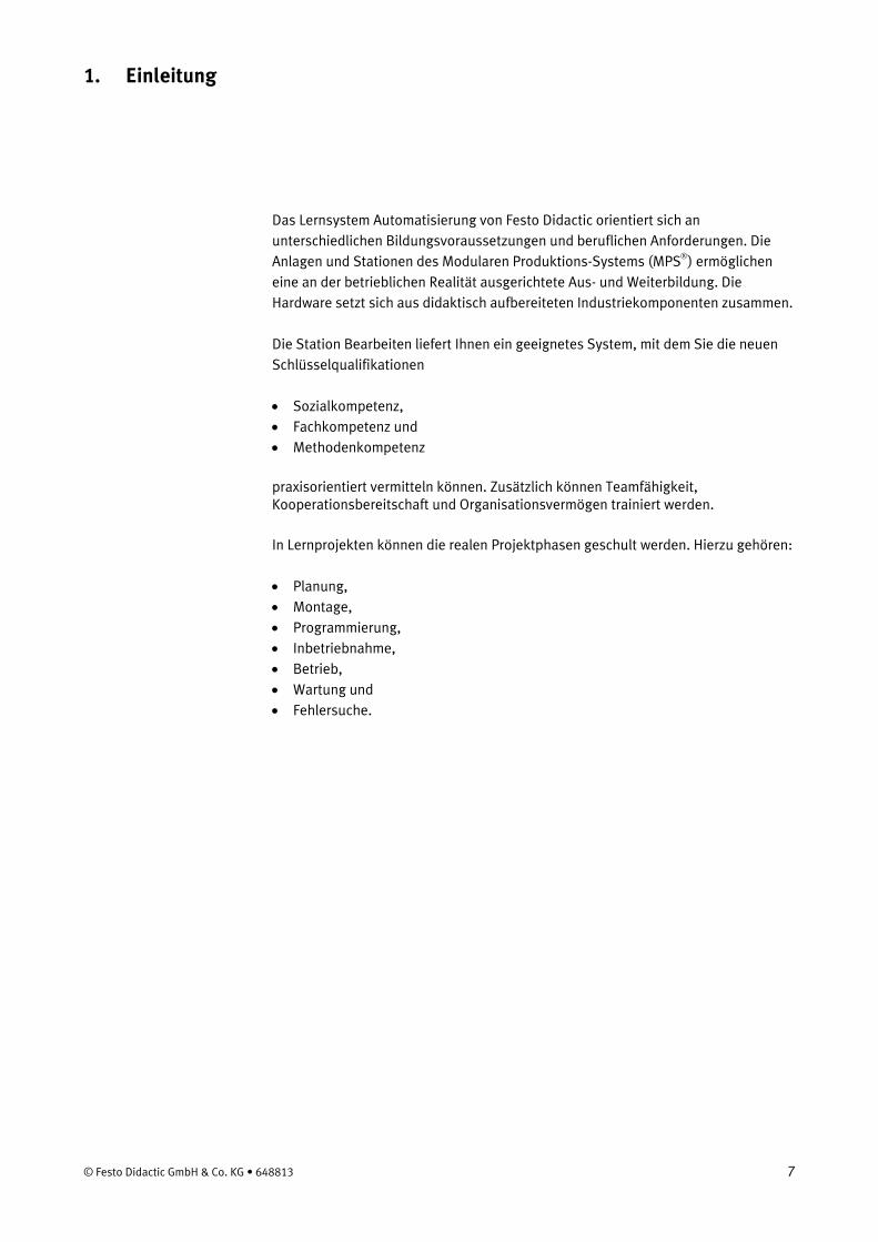
Das Lernsystem Automatisierung von Festo Didactic orientiert sich an unterschiedlichen Bildungsvoraussetzungen und beruflichen Anforderungen. Die Anlagen und Stationen des Modularen Produktions-Systems (MPS®) ermöglichen eine an der betrieblichen Realität ausgerichtete Aus- und Weiterbildung. Die Hardware setzt sich aus didaktisch aufbereiteten Industriekomponenten zusammen.
Die Station Bearbeiten liefert Ihnen ein geeignetes System, mit dem Sie die neuen Schlüsselqualifikationen
• Sozialkompetenz, • Fachkompetenz und • Methodenkompetenz
praxisorientiert vermitteln können. Zusätzlich können Teamfähigkeit, Kooperationsbereitschaft und Organisationsvermögen trainiert werden.
In Lernprojekten können die realen Projektphasen geschult werden. Hierzu gehören:
• Planung, • Montage, • Programmierung, • Inbetriebnahme, • Betrieb, • Wartung und • Fehlersuche.
© Festo Didactic GmbH & Co. KG • 648813 7
1. Einleitung
1.1 Lerninhalte
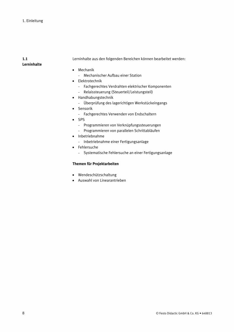
Lerninhalte aus den folgenden Bereichen können bearbeitet werden:
• Mechanik – Mechanischer Aufbau einer Station
• Elektrotechnik – Fachgerechtes Verdrahten elektrischer Komponenten – Relaissteuerung (Steuerteil/Leistungsteil)
• Handhabungstechnik – Überprüfung des lagerichtigen Werkstückeingangs
• Sensorik – Fachgerechtes Verwenden von Endschaltern
• SPS – Programmieren von Verknüpfungssteuerungen – Programmieren von parallelen Schrittabläufen
• Inbetriebnahme – Inbetriebnahme einer Fertigungsanlage
• Fehlersuche – Systematische Fehlersuche an einer Fertigungsanlage
Themen für Projektarbeiten
• Wendeschützschaltung • Auswahl von Linearantrieben
8 © Festo Didactic GmbH & Co. KG • 648813
1. Einleitung
1.2 Wichtige Hinweise
Grundvoraussetzung für den sicherheitsgerechten Umgang und den störungsfreien Betrieb des MPS® ist die Kenntnis der grundlegenden Sicherheitshinweise und der Sicherheitsvorschriften
Dieses Handbuch enthält die wichtigsten Hinweise, um das MPS® sicherheitsgerecht zu betreiben.
Insbesondere die Sicherheitshinweise sind von allen Personen zu beachten, die am MPS® arbeiten.
Darüber hinaus sind die für den Einsatzort geltenden Regeln und Vorschriften zur Unfallverhütung zu beachten.
Der Betreiber verpflichtet sich, nur Personen am MPS® arbeiten zu lassen, die: 1.3 Verpflichtung des Betreibers • mit den grundlegenden Vorschriften über Arbeitssicherheit und Unfallverhütung
vertraut und in die Handhabung des MPS® eingewiesen sind, • das Sicherheitskapitel und die Warnhinweise in diesem Handbuch gelesen und
verstanden haben.
Das sicherheitsbewusste Arbeiten des Personals soll in regelmäßigen Abständen überprüft werden.
Alle Personen, die mit Arbeiten am MPS® beauftragt sind, verpflichten sich, vor Arbeitsbeginn:
1.4 Verpflichtung der Auszubildenden
• das Sicherheitskapitel und die Warnhinweise in diesem Handbuch zu lesen, • die grundlegenden Vorschriften über Arbeitssicherheit und Unfallverhütung zu
beachten.
© Festo Didactic GmbH & Co. KG • 648813 9

1. Einleitung
Das MPS® ist nach dem Stand der Technik und den anerkannten sicherheitstechnischen Regeln gebaut. Dennoch können bei ihrer Verwendung Gefahren für Leib und Leben des Benutzers oder Dritter bzw. Beeinträchtigungen an der Maschine oder an anderen Sachwerten entstehen.
1.5 Gefahren im Umgang mit dem Modularen Produktions-System
Das MPS® ist nur zu benutzen:
• für die bestimmungsgemäße Verwendung und • in sicherheitstechnisch einwandfreiem Zustand.
Störungen, die die Sicherheit beeinträchtigen können, sind umgehend zu beseitigen!
10 © Festo Didactic GmbH & Co. KG • 648813
1. Einleitung
1.6 Gewährleistung und Haftung
Grundsätzlich gelten unsere „Allgemeinen Verkaufs- und Lieferbedingungen“. Diese stehen dem Betreiber spätestens seit Vertragsabschluss zur Verfügung. Gewährleistungs- und Haftungsansprüche bei Personen- und Sachschäden sind ausgeschlossen, wenn sie auf eine oder mehrere der folgenden Ursachen zurückzuführen sind:
• Nicht bestimmungsgemäße Verwendung des MPS® • Unsachgemäßes Montieren, in Betrieb nehmen, Bedienen und Warten des MPS® • Betreiben des MPS® bei defekten Sicherheitseinrichtungen oder nicht
ordnungsgemäß angebrachten oder nicht funktionsfähigen Sicherheits- und Schutzvorrichtungen
• Nichtbeachten der Hinweise im Handbuch bezüglich Transport, Lagerung, Montage, Inbetriebnahme, Betrieb, Wartung und Rüsten des MPS®
• Eigenmächtige bauliche Veränderungen am MPS® • Mangelhafte Überwachung von Anlagenteilen, die einem Verschleiß unterliegen • Unsachgemäß durchgeführte Reparaturen • Katastrophenfälle durch Fremdkörpereinwirkung und höhere Gewalt.
Festo Didactic schließt hiermit jegliche Haftung für Schäden des Auszubildenden, des Ausbildungsunternehmens und/oder sonstiger Dritter aus, die bei Gebrauch/Einsatz der Anlage außerhalb einer reinen Ausbildungssituation auftreten; es sei denn Festo Didactic hat solche Schäden vorsätzlich oder grob fahrlässig verursacht.
1.7 Bestimmungsgemäße Verwendung
Diese Station ist ausschließlich für die Aus- und Weiterbildung im Bereich Automatisierung und Technik entwickelt und hergestellt. Das Ausbildungsunternehmen und/oder die Ausbildenden hat/haben dafür Sorge zu tragen, dass die Auszubildenden die Sicherheitsvorkehrungen, die in den begleitenden Handbüchern beschrieben sind, beachten.
Zur bestimmungsgemäßen Verwendung gehört auch:
• das Beachten aller Hinweise aus dem Handbuch und • die Einhaltung der Inspektions- und Wartungsarbeiten.
© Festo Didactic GmbH & Co. KG • 648813 11

1. Einleitung
12 © Festo Didactic GmbH & Co. KG • 648813

2. Sicherheitshinweise
Allgemein • Die Auszubildenden dürfen nur unter Aufsicht einer Ausbilderin/eines Ausbilders
an der Station arbeiten. • Beachten Sie die Angaben der Datenblätter zu den einzelnen Elementen,
insbesondere auch alle Hinweise zur Sicherheit!
Elektrik • Herstellen bzw. abbauen von elektrischen Verbindungen nur in spannungslosem
Zustand! • Verwenden Sie nur Kleinspannungen, maximal 24 V DC.
Mechanik • Montieren Sie alle Elemente fest auf die Platte. • Greifen Sie nur bei Stillstand in die Station.
Bohrmaschine • Die Bohrmaschine ist funktionsfähig. Halten Sie Abstand von der drehenden
Bohrspindel! • Der Poliervorgang wird aus Sicherheitsgründen nur simuliert.
© Festo Didactic GmbH & Co. KG • 648813 13

2. Sicherheitshinweise
14 © Festo Didactic GmbH & Co. KG • 648813
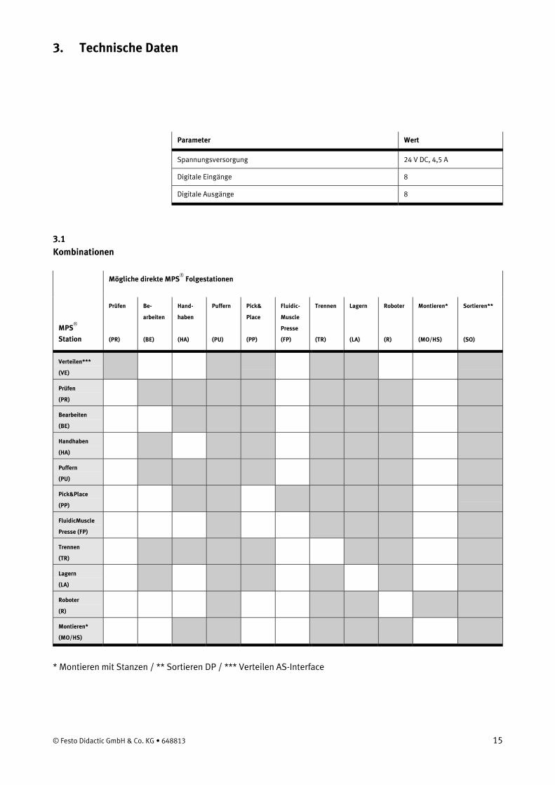
3. Technische Daten
Parameter Wert
Spannungsversorgung 24 V DC, 4,5 A
Digitale Eingänge 8
Digitale Ausgänge 8
3.1 Kombinationen
Mögliche direkte MPS®
Folgestationen
MPS®
Station
Prüfen
(PR)
Be-
arbeiten
(BE)
Hand-
haben
(HA)
Puffern
(PU)
Pick&
Place
(PP)
Fluidic-
Muscle
Presse
(FP)
Trennen
(TR)
Lagern
(LA)
Roboter
(R)
Montieren*
(MO/HS)
Sortieren**
(SO)
Verteilen***
(VE)
Prüfen
(PR)
Bearbeiten
(BE)
Handhaben
(HA)
Puffern
(PU)
Pick&Place
(PP)
FluidicMuscle
Presse (FP)
Trennen
(TR)
Lagern
(LA)
Roboter
(R)
Montieren*
(MO/HS)
* Montieren mit Stanzen / ** Sortieren DP / *** Verteilen AS-Interface
© Festo Didactic GmbH & Co. KG • 648813 15

3. Technische Daten
16 © Festo Didactic GmbH & Co. KG • 648813
4. Transport/Auspacken/Lieferumfang
Transport Das MPS® wird in einer Transportbox mit Palettenboden geliefert.
Die Transportbox darf ausschließlich mit geeigneten Hubwagen oder Gabelstaplern transportiert werden. Die Transportbox muss gegen Umfallen und Herunterfallen gesichert sein.
Transportschäden sind unverzüglich dem Spediteur und Festo Didactic zu melden.
Auspacken Beim Auspacken der Station das Füllmaterial der Transportbox vorsichtig entfernen. Beim Auspacken der Station darauf achten, dass keine Aufbauten der Station beschädigt werden.
Nach dem Auspacken die Station auf mögliche Beschädigungen überprüfen. Beschädigungen sind unverzüglich dem Spediteur und Festo Didactic zu melden.
Lieferumfang Den Lieferumfang entsprechend dem Lieferschein und der Bestellung überprüfen. Mögliche Abweichungen sind unverzüglich Festo Didactic zu melden.
© Festo Didactic GmbH & Co. KG • 648813 17

4. Transport/Auspacken/Lieferumfang
18 © Festo Didactic GmbH & Co. KG • 648813
5. Aufbau und Funktion
5.1 Die Station Bearbeiten
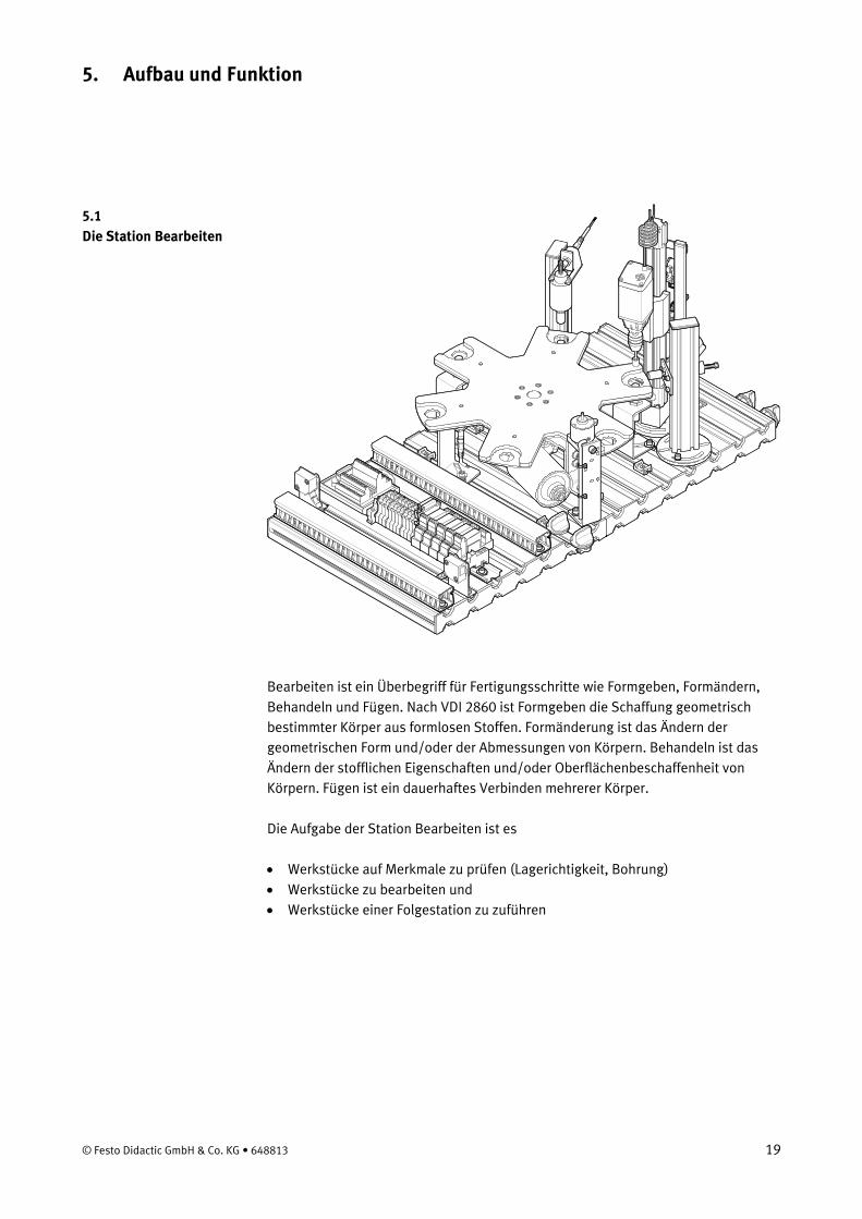
Bearbeiten ist ein Überbegriff für Fertigungsschritte wie Formgeben, Formändern, Behandeln und Fügen. Nach VDI 2860 ist Formgeben die Schaffung geometrisch bestimmter Körper aus formlosen Stoffen. Formänderung ist das Ändern der geometrischen Form und/oder der Abmessungen von Körpern. Behandeln ist das Ändern der stofflichen Eigenschaften und/oder Oberflächenbeschaffenheit von Körpern. Fügen ist ein dauerhaftes Verbinden mehrerer Körper.
Die Aufgabe der Station Bearbeiten ist es
• Werkstücke auf Merkmale zu prüfen (Lagerichtigkeit, Bohrung) • Werkstücke zu bearbeiten und • Werkstücke einer Folgestation zu zuführen
© Festo Didactic GmbH & Co. KG • 648813 19

5. Aufbau und Funktion
Der Aufbau der Station Bearbeiten besteht aus
• Modul Rundschalttisch • Modul Prüfen • Modul Bohren • Modul Spannen • Modul Weiche, elektrisch • Profilplatte
• Wagen • Bedienpult • SPS-Board
Station Bearbeiten mit Wagen, Bedienpult und SPS Board
20 © Festo Didactic GmbH & Co. KG • 648813

5. Aufbau und Funktion
5.2 Funktion
In der Station Bearbeiten werden Werkstücke auf einem Rundschalttisch geprüft und bearbeitet. Der Rundschalttisch wird von einem DC Motor angetrieben. Das Positionieren des Rundschalttisches wird mit einer Relaisschaltung realisiert, die Position des Rundschalttisches wird mit einem induktiven Sensor erfasst.
Am Rundschalttisch werden die Werkstücke in zwei parallelen Abläufen geprüft und gebohrt. Ein Hubmagnet mit induktivem Sensor überprüft, ob die Werkstücke lagerichtig eingelegt sind. Beim Bohren wird das Werkstück mit einem Hubmagnet gespannt.
Fertige Werkstücke werden mit einer elektrischen Weiche weitergeleitet.
Hinweis Die Station verwendet ausschließlich elektrische Aktoren.
Startvoraussetzung 5.3 Ablaufbeschreibung • Werkstück in Werkstückaufnahme Materialeingang
Ausgangsstellung • Rundschalttisch positioniert • Prüfspulenanker oben • Bohrmaschine oben • Motor Bohrmaschine ausgeschaltet • Spannvorrichtung eingefahren • Elektrische Weiche nicht betätigt
© Festo Didactic GmbH & Co. KG • 648813 21
5. Aufbau und Funktion
Ablauf
1. Wird ein Werkstück in der Werkstückaufnahme 1 erkannt und der START Taster gedrückt, wird der Rundschalttisch um 60° gedreht.
2. Der Prüfspulenanker fährt nach unten. Es wird geprüft, ob das Werkstück mit der Öffnung nach oben eingelegt ist. Ist das Ergebnis der Prüfung in Ordnung, wird der Rundschalttisch um 60° gedreht.
3. Die Spannvorrichtung spannt das Werkstück. Der Motor der Bohrmaschine wird eingeschaltet. Die Linearachse bewegt die Bohrmaschine nach unten.
4. Hat die Bohrmaschine ihre untere Position erreicht, wird die sie durch die Linearachse wieder an ihren oberen Anschlag bewegt.
5. Der Motor der Bohrmaschine wird ausgeschaltet, die Spannvorrichtung eingefahren. Der Rundschalttisch wird um 60° gedreht.
6. Die elektrische Weiche gibt das Werkstück an eine Folgestation weiter.
Dieser Ablauf beschreibt den Durchlauf eines Werkstückes durch die Station Bearbeiten. Das Werkstück befindet sich in der Übergabeposition an eine folgende Station. Nach Einlegen eines Werkstücks in Werkstückaufnahme 1 kann der Bearbeitungszyklus wieder gestartet werden.
22 © Festo Didactic GmbH & Co. KG • 648813
5. Aufbau und Funktion
5.4 Modul Rundschalttisch
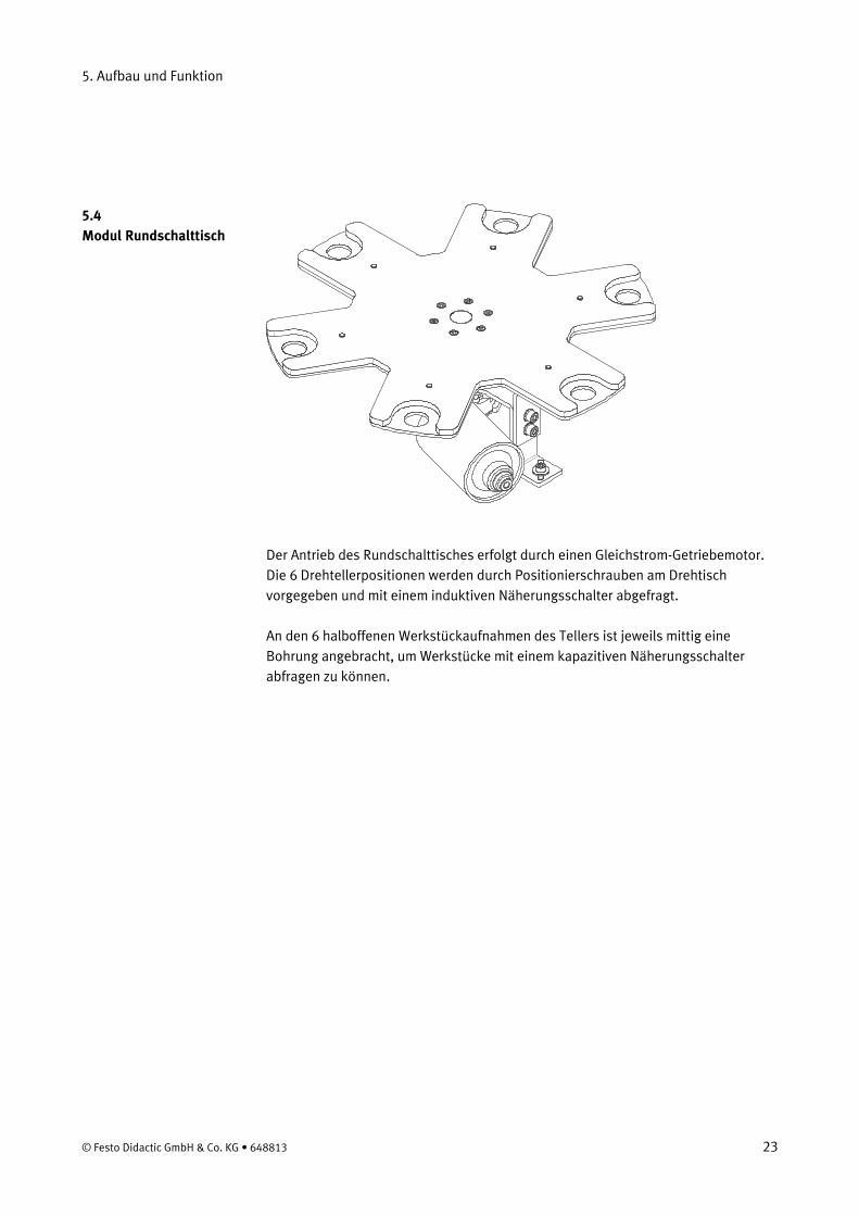
Der Antrieb des Rundschalttisches erfolgt durch einen Gleichstrom-Getriebemotor. Die 6 Drehtellerpositionen werden durch Positionierschrauben am Drehtisch vorgegeben und mit einem induktiven Näherungsschalter abgefragt.
An den 6 halboffenen Werkstückaufnahmen des Tellers ist jeweils mittig eine Bohrung angebracht, um Werkstücke mit einem kapazitiven Näherungsschalter abfragen zu können.
© Festo Didactic GmbH & Co. KG • 648813 23
5. Aufbau und Funktion
5.5 Modul Prüfen
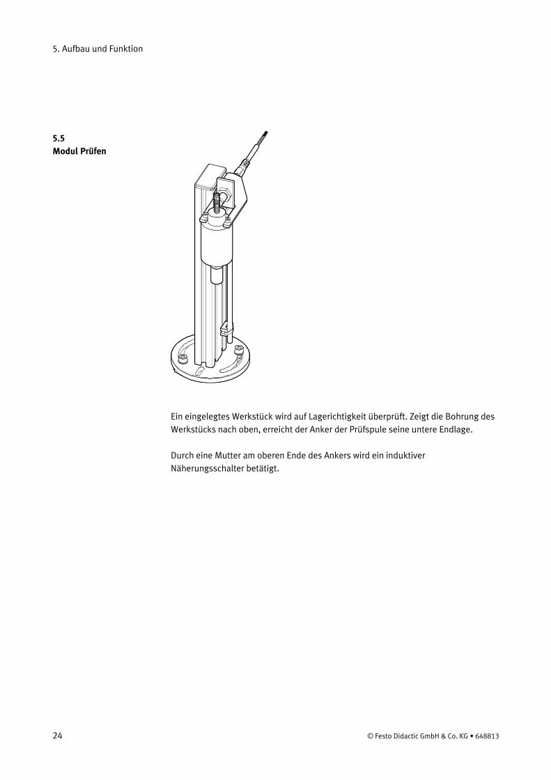
Ein eingelegtes Werkstück wird auf Lagerichtigkeit überprüft. Zeigt die Bohrung des Werkstücks nach oben, erreicht der Anker der Prüfspule seine untere Endlage.
Durch eine Mutter am oberen Ende des Ankers wird ein induktiver Näherungsschalter betätigt.
24 © Festo Didactic GmbH & Co. KG • 648813

5. Aufbau und Funktion
5.6 Modul Bohren
Mit dem Modul Bohren wird das Polieren einer Bohrung im Werkstück simuliert.
Eine elektrische Spannvorrichtung fixiert das Werkstück. Vorschub und Rückhub der Bohrmaschine erfolgen durch eine Linearachse mit Zahnriemen. Ein elektrischer Getriebemotor treibt die Linearachse an. Zur Ansteuerung des Motors wird eine Relaisschaltung verwendet.
Der Motor der Bohrmaschine wird mit 24 V DC betrieben und ist in der Drehzahl nicht regelbar.
Die Endlagenabfrage erfolgt durch elektrische Grenztaster. Anfahren der Grenztaster bewirkt eine Umkehr der Bewegungsrichtung der Linearachse.
© Festo Didactic GmbH & Co. KG • 648813 25

5. Aufbau und Funktion
26 © Festo Didactic GmbH & Co. KG • 648813
6. Inbetriebnahme
Die Stationen des MPS® werden generell
• komplett montiert • funktionsfähig als Einzelstation justiert • in Betrieb genommen • geprüft
geliefert.
Hinweis Bei einer Kombination von Stationen müssen eventuell Änderungen am mechanischen Aufbau und der Position und Einstellung von Sensoren vorgenommen werden.
Die Inbetriebnahme beschränkt sich normalerweise auf eine Sichtprüfung auf einwandfreie Verkabelung und das Anlegen der Betriebsspannung.
Alle Komponenten und Verkabelungen sind eindeutig gekennzeichnet, so dass ein Wiederherstellen aller Verbindungen problemlos möglich ist.
Zur Inbetriebnahme der MPS® Station benötigen Sie: 6.1 Arbeitsplatz
• die montierte und justierte MPS® Station • ein Bedienpult • ein SPS Board • ein Netzgerät 24 V DC, 4,5 A • einen PC mit installierter SPS Programmiersoftware
© Festo Didactic GmbH & Co. KG • 648813 27
6. Inbetriebnahme
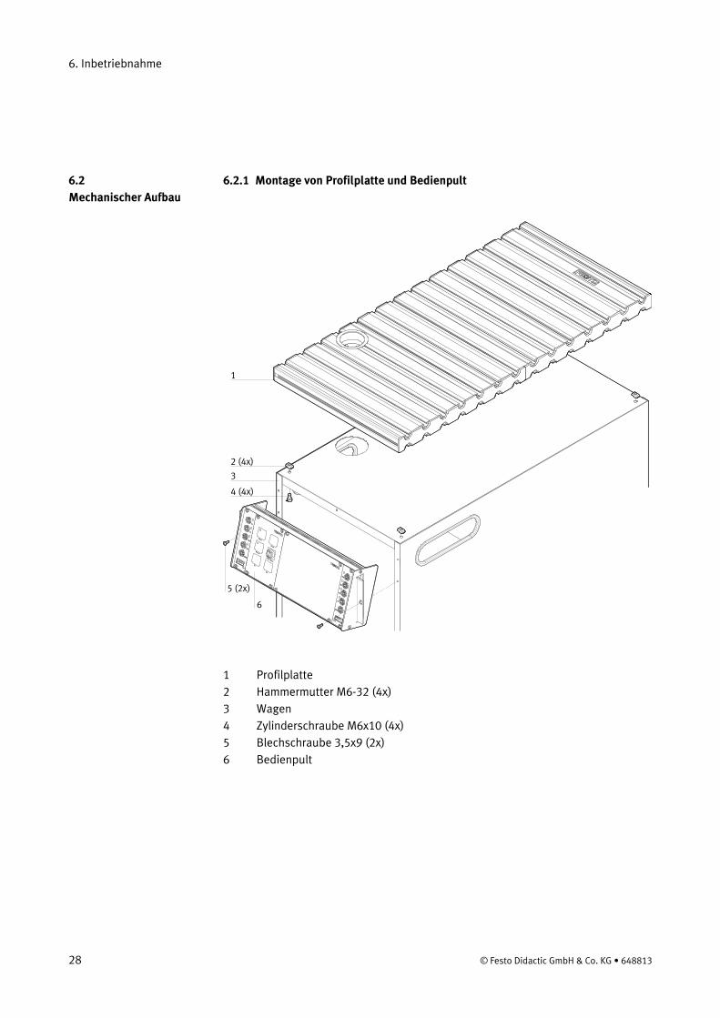
6.2.1 Montage von Profilplatte und Bedienpult 6.2 Mechanischer Aufbau
1
2 (4x)
4 (4x)
3
5 (2x)
6
1 Profilplatte 2 Hammermutter M6-32 (4x) 3 Wagen 4 Zylinderschraube M6x10 (4x) 5 Blechschraube 3,5x9 (2x) 6 Bedienpult
28 © Festo Didactic GmbH & Co. KG • 648813
6. Inbetriebnahme
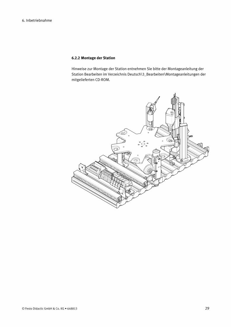
6.2.2 Montage der Station
Hinweise zur Montage der Station entnehmen Sie bitte der Montageanleitung der Station Bearbeiten im Verzeichnis Deutsch\3_Bearbeiten\Montageanleitungen der mitgelieferten CD-ROM.
© Festo Didactic GmbH & Co. KG • 648813 29

6. Inbetriebnahme
6.3.1 Kapazitiver Näherungsschalter (Rundschalttisch, Werkstücknachweis) 6.3 Sensoren justieren
Der kapazitive Näherungsschalter wird zum Werkstücknachweis eingesetzt. Das Werkstück verändert die Kapazität eines im Näherungsschalterkopf eingebauten Kondensators. Die Werkstücke werden unabhängig von Farbe und Material nachgewiesen.
Hinweis Die kapazitiven Näherungsschalter werden an den Positionen Materialeingang, Prüfen und Bohren verwendet.
Voraussetzungen – Das Modul Rundschalttisch ist montiert. – Elektrischer Anschluss der kapazitiven Näherungsschalter hergestellt – Netzgerät eingeschaltet.
Vorgehen 1. Legen Sie ein Werkstück in die Werkstückaufnahme. 2. Montieren Sie den Näherungsschalter mit dem Haltwinkel so, dass er den
Rundschalttisch nicht berührt und zentriert unter der Bohrung in der Werkstückaufnahme steht.
3. Stellen Sie den Abstand Näherungsschalter – Werkstück so ein, dass die Schaltzustandsanzeige (LED) einschaltet. Hinweis Der Näherungsschalter darf nicht durch den Drehteller des Rundschalttischs ausgelöst werden.
4. Kontrollieren Sie die Positionierung und Einstellung des Näherungsschalters durch wiederholtes Einlegen und Entnehmen von Werkstücken.
Dokumente • Datenblätter
Näherungsschalter, kapazitiv (178575) im Verzeichnis Deutsch\3_Bearbeiten\Datenblaetter der mitgelieferten CD-ROM.
• Montageanleitungen Station Bearbeiten im Verzeichnis Deutsch\3_Bearbeiten\Montageanleitungen der mitgelieferten CD-ROM.
30 © Festo Didactic GmbH & Co. KG • 648813

6. Inbetriebnahme
6.3.2 Induktiver Näherungsschalter (Rundschalttisch, Positionierung)
Der induktive Näherungsschalter wird zur Positionierung des Rundschalttisches eingesetzt. Induktive Näherungsschalter erkennen metallische Objekte. Der Schaltabstand variiert nach Metallart und Oberflächenbehandlung.
Voraussetzungen – Das Modul Rundschalttisch ist montiert. – Elektrischer Anschluss des induktiven Näherungsschalters hergestellt – Netzgerät eingeschaltet.
Vorgehen 1. Montieren Sie den Näherungsschalter mit dem Haltwinkel so, dass er zentriert
unter einer Positionierschraube des Rundschalttischs steht. Der Näherungsschalter hat einen Abstand von ca. 2 mm zur Positionierschraube.
2. Stellen Sie den Abstand Näherungsschalter – Positionierschraube so ein, dass die Schaltzustandsanzeige (LED) einschaltet.
3. Kontrollieren Sie die Positionierung und Einstellung des Näherungsschalters durch wiederholtes Drehen des Rundschalttisches.
Dokumente • Datenblätter
Näherungsschalter, induktiv (150395) im Verzeichnis Deutsch\3_Bearbeiten\Datenblaetter der mitgelieferten CD-ROM.
• Montageanleitungen Station Bearbeiten und Modul Rundschalttisch im Verzeichnis Deutsch\3_Bearbeiten\Montageanleitungen der mitgelieferten CD-ROM.
© Festo Didactic GmbH & Co. KG • 648813 31
6. Inbetriebnahme
6.3.3 Induktiver Näherungsschalter (Prüfen, Werkstückorientierung)
Der induktive Näherungsschalter wird zur Prüfung der Orientierung der Werkstücke eingesetzt. Induktive Näherungsschalter erkennen metallische Objekte. Der Schaltabstand variiert nach Metallart und Oberflächenbehandlung.
Voraussetzungen – Die Module Rundschalttisch und Prüfen sind montiert. – Elektrischer Anschlüsse des Moduls Prüfen und des Näherungsschalters
hergestellt. – Netzgerät eingeschaltet.
Vorgehen 1. Legen Sie ein Werkstück mit der Öffnung nach oben in die Werkstückaufnahme. 2. Schalten Sie die Versorgungsspannung der Spule des Moduls Prüfen ein. 3. Positionieren Sie den induktiven Näherungsschalter so, dass er einen Abstand
von ca. 1 mm zur Mutter am Taststift des Moduls Prüfen hat. 4. Stellen Sie den Abstand Näherungsschalter – Mutter so ein, dass die
Schaltzustandsanzeige (LED) einschaltet. 5. Kontrollieren Sie die Positionierung und Einstellung des Näherungsschalters
durch wiederholtes Einschalten und Ausschalten der Spule.
Dokumente • Datenblätter
Näherungsschalter, induktiv (150395) im Verzeichnis Deutsch\3_Bearbeiten\Datenblaetter der mitgelieferten CD-ROM.
• Montageanleitungen Station Bearbeiten im Verzeichnis Deutsch\3_Bearbeiten\Montageanleitungen der mitgelieferten CD-ROM.
32 © Festo Didactic GmbH & Co. KG • 648813
6. Inbetriebnahme
6.3.4 Microschalter (Bohren, Linearachse)
Die Microschalter werden zur Endlagenkontrolle der Linearachse eingesetzt. Die Microschalter werden durch den Schlitten der Linearachse betätigt.
Voraussetzungen – Das Modul Bohren ist montiert – Elektrischer Anschluss des Moduls Bohren hergestellt. – Elektrischer Anschluss der Microschalter hergestellt. – Netzgerät eingeschaltet.
Vorgehen 1. Fahren Sie die Bohrmaschine in die obere Endlage. 2. Verschieben Sie den Microschalter in der Halterung, bis er durchschaltet. 3. Ziehen Sie die Befestigungsschrauben an. 4. Fahren Sie die Bohrmaschine in die untere Endlage. 5. Verschieben Sie den Microschalter in der Halterung, bis er durchschaltet. 6. Ziehen Sie die Befestigungsschrauben an. 7. Kontrollieren Sie die Positionierung der Microschalters durch wiederholte
Probeläufe des Moduls Bohren (Bohrmaschine nach oben/Bohrmaschine nach unten fahren).
Dokumente • Datenblätter
Microschalter S-3-E (007347) im Verzeichnis Deutsch\3_Bearbeiten\Datenblaetter der mitgelieferten CD-ROM.
• Montageanleitungen Station Bearbeiten und Modul Bohren im Verzeichnis Deutsch\3_Bearbeiten\Montageanleitungen der mitgelieferten CD-ROM.
© Festo Didactic GmbH & Co. KG • 648813 33
6. Inbetriebnahme
6.4 Sichtprüfung
Die Sichtprüfung muss vor jeder Inbetriebnahme durchgeführt werden!
Überprüfen Sie vor dem Start der Station:
• die elektrischen Anschlüsse • die mechanischen Komponenten auf sichtbare Defekte
(Risse, lose Verbindungen usw.)
Beseitigen Sie entdeckte Schäden vor dem Start der Station!
34 © Festo Didactic GmbH & Co. KG • 648813

6. Inbetriebnahme
1
2
6.5 Kabelverbindungen
Kabelverbindungen zwischen SPS-Board, Bedienpult und Station
1. SPS Board – Station Stecken Sie den Stecker XMA2 des SPS Boards in die Buchse XMA2 des E/A-Terminals der Station.
2. SPS Board – Bedienpult Stecken Sie den Stecker XMG1 des SPS Boards in die Buchse XMG1 des Bedienpults.
3. SPS Board – Netzgerät Stecken Sie die 4 mm Sicherheitsstecker in die Buchsen des Netzgerätes.
4. PC – SPS Verbinden Sie Ihren PC durch ein Programmierkabel mit der SPS.
© Festo Didactic GmbH & Co. KG • 648813 35
6. Inbetriebnahme
• Die Stationen werden über ein Netzgerät mit 24 V Gleichspannung (max. 5 A) versorgt.
6.6 Spannungsversorgung
• Die Spannungsversorgung der kompletten Station erfolgt über das SPS Board.
6.7.1 Siemens Steuerungen 6.7 SPS Programm laden
• Steuerungen: Siemens S7-313C, S7-313C-2DP, S7-314 oder S7-315-2DP • Programmiersoftware: Siemens STEP7 Version 5.1 oder höher
1. PC und Steuerung mit dem RS232-Programmierkabel mit PC-Adapter verbinden 2. Netzgerät einschalten 3. Druckluftversorgung einschalten 4. NOT-AUS Taster entriegeln (falls vorhanden) 5. SPS Speicher urlöschen:
– Warten Sie, bis die SPS ihre Prüfroutinen beendet hat. CPU 31xC – Drücken Sie den Betriebsartenschalter nach MRES. Halten Sie den
Betriebsartenschalter in dieser Stellung, bis die STOP-LED zum 2. Mal aufleuchtet und dauerhaft leuchtet (entspricht 3 s). Lassen Sie dann den Betriebsartenschalter los.
– Innerhalb von 3 s müssen Sie den Betriebsartenschalter wieder nach MRES drücken. Die STOP-LED beginnt schnell zu blinken und die CPU führt ein Urlöschen durch. Jetzt können Sie den Betriebsartenschalter loslassen.
– Wenn die STOP-LED wieder in Dauerlicht übergeht, hat die CPU das Urlöschen beendet.
– Die Daten der MMC (Micro Memory Card) werden dabei nicht gelöscht. Dies kann durch Verbindungsaufbau zur SPS im Menü "Zielsystem / Erreichbare Teilnehmer anzeigen" und löschen aller Bausteine im Bausteinordner ausgelöst werden.
CPU31x – Drehen Sie den Betriebsartenschalter auf MRES und halten Sie ihn dort fest,
bis die STOP-LED aufhört zu blinken und dauernd leuchtet. – Drehen Sie den Betriebsartenschalter auf STOP und sofort wieder auf MRES
und halten Sie ihn dort erneut fest. Die STOP-LED beginnt schnell zu blinken. – Sobald die STOP-LED aufhört schnell zu blinken ist die SPS urgelöscht. – Sie können den Betriebsartenschalter loslassen. Er geht dabei selbsttätig in
die STOP Stellung. – Die SPS ist urgelöscht und zum Laden der Programme bereit.
6. Betriebsartenschalter in Position STOP 7. Starten Sie die Programmiersoftware
36 © Festo Didactic GmbH & Co. KG • 648813
6. Inbetriebnahme
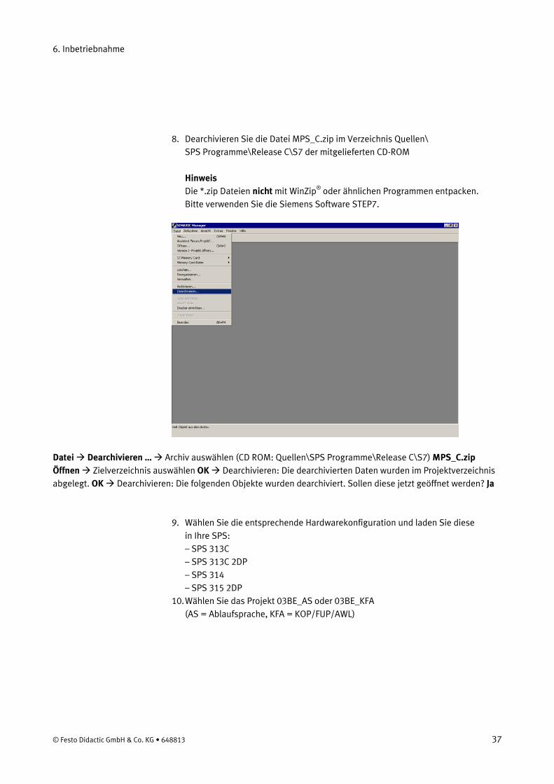
8. Dearchivieren Sie die Datei MPS_C.zip im Verzeichnis Quellen\ SPS Programme\Release C\S7 der mitgelieferten CD-ROM Hinweis Die *.zip Dateien nicht mit WinZip® oder ähnlichen Programmen entpacken. Bitte verwenden Sie die Siemens Software STEP7.
Datei Dearchivieren … Archiv auswählen (CD ROM: Quellen\SPS Programme\Release C\S7) MPS_C.zip Öffnen Zielverzeichnis auswählen OK Dearchivieren: Die dearchivierten Daten wurden im Projektverzeichnis abgelegt. OK Dearchivieren: Die folgenden Objekte wurden dearchiviert. Sollen diese jetzt geöffnet werden? Ja
9. Wählen Sie die entsprechende Hardwarekonfiguration und laden Sie diese in Ihre SPS: – SPS 313C – SPS 313C 2DP – SPS 314 – SPS 315 2DP
10. Wählen Sie das Projekt 03BE_AS oder 03BE_KFA (AS = Ablaufsprache, KFA = KOP/FUP/AWL)
© Festo Didactic GmbH & Co. KG • 648813 37
6. Inbetriebnahme
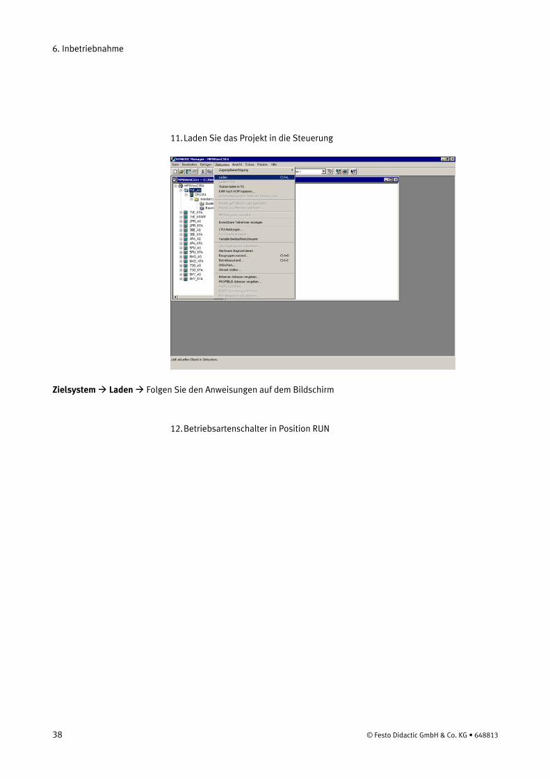
11. Laden Sie das Projekt in die Steuerung
Zielsystem Laden Folgen Sie den Anweisungen auf dem Bildschirm
12. Betriebsartenschalter in Position RUN
38 © Festo Didactic GmbH & Co. KG • 648813
6. Inbetriebnahme
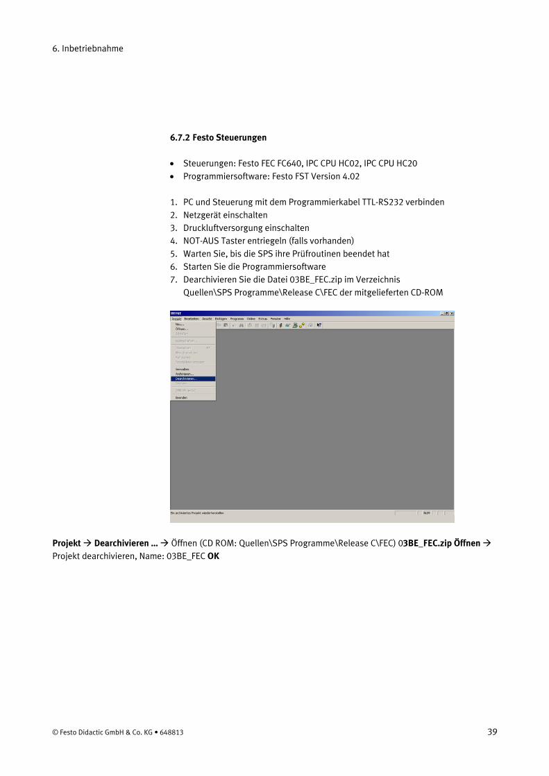
6.7.2 Festo Steuerungen
• Steuerungen: Festo FEC FC640, IPC CPU HC02, IPC CPU HC20 • Programmiersoftware: Festo FST Version 4.02
1. PC und Steuerung mit dem Programmierkabel TTL-RS232 verbinden 2. Netzgerät einschalten 3. Druckluftversorgung einschalten 4. NOT-AUS Taster entriegeln (falls vorhanden) 5. Warten Sie, bis die SPS ihre Prüfroutinen beendet hat 6. Starten Sie die Programmiersoftware 7. Dearchivieren Sie die Datei 03BE_FEC.zip im Verzeichnis
Quellen\SPS Programme\Release C\FEC der mitgelieferten CD-ROM
Projekt Dearchivieren … Öffnen (CD ROM: Quellen\SPS Programme\Release C\FEC) 03BE_FEC.zip Öffnen Projekt dearchivieren, Name: 03BE_FEC OK
© Festo Didactic GmbH & Co. KG • 648813 39
6. Inbetriebnahme
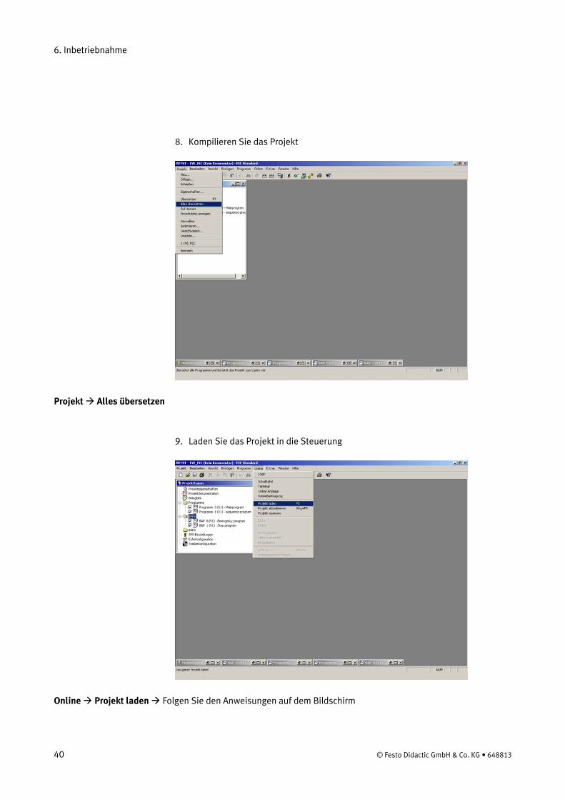
8. Kompilieren Sie das Projekt
Projekt Alles übersetzen
9. Laden Sie das Projekt in die Steuerung
Online Projekt laden Folgen Sie den Anweisungen auf dem Bildschirm
40 © Festo Didactic GmbH & Co. KG • 648813
6. Inbetriebnahme
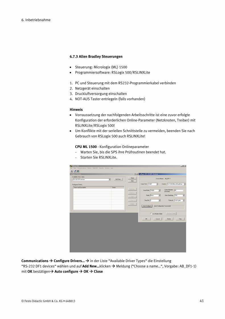
6.7.3 Allen Bradley Steuerungen
• Steuerung: Micrologix (ML) 1500 • Programmiersoftware: RSLogix 500/RSLINXLite
1. PC und Steuerung mit dem RS232-Programmierkabel verbinden 2. Netzgerät einschalten 3. Druckluftversorgung einschalten 4. NOT-AUS Taster entriegeln (falls vorhanden)
Hinweis • Vorraussetzung der nachfolgenden Arbeitsschritte ist eine zuvor erfolgte
Konfiguration der erforderlichen Online-Parameter (Netzknoten, Treiber) mit RSLINXLite/RSLogix 500!
• Um Konflikte mit der seriellen Schnittstelle zu vermeiden, beenden Sie nach Gebrauch von RSLogix 500 auch RSLINXLite! CPU ML 1500 - Konfiguration Onlineparameter – Warten Sie, bis die SPS ihre Prüfroutinen beendet hat. – Starten Sie RSLINXLite.
Communications Configure Drivers… in der Liste “Available Driver Types“ die Einstellung “RS-232 DF1 devices“ wählen und auf Add New…klicken Meldung (“Choose a name…“, Vorgabe: AB_DF1-1) mit OK bestätigen Auto configure OK Close
© Festo Didactic GmbH & Co. KG • 648813 41

6. Inbetriebnahme
– Starten Sie RSLogix 500.
Comms System Comms… Steuerung in der Liste markieren und mit OK bestätigen
5. SPS Speicher löschen: – Warten Sie, bis die SPS ihre Prüfroutinen beendet hat. CPU ML 1500 – Stellen Sie den Betriebsartenschalter auf REM bzw. PROG. – Starten Sie die Programmiersoftware. – Wählen Sie im Menü Comms System Comms… Steuerung markieren
und Online klicken. – Nach erfolgtem Verbindungsaufbau wählen Sie nun im Menü Comms Clear
Processor Memory und bestätigen Sie mit OK. – Wenn die COMM 0.-LED erlischt, ist der Speicher der SPS gelöscht und zum
Laden der Programme bereit. 6. Öffnen Sie die Projektdatei 03_BE_K im Verzeichnis Quellen\
SPS Programme\Release C\ML 1500 der mitgelieferten CD-ROM.
42 © Festo Didactic GmbH & Co. KG • 648813

6. Inbetriebnahme
File Open … Projektdatei auswählen (CD ROM: Quellen\SPS Programme\Release C\ML 1500) 03_BE_K Öffnen
7. Laden Sie das Projekt in die Steuerung
Comms. System Comms. Steuerung auswählen, auf Download klicken. Bestätigen Sie die nachfolgenden Meldungen ("Revision note","…sure to proceed with Download?", "…want to go online?") mit Ja bzw. OK
8. Betriebsartenschalter in Position REM bzw. RUN
© Festo Didactic GmbH & Co. KG • 648813 43
6. Inbetriebnahme
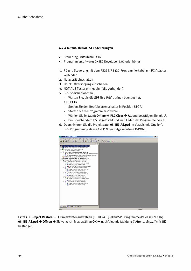
6.7.4 Mitsubishi/MELSEC Steuerungen
• Steuerung: Mitsubishi FX1N • Programmiersoftware: GX IEC Developer 6.01 oder höher
1. PC und Steuerung mit dem RS232/RS422-Programmierkabel mit PC-Adapter
verbinden 2. Netzgerät einschalten 3. Druckluftversorgung einschalten 4. NOT-AUS Taster entriegeln (falls vorhanden) 5. SPS Speicher löschen:
– Warten Sie, bis die SPS ihre Prüfroutinen beendet hat. CPU FX1N – Stellen Sie den Betriebsartenschalter in Position STOP. – Starten Sie die Programmiersoftware. – Wählen Sie im Menü Online PLC Clear All und bestätigen Sie mit JA. – Der Speicher der SPS ist gelöscht und zum Laden der Programme bereit.
6. Dearchivieren Sie die Projektdatei 03_BE_AS.pcd im Verzeichnis Quellen\ SPS Programme\Release C\FX1N der mitgelieferten CD-ROM.
Extras Project Restore … Projektdatei auswählen (CD ROM: Quellen\SPS Programme\Release C\FX1N) 03_BE_AS.pcd Öffnen Zielverzeichnis auswählen OK nachfolgende Meldung (“After saving,…”)mit OK bestätigen
44 © Festo Didactic GmbH & Co. KG • 648813
6. Inbetriebnahme
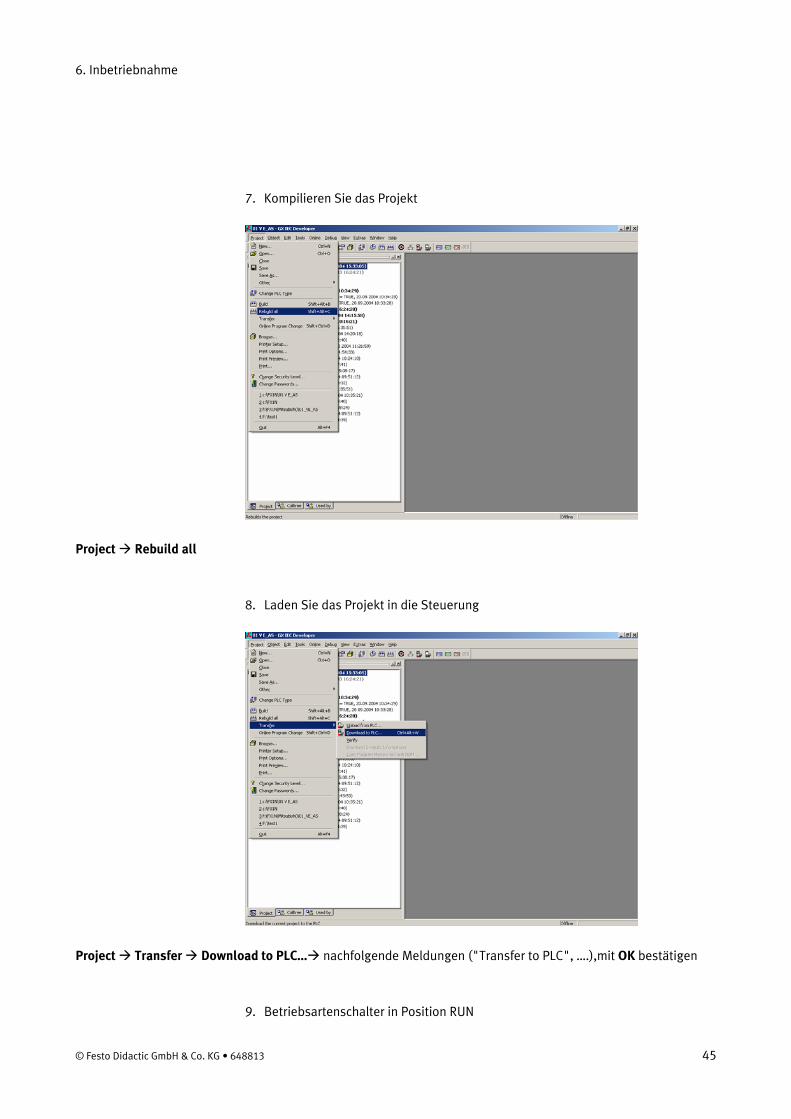
7. Kompilieren Sie das Projekt
Project Rebuild all
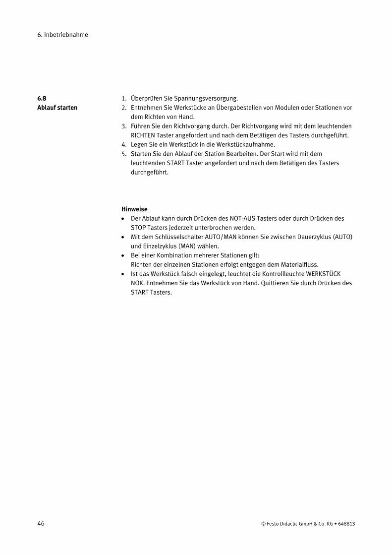
8. Laden Sie das Projekt in die Steuerung
Project Transfer Download to PLC… nachfolgende Meldungen ("Transfer to PLC", ….),mit OK bestätigen
9. Betriebsartenschalter in Position RUN
© Festo Didactic GmbH & Co. KG • 648813 45
6. Inbetriebnahme
1. Überprüfen Sie Spannungsversorgung. 6.8 Ablauf starten 2. Entnehmen Sie Werkstücke an Übergabestellen von Modulen oder Stationen vor
dem Richten von Hand. 3. Führen Sie den Richtvorgang durch. Der Richtvorgang wird mit dem leuchtenden
RICHTEN Taster angefordert und nach dem Betätigen des Tasters durchgeführt. 4. Legen Sie ein Werkstück in die Werkstückaufnahme. 5. Starten Sie den Ablauf der Station Bearbeiten. Der Start wird mit dem
leuchtenden START Taster angefordert und nach dem Betätigen des Tasters durchgeführt.
Hinweise • Der Ablauf kann durch Drücken des NOT-AUS Tasters oder durch Drücken des
STOP Tasters jederzeit unterbrochen werden. • Mit dem Schlüsselschalter AUTO/MAN können Sie zwischen Dauerzyklus (AUTO)
und Einzelzyklus (MAN) wählen. • Bei einer Kombination mehrerer Stationen gilt:
Richten der einzelnen Stationen erfolgt entgegen dem Materialfluss. • Ist das Werkstück falsch eingelegt, leuchtet die Kontrollleuchte WERKSTÜCK
NOK. Entnehmen Sie das Werkstück von Hand. Quittieren Sie durch Drücken des START Tasters.
46 © Festo Didactic GmbH & Co. KG • 648813
6. Inbetriebnahme
6.9.1 Vernetzung 6.9 Kombination von Stationen
In der Standardversion werden MPS® Stationen mit optischen Sensoren gekoppelt. Diese Art der Kopplung wird mit StationLink bezeichnet. Als StationLink Sensoren werden Einweg-Lichtschranken Sender und Empfänger verwendet. Der StationLink Sender ist auf der Materialeingangsseite der Station montiert, der StationLink Empfänger auf der Materialausgangsseite. Durch Ein- bzw. Ausschalten des StationLink Senders signalisiert die Station der Vorgängerstation, ob sie zur Aufnahme eines Werkstückes bereit ist oder ob sie belegt ist.
Die Sensoren zur Verkettung mehrerer Stationen müssen sich gegenüberstehen und fluchten. Die verketteten Stationen müssen über die Verbindungselemente mit Hammerkopfschrauben sicher miteinander verbunden sein.
Hinweis Bei der Station Verteilen ist nur der StationLink Empfänger montiert. Bei der Station Sortieren ist nur der StationLink Sender montiert.
© Festo Didactic GmbH & Co. KG • 648813 47

6. Inbetriebnahme
48 © Festo Didactic GmbH & Co. KG • 648813

7. Wartung
Die Station Bearbeiten ist weitestgehend wartungsfrei. In regelmäßigen Abständen sollten
• die aktiven Flächen der Näherungsschalter • die gesamte Station
mit einem weichen, fuselfreien Tuch oder Pinsel gereinigt werden.
Es dürfen keine aggressiven oder scheuernde Reinigungsmittel verwendet werden.
© Festo Didactic GmbH & Co. KG • 648813 49

7. Wartung
50 © Festo Didactic GmbH & Co. KG • 648813
Inhalt der CD-ROM
Hinweis Alle aufgelisteten Dokumente und Medien sind auf der mitgelieferten CD ROM (665871) im Verzeichnis Deutsch\3_Bearbeiten gespeichert.
Montageanleitungen Station Bearbeiten
Betriebsmittel Station Bearbeiten
Schaltpläne Station Bearbeiten, elektrisch
Programmierung GRAFCET Station Bearbeiten
Stücklisten Station Bearbeiten
Videos Station Bearbeiten, Real
© Festo Didactic GmbH & Co. KG • 648813 51

Inhalt der CD-ROM
Bedienungsanleitungen Lichtschranke, Empfänger 369 662 Lichtschranke, Sender 369 679
Datenblätter Bohrmaschine 326 395 E/A Terminal 034 035 Getriebemotor Bohren 526 867 Getriebemotor Rundschalttisch 652 345 Lichtschranke, Empfänger 165 323 Lichtschranke, Sender 165 353 Linearachse mit Zahnriemenantrieb DGEL-12 654 152 Microschalter S-3-E 007 347 Näherungsschalter SIEN-M8 150 395 Näherungsschalter, kapazitiv 178 575 Relais 268 327 Steckdose mit Anschlusskabel SIM-M8-3GD 159 420 Steckdose mit Anschlusskabel SIM-M8-4GD 158 960
52 © Festo Didactic GmbH & Co. KG • 648813

Aktualisierungen
Aktuelle Informationen und Ergänzungen zur Technischen Dokumentation der MPS® Stationen finden Sie im Internet unter der Adresse:
http://www.festo-didactic.de/Services > MPS
© Festo Didactic GmbH & Co. KG • 648813 53

Aktualisierungen
54 © Festo Didactic GmbH & Co. KG • 648813
Contents
1. Introduction__________________________________________________ 57 1.1 Training contents ______________________________________________ 58 1.2 Important notes _______________________________________________ 59 1.3 Duty of the operating authority___________________________________ 59 1.4 Duty of trainees _______________________________________________ 59 1.5 Risks involved in dealing with the Modular Production System _________ 60 1.6 Warranty and liability __________________________________________ 61 1.7 Intended use _________________________________________________ 61 2. Notes on safety _______________________________________________ 63 3. Technical data ________________________________________________ 65 3.1 Combinations_________________________________________________ 65 4. Transport/Unpacking/Scope of delivery __________________________ 67 5. Design and function ___________________________________________ 69 5.1 The Processing station _________________________________________ 69 5.2 Function _____________________________________________________ 71 5.3 Sequence description __________________________________________ 71 5.4 Rotary indexing table module ____________________________________ 73 5.5 Testing module _______________________________________________ 74 5.6 Drilling module _______________________________________________ 75 6. Commissioning _______________________________________________ 77 6.1 Workstation __________________________________________________ 77 6.2 Mechanical set up _____________________________________________ 78 6.2.1 Assembling profile plate and control console _______________________ 78 6.2.2 Assembling the station _________________________________________ 79 6.3 Adjust sensors ________________________________________________ 80 6.3.1 Capacitive proximity sensor (Rotary indexing table, detection of workpiece) _____________________ 80 6.3.2 Inductive proximity sensor (Rotary indexing table, Positioning)_________ 81 6.3.3 Inductive proximity sensor (Testing, orientation of workpiece) _________ 82 6.3.4 Micro switch (Drilling, linear axis)_________________________________ 83 6.4 Visual check __________________________________________________ 84
© Festo Didactic GmbH & Co. KG • 648813 55
Contents
6.5 Cable connections _____________________________________________ 85 6.6 Voltage supply ________________________________________________ 86 6.7 Loading the PLC program _______________________________________ 86 6.71 Siemens controller_____________________________________________ 86 6.7.2 Festo controller _______________________________________________ 89 6.7.3 Allen Bradley controller _________________________________________ 91 6.7.4 Mitsubishi/MELSEC controller ___________________________________ 94 6.8 Starting the sequence __________________________________________ 96 6.9 Combination of stations ________________________________________ 97 6.9.1 Networking___________________________________________________ 97 7. Maintenance _________________________________________________ 99 Content of the CD-ROM ______________________________________________ 101 Assembly instructions _________________________________________ 101 Circuit diagrams______________________________________________ 101 Programming ________________________________________________ 101 Parts lists ___________________________________________________ 101 Videos______________________________________________________ 101 Operating instructions_________________________________________ 102 Data sheets _________________________________________________ 102 Updates _________________________________________________________ 103
56 © Festo Didactic GmbH & Co. KG • 648813

1. Introduction
The Festo Didactic Learning System for Automation is designed to meet a number of different training and vocational requirements. The systems and stations of the Modular Production System (MPS®) facilitate industry-orientated vocational and further training and the hardware consists of didactically suitable industrial components.
The Processing station provides you with an appropriate system for practice-orientated tuition of the following key qualifications
• Social competence, • Technical competence and • Methodological competence
Moreover, training can be provided to instil team spirit, willingness to cooperate and organisational skills.
Actual project phases can be taught by means of training projects, such as:
• Planning, • Assembly, • Programming, • Commissioning, • Operation, • Maintenance and • Fault finding.
© Festo Didactic GmbH & Co. KG • 648813 57
1. Introduction
1.1 Training contents
Training contents covering the following subjects can be taught:
• Mechanics – Mechanical assembly of a station
• Electrical – Correct wiring of electrical components – Relay control (control section/power section)
• Handling technology – Checking the correctly positioned workpiece input
• Sensors – Correct use of limit switches
• PLC – Programming of logic control systems – Programming of parallel step sequences
• Commissioning – Commissioning of a production system
• Fault finding – Systematic fault finding on a production system
Topics for project work
• Reversing contactor circuit • Selecting linear drives
58 © Festo Didactic GmbH & Co. KG • 648813
1. Introduction
The basic requirement for safe use and trouble-free operation of the MPS® is to observe the fundamental safety recommendations and regulations.
1.2 Important notes
This manual contain important notes concerning the safe operation of the MPS®.
The safety recommendations in particular must be observed by anyone working on the MPS®.
Furthermore, the rules and regulations for the prevention of accidents applicable to the place of use must be observed.
The operating authority undertakes to ensure that the MPS® is used only by persons who:
1.3 Duty of the operating authority
• are familiar with the basic regulations regarding operational safety and accident prevention and who have received instructions in the handling of the MPS®,
• have read and understood the chapter on safety and the cautionary notes in this manual.
Safety-conscious working of the persons should be regularly vetted.
Prior to commencing work, all persons assigned to working on the MPS® have a duty to:
1.4 Duty of trainees
• read the chapter on safety and the cautionary notes in this manual and, • observe the basic regulations regarding operational safety and the prevention of
accidents.
© Festo Didactic GmbH & Co. KG • 648813 59
1. Introduction
The MPS® is designed according to state of the art technology and in compliance with recognised safety regulations. However when using the system there is nevertheless a risk of physical or fatal injury to the user or third parties or of damage being caused to the machinery or other material assets.
1.5 Risks involved in dealing with the Modular Production System
The MPS® is to be used only:
• for its intended purpose and • in an absolutely safe conditions.
Faults impairing safety must be rectified immediately!
60 © Festo Didactic GmbH & Co. KG • 648813
1. Introduction
1.6 Warranty and liability
In principle all our „Terms and Conditions of Sale“ apply. These are available to the operating authority upon conclusion of the contract at the latest. Warranty and liability claims for persons or material damage are excluded if these can be traced back to one or several of the following causes:
• Use of the MPS® not in accordance with its intended purpose • Incorrect assembly, commissioning, operation and maintenance of the MPS® • Operation of the MPS® using faulty safety equipment or incorrectly fitted or non
operational safety or protective devices • Non observance of notes in the manual regarding transport, storage, assembly,
commissioning, operation, maintenance and setting up of the MPS® • Unlawful constructional modifications on the MPS® • Inadequate monitoring of components subject to wear • Incorrectly carried out repairs • Catastrophies as a result of foreign bodies and vis major.
Festo Didactic herewith rules out any liability for damage or injury to trainees, the training company and/or other third parties which may occur during the use/operation of the system other than purely in a training situation, unless such damage has been caused intentionally or due to gross negligence by Festo Didactic.
1.7 Intended use
This system has been developed and produced exclusively for vocational and further training in the field of automation and technology. The training authority and/or the instructors is/are to ensure that trainees observe the safety precautions described in the manual provided.
The use of the system for its intended purpose also includes:
• following all advice in the manual and • carrying out inspection and maintenance work.
© Festo Didactic GmbH & Co. KG • 648813 61

1. Introduction
62 © Festo Didactic GmbH & Co. KG • 648813
2. Notes on safety
General • Trainees must only work on the station under the supervision of an instructor. • Observe the data in the data sheets for the individual components, in particular
all notes on safety!
Electrics • Electrical connections are to be wired up or disconnected only when power is
disconnected! • Use only low voltages of up to 24 V DC.
Mechanics • Securely mount all components on the plate. • No manual intervention unless the machine is at rest.
Drilling machine • The drilling machine is operational. Therefore, stay at a safe distance from the
rotating spindle! • The polishing process is merely simulated for reasons of safety.
© Festo Didactic GmbH & Co. KG • 648813 63

2. Notes on safety
64 © Festo Didactic GmbH & Co. KG • 648813

3. Technical data
Parameter Value
Voltage supply 24 V DC, 4.5 A
Digital inputs 8
Digital outputs 8
3.1 Combinations
Possible direct MPS®
downstream stations
MPS®
station
Testing
(PR)
Proces-
sing
(BE)
Hand-
ling
(HA)
Buffer
(PU)
Pick&
Place
(PP)
Fluidic-
Muscle
Press
(FP)
Separat-
ing
(TR)
Storing
(LA)
Robot
(R)
Assembly*
(MO/HS)
Sorting**
(SO)
Distributing***
(VE)
Testing
(PR)
Processing
(BE)
Handling
(HA)
Buffer
(PU)
Pick&Place
(PP)
FluidicMuscle
Press (FP)
Separating
(TR)
Storing
(LA)
Robot
(R)
Assembly*
(MO/HS)
* Assembly with Punching / ** Sorting DP / *** Distributing AS-Interface
© Festo Didactic GmbH & Co. KG • 648813 65

3. Technical data
66 © Festo Didactic GmbH & Co. KG • 648813
4. Transport/Unpacking/Scope of delivery
Transport The MPS® is delivered in a container with a pallet base.
The container must be transported on a suitable fork lift truck at all times and must be secured against tipping or falling off.
The carrier and Festo Didactic are to be notified immediately of any damage caused during transport.
Unpacking Carefully remove the padding material in the container box when unpacking the station. When unpacking the station, make sure that none of the station assemblies have been damaged.
Check the station for any possible damaged once unpacked. The carrier and Festo Didactic are to be notified immediately of any damage.
Scope of delivery Check the scope of delivery against the delivery note and the order. Festo Didactic must be notified immediately of any discrepancies.
© Festo Didactic GmbH & Co. KG • 648813 67

4. Transport/Unpacking/Scope of delivery
68 © Festo Didactic GmbH & Co. KG • 648813
5. Design and function
5.1 The Processing station
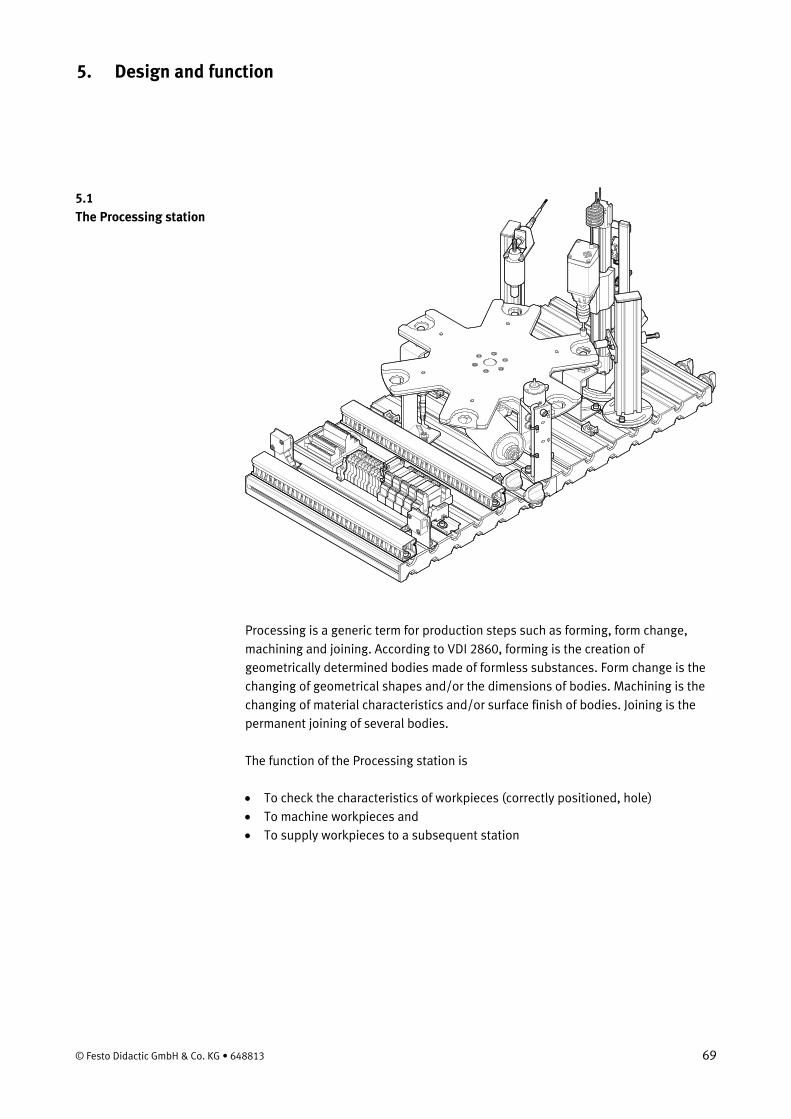
Processing is a generic term for production steps such as forming, form change, machining and joining. According to VDI 2860, forming is the creation of geometrically determined bodies made of formless substances. Form change is the changing of geometrical shapes and/or the dimensions of bodies. Machining is the changing of material characteristics and/or surface finish of bodies. Joining is the permanent joining of several bodies.
The function of the Processing station is
• To check the characteristics of workpieces (correctly positioned, hole) • To machine workpieces and • To supply workpieces to a subsequent station
© Festo Didactic GmbH & Co. KG • 648813 69

5. Design and function
The Processing station consists of the following • Rotary indexing table module • Testing module • Drilling module • Clamping module • Sorting gate module, electrical • Profile plate
• Trolley • Control console • PLC board
Processing station with trolley, control console and PLC board
70 © Festo Didactic GmbH & Co. KG • 648813
5. Design and function
5.2 Function
In the processing station, workpieces are tested and processed on a rotary indexing table. The rotary indexing table is driven by a DC motor. The table is positioned by a relay circuit, with the position of the table being detected by an inductive sensor.
On the rotary indexing table, the workpieces are tested and drilled in two parallel processes. A solenoid actuator with an inductive sensor checks that the workpieces are inserted in the correct position. During drilling, the workpiece is clamped by a solenoid actuator.
Finished workpieces are passed on via the electrical ejector.
Note The station uses exclusively electrical actuators.
5.3 Sequence description
Starting prerequisites • Workpiece is in the workpiece retainer material input
Initial position • Rotary indexing table positioned • Checking solenoid plunger raised • Drilling machine in raised position • Drilling machine motor is switched off • Clamping device retracted • Electrical branch not actuated
© Festo Didactic GmbH & Co. KG • 648813 71
5. Design and function
Sequence
1. The rotary indexing table is rotated by 60°, if a workpiece is detected in the workpiece retainer 1 and the START pushbutton is pressed.
2. The solenoid plunger moves downwards and checks whether the workpiece is inserted with the opening facing upwards. The rotary indexing table is rotated by 60° if the result of the check is OK.
3. The clamping device clamps the workpiece. The motor of the drilling machine is switched on. The linear axis moves the drilling machine downwards.
4. When the drilling machine has reached its lower position, it is moved to its upper stop again by the linear axis.
5. The motor of the drilling machine is switched off and the clamping device is retracted. The rotary indexing table is rotated by 60°.
6. The electrical sorting gate passes on the workpiece to a subsequent station.
This sequence describes the passage of one workpiece through the Processing station. The workpiece is in the transfer position to a downstream station. The processing cycle can be started again, once a workpiece is inserted in the workpiece retainer 1.
72 © Festo Didactic GmbH & Co. KG • 648813
5. Design and function
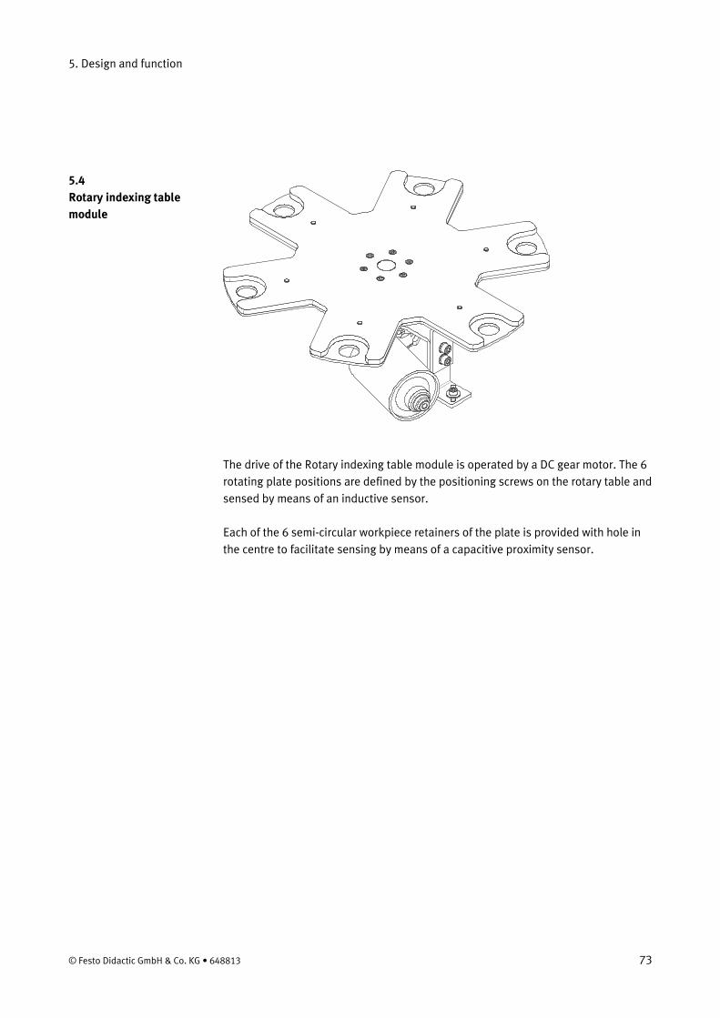
5.4 Rotary indexing table module
The drive of the Rotary indexing table module is operated by a DC gear motor. The 6 rotating plate positions are defined by the positioning screws on the rotary table and sensed by means of an inductive sensor.
Each of the 6 semi-circular workpiece retainers of the plate is provided with hole in the centre to facilitate sensing by means of a capacitive proximity sensor.
© Festo Didactic GmbH & Co. KG • 648813 73

5. Design and function
5.5 Testing module
An inserted workpiece is checked for correct positioning. If the hole points upwards, then the armature of the testing solenoid reaches its end position.
An inductive proximity sensor is actuated via a nut at the upper end of the armature.
74 © Festo Didactic GmbH & Co. KG • 648813

5. Design and function
5.6 Drilling module
The Drilling module is used to simulate the polishing of the hole of the workpiece.
An electrical clamping device retains the workpiece. The feed and return actions of the drilling machine are effected by means of a linear axis with toothed belt drive. An electrical gear motor drives the linear axis and a relay circuit is used to activate the motor.
The motor of the drilling machine is operated via 24 V DC and the speed is not adjustable.
The end position sensing is effected by means of electrical limit switches. Approaching of the limit switches causes a reversal of the direction of movement of the linear axis.
© Festo Didactic GmbH & Co. KG • 648813 75

5. Design and function
76 © Festo Didactic GmbH & Co. KG • 648813
6. Commissioning
The stations of the MPS® are generally delivered
• completely assembled • operationally adjusted as single station • commissioned • tested
Note If stations are combined changes of the mechanical set-up and the position and setting of sensors may be necessary.
The commissioning is normally limited to a visual check to ensure correct tubing connections / wiring and supply of operating voltage.
All components, tubing and wiring is clearly marked so that all connections can be easily re-established.
The following is required to commission the MPS® station: 6.1 Workstation
• The assembled and adjusted MPS® station • A control console • A PLC board • A power supply unit 24 V DC, 4.5 A • A compressed air supply of 6 bar (600 kPa), approx. suction capacity of 50 l/min • A PC with installed PLC programming software
© Festo Didactic GmbH & Co. KG • 648813 77

6. Commissioning
6.2.1 Assembling profile plate and control console 6.2 Mechanical set up
1
2 (4x)
4 (4x)
3
5 (2x)
6
1 Profile plate 2 T-head nut M6 x-32 (4x) 3 Trolley 4 Socket head screw M6x10 (4x) 5 Screw 3.5x9 (2x) 6 Control console
78 © Festo Didactic GmbH & Co. KG • 648813

6. Commissioning
6.2.2 Assembling the station
Instructions on assembling the station please find in the assembly instructions of the Processing station in the directory English\3_Processing\Assembly instructions on the CD-ROM supplied.
© Festo Didactic GmbH & Co. KG • 648813 79

6. Commissioning
6.3.1 Capacitive proximity sensor (Rotary indexing table, detection of workpiece) 6.3 Adjust sensors
The capacitive proximity sensor is used for detection of workpieces. The workpiece changes the capacity of a capacitor build in the sensor head. Workpieces are detected independent of colour and material.
Note Capacitive proximity sensors are used in the positions material input, testing and drilling.
Prerequisite – The Rotary indexing table module is assembled. – Proximity sensor is wired up. – Power supply unit switched on.
Execution 1. Place a workpiece into the workpiece retainer. 2. Assemble the proximity sensor in the mounting bracket, avoid contact with the
rotary indexing table. Position the proximity sensor centred below the drill hole of the workpiece retainer.
3. Adjust the distance proximity sensor – workpiece until the switching status display switches to on. Note Avoid activation of the proximity sensor by the rotating plate of the rotary indexing table.
4. Check position and setting of the proximity sensor (place/pick up workpieces).
Documents • Data sheets
Proximity sensor, capacitive (178575) in the directory English\3_Processing\Data sheets on the CD-ROM supplied.
• Assembly instructions Processing station in the directory English\3_Processing\Assembly instructions on the CD-ROM supplied.
80 © Festo Didactic GmbH & Co. KG • 648813
6. Commissioning
6.3.2 Inductive proximity sensor (Rotary indexing table, Positioning)
The inductive proximity sensor is used for positioning of the rotary indexing table. Inductive proximity sensors detect metallic objects. The switching distance is a function of material and surface finish.
Prerequisite – The Rotary indexing table module is assembled. – Proximity sensor is wired up. – Power supply unit switched on.
Execution 1. Assemble the proximity sensor in the mounting bracket. Position the proximity
sensor centred below the positioning screw of the rotary indexing table. The distance proximity sensor – positioning screw is about 2 mm.
2. Adjust the distance proximity sensor – positioning screw until the switching status display switches to on.
3. Check position and setting of the proximity sensor by rotation of the rotary indexing table.
Documents • Data sheets
Proximity sensor, inductive (150395) in the directory English\3_Processing\Data sheets on the CD-ROM supplied.
• Assembly instructions Processing station in the directory English\3_Processing\Assembly instructions on the CD-ROM supplied.
© Festo Didactic GmbH & Co. KG • 648813 81
6. Commissioning
6.3.3 Inductive proximity sensor (Testing, orientation of workpiece)
The inductive proximity sensor is used for testing the orientation of the workpieces. Inductive proximity sensors detect metallic objects. The switching distance is a function of material and surface finish.
Prerequisite – The Rotary indexing table module and the Testing module are assembled. – Testing module and proximity sensor are wired up. – Power supply unit switched on.
Execution 1. Place a workpiece into the workpiece retainer. The hole points upwards. 2. Switch on the power supply of the coil of the Testing module. 3. Position the inductive proximity sensor in a distance of about 1 mm to the nut of
the feeler of the Testing module. 4. Adjust the distance proximity sensor – nut until the switching status display
switches to on. 5. Check position and setting of the proximity sensor by switching on and off the
coil of the Testing module.
Documents • Data sheets
Proximity sensor, inductive (150395) in the directory English\3_Processing\Data sheets on the CD-ROM supplied.
• Assembly instructions Processing station in the directory English\3_Processing\Assembly instructions on the CD-ROM supplied.
82 © Festo Didactic GmbH & Co. KG • 648813
6. Commissioning
6.3.4 Micro switch (Drilling, linear axis)
The micro switches are used for end stop sensing of the linear axis. The micro switches are actuated by the slide of the linear axis.
Prerequisite – The Drilling module is assembled. – Drilling module is wired up – Micro switches are wired up – Power supply unit switched on.
Execution 1. Move the drilling machine to the upper end stop. 2. Shift the micro switch in the mounting bracket oblong holes until it is actuated. 3. Fix the clamping screws. 4. Move the drilling machine to the lower end stop. 5. Shift the micro switch in the mounting bracket oblong holes until it is actuated. 6. Fix the clamping screws. 7. Start a test run to check if the micro switches are positioned correctly (move
drilling machine upwards/downwards).
Documents • Data sheets
Micro switch S-3-E (007347) in the directory English\3_Processing\Data sheets on the CD-ROM supplied.
• Assembly instructions Processing station and Drilling module in the directory English\3_Processing\Assembly instructions on the CD-ROM supplied.
© Festo Didactic GmbH & Co. KG • 648813 83

6. Commissioning
6.4 Visual check
A visual check must be carried out before each commissioning!
Prior to starting up the station, you will need to check:
• The electrical connections • The correct installation and condition of the compressed air connections • The mechanical components for visual defects
(tears, loose connections etc.)
Eliminate any damage detected prior to starting up the station!
84 © Festo Didactic GmbH & Co. KG • 648813
6. Commissioning
1
2
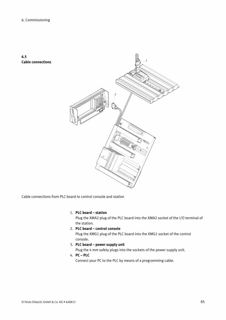
6.5 Cable connections
Cable connections from PLC board to control console and station
1. PLC board – station Plug the XMA2 plug of the PLC board into the XMA2 socket of the I/O terminal of the station.
2. PLC board – control console Plug the XMG1 plug of the PLC board into the XMG1 socket of the control console.
3. PLC board – power supply unit Plug the 4 mm safety plugs into the sockets of the power supply unit.
4. PC – PLC Connect your PC to the PLC by means of a programming cable.
© Festo Didactic GmbH & Co. KG • 648813 85
6. Commissioning
• The stations are supplied with 24 V DC voltage (max. 5 A) via a power supply unit.
6.6 Voltage supply
• The voltage supply of the complete station is effected via the PLC board.
6.7.1 Siemens controller 6.7 Loading the PLC program
• Controller: Siemens S7-313C, S7-313C-2DP, S7-314 or S7-315-2DP • Programming software: Siemens STEP7 Version 5.1 or higher
1. Connect PC and PLC using the RS232 programming cable with PC adapter 2. Switch on power supply unit 3. Switch on the compressed air supply 4. Release the EMERGENCY-STOP pushbutton (if available) 5. Overall reset PLC memory:
– Wait until the PLC has carried out its test routines. CPU 31xC – Press the mode selector switch to MRES. Keep the mode selector switch in
this position until the STOP LED comes on for the second time and stays on (this takes 3 sec.). You can let go of the mode selector.
– Within 3 sec. you must press the mode selector switch back to MRES. The STOP LED starts to flash rapidly and the CPU carries out a memory reset. You can let go of the mode selector.
– When the STOP LED comes on permanently again, the CPU has completed the memory reset.
– The data on the MMC (Micro Memory Card) are not deleted. This can be done by switching to the connected PLC via menu "PLC / Display Accessible Nodes" and deleting all blocks in the block folder.
CPU31x – Turn the mode selector switch to MRES and keep the mode selector switch in
this position until the STOP LED comes on for the second time and stays on. – Let go of the mode selector switch to STOP. Immediately you must turn the
mode selector switch back to MRES. The STOP LED starts to flash rapidly. – You can let go of the mode selector switch. – When the STOP LED comes on permanently the memory reset is completed. – The PLC is ready for program download.
6. mode selector switch in STOP position 7. Start the PLC programming software
86 © Festo Didactic GmbH & Co. KG • 648813
6. Commissioning
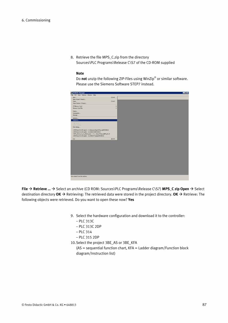
8. Retrieve the file MPS_C.zip from the directory Sources\PLC Programs\Release C\S7 of the CD-ROM supplied Note Do not unzip the following ZIP-Files using WinZip® or similar software. Please use the Siemens Software STEP7 instead.
File Retrieve … Select an archive (CD ROM: Sources\PLC Programs\Release C\S7) MPS_C zip Open Select destination directory OK Retrieving: The retrieved data were stored in the project directory. OK Retrieve: The following objects were retrieved. Do you want to open these now? Yes
9. Select the hardware configuration and download it to the controller: – PLC 313C – PLC 313C 2DP – PLC 314 – PLC 315 2DP
10. Select the project 3BE_AS or 3BE_KFA (AS = sequential function chart, KFA = Ladder diagram/Function block diagram/Instruction list)
© Festo Didactic GmbH & Co. KG • 648813 87

6. Commissioning
11. Download the project to the controller
PLC Download Follow the instructions on the screen
12. Turn the mode selector switch of the CPU to RUN position
88 © Festo Didactic GmbH & Co. KG • 648813
6. Commissioning
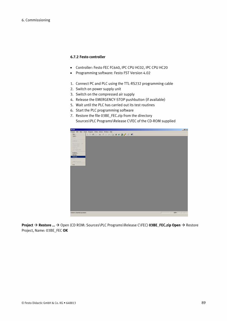
6.7.2 Festo controller
• Controller: Festo FEC FC640, IPC CPU HC02, IPC CPU HC20 • Programming software: Festo FST Version 4.02
1. Connect PC and PLC using the TTL-RS232 programming cable 2. Switch on power supply unit 3. Switch on the compressed air supply 4. Release the EMERGENCY-STOP pushbutton (if available) 5. Wait until the PLC has carried out its test routines 6. Start the PLC programming software 7. Restore the file 03BE_FEC.zip from the directory
Sources\PLC Programs\Release C\FEC of the CD-ROM supplied
Project Restore … Open (CD ROM: Sources\PLC Programs\Release C\FEC) 03BE_FEC.zip Open Restore Project, Name: 03BE_FEC OK
© Festo Didactic GmbH & Co. KG • 648813 89
6. Commissioning
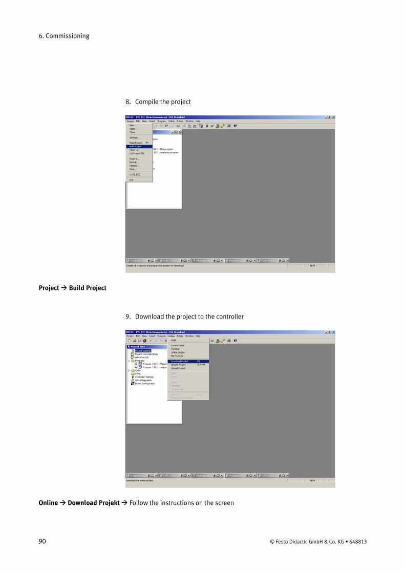
8. Compile the project
Project Build Project
9. Download the project to the controller
Online Download Projekt Follow the instructions on the screen
90 © Festo Didactic GmbH & Co. KG • 648813
6. Commissioning
6.7.3 Allen Bradley controller
• Controller: Micrologix (ML) 1500 • Programming software: RSLogix 500/RSLINXLite
1. Connect PC and PLC using the RS232 programming cable 2. Switch on power supply unit 3. Switch on the compressed air supply 4. Release the EMERGENCY-STOP pushbutton (if available)
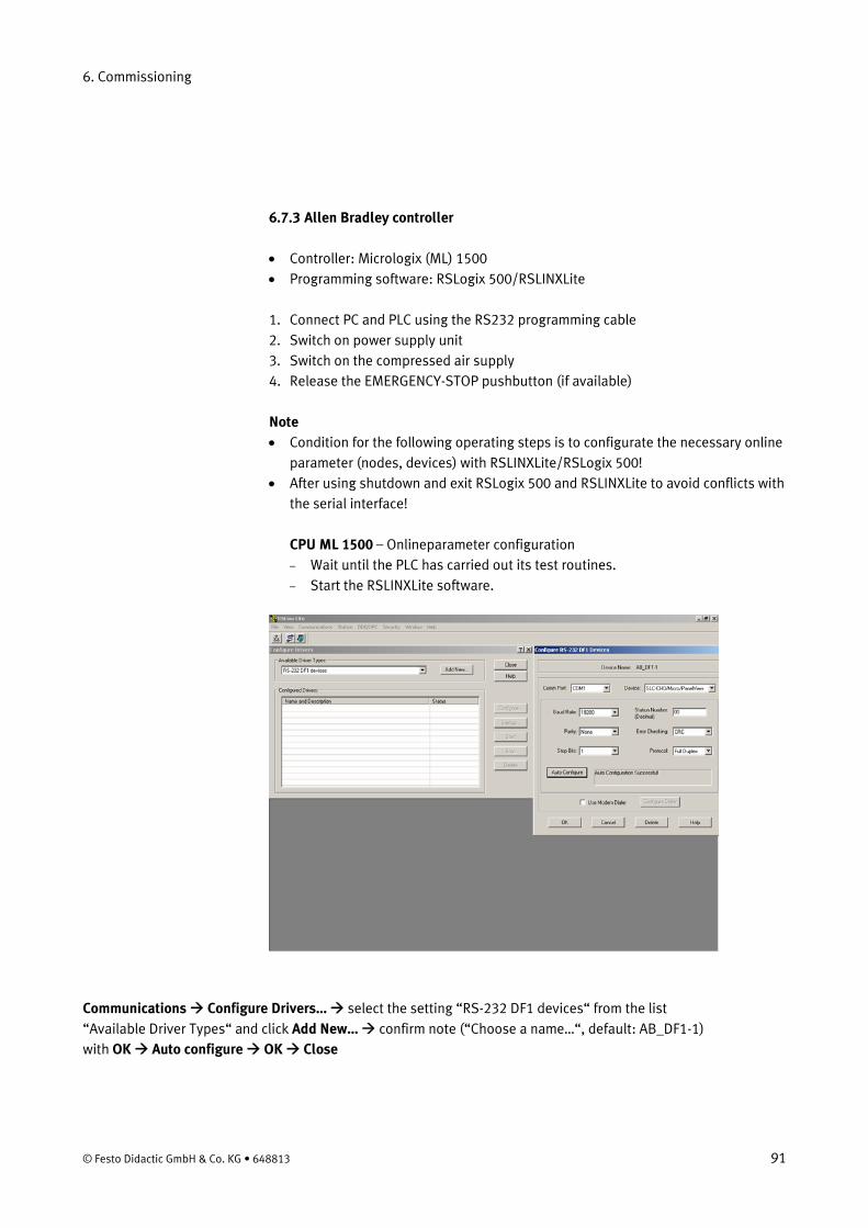
Note • Condition for the following operating steps is to configurate the necessary online
parameter (nodes, devices) with RSLINXLite/RSLogix 500! • After using shutdown and exit RSLogix 500 and RSLINXLite to avoid conflicts with
the serial interface! CPU ML 1500 – Onlineparameter configuration – Wait until the PLC has carried out its test routines. – Start the RSLINXLite software.
Communications Configure Drivers… select the setting “RS-232 DF1 devices“ from the list “Available Driver Types“ and click Add New… confirm note (“Choose a name…“, default: AB_DF1-1) with OK Auto configure OK Close
© Festo Didactic GmbH & Co. KG • 648813 91
6. Commissioning
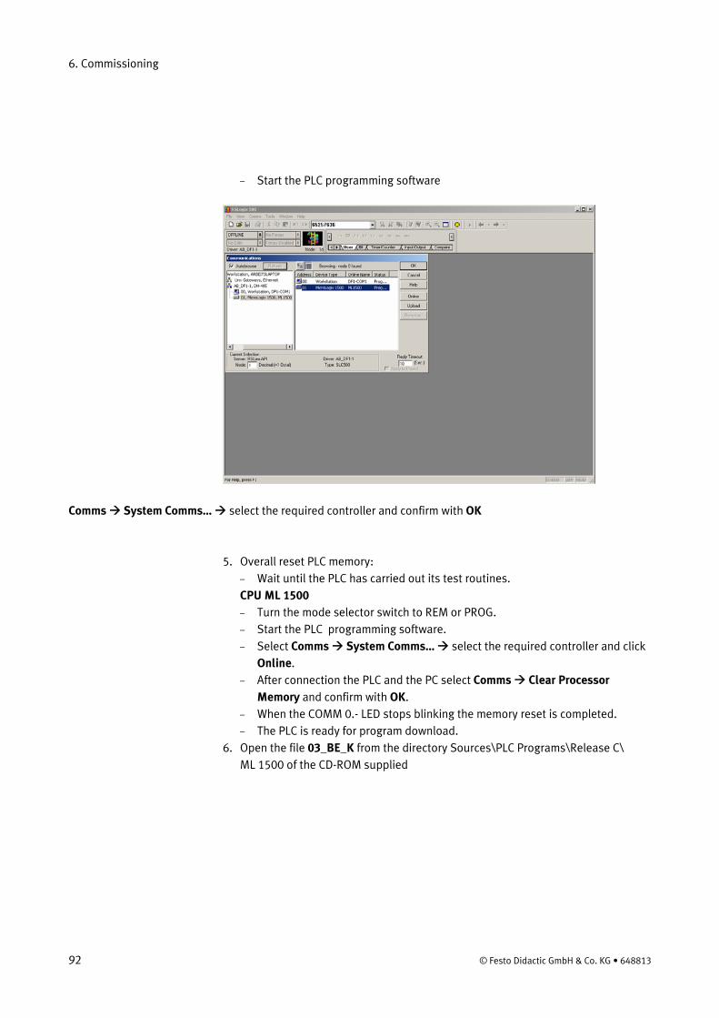
– Start the PLC programming software
Comms System Comms… select the required controller and confirm with OK
5. Overall reset PLC memory: – Wait until the PLC has carried out its test routines. CPU ML 1500 – Turn the mode selector switch to REM or PROG. – Start the PLC programming software. – Select Comms System Comms… select the required controller and click
Online. – After connection the PLC and the PC select Comms Clear Processor
Memory and confirm with OK. – When the COMM 0.- LED stops blinking the memory reset is completed. – The PLC is ready for program download.
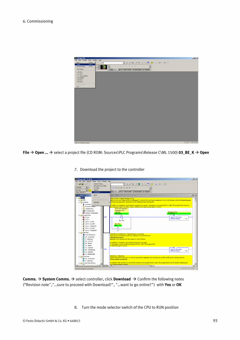
6. Open the file 03_BE_K from the directory Sources\PLC Programs\Release C\ ML 1500 of the CD-ROM supplied
92 © Festo Didactic GmbH & Co. KG • 648813
6. Commissioning
File Open … select a project file (CD ROM: Sources\PLC Programs\Release C\ML 1500) 03_BE_K Open
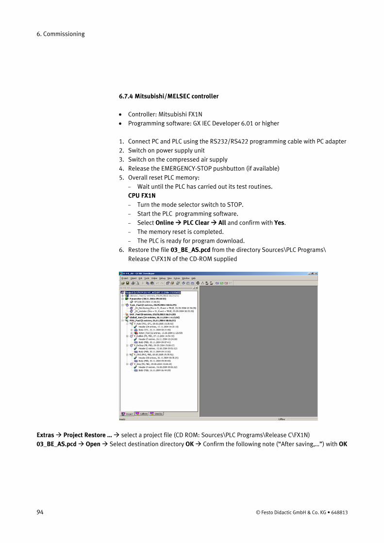
7. Download the project to the controller
Comms. System Comms. select controller, click Download Confirm the following notes (“Revision note","…sure to proceed with Download?", "…want to go online?") with Yes or OK
8. Turn the mode selector switch of the CPU to RUN position
© Festo Didactic GmbH & Co. KG • 648813 93
6. Commissioning
6.7.4 Mitsubishi/MELSEC controller
• Controller: Mitsubishi FX1N • Programming software: GX IEC Developer 6.01 or higher
1. Connect PC and PLC using the RS232/RS422 programming cable with PC adapter 2. Switch on power supply unit 3. Switch on the compressed air supply 4. Release the EMERGENCY-STOP pushbutton (if available) 5. Overall reset PLC memory:
– Wait until the PLC has carried out its test routines. CPU FX1N – Turn the mode selector switch to STOP. – Start the PLC programming software. – Select Online PLC Clear All and confirm with Yes. – The memory reset is completed. – The PLC is ready for program download.
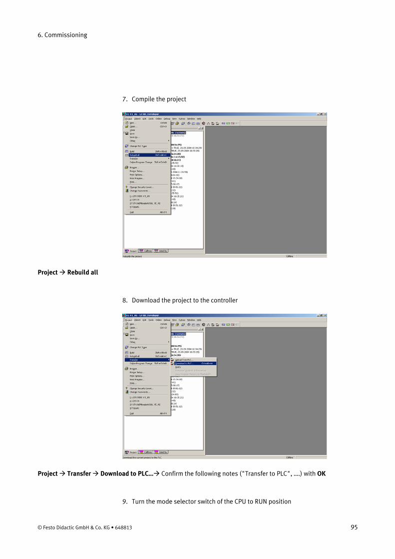
6. Restore the file 03_BE_AS.pcd from the directory Sources\PLC Programs\ Release C\FX1N of the CD-ROM supplied
Extras Project Restore … select a project file (CD ROM: Sources\PLC Programs\Release C\FX1N) 03_BE_AS.pcd Open Select destination directory OK Confirm the following note (“After saving,…”) with OK
94 © Festo Didactic GmbH & Co. KG • 648813
6. Commissioning
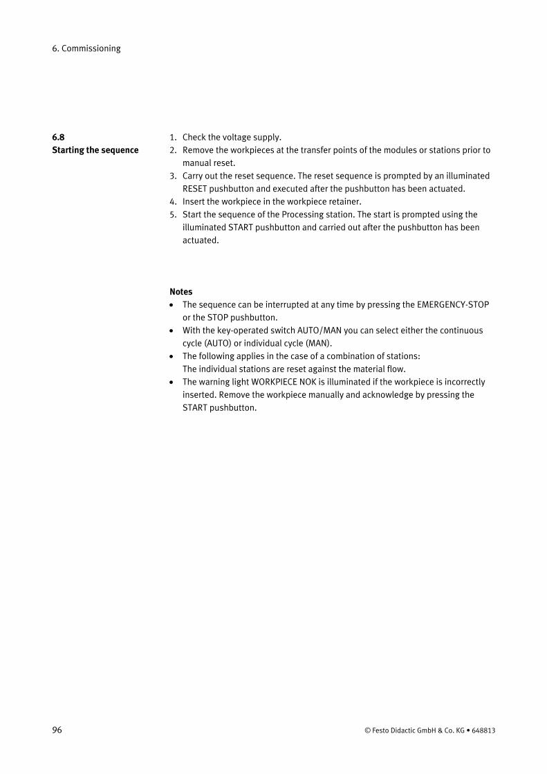
7. Compile the project
Project Rebuild all
8. Download the project to the controller
Project Transfer Download to PLC… Confirm the following notes ("Transfer to PLC", ….) with OK
9. Turn the mode selector switch of the CPU to RUN position
© Festo Didactic GmbH & Co. KG • 648813 95
6. Commissioning
1. Check the voltage supply. 6.8 Starting the sequence 2. Remove the workpieces at the transfer points of the modules or stations prior to
manual reset. 3. Carry out the reset sequence. The reset sequence is prompted by an illuminated
RESET pushbutton and executed after the pushbutton has been actuated. 4. Insert the workpiece in the workpiece retainer. 5. Start the sequence of the Processing station. The start is prompted using the
illuminated START pushbutton and carried out after the pushbutton has been actuated.
Notes • The sequence can be interrupted at any time by pressing the EMERGENCY-STOP
or the STOP pushbutton. • With the key-operated switch AUTO/MAN you can select either the continuous
cycle (AUTO) or individual cycle (MAN). • The following applies in the case of a combination of stations:
The individual stations are reset against the material flow. • The warning light WORKPIECE NOK is illuminated if the workpiece is incorrectly
inserted. Remove the workpiece manually and acknowledge by pressing the START pushbutton.
96 © Festo Didactic GmbH & Co. KG • 648813
6. Commissioning
6.9.1 Networking 6.9 Combination of stations
In the standard version, the MPS® stations are linked using optical sensors. This type of linking is known as StationLink, which uses through-beam sensor transmitters and receivers as sensors. The StationLink transmitter is mounted on the incoming material side and the StationLink receiver on the outgoing material side. By switching on or off the StationLink transmitter, the station signals the upstream station whether it is ready to receive a workpiece or busy.
The sensors for linking several stations must be arranged face to face in alignment. The linked stations must be securely interconnected by means of hammer head screws.
Note In the case of the Distributing station, only the StationLink receiver is mounted and on the Sorting station only the StationLink transmitter.
© Festo Didactic GmbH & Co. KG • 648813 97

6. Commissioning
98 © Festo Didactic GmbH & Co. KG • 648813
7. Maintenance
The Processing station is largely maintenance-free. The following should be cleaned at regular intervals using a soft fluff-free cloth or brush:
• The lenses of the optical sensors, the fibre-optics and reflectors • The active surface of the proximity sensor • The entire station
Do not use aggressive or abrasive cleaning agents.
© Festo Didactic GmbH & Co. KG • 648813 99

7. Maintenance
100 © Festo Didactic GmbH & Co. KG • 648813
Content of the CD-ROM
Note All documents and media listed below are stored in the directory English\3_Processing on the CD-ROM (665871) supplied.
Assembly instructions Processing station
Equipment Processing station
Circuit diagrams Processing station, electrical
Programming GRAFCET Processing station
Parts lists Processing station
Videos Processing station, real
© Festo Didactic GmbH & Co. KG • 648813 101
Content of the CD-ROM
Operating instructions Through-beam sensor, receiver 369 662 Through-beam sensor, transmitter 369 679
Data sheets Drilling machine 326 395 Gear motor drilling 526 867 Gear motor rotary indexing table 652 345 I/O terminal 034 035 Linear axis with toothed belt drive DGEL-12 654 152 Micro switch S-3-E 007 347 Proximity sensor, capacitive 178 575 Proximity sensor, inductive SIEN-M8 150 395 Relay 268 327 Socket connector cable SIM-M8-3GD 159 420 Socket connector cable SIM-M8-4GD 158 960 Through-beam sensor, receiver 165 323 Through-beam sensor, transmitter 165 353
102 © Festo Didactic GmbH & Co. KG • 648813

Updates
Up-to-date information and additional documents for the Technical documentation of the MPS® stations please find at the address:
http://www.festo-didactic.de/Services > MPS
© Festo Didactic GmbH & Co. KG • 648813 103

Updates
104 © Festo Didactic GmbH & Co. KG • 648813