Hydraulic Power Units · Symbol 1 Flow Control Meter-Out FM2DDKN D03 7 (26.5) A B 3 Pilot Operator...
51
Hydraulic Power Units D, H, V-Pak and V-Pak Low Profile Series HY28-2661-CD/US Effective: July 01, 2012 aerospace climate control electromechanical filtration fluid & gas handling hydraulics pneumatics process control sealing & shielding
-
Upload
phamkhuong -
Category
Documents
-
view
214 -
download
0
Transcript of Hydraulic Power Units · Symbol 1 Flow Control Meter-Out FM2DDKN D03 7 (26.5) A B 3 Pilot Operator...
Hydraulic Power UnitsD, H, V-Pak and V-Pak Low Profile SeriesHY28-2661-CD/USEffective: July 01, 2012
aerospaceclimate controlelectromechanicalfiltrationfluid & gas handlinghydraulicspneumaticsprocess controlsealing & shielding
Im Folgenden finden Sie Informationen zu einem Teil unseres Leistungs- und Serviceportfolios. Sollten Sie hierzu oder zu anderen Produkten Fragen haben, treten Sie jederzeit gern in Kontakt mit uns: Tel: 03573- 14800 [email protected] Parker Store Komponenten 3D-Rohrbiege-Service Wartung und Service Hydraulik & Pneumatik Aggregate- und Anlagenbau Mobiler Tag- und Nacht vor-Ort-Service
Hauptsitz Senftenberg Laugkfeld 21, 01968 Senftenberg Tel: 03573 14 80-0 Bereitschaft: 0160 718 15 82 E-Mail: [email protected]
Niederlassung Dresden Fritz-Reuter-Str. 43, 01097 Dresden Tel:0351 79 57 178 Bereitschaft: 0160 71 81 584 E-Mail: [email protected]
Niederlassung Frankfurt/Oder Wildbahn 8, 15236 Frankfurt/Oder Tel: 0335 52 15 081 Bereitschaft: 0160 71 81 584 E-Mail: [email protected]
Niederlassung Genshagen & Rohrbiegezentrum Seestr. 20, 14974 Genshagen Tel: 03378 87 90 67 Bereitschaft: 0171 22 65 930 E-Mail: [email protected]
Niederlassung Köln Dr. Gottfried-Cremer-Allee 16, 50226 Frechen Tel: 02234 25 399-0 Bereitschaft: 0151 14 65 4851 E-Mail: [email protected]
Niederlassung Schöneiche August-Borsig-Ring 15, 15566 Schöneiche Tel: 030 64 93 581 Bereitschaft: 0160 71 81 590 E-Mail: [email protected]
Industrie-Hydraulik Vogel & Partner GmbH
Laugkfeld 21, 01968 Senftenberg, Tel.: 03573 1480-0 E-Mail: info(at)vogel-gruppe.de www.vogel-gruppe.de
1
WARNING - USER RESPONSIBILITYFAILURE OR IMPROPER SELECTION OR IMPROPER USE OF THE PRODUCTS DESCRIBED HEREIN OR RELATED ITEMS CAN CAUSE DEATH,PERSONAL INJURY AND PROPERTY DAMAGE. This document and other information from Parker-Hannifin Corporation, its subsidiaries and authorized distributors provide product or system options for further investigationby users having technical expertise.
The user, through its own analysis and testing, is solely responsible for making the final selection of the system and components and assuring that all performance, endurance, maintenance, safety and warning requirements of the application are met. The user must analyze all aspects of the application, follow applicable industry standards, and follow the information concerning the product in the current product catalog and in any other materials provided from Parker or its subsidiaries or authorized distributors.
To the extent that Parker or its subsidiaries or authorized distributors provide component or system options based upon data or specifications provided by the user, the user is responsible for determining that such data and specifications are suitable and sufficient for all applications and reasonably foreseeable uses of the components or systems.
OFFER OF SALEThe items described in this document are hereby offered for sale by Parker-Hannifin Corporation, its subsidiaries or its authorized distributor. This offer and its acceptanceare governed by the provisions stated in the detailed "Offer of Sale" elsewhere in this document.
© Copyright 2012, Parker Hannifin Corporation. All Rights Reserved.
1
Parker Hannifin CorporationHydraulic Pump DivisionMarysville, Ohio USA
HY28-2661-CD/US
Contents
Contents
D, H, and V-Pak Series
Introduction ........................................................................................................................ 2-3
Ordering Information .......................................................................................................... 4-9
Installation Information ................................................................................................... 10-12
Technical Information ..................................................................................................... 13-24
V-Pak Low Profile Series
Introduction .................................................................................................................... 26-27
Ordering Information ...................................................................................................... 28-29
Installation Information .........................................................................................................30
Technical Information ..................................................................................................... 31-42
Additional Installation Information ........................................................................................43
Additional Technical Information ...........................................................................................44
Conversion Equations .............................................................................................................45
Offer of Sale .............................................................................................................................47
Hydraulic Power UnitsD, H and V-Pak Series
2
Parker Hannifin CorporationHydraulic Pump DivisionMarysville, Ohio USA
HY28-2661-CD/US
3
Catalog HY28-2661-CD/USVolume ControlVertical Power Units
Parker Hannifin CorporationHydraulic Pump DivisionMaryville, Ohio USA
2
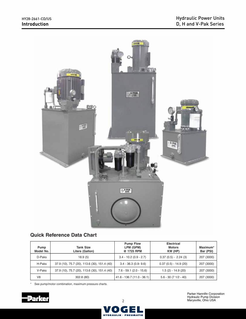
V8 302.8 (80) 41.6 - 136.7 (11.0 - 36.1) 5.6 - 30 (7 1/2 - 40) 207 (3000)
* See pump/motor combination, maximum pressure charts.
skaP-V ,H ,D seireSnoitcudortnI
Quick Reference Data Chart
Pump Flow Electrical MPLeziS knaTpmuP (GPM) Motors Maximum*
Model No. Liters (Gallon) @ 1725 RPM KW (HP) Bar (PSI)
2.01 - 4.3)5( 9.81skaP-D (0.9 - 2.7) 0.37 (0.5) - 2.24 (3) 207 (3000)
H-Paks 37.9 (10), 75.7 (20), 113.6 (30), 151.4 (40) 3.4 - 36.3 (0.9- 9.6) 0.37 (0.5) - 14.9 (20) 207 (3000)
V-Paks 37.9 (10), 75.7 (20), 113.6 (30), 151.4 (40) 7.6 - 59.1 (2.0 - 15.6) 1.5 (2) - 14.9 (20) 207 (3000)
IntroductionHydraulic Power UnitsD, H and V-Pak Series
2 3
Parker Hannifin CorporationHydraulic Pump DivisionMarysville, Ohio USA
HY28-2661-CD/USCatalog HY28-2661-CD/US
Volume ControlVertical Power Units
Parker Hannifin CorporationHydraulic Pump DivisionMaryville, Ohio USA
3
Technical Information Series D, H, V-Paks
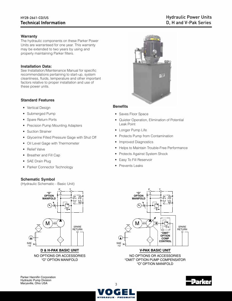
Standard Features
• Vertical Design
• Submerged Pump
• Spare Return Ports
• Precision Pump Mounting Adapters
• Suction Strainer
• Glycerine Filled Pressure Gage with Shut Off
• Oil Level Gage with Thermometer
• Relief Valve
• Breather and Fill Cap
• SAE Drain Plug
• Parker Connector Technology
WarrantyThe hydraulic components on these Parker PowerUnits are warranteed for one year. This warrantymay be extended to two years by using andproperly maintaining Parker filters.
Installation Data:See Installation/Maintenance Manual for specificrecommendations pertaining to start-up, systemcleanliness, fluids, temperature and other importantfactors relative to proper installation and use ofthese power units.
Schematic Symbol(Hydraulic Schematic - Basic Unit)
Benefits
• Saves Floor Space
• Quieter Operation, Elimination of PotentialLeak Point
• Longer Pump Life
• Protects Pump from Contamination
• Improved Diagnostics
• Helps to Maintain Trouble-Free Performance
• Protects Against System Shock
• Easy To Fill Reservoir
• Prevents Leaks
SPARERETURN
SAE-12
M
X
“O”OPTION
MANIFOLD
“OMIT”OPTIONCOMP
CONTROL
V-PAK BASIC UNIT—————————
NO OPTIONS OR ACCESSORIES“OMIT” OPTION PUMP COMPENSATOR
“O” OPTION MANIFOLD
P
P
T
A
B
T
X
X
X
SPARERETURN
SAE-12
M
X
“O”OPTION
MANIFOLD
D & H-PAK BASIC UNIT———————————
NO OPTIONS OR ACCESSORIES“O” OPTION MANIFOLD
P
P
T
A
B
T
X
X
X
Technical InformationHydraulic Power UnitsD, H and V-Pak Series
4
Parker Hannifin CorporationHydraulic Pump DivisionMarysville, Ohio USA
HY28-2661-CD/US
5
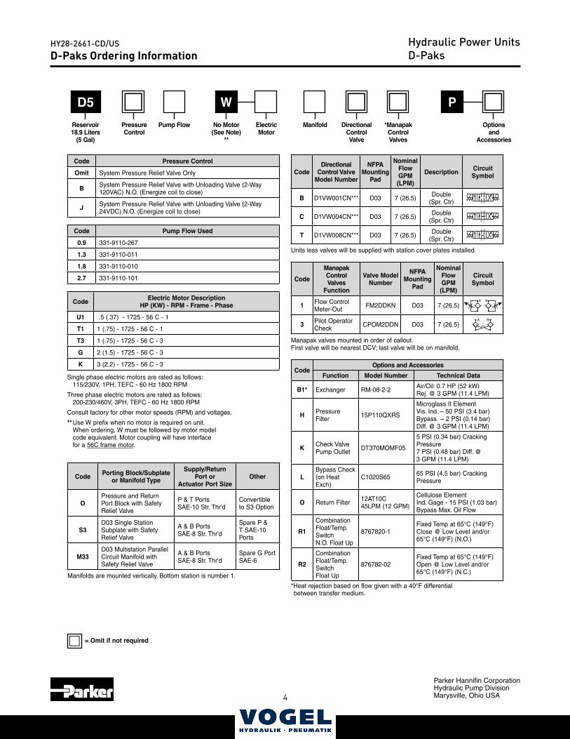
D-Paks Ordering InformationHydraulic Power UnitsD-Paks
Code Electric Motor DescriptionHP (KW) - RPM - Frame - Phase
U1 .5 (.37) - 1725 - 56 C - 1
T1 1 (.75) - 1725 - 56 C - 1
T3 1 (.75) - 1725 - 56 C - 3
G 2 (1.5) - 1725 - 56 C - 3
K 3 (2.2) - 1725 - 56 C - 3
Single phase electric motors are rated as follows: 115/230V, 1PH, TEFC - 60 Hz 1800 RPM
Three phase electric motors are rated as follows: 200-230/460V, 3PH, TEFC - 60 Hz 1800 RPM
Consult factory for other motor speeds (RPM) and voltages.
** Use W prefix when no motor is required on unit. When ordering, W must be followed by motor model code equivalent. Motor coupling will have interface for a 56C frame motor.
WD5
Code Pump Flow Used
0.9 331-9110-267
1.3 331-9110-011
1.8 331-9110-010
2.7 331-9110-101
P
Reservoir18.9 Liters
(5 Gal)
No Motor (See Note)
**
Code Pressure Control
Omit System Pressure Relief Valve Only
B System Pressure Relief Valve with Unloading Valve (2-Way 120VAC) N.O. (Energize coil to close)
J System Pressure Relief Valve with Unloading Valve (2-Way 24VDC) N.O. (Energize coil to close)
Code Porting Block/Subplate or Manifold Type
Supply/Return Port or
Actuator Port SizeOther
OPressure and Return Port Block with Safety Relief Valve
P & T PortsSAE-10 Str. Thr'd
Convertible to S3 Option
S3D03 Single Station Subplate with Safety Relief Valve
A & B PortsSAE-8 Str. Thr'd
Spare P & T SAE-10 Ports
M33D03 Multistation Parallel Circuit Manifold with Safety Relief Valve
A & B PortsSAE-8 Str. Thr'd
Spare G Port SAE-6
Manifolds are mounted vertically. Bottom station is number 1.
Code
ManapakControlValves
Function
Valve Model Number
NFPA Mounting
Pad
Nominal Flow GPM (LPM)
Circuit Symbol
1 Flow Control Meter-Out FM2DDKN D03 7 (26.5)
A B
3 Pilot Operator Check CPOM2DDN D03 7 (26.5)
A B
Manapak valves mounted in order of callout. First valve will be nearest DCV; last valve will be on manifold.
CodeOptions and Accessories
Function Model Number Technical Data
B1* Exchanger RM-08-2-2 Air/Oil: 0.7 HP (52 kW) Rej. @ 3 GPM (11.4 LPM)
H Pressure Filter 15P110QXRS
Microglass II ElementVis. Ind. – 50 PSI (3.4 bar)Bypass – 2 PSI (0.14 bar)Diff. @ 3 GPM (11.4 LPM)
K Check ValvePump Outlet DT370MOMF05
5 PSI (0.34 bar) Cracking Pressure7 PSI (0.48 bar) Diff. @ 3 GPM (11.4 LPM)
LBypass Check(on Heat Exch)
C1020S65 65 PSI (4.5 bar) Cracking Pressure
O Return Filter 12AT10C 45LPM (12 GPM)
Cellulose ElementInd. Gage - 15 PSI (1.03 bar)Bypass Max. Oil Flow
R1
CombinationFloat/Temp. SwitchN.O. Float Up
8767820-1Fixed Temp at 65°C (149°F)Close @ Low Level and/or65°C (149°F) (N.O.)
R2
Combination Float/Temp. SwitchFloat Up
876782-02Fixed Temp at 65°C (149°F)Open @ Low Level and/or65°C (149°F) (N.C.)
*Heat rejection based on flow given with a 40°F differential between transfer medium.
CodeDirectional
Control Valve Model Number
NFPA Mounting
Pad
Nominal Flow GPM (LPM)
Description Circuit Symbol
B D1VW001CN*** D03 7 (26.5) Double (Spr. Ctr)
A B
P T
���
�
C D1VW004CN*** D03 7 (26.5) Double (Spr. Ctr)
A B
P T
���
�
T D1VW008CN*** D03 7 (26.5) Double (Spr. Ctr)
A B
P T
���
�
Units less valves will be supplied with station cover plates installed.
= Omit if not required
Pressure Control
Pump Flow ElectricMotor
Manifold DirectionalControl Valve
*ManapakControlValves
Optionsand
Accessories

4 5
Parker Hannifin CorporationHydraulic Pump DivisionMarysville, Ohio USA
HY28-2661-CD/US
NotesHydraulic Power Units
CodeOptions and Accessories
Function Model Number Technical Data
B1* Exchanger RM-08-2-2 Air/Oil: 0.7 HP (52 kW) Rej. @ 3 GPM (11.4 LPM)
H Pressure Filter 15P110QXRS
Microglass II ElementVis. Ind. – 50 PSI (3.4 bar)Bypass – 2 PSI (0.14 bar)Diff. @ 3 GPM (11.4 LPM)
K Check ValvePump Outlet DT370MOMF05
5 PSI (0.34 bar) Cracking Pressure7 PSI (0.48 bar) Diff. @ 3 GPM (11.4 LPM)
LBypass Check(on Heat Exch)
C1020S65 65 PSI (4.5 bar) Cracking Pressure
O Return Filter 12AT10C 45LPM (12 GPM)
Cellulose ElementInd. Gage - 15 PSI (1.03 bar)Bypass Max. Oil Flow
R1
CombinationFloat/Temp. SwitchN.O. Float Up
8767820-1Fixed Temp at 65°C (149°F)Close @ Low Level and/or65°C (149°F) (N.O.)
R2
Combination Float/Temp. SwitchFloat Up
876782-02Fixed Temp at 65°C (149°F)Open @ Low Level and/or65°C (149°F) (N.C.)
6
Parker Hannifin CorporationHydraulic Pump DivisionMarysville, Ohio USA
HY28-2661-CD/US
7
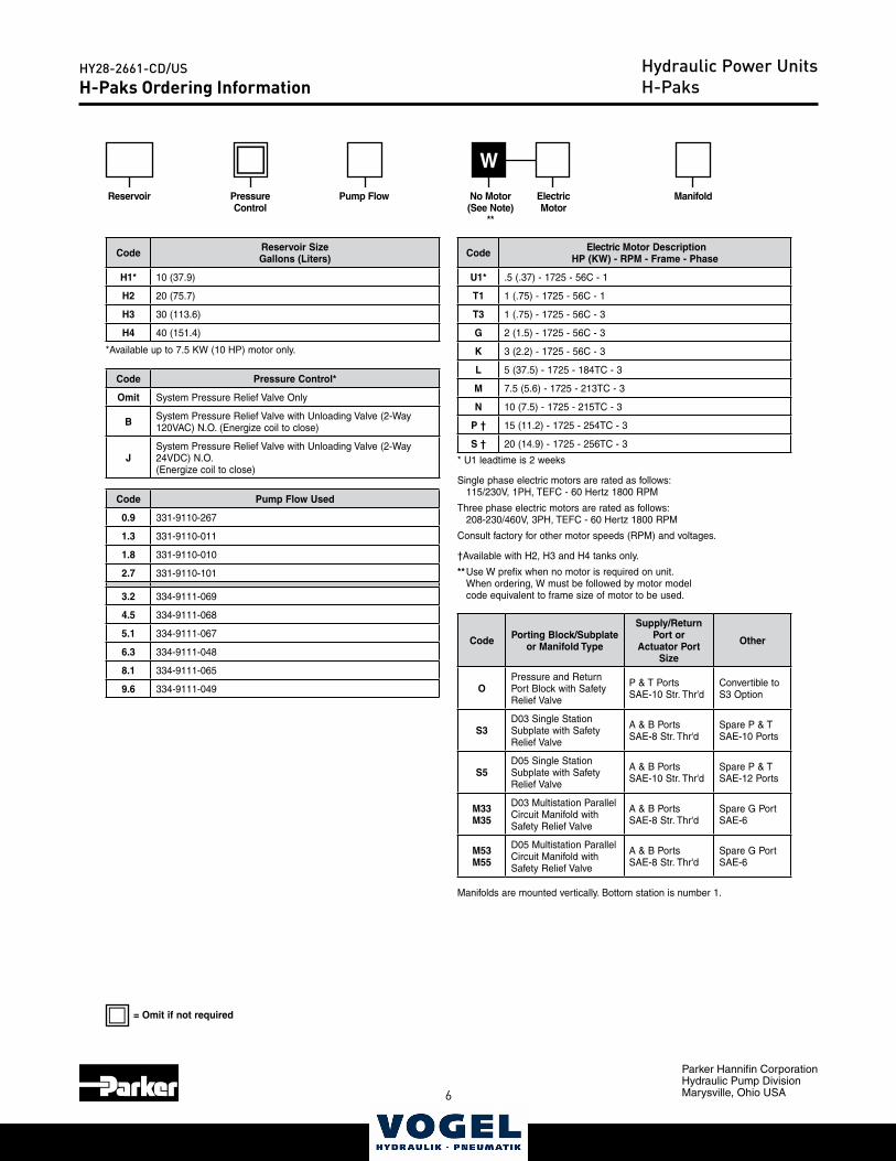
H-Paks Ordering InformationHydraulic Power UnitsH-Paks
Code Electric Motor DescriptionHP (KW) - RPM - Frame - Phase
U1* .5 (.37) - 1725 - 56C - 1
T1 1 (.75) - 1725 - 56C - 1
T3 1 (.75) - 1725 - 56C - 3
G 2 (1.5) - 1725 - 56C - 3
K 3 (2.2) - 1725 - 56C - 3
L 5 (37.5) - 1725 - 184TC - 3
M 7.5 (5.6) - 1725 - 213TC - 3
N 10 (7.5) - 1725 - 215TC - 3
P † 15 (11.2) - 1725 - 254TC - 3
S † 20 (14.9) - 1725 - 256TC - 3
* U1 leadtime is 2 weeks
Single phase electric motors are rated as follows: 115/230V, 1PH, TEFC - 60 Hertz 1800 RPM
Three phase electric motors are rated as follows: 208-230/460V, 3PH, TEFC - 60 Hertz 1800 RPM
Consult factory for other motor speeds (RPM) and voltages.
†Available with H2, H3 and H4 tanks only.
** Use W prefix when no motor is required on unit. When ordering, W must be followed by motor model code equivalent to frame size of motor to be used.
W
Code Pump Flow Used
0.9 331-9110-267
1.3 331-9110-011
1.8 331-9110-010
2.7 331-9110-101
3.2 334-9111-069
4.5 334-9111-068
5.1 334-9111-067
6.3 334-9111-048
8.1 334-9111-065
9.6 334-9111-049
Code Reservoir SizeGallons (Liters)
H1* 10 (37.9)
H2 20 (75.7)
H3 30 (113.6)
H4 40 (151.4)
Reservoir No Motor (See Note)
**
Code Pressure Control*
Omit System Pressure Relief Valve Only
B System Pressure Relief Valve with Unloading Valve (2-Way 120VAC) N.O. (Energize coil to close)
JSystem Pressure Relief Valve with Unloading Valve (2-Way 24VDC) N.O.(Energize coil to close)
Code Porting Block/Subplate or Manifold Type
Supply/Return Port or
Actuator Port Size
Other
OPressure and Return Port Block with Safety Relief Valve
P & T PortsSAE-10 Str. Thr'd
Convertible to S3 Option
S3D03 Single Station Subplate with Safety Relief Valve
A & B PortsSAE-8 Str. Thr'd
Spare P & T SAE-10 Ports
S5D05 Single Station Subplate with Safety Relief Valve
A & B PortsSAE-10 Str. Thr'd
Spare P & T SAE-12 Ports
M33M35
D03 Multistation Parallel Circuit Manifold with Safety Relief Valve
A & B PortsSAE-8 Str. Thr'd
Spare G Port SAE-6
M53M55
D05 Multistation Parallel Circuit Manifold with Safety Relief Valve
A & B PortsSAE-8 Str. Thr'd
Spare G Port SAE-6
Manifolds are mounted vertically. Bottom station is number 1.
Pressure Control
Pump Flow ElectricMotor
Manifold
*Available up to 7.5 KW (10 HP) motor only.
= Omit if not required
6 7
Parker Hannifin CorporationHydraulic Pump DivisionMarysville, Ohio USA
HY28-2661-CD/US
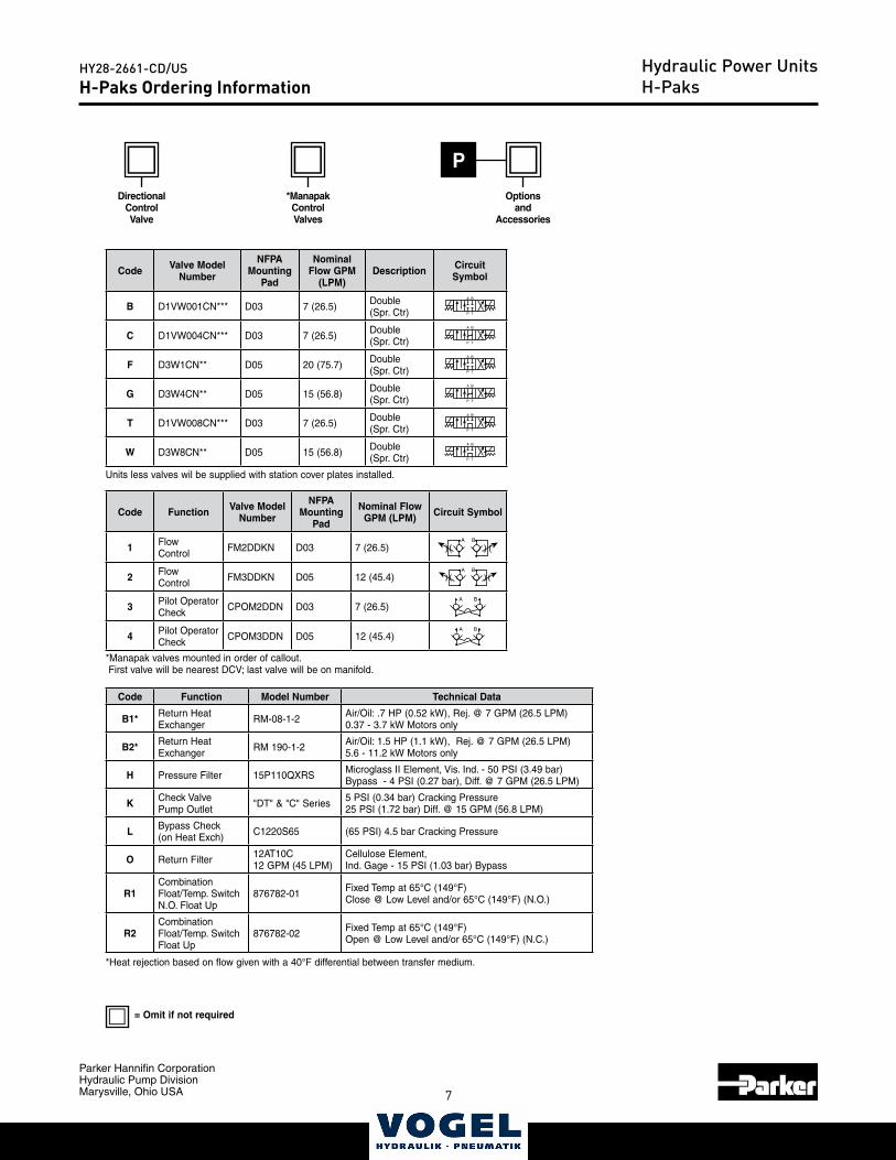
H-Paks Ordering InformationHydraulic Power UnitsH-Paks
P
Code Function Valve Model Number
NFPA Mounting
Pad
Nominal Flow GPM (LPM) Circuit Symbol
1 Flow Control FM2DDKN D03 7 (26.5)
A B
2 Flow Control FM3DDKN D05 12 (45.4)
A B
3 Pilot Operator Check CPOM2DDN D03 7 (26.5)
A B
4 Pilot Operator Check CPOM3DDN D05 12 (45.4)
A B
*Manapak valves mounted in order of callout. First valve will be nearest DCV; last valve will be on manifold.
Code Function Model Number Technical Data
B1* Return Heat Exchanger RM-08-1-2 Air/Oil: .7 HP (0.52 kW), Rej. @ 7 GPM (26.5 LPM)
0.37 - 3.7 kW Motors only
B2* Return Heat Exchanger RM 190-1-2 Air/Oil: 1.5 HP (1.1 kW), Rej. @ 7 GPM (26.5 LPM)
5.6 - 11.2 kW Motors only
H Pressure Filter 15P110QXRS Microglass II Element, Vis. Ind. - 50 PSI (3.49 bar)Bypass - 4 PSI (0.27 bar), Diff. @ 7 GPM (26.5 LPM)
K Check ValvePump Outlet "DT" & "C" Series 5 PSI (0.34 bar) Cracking Pressure
25 PSI (1.72 bar) Diff. @ 15 GPM (56.8 LPM)
L Bypass Check(on Heat Exch) C1220S65 (65 PSI) 4.5 bar Cracking Pressure
O Return Filter 12AT10C 12 GPM (45 LPM)
Cellulose Element, Ind. Gage - 15 PSI (1.03 bar) Bypass
R1CombinationFloat/Temp. SwitchN.O. Float Up
876782-01 Fixed Temp at 65°C (149°F)Close @ Low Level and/or 65°C (149°F) (N.O.)
R2Combination Float/Temp. SwitchFloat Up
876782-02 Fixed Temp at 65°C (149°F)Open @ Low Level and/or 65°C (149°F) (N.C.)
*Heat rejection based on flow given with a 40°F differential between transfer medium.
Code Valve Model Number
NFPA Mounting
Pad
Nominal Flow GPM
(LPM)Description Circuit
Symbol
B D1VW001CN*** D03 7 (26.5) Double (Spr. Ctr)
A B
P T
���
�
C D1VW004CN*** D03 7 (26.5) Double (Spr. Ctr)
A B
P T
���
�
F D3W1CN** D05 20 (75.7) Double (Spr. Ctr)
A B
P T
���
�
G D3W4CN** D05 15 (56.8) Double (Spr. Ctr)
A B
P T
���
�
T D1VW008CN*** D03 7 (26.5) Double (Spr. Ctr)
A B
P T
���
�
W D3W8CN** D05 15 (56.8) Double (Spr. Ctr)
A B
P T
���
�
Units less valves wil be supplied with station cover plates installed.
DirectionalControl Valve
*ManapakControlValves
Optionsand
Accessories
= Omit if not required
8
Parker Hannifin CorporationHydraulic Pump DivisionMarysville, Ohio USA
HY28-2661-CD/US
9
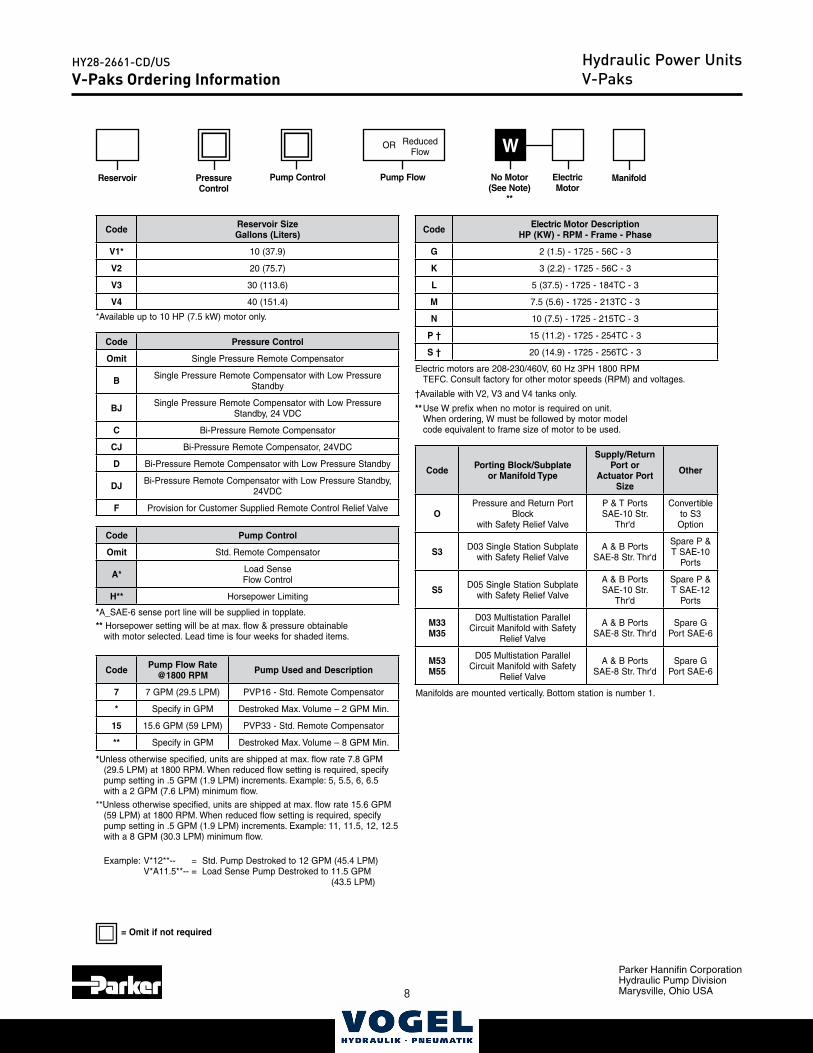
V-Paks Ordering InformationHydraulic Power UnitsV-Paks
Code Electric Motor DescriptionHP (KW) - RPM - Frame - Phase
G 2 (1.5) - 1725 - 56C - 3
K 3 (2.2) - 1725 - 56C - 3
L 5 (37.5) - 1725 - 184TC - 3
M 7.5 (5.6) - 1725 - 213TC - 3
N 10 (7.5) - 1725 - 215TC - 3
P † 15 (11.2) - 1725 - 254TC - 3
S † 20 (14.9) - 1725 - 256TC - 3
Electric motors are 208-230/460V, 60 Hz 3PH 1800 RPM TEFC. Consult factory for other motor speeds (RPM) and voltages.
†Available with V2, V3 and V4 tanks only.
** Use W prefix when no motor is required on unit. When ordering, W must be followed by motor model code equivalent to frame size of motor to be used.
W
Code Reservoir SizeGallons (Liters)
V1* 10 (37.9)
V2 20 (75.7)
V3 30 (113.6)
V4 40 (151.4)
No Motor (See Note)
**
Code Pressure Control
Omit Single Pressure Remote Compensator
B Single Pressure Remote Compensator with Low Pressure Standby
BJ Single Pressure Remote Compensator with Low Pressure Standby, 24 VDC
C Bi-Pressure Remote Compensator
CJ Bi-Pressure Remote Compensator, 24VDC
D Bi-Pressure Remote Compensator with Low Pressure Standby
DJ Bi-Pressure Remote Compensator with Low Pressure Standby, 24VDC
F Provision for Customer Supplied Remote Control Relief Valve
Code Porting Block/Subplate or Manifold Type
Supply/Return Port or
Actuator Port Size
Other
OPressure and Return Port
Block with Safety Relief Valve
P & T PortsSAE-10 Str.
Thr'd
Convertible to S3
Option
S3 D03 Single Station Subplate with Safety Relief Valve
A & B PortsSAE-8 Str. Thr'd
Spare P & T SAE-10
Ports
S5 D05 Single Station Subplate with Safety Relief Valve
A & B PortsSAE-10 Str.
Thr'd
Spare P & T SAE-12
Ports
M33M35
D03 Multistation Parallel Circuit Manifold with Safety
Relief Valve
A & B PortsSAE-8 Str. Thr'd
Spare G Port SAE-6
M53M55
D05 Multistation Parallel Circuit Manifold with Safety
Relief Valve
A & B PortsSAE-8 Str. Thr'd
Spare G Port SAE-6
Manifolds are mounted vertically. Bottom station is number 1.
Pressure Control
Pump Control ElectricMotor
Manifold
*Available up to 10 HP (7.5 kW) motor only.
*A_SAE-6 sense port line will be supplied in topplate.
** Horsepower setting will be at max. flow & pressure obtainablewith motor selected. Lead time is four weeks for shaded items.
Code Pump Control
Omit Std. Remote Compensator
A* Load Sense Flow Control
H** Horsepower Limiting
Pump Flow
Reduced Flow
OR
Code Pump Flow Rate @1800 RPM Pump Used and Description
7 7 GPM (29.5 LPM) PVP16 - Std. Remote Compensator
* Specify in GPM Destroked Max. Volume – 2 GPM Min.
15 15.6 GPM (59 LPM) PVP33 - Std. Remote Compensator
** Specify in GPM Destroked Max. Volume – 8 GPM Min.
*Unless otherwise specified, units are shipped at max. flow rate 7.8 GPM (29.5 LPM) at 1800 RPM. When reduced flow setting is required, specify pump setting in .5 GPM (1.9 LPM) increments. Example: 5, 5.5, 6, 6.5 with a 2 GPM (7.6 LPM) minimum flow.
**Unless otherwise specified, units are shipped at max. flow rate 15.6 GPM (59 LPM) at 1800 RPM. When reduced flow setting is required, specify pump setting in .5 GPM (1.9 LPM) increments. Example: 11, 11.5, 12, 12.5 with a 8 GPM (30.3 LPM) minimum flow.
Example: V*12**-- = Std. Pump Destroked to 12 GPM (45.4 LPM) V*A11.5**-- = Load Sense Pump Destroked to 11.5 GPM
(43.5 LPM)
= Omit if not required
Reservoir
8 9
Parker Hannifin CorporationHydraulic Pump DivisionMarysville, Ohio USA
HY28-2661-CD/US
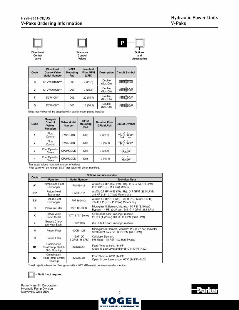
V-Paks Ordering InformationHydraulic Power UnitsV-Paks
P
Code
Manapak ControlValves
Function
Valve Model Number
NFPA Mounting
Pad
Nominal Flow GPM (LPM) Circuit Symbol
1 Flow Control FM2DDKN D03 7 (26.5)
A B
2 Flow Control FM3DDKN D05 12 (45.4)
A B
3 Pilot Operator Check CPOM2DDN D03 7 (26.5)
A B
4 Pilot Operator Check CPOM3DDN D05 12 (45.4)
A B
*Manapak valves mounted in order of callout. First valve will be nearest DCV; last valve will be on manifold.
CodeOptions and Accessories
Function Model Number Technical Data
A* Pump Case Heat Exchanger RM-08-4-2 Air/Oil: 0.7 HP (0.52 kW), Rej. @ .5 GPM (1.9 LPM)
2-15 HP (1.5 - 11.2 kW) Motors
B1* Return Heat Exchanger RM-08-1-2 Air/Oil: 0.7 HP (0.52 kW), Rej. @ 7 GPM (26.5 LPM)
2-5 HP (1.5 - 3.7 kW) Motors only
B2* Return Heat Exchanger RM 190-1-2 Air/Oil: 1.5 HP (1.1 kW), Rej. @ 7 GPM (26.5 LPM)
7.5-15 HP (5.6 - 11.2 kW) Motors only
H Pressure Filter 15P110QXRS Microglass II Element, Vis. Ind. - 50 PSI (3.49 bar)Bypass - 4 PSI (0.27 bar), Diff. @ 7 GPM (26.5 LPM)
K Check ValvePump Outlet "DT" & "C" Series 5 PSI (0.34 bar) Cracking Pressure
25 PSI (1.72 bar) Diff. @ 15 GPM (56.8 LPM)
L Bypass Check(on Heat Exch) C1220S65 (65 PSI) 4.5 bar Cracking Pressure
N Return Filter 40CN110B Microglass II Element, Visual 25 PSI (1.72 bar) Indicator 3 PSI (0.21 bar) Diff. @ 7 GPM (26.5 LPM)
O Return Filter 12AT10C 12 GPM (45 LPM)
Cellulose Element, Ind. Gage - 15 PSI (1.03 bar) Bypass
R1Combination
Float/Temp. SwitchN.O. Float Up
876782-01 Fixed Temp at 65°C (149°F)Close @ Low Level and/or 65°C (149°F) (N.O.)
R2Combination
Float/Temp. SwitchFloat Up
876782-02 Fixed Temp at 65°C (149°F)Open @ Low Level and/or 65°C (149°F) (N.C.)
*Heat rejection based on flow given with a 40°F differential between transfer medium.
CodeDirectional
Control Valve Model Number
NFPA Mounting
Pad
Nominal Flow GPM
(LPM)Description Circuit Symbol
B D1VW001CN*** D03 7 (26.5) Double (Spr. Ctr)
A B
P T
���
�
C D1VW004CN*** D03 7 (26.5) Double (Spr. Ctr)
A B
P T
���
�
F D3W1CN** D05 20 (75.7) Double (Spr. Ctr)
A B
P T
���
�
G D3W4CN** D05 15 (56.8) Double (Spr. Ctr)
A B
P T
���
�
Units less valves wil be supplied with station cover plates installed.
DirectionalControl Valve
*ManapakControlValves
Optionsand
Accessories
= Omit if not required
10
Parker Hannifin CorporationHydraulic Pump DivisionMarysville, Ohio USA
HY28-2661-CD/US
11
Catalog HY28-2661-CD/USVolume ControlVertical Power Units
Parker Hannifin CorporationHydraulic Pump DivisionMaryville, Ohio USA
13
263.1(10.36)
“A” *
317.5 (12.5)342.9 (13.5)
381.0 (15.0)
317.5 (12.5)
254.0(10.0)
3.1(.12)307.9
(12.12)
31.8(1.25)
19.1(.75)
22.9(.9)
38.1(1.5)
B A
B A
G
“M3*” & "C3*" OPTION MANIFOLD(MULTI-STATION D03 MANIFOLD)
SHOWN WITH OPTION “O” RETURN FILTER
SPARE RETURN PORT1/2" NPTFWITH DROP PIPE
P
T
SPARE RETURN PORT1/2" NPTFWITH DROP PIPE
“O” & “S3” OPTION MANIFOLD(P & T BLOCK & D03 SINGLE STATION)
SHOWN WITH OPTION “O” RETURN FILTER
“O” & “S3” OPTION MANIFOLD(P & T BLOCK & D03 SINGLE STATION)
BASIC UNIT
B A
T
P
T
TANK DRAINSAE-12 (PLUGGED)
OIL LEVELSIGHT GAGE
FILLERBREATHER
“O” (“P” & “T” BLOCK)OR “S3” (“D03” SUBPLATE)SHOWN-SEE MANIFOLD OPTIONS
ELECTRIC MOTOR
SPARE RETURN PORT1/2" NPTF WITHDROP PIPE
.56 DIA. MOUNTINGHOLES - 4 PLACES
PRESSURE GAGEWITH NEEDLE VALVE
SYSTEM RELIEF VALVE
B A
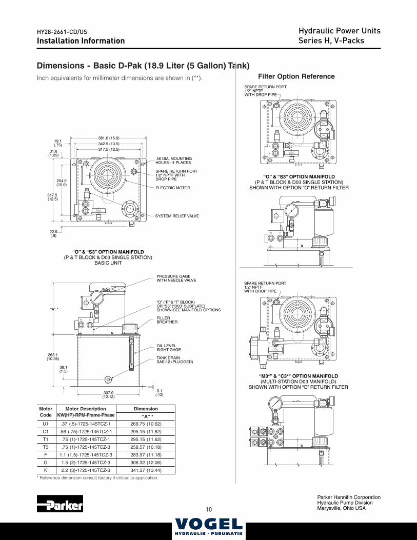
Installation Information Series D-Paks
Dimensions - Basic D-Pak (18.9 Liter (5 Gallon) Tank)Inch equivalents for millimeter dimensions are shown in (**).
* Reference dimension consult factory if critical to application.
Motor Motor Description DimensionCode KW(HP)-RPM-Frame-Phase “A” *
U1 .37 (.5)-1725-145TCZ-1 269.75 (10.62)
C1 .56 (.75)-1725-145TCZ-1 295.15 (11.62)
T1 .75 (1)-1725-145TCZ-1 295.15 (11.62)
T3 .75 (1)-1725-145TCZ-3 258.57 (10.18)
F 1.1 (1.5)-1725-145TCZ-3 283.97 (11.18)
G 1.5 (2)-1725-145TCZ-3 306.32 (12.06)
K 2.2 (3)-1725-145TCZ-3 341.37 (13.44)
Filter Option Reference
Installation InformationHydraulic Power UnitsSeries H, V-Packs
10 11
Parker Hannifin CorporationHydraulic Pump DivisionMarysville, Ohio USA
HY28-2661-CD/USCatalog HY28-2661-CD/US
Volume ControlVertical Power Units
Parker Hannifin CorporationHydraulic Pump DivisionMaryville, Ohio USA
14
“M5*” OPTION MANIFOLD(MULTI-STATION D05 MANIFOLD)
SHOWN WITH OPTION “O” RETURN FILTER
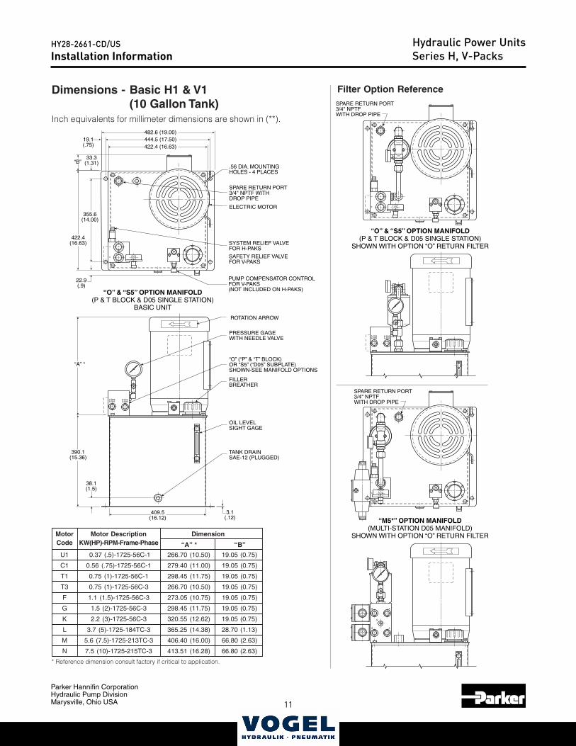
355.6(14.00)
422.4(16.63)
444.5 (17.50)422.4 (16.63)
482.6 (19.00)
“B”33.3
(1.31)
19.1(.75)
22.9(.9)
PT
PT
PT
SPARE RETURN PORT3/4" NPTFWITH DROP PIPE
SPARE RETURN PORT3/4" NPTFWITH DROP PIPE
A
AB
B
G
A-D03B-D05
B-D03A-D05
A-D03B-D05
B-D03A-D05
“O” & “S5” OPTION MANIFOLD(P & T BLOCK & D05 SINGLE STATION)
SHOWN WITH OPTION “O” RETURN FILTER
TANK DRAINSAE-12 (PLUGGED)
OIL LEVELSIGHT GAGE
FILLERBREATHER
“O” (“P” & “T” BLOCK)OR “S5” (“D05” SUBPLATE)SHOWN-SEE MANIFOLD OPTIONS
ELECTRIC MOTOR
SPARE RETURN PORT3/4" NPTF WITHDROP PIPE
.56 DIA. MOUNTINGHOLES - 4 PLACES
“O” & “S5” OPTION MANIFOLD(P & T BLOCK & D05 SINGLE STATION)
BASIC UNIT
PRESSURE GAGEWITH NEEDLE VALVE
PUMP COMPENSATOR CONTROLFOR V-PAKS(NOT INCLUDED ON H-PAKS)
ROTATION ARROW
SYSTEM RELIEF VALVEFOR H-PAKS
SAFETY RELIEF VALVEFOR V-PAKS
3.1(.12)
409.5(16.12)
38.1(1.5)
“A” *
390.1(15.36)
Motor Motor Description DimensionCode KW(HP)-RPM-Frame-Phase “A” * “B”
U1 0.37 (.5)-1725-56C-1 266.70 (10.50) 19.05 (0.75)
C1 0.56 (.75)-1725-56C-1 279.40 (11.00) 19.05 (0.75)
T1 0.75 (1)-1725-56C-1 298.45 (11.75) 19.05 (0.75)
T3 0.75 (1)-1725-56C-3 266.70 (10.50) 19.05 (0.75)
F 1.1 (1.5)-1725-56C-3 273.05 (10.75) 19.05 (0.75)
G 1.5 (2)-1725-56C-3 298.45 (11.75) 19.05 (0.75)
K 2.2 (3)-1725-56C-3 320.55 (12.62) 19.05 (0.75)
L 3.7 (5)-1725-184TC-3 365.25 (14.38) 28.70 (1.13)
M 5.6 (7.5)-1725-213TC-3 406.40 (16.00) 66.80 (2.63)
N 7.5 (10)-1725-215TC-3 413.51 (16.28) 66.80 (2.63)
Installation Information Series H, V-Paks
Dimensions - Basic H1 & V1(10 Gallon Tank)
Inch equivalents for millimeter dimensions are shown in (**).
Filter Option Reference
* Reference dimension consult factory if critical to application.
Installation InformationHydraulic Power UnitsSeries H, V-Packs
12
Parker Hannifin CorporationHydraulic Pump DivisionMarysville, Ohio USA
HY28-2661-CD/US
13
Catalog HY28-2661-CD/USVolume ControlVertical Power Units
Parker Hannifin CorporationHydraulic Pump DivisionMaryville, Ohio USA
15
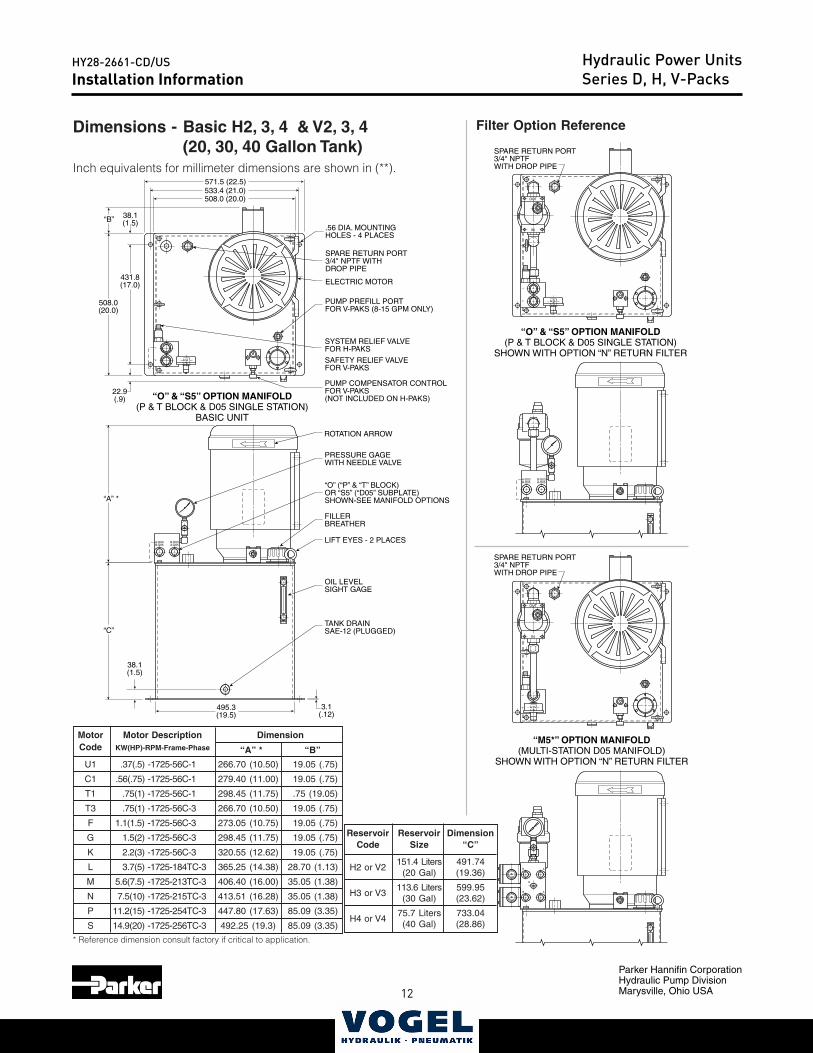
TANK DRAINSAE-12 (PLUGGED)
OIL LEVELSIGHT GAGE
FILLERBREATHER
“O” (“P” & “T” BLOCK)OR “S5” (“D05” SUBPLATE)SHOWN-SEE MANIFOLD OPTIONS
ELECTRIC MOTOR
SPARE RETURN PORT3/4" NPTF WITHDROP PIPE
.56 DIA. MOUNTINGHOLES - 4 PLACES
SYSTEM RELIEF VALVEFOR H-PAKS
SAFETY RELIEF VALVEFOR V-PAKS
PUMP PREFILL PORTFOR V-PAKS (8-15 GPM ONLY)
“M5*” OPTION MANIFOLD(MULTI-STATION D05 MANIFOLD)
SHOWN WITH OPTION “N” RETURN FILTER
“O” & “S5” OPTION MANIFOLD(P & T BLOCK & D05 SINGLE STATION)
SHOWN WITH OPTION “N” RETURN FILTER
“O” & “S5” OPTION MANIFOLD(P & T BLOCK & D05 SINGLE STATION)
BASIC UNIT
SPARE RETURN PORT3/4" NPTFWITH DROP PIPE
LIFT EYES - 2 PLACES
PRESSURE GAGEWITH NEEDLE VALVE
PUMP COMPENSATOR CONTROLFOR V-PAKS(NOT INCLUDED ON H-PAKS)
ROTATION ARROW
22.9(.9)
508.0(20.0)
431.8(17.0)
38.1(1.5)“B”
571.5 (22.5)533.4 (21.0)508.0 (20.0)
3.1(.12)
495.3(19.5)
38.1(1.5)
“A” *
SPARE RETURN PORT3/4" NPTFWITH DROP PIPE
“C”
PT
IN
OUT
A
AB
B
G
A-D03B-D05
B-D03A-D05
A-D03B-D05
B-D03A-D05
PT
IN
OUT
PT
Installation Information Series H, V-Paks
Dimensions - Basic H2, 3, 4 & V2, 3, 4(20, 30, 40 Gallon Tank)
Inch equivalents for millimeter dimensions are shown in (**).
Motor Motor Description DimensionCode KW(HP)-RPM-Frame-Phase “A” * “B”
U1 .37(.5) -1725-56C-1 266.70 (10.50) 19.05 (.75)
C1 .56(.75) -1725-56C-1 279.40 (11.00) 19.05 (.75)
T1 .75(1) -1725-56C-1 298.45 (11.75) .75 (19.05)
T3 .75(1) -1725-56C-3 266.70 (10.50) 19.05 (.75)
F 1.1(1.5) -1725-56C-3 273.05 (10.75) 19.05 (.75)
G 1.5(2) -1725-56C-3 298.45 (11.75) 19.05 (.75)
K 2.2(3) -1725-56C-3 320.55 (12.62) 19.05 (.75)
L 3.7(5) -1725-184TC-3 365.25 (14.38) 28.70 (1.13)
M 5.6(7.5) -1725-213TC-3 406.40 (16.00) 35.05 (1.38)
N 7.5(10) -1725-215TC-3 413.51 (16.28) 35.05 (1.38)
P 11.2(15) -1725-254TC-3 447.80 (17.63) 85.09 (3.35)
S 14.9(20) -1725-256TC-3 492.25 (19.3) 85.09 (3.35)
Filter Option Reference
Reservoir Reservoir DimensionCode Size “C”
H2 or V2151.4 Liters 491.74
(20 Gal) (19.36)
H3 or V3113.6 Liters 599.95
(30 Gal) (23.62)
H4 or V475.7 Liters 733.04(40 Gal) (28.86)
* Reference dimension consult factory if critical to application.
Installation InformationHydraulic Power UnitsSeries D, H, V-Packs
12 13
Parker Hannifin CorporationHydraulic Pump DivisionMarysville, Ohio USA
HY28-2661-CD/USCatalog HY28-2661-CD/US
Volume ControlVertical Power Units
Parker Hannifin CorporationHydraulic Pump DivisionMaryville, Ohio USA
16
A-D03B-D05
B-D03A-D05
PT
X X
A-D03B-D05
B-D03A-D05
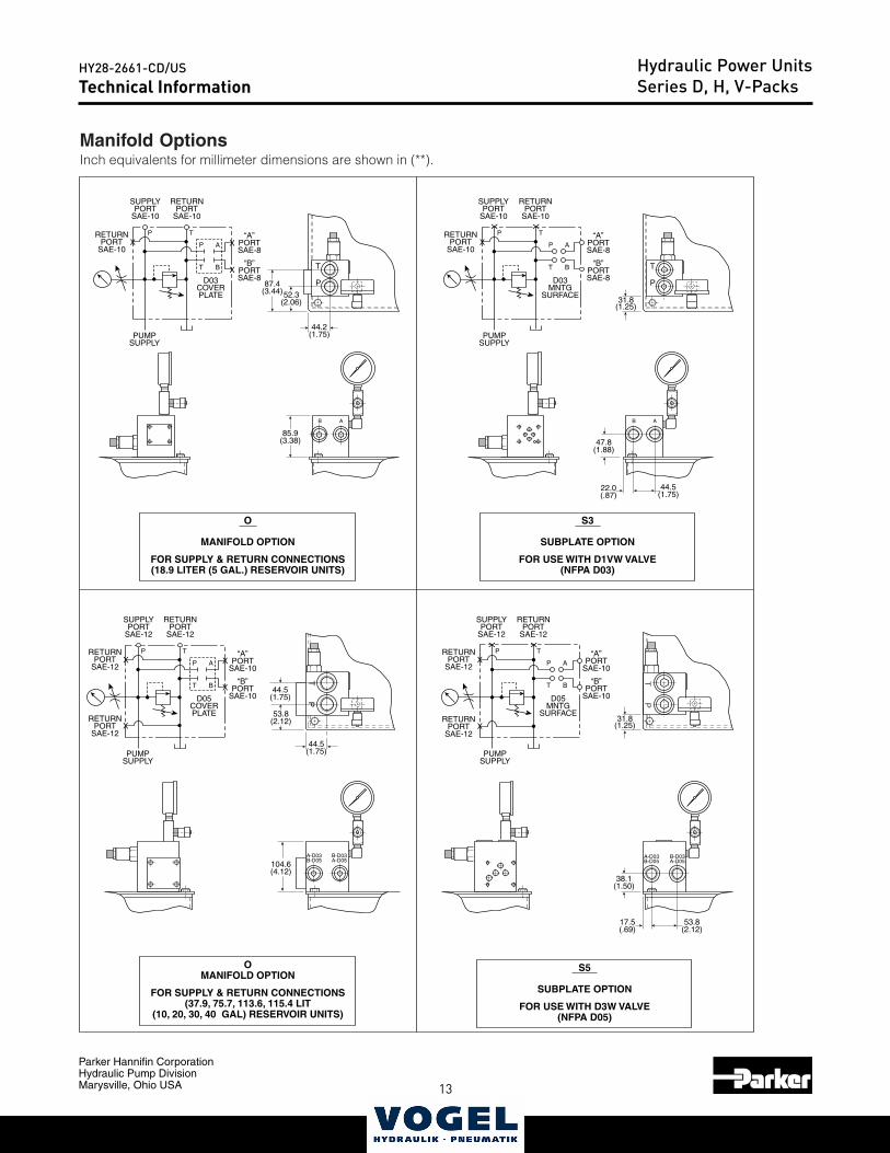
SUPPLYPORT
SAE-10
P
PUMPSUPPLY
T
A
B
RETURNPORT
SAE-10
RETURNPORT
SAE-10
D03COVERPLATE
“A”PORTSAE-8
“B”PORTSAE-8
SUPPLYPORT
SAE-10
PUMPSUPPLY
RETURNPORT
SAE-10
RETURNPORT
SAE-10
“A”PORTSAE-8
“B”PORTSAE-8
O
MANIFOLD OPTION
FOR SUPPLY & RETURN CONNECTIONS(18.9 LITER (5 GAL.) RESERVOIR UNITS)
OMANIFOLD OPTION
FOR SUPPLY & RETURN CONNECTIONS
(37.9, 75.7, 113.6, 115.4 LIT(10, 20, 30, 40 GAL) RESERVOIR UNITS)
S3
SUBPLATE OPTION
FOR USE WITH D1VW VALVE(NFPA D03)
P T
X
X
X
P
T
B A
52.3(2.06)
87.4(3.44)
44.2(1.75)
44.5(1.75)
44.5(1.75)
44.5(1.75) P
T
P
T
31.8(1.25)
31.8(1.25)
47.8(1.88)
22.0(.87)
SUPPLYPORT
SAE-12
P
PUMPSUPPLY
T
A
B
RETURNPORT
SAE-12
RETURNPORT
SAE-12
RETURNPORT
SAE-12
D05COVERPLATE
“A”PORT
SAE-10
“B”PORT
SAE-10
P TX
X
X
X
P
T
A
B
D03MNTG
SURFACE
P T
X
SUPPLYPORT
SAE-12
PUMPSUPPLY
RETURNPORT
SAE-12
RETURNPORT
SAE-12
“A”PORT
SAE-10
“B”PORT
SAE-10
S5
SUBPLATE OPTION
FOR USE WITH D3W VALVE(NFPA D05)
38.1(1.50)
17.5(.69)
53.8(2.12)
53.8(2.12)
P
T
A
B
D05MNTG
SURFACE
P TX
X X
RETURNPORT
SAE-12X
B A
85.9(3.38)
104.6(4.12)
Manifold OptionsInch equivalents for millimeter dimensions are shown in (**).
Technical Information Series D, H, V-PaksTechnical Information
Hydraulic Power UnitsSeries D, H, V-Packs
14
Parker Hannifin CorporationHydraulic Pump DivisionMarysville, Ohio USA
HY28-2661-CD/US
15
Catalog HY28-2661-CD/USVolume ControlVertical Power Units
Parker Hannifin CorporationHydraulic Pump DivisionMaryville, Ohio USA
17
Technical Information Series D, H, V-Paks
Manifold OptionsInch equivalents for millimeter dimensions are shown in (**).
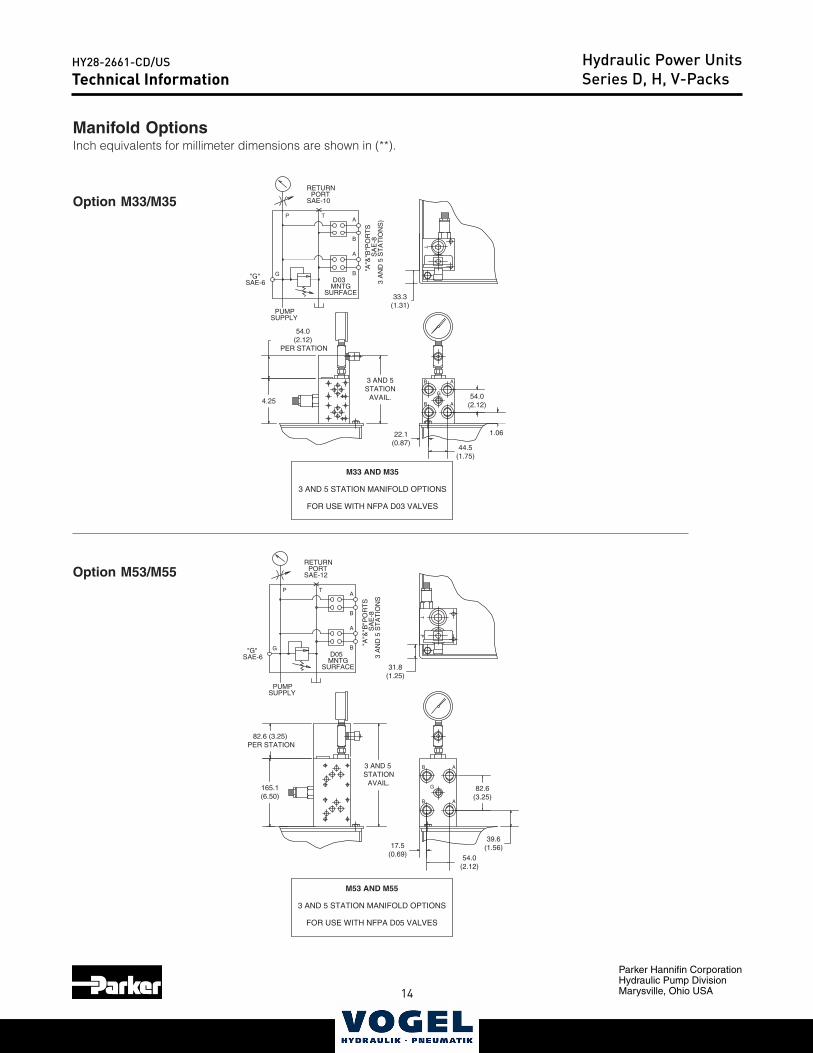
PUMPSUPPLY
A
B
RETURNPORT
SAE-12
D05MNTG
SURFACE
"A"&
"B"P
OR
TS
SA
E-8
3 A
ND
5 S
TA
TIO
NS
X
P T
A
AB
B
G
PT
A
BG"G"SAE-6
PUMPSUPPLY
A
B
RETURNPORT
SAE-10
D03MNTG
SURFACE
"A"&
"B"P
OR
TS
SA
E-8
3 A
ND
5 S
TA
TIO
NS
)
X
P T
AB
GT
A
BG"G"SAE-6
AB
33.3(1.31)
22.1(0.87)
44.5(1.75)
1.06
54.0(2.12)
31.8(1.25)
17.5(0.69) 54.0
(2.12)
39.6(1.56)
82.6(3.25)
165.1(6.50)
82.6 (3.25) PER STATION
3 AND 5 STATION
AVAIL.
54.0(2.12)
PER STATION
4.25
3 AND 5STATION
AVAIL.
M53 AND M55
3 AND 5 STATION MANIFOLD OPTIONS
FOR USE WITH NFPA D05 VALVES
M33 AND M35
3 AND 5 STATION MANIFOLD OPTIONS
FOR USE WITH NFPA D03 VALVES
Option M33/M35
Option M53/M55
Technical InformationHydraulic Power UnitsSeries D, H, V-Packs
14 15
Parker Hannifin CorporationHydraulic Pump DivisionMarysville, Ohio USA
HY28-2661-CD/USCatalog HY28-2661-CD/US
Volume ControlVertical Power Units
Parker Hannifin CorporationHydraulic Pump DivisionMaryville, Ohio USA
18
Technical Information Series D, H, V-Paks
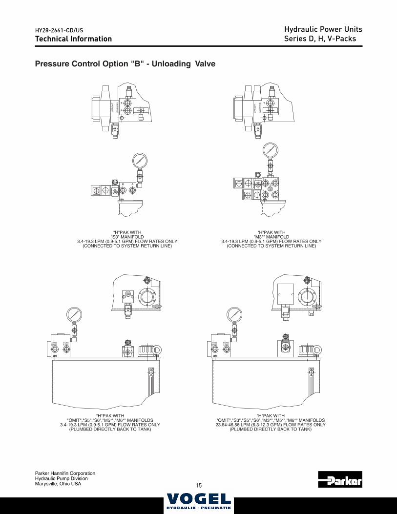
Pressure Control Option "B" - Unloading Valve
UP
RIG
HT
INV
ER
TE
D
A
T
B
B A
G
P
AB
T
INV
ER
TE
D
UP
RIG
HT
"H"PAK WITH"S3" MANIFOLD
3.4-19.3 LPM (0.9-5.1 GPM) FLOW RATES ONLY(CONNECTED TO SYSTEM RETURN LINE)
"H"PAK WITH"M3*" MANIFOLD
3.4-19.3 LPM (0.9-5.1 GPM) FLOW RATES ONLY(CONNECTED TO SYSTEM RETURN LINE)
"H"PAK WITH"OMIT","S5","S6","M5*","M6*" MANIFOLDS
3.4-19.3 LPM (0.9-5.1 GPM) FLOW RATES ONLY(PLUMBED DIRECTLY BACK TO TANK)
B-D03A-D05B-D05
A-D03
"H"PAK WITH"OMIT","S3","S5","S6","M3*","M5*","M6*" MANIFOLDS23.84-46.56 LPM (6.3-12.3 GPM) FLOW RATES ONLY
(PLUMBED DIRECTLY BACK TO TANK)
B-D05A-D03
A-D05B-D03
Technical InformationHydraulic Power UnitsSeries D, H, V-Packs
16
Parker Hannifin CorporationHydraulic Pump DivisionMarysville, Ohio USA
HY28-2661-CD/US
17
Catalog HY28-2661-CD/USVolume ControlVertical Power Units
Parker Hannifin CorporationHydraulic Pump DivisionMaryville, Ohio USA
19
Technical Information Series D, H, V-Paks
P
T
B A
T
B A
B A
G
INV
ER
TE
D
UP
RIG
HT
INV
ER
TE
D
UP
RIG
HT
P
T
B A
INV
ER
TE
D
UP
RIG
HT
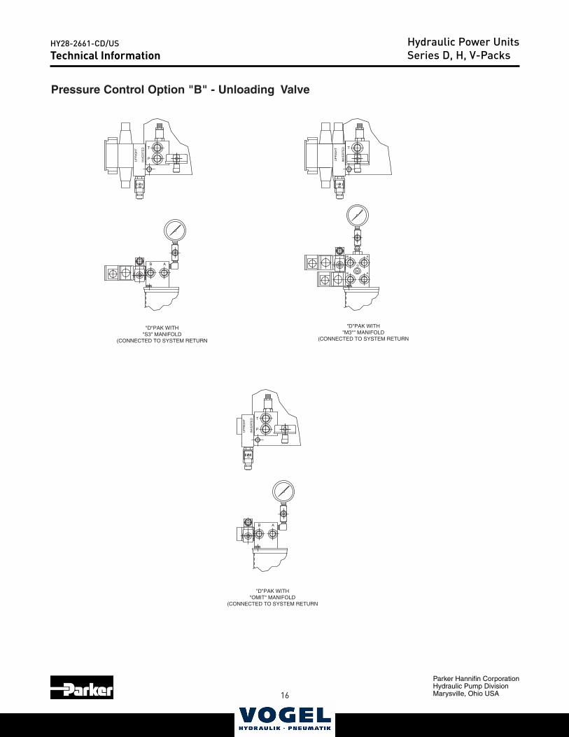
"D"PAK WITH"S3" MANIFOLD
(CONNECTED TO SYSTEM RETURN
"D"PAK WITH"M3*" MANIFOLD
(CONNECTED TO SYSTEM RETURN
"D"PAK WITH"OMIT" MANIFOLD
(CONNECTED TO SYSTEM RETURN
Pressure Control Option "B" - Unloading Valve
Technical InformationHydraulic Power UnitsSeries D, H, V-Packs
16 17
Parker Hannifin CorporationHydraulic Pump DivisionMarysville, Ohio USA
HY28-2661-CD/USCatalog HY28-2661-CD/US
Volume ControlVertical Power Units
Parker Hannifin CorporationHydraulic Pump DivisionMaryville, Ohio USA
20
Technical Information Series V-Paks
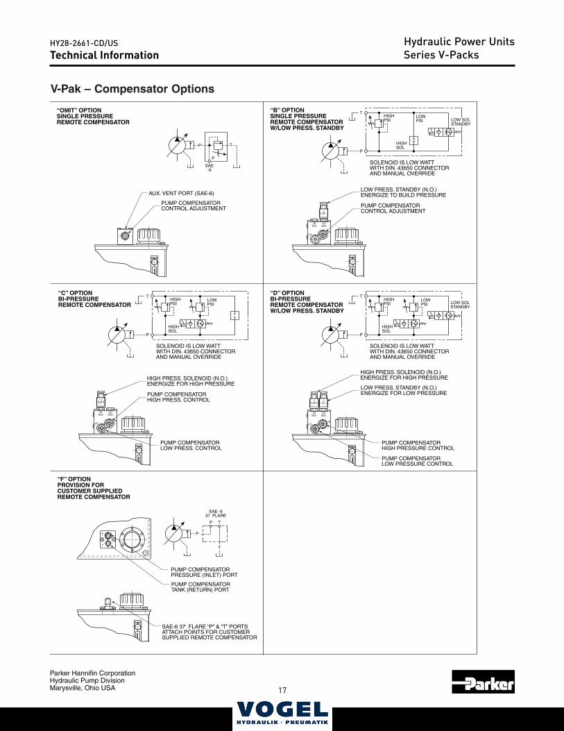
V-Pak – Compensator Options
HILO
HISOL
LOSOL
“OMIT” OPTIONSINGLE PRESSUREREMOTE COMPENSATOR
“B” OPTIONSINGLE PRESSUREREMOTE COMPENSATORW/LOW PRESS. STANDBY
“D” OPTIONBI-PRESSUREREMOTE COMPENSATORW/LOW PRESS. STANDBY
“C” OPTIONBI-PRESSUREREMOTE COMPENSATOR
PUMP COMPENSATORCONTROL ADJUSTMENT PUMP COMPENSATOR
CONTROL ADJUSTMENT
LOW PRESS. STANDBY (N.O.)ENERGIZE TO BUILD PRESSURE
LOWPSI
T
LOW SOLSTANDBY
HIGHPSI
HIGHSOLP
P
T
SOLENOID IS LOW WATTWITH DIN. 43650 CONNECTORAND MANUAL OVERRIDE
SAE-6
AUX. VENT PORT (SAE-6)
LOW PRESS. STANDBY (N.O.)ENERGIZE FOR LOW PRESSURE
HILO
HISOL
LOSOL
PUMP COMPENSATORHIGH PRESS. CONTROL
PUMP COMPENSATORLOW PRESS. CONTROL
HIGH PRESS. SOLENOID (N.O.)ENERGIZE FOR HIGH PRESSURE
HILO
HISOL
LOSOL
HIGH PRESS. SOLENOID (N.O.)ENERGIZE FOR HIGH PRESSURE
P
T
PUMP COMPENSATORPRESSURE (INLET) PORT
PUMP COMPENSATORTANK (RETURN) PORT
SAE-6 37 FLARE “P” & “T” PORTSATTACH POINTS FOR CUSTOMERSUPPLIED REMOTE COMPENSATOR
PUMP COMPENSATORHIGH PRESSURE CONTROL
PUMP COMPENSATORLOW PRESSURE CONTROL
P
LOWPSI
THIGHPSI
HIGHSOL
SOLENOID IS LOW WATTWITH DIN. 43650 CONNECTORAND MANUAL OVERRIDE
P
LOWPSI
THIGHPSI
HIGHSOL
LOW SOLSTANDBY
SOLENOID IS LOW WATTWITH DIN. 43650 CONNECTORAND MANUAL OVERRIDE
P
“F” OPTIONPROVISION FORCUSTOMER SUPPLIEDREMOTE COMPENSATOR
SAE -637 FLARE
P
P T
T
Technical InformationHydraulic Power UnitsSeries V-Packs
18
Parker Hannifin CorporationHydraulic Pump DivisionMarysville, Ohio USA
HY28-2661-CD/US
19
Catalog HY28-2661-CD/USVolume ControlVertical Power Units
Parker Hannifin CorporationHydraulic Pump DivisionMaryville, Ohio USA
21
A
N
M3/4"NPT
T
R
L
K
O
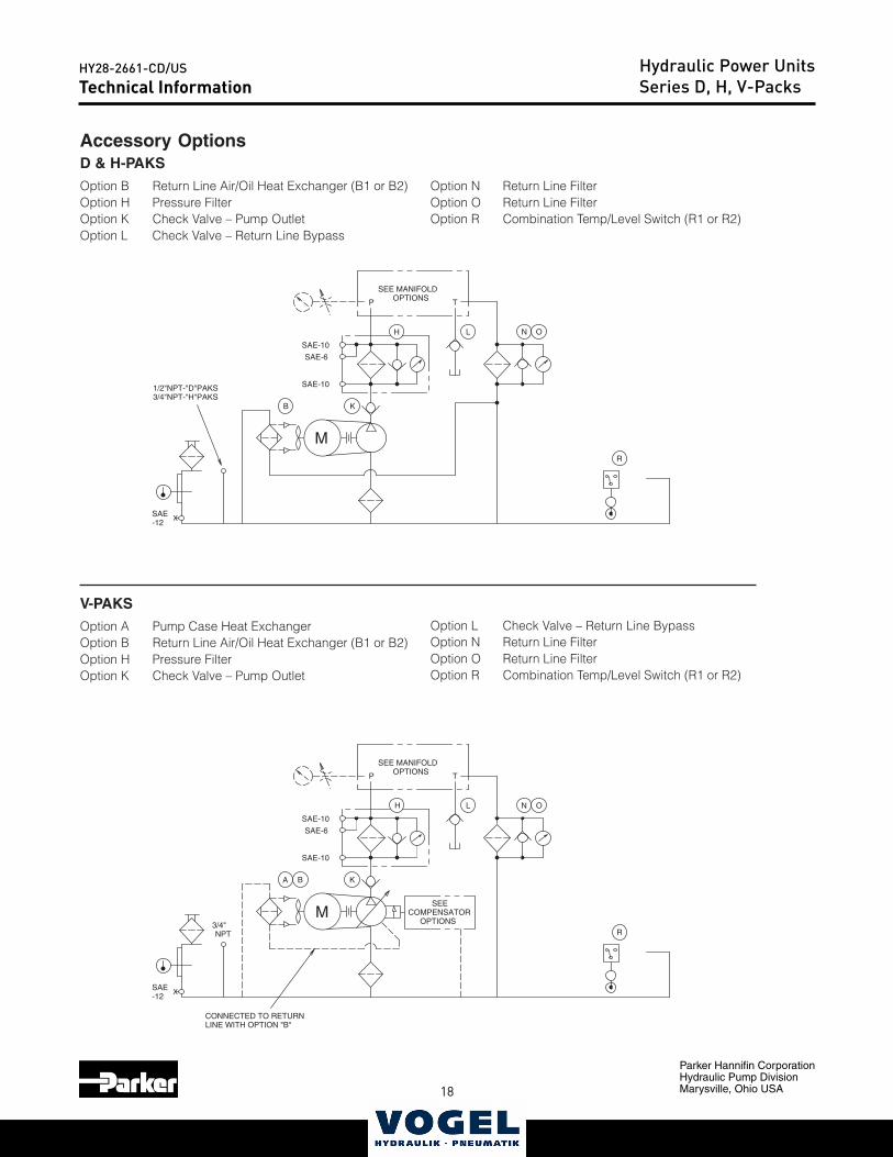
CONNECTED TO RETURNLINE WITH OPTION "B"
B
H
P
SEE MANIFOLDOPTIONS
SEECOMPENSATOR
OPTIONS
SAE-10
SAE-10
SAE-6
XSAE-12
B
N
M
1/2"NPT-"D"PAKS3/4"NPT-"H"PAKS
T
R
L
K
OH
P
SEE MANIFOLDOPTIONS
SAE-10
SAE-10
SAE-6
XSAE-12
Technical Information Series D, H, V-Paks
Accessory OptionsD & H-PAKS
Option B Return Line Air/Oil Heat Exchanger (B1 or B2)Option H Pressure FilterOption K Check Valve – Pump OutletOption L Check Valve – Return Line Bypass
V-PAKS
Option A Pump Case Heat ExchangerOption B Return Line Air/Oil Heat Exchanger (B1 or B2)Option H Pressure FilterOption K Check Valve – Pump Outlet
Option L Check Valve – Return Line BypassOption N Return Line FilterOption O Return Line FilterOption R Combination Temp/Level Switch (R1 or R2)
Option N Return Line FilterOption O Return Line FilterOption R Combination Temp/Level Switch (R1 or R2)
Technical InformationHydraulic Power UnitsSeries D, H, V-Packs
18 19
Parker Hannifin CorporationHydraulic Pump DivisionMarysville, Ohio USA
HY28-2661-CD/USCatalog HY28-2661-CD/US
Volume ControlVertical Power Units
Parker Hannifin CorporationHydraulic Pump DivisionMaryville, Ohio USA
22
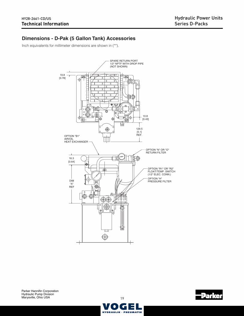
Technical Information Series D-Paks
Dimensions - D-Pak (5 Gallon Tank) AccessoriesInch equivalents for millimeter dimensions are shown in (**).
B A
P
T
OPTION "R1" OR "R2"FLOAT/TEMP. SWITCH(1/2" ELEC. CONN.)
OPTION "H"PRESSURE FILTER
SPARE RETURN PORT1/2" NPTF WITH DROP PIPE(NOT SHOWN)
OPTION "B1"AIR/OILHEAT EXCHANGER
OPTION "N" OR "O"RETURN FILTER
DIM"A"
REF
16.3[0.64]
19.8[0.78]
10.8 [0.43]
129.5[5.1]REF.
Technical InformationHydraulic Power UnitsSeries D-Packs
20
Parker Hannifin CorporationHydraulic Pump DivisionMarysville, Ohio USA
HY28-2661-CD/US
21
Catalog HY28-2661-CD/USVolume ControlVertical Power Units
Parker Hannifin CorporationHydraulic Pump DivisionMaryville, Ohio USA
23
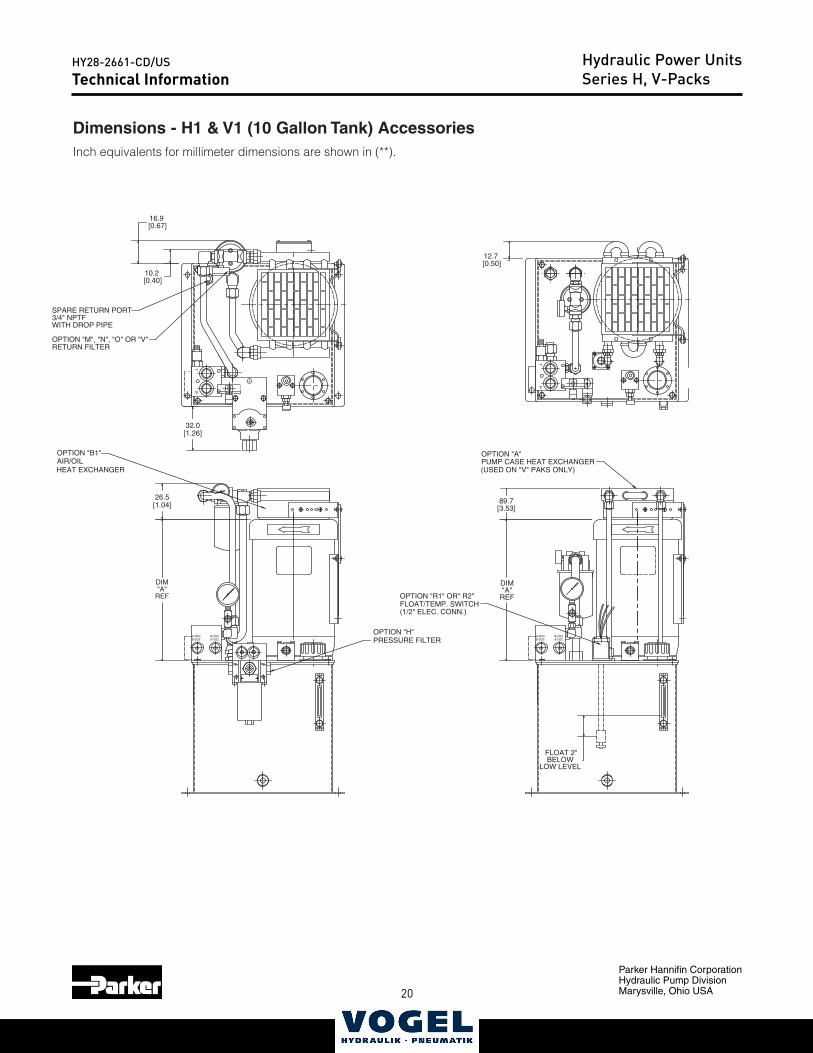
Technical Information Series H, V-Paks
Dimensions - H1 & V1 (10 Gallon Tank) AccessoriesInch equivalents for millimeter dimensions are shown in (**).
PT
PT
A-D03B-D05
B-D03A-D05
A-D03B-D05
B-D03A-D05
OPTION "A"PUMP CASE HEAT EXCHANGER(USED ON "V" PAKS ONLY)
OPTION "R1" OR" R2"FLOAT/TEMP. SWITCH(1/2" ELEC. CONN.)
OPTION "B1"AIR/OIL
OPTION "M", "N", "O" OR "V"RETURN FILTER
SPARE RETURN PORT3/4" NPTFWITH DROP PIPE
OPTION "H"PRESSURE FILTER
16.9 [0.67]
10.2 [0.40]
32.0[1.26]
26.5[1.04]
12.7 [0.50]
FLOAT 2"BELOW
LOW LEVEL
DIM"A"
REF
DIM"A"
REF
89.7[3.53]
HEAT EXCHANGER
Technical InformationHydraulic Power UnitsSeries H, V-Packs
20 21
Parker Hannifin CorporationHydraulic Pump DivisionMarysville, Ohio USA
HY28-2661-CD/USCatalog HY28-2661-CD/US
Volume ControlVertical Power Units
Parker Hannifin CorporationHydraulic Pump DivisionMaryville, Ohio USA
24
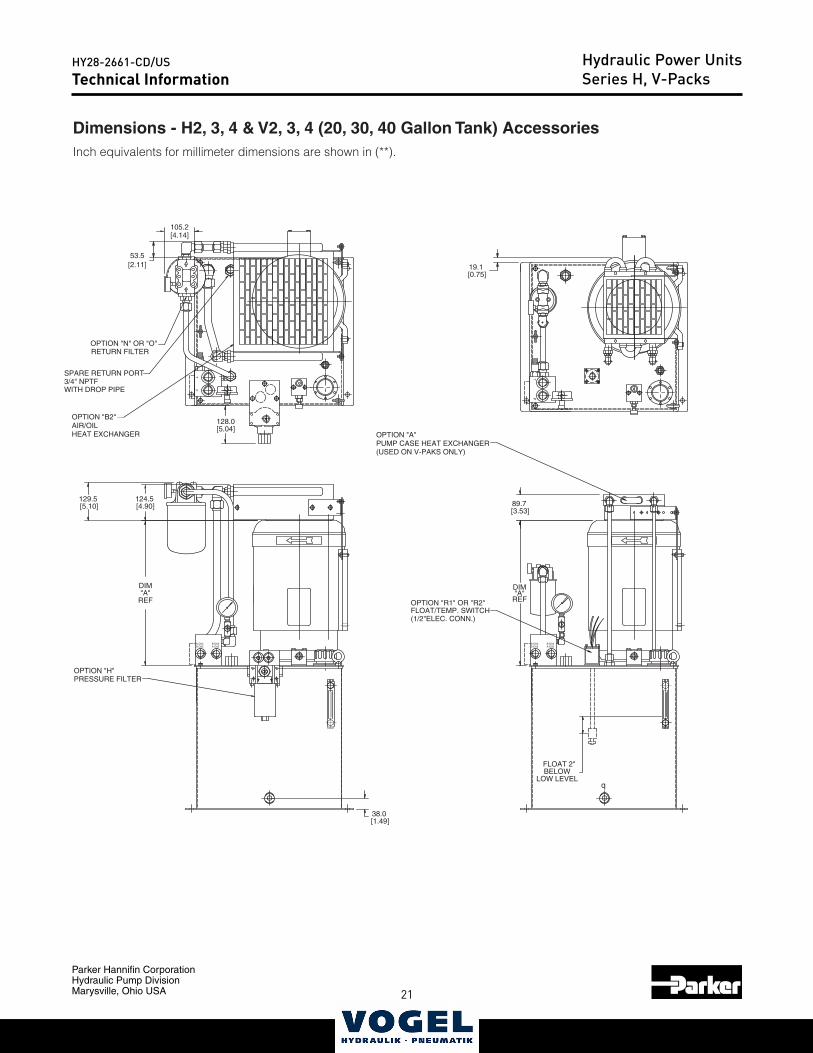
Technical Information Series H, V-Paks
Dimensions - H2, 3, 4 & V2, 3, 4 (20, 30, 40 Gallon Tank) AccessoriesInch equivalents for millimeter dimensions are shown in (**).
P
A-D03B-D05
B-D03A-D05
PT
A-D03B-D05
B-D03A-D05
q
T
OPTION "B2"AIR/OILHEAT EXCHANGER
OPTION "N" OR "O"RETURN FILTER
SPARE RETURN PORT3/4" NPTFWITH DROP PIPE
OPTION "R1" OR "R2"FLOAT/TEMP. SWITCH(1/2"ELEC. CONN.)
OPTION "H"PRESSURE FILTER
[4.14]
DIM"A"
REF
FLOAT 2"BELOW
LOW LEVEL
129.5 [5.10]
53.5[2.11]
(USED ON V-PAKS ONLY)PUMP CASE HEAT EXCHANGEROPTION "A"
DIM"A"
REF
105.2
124.5 [4.90]
38.0 [1.49]
128.0
19.1 [0.75]
[5.04]
89.7 [3.53]
Technical InformationHydraulic Power UnitsSeries H, V-Packs
22
Parker Hannifin CorporationHydraulic Pump DivisionMarysville, Ohio USA
HY28-2661-CD/US
23
Catalog HY28-2661-CD/USVolume ControlVertical Power Units
Parker Hannifin CorporationHydraulic Pump DivisionMaryville, Ohio USA
25
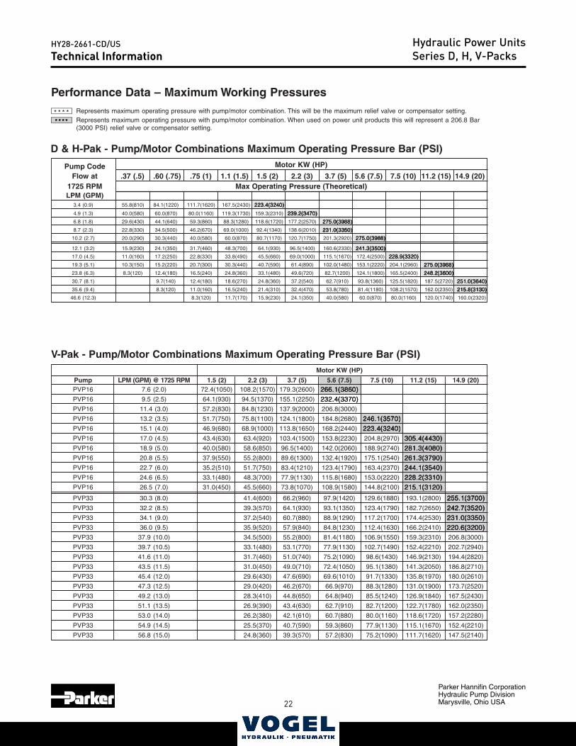
Pump Code Motor KW (HP)
Flow at .37 (.5) .60 (.75) .75 (1) 1.1 (1.5) 1.5 (2) 2.2 (3) 3.7 (5) 5.6 (7.5) 7.5 (10) 11.2 (15) 14.9 (20)1725 RPM Max Operating Pressure (Theoretical)LPM (GPM)
3.4 (0.9) 55.8(810) 84.1(1220) 111.7(1620) 167.5(2430) 223.4(3240)223.4(3240)223.4(3240)223.4(3240)223.4(3240)
4.9 (1.3) 40.0(580) 60.0(870) 80.0(1160) 119.3(1730) 159.3(2310) 239.2(3470)239.2(3470)239.2(3470)239.2(3470)239.2(3470)
6.8 (1.8) 29.6(430) 44.1(640) 59.3(860) 88.3(1280) 118.6(1720) 177.2(2570) 275.0(3988)275.0(3988)275.0(3988)275.0(3988)275.0(3988)
8.7 (2.3) 22.8(330) 34.5(500) 46.2(670) 69.0(1000) 92.4(1340) 138.6(2010) 231.0(3350)231.0(3350)231.0(3350)231.0(3350)231.0(3350)
10.2 (2.7) 20.0(290) 30.3(440) 40.0(580) 60.0(870) 80.7(1170) 120.7(1750) 201.3(2920) 275.0(3988)275.0(3988)275.0(3988)275.0(3988)275.0(3988)
12.1 (3.2) 15.9(230) 24.1(350) 31.7(460) 48.3(700) 64.1(930) 96.5(1400) 160.6(2330) 241.3(3500)241.3(3500)241.3(3500)241.3(3500)241.3(3500)
17.0 (4.5) 11.0(160) 17.2(250) 22.8(330) 33.8(490) 45.5(660) 69.0(1000) 115.1(1670) 172.4(2500) 228.9(3320)228.9(3320)228.9(3320)228.9(3320)228.9(3320)
19.3 (5.1) 10.3(150) 15.2(220) 20.7(300) 30.3(440) 40.7(590) 61.4(890) 102.0(1480) 153.1(2220) 204.1(2960) 275.0(3988)275.0(3988)275.0(3988)275.0(3988)275.0(3988)
23.8 (6.3) 8.3(120) 12.4(180) 16.5(240) 24.8(360) 33.1(480) 49.6(720) 82.7(1200) 124.1(1800) 165.5(2400) 248.2(3600)248.2(3600)248.2(3600)248.2(3600)248.2(3600)
30.7 (8.1) 9.7(140) 12.4(180) 18.6(270) 24.8(360) 37.2(540) 62.7(910) 93.8(1360) 125.5(1820) 187.5(2720) 251.0(3640)251.0(3640)251.0(3640)251.0(3640)251.0(3640)
35.6 (9.4) 8.3(120) 11.0(160) 16.5(240) 21.4(310) 32.4(470) 53.8(780) 81.4(1180) 108.2(1570) 162.0(2350) 215.8(3130)215.8(3130)215.8(3130)215.8(3130)215.8(3130)
46.6 (12.3) 8.3(120) 11.7(170) 15.9(230) 24.1(350) 40.0(580) 60.0(870) 80.0(1160) 120.0(1740) 160.0(2320)
Technical Information Series D, H, V-Paks
Performance Data – Maximum Working Pressures
D & H-Pak - Pump/Motor Combinations Maximum Operating Pressure Bar (PSI)
* * * * Represents maximum operating pressure with pump/motor combination. This will be the maximum relief valve or compensator setting.
* * ** * ** * ** * ** * * ***** Represents maximum operating pressure with pump/motor combination. When used on power unit products this will represent a 206.8 Bar(3000 PSI) relief valve or compensator setting.
V-Pak - Pump/Motor Combinations Maximum Operating Pressure Bar (PSI)Motor KW (HP)
Pump LPM (GPM) @ 1725 RPM 1.5 (2) 2.2 (3) 3.7 (5) 5.6 (7.5) 7.5 (10) 11.2 (15) 14.9 (20)PVP16 7.6 (2.0) 72.4(1050) 108.2(1570) 179.3(2600) 266.1(3860)266.1(3860)266.1(3860)266.1(3860)266.1(3860)
PVP16 9.5 (2.5) 64.1(930) 94.5(1370) 155.1(2250) 232.4(3370)232.4(3370)232.4(3370)232.4(3370)232.4(3370)
PVP16 11.4 (3.0) 57.2(830) 84.8(1230) 137.9(2000) 206.8(3000)
PVP16 13.2 (3.5) 51.7(750) 75.8(1100) 124.1(1800) 184.8(2680) 246.1(3570)246.1(3570)246.1(3570)246.1(3570)246.1(3570)
PVP16 15.1 (4.0) 46.9(680) 68.9(1000) 113.8(1650) 168.2(2440) 223.4(3240)223.4(3240)223.4(3240)223.4(3240)223.4(3240)
PVP16 17.0 (4.5) 43.4(630) 63.4(920) 103.4(1500) 153.8(2230) 204.8(2970) 305.4(4430)305.4(4430)305.4(4430)305.4(4430)305.4(4430)
PVP16 18.9 (5.0) 40.0(580) 58.6(850) 96.5(1400) 142.0(2060) 188.9(2740) 281.3(4080)281.3(4080)281.3(4080)281.3(4080)281.3(4080)
PVP16 20.8 (5.5) 37.9(550) 55.2(800) 89.6(1300) 132.4(1920) 175.1(2540) 261.3(3790)261.3(3790)261.3(3790)261.3(3790)261.3(3790)
PVP16 22.7 (6.0) 35.2(510) 51.7(750) 83.4(1210) 123.4(1790) 163.4(2370) 244.1(3540)244.1(3540)244.1(3540)244.1(3540)244.1(3540)
PVP16 24.6 (6.5) 33.1(480) 48.3(700) 77.9(1130) 115.8(1680) 153.0(2220) 228.2(3310)228.2(3310)228.2(3310)228.2(3310)228.2(3310)
PVP16 26.5 (7.0) 31.0(450) 45.5(660) 73.8(1070) 108.9(1580) 144.8(2100) 215.1(3120)215.1(3120)215.1(3120)215.1(3120)215.1(3120)
PVP33 30.3 (8.0) 41.4(600) 66.2(960) 97.9(1420) 129.6(1880) 193.1(2800) 255.1(3700)255.1(3700)255.1(3700)255.1(3700)255.1(3700)
PVP33 32.2 (8.5) 39.3(570) 64.1(930) 93.1(1350) 123.4(1790) 182.7(2650) 242.7(3520)242.7(3520)242.7(3520)242.7(3520)242.7(3520)
PVP33 34.1 (9.0) 37.2(540) 60.7(880) 88.9(1290) 117.2(1700) 174.4(2530) 231.0(3350)231.0(3350)231.0(3350)231.0(3350)231.0(3350)
PVP33 36.0 (9.5) 35.9(520) 57.9(840) 84.8(1230) 112.4(1630) 166.2(2410) 220.6(3200)220.6(3200)220.6(3200)220.6(3200)220.6(3200)
PVP33 37.9 (10.0) 34.5(500) 55.2(800) 81.4(1180) 106.9(1550) 159.3(2310) 206.8(3000)
PVP33 39.7 (10.5) 33.1(480) 53.1(770) 77.9(1130) 102.7(1490) 152.4(2210) 202.7(2940)
PVP33 41.6 (11.0) 31.7(460) 51.0(740) 75.2(1090) 98.6(1430) 146.9(2130) 194.4(2820)
PVP33 43.5 (11.5) 31.0(450) 49.0(710) 72.4(1050) 95.1(1380) 141.3(2050) 186.8(2710)
PVP33 45.4 (12.0) 29.6(430) 47.6(690) 69.6(1010) 91.7(1330) 135.8(1970) 180.0(2610)
PVP33 47.3 (12.5) 29.0(420) 46.2(670) 66.9(970) 88.3(1280) 131.0(1900) 173.7(2520)
PVP33 49.2 (13.0) 28.3(410) 44.8(650) 64.8(940) 85.5(1240) 126.9(1840) 167.5(2430)
PVP33 51.1 (13.5) 26.9(390) 43.4(630) 62.7(910) 82.7(1200) 122.7(1780) 162.0(2350)
PVP33 53.0 (14.0) 26.2(380) 42.1(610) 60.7(880) 80.0(1160) 118.6(1720) 157.2(2280)
PVP33 54.9 (14.5) 25.5(370) 40.7(590) 59.3(860) 77.9(1130) 115.1(1670) 152.4(2210)
PVP33 56.8 (15.0) 24.8(360) 39.3(570) 57.2(830) 75.2(1090) 111.7(1620) 147.5(2140)
Technical InformationHydraulic Power UnitsSeries D, H, V-Packs
22 23
Parker Hannifin CorporationHydraulic Pump DivisionMarysville, Ohio USA
HY28-2661-CD/USCatalog HY28-2661-CD/US
Volume ControlVertical Power Units
Parker Hannifin CorporationHydraulic Pump DivisionMaryville, Ohio USA
26
8
10
12
14
16
18
20100
90
80
70
60
50
Flo
w
Eff
icie
ncy
- %
Po
wer
PVP33 @ 1800 RPM
0
4
2
6
30.3
37.9
45.4
53.0
60.6
68.2
75.7
0
15.1
7.6
22.7
0
0
Bar
PSI69
1000
138
2000
207
3000
275
4000
Pressure
GPMLPM
0
6.0
11.9
17.9
23.9
29.8
0
8.0
16.0
24.0
32.0
40.0HPKW
Volumetric Efficiency
Overall Efficiency
Flow
Input Power a
t Full F
low
Compensated Power
4
5
6
7
8
9
10100
90
80
70
60
Flo
w
Eff
icie
ncy
- %
Po
wer
PVP16 @ 1800 RPM
0
2
1
3
15.1
18.9
22.7
26.5
30.3
34.1
37.9
0
7.6
3.8
11.4
0
0
Bar
PSI69
1000
138
2000
207
3000
275
4000
Pressure
GPMLPM
0
3.0
6.0
8.9
11.9
14.9
0
4.0
8.0
12.0
16.0
20.0HPKW
Volumetric Efficiency
Overall Efficiency
Flow
Input Power a
t Full F
low
Compensated Power
Technical Information Series D, H, V-Paks
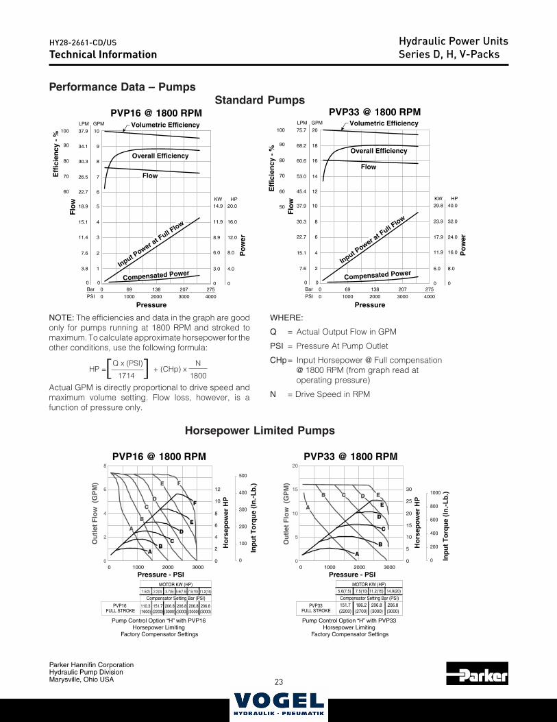
Performance Data – Pumps
[ ]HP = Q x (PSI) + (CHp) xN
1714 1800
NOTE: The efficiencies and data in the graph are goodonly for pumps running at 1800 RPM and stroked tomaximum. To calculate approximate horsepower for theother conditions, use the following formula:
Actual GPM is directly proportional to drive speed andmaximum volume setting. Flow loss, however, is afunction of pressure only.
WHERE:
Q = Actual Output Flow in GPM
PSI = Pressure At Pump Outlet
CHp= Input Horsepower @ Full compensation@ 1800 RPM (from graph read atoperating pressure)
N = Drive Speed in RPM
Horsepower Limited Pumps
Standard Pumps
A
B
C
A
B C D E
D
E
0
200
400
600
800
1000
AB
C
D
E
F
A
B
CD
E F
0
100
200
300
400
500
PVP16FULL STROKE
1.5(2) 2.2(3) 3.7(5) 5.6(7.5) 7.5(10)
110.3(1600)
151.7(2200)
206.8(3000)
206.8(3000)
MOTOR KW (HP)
Compensator Setting Bar (PSI)
206.8(3000)
206.8(3000)
Pump Control Option “H” with PVP16Horsepower Limiting
Factory Compensator Settings
Pump Control Option “H” with PVP33Horsepower Limiting
Factory Compensator Settings
PVP33FULL STROKE
5.6(7.5) 7.5(10) 11.2(15) 14.9(20)
151.7(2200)
186.2(2700)
206.8(3000)
MOTOR KW (HP)
Compensator Setting Bar (PSI)206.8(3000)
11.2(15)
30
0
10
20
0
Ou
tlet
Flo
w (
GP
M)
Ho
rsep
ow
er H
P
Inp
ut
To
rqu
e (I
n.-
Lb
.)
0 20001000 3000
Pressure - PSI
20
15
10
5
PVP33 @ 1800 RPM
12
0
4
8
0
Ou
tlet
Flo
w (
GP
M)
Ho
rsep
ow
er H
P
Inp
ut
To
rqu
e (I
n.-
Lb
.)
0 20001000 3000
Pressure - PSI
8
6
4
2
25
5
15
10
2
6
PVP16 @ 1800 RPM
Technical InformationHydraulic Power UnitsSeries D, H, V-Packs
24
Parker Hannifin CorporationHydraulic Pump DivisionMarysville, Ohio USA
HY28-2661-CD/US
25
Catalog HY28-2661-CD/USVolume ControlVertical Power Units
Parker Hannifin CorporationHydraulic Pump DivisionMaryville, Ohio USA
27
Technical Information Series D, H, V-Paks
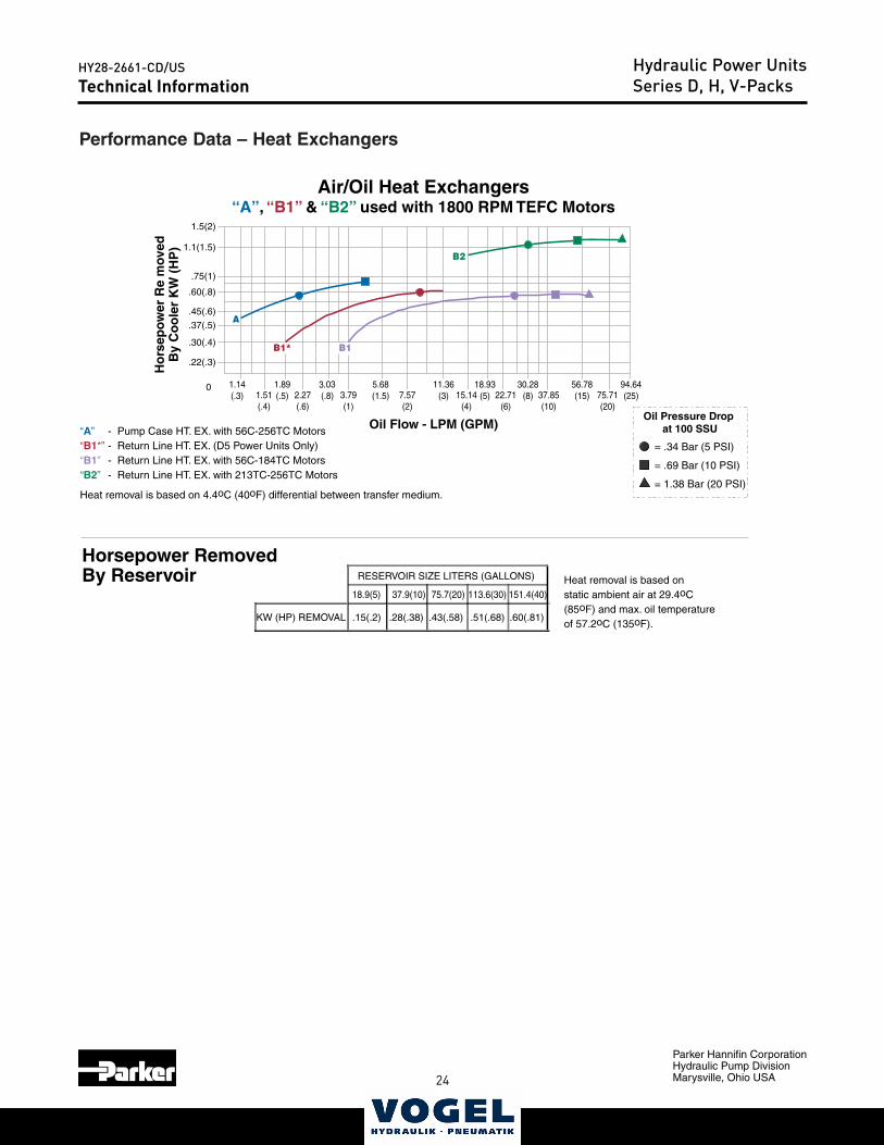
Performance Data – Heat Exchangers
1.14(.3)
Ho
rsep
ow
er R
e m
oved
By
Co
ole
r K
W (
HP
)
KW (HP) REMOVAL
18.9(5) 37.9(10) 75.7(20) 113.6(30) 151.4(40)
.15(.2) .28(.38) .43(.58) .51(.68)
RESERVOIR SIZE LITERS (GALLONS)
.60(.81)
1.51(.4)
1.89(.5) 2.27
(.6)
3.03(.8) 3.79
(1)
5.68(1.5) 7.57
(2)
11.36(3) 15.14
(4)
18.93(5) 22.71
(6)
30.28(8) 37.85
(10)
56.78(15) 75.71
(20)
94.64(25)
.22(.3)
.30(.4)
.37(.5)
.45(.6)
.60(.8)
.75(1)
1.1(1.5)
1.5(2)
A
B1
B2
Oil Flow - LPM (GPM)
Air/Oil Heat Exchangers“A”, “B1” & “B2” used with 1800 RPM TEFC Motors
= .34 Bar (5 PSI)
= .69 Bar (10 PSI)
= 1.38 Bar (20 PSI)
Oil Pressure Drop at 100 SSU“A” - Pump Case HT. EX. with 56C-256TC Motors
“B1*” - Return Line HT. EX. (D5 Power Units Only)“B1” - Return Line HT. EX. with 56C-184TC Motors“B2” - Return Line HT. EX. with 213TC-256TC Motors Heat removal is based on 4.4oC (40oF) differential between transfer medium.
0
Horsepower RemovedBy Reservoir Heat removal is based on
static ambient air at 29.4oC(85oF) and max. oil temperatureof 57.2oC (135oF).
B1*
Technical InformationHydraulic Power UnitsSeries D, H, V-Packs
24 25
Parker Hannifin CorporationHydraulic Pump DivisionMarysville, Ohio USA
HY28-2661-CD/US
NotesHydraulic Power Units
26
Parker Hannifin CorporationHydraulic Pump DivisionMarysville, Ohio USA
HY28-2661-CD/US
27
IntroductionHydraulic Power UnitsV-Pak Low Profile SeriesCatalog HY13-1552-002/US,EU
Volume ControlLow Profile Power UnitsSeries V-Paks
Parker Hannifin CorporationHydraulic Pump DivisionMarysville, Ohio USA
2
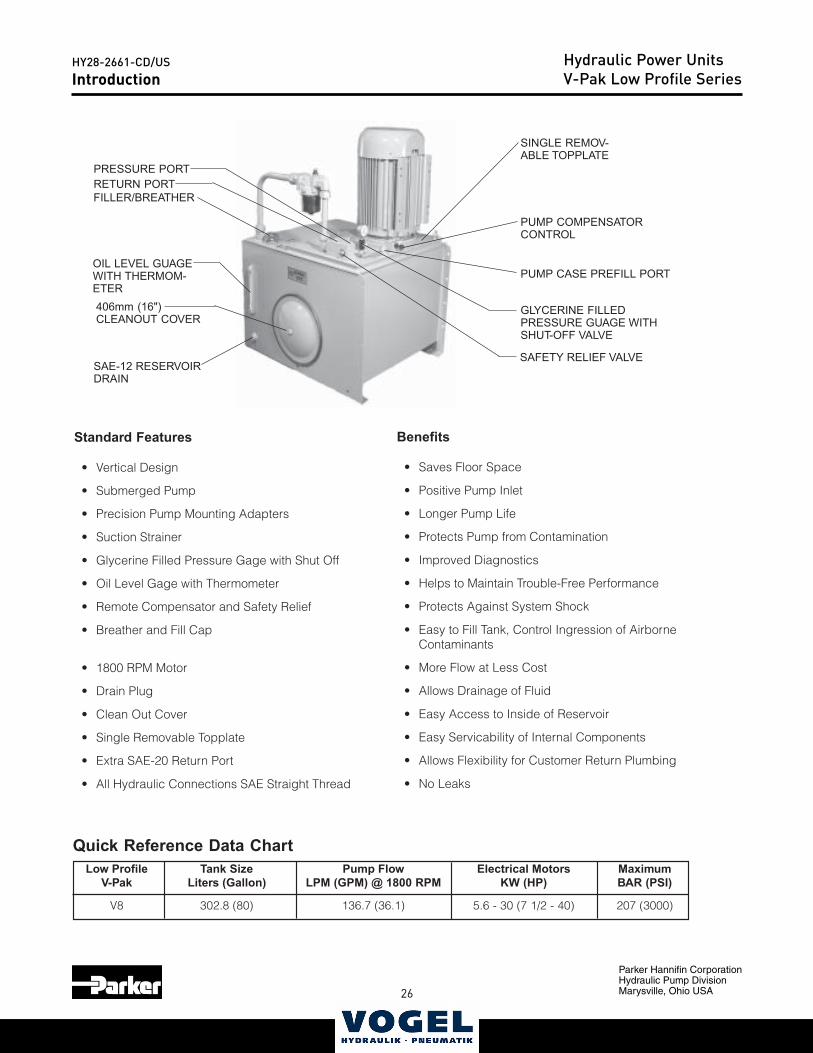
Introduction
Low Profile Tank Size Pump Flow Electrical Motors MaximumV-Pak Liters (Gallon) LPM (GPM) @ 1800 RPM KW (HP) BAR (PSI)
V8 302.8 (80) 136.7 (36.1) 5.6 - 30 (7 1/2 - 40) 207 (3000)
Quick Reference Data Chart
PUMP COMPENSATORCONTROL
SINGLE REMOV-ABLE TOPPLATE
GLYCERINE FILLEDPRESSURE GUAGE WITHSHUT-OFF VALVE
PUMP CASE PREFILL PORT
PRESSURE PORTRETURN PORT
SAE-12 RESERVOIRDRAIN
SAFETY RELIEF VALVE
Standard Features
• Vertical Design
• Submerged Pump
• Precision Pump Mounting Adapters
• Suction Strainer
• Glycerine Filled Pressure Gage with Shut Off
• Oil Level Gage with Thermometer
• Remote Compensator and Safety Relief
• Breather and Fill Cap
• 1800 RPM Motor
• Drain Plug
• Clean Out Cover
• Single Removable Topplate
• Extra SAE-20 Return Port
• All Hydraulic Connections SAE Straight Thread
Benefits
• Saves Floor Space
• Positive Pump Inlet
• Longer Pump Life
• Protects Pump from Contamination
• Improved Diagnostics
• Helps to Maintain Trouble-Free Performance
• Protects Against System Shock
• Easy to Fill Tank, Control Ingression of AirborneContaminants
• More Flow at Less Cost
• Allows Drainage of Fluid
• Easy Access to Inside of Reservoir
• Easy Servicability of Internal Components
• Allows Flexibility for Customer Return Plumbing
• No Leaks
FILLER/BREATHER
OIL LEVEL GUAGEWITH THERMOM-ETER406mm (16")CLEANOUT COVER
26 27
Parker Hannifin CorporationHydraulic Pump DivisionMarysville, Ohio USA
HY28-2661-CD/US Hydraulic Power UnitsV-Pak Low Profile SeriesIntroductionCatalog HY13-1552-002/US,EU
Volume ControlLow Profile Power UnitsSeries V-Paks
Parker Hannifin CorporationHydraulic Pump DivisionMarysville, Ohio USA
3
SAE-20SPARE
RETURN
SAE-12
M
X
“O”OPTION
MANIFOLD
“OMIT”OPTIONCOMP
CONTROL
V-PAK BASIC UNIT—————————NO OPTIONS OR ACCESSORIES
“OMIT” OPTION PUMP COMPENSATOR“O” OPTION MANIFOLD
P T
SUPPLY PORT SAE-16
RETURN PORT SAE-20
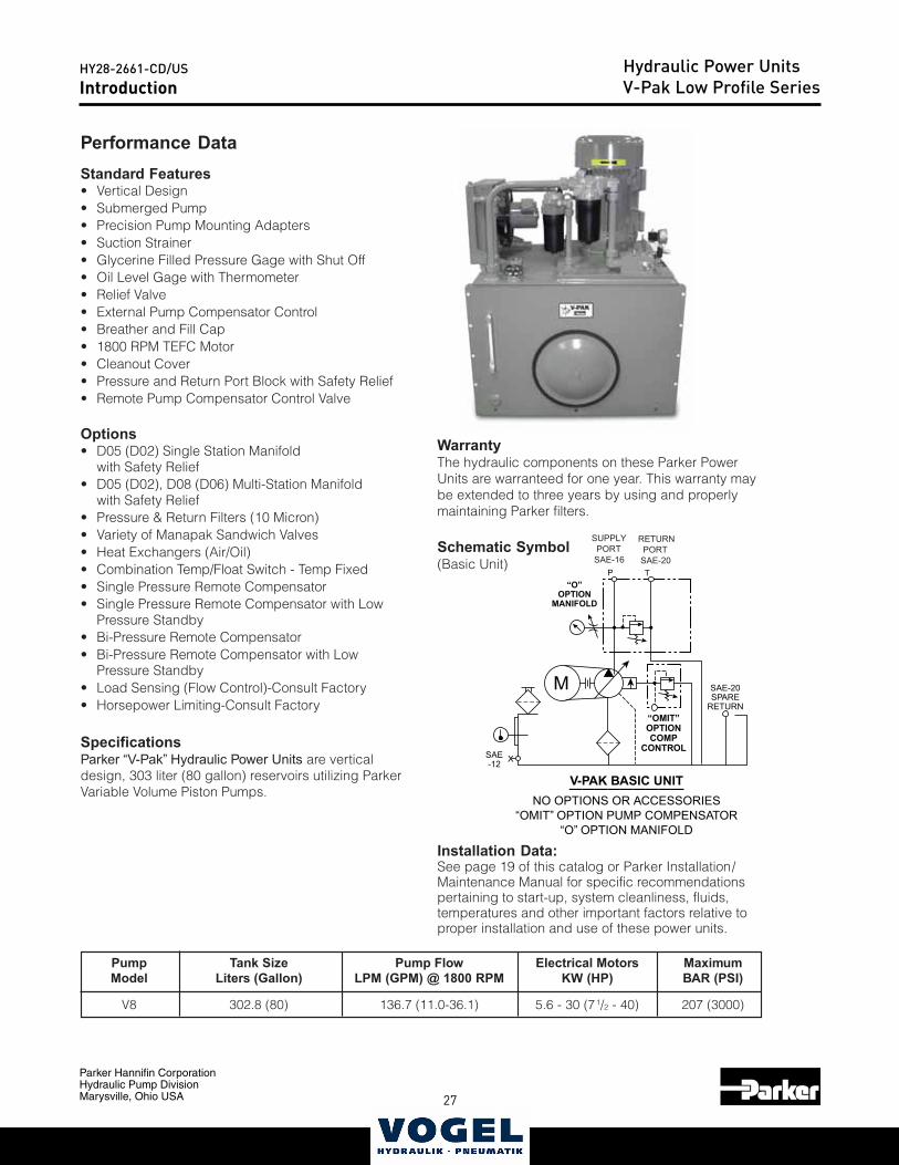
WarrantyThe hydraulic components on these Parker PowerUnits are warranteed for one year. This warranty maybe extended to three years by using and properlymaintaining Parker filters.
Schematic Symbol(Basic Unit)
Installation Data:See page 19 of this catalog or Parker Installation/Maintenance Manual for specific recommendationspertaining to start-up, system cleanliness, fluids,temperatures and other important factors relative toproper installation and use of these power units.
Performance DataStandard Features• Vertical Design• Submerged Pump• Precision Pump Mounting Adapters• Suction Strainer• Glycerine Filled Pressure Gage with Shut Off• Oil Level Gage with Thermometer• Relief Valve• External Pump Compensator Control• Breather and Fill Cap• 1800 RPM TEFC Motor• Cleanout Cover• Pressure and Return Port Block with Safety Relief• Remote Pump Compensator Control Valve
Options• D05 (D02) Single Station Manifold
with Safety Relief• D05 (D02), D08 (D06) Multi-Station Manifold
with Safety Relief• Pressure & Return Filters (10 Micron)• Variety of Manapak Sandwich Valves• Heat Exchangers (Air/Oil)• Combination Temp/Float Switch - Temp Fixed• Single Pressure Remote Compensator• Single Pressure Remote Compensator with Low
Pressure Standby• Bi-Pressure Remote Compensator• Bi-Pressure Remote Compensator with Low
Pressure Standby• Load Sensing (Flow Control)-Consult Factory• Horsepower Limiting-Consult Factory
SpecificationsParker “V-Pak” Hydraulic Power Units are verticaldesign, 303 liter (80 gallon) reservoirs utilizing ParkerVariable Volume Piston Pumps.
Introduction
Pump Tank Size Pump Flow Electrical Motors MaximumModel Liters (Gallon) LPM (GPM) @ 1800 RPM KW (HP) BAR (PSI)
V8 302.8 (80) 136.7 (11.0-36.1) 5.6 - 30 (71/2 - 40) 207 (3000)
28
Parker Hannifin CorporationHydraulic Pump DivisionMarysville, Ohio USA
HY28-2661-CD/US
29
V-Pak Low Profile Ordering InformationHydraulic Power UnitsV-Pak Low Profile Series
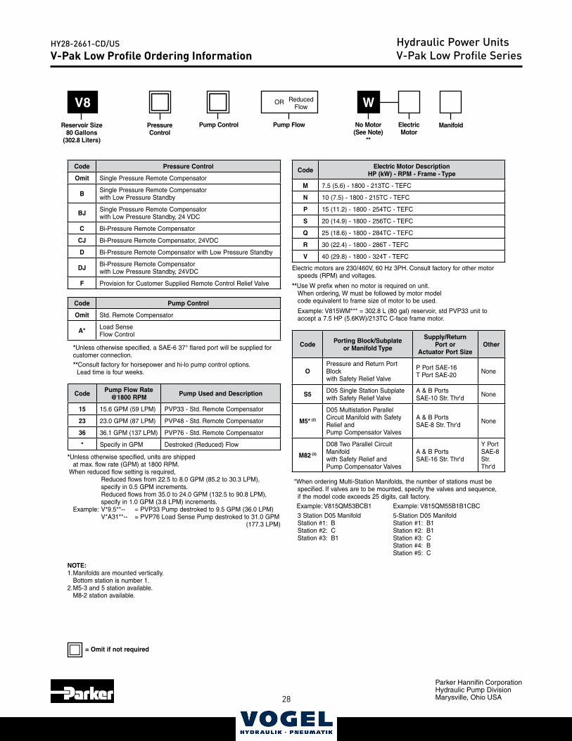
Code Electric Motor DescriptionHP (kW) - RPM - Frame - Type
M 7.5 (5.6) - 1800 - 213TC - TEFC
N 10 (7.5) - 1800 - 215TC - TEFC
P 15 (11.2) - 1800 - 254TC - TEFC
S 20 (14.9) - 1800 - 256TC - TEFC
Q 25 (18.6) - 1800 - 284TC - TEFC
R 30 (22.4) - 1800 - 286T - TEFC
V 40 (29.8) - 1800 - 324T - TEFC
Electric motors are 230/460V, 60 Hz 3PH. Consult factory for other motor speeds (RPM) and voltages.
**Use W prefix when no motor is required on unit. When ordering, W must be followed by motor model code equivalent to frame size of motor to be used.
Example: V815WM*** = 302.8 L (80 gal) reservoir, std PVP33 unit to accept a 7.5 HP (5.6KW)/213TC C-face frame motor.
WV8
Reservoir Size 80 Gallons
(302.8 Liters)
No Motor (See Note)
**
Code Pressure Control
Omit Single Pressure Remote Compensator
B Single Pressure Remote Compensator with Low Pressure Standby
BJ Single Pressure Remote Compensator with Low Pressure Standby, 24 VDC
C Bi-Pressure Remote Compensator
CJ Bi-Pressure Remote Compensator, 24VDC
D Bi-Pressure Remote Compensator with Low Pressure Standby
DJ Bi-Pressure Remote Compensator with Low Pressure Standby, 24VDC
F Provision for Customer Supplied Remote Control Relief Valve
Code Porting Block/Subplate or Manifold Type
Supply/Return Port or
Actuator Port SizeOther
OPressure and Return Port Block with Safety Relief Valve
P Port SAE-16T Port SAE-20 None
S5 D05 Single Station Subplate with Safety Relief Valve
A & B PortsSAE-10 Str. Thr'd None
M5* (2)
D05 Multistation Parallel Circuit Manifold with Safety Relief and Pump Compensator Valves
A & B PortsSAE-8 Str. Thr'd None
M82 (3)
D08 Two Parallel Circuit Manifold with Safety Relief and Pump Compensator Valves
A & B PortsSAE-16 Str. Thr'd
Y PortSAE-8 Str. Thr'd
*When ordering Multi-Station Manifolds, the number of stations must be specified. If valves are to be mounted, specify the valves and sequence, if the model code exceeds 25 digits, call factory.
Example: V815QM53BCB1 Example: V815QM55B1B1CBC
3 Station D05 Manifold 5-Station D05 Manifold Station #1: B Station #1: B1 Station #2: C Station #2: B1 Station #3: B1 Station #3: C Station #4: B Station #5: C
NOTE: 1. Manifolds are mounted vertically.
Bottom station is number 1.2. M5-3 and 5 station available.
M8-2 station available.
Pressure Control
Pump Control ElectricMotor
Manifold
Code Pump Control
Omit Std. Remote Compensator
A* Load Sense Flow Control
*Unless otherwise specified, a SAE-6 37° flared port will be supplied for customer connection.
**Consult factory for horsepower and hi-lo pump control options. Lead time is four weeks.
Pump Flow
Code Pump Flow Rate @1800 RPM Pump Used and Description
15 15.6 GPM (59 LPM) PVP33 - Std. Remote Compensator
23 23.0 GPM (87 LPM) PVP48 - Std. Remote Compensator
36 36.1 GPM (137 LPM) PVP76 - Std. Remote Compensator
* Specify in GPM Destroked (Reduced) Flow
*Unless otherwise specified, units are shipped at max. flow rate (GPM) at 1800 RPM.
When reduced flow setting is required, Reduced flows from 22.5 to 8.0 GPM (85.2 to 30.3 LPM),
specify in 0.5 GPM increments. Reduced flows from 35.0 to 24.0 GPM (132.5 to 90.8 LPM),
specify in 1.0 GPM (3.8 LPM) increments. Example: V*9.5**-- = PVP33 Pump destroked to 9.5 GPM (36.0 LPM)
V*A31**-- = PVP76 Load Sense Pump destroked to 31.0 GPM (177.3 LPM)
= Omit if not required
Reduced Flow
OR
28 29
Parker Hannifin CorporationHydraulic Pump DivisionMarysville, Ohio USA
HY28-2661-CD/US Hydraulic Power UnitsV-Pak Low Profile SeriesV-Pak Low Profile Ordering Information
P
Code
ManapakControlValves
Function
Valve Model Number
NFPA Mounting
Pad
Nominal Flow GPM (LPM) Circuit Symbol
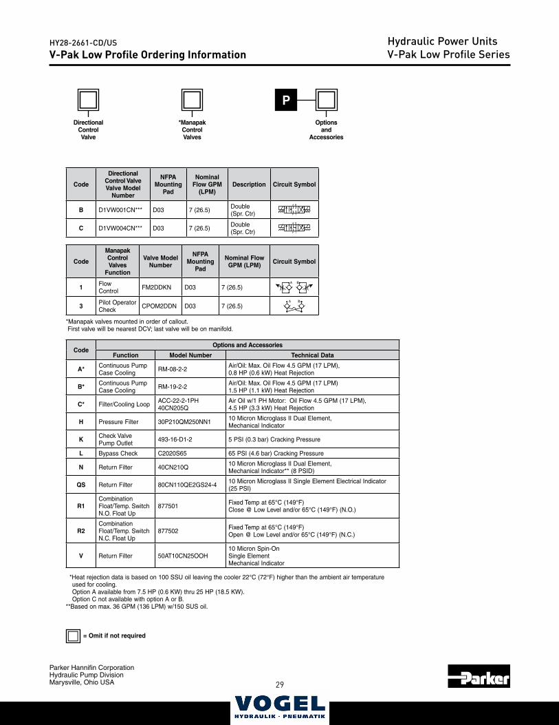
1 Flow Control FM2DDKN D03 7 (26.5)
A B
3 Pilot Operator Check CPOM2DDN D03 7 (26.5)
A B
*Manapak valves mounted in order of callout. First valve will be nearest DCV; last valve will be on manifold.
CodeOptions and Accessories
Function Model Number Technical Data
A* Continuous Pump Case Cooling RM-08-2-2 Air/Oil: Max. Oil Flow 4.5 GPM (17 LPM),
0.8 HP (0.6 kW) Heat Rejection
B* Continuous Pump Case Cooling RM-19-2-2 Air/Oil: Max. Oil Flow 4.5 GPM (17 LPM)
1.5 HP (1.1 kW) Heat Rejection
C* Filter/Cooling Loop ACC-22-2-1PH40CN205Q
Air Oil w/1 PH Motor: Oil Flow 4.5 GPM (17 LPM), 4.5 HP (3.3 kW) Heat Rejection
H Pressure Filter 30P210QM250NN1 10 Micron Microglass II Dual Element, Mechanical Indicator
K Check ValvePump Outlet 493-16-D1-2 5 PSI (0.3 bar) Cracking Pressure
L Bypass Check C2020S65 65 PSI (4.6 bar) Cracking Pressure
N Return Filter 40CN210Q 10 Micron Microglass II Dual Element, Mechanical Indicator** (8 PSID)
QS Return Filter 80CN110QE2GS24-4 10 Micron Microglass II Single Element Electrical Indicator (25 PSI)
R1CombinationFloat/Temp. SwitchN.O. Float Up
877501 Fixed Temp at 65°C (149°F)Close @ Low Level and/or 65°C (149°F) (N.O.)
R2Combination Float/Temp. SwitchN.C. Float Up
877502 Fixed Temp at 65°C (149°F)Open @ Low Level and/or 65°C (149°F) (N.C.)
V Return Filter 50AT10CN25OOH10 Micron Spin-OnSingle ElementMechanical Indicator
*Heat rejection data is based on 100 SSU oil leaving the cooler 22°C (72°F) higher than the ambient air temperature used for cooling.
Option A available from 7.5 HP (0.6 KW) thru 25 HP (18.5 KW). Option C not available with option A or B.**Based on max. 36 GPM (136 LPM) w/150 SUS oil.
Code
DirectionalControl Valve Valve Model
Number
NFPA Mounting
Pad
Nominal Flow GPM
(LPM)Description Circuit Symbol
B D1VW001CN*** D03 7 (26.5) Double (Spr. Ctr)
A B
P T
���
�
C D1VW004CN*** D03 7 (26.5) Double (Spr. Ctr)
A B
P T
���
�
DirectionalControl Valve
*ManapakControlValves
Optionsand
Accessories
= Omit if not required
30
Parker Hannifin CorporationHydraulic Pump DivisionMarysville, Ohio USA
HY28-2661-CD/US
31
Catalog HY13-1552-002/US,EUVolume ControlLow Profile Power UnitsSeries V-Paks
Parker Hannifin CorporationHydraulic Pump DivisionMarysville, Ohio USA
6
PUM
P PR
IME
CO
NTR
OL
PUM
P C
OM
PEN
SATO
R
DO NOT ADJUSTSAFETY RELIEF
T
P
FILTERBREATHER(STANDARD)
SAE-20 SPARE RETURN PORT (AVAILABLE WITHOUT RETURN FILTER ONLY)
72.9(2.87)
736.6(29.0)838.2
(33.0)914.4(36.0)
SUPPLY PORT
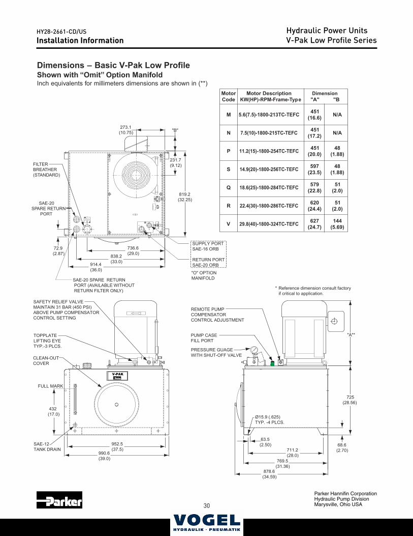
* Reference dimension consult factory if critical to application.
SAE-16 ORB
RETURN PORTSAE-20 ORB
"O" OPTIONMANIFOLD
819.2(32.25)
231.7(9.12)
"B" 273.1(10.75)
SAFETY RELIEF VALVEMAINTAIN 31 BAR (450 PSI)ABOVE PUMP COMPENSATORCONTROL SETTING
TOPPLATELIFTING EYETYP.-3 PLCS.
CLEAN-OUTCOVER
FULL MARK
SAE-12TANK DRAIN
952.5(37.5)
990.6(39.0)
REMOTE PUMPCOMPENSATORCONTROL ADJUSTMENT
PUMP CASEFILL PORT
PRESSURE GUAGEWITH SHUT-OFF VALVE
Ø15.9 (.625)TYP. -4 PLCS.
63.5(2.50)
711.2(28.0)
769.5(31.36)
878.6(34.59)
68.6(2.70)
"A"*
V-PAK
SAE-20SPARE RETURN PORT
725(28.56)
432(17.0)
"A"rotoM
edoCnoitpircseDrotoM
epyT-emarF-MPR-P)KW(H B"
M FCET-CT312-0081-5.6(7.5) 154)6.61( A/N
N FCET-CT512-0081-7.5(10) 154)2.71( A/N
P FCET-CT452-0081-11.2(15) 154)0.02(
84)88.1(
S FCET-CT652-0081-14.9(20) 795)5.32(
84)88.1(
Q FCET-CT482-0081-18.6(25) 975)8.22(
15)0.2(
R FCET-CT682-0081-22.4(30) 026)4.42(
15)0.2(
V FCET-CT423-0081-29.8(40) 726)7.42(
441)96.5(
Dimension
Dimensions – Basic V-Pak Low ProfileShown with “Omit” Option ManifoldInch equivalents for millimeters dimensions are shown in (**)
Technical Information
Hydraulic Power UnitsV-Pak Low Profile SeriesInstallation Information
30 31
Parker Hannifin CorporationHydraulic Pump DivisionMarysville, Ohio USA
HY28-2661-CD/US
Technical InformationHydraulic Power UnitsV-Pak Low Profile Series
Catalog HY13-1552-002/US,EUVolume ControlLow Profile Power UnitsSeries V-Paks
Parker Hannifin CorporationHydraulic Pump DivisionMarysville, Ohio USA
7
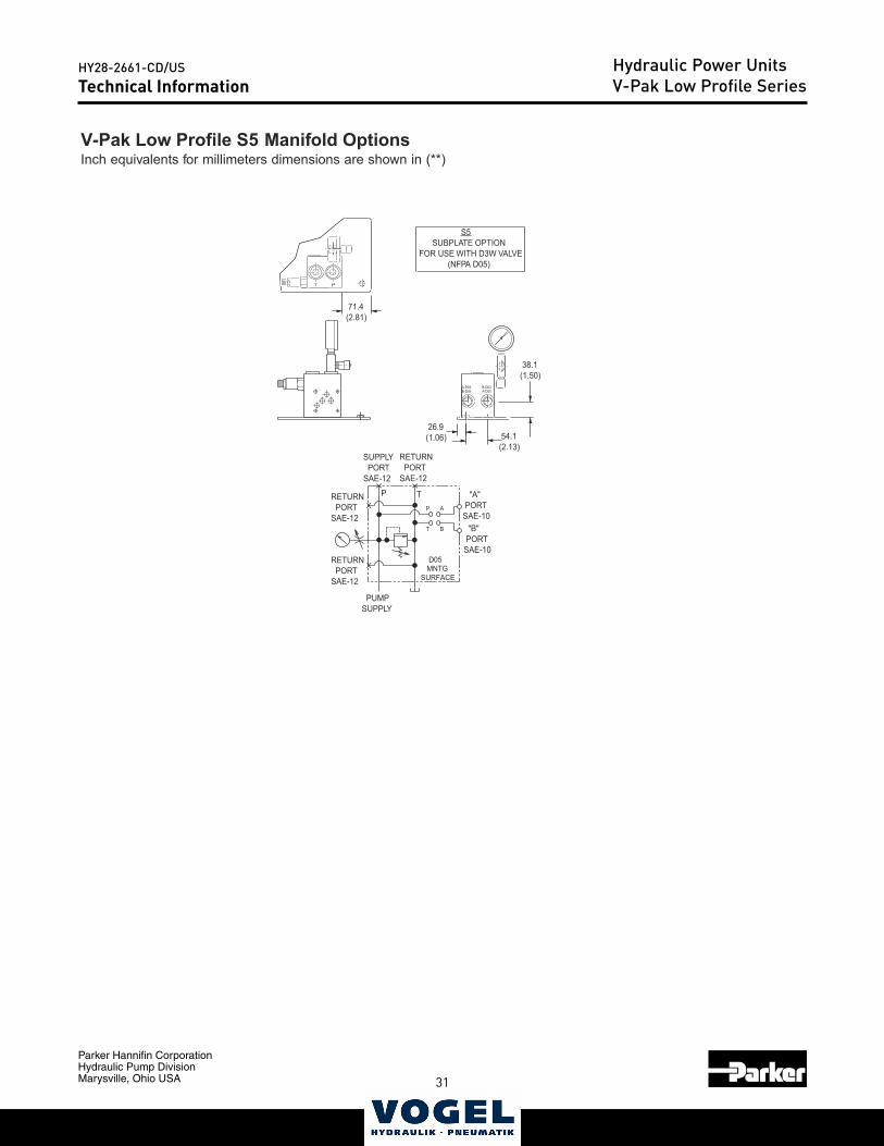
Technical Information
V-Pak Low Profile S5 Manifold OptionsInch equivalents for millimeters dimensions are shown in (**)
A-D05B-D03
B-D05A-D03
71.4(2.81)
38.1(1.50)
54.1(2.13)
26.9(1.06)
S5 SUBPLATE OPTIONFOR USE WITH D3W VALVE (NFPA D05)
XTP
XX
B
A
T
X
P
SUPPLY PORTSAE-12
RETURN PORTSAE-12
RETURN PORTSAE-12
RETURN PORTSAE-12
"A" PORTSAE-10 "B" PORTSAE-10
PUMPSUPPLY
D05 MNTGSURFACE
T P
32
Parker Hannifin CorporationHydraulic Pump DivisionMarysville, Ohio USA
HY28-2661-CD/US
33
Hydraulic Power UnitsV-Pak Low Profile SeriesTechnical Information
Catalog HY13-1552-002/US,EUVolume ControlLow Profile Power UnitsSeries V-Paks
Parker Hannifin CorporationHydraulic Pump DivisionMarysville, Ohio USA
8
T P
A
AB
B
Y
G
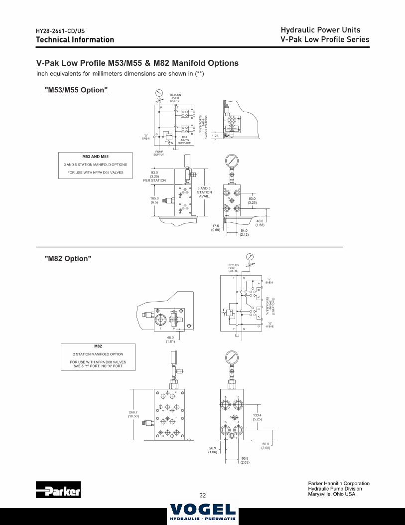
266.7(10.50)
46.0(1.81)
26.9(1.06)
66.8(2.63)
50.8(2.00)
133.4(5.25)
-16
SA
E(2
STA
TIO
NS
)
AB
X
PORTSAE-16
AB
TT
P
Y
"Y"SAE-8
G
"G"-6 SAE
P
"A"&
"B"P
OR
TSRETURN
M82
2 STATION MANIFOLD OPTION
FOR USE WITH NFPA D08 VALVESSAE-8 "Y" PORT, NO "X" PORT
3 AND 5 STATION
AVAIL.
83.0(3.25)
PER STATION
165.0(6.5)
83.0(3.25)
40.0(1.56)
54.0(2.12)
17.5(0.69)
1.25SAE-6
"G" G B
A
TP
G
B
B A
A
TP
X
3 A
ND
5 S
TATI
ON
SS
AE
-8"A
"&"B
"PO
RTS
SURFACEMNTGD05
SAE-12PORT
RETURN
B
A
SUPPLYPUMP
M53 AND M55
3 AND 5 STATION MANIFOLD OPTIONS
FOR USE WITH NFPA D05 VALVES
Technical Information
V-Pak Low Profile M53/M55 & M82 Manifold OptionsInch equivalents for millimeters dimensions are shown in (**)
"M53/M55 Option"
"M82 Option"
32 33
Parker Hannifin CorporationHydraulic Pump DivisionMarysville, Ohio USA
HY28-2661-CD/US Hydraulic Power UnitsV-Pak Low Profile SeriesTechnical Information
Catalog HY13-1552-002/US,EUVolume ControlLow Profile Power UnitsSeries V-Paks
Parker Hannifin CorporationHydraulic Pump DivisionMarysville, Ohio USA
9
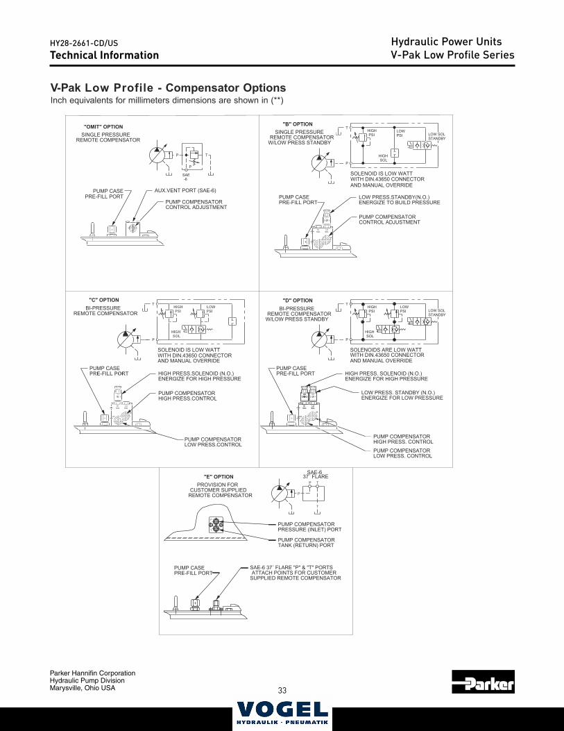
Technical Information
V-Pak Low Profile - Compensator OptionsInch equivalents for millimeters dimensions are shown in (**)
PRE-FILL PORTPUMP CASE
PRE-FILL PORTPUMP CASE
HI
PRE-FILL PORTPUMP CASE
LO
SOLLO
SOLHI
PRE-FILL PORTPUMP CASEPRE-FILL PORT
PUMP CASE AUX.VENT PORT (SAE-6)
-6SAE
PP
AND MANUAL OVERRIDEWITH DIN.43650 CONNECTORSOLENOIDS ARE LOW WATT
SOLHIGH
PSIHIGH
STANDBYLOW SOL
T
P
PSILOW
SOLHIGH
PSIHIGH
T
P
PSILOW
AND MANUAL OVERRIDEWITH DIN.43650 CONNECTORSOLENOID IS LOW WATT
SUPPLIED REMOTE COMPENSATORATTACH POINTS FOR CUSTOMER
SAE-6 37˚ FLARE "P" & "T" PORTS
TANK (RETURN) PORTPUMP COMPENSATOR
PRESSURE (INLET) PORTPUMP COMPENSATOR
37˚ FLARESAE-6
P T
T
P
AND MANUAL OVERRIDEWITH DIN.43650 CONNECTORSOLENOID IS LOW WATT
TP
REMOTE COMPENSATORCUSTOMER SUPPLIED
PROVISION FOR"E" OPTION
SOLHIGH
PSIHIGH
STANDBYLOW SOL
T
PSILOW
W/LOW PRESS STANDBYREMOTE COMPENSATOR
BI-PRESSURE"D" OPTION
REMOTE COMPENSATORBI-PRESSURE
"C" OPTION
ENERGIZE FOR LOW PRESSURELOW PRESS. STANDBY (N.O.)
HIGH PRESS. CONTROLPUMP COMPENSATOR
LOW PRESS. CONTROLPUMP COMPENSATOR
ENERGIZE FOR HIGH PRESSUREHIGH PRESS. SOLENOID (N.O.)
SOLLO
SOLHI
LO
HI
LOW PRESS.CONTROLPUMP COMPENSATOR
ENERGIZE FOR HIGH PRESSUREHIGH PRESS.SOLENOID (N.O.)
HIGH PRESS.CONTROLPUMP COMPENSATOR
ENERGIZE TO BUILD PRESSURELOW PRESS.STANDBY(N.O.)
CONTROL ADJUSTMENTPUMP COMPENSATOR
CONTROL ADJUSTMENTPUMP COMPENSATOR
W/LOW PRESS STANDBYREMOTE COMPENSATOR
SINGLE PRESSURE"B" OPTION
REMOTE COMPENSATORSINGLE PRESSURE"OMIT" OPTION
SOLLO
SOLHI
LOHI
T
P
34
Parker Hannifin CorporationHydraulic Pump DivisionMarysville, Ohio USA
HY28-2661-CD/US
35
Hydraulic Power UnitsV-Pak Low Profile SeriesTechnical Information
Catalog HY13-1552-002/US,EUVolume ControlLow Profile Power UnitsSeries V-Paks
Parker Hannifin CorporationHydraulic Pump DivisionMarysville, Ohio USA
10
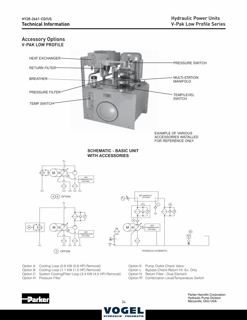
PRESSURE SWITCH
TEMP/LEVELSWITCH
MULTI-STATIONMANIFOLD
RETURN FILTER
HEAT EXCHANGER
PRESSURE FILTER
TEMP. SWITCH
EXAMPLE OF VARIOUSACCESSORIES INSTALLEDFOR REFERENCE ONLY
Accessory Options
SCHEMATIC - BASIC UNITWITH ACCESSORIES
BREATHER
N
M
HYDRAULIC SCHEMATIC
T
R*
L
K
H
P
SEE MANIFOLDOPTIONS
SEECOMPENSATOR
OPTIONS
XSAE-12
M
A B OPTION
M
C OPTION
M
SEECOMPENSATOR
OPTIONS
SEECOMPENSATOR
OPTIONS
Option A Cooling Loop (0.6 KW (0.8 HP) Removal)Option B Cooling Loop (1.1 KW (1.5 HP) Removal)Option C System Cooling/Filter Loop (3.4 KW (4.5 HP) Removal)Option H Pressure Filter
Option K Pump Outlet Check ValveOption L Bypass Check-Return Ht. Ex. OnlyOption N Return Filter - Dual ElementOption R* Combination Level/Temperature Switch
Accessory OptionsV-PAK LOW PROFILE
34 35
Parker Hannifin CorporationHydraulic Pump DivisionMarysville, Ohio USA
HY28-2661-CD/US Hydraulic Power UnitsV-Pak Low Profile SeriesTechnical Information
Catalog HY13-1552-002/US,EUVolume ControlLow Profile Power UnitsSeries V-Paks
Parker Hannifin CorporationHydraulic Pump DivisionMarysville, Ohio USA
11
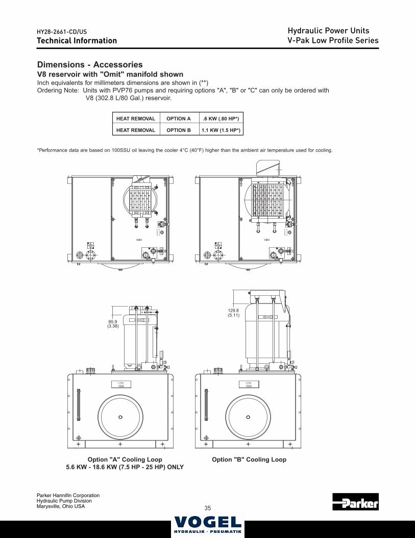
LAVOMERTAEH ANOITPO )*PH08.(WK6.
LAVOMERTAEH BNOITPO )*PH5.1(WK1.1
Dimensions - AccessoriesV8 reservoir with "Omit" manifold shownInch equivalents for millimeters dimensions are shown in (**)Ordering Note: Units with PVP76 pumps and requiring options "A", "B" or "C" can only be ordered with
V8 (302.8 L/80 Gal.) reservoir.
Technical Information
Option "A" Cooling Loop5.6 KW - 18.6 KW (7.5 HP - 25 HP) ONLY
Option "B" Cooling Loop
*Performance data are based on 100SSU oil leaving the cooler 4°C (40°F) higher than the ambient air temperature used for cooling.
PU
MP
PR
IME
V-PAK
PU
MP
CO
MP
EN
SA
TOR
CO
NTR
OL
SAFETY RELIEFDO NOT ADJUST
T
P
PU
MP
PR
IME
V-PAK
PU
MP
CO
MP
EN
SA
TOR
CO
NTR
OL
SAFETY RELIEFDO NOT ADJUST
T
P
(3.38)85.9
(5.11)129.8
36
Parker Hannifin CorporationHydraulic Pump DivisionMarysville, Ohio USA
HY28-2661-CD/US
37
Hydraulic Power UnitsV-Pak Low Profile SeriesTechnical Information
Catalog HY13-1552-002/US,EUVolume ControlLow Profile Power UnitsSeries V-Paks
Parker Hannifin CorporationHydraulic Pump DivisionMarysville, Ohio USA
12
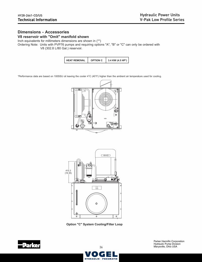
LAVOMERTAEH CNOITPO )*PH5.4(WK4.3
*Performance data are based on 100SSU oil leaving the cooler 4°C (40°F) higher than the ambient air temperature used for cooling.
Option "C" System Cooling/Filter Loop
Dimensions - AccessoriesV8 reservoir with "Omit" manifold shownInch equivalents for millimeters dimensions are shown in (**)Ordering Note: Units with PVP76 pumps and requiring options "A", "B" or "C" can only be ordered with
V8 (302.8 L/80 Gal.) reservoir.
Technical Information
P
T
SAFETY RELIEFDO NOT ADJUST
PU
MP
CO
MP
EN
SA
TOR
CO
NTR
OL
V-PAK
PU
MP
PR
IME
IN
OUT
(16.35)415.3
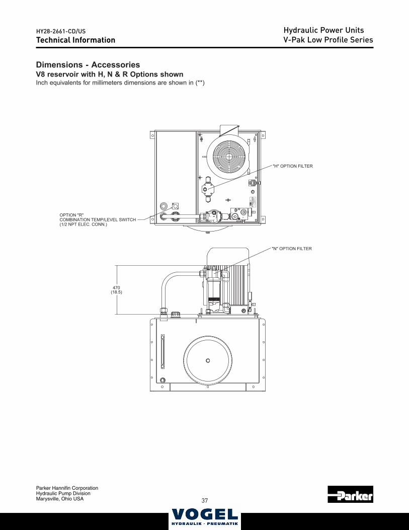
36 37
Parker Hannifin CorporationHydraulic Pump DivisionMarysville, Ohio USA
HY28-2661-CD/US Hydraulic Power UnitsV-Pak Low Profile SeriesTechnical Information
Catalog HY13-1552-002/US,EUVolume ControlLow Profile Power UnitsSeries V-Paks
Parker Hannifin CorporationHydraulic Pump DivisionMarysville, Ohio USA
13
Technical Information
Dimensions - AccessoriesV8 reservoir with H, N & R Options shownInch equivalents for millimeters dimensions are shown in (**)
PU
MP
CO
MP
EN
SA
TOR
CO
NTR
OL
PU
MP
FLO
W
PR
ES
SU
RE
MA
X
HY
DR
AU
LIC
PU
MP
/MO
TOR
DIV
ISIO
NO
TSE
GO
MIC
H 4
9078
US
A
S/N
PS
I
GP
M
GA
L
Sys
tem
sFl
uidp
ower
MO
DE
L N
UM
BE
R
TAN
K
P
DO NOT ADJUSTSAFETY RELIEF
T
"N" OPTION FILTER
"H" OPTION FILTER
(1/2 NPT ELEC. CONN.)COMBINATION TEMP/LEVEL SWITCHOPTION "R"
470(18.5)
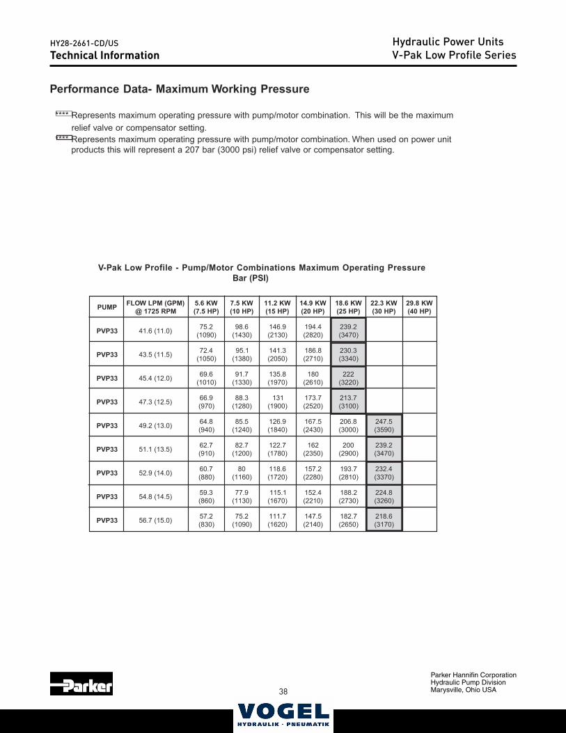
38
Parker Hannifin CorporationHydraulic Pump DivisionMarysville, Ohio USA
HY28-2661-CD/US
39
Hydraulic Power UnitsV-Pak Low Profile SeriesTechnical Information
Catalog HY13-1552-002/US,EUVolume ControlLow Profile Power UnitsSeries V-Paks
Parker Hannifin CorporationHydraulic Pump DivisionMarysville, Ohio USA
14
Technical Information
Performance Data- Maximum Working Pressure
**** Represents maximum operating pressure with pump/motor combination. This will be the maximum relief valve or compensator setting. **** Represents maximum operating pressure with pump/motor combination. When used on power unit products this will represent a 207 bar (3000 psi) relief valve or compensator setting.
V-Pak Low Profile - Pump/Motor Combinations Maximum Operating PressureBar (PSI)
PMUP )MPG(MPLWOLFMPR5271@
WK6.5)PH5.7(
WK5.7)PH01(
WK2.11)PH51(
WK9.41)PH02(
WK6.81)PH52(
WK3.22)PH03(
WK8.92)PH04(
33PVP )0.11(6.14 2.57)0901(
6.89)0341(
9.641)0312(
4.491)0282(
2.932)0743(
33PVP )5.11(5.34 4.27)0501(
1.59)0831(
3.141)0502(
8.681)0172(
3.032)0433(
33PVP )0.21(4.54 6.96)0101(
7.19)0331(
8.531)0791(
081)0162(
222)0223(
33PVP )5.21(3.74 9.66)079(
3.88)0821(
131)0091(
7.371)0252(
7.312)0013(
33PVP )0.31(2.94 8.46)049(
5.58)0421(
9.621)0481(
5.761)0342(
8.602)0003(
5.742)0953(
33PVP )5.31(1.15 7.26)019(
7.28)0021(
7.221)0871(
261)0532(
002)0092(
2.932)0743(
33PVP )0.41(9.25 7.06)088(
08)0611(
6.811)0271(
2.751)0822(
7.391)0182(
4.232)0733(
33PVP )5.41(8.45 3.95)068(
9.77)0311(
1.511)0761(
4.251)0122(
2.881)0372(
8.422)0623(
33PVP )0.51(7.65 2.75)038(
2.57)0901(
7.111)0261(
5.741)0412(
7.281)0562(
6.812)0713(
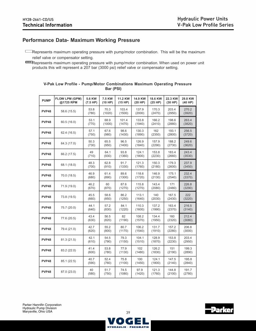
38 39
Parker Hannifin CorporationHydraulic Pump DivisionMarysville, Ohio USA
HY28-2661-CD/US Hydraulic Power UnitsV-Pak Low Profile SeriesTechnical InformationCatalog HY13-1552-002/US,EU
Volume ControlLow Profile Power UnitsSeries V-Paks
Parker Hannifin CorporationHydraulic Pump DivisionMarysville, Ohio USA
15
Performance Data- Maximum Working Pressure
**** Represents maximum operating pressure with pump/motor combination. This will be the maximum relief valve or compensator setting. **** Represents maximum operating pressure with pump/motor combination. When used on power unit products this will represent a 207 bar (3000 psi) relief valve or compensator setting.
V-Pak Low Profile - Pump/Motor Combinations Maximum Operating PressureBar (PSI)
Technical Information
PMUP )MPG(MPLWOLFMPR5271@
WK6.5)PH5.7(
WK5.7)PH01(
WK2.11)PH51(
WK9.41)PH02(
WK6.81)PH52(
WK3.22)PH03(
WK8.92)PH04(
84PVP )5.51(6.85 8.35)087(
3.07)0201(
4.301)0051(
9.731)0002(
3.071)0742(
4.302)0592(
2.072)0293(
84PVP )0.61(5.06 1.35)077(
9.86)0001(
4.101)0741(
8.331)0491(
2.661)0142(
6.891)0882(
4.362)0283(
84PVP )5.61(4.26 1.75)057(
6.76)089(
6.89)0341(
3.031)0981(
261)0532(
1.391)0082(
5.652)0273(
84PVP )0.71(3.46 3.05)037(
5.56)059(
5.69)0041(
9.621)0481(
9.751)0922(
2.881)0372(
6.942)0263(
84PVP )5.71(2.66 94)017(
1.46)039(
8.39)0631(
1.421)0081(
8.351)0322(
4.381)0662(
4.342)0353(
84PVP )0.81(1.86 3.84)007(
8.26)019(
7.19)0331(
3.121)0671(
3.051)0812(
3.971)0062(
9.732)0543(
84PVP )5.81(0.07 9.64)086(
4.16)098(
6.98)0031(
6.811)0271(
9.641)0312(
1.571)0452(
4.232)0733(
84PVP )0.91(9.17 2.64)076(
06)078(
6.78)0721(
8.511)0721(
4.341)0802(
171)0842(
8.622)0923(
84PVP )5.91(8.37 5.54)066(
6.85)058(
2.68)0521(
1.311)0461(
041)0302(
5.761)0342(
222)0223(
84PVP )0.02(7.57 1.44)046(
2.75)038(
1.48)0221(
3.011)0061(
2.731)0991(
4.361)0732(
5.612)0413(
84PVP )5.02(6.77 4.34)036(
5.65)028(
28)0911(
2.801)0751(
4.431)0591(
061)0232(
4.212)0803(
84PVP )0.12(4.97 7.24)026(
2.55)008(
7.08)0711(
2.601)0451(
7.131)0191(
2.751)0822(
8.602)0003(
84PVP )5.12(3.18 1.24)016(
5.45)097(
3.97)0511(
1.401)0151(
9.821)0781(
8.351)0322(
4.302)0592(
84PVP )0.22(2.38 4.14)006(
8.35)087(
9.77)0311(
201)0841(
2.621)0381(
151)0912(
3.991)0982(
84PVP )5.22(1.58 7.04)095(
4.25)067(
8.57)0011(
001)0541(
1.421)0081(
5.741)0412(
8.591)0482(
84PVP )0.32(0.78 04)085(
7.15)057(
5.47)0801(
9.79)0241(
3.121)0671(
8.441)0012(
7.191)0872(
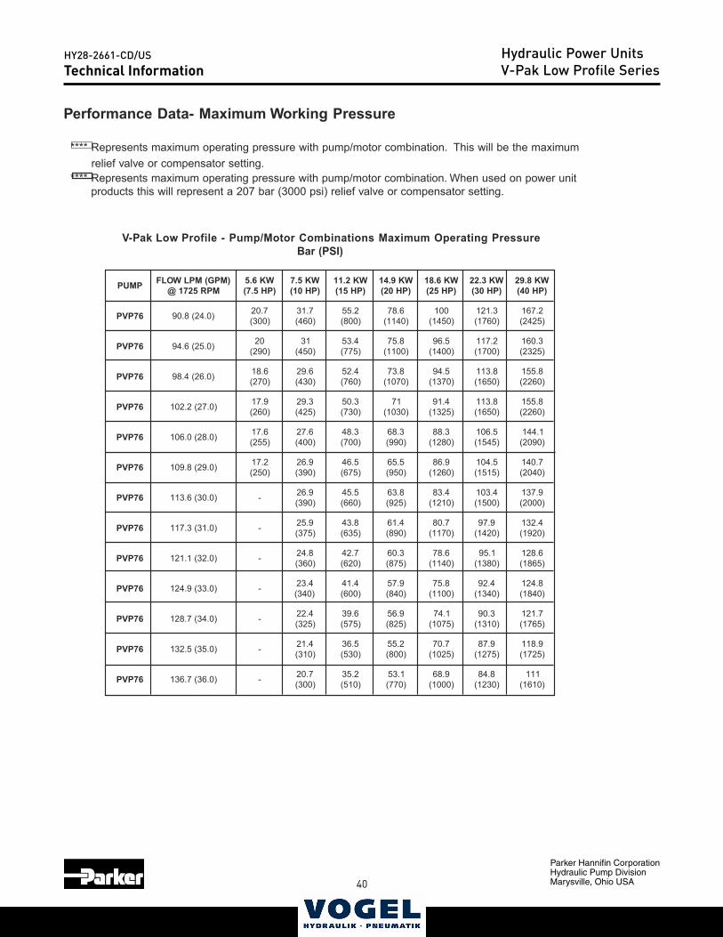
40
Parker Hannifin CorporationHydraulic Pump DivisionMarysville, Ohio USA
HY28-2661-CD/US
41
Hydraulic Power UnitsV-Pak Low Profile SeriesTechnical Information
Catalog HY13-1552-002/US,EUVolume ControlLow Profile Power UnitsSeries V-Paks
Parker Hannifin CorporationHydraulic Pump DivisionMarysville, Ohio USA
16
Performance Data- Maximum Working Pressure
**** Represents maximum operating pressure with pump/motor combination. This will be the maximum relief valve or compensator setting. **** Represents maximum operating pressure with pump/motor combination. When used on power unit products this will represent a 207 bar (3000 psi) relief valve or compensator setting.
V-Pak Low Profile - Pump/Motor Combinations Maximum Operating PressureBar (PSI)
Technical Information
PMUP )MPG(MPLWOLFMPR5271@
WK6.5)PH5.7(
WK5.7)PH01(
WK2.11)PH51(
WK9.41)PH02(
WK6.81)PH52(
WK3.22)PH03(
WK8.92)PH04(
67PVP )0.42(8.09 7.02)003(
7.13)064(
2.55)008(
6.87)0411(
001)0541(
3.121)0671(
2.761)5242(
67PVP )0.52(6.49 02)092(
13)054(
4.35)577(
8.57)0011(
5.69)0041(
2.711)0071(
3.061)5232(
67PVP )0.62(4.89 6.81)072(
6.92)034(
4.25)067(
8.37)0701(
5.49)0731(
8.311)0561(
8.551)0622(
67PVP )0.72(2.201 9.71)062(
3.92)524(
3.05)037(
17)0301(
4.19)5231(
8.311)0561(
8.551)0622(
67PVP )0.82(0.601 6.71)552(
6.72)004(
3.84)007(
3.86)099(
3.88)0821(
5.601)5451(
1.441)0902(
67PVP )0.92(8.901 2.71)052(
9.62)093(
5.64)576(
5.56)059(
9.68)0621(
5.401)5151(
7.041)0402(
67PVP )0.03(6.311 - 9.62)093(
5.54)066(
8.36)529(
4.38)0121(
4.301)0051(
9.731)0002(
67PVP )0.13(3.711 - 9.52)573(
8.34)536(
4.16)098(
7.08)0711(
9.79)0241(
4.231)0291(
67PVP )0.23(1.121 - 8.42)063(
7.24)026(
3.06)578(
6.87)0411(
1.59)0831(
6.821)5681(
67PVP )0.33(9.421 - 4.32)043(
4.14)006(
9.75)048(
8.57)0011(
4.29)0431(
8.421)0481(
67PVP )0.43(7.821 - 4.22)523(
6.93)575(
9.65)528(
1.47)5701(
3.09)0131(
7.121)5671(
67PVP )0.53(5.231 - 4.12)013(
5.63)035(
2.55)008(
7.07)5201(
9.78)5721(
9.811)5271(
67PVP )0.63(7.631 - 7.02)003(
2.53)015(
1.35)077(
9.86)0001(
8.48)0321(
111)0161(
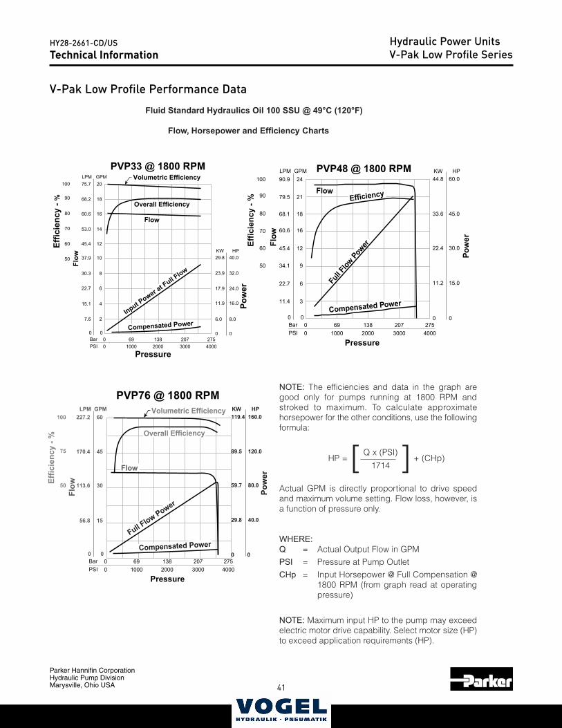
40 41
Parker Hannifin CorporationHydraulic Pump DivisionMarysville, Ohio USA
HY28-2661-CD/US Hydraulic Power UnitsV-Pak Low Profile SeriesTechnical Information
Catalog HY13-1552-002/US,EUVolume ControlLow Profile Power UnitsSeries V-Paks
Parker Hannifin CorporationHydraulic Pump DivisionMarysville, Ohio USA
17
Technical Information
Performance Data
NOTE: The efficiencies and data in the graph aregood only for pumps running at 1800 RPM andstroked to maximum. To calculate approximatehorsepower for the other conditions, use the followingformula:
HP =[ Q x (PSI) ] + (CHp)1714
Actual GPM is directly proportional to drive speedand maximum volume setting. Flow loss, however, isa function of pressure only.
WHERE:Q = Actual Output Flow in GPM
PSI = Pressure at Pump Outlet
CHp = Input Horsepower @ Full Compensation @1800 RPM (from graph read at operatingpressure)
NOTE: Maximum input HP to the pump may exceedelectric motor drive capability. Select motor size (HP)to exceed application requirements (HP).
Fluid Standard Hydraulics Oil 100 SSU @ 49°C (120°F)
Flow, Horsepower and Efficiency Charts
30
45
60100
75
50
FlowEf
ficie
ncy
- %
Pow
er
PVP76 @ 1800 RPM
0
15
113.6
170.4
227.2
0
56.8
00
BarPSI
691000
1382000
2073000
2754000
Pressure
GPMLPM
0
29.8
59.7
0
40.0
80.0
89.5
119.4
120.0
160.0HPKW
Flow
Overall Efficiency
Volumetric Efficiency
Compensated PowerFull F
low Power
8
10
12
14
16
18
20100
90
80
70
60
50
Flow
Effic
ienc
y - %
Pow
er
PVP33 @ 1800 RPM
0
4
2
6
30.3
37.9
45.4
53.0
60.6
68.2
75.7
0
15.1
7.6
22.7
00
BarPSI
691000
1382000
2073000
2754000
Pressure
GPMLPM
0
6.0
11.9
17.9
23.9
29.8
0
8.0
16.0
24.0
32.0
40.0HPKW
Volumetric Efficiency
Overall Efficiency
Flow
Input Power a
t Full F
low
Compensated Power
12
16
18
21
24100
90
80
70
60
50Fl
ow
Effic
ienc
y - %
Pow
er
PVP48 @ 1800 RPM
0
6
3
9
45.4
60.6
68.1
79.5
90.9
0
22.7
11.4
34.1
00
BarPSI
691000
1382000
2073000
2754000
Pressure
GPMLPM
0
11.2
22.4
0
15.0
30.0
33.6
44.8
45.0
60.0HPKW
FlowEfficiency
Compensated Power
Full F
low Pow
er
V-Pak Low Profile Performance Data
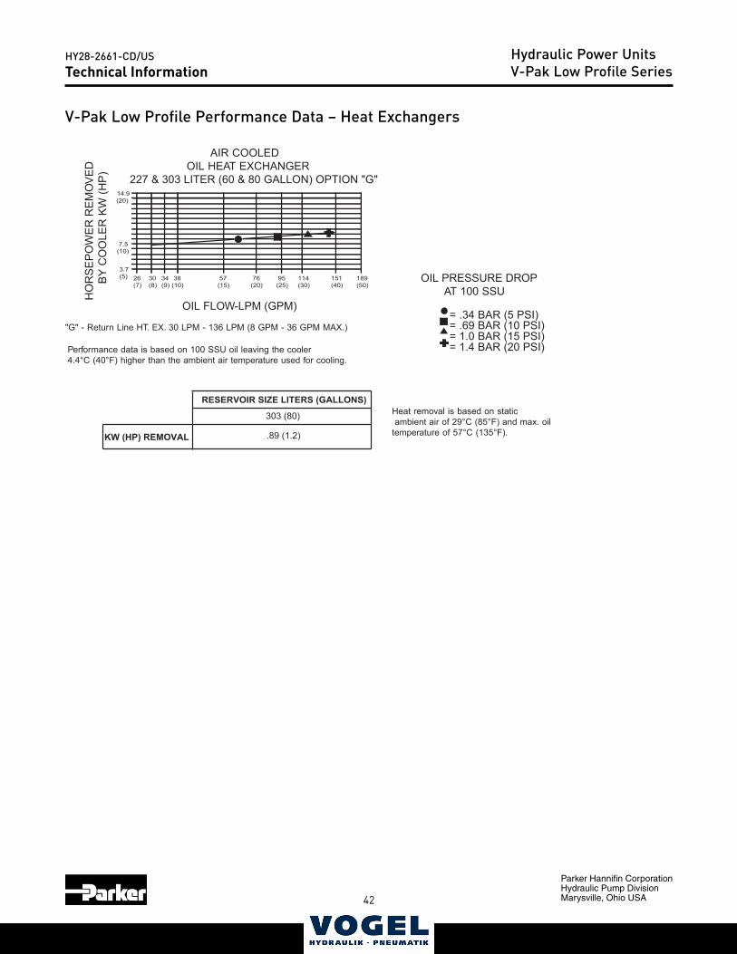
42
Parker Hannifin CorporationHydraulic Pump DivisionMarysville, Ohio USA
HY28-2661-CD/US
43
Hydraulic Power UnitsV-Pak Low Profile SeriesTechnical Information
Catalog HY13-1552-002/US,EUVolume ControlLow Profile Power UnitsSeries V-Paks
Parker Hannifin CorporationHydraulic Pump DivisionMarysville, Ohio USA
18
14.9(20)
7.5(10)
189(50)
151(40)
114(30)
95(25)
76(20)
57(15)
38(10)
34(9)
30(8)
26(7)
3.7(5)
RESERVOIR SIZE LITERS (GALLONS)
.89 (1.2)
303 (80)
KW (HP) REMOVAL
Technical Information
"G" - Return Line HT. EX. 30 LPM - 136 LPM (8 GPM - 36 GPM MAX.)
Performance data is based on 100 SSU oil leaving the cooler4.4°C (40°F) higher than the ambient air temperature used for cooling.
Heat removal is based on static ambient air of 29°C (85°F) and max. oiltemperature of 57°C (135°F).
OIL FLOW-LPM (GPM)
HO
RSE
POW
ER R
EMO
VED
B
Y C
OO
LER
KW
(HP
)
AIR COOLED OIL HEAT EXCHANGER227 & 303 LITER (60 & 80 GALLON) OPTION "G"
= .34 BAR (5 PSI)= .69 BAR (10 PSI)= 1.0 BAR (15 PSI)= 1.4 BAR (20 PSI)
OIL PRESSURE DROP AT 100 SSU
V-Pak Low Profile Performance Data – Heat Exchangers
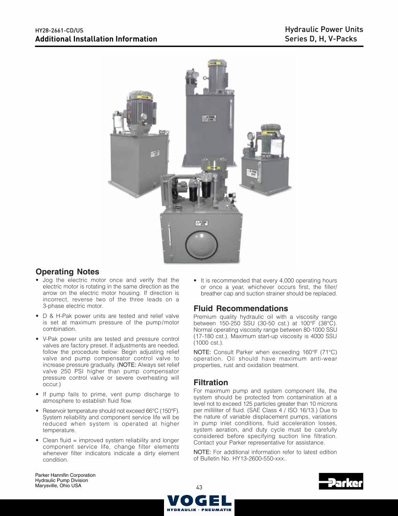
42 43
Parker Hannifin CorporationHydraulic Pump DivisionMarysville, Ohio USA
HY28-2661-CD/USCatalog HY28-2661-CD/US
Volume ControlVertical Power Units
Parker Hannifin CorporationHydraulic Pump DivisionMaryville, Ohio USA
28
Installation Information Series D, H, V-Paks
Operating Notes• Jog the electric motor once and verify that the
electric motor is rotating in the same direction as thearrow on the electric motor housing. If direction isincorrect, reverse two of the three leads on a3-phase electric motor.
• D & H-Pak power units are tested and relief valveis set at maximum pressure of the pump/motorcombination.
• V-Pak power units are tested and pressure controlvalves are factory preset. If adjustments are needed,follow the procedure below: Begin adjusting reliefvalve and pump compensator control valve toincrease pressure gradually. (NOTE: Always set reliefvalve 250 PSI higher than pump compensatorpressure control valve or severe overheating willoccur.)
• If pump fails to prime, vent pump discharge toatmosphere to establish fluid flow.
• Reservoir temperature should not exceed 66°C (150°F).System reliability and component service life will bereduced when system is operated at highertemperature.
• Clean fluid = improved system reliability and longercomponent service life, change filter elementswhenever filter indicators indicate a dirty elementcondition.
• It is recommended that every 4,000 operating hoursor once a year, whichever occurs first, the filler/breather cap and suction strainer should be replaced.
Fluid RecommendationsPremium quality hydraulic oil with a viscosity rangebetween 150-250 SSU (30-50 cst.) at 100°F (38°C).Normal operating viscosity range between 80-1000 SSU(17-180 cst.). Maximum start-up viscosity is 4000 SSU(1000 cst.).
NOTE: Consult Parker when exceeding 160°F (71°C)operation. Oil should have maximum anti-wearproperties, rust and oxidation treatment.
FiltrationFor maximum pump and system component life, thesystem should be protected from contamination at alevel not to exceed 125 particles greater than 10 micronsper milliliter of fluid. (SAE Class 4 / ISO 16/13.) Due tothe nature of variable displacement pumps, variationsin pump inlet conditions, fluid acceleration losses,system aeration, and duty cycle must be carefullyconsidered before specifying suction line filtration.Contact your Parker representative for assistance.
NOTE: For additional information refer to latest editionof Bulletin No. HY13-2600-550-xxx..
Additional Installation InformationHydraulic Power UnitsSeries D, H, V-Packs
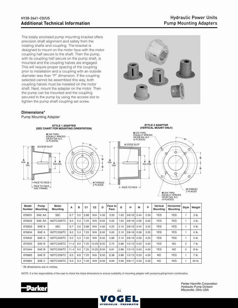
44
Parker Hannifin CorporationHydraulic Pump DivisionMarysville, Ohio USA
HY28-2661-CD/US
45
Catalog HY28-2661-CD/USVolume ControlVertical Power Units
Parker Hannifin CorporationHydraulic Pump DivisionMaryville, Ohio USA
29
Model Pump Motor A B C1 C2 D Face to G H M P Vertical Horizontal Style WeightNumber Mounting Mounting Face Mounting Mounting
876631 SAE AA 56C 6.7 5.0 5.88 N/A 4.50 3.50 1.63 3/8-16 0.44 2.00 YES YES 1 3 lb.
876632 SAE AA 182TC/256TC 9.0 5.3 7.25 N/A 8.50 5.00 1.63 3/8-16 0.56 2.00 YES YES 1 4 lb.
876633 SAE A 56C 6.7 5.0 5.88 N/A 4.50 4.25 2.10 3/8-16 0.44 3.25 YES YES 1 4 lb.
876634 SAE A 182TC/256TC 9.0 5.3 7.25 N/A 8.50 5.00 2.10 3/8-16 0.56 3.25 YES YES 1 4 lb.
876635 SAE A 182TC/256TC 9.0 5.3 7.25 N/A 8.50 5.88 2.10 3/8-16 0.56 3.25 YES YES 1 5 lb.
875343 SAE B 182TC/256TC 11.4 9.0 7.25 10.25 8.50 5.75 2.88 1/2-13 0.53 4.00 YES NO 2 7 lb.
875344 SAE B 182TC/256TC 11.4 9.0 7.25 10.25 8.50 6.81 2.88 1/2-13 0.53 4.00 YES NO 2 8 lb.
876683 SAE B 182TC/256TC 9.0 8.8 7.25 N/A 8.50 6.38 2.88 1/2-13 0.53 4.00 NO YES 1 7 lb.
876684 SAE C 182TC/256TC 9.0 9.3 7.25 N/A 8.50 6.69 3.56 5/8-11 0.53 5.00 NO YES 1 20 lb.
* All dimensions are in inches.
NOTE: It is the responsibility of the user to check the listed dimensions to ensure suitability of mounting adapter with pump/coupling/motor combination.
Technical Information Pump Mounting Adapters
The totally enclosed pump mounting bracket offersprecision shaft alignment and safety from therotating shafts and coupling. The bracket isdesigned to mount on the motor face with the motorcoupling half secure to the shaft. Then the pump,with its coupling half secure on the pump shaft, ismounted and the coupling halves are engaged.This will require proper spacing of the couplingprior to installation and a coupling with an outsidediameter less than “P” dimension. If the couplingselected cannot be assembled this way, bothcoupling halves must be installed on the motorshaft. Next, mount the adapter on the motor. Thenthe pump can be mounted and the couplingsecured to the pump by using the access slot totighten the pump shaft coupling set screw.
Dimensions*Pump Mounting Adapter
M DIA THRUEQUALLY SPACEDON C1 DIA. B.C.(4 PLACES)
H THREAD2 PLACES
ACCESS SLOT
STYLE 1 ADAPTER(SEE CHART FOR MOUNTING ORIENTATION)
STYLE 2 ADAPTER(VERTICAL MOUNT ONLY)
45
DDIA.
ADIA. P
DIA.G
G
M DIA THRUEQUALLY SPACEDON C2 DIA. B.C.(4 PLACES)
M DIA THRUEQUALLY SPACEDON C1 DIA. B.C.(4 PLACES)
H THREAD2 PLACES
45
G
G
FACE TO FACE
BDIA.
FACE TO FACE(56C FRAME)
ACCESS SLOT
DDIA.
ADIA. P
DIA.
FACE TO FACE
BDIA.
Additional Technical InformationHydraulic Power Units
Pump Mounting Adapters
44 45
Parker Hannifin CorporationHydraulic Pump DivisionMarysville, Ohio USA
HY28-2661-CD/USCatalog HY28-2661-CD/US
Volume ControlVertical Power Units
Parker Hannifin CorporationHydraulic Pump DivisionMaryville, Ohio USA
30
Conversion Equations
Application Formulas
• 1 GPM at 1500 PSI = 1 HP (General Rule)
• 1 Gallon = 231 Cubic Inches (3.7854 Liters)
• 1 Gallon Oil = 7.08 Lbs.
• 1 bar = 14.5 PSI
• 25.4mm = 1 Inch
HP = GPM x PSI
1714 x Pump Efficiency
PSI = 1714 x Pump Efficiency x HP
GPM
GPM = 1714 x Pump Efficiency x HP
PSI
HP = Torque (in.-lbs.) x RPM
63025
Torque = HP x 63025
RPM
RPM = HP x 63025
Torque
Motor InformationAt 440V — 3-Phase Motor Draws 1.25 AMP/HPAt 220V — 3-Phase Motor Draws 2.5 AMP/HPAt 110V — Single Phase Motor Draws 10 AMP/HP
• 1 HP = 42.4 BTU/Min.
• 1 Gallon = 3.7854 Liters
Conversion EquationsHydraulic Power UnitsD, H and V-Pak Series
46
Parker Hannifin CorporationHydraulic Pump DivisionMarysville, Ohio USA
HY28-2661-CD/US
47
NotesHydraulic Power Units
46 47
Parker Hannifin CorporationHydraulic Pump DivisionMarysville, Ohio USA
HY28-2661-CD/US
Offer of Sale
The items described in this document and other documents and descriptions provided by Parker Hannifin Corporation, Hydraulics Group, and its authorized distributors (“Seller”) are hereby offered for sale at prices to be established by Seller. This offer and its acceptance by any customer (“Buyer”) shall be governed by all of the following Terms and Conditions. Buyer’s order for any item described in its document, when communicated to Seller verbally, or in writing, shall constitute acceptance of this offer. All goods or work described will be referred to as “Products”.
1. Terms and Conditions. Seller’s willingness to offer Products, or accept an order for Products, to or from Buyer is expressly conditioned on Buyer’s assent to these Terms and Conditions and to the terms and conditions found on-line at www.parker.com/saleterms/. Seller objects to any contrary or additional term or condition of Buyer’s order or any other document issued by Buyer.2. Price Adjustments; Payments. Prices stated on the reverse side or preceding pages of this document are valid for 30 days. After 30 days, Seller may change prices to reflect any increase in its costs resulting from state, federal or local legislation, price increases from its suppliers, or any change in the rate, charge, or classification of any carrier. The prices stated on the reverse or preceding pages of this document do not include any sales, use, or other taxes unless so stated specifically. Unless otherwise specified by Seller, all prices are F.O.B. Seller’s facility, and payment is due 30 days from the date of invoice. After 30 days, Buyer shall pay interest on any unpaid invoices at the rate of 1.5% per month or the maximum allowable rate under applicable law.3. Delivery Dates; Title and Risk; Shipment. All delivery dates are approximate and Seller shall not be responsible for any damages resulting from any delay. Regardless of the manner of shipment, title to any products and risk of loss or damage shall pass to Buyer upon tender to the carrier at Seller’s facility (i.e., when it’s on the truck, it’s yours). Unless otherwise stated, Seller may exercise its judgment in choosing the carrier and means of delivery. No deferment of shipment at Buyers’ request beyond the respective dates indicated will be made except on terms that will indemnify, defend and hold Seller harmless against all loss and additional expense. Buyer shall be responsible for any additional shipping charges incurred by Seller due to Buyer’s changes in shipping, product specifications or in accordance with Section 13, herein.4. Warranty. Seller warrants that the Products sold hereunder shall be free from defects in material or workmanship for a period of eighteen months from the date of delivery to Buyer. The prices charged for Seller’s products are based upon the exclusive limited warranty stated above, and upon the following disclaimer: DISCLAIMER OF WARRANTY: THIS WARRANTY COMPRISES THE SOLE AND ENTIRE WARRANTY PERTAINING TO PRODUCTS PROVIDED HEREUNDER. SELLER DISCLAIMS ALL OTHER WARRAN-TIES, EXPRESS AND IMPLIED, INCLUDING MERCHANTABILITY AND FITNESS FOR A PARTICULAR PURPOSE.5. Claims; Commencement of Actions. Buyer shall promptly inspect all Products upon delivery. No claims for shortages will be allowed unless reported to the Seller within 10 days of delivery. No other claims against Seller will be allowed unless asserted in writing within 60 days after delivery or, in the case of an alleged breach of warranty, within 30 days after the date within the warranty period on which the defect is or should have been discovered by Buyer. Any action based upon breach of this agreement or upon any other claim arising out of this sale (other than an action by Seller for any amount due to Seller from Buyer) must be commenced within thirteen months from the date of tender of delivery by Seller or, for a cause of action based upon an alleged breach of warranty, within thirteen months from the date within the warranty period on which the defect is or should have been discovered by Buyer.6. LIMITATION OF LIABILITY. UPON NOTIFICATION, SELLER WILL, AT ITS OPTION, REPAIR OR REPLACE A DEFECTIVE PRODUCT, OR REFUND THE PURCHASE PRICE. IN NO EVENT SHALL SELLER BE LIABLE TO BUYER FOR ANY SPECIAL, INDIRECT, INCIDENTAL OR CONSEQUENTIAL DAMAGES ARISING OUT OF, OR AS THE RESULT OF, THE SALE, DELIVERY, NON-DELIVERY, SERVICING, USE OR LOSS OF USE OF THE PRODUCTS OR ANY PART THEREOF, OR FOR ANY CHARGES OR EXPENSES OF ANY NATURE INCURRED WITHOUT SELLER’S WRITTEN CONSENT, EVEN IF SELLER HAS BEEN NEGLIGENT, WHETHER IN CONTRACT, TORT OR OTHER LEGAL THEORY. IN NO EVENT SHALL SELLER’S LIABILITY UNDER ANY CLAIM MADE BY BUYER EXCEED THE PURCHASE PRICE OF THE PRODUCTS.7. Contingencies. Seller shall not be liable for any default or delay in performance if caused by circumstances beyond the reasonable control of Seller.8. User Responsibility. The user, through its own analysis and testing, is solely responsible for making the final selection of the system and Product and assuring that all performance, endurance, maintenance, safety and warning requirements of the application are met. The user must analyze all aspects of the application and follow applicable industry standards and Product information. If Seller provides Product or system options, the user is responsible for determining that such data and specifications are suitable and sufficient for all applications and reasonably foreseeable uses of the Products or systems.9. Loss to Buyer’s Property. Any designs, tools, patterns, materials, drawings, confiden-tial information or equipment furnished by Buyer or any other items which become Buyer’s property, may be considered obsolete and may be destroyed by Seller after two consecutive years have elapsed without Buyer placing an order for the items which are manufactured using such property. Seller shall not be responsible for any loss or damage to such property while it is in Seller’s possession or control.10. Special Tooling. A tooling charge may be imposed for any special tooling, including without limitation, dies, fixtures, molds and patterns, acquired to manufacture Products. Such special tooling shall be and remain Seller’s property notwithstanding payment of any charges by Buyer. In no event will Buyer acquire any interest in apparatus belonging to Seller which is utilized in the manufacture of the Products, even if such apparatus has been specially converted or adapted for such manufacture and notwithstanding any charges paid by Buyer. Unless otherwise agreed, Seller shall have the right to alter, discard or otherwise dispose of any special tooling or other property in its sole discretion at any time.
11. Buyer’s Obligation; Rights of Seller. To secure payment of all sums due or otherwise, Seller shall retain a security interest in the goods delivered and this agreement shall be deemed a Security Agreement under the Uniform Commercial Code. Buyer authorizes Seller as its attorney to execute and file on Buyer’s behalf all documents Seller deems necessary to perfect its security interest. Seller shall have a security interest in, and lien upon, any property of Buyer in Seller’s possession as security for the payment of any amounts owed to Seller by Buyer.12. Improper Use and Indemnity. Buyer shall indemnify, defend, and hold Seller harmless from any claim, liability, damages, lawsuits, and costs (including attorney fees), whether for personal injury, property damage, patent, trademark or copyright infringement or any other claim, brought by or incurred by Buyer, Buyer’s employees, or any other person, arising out of: (a) improper selection, improper application or other misuse of Products purchased by Buyer from Seller; (b) any act or omission, negligent or otherwise, of Buyer; (c) Seller’s use of patterns, plans, drawings, or specifications furnished by Buyer to manufacture Product; or (d) Buyer’s failure to comply with these terms and conditions. Seller shall not indemnify Buyer under any circumstance except as otherwise provided.13. Cancellations and Changes. Orders shall not be subject to cancellation or change by Buyer for any reason, except with Seller’s written consent and upon terms that will indemnify, defend and hold Seller harmless against all direct, incidental and consequential loss or damage. Seller may change product features, specifications, designs and availability with notice to Buyer.14. Limitation on Assignment. Buyer may not assign its rights or obligations under this agreement without the prior written consent of Seller.15. Entire Agreement. This agreement contains the entire agreement between the Buyer and Seller and constitutes the final, complete and exclusive expression of the terms of the agreement. All prior or contemporaneous written or oral agreements or negotiations with respect to the subject matter are herein merged. 16. Waiver and Severability. Failure to enforce any provision of this agreement will not waive that provision nor will any such failure prejudice Seller’s right to enforce that provision in the future. Invalidation of any provision of this agreement by legislation or other rule of law shall not invalidate any other provision herein. The remaining provisions of this agreement will remain in full force and effect.17. Termination. This agreement may be terminated by Seller for any reason and at any time by giving Buyer thirty (30) days written notice of termination. In addition, Seller may by written notice immediately terminate this agreement for the following: (a) Buyer commits a breach of any provision of this agreement (b) the appointment of a trustee, receiver or custo-dian for all or any part of Buyer’s property (c) the filing of a petition for relief in bankruptcy of the other Party on its own behalf, or by a third party (d) an assignment for the benefit of creditors, or (e) the dissolution or liquidation of the Buyer.18. Governing Law. This agreement and the sale and delivery of all Products hereunder shall be deemed to have taken place in and shall be governed and construed in accordance with the laws of the State of Ohio, as applicable to contracts executed and wholly performed therein and without regard to conflicts of laws principles. Buyer irrevocably agrees and consents to the exclusive jurisdiction and venue of the courts of Cuyahoga County, Ohio with respect to any dispute, controversy or claim arising out of or relating to this agreement. Disputes between the parties shall not be settled by arbitration unless, after a dispute has arisen, both parties expressly agree in writing to arbitrate the dispute. 19. Indemnity for Infringement of Intellectual Property Rights. Seller shall have no liability for infringement of any patents, trademarks, copyrights, trade dress, trade secrets or similar rights except as provided in this Section. Seller will defend and indemnify Buyer against allegations of infringement of U.S. patents, U.S. trademarks, copyrights, trade dress and trade secrets (“Intellectual Property Rights”). Seller will defend at its expense and will pay the cost of any settlement or damages awarded in an action brought against Buyer based on an allegation that a Product sold pursuant to this Agreement infringes the Intel-lectual Property Rights of a third party. Seller’s obligation to defend and indemnify Buyer is contingent on Buyer notifying Seller within ten (10) days after Buyer becomes aware of such allegations of infringement, and Seller having sole control over the defense of any allegations or actions including all negotiations for settlement or compromise. If a Product is subject to a claim that it infringes the Intellectual Property Rights of a third party, Seller may, at its sole expense and option, procure for Buyer the right to continue using the Product, replace or modify the Product so as to make it noninfringing, or offer to accept return of the Product and return the purchase price less a reasonable allowance for depreciation. Notwithstanding the foregoing, Seller shall have no liability for claims of infringement based on information provided by Buyer, or directed to Products delivered hereunder for which the designs are specified in whole or part by Buyer, or infringements resulting from the modification, combination or use in a system of any Product sold hereunder. The foregoing provisions of this Section shall constitute Seller’s sole and exclusive liability and Buyer’s sole and exclusive remedy for infringement of Intellectual Property Rights.20. Taxes. Unless otherwise indicated, all prices and charges are exclusive of excise, sales, use, property, occupational or like taxes which may be imposed by any taxing authority upon the manufacture, sale or delivery of Products.21. Equal Opportunity Clause. For the performance of government contracts and where dollar value of the Products exceed $10,000, the equal employment opportunity clauses in Executive Order 11246, VEVRAA, and 41 C.F.R. §§ 60-1.4(a), 60-741.5(a), and 60-250.4, are hereby incorporated.
Parker Hannifin CorporationHydraulic Pump Division 14249 Industrial Parkway Marysville, OH 43040 USAphone 937 644 4435 fax 937 642 3639www.parker.com
HY28-2661-CD/USSupercedes All Previous Versions
7-12
© 2012 Parker Hannifin Corporation, all rights reserved
North AmericaIndustrialUSAChicago RegionNaperville, IL Tel: (630) 964 0796Great Lakes RegionFairlawn, OH Tel: (330) 670 2680Northeast RegionLebanon, NJ Tel: (908) 236 4121Pacific RegionBuena Park, CA Tel: (714) 228 2509Southern RegionAlpharetta, GA Tel: (770) 619 9767CanadaMilton, Ontario Tel: (905) 693 3000
MéxicoToluca, Edo. de México Tel: (52) 72 2275 4200
MobileUSAGlobal Mobile Lincolnshire, IL Tel: (847) 821 1500Central Region Lincolnshire, IL Tel: (847) 821 1500Eastern Region North Canton, OH Tel: (330) 284 3355Midwest Region Hiawatha, IA Tel: (319) 393 1221Southern Region Aledo, TX Tel: (817) 441 1794Western Region Buena Park, CA Tel: (714) 228 2509CanadaMilton, Ontario Tel: (905) 693 3000
MéxicoApodaca, N.L. Tel: (52) 81 8156 6000
TruckUSAEastern Region Cleveland, OH Tel: (440) 519 1125
Western RegionSan Ramon, CA Tel: (925) 735 9573CanadaMilton, Ontario Tel: (905) 693 3000
MéxicoApodaca, N.L. Tel: (52) 81 8156 6000
EuropeAustriaWiener Neustadt Tel: (43) 2622 23501 0 BelgiumNivelles Tel: (32) 67 280 900Czech Republic and SlovakiaKlecany Tel: (420) 284 083 111DenmarkBallerup Tel: (45) 4356 0400FinlandVantaa Tel: (358) 20 753 2500FranceContamine-sur-Arve Tel: (33) 4 50 25 80 25GermanyKaarst Tel: (49) 2131 4016 0GreeceAthensTel: (30) 210 933 6450
HungaryBudapest Tel: (36) 1 220 4155IrelandCounty Dublin, BaldonnellTel: (353) 1 466 6370
ItalyCorsico, Milano Tel: (39) 02 45 19 21
The NetherlandsOldenzaal Tel: (31) 541 585000
NorwaySki Tel: (47) 64 91 10 00
PolandWarsaw Tel: (48) 22 57 32400
PortugalLeca da Palmeira Tel: (351) 22 999 7360RomaniaBucharestTel: (40) 21 252 1382
RussiaMoscow Tel: (7) 495 580 9145SloveniaNovo MestoTel: (386) 7 337 6650
Spain Madrid Tel: (34) 91 675 7300
SwedenSpanga Tel: (46) 8 597 95000
UkraineKiev Tel: (380) 44 494 2731United KingdomWarwick, Tel: (44) 1926 317878
Asia PacificAustraliaCastle Hill Tel: (61) 2 9634 7777
ChinaBeijing Tel: (86) 10 6561 0520 Shanghai Tel: (86) 21 5031 2525
Hong KongTel: (852) 2428 8008
IndiaMahape, Navi Mumbai Tel: (91) 22 5613 7081
KoreaSeoul Tel: (82) 2 559 0400
MalaysiaSubang Jaya Tel: (60) 3 5638 1476
New ZealandMt. Wellington Tel: (64) 9 574 1744
JapanTokyo Tel: (81) 3 6408 3900
SingaporeJurong Town Tel: (65) 6 887 6300
TaiwanTaipei Tel: (886) 2 2298 8987
ThailandBangkok Tel: (662) 717 8140
Middle EastUnited Arab EmiratesAbu Dhabi Tel: (971) 2 678 8587
Latin AmericaPan American DivisionMiami, FL Tel: (305) 470 8800
ArgentinaBuenos Aires Tel: (54) 33 2744 4129
BrazilCachoeirinha RS Tel: (55) 51 3470 9144
VenezuelaCaracas Tel: (58) 212 238 5422
AfricaSouth AfricaKempton Park Tel: (27) 11 961 0700