
I2C + NI2C - Willkommen » F&S Elektronik Systeme GmbHNI2C.pdf · About This Document I²C is a...
48
I2C + NI2C Emulated I²C over GPIO and Native I²C Version 3.3 (2014-05-02) Windows CE
Transcript of I2C + NI2C - Willkommen » F&S Elektronik Systeme GmbHNI2C.pdf · About This Document I²C is a...
I2C + NI2C
Emulated I²C over GPIO andNative I²C
Version 3.3(2014-05-02)
Windows CE

About This DocumentI²C is a serial protocol using two open drain signal lines (data SDA and clock SCL) to trans-fer data up to 100 kBit/s (normal speed) or up to 400 kBit/s (high speed) on a bus topology.F&S provides two different device drivers to enable the use of I²C:
1. the I²C over GPIO device driver, called I2C, and
2. the Native I²C device driver using the I2C controller of the SoC, called NI2C.
This document describes how to install these drivers and how to use them in own applica-tions. The drivers are available for all boards from F&S under Windows Embedded CE, Win-dows Embedded Compact 7 and Windows Embedded Compact 2013.
The I2C device driver on one hand uses any pair of general purpose input/outputs (GPIOs)of the board and emulates an I²C bus in software. This allows to implement more than oneI²C bus on a board, but is usually restricted to rather slow transfer speeds. The NI2C driveron the other hand uses the dedicated hardware lines of the underlying micro controller. Thisresults in higher transfer speeds, but usually only one such native bus can be implemented.However both drivers can be installed in parallel if required.
On versions V1.x and V2.x of the two drivers, there used to be a completely different soft -ware interface (API) for I2C and NI2C. Starting with version V3.0, the I2C driver was com-pletely rewritten and now uses the same interface as the NI2C driver.
This document describes all features of this NI2C interface. Functions, that were not avail-able in V1.x and V2.x of the NI2C driver are marked. However please note that the V1.x in-terface of the I2C driver is not covered in this document.
The latest version of this document can always be found at http://www.fs-net.de in the docu-ments downloads section.
© 2014
F&S Elektronik Systeme GmbHUntere Waldplätze 23
D-70569 StuttgartGermany
Phone: +49(0)711-123722-0Fax: +49(0)711-123722-99
iii

iv
HistoryDate V Platform A,M,R Chapter Description Au
2009-09-07 3.0 All A, M - Ported from MS Word Din A5 to new OpenOffice Writer Din A4format. Overall rework. Added information for I2C over GPIO driver and V3.0 API. Added more examples.
HK
2011-01-18 3.1 All M 3 IO-Pin configuration is platform dependent MK
2012-01-12 3.2 PC* A, M 2,3 PicoCOM1,2,3,4 and 5 added. MK
2014-05-02 3.3 All A,M - armStoneA5, PicoCOMA5, EfusA9 and QBlissA9 added HF
V Version
A,M,R Added, Modified, Removed
Au Author: CZ, DK, HF, HK, MK
v

vi
Table of Contents
1 Introduction 11.1 The I²C protocol.................................................................................................1
1.2 The Device Drivers I2C and NI2C......................................................................5
1.2.1 Using GPIOs for I²C...........................................................................................5
1.2.2 Using Dedicated Hardware for I²C.....................................................................5
1.2.3 Different Driver Versions....................................................................................6
2 Pin Assignment 7
3 Installing the I2C and/or NI2C Driver 83.1 Installation with the CAB file...............................................................................8
3.2 Manual installation and configuration.................................................................8
3.3 Description of the Available Registry Values......................................................9
3.3.1 ClockFreq...........................................................................................................9
3.3.2 PinSDA, PinSCL..............................................................................................10
On NetDCU-family..........................................................................................10
On PicoMOD- / PicoCOM-family....................................................................10
3.3.3 Priority256........................................................................................................10
3.3.4 Debug..............................................................................................................10
4 The I²C Drivers in Applications 124.1 Messages and Transmission Requests...........................................................12
4.2 Acknowledgement Mode and Status Flags......................................................16
4.2.1 Setting the Acknowledgement Mode................................................................16
4.2.2 Status Flags.....................................................................................................16
4.3 Scanning the I²C Bus for Devices....................................................................17
5 NI2C Reference 205.1 CreateFile()......................................................................................................20
5.2 CloseHandle()..................................................................................................21
5.3 DeviceIoControl().............................................................................................22
5.4 IOCTL_NI2C_SCHEDULE...............................................................................24
vii
5.5 IOCTL_NI2C_GET_RESULT...........................................................................26
5.6 IOCTL_NI2C_TRANSFER...............................................................................29
5.7 IOCTL_NI2C_SKIP_RESULT..........................................................................31
5.8 IOCTL_NI2C_CHECK_RESULT......................................................................32
5.9 IOCTL_NI2C_GET CLKFREQ.........................................................................33
5.10 IOCTL_NI2C_SET CLKFREQ..........................................................................34
5.11 IOCTL_DRIVER_GETINFO.............................................................................35
6 Header File ni2cio.h 37
7 Appendix 40Listings...........................................................................................................40
List of Figures.................................................................................................40
List of Tables..................................................................................................41
Important Notice.............................................................................................41
viii
Introduction
1 IntroductionAfter a short description of the I²C protocol, we'll introduce the two device drivers availablefor the F&S Windows Embedded board families. We show how they are installed on theboard and how they are used in own applications by grouping messages in transmission re-quests. The main part of the document is the application programming interface (API) refer-ence that discusses all functions provided by the drivers, including examples.
1.1 The I²C protocol
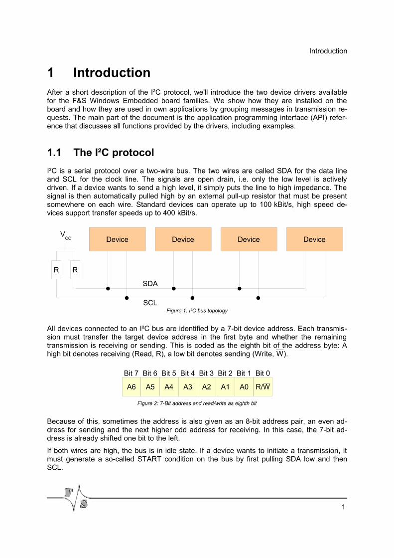
I²C is a serial protocol over a two-wire bus. The two wires are called SDA for the data lineand SCL for the clock line. The signals are open drain, i.e. only the low level is activelydriven. If a device wants to send a high level, it simply puts the line to high impedance. Thesignal is then automatically pulled high by an external pull-up resistor that must be presentsomewhere on each wire. Standard devices can operate up to 100 kBit/s, high speed de-vices support transfer speeds up to 400 kBit/s.
All devices connected to an I²C bus are identified by a 7-bit device address. Each transmis-sion must transfer the target device address in the first byte and whether the remainingtransmission is receiving or sending. This is coded as the eighth bit of the address byte: Ahigh bit denotes receiving (Read, R), a low bit denotes sending (Write, W).
Because of this, sometimes the address is also given as an 8-bit address pair, an even ad-dress for sending and the next higher odd address for receiving. In this case, the 7-bit ad-dress is already shifted one bit to the left.
If both wires are high, the bus is in idle state. If a device wants to initiate a transmission, itmust generate a so-called START condition on the bus by first pulling SDA low and thenSCL.
1
Figure 2: 7-Bit address and read/write as eighth bit
A6
Bit 7
A5
Bit 6
A4
Bit 5
A3
Bit 4
A2
Bit 3
A1
Bit 2
A0
Bit 1
R/W
Bit 0
Figure 1: I²C bus topology
Device Device Device Device
R R
VCC
SDA
SCL
Introduction
From now on this device is the master during this transmission. That means it must providethe target address of the device it wants to talk to and determine the transmission direction.Only the addressed device (the slave) is allowed to answer, all other devices must stay silentduring this transmission. The master is also responsible for toggling the SCL clock line dur-ing the whole transmission.
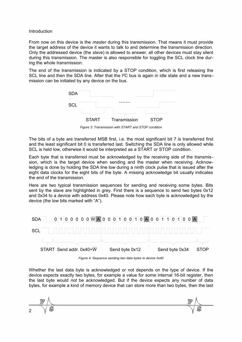
The end of the transmission is indicated by a STOP condition, which is first releasing theSCL line and then the SDA line. After that the I²C bus is again in idle state and a new trans-mission can be initiated by any device on the bus.
The bits of a byte are transferred MSB first, i.e. the most significant bit 7 is transferred firstand the least significant bit 0 is transferred last. Switching the SDA line is only allowed whileSCL is held low, otherwise it would be interpreted as a START or STOP condition.
Each byte that is transferred must be acknowledged by the receiving side of the transmis-sion, which is the target device when sending and the master when receiving. Acknow-ledging is done by holding the SDA line low during a ninth clock pulse that is issued after theeight data clocks for the eight bits of the byte. A missing acknowledge bit usually indicatesthe end of the transmission.
Here are two typical transmission sequences for sending and receiving some bytes. Bitssent by the slave are highlighted in grey. First there is a sequence to send two bytes 0x12and 0x34 to a device with address 0x40. Please note how each byte is acknowledged by thedevice (the low bits marked with “A”).
Whether the last data byte is acknowledged or not depends on the type of device. If thedevice expects exactly two bytes, for example a value for some internal 16-bit register, thenthe last byte would not be acknowledged. But if the device expects any number of databytes, for example a kind of memory device that can store more than two bytes, then the last
2
Figure 4: Sequence sending two data bytes to device 0x40
AAASDA
SCL
START STOPSend addr. 0x40+W Send byte 0x12 Send byte 0x34
0 1 0 0 0 0 0 W 0 0 0 1 0 0 1 0 0 0 1 1 0 1 0 0
Figure 3: Transmission with START and STOP condition
.......SDA
SCL
START STOPTransmission
Introduction
byte is acknowledged (like in the figure) and the master simply stops the sequence at anytime by issuing the STOP condition.
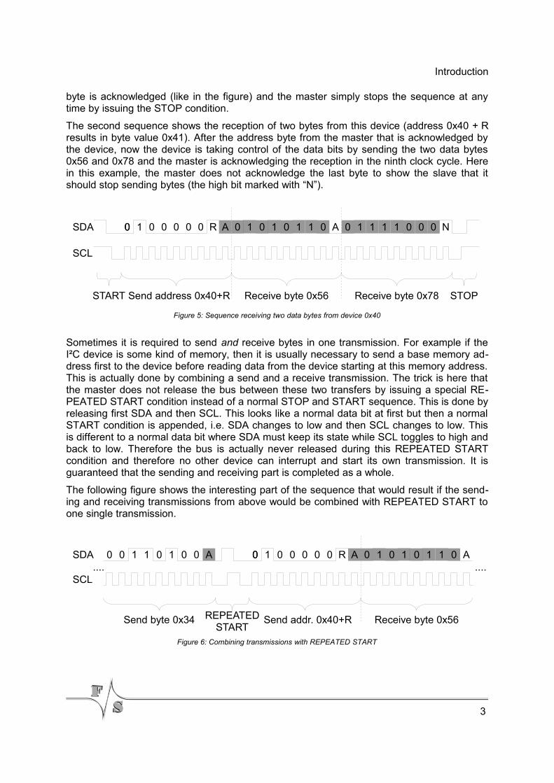
The second sequence shows the reception of two bytes from this device (address 0x40 + Rresults in byte value 0x41). After the address byte from the master that is acknowledged bythe device, now the device is taking control of the data bits by sending the two data bytes0x56 and 0x78 and the master is acknowledging the reception in the ninth clock cycle. Herein this example, the master does not acknowledge the last byte to show the slave that itshould stop sending bytes (the high bit marked with “N”).
Sometimes it is required to send and receive bytes in one transmission. For example if theI²C device is some kind of memory, then it is usually necessary to send a base memory ad-dress first to the device before reading data from the device starting at this memory address.This is actually done by combining a send and a receive transmission. The trick is here thatthe master does not release the bus between these two transfers by issuing a special RE-PEATED START condition instead of a normal STOP and START sequence. This is done byreleasing first SDA and then SCL. This looks like a normal data bit at first but then a normalSTART condition is appended, i.e. SDA changes to low and then SCL changes to low. Thisis different to a normal data bit where SDA must keep its state while SCL toggles to high andback to low. Therefore the bus is actually never released during this REPEATED STARTcondition and therefore no other device can interrupt and start its own transmission. It isguaranteed that the sending and receiving part is completed as a whole.
The following figure shows the interesting part of the sequence that would result if the send-ing and receiving transmissions from above would be combined with REPEATED START toone single transmission.
3
Figure 6: Combining transmissions with REPEATED START
SDA
SCL
A
REPEATED START
Send byte 0x34
0 0 1 1 0 1 0 0 0 1 0 1 0 1 1 0 AA
Send addr. 0x40+R Receive byte 0x56
0 1 0 0 0 0 0 R0........
Figure 5: Sequence receiving two data bytes from device 0x40
0 1 0 1 0 1 1 0 0 1 1 1 1 0 0 0 NAASDA
SCL
START STOP Send address 0x40+R Receive byte 0x56 Receive byte 0x78
0 1 0 0 0 0 0 R0
Introduction
1.2 The Device Drivers I2C and NI2C
F&S Elektronik Systeme provides several families of Single Board Computers that differ insize and performance: the armStone, efus, NetDCU, PicoMOD, PicoCOM and QBliss seriesof boards. F&S tries to keep the usage of the device drivers consistent across all theseboards. For I²C, there exist two different device drivers under Windows Embedded:
1. the I²C over GPIO device driver, called I2C, and
2. the Native I²C device driver using the I2C controller of the SoC, called NI2C.
The two drivers serve different purposes. I2C allows to establish many different I²C buses onone board at the expense of rather high CPU usage, while NI2C uses the existing dedicatedI²C hardware to get the best speed with as little CPU resources as possible.
Let's look at these two drivers one after the other.
1.2.1 Using GPIOs for I²C
The I2C device driver was the first I²C driver available for our boards. The idea was rathersimple: use two general purpose input/outputs (GPIOs) of the board to emulate an I²C bus.A low signal is done by switching the GPIO pin to output with logical 0. This actively drivesthe low signal on the line. A high signal is done by switching the GPIO pin to input, whichmeans high impedance. Then the pull-up resistor on the wire can pull the signal to logical 1.
This special handling of GPIOs is not implemented in hardware on the boards and must bedone in software. Especially the bit timing is rather critical and can only be implemented withbusy-wait loops. Neither sleeping functions nor interrupts can be used for these short delaysto free the CPU. As a result, this driver is rather CPU intensive. While transmitting, it will usemost of the CPU time. And even then, the final transfer speed is still limited. For example ona NetDCU8, the maximum speed possible with this driver is around 40 to 50 kBit/s. On otherboards it might be slightly higher, for example 100 kBit/s, but it is illusory to talk about themaximum I²C transfer speed of 400 kBit/s in connection with this driver.
On the other hand it is possible to build more than one I²C bus using this I2C driver. Each in-stance can use a different pair of GPIOs and thus the number of I²C buses is only limited bythe number of available GPIO pins. But be careful: if the buses want to transmit at the sametime, there will be additional delays by the competing drivers. It is just software that can onlybe executed quasi-parallel, i.e. one after the other in time slices.
1.2.2 Using Dedicated Hardware for I²C
As already mentioned, the I2C driver does not allow very high transfer speeds over the I²Cbus because of the pure software implementation. To obtain higher speeds, support from theunderlying hardware is required. This was the idea behind the introduction of the second I²Cdevice driver, the Native I2C, or NI2C for short. This driver provides access to the dedicated
4
Introduction
I²C hardware that is available on almost all of the currently available micro controllers. Noweven the maximum I²C speed of 400 kBit/s is no problem and the CPU is nearly completelyrelieved from the bit banging procedure. In fact the CPU has a rather low load when usingthis driver and can be used to perform other stuff in parallel to the I²C transmission.
Therefore this driver is the one that is best to use if only one I²C bus is necessary. Becausethe only downside of this driver is the fact, that all the micro controllers that we have used sofar only support at most one single I²C bus. And you have to use exactly one pair of I/O pinsof the board, as the hardware I²C bus is only available on exactly these pins.
The good news is, that both drivers, NI2C and I2C can be used in parallel if required. Thusyou can build one fast I²C bus with NI2C and several slow I²C buses with I2C all on oneboard.
1.2.3 Different Driver Versions
The first versions V1.x of the I2C driver used a rather simple application programming inter-face (API) that had the disadvantage, as we later discovered, that it could not be ported eas-ily to the .NET framework. Therefore when we introduced the NI2C driver, the API was com-pletely reworked. It proved to be a very powerful interface that worked very well also on allour new boards. This was the V1.x series of the NI2C drivers. The API was slightly improvedwhen we ported the NI2C driver to the PicoMOD3, which was the only driver with the V2.x in-terface.
In early summer of 2009, also new ports of the I2C driver were requested for our newboards. This was the point when we decided to bring the interface of the I2C driver in linewith the NI2C driver. Again the API was slightly improved, the I2C driver completely rewrittenand now both drivers, NI2C and I2C use the exact same API, which we now call the V3.x in-terface. Therefore all new ports of NI2C and I2C will sail under the V3.x version.
This document describes all features of this NI2C interface. Functions, that were not avail-able in V1.x and V2.x of the NI2C driver are marked appropriately. However please note thatthe now obsolete V1.x interface of the I2C driver is not covered in this document.
Which version you have can be determined by looking at the debug output of the board. Thefirst line starting with NI2C: or I2C: shows the appropriate driver version. Somewhere dur-ing V1.x there was also an IOCTL command code added called IOCTL_DRIVER_GETINFO.If this command succeeds, it returns the appropriate driver version in a data structure, and ifit fails, it’s definitely an early V1.x driver.
Remark
In this document, we’ll use the generic term “NetDCU” for all our boards. It should also meanPicoMOD, PicoCOM or any other future board type or family, where the I²C drivers areavailable. We will also refer to the driver file generally as ni2c.dll or i2c.dll respect-ively, even if the real name may have a board specific prefix added, e.g. pm3_ni2c.dll onthe PicoMOD3. We hope that this does not cause any inconvenience.
5
Pin Assignment
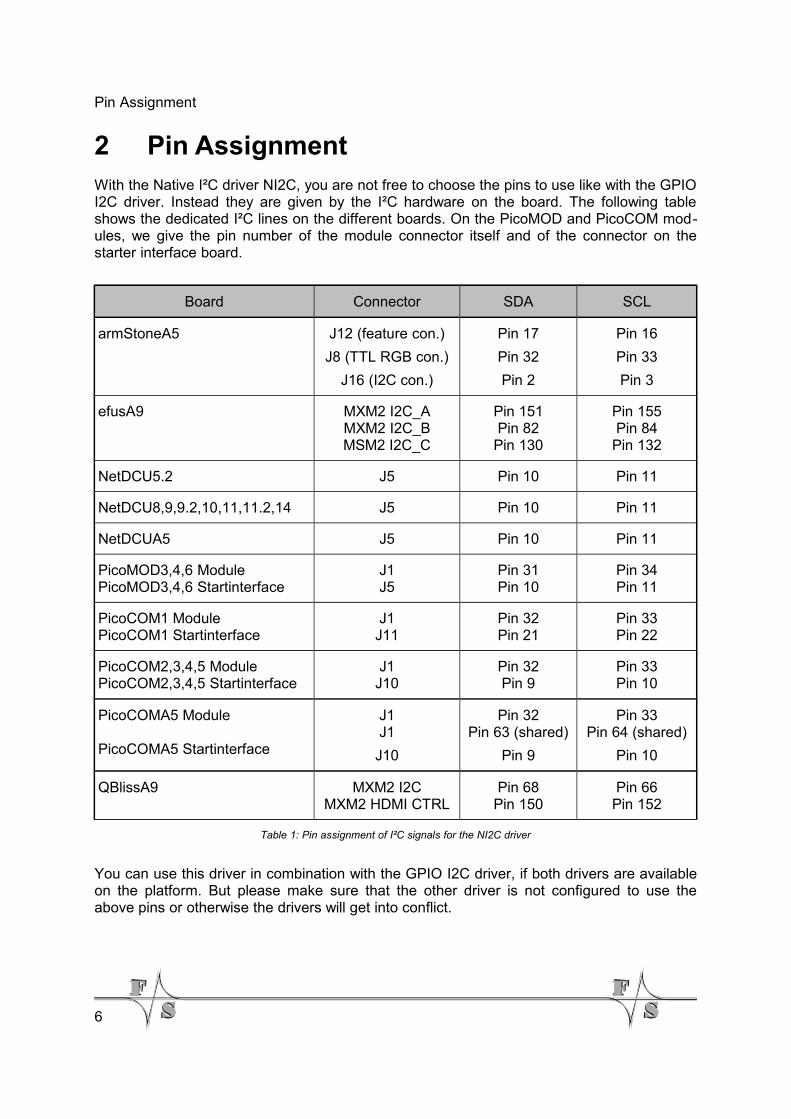
2 Pin AssignmentWith the Native I²C driver NI2C, you are not free to choose the pins to use like with the GPIOI2C driver. Instead they are given by the I²C hardware on the board. The following tableshows the dedicated I²C lines on the different boards. On the PicoMOD and PicoCOM mod-ules, we give the pin number of the module connector itself and of the connector on thestarter interface board.
Board Connector SDA SCL
armStoneA5 J12 (feature con.)
J8 (TTL RGB con.)
J16 (I2C con.)
Pin 17
Pin 32
Pin 2
Pin 16
Pin 33
Pin 3
efusA9 MXM2 I2C_AMXM2 I2C_BMSM2 I2C_C
Pin 151Pin 82
Pin 130
Pin 155Pin 84
Pin 132
NetDCU5.2 J5 Pin 10 Pin 11
NetDCU8,9,9.2,10,11,11.2,14 J5 Pin 10 Pin 11
NetDCUA5 J5 Pin 10 Pin 11
PicoMOD3,4,6 ModulePicoMOD3,4,6 Startinterface
J1J5
Pin 31Pin 10
Pin 34Pin 11
PicoCOM1 ModulePicoCOM1 Startinterface
J1J11
Pin 32Pin 21
Pin 33Pin 22
PicoCOM2,3,4,5 ModulePicoCOM2,3,4,5 Startinterface
J1J10
Pin 32Pin 9
Pin 33Pin 10
PicoCOMA5 Module
PicoCOMA5 Startinterface
J1J1
J10
Pin 32Pin 63 (shared)
Pin 9
Pin 33Pin 64 (shared)
Pin 10
QBlissA9 MXM2 I2CMXM2 HDMI CTRL
Pin 68Pin 150
Pin 66Pin 152
Table 1: Pin assignment of I²C signals for the NI2C driver
You can use this driver in combination with the GPIO I2C driver, if both drivers are availableon the platform. But please make sure that the other driver is not configured to use theabove pins or otherwise the drivers will get into conflict.
6
Installing the I2C and/or NI2C Driver
3 Installing the I2C and/or NI2C DriverOn many F&S boards, the NI2C driver is already pre-installed in the WindowsCE kernelimage as I2C1:. As a consequence, we recommend to install the I2C driver starting withnumber 2, i.e. I2C2:, I2C3:, and so on. We usually provide special Windows Cabinet Files(“CAB-Files”) for an automatic installation, but you can also do the installation manually.
Remark
If you also plan to use the 5-wire touch panel adapter NetDCU-ADP-TP5 from F&S, thenni2c.dll must be installed as I2C1:, or the touch panel won’t work. Please refer to theseparate document “NetDCU: NetDCU-ADP-TP5 – 5-Wire Touch Panel” (NetDCU_ADP-TP5_eng.pdf) for how to set up the touch panel.
3.1 Installation with the CAB file
The easiest way to install one of the drivers is to use the provided Windows Cabinet Fileni2c.cab or i2c.cab respectively. Just copy this file to the board (e.g. to the root direct-ory) and double click on it. This will automatically install the driver as I2C1: (NI2C) orI2C2: (I2C). When asked for a destination directory, just click OK. This will install the driverin directory \FFSDISK. All registry settings will be done for the default values and the CABfile will vanish again when done.
If you don’t have access to a mouse or touch panel on the NetDCU, or if you even don’t usea display at all, you can also do the CAB file installation on the command line. Just type thefollowing command:
wceload /noui ni2c.cab
or
wceload /noui i2c.cab
respectively.
If you need settings other than the defaults, you can edit the registry values anytime after in-stallation is complete.
3.2 Manual installation and configuration
You can also do the installation by hand. This requires setting some registry values. Installa-tion of the NI2C and I2C drivers takes place in the registry under
[HKLM\Drivers\BuiltIn\I2Cn]
where n is the number of the device (usually 1 for NI2C and 2, 3, 4, and so on for I2C).
7
Installing the I2C and/or NI2C Driver
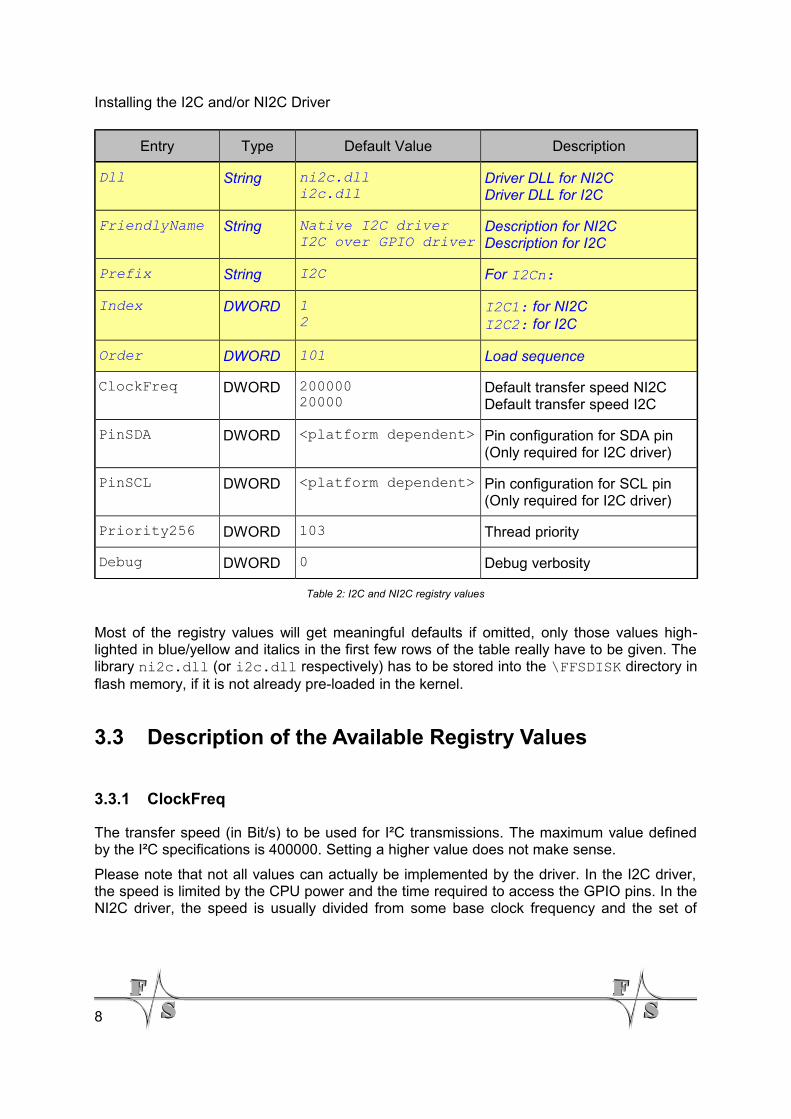
Entry Type Default Value Description
Dll String ni2c.dlli2c.dll
Driver DLL for NI2CDriver DLL for I2C
FriendlyName String Native I2C driverI2C over GPIO driver
Description for NI2CDescription for I2C
Prefix String I2C For I2Cn:
Index DWORD 12
I2C1: for NI2CI2C2: for I2C
Order DWORD 101 Load sequence
ClockFreq DWORD 20000020000
Default transfer speed NI2CDefault transfer speed I2C
PinSDA DWORD <platform dependent> Pin configuration for SDA pin (Only required for I2C driver)
PinSCL DWORD <platform dependent> Pin configuration for SCL pin (Only required for I2C driver)
Priority256 DWORD 103 Thread priority
Debug DWORD 0 Debug verbosity
Table 2: I2C and NI2C registry values
Most of the registry values will get meaningful defaults if omitted, only those values high-lighted in blue/yellow and italics in the first few rows of the table really have to be given. Thelibrary ni2c.dll (or i2c.dll respectively) has to be stored into the \FFSDISK directory inflash memory, if it is not already pre-loaded in the kernel.
3.3 Description of the Available Registry Values
3.3.1 ClockFreq
The transfer speed (in Bit/s) to be used for I²C transmissions. The maximum value definedby the I²C specifications is 400000. Setting a higher value does not make sense.
Please note that not all values can actually be implemented by the driver. In the I2C driver,the speed is limited by the CPU power and the time required to access the GPIO pins. In theNI2C driver, the speed is usually divided from some base clock frequency and the set of
8
Installing the I2C and/or NI2C Driver
possible dividers decides which speeds are actually available. Nevertheless the driver al-ways tries to use a setting as close as possible to the value given in ClockFreq.
3.3.2 PinSDA, PinSCL
These two settings are only required for the I2C driver. They define the pin numbers to beused for the SDA and SCL signals. As the pin-numbering is not common on all platformsthese values are board specific. See documentation “DeviceDriver_xxx.pdf” chapter “DigitalI/O” for more information.
On NetDCU-familyThe value is the same that you would set for this pin in the UseAsIO entry of the DIO driverfor the board (please refer to the separate “NetDCU Device Drivers” document).
On PicoMOD- / PicoCOM-familyThis value is the IO-Pin number of the pin the signal should be available on. Please refer tothe separate “PicoMOD/PicoCOM Device Drivers” document for further information on IO-Pin numbering.
Attention!
The NI2C driver has dedicated pins that can not be changed and thus don't need anyconfiguration (see chapter 2 on page 6).
3.3.3 Priority256
The actual transfer will take place with the Windows CE priority given in Priority256.Changing this value is only required if the I2C or NI2C driver does interfere with otherdrivers. A lower value means higher priority, a higher value means lower priority. The regionis 0 to 255.
Attention!
A value too small (= very high priority) may block other device drivers. This may result insporadic malfunctions if these drivers are interrupted for too long.
Note 1: Wrong priority settings may result in malfunctions
3.3.4 Debug
If the Debug entry is set to a value different to zero, the driver will output additional informa-tion on the debug port. Each bit enables a different category of output. This information is
9

Installing the I2C and/or NI2C Driver
usually not required and only necessary when looking for errors in the driver. Keep this valueat zero to have the best possible performance.
10
The I²C Drivers in Applications
4 The I²C Drivers in ApplicationsBoth I²C drivers are designed to work as the sole master on the bus. Therefore no otherdevice is allowed to take the role of a master and start an I²C transmission. They all have toact as slaves.
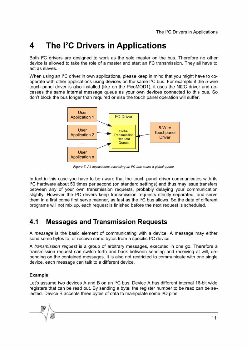
When using an I²C driver in own applications, please keep in mind that you might have to co-operate with other applications using devices on the same I²C bus. For example if the 5-wiretouch panel driver is also installed (like on the PicoMOD1), it uses the NI2C driver and ac-cesses the same internal message queue as your own devices connected to this bus. Sodon’t block the bus longer than required or else the touch panel operation will suffer.
In fact in this case you have to be aware that the touch panel driver communicates with itsI²C hardware about 50 times per second (on standard settings) and thus may issue transfersbetween any of your own transmission requests, probably delaying your communicationslightly. However the I²C drivers keep transmission requests strictly separated, and servethem in a first come first serve manner, as fast as the I²C bus allows. So the data of differentprograms will not mix up, each request is finished before the next request is scheduled.
4.1 Messages and Transmission Requests
A message is the basic element of communicating with a device. A message may eithersend some bytes to, or receive some bytes from a specific I²C device.
A transmission request is a group of arbitrary messages, executed in one go. Therefore atransmission request can switch forth and back between sending and receiving at will, de-pending on the contained messages. It is also not restricted to communicate with one singledevice, each message can talk to a different device.
Example
Let's assume two devices A and B on an I²C bus. Device A has different internal 16-bit wideregisters that can be read out. By sending a byte, the register number to be read can be se-lected. Device B accepts three bytes of data to manipulate some I/O pins.
11
Figure 7: All applications accessing an I²C bus share a global queue
I²C DriverUser
Application 1
User Application n
5-Wire Touchpanel
Driver
Global Transmission
Request Queue...
User Application 2
The I²C Drivers in Applications
Then the following four messages could be combined to one transmission request.
1. Send 1 byte to device A to select a register number
2. Receive 2 bytes from device A to read this register
3. Send 3 bytes to device B to set the I/Os
4. Receive another 2 bytes from device A to read the same register again
Such a transmission request is handled as a whole, even if other requests are in the queue.It is essential that every program participating in the I²C bus communication behaves fair andonly groups those messages in a single transmission request that really must belong to-gether and can not be split.
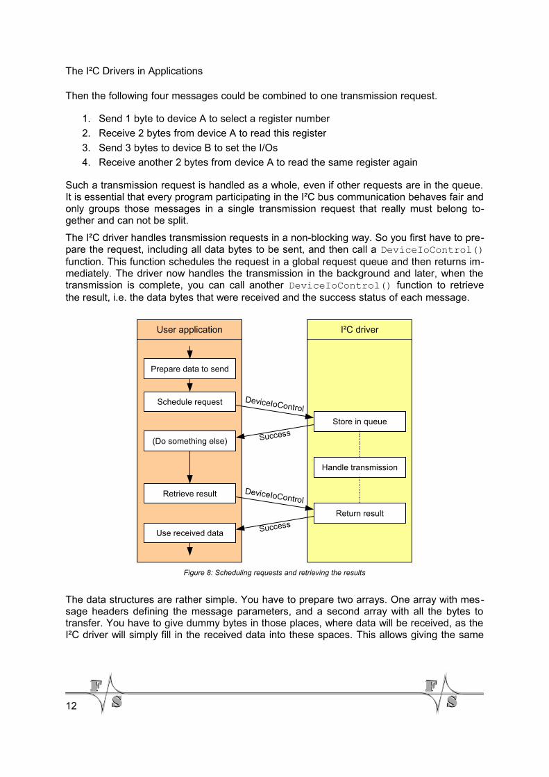
The I²C driver handles transmission requests in a non-blocking way. So you first have to pre-pare the request, including all data bytes to be sent, and then call a DeviceIoControl()function. This function schedules the request in a global request queue and then returns im-mediately. The driver now handles the transmission in the background and later, when thetransmission is complete, you can call another DeviceIoControl() function to retrievethe result, i.e. the data bytes that were received and the success status of each message.
The data structures are rather simple. You have to prepare two arrays. One array with mes-sage headers defining the message parameters, and a second array with all the bytes totransfer. You have to give dummy bytes in those places, where data will be received, as theI²C driver will simply fill in the received data into these spaces. This allows giving the same
12
Figure 8: Scheduling requests and retrieving the results
Prepare data to send
Schedule request
Store in queue
Handle transmission
Return result
(Do something else)
Retrieve result
Use received data
DeviceIoControl
Success
User application I²C driver
DeviceIoControl
Success
The I²C Drivers in Applications
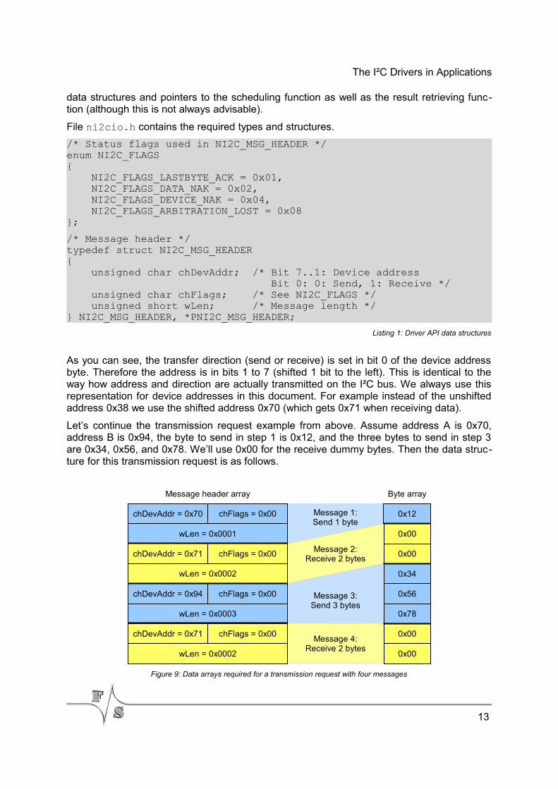
data structures and pointers to the scheduling function as well as the result retrieving func-tion (although this is not always advisable).
File ni2cio.h contains the required types and structures.
/* Status flags used in NI2C_MSG_HEADER */enum NI2C_FLAGS{ NI2C_FLAGS_LASTBYTE_ACK = 0x01, NI2C_FLAGS_DATA_NAK = 0x02, NI2C_FLAGS_DEVICE_NAK = 0x04, NI2C_FLAGS_ARBITRATION_LOST = 0x08};
/* Message header */typedef struct NI2C_MSG_HEADER{ unsigned char chDevAddr; /* Bit 7..1: Device address Bit 0: 0: Send, 1: Receive */ unsigned char chFlags; /* See NI2C_FLAGS */ unsigned short wLen; /* Message length */} NI2C_MSG_HEADER, *PNI2C_MSG_HEADER;
Listing 1: Driver API data structures
As you can see, the transfer direction (send or receive) is set in bit 0 of the device addressbyte. Therefore the address is in bits 1 to 7 (shifted 1 bit to the left). This is identical to theway how address and direction are actually transmitted on the I²C bus. We always use thisrepresentation for device addresses in this document. For example instead of the unshiftedaddress 0x38 we use the shifted address 0x70 (which gets 0x71 when receiving data).
Let’s continue the transmission request example from above. Assume address A is 0x70,address B is 0x94, the byte to send in step 1 is 0x12, and the three bytes to send in step 3are 0x34, 0x56, and 0x78. We’ll use 0x00 for the receive dummy bytes. Then the data struc-ture for this transmission request is as follows.
13
Figure 9: Data arrays required for a transmission request with four messages
0x12
0x00
0x00
0x34
0x56
0x78
0x00
0x00
chDevAddr = 0x70 chFlags = 0x00
wLen = 0x0001
chDevAddr = 0x71 chFlags = 0x00
wLen = 0x0002
chDevAddr = 0x94 chFlags = 0x00
wLen = 0x0003
chDevAddr = 0x71 chFlags = 0x00
wLen = 0x0002
Message header array Byte array
Message 1:Send 1 byte
Message 2:Receive 2 bytes
Message 3:Send 3 bytes
Message 4:Receive 2 bytes
The I²C Drivers in Applications
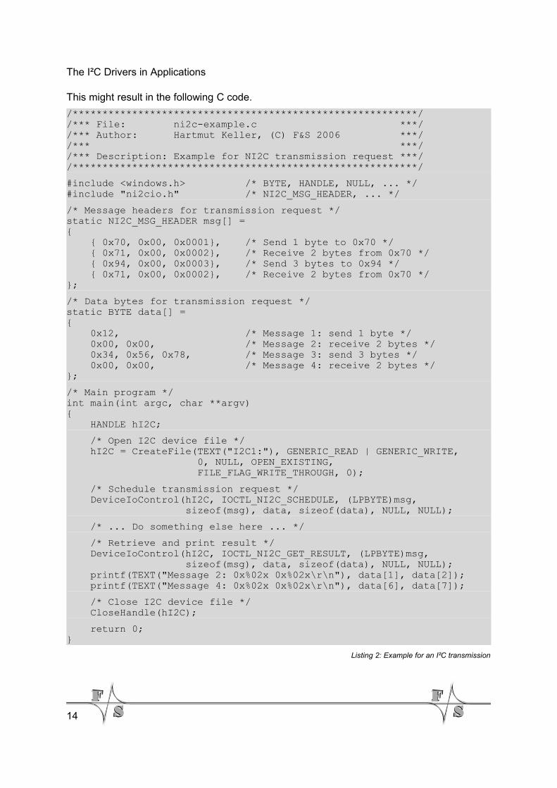
This might result in the following C code.
/**********************************************************//*** File: ni2c-example.c ***//*** Author: Hartmut Keller, (C) F&S 2006 ***//*** ***//*** Description: Example for NI2C transmission request ***//**********************************************************/
#include <windows.h> /* BYTE, HANDLE, NULL, ... */#include "ni2cio.h" /* NI2C_MSG_HEADER, ... */
/* Message headers for transmission request */static NI2C_MSG_HEADER msg[] ={ { 0x70, 0x00, 0x0001}, /* Send 1 byte to 0x70 */ { 0x71, 0x00, 0x0002}, /* Receive 2 bytes from 0x70 */ { 0x94, 0x00, 0x0003}, /* Send 3 bytes to 0x94 */ { 0x71, 0x00, 0x0002}, /* Receive 2 bytes from 0x70 */};
/* Data bytes for transmission request */static BYTE data[] ={ 0x12, /* Message 1: send 1 byte */ 0x00, 0x00, /* Message 2: receive 2 bytes */ 0x34, 0x56, 0x78, /* Message 3: send 3 bytes */ 0x00, 0x00, /* Message 4: receive 2 bytes */};
/* Main program */int main(int argc, char **argv){ HANDLE hI2C;
/* Open I2C device file */ hI2C = CreateFile(TEXT("I2C1:"), GENERIC_READ | GENERIC_WRITE, 0, NULL, OPEN_EXISTING, FILE_FLAG_WRITE_THROUGH, 0);
/* Schedule transmission request */ DeviceIoControl(hI2C, IOCTL_NI2C_SCHEDULE, (LPBYTE)msg, sizeof(msg), data, sizeof(data), NULL, NULL);
/* ... Do something else here ... */
/* Retrieve and print result */ DeviceIoControl(hI2C, IOCTL_NI2C_GET_RESULT, (LPBYTE)msg, sizeof(msg), data, sizeof(data), NULL, NULL); printf(TEXT("Message 2: 0x%02x 0x%02x\r\n"), data[1], data[2]); printf(TEXT("Message 4: 0x%02x 0x%02x\r\n"), data[6], data[7]);
/* Close I2C device file */ CloseHandle(hI2C);
return 0;}
Listing 2: Example for an I²C transmission
14
The I²C Drivers in Applications
4.2 Acknowledgement Mode and Status Flags
The chFlags value in the message header serves two different purposes: setting the ac-knowledgement mode for receiving messages and returning the status of all transmissions.
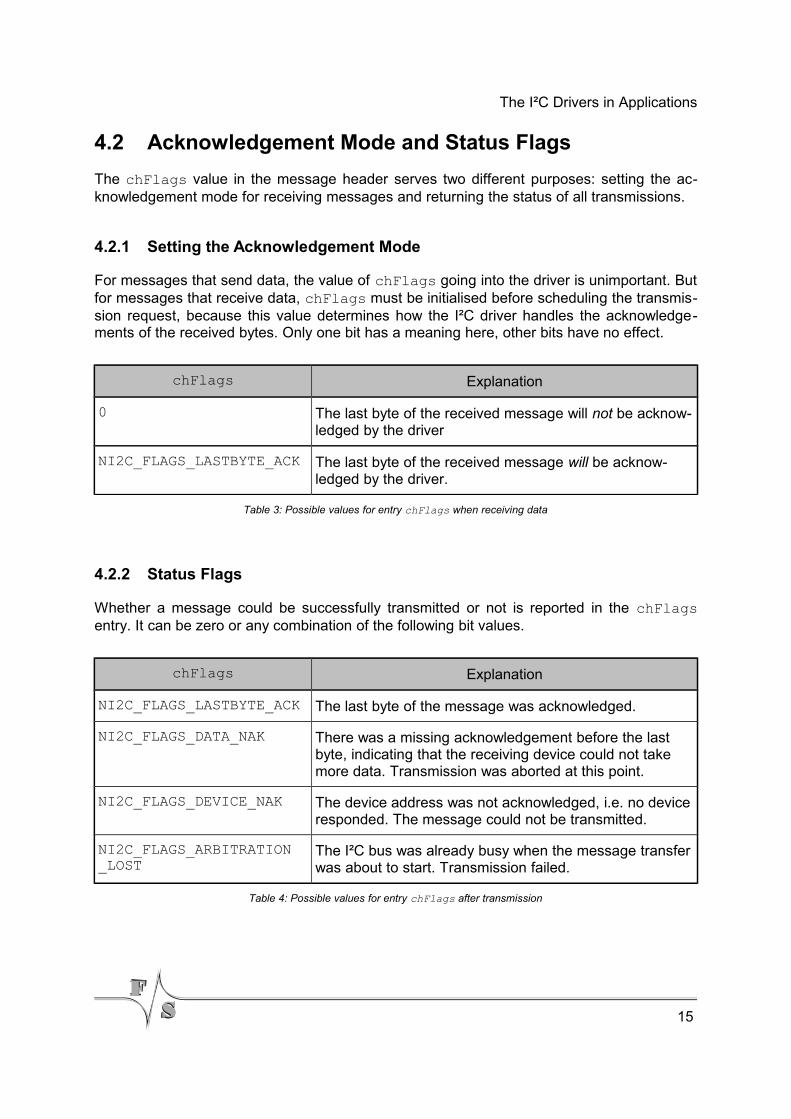
4.2.1 Setting the Acknowledgement Mode
For messages that send data, the value of chFlags going into the driver is unimportant. Butfor messages that receive data, chFlags must be initialised before scheduling the transmis-sion request, because this value determines how the I²C driver handles the acknowledge-ments of the received bytes. Only one bit has a meaning here, other bits have no effect.
chFlags Explanation
0 The last byte of the received message will not be acknow-ledged by the driver
NI2C_FLAGS_LASTBYTE_ACK The last byte of the received message will be acknow-ledged by the driver.
Table 3: Possible values for entry chFlags when receiving data
4.2.2 Status Flags
Whether a message could be successfully transmitted or not is reported in the chFlagsentry. It can be zero or any combination of the following bit values.
chFlags Explanation
NI2C_FLAGS_LASTBYTE_ACK The last byte of the message was acknowledged.
NI2C_FLAGS_DATA_NAK There was a missing acknowledgement before the last byte, indicating that the receiving device could not take more data. Transmission was aborted at this point.
NI2C_FLAGS_DEVICE_NAK The device address was not acknowledged, i.e. no deviceresponded. The message could not be transmitted.
NI2C_FLAGS_ARBITRATION_LOST
The I²C bus was already busy when the message transferwas about to start. Transmission failed.
Table 4: Possible values for entry chFlags after transmission
15
The I²C Drivers in Applications
After having retrieved the result of a transmission request, you should check the chFlagsvalues of all individual messages to get a status report.
Here, NI2C_FLAGS_LASTBYTE_ACK is just a result value, telling whether the receivingdevice did acknowledge the last byte or not. This might be an indication for some error asthe receiving device expected more data, but for some devices that can accept any numberof bytes, this behaviour is completely OK. For this reason it must be decided by the applica-tion whether this is an error or not.
All other flags indicate an aborted transfer. That means at some point in the message thetransmission stopped because of an error and the remaining bytes of the message could notbe transferred. To mark the abortion point within the message, the I²C driver inverts the bitpatterns of all bytes of the remaining message that were not transmitted. In case of a receiv-ing message, the dummy bytes that were in the data array before the request was sched-uled, are inverted. Therefore by comparing the data array that was scheduled to the data ar-ray returned in the result you can tell for each message exactly where the error occurred.
By the way this is the main reason why it is sometimes no good idea to use the same arraysin the calls to scheduling a request and getting the result. As the data would be overwritten,It would not be possible to compare the “before” and “after” state.
Example
The following message bytes should be sent to some device:
0x11 0x22 0x33 0x44 0x55
After the transmission, the chFlags value shows that the NI2C_FLAGS_DATA_NAK flag isset. The data bytes array now shows the corresponding bytes as
0x11 0x22 0x33 0xBB 0xAA
This tells us that the first three bytes were successfully transmitted, but the acknowledge-ment was missing on the third byte, and therefore the last two bytes were not transmittedanymore.
4.3 Scanning the I²C Bus for Devices
If the hardware configuration on the I²C bus is variable and not some fix arrangement, it isusually one of the first tasks to determine which devices are actually present on the bus.This is called scanning the bus.
The idea is rather simple. Each transmission starts with the address of the target device. Ifthe device is present, it will acknowledge the address. If not, NI2C_FLAGS_DEVICE_NAK willbe set. It is not necessary to actually transfer some data with the message, just sending theaddress (usually together with W) is enough. Then a bus scan is nothing more than sendingall the addresses of the devices that are expected on the bus one after the other and lookingat the NI2C_FLAGS_DEVICE_NAK flag on return.
16
The I²C Drivers in Applications
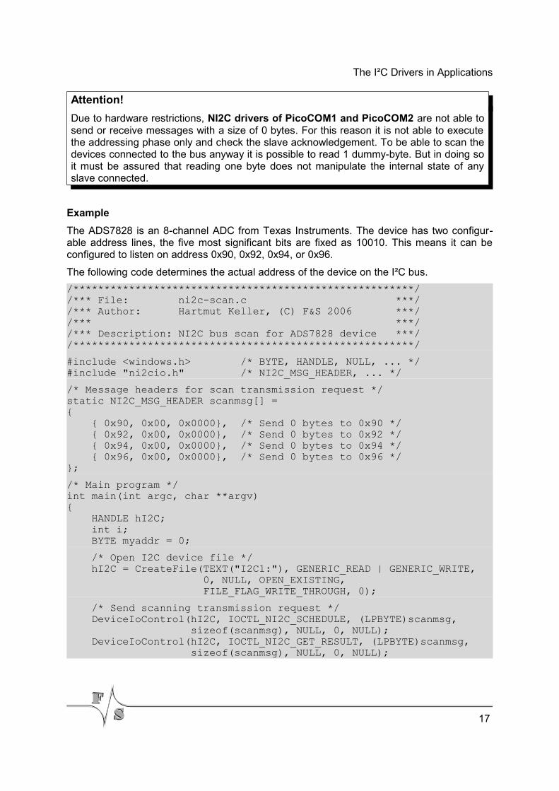
Attention!
Due to hardware restrictions, NI2C drivers of PicoCOM1 and PicoCOM2 are not able tosend or receive messages with a size of 0 bytes. For this reason it is not able to executethe addressing phase only and check the slave acknowledgement. To be able to scan thedevices connected to the bus anyway it is possible to read 1 dummy-byte. But in doing soit must be assured that reading one byte does not manipulate the internal state of anyslave connected.
Example
The ADS7828 is an 8-channel ADC from Texas Instruments. The device has two configur-able address lines, the five most significant bits are fixed as 10010. This means it can beconfigured to listen on address 0x90, 0x92, 0x94, or 0x96.
The following code determines the actual address of the device on the I²C bus.
/*******************************************************//*** File: ni2c-scan.c ***//*** Author: Hartmut Keller, (C) F&S 2006 ***//*** ***//*** Description: NI2C bus scan for ADS7828 device ***//*******************************************************/
#include <windows.h> /* BYTE, HANDLE, NULL, ... */#include "ni2cio.h" /* NI2C_MSG_HEADER, ... */
/* Message headers for scan transmission request */static NI2C_MSG_HEADER scanmsg[] ={ { 0x90, 0x00, 0x0000}, /* Send 0 bytes to 0x90 */ { 0x92, 0x00, 0x0000}, /* Send 0 bytes to 0x92 */ { 0x94, 0x00, 0x0000}, /* Send 0 bytes to 0x94 */ { 0x96, 0x00, 0x0000}, /* Send 0 bytes to 0x96 */};
/* Main program */int main(int argc, char **argv){ HANDLE hI2C; int i; BYTE myaddr = 0;
/* Open I2C device file */ hI2C = CreateFile(TEXT("I2C1:"), GENERIC_READ | GENERIC_WRITE, 0, NULL, OPEN_EXISTING, FILE_FLAG_WRITE_THROUGH, 0);
/* Send scanning transmission request */ DeviceIoControl(hI2C, IOCTL_NI2C_SCHEDULE, (LPBYTE)scanmsg, sizeof(scanmsg), NULL, 0, NULL); DeviceIoControl(hI2C, IOCTL_NI2C_GET_RESULT, (LPBYTE)scanmsg, sizeof(scanmsg), NULL, 0, NULL);
17
The I²C Drivers in Applications
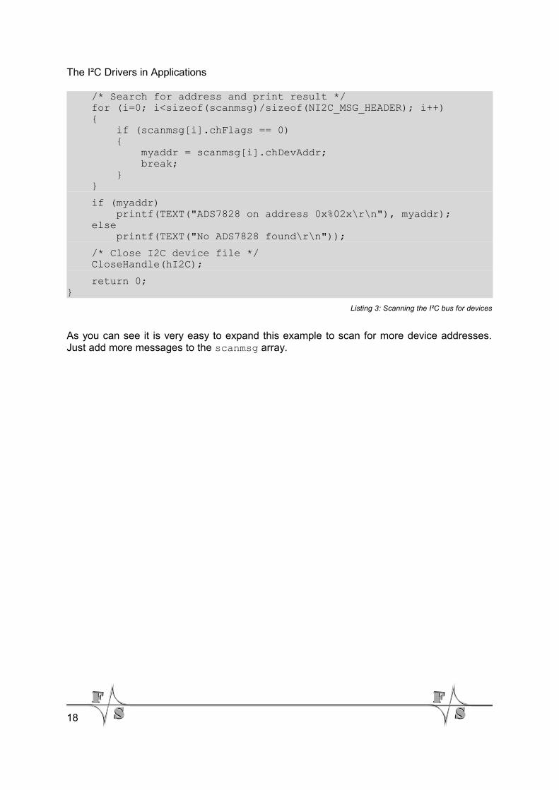
/* Search for address and print result */ for (i=0; i<sizeof(scanmsg)/sizeof(NI2C_MSG_HEADER); i++) { if (scanmsg[i].chFlags == 0) { myaddr = scanmsg[i].chDevAddr; break; } }
if (myaddr) printf(TEXT("ADS7828 on address 0x%02x\r\n"), myaddr); else printf(TEXT("No ADS7828 found\r\n"));
/* Close I2C device file */ CloseHandle(hI2C);
return 0;}
Listing 3: Scanning the I²C bus for devices
As you can see it is very easy to expand this example to scan for more device addresses.Just add more messages to the scanmsg array.
18
NI2C Reference
5 NI2C Reference
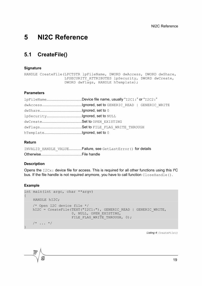
5.1 CreateFile()
Signature
HANDLE CreateFile(LPCTSTR lpFileName, DWORD dwAccess, DWORD dwShare, LPSECURITY_ATTRIBUTES lpSecurity, DWORD dwCreate, DWORD dwFlags, HANDLE hTemplate);
Parameters
lpFileName.................................Device file name, usually “I2C1:” or “I2C2:”
dwAccess.....................................Ignored, set to GENERIC_READ | GENERIC_WRITE
dwShare.......................................Ignored, set to 0
lpSecurity.................................Ignored, set to NULL
dwCreate.....................................Set to OPEN_EXISTING
dwFlags.......................................Set to FILE_FLAG_WRITE_THROUGH
hTemplate...................................Ignored, set to 0
Return
INVALID_HANDLE_VALUE............Failure, see GetLastError() for details
Otherwise......................................File handle
Description
Opens the I2Cx: device file for access. This is required for all other functions using this I²Cbus. If the file handle is not required anymore, you have to call function CloseHandle().
Example
int main(int argc, char **argv){ HANDLE hI2C;
/* Open I2C device file */ hI2C = CreateFile(TEXT("I2C1:"), GENERIC_READ | GENERIC_WRITE, 0, NULL, OPEN_EXISTING, FILE_FLAG_WRITE_THROUGH, 0);
/* ... */}
Listing 4: CreateFile()
19
NI2C Reference
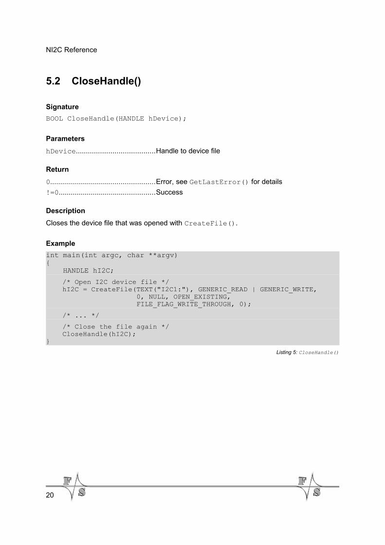
5.2 CloseHandle()
Signature
BOOL CloseHandle(HANDLE hDevice);
Parameters
hDevice.......................................Handle to device file
Return
0....................................................Error, see GetLastError() for details
!=0................................................Success
Description
Closes the device file that was opened with CreateFile().
Example
int main(int argc, char **argv){ HANDLE hI2C;
/* Open I2C device file */ hI2C = CreateFile(TEXT("I2C1:"), GENERIC_READ | GENERIC_WRITE, 0, NULL, OPEN_EXISTING, FILE_FLAG_WRITE_THROUGH, 0);
/* ... */
/* Close the file again */ CloseHandle(hI2C);}
Listing 5: CloseHandle()
20
NI2C Reference
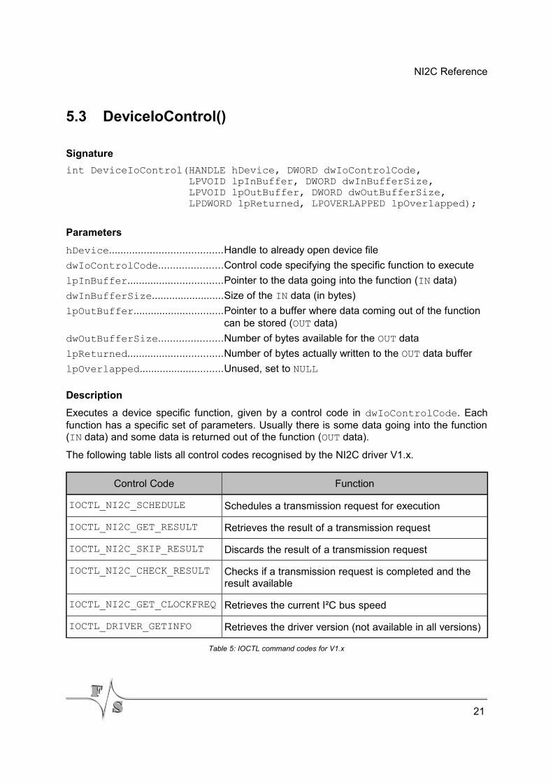
5.3 DeviceIoControl()
Signature
int DeviceIoControl(HANDLE hDevice, DWORD dwIoControlCode, LPVOID lpInBuffer, DWORD dwInBufferSize, LPVOID lpOutBuffer, DWORD dwOutBufferSize, LPDWORD lpReturned, LPOVERLAPPED lpOverlapped);
Parameters
hDevice.......................................Handle to already open device file
dwIoControlCode......................Control code specifying the specific function to execute
lpInBuffer.................................Pointer to the data going into the function (IN data)
dwInBufferSize.........................Size of the IN data (in bytes)
lpOutBuffer...............................Pointer to a buffer where data coming out of the function can be stored (OUT data)
dwOutBufferSize......................Number of bytes available for the OUT data
lpReturned.................................Number of bytes actually written to the OUT data buffer
lpOverlapped.............................Unused, set to NULL
Description
Executes a device specific function, given by a control code in dwIoControlCode. Eachfunction has a specific set of parameters. Usually there is some data going into the function(IN data) and some data is returned out of the function (OUT data).
The following table lists all control codes recognised by the NI2C driver V1.x.
Control Code Function
IOCTL_NI2C_SCHEDULE Schedules a transmission request for execution
IOCTL_NI2C_GET_RESULT Retrieves the result of a transmission request
IOCTL_NI2C_SKIP_RESULT Discards the result of a transmission request
IOCTL_NI2C_CHECK_RESULT Checks if a transmission request is completed and the result available
IOCTL_NI2C_GET_CLOCKFREQ Retrieves the current I²C bus speed
IOCTL_DRIVER_GETINFO Retrieves the driver version (not available in all versions)
Table 5: IOCTL command codes for V1.x
21
NI2C Reference
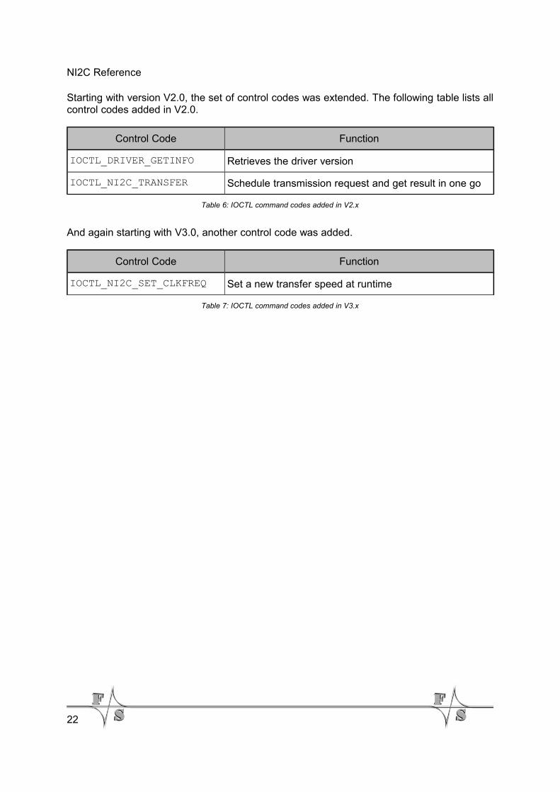
Starting with version V2.0, the set of control codes was extended. The following table lists allcontrol codes added in V2.0.
Control Code Function
IOCTL_DRIVER_GETINFO Retrieves the driver version
IOCTL_NI2C_TRANSFER Schedule transmission request and get result in one go
Table 6: IOCTL command codes added in V2.x
And again starting with V3.0, another control code was added.
Control Code Function
IOCTL_NI2C_SET_CLKFREQ Set a new transfer speed at runtime
Table 7: IOCTL command codes added in V3.x
22
NI2C Reference
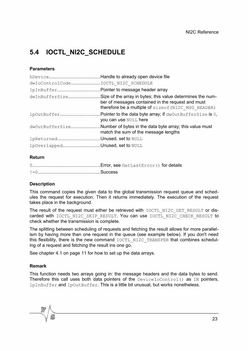
5.4 IOCTL_NI2C_SCHEDULE
Parameters
hDevice.......................................Handle to already open device filedwIoControlCode......................IOCTL_NI2C_SCHEDULE
lpInBuffer.................................Pointer to message header array
dwInBufferSize.........................Size of the array in bytes; this value determines the num-ber of messages contained in the request and must therefore be a multiple of sizeof(NI2C_MSG_HEADER)
lpOutBuffer...............................Pointer to the data byte array; if dwOutBufferSize is 0, you can use NULL here
dwOutBufferSize......................Number of bytes in the data byte array; this value must match the sum of the message lengths
lpReturned.................................Unused, set to NULL
lpOverlapped.............................Unused, set to NULL
Return
0....................................................Error, see GetLastError() for details
!=0................................................Success
Description
This command copies the given data to the global transmission request queue and sched-ules the request for execution. Then it returns immediately. The execution of the requesttakes place in the background.
The result of the request must either be retrieved with IOCTL_NI2C_GET_RESULT or dis-carded with IOCTL_NI2C_SKIP_RESULT. You can use IOCTL_NI2C_CHECK_RESULT tocheck whether the transmission is complete.
The splitting between scheduling of requests and fetching the result allows for more parallel-ism by having more than one request in the queue (see example below). If you don't needthis flexibility, there is the new command IOCTL_NI2C_TRANSFER that combines schedul-ing of a request and fetching the result ins one go.
See chapter 4.1 on page 11 for how to set up the data arrays.
Remark
This function needs two arrays going in: the message headers and the data bytes to send.Therefore this call uses both data pointers of the DeviceIoControl() as IN pointers,lpInBuffer and lpOutBuffer. This is a little bit unusual, but works nonetheless.
23
NI2C Reference
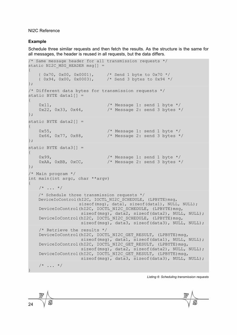
Example
Schedule three similar requests and then fetch the results. As the structure is the same forall messages, the header is reused in all requests, but the data differs.
/* Same message header for all transmission requests */static NI2C_MSG_HEADER msg[] ={ { 0x70, 0x00, 0x0001}, /* Send 1 byte to 0x70 */ { 0x94, 0x00, 0x0003}, /* Send 3 bytes to 0x94 */};
/* Different data bytes for transmission requests */static BYTE data1[] ={ 0x11, /* Message 1: send 1 byte */ 0x22, 0x33, 0x44, /* Message 2: send 3 bytes */};
static BYTE data2[] ={ 0x55, /* Message 1: send 1 byte */ 0x66, 0x77, 0x88, /* Message 2: send 3 bytes */};
static BYTE data3[] ={ 0x99, /* Message 1: send 1 byte */ 0xAA, 0xBB, 0xCC, /* Message 2: send 3 bytes */};
/* Main program */int main(int argc, char **argv){ /* ... */
/* Schedule three transmission requests */ DeviceIoControl(hI2C, IOCTL_NI2C_SCHEDULE, (LPBYTE)msg, sizeof(msg), data1, sizeof(data1), NULL, NULL); DeviceIoControl(hI2C, IOCTL_NI2C_SCHEDULE, (LPBYTE)msg, sizeof(msg), data2, sizeof(data2), NULL, NULL); DeviceIoControl(hI2C, IOCTL_NI2C_SCHEDULE, (LPBYTE)msg, sizeof(msg), data3, sizeof(data3), NULL, NULL);
/* Retrieve the results */ DeviceIoControl(hI2C, IOCTL_NI2C_GET_RESULT, (LPBYTE)msg, sizeof(msg), data1, sizeof(data1), NULL, NULL); DeviceIoControl(hI2C, IOCTL_NI2C_GET_RESULT, (LPBYTE)msg, sizeof(msg), data2, sizeof(data2), NULL, NULL); DeviceIoControl(hI2C, IOCTL_NI2C_GET_RESULT, (LPBYTE)msg, sizeof(msg), data3, sizeof(data3), NULL, NULL);
/* ... */}
Listing 6: Scheduling transmission requests
24
NI2C Reference
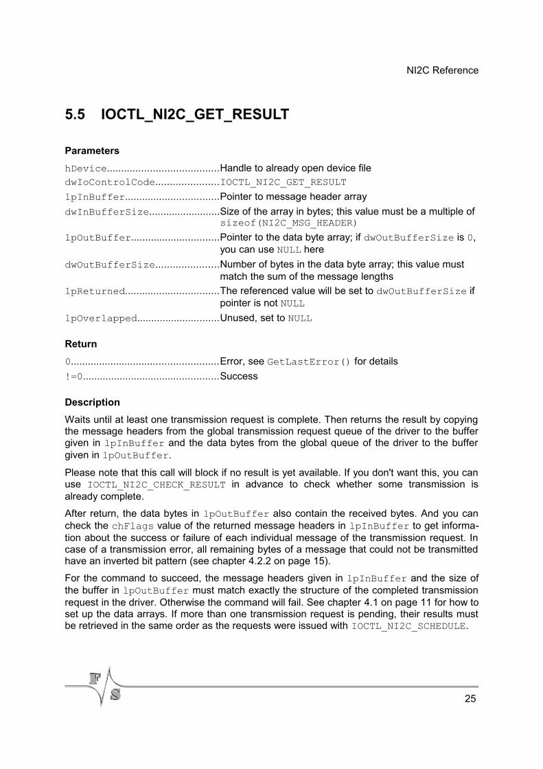
5.5 IOCTL_NI2C_GET_RESULT
Parameters
hDevice.......................................Handle to already open device filedwIoControlCode......................IOCTL_NI2C_GET_RESULT
lpInBuffer.................................Pointer to message header array
dwInBufferSize.........................Size of the array in bytes; this value must be a multiple of sizeof(NI2C_MSG_HEADER)
lpOutBuffer...............................Pointer to the data byte array; if dwOutBufferSize is 0, you can use NULL here
dwOutBufferSize......................Number of bytes in the data byte array; this value must match the sum of the message lengths
lpReturned.................................The referenced value will be set to dwOutBufferSize if pointer is not NULL
lpOverlapped.............................Unused, set to NULL
Return
0....................................................Error, see GetLastError() for details
!=0................................................Success
Description
Waits until at least one transmission request is complete. Then returns the result by copyingthe message headers from the global transmission request queue of the driver to the buffergiven in lpInBuffer and the data bytes from the global queue of the driver to the buffergiven in lpOutBuffer.
Please note that this call will block if no result is yet available. If you don't want this, you canuse IOCTL_NI2C_CHECK_RESULT in advance to check whether some transmission isalready complete.
After return, the data bytes in lpOutBuffer also contain the received bytes. And you cancheck the chFlags value of the returned message headers in lpInBuffer to get informa-tion about the success or failure of each individual message of the transmission request. Incase of a transmission error, all remaining bytes of a message that could not be transmittedhave an inverted bit pattern (see chapter 4.2.2 on page 15).
For the command to succeed, the message headers given in lpInBuffer and the size ofthe buffer in lpOutBuffer must match exactly the structure of the completed transmissionrequest in the driver. Otherwise the command will fail. See chapter 4.1 on page 11 for how toset up the data arrays. If more than one transmission request is pending, their results mustbe retrieved in the same order as the requests were issued with IOCTL_NI2C_SCHEDULE.
25
NI2C Reference
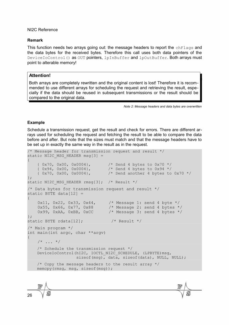
Remark
This function needs two arrays going out: the message headers to report the chFlags andthe data bytes for the received bytes. Therefore this call uses both data pointers of theDeviceIoControl() as OUT pointers, lpInBuffer and lpOutBuffer. Both arrays mustpoint to alterable memory!
Attention!
Both arrays are completely rewritten and the original content is lost! Therefore it is recom-mended to use different arrays for scheduling the request and retrieving the result, espe-cially if the data should be reused in subsequent transmissions or the result should becompared to the original data.
Note 2: Message headers and data bytes are overwritten
Example
Schedule a transmission request, get the result and check for errors. There are different ar-rays used for scheduling the request and fetching the result to be able to compare the databefore and after. But note that the sizes must match and that the message headers have tobe set up in exactly the same way in the result as in the request.
/* Message header for transmission request and result */static NI2C_MSG_HEADER msg[3] ={ { 0x70, 0x00, 0x0004}, /* Send 4 bytes to 0x70 */ { 0x94, 0x00, 0x0004}, /* Send 4 bytes to 0x94 */ { 0x70, 0x00, 0x0004}, /* Send another 4 bytes to 0x70 */};static NI2C_MSG_HEADER rmsg[3]; /* Result */
/* Data bytes for transmission request and result */static BYTE data[12] ={ 0x11, 0x22, 0x33, 0x44, /* Message 1: send 4 byte */ 0x55, 0x66, 0x77, 0x88 /* Message 2: send 4 bytes */ 0x99, 0xAA, 0xBB, 0xCC /* Message 3: send 4 bytes */};static BYTE rdata[12]; /* Result */
/* Main program */int main(int argc, char **argv){ /* ... */
/* Schedule the transmission request */ DeviceIoControl(hI2C, IOCTL_NI2C_SCHEDULE, (LPBYTE)msg, sizeof(msg), data, sizeof(data), NULL, NULL);
/* Copy the message headers to the result array */ memcpy(rmsg, msg, sizeof(msg));
26
NI2C Reference
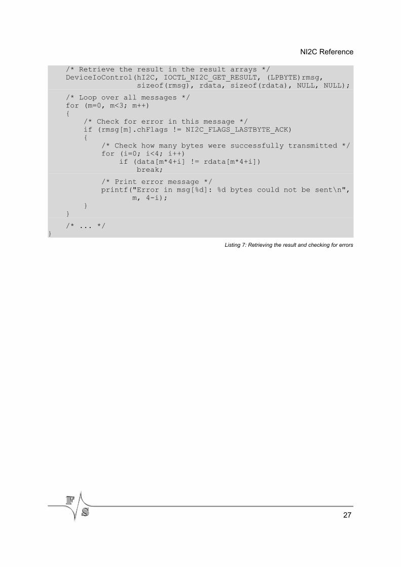
/* Retrieve the result in the result arrays */ DeviceIoControl(hI2C, IOCTL_NI2C_GET_RESULT, (LPBYTE)rmsg, sizeof(rmsg), rdata, sizeof(rdata), NULL, NULL);
/* Loop over all messages */ for (m=0, m<3; m++) { /* Check for error in this message */ if (rmsg[m].chFlags != NI2C_FLAGS_LASTBYTE_ACK) { /* Check how many bytes were successfully transmitted */ for (i=0; i<4; i++) if (data[m*4+i] != rdata[m*4+i]) break;
/* Print error message */ printf("Error in msg[%d]: %d bytes could not be sent\n", m, 4-i); } }
/* ... */}
Listing 7: Retrieving the result and checking for errors
27
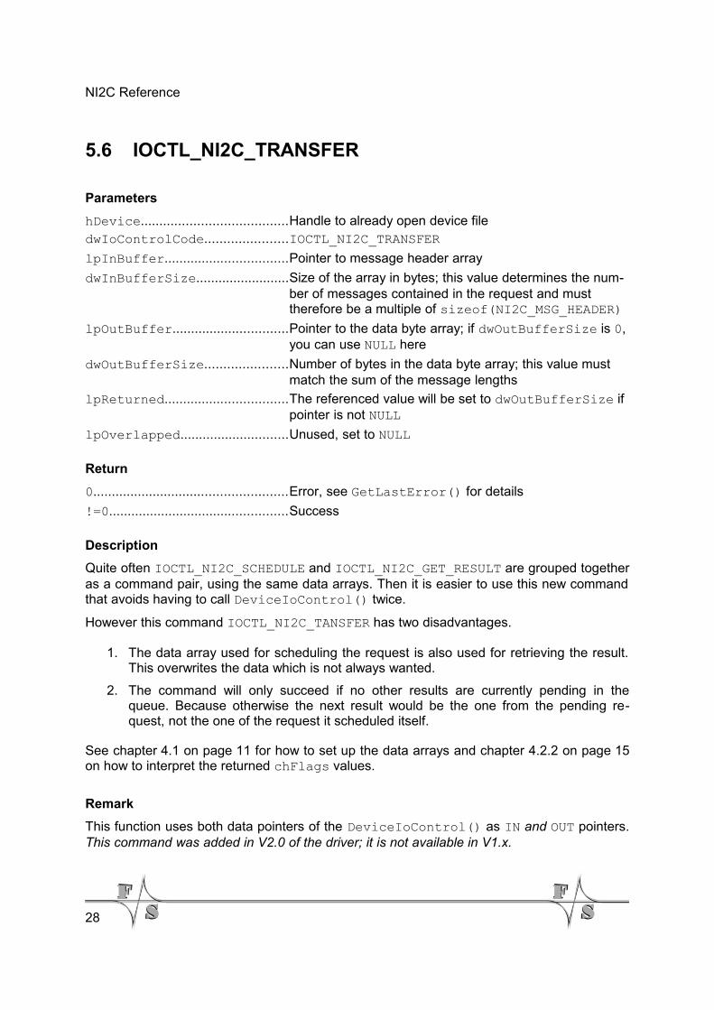
NI2C Reference
5.6 IOCTL_NI2C_TRANSFER
Parameters
hDevice.......................................Handle to already open device filedwIoControlCode......................IOCTL_NI2C_TRANSFER
lpInBuffer.................................Pointer to message header array
dwInBufferSize.........................Size of the array in bytes; this value determines the num-ber of messages contained in the request and must therefore be a multiple of sizeof(NI2C_MSG_HEADER)
lpOutBuffer...............................Pointer to the data byte array; if dwOutBufferSize is 0, you can use NULL here
dwOutBufferSize......................Number of bytes in the data byte array; this value must match the sum of the message lengths
lpReturned.................................The referenced value will be set to dwOutBufferSize if pointer is not NULL
lpOverlapped.............................Unused, set to NULL
Return
0....................................................Error, see GetLastError() for details
!=0................................................Success
Description
Quite often IOCTL_NI2C_SCHEDULE and IOCTL_NI2C_GET_RESULT are grouped togetheras a command pair, using the same data arrays. Then it is easier to use this new commandthat avoids having to call DeviceIoControl() twice.
However this command IOCTL_NI2C_TANSFER has two disadvantages.
1. The data array used for scheduling the request is also used for retrieving the result.This overwrites the data which is not always wanted.
2. The command will only succeed if no other results are currently pending in thequeue. Because otherwise the next result would be the one from the pending re-quest, not the one of the request it scheduled itself.
See chapter 4.1 on page 11 for how to set up the data arrays and chapter 4.2.2 on page 15on how to interpret the returned chFlags values.
Remark
This function uses both data pointers of the DeviceIoControl() as IN and OUT pointers.This command was added in V2.0 of the driver; it is not available in V1.x.
28
NI2C Reference
Example
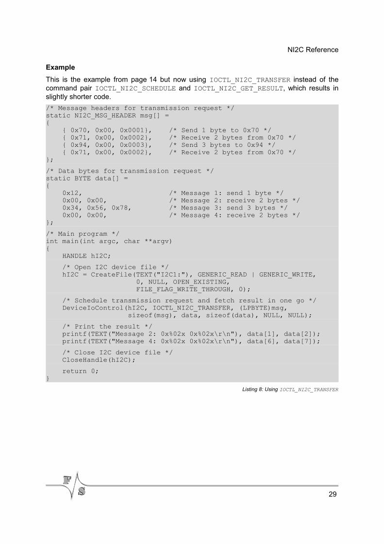
This is the example from page 14 but now using IOCTL_NI2C_TRANSFER instead of thecommand pair IOCTL_NI2C_SCHEDULE and IOCTL_NI2C_GET_RESULT, which results inslightly shorter code.
/* Message headers for transmission request */static NI2C_MSG_HEADER msg[] ={ { 0x70, 0x00, 0x0001}, /* Send 1 byte to 0x70 */ { 0x71, 0x00, 0x0002}, /* Receive 2 bytes from 0x70 */ { 0x94, 0x00, 0x0003}, /* Send 3 bytes to 0x94 */ { 0x71, 0x00, 0x0002}, /* Receive 2 bytes from 0x70 */};
/* Data bytes for transmission request */static BYTE data[] ={ 0x12, /* Message 1: send 1 byte */ 0x00, 0x00, /* Message 2: receive 2 bytes */ 0x34, 0x56, 0x78, /* Message 3: send 3 bytes */ 0x00, 0x00, /* Message 4: receive 2 bytes */};
/* Main program */int main(int argc, char **argv){ HANDLE hI2C;
/* Open I2C device file */ hI2C = CreateFile(TEXT("I2C1:"), GENERIC_READ | GENERIC_WRITE, 0, NULL, OPEN_EXISTING, FILE_FLAG_WRITE_THROUGH, 0);
/* Schedule transmission request and fetch result in one go */ DeviceIoControl(hI2C, IOCTL_NI2C_TRANSFER, (LPBYTE)msg, sizeof(msg), data, sizeof(data), NULL, NULL);
/* Print the result */ printf(TEXT("Message 2: 0x%02x 0x%02x\r\n"), data[1], data[2]); printf(TEXT("Message 4: 0x%02x 0x%02x\r\n"), data[6], data[7]);
/* Close I2C device file */ CloseHandle(hI2C);
return 0;}
Listing 8: Using IOCTL_NI2C_TRANSFER
29
NI2C Reference
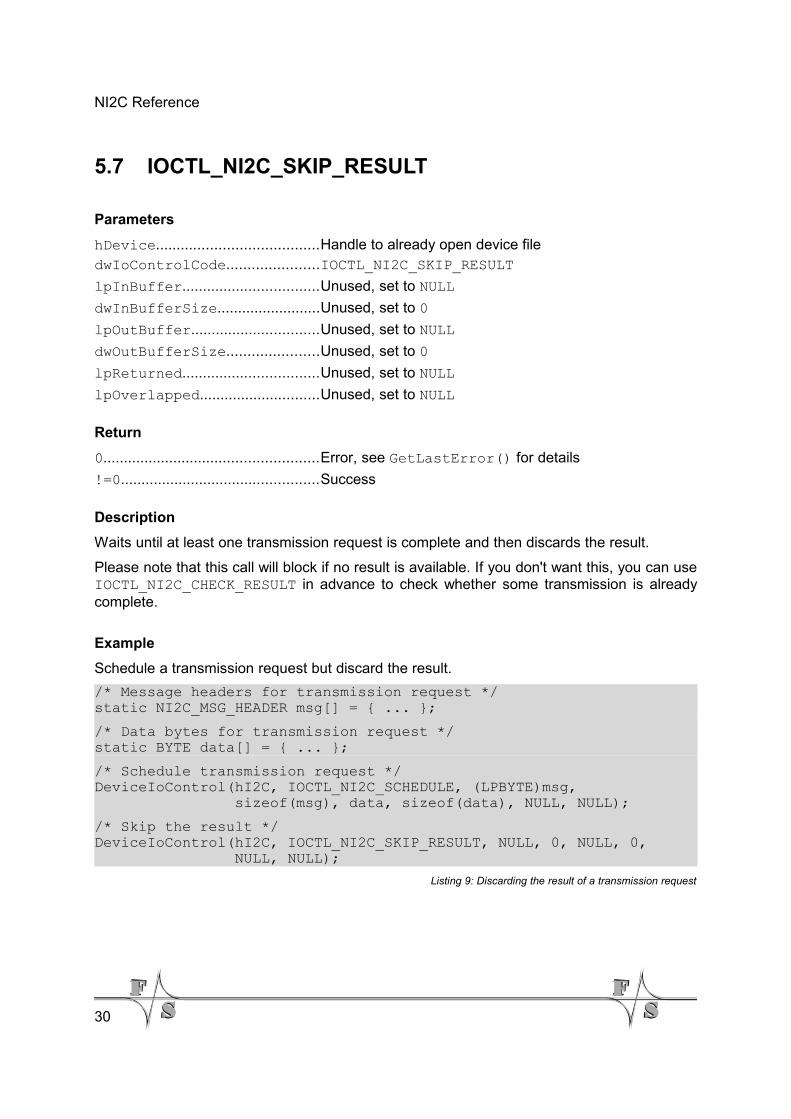
5.7 IOCTL_NI2C_SKIP_RESULT
Parameters
hDevice.......................................Handle to already open device filedwIoControlCode......................IOCTL_NI2C_SKIP_RESULT
lpInBuffer.................................Unused, set to NULL
dwInBufferSize.........................Unused, set to 0
lpOutBuffer...............................Unused, set to NULL
dwOutBufferSize......................Unused, set to 0
lpReturned.................................Unused, set to NULL
lpOverlapped.............................Unused, set to NULL
Return
0....................................................Error, see GetLastError() for details
!=0................................................Success
Description
Waits until at least one transmission request is complete and then discards the result.
Please note that this call will block if no result is available. If you don't want this, you can useIOCTL_NI2C_CHECK_RESULT in advance to check whether some transmission is alreadycomplete.
Example
Schedule a transmission request but discard the result.
/* Message headers for transmission request */static NI2C_MSG_HEADER msg[] = { ... };
/* Data bytes for transmission request */static BYTE data[] = { ... };
/* Schedule transmission request */DeviceIoControl(hI2C, IOCTL_NI2C_SCHEDULE, (LPBYTE)msg, sizeof(msg), data, sizeof(data), NULL, NULL);
/* Skip the result */DeviceIoControl(hI2C, IOCTL_NI2C_SKIP_RESULT, NULL, 0, NULL, 0, NULL, NULL);
Listing 9: Discarding the result of a transmission request
30
NI2C Reference
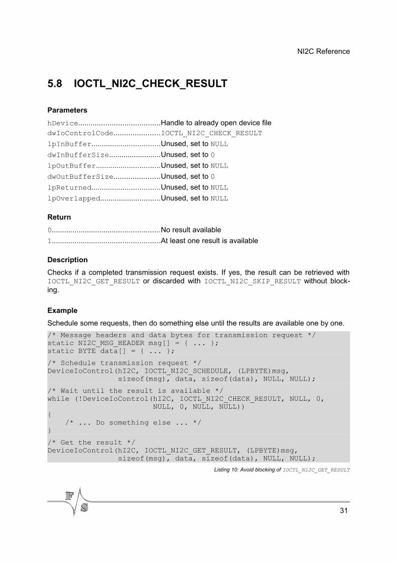
5.8 IOCTL_NI2C_CHECK_RESULT
Parameters
hDevice.......................................Handle to already open device filedwIoControlCode......................IOCTL_NI2C_CHECK_RESULT
lpInBuffer.................................Unused, set to NULL
dwInBufferSize.........................Unused, set to 0
lpOutBuffer...............................Unused, set to NULL
dwOutBufferSize......................Unused, set to 0
lpReturned.................................Unused, set to NULL
lpOverlapped.............................Unused, set to NULL
Return
0....................................................No result available
1....................................................At least one result is available
Description
Checks if a completed transmission request exists. If yes, the result can be retrieved withIOCTL_NI2C_GET_RESULT or discarded with IOCTL_NI2C_SKIP_RESULT without block-ing.
Example
Schedule some requests, then do something else until the results are available one by one.
/* Message headers and data bytes for transmission request */static NI2C_MSG_HEADER msg[] = { ... };static BYTE data[] = { ... };
/* Schedule transmission request */DeviceIoControl(hI2C, IOCTL_NI2C_SCHEDULE, (LPBYTE)msg, sizeof(msg), data, sizeof(data), NULL, NULL);
/* Wait until the result is available */while (!DeviceIoControl(hI2C, IOCTL_NI2C_CHECK_RESULT, NULL, 0, NULL, 0, NULL, NULL)){ /* ... Do something else ... */}
/* Get the result */DeviceIoControl(hI2C, IOCTL_NI2C_GET_RESULT, (LPBYTE)msg, sizeof(msg), data, sizeof(data), NULL, NULL);
Listing 10: Avoid blocking of IOCTL_NI2C_GET_RESULT
31
NI2C Reference
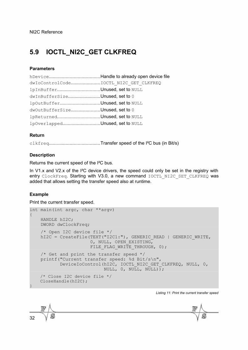
5.9 IOCTL_NI2C_GET CLKFREQ
Parameters
hDevice.......................................Handle to already open device filedwIoControlCode......................IOCTL_NI2C_GET_CLKFREQ
lpInBuffer.................................Unused, set to NULL
dwInBufferSize.........................Unused, set to 0
lpOutBuffer...............................Unused, set to NULL
dwOutBufferSize......................Unused, set to 0
lpReturned.................................Unused, set to NULL
lpOverlapped.............................Unused, set to NULL
Return
clkfreq.......................................Transfer speed of the I²C bus (in Bit/s)
Description
Returns the current speed of the I²C bus.
In V1.x and V2.x of the I²C device drivers, the speed could only be set in the registry withentry ClockFreq. Starting with V3.0, a new command IOCTL_NI2C_SET_CLKFREQ wasadded that allows setting the transfer speed also at runtime.
Example
Print the current transfer speed.
int main(int argc, char **argv){ HANDLE hI2C; DWORD dwClockFreq;
/* Open I2C device file */ hI2C = CreateFile(TEXT("I2C1:"), GENERIC_READ | GENERIC_WRITE, 0, NULL, OPEN_EXISTING, FILE_FLAG_WRITE_THROUGH, 0);
/* Get and print the transfer speed */ printf("Current transfer speed: %d Bit/s\n", DeviceIoControl(hI2C, IOCTL_NI2C_GET_CLKFREQ, NULL, 0, NULL, 0, NULL, NULL));
/* Close I2C device file */ CloseHandle(hI2C);}
Listing 11: Print the current transfer speed
32
NI2C Reference
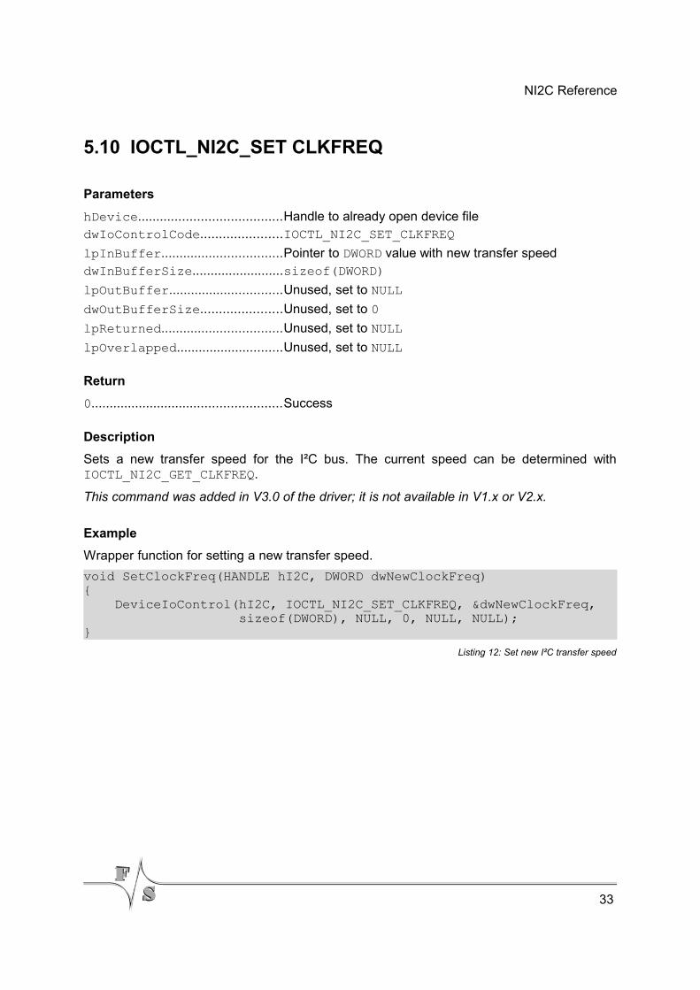
5.10 IOCTL_NI2C_SET CLKFREQ
Parameters
hDevice.......................................Handle to already open device filedwIoControlCode......................IOCTL_NI2C_SET_CLKFREQ
lpInBuffer.................................Pointer to DWORD value with new transfer speeddwInBufferSize.........................sizeof(DWORD)
lpOutBuffer...............................Unused, set to NULL
dwOutBufferSize......................Unused, set to 0
lpReturned.................................Unused, set to NULL
lpOverlapped.............................Unused, set to NULL
Return
0....................................................Success
Description
Sets a new transfer speed for the I²C bus. The current speed can be determined withIOCTL_NI2C_GET_CLKFREQ.
This command was added in V3.0 of the driver; it is not available in V1.x or V2.x.
Example
Wrapper function for setting a new transfer speed.
void SetClockFreq(HANDLE hI2C, DWORD dwNewClockFreq){ DeviceIoControl(hI2C, IOCTL_NI2C_SET_CLKFREQ, &dwNewClockFreq, sizeof(DWORD), NULL, 0, NULL, NULL);}
Listing 12: Set new I²C transfer speed
33
NI2C Reference
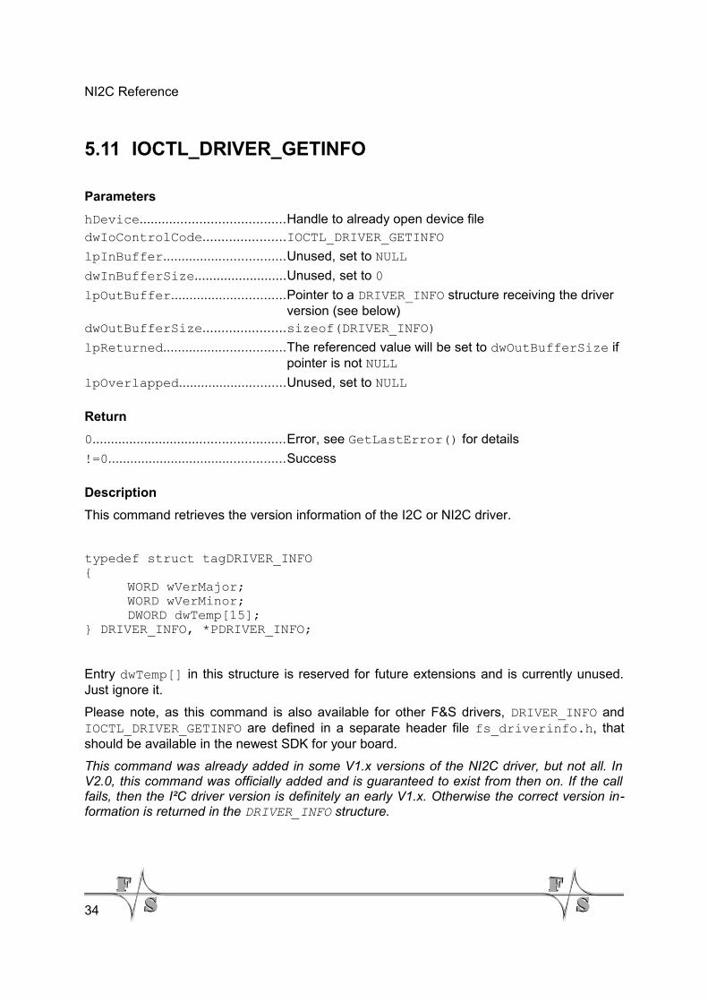
5.11 IOCTL_DRIVER_GETINFO
Parameters
hDevice.......................................Handle to already open device filedwIoControlCode......................IOCTL_DRIVER_GETINFO
lpInBuffer.................................Unused, set to NULL
dwInBufferSize.........................Unused, set to 0
lpOutBuffer...............................Pointer to a DRIVER_INFO structure receiving the driver version (see below)
dwOutBufferSize......................sizeof(DRIVER_INFO)
lpReturned.................................The referenced value will be set to dwOutBufferSize if pointer is not NULL
lpOverlapped.............................Unused, set to NULL
Return
0....................................................Error, see GetLastError() for details
!=0................................................Success
Description
This command retrieves the version information of the I2C or NI2C driver.
typedef struct tagDRIVER_INFO{
WORD wVerMajor;WORD wVerMinor;DWORD dwTemp[15];
} DRIVER_INFO, *PDRIVER_INFO;
Entry dwTemp[] in this structure is reserved for future extensions and is currently unused.Just ignore it.
Please note, as this command is also available for other F&S drivers, DRIVER_INFO andIOCTL_DRIVER_GETINFO are defined in a separate header file fs_driverinfo.h, thatshould be available in the newest SDK for your board.
This command was already added in some V1.x versions of the NI2C driver, but not all. InV2.0, this command was officially added and is guaranteed to exist from then on. If the callfails, then the I²C driver version is definitely an early V1.x. Otherwise the correct version in-formation is returned in the DRIVER_INFO structure.
34
NI2C Reference
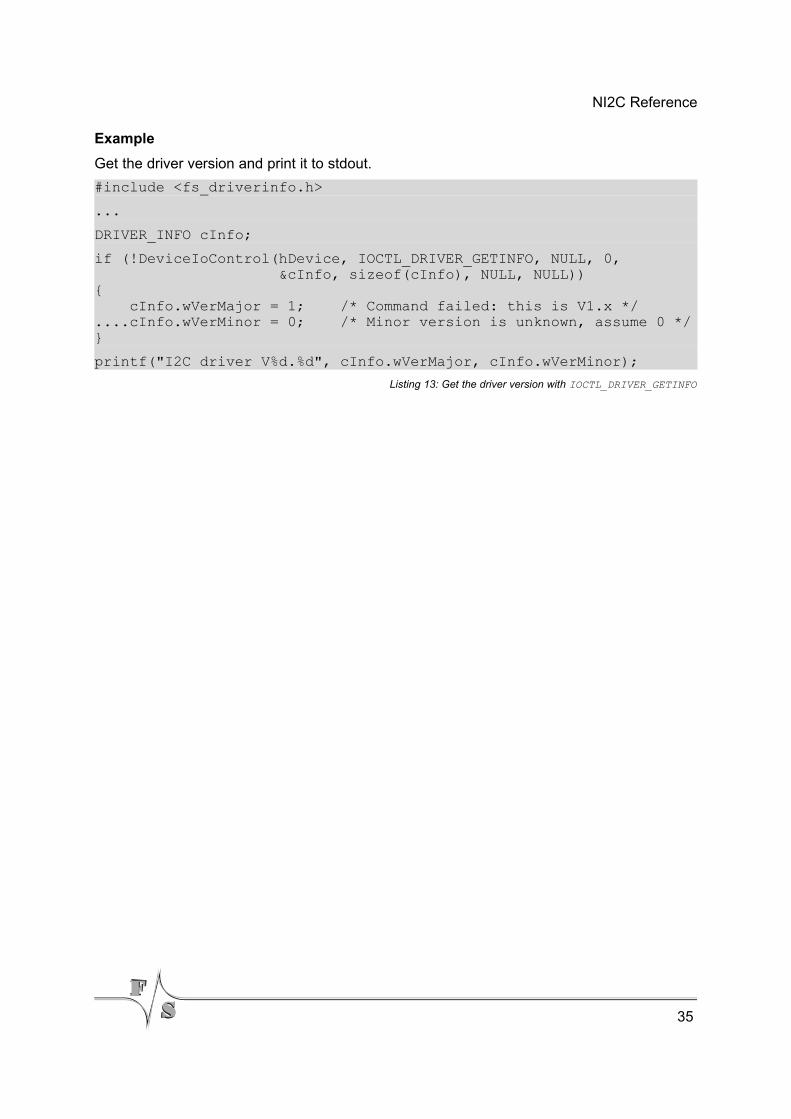
Example
Get the driver version and print it to stdout.
#include <fs_driverinfo.h>
...
DRIVER_INFO cInfo;
if (!DeviceIoControl(hDevice, IOCTL_DRIVER_GETINFO, NULL, 0, &cInfo, sizeof(cInfo), NULL, NULL)){ cInfo.wVerMajor = 1; /* Command failed: this is V1.x */....cInfo.wVerMinor = 0; /* Minor version is unknown, assume 0 */}
printf("I2C driver V%d.%d", cInfo.wVerMajor, cInfo.wVerMinor);
Listing 13: Get the driver version with IOCTL_DRIVER_GETINFO
35
Header File ni2cio.h
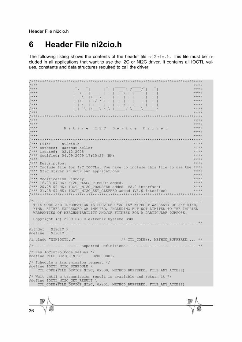
6 Header File ni2cio.hThe following listing shows the contents of the header file ni2cio.h. This file must be in-cluded in all applications that want to use the I2C or NI2C driver. It contains all IOCTL val-ues, constants and data structures required to call the driver.
/*****************************************************************************//*** _ _ _ _____ ____ _ _ ***//*** | \ | | | | | __ \ / ___/ | | | ***//*** | \ | | ___ _| |_| | \ | | | | | | ***//*** | \| |/ _ \_ _| | | | | | | | | ***//*** | |\ | |/_/ | | | | | | | | | | | ***//*** | | \ | |__ | | | |__/ | |___| |__| | ***//*** |_| \_|\___\ \_\ |_____/ \____\______/ ***//*** ***//*****************************************************************************//*** ***//*** ***//*** N a t i v e I 2 C D e v i c e D r i v e r ***//*** ***//*** ***//*****************************************************************************//*** File: ni2cio.h ***//*** Authors: Hartmut Keller ***//*** Created: 02.12.2005 ***//*** Modified: 04.09.2009 17:10:25 (HK) ***//*** ***//*** Description: ***//*** Include file for I2C IOCTLs. You have to include this file to use the ***//*** NI2C driver in your own applications. ***//*** ***//*** Modification History: ***//*** 16.03.07 HK: NI2C_FLAGS_TIMEOUT added. ***//*** 20.05.09 HK: IOCTL_NI2C_TRANSFER added (V2.0 interface) ***//*** 21.05.09 HK: IOCTL_NI2C_SET_CLKFREQ added (V3.0 interface) ***//*****************************************************************************/
/*----------------------------------------------------------------------------- THIS CODE AND INFORMATION IS PROVIDED "AS IS" WITHOUT WARRANTY OF ANY KIND, KIND, EITHER EXPRESSED OR IMPLIED, INCLUDING BUT NOT LIMITED TO THE IMPLIED WARRANTIES OF MERCHANTABILITY AND/OR FITNESS FOR A PARTICULAR PURPOSE.
Copyright (c) 2009 F&S Elektronik Systeme GmbH-----------------------------------------------------------------------------*/
#ifndef __NI2CIO_H__#define __NI2CIO_H__
#include "WINIOCTL.h" /* CTL_CODE(), METHOD_BUFFERED,... */
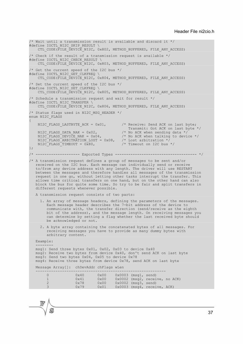
/* -------------------- Exported Definitions ------------------------------- */
/* New IOControlCode values */#define FILE_DEVICE_NI2C 0x00008037
/* Schedule a transmission request */#define IOCTL_NI2C_SCHEDULE \ CTL_CODE(FILE_DEVICE_NI2C, 0x800, METHOD_BUFFERED, FILE_ANY_ACCESS)
/* Wait until a transmission result is available and return it */#define IOCTL_NI2C_GET_RESULT \ CTL_CODE(FILE_DEVICE_NI2C, 0x801, METHOD_BUFFERED, FILE_ANY_ACCESS)
36
Header File ni2cio.h
/* Wait until a transmission result is available and discard it */#define IOCTL_NI2C_SKIP_RESULT \ CTL_CODE(FILE_DEVICE_NI2C, 0x802, METHOD_BUFFERED, FILE_ANY_ACCESS)
/* Check if the result of a transmission request is available */#define IOCTL_NI2C_CHECK_RESULT \ CTL_CODE(FILE_DEVICE_NI2C, 0x803, METHOD_BUFFERED, FILE_ANY_ACCESS)
/* Get the current speed of the I2C bus */#define IOCTL_NI2C_GET_CLKFREQ \ CTL_CODE(FILE_DEVICE_NI2C, 0x804, METHOD_BUFFERED, FILE_ANY_ACCESS)
/* Set the current speed of the I2C bus */#define IOCTL_NI2C_SET_CLKFREQ \ CTL_CODE(FILE_DEVICE_NI2C, 0x805, METHOD_BUFFERED, FILE_ANY_ACCESS)
/* Schedule a transmission request and wait for result */#define IOCTL_NI2C_TRANSFER \ CTL_CODE(FILE_DEVICE_NI2C, 0x806, METHOD_BUFFERED, FILE_ANY_ACCESS)
/* Status flags used in NI2C_MSG_HEADER */enum NI2C_FLAGS{ NI2C_FLAGS_LASTBYTE_ACK = 0x01, /* Receive: Send ACK on last byte; Transmit: Got ACK on last byte */ NI2C_FLAGS_DATA_NAK = 0x02, /* No ACK when sending data */ NI2C_FLAGS_DEVICE_NAK = 0x04, /* No ACK when talking to device */ NI2C_FLAGS_ARBITRATION_LOST = 0x08, /* Lost arbitration */ NI2C_FLAGS_TIMEOUT = 0x80, /* Timeout on I2C bus */};
/* -------------------- Exported Types ------------------------------------- */
/* A transmission request defines a group of messages to be sent and/or received on the I2C bus. Each message can individually send or receive to/from any device address with any length. The driver will use RESTART between the messages and therefore handles all messages of the transmission request in one go, without letting other tasks interrupt the transfer. This allows time critical transfers on one hand, but on the other hand can also block the bus for quite some time. So try to be fair and split transfers in different requests whenever possible.
A transmission request consists of two parts:
1. An array of message headers, defining the parameters of the messages. Each message header describes the 7-bit address of the device to communicate with, the transfer direction (send/receive as the eighth bit of the address), and the message length. On receiving messages you can determine by setting a flag whether the last received byte should be acknowledged or not.
2. A byte array containing the concatenated bytes of all messages. For receiving messages you have to provide as many dummy bytes with arbitrary content.
Example: -------- msg1: Send three bytes 0x01, 0x02, 0x03 to device 0x40 msg2: Receive two bytes from device 0x40, don't send ACK on last byte msg3: Send two bytes 0x04, 0x05 to device 0x78 msg4: Receive three bytes from device 0x78, send ACK on last byte
Message Array[]: chDevAddr chFlags wLen ----------------------------------------------------------- 0 0x40 0x00 0x0003 (msg1, send) 1 0x41 0x00 0x0002 (msg2, receive, no ACK) 2 0x78 0x00 0x0002 (msg3, send) 3 0x79 0x01 0x0003 (msg4, receive, ACK)
37
Header File ni2cio.h
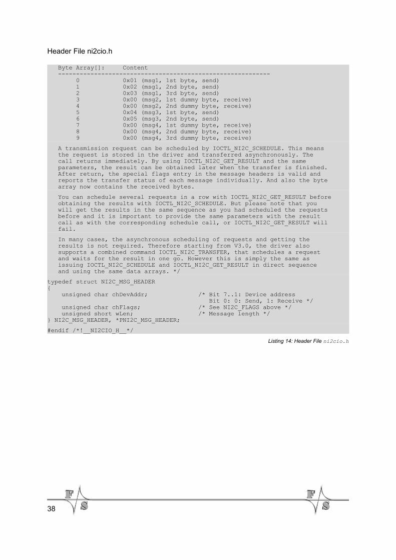
Byte Array[]: Content ----------------------------------------------------------- 0 0x01 (msg1, 1st byte, send) 1 0x02 (msg1, 2nd byte, send) 2 0x03 (msg1, 3rd byte, send) 3 0x00 (msg2, 1st dummy byte, receive) 4 0x00 (msg2, 2nd dummy byte, receive) 5 0x04 (msg3, 1st byte, send) 6 0x05 (msg3, 2nd byte, send) 7 0x00 (msg4, 1st dummy byte, receive) 8 0x00 (msg4, 2nd dummy byte, receive) 9 0x00 (msg4, 3rd dummy byte, receive)
A transmission request can be scheduled by IOCTL_NI2C_SCHEDULE. This means the request is stored in the driver and transferred asynchronously. The call returns immediately. By using IOCTL_NI2C_GET_RESULT and the same parameters, the result can be obtained later when the transfer is finished. After return, the special flags entry in the message headers is valid and reports the transfer status of each message individually. And also the byte array now contains the received bytes.
You can schedule several requests in a row with IOCTL_NI2C_GET_RESULT before obtaining the results with IOCTL_NI2C_SCHEDULE. But please note that you will get the results in the same sequence as you had scheduled the requests before and it is important to provide the same parameters with the result call as with the corresponding schedule call, or IOCTL_NI2C_GET_RESULT will fail.
In many cases, the asynchronous scheduling of requests and getting the results is not required. Therefore starting from V3.0, the driver also supports a combined command IOCTL_NI2C_TRANSFER, that schedules a request and waits for the result in one go. However this is simply the same as issuing IOCTL_NI2C_SCHEDULE and IOCTL_NI2C_GET_RESULT in direct sequence and using the same data arrays. */
typedef struct NI2C_MSG_HEADER{ unsigned char chDevAddr; /* Bit 7..1: Device address Bit 0: 0: Send, 1: Receive */ unsigned char chFlags; /* See NI2C_FLAGS above */ unsigned short wLen; /* Message length */} NI2C_MSG_HEADER, *PNI2C_MSG_HEADER;
#endif /*!__NI2CIO_H__*/
Listing 14: Header File ni2cio.h
38
Appendix
7 Appendix
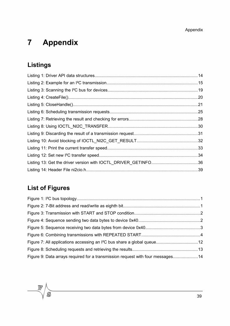
Listings
Listing 1: Driver API data structures......................................................................................14
Listing 2: Example for an I²C transmission............................................................................15
Listing 3: Scanning the I²C bus for devices...........................................................................19
Listing 4: CreateFile()............................................................................................................20
Listing 5: CloseHandle()........................................................................................................21
Listing 6: Scheduling transmission requests.........................................................................25
Listing 7: Retrieving the result and checking for errors.........................................................28
Listing 8: Using IOCTL_NI2C_TRANSFER...........................................................................30
Listing 9: Discarding the result of a transmission request.....................................................31
Listing 10: Avoid blocking of IOCTL_NI2C_GET_RESULT...................................................32
Listing 11: Print the current transfer speed...........................................................................33
Listing 12: Set new I²C transfer speed..................................................................................34
Listing 13: Get the driver version with IOCTL_DRIVER_GETINFO.......................................36
Listing 14: Header File ni2cio.h.............................................................................................39
List of Figures
Figure 1: I²C bus topology.......................................................................................................1
Figure 2: 7-Bit address and read/write as eighth bit................................................................1
Figure 3: Transmission with START and STOP condition.......................................................2
Figure 4: Sequence sending two data bytes to device 0x40...................................................2
Figure 5: Sequence receiving two data bytes from device 0x40.............................................3
Figure 6: Combining transmissions with REPEATED START.................................................4
Figure 7: All applications accessing an I²C bus share a global queue...................................12
Figure 8: Scheduling requests and retrieving the results......................................................13
Figure 9: Data arrays required for a transmission request with four messages....................14
39
Appendix
List of Tables
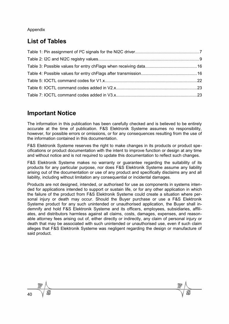
Table 1: Pin assignment of I²C signals for the NI2C driver......................................................7
Table 2: I2C and NI2C registry values....................................................................................9
Table 3: Possible values for entry chFlags when receiving data...........................................16
Table 4: Possible values for entry chFlags after transmission...............................................16
Table 5: IOCTL command codes for V1.x.............................................................................22
Table 6: IOCTL command codes added in V2.x....................................................................23
Table 7: IOCTL command codes added in V3.x....................................................................23
Important Notice
The information in this publication has been carefully checked and is believed to be entirelyaccurate at the time of publication. F&S Elektronik Systeme assumes no responsibility,however, for possible errors or omissions, or for any consequences resulting from the use ofthe information contained in this documentation.
F&S Elektronik Systeme reserves the right to make changes in its products or product spe-cifications or product documentation with the intent to improve function or design at any timeand without notice and is not required to update this documentation to reflect such changes.
F&S Elektronik Systeme makes no warranty or guarantee regarding the suitability of itsproducts for any particular purpose, nor does F&S Elektronik Systeme assume any liabilityarising out of the documentation or use of any product and specifically disclaims any and allliability, including without limitation any consequential or incidental damages.
Products are not designed, intended, or authorised for use as components in systems inten-ded for applications intended to support or sustain life, or for any other application in whichthe failure of the product from F&S Elektronik Systeme could create a situation where per-sonal injury or death may occur. Should the Buyer purchase or use a F&S ElektronikSysteme product for any such unintended or unauthorised application, the Buyer shall in-demnify and hold F&S Elektronik Systeme and its officers, employees, subsidiaries, affili-ates, and distributors harmless against all claims, costs, damages, expenses, and reason-able attorney fees arising out of, either directly or indirectly, any claim of personal injury ordeath that may be associated with such unintended or unauthorised use, even if such claimalleges that F&S Elektronik Systeme was negligent regarding the design or manufacture ofsaid product.
40