
IGNITION TRANSIENTS OF A GASEOUS CH4/O2 COAXIAL JET · Several experimental investigations of the...
7
ILASS 2008 Sep. 8-10, 2008, Como Lake, Italy IGNITION TRANSIENTS OF A GASEOUS CH4/O2 COAXIAL JET J. Sender, C. Manfletti, M. Oschwald, C. Pauly Deutsches Zentrum für Luft- und Raumfahrt Raumfahrtantriebe 74239 Hardthausen, Deutschland ABSTRACT Several experimental investigations of the ignition transient for liquid propellant rocket engines using H 2 /LOX have already been performed at the M3 test facility of DLR Lampoldshausen. To better understand the ignition and stability also of hydrocarbon/LOX driven engines new tests on the ignition of a gaseous O 2 / CH 4 coaxial jet for a range of nondimensional injection parameters, such as J, V ratio and p cc , were done. A combustion chamber (CC) with large lateral windows and small windows on both the top and bottom sides, equipped with a single coaxial injector, was used. Ignition was achieved by induced plasma break-down of a laser pulse focused downstream the injector. The ignition and stabilisation phase was visualized using Schlieren technique and recording of spontaneous fluorescence of intermediate existing OH radicals by high speed videography. Several phases during ignition have been found with specific phenomenology and which are dependent on parameters such as the ignition delay or mass fluxes of injected media. The pressure peak observed and its delay appears to be highly influenced by the injected masses of fuel and/or oxidizer before ignition. The CC pressure during steady state is an influent parameter to stabilize the flame near the injector. Flame lifting is observed to depend also on the velocity ratio of oxidizer and fuel, i.e. the mixing of both. INTRODUCTION Ignition is one of the most important phases during the start-up transients of a liquid rocket engine and has lead to failures in past launches (Ariane flights V15 and V18, involving the upper stage cryogenic HM7B engine). For upper stage engines, such as the European VINCI and Aestus engine, re-ignition is also of particular interest due to the multiple payload capability of the Ariane 5 launcher. Clearly for central and upper stage engine, ignition occurs under widely different conditions both in terms of pressure and temperature. These have an important impact on the atomisation of the propellants as various studies have shown. Several studies have been performed addressing transient ignition phenomena [7], [8],[9]. Amongst other objectives, these studies aimed at examining the spray behaviour of oxygen when combined to both H 2 and CH 4 in an attempt to investigate into potential differences between the two propellant couples spurred by an growing interest which alternative, so called “green”, propellants have seen. Although the propellant couple H 2 /O 2 is the most energetic, providing the highest Isp values, due to the low molecular weight of H 2 , many difficulties are encountered in their implementation. The best performing non-toxic alternatives to H 2 belong to the family of hydrocarbons, i.e. methane, propane and kerosene, and present several advantages like higher density or easier storability at ambient conditions (lower cooling efforts). Known disadvantages are their known tendency to produce soot reducing the ISP and a carbon layer at the cooling channel wall, which lowers the cooling efficiency. These disadvantages are minimised when methane is implemented [5]. Results related to ignition and combustion of methane and oxygen from the GCHO campaign are presented. The campaign was conceived so as to focus on ignition and flame stabilisation processes whilst at the same time providing detailed data to support numerical simulations of the injection, ignition, and combustion processes. The campaign implemented a gaseous O 2 /CH 4 coaxial jet, to better understand the ignition and stability of hydrocarbon/LOX driven engines for a range of non- dimensional injection parameters, such as J, V ratio and p cc . EXPERIMENTAL SET-UP Combustion chamber The GCHO campaign made use of the M3 Micro- combustor whose two most important features are the wide optical quartz windows which provide a complete optical access to the combustion chamber and the small windows located in the upper part of the chamber are used to allow the access of the converged laser beam to the chamber. The Micro-combustor is a horizontally mounted combustion chamber (CC). The section of the combustion chamber is rectangular with dimensions: 60 x 60 x 140 mm. Paper ID ILASS08-11-5 1
Transcript of IGNITION TRANSIENTS OF A GASEOUS CH4/O2 COAXIAL JET · Several experimental investigations of the...
ILASS 2008
Sep. 8-10, 2008, Como Lake, Italy
Paper ID ILASS08-A109
IGNITION TRANSIENTS OF A GASEOUS CH4/O2 COAXIAL JET
J. Sender, C. Manfletti, M. Oschwald, C. Pauly
Deutsches Zentrum für Luft- und Raumfahrt
Raumfahrtantriebe
74239 Hardthausen, Deutschland
ABSTRACT
Several experimental investigations of the ignition transient for liquid propellant rocket engines using H2/LOX have already
been performed at the M3 test facility of DLR Lampoldshausen. To better understand the ignition and stability also of
hydrocarbon/LOX driven engines new tests on the ignition of a gaseous O2 / CH4 coaxial jet for a range of nondimensional
injection parameters, such as J, Vratio and pcc , were done. A combustion chamber (CC) with large lateral windows and small
windows on both the top and bottom sides, equipped with a single coaxial injector, was used. Ignition was achieved by induced
plasma break-down of a laser pulse focused downstream the injector. The ignition and stabilisation phase was visualized using
Schlieren technique and recording of spontaneous fluorescence of intermediate existing OH radicals by high speed
videography. Several phases during ignition have been found with specific phenomenology and which are dependent on
parameters such as the ignition delay or mass fluxes of injected media. The pressure peak observed and its delay appears to be
highly influenced by the injected masses of fuel and/or oxidizer before ignition. The CC pressure during steady state is an
influent parameter to stabilize the flame near the injector. Flame lifting is observed to depend also on the velocity ratio of
oxidizer and fuel, i.e. the mixing of both.
INTRODUCTION
Ignition is one of the most important phases during the
start-up transients of a liquid rocket engine and has lead to
failures in past launches (Ariane flights V15 and V18,
involving the upper stage cryogenic HM7B engine). For upper
stage engines, such as the European VINCI and Aestus engine,
re-ignition is also of particular interest due to the multiple
payload capability of the Ariane 5 launcher. Clearly for central
and upper stage engine, ignition occurs under widely different
conditions both in terms of pressure and temperature. These
have an important impact on the atomisation of the propellants
as various studies have shown. Several studies have been
performed addressing transient ignition phenomena [7],
[8],[9]. Amongst other objectives, these studies aimed at
examining the spray behaviour of oxygen when combined to
both H2 and CH4 in an attempt to investigate into potential
differences between the two propellant couples spurred by an
growing interest which alternative, so called “green”,
propellants have seen. Although the propellant couple H2/O2 is
the most energetic, providing the highest Isp values, due to the
low molecular weight of H2, many difficulties are encountered
in their implementation. The best performing non-toxic
alternatives to H2 belong to the family of hydrocarbons, i.e.
methane, propane and kerosene, and present several
advantages like higher density or easier storability at
ambient conditions (lower cooling efforts). Known
disadvantages are their known tendency to produce soot
reducing the ISP and a carbon layer at the cooling channel
wall, which lowers the cooling efficiency. These
disadvantages are minimised when methane is implemented
[5].
Results related to ignition and combustion of methane and
oxygen from the GCHO campaign are presented. The
campaign was conceived so as to focus on ignition and flame
stabilisation processes whilst at the same time providing
detailed data to support numerical simulations of the injection,
ignition, and combustion processes.
The campaign implemented a gaseous O2/CH4 coaxial jet,
to better understand the ignition and stability of
hydrocarbon/LOX driven engines for a range of non-
dimensional injection parameters, such as J, Vratio and pcc.
EXPERIMENTAL SET-UP
Combustion chamber
The GCHO campaign made use of the M3 Micro-
combustor whose two most important features are the wide
optical quartz windows which provide a complete optical
access to the combustion chamber and the small windows
located in the upper part of the chamber are used to allow the
access of the converged laser beam to the chamber. The
Micro-combustor is a horizontally mounted combustion
chamber (CC). The section of the combustion chamber is
rectangular with dimensions: 60 x 60 x 140 mm.
Paper ID ILASS08-11-5
1
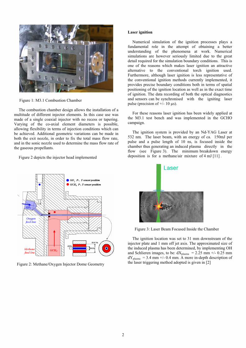
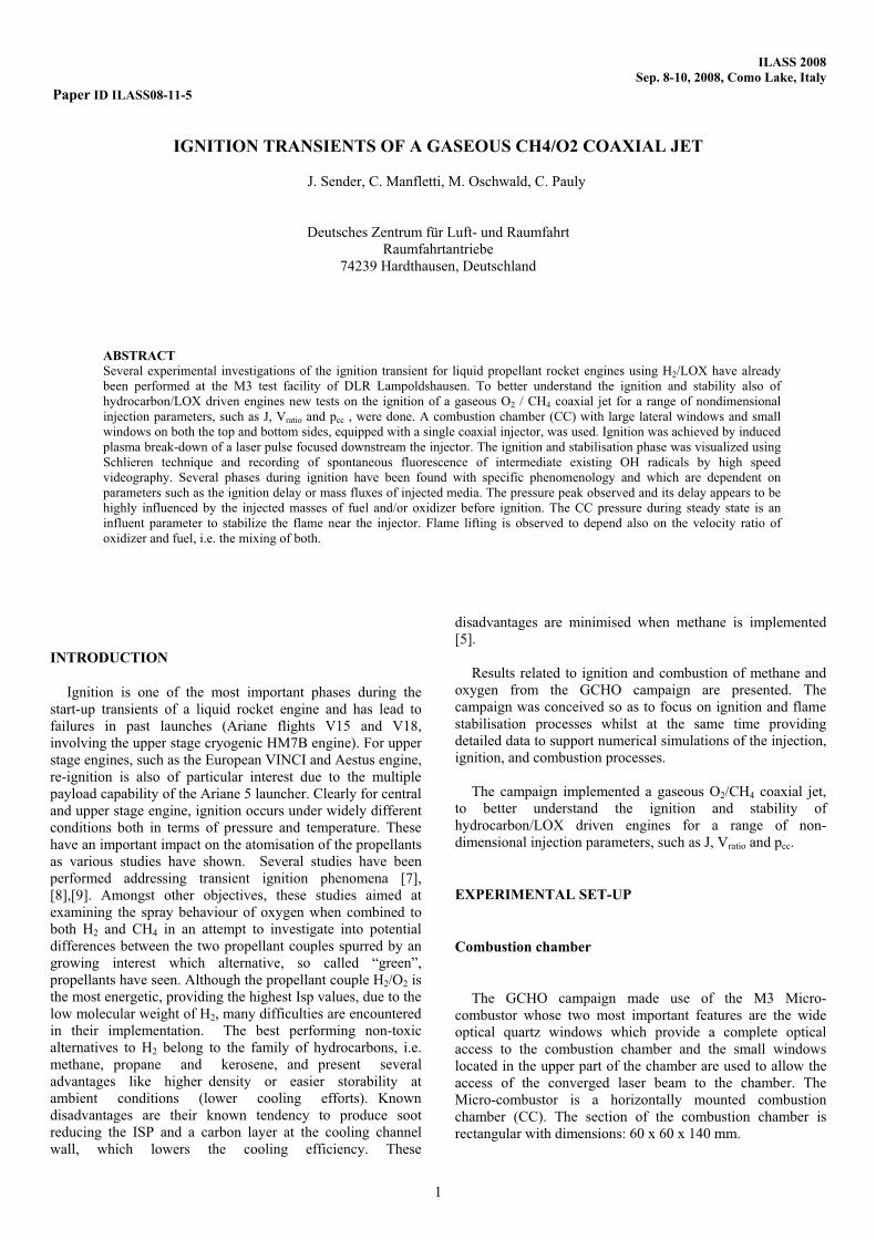
Figure 1: M3.1 Combustion Chamber
The combustion chamber design allows the installation of a
multitude of different injector elements. In this case use was
made of a single coaxial injector with no recess or tapering.
Varying of the co-axial element diameters is possible,
allowing flexibility in terms of injection conditions which can
be achieved. Additional geometric variations can be made in
both the exit nozzle, in order to fix the total mass flow rate,
and in the sonic nozzle used to determine the mass flow rate of
the gaseous propellants.
Figure 2 depicts the injector head implemented
Laser ignition
Numerical simulation of the ignition processes plays a
fundamental role in the attempt of obtaining a better
understanding of the phenomena at work. Numerical
simulations are however seriously limited due to the great
detail required for the simulation boundary conditions. This is
one of the reasons which makes laser ignition an attractive
alternative to the conventional torch ignition used.
Furthermore, although laser ignition is less representative of
the conventional ignition methods currently implemented, it
provides precise boundary conditions both in terms of spatial
positioning of the ignition location as well as in the exact time
of ignition. The data recording of both the optical diagnostics
and sensors can be synchronised with the igniting laser
pulse (precision of +/- 10 µs).
For these reasons laser ignition has been widely applied at
the M3.1 test bench and was implemented in the GCHO
campaign.
The ignition system is provided by an Nd-YAG Laser at
532 nm. The laser beam, with an energy of ca. 150mJ per
pulse and a pulse length of 10 ns, is focused inside the
chamber thus generating an induced plasma directly in the
flow (see Figure 3). The minimum breakdown energy
deposition is for a methane/air mixture of 4 mJ [11] .
The ignition location was set to 31 mm downstream of the
injector plate and 1 mm off jet axis. The approximated size of
the induced plasma has been determined, by implementing OH
and Schlieren images, to be: dXplasma = 2.25 mm +/- 0.25 mm
dYplasma = 3.4 mm +/- 0.4 mm. A more in-depth description of
the laser triggering method adopted is given in [2]Figure 2: Methane/Oxygen Injector Dome Geometry
Figure 3: Laser Beam Focused Inside the Chamber
2
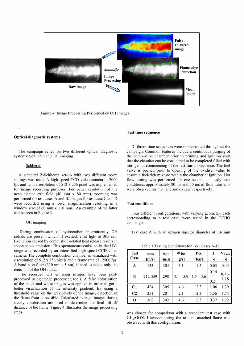
Figure 4: Image Processing Performed on OH Images
.
Optical diagnostic systems
The campaign relied on two different optical diagnostic
systems: Schlieren and OH imaging.
Schlieren
A standard Z-Schlieren set-up with two different zoom
settings was used. A high speed CCD video camera at 2000
fps and with a resolution of 512 x 256 pixel was implemented
for image recording purposes. For better resolution of the
near-injector exit field (40 mm x 80 mm), zooming was
performed for test cases A and B. Images for test case C and D
were recorded using a lower magnification resulting in a
window size of 60 mm x 110 mm. An example of the latter
can be seen in Figure 3.
OH imaging
During combustion of hydrocarbon intermittently OH
radials are present which, if excited, emit light at 305 nm.
Excitation caused by combustion-related heat release results in
spontaneous emission. This spontaneous emission in the UV-
range was recorded by an intensified high speed CCD video
camera. The complete combustion chamber is visualized with
a resolution of 512 x 256 pixels and a frame rate of 12500 fps.
A band-pass filter (310 nm ± 5 nm) is used to select only the
emission of the OH-radical.
The recorded OH emission images have been post-
processed using image processing tools. A false colorization
of the black and white images was applied in order to get a
better visualization of the intensity gradient. By using a
threshold value on the grey levels of the image, detection of
the flame front is possible. Calculated average images during
steady combustion are used to determine the final lift-off
distance of the flame. Figure 4 illustrates the image processing
steps.
Test time sequence
Different time sequences were implemented throughout the
campaign. Common features include a continuous purging of
the combustion chamber prior to priming and ignition such
that the chamber can be considered to be completed filled with
nitrogen at commencing of the test startup sequence. The fuel
valve is opened prior to opening of the oxidiser value to
ensure a fuel-rich mixture within the chamber at ignition. Hot
flow testing was performed for one second at steady-state
conditions, approximately 80 ms and 50 ms of flow transients
were observed for methane and oxygen respectively.
Test conditions
Four different configurations, with varying geometry, each
corresponding to a test case, were tested in the GCHO
campaign.
Test case A with an oxygen injector diameter of 1.6 mm
was chosen for comparison with a precedent test case with
GH2/GOX. However during the test, no attached flame was
observed with this configuration.
Table 1 Testing Conditions for Test Cases A-D
uCH4 uO2m tot Pcc J VRatioTest
Case [m/s] [m/s] [g/s] [bar] [-] [-]
A 133 304 3.1 1.5 0.03 0.44
B 212-359 298 3.1 – 5.9 1.5 – 3.6
0.14
-
0.21
0.71-
1.18
C1 424 305 4.6 2.3 1.06 1.39
C2 351 201 2.1 2.3 1.56 1.74
D 368 302 4.6 2.3 0.37 1.22
Image
Processing
False
coloured
image
Flame edge
detection
Mean
image
Raw image
3
Test cases B through D have been set up with an enlarged
diameter to enable a wider range of available oxygen injection
velocities.
In test case C (C1 & C2) the influence of the injection
velocity was studied in more detail using two different
combustion chamber nozzles, 4 mm and 6 mm diameter
respectively. The resulting injection conditions are given in
Table 1.
IGNITION PHENOMENOLOGY OF A GOX/GCH4
COAXIAL JET (GCHO CAMAPAIGN)
General remarks
Based on the evaluation of the OH and Schlieren images,
the existence of three different ignition scenarios has been
observed.
A non reliable ignition where the flame is blown out and
extinguished has been found and two successful other ignition
types: one with smooth evolution of the flame front and of the
chamber pressure, the other one with much stronger transient
phenomenology. Additional observations include three
different transient phases characterising the evolution of the
flame front for each of the reliable ignition scenarios. These
three phases are, in order of appearance: a blow down phase,
where the flame is blown downstream (or even extinguishes);
an expansion phase, where the flame increases in size and
intensity; and finally a stabilization phase, where the flame
stabilizes and is either detached or attached to the injector. The
duration of each phase depends on the combination of fluid
injection conditions and injector geometry. Typically, the
blow down phase lasted between 0.5 and 1.5 ms and the
expansion phase between 6 and 17 ms.
An important parameter determining to what extent each
phase is present and thus determining which ignition scenario
occurs is the time delay between opening of the propellant
valves and the laser pulse (“ignition delay”).
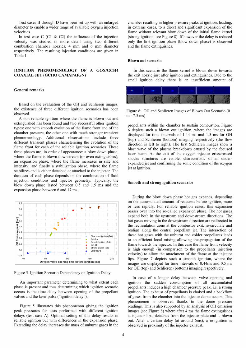
Figure 5 illustrates this phenomenon giving the ignition
peak pressures for tests performed with different ignition
delays (test case A). Optimal setting of this delay results in
reliable ignition but with differences in the expansion phase.
Extending the delay increases the mass of unburnt gases in the
chamber resulting in higher pressure peaks at ignition, leading,
in extreme cases, to a direct and significant expansion of the
flame without relevant blow down of the initial flame kernel
(strong ignition, see Figure 8). If however the delay is reduced
only the first ignition phase (blow down phase) is observed
and the flame extinguishes.
Blown out scenario
In this scenario the flame kernel is blown down towards
the exit nozzle just after ignition and extinguishes. Due to the
small ignition delay there is an insufficient amount of
propellants within the chamber to sustain combustion. Figure
6 depicts such a blown out ignition, where the images are
displayed for time intervals of 1.44 ms and 1.5 ms for OH
(top) and Schlieren (bottom) imaging respectively (the flow
direction is left to right). The first Schlieren images show a
blast wave of the plasma breakdown caused by the focused
laser beam. At the exit of the oxygen injector crisscrossed
shocks structures are visible, characteristic of an under-
expanded jet and confirming the sonic condition of the oxygen
jet at ignition.
Smooth and strong ignition scenarios
During the blow down phase hot gas expands, depending
on the accumulated amount of reactants before ignition, more
or less rapidly. For reliable ignition cases, this expansion
passes over into the so-called expansion phase. The hot gases
expand both in the upstream and downstream directions. The
hot gases moving in the downstream direction are redirected in
the recirculation zone at the combustor exit, re-circulate and
realign along the central propellant jet. The interaction of
these hot gases with the unburnt and colder propellants leads
to an efficient local mixing allowing the propagation of the
flame towards the injector. In this case the flame front velocity
is high enough (in comparison to the propellants injection
velocity) to allow the attachment of the flame at the injector
lips. Figure 7 depicts such a smooth ignition, where the
images are displayed for time intervals of 0.44ms and 0.5 ms
for OH (top) and Schlieren (bottom) imaging respectively.
In case of a longer delay between valve opening and
ignition the sudden consumption of all accumulated
propellants induces a high chamber pressure peak, i.e. a strong
ignition. The exhaust of propellants is choked and a backflow
of gases from the chamber into the injector dome occurs. This
phenomenon is observed thanks to the dome pressure
readings. This is also supported by an analysis of OH emission
images (see Figure 8) where after 4 ms the flame extinguishes
at injector lips, detaches from the injector plate and is blown
out. After a certain delay (at around 6ms), a re-ignition is
observed in proximity of the injector exhaust.
0.5
1.5
2.5
3.5
4.5
5.5
6.5
7.5
8.5
9.5
40 90 140 190 240
Oxygen valve opening time before ignition [ms]
CC
Pre
ssu
re p
eak [
bar]
Blow n out Ignition (BoI)
BoI-SmI
Smooth Ignition (SmI)
SmI-StI
Strong Ignition (StI)
Cold f low s
Figure 5 Ignition Scenario Dependency on Ignition Delay
Figure 6: OH and Schlieren Images of Blown Out Scenario (0
to ~7.5 ms)
4
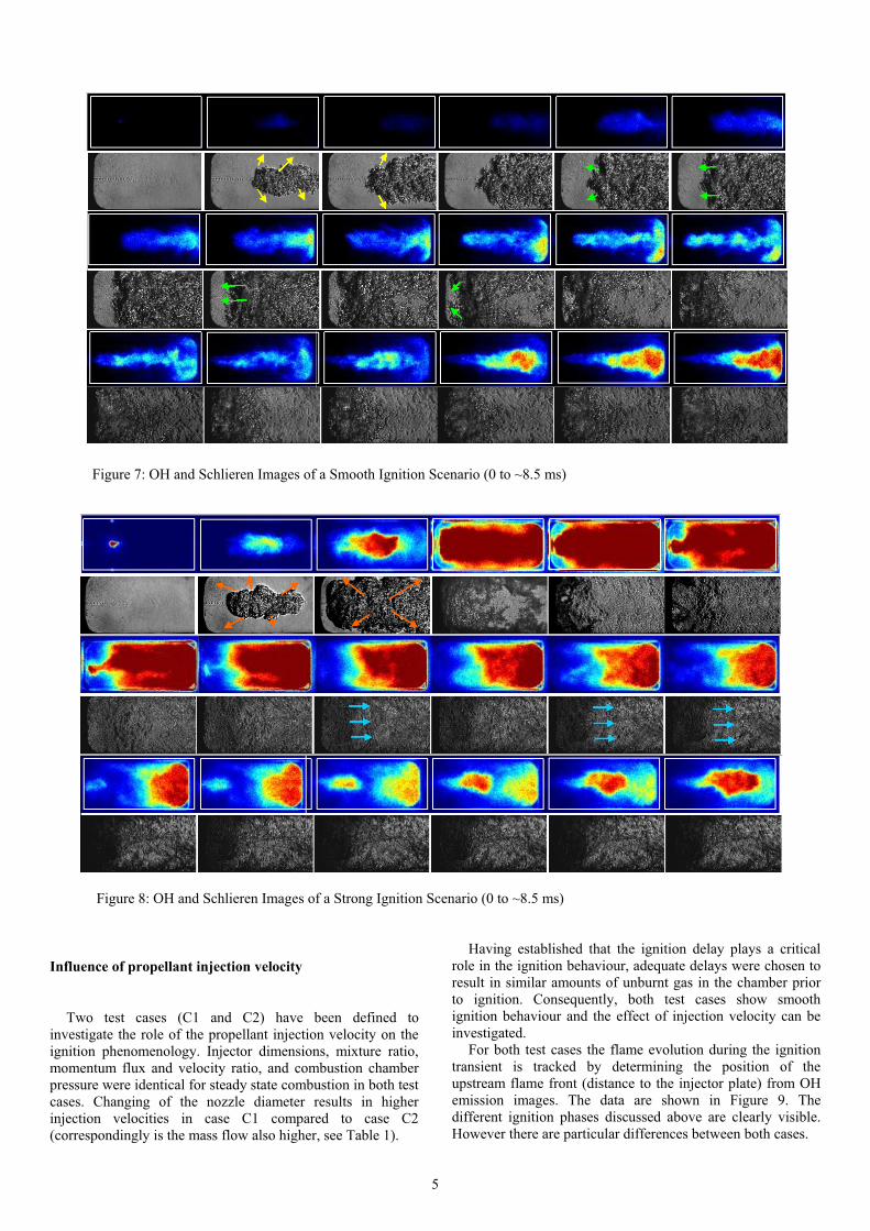
Figure 7: OH and Schlieren Images of a Smooth Ignition Scenario (0 to ~8.5 ms)
Figure 8: OH and Schlieren Images of a Strong Ignition Scenario (0 to ~8.5 ms)
Influence of propellant injection velocity
Two test cases (C1 and C2) have been defined to
investigate the role of the propellant injection velocity on the
ignition phenomenology. Injector dimensions, mixture ratio,
momentum flux and velocity ratio, and combustion chamber
pressure were identical for steady state combustion in both test
cases. Changing of the nozzle diameter results in higher
injection velocities in case C1 compared to case C2
(correspondingly is the mass flow also higher, see Table 1).
Having established that the ignition delay plays a critical
role in the ignition behaviour, adequate delays were chosen to
result in similar amounts of unburnt gas in the chamber prior
to ignition. Consequently, both test cases show smooth
ignition behaviour and the effect of injection velocity can be
investigated.
For both test cases the flame evolution during the ignition
transient is tracked by determining the position of the
upstream flame front (distance to the injector plate) from OH
emission images. The data are shown in Figure 9. The
different ignition phases discussed above are clearly visible.
However there are particular differences between both cases.
5
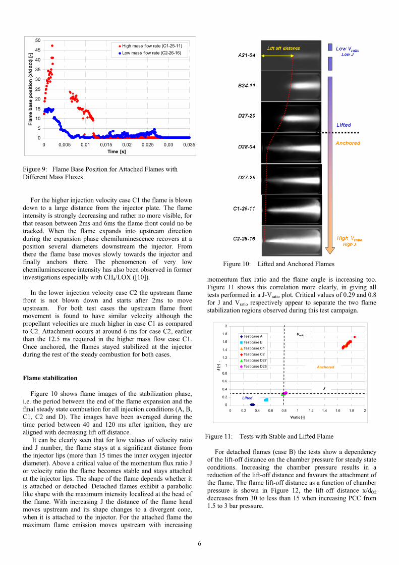
For the higher injection velocity case C1 the flame is blown
down to a large distance from the injector plate. The flame
intensity is strongly decreasing and rather no more visible, for
that reason between 2ms and 6ms the flame front could no be
tracked. When the flame expands into upstream direction
during the expansion phase chemiluminescence recovers at a
position several diameters downstream the injector. From
there the flame base moves slowly towards the injector and
finally anchors there. The phenomenon of very low
chemiluminescence intensity has also been observed in former
investigations especially with CH4/LOX ([10]).
In the lower injection velocity case C2 the upstream flame
front is not blown down and starts after 2ms to move
upstream. For both test cases the upstream flame front
movement is found to have similar velocity although the
propellant velocities are much higher in case C1 as compared
to C2. Attachment occurs at around 6 ms for case C2, earlier
than the 12.5 ms required in the higher mass flow case C1.
Once anchored, the flames stayed stabilized at the injector
during the rest of the steady combustion for both cases.
Flame stabilization
Figure 10 shows flame images of the stabilization phase,
i.e. the period between the end of the flame expansion and the
final steady state combustion for all injection conditions (A, B,
C1, C2 and D). The images have been averaged during the
time period between 40 and 120 ms after ignition, they are
aligned with decreasing lift off distance.
It can be clearly seen that for low values of velocity ratio
and J number, the flame stays at a significant distance from
the injector lips (more than 15 times the inner oxygen injector
diameter). Above a critical value of the momentum flux ratio J
or velocity ratio the flame becomes stable and stays attached
at the injector lips. The shape of the flame depends whether it
is attached or detached. Detached flames exhibit a parabolic
like shape with the maximum intensity localized at the head of
the flame. With increasing J the distance of the flame head
moves upstream and its shape changes to a divergent cone,
when it is attached to the injector. For the attached flame the
maximum flame emission moves upstream with increasing
momentum flux ratio and the flame angle is increasing too.
Figure 11 shows this correlation more clearly, in giving all
tests performed in a J-Vratio plot. Critical values of 0.29 and 0.8
for J and Vratio respectively appear to separate the two flame
stabilization regions observed during this test campaign.
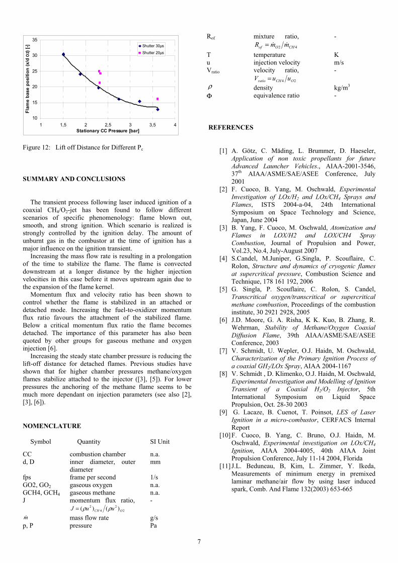
For detached flames (case B) the tests show a dependency
of the lift-off distance on the chamber pressure for steady state
conditions. Increasing the chamber pressure results in a
reduction of the lift-off distance and favours the attachment of
the flame. The flame lift-off distance as a function of chamber
pressure is shown in Figure 12, the lift-off distance x/dO2
decreases from 30 to less than 15 when increasing PCC from
1.5 to 3 bar pressure.
0
5
10
15
20
25
30
35
40
45
50
0 0,005 0,01 0,015 0,02 0,025 0,03 0,035
Time [s]
Fla
me
ba
se
po
sit
ion
(x
/dG
O2)
[-]
High mass flow rate (C1-25-11)
Low mass flow rate (C2-26-16)
Figure 9: Flame Base Position for Attached Flames with
Different Mass Fluxes
Figure 10: Lifted and Anchored Flames
Figure 11: Tests with Stable and Lifted Flame
0
0.2
0.4
0.6
0.8
1
1.2
1.4
1.6
1.8
2
0 0.2 0.4 0.6 0.8 1 1.2 1.4 1.6 1.8 2
Vratio [-]
J [
-] .
Test case A
Test case B
Test case C1
Test case C2
Test case D27
Test case D28 Anchored
Lifted
J
Vratio
6
SUMMARY AND CONCLUSIONS
The transient process following laser induced ignition of a
coaxial CH4/O2-jet has been found to follow different
scenarios of specific phenomenology: flame blown out,
smooth, and strong ignition. Which scenario is realized is
strongly controlled by the ignition delay. The amount of
unburnt gas in the combustor at the time of ignition has a
major influence on the ignition transient.
Increasing the mass flow rate is resulting in a prolongation
of the time to stabilize the flame. The flame is convected
downstream at a longer distance by the higher injection
velocities in this case before it moves upstream again due to
the expansion of the flame kernel.
Momentum flux and velocity ratio has been shown to
control whether the flame is stabilized in an attached or
detached mode. Increasing the fuel-to-oxidizer momentum
flux ratio favours the attachment of the stabilized flame.
Below a critical momentum flux ratio the flame becomes
detached. The importance of this parameter has also been
quoted by other groups for gaseous methane and oxygen
injection [6].
Increasing the steady state chamber pressure is reducing the
lift-off distance for detached flames. Previous studies have
shown that for higher chamber pressures methane/oxygen
flames stabilize attached to the injector ([3], [5]). For lower
pressures the anchoring of the methane flame seems to be
much more dependant on injection parameters (see also [2],
[3], [6]).
NOMENCLATURE
Symbol Quantity SI Unit
CC combustion chamber n.a.
d, D inner diameter, outer
diameter
mm
fps frame per second 1/s
GO2, GO2 gaseous oxygen n.a.
GCH4, GCH4 gaseous methane n.a.
J momentum flux ratio,
2
2
4
2 )()( OCH uuJ ρρ=-
m mass flow rate g/s
p, P pressure Pa
Rof mixture ratio,
42 CHOof mmR =-
T temperature K
u injection velocity m/s
Vratio velocity ratio,
24 OCHratio uuV =-
ρ density kg/m3
Φ equivalence ratio -
REFERENCES
[1] A. Götz, C. Mäding, L. Brummer, D. Haeseler,
Application of non toxic propellants for future
Advanced Launcher Vehicles., AIAA-2001-3546,
37th AIAA/ASME/SAE/ASEE Conference, July
2001
[2] F. Cuoco, B. Yang, M. Oschwald, Experimental
Investigation of LOx/H2 and LOx/CH4 Sprays and Flames, ISTS 2004-a-04, 24th International
Symposium on Space Technology and Science,
Japan, June 2004
[3] B. Yang, F. Cuoco, M. Oschwald, Atomization and Flames in LOX/H2 and LOX/CH4 Spray
Combustion, Journal of Propulsion and Power,
Vol.23, No.4, July-August 2007
[4] S.Candel, M.Juniper, G.Singla, P. Scouflaire, C.
Rolon, Structure and dynamics of cryogenic flames
at supercritical pressure, Combustion Science and
Technique, 178 161 192, 2006
[5] G. Singla, P. Scouflaire, C. Rolon, S. Candel,
Transcritical oxygen/transcritical or supercritical
methane combustion, Proceedings of the combustion
institute, 30 2921 2928, 2005
[6] J.D. Moore, G. A. Risha, K K. Kuo, B. Zhang, R.
Wehrman, Stability of Methane/Oxygen Coaxial
Diffusion Flame, 39th AIAA/ASME/SAE/ASEE
Conference, 2003
[7] V. Schmidt, U. Wepler, O.J. Haidn, M. Oschwald,
Characterization of the Primary Ignition Process of
a coaxial GH2/LOx Spray, AIAA 2004-1167
[8] V. Schmidt , D. Klimenko, O.J. Haidn, M. Oschwald,
Experimental Investigation and Modelling of Ignition Transient of a Coaxial H2/O2 Injector, 5th
International Symposium on Liquid Space
Propulsion, Oct. 28-30 2003
[9] G. Lacaze, B. Cuenot, T. Poinsot, LES of Laser Ignition in a micro-combustor, CERFACS Internal
Report
[10] F. Cuoco, B. Yang, C. Bruno, O.J. Haidn, M.
Oschwald, Experimental investigation on LOx/CH4
Ignition, AIAA 2004-4005, 40th AIAA Joint
Propulsion Conference, July 11-14 2004, Florida
[11] J.L. Beduneau, B, Kim, L. Zimmer, Y. Ikeda,
Measurements of minimum energy in premixed
laminar methane/air flow by using laser induced
spark, Comb. And Flame 132(2003) 653-665
10
15
20
25
30
35
1 1,5 2 2,5 3 3,5 4
Stationary CC Pressure [bar]
Fla
me b
ase p
osit
ion
(x/d
O2)
[-] Shutter 30µs
Shutter 20µs
Figure 12: Lift off Distance for Different Pc
7