IKA-Calorimeter system C 5000 control C 5000 duo-controlkemigf.ki.ku.dk/ovelse1a/GB_BA_C5000.pdf ·...
119
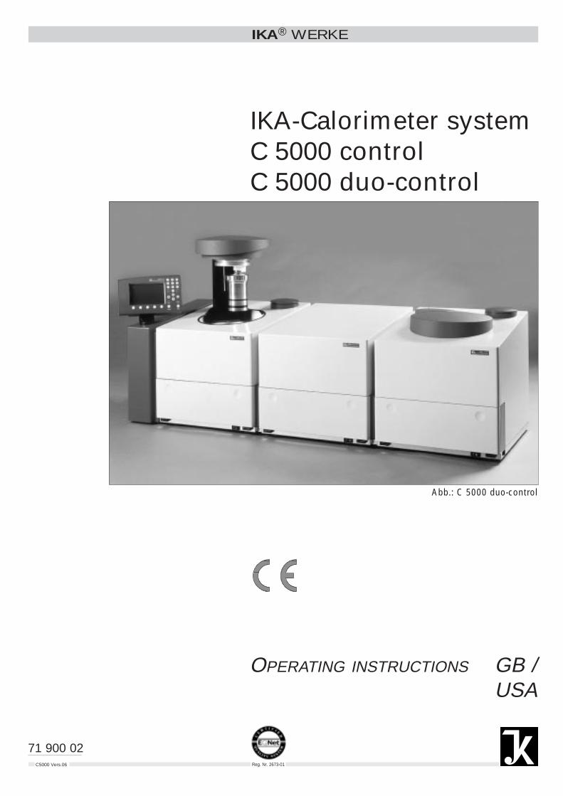
IKA ® WERKE C5000 Vers.06 IKA-Calorimeter system C 5000 control C 5000 duo-control OPERATING INSTRUCTIONS GB / USA 71 900 02 Abb.: C 5000 duo-control Reg. Nr. 2673-01
Transcript of IKA-Calorimeter system C 5000 control C 5000 duo-controlkemigf.ki.ku.dk/ovelse1a/GB_BA_C5000.pdf ·...
IKA® WERKE
C5000 Vers.06
IKA-Calorimeter systemC 5000 controlC 5000 duo-control
OPERATING INSTRUCTIONS GB /USA
71 900 02
Abb.: C 5000 duo-control
Reg. Nr. 2673-01
IKA-WERKE C5000 control / duo-control Ver. 06 01.99
CE – KONFORMITÄTSERKLÄRUNG DWir erklären in alleiniger Verantwortung, daß dieses Produkt den Bestimmungen derRichtlinien 89 / 336 EWG; 89 / 392 EWG und 73 / 23 EWG entspricht und mit Fol-genden Normen und normativen Dokumenten übereinstimmt:EN 61 010; EN 50 082; EN 55 014; EN 60 555.
CE – DECLARATION OF CONFIRMITY GBWe declare under our sole responsibility that this product corresponds to the regula-tions 89 / 336 EEC; 89 / 392 EEC and 73 / 23 EEC and conforms with the standardsor standardized documents:EN 61 010; EN 50 082; EN 55 014; EN 60 555.
DÉCLARATION DE CONFORMITÉ CE FNous déclarons sous notre responsabilité que ce produit est conforme aux régle-mentations 89 / 336 CEE; 89 / 392 CEE et 73 / 23 CEE et en conformité avec lesnormes ou documents normalisés suivants :EN 61 010; EN 50 082; EN 55 014; EN 60 555.
DECLARACION DE CONFORMIDAD DE CE EDeclaramos por nuestra responsabilidad propia que este produkto corresponde alas directrices 89 / 336 CEE; 89 / 392 CEE y 73 / 23 CEE y que cumple las normaso documentos normativos siguientes:EN 61 010; EN 50 082; EN 55 014; EN 60 555.
CE – DICHIARAZIONE DI CONFORMITÀ IDichiariamo, assumendone la piena responsabilità, che il prodotto è conforme alleseguenti direttive CCE 89 / 336 ; CCE 89 / 392 e CCE 73 / 23, in accordo ai se-guenti regolamenti e documenti:EN 61 010; EN 50 082; EN 55 014; EN 60 555.
IKA-LABORTECHNIK Janke & Kunkel GmbH & Co. KG
Staufen, February 18 1998
Wolfgang BuchmannDir. Techn. Documentation
Armin MattmüllerQuality Assurance
IKA-WERKE C5000 control / duo-control Ver. 06 01.99
Explanation of icons
This icon identifies information that is absolutely essential to ensure yourhealth and safety. Failure to observe this information may result in injury or mayadversely affect your health.
This icon identifies information that is significant for operating the equipment ina technically correct manner. Failure to observe this information may result indamage to the calorimeter system.
This icon identifies information that refers you to information that is important to op-erate calorimetric measurements properly and to work with the calorimeter system.Failure to observe this information may lead to imprecise results in measurements.
+
IKA-WERKE C5000 control / duo-control Ver. 06 01.99
Page I-1
Table of Contents
Page
1 For your safety......................................................................................................1-1
2 User notes.............................................................................................................2-1
2.1 Notes on using the operating instructions ..........................................................2-1
2.2 Guarantee............................................................................................................2-1
2.3 Warrantee and liability.........................................................................................2-1
3 Calorimetric measurements................................................................................3-1
3.1 Determining the gross calorific value ..................................................................3-1
3.2 Corrections ..........................................................................................................3-3
3.3 Complete combustion .........................................................................................3-4
3.4 Calibration............................................................................................................3-4
4 Features of the system........................................................................................4-1
5 Transportation, storage and setup location .....................................................5-1
5.1 Conditions for transportation and storage...........................................................5-1
5.2 Setup location ......................................................................................................5-1
6 Unpacking .............................................................................................................6-1
6.1 Included with delivery of the C 5000 control package 1 .....................................6-1
6.2 Included with delivery of the C 5000 control package 2 .....................................6-2
6.3 Included with delivery of the C 5000 duo-control package 3..............................6-3
7 Description of the system components ............................................................7-1
7.1 Controller with measurement cell........................................................................7-1
7.2 The C 5002 cooling system ................................................................................7-8
7.3 The C 5001 cooling system ..............................................................................7-10
7.4 The C 5004 cooling system ..............................................................................7-12
Table of Contents
IKA-WERKE C5000 control / duo-control Ver. 06 01.99
Page I-2
8 Setting up and placing in service .......................................................................8-1
8.1 Setting up package 1...........................................................................................8-2
8.2 Setting up package 2...........................................................................................8-6
8.3 Setting up package 3.........................................................................................8-10
8.4 Connecting peripheral devices..........................................................................8-13
8.5 Filling the system circuit....................................................................................8-14
8.6 Control and display elements............................................................................8-18
8.7 Turning on the system.......................................................................................8-21
8.8 Configuring the system .....................................................................................8-23
9 System calibration................................................................................................9-1
9.1 Charging the decomposition vessel with the calibration substance...................9-2
9.2 Calibration............................................................................................................9-6
10 Determining gross calorific values................................................................10-1
10.1 Notes on the sample .......................................................................................10-1
10.2 Acid correction.................................................................................................10-2
10.3 Procedure for determining gross calorific value .............................................10-2
10.4 Cleaning the decomposition vessel ................................................................10-5
10.5 Turning off the system.....................................................................................10-5
11 Evaluating experiments...................................................................................11-1
11.1 Post-processing experiments..........................................................................11-1
11.2 Calculating reference states / evaluation of experiments...............................11-4
12 Experiment simulation.....................................................................................12-1
13 Care and maintenance.....................................................................................13-1
13.1 Sieve insert......................................................................................................13-1
13.2 Changing the water .........................................................................................13-3
13.3 Replacing the inner cover / O2 filling piston ....................................................13-5
13.4 Replacing the O2 seal......................................................................................13-6
13.5 Decomposition vessels ...................................................................................13-6
14 Troubleshooting...............................................................................................14-1
14.1 Maintenance menu..........................................................................................14-1
14.2 Malfunction situations ......................................................................................14-2
14.3 Performing an adjustment (adiabatic mode)...................................................14-5
IKA-WERKE C5000 control / duo-control Ver. 06 01.99
Page I-3
15 Accessories and consumables ......................................................................15-1
16 Basic of calculations........................................................................................16-1
16.1 Calculations for calibration ..............................................................................16-1
16.2 Calculations during an experiment..................................................................16-1
16.3 “Standard without titration” mode....................................................................16-2
16.4 “Standard with titration” mode.........................................................................16-2
16.5 “Carbon: H2 input, without titration” mode.......................................................16-3
16.6 “Carbon: H2 input, with titration” mode............................................................16-5
16.7 “Carbon: volatile input, without titration” mode ...............................................16-7
16.8 “Carbon: volatile input, with titration” mode ....................................................16-8
16.9 Formula symbols ...........................................................................................16-11
17 Index of key words...........................................................................................17-1
IKA-WERKE C5000 control / duo-control Ver. 06 01.99
Page 1-1
1 For your safety
The C 5000 Calorimeter system has been developed and manufactured accordingto the most modern safety requirements. According to the stipulations, we mustdraw your attention to the following points:
The C 5000 calorimeter system may only be used to determine the gross calorificvalues of solid and liquid substances.
Many materials have a tendency to combust in an explosive manner (because ofperoxide formation, for example), which could result in the decomposition vesselbursting.
It is absolutely essential to use a special high-pressure decomposition vesselfor receiving fuel sample when performing research with fuel samples capableof exploding.The standard decomposition vessels C5010 and C5012 must not be used forthis purpose.
In addition, it is also possible that toxic combustion residues in the form of gasses,ashes or precipitates may form on the inner wall of the decomposition vessel.
When working with combustion samples, residues of combustion and auxiliary mate-rials, the safety precautions appropriate for each one must be observed. Hazardsmay be present, for example, in substances with any of the following characteristics
corrosiveeasily flammablecapable of explodingcontaminated with bacteriatoxicradioactive
When using crucibles made of stainless steel, you should check their conditioncarefully after the experiment. After a maximum of 25 combustions, the cruciblesmay no longer be used for reasons of safety.
The unit may only be operated by a professional or a person who has received in-struction. Among other qualifications, the user must be familiar with combustion pro-cesses and products of combustion that arise during the process.
The decomposition vessel corresponds to the requirements of the German regulationDK 621.642-986 on pressure containers (Group II). A manufacturer’s certificate isincluded with the accompanying papers. This should be kept, since it must be pre-sented upon the request of safety authorities.
According to the regulation on pressure containers, the operator is responsi-ble for the safety of the decomposition vessel.
Pressure tests and service work on the decomposition vessel may only be per-formed by authorized personnel.
Explosivematerials
Applicationpurpose
Combustionsamples, resi-dues and aux-iliary materials
Qualificationsof the user
Decompositionvessel
1 For your safety
IKA-WERKE C5000 control / duo-control Ver. 06 01.99
Page 1-2
We urgently recommend that you regularly send the decomposition vessel into our factory to be checked or repaired (see maintenance contract).
For detailed references, please read the Operating Instructions for the decomposi-tion vessels C5010/C5012.
German regulation DK 621.642-986 on pressure containers (excerpt):
§8 Categorization into test groupsPressure containers are categorized according to the permissible operating pres-sure p in bars, the capacity of the pressure area I in liters and the pressure contentproduct p•I. If there are several pressure areas that are separated from each other,the product for each pressure area is determined separately. The following catego-ries are distinguished:
Group II:Pressure containers with a permissible operating pressure p of more than 0.1 bar,but not more than 1 bar, and pressure containers with a permissible operating pres-sure p of more than 1 bar, for which the pressure content product p•I is not morethan 200.
§ 10 Recurring tests(2) A pressure container of Group I, II, III, IV and VI must be subject to recurringtests by professionally competent personnel. The timing of the tests will be deter-mined by the operator according to experience with the work procedure and the typeof coating.
§ 13 Operating pressure containers(1) Anyone who operates a pressure container must maintain the same in properoperating condition, must operate it properly, must monitor it, must perform neces-sary maintenance and repair work without delay, and must take necessary safetymeasures corresponding to circumstances.
(3) A pressure container must not be operated if it has any defect that endangersemployees or a third party.
The calorimeter system may only be opened by a maintenance or customer servicelocation.We recommend you refer to our customer service department for your serviceneeds.
Parts that conductelectricity
+
Regulation onpressurecontainers
IKA-WERKE C5000 control / duo-control Ver. 06 01.99
Page 2-1
2 User notes
2.1 Notes on using the operating instructions
In this section you will learn how to work through these Operating Instructions in themost effective manner to be able to work safely with the calorimeter system.
The instructions in Section 1 “For your Safety” must be followed.
You should work through sections 1 through 9 in order, one after the other. In Sec-tion 3 “Calorimetric measurements,” you will find helpful information about deter-mining gross calorific values with calorimeters. Section 4 “Features of the system”provides you with information about standards to which the system conforms,measurement ranges of the system and the reference states into which the grosscalorific value can be converted. Section 5 “Transportation, storage and setup loca-tion” is of relevance for the reliability of the system and for ensuring a high degree ofreliability in measurements.In addition to the description of system components, Section 7 contains technicaldata on individual components.The calorimeter system is ready for a measurement after you have performed theprocedures in Section 8 “Setting up and placing in service” and Section 9 “Systemcalibration”. The following determinations of gross calorific values should be per-formed according to Section 10 “Determining gross calorific values” and Section 11“Evaluating experiments”.
2.2 Guarantee
You have purchased an Original IKA-WERKE device, which conforms to the higheststandards of technology and quality. The guarantee is for 12 months, according tothe IKA guarantee conditions. If you need to use the guarantee, please refer to theappropriate dealership or supplier. You can also send the unit directly to the IKAfactory, including with it the invoice from the supplier and stating the reasons forreturning it, and telling us who the contact person is. Shipping costs are paid by thesender.
2.3 Warrantee and liability
Please read through these Operating Instructions attentively. IKA WERKE considersitself responsible for the safety, reliability and performance of the device only:
• If the unit has been used in accordance with the operating instructions
• If only persons authorized by the manufacturer perform maintenance on or make repairs to the unit, and
WorkingthroughSections 1 … 9
Performingexperiments
2 User notes
IKA-WEKE C5000 control / duo-control Ver. 06 01.99
Page 2-2
• If only original parts and original accessories are used for repairs.
We also direct your attention to the appropriate safety requirements and accidentprevention specifications.IKA WERKE is not responsible for damages or costs resulting from accident, misuseof the unit or unauthorized modifications, repairs or innovations.
IKA-WERKE C5000 control / duo-control Ver. 06 01.99
Page 3-1
3 Calorimetric measurements
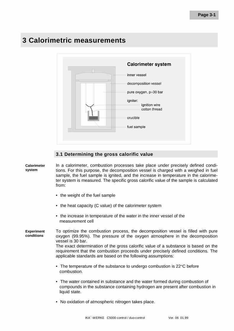
3.1 Determining the gross calorific value In a calorimeter, combustion processes take place under precisely defined condi-tions. For this purpose, the decomposition vessel is charged with a weighed in fuelsample, the fuel sample is ignited, and the increase in temperature in the calorime-ter system is measured. The specific gross calorific value of the sample is calculatedfrom:
• the weight of the fuel sample
• the heat capacity (C value) of the calorimeter system
• the increase in temperature of the water in the inner vessel of the measurement cell To optimize the combustion process, the decomposition vessel is filled with pureoxygen (99.95%). The pressure of the oxygen atmosphere in the decompositionvessel is 30 bar. The exact determination of the gross calorific value of a substance is based on therequirement that the combustion proceeds under precisely defined conditions. Theapplicable standards are based on the following assumptions:
• The temperature of the substance to undergo combustion is 22°C before combustion.
• The water contained in substance and the water formed during combustion of compounds in the substance containing hydrogen are present after combustion in liquid state.
• No oxidation of atmospheric nitrogen takes place.
Calorimetersystem
Experimentconditions
3 Calorimetric measurements
IKA-WERKE C5000 control / duo-control Ver. 06 01.99
Page 3-2
• The gaseous products of combustion consist of oxygen, nitrogen, carbon dioxide and sulfur dioxide.
• Solid ash is formed.
Often, however, the products of combustion assumed by the standards are not theonly ones that are formed. In such cases, analyses must be performed on the fuelsample and the combustion products that yield data for a correction calculation. Thestandard gross calorific value is then determined from the measured gross calorificvalue and the analysis data.
The Ho gross calorific value is formed from the quotient of the quantity of heat liber-ated during complete combustion of a solid or liquid combustible substance and theweight of the fuel sample. In this calculation, the water formed before the combus-tion of compounds of the combustible substance must be present in a liquid stateafter the combustion. Reference temperature 22°C
The net calorific value Hu is equal to the gross calorific value reduced by the energyof condensation of the water that was contained in the combustible substance that isformed by combustion. The net calorific value is the technically more importantquantity, since only the net calorific value can be evaluated in terms of energy in allimportant, technical applications.
On the calculation formulas for gross and net calorific value, see Section 16 “Basicof calculations”
Ho grosscalorific value
Hu net calorificvalue
IKA-WERKE C5000 control / duo-control Ver. 06 01.99
Page 3-3
3.2 Corrections
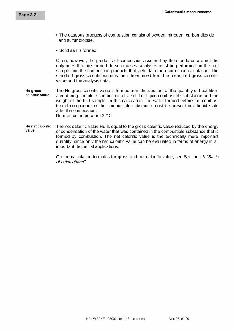
During a combustion experiment, as conditioned by the system, heat is not gener-ated only by combustion of the sample; in addition heat also arises through extrane-ous energy:
The heat of combustion of the cotton thread that ignites the sample and the heat ofelectrical ignition would distort the measurement. This effect is taken into account inthe calculation with a correction value.
Substances with low inflammability and substances that do not readily undergocombustion are burned together with a combustion aid. The combustion aid is firstweighed and is then placed in the crucible with the sample. From the weight of thecombustion aid and a specific gross calorific value that is of course already known, itis possible to determine the amount of heat that is introduced by the combustion aid.The result of the experiment must then be corrected by that quantity of heat.
The C14 combustible crucible can be used instead of a more traditional crucible.The combustible crucible is burned completely with no residue. When a combustiblecrucible is used, no additional cotton thread is required. The crucible is contacteddirectly by the fixed ignition wire of the decomposition vessel and is ignited. The purity of the material of the combustible crucible prevents chemical contamina-tion of the sample material (no blank values). Decomposition vessel in which the combustible crucible is used must be retrofittedwith an additional part (attachment C5010.4, see accessories). The sample isweighed in into the combustible crucible normally. In most cases, no additionalcombustion aid is required, because the combustible crucible itself serves as acombustion aid.
The C14 combustible crucible cannot be used in combination with the samplerack.
Almost all substances to be analyzed contain sulfur and nitrogen. Under theconditions that prevail in calorimetric measurements, sulfur and nitrogen burn and
Igniter
Combustion aid
combustiblecrucible C14
+Acid correction
Heat of combustion andextraneous energy:
The extraneous energycan vary considerably
in relation to the heat ofcombustion of the fuel
sample.
3 Calorimetric measurements
IKA-WERKE C5000 control / duo-control Ver. 06 01.99
Page 3-4
are reduced to SO2, SO3 and NOx. In combination with the water from combustionand moisture, sulfuric acid and nitric acid are produced in addition to heat of solu-tion. In order to obtain the standard gross calorific value, the gross calorific value iscorrected by the effect of the heat of solution. In order to obtain a defined final state and to measure all acids quantitatively, 5 ml ofdistilled water is placed in the decomposition vessel before the experiment. Thegasses liberated during combustion form acids with the distilled water. After thecombustion, the decomposition vessel is rinsed thoroughly with distilled water tocollect the precipitate that has been deposited on the inner wall of the vessel aswell. The water that was placed in the decomposition vessel is combined with therinse water to be titrated for acid content.
3.3 Complete combustion
To determine the gross calorific value correctly, it is of fundamental significance forthe sample to be burned completely. After the experiment, the crucible and all solidresidues must be examined for signs of incomplete combustion.
Normally, solid combustion substances can be burned directly in powder form. Sub-stances that burn rapidly, i.e. substances for which the combustion has the nature ofan explosion (for example benzoic acid) must not be burned in loose form. Thesesubstances tend to spark, and complete combustion could therefore no longer beguaranteed. In addition, the decomposition vessel could be damaged. Such sub-stances must be pressed into tablets before combustion (see Accessories).
Substances with low inflammability (substances with a high mineral content, low-calorific materials) often can be burned only with the aid of combustion capsules orcombustion bags (see Accessories). It is also possible to use liquid combustion aidssuch as paraffin oil or hydrocarbon oil.
Most liquid substances can be weighed directly into the crucible. Highly volatile sub-stances are placed in combustion capsules (gelatin capsules ore acetobutyrate cap-sules, see Accessories) and are burned together with the capsules. The igniters (cotton thread) must be completely burned as well. If unburned remain-ders of the igniter are left over, the experiment must be repeated or a correctionmust be introduced into the result through the extraneous energy.
Substances with high halogen content can cause corrosion to appear on the de-composition vessel. Decomposition vessel C5012 should be used for these pur-poses.
3.4 Calibration
To ensure exact reproducible measurement results, the calorimeter system is cali-brated after it is first placed in service, after maintenance work, after parts are re-placed and at specific time intervals. During calibration, the heat capacity of thecalorimeter system is re-determined.
Regular calibration is absolutely essential to maintain accuracy of measure-ment. Furthermore, the system must be calibrated in the operating mode thatwill be used for the experiment (adiabatic, isoperibolic or dynamic).
Solidsubstances
Substanceswith lowinflammability
Liquid andhighly volatilesubstances
+
Halogens
IKA-WERKE C5000 control / duo-control Ver. 06 01.99
Page 3-5
For this purpose, a specific quantity of a reference substance is burned in the de-composition vessel under the conditions of the experiment. Since the gross calorificvalue of the reference substance is known, it is possible to use the increase in tem-perature of the calorimeter system when the reference substance is burned to cal-culate the heat capacity.
The reference substance for calorimetry that is recognized at an international level isbenzoic acid obtained from the National Bureau of Standards (NBS-Standard Sam-ple 39), with a guaranteed gross calorific value.
If a calorimeter is being operated with more than one decomposition vessel,the heat capacity of the system must be determined for each decompositionvessel. For more detailed information on calibration, please refer to the appropriate stan-dards as they are listed in Section 4 Features of the system.
+
IKA-WERKE C5000 control / duo-control Ver. 06 01.99
Page 4-1
4 Features of the system
The C 5000 control and C 5000 duo-control calorimeter systems are used for rou-tine determinations of the gross calorific value of solid and liquid substances. Thetwo systems conform to all gross calorific value standards in accepted use, and arethus recognized worldwide. The extensive selection of accessories and the modulardesign of the systems ensure customized adaptation to laboratory tasks. During theprocess of an experiment, the software takes care of communication with externaldevices (for example analytical scale, sample rack) as well as management of sam-ples, decomposition vessels and experiment results that eliminates mix-ups. The two systems are distinguished by the following features:
l A fully automated measurement procedure eliminates the need fortime-consuming routine tasks.
l Integrated oxygen filling and degassing.
l Measurement of gross and net calorific value according to DIN 51900,BS 1016 Part 5 1977, ASTM D3286-91, ASTM D240-87, ASTM E711-87,ISO 1928-1976, ASTM D1989-91 and BSI.
l Measurement range: max. 40,000 JThis corresponds to an increase in temperature within the inner vessel of 4K.
l Work can be performed based on the adiabatic, isoperibolic or dynamicprinciple.
l Calculation of the gross calorific value based on the following correctionmethods:
- standard without titration- standard with titration- carbon: hydrogen without titration- carbon: hydrogen with titration- carbon: volatile component parts without titration- carbon: volatile component parts with titration- acid correction based on ASTM 240- acid correction based on ASTM 1989
IKA-WERKE C5000 control / duo-control Ver. 06 01.98
1Page 5-1
5 Transportation, storage and setup location
5.1 Conditions for transportation and storage
The system must be protected from mechanical bumps, vibrations, accumulations ofdust and corrosive ambient air during transportation and storage. It is also importantto observe that the relative humidity not exceed 80%. If the system is shipped backto the factory, only the original packaging may be used.
5.2 Setup location
To ensure high precision in measurements, a constant ambient temperature is re-quired for the system. The following conditions must therefore be observed at thesetup location:
l No exposure to direct sunlight.
l No drafts (for example next to windows, doors, air conditioners).
l A sufficient distance from heater blocks and other sources of heat.
l Adequate circulation of air must be ensured to divert the system’s own heat.
l The minimum distance between the wall and the rear side of the unit mustnot be less than 25 cm.
l The system must not have laboratory material such as shelves, cablesleeves, ring leads, etc, built over it.
l The room temperature must fall within the range of 20 - 25°C.
l The system must be set up on a horizontal surface.
To operate the system, the setup location must provide a power supply that con-forms to the specifications on the rating plates of the system components, as well asa supply of oxygen (99.95% pure oxygen, quality 3.5, pressure 30 bar) with the ap-propriate pressure indicator.
++
IKA-WERKE C5000 control / duo-control Ver. 06 01.99
Page 6-1
6 Unpacking
Please unpack the unit carefully and make note of any damages. It is important thatany damage that occurred during shipping be noted at once while unpacking. Ifdamage has occurred, you should take stock of this damage immediately (notingwhether by mail, rail or express delivery, etc.).
The following sections describe the entire range of components included with deliv-ery, including the various system variants.
6.1 Included with delivery of the C 5000 control package 1
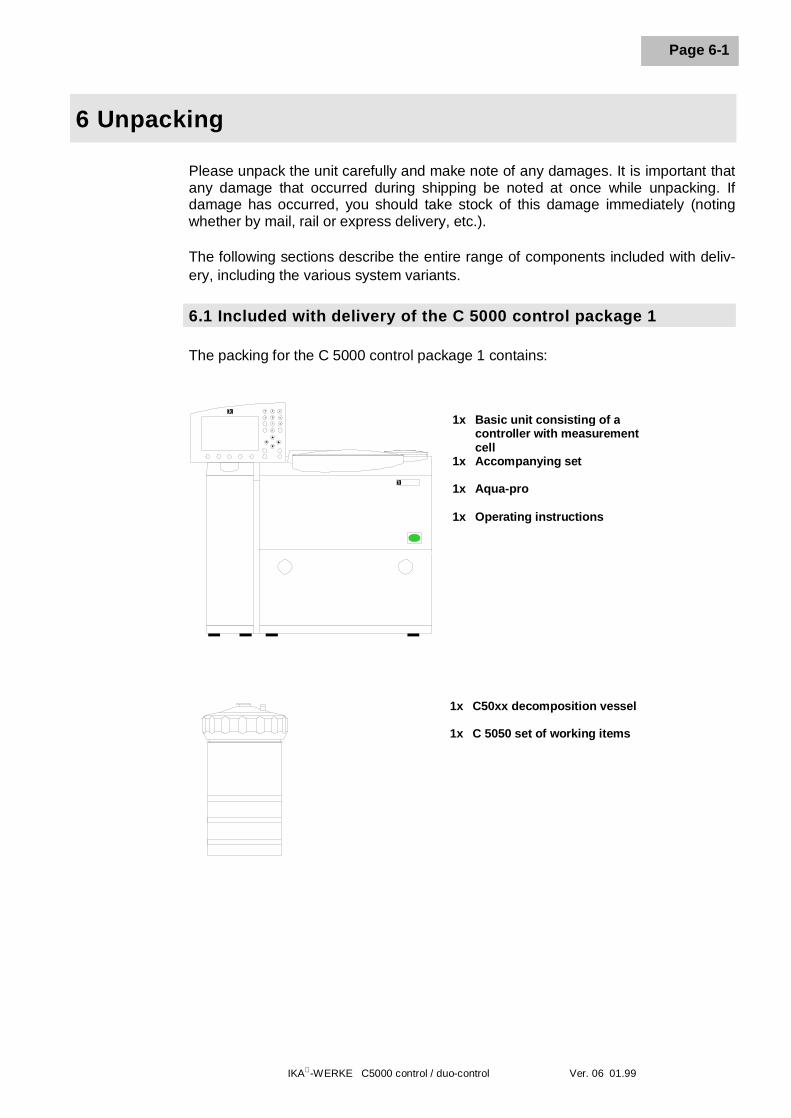
The packing for the C 5000 control package 1 contains:
1x Basic unit consisting of acontroller with measurementcell
1x Accompanying set 1x Aqua-pro 1x Operating instructions
1x C50xx decomposition vessel 1x C 5050 set of working items
6 Unpacking
IKA-WERKE C5000 control / duo-control Ver. 06 01.99
Page 6-2
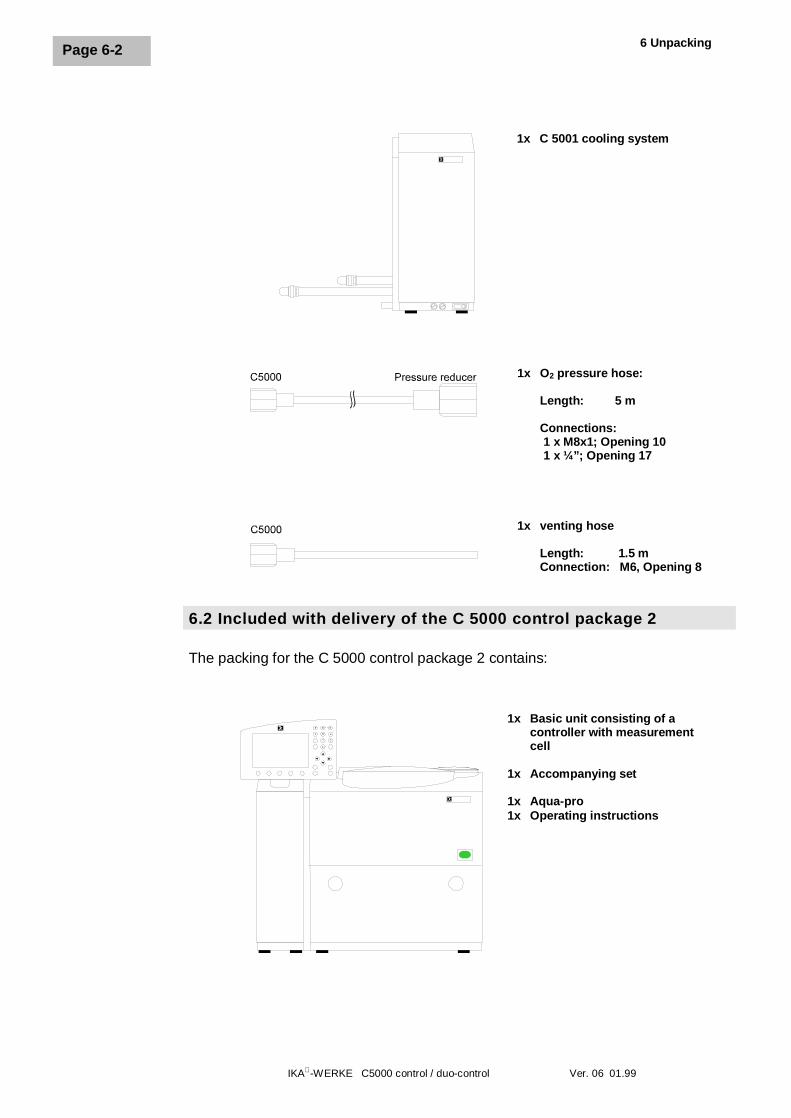
6.2 Included with delivery of the C 5000 control package 2
The packing for the C 5000 control package 2 contains:
1x C 5001 cooling system
1x O2 pressure hose:
Length: 5 m Connections: 1 x M8x1; Opening 10 1 x ¼”; Opening 17
1x venting hose
Length: 1.5 mConnection: M6, Opening 8
1x Basic unit consisting of acontroller with measurementcell
1x Accompanying set 1x Aqua-pro 1x Operating instructions
IKA-WERKE C5000 control / duo-control Ver. 06 01.99
Page 6-3
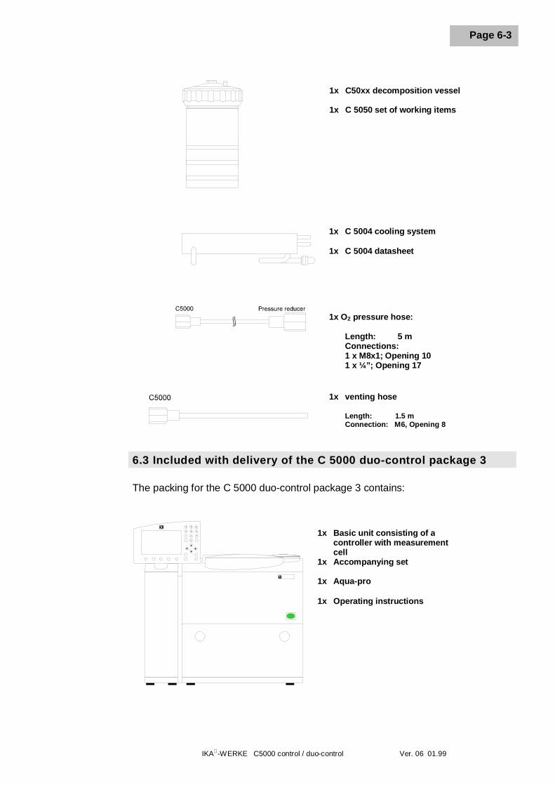
6.3 Included with delivery of the C 5000 duo-control package 3
The packing for the C 5000 duo-control package 3 contains:
1x C50xx decomposition vessel 1x C 5050 set of working items
1x C 5004 cooling system 1x C 5004 datasheet
1x O2 pressure hose:
Length: 5 m Connections: 1 x M8x1; Opening 10 1 x ¼”; Opening 17
1x venting hose
Length: 1.5 mConnection: M6, Opening 8
1x Basic unit consisting of acontroller with measurementcell
1x Accompanying set 1x Aqua-pro 1x Operating instructions
6 Unpacking
IKA-WERKE C5000 control / duo-control Ver. 06 01.99
Page 6-4
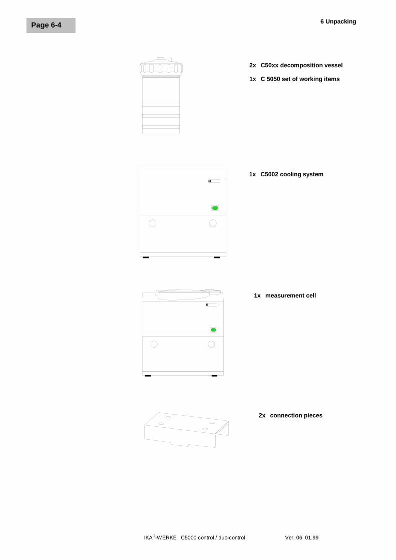
2x C50xx decomposition vessel 1x C 5050 set of working items
1x C5002 cooling system
1x measurement cell
2x connection pieces
IKA-WERKE C5000 control / duo-control Ver. 06 01.99
Page 6-5
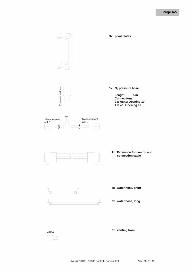
3x pivot plates
1x O2 pressure hose: Length: 5 m Connections: 2 x M8x1; Opening 10 1 x ¼”; Opening 17
1x Extension for control andconnection cable
2x water hose, short
2x water hose, long
2x venting hose
IKA-WERKE C5000 control / duo-control Ver. 06 01.99
Page 7-1
7 Description of the system components
7.1 Controller with measurement cell
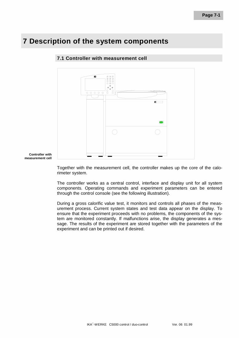
Together with the measurement cell, the controller makes up the core of the calo-rimeter system.
The controller works as a central control, interface and display unit for all systemcomponents. Operating commands and experiment parameters can be enteredthrough the control console (see the following illustration).
During a gross calorific value test, it monitors and controls all phases of the meas-urement process. Current system states and test data appear on the display. Toensure that the experiment proceeds with no problems, the components of the sys-tem are monitored constantly. If malfunctions arise, the display generates a mes-sage. The results of the experiment are stored together with the parameters of theexperiment and can be printed out if desired.
Controller withmeasurement cell
7 Description of the system components
IKA-WERKE C5000 control / duo-control Ver. 06 01.99
Page 7-2
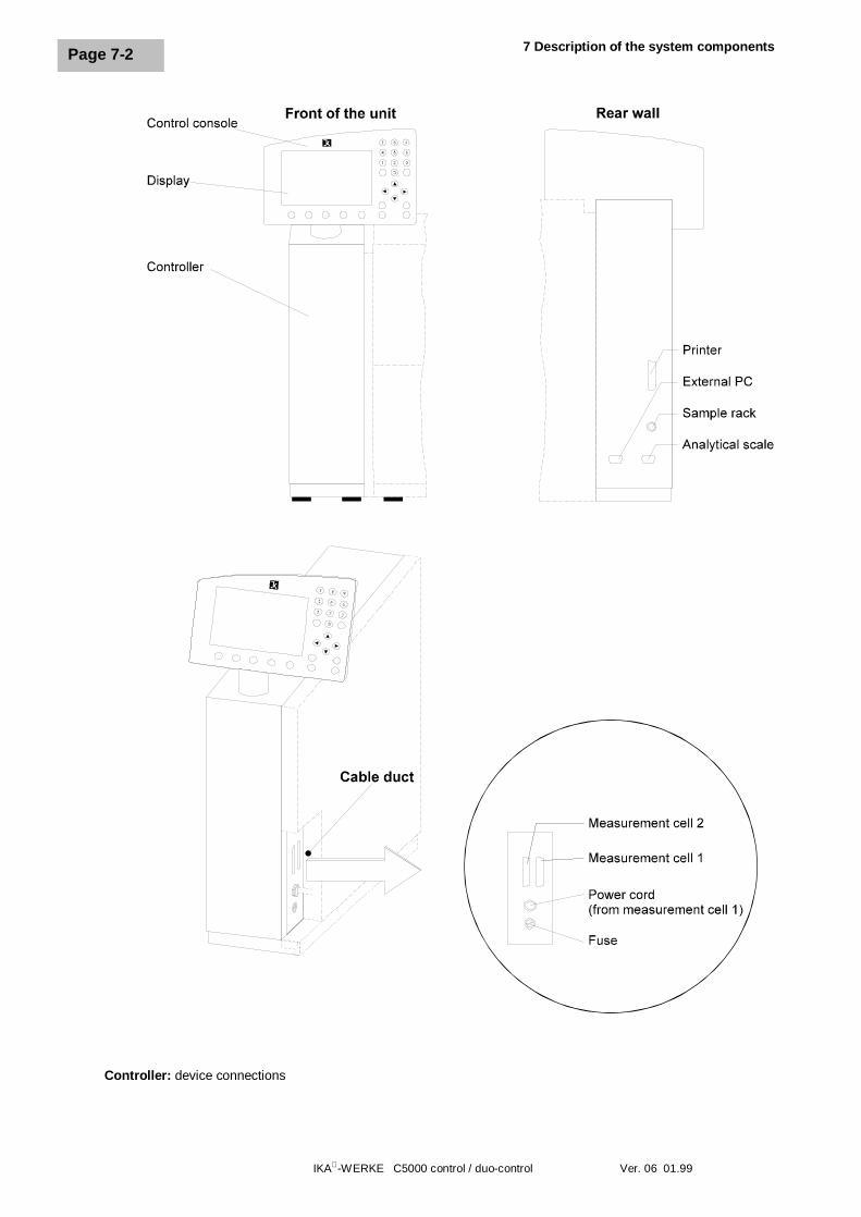
Controller: device connections
IKA-WERKE C5000 control / duo-control Ver. 06 01.99
Page 7-3
The individual tasks performed by the controller are as follow:
l Dialog with the user through the control console
l Store experiment data and experiment protocols ordered by experiment,experiment documentation
l Perform experiments automatically, control and monitoring ofmeasurement cell(s)
l Communication with the peripheral devices:Printer, analytical scale, sample rack, external PC
Technical data for the controller
Operating power Electrical power is supplied through measurementcell to conform to rating plate.
Power consumption C 5000 control: max 1300 Watts(controller with one measurement cell)C 5000 duo-control: max. 2500 Watts(controller with two measurement cells)
Device fuses 1 x 3.15 A, T; 230V / 1 x 6.25 A, T; 100V, 115VDimensions (WxDxH) 560 x 380 x 397 mm
(Controller with measurement cell, w/o display)Weight 41 kg (controller with measurement cell)
Ambient temperature 15 … 30°CPermissible humidity 80%Enclosure rating IP 21
Display 320 x 200 pixels, with illuminated background
Contamination level II
Over-voltage category 2
Enclosure rating 1 (protective ground)
7 Description of the system components
IKA-WERKE C5000 control / duo-control Ver. 06 01.99
Page 7-4
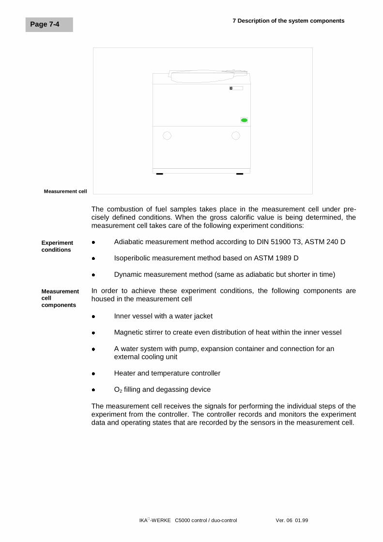
The combustion of fuel samples takes place in the measurement cell under pre-cisely defined conditions. When the gross calorific value is being determined, themeasurement cell takes care of the following experiment conditions:
l Adiabatic measurement method according to DIN 51900 T3, ASTM 240 D
l Isoperibolic measurement method based on ASTM 1989 D
l Dynamic measurement method (same as adiabatic but shorter in time)
In order to achieve these experiment conditions, the following components arehoused in the measurement cell
l Inner vessel with a water jacket
l Magnetic stirrer to create even distribution of heat within the inner vessel
l A water system with pump, expansion container and connection for anexternal cooling unit
l Heater and temperature controller
l O2 filling and degassing device
The measurement cell receives the signals for performing the individual steps of theexperiment from the controller. The controller records and monitors the experimentdata and operating states that are recorded by the sensors in the measurement cell.
Measurement cell
Experimentconditions
Measurementcellcomponents
IKA-WERKE C5000 control / duo-control Ver. 06 01.99
Page 7-5
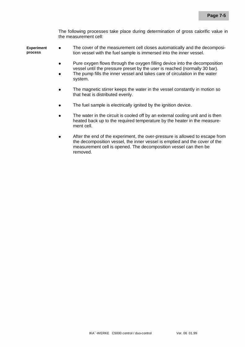
The following processes take place during determination of gross calorific value inthe measurement cell:
l The cover of the measurement cell closes automatically and the decomposi-tion vessel with the fuel sample is immersed into the inner vessel.
l Pure oxygen flows through the oxygen filling device into the decompositionvessel until the pressure preset by the user is reached (normally 30 bar).
l The pump fills the inner vessel and takes care of circulation in the watersystem.
l The magnetic stirrer keeps the water in the vessel constantly in motion sothat heat is distributed evenly.
l The fuel sample is electrically ignited by the ignition device.
l The water in the circuit is cooled off by an external cooling unit and is thenheated back up to the required temperature by the heater in the measure-ment cell.
l After the end of the experiment, the over-pressure is allowed to escape fromthe decomposition vessel, the inner vessel is emptied and the cover of themeasurement cell is opened. The decomposition vessel can then beremoved.
Experimentprocess
7 Description of the system components
IKA-WERKE C5000 control / duo-control Ver. 06 01.99
Page 7-6
IKA-WERKE C5000 control / duo-control Ver. 06 01.99
Page 7-7
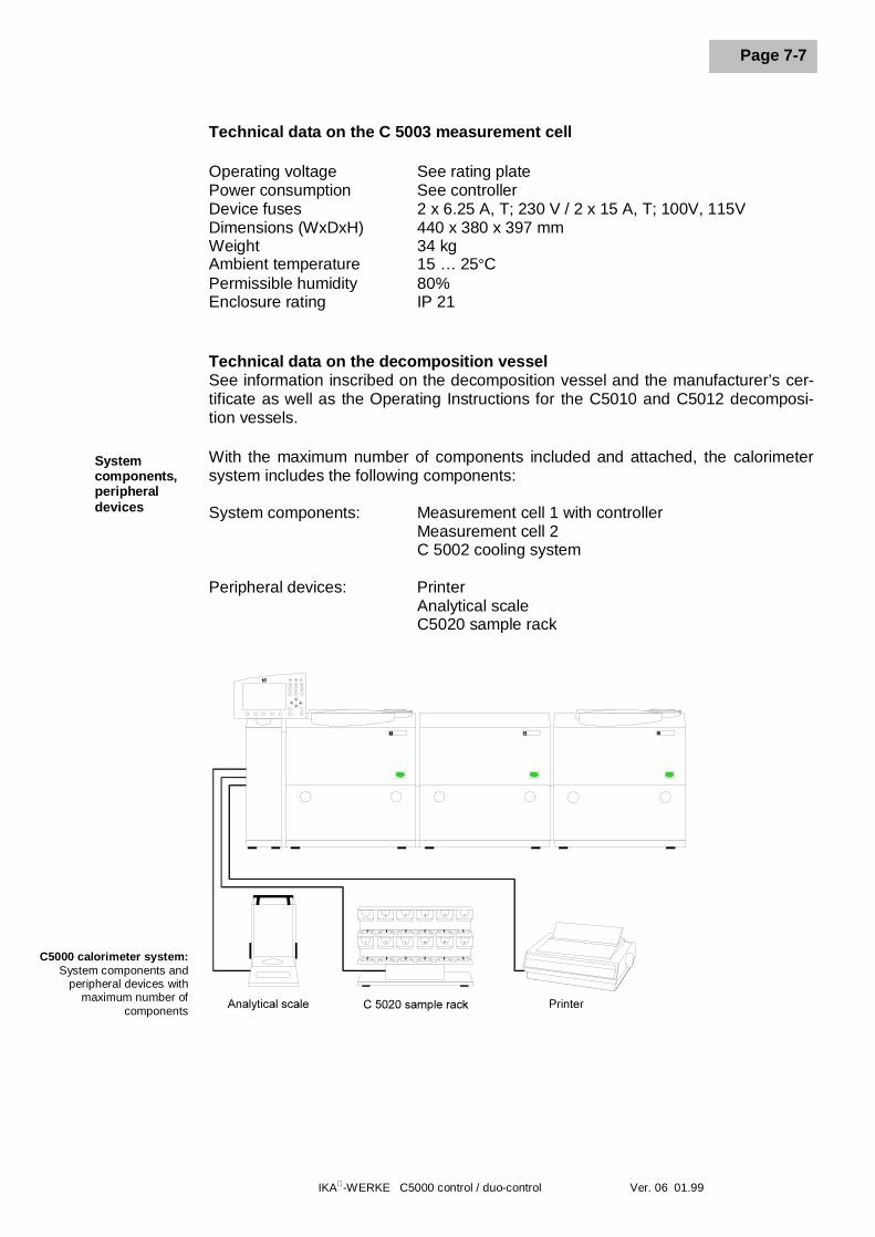
Technical data on the C 5003 measurement cell
Operating voltage See rating platePower consumption See controllerDevice fuses 2 x 6.25 A, T; 230 V / 2 x 15 A, T; 100V, 115VDimensions (WxDxH) 440 x 380 x 397 mmWeight 34 kgAmbient temperature 15 … 25°CPermissible humidity 80%Enclosure rating IP 21
Technical data on the decomposition vesselSee information inscribed on the decomposition vessel and the manufacturer’s cer-tificate as well as the Operating Instructions for the C5010 and C5012 decomposi-tion vessels.
With the maximum number of components included and attached, the calorimetersystem includes the following components:
System components: Measurement cell 1 with controllerMeasurement cell 2C 5002 cooling system
Peripheral devices: PrinterAnalytical scaleC5020 sample rack
Systemcomponents,peripheraldevices
C5000 calorimeter system:System components and
peripheral devices withmaximum number of
components
7 Description of the system components
IKA-WERKE C5000 control / duo-control Ver. 06 01.99
Page 7-8
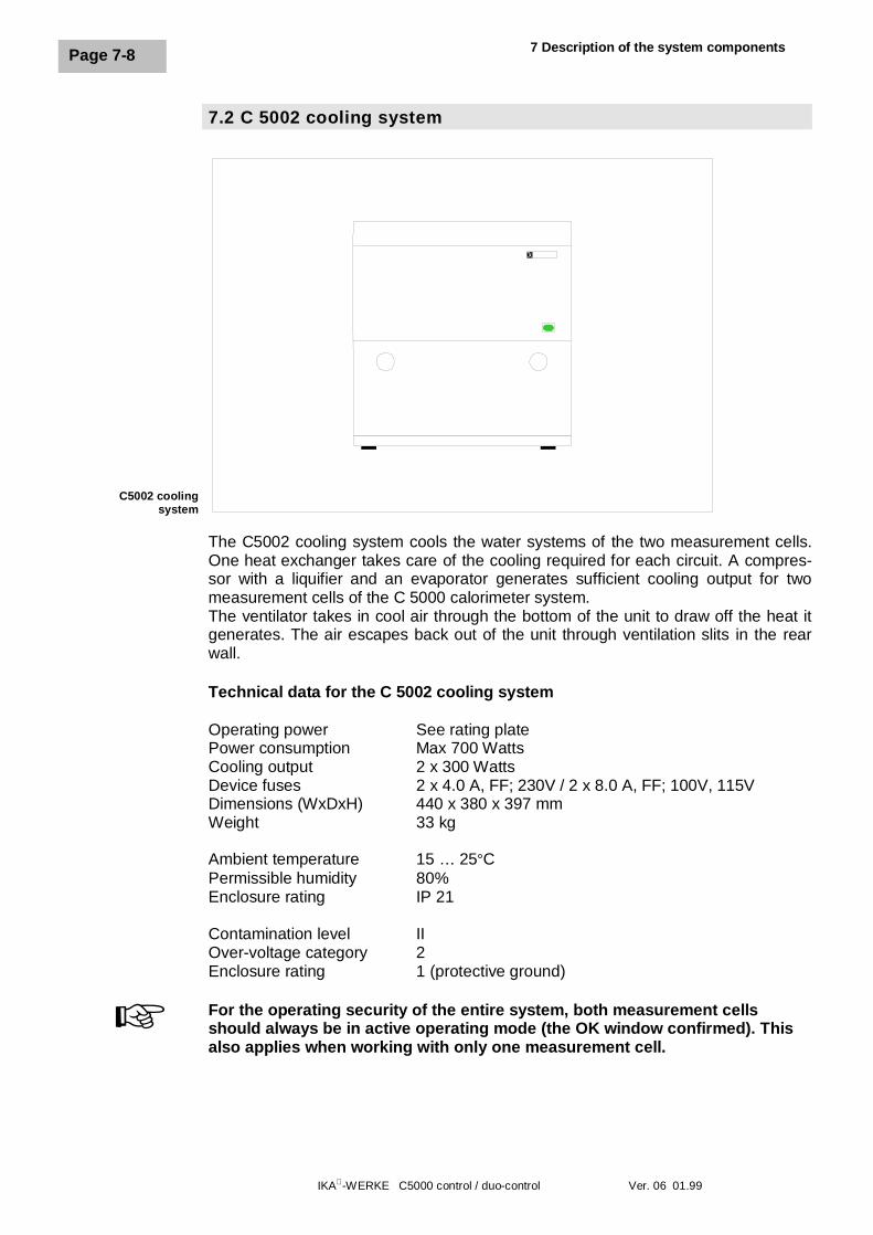
7.2 C 5002 cooling system
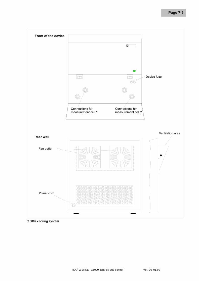
The C5002 cooling system cools the water systems of the two measurement cells.One heat exchanger takes care of the cooling required for each circuit. A compres-sor with a liquifier and an evaporator generates sufficient cooling output for twomeasurement cells of the C 5000 calorimeter system.The ventilator takes in cool air through the bottom of the unit to draw off the heat itgenerates. The air escapes back out of the unit through ventilation slits in the rearwall.
Technical data for the C 5002 cooling system
Operating power See rating platePower consumption Max 700 WattsCooling output 2 x 300 WattsDevice fuses 2 x 4.0 A, FF; 230V / 2 x 8.0 A, FF; 100V, 115VDimensions (WxDxH) 440 x 380 x 397 mmWeight 33 kg
Ambient temperature 15 … 25°CPermissible humidity 80%Enclosure rating IP 21
Contamination level IIOver-voltage category 2Enclosure rating 1 (protective ground)
For the operating security of the entire system, both measurement cellsshould always be in active operating mode (the OK window confirmed). Thisalso applies when working with only one measurement cell.
C5002 coolingsystem
+
IKA-WERKE C5000 control / duo-control Ver. 06 01.99
Page 7-9
C 5002 cooling system
7 Description of the system components
IKA-WERKE C5000 control / duo-control Ver. 06 01.99
Page 7-10
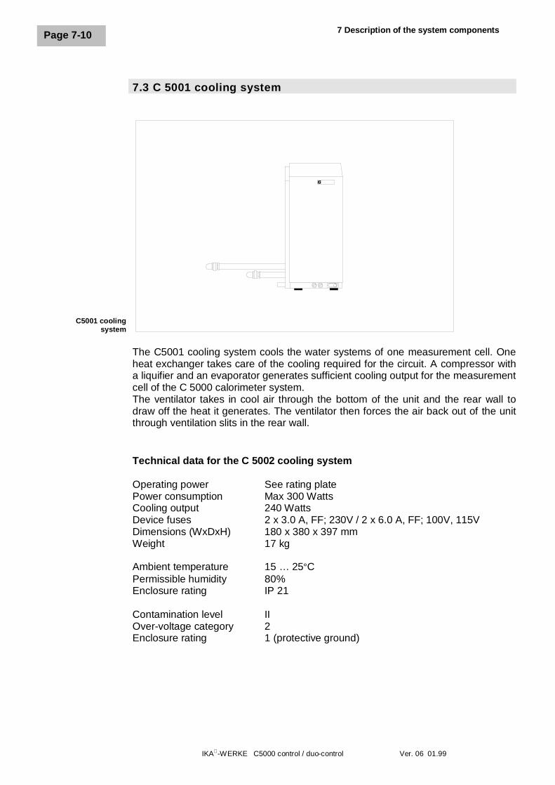
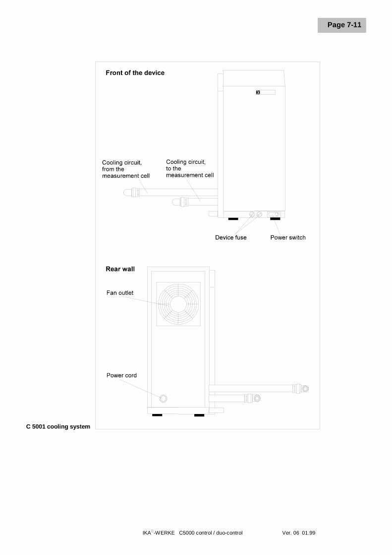
7.3 C 5001 cooling system
The C5001 cooling system cools the water systems of one measurement cell. Oneheat exchanger takes care of the cooling required for the circuit. A compressor witha liquifier and an evaporator generates sufficient cooling output for the measurementcell of the C 5000 calorimeter system.The ventilator takes in cool air through the bottom of the unit and the rear wall todraw off the heat it generates. The ventilator then forces the air back out of the unitthrough ventilation slits in the rear wall.
Technical data for the C 5002 cooling system
Operating power See rating platePower consumption Max 300 WattsCooling output 240 WattsDevice fuses 2 x 3.0 A, FF; 230V / 2 x 6.0 A, FF; 100V, 115VDimensions (WxDxH) 180 x 380 x 397 mmWeight 17 kg
Ambient temperature 15 … 25°CPermissible humidity 80%Enclosure rating IP 21
Contamination level IIOver-voltage category 2Enclosure rating 1 (protective ground)
C5001 coolingsystem
IKA-WERKE C5000 control / duo-control Ver. 06 01.99
Page 7-11
C 5001 cooling system
7 Description of the system components
IKA-WERKE C5000 control / duo-control Ver. 06 01.99
Page 7-12
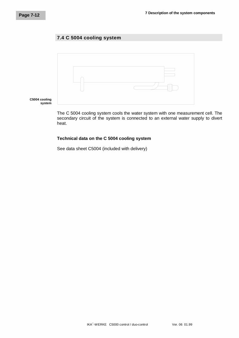
7.4 C 5004 cooling system
The C 5004 cooling system cools the water system with one measurement cell. Thesecondary circuit of the system is connected to an external water supply to divertheat.
Technical data on the C 5004 cooling system
See data sheet C5004 (included with delivery)
C5004 coolingsystem
IKA-WERKE C5000 control / duo-control Ver. 06 01.99
Page 8-1
8 Setting up and placing in service
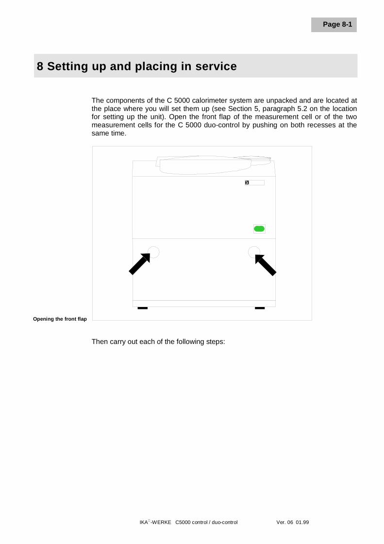
The components of the C 5000 calorimeter system are unpacked and are located atthe place where you will set them up (see Section 5, paragraph 5.2 on the locationfor setting up the unit). Open the front flap of the measurement cell or of the twomeasurement cells for the C 5000 duo-control by pushing on both recesses at thesame time.
Then carry out each of the following steps:
Opening the front flap
8 Setting up and placing in service
IKA-WERKE C5000 control / duo-control Ver. 06 01.99
Page 8-2
8.1 Setting up package 1
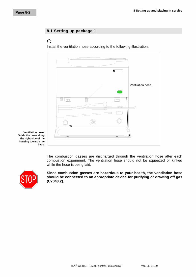
�Install the ventilation hose according to the following illustration:
The combustion gasses are discharged through the ventilation hose after eachcombustion experiment. The ventilation hose should not be squeezed or kinkedwhile the hose is being laid.
Since combustion gasses are hazardous to your health, the ventilation hoseshould be connected to an appropriate device for purifying or drawing off gas(C7048.2).
Ventilation hose:Guide the hose along
the right side of thehousing towards the
back.
IKA-WERKE C5000 control / duo-control Ver. 06 01.99
Page 8-3
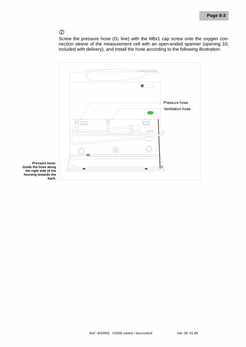
ôScrew the pressure hose (O2 line) with the M8x1 cap screw onto the oxygen con-nection sleeve of the measurement cell with an open-ended spanner (opening 10,included with delivery), and install the hose according to the following illustration:
Pressure hose:Guide the hose along
the right side of thehousing towards the
back.
8 Setting up and placing in service
IKA-WERKE C5000 control / duo-control Ver. 06 01.99
Page 8-4
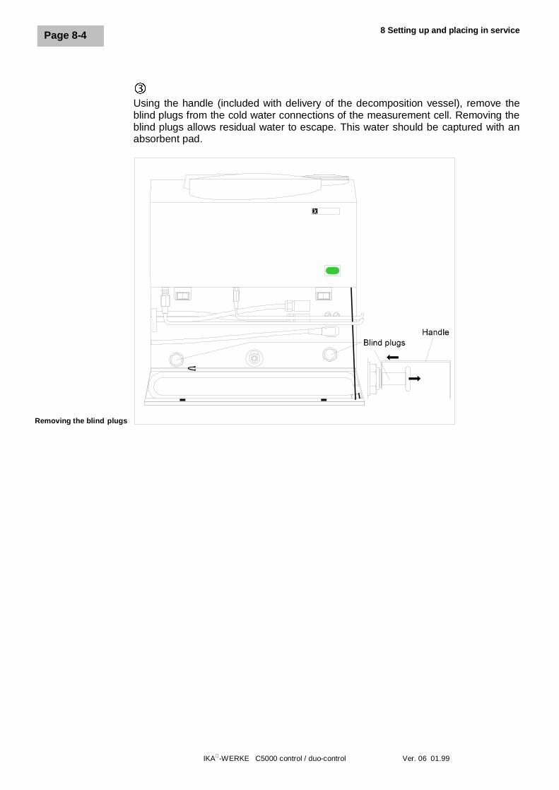
íUsing the handle (included with delivery of the decomposition vessel), remove theblind plugs from the cold water connections of the measurement cell. Removing theblind plugs allows residual water to escape. This water should be captured with anabsorbent pad.
Removing the blind plugs
IKA-WERKE C5000 control / duo-control Ver. 06 01.99
Page 8-5
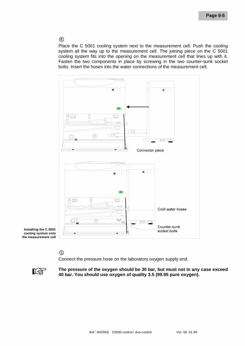
÷Place the C 5001 cooling system next to the measurement cell. Push the coolingsystem all the way up to the measurement cell. The joining piece on the C 5001cooling system fits into the opening on the measurement cell that lines up with it.Fasten the two components in place by screwing in the two counter-sunk socketbolts. Insert the hoses into the water connections of the measurement cell.
ûConnect the pressure hose on the laboratory oxygen supply end.
The pressure of the oxygen should be 30 bar, but must not in any case exceed40 bar. You should use oxygen of quality 3.5 (99.95 pure oxygen).+
Installing the C 5001cooling system onto
the measurement cell
8 Setting up and placing in service
IKA-WERKE C5000 control / duo-control Ver. 06 01.99
Page 8-6
8.2 Setting up package 2
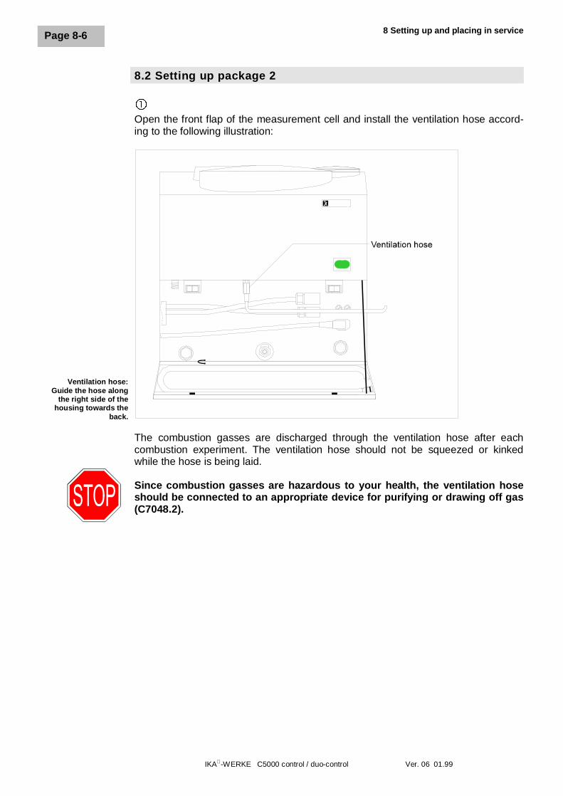
�Open the front flap of the measurement cell and install the ventilation hose accord-ing to the following illustration:
The combustion gasses are discharged through the ventilation hose after eachcombustion experiment. The ventilation hose should not be squeezed or kinkedwhile the hose is being laid.
Since combustion gasses are hazardous to your health, the ventilation hoseshould be connected to an appropriate device for purifying or drawing off gas(C7048.2).
Ventilation hose:Guide the hose along
the right side of thehousing towards the
back.
IKA-WERKE C5000 control / duo-control Ver. 06 01.99
Page 8-7
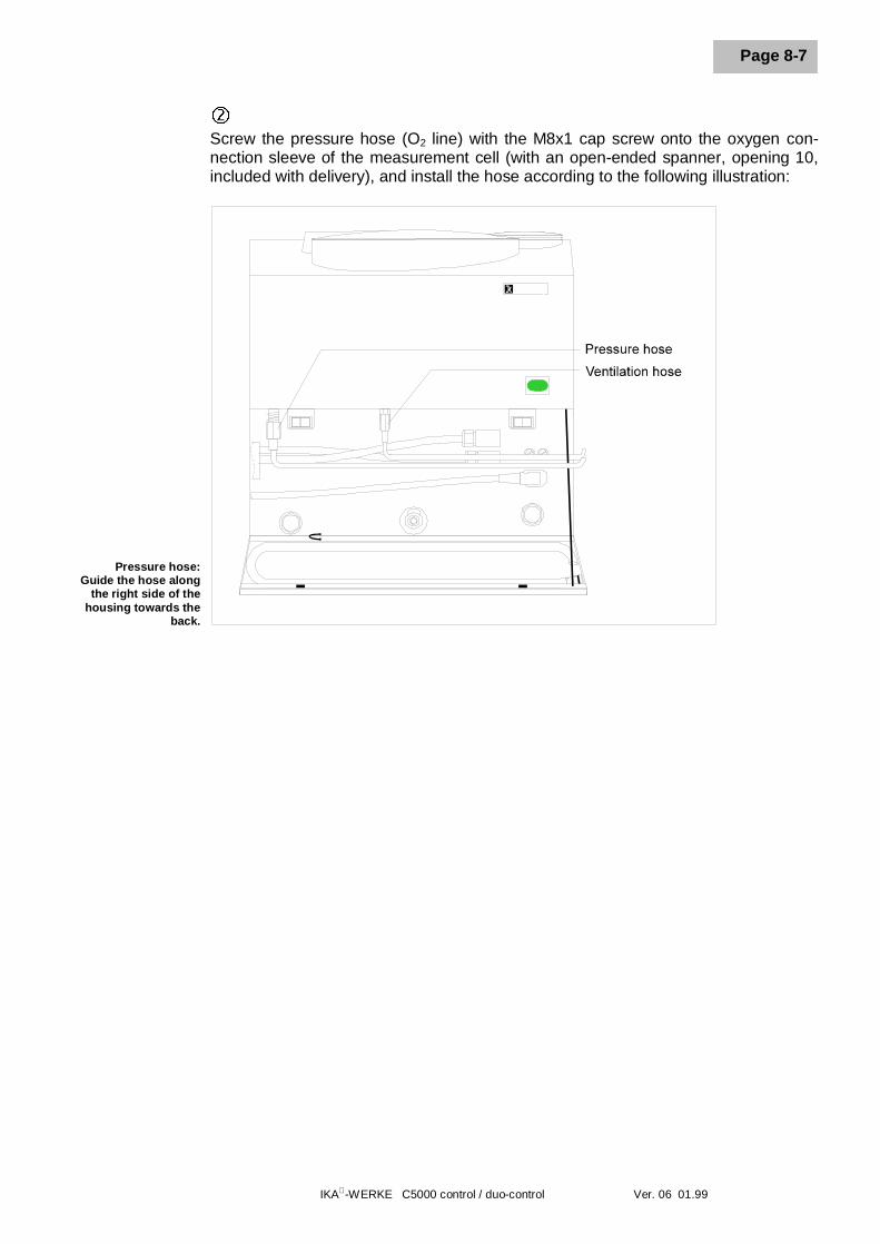
ôScrew the pressure hose (O2 line) with the M8x1 cap screw onto the oxygen con-nection sleeve of the measurement cell (with an open-ended spanner, opening 10,included with delivery), and install the hose according to the following illustration:
Pressure hose:Guide the hose along
the right side of thehousing towards the
back.
8 Setting up and placing in service
IKA-WERKE C5000 control / duo-control Ver. 06 01.99
Page 8-8
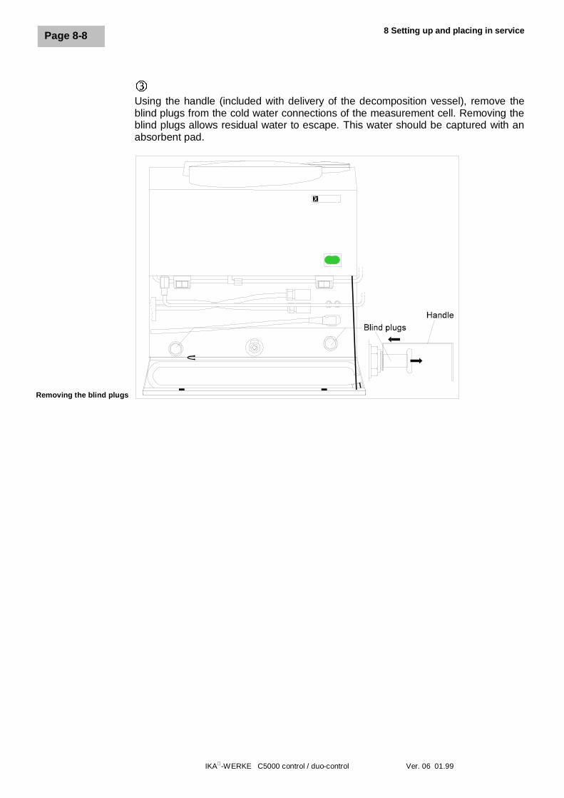
íUsing the handle (included with delivery of the decomposition vessel), remove theblind plugs from the cold water connections of the measurement cell. Removing theblind plugs allows residual water to escape. This water should be captured with anabsorbent pad.
Removing the blind plugs
IKA-WERKE C5000 control / duo-control Ver. 06 01.99
Page 8-9
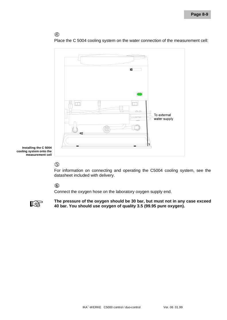
÷Place the C 5004 cooling system on the water connection of the measurement cell:
ûFor information on connecting and operating the C5004 cooling system, see thedatasheet included with delivery.
øConnect the oxygen hose on the laboratory oxygen supply end.
The pressure of the oxygen should be 30 bar, but must not in any case exceed40 bar. You should use oxygen of quality 3.5 (99.95 pure oxygen).+
Installing the C 5004cooling system onto the
measurement cell
8 Setting up and placing in service
IKA-WERKE C5000 control / duo-control Ver. 06 01.99
Page 8-10
8.3 Setting up package 3
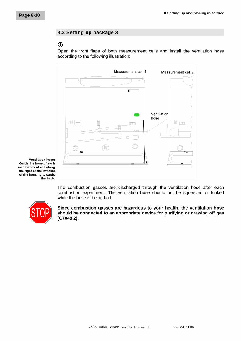
�Open the front flaps of both measurement cells and install the ventilation hoseaccording to the following illustration:
The combustion gasses are discharged through the ventilation hose after eachcombustion experiment. The ventilation hose should not be squeezed or kinkedwhile the hose is being laid.
Since combustion gasses are hazardous to your health, the ventilation hoseshould be connected to an appropriate device for purifying or drawing off gas(C7048.2).
Ventilation hose:Guide the hose of each
measurement cell alongthe right or the left sideof the housing towards
the back.
IKA-WERKE C5000 control / duo-control Ver. 06 01.99
Page 8-11
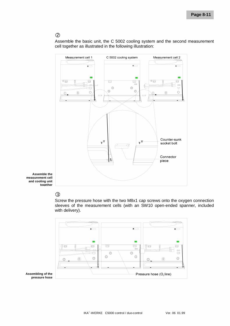
ôAssemble the basic unit, the C 5002 cooling system and the second measurementcell together as illustrated in the following illustration:
íScrew the pressure hose with the two M8x1 cap screws onto the oxygen connectionsleeves of the measurement cells (with an SW10 open-ended spanner, includedwith delivery).
Assembling of thepressure hose
Assemble themeasurement cell
and cooling unittogether
8 Setting up and placing in service
IKA-WERKE C5000 control / duo-control Ver. 06 01.99
Page 8-12
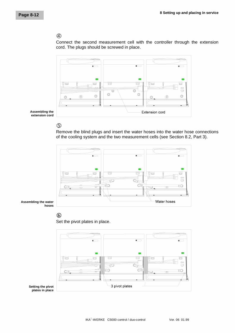
÷Connect the second measurement cell with the controller through the extensioncord. The plugs should be screwed in place.
ûRemove the blind plugs and insert the water hoses into the water hose connectionsof the cooling system and the two measurement cells (see Section 8.2, Part 3).
øSet the pivot plates in place.
Assembling theextension cord
Assembling the waterhoses
Setting the pivotplates in place
IKA-WERKE C5000 control / duo-control Ver. 06 01.99
Page 8-13
ùConnect the pressure hose on the laboratory oxygen supply end.
The pressure of the oxygen should be 30 bar, but must not in any case exceed40 bar. You should use oxygen of quality 3.5 (99.95 pure oxygen).
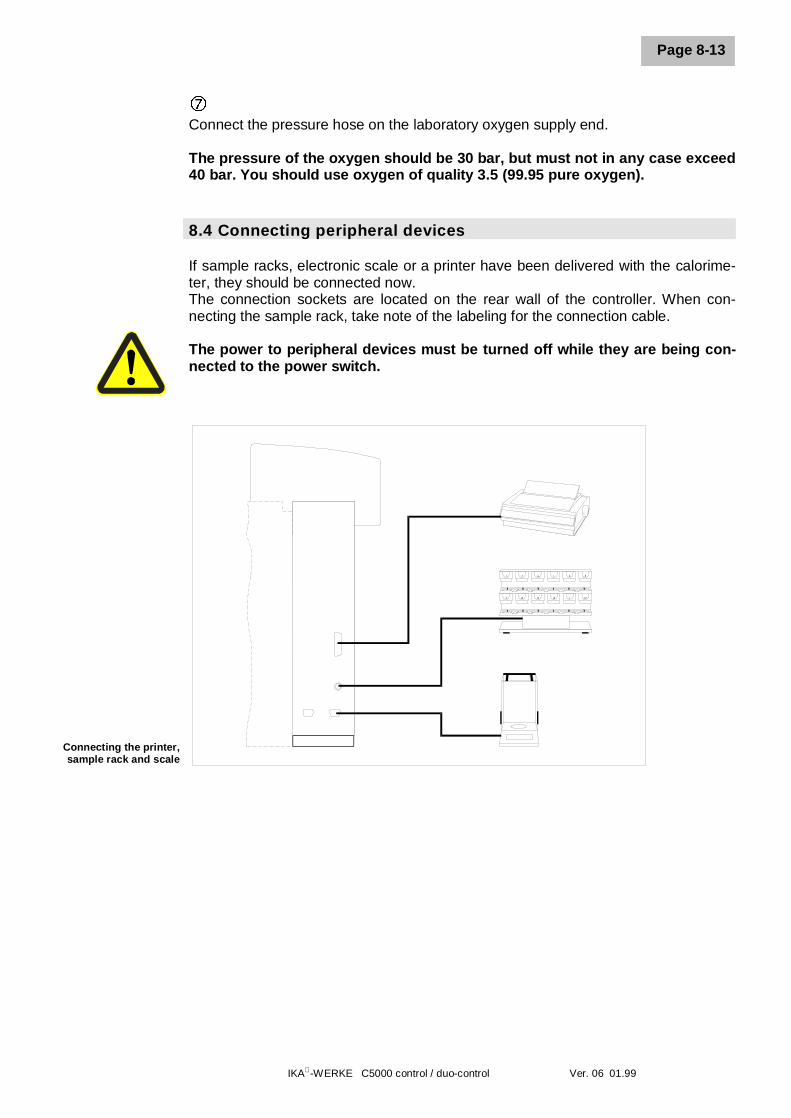
8.4 Connecting peripheral devices
If sample racks, electronic scale or a printer have been delivered with the calorime-ter, they should be connected now.The connection sockets are located on the rear wall of the controller. When con-necting the sample rack, take note of the labeling for the connection cable.
The power to peripheral devices must be turned off while they are being con-nected to the power switch.
Connecting the printer,sample rack and scale
8 Setting up and placing in service
IKA-WERKE C5000 control / duo-control Ver. 06 01.99
Page 8-14
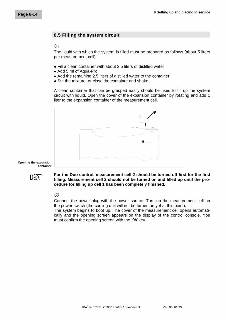
8.5 Filling the system circuit
�The liquid with which the system is filled must be prepared as follows (about 5 litersper measurement cell):
l Fill a clean container with about 2.5 liters of distilled waterl Add 5 ml of Aqua-Prol Add the remaining 2.5 liters of distilled water to the containerl Stir the mixture, or close the container and shake
A clean container that can be grasped easily should be used to fill up the systemcircuit with liquid. Open the cover of the expansion container by rotating and add 1liter to the expansion container of the measurement cell.
For the Duo-control, measurement cell 2 should be turned off first for the firstfilling. Measurement cell 2 should not be turned on and filled up until the pro-cedure for filling up cell 1 has been completely finished.
ôConnect the power plug with the power source. Turn on the measurement cell onthe power switch (the cooling unit will not be turned on yet at this point).The system begins to boot up. The cover of the measurement cell opens automati-cally and the opening screen appears on the display of the control console. Youmust confirm the opening screen with the OK key.
Opening the expansioncontainer
+
IKA-WERKE C5000 control / duo-control Ver. 06 01.99
Page 8-15
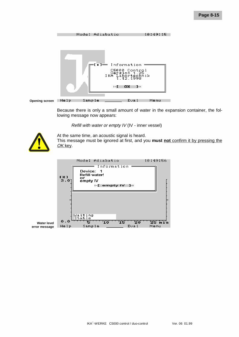
Opening screen
Because there is only a small amount of water in the expansion container, the fol-lowing message now appears:
Refill with water or empty IV (IV - inner vessel)
At the same time, an acoustic signal is heard.This message must be ignored at first, and you must not confirm it by pressing theOK key.
Water levelerror message
8 Setting up and placing in service
IKA-WERKE C5000 control / duo-control Ver. 06 01.99
Page 8-16
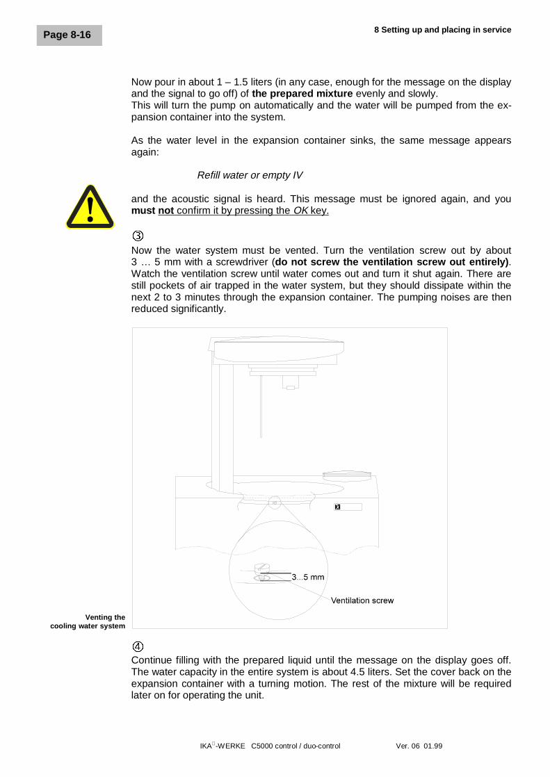
Now pour in about 1 – 1.5 liters (in any case, enough for the message on the displayand the signal to go off) of the prepared mixture evenly and slowly.This will turn the pump on automatically and the water will be pumped from the ex-pansion container into the system.
As the water level in the expansion container sinks, the same message appearsagain:
Refill water or empty IV
and the acoustic signal is heard. This message must be ignored again, and youmust not confirm it by pressing the OK key.
íNow the water system must be vented. Turn the ventilation screw out by about3 … 5 mm with a screwdriver (do not screw the ventilation screw out entirely).Watch the ventilation screw until water comes out and turn it shut again. There arestill pockets of air trapped in the water system, but they should dissipate within thenext 2 to 3 minutes through the expansion container. The pumping noises are thenreduced significantly.
÷Continue filling with the prepared liquid until the message on the display goes off.The water capacity in the entire system is about 4.5 liters. Set the cover back on theexpansion container with a turning motion. The rest of the mixture will be requiredlater on for operating the unit.
Venting thecooling water system
IKA-WERKE C5000 control / duo-control Ver. 06 01.99
Page 8-17
The sieve insert in the filling sleeve of the expansion container must bechecked when refilling the system for deposits, etc. Observe the references inthis regard in Section 14 “Care and Maintenance”.
During routine operation, liquid is lost by evaporation and by adhering to the decom-position vessel.
During normal operation, if this error message appears on the display:
Refill water or empty IV
at least 50 ml of the mixture should be added to the expansion container. If themessage does not disappear, repeat the filling process in increments of 50 ml.
û
At this point, the cooling unit is turned on. The system is now ready for operation.
+
8 Setting up and placing in service
IKA-WERKE C5000 control / duo-control Ver. 06 01.99
Page 8-18
8.6 Control and display elements
Before you continue with the next steps in preparing the system for operation, youshould become familiar with the display and control console.
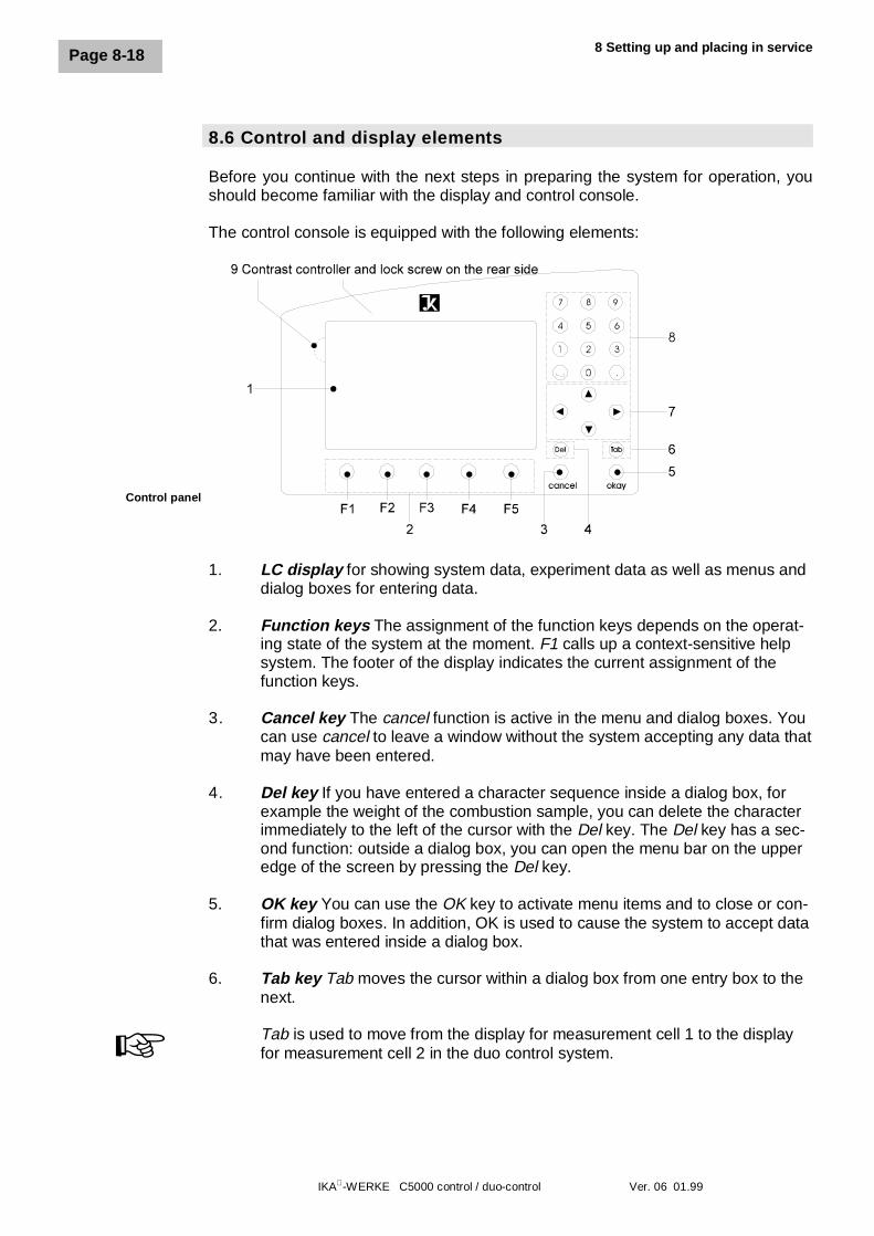
The control console is equipped with the following elements:
1. LC display for showing system data, experiment data as well as menus anddialog boxes for entering data.
2. Function keys The assignment of the function keys depends on the operat-ing state of the system at the moment. F1 calls up a context-sensitive helpsystem. The footer of the display indicates the current assignment of thefunction keys.
3. Cancel key The cancel function is active in the menu and dialog boxes. Youcan use cancel to leave a window without the system accepting any data thatmay have been entered.
4. Del key If you have entered a character sequence inside a dialog box, forexample the weight of the combustion sample, you can delete the characterimmediately to the left of the cursor with the Del key. The Del key has a sec-ond function: outside a dialog box, you can open the menu bar on the upperedge of the screen by pressing the Del key.
5. OK key You can use the OK key to activate menu items and to close or con-firm dialog boxes. In addition, OK is used to cause the system to accept datathat was entered inside a dialog box.
6. Tab key Tab moves the cursor within a dialog box from one entry box to thenext.
Tab is used to move from the display for measurement cell 1 to the displayfor measurement cell 2 in the duo control system.+
Control panel
IKA-WERKE C5000 control / duo-control Ver. 06 01.99
Page 8-19
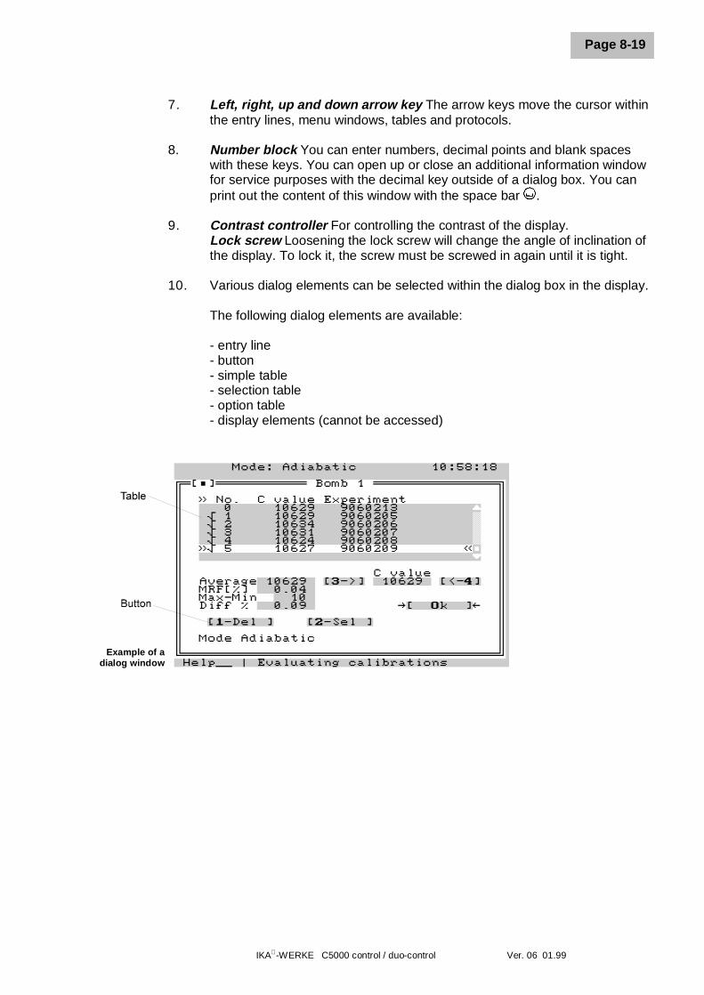
7. Left, right, up and down arrow key The arrow keys move the cursor withinthe entry lines, menu windows, tables and protocols.
8. Number block You can enter numbers, decimal points and blank spaceswith these keys. You can open up or close an additional information windowfor service purposes with the decimal key outside of a dialog box. You canprint out the content of this window with the space bar .
9. Contrast controller For controlling the contrast of the display.Lock screw Loosening the lock screw will change the angle of inclination ofthe display. To lock it, the screw must be screwed in again until it is tight.
10. Various dialog elements can be selected within the dialog box in the display.
The following dialog elements are available:
- entry line- button- simple table- selection table- option table- display elements (cannot be accessed)
Example of adialog window
8 Setting up and placing in service
IKA-WERKE C5000 control / duo-control Ver. 06 01.99
Page 8-20
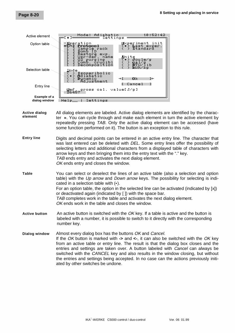
All dialog elements are labeled. Active dialog elements are identified by the charac-ter ». You can cycle through and make each element in turn the active element byrepeatedly pressing TAB. Only the active dialog element can be accessed (havesome function performed on it). The button is an exception to this rule.
Digits and decimal points can be entered in an active entry line. The character thatwas last entered can be deleted with DEL. Some entry lines offer the possibility ofselecting letters and additional characters from a displayed table of characters witharrow keys and then bringing them into the entry text with the “.” key.TAB ends entry and activates the next dialog element.OK ends entry and closes the window.
You can select or deselect the lines of an active table (also a selection and optiontable) with the Up arrow and Down arrow keys. The possibility for selecting is indi-cated in a selection table with (•).For an option table, the option in the selected line can be activated (indicated by [x])or deactivated again (indicated by [ ]) with the space bar.TAB completes work in the table and activates the next dialog element.OK ends work in the table and closes the window.
An active button is switched with the OK key. If a table is active and the button islabeled with a number, it is possible to switch to it directly with the correspondingnumber key.
Almost every dialog box has the buttons OK and Cancel.If the OK button is marked with -> and <-, it can also be switched with the OK keyfrom an active table or entry line. The result is that the dialog box closes and theentries and settings are taken over. A button labeled with Cancel can always beswitched with the CANCEL key and also results in the window closing, but withoutthe entries and settings being accepted. In no case can the actions previously initi-ated by other switches be undone.
Active dialogelement
Entry line
Table
Active button
Dialog window
Example of adialog window
IKA-WERKE C5000 control / duo-control Ver. 06 01.99
Page 8-21
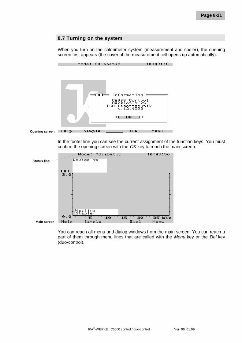
8.7 Turning on the system
When you turn on the calorimeter system (measurement and cooler), the openingscreen first appears (the cover of the measurement cell opens up automatically).
Opening screen
In the footer line you can see the current assignment of the function keys. You mustconfirm the opening screen with the OK key to reach the main screen.
You can reach all menu and dialog windows from the main screen. You can reach apart of them through menu lines that are called with the Menu key or the Del key(duo-control).
Main screen
8 Setting up and placing in service
IKA-WERKE C5000 control / duo-control Ver. 06 01.99
Page 8-22
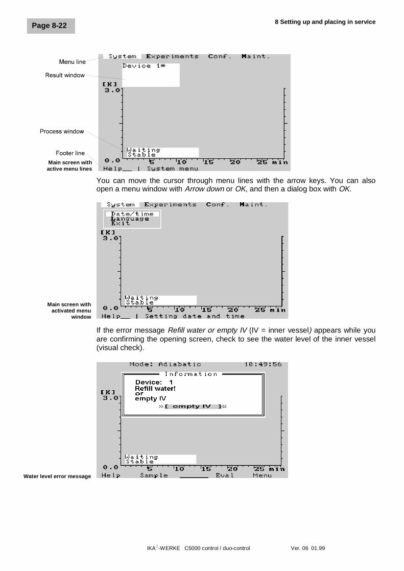
You can move the cursor through menu lines with the arrow keys. You can alsoopen a menu window with Arrow down or OK, and then a dialog box with OK.
Main screen withactivated menu
window
If the error message Refill water or empty IV (IV = inner vessel) appears while youare confirming the opening screen, check to see the water level of the inner vessel(visual check).
Water level error message
Main screen withactive menu lines
IKA-WERKE C5000 control / duo-control Ver. 06 01.99
Page 8-23
If it should happen to be higher than 1 cm above the bottom of the vessel, thenplease confirm the error message in the display with the OK key.In this case, the remainder of the water is pumped out of the inner vessel into theexpansion container.
If the error message is not eliminated in spite of the inner vessel being emptied, youmust pour 50 ml of the prepared liquid into the expansion container. The messagethen disappears.If this quantity alone is not sufficient, then repeat the last step in 50-ml increments.
Before you pour the liquid into the expansion container, however, alwayscheck the water level in the inner vessel first. If you should find a residual vol-ume of water there and other additional liquid is added to the expansion con-tainer, this could cause the system to overflow the next time the inner vesselis emptied.
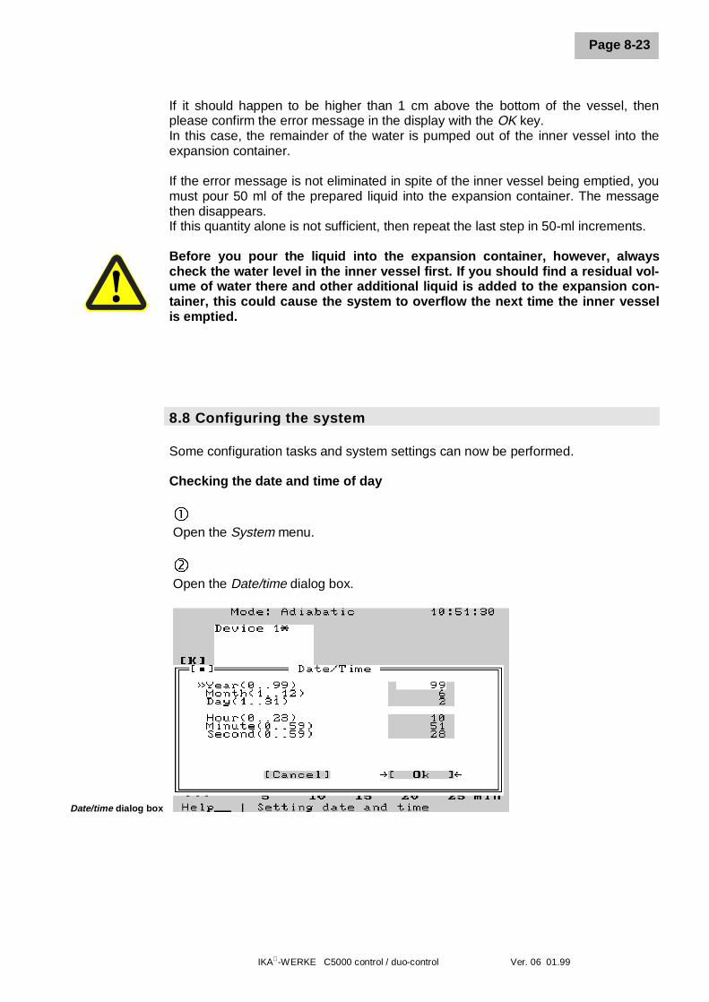
8.8 Configuring the system
Some configuration tasks and system settings can now be performed.
Checking the date and time of day
� Open the System menu.
ô Open the Date/time dialog box.
Date/time dialog box
8 Setting up and placing in service
IKA-WERKE C5000 control / duo-control Ver. 06 01.99
Page 8-24
Meaning of the entries:Year (0…99) number of the year, for example 97 = 1997, 02 = 2002Month (1…12) Calendar month, for example 03 = MarchDay (1…31) Day of the monthHour (0…23) Hour entry; 0 = midnightMinute (0…59) Minute entrySecond (0…59) Second entry
íCompare the entries with the current date and time of day and correct the entries asneeded. If you confirm the dialog box with OK, the system clock and calendar willaccept these values.
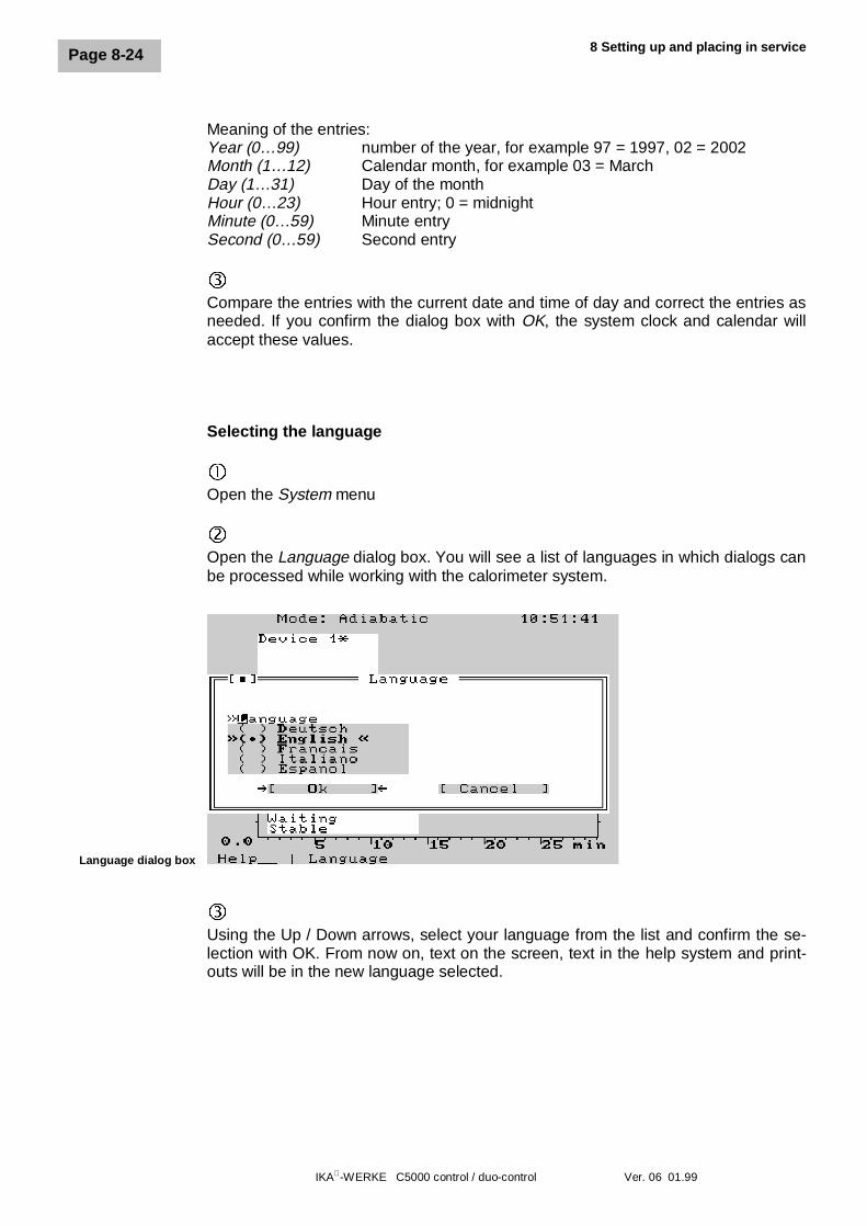
Selecting the language
�Open the System menu
ôOpen the Language dialog box. You will see a list of languages in which dialogs canbe processed while working with the calorimeter system.
Language dialog box
íUsing the Up / Down arrows, select your language from the list and confirm the se-lection with OK. From now on, text on the screen, text in the help system and print-outs will be in the new language selected.
IKA-WERKE C5000 control / duo-control Ver. 06 01.99
Page 8-25
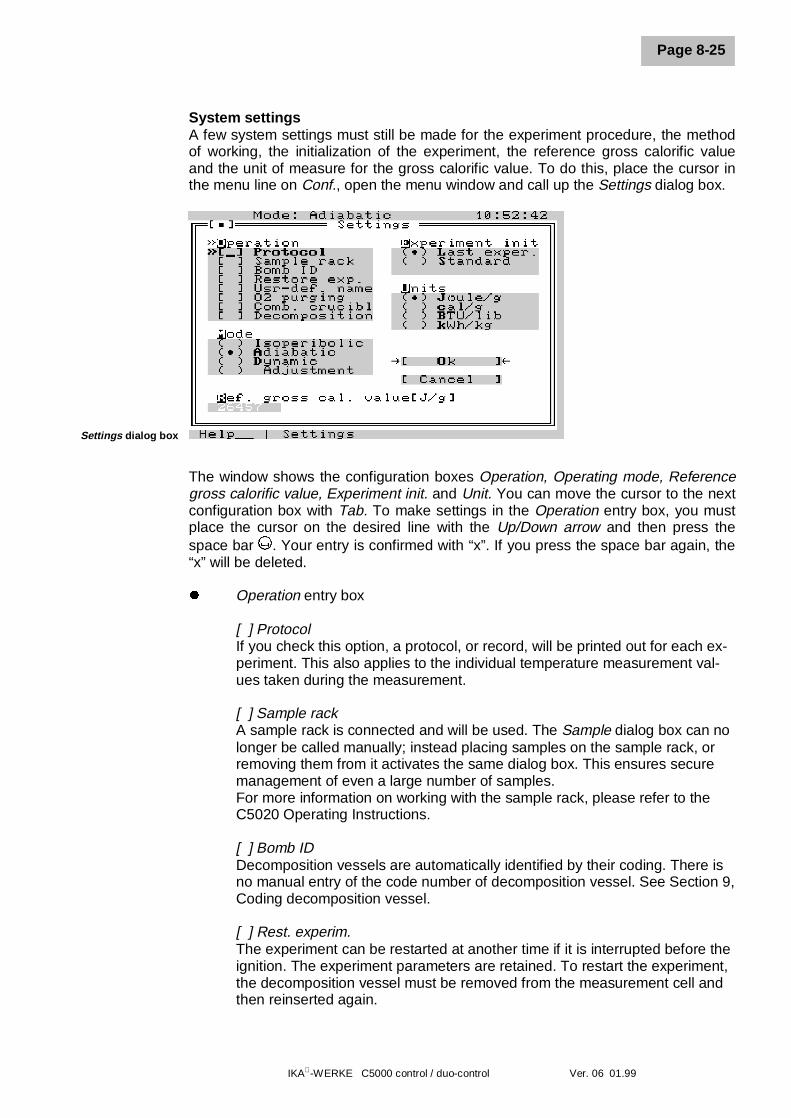
System settingsA few system settings must still be made for the experiment procedure, the methodof working, the initialization of the experiment, the reference gross calorific valueand the unit of measure for the gross calorific value. To do this, place the cursor inthe menu line on Conf., open the menu window and call up the Settings dialog box.
Settings dialog box
The window shows the configuration boxes Operation, Operating mode, Referencegross calorific value, Experiment init. and Unit. You can move the cursor to the nextconfiguration box with Tab. To make settings in the Operation entry box, you mustplace the cursor on the desired line with the Up/Down arrow and then press thespace bar . Your entry is confirmed with “x”. If you press the space bar again, the“x” will be deleted.
l Operation entry box
[ ] ProtocolIf you check this option, a protocol, or record, will be printed out for each ex-periment. This also applies to the individual temperature measurement val-ues taken during the measurement.
[ ] Sample rackA sample rack is connected and will be used. The Sample dialog box can nolonger be called manually; instead placing samples on the sample rack, orremoving them from it activates the same dialog box. This ensures securemanagement of even a large number of samples.For more information on working with the sample rack, please refer to theC5020 Operating Instructions.
[ ] Bomb IDDecomposition vessels are automatically identified by their coding. There isno manual entry of the code number of decomposition vessel. See Section 9,Coding decomposition vessel.
[ ] Rest. experim.The experiment can be restarted at another time if it is interrupted before theignition. The experiment parameters are retained. To restart the experiment,the decomposition vessel must be removed from the measurement cell andthen reinserted again.
8 Setting up and placing in service
IKA-WERKE C5000 control / duo-control Ver. 06 01.99
Page 8-26
[ ] User def. nameHere you can specify whether you will enter the Sample name yourself in theSample name entry box and in the Sample dialog box, or whether the systemwill automatically assign the Sample name. If you do not select this option,the system assigns experiment numbers in the Sample name box.
[ ] O2 rinsingWith this option, the decomposition vessel is briefly filled with oxygen, afterwhich the oxygen is released each time, before the actual filling with oxygen.The purpose of this is to remove atmospheric nitrogen.
[ ] combustible crucibleIf you are using a combustible crucible, the default entry for extraneous en-ergy is 70 J (electrical ignition energy). Otherwise it is 120 J (70 J + 50 J).The additional 50 J are derived from burning the cotton thread.
[ ] DecompositionIf the sample is to be subjected to a subsequent decomposition after it hasundergone combustion, the decomposition vessel must be depressurizedoutside of the calorimeter. To do this, a special depressurization stationC5030 is connected (there is no automatic depressurization of the decompo-sition vessel).
l Operating mode entry boxIn this box, you can select an option for the temperature control of the waterjacket in the outer vessel. The following options are available:
( ) Isoperibolic The temperature of the water jacket is regulated to aconstant temperature.
( ) Adiabatic The temperature of the water jacket is regulated ad-justed to match the temperature of the inner vessel.
( ) Dynamic The combustion experiments are performed accordingto a quick procedure.
( ) Adjustment Internal parameters of temperature control are deter-mined for this option. The device has been adjustedduring the functional test in the factory. It possesses atemperature compensation so that under normal labo-ratory circumstances no adjustment is required when itis first placed in service. For more detailed information,see Section 14.3, Adjustment.
l Reference gross calorific value [J/g] entry boxIn most cases, certified benzoic acid is used. The indicated gross calorificvalue should be entered. If you are working with another reference combus-tion substance, you must enter the gross calorific value of this combustionsubstance here yourself.
l Experiment init. entry box.You can use the experiment initialization to specify how the parameters Userand Sample properties should be set in the Sample dialog box, as well as allparameters in the Experiments dialog box. These setting options are dis-
IKA-WERKE C5000 control / duo-control Ver. 06 01.99
Page 8-27
cussed again in Section 11, “Determining gross calorific values”. The follow-ing options are available:
( ) Last experim. The system accepts the User and Sample propertiesparameters for a new experiment as well as the indi-cated post-experiment parameters of the last experi-ment to be evaluated.If the User def. name option has been selected, thesample name is also accepted. This must then be ed-ited or reentered to make up for the difference.
( ) Standard The post-experiment parameters are set to 0 for a newexperiment. The extraneous energy is set to 120 J /70 J, and the User and Sample properties boxes in theSample dialog box remain empty.
l Unit entry boxThe unit of measure for the caloric results is specified here. This refers onlyto the result protocols! Available for selection:
( ) Joules/g( ) cal/g( ) BTU/lib( ) kWH/kg
When you click on OK, the calorimeter system accepts the settings and closes thedialog box.
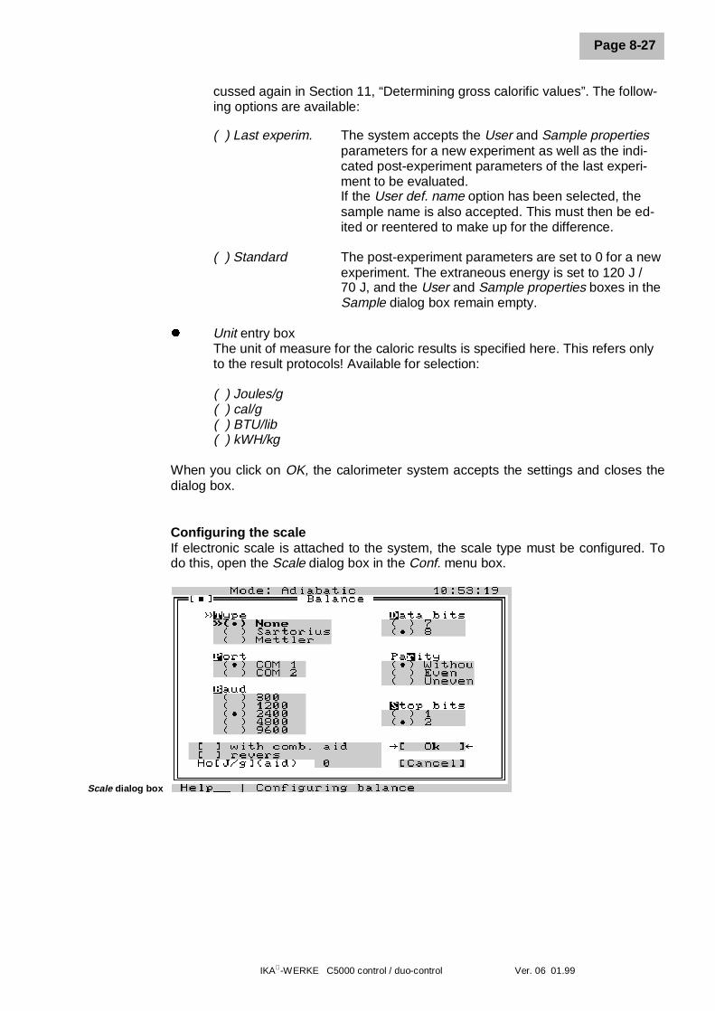
Configuring the scaleIf electronic scale is attached to the system, the scale type must be configured. Todo this, open the Scale dialog box in the Conf. menu box.
Scale dialog box
8 Setting up and placing in service
IKA-WERKE C5000 control / duo-control Ver. 06 01.99
Page 8-28
The window displays the configuration windows Type, Port, Baud, Data bits, Parity,and Stop bits. The parameters you select here must agree with the interface pa-rameters of the attached scale. Please refer to the scale manual for the parameters.To move the cursor to the next configuration box, press Tab. Up/Down arrow movesthe cursor within a configuration box. If you leave a box with Tab, the current settingis retained in the box.You can make the following settings with the configuration boxes:
l Type configuration boxHere you can indicate which scale is connected to the system. Either noscale or one of the types indicated are connected.
l Port configuration boxNo entry is possible in the Port box. The scale is always attached to COM1.
l Baud configuration boxThe data transmission rate between the scale and the calorimeter system isadjustable to 300, 1200, 2400, 4800, 9600 and 19200 Bit/s.
l Data bits configuration boxHere you can select whether data will be transferred in 7-bit or 8-bit format.
l Parity configuration boxIndicate whether the transferred data should be accepted without a check forparity by the calorimeter system, or whether a check should be performed foreven or odd parity.
l Stop bits configuration boxSelect either 1 or 2 stop bits for the data transfer protocol. If you are using acombustion aid or the combustible crucible, it is possible to record the weightof the combustion aid or the combustible crucible by using a special weighingmode and to calculate the extraneous energy resulting from this measure-ment automatically.
l With combustion aid configuration boxIf the option With combustion aid is marked, the values of the scale aretransferred in the following order:1. “Weighed in combustion aid”2. “Weighed in combustion aid + weighed in sample”
l Reverse configuration boxIf the box reverse is marked in addition to the configuration box With com-bustion aid, scale values will be transferred in the following order:1. “Weighed in sample”2. “Weighed in sample + weighed in combustion aid”After the transfer, the second measured value appears in the “New meas-urement” dialog box. The calculated value for extraneous energy is alreadyentered there.
IKA-WERKE C5000 control / duo-control Ver. 06 01.99
Page 8-29
l Gross calorific value of the combustion aid configuration boxIn combination with the configuration box With combustion aid, the grosscalorific value of the combustion aid must be entered in this box so that thesystem can calculate the extraneous energy.
IKA-WERKE C5000 control / duo-control Ver. 06 01.99
Page 9-1
9 System calibration
Before it is possible to make precise measurements with the calorimeter system, itmust be calibrated. This is done by burning tablets of certified benzoic acid (seeaccessories) with a known gross calorific value. This makes it possible to determinethe heat capacity (the C value) of the system based on the amount of heat that isrequired to raise the temperature of the calorimeter system by 1 degree Kelvin. Thisvalue is then used for subsequent determinations of gross calorific values.The heat capacity is determined by the measurement cell and the decompositionvessel. It has a considerable effect on the precision of measurement, and must es-pecially be determined when the system is first placed in service, after maintenanceor repair work, and when parts are replaced.
If a measurement cell is being operated with several decomposition vessels,the heat capacity of the system must be determined through calibration foreach individual decomposition vessel. A decomposition vessel should only beused in the measurement cell for which it has also been calibrated.The calorimeter system must be calibrated in each operating mode (adiabatic,isoperibolic and dynamic) in which measurements will later be made. Pleaseobserve the applicable standards in this regard.
Calibration must take place under the same conditions as will be found during sub-sequent experiments. If measured quantities of substances (for example distilledwater or solutions) will be used in the decomposition vessel, exactly the same quan-tity of these substances should be used during calibration.
Calibration notesl In order to achieve precise results, you should take care that the combustion not
exceed an increase in temperature of 4 K. This applies as a rule of thumb if nobenzoic acid is being used during the calibration.
l It should be mentioned here in advance that when determining gross calorificvalues, the increase in temperature must be roughly the same as for the calibra-tion (for example 4 tablets – approximately 1 g of benzoic acid ≈ 2.6 K)
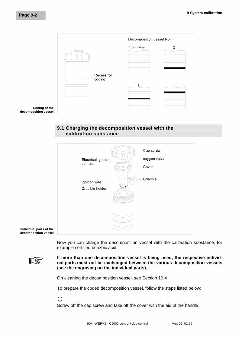
CodingWhen working with the calorimeter system, a maximum of 4 decomposition vesselscan be used. The maximum for the duo-control system is 2 decomposition vesselsper measurement cell. This is possible by coding the decomposition vessels from 1to 4. The system recognizes which decomposition vessel an experiment is beingperformed with and assigns its calibration parameters to it.
Each decomposition vessel must be coded before it is used for the first time.
To do this, attach the black coding rings into the recesses on the decompositionvessel provided for this purpose.
+
+
9 System calibration
IKA-WERKE C5000 control / duo-control Ver. 06 01.99
Page 9-2
9.1 Charging the decomposition vessel with the calibration substance
Now you can charge the decomposition vessel with the calibration substance, forexample certified benzoic acid.
If more than one decomposition vessel is being used, the respective individ-ual parts must not be exchanged between the various decomposition vessels(see the engraving on the individual parts).
On cleaning the decomposition vessel, see Section 10.4
To prepare the coded decomposition vessel, follow the steps listed below:
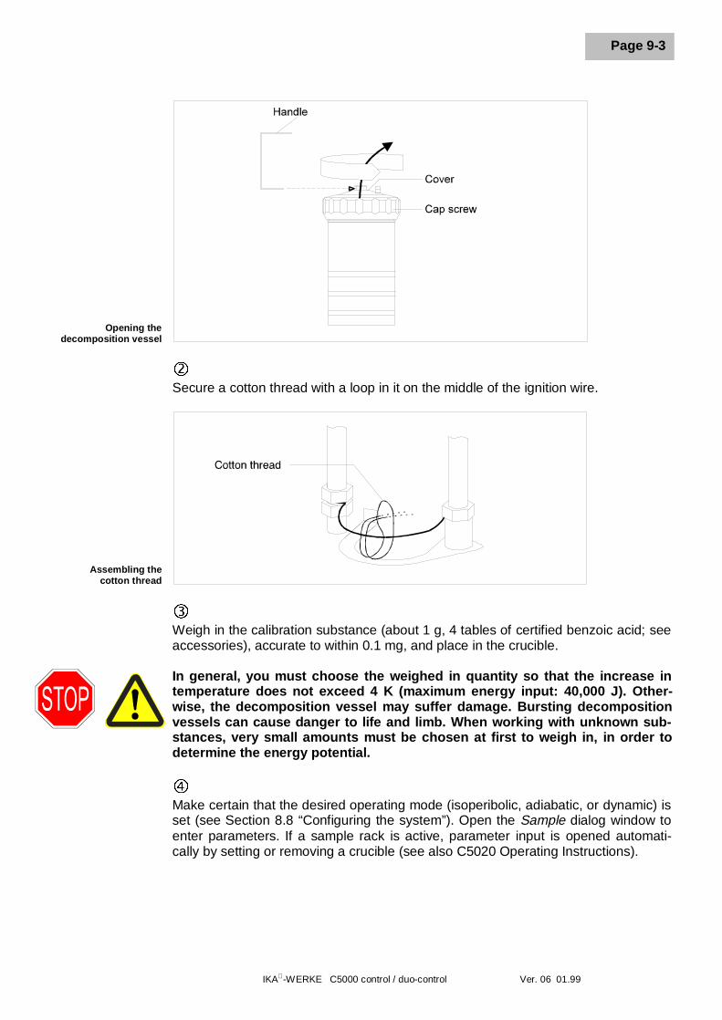
�Screw off the cap screw and take off the cover with the aid of the handle.
+
Coding of thedecomposition vessel
Individual parts of thedecomposition vessel
IKA-WERKE C5000 control / duo-control Ver. 06 01.99
Page 9-3
ôSecure a cotton thread with a loop in it on the middle of the ignition wire.
íWeigh in the calibration substance (about 1 g, 4 tables of certified benzoic acid; seeaccessories), accurate to within 0.1 mg, and place in the crucible.
In general, you must choose the weighed in quantity so that the increase intemperature does not exceed 4 K (maximum energy input: 40,000 J). Other-wise, the decomposition vessel may suffer damage. Bursting decompositionvessels can cause danger to life and limb. When working with unknown sub-stances, very small amounts must be chosen at first to weigh in, in order todetermine the energy potential.
÷Make certain that the desired operating mode (isoperibolic, adiabatic, or dynamic) isset (see Section 8.8 “Configuring the system”). Open the Sample dialog window toenter parameters. If a sample rack is active, parameter input is opened automati-cally by setting or removing a crucible (see also C5020 Operating Instructions).
Opening thedecomposition vessel
Assembling thecotton thread
9 System calibration
IKA-WERKE C5000 control / duo-control Ver. 06 01.99
Page 9-4
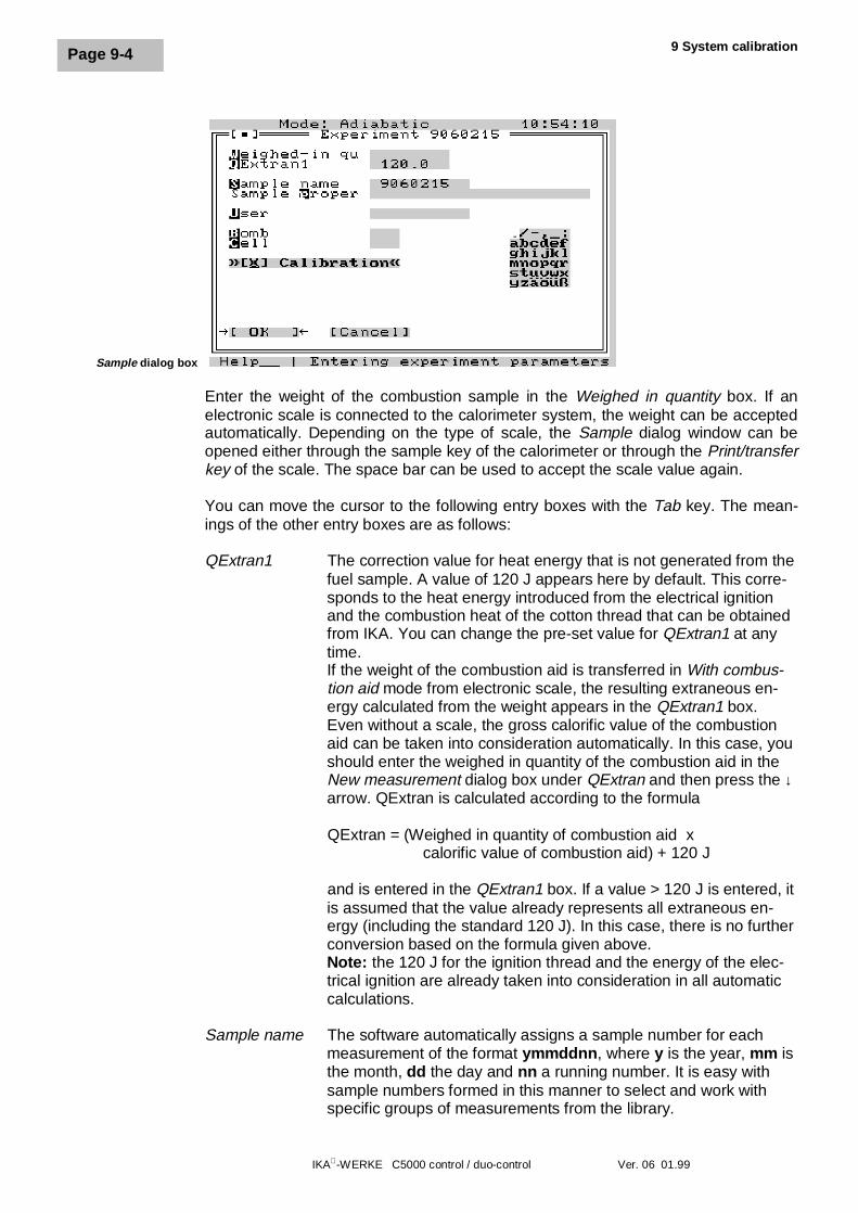
Sample dialog box
Enter the weight of the combustion sample in the Weighed in quantity box. If anelectronic scale is connected to the calorimeter system, the weight can be acceptedautomatically. Depending on the type of scale, the Sample dialog window can beopened either through the sample key of the calorimeter or through the Print/transferkey of the scale. The space bar can be used to accept the scale value again.
You can move the cursor to the following entry boxes with the Tab key. The mean-ings of the other entry boxes are as follows:
QExtran1 The correction value for heat energy that is not generated from thefuel sample. A value of 120 J appears here by default. This corre-sponds to the heat energy introduced from the electrical ignitionand the combustion heat of the cotton thread that can be obtainedfrom IKA. You can change the pre-set value for QExtran1 at anytime.If the weight of the combustion aid is transferred in With combus-tion aid mode from electronic scale, the resulting extraneous en-ergy calculated from the weight appears in the QExtran1 box.Even without a scale, the gross calorific value of the combustionaid can be taken into consideration automatically. In this case, youshould enter the weighed in quantity of the combustion aid in theNew measurement dialog box under QExtran and then press the ↓arrow. QExtran is calculated according to the formula
QExtran = (Weighed in quantity of combustion aid x calorific value of combustion aid) + 120 J
and is entered in the QExtran1 box. If a value > 120 J is entered, itis assumed that the value already represents all extraneous en-ergy (including the standard 120 J). In this case, there is no furtherconversion based on the formula given above.Note: the 120 J for the ignition thread and the energy of the elec-trical ignition are already taken into consideration in all automaticcalculations.
Sample name The software automatically assigns a sample number for eachmeasurement of the format ymmddnn, where y is the year, mm isthe month, dd the day and nn a running number. It is easy withsample numbers formed in this manner to select and work withspecific groups of measurements from the library.
IKA-WERKE C5000 control / duo-control Ver. 06 01.99
Page 9-5
If you select the option User def. name under Menu, Configuration,Settings, you can assign your own numbers or names for meas-urements (automatic numbering continues to run in the back-ground, but is no longer taken into consideration).If you have selected the option Last in addition under Menu, Con-figuration, Settings, Experiment init., the number of the last ex-periment appears as a suggestion for the current measurement. Ifyou do not edit this suggestion, the sample number will be thesame for all measurements!
Example of a Sample name = 6052401
1 Number of the year, 6 = 199605 Month, 0 … 12, 05 = May24 Day of the month, here May 24th
01 The running experiment number
Sample Any additional information on the sample. You can select lettersproperties and characters from the character table with the arrow keys. With
the decimal point key, the system accepts the selected charactersinto the entry field (max. 40 characters).
User The name of the user (up to 8 characters). Entry as forSample properties.
[ ] Calibration Mark this box with space bar for the system to use the experimentfor calibration.
OK causes the system to accept entries in the dialog box.
ûThe message Bomb ↓ appears from then on at the bottom of the screen. Thismeans that from now on, the decomposition vessel can be suspended in the meas-urement cell cover.
øIf additional amounts of distilled water, solutions, etc. will be used in subsequentcombustion experiments, the same quantity of the same substance should be in-cluded now in the decomposition vessel. The system should be calibrated in thesame state in which you intend to be working later. If the operating mode changes(with/without an amount of water) the calibration should also be repeated.
To increase the life of parts subject to wear and tear (O rings, seals, etc.), werecommend in general that you always work with a measured amount of waterin the system.
ùPlace the crucible in the crucible holder.
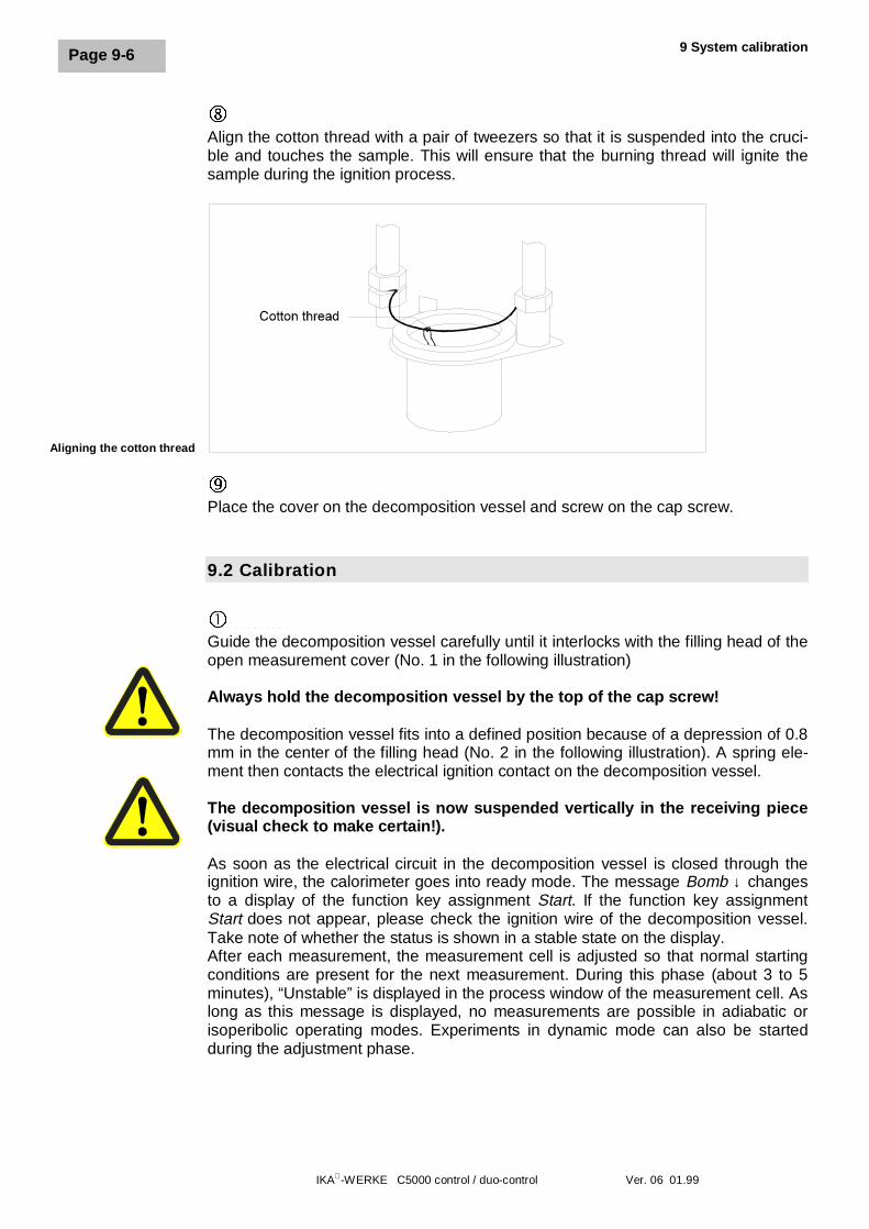
9 System calibration
IKA-WERKE C5000 control / duo-control Ver. 06 01.99
Page 9-6
îAlign the cotton thread with a pair of tweezers so that it is suspended into the cruci-ble and touches the sample. This will ensure that the burning thread will ignite thesample during the ignition process.
üPlace the cover on the decomposition vessel and screw on the cap screw.
9.2 Calibration
��ôí÷ûøùîüü
Guide the decomposition vessel carefully until it interlocks with the filling head of theopen measurement cover (No. 1 in the following illustration)
Always hold the decomposition vessel by the top of the cap screw!
The decomposition vessel fits into a defined position because of a depression of 0.8mm in the center of the filling head (No. 2 in the following illustration). A spring ele-ment then contacts the electrical ignition contact on the decomposition vessel.
The decomposition vessel is now suspended vertically in the receiving piece(visual check to make certain!).
As soon as the electrical circuit in the decomposition vessel is closed through theignition wire, the calorimeter goes into ready mode. The message Bomb ↓ changesto a display of the function key assignment Start. If the function key assignmentStart does not appear, please check the ignition wire of the decomposition vessel.Take note of whether the status is shown in a stable state on the display.After each measurement, the measurement cell is adjusted so that normal startingconditions are present for the next measurement. During this phase (about 3 to 5minutes), “Unstable” is displayed in the process window of the measurement cell. Aslong as this message is displayed, no measurements are possible in adiabatic orisoperibolic operating modes. Experiments in dynamic mode can also be startedduring the adjustment phase.
Aligning the cotton thread
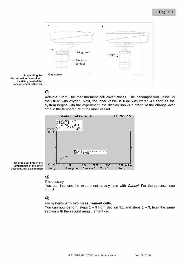
IKA-WERKE C5000 control / duo-control Ver. 06 01.99
Page 9-7
ô Activate Start. The measurement cell cover closes. The decomposition vessel isthen filled with oxygen. Next, the inner vessel is filled with water. As soon as thesystem begins with the experiment, the display shows a graph of the change overtime in the temperature of the inner vessel.
Change over time in thetemperature of the inner
vessel during a calibration
íIf necessary:You can interrupt the experiment at any time with Cancel. For the process, seeitem 5.
÷For systems with two measurement cells:You can now perform steps 1 – 9 from Section 9.1 and steps 1 – 3, from the samesection with the second measurement cell.
Suspending thedecomposition vessel into
the filling head of themeasurement cell cover
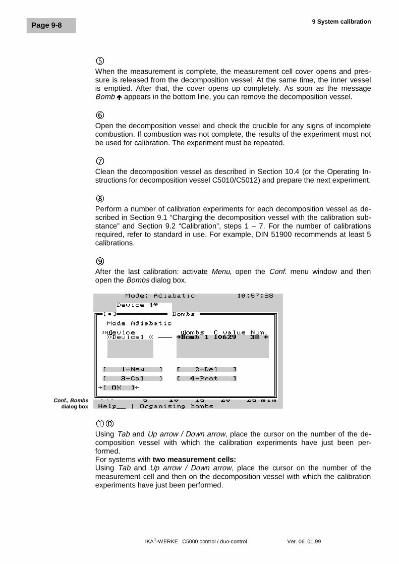
9 System calibration
IKA-WERKE C5000 control / duo-control Ver. 06 01.99
Page 9-8
ûWhen the measurement is complete, the measurement cell cover opens and pres-sure is released from the decomposition vessel. At the same time, the inner vesselis emptied. After that, the cover opens up completely. As soon as the messageBomb Ñ appears in the bottom line, you can remove the decomposition vessel.
øOpen the decomposition vessel and check the crucible for any signs of incompletecombustion. If combustion was not complete, the results of the experiment must notbe used for calibration. The experiment must be repeated.
ùClean the decomposition vessel as described in Section 10.4 (or the Operating In-structions for decomposition vessel C5010/C5012) and prepare the next experiment.
îPerform a number of calibration experiments for each decomposition vessel as de-scribed in Section 9.1 “Charging the decomposition vessel with the calibration sub-stance” and Section 9.2 “Calibration”, steps 1 – 7. For the number of calibrationsrequired, refer to standard in use. For example, DIN 51900 recommends at least 5calibrations.
üAfter the last calibration: activate Menu, open the Conf. menu window and thenopen the Bombs dialog box.
Conf., Bombsdialog box
��Using Tab and Up arrow / Down arrow, place the cursor on the number of the de-composition vessel with which the calibration experiments have just been per-formed.For systems with two measurement cells:Using Tab and Up arrow / Down arrow, place the cursor on the number of themeasurement cell and then on the decomposition vessel with which the calibrationexperiments have just been performed.
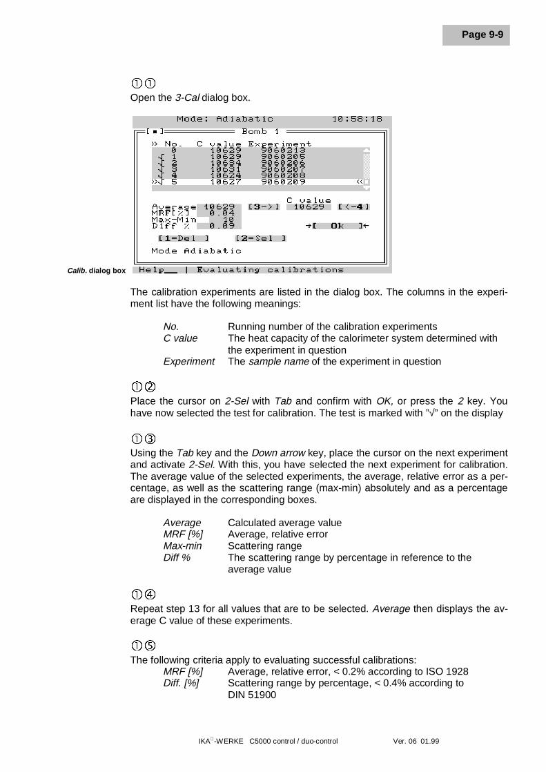
IKA-WERKE C5000 control / duo-control Ver. 06 01.99
Page 9-9
��Open the 3-Cal dialog box.
Calib. dialog box
The calibration experiments are listed in the dialog box. The columns in the experi-ment list have the following meanings:
No. Running number of the calibration experimentsC value The heat capacity of the calorimeter system determined with
the experiment in questionExperiment The sample name of the experiment in question
�ôPlace the cursor on 2-Sel with Tab and confirm with OK, or press the 2 key. Youhave now selected the test for calibration. The test is marked with ”√” on the display
�íUsing the Tab key and the Down arrow key, place the cursor on the next experimentand activate 2-Sel. With this, you have selected the next experiment for calibration.The average value of the selected experiments, the average, relative error as a per-centage, as well as the scattering range (max-min) absolutely and as a percentageare displayed in the corresponding boxes.
Average Calculated average valueMRF [%] Average, relative errorMax-min Scattering rangeDiff % The scattering range by percentage in reference to the
average value
�÷Repeat step 13 for all values that are to be selected. Average then displays the av-erage C value of these experiments.
�ûThe following criteria apply to evaluating successful calibrations:
MRF [%] Average, relative error, < 0.2% according to ISO 1928Diff. [%] Scattering range by percentage, < 0.4% according to
DIN 51900
9 System calibration
IKA-WERKE C5000 control / duo-control Ver. 06 01.99
Page 9-10
Depending on the standard used, other criteria may be of consequence. Normalrequirements for accuracy of the calorimeter are however fulfilled with the valuesgiven above.
�øUsing Tab, place the cursor on the button [3È ] and confirm with OK or press 3. Thiscauses the average value from the selected calibration experiments to be assignedto the calorimeter system as the system heat capacity, or C value. If you place thecursor on [Ç 4] and confirm with OK, you can enter the system heat capacity intothe C value box.
�ùPlace the cursor on the experiments that were not used for calculating the averagevalue and delete with 1-Del.
�îExit the dialog box with OK. This ends the system calibration; you can now continuewith determining gross calorific values.
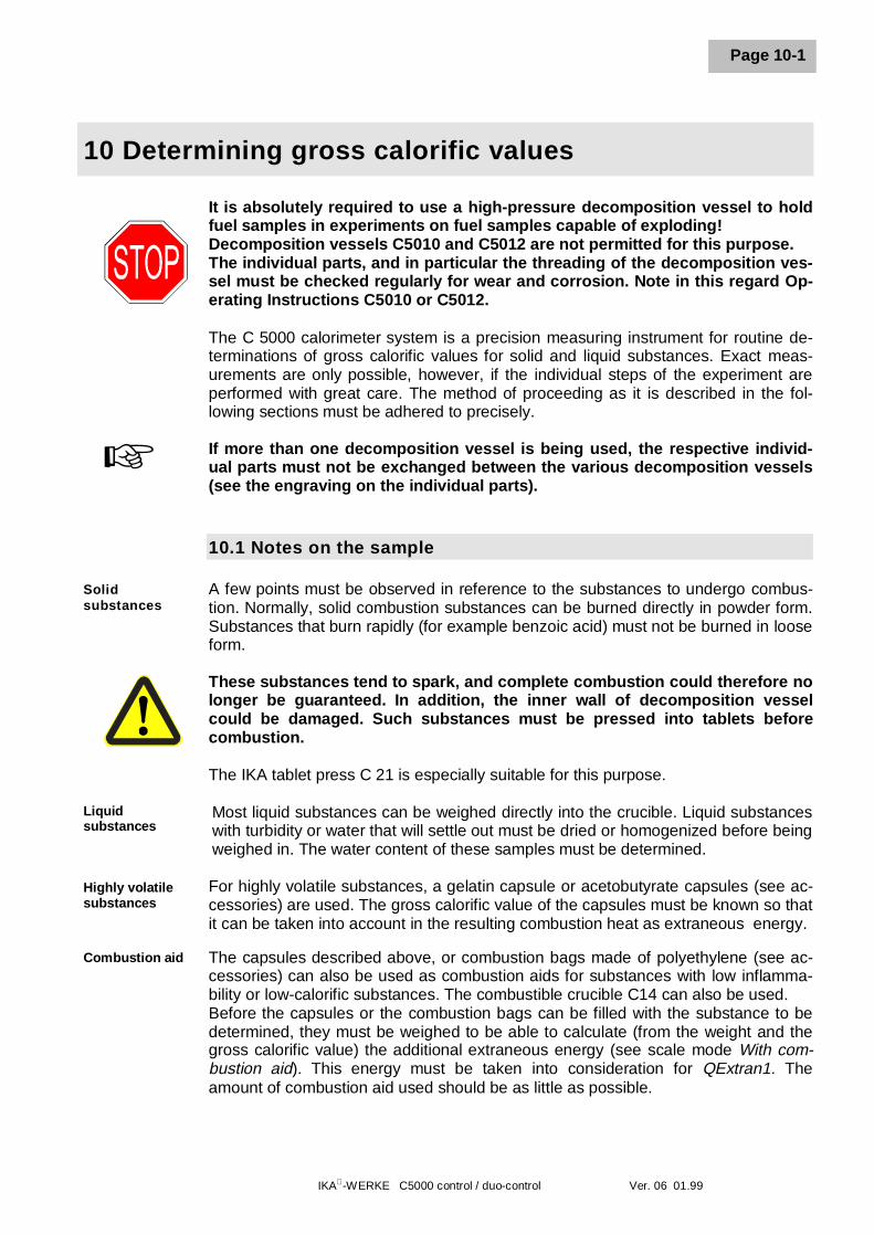
IKA-WERKE C5000 control / duo-control Ver. 06 01.99
Page 10-1
10 Determining gross calorific values
It is absolutely required to use a high-pressure decomposition vessel to holdfuel samples in experiments on fuel samples capable of exploding!Decomposition vessels C5010 and C5012 are not permitted for this purpose.The individual parts, and in particular the threading of the decomposition ves-sel must be checked regularly for wear and corrosion. Note in this regard Op-erating Instructions C5010 or C5012.
The C 5000 calorimeter system is a precision measuring instrument for routine de-terminations of gross calorific values for solid and liquid substances. Exact meas-urements are only possible, however, if the individual steps of the experiment areperformed with great care. The method of proceeding as it is described in the fol-lowing sections must be adhered to precisely.
If more than one decomposition vessel is being used, the respective individ-ual parts must not be exchanged between the various decomposition vessels(see the engraving on the individual parts).
10.1 Notes on the sample
A few points must be observed in reference to the substances to undergo combus-tion. Normally, solid combustion substances can be burned directly in powder form.Substances that burn rapidly (for example benzoic acid) must not be burned in looseform.
These substances tend to spark, and complete combustion could therefore nolonger be guaranteed. In addition, the inner wall of decomposition vesselcould be damaged. Such substances must be pressed into tablets beforecombustion.
The IKA tablet press C 21 is especially suitable for this purpose.
Most liquid substances can be weighed directly into the crucible. Liquid substanceswith turbidity or water that will settle out must be dried or homogenized before beingweighed in. The water content of these samples must be determined.
For highly volatile substances, a gelatin capsule or acetobutyrate capsules (see ac-cessories) are used. The gross calorific value of the capsules must be known so thatit can be taken into account in the resulting combustion heat as extraneous energy.
The capsules described above, or combustion bags made of polyethylene (see ac-cessories) can also be used as combustion aids for substances with low inflamma-bility or low-calorific substances. The combustible crucible C14 can also be used.Before the capsules or the combustion bags can be filled with the substance to bedetermined, they must be weighed to be able to calculate (from the weight and thegross calorific value) the additional extraneous energy (see scale mode With com-bustion aid). This energy must be taken into consideration for QExtran1. Theamount of combustion aid used should be as little as possible.
+
Solidsubstances
Liquidsubstances
Highly volatilesubstances
Combustion aid
10 Determining gross calorific values
IKA-WERKE C5000 control / duo-control Ver. 06 01.99
Page 10-2
10.2 Acid correction
Almost all substances that will need to be analyzed contain sulfur and nitrogen.Sulfur and nitrogen are reduced under the pressures and temperatures prevailing inthe decomposition vessel to SO2, SO3 and NOx. In combination with the resultingwater of combustion, sulfuric acid, nitric acid and heat of solution are generated.This resulting heat of solution is taken into account as specified in DIN 51900 whencalculating the gross calorific value. In order to record and determine all resultingacids quantitatively, 5 ml of distilled water can be placed in the decomposition ves-sel before the experiment.
The calibration of the device must have been carried out with the sameamount of water placed in the decomposition vessel!
After the combustion, this water must be collected and the decomposition vesselmust be thoroughly rinsed with distilled water. The rinsing water and the water thatwas present are combined and titrated for their acid content (see DIN 51900). If thesulfur content of the combustion material and the nitric acid correction are alreadyknown, the water does not need to be analyzed.
To increase the life of parts subject to wear and tear (O rings, seals, etc.), werecommend in general that you always work with a measured amount of waterin the system.
Decomposition vessel C5012 must be used for substances with high halogencontent.
10.3 Procedure for determining gross calorific value
After the system has been switched on and you have acknowledged the openingscreen with OK, it requires about 30 minutes until the stable temperature conditionsare prevalent in the measurement cell.
Before a measurement is started, the system must have previously been calibratedas described in Section 9 “Calibration”.
�The decomposition vessel must be clean and dry. See item 10.4. If necessary, ameasured amount of distilled water or a solution must be placed in the decomposi-tion vessel. Substances with low inflammability are weighed into the crucible with acombustion aid. The heat of combustion from the combustion aid must be known.Note in this regard Section 10.1 “Notes on the sample”. Prepare the decompositionvessel as described in Section 9.1 “Charging the decomposition vessel with the cali-bration substance”. Instead of the calibration substance, the decomposition vessel ischarged with a representative sample of the substance to be examined.
Acid formation,heat of solution
Substanceswith highhalogencontent
+
IKA-WERKE C5000 control / duo-control Ver. 06 01.99
Page 10-3
In general, you must choose the weighed in quantity so that the increase intemperature does not exceed 4 K (maximum energy input: 40,000 J). Other-wise, the decomposition vessel may suffer damage. Bursting decompositionvessels can cause danger to life and limb. When working with unknown sub-stances, very small amounts must be chosen at first to weigh in, in order todetermine the energy potential.
The reproducibility of the results depends to a significant extent on whetherthe increase in temperature (the energy input) of the decomposition vesselduring the combustion experiment comes close the value that was obtainedduring the calibration. If necessary, the optimal sample quantity must be de-termined through trial and error.
If distilled water or solutions are used during the combustion experiment, thecalibration must previously have been carried with the same amounts of dis-tilled water or solutions.
If you are using a combustion aid, you must add the energy from the combustion aidand enter it into the energy entry in the Sample dialog box in the QExtran1 box, orelse use the appropriate scale mode With combustion aid.
If a scale is used in the With combustion aid mode and the weight of the combustionaid is previously transferred, the extraneous energy calculated from the weight ap-pears in this box.
ôSuspend the decomposition vessel into the open measurement cell cover until itreaches the stopper. The message Bomb ↓ on the bottom line of the screenchanges to a display of the function key assignment Start. If the function key as-signment Start does not appear, please check the ignition wire of the decompositionvessel. Take note of whether the status is shown in a Stable state on the display.After each measurement, the measurement cell is adjusted so that normal startingconditions are present for the next measurement. During this phase (about 3 to 5minutes), “Unstable!!” is displayed in the process window of the measurement cell.As long as this message is displayed, no measurements are possible in adiabatic orisoperibolic operating modes. Experiments in dynamic mode can also be startedduring the adjustment phase.
In addition to the adjustment requirements, the following conditions must be fulfilledin order to start a measurement:• A measurement must be prepared• The maintenance function must not have been activated• The decomposition vessel must be removed and placed back in again• The ignition contact and the ignition wire of the decomposition vessel being used
must be in order.
Not until this point is the start button for the measurement cell enabled, i.e., “Start”appears on it.
+
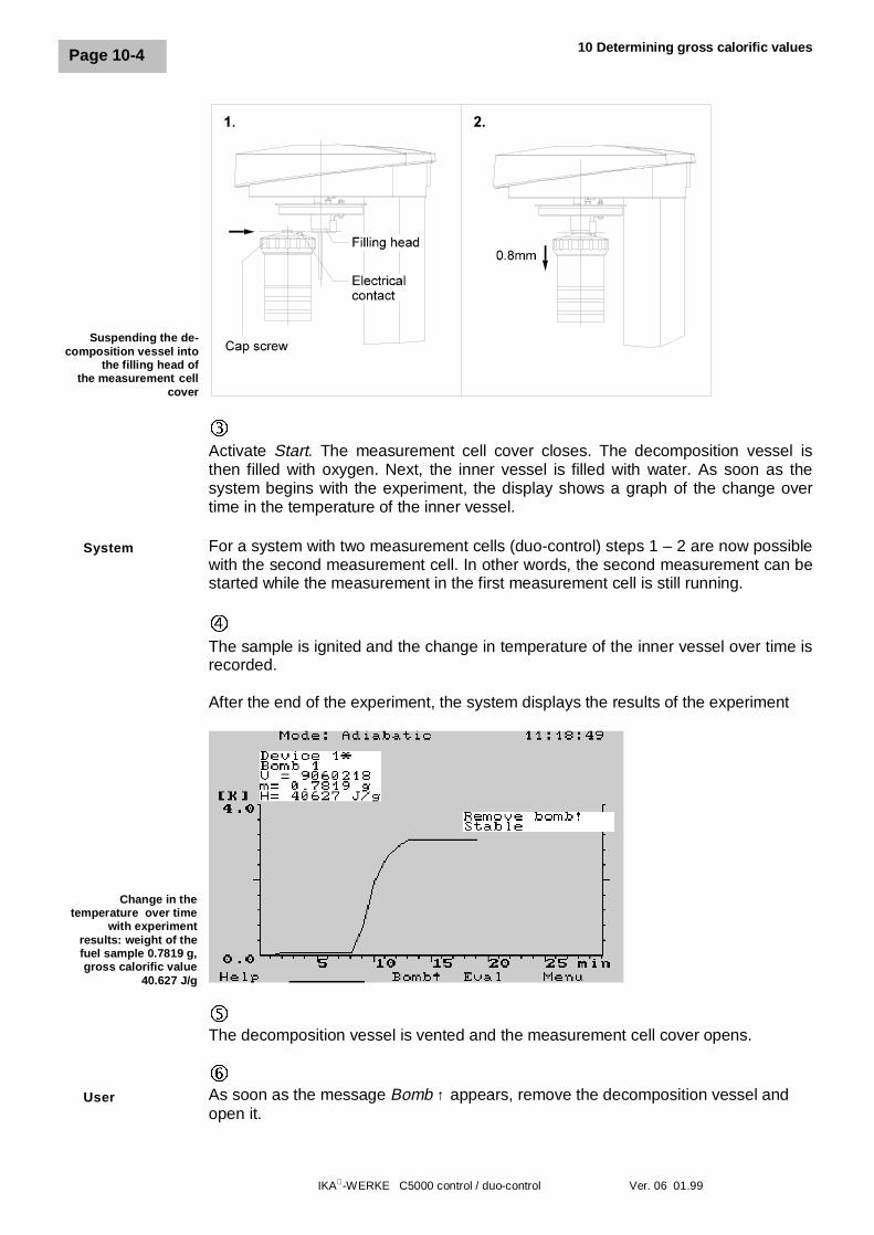
10 Determining gross calorific values
IKA-WERKE C5000 control / duo-control Ver. 06 01.99
Page 10-4
íActivate Start. The measurement cell cover closes. The decomposition vessel isthen filled with oxygen. Next, the inner vessel is filled with water. As soon as thesystem begins with the experiment, the display shows a graph of the change overtime in the temperature of the inner vessel.
For a system with two measurement cells (duo-control) steps 1 – 2 are now possiblewith the second measurement cell. In other words, the second measurement can bestarted while the measurement in the first measurement cell is still running.
÷The sample is ignited and the change in temperature of the inner vessel over time isrecorded.
After the end of the experiment, the system displays the results of the experiment
Change in thetemperature over time
with experimentresults: weight of thefuel sample 0.7819 g,gross calorific value
40.627 J/g
ûThe decomposition vessel is vented and the measurement cell cover opens.
øAs soon as the message Bomb ↑ appears, remove the decomposition vessel andopen it.
Suspending the de-composition vessel into
the filling head ofthe measurement cell
cover
System
User
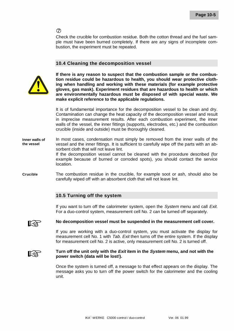
IKA-WERKE C5000 control / duo-control Ver. 06 01.99
Page 10-5
ùCheck the crucible for combustion residue. Both the cotton thread and the fuel sam-ple must have been burned completely. If there are any signs of incomplete com-bustion, the experiment must be repeated.
10.4 Cleaning the decomposition vessel
If there is any reason to suspect that the combustion sample or the combus-tion residue could be hazardous to health, you should wear protective cloth-ing when handling and working with these materials (for example protectivegloves, gas mask). Experiment residues that are hazardous to health or whichare environmentally hazardous must be disposed of with special waste. Wemake explicit reference to the applicable regulations.
It is of fundamental importance for the decomposition vessel to be clean and dry.Contamination can change the heat capacity of the decomposition vessel and resultin imprecise measurement results. After each combustion experiment, the innerwalls of the vessel, the inner fittings (supports, electrodes, etc.) and the combustioncrucible (inside and outside) must be thoroughly cleaned.
In most cases, condensation must simply be removed from the inner walls of thevessel and the inner fittings. It is sufficient to carefully wipe off the parts with an ab-sorbent cloth that will not leave lint.If the decomposition vessel cannot be cleaned with the procedure described (forexample because of burned or corroded spots), you should contact the servicelocation.
The combustion residue in the crucible, for example soot or ash, should also becarefully wiped off with an absorbent cloth that will not leave lint.
10.5 Turning off the system
If you want to turn off the calorimeter system, open the System menu and call Exit.For a duo-control system, measurement cell No. 2 can be turned off separately.
No decomposition vessel must be suspended in the measurement cell cover.
If you are working with a duo-control system, you must activate the display formeasurement cell No. 1 with Tab. Exit then turns off the entire system. If the displayfor measurement cell No. 2 is active, only measurement cell No. 2 is turned off.
Turn off the unit only with the Exit item in the System menu, and not with thepower switch (data will be lost!).
Once the system is turned off, a message to that effect appears on the display. Themessage asks you to turn off the power switch for the calorimeter and the coolingunit.
Inner walls ofthe vessel
Crucible
+
+
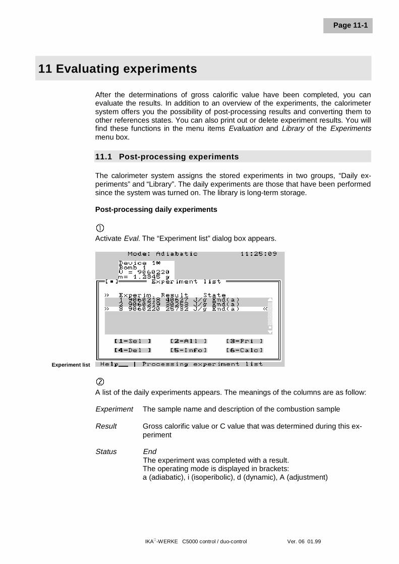
IKA-WERKE C5000 control / duo-control Ver. 06 01.99
Page 11-1
11 Evaluating experiments
After the determinations of gross calorific value have been completed, you canevaluate the results. In addition to an overview of the experiments, the calorimetersystem offers you the possibility of post-processing results and converting them toother references states. You can also print out or delete experiment results. You willfind these functions in the menu items Evaluation and Library of the Experimentsmenu box.
11.1 Post-processing experiments
The calorimeter system assigns the stored experiments in two groups, “Daily ex-periments” and “Library”. The daily experiments are those that have been performedsince the system was turned on. The library is long-term storage.
Post-processing daily experiments
� Activate Eval. The “Experiment list” dialog box appears.
Experiment list
ôA list of the daily experiments appears. The meanings of the columns are as follow:
Experiment The sample name and description of the combustion sample
Result Gross calorific value or C value that was determined during this ex-periment
Status EndThe experiment was completed with a result.The operating mode is displayed in brackets:a (adiabatic), i (isoperibolic), d (dynamic), A (adjustment)
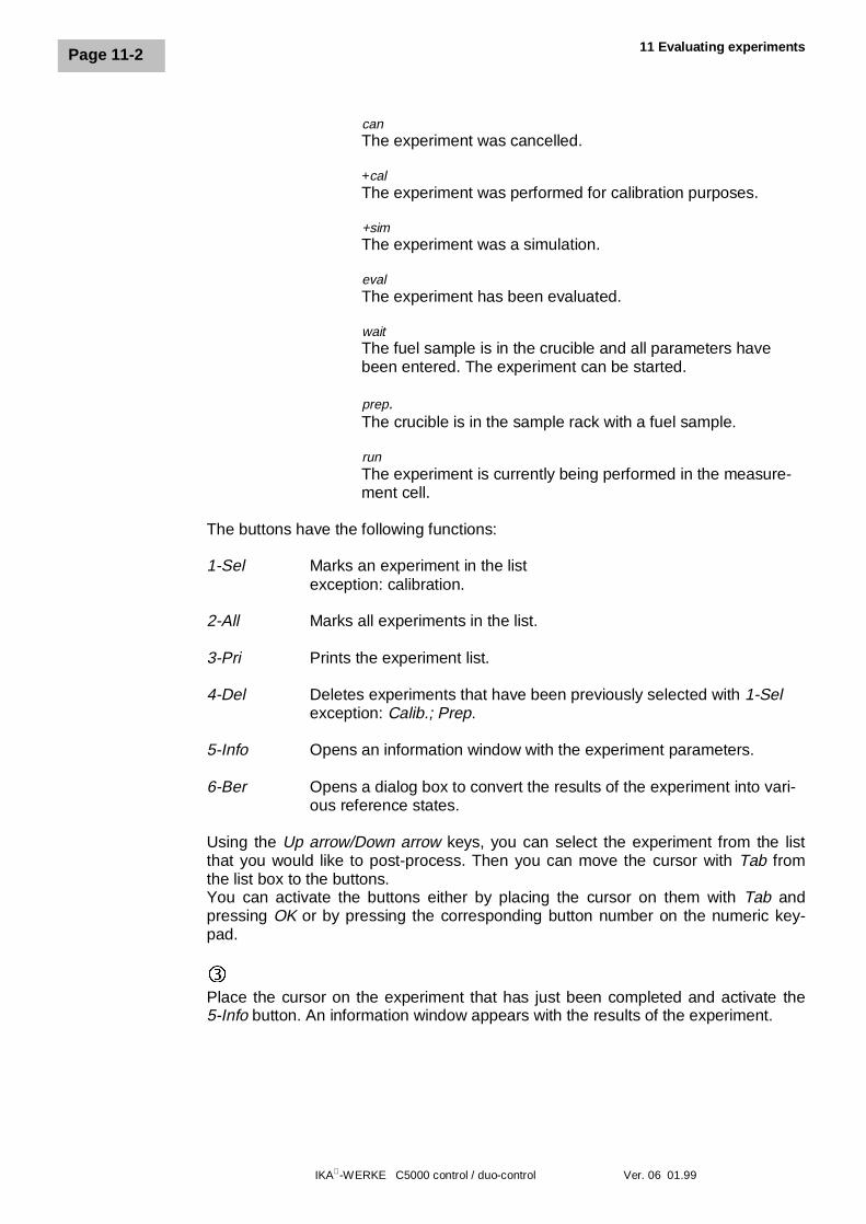
11 Evaluating experiments
IKA-WERKE C5000 control / duo-control Ver. 06 01.99
Page 11-2
canThe experiment was cancelled.
+calThe experiment was performed for calibration purposes.
+simThe experiment was a simulation.
evalThe experiment has been evaluated.
waitThe fuel sample is in the crucible and all parameters havebeen entered. The experiment can be started.
prep.The crucible is in the sample rack with a fuel sample.
runThe experiment is currently being performed in the measure-ment cell.
The buttons have the following functions:
1-Sel Marks an experiment in the listexception: calibration.
2-All Marks all experiments in the list.
3-Pri Prints the experiment list.
4-Del Deletes experiments that have been previously selected with 1-Selexception: Calib.; Prep.
5-Info Opens an information window with the experiment parameters.
6-Ber Opens a dialog box to convert the results of the experiment into vari-ous reference states.
Using the Up arrow/Down arrow keys, you can select the experiment from the listthat you would like to post-process. Then you can move the cursor with Tab fromthe list box to the buttons.You can activate the buttons either by placing the cursor on them with Tab andpressing OK or by pressing the corresponding button number on the numeric key-pad.
íPlace the cursor on the experiment that has just been completed and activate the5-Info button. An information window appears with the results of the experiment.
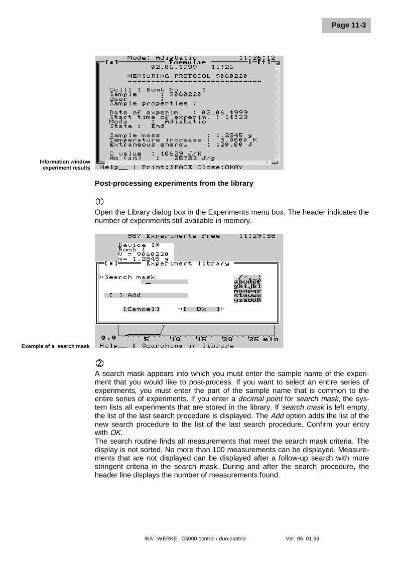
IKA-WERKE C5000 control / duo-control Ver. 06 01.99
Page 11-3
Information windowexperiment results
Post-processing experiments from the library
�Open the Library dialog box in the Experiments menu box. The header indicates thenumber of experiments still available in memory.
Example of a search mask
ôA search mask appears into which you must enter the sample name of the experi-ment that you would like to post-process. If you want to select an entire series ofexperiments, you must enter the part of the sample name that is common to theentire series of experiments. If you enter a decimal point for search mask, the sys-tem lists all experiments that are stored in the library. If search mask is left empty,the list of the last search procedure is displayed. The Add option adds the list of thenew search procedure to the list of the last search procedure. Confirm your entrywith OK.The search routine finds all measurements that meet the search mask criteria. Thedisplay is not sorted. No more than 100 measurements can be displayed. Measure-ments that are not displayed can be displayed after a follow-up search with morestringent criteria in the search mask. During and after the search procedure, theheader line displays the number of measurements found.
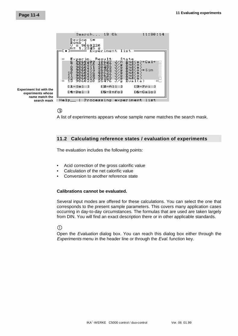
11 Evaluating experiments
IKA-WERKE C5000 control / duo-control Ver. 06 01.99
Page 11-4
Experiment list with theexperiments whose
name match thesearch mask
íA list of experiments appears whose sample name matches the search mask.
11.2 Calculating reference states / evaluation of experiments
The evaluation includes the following points:
• Acid correction of the gross calorific value• Calculation of the net calorific value• Conversion to another reference state
Calibrations cannot be evaluated.
Several input modes are offered for these calculations. You can select the one thatcorresponds to the present sample parameters. This covers many application casesoccurring in day-to-day circumstances. The formulas that are used are taken largelyfrom DIN. You will find an exact description there or in other applicable standards.
�Open the Evaluation dialog box. You can reach this dialog box either through theExperiments menu in the header line or through the Eval. function key.
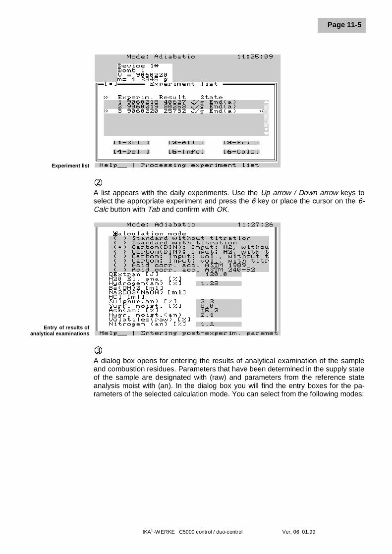
IKA-WERKE C5000 control / duo-control Ver. 06 01.99
Page 11-5
Experiment list
ôA list appears with the daily experiments. Use the Up arrow / Down arrow keys toselect the appropriate experiment and press the 6 key or place the cursor on the 6-Calc button with Tab and confirm with OK.
Entry of results ofanalytical examinations
íA dialog box opens for entering the results of analytical examination of the sampleand combustion residues. Parameters that have been determined in the supply stateof the sample are designated with (raw) and parameters from the reference stateanalysis moist with (an). In the dialog box you will find the entry boxes for the pa-rameters of the selected calculation mode. You can select from the following modes:
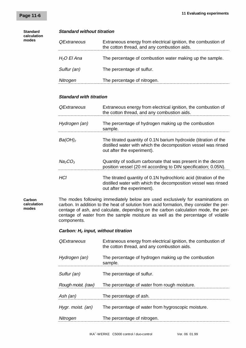
11 Evaluating experiments
IKA-WERKE C5000 control / duo-control Ver. 06 01.99
Page 11-6
Standard without titration
QExtraneous Extraneous energy from electrical ignition, the combustion ofthe cotton thread, and any combustion aids.
H2O El Ana The percentage of combustion water making up the sample.
Sulfur (an) The percentage of sulfur.
Nitrogen The percentage of nitrogen.
Standard with titration
QExtraneous Extraneous energy from electrical ignition, the combustion of the cotton thread, and any combustion aids.
Hydrogen (an) The percentage of hydrogen making up the combustion sample.
Ba(OH)2 The titrated quantity of 0.1N barium hydroxide (titration of thedistilled water with which the decomposition vessel was rinsed
out after the experiment).
Na2CO3 Quantity of sodium carbonate that was present in the decom position vessel (20 ml according to DIN specification; 0.05N).
HCl The titrated quantity of 0.1N hydrochloric acid (titration of thedistilled water with which the decomposition vessel was rinsed
out after the experiment).
The modes following immediately below are used exclusively for examinations oncarbon. In addition to the heat of solution from acid formation, they consider the per-centage of ash, and calculate, depending on the carbon calculation mode, the per-centage of water from the sample moisture as well as the percentage of volatilecomponents.
Carbon: H2 input, without titration
QExtraneous Extraneous energy from electrical ignition, the combustion of the cotton thread, and any combustion aids.
Hydrogen (an) The percentage of hydrogen making up the combustion sample.
Sulfur (an) The percentage of sulfur.
Rough moist. (raw) The percentage of water from rough moisture.
Ash (an) The percentage of ash.
Hygr. moist. (an) The percentage of water from hygroscopic moisture.
Nitrogen The percentage of nitrogen.
Standardcalculationmodes
Carboncalculationmodes
IKA-WERKE C5000 control / duo-control Ver. 06 01.99
Page 11-7
Carbon: H2 input, with titration
QExtraneous Extraneous energy from electrical ignition, the combustion of the cotton thread, and any combustion aids.
Hydrogen (an) The percentage of hydrogen making up the combustion sample.
Ba(OH)2 The titrated quantity of 0.1N barium hydroxide (titration of thedistilled water with which the decomposition vessel was rinsed
out after the experiment).
Na2CO3 Quantity of sodium carbonate that was present in the decomposition vessel (20 ml, 0.05N).
HCl The titrated quantity of 0.1N hydrochloric acid (titration of thedistilled water with which the decomposition vessel was rinsed
out after the experiment).
Rough moist. (raw) The percentage of water from rough moisture.
Ash (an) The percentage of ash.
Hygr. moist. (an) The percentage of water from hygroscopic moisture.
Carbon: Volatile input, without titration
QExtraneous Extraneous energy from electrical ignition, the combustion of the cotton thread, and any combustion aids.
Sulfur (an) The percentage of sulfur.
Rough moist. (raw) The percentage of water from rough moisture.
Ash (an) The percentage of ash.
Hygr. moist. (an) The percentage of water from hygroscopic moisture.
Volat. comp. (raw) The percentage of volatile components.
Nitrogen The percentage of nitrogen.
11 Evaluating experiments
IKA-WERKE C5000 control / duo-control Ver. 06 01.99
Page 11-8
Carbon: Volatile input, with titration
QExtraneous Extraneous energy from electrical ignition, the combustion of the cotton thread, and any combustion aids.
Volat. comp. (raw) The percentage of volatile components.
Ba(OH)2 The titrated quantity of 0.1N barium hydroxide (titration of thedistilled water with which the decomposition vessel was rinsed
out after the experiment).
Na2CO3 Quantity of sodium carbonate that was present in the decomposition vessel (20 ml, 0.05N).
HCl The titrated quantity of 0.1N hydrochloric acid (titration of thedistilled water with which the decomposition vessel was rinsed
out after the experiment).
Rough moist. (raw) The percentage of water from rough moisture.
Ash (an) The percentage of ash.
Hygr. moist. (an) The percentage of water from hygroscopic moisture.
Acid correction based on ASTM 1989
QExtraneous Extraneous energy from electrical ignition, the combustion of the cotton thread, and any combustion aids.
Hydrogen (an) The percentage of hydrogen making up the combustion sample.
Na2CO3 Titrated quantity in ml (0.34N).
Rough moist. (raw) The percentage of water from rough moisture.
Ash (an) The percentage of ash.
Hygr. moist. (an) The percentage of water from hygroscopic moisture.
Sulfur (an) The percentage of sulfur.
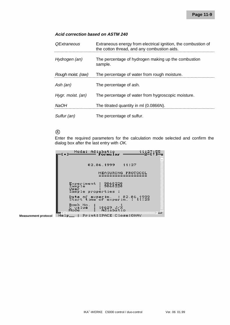
IKA-WERKE C5000 control / duo-control Ver. 06 01.99
Page 11-9
Acid correction based on ASTM 240
QExtraneous Extraneous energy from electrical ignition, the combustion of the cotton thread, and any combustion aids.
Hydrogen (an) The percentage of hydrogen making up the combustion sample.
Rough moist. (raw) The percentage of water from rough moisture.
Ash (an) The percentage of ash.
Hygr. moist. (an) The percentage of water from hygroscopic moisture.
NaOH The titrated quantity in ml (0.0866N).
Sulfur (an) The percentage of sulfur.
÷Enter the required parameters for the calculation mode selected and confirm thedialog box after the last entry with OK.
Measurement protocol
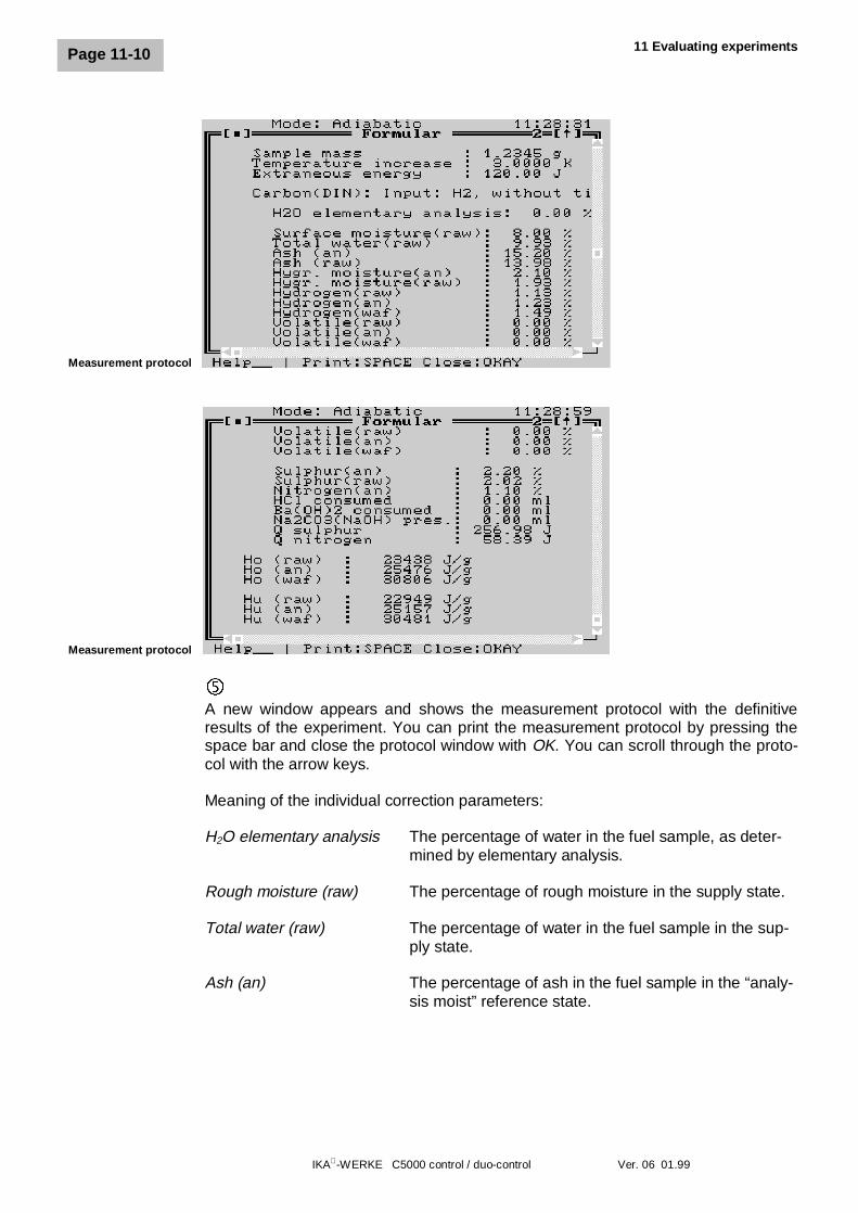
11 Evaluating experiments
IKA-WERKE C5000 control / duo-control Ver. 06 01.99
Page 11-10
Measurement protocol
Measurement protocol
ûA new window appears and shows the measurement protocol with the definitiveresults of the experiment. You can print the measurement protocol by pressing thespace bar and close the protocol window with OK. You can scroll through the proto-col with the arrow keys.
Meaning of the individual correction parameters:
H2O elementary analysis The percentage of water in the fuel sample, as deter-mined by elementary analysis.
Rough moisture (raw) The percentage of rough moisture in the supply state.
Total water (raw) The percentage of water in the fuel sample in the sup-ply state.
Ash (an) The percentage of ash in the fuel sample in the “analy-sis moist” reference state.
IKA-WERKE C5000 control / duo-control Ver. 06 01.99
Page 11-11
Ash (raw) The percentage of ash in the fuel sample in thesupply state.
Hygr. moisture (an) The percentage of hygroscopic moisture in the “analy-sis moist” reference state.
Hygr. moisture (raw) The percentage of hygroscopic moisture in thesupply state.
Hydrogen (raw) The percentage of hydrogen in the supply state.
Hydrogen (an) The percentage of hydrogen in the “analysis moist”reference state.
Hydrogen (waf) The percentage of hydrogen in the “water andash-free” reference state.
Volatiles (raw) The percentage of volatile components in thesupply state.
Volatiles (an) The percentage of volatile components in the “analysismoist” reference state.
Volatiles (waf) The percentage of volatile components in the “waterand ash-free” reference state.
Sulfur (an) The percentage of sulfur in the fuel sample in the“analysis moist” reference state.
Sulfur (raw) The percentage of sulfur in the fuel sample in thesupply state.
Nitrogen (an) The percentage of nitrogen in the fuel sample in the“analysis moist” reference state.
HCl consumed The titrated quantity of hydrochloric acid.
Ba(OH)2 consumed The titrated quantity of barium hydroxide.
Na2CO3 present The quantity of Na2CO3 present in thedecomposition vessel.
Q sulfur The heat of solution from the formation of sulfuric acid.
Q nitrogen The heat of solution from the formation of nitric acid.
Ho (raw) The specific gross calorific value of the fuel sample inthe supply state.
Ho (an) The specific gross calorific value of the fuel sample inthe “analysis moist” reference state.
Ho (waf) The specific gross calorific value of the fuel sample inthe “water and ash-free” reference state.
11 Evaluating experiments
IKA-WERKE C5000 control / duo-control Ver. 06 01.99
Page 11-12
Hu (raw) The specific net calorific value of the fuel sample in thesupply state.
Hu (an) The specific net calorific value of the fuel sample in the“analysis moist” reference state.
Hu (waf) The specific net calorific value of the fuel sample in the“water and ash-free” reference state.
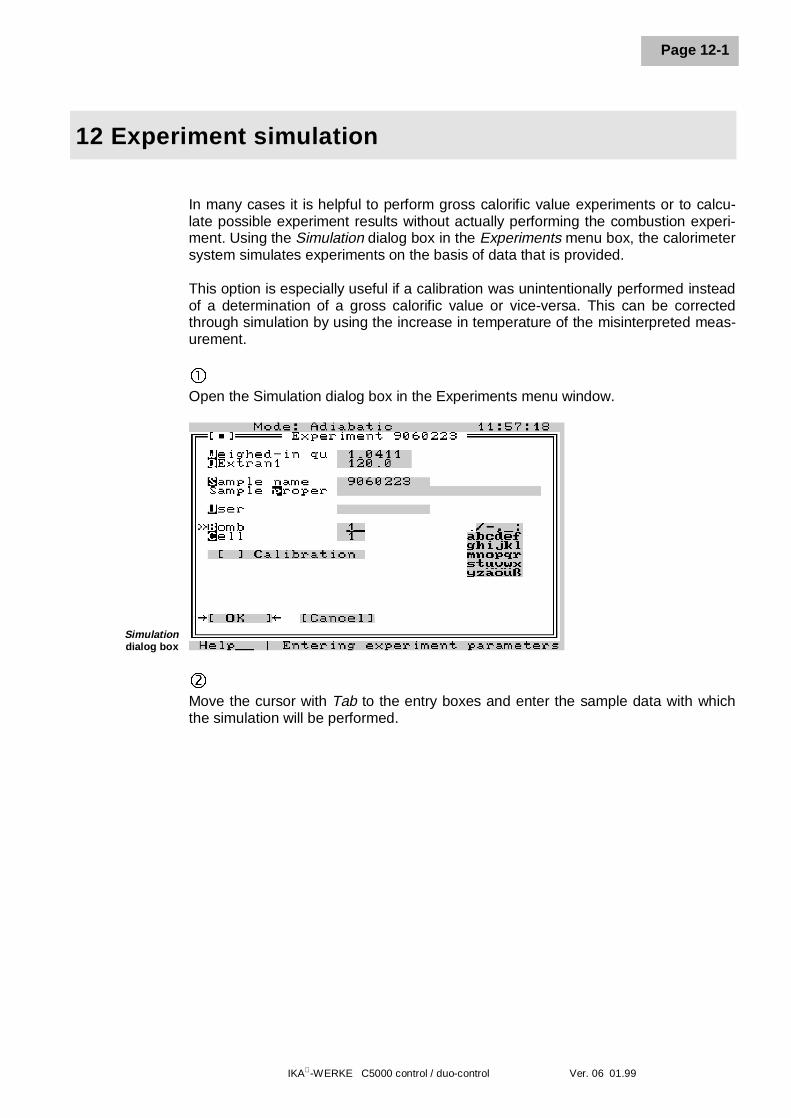
IKA-WERKE C5000 control / duo-control Ver. 06 01.99
Page 12-1
12 Experiment simulation
In many cases it is helpful to perform gross calorific value experiments or to calcu-late possible experiment results without actually performing the combustion experi-ment. Using the Simulation dialog box in the Experiments menu box, the calorimetersystem simulates experiments on the basis of data that is provided.
This option is especially useful if a calibration was unintentionally performed insteadof a determination of a gross calorific value or vice-versa. This can be correctedthrough simulation by using the increase in temperature of the misinterpreted meas-urement.
�Open the Simulation dialog box in the Experiments menu window.
Simulationdialog box
ôMove the cursor with Tab to the entry boxes and enter the sample data with whichthe simulation will be performed.
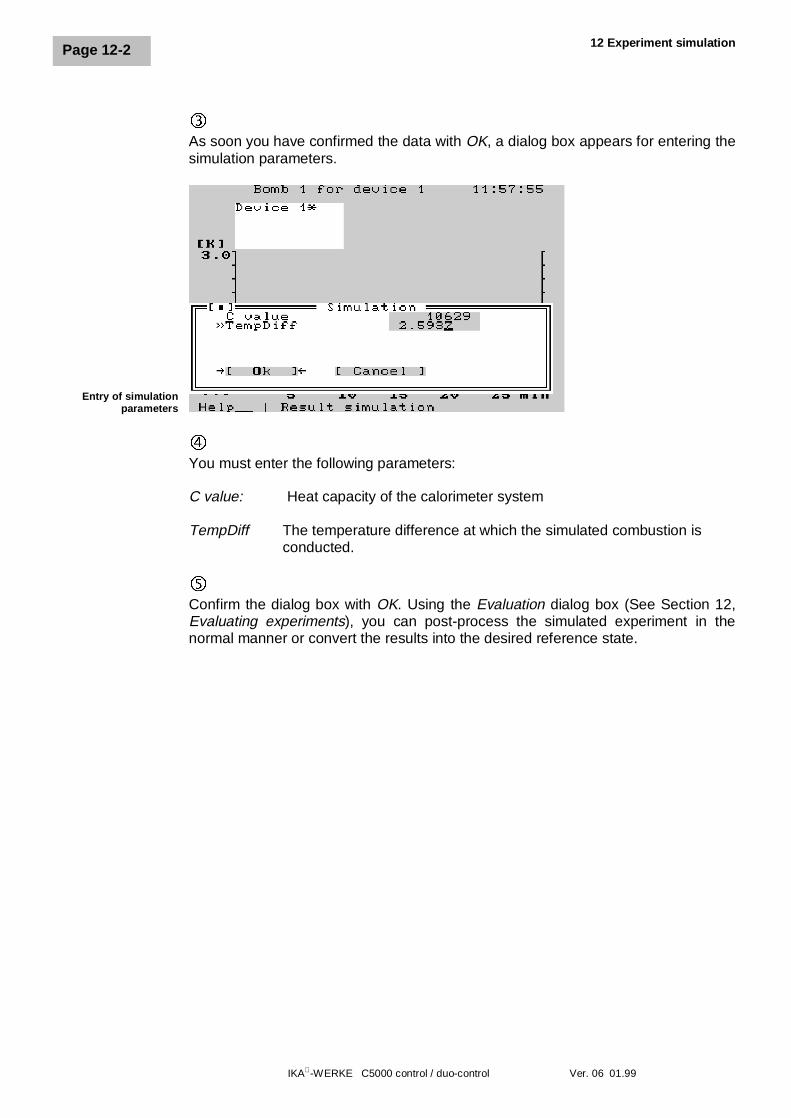
12 Experiment simulation
IKA-WERKE C5000 control / duo-control Ver. 06 01.99
Page 12-2
íAs soon you have confirmed the data with OK, a dialog box appears for entering thesimulation parameters.
Entry of simulationparameters
÷You must enter the following parameters:
C value: Heat capacity of the calorimeter system
TempDiff The temperature difference at which the simulated combustion isconducted.
ûConfirm the dialog box with OK. Using the Evaluation dialog box (See Section 12,Evaluating experiments), you can post-process the simulated experiment in thenormal manner or convert the results into the desired reference state.
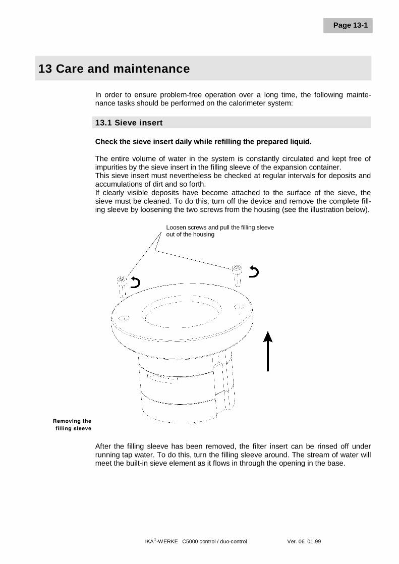
IKA-WERKE C5000 control / duo-control Ver. 06 01.99
Page 13-1
13 Care and maintenance
In order to ensure problem-free operation over a long time, the following mainte-nance tasks should be performed on the calorimeter system:
13.1 Sieve insert
Check the sieve insert daily while refilling the prepared liquid.
The entire volume of water in the system is constantly circulated and kept free ofimpurities by the sieve insert in the filling sleeve of the expansion container.This sieve insert must nevertheless be checked at regular intervals for deposits andaccumulations of dirt and so forth.If clearly visible deposits have become attached to the surface of the sieve, thesieve must be cleaned. To do this, turn off the device and remove the complete fill-ing sleeve by loosening the two screws from the housing (see the illustration below).
After the filling sleeve has been removed, the filter insert can be rinsed off underrunning tap water. To do this, turn the filling sleeve around. The stream of water willmeet the built-in sieve element as it flows in through the opening in the base.
Removing thefilling sleeve
Loosen screws and pull the filling sleeveout of the housing
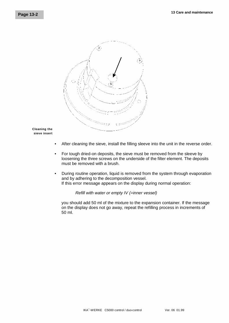
13 Care and maintenance
IKA-WERKE C5000 control / duo-control Ver. 06 01.99
Page 13-2
• After cleaning the sieve, install the filling sleeve into the unit in the reverse order.
• For tough dried-on deposits, the sieve must be removed from the sleeve byloosening the three screws on the underside of the filter element. The depositsmust be removed with a brush.
• During routine operation, liquid is removed from the system through evaporationand by adhering to the decomposition vessel.If this error message appears on the display during normal operation:
Refill with water or empty IV (=inner vessel)
you should add 50 ml of the mixture to the expansion container. If the messageon the display does not go away, repeat the refilling process in increments of50 ml.
Cleaning thesieve insert
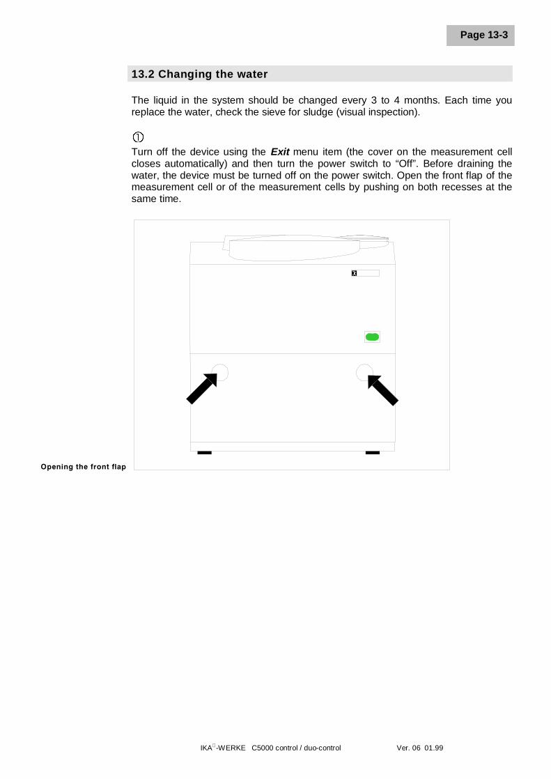
IKA-WERKE C5000 control / duo-control Ver. 06 01.99
Page 13-3
13.2 Changing the water
The liquid in the system should be changed every 3 to 4 months. Each time youreplace the water, check the sieve for sludge (visual inspection).
�Turn off the device using the Exit menu item (the cover on the measurement cellcloses automatically) and then turn the power switch to “Off”. Before draining thewater, the device must be turned off on the power switch. Open the front flap of themeasurement cell or of the measurement cells by pushing on both recesses at thesame time.
Opening the front flap
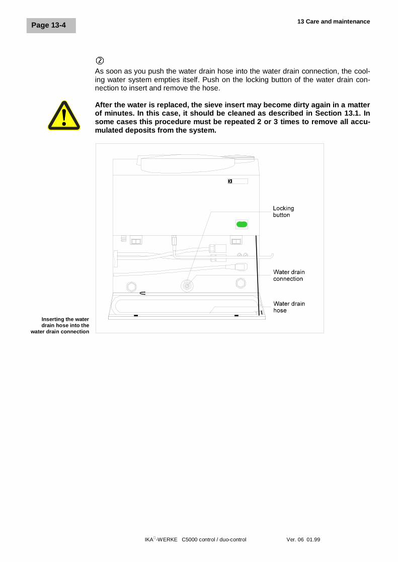
13 Care and maintenance
IKA-WERKE C5000 control / duo-control Ver. 06 01.99
Page 13-4
ôAs soon as you push the water drain hose into the water drain connection, the cool-ing water system empties itself. Push on the locking button of the water drain con-nection to insert and remove the hose.
After the water is replaced, the sieve insert may become dirty again in a matterof minutes. In this case, it should be cleaned as described in Section 13.1. Insome cases this procedure must be repeated 2 or 3 times to remove all accu-mulated deposits from the system.
Inserting the waterdrain hose into the
water drain connection
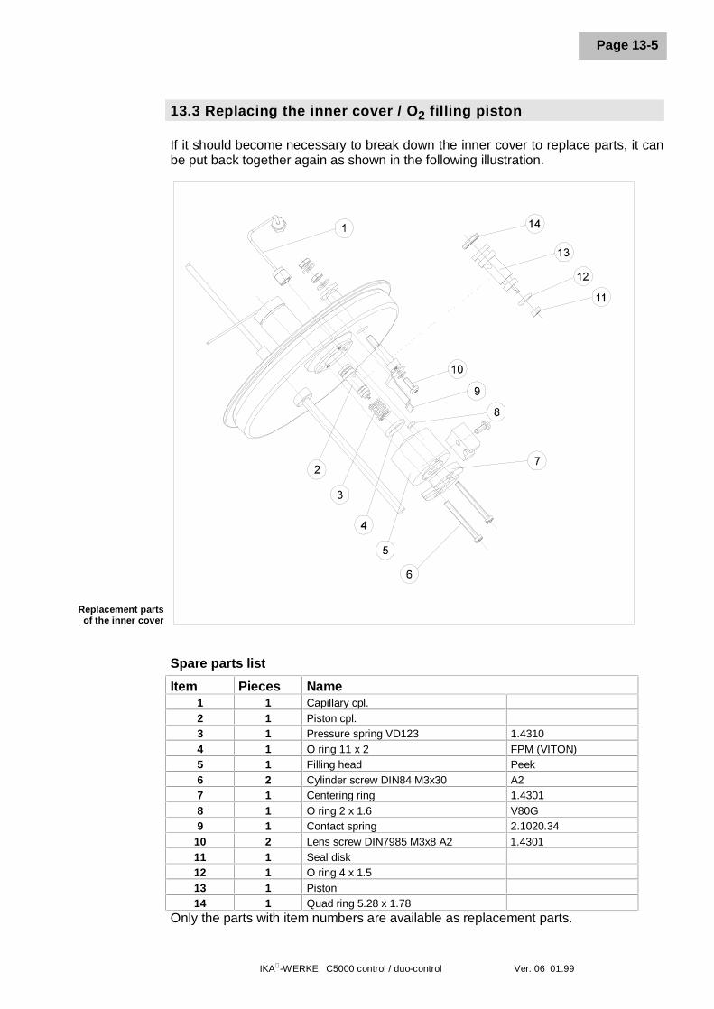
IKA-WERKE C5000 control / duo-control Ver. 06 01.99
Page 13-5
13.3 Replacing the inner cover / O2 filling piston
If it should become necessary to break down the inner cover to replace parts, it canbe put back together again as shown in the following illustration.
Spare parts list
Item Pieces Name1 1 Capillary cpl.2 1 Piston cpl.3 1 Pressure spring VD123 1.43104 1 O ring 11 x 2 FPM (VITON)5 1 Filling head Peek6 2 Cylinder screw DIN84 M3x30 A27 1 Centering ring 1.43018 1 O ring 2 x 1.6 V80G9 1 Contact spring 2.1020.34
10 2 Lens screw DIN7985 M3x8 A2 1.430111 1 Seal disk12 1 O ring 4 x 1.513 1 Piston14 1 Quad ring 5.28 x 1.78
Only the parts with item numbers are available as replacement parts.
Replacement partsof the inner cover
13 Care and maintenance
IKA-WERKE C5000 control / duo-control Ver. 06 01.99
Page 13-6
If it should become necessary to replace the O2 filling piston (item 2), proceed asfollows:
�Loosen the screws (item6) with a blade-screwdriver.
ôRemove the centering ring (item 7) together with the filling head (item 5), the pres-sure spring (item 3) and the piston (item 2)
Caution: The seals (item 4 and item 8) are free
íPush the pressure spring (item 3) onto the new piston and insert both parts into thefilling head. The remainder of the assembly takes place in the opposite order.
Caution: During reassembly, make certain the filling head is in thecorrect position (item 5). The seals (item 4 and item 8) shouldbe aligned on the opposite side of the inner cover.
After replacing the piston and the seal disks, the decomposition vessel mustbe refilled with oxygen using the maintenance menu (menu items O2 fill / de-pressurize) and then depressurized in order to test the complete unit forproper seal.
13.4 Replacing the O2 seal
• If a leak is detected while filling the decomposition vessel with oxygen, the O2
seal on the filling piston must be replaced:
- Remove the decomposition vessel from the measurement cell.- Activate the O2 seal menu item from the Maintenance menu to extend the piston.- Remove the small orange seal from the extended piston (see Section 13.3, item 11).- Insert the new seal (included with delivery) onto the piston.- Activate the O2 seal menu item from the Maintenance menu again to retract the piston again.
13.5 Decomposition vessels
For maintenance of the decomposition vessel, please read the C5010/5012 Oper-ating Instructions.
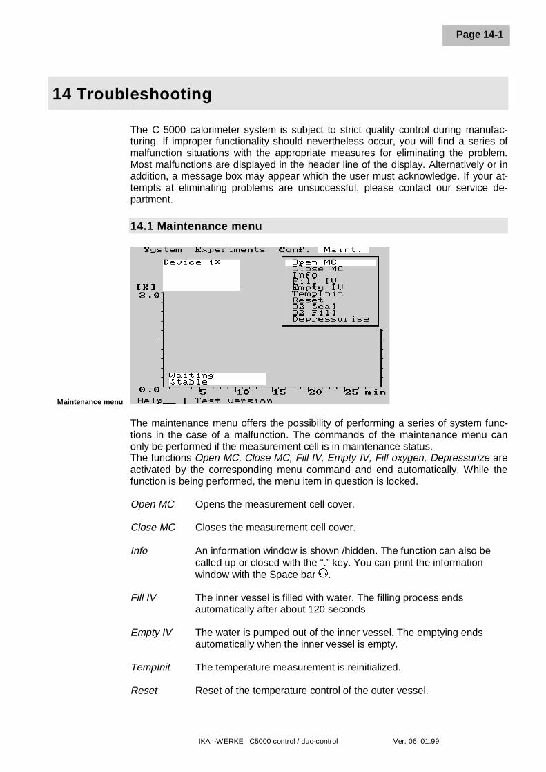
IKA-WERKE C5000 control / duo-control Ver. 06 01.99
Page 14-1
14 Troubleshooting
The C 5000 calorimeter system is subject to strict quality control during manufac-turing. If improper functionality should nevertheless occur, you will find a series ofmalfunction situations with the appropriate measures for eliminating the problem.Most malfunctions are displayed in the header line of the display. Alternatively or inaddition, a message box may appear which the user must acknowledge. If your at-tempts at eliminating problems are unsuccessful, please contact our service de-partment.
14.1 Maintenance menu
Maintenance menu
The maintenance menu offers the possibility of performing a series of system func-tions in the case of a malfunction. The commands of the maintenance menu canonly be performed if the measurement cell is in maintenance status.The functions Open MC, Close MC, Fill IV, Empty IV, Fill oxygen, Depressurize areactivated by the corresponding menu command and end automatically. While thefunction is being performed, the menu item in question is locked.
Open MC Opens the measurement cell cover.
Close MC Closes the measurement cell cover.
Info An information window is shown /hidden. The function can also becalled up or closed with the “.” key. You can print the informationwindow with the Space bar .
Fill IV The inner vessel is filled with water. The filling process endsautomatically after about 120 seconds.
Empty IV The water is pumped out of the inner vessel. The emptying endsautomatically when the inner vessel is empty.
TempInit The temperature measurement is reinitialized.
Reset Reset of the temperature control of the outer vessel.
14 Troubleshooting
IKA-WERKE C5000 control / duo-control Ver. 06 01.99
Page 14-2
O2 seal The piston on the oxygen filling unit in the measurement cell cover isextended and then retracted again when it is activated a second time.
Fill O2 A decomposition vessel that is suspended in the measurement cellcover is filled with oxygen. The process ends after about 50 seconds.The process is displayed in the process window. During this proce-dure, the decomposition vessel cannot be removed.
Depressurize Over-pressure is drained from a decomposition vessel that issuspended into the measurement cell cover. The procedure endsautomatically after about 70 seconds. During this procedure, the de-composition vessel cannot be removed. The process is displayed inthe process window.
14.2 Malfunction situations
Malfunction situations with the associated message on the display:
l The coding on the decomposition vessel is not recognized:
Messages on the display:- Bomb “x” not for cell “y” (duo control)- No assignment possible- Bomb “x” is already assigned- Bomb not recognizedThe system displays the malfunction and interrupts the measurement. Check thecoding ring on the decomposition vessel and the optical detection unit on themeasurement cell for dirt or precipitates. Check the correct assignment of the de-composition vessel to the measurement cell. To continue your measurement se-ries, you may have to turn off detection of decomposition vessels (Conf. /Settings / Bombs ID). Contact the service department.
l The measurement cell cover does not open or close completely:
Messages on the display:- Cover is not closed / openThe system displays the malfunction and interrupts the measurement. Try toopen the measurement cell cover manually and close it again. To do this, exe-cute the commands Close MC and Open MC in the Maintenance menu. If thefunction cannot be restored again, please contact the service department.
IKA-WERKE C5000 control / duo-control Ver. 06 01.99
Page 14-3
l Full status of the inner vessel is not achieved within 200 seconds:
Messages on the display:- Water filling time exceededThe system displays the malfunction and interrupts the measurement. Repeat theattempt.If the error appears again, please contact the service department.
l No increase in temperature after electrical ignition:
Messages on the display:- No increase in temperatureThe system displays the malfunction and interrupts the measurement. Check theignition wire, the cotton thread, the fuel sample and the O2 supply. It may be thatyou will have to use a combustion aid.
l The combustion experiment lasts too long:
Messages on the display:- Preliminary experiment > 13 minutes- Main experiment > 16 minutesAdiabatic and isoperibolic measurements are interrupted after 13 minutes in thepreliminary experiment (warm-up) and 16 minutes in the main experiment. Checkthe stirrer drive (rotating stirring rod after the inner vessel has been emptied), theseal of the decomposition vessel (see C5010 / C5012 Operating Instructions), thefunction of the cooling unit as indicated by heat escaping from the cooler fans.
l Error while recording temperature:
Messages on the display:- Error temp. meas.The malfunction is displayed in the header line of the display. An acoustic signalis heard at the same time. The temperature display stops changing. You can tryto eliminate the error with the Temp-init. command in the Maintenance menu. Ifthis does not work, the calorimeter must be restarted.
l Water sensor error:
Messages on the display:- Water sensor errorPlease contact your service department.
14 Troubleshooting
IKA-WERKE C5000 control / duo-control Ver. 06 01.99
Page 14-4
l Problem with ignition wire:
Messages on the display:- Problem with ignition wireThis error message is displayed if the ignition capability can no longer be ensuredduring the measurement. The experiment is interrupted. Check the ignition wire,the ignition wire fastening and the contact spring on the filling head of the innercover.
l Sample rack invalid:
Messages on the display:- Sample rack invalidFor more information on this message, see the Operating Instructions for theC5020 sample rack.
l Temperature control of the system unstable:
Messages on the display:- “Unstable” statusThe “unstable” condition may last up to 10 minutes after turning on the machine,and up to 5 minutes between measurements. If this time is exceeded signifi-cantly, or if the “stable” condition is no longer reached at all, select the Reset op-tion from the maintenance menu.Check in addition the functionality of the cooler (make sure hot air is coming outof the outlet). If the “Stable” status is not reached within an additional 30 minutes,turn the machine off. If the problem persists after the unit has been turned backon again, please contact your service department.
l Memory is too low:
Messages on the display:- Memory is too lowThe total number of all measurements that the C5000 can manage during a runsequence is limited to about 240. This limitation is reached as early as after 50hours of continuous operation (25 hours with the duo-control), and the messageabove appears. The machine should then be turned off. This number has nothingto do with the storage capacity of the library.
A malfunction situation without a direct message on the display:
l Loss of power, controller in an undefined state:If no measurement was running, the system can be restarted by turning it off andback on again. If the system was in the process of performing a measurement,proceed as follows:
1. Turn the system off and back on, and start normally.2. If there is residue in the inner vessel, confirm Empty IV.3. Open the Maintenance menu4. Bleed the over-pressure from the decomposition vessel with “Depressurize”
IKA-WERKE C5000 control / duo-control Ver. 06 01.99
Page 14-5
l O2 filling does not work:
Check the O2 supply to the unit (30 bar). If there is a detectable loss of seal dur-ing the filling procedure, replace the O2 seal (see Section 13, Care and mainte-nance).
l O2 ventilation does not work:
Check the O2 supply to the unit (30 bar). Check the way the ventilation hose isinstalled and laid out. There must be no kinks or obstructions in the degassinghose. Check the settings in the Config., Settings menu. The Decomposition itemmust not be set, since this turns off O2 ventilation.
l Incomplete combustion:
Check the O2 supply to the unit (30 bar). Use a combustion aid if necessary (seealso the applicable standards under ”Taking samples/sample preparation”.
l Cover cannot be removed from the decomposition vessel:
The O2 filling / ventilation procedure is still running (see the status window in thedisplay).
l When suspending the decomposition vessel into the measurement cell, thedisplay Bomb ↓ is not changed to START:
Check the following items:
- “Stable” state not yet achieved (see status window).- The decomposition vessel was not removed when an experiment was interrupted.- No experiment is prepared.- The maintenance menu is open.- Problem with the contact spring.- Ignition wire is defective.
14.3 Performing an adjustment (adiabatic mode)
If the unit is going to be operated in adiabatic mode, an adjustment is required first.This has already been performed at the factory during the functional test. Undernormal laboratory conditions, the user must perform an adjustment again if:
- Measurement times for adiabatic measurements regularly take longer than25 minutes.
- Adiabatic measurements are frequently interrupted because the time limit for thepreliminary or the main experiment has been exceeded.
14 Troubleshooting
IKA-WERKE C5000 control / duo-control Ver. 06 01.99
Page 14-6
Procedure for an adjustment:
- Set the operating mode to “Adjustment” (see Section 8; Item 8.8 Systemsettings). For a duo-control unit, this setting refers to both measurement cells.
- Prepare a mock measurement (see Section 10, Item 10.3). An empty crucible isused. Enter the fictitious value “1” for the weighed in quantity.
- Start the measurement.
- The process completes itself automatically within 72 to 120 minutes. Uponcompletion, a value D = ….. is displayed in the result window. You should makenote of this value in your device materials. In this case the adjustment was suc-cessful.
Then switch back to the desired operating mode. If you would like to work in adia-batic mode, the calibrations must be repeated for all decomposition vessels.
If the adjustment is not successful within 120 minutes, the procedure is interruptedwithout any result.
In this case, please contact your service department.

IKA-WERKE C5000 control / duo-control Ver. 06 01.99
Page 15-1
15 Accessories and Consumables
Description of part ID No.
Accessories
C 5010 IKA Decomposition vessel 7114000
C 5012 IKA Decomposition vessel 7174200
C 5010.4 Attachment for combustible crucible 3016900
C 5010.5 Attachment for large crucible 3055900
C 5020 Sample rack 7145000
Ventilation station C 5030 7198000
C 21 Pelleting press 1605300
C 29 Reduction valve 0750200
C 30 Oxygen purifier 0750300
C 44 Standard sheet DIN 51900, German 0750800
C 44 E Standard sheet DIN 51900, English 2103500
LX 300 EPSON printer (230 V, 50/60 Hz) 7000100
LX 300 EPSON printer (115 V, 50/60 Hz) 7000101
SBC 31 Analytical scale (230 V, 50/60 Hz) 7064900
SBC 31 Analytical scale (115 V, 50/60 Hz) 7064901
BP 61 Sartorius analytical scale,compl. (230 V, 50/60 Hz) 7062000
BP 61 Sartorius analytical scale,compl. (115 V, 50/60 Hz) 7062001
AC 121 S Sartorius analytical scale,compl. (230 V, 50/60 Hz) 7062200
AC 121 S Sartorius analytical scale,compl. (115 V, 50/60 Hz) 7062201
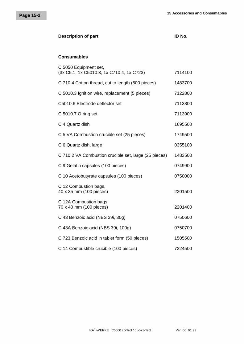
15 Accessories and Consumables
IKA-WERKE C5000 control / duo-control Ver. 06 01.99
Page 15-2
Description of part ID No.
Consumables
C 5050 Equipment set,(3x C5.1, 1x C5010.3, 1x C710.4, 1x C723) 7114100
C 710.4 Cotton thread, cut to length (500 pieces) 1483700
C 5010.3 Ignition wire, replacement (5 pieces) 7122800
C5010.6 Electrode deflector set 7113800
C 5010.7 O ring set 7113900
C 4 Quartz dish 1695500
C 5 VA Combustion crucible set (25 pieces) 1749500
C 6 Quartz dish, large 0355100
C 710.2 VA Combustion crucible set, large (25 pieces) 1483500
C 9 Gelatin capsules (100 pieces) 0749900
C 10 Acetobutyrate capsules (100 pieces) 0750000
C 12 Combustion bags,40 x 35 mm (100 pieces) 2201500
C 12A Combustion bags70 x 40 mm (100 pieces) 2201400
C 43 Benzoic acid (NBS 39i, 30g) 0750600
C 43A Benzoic acid (NBS 39i, 100g) 0750700
C 723 Benzoic acid in tablet form (50 pieces) 1505500
C 14 Combustible crucible (100 pieces) 7224500
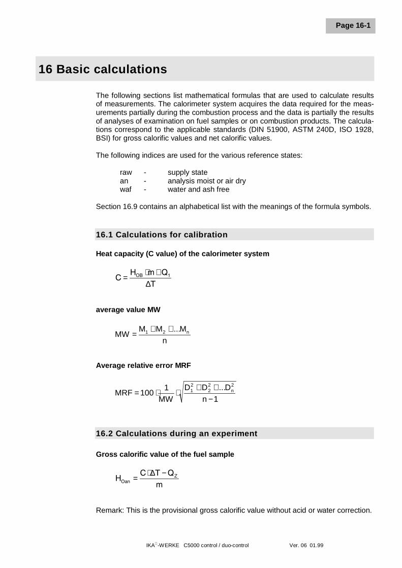
IKA-WERKE C5000 control / duo-control Ver. 06 01.99
Page 16-1
16 Basic calculations
The following sections list mathematical formulas that are used to calculate resultsof measurements. The calorimeter system acquires the data required for the meas-urements partially during the combustion process and the data is partially the resultsof analyses of examination on fuel samples or on combustion products. The calcula-tions correspond to the applicable standards (DIN 51900, ASTM 240D, ISO 1928,BSI) for gross calorific values and net calorific values.
The following indices are used for the various reference states:
raw - supply statean - analysis moist or air drywaf - water and ash free
Section 16.9 contains an alphabetical list with the meanings of the formula symbols.
16.1 Calculations for calibration
Heat capacity (C value) of the calorimeter system
average value MW
Average relative error MRF
16.2 Calculations during an experiment
Gross calorific value of the fuel sample
Remark: This is the provisional gross calorific value without acid or water correction.
C =⋅ +H m Q
TOB 1
∆
nM...MM
MW n21 ++=
1nD...DD
MW1
100MRF 2n
22
21
−++
⋅⋅=
HOanZC T Q
m=
⋅ −∆
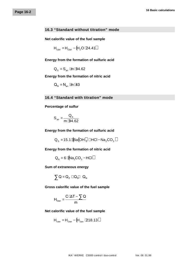
16 Basic calculations
IKA-WERKE C5000 control / duo-control Ver. 06 01.99
Page 16-2
16.3 “Standard without titration” mode
Net calorific value of the fuel sample
Energy from the formation of sulfuric acid
Energy from the formation of nitric acid
16.4 “Standard with titration” mode
Percentage of sulfur
Energy from the formation of sulfuric acid
Energy from the formation of nitric acid
( )HClCONa6Q 32N −⋅=
Sum of extraneous energy
Gross calorific value of the fuel sample
Net calorific value of the fuel sample
( )41.24OHHH 2OanUan ⋅−=
62.94mSQ anS ⋅⋅=
QN anN m= ⋅ ⋅43
62.94mQ
S San ⋅
=
Q∑ = + +Q Q QZ S N
HOan
C T Q
m=
⋅ − ∑∆
( )13.218HHH an2OanUan ⋅−=
( )( )322S CONaHClOHBa1.15Q −+⋅=
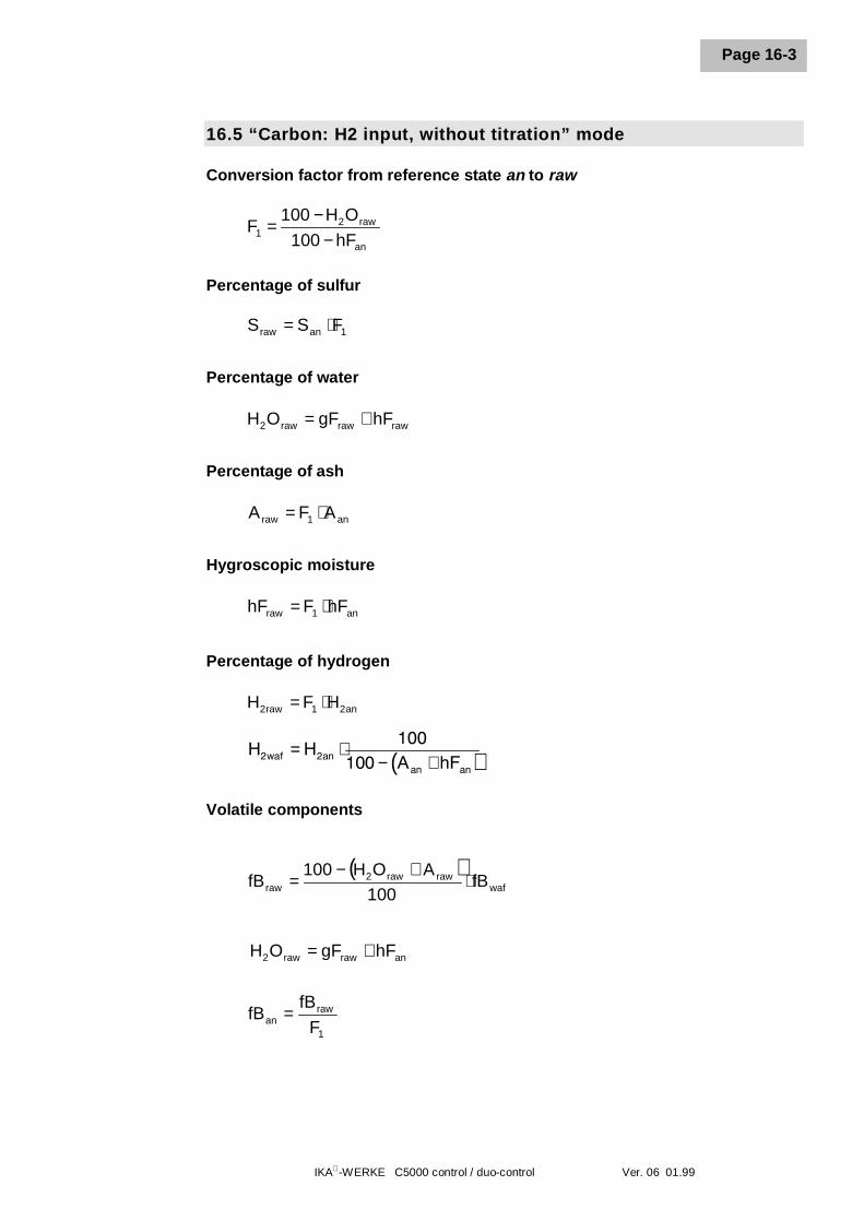
IKA-WERKE C5000 control / duo-control Ver. 06 01.99
Page 16-3
16.5 “Carbon: H2 input, without titration” mode
Conversion factor from reference state an to raw
Percentage of sulfur
Percentage of water
Percentage of ash
Hygroscopic moisture
Percentage of hydrogen
Volatile components
1
rawan F
fBfB =
an
raw21 hF100
OH100F
−−
=
1anraw FSS ⋅=
rawrawraw2 hFgFOH +=
an1raw AFA ⋅=
an1raw hFFhF ⋅=
an21raw2 HFH ⋅=
( ) H2 2
100100waf an
an an
HA hF
= ⋅− +
( )waf
rawraw2raw fB
100AOH100
fB ⋅+−
=
anrawraw2 hFgFOH +=
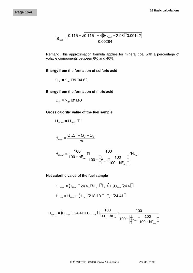
16 Basic calculations
IKA-WERKE C5000 control / duo-control Ver. 06 01.99
Page 16-4
Remark: This approximation formula applies for mineral coal with a percentage ofvolatile components between 6% and 40%.
Energy from the formation of sulfuric acid
Energy from the formation of nitric acid
Gross calorific value of the fuel sample
1FHH OanOraw ⋅=
Net calorific value of the fuel sample
( )[ ]00284.0
00142.098.2H4115.0115.0fB waf2
2
waf
⋅−−−=
62.94mSQ anS ⋅⋅=
QN anN m= ⋅ ⋅43
HOanZ SC T Q Q
m=
⋅ − −∆
HOwafan
anan
OanhFA
hF
H=−
⋅− ⋅
−
⋅100100
100
100100
100
( ) ( )41.24OHFhF41.24HH raw21anUanUraw ⋅−⋅⋅+=
( )41.24hF13.218HHH anan2OanUan ⋅+⋅−=
( )
−
⋅−⋅
−⋅⋅+=
anan
anraw2OrawUwaf
hF100100
A100
100hF100
100OH41.24HH
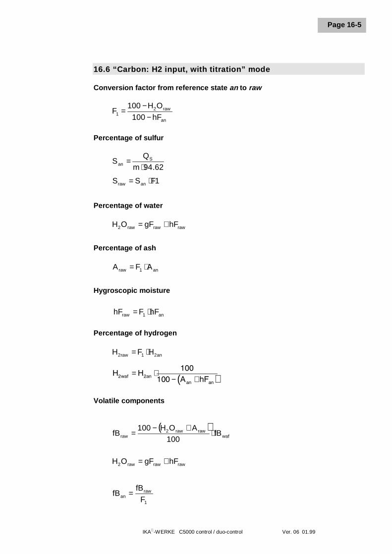
IKA-WERKE C5000 control / duo-control Ver. 06 01.99
Page 16-5
16.6 “Carbon: H2 input, with titration” mode
Conversion factor from reference state an to raw
Percentage of sulfur
Percentage of water
Percentage of ash
Hygroscopic moisture
Percentage of hydrogen
Volatile components
1
rawan F
fBfB =
an
raw21 hF100
OH100F
−−
=
62.94mQ
S San ⋅
=
1FSS anraw ⋅=
rawrawraw2 hFgFOH +=
an1raw AFA ⋅=
an1raw hFFhF ⋅=
an21raw2 HFH ⋅=
( ) H2 2
100100waf an
an an
HA hF
= ⋅− +
( )waf
rawraw2raw fB
100AOH100
fB ⋅+−
=
rawrawraw2 hFgFOH +=
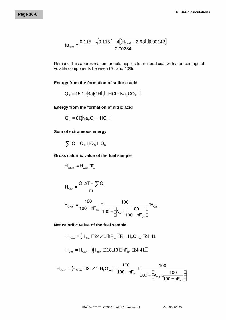
16 Basic calculations
IKA-WERKE C5000 control / duo-control Ver. 06 01.99
Page 16-6
Remark: This approximation formula applies for mineral coal with a percentage ofvolatile components between 6% and 40%.
Energy from the formation of sulfuric acid
Energy from the formation of nitric acid
Sum of extraneous energy
Gross calorific value of the fuel sample
1OanOraw FHH ⋅=
Net calorific value of the fuel sample
( )[ ]00284.0
00142.098.2H4115.0115.0fB waf2
2
waf
⋅−−−=
( )( )322S CONaHClOHBa1.15Q −+⋅=
( ) QN Na O HCl= ⋅ −6 2 3
Q Q Q QZ S N∑ = + +
HOan
C T Q
m=
⋅ − ∑∆
HOwafan
anan
OanhFA
hF
H=−
⋅− ⋅
−
⋅100
100100
100100
100
( ) 41.24OHFhF41.24HH raw21anUanUraw ⋅−⋅⋅+=
( )41.24hF13.218HHH anan2OanUan ⋅+⋅−=
( )
−
⋅−⋅
−⋅⋅+=
anan
anraw2OrawUwaf
hF100100
A100
100hF100
100OH41.24HH
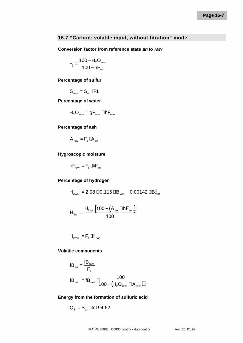
IKA-WERKE C5000 control / duo-control Ver. 06 01.99
Page 16-7
16.7 “Carbon: volatile input, without titration” mode
Conversion factor from reference state an to raw
Percentage of sulfur
Percentage of water
Percentage of ash
Hygroscopic moisture
Percentage of hydrogen
Volatile components
Energy from the formation of sulfuric acid
an
raw21 hF100
OH100F
−−
=
1FSS anraw ⋅=
rawrawraw2 hFgFOH +=
an1raw AFA ⋅=
an1raw hFFhF ⋅=
2wafwafwaf2 fB00142.0fB115.098.2H ⋅−⋅+=
( )[ ] H2
2 100
100anwaf an anH A hF
=− +
an21raw2 HFH ⋅=
1
rawan F
fBfB =
( )rawraw2rawwaf AOH100
100fBfB
+−⋅=
62.94mSQ anS ⋅⋅=
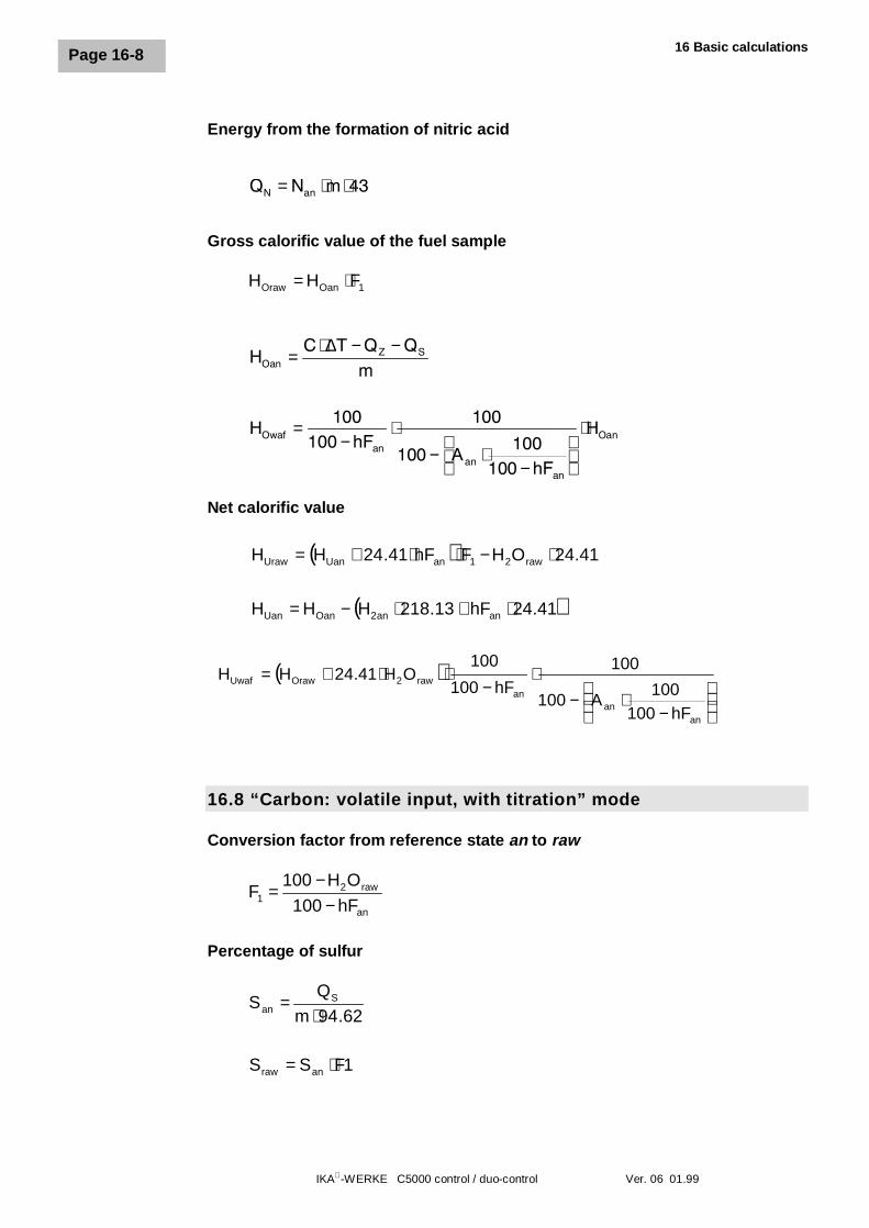
16 Basic calculations
IKA-WERKE C5000 control / duo-control Ver. 06 01.99
Page 16-8
Energy from the formation of nitric acid
Gross calorific value of the fuel sample
1OanOraw FHH ⋅=
Net calorific value
16.8 “Carbon: volatile input, with titration” mode
Conversion factor from reference state an to raw
Percentage of sulfur
QN anN m= ⋅ ⋅43
HOanZ SC T Q Q
m=
⋅ − −∆
HOwafan
anan
OanhFA
hF
H=−
⋅− ⋅
−
⋅100100
100
100100
100
( ) 41.24OHFhF41.24HH raw21anUanUraw ⋅−⋅⋅+=
( )41.24hF13.218HHH anan2OanUan ⋅+⋅−=
( )
−
⋅−⋅
−⋅⋅+=
anan
anraw2OrawUwaf
hF100100
A100
100hF100
100OH41.24HH
an
raw21 hF100
OH100F
−−
=
62.94mQ
S San ⋅
=
1FSS anraw ⋅=
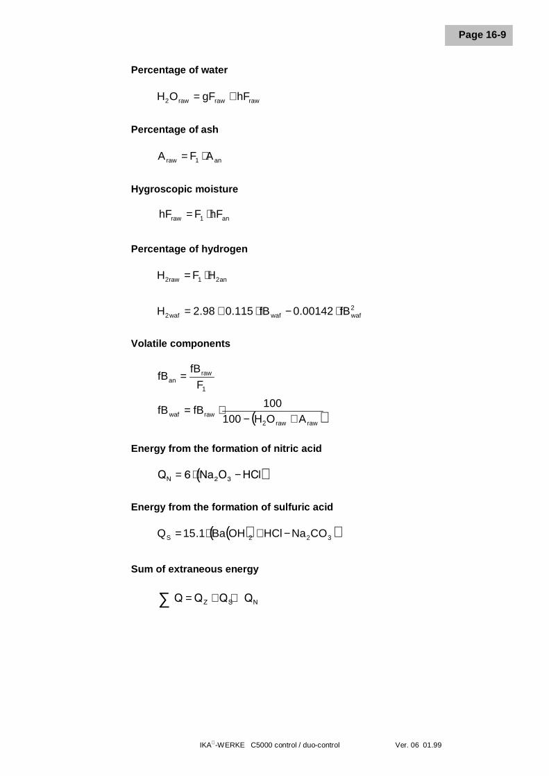
IKA-WERKE C5000 control / duo-control Ver. 06 01.99
Page 16-9
Percentage of water
Percentage of ash
Hygroscopic moisture
Percentage of hydrogen
Volatile components
Energy from the formation of nitric acid
Energy from the formation of sulfuric acid
Sum of extraneous energy
rawrawraw2 hFgFOH +=
an1raw AFA ⋅=
an1raw hFFhF ⋅=
an21raw2 HFH ⋅=
2wafwafwaf2 fB00142.0fB115.098.2H ⋅−⋅+=
1
rawan F
fBfB =
( )rawraw2rawwaf AOH100
100fBfB
+−⋅=
( ) QN Na O HCl= ⋅ −6 2 3
( )( )322S CONaHClOHBa1.15Q −+⋅=
Q Q Q QZ S N∑ = + +
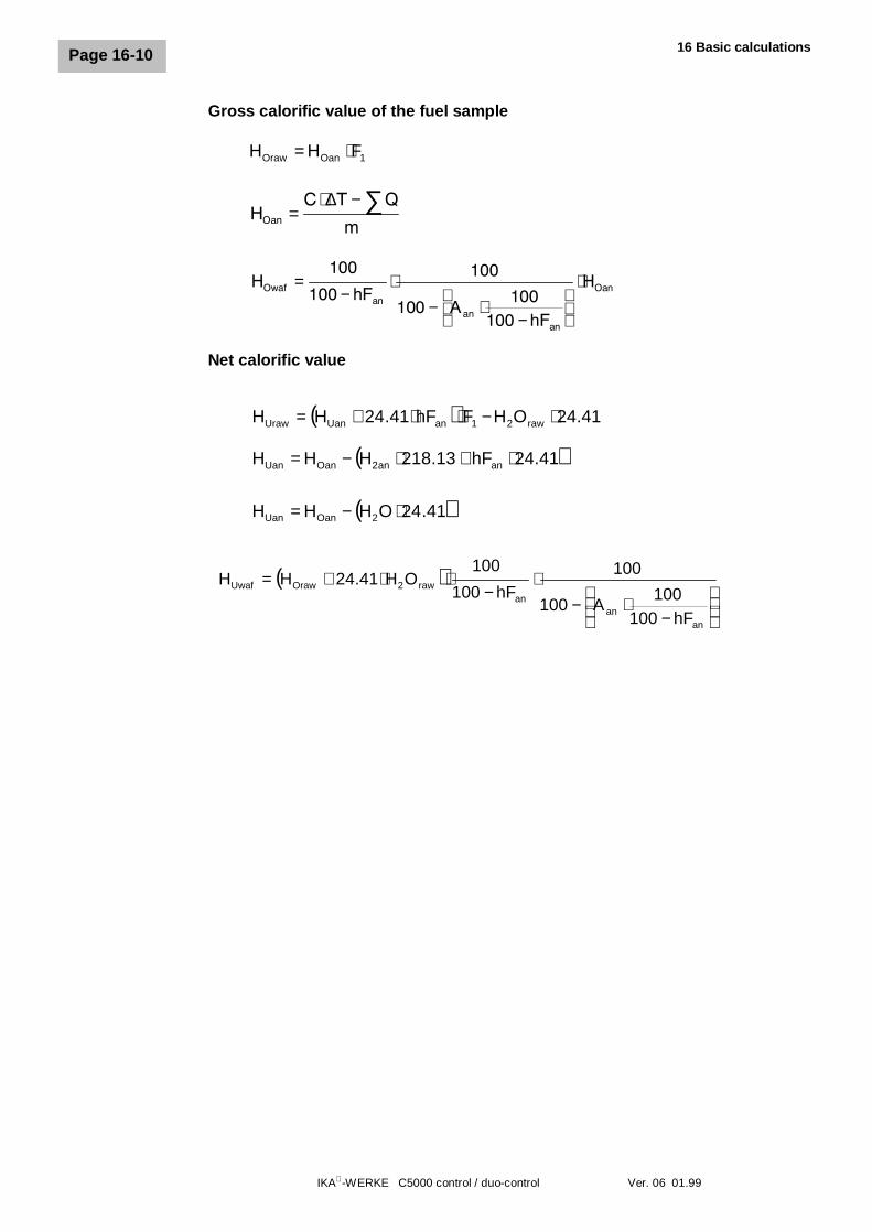
16 Basic calculations
IKA-WERKE C5000 control / duo-control Ver. 06 01.99
Page 16-10
Gross calorific value of the fuel sample
1OanOraw FHH ⋅=
Net calorific value
HOan
C T Q
m=
⋅ − ∑∆
HOwafan
anan
OanhFA
hF
H=−
⋅− ⋅
−
⋅100
100100
100100
100
( ) 41.24OHFhF41.24HH raw21anUanUraw ⋅−⋅⋅+=
( )41.24hF13.218HHH anan2OanUan ⋅+⋅−=
( )41.24OHHH 2OanUan ⋅−=
( )
−
⋅−⋅
−⋅⋅+=
anan
anraw2OrawUwaf
hF100100
A100
100hF100
100OH41.24HH
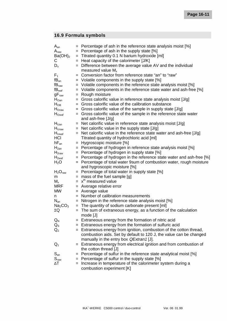
IKA-WERKE C5000 control / duo-control Ver. 06 01.99
Page 16-11
16.9 Formula symbols
Aan = Percentage of ash in the reference state analysis moist [%]Araw = Percentage of ash in the supply state [%]Ba(OH)2 = Titrated quantity 0.1 N barium hydroxide [ml]C = Heat capacity of the calorimeter [J/K]Dx = Difference between the average value AV and the individual
measured value Mx
F1 = Conversion factor from reference state “an” to “raw”fBan = Volatile components in the supply state [%]fBraw = Volatile components in the reference state analysis moist [%]fBwaf = Volatile components in the reference state water and ash-free [%]gFraw = Rough moistureHOan = Gross calorific value in reference state analysis moist [J/g]HOB = Gross calorific value of the calibration substanceHOraw = Gross calorific value of the sample in supply state [J/g]HOwaf = Gross calorific value of the sample in the reference state water
and ash-free [J/g]HUan = Net calorific value in reference state analysis moist [J/g]HUraw = Net calorific value in the supply state [J/g]HUwaf = Net calorific value in the reference state water and ash-free [J/g]HCl Titrated quantity of hydrochloric acid [ml]hFan = Hygroscopic moisture [%]H2an = Percentage of hydrogen in reference state analysis moist [%]H2raw = Percentage of hydrogen in supply state [%]H2waf = Percentage of hydrogen in the reference state water and ash-free [%]H2O = Percentage of total water 9sum of combustion water, rough moisture
and hygroscopic moisture [%]H2Oraw = Percentage of total water in supply state [%]m = mass of the fuel sample [g]Mx = xth measured valueMRF = Average relative errorMW = Average valuen = Number of calibration measurementsNan = Nitrogen in the reference state analysis moist [%]Na2CO3 = The quantity of sodium carbonate present [ml]ΣQ = The sum of extraneous energy, as a function of the calculation
mode [J]QN = Extraneous energy from the formation of nitric acidQS = Extraneous energy from the formation of sulfuric acidQZ = Extraneous energy from ignition, combustion of the cotton thread,
combustion aids. Set by default to 120 J, the value can be changedmanually in the entry box QExtran1 [J].
Q1 = Extraneous energy from electrical ignition and from combustion ofthe cotton thread [J]
San = Percentage of sulfur in the reference state analytical moist [%]Sraw = Percentage of sulfur in the supply state [%]∆T = Increase in temperature of the calorimeter system during a
combustion experiment [K]
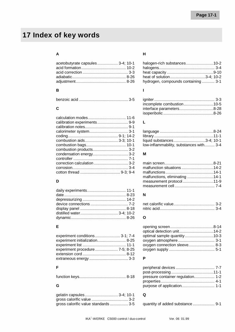
IKA-WERKE C5000 control / duo-control Ver. 06 01.99
Page 17-1
17 Index of key words
A
acetobutyrate capsules .................. 3-4; 10-1acid formation....................................... 10-2acid correction ........................................ 3-3adiabatic............................................... 8-26adjustment............................................ 8-26
B
benzoic acid ........................................... 3-5
C
calculation modes................................. 11-6calibration experiments ........................... 9-9calibration notes...................................... 9-1calorimeter system.................................. 3-1coding............................................ 9-1; 14-2combustion aids............................. 3-3; 10-1combustion bags................................... 10-1combustion products............................... 3-2condensation energy............................... 3-2controller ................................................ 7-1correction calculation .............................. 3-2corrosion................................................. 3-4cotton thread ................................... 9-3; 9-4
D
daily experiments.................................. 11-1date ...................................................... 8-23depressurizing ...................................... 14-2device connections ................................. 7-2display panel ........................................ 8-18distilled water................................. 3-4; 10-2dynamic................................................ 8-26
E
experiment conditions...................... 3-1; 7-4experiment initialization......................... 8-25experiment list ...................................... 11-1experiment procedure.................... 7-5; 8-25extension cord ...................................... 8-12extraneous energy .................................. 3-3
F
function keys......................................... 8-18
G
gelatin capsules............................. 3-4; 10-1gross calorific value ................................ 3-2gross calorific value standards ................ 3-5
H
halogen-rich substances........................10-2halogens................................................. 3-4heat capacity .........................................9-10heat of solution...............................3-4; 10-2hydrogen, compounds containing ........... 3-1
I
igniter ..................................................... 3-3incomplete combustion..........................10-5interface parameters..............................8-28isoperibolic ............................................8-26
L
language ...............................................8-24library ....................................................11-1liquid substances............................3-4; 10-1low-inflammability, substances with......... 3-4
M
main screen...........................................8-21malfunction situations ............................14-2malfunctions ..........................................14-1malfunctions, eliminating .......................14-1measurement protocol ...........................11-9measurement cell ................................... 7-4
N
net calorific value.................................... 3-2nitric acid................................................ 3-4
O
opening screen......................................8-14optical detection unit..............................14-2optimal sample quantity .........................10-3oxygen atmosphere ................................ 3-1oxygen connection sleeve....................... 8-3oxygen supply ........................................ 5-1
P
peripheral devices .................................. 7-7post-processing .....................................11-1pressure container regulation.................. 1-2properties ............................................... 4-1purpose of application............................. 1-1
Q
quantity of added substance ................... 9-1
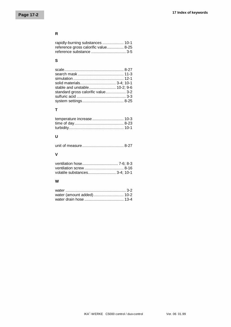
17 Index of keywords
IKA-WERKE C5000 control / duo-control Ver. 06 01.99
Page 17-2
R
rapidly-burning substances ................... 10-1reference gross calorific value............... 8-25reference substance ............................... 3-5
S
scale..................................................... 8-27search mask ......................................... 11-3simulation ............................................. 12-1solid materials................................ 3-4; 10-1stable and unstable........................ 10-2; 9-6standard gross calorific value.................. 3-2sulfuric acid ............................................ 3-3system settings..................................... 8-25
T
temperature increase ............................ 10-3time of day............................................ 8-23turbidity................................................. 10-1
U
unit of measure..................................... 8-27
V
ventilation hose................................ 7-6; 8-3ventilation screw ................................... 8-16volatile substances......................... 3-4; 10-1
W
water ...................................................... 3-2water (amount added)........................... 10-2water drain hose ................................... 13-4