
INDICE INDEX INHALTSVERZEICHNIS A
26
A1 CT16 IGBD 3.0 Basic A INDICE INDEX INHALTSVERZEICHNIS Generalità General information Allgemeines A Riduttori a vite senza fine RI - RMI Worm gearboxes RI - RMI Schneckengetriebe RI - RMI B R Riduttori a vite senza fine combinati CRI - CRMI Double worm gearboxes CRI - CRMI Doppelschneckengetriebe CRI - CRMI Riduttori a vite senza fine con precoppia CR - CB - size 40-50-70-85-110 Helical worm gearboxes CR - CB - size 40-50-70-85-110 Stirnradschneckengetriebe CR - CB - size 40-50-70-85-110 Riduttori a vite senza fine UI - UMI Worm gearboxes UI - UMI Schneckengetriebe UI - UMI C U CR C C Riduttori a vite senza fine con precoppia CR - CB - size 130-150-180-215-250 Helical worm gearboxes CR - CB - size 130-150-180-215-250 Stirnradschneckengetriebe CR - CB - size 130-150-180-215-250 LIMIT Limitatore di coppia Torque limiter Rutschkupplung Riduttori a vite senza fine Worm gearboxes SchneckengetriebeI Rinvii angolari Z Right angle Z Winkelgetriebe Z E Z F Rinvii angolari ZL Right angle ZL Winkelgetriebe ZL ZL ZL H Variatori meccanici WM Mechanical variators WM Mechanischen Verstellgetriebe WM WM D Riduttoria vite senza fine IMPORT WI-WMI Worm gearboxes IMPORT WI-WMI Schneckengetriebe IMPORT WI-WMI W Posizioni di montaggio Mounting position Montagepositionen Z Z1 Gestione Revisioni Cataloghi STM Managing STM Catalog Revisions Management Wiederholt Kataloge STM Z5 M1 M4 M5
Transcript of INDICE INDEX INHALTSVERZEICHNIS A

A1CT16 IGBD 3.0
Basic
AINDICEINDEXINHALTSVERZEICHNIS
GeneralitàGeneral informationAllgemeines
A
Riduttori a vite senza fine RI - RMIWorm gearboxes RI - RMISchneckengetriebe RI - RMI
B
R
Riduttori a vite senza fine combinati CRI - CRMIDouble worm gearboxes CRI - CRMIDoppelschneckengetriebe CRI - CRMI
Riduttori a vite senza fine con precoppia CR - CB - size 40-50-70-85-110Helical worm gearboxes CR - CB - size 40-50-70-85-110Stirnradschneckengetriebe CR - CB - size 40-50-70-85-110
Riduttori a vite senza fine UI - UMIWorm gearboxes UI - UMISchneckengetriebe UI - UMIC
U
CR
C
C
Riduttori a vite senza fine con precoppia CR - CB - size 130-150-180-215-250Helical worm gearboxes CR - CB - size 130-150-180-215-250Stirnradschneckengetriebe CR - CB - size 130-150-180-215-250
LIMIT
Limitatore di coppiaTorque limiterRutschkupplung
Riduttori a vite senza fineWorm gearboxesSchneckengetriebeI
Rinvii angolari ZRight angle ZWinkelgetriebe ZE
Z
FRinvii angolari ZLRight angle ZLWinkelgetriebe ZLZL
ZL
HVariatori meccanici WMMechanical variators WMMechanischen Verstellgetriebe WMWM
DRiduttoria vite senza fine IMPORT WI-WMIWorm gearboxes IMPORT WI-WMISchneckengetriebe IMPORT WI-WMIW
Posizioni di montaggioMounting positionMontagepositionenZ Z1
Gestione Revisioni Cataloghi STMManaging STM Catalog RevisionsManagement Wiederholt Kataloge STM
Z5
M1M4 M5

CT16 IGBD 3.0A2
Basic
1.0 ALLGEMEINES
SIMBOLOSYMBOLSYMBOL
DEFINIZIONE DEFINITION DEFINITIONUNITA’ DI MISURA
MEASUREMENT UNITMAßEINHEIT
Fr 1-2 Carico Radiale Radial load Radialbelastung N1N=0.1daN � 0.1kg
Fa 1-2 Carico assiale Axial load Axialbelastung NDimensioni Dimensions Abmessungen mm
FS Fattore di servizio Service factor Betriebsfaktor
FS’Fattore di serviziomotoriduttore Gear motors service factor Betriebsfaktor Getriebemotoren
Kg Massa Mass Masse kgT2M Momento torcente riduttore Output torque Drehmoment Getriebe Nm
1Nm=0.1daNm�0.1kgmT2 Momento torcente motorid. Gear motor torque Drehmoment Getriebemotor NmP Potenza motore Gear unit power Leistung Getriebe kW
1kW = 1.36 HP (PS)
Ptn Potenza limite termico Limit thermal capacity Thermische Leistungsgrenze kWPc Potenza corretta Correct power Tatsächliche Leistung kWP1 Potenza motoriduttore Gear motor power Leistung Getriebemotor kWP’ Potenza richiesta in uscita Output power Erforderliche
AbtriebsleistungkW
RD Rendimento dinamico Dynamic efficiency Dynamischer WirkungsgradRS Rendimento statico Static efficiency Statischer Wirkungsgradir Rapporto di trasmissione Ratio Übersetzungsverhältnisn1 Velocità albero entrata Input speed Antriebsdrehzahl
min-1 1 min-1 = 6.283 rad.n2 Velocità albero in uscita Output speed AbtriebsdrehzahlTc Temperatura ambiente Ambient temperature Umgebungstemperatur °C
1.1 Measurement units
Tab. 1.2
1.2 Input speed
Tab. 1.1
1.1 Maßeinheiten
1.2 Antriebsdrehzahl
1.0 GENERALITA’
1.1 Unita’ di misura
Tutte le prestazioni dei riduttori , variatorimeccanici e rinvii angolari sono calcolatein base alle seguenti velocità in entrata:
1.2 Velocità in entrata
Velocità inferiori a 1400 min-1 ottenute conl’ausilio di riduzioni esterne o di azionamen-ti, sono sicuramente favorevoli al buon fun-zionamento del riduttore il quale può ope-rare con temperature di funzionamentoinferiori a vantaggio di tutto il cinemati-smo (in particolare nei riduttori a vite sen-za fine).E’ necessario però considerare chevelocità molto basse non consentonoun' efficace lubrificazione di tutto ilgruppo, per cui tale eventualità dovràessere segnalata per poter effettuareschermature dei cuscinetti superiorinei riduttori delle taglie maggiori o ap-plicare sistemi di lubrificazione forzata(pompa di lubrificazione).
1.0 GENERAL INFORMATION
All performances of gearboxes and varia-tors are calculated according to the follo-wing input speeds:
Alle Wirkungsgrade der Getriebe und Ver-stellgetriebe werden auf der Grundlage fol-gender Antriebsdrehzahlen berechnet:
Speeds lower than 1400 rpm obtained bymeans of external reductions or drives,surely contribute to the good working ofthe gearbox which can operate at lowerworking temperatures to the advantage ofthe whole kinematic movement (in parti-cular in case of the worm gearboxes).However, please note that very lowspeeds do not allow an efficacious lu-brication of the whole unit. Thereforethis case shall be indicated to screenthe upper bearings of the gearboxes oflarger sizes or to apply systems withforced lubrications (lubrication pump).
Drehzahlen unter 1400 min-1, die mit Hilfeäußerer Untersetzungen oder Antriebe er-halten werden, sind für den optimalen Be-trieb des Getriebes vorteilhaft, denn sokann dieses mit niedrigen Betriebstempe-raturen arbeiten, was sich zum Vorteil dergesamten Getriebegruppe auswirkt (insbe-sonders bei Schneckengetrieben).Es muß jedoch berücksichtigt werden,daß sehr niedrige Drehzahlen keine wirk-same Schmierung der gesamten Grup-pe zulassen. Wird mit solch niedrigenDrehzahlen gearbeitet, muß dies ange-geben werden, damit wir bei den grö-ßeren Getrieben die oberen Lager ab-schirmen oder Zwangsschmiersysteme(Schmierpumpe) einsetzen können.
UI - RI - WI
25 28 30 40 50 63 70 75 85 90 110 130 150 180 215 2501500 < n1 < 3000 OK OK OK OK OK Contattare il ns. servizio tecnico
Contact our technical deptWenden Sie sich an unseren technischen Servicen1 > 3000
RiduttoriGearboxes
Getriebe
a vite senza finewormgearboxes
Schneckengetriebe
a vite senza fine combinaticombined wormgearboxes
Kombinierte Schneckengetriebe
a vite senza fine conprecoppia
Helical wormgearboxesStirnrad Schneckengetriebe
variatori meccanicimechanical
variatorsVerstell-Getriebe
rinvii angolariright angle gearsWinkelgetriebe
UI - RI - WI CRI-CWI CR VM - WM Z - ZL
n1(rpm)
2800* — 2800 (max) 2800 (max) 2800 (max)1400 1400 1400 1400 1000900 — 900 900 900500 — 500 — 500
* Nei riduttori a vite senza fine, persituazioni con velocità di ingressoparticolari, attenersi alla tabella sottoriportata che evidenzia le situazioni critiche.
* As far as worm reduction units areconcerned, in situations with special inputspeeds, adhere to the table below thathighlights any critical situations.
* Bei den Schneckengetrieben ist unterBedingungen mit besonderenAntriebsgeschwindigkeiten dienachstehend aufgeführte Tabelle zubeachten, die kritische Situationenhervorhebt.

A3CT16 IGBD 3.0
Basic
A
Tab. 1.3
1.3 Service factor
The service factor FS permits approximatequalification of the type of application, tak-ing into account the type of load (A,B,C),length of operation h/d (hours/day) and thenumber of start-up/hour. The coefficientthus calculated must be equal or less thanthe motorgear unit service factor FS’ givenby the rated torque of gear unit T2M as in-dicated in the catalogue and the torque M’required by the application.The FS values reported in Table 1.3 referto a drive unit with an electric motor. If acombustion engine is used, a multiplica-tion factor of 1.3 must be applied for aseveral-cylinder engine, 1.5 for a single-cylinder engine.If the electric motor applied is self-braking,consider twice the number of start-up thanthose actually required.
1.3 Betriebsfaktor
Mit Hilfe des Betriebsfaktors FS kann in ei-ner ersten Annäherung das richtige Unter-setzungsgetriebe für die gewünschte An-wendungsart ermittelt werden. Dabei sindfolgende Werte zu beachten: Art der Last(A, B, C), Betriebsstunden pro Tag (h/d),Anzahl der Starts pro Stunde. Der so er-mittelte Koeffizient sollte dem Betriebsfak-tor FS’, der sich aus dem Verhältniszwischen dem Nenndrehmoment des Ge-triebes T2M (s. Katalog) und dem für dieAnwendung erforderlichen DrehmomentM’ ergibt, entweder entsprechen oderniedriger liegen.Die FS-Werte, die in Tabelle 1.3 ange-geben werden, beziehen sich auf den Antriebmit Elektromotor. Wird ein Verbrennungs-motor verwendet, so ist bei mehreren Zy-lindern ein Multiplikationsfaktor von 1,3und bei einem Einzylindermotor ein Faktorvon 1,5 zu berücksichtigen.Ist der verwendete Elektromotor einBremsmotor, so ist die Zahl der tatsächli-chen Startvorgänge zu verdoppeln.
1.3 Fattore di servizio
Il fattore di servizio FS permette di qualifi-care, in prima approssimazione, la tipolo-gia dell’applicazione tenendo conto dellanatura del carico (A, B, C), della durata difunzionamento h/d (ore giornaliere) e delnumero di avviamenti/ora. Il coefficientecosì trovato dovrà essere uguale o inferio-re al fattore di servizio del motoriduttore odel motorinvio angolare FS’ dato dal rap-porto fra la coppia nominale del riduttoreT2M indicata a catalogo e la coppia M’ ri-chiesta dall’applicazione .I valori di FS indicati nella tab. 1.3, sonorelativi all’azionamento con motore elettri-co, se utilizzato un motore a scoppio, sidovrà tenere conto di un fattore di moltipli-cazione 1.3 se a più cilindri e 1.5 se mo-nocilindro.Se il motore elettrico applicato è autofre-nante, considerare un numero di avvia-menti doppio di quello effettivamenterichiesto.
FATTORE DI SERVIZIO / SERVICE FACTOR / BETRIEBSFAKTORFS
Classe di caricoLoad classLastklasse
h/dN. AVVIAMENTI/ORA / N. START-UP/HOUR / ANZAHL DER STARTVORGÄNGE PRO STUNDE
2 4 8 16 32 63 125 250 500
A
4 0.85 0.9 0.9 0.93 0.98 1.03 1.06 1.1 1.28 1.0 1.0 1.1 1.1 1.15 1.2 1.24 1.3 1.3
16 1.2 1.2 1.25 1.3 1.35 1.45 1.5 1.5 1.5524 1.4 1.4 1.45 1.5 1.55 1.6 1.65 1.7 1.75
APPLICAZIONI / APPLICATIONS / ANWENDUNGEN
Carico uniformeUniform load
Gleichmäßig verteilte Last
Agitatori per liquidi puri Pure liquid agitators Rührwerke für reine FlüssigkeitenAlimentatori per fornaci Fournace feeders Beschickungsvorrichtungen für
BrennöfenAlimentatori a disco Disc feeders TelleraufgeberFiltri di lavaggio con aria Air laundry filters SpülluftfilterGeneratori Generators GeneratorenPompe centrifughe Centrifugal pumps KreiselpumpenTrasportatori con carico uniforme Uniform load conveyors Förderer mit gleichmäßig verteilter Last
Classe di caricoLoad classLastklasse
h/dN. AVVIAMENTI/ORA / N. START-UP/HOUR / ANZAHL DER STARTVORGÄNGE PRO STUNDE
2 4 8 16 32 63 125 250 500
B
4 1.11 1.12 1.15 1.19 1.23 1.28 1.32 1.36 1.408 1.29 1.31 1.34 1.40 1.45 1.51 1.56 1.60 1.64
16 1.54 1.56 1.59 1.65 1.71 1.78 1.84 1.90 1.9624 1.73 1.75 1.80 1.90 1.97 2.05 2.10 2.16 2.22
APPLICAZIONI / APPLICATIONS / ANWENDUNGEN
Carico con urti moderatiModerate shock load
Last mit mäßigen Stößen
Agitatori per liquidi e solidi Liquid and solid agitators Rührwerke für Flüssigkeiten und FeststoffeAlimentatori a nastro Belt conveyors BandfördererArgani con medio servizio Medium service winches Mittlere WindenFiltri con pietre e ghiaia Stone and gravel filters Stein- und KiesfilterViti per espulsione acqua Dewatering screws AbwasserschneckenFlocculatori Flocculator FlockvorrichtungenFiltri a vuoto Vacuum filters VakuumfilterElevatori a tazze Bucket elevators BecherwerkeGru Cranes Krane
Classe di caricoLoad classLastklasse
h/dN. AVVIAMENTI/ORA / N. START-UP/HOUR / ANZAHL DER STARTVORGÄNGE PRO STUNDE
2 4 8 16 32 63 125 250 500
C
4 1.46 1.46 1.48 1.51 1.57 1.61 1.62 1.64 1.668 1.71 1.71 1.73 1.76 1.82 1.86 1.87 1.89 1.89
16 2.04 2.05 2.07 2.10 2.15 2.20 2.21 2.23 2.2324 2.31 2.31 2.33 2.36 2.42 2.48 2.52 2.54 2.56
APPLICAZIONI / APPLICATIONS / ANWENDUNGEN
Carico con forti urtiHeavy shock load
Last mit starken Stößen
Argani per servizio pesante Heavy duty hoists Winden für schwere LastenEstrusori Extruders ExtruderCalandre per gomma Crusher rubber calenders GummikalanderPresse per mattoni Brick presses ZiegelpressenPiallatrici Planing machine HobelmaschinenMulini a sfera Ball mills Kugelmühlen

CT16 IGBD 3.0A4
Basic
About mechanical variator, note that themaximum number of starts allowed to pre-serve variator life is 8 - 10 starts per min-ute.
Um die maximale Lebensdauer zu ge-währleisten, sollten maximal 8-10 Schal-tungen pro Minute getätigt werden.
Nel caso di variatore meccanico è neces-sario evidenziare inoltre che il numero diavviamenti massimo consentito senzaprovocare conseguenze sulla durata delvariatore, non deve superare gli 8 - 10 alminuto
1.3 Service factor
Ambient temperature must also be takeninto consideration when choosingwormgearboxes (Tamb): the service factormust be corrected as follows:
1.3 Betriebsfaktor
Im Falle der Schneckengetriebe muß dieRaumtemperatur (Traum): berücksichtigtwerden: der Betriebsfaktor muß also wiefolgt bereinigt werden:
1.3 Fattore di servizio
Nel caso di riduttori a vite senza fine, oc-corre tener conto della temperatura am-biente (Tamb): il fattore di servizio va alloracorretto come segue:
Tamb Fattore di servizio / Service factor / Betriebsfaktor
30 � 40 °C FS x 1.10
40 � 50 °C FS x 1.2
50 � 60 °C FS x 1.4
� 60 °C Interpellare ns. Assistenza Tecnica / Contact our Technical Assistance Service / Bitte technischen Service hinzuziehen
Mechanischen Verstellgetrieben ca. 0,84bei Maximalgeschwindigkeit.Der Wirkungsgrad der Winkelgetriebebeträgt 0.94-0.97. Bei Schneckengetrie-ben ist es hingegen zweckmäßig, den Wir-kungsgrad ausgehend vomUntersetzungsverhältnis zu bestimmen,wobei zwischen dynamischem Wir-kungsgrad (die Werte sind jeweils in denLeistungstabellen aufgeführt) und stati-schem Wirkungsgrad zu unterscheiden ist(siehe tab 1.6) . Der dynamische Wir-kungsgrad RD erhöht sich bei einer Ver-größerung des Steigungswinkels (beiniedrigen Untersetzungsverhältnissen),bei der Verwendung von synthetischenanstatt Mineralölen und bei Erhöhung derGleitgeschwindigkeit.Während der Einlaufzeit ist der Wert we-sentlich niedriger als derjenige in den Lei-stungstabellen.
Der statische Wirkungsgrad RS oderAnlaufwirkungsgrad ist bei der richti-gen Wahl des Untersetzungsgetriebessehr wichtig, speziell bei solchenAnwendungen, bei denen der optimaleBetriebszustand nicht erreicht wird(Aussetzbetrieb).Ein Getriebe ist statisch selbsthemmend(kann von der Abtriebswelle nicht in Ganggesetzt werden), wenn sein statischer Wir-kungsgrad (RS) unter 0.5 liegt. Bei Stößenoder Vibrationen kann dies jedoch trot-zdem vorkommen. Ein Getriebe ist dyna-misch selbsthemmend (sofortigesBlockieren der Schnekke, wenn die Ursa-che dieser Drehung nicht mehr vorhandenist) wenn sein dynamischer WirkungsgradRD unter 0.5
Equal to 0.84 in case of variators at maxi-mum speed.In right angle drives the dynamic efficiencyRD can be considered equal to 0.94 and0.97It is advisable to determine the efficiencyaccording to the reduction ratio in theworm gearboxes and to make a distinc-tion between the dynamic efficiency(these values are shown in the perfor-mance tables)and static efficiency (seetab. 1.6).Dynamic efficiency RD increases gradu-ally with an increase of the helix angle(low reduction04 ratios), with a changefrom mineral to synthetic lubricants andwith an increase of rubbing speed.
During running in period RD value is sub-stantially inferior to the one listed in theperformance table.
Static efficiency RS or starting effi-ciency is very important with respect tothe correct selection of the gearbox es-pecially on applications where the opti-mal operating conditions are neverattained (intermittent duty).
A gearbox is statically irreversible (cannotbe put into operation by output shaft),when its RS is less than 0.5. In the case ofshocks or vibrations this can happen any-way.A gearbox is dynamically irreversible (in-stantaneous stop lock of wormshaftrotation if the cause of the same rotation isnot present anymore), when its RD valueis less than 0.5.
Nei variatori meccanici vale circa 0.84 allavelocità massima.Nei rinvii angolari il rendimento dinamicoRD può essere considerato pari a0.94-0.97.Nei riduttori a vite senza fine invece, è op-portuno definire il rendimento in base alrapporto di riduzione distinguendo chiara-mente fra il rendimento dinamico (questivalori sono riportati nelle tabelle delle pre-stazioni) e il rendimento statico (tab. 1.6).ll rendimento dinamico RD aumenta con ilcrescere dell’angolo dell’elica (bassi rap-porti di riduzione), con il passare da oli mi-nerali a sintetici e con l’incremento dellavelocità di strisciamento.
Durante la fase di rodaggio il suo valore ri-sulta essere sensibilmente inferiore rispet-to a quello riportato nelle tabelle delleprestazioni.
Il rendimento statico RS o rendimentodell’avviamento, è molto importante, alfine di una corretta scelta del riduttore,per quelle applicazioni in cui non siraggiungono mai le condizioni di regi-me (servizi intermittenti).
Un riduttore è irreversibile staticamente(non azionabile dall’albero lento) quando ilsuo RS è minore di 0.5. In presenza di urtie vibrazioni tale condizione può non esse-re verificata.Un riduttore è irreversibile dinamicamente(blocco istantaneo della rotazione dellavite qualora non sia più presente la causadella rotazione stessa) quando il suo RD èminore di 0.5.
1.4 Efficiency(and irreversibility)
1.4 Rendimento(ed irreversibilità )
1.4 Wirkungsgrad(und Selbsthemmung)
Tab. 1.4
A5CT16 IGBD 3.0
Basic
A
UI - RIUMI - RMIWI - WMI
Rapporti di riduzione / Reduction ratios/ Übersetzungsverhältnis (ir)
77.5 10 15 20
252830
40 4950
5660 70 80 100
CRI - CWICRMI - CWMI
Rapporti di riduzione / Reduction ratios/ Übersetzungsverhältnis (i1, i2)
77.5 10 15 20
252830
40 4950
5660 70 80 100
CRCB
Rapporti di riduzione / Reduction ratios/ Übersetzungsverhältnis (i2)15 28 49 100
Reversibilità totaleTotal reversibility
Totale Reversibilität
Zona di incertezzaUncertainty zone
Übergangsbereich
Irreversibilità statica /Reversibilità dinamicaStatic irreversibility / Dynamic reversibility
Statische Selbsthemmung / Dynamische Reversibilität
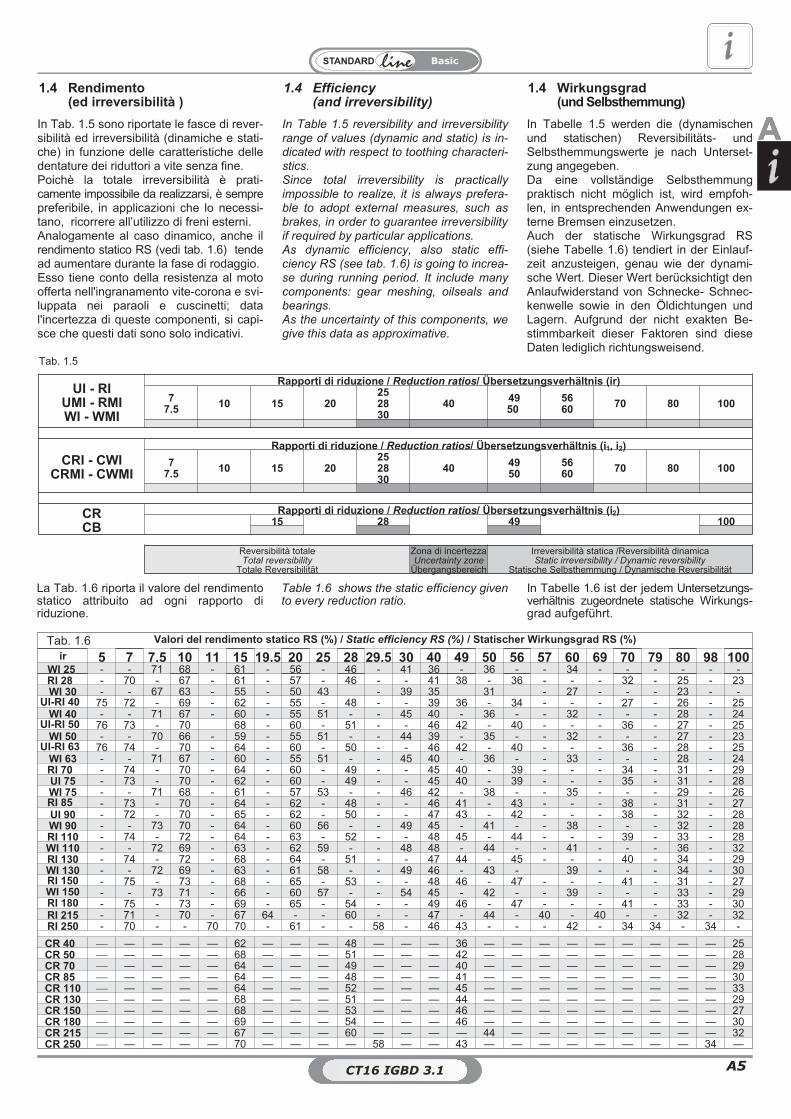
Tab. 1.5
1.4 Efficiency(and irreversibility)
1.4 Rendimento(ed irreversibilità )
1.4 Wirkungsgrad(und Selbsthemmung)
Tab. 1.6
Table 1.6 shows the static efficiency givento every reduction ratio.
In Tabelle 1.6 ist der jedem Untersetzungs-verhältnis zugeordnete statische Wirkungs-grad aufgeführt.
La Tab. 1.6 riporta il valore del rendimentostatico attribuito ad ogni rapporto diriduzione.
In Tabelle 1.5 werden die (dynamischenund statischen) Reversibilitäts- undSelbsthemmungswerte je nach Unterset-zung angegeben.Da eine vollständige Selbsthemmungpraktisch nicht möglich ist, wird empfoh-len, in entsprechenden Anwendungen ex-terne Bremsen einzusetzen.Auch der statische Wirkungsgrad RS(siehe Tabelle 1.6) tendiert in der Einlauf-zeit anzusteigen, genau wie der dynami-sche Wert. Dieser Wert berücksichtigt denAnlaufwiderstand von Schnecke- Schnec-kenwelle sowie in den Öldichtungen undLagern. Aufgrund der nicht exakten Be-stimmbarkeit dieser Faktoren sind dieseDaten lediglich richtungsweisend.
In Table 1.5 reversibility and irreversibilityrange of values (dynamic and static) is in-dicated with respect to toothing characteri-stics.Since total irreversibility is practicallyimpossible to realize, it is always prefera-ble to adopt external measures, such asbrakes, in order to guarantee irreversibilityif required by particular applications.As dynamic efficiency, also static effi-ciency RS (see tab. 1.6) is going to increa-se during running period. It include manycomponents: gear meshing, oilseals andbearings.As the uncertainty of this components, wegive this data as approximative.
In Tab. 1.5 sono riportate le fasce di rever-sibilità ed irreversibilità (dinamiche e stati-che) in funzione delle caratteristiche delledentature dei riduttori a vite senza fine.Poichè la totale irreversibilità è prati-camente impossibile da realizzarsi, è semprepreferibile, in applicazioni che lo necessi-tano, ricorrere all’utilizzo di freni esterni.Analogamente al caso dinamico, anche ilrendimento statico RS (vedi tab. 1.6) tendead aumentare durante la fase di rodaggio.Esso tiene conto della resistenza al motoofferta nell'ingranamento vite-corona e svi-luppata nei paraoli e cuscinetti; datal'incertezza di queste componenti, si capi-sce che questi dati sono solo indicativi.
AA
Valori del rendimento statico RS (%) / Static efficiency RS (%) / Statischer Wirkungsgrad RS (%)
ir 5 7 7.5 10 11 15 19.5 20 25 28 29.5 30 40 49 50 56 57 60 69 70 79 80 98 100WI 25 - - 71 68 - 61 - 56 - 46 - 41 36 - 36 - - 34 - - - - - -RI 28 - 70 - 67 - 61 - 57 - 46 - - 41 38 - 36 - - - 32 - 25 - 23WI 30 - - 67 63 - 55 - 50 43 - 39 35 31 - 27 - - - 23 - -
UI-RI 40 75 72 - 69 - 62 - 55 - 48 - - 39 36 - 34 - - - 27 - 26 - 25WI 40 - - 71 67 - 60 - 55 51 - - 45 40 - 36 - - 32 - - - 28 - 24
UI-RI 50 76 73 - 70 68 - 60 - 51 - - 46 42 - 40 - - - 36 - 27 - 25WI 50 - - 70 66 - 59 - 55 51 - - 44 39 - 35 - - 32 - - - 27 - 23
UI-RI 63 76 74 - 70 - 64 - 60 - 50 - - 46 42 - 40 - - - 36 - 28 - 25WI 63 - - 71 67 - 60 - 55 51 - - 45 40 - 36 - - 33 - - - 28 - 24RI 70 - 74 - 70 - 64 - 60 - 49 - - 45 40 - 39 - - - 34 - 31 - 29UI 75 - 73 - 70 - 62 - 60 - 49 - - 45 40 - 39 - - - 35 - 31 - 28WI 75 - - 71 68 - 61 - 57 53 - - 46 42 - 38 - - 35 - - - 29 - 26RI 85 - 73 - 70 - 64 - 62 - 48 - - 46 41 - 43 - - - 38 - 31 - 27UI 90 - 72 - 70 - 65 - 62 - 50 - - 47 43 - 42 - - - 38 - 32 - 28WI 90 - - 73 70 - 64 - 60 56 - - 49 45 - 41 - - 38 - - - 32 - 28RI 110 - 74 - 72 - 64 - 63 - 52 - - 48 45 - 44 - - - 39 - 33 - 28WI 110 - - 72 69 - 63 - 62 59 - - 48 48 - 44 - - 41 - - - 36 - 32RI 130 - 74 - 72 - 68 - 64 - 51 - - 47 44 - 45 - - - 40 - 34 - 29WI 130 - - 72 69 - 63 - 61 58 - - 49 46 - 43 - 39 - - - 34 - 30RI 150 - 75 - 73 - 68 - 65 - 53 - - 48 46 - 47 - - - 41 - 31 - 27WI 150 - - 73 71 - 66 - 60 57 - - 54 45 - 42 - - 39 - - - 33 - 29RI 180 - 75 - 73 - 69 - 65 - 54 - - 49 46 - 47 - - - 41 - 33 - 30RI 215 - 71 - 70 - 67 64 - - 60 - - 47 - 44 - 40 - 40 - - 32 - 32RI 250 - 70 - - 70 70 - 61 - - 58 - 46 43 - - - 42 - 34 34 - 34 -
CR 40 � — — — — 62 — — — 48 — — — 36 — — — — — — — — — 25CR 50 � — — — — 68 — — — 51 — — — 42 — — — — — — — — — 28CR 70 � — — — — 64 — — — 49 — — — 40 — — — — — — — — — 29CR 85 � — — — — 64 — — — 48 — — — 41 — — — — — — — — — 30CR 110 � — — — — 64 — — — 52 — — — 45 — — — — — — — — — 33CR 130 � — — — — 68 — — — 51 — — — 44 — — — — — — — — — 29CR 150 � — — — — 68 — — — 53 — — — 46 — — — — — — — — — 27CR 180 � — — — — 69 — — — 54 — — — 46 — — — — — — — — — 30CR 215 � — — — — 67 — — — 60 — — — — 44 — — — — — — — — 32CR 250 � — — — — 70 — — — — 58 — — 43 — — — — — — — — 34 —
CT16 IGBD 3.0CT16 IGBD 3.1

CT16 IGBD 3.0A6
Basic
1.5 Backlash
Values of the output shaft backlash onwormgearboxes are shown in table Suchvalues are expressed in minute (') and areapproximate as they can change accord-ing to temperature and wear.
For particular applications, gearboxeswith low backlash adjustable backlashare available upon request.
1.5 Gioco angolare
Nella tab riportiamo i valori del gioco an-golare riscontrabili sull’albero in uscita neiriduttori a vite senza fine.Questi valori, espressi in primi di grado (‘),sono indicativi in quanto possono variarein funzione della temperatura e dell’usura.
Su richiesta, per applicazioni partico-lari, si possono fornire riduttori congiochi angolari inferiori.
1.5 Flankenspiel
Für die Schneckengetriebe ist das Spielder Abtriebswelle in Tabelle (in Winkelmi-nuten ’) aufgeführt.Diese Werte sind Richtwerte, da sie vonder Temperatur und vom Verschleiß ab-hängen.
Für spezielle Anwendungen liefern wirauf Wunsch spielfreie Untersetzungs-getriebe bzw. mit einstellbarem Flan-kenspiel.
1.6 Lubrificazione 1.6 Lubrication 1.6 Schmierung
La lubrificazione dei riduttori, variatori erinvii angolari è consentita mediante un si-stema misto bagno olio e sbattimento, chegarantisce normalmente la lubrificazionedi tutti i componenti interni al riduttore, rin-vio angolare e/o variatore.Per quelle posizioni di montaggio caratte-rizzate da assi di rotazione verticali,vengono adottate particolari soluzioni alfine di garantire una buona lubrificazioneanche degli organi presenti nelle posizionipiù sfavorevoli.I riduttori a vite senza fine sono caratteriz-zati da una elevata componente di stri-sciamento, variabile a seconda dellecaratteristiche di dentatura dell' ingranag-gio e delle velocità di rotazione del cine-matismo, e per questo motivo necessitanodi una accurata lubrificazione. Per questotipo di riduttori usiamo e consigliamo oli abase sintetica, che migliorano il rendimen-to e possiedono una maggiore stabilità diviscosità. E’ importante che gli additiviE.P. presenti negli oli siano blandi e nonagressivi nei confronti del bronzo e delleguarnizioni. La lubrificazione a grasso èconsigliata solo con grassi a base sinteticae molto fluidi (NLGI 00); vengono preferitiper esercizi con elevati urti e per funziona-menti intermittenti.Usando il grasso anzichè l’olio, si ha unminor smaltimento del calore, una riduzio-ne del rendimento, un incremento dell’usu-ra e una minore lubrificazione di tutti icomponenti.
Gearboxes and variators lubrication is pro-vided trough a combination of oil immer-sion and oil-splash patterns, whichnormally guarantees the lubrication of allinternal components.
For some mounting positions, typicallythose featuring a vertical shaft, provisionsare made to guarantee lubrication of eventhe least favourably located drive compo-nents.
Wormgearboxes are characterized by anhigh sliding velocity, which depends byteeth's characteristics and input speed,and this is why they need a proper lubrica-tion.For this kind of gearboxes STM use andsuggest synthetic based oils, which in-crease the dynamic efficiency and guaran-tee longer duration and higher viscositystability.It is very important that E.P. additives pre-sent in lubricants are not aggressive to-wards bronze and oilseals.Grease lubrication is advisable only ifsynthetic based and fluid grease is used(NLGI 00). It is preferable to use such alubrication when having heavy shocks andintermittent duties.Grease used in place of oil contributes toa more difficult elimination of heat, a lowerefficiency and an increase in wear andtear as well as a lower lubrication of allcomponents.
Die Schmierung der Getriebe und der Va-riatoren erfolgt über ein Mischverfahrenmit Ölbad- und Tauchbadschmierung. Da-durch kann in der Regel die Schmierungaller internen Bestandteile des Getriebesoder des Variators gewährleistet werden.Bei Montagepositionen mit vertikalenDrehachsen werden spezielle Lösungenangewandt, um auch die Bestandteile inschwer erreichbaren Positionen ausrei-chend zu schmieren.Die Schneckengetriebe weisen eine hoheReibungskomponente auf, die jeweils hin-sichtlich der Untersetzung und der Dreh-geschwindigkeit des Getriebes variiert.Daher erfordert dieser Getriebetyp einesorgfältige Schmierung. Empfehlenswertist synthetisches Öl, das den Wirkungs-grad steigert und eine höhere Stabilität imHinblick auf die Viskosität aufweist.Wichtig ist, daß die E.P.-Additive der Ölemild sind und die Bronze sowie die Dich-tungen nicht angreifen.Für die Schmierung mit Fett empfehlenwir, nur hochviskose (NLGI 00) Fette mitsynthetischer Base zu verwenden, diesewerden für den aussetzenden Betrieb vor-gezogen.Wird Fett anstelle von Öl verwendet, soresultiert hieraus eine verminderteSchmierung aller Komponenten, eineniedrigere Wärmeabgabe, ein niedrigererWirkungsgrad und ein höherer Verschleiß.
RI-RMIUI-UMIWI-VMI
CRICRMI
Gioco angolareBacklash
Flankenspiel (')CBCR
Gioco angolareBacklash
Flankenspiel (')Z
ZL
Gioco angolareBacklash
Flankenspiel (')Min Max Min Max Min Max
28 .../28 5.5’ 17’ �
Contattare il ns. servizio tecnicoContact our technical dept.
Wenden Sie sich an unseren technischenVertriebsservice
40 .../40 4.5’ 14’ 40 4.5’ 14’50 .../50 3.5’ 12.5’ 50 3.5’ 12.5’63 .../63 3.5’ 12.5’ �
70 .../70 3’ 11.5’ 70 3’ 11.5’75 — 3’ 11’ �
85 .../85 3’ 11’ 85 3’ 11’90 — 3' 10' �
110 .../110 2.5’ 9.5’ 110 2.5’ 9.5’130 .../130 2.5' 9.5' 130 2.5' 9.5'150 .../150 2.5' 9.5' 150 2.5' 9.5'180 .../180 2.5' 9.5' 180 2.5' 9.5'215 .../215 2.5' 6.5' 215 2.5' 6.5'250 .../250 2.5' 6.5' 250 2.5' 6.5'

A7CT16 IGBD 3.0
Basic
AGli oli disponibili appartengono general-mente a tre grandi famiglie:1) Oli minerali2) Oli sintetici Poli-Alfa-Olefine3) Oli sintetici Poli-Glicole
La scelta più appropriata è generalmentelegata alle condizioni di impiego. riduttorinon particolarmente caricati e con un ciclodi impiego discontinuo. senza escursionitermiche importanti, possono certamenteessere lubrificati con olio minerale.Nei casi di impiego gravoso, quando i ri-duttori saranno prevedibilmente caricatimolto ed in modo continuativo, con conse-guente prevedibile innalzamento dellatemperatura, è bene utilizzare lubrificantisintetici tipo polialfaolefine (PAO).
Gli oli di tipo poliglicole (PG) sono da uti-lizzare strettamente nel caso di applicazio-ni con forti strisciamenti fra i contatti, adesempio nelle viti senza fine. Debbono es-sere impiegati con grande attenzione poi-ché non sono compatibili con gli altri oli esono invece completamente miscibili con-l'acqua. Questo fenomeno è particolar-mente pericoloso poiché non si nota, madeprime velocemente le caratteristiche lu-brificanti dell'olio.
Oltre a questi già menzionati, ricordiamoche esistono gli oli per l'industria alimenta-re. Questi trovano specifico impiego nel-l'industria alimentare in quanto sonoprodotti speciali non nocivi alla salute. Variproduttori forniscono oli appartenenti a tut-te le famiglie con caratteristiche molto si-mili.
Available oils are typically grouped intothree major classes:1) Mineral oils2) Poly-Alpha-Olefin synthetic oils3) Polyglycol synthetic oils
Oil is normally selected in accordance withenvironmental and operating conditions.Mineral oil is the appropriate choice formoderate load, non-continuous duty appli-cations free from temperature extremes.In severe applications, where gear unitsare to operate under heavy loads in conti-nuous duty and high temperatures are ex-pected, synthetic Poly-Alpha-Olefin oils(PAO) are the preferred choice.
Polyglycol oils (PG) should only be used inapplications involving high sliding friction,as is the case with worm shafts. Theseparticular oils should be used with greatcare, as they are not compatible with otheroils, but are totally mixable with water. Theoil mixed with water cannot be told fromuncontamined oil, but will degrade very ra-pidly.
In addition to the oils mentioned above,there are food-grade oils. These are spe-cial oils harmless to human health for usein the food industry. Oils with similar cha-racteristics are available from a number ofmanufacturers.
Die verfügbaren Öle gehören im Allgemei-nen drei großen Familien an:1) Mineralöle2) Polyalphaolefine-Synthetiköle3) Polyglykol-Synthetiköle
Die angemessene Wahl ist im Allgemei-nen an die Einsatzbedingungen gebun-den. Getriebe, die keinen besondersschweren Belastungen ausgesetzt sindund einem unregelmäßigen Einsatzzyklusunterliegen, ohne starke thermischeAusschläge, können problemlos mit Mine-ralöl geschmiert werden. Bei einem Ein-satz unter harten Bedingungen, d.h. wenndie Getriebe stark und andauernd belastetwerden, woraus sich ein sicherer Tempe-raturanstieg ergibt, sollten Synthetiköle,Typ Polyalphaolefine (PAO), verwendetwerden.Die Öle, Typ Polyglykole (PG), sindausschließlich für einen Einsatz ausgelegt,bei denen es zu starken Reibungen zwi-schen den in Kontakt stehenden Elemen-ten kommt, z.B. bei Schnecken. Bei ihremEinsatz in besondere Aufmerksamkeit er-forderlich, da sie nicht mit anderen Ölenkompatibel sind, sich jedoch vollständigmit Wasser vermischen lassen. Diese Tat-sache erweist sich daher als besondersgefährlich, da sie sich nicht feststellenlässt, jedoch die Schmiereigenschaftendes Öls bereits nach kurzer Zeit un-terdrückt.Über die bereits genannten Öle hinaus,gibt es auch Öle, die speziell für die Le-bensmittelindustrie ausgelegt sind. Diesefinden demzufolge dort ihren Einsatz, daes sich dabei um spezielle Produkte han-delt, die für die Gesundheit unschädlichsind. Die den jeweiligen Familien angehö-rigen Ölsorten werden von verschiedenenHerstellern angeboten; sie weisen jeweilssehr ähnliche Eigenschaften auf.
1.6 Lubrication1.6 Lubrificazione 1.6 Schmierung

CT16 IGBD 3.0A8
Basic
1.6 Lubrication1.6 Lubrificazione 1.6 Schmierung
The operation principle of this variatorsconsists of torque trasmission by frictionwheel: that means to chose a particularkind of oil, able to increase dynamicefficiency and guarantee longercomponent's duration.The tab. is useful for variator lubricantselection
Das Betriebsprinzip dieser Variatorenbesteht in der Übertragung desDrehmoments über Kupplungsräder.Daher ist eine besondere Wahl desSchmiermittels erforderlich, der denWirkungsgrad sowie die Lebensdauer derBestandteile erhöht.Die Tabelle dient der Auswahl desSchmiermittels für die Variatoren.
Il principio di funzionamento diquesti variatori è quello ditrasmettere la coppia attraverso
ruote di frizione: ciò comporta la scelta diun particolare tipo di lubrificante, capacedi migliorare il rendimento e la durata deicomponenti.La tabella è utile per la scelta deilubrificanti da adottare nei variatori.
Tab.1.9-ProduttoreManufacturer
Hersteller
Tipi di olio raccomandati / Recommended oils / Empfohlene Ölsorte
1° 2° 3°
AGIP TRANSMISSION V.E A.T.F. DEXRON FLUID -
BP AUTRAN DX - -
CASTROL TQ DEXRON II - -
CHEVRON A.T.F. DEXRON - -
ESSO A.T.F. DEXRON - -
FINA A.T.F. DEXRON - -
MOBIL A.T.F. 220 - -
SHELL A.T.F. DEXRON SPIRAX S1 ATF TASA SPIRAX S2 ATF AX
Lubrificanti sintetici per uso alimentare / Food-grade synthetic lubricants / Schmiermittel Synthetik für Lebensmittelbereich
SHELL CASSIDA FLUIDS HF32 - -
WM
The Table is useful for gearbox lubricantselection
Tabelle ist bei der Wahl desSchmiermittels nützlich.
La Tab. è utile per la selezione deilubrificanti per riduttori da utilizzare inbase alla loro stabilità alle varietemperature
Manufacturer
Mineral oils(MINERAL)
Poly-Alpha-Olefin synthetic oils(PAO)
Polyglycol synthetic oils(PG)
ISO VG ISO VG ISO VG220 320 460 150 220 320 150 220 320 460
Amb. temp.- Tc [°C] -5° ÷ 25° 0° ÷ 35° 10° ÷ 45° -10° ÷ 25° -5° ÷35° 0° ÷ 50° -10° ÷ 25° -5° ÷ 35° 0° ÷ 50° 10° ÷ 60°
AGIPBlasia
220Blasia320
Blasia460 - Blasia SX
220Blasia SX
320Blasia S
150Blasia S
220Blasia S
320Blasia S
320
ARALDegol BG220 Plus
Degol BG320 Plus
Degol BG460 Plus
Degol PAS150
Degol PAS220
Degol PAS320
Degol GS150
Degol GS220
Degol GS320
Degol GS460
BPEnergol
GR-XP 220Energol
GR-XP 320Energol
GR-XP 460EnersynEPX 150
EnersynEPX 220
EnersynEPX 320
EnersynSG 150
EnersynSG-XP 220
EnersynSG-XP 320
EnersynSG-XP 460
CASTROLAlpha SP
220AlphaSP
320AlphaSP
460Alphasyn EP
150Alphasyn EP
220Alphasyn EP
320Alphasyn PG
150Alphasyn PG
220Alphasyn PG
320Alphasyn PG
460
CHEVRONUltra Gear
220Ultra Gear
320Ultra Gear
460
TegraSyntheticGear 150
TegraSyntheticGear 220
TegraSyntheticGear 320
HiPerSYN150
HiPerSYN220
HiPerSYN320
HiPerSYN460
ESSOSpartan EP
220Spartan EP
320Spartan EP
460Spartan S EP
150Spartan S EP
220Spartan S EP
320Glycolube
150Glycolube
220Glycolube
320Glycolube
460
KLÜBERKlüberoil
GEM 1-220Klüberoil
GEM 1-320Klüberoil
GEM 1-460KlübersynthEG 4-150
KlübersynthEG 4-220
KlübersynthEG 4-320
KlübersynthGH 6-150
KlübersynthGH 6-220
KlübersynthGH 6-320
KlübersynthGH 6-460
MOBILMobilgearXMP 220
MobilgearXMP 320
MobilgearXMP 460
MobilgearSHC XMP150
MobilgearSHC XMP220
MobilgearSHC XMP320 Glygoyle 22 Glygoyle 30 Glygoyle
HE320GlygoyleHE460
MOLIKOTE L-0122 L-0132 L-1115 L-1122 L-1132 - - - -
OPTIMOLOptigear BM
220Optigear BM
320Optigear BM
460
OptigearSynthetic A
150
OptigearSynthetic A
220
OptigearSynthetic A
320
Optiflex A150
Optiflex A220
Optiflex A320
Optiflex A460
PAKELOEROLUBE EPC ISO 150
EROLUBE EPC ISO 220
EROLUBE EPC ISO 320
GEARSINTEPN ISO 150
GEARSINTEPN ISO 220
GEARSINTEPN ISO 320
ALLSINT HSISO 150
ALLSINT HSISO 220
ALLSINT HSISO 320
ALLSINT HSISO 460
PETRONASPETRONASGEAR MEP
150
PETRONASGEAR MEP
220
PETRONASGEAR MEP
320
PETRONASGEAR SYNPAO 150
PETRONASGEAR SYNPAO 220
PETRONASGEAR SYNPAO 320
PETRONASGEAR SYNPAG 150
PETRONASGEAR SYNPAG 220
PETRONASGEAR SYNPAG 320
PETRONASGEAR SYNPAG 460
Q8 Goya 220 Goya 320 Goya 460 El Greco 150 El Greco 220 El Greco 320 Gade 150 Gade 220 Gade 320 Gade 460
SHELLOMALA
S2 GX 220OMALA
S2 GX 320OMALA
S2 GX 460Omala
S4 GXV 150Omala
S4 GXV 220Omala
S4 GXV 320OMALA
S4 WE 150OMALA
S4 WE 220OMALA
S4 WE 320OMALA
S4 WE 460
TEXACOMeropa
220Meropa
320Meropa
460Pinnacle EP
150Pinnacle EP
220Pinnacle EP
320 - Synlube CLP220
Synlube CLP320
Synlube CLP460
TOTALCarter EP
220Carter EP
320Carter EP
460Carter SH
150Carter SH
220Carter SH
320Carter SY
150Carter SY
220Carter SY
320Carter SY
460
TRIBOL 1100/220 1100/320 1100/460 1510/150 1510/220 1510/320 800\150 800\220 800\320 800\460
Food-grade synthetic lubricants
AGIPRocol
FoodlubeHi-Torque 150
—Rocol
FoodlubeHi-Torque 320
ESSO — Gear Oil FM220 —
FUCHSCassida Fluid
GL 150Cassida Fluid
GL 220Cassida Fluid
GL 320
KLÜBERKlüberoil 4UH1 N 150
Klüberoil 4UH1 N 220
Klüberoil 4UH1 N 320
MOBILMobil SHC
Cibus Series150
Mobil SHCCibus Series
220
Mobil SHCCibus Series
320
PAKELONON TOX OILGEAR EP ISO
150
NON TOX OILGEAR EP ISO
220
NON TOX OILGEAR EP ISO
320

A9CT16 IGBD 3.0
Basic
AIn determinate condizioni applicative è ne-cessario (particolarmente per i riduttori avite senza fine) verificare che la potenzaassorbita dal riduttore o dal rinvio angola-re non superi la potenza limite termico sot-to descritta.Il rendimento di un riduttore e di un rinvioangolare è dato dal rapporto fra potenzaresa in uscita e quella in ingresso. La quo-ta mancante, convertita in calore, deve es-sere ceduta o scambiata all’esterno pernon compromettere il riduttore dal punto divista termico. Quando l' applicazione preve-de un funzionamento continuo, o una velo-cità di rotazione in entrata superiore a 1400min-1, o il tipo di carico pesante, si deveverificare che la potenza applicata al ridut-tore o rinvio angolare sia minore o ugualealla potenza del limite termico Ptn. Non sideve tenere conto di Ptn se il funziona-mento è continuo per un massimo di dueore e con pause di durata sufficiente a ri-stabilire nel riduttore e/o rivio angolare latemperatura ambiente.
In Tab. 1.10 e tab. 1.11 sono riportati i va-lori Ptn della potenza massima applicabileai riduttori a vite senza fine, vite senza finecon precoppia, coassiali, ortogonali, pen-dolari, paralleli e rinvii angolari in serviziocontinuo in aria libera a 30 °C.
In specific applications (in particular, as faras worm gearboxes) are concerned)check that the absorbed gearbox powerdoes not exceed the below described limitthermal capacity .Gearbox efficiency is given by the relationbetween output and input power. Themissing quota, converted or exchanged inheat, has to be lost externally in order toavoid excessive temperatures inside thegearbox.When the application requires a continu-ous duty or a rotational velocity of wormhigher than 1400 min
-1or a heavy load, it
is advisable to verify that power applied tothe gearbox is less than or equal to ther-mal limit power Ptn .
Ptn must not be taken into consideration ifduty is continuous for a maximum periodof 2 hours and followed by an interval suf-ficient to restore the ambient temperatureinside the gearbox.
In Table 1.10 and Table 1.11 is indicatedmaximum power Ptn to be applied to wormgearboxes, helical worm gearboxes,in-line gearboxes, helical bevel gear-boxes, parallel shaft gearboxes and shaftmounted gearboxes in continuous dutyoperating in an external ambient at 30°C.
Bei besonderen Anwendungen ist daraufzu achten, daß die Leistungsaufnahmeder Getriebe eine thermische Grenze nichtüberschreitet (insbesondere bei Schnec-kengetrieben).Der Gesamtwirkungsgrad der Getriebeergibt sich aus dem Verhältnis zwischenAusgangsleistung- und Eingangs . DerLeistungsverlust entsteht durch die vor-handene Reibung im Getriebe, welche inWärme umgewandelt wird. Diese so ent-standene Wärme wird, um eine Überhit-zung des Getriebes zu vermeiden, überdas Gehäuse nach außen abgegeben.Wenn das Getriebe im Dauerbetrieb miteiner Eingangsdrehzahl von mehr als1400 min-1 oder unter starker Belastunglaufen soll, so ist zu prüfen, ob die für dasGetriebe vorgeschriebene thermische Lei-stungsgrenze Ptn nicht überschrittenwird. Der Ptn-Wert kann vernachlässigtwerden, falls der kontinuierliche Betriebmax. 2 Stunden dauert und ausreichendPausen erfolgen, die ein Abkühlen desGetriebes auf normale Raumtemperaturermöglichen.In Tabelle 1.10 und Tabelle 1.11 sind diePtn-Werte der maximalen Leistung allerGetriebe für kontinuierlichen Betrieb beifreier Luftzufuhr und einer Raumtempera-tur von 30°C angegeben.
1.7 Thermische Belastbarkeit1.7 Limite termico 1.7 Thermal capacity
Ptn values must be corrected through thefollowing factors:
I valori di Ptn devono essere corretti trami-te i seguenti fattori:
Die Ptn-Werte müssen mit folgenden Fak-toren korrigiert werden:
Potenza limite termico corretta / Corrected limit thermal capacity / Korrigierte thermische Leistungsgrenze
P tc = Ptn x ft x fa x fu x fl
ftFattore di temperatura ambienteAmbient temperature factorRaumtemperaturfaktor
ta: Temperatura ambienteAmbient temperatureRaumtemperatur
faFattore di aerazioneAeration factorBelüftungsfaktor
1 Riduttore non ventilato / Non ventilated gearbox / Nicht belüftetes Getriebe1.4 Riduttore con ventilazione / Gearbox with forced ventilation / Getriebe mit Belüftung
fuFattore di utilizzoDuty factorBenutzungsfaktor
Dt: Minuti di funzionamento in un’oraMinutes of operation in one hourEinsatzdauer pro Std. (in Min.)
flFattore di lubrificazioneLubrication factorSchmierungsfaktor
0.9 Olio minerale / Mineral oil / Mineralöl1.0 Olio sintetico / Synthetic oil / Synthetisches Öl
Dt 10 20 30 40 50 60
fu 1.7 1.4 1.25 1.15 1.08 1
Tab. 1.12
ta 10° 15° 20° 25° 30° 35° 40° 45° 50°
ft 1.30 1.23 1.15 1.08 1 0.92 0.84 0.76 0.68

CT16 IGBD 3.0A10
Basic
POTENZA LIMITE TERMICO / THERMAL LIMIT POWER / THERMISCHE LEISTUNGSGRENZEPtn [kW]
URW
n1[min
-1]
ir
5 7 7.5 10 11 15 19.5 20 25 28 29.5 30 40 49 50 56 57 60 69 70 79 80 98 100
25* 2800 - - 0.58 0.52 - 0.45 - 0.39 0.32 - - 0.32 0.27 - 0.25 - - 0.24 - - - 0.20 - 0.19
28* 2800 - 0.58 - 0.52 - 0.45 - 0.39 - 0.32 - - 0.27 0.25 - 0.24 - - - 0.22 - 0.20 - 0.19
30* 2800 - - 0.58 0.52 - 0.45 - 0.39 0.32 - - 0.32 0.27 - 0.25 - - 0.24 - - - 0.20 - 0.19
40
2800 1.11 0.98 0.98 0.88 - 0.73 - 0.62 0.51 0.51 - 0.51 0.42 0.39 0.39 0.36 - 0.36 - 0.31 - 0.30 - 0.301400 1.11 0.98 0.98 0.88 - 0.73 - 0.62 0.51 0.51 - 0.51 0.42 0.39 0.39 0.36 - 0.36 - 0.31 - 0.30 - 0.30900 0.98 0.88 0.88 0.79 - 0.67 - 0.56 0.46 0.46 - 0.46 0.38 0.36 0.36 0.34 - 0.34 - 0.30 - 0.28 - 0.28500 0.93 0.83 0.83 0.76 - 0.62 - 0.51 0.43 0.43 - 0.43 0.36 0.33 0.33 0.31 - 0.31 - 0.27 - 0.26 - 0.27
50
2800 1.74 1.52 1.52 1.35 - 1.22 - 1.01 0.81 0.81 - 0.81 0.71 0.66 0.66 0.61 - 0.61 - 0.55 - 0.50 - 0.471400 1.74 1.52 1.52 1.35 - 1.22 - 1.01 0.81 0.81 - 0.81 0.71 0.66 0.66 0.61 - 0.61 - 0.55 - 0.50 - 0.47900 1.62 1.43 1.43 1.28 - 1.16 - 0.93 0.74 0.74 - 0.74 0.66 0.59 0.59 0.55 - 0.55 - 0.51 - 0.46 - 0.43500 1.52 1.35 1.35 1.16 - 1.06 - 0.84 0.68 0.68 - 0.68 0.59 0.54 0.54 0.52 - 0.52 - 0.47 - 0.43 - 0.41
63
2800 2.47 2.16 2.16 2.03 - 1.73 - 1.50 1.19 1.19 - 1.19 1.05 0.96 0.96 0.91 - 0.91 - 0.82 - 0.77 - 0.701400 2.47 2.16 2.16 2.03 - 1.73 - 1.50 1.19 1.19 - 1.19 1.05 0.96 0.96 0.91 - 0.91 - 0.82 - 0.77 - 0.70900 2.47 2.16 2.16 1.82 - 1.57 - 1.38 1.08 1.08 - 1.08 0.96 0.89 0.89 0.82 - 0.82 - 0.75 - 0.70 - 0.65500 2.30 2.03 2.03 1.73 - 1.44 - 1.23 0.99 0.99 - 0.99 0.86 0.80 0.80 0.75 - 0.75 - 0.69 - 0.65 - 0.61
70
2800 - 2.54 - 2.24 - 1.90 - 1.65 - 1.31 - - 1.15 1.06 - 1.00 - - - 0.88 - 0.83 - 0.781400 - 2.54 - 2.24 - 1.90 - 1.65 - 1.31 - - 1.15 1.06 - 1.00 - - - 0.88 - 0.83 - 0.78900 - 2.38 - 2.11 - 1.73 - 1.52 - 1.19 - - 1.06 0.95 - 0.91 - - - 0.83 - 0.76 - 0.72500 - 2.24 - 1.90 - 1.58 - 1.36 - 1.06 - - 0.95 0.86 - 0.83 - - - 0.75 - 0.70 - 0.67
75
2800 - 2,84 2,84 2,57 - 2,21 - 2,04 1,56 1,56 - 1,56 1,40 1,28 1,28 1,26 - 1,26 - 1,11 - 1,03 - 0,961400 - 2,65 2,65 2,41 - 2,04 - 1,81 1,40 1,40 - 1,40 1,24 1,12 1,12 1,11 - 1,11 - 0,97 - 0,90 - 0,83900 - 2,49 2,49 2,27 - 1,85 - 1,66 1,26 1,26 - 1,26 1,14 1,02 1,02 1,00 - 1,00 - 0,89 - 0,83 - 0,77500 - 2,34 2,34 2,04 - 1,69 - 1,47 1,12 1,12 - 1,12 1,02 0,93 0,93 0,90 - 0,90 - 0,81 - 0,77 - 0,70
85
2800 - 3.38 - 3.17 - 2.67 - 2.42 - 1.81 - - 1.64 1.45 - 1.49 - - - 1.30 - 1.21 - 1.081400 - 3.38 - 3.17 - 2.67 - 2.42 - 1.81 - - 1.64 1.45 - 1.49 - - - 1.30 - 1.21 - 1.08900 - 3.17 - 2.98 - 2.42 - 2.21 - 1.64 - - 1.49 1.34 - 1.34 - - - 1.18 - 1.10 - 1.01500 - 2.98 - 2.67 - 2.21 - 1.95 - 1.45 - - 1.34 1.21 - 1.21 - - - 1.08 - 1.01 - 0.91
90
2800 - 4,19 4,19 3,91 - 3,35 - 3,17 2,44 2,44 - 2,44 2,17 2,02 2,02 1,99 - 1,99 - 1,78 - 1,65 - 1,481400 - 4,04 4,04 3,78 - 3,17 - 2,93 2,21 2,21 - 2,21 1,99 1,78 1,78 1,80 - 1,80 - 1,56 - 1,47 - 1,30900 - 3,78 3,78 3,55 - 2,86 - 2,66 1,99 1,99 - 1,99 1,78 1,63 1,63 1,58 - 1,58 - 1,41 - 1,33 - 1,21500 - 3,55 3,55 3,17 - 2,61 - 2,34 1,78 1,78 - 1,78 1,61 1,47 1,47 1,43 - 1,43 - 1,27 - 1,21 - 1,10
110
2800 - 5.95 5.95 5.56 - 4.63 - 4.39 3.33 3.33 - 3.33 2.98 2.69 2.69 2.69 - 2.69 - 2.32 - 2.19 - 1.941400 - 5.95 5.95 5.56 - 4.63 - 4.39 3.33 3.33 - 3.33 2.98 2.69 2.69 2.69 - 2.69 - 2.32 - 2.19 - 1.94900 - 5.56 5.56 5.21 - 4.17 - 3.97 2.98 2.98 - 2.98 2.60 2.45 2.45 2.32 - 2.32 - 2.08 - 1.98 - 1.77500 - 5.21 5.21 4.63 - 3.79 - 3.47 2.69 2.69 - 2.69 2.38 2.19 2.19 2.08 - 2.08 - 1.85 - 1.77 - 1.63
130
2800 - 9.05 9.05 8.35 - 6.78 - 6.39 4.52 4.52 - 4.52 4.02 3.62 3.62 3.50 - 3.50 - 3.29 - 3.02 - 2.651400 - 9.05 9.05 8.35 - 6.78 - 6.39 4.52 4.52 - 4.52 4.02 3.62 3.62 3.50 - 3.50 - 3.29 - 3.02 - 2.65900 - 8.35 8.35 7.24 - 6.39 - 6.03 4.34 4.34 - 4.34 3.74 3.50 3.50 3.39 - 3.39 - 2.86 - 2.71 - 2.41500 - 6.78 6.78 6.39 - 5.43 - 4.72 3.50 3.50 - 3.50 3.10 2.93 2.93 2.86 - 2.86 - 2.58 - 2.47 - 2.22
150
2800 - 12.4012.4011.45 - 9.92 - 9.30 6.20 6.20 - 6.20 5.95 5.51 5.51 5.51 - 5.51 - 4.51 - 4.38 - 3.921400 - 12.4012.4011.45 - 9.92 - 9.30 6.20 6.20 - 6.20 5.95 5.51 5.51 5.51 - 5.51 - 4.51 - 4.38 - 3.92900 - 11.4511.4510.63 - 8.75 - 8.27 5.72 5.72 - 5.72 5.51 4.80 4.80 4.65 - 4.65 - 4.02 - 3.92 - 3.54500 - 10.6310.63 9.30 - 7.83 - 7.09 5.13 5.13 - 5.13 4.51 4.25 4.25 4.13 - 4.13 - 3.63 - 3.46 - 3.24
180
2800 - 18.86 - 17.29 - 14.82 - 12.96 - 9.88 - - 8.30 7.98 - 7.68 - - - 6.48 - 6.29 - 5.611400 - 18.86 - 17.29 - 14.82 - 12.96 - 9.88 - - 8.30 7.98 - 7.68 - - - 6.48 - 6.29 - 5.61900 - 17.29 - 15.96 - 13.83 - 12.20 - 9.02 - - 7.68 7.41 - 7.15 - - - 6.10 - 5.93 - 5.32500 - 14.82 - 13.83 - 11.52 - 10.37 - 7.68 - - 6.69 6.10 - 6.10 - - - 5.32 - 5.06 - 4.51
215
2800 - 25,62 - 23,29 - 21,3519,71 - - 18,30 - - 13,48 - 11,65 - 10,67 - 10,67 - - 8,54 - 8,541400 - 25,62 - 23,29 - 21,3518,30 - - 17,08 - - 12,20 - 10,67 - 9,85 - 9,85 - - 8,01 - 8,01900 - 23,29 - 21,35 - 19,7117,08 - - 16,01 - - 11,14 - 9,85 - 8,83 - 8,83 - - 7,12 - 7,12500 - 18,30 - 17,08 - 15,0713,48 - - 11,65 - - 8,83 - 8,54 - 6,92 - 6,92 - - 5,96 - 5,96
250
2800 - 39,74 - - 36,1236,12 - 28,38 - - 26,49 - 19,8718,06 - - - 17,28 - 14,1913,25 - 13,25 -1400 - 39,74 - - 36,1236,12 - 28,38 - - 24,83 - 18,9217,28 - - - 16,56 - 13,7012,82 - 12,82 -900 - 36,12 - - 36,1233,11 - 26,49 - - 23,37 - 17,2815,89 - - - 15,28 - 12,4212,04 - 12,04 -500 - 28,38 - - 26,4924,83 - 19,87 - - 18,06 - 13,7012,82 - - - 12,04 - 10,19 9,93 - 9,93 -
1.7 Thermische Belastbarkeit1.7 Limite termico 1.7 Thermal capacity
Tab. 1.10
* The above data are not valid for size 25,28,30with n1<2800 min-1 since the thermal limit is muchhigher than the mechanical one.
* Per la grandezza 25,28,30 con n1<2800 min-1 ivalori non sono significativi perchè il limite termicoè notevolmente superiore a quello meccanico.
* Für die Größe 25,28,30 ist die thermischeGrenze nicht relevant, da diese wesentlich höherist als die mechanische Grenze.
CT16 IGBD 3.0CT16 IGBD 3.1

A11CT16 IGBD 3.0
Basic
APOTENZA LIMITE TERMICO / THERMAL LIMIT POWER / THERMISCHE LEISTUNGSGRENZE
Ptn [kW]CRCB
n1 [min-1] ir
40
44.3 50.5 58.2 68 82.7 108.7 126.9 165.1 222.1 295.2 336.8 388.2 4532800 0.72 0.72 0.72 0.72 0.51 0.49 0.49 0.39 0.38 0.31 0.31 0.31 0.311400 0.67 0.67 0.67 0.67 0.47 0.47 0.47 0.36 0.36 0.30 0.30 0.30 0.30900 0.67 0.59 0.59 0.59 0.47 0.42 0.42 0.33 0.33 0.30 0.28 0.28 0.28
50
48.3 52.1 61 73.3 90.2 97.2 113.9 170.1 199.3 261.9 289.5 347 406.7 590.92800 1.20 1.20 1.20 0.81 0.81 0.81 0.79 0.66 0.64 0.48 0.64 0.48 0.48 0.481400 1.10 1.10 1.10 0.74 0.74 0.74 0.74 0.60 0.60 0.45 0.60 0.45 0.45 0.45900 1.02 1.02 1.02 0.74 0.66 0.66 0.66 0.54 0.54 0.45 0.54 0.42 0.42 0.42
70
44.3 50.8 59.1 69.6 82.6 110.3 130 166.1 227.5 295 302.9 338.9 393.8 464.3 618.22800 1.79 1.79 1.79 1.79 1.30 1.26 1.26 1.05 1.00 0.79 0.79 0.79 0.78 0.78 0.781400 1.65 1.65 1.65 1.65 1.16 1.16 1.16 0.95 0.95 0.74 0.74 0.74 0.74 0.74 0.74900 1.65 1.48 1.48 1.48 1.16 1.02 1.02 0.84 0.84 0.74 0.74 0.67 0.67 0.67 0.67
85
43 51.3 59.1 69 80.2 110.4 128.8 167.6 225.4 286.4 342.1 394.1 4602800 2.39 2.39 2.39 2.39 1.72 1.67 1.67 1.41 1.37 1.08 1.08 1.04 1.041400 2.20 2.20 2.20 2.20 1.53 1.53 1.53 1.28 1.28 0.96 0.96 0.96 0.96900 2.20 1.96 1.96 1.96 1.53 1.31 1.31 1.12 1.12 0.96 0.89 0.89 0.89
110
43 51.3 59.1 69 80.2 110.4 128.8 167.6 225.4 286.4 342.1 394.1 4602800 4.16 4.16 4.16 4.16 3.16 3.16 3.16 2.61 2.54 1.91 1.91 1.87 1.871400 3.81 3.81 3.81 3.81 2.86 2.86 2.86 2.35 2.35 1.76 1.76 1.76 1.76900 3.81 3.39 3.39 3.39 2.86 2.41 2.41 2.03 2.03 1.76 1.55 1.55 1.55
130
40,4 50,4 57,7 72,0 85,3 115,4 144,0 161,5 201,6 230,8 288,0 323,1 403,2 504,0 576,0 720,02800 5,61 5,34 5,34 5,10 4,32 4,16 4,01 3,21 3,12 2,95 2,88 2,74 2,67 2,44 2,34 2,161400 5,10 5,10 4,88 4,67 4,01 3,87 3,74 2,95 2,88 2,67 2,61 2,55 2,44 2,24 2,20 2,00900 4,67 4,49 4,32 4,16 3,51 3,40 3,30 2,61 2,55 2,39 2,34 2,24 2,20 2,04 2,00 1,84
150
40,4 50,4 57,7 72,0 85,3 115,4 144,0 161,5 201,6 230,8 288,0 323,1 403,2 504,0 576,0 720,02800 7,79 7,40 7,05 7,05 6,17 5,92 5,69 4,49 4,35 4,11 3,90 3,80 3,70 3,29 3,15 2,961400 7,05 6,73 6,44 6,44 5,48 5,29 5,11 4,00 3,90 3,70 3,61 3,53 3,37 3,02 2,96 2,74900 6,73 6,44 6,17 5,92 5,29 4,94 4,94 3,80 3,70 3,53 3,44 3,29 3,22 2,90 2,79 2,64
180
37,3 52,5 62,0 75,0 85,0 106,7 124,0 150,0 173,6 213,3 248,0 261,3 303,8 367,5 420,0 434,0 525,0 600,0 750,02800 10,75 10,75 10,21 9,72 8,51 8,17 8,17 7,85 6,38 5,83 5,67 5,52 5,37 5,24 5,24 4,75 4,64 4,44 4,081400 10,21 9,72 9,28 8,88 7,85 7,56 7,29 7,29 5,83 5,24 5,11 4,98 4,86 4,75 4,75 4,35 4,25 4,17 3,78900 9,28 9,28 8,88 8,51 7,29 7,04 7,04 6,81 5,52 4,98 4,86 4,75 4,64 4,54 4,54 4,17 4,08 3,93 3,65
215
42,5 53,3 62,0 75,0 80,0 112,5 120,9 146,3 173,6 213,3 248,0 266,7 300,0 375,0 427,8 517,5 600,0 750,02800 13,19 13,19 12,53 12,53 11,93 11,39 10,44 10,44 6,77 7,83 7,59 7,16 7,37 6,77 6,42 6,26 5,33 5,331400 11,93 11,93 11,39 11,39 10,44 10,02 9,64 9,28 6,77 6,96 6,77 6,42 6,59 6,11 5,83 5,69 4,91 4,91900 10,89 10,89 10,89 10,44 10,02 9,64 8,95 8,64 6,77 6,59 6,42 5,97 6,26 5,83 5,45 5,33 4,73 4,73
250
38,5 52,5 61,9 77,5 90,0 108,8 120,0 145,0 177,0 206,7 240,0 290,0 360,0 435,0 507,5 572,8 710,52800 21,05 19,95 19,95 18,95 18,95 18,05 15,79 15,79 14,58 11,84 11,48 11,48 10,53 10,24 8,81 8,42 8,421400 18,95 18,05 18,05 17,23 17,23 17,23 14,58 14,58 13,53 10,83 10,53 10,53 9,72 9,24 8,06 7,73 7,73900 18,05 17,23 17,23 16,48 16,48 16,48 14,04 13,53 12,63 10,24 10,24 10,24 9,24 8,81 7,73 7,43 7,15
Tab. 1.11
1.7 Thermische Belastbarkeit1.7 Limite termico 1.7 Thermal capacity
POTENZA LIMITE TERMICO / THERMAL LIMIT POWER / THERMISCHE LEISTUNGSGRENZEPtn [kW]
Z n1[min
-1]
irtutti i rapporti
all ratiosalle Untersetzungen
12 2800 1.5
19 2800 3.0
24 2800 6.0
32 2800 10.0
38 2800 16.0
42 2800 20.0
55 2800 35.0
75 2800 60.0
Tab. 1.11
Bei der Wahl des Getriebemotors wird dieerforderliche Leistung am Getriebeein-gang mit folgender Formel berechnet:
wobei T2‘ (Nm) das für die Anwendung er-forderliche Nenndrehmoment ist.
In order to make the appropriate selection ofthe gear motor, input power has to be calcu-lated according to the following formula:
where T2‘ (Nm) represents the nominaltorque requested by the application.
Per la scelta del motoriduttore, detta T2‘(Nm) la coppia nominale dell’utilizzatore, si cal-cola la potenza in ingresso al riduttore con laformula:
dove T2‘ (Nm) rappresenta la coppia nomi-nale richiesta dall’applicazione.
1.8 Wahl1.8 Scelta 1.8 Selection
P ' = (kW) =T ' x n
9550 x RD2 2

CT16 IGBD 3.0A12
Basic
1.8 Wahl1.8 Scelta 1.8 Selection
Nachdem P’ und n2 nun bekannt sind,wählt man (mit Hilfe der Leistungstabellender Getriebemotoren) den Getriebemotor,bei dem P1 � P’ ist. Hierbei muß sicherge-stellt sein, daß der Betriebsfaktor FS’ desGetriebemotors höher ist als der Anwen-dungsfaktor (FS), da sonst ein größererGetriebemotor gewählt werden muß, wo-bei P1 nach Möglichkeit gleich bleiben soll.Anschließend sind die Radial-und Axialbe-lastungen sowie die thermische Grenze(wenn notwendig) zu prüfen.Bei der Wahl eines Getriebes geht man vonfolgenden Werten aus, die vom Anwendervorgegeben werden: Drehmoment T2‘ undAbtriebsdrehzahl n2 für einen bestimmtenWert von n1 (min-1). Aus den Getrie-be-Leistungstabellen wird dann das Ge-triebe ausgewählt, für das das Produkt T2’x FS kleiner oder gleich T2M ist, wobei FSder Betriebsfaktor der Anwendung ist.Danach sind die Radial-und Axialbelastun-gen sowie die thermische Grenze (wennnotwendig) zu prüfen.Die Auswahl der jeweils geeignetenVerstellgetriebe kann nach folgendenMaßstäben vorgenommen werden:Berechnung der Anwendung, direkte Mes-sung der Leistungsaufnahme bei ähnli-chem Einsatz.Vergleich mit bereits bestehendenAnwendungen, Nach Ermittlung des ein-satzspezifischen Drehmomentes wird dieAuswahl der Verstellgetriebe mit Hilfe derÜbersichten durchgeführt (Kapital 1.7-G).Bei Verstellgetrieben ist die elektrische Mes-sung der Leistungsaufnahme nur bei maxi-maler Abtriebsdrehzahl zulässig. Bei niedrigerbis minimaler Drehzahl gestattet die Messungder Stromaufnahme nicht die Größnausle-gung des Getriebes, weil auch im Falle einerrichtigen Anwendung der eremittelte Wert weitunter der Leistungsschild des E-Motors liegt,und weder von Schutzschaltern noch anderenelektrischen Sicherheiten erfaßt wird. Die fürden Einsatz der Verstellgetriebe kritischenbzw. mit größter Sorgfalt zu erwägenden Be-triebsbedingungen sind:— Einschalten: Die maximale Schalthäufig-keit ist je nach Anwendung verschieden, sollteaber auf 8 bis 10 innerhalb einer Minute be-grenzt werden. Bei besonderen Anforderun-gen bitte mit unserem technischen BüroRücksprache nehmen.— Trägheitsmomente: Unser technischesBüro gibt gern Auskunft, wenn große Massenangetrieben bzw. abgebremst werden sollen.
Zur Auswahl der Verstellgetriebe ist außer-dem der geschilderte Betriebsfaktor maßge-blich (Kapitel 1.3.Der Betriebsfaktor des Anwendungsfalls ist inRelation zum folgenden Quotienten zu setzen.
M2 (verstellgetriebe) � M2 (Anwendung) x FS
Achtung: STM-Produkte sind nicht fürsicherheitstechnische Anwendungenkonzipiert.
Once P’ and n2 are known, the gear mo-tor must be selected referring the perfor-mance tables where P1 � P’. It is alsoimportant to make sure that the servicefactor FS’ of the gear motor is equal orhigher than the one of the application (FS)otherwise a bigger size of the gear motorhas to be selected keeping P1 unchanged.Then the check of radial, axial loads andthe thermal capacity (where applicable)follows. In order to select the right gear-box, the torque T2‘ required by the userand the output speed n2 for a certainvalue of n1 (min
-1) must be taken into con-
sideration. Given the above values, selectthe corresponding gearbox referring to thetables of the gearbox performance whereT2‘ x FS is lower or equal to T2M where FSis the application service factor.Then check the axial and radial loads andthe thermal capacity (where applicable).There are many ways of choosing the rightvariator for the job:technical specifications can be calculatedfor the applcation in hand; absorbed powercan be directly measured on similarapplications; or simple comparisons canbe made with existing applications.Once you have determined anapplication's torque requirements, simplyrefer to the tables on chapter 1.7-G.Take particular care when usingmeasuring absorbed power electrically forthe purposes of choosing a variator.Electrical measurements are only reliableat maximum speed. At low speedselectrical measurements do not determinecorrect variator size because, if theapplication is correctly calculated,absorbed power is much lower than therating on the electric motor's data plate,and is not therefere likely to have anyeffect on thermal cutouts or other electricalprotection devices. The following operatingconditions are the most critical for variatorfunctioning and must therefore beexamined with the greatest care:— Starts: The maximum number of startsdepends on the type of applcation.Approximately, this figure must not exceed8 - 10 per minute. Contact our TechnicalService if you have any specialrequirements.— Inertia: Contact our Technical Service ifhigh mass machanical parts have to bestandard or stopped without a gearreducer being installed between thevariator and the part.When choosing a variator, always allow fora sufficient service factor (see chapter 1.3.The service factor must be applied to thevariator's rated torque value.
M2 (variator) � M2 (application) x FS
Attention: STM products are not safetydevices.
Noti P’ e n2 scegliere, utilizzando le ta-belle delle prestazioni dei motoriduttori, ilmotoriduttore per il quale P1 � P’. Verifica-re che il fattore di servizio FS’ del motori-duttore sia maggiore o uguale di quellodell’applicazione (FS) altrimenti scegliereun motoriduttore della grandezza superio-re possibilmente mantenendo invariata laP1. Segue la verifica di carichi radiali, as-siali e del limite termico (dove previsto).Per la scelta del riduttore e rinvii angolarisi parte dalla coppia T2‘ richiesta dall’utiliz-zatore e dalla velocità richiesta in uscita n2
per un dato valore di n1 (min-1). Dalle ta-belle delle prestazioni dei riduttori e/o deirinvii angolari, si adotterà quel riduttore orinvio angolare per il quale il prodotto T2' x
FS sarà minore o uguale a T2M, dove FS èil fattore di servizio dell’applicazione. Se-gue la verifica di carichi radiali, assiali edel limite termico (dove previsto).La scelta del variatore può essere esegui-ta tramite le seguenti alternative:calcolo dell'applicazione, misura direttadella potenza assorbita su analoga appli-cazione, confronto con applicazioni esi-stenti.Una volta determinata la coppia neces-saria per l'applicazione occorre consultarele tabelle di selezione dei variatori nel pa-ragrafo 1.7-G.Nel caso del variatore di velocità occorreprestare attenzione alla misura della po-tenza assorbita tramite rilevamento elettri-co in quanto questo tipo di misura èattendibile solo nel caso dei giri massimi.Nel campo dei giri minimi il rilevamentoelettrico non determina il giusto dimensio-namento in quanto, se l'applicazione ècorretta, l'assorbimento rilevato sarà sem-pre molto inferiore a quello di targa delmotore elettrico e pertanto non rilevabileda termiche o altre sicurezze elettriche.Le condizioni di funzionamento che rendo-no precaria, e comunque sempre da valu-tare con molta attenzione, l'applicazionedel variatore sono le seguenti:— avviamenti: il numero massimo di av-viamenti è funzione del tipo di applicazio-ne, indicativamente non deve superare i 8- 10 al 1' e comunque per casi particolarioccorre contattare il ns. servizio tecnico.— inerzie: nei casi si debbono avviare ofermare elevate masse senza l'interposi-zione di un riduttore, occorre contattare ilns. servizio tecnico.
Nella scelta del variatore occorre conside-rare un opportuno fattore di servizio (FS)rilevabile nel paragrafo 1.3. Il fattore diservizio è da applicare sulla coppia nomi-nale sopportabile dal variatore.
M2 (variatore) � M2 (applicazione) x FS
Attenzione: si ricorda che i prodottiSTM non sono dispositivi di sicurezza.

A13CT16 IGBD 3.0
Basic
A
1.10 Prestazioni motoriduttori emotovariatori
Nelle Tabelle delle prestazioni dei motori-duttori e motovariatori sono riportati i se-guenti fattori:ir rapporto di riduzioneP1 potenza del motore trifase (kW)Ptn Potenza limite termico (kW)T2 coppia erogata dal motoriduttore
ottenuta tenendo conto del rendi-mento RD (Nm)
n1 velocità di rotazione dell’alberoin entrata (min-1)
n2 velocità di rotazione in uscita (min-1)FS’ fattore di servizio del motoriduttore
1.10 Leistungen der Getriebemotorenund verstellgetriebemotoren
In den Leistungstabellen und verstellge-triebemotoren sind folgende Faktoren auf-geführt:ir UntersetzungsverhältnisP1 Leistung des Drehstrommotors (kW)Ptn Thermische Leistungsgrenze (kW)T2 Drehmoment am Getriebeausgang,
unter Berücksichtigung des Wir-kungsgrades RD (Nm)
n1 Drehzahl der Antriebswelle (min-1)
n2 Drehzahl der Abtriebswelle (min-1)FS’ Betriebsfaktor des Getriebemotors
1.10 Performances of gear motorsand motovariators
In tables of gearmotors and motovariatorsperformances the following factors are li-sted:ir reduction ratioP1 power of threephase motor (kW)Ptn Limit thermal capacity (kW)T2 output torque (Nm) of motorized
gearbox taking the efficiency RDinto consideration
n1 Input speed (min-1)
n2 output speed (min-1)
FS’ service factor of gearmotors
Esempio motovariatore / Example motovariator / Beispiel verstellgetriebemotoren
Tipo/Type/Typ
P1
P1 n1 n2 (min-1) T2 (Nm)VM
kW min-1 max min max min
0.15 880 620 125 1.9 3.8 VM 630.22 1350 950 190 1.9 3.8 VM 630.25 1400 1000 190 2.0 6.0 VM 71
Esempio motoriduttore / Example gearmotor / Beispiel Getriebemotors
Esempio / Example / Beispiel
UI 40 1.4
PesoWeightMass
TipoTypeTyp
irn1 = 2800 min-1 n1 = 1400 min-1 n1 = 900 min-1 n1 = 500 min-1
IECn2 T2M P RD n2 T2M P RD n2 T2M P RD n2 T2M P RDmin-1 Nm kW % min-1 Nm kW % min-1 Nm kW % min-1 Nm kW %
7 400 11 0.56 83 200 15 0.39 81 129 18 0.31 79 71 22 0.21 78
63-56-50
10 280 13 0.47 81 140 17 0.32 79 90 20 0.24 77 50 24 0.17 7615 187 14 0.35 78 93 18 0.23 75 60 20 0.17 73 33 24 0.12 7120 140 12 0.23 75 70 15 0.15 72 45 18 0.12 69 25 21 0.08 6728 100 15 0.23 69 50 19 0.16 64 32 21 0.12 61 17.9 25 0.08 5840 70 13 0.15 64 35 16 0.10 59 23 18 0.08 56 12.5 21 0.05 53
1.9 Leistungen der Getriebe
In den Leistungstabellen sind folgendeFaktoren angegeben:
ir Untersetzungsverhältnisn1 Drehzahl der Antriebswelle (min-1)
n2 Drehzahl der Abtriebswelle (min-1)T2M Maximales Drehmoment bei
FS = 1 (Nm)RD% Dynamischer Wirkungsgrad
P Nennleistungen (kW)IEC Kompatible Motoren
1.9 Gearboxes performances
In the performance tables the followingfactors are listed:
ir Reduction ration1 Input speed (min
-1)
n2 Output speed (min-1)
T2M Maximum torque obtainable withFS = 1 (Nm)
RD% Dymamic efficiency
P Nominal input power (kW)IEC Motor options
1.9 Prestazioni riduttori e rinviiangolari
Nelle tabelle delle prestazioni dei riduttorie rinvii angolari sono riportati i seguentifattori:ir Rapporto di riduzionen1 Velocità di rotazione dell’albero in
entrata (min-1)n2 Velocità di rotazione in uscita (min-1)T2M Coppia massima ottenibile con
FS = 1 (Nm)RD% Rendimento dinamico
P Potenza nominale in entrata (kW)IEC Motori accoppiabili
0.09 Kwn1= 2740 min-1
n1= 1360 min-1
n1= 860 min-1
56A 2
56B 4
63B 6
n1
MotoreMotorMotor
n2
min-1
ir T2Nm
FS’
1.8 Wahl1.8 Scelta 1.8 Selection

CT16 IGBD 3.0A14
Basic
1.11 Verifiche
1) Geometria - DimensioniCompatibilità dimensionale coningombri disponibili (es diametro del
tamburo) e delle estremità d'albero congiunti,dischi o pulegge.
2) Numero massimo giri in entratan1 maxRappresenta il valore massimo
accettabile per ogni grandezza di riduttorevedere paragrafo 1.2.
3) Carichi Radiali e assialiPer il calcolo dei carichi radiale edassiali applicati al riduttore si
rimanda al paragrafo specifico all'internodella Sezione di prodotto.
4) Verifica Posizione di montaggio
5) LubrificazioneVerificare che la quantità di olio siaconforme alla:
- taglia ;- versione;
1.11 Überprüfungen
1) Geometrie-AbmessungenKompatibilität der Abmessungen mitverfügbaren Maßen (z.B. Trommel-durchmesser) und der Wellenenden mitden Kupplungen, Scheiben oder Riemen-scheiben.
2) Maximale Antriebsdrehzahl in n1 maxDas ist der maximal zulässige Wert derGetriebegröße siehe Abschnitt 1.2.
3) Radiale und Axiale BelastungBezüglich der Berechung der radialen undaxialen, am Getriebe applizierten Bela-stungskräfte verweisen wir auf den spezifi-schen Paragraph im Produktabschnitt.
4) Prüfen der Einbaulage
5) SchmierungÜberprüfen sie Ölmenge in Verbindungmit- Getriebegröße- Type
1.11 Verification
1) Geometry - DimensionsEnsure that dimensions are compatiblewith space constraints (for instance, drumdiameter) and shaft ends are compatiblewith any couplings, discs or pulleys to beused.
2) Input max rpm n1 maxIt’s the max acceptable value for each ge-arbox size look at 1.2.
3) Axial and overhung loadsPlease refer to the paragraph about radialand axial load calculation applied to thegearbox in the Product Section
4) Check mounting position
5) LubricationVerify if the oil quantity is correspondingto:-size-version
6) Potenza termica del riduttore:Vedere paragrafo 1.7.
6)Gearbox thermal power:Look at 1.7.
6) Thermische Belastung des GetriebesSiehe Abschnitt 1.7.
7) Condizioni di impiego:7.1 - ta > 0 °C e < +50°C: vedere ipunti 1.6;
7.2 - ta < -10 °C: contattare il nostro serviziotecnico-commerciale.
7) Using conditions:7.1 - ta > 0 °C e < +50°C: look at points 1.6;7.2 - ta < -10 °C: contact our techical salesdept.
7) Anwendungsbedingungen:7.1 - ta > 0 °C e < +50°C: siehe Punkt 1.6;7.2 - ta < -10 °C: bitte kontaktieren sieunsere technische Verkaufsabteilung.
8) Verifica peso motore elettrico:
Qualora il peso del motore elettricoinstallato sia maggiore dei valori riportati intabella è necessario contattare il nostroservizio tecnico per verificare sel'installazione è idonea, considerando ilpeso del motore installato e il fattore diservizio dell'applicazione.
PKG - peso motore elettrico
8) Verify of the electric motor weight:
If the input weight electric motor is biggerthan value in table , it will be necessary tocontact our technical sales department tocheck the electric motor weight and the ser-vice factor of the installation.
PKG - Electric motor weight
8)Überprüfung desElektromotorgewichtes:Wenn der Gewicht von elektrischeAntriebsmotor größer als die Werte in derTabelle ist also, kontaktieren sie bitteunsere technische Verkaufsabteilungwegen Überprüfung von Gewicht undServicefaktor.
PKG - Gewicht E-Motor
01
02
03
04
05
06
07
08
STM gearboxes and variators, supplied oilfilled or empty, can be used in rooms witha temperature from 0 C° and + 50 C°, ifnot otherwise indicated. In case of differ-ent ambient conditions, please contact ourtechnical department.
STM getriebe, Verstellgetriebe undKegelgetriebe, mit oder ohneSchmiermittelfüwung geliefert, singgeeignet für benützung - wenn nichtanders angegeben mitUmgebungstemperatur zwischen 0 °C und+50 °C. Bei anderen Raumtemperaturenwenden Sie sich bitte an unserentechnischen Kundendienst.
I riduttori, variatori e rinvii angolari STMforniti completi di lubrificante e non,possono essere utilizzati, salvo diverseindicazioni, in ambienti con temperaturecomprese fra 0 C° e + 50 C°. Percondizioni ambientali diverse consultare ilns. servizio tecnico.
IEC 50 56 63 71 80 90 100 112 132 160 180 200 225 250 280 315
PKG
max3.9 5 8 11 15.6 24 33 47 83 150 214 263 344 450 682 1162

A15CT16 IGBD 3.0
Basic
A
1.11 Verification1.11 Verifiche 1.11 Überprüfungen
Qualora la condizione non sia rispettatta ènecessario provvedere alla regolazionedella coppia di frenatura.
If the condition is not respected, it will benecessary to adjust the braking torque.
Wenn diese Bedingung nicht erreicht wird,ist es notwendig das Bremsmomententsprechend einzustellen.
Nel caso di frenature T2max può essereconsiderata come quella parte della coppiadecelerante (T2dec) che passa attraversol'asse lento del riduttore:
Bei Bremsungen kann T2max als der Teil desBeschleunigungsmomentsAbbremsmoment (T2dec), der durch dieAbtriebsachse des Getriebes läuft,angesehen werden:
For braking T2max may be considered asthat portion of deceleration torque (T2dec)passing through the gear unit output (lowspeed) shaft:
dove:J: momento d’inerzia della macchina e delriduttore ridotto all’asse motore (kgm2)J0: momento d’inerzia delle masse rotantisull’asse motore (kgm2)T1f: coppia frenante dinamica (Nm)
Hier ist:J: An der Motorachse reduziertesTrägheitsmoment der Maschine und desGetriebes (kgm
2)
J0: Trägheitsmoment der an der Motorachsedrehenden Massen (kgm
2)
T1f: dynamisches Bremsmoment (Nm)
Where:
J: machine and gear unit inertial load reflected to
motor shaft (kgm2)
J0: inertial load of rotating parts at motor shaft
(kgm2)
T1f: dynamic braking torque (Nm)
T2max < 2xT2M
10) Coppia frenatura-MotoreAutofrenante
10) Braking torque - Brake motor 10) Bremsmoment – Bremsmotor
T TT ir
TJ
JJ2max 2dec
1f2n
0
� ���
�
���
�
�
��� �
�
�
�
��
�
����
� T2n [Nm]
Prima della messa in servizio del riduttore ènecessario verificare la seguente relazione:
Before using the gearbox, it’s necessary toverify the following formula:
Vor Verwendung des Motors ist nach untenstehender Formel sicherzustellen:
T2M = Momento torcente nominale riduttore.
T2M = Output nominal torque T2M = Drehmoment Getriebe
T2max < 2xT2M
Nel caso di avviamenti T2max può es-sere considerata come quella parte
della coppia accelerante (T2acc) che passaattraverso l'asse lento del riduttore:
Avviamento
Bei Anläufen kann T2max als der Teil desBeschleunigungsmoments (T2acc), derdurch die Abtriebsachse des Getriebesläuft, angesehen werden:
Anlauf
For starting, T2max may be considered asthat portion of acceleration (T2acc ) passingthrough the gear unit output (low speed)shaft:
Starting
dove:
J: momento d’inerzia della macchina e delriduttore ridotto all’asse motore (kgm2)J0: momento d’inerzia delle masse rotantisull’asse motore (kgm2)T1s: coppia motrice di spunto (Nm)T1max: coppia motrice max (Nm)
Hier ist:J: An der Motorachse reduziertesTrägheitsmoment der Maschine und desGetriebes (kgm
2)
J0: Trägheitsmoment der an der Motorachsedrehenden Massen (kgm
2)
T1s: Anlaufantriebsdrehmoment (Nm)T1max: Max. Antriebsmoment (Nm)
Where:
J: machine and gear unit inertial load reflected to
motor shaft (kgm2)
J0: inertial load of rotating parts at motor shaft
(kgm2)
T1s: starting torque (Nm)
T1max: max drive torque (Nm)
E' necessario che sia soddisfatta laseguente relazione:
The following formula must be satisfied: Folgende Bedingung muss erfüllt sein:
9) Massimo sovraccaric 9) Determine maximum overload 9) Maximale Überlast
� �� �� �T T 0.45 T T ir TJ
J J2max 2acc 1s 1max 2n
0
� � � � � � �� �
�
�
���
� � � T2n [Nm]
09
10

CT16 IGBD 3.0A16
Basic
I riduttori sono verniciati esternamente confondo epossidico e smalto sintetico bluRAL 5010, salvo disposizioni contrattualidiverse.
La protezione è idonea a resistere anormali ambienti industriali anche esterni,e a consentire finiture ulteriori con vernicisintetiche.
Per maggiori informazioni relative allostato di fornitura vedere la tabellaseguente
Caratteristiche della VerniceLe caratteristiche della vernice utilizzatasono le seguenti: polvere termoindurente abase di resine poliesteri, modificate conresine epossiidiche.A richiesta è possibile fornire:1-Ciclo di verniciatura;2-Le caratteristiche di spessore, durezza,resistenza alla corrosione;3-Scheda tecnica della Polvere utilizzata.
Nel caso si prevedano condizioni ambien-tali particolarmente aggressive occorreadottare verniciature specialiTYP0-TYP1-TYP2-TYP3-TYP4.
ATTENZIONEIn caso di verniciatura dei prodotti, si de-vono preservare da tale trattamento i pianilavorati e le tenute, al fine di evitare che lavernice ne alteri le caratteristiche chimi-co-fisiche e pregiudichi l’efficienza dei pa-raolio. Occorre analogamente preservarela targa di identificazione, e proteggerecontro l’occlusione il tappo di livello dell’o-lio e il foro del tappo di sfiato (ove esisten-ti).
Abgesehen von anderweitig lautendenvertraglichen Vereinbarungen werden dieGetriebe extern mit einer Epoxyd-Grundie-rung und einem blauen Synthetik-Email-lack RAL 5010 lackiert.Dieser Schutz ist für einen Einsatz in nor-malen industriellen, auch im Freien liegen-den Umfeldern geeignet und erlaubtÜberlack- ierungen mit Synthetiklack.Weitere Informationen zum Lieferzustandkönnen der folgenden Tabelle entnommenwerden.
Eigenschaften der LackierungDer verwendete Lack weist folgende Ei-genschaften auf: wärmehärtender Pulver-lack auf Polyesterharzbasis mitEpoxidharzen modifiziert.
Auf Anfrage erhältlich:1-Lackierungszyklus;2-Stärke, Härte, Korrosionsfestigkeit;3-Technisches Datenblatt des verwende-ten Pulverlacks.Sollten besonders aggressive Umge-bungs- bedingungen vorliegen, müssenSpeziall- ackierungen verwendet werdenTYP0-TYP1-TYP2-TYP3-TYP4.
ACHTUNGSollten die Produkte lackiert werden, mussdarauf geachtet werden, dass die bearbei-teten und Dichtflächen dabei geschütztwerden, so dass verhindert werden kann,dass die Lackierung die chemisch-physi-schen Eigenschaften verändert und dieWirkung der Ölabdichtungen einschränkt.In der gleichen Weise und aus gleichemGrund müssen das Typenschild und dieÖleinfüllschraube sowie die Bohrung derEntlüftungsschraube (wo vorhanden)geschützt werden.
The gear units are externally painted withan epoxy primer and RAL 5010 blueepoxy enamel, unless different contractualinstructions are given.
The protection is suitable to stand normalindustrial environments, also outdoors,and allows additional synthetic paintfinishes.
For further details about the supplyconditions, please refer to the followingtable
Paint featuresThe features of the paint used are the fol-lowing: thermosetting powder-coating ba-sed on polyesther resins, modified withepoxy resins.
On request , we can supply:1-Painting cycle specs;
2-Specifications for thickness, hardness,resistance to corrosion;3-Technical data sheet of the Powder coa-ting used.In case particularly aggressive environ-ment conditions are expected, specialpaints will be neededTYP0-TYP1-TYP2-TYP3-TYP4.
ATTENTIONIf the product must be painted, protect themachined surfaces and oil seals/gasketsin order to prevent any damage.It is also necessary to protect the identifi-cation plate, the oil level plug (if fitted) andthe hole in the breather plug (if fitted) aga-inst obstruction.
1.12 Scope of the supply 1.12 Lieferzustand1.12 Stato di fornitura
1.12.0 VERNICIATURA E PROTEZIONE 1.12.0 LACKIERUNG UND SCHUTZ1.12.0 PAINTING AND PROTECTION
OPT2Opzioni - Verniciatura
Options - Painting and surface protectionOptionen - Lackierung und Oberflächenschutz
SerieSeries
Baureihe
GrandezzaSize
Baugröße
Verniciatura InternaInner painting
Innenlackierung
Verniciatura EsternaOuter painting
Außenlackierung
Piani lavoratiMachined surfacesBearbeitete Flächen
AlberiShaftsWellen
Tipo e Caratteristiche vernicePaint type and features
Lacktyp und -eigenschaften
VerniciabileCan be painted
Kann lackiert werden
TypSTMR 63-70-85-110-130-150-180-215-250
Uguale averniciatura esterna
Same as outerpainting
WieAußenlackierung
Verniciatura a Polvere RAL 5010Powder coating RAL 5010Pulverlackierung RAL 5010
SìDopo Sgrassatura e Carteggiatura
e/o applicazione di un PRIMERYes
After Degreasing and sandingand/or application of a PRIMER
JaNach Fettentfernung und Abschliffund/oder Auftrag eines PRIMER
Quando il materiale è laghisa sono protetti con
olio antiruggine.
When material is castiron, they are protected
with rustproof oil.
Falls aus Gusseisen mitRostschutzöl geschützt.
Protetti con olioantiruggine.
Protected withrustproof oil.
Mit Rostschutzölgeschützt
W 25-30-40-50-63-75-90-110-130-150
CR(CRI-CRMI)
Vedere Tipo R. / See R. type/ SieheR. Typ
C(CR-CB)
70-85-110-130-150-180-215-250
U 63-75-90-110
WM 63-71-80-90-100-112 Verniciatura RAL 5010
Without_PaintR 28-40-50
NessunaNoneKeine
NessunaNoneKeine
Sì - Prodotti monocomponente ebicomponente
Yes -Monocomponent andbicomponent products
Ja - Ein- und Zweikomponenten-Produkte
NessunaNoneKeine
Protetti con olioantiruggne.
Protected withrustproof oil.
Mit Rostschutzölgeschützt
CR(CRI-CRMI)
Vedere Tipo R. / See R. type/ SieheG. Typ
C(CR-CB)
40-50
U 40-50
Z 12-19-24-32-38-42-55-75
ZL 331-332-333-334-432-433-434
CT16 IGBD 3.0CT16 IGBD 3.1
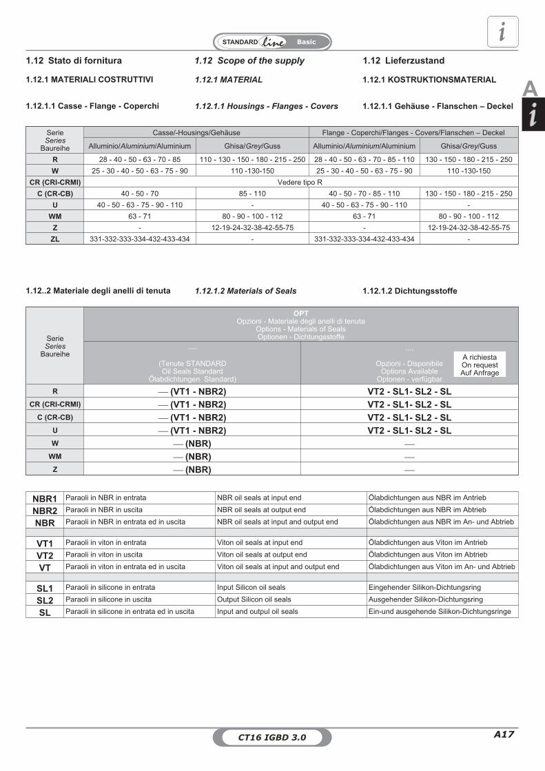
A17CT16 IGBD 3.0
Basic
A
1.12 Scope of the supply 1.12 Lieferzustand1.12 Stato di fornitura
1.12.1 MATERIALI COSTRUTTIVI 1.12.1 KOSTRUKTIONSMATERIAL1.12.1 MATERIAL
1.12.1.1 Casse - Flange - Coperchi 1.12.1.1 Gehäuse - Flanschen – Deckel1.12.1.1 Housings - Flanges - Covers
1.12..2 Materiale degli anelli di tenuta 1.12.1.2 Dichtungsstoffe1.12.1.2 Materials of Seals
SerieSeries
Baureihe
OPTOpzioni - Materiale degli anelli di tenuta
Options - Materials of SealsOptionen - Dichtungsstoffe
�
(Tenute STANDARDOil Seals Standard
Ölabdichtungen Standard)
....
Opzioni - DisponibileOptions Available
Optonen - verfügbar
R� (VT1 - NBR2) VT2 - SL1- SL2 - SL
CR (CRI-CRMI)� (VT1 - NBR2) VT2 - SL1- SL2 - SL
C (CR-CB)� (VT1 - NBR2) VT2 - SL1- SL2 - SL
U� (VT1 - NBR2) VT2 - SL1- SL2 - SL
W� (NBR) �
WM� (NBR) �
Z� (NBR) �
A richiestaOn requestAuf Anfrage
SerieSeries
Baureihe
Casse/-Housings/Gehäuse Flange - Coperchi/Flanges - Covers/Flanschen – Deckel
Alluminio/Aluminium/Aluminium Ghisa/Grey/Guss Alluminio/Aluminium/Aluminium Ghisa/Grey/Guss
R 28 - 40 - 50 - 63 - 70 - 85 110 - 130 - 150 - 180 - 215 - 250 28 - 40 - 50 - 63 - 70 - 85 - 110 130 - 150 - 180 - 215 - 250
W 25 - 30 - 40 - 50 - 63 - 75 - 90 110 -130-150 25 - 30 - 40 - 50 - 63 - 75 - 90 110 -130-150
CR (CRI-CRMI) Vedere tipo R
C (CR-CB) 40 - 50 - 70 85 - 110 40 - 50 - 70 - 85 - 110 130 - 150 - 180 - 215 - 250
U 40 - 50 - 63 - 75 - 90 - 110 - 40 - 50 - 63 - 75 - 90 - 110 -
WM 63 - 71 80 - 90 - 100 - 112 63 - 71 80 - 90 - 100 - 112
Z - 12-19-24-32-38-42-55-75 - 12-19-24-32-38-42-55-75
ZL 331-332-333-334-432-433-434 - 331-332-333-334-432-433-434 -
NBR1 Paraoli in NBR in entrata NBR oil seals at input end Ölabdichtungen aus NBR im Antrieb
NBR2 Paraoli in NBR in uscita NBR oil seals at output end Ölabdichtungen aus NBR im Abtrieb
NBR Paraoli in NBR in entrata ed in uscita NBR oil seals at input and output end Ölabdichtungen aus NBR im An- und Abtrieb
VT1 Paraoli in viton in entrata Viton oil seals at input end Ölabdichtungen aus Viton im Antrieb
VT2 Paraoli in viton in uscita Viton oil seals at output end Ölabdichtungen aus Viton im Abtrieb
VT Paraoli in viton in entrata ed in uscita Viton oil seals at input and output end Ölabdichtungen aus Viton im An- und Abtrieb
SL1 Paraoli in silicone in entrata Input Silicon oil seals Eingehender Silikon-Dichtungsring
SL2 Paraoli in silicone in uscita Output Silicon oil seals Ausgehender Silikon-Dichtungsring
SL Paraoli in silicone in entrata ed in uscita Input and outpul oil seals Ein-und ausgehende Silikon-Dichtungsringe

CT16 IGBD 3.0A18
Basic
1.12.2 Lubrificazione 1.12.2 Schmierung1.12.2 Lubrication
1.12 Scope of the supply 1.12 Lieferzustand1.12 Stato di fornitura
RIRMI
OPT1 - Opzioni - Stato fornitura olioOptions - Scope of the supply - Options - OIL
Optionen - Lieferzustand - Optionen - ÖlSigla ordine
Designation orderBezeichnung Bestellung
28
INOIL_STD4050637085
110
OUTOIL130150180215250
Lub
CRICRMI
OPT1 - Opzioni - Stato fornitura olioOptions - Scope of the supply - Options - OIL
Optionen - Lieferzustand - Optionen - ÖlSigla ordine
Designation orderBezeichnung Bestellung
28/28
INOIL_STD
28/4028/5028/6328/7040/4040/5040/6340/7040/8550/7050/85
50/11063/7063/85
63/11063/13070/85
70/11070/130
85/110
OUTOIL
85/13085/15085/180
110/150110/180110/215130/180130/250
CRCB
OPT1 - Opzioni - Stato fornitura olioOptions - Scope of the supply - Options - OIL
Optionen - Lieferzustand - Optionen - ÖlSigla ordine
Designation orderBezeichnung Bestellung
40INOIL_STD50
70
85
OUTOIL
110130150180215250
Lub
Lub
UIUMI
OPT1 - Opzioni - Stato fornitura olioOptions - Scope of the supply - Options - OIL
Optionen - Lieferzustand - Optionen - ÖlSigla ordine
Designation orderBezeichnung Bestellung
40
INOIL_STD50637560
110
Lub
WIWMI
OPT1 - Opzioni - Stato fornitura olioOptions - Scope of the supply - Options - OIL
Optionen - Lieferzustand - Optionen - ÖlSigla ordine
Designation orderBezeichnung Bestellung
25
INOIL_STD
304050637590
110OUTOIL130
150
Lub
WM
OPT1 - Opzioni - Stato fornitura olioOptions - Scope of the supply - Options - OIL
Optionen - Lieferzustand - Optionen - ÖlSigla ordine
Designation orderBezeichnung Bestellung
63
INOIL_STD718090
100112
ZL
OPT1 - Opzioni - Stato fornitura olioOptions - Scope of the supply - Options - OIL
Optionen - Lieferzustand - Optionen - ÖlSigla ordine
Designation orderBezeichnung Bestellung
331
INOIL_STD
332333334432433434
Lub
Z
OPT1 - Opzioni - Stato fornitura olioOptions - Scope of the supply - Options - OIL
Optionen - Lieferzustand - Optionen - ÖlSigla ordine
Designation orderBezeichnung Bestellung
12
OUTOIL
19243238425575
Lub

A19CT16 IGBD 3.0
Basic
A1.12.2 Lubrificazione 1.12.2 Schmierung1.12.2 Lubrication
1.12 Scope of the supply 1.12 Lieferzustand1.12 Stato di fornitura
Nota campo- ASOILNella targhetta sono riportate le seguentiinformazioni:- Code_Plate;- Sigla lubrificante;- ISO VG;- Type DIN;- NSF;- Altre prescrizioni.
Note range-ASOILThe type plate contains the following information:- Code_Plate- Lubricant type- ISO VG- Type DIN- NSF- other details
Hinweis Bereich-ASOILAuf dem Typenschild finden Sie folgendeInformationen:- Code_Plate- Schmiermitteltyp- ISO VG- Type DIN- NSF- andere Hinweise
ATTENZIONE:Lo stato di fornitura è messo in evidenzacon una targhetta adesiva posta sulriduttore.Verificare la corrispondenza tra stato difornitura e targhetta adesiva.
ACHTUNG:Der entsprechende Lieferzustand wird aufeinem Aufkleber am Getriebe angegeben.Überprüfen Sie die Übereinstimmung zwi-schen effektivem Lieferzustand und Auf-kleber.
CAUTION:Gearbox state of supply is indicated on anameplate applied on gearbox.Ensure that nameplate data and state ofsupply correspond.
OPT1 - Opzioni - Stato fornitura olio-Options - Scope of the supply - Options - OIL
Optionen - Lieferzustand - Optionen - ÖlStato fornituraScope of the supplyLieferzustand
Riduttore - LubrificazioneGearbox - LubrificationGetriebe - Schmierung
TipoTypeTyp
NOTENoteHinweis
TarghettaNamplateAufkleber
OUTOIL
Riduttore Privo di LubrificanteGearbox with no lubricantGetriebe ohne Schmiermittel
Si consiglia l'uso di oli a base sintetica.Vedere a tale proposito le indicazioni riportate paragrafo1.2 e 1.6.Tutti i riduttori con limitatore di coppia LC-LP-LF devono esserelubrificati ad olio: la lubrificazione a grasso non è ammessa.
The use of synthetic oil is recommended.see details in paragraph 1.2 and 1.6.All gearboxes incorporating torque limiters LC-LP-LF will have tobe lubricated with oil: grease lubrication is not admitted.
Der Einsatz von synthetischem Öl wird empfohlen.Siehe diesbezüglich die Hinweise im Abschnitt 1.2 und 1.6.Alle Getriebe mit Rutschkupplung LC-LP-LF müssen mit Ölgeschmiert werden: Eine Fettschmierung ist hier nicht zulässig.
Se richiesti completi dilubrificante, verranno forniti conolio standard - "INOIL_STD"
If customer requests supply ofgearbox with lubricant, we shallsupply - "INOIL_STD"
Falls diese Getriebe mitSchmiermittelfüllung angefordertwerden - "INOIL_STD"
INOIL_STD
Riduttore Completo di LubrificanteStandard STMGearbox with lubricant STM standardGetriebe mit Standard SchmiermittelSTM
RI-CRI-CR-UI-WI-ZOMALA S4 WE 320
OilGear_TYPECLP PGSynthetic PG
WI - Nothing namplate
WMSPIRAX S2 ATF AX
ATF_OilMineral WM - Look at 1.12.3
ZL331FG B 00b tamlith
Grease� Nothing
ZL332-333-334-432-433-434OMALA S2 G 100
OilGear_TYPECLP Mineral � Nothing
INOIL_Food
Riduttore Completo di Lubrificante"ALIMENTARE"Gearbox with lubricant "FOOD-TYPE"Getriebe mit Schmiermittel“LEBENSMITTEL”
RI-CRI-CR-UI-WI-ZKlüberoil 4 UH1 N 320
OilGear_TYPECLP HCE
Synthetic HCENSF H1
�
ASOIL
Riduttore Completo di LubrificanteSpeciale - a richiestaGearbox with Special lubricant - OnrequestGetriebe mit Sondern-Schmiermittel -Auf Anfrage
A richiestaOn requestAuf Anfrage
OilGear_TYPECLP PGSynthetic PG
�
OilGear_TYPECLP HCSynthetic PAOOilGear_TYPECLP Mineral
OilGear_TYPECLP HCESynthetic HCENSF H1Grease

CT16 IGBD 3.0A20
Basic
Worm gearboxes with a shielded bear-ing
Riduttori forniti con il cuscinettoschermato
Getrieben mit abgeschirmtem Lagergeliefert werden
TARGHETTA ALLEGATA AL VARIATORE MECCANICONAMEPLATE ON MECHANICAL VARIATOR
DEM MECHANISCHEN VERSTELLGETRIEBE BEIGEFÜGTES TYPENSCHILD
WM
1.12.2 Lubrificazione 1.12.2 Schmierung1.12.2 Lubrication
1.12 Scope of the supply 1.12 Lieferzustand1.12 Stato di fornitura
Se ne consiglia il ringrasaggioindipendentemente dalle ore di esercizioeffettuate, dopo almeno 2-3 anni.
Pertanto è stato predisposto uningrassatore per provvedere all’opportunoringrassaggio.
Le Caratteristiche tecniche generali delgrasso utilizzato sono:
- Inspessente: base di Litio;- NGLI: 2;- Olio: minerale con adittivazione EP diviscosità minima ISO VG 160;- Adittivi: l’olio presente nel grasso deveavere caratteristiche di adittivazione EP;
SPECIFICHE E APPROVAZIONI
ISO:L-X-BCHB 2DIN 51 825: KP2K -20
It is recommended to grease it at least ev-ery 2-3 years regardless of the operatinghours.
To this end it is provided with a greaser.
Following are the general technical fea-tures of the lubrication grease:
- Thickener: Lithium-based;- NGLI: 2;- Oil: mineral with EP additives with mini-mum viscosity as per ISO VG 160;- Additives: the oil in the grease mustfeature EP additive;
SPECIFICATIONS AND APPROVALS
ISO:L-X-BCHB 2DIN 51 825: KP2K -20
Wir empfehlen, unabhängig von denerfolgten Betriebsstunden, mindests alle2-3 Jahre ein entsprechendesNachschmieren.
Daher wurde ein angemessenerSchmiernippel für das Nachschmierenvorgesehen.
Allgemeine technische Eigenschaftendes verwendeten Fetts:
- Verdickungsmittel: auf Lithiumbasis;- NGLI: 2;- Öl: Mineralöl mit Zusatz von EP mitMindestviskosität gemäß ISO VG 160;- Additive: das im Fett enthaltene Öl mussdie Eigenschaften der EP Additivierungaufweisen;
SPEZIFIKATIONENISO:L-X-BCHB 2DIN 51 825: KP2K -20
1.12.3 VARIATORE MECCANICO 1.12.3 MECHANICAL VARIATOR 1.12.3 MECHANISCHESVERSTELLGETRIEBE
CT16 IGBD 3.0CT16 IGBD 3.1

A21CT16 IGBD 3.0
Basic
A1.12.4 Connessionemotore/riduttore con giuntoSTM/ROTEX
Qualora la connessione tra riduttore emacchina motrice sia effettuata con ungiunto è necessario verificare se è neces-sario montare un linguetta di dimensioni adisegno STM.La linguetta e la targhetta nella quale sonoriportate le istruzioni di montaggio sono al-legate ad ogni fornitura.Qualora non fornite segnalare il problemaal Nostro Ufficio Commerciale ed attenersialla presenti istruzioni per l'istallazione delmotore sul riduttore.Di seguito sono allegate targhette con lerelative istruzioni di montaggio.
1.12. Verbindung zwischen motorund getriebe über kupplung
STM/ROTEX
Bei Verbindung zwischen Getriebe undAntriebseinheit über eine Kupplung mussüberprüft werden, ob ein Federkeil gemäßSTM-Maßzeichnung erforderlich ist.Der Federkeil und das Schild, auf dem dieMontageanleitung wiedergegeben wird,sind im Lieferumfang enthalten.Sollten sie nicht mitgeliefert worden sein,muss dies unserer Verkaufsabteilung mit-geteilt werden. Für die Installation des Mo-tors am Getriebe muss man sich an dieentsprechenden Anleitungen halten.Auf den folgenden Seiten werden die Blättermit den entsprechenden Montageanleitungenangefügt.
1.12.4 Connecting the motorand gearbox withSTM/ROTEX joint
If gearbox and driving machine are con-nected by means of a joint, check whetherit is necessary to install a key sized asspecified on STM drawing.Key and nameplate indicating assemblyinstructions come with any supply.Should they be missing, report this prob-lem to our Sales Dept. and follow these in-structions for installing the motor togearbox.
Follow are showed some of the name-plates bearing the installation instructions
1.12 Scope of the supply 1.12 Lieferzustand1.12 Stato di fornitura
Giunto a disegno "STM"Joint to "STM" drawing
Kupplung gemäss "STM"-zeichnung
Connessione motore/riduttoreConnecting the motor/gearbox
Verbindung zwischen motor und GetriebeRMI 110 - PAM 132
Giunto a disegno "STM"Joint to "STM" drawing
Kupplung gemäss "STM"-zeichnung
Connessione motore/riduttoreConnecting the motor/gearbox
Verbindung zwischen motor und GetriebeRMI 110 - PAM 132
Tab. 1.13
Linguetta con dimensione hY diversa damisura unificata.I riduttori nei PAM riportati in tabella sonoforniti con allegata la linguetta con la di-mensione con dimensione ridotta.hY
FASI DI INSTALLAZIONE:A) Smontare il componente 2 (linguettaunificata) dal componente1 (motore elettri-co);B) Montare il componente 3 (linguetta for-nita STM) sull'albero del motore;C) Montare il componente 1 (motore elet-trico) su riduttore.
Special key having h Y dimension differentfrom standard.Gearboxes in the PAM versions specifiedin the chart are supplied with enclosed thespecial key having h Y reduced dimen-sion.
STEP INSTALLATIONA)Disassemble the component 2 (stan-dard key) from the component 1 ( electricmotor );B)Assemble component 3 (key suppliedby STM) on the motor shaft;C) Assemble component 1 (electric motor)to the gearbox
Passfeder mit Massen hY nicht nach Uninorm.Die Getriebe mit Iec wie nach Tabelle wer-den mit kleineren Passfedern (Mass hY)geliefert.
MONTAGEEinbauphasen:A)Einzelteil 2 (Passfeder nach UNI) vomEinzelteil 1(E-Motor) demontieren;B)Einzelteil 3(STM Passfeder) auf demMotor montierenC) Das Einzelteil 1 (E-Motor) auf das Ge-triebe montieren.
Prescrizioni di installazione del Motore
1.11 Installazione
con Riduttore RMI 110 PAM 132.
1.11 Installation
Procedure to assemble electric motor toGetriebeRMI110 IEC132
Tipo riduttoreGearbox typeGetriebe Typ
IEC dY EY
KeyStandard
(bY x hY x LY)
KeyFornitura STM
Supplied by STMSTM Lieferung
(bY x hY x LY)
RMI 110 132 38 80 10 x 8 x 70 10 x 7 x 70
Linguetta con dimensione hY diversa damisura unificata.I riduttori nei PAM riportati in tabella sonoforniti con allegata la linguetta con la di-mensione con dimensione ridotta.hY
FASI DI INSTALLAZIONE:A) Smontare il componente 2 (linguettaunificata) dal componente1 (motore elettri-co);B) Montare il componente 3 (linguetta for-nita STM) sulC) Montare il componente 1 (motore elet-trico) su riduttore.
Special key having h Y dimension differentfrom standard.Gearboxes in the PAM versions specifiedin the chart are supplied with enclosed thespecial key having h Y reduced dimen-sion.
STEP INSTALLATIONA)Disassemble the component 2 (stan-dard key) from the component 1 ( electricmotor );B)Assemble component 3 (key suppliedby STM) on the motor shaft;C) Assemble component 1 (electric motor)to the gearbox.
Passfeder mit Massen hY nicht nach Uninorm.Die Getriebe mit Iec wie nach Tabelle wer-den mit kleineren Passfedern (Mass hY)geliefert.
MONTAGEEinbauphasen:A)Einzelteil 2 (Passfeder nach UNI) vomEinzelteil 1(E-Motor) demontieren;B)Einzelteil 3(STM Passfeder) auf demMotor montieren;C) Das Einzelteil 1 (E-Motor) auf das Ge-triebe montieren.
dY
LY
LY
bY
hY
EY
3
1
2
CODICE TARGHETTA - CODE PLATE
1080031041
CODICE TARGHETTA - CODE PLATE1080031271
1.12.4 Installazione
Prescrizioni di installazione del Motorecon Riduttore.
1.12.4 Installation
Instructions for installing motor ongearbox.
Installation des Motors mit dem Getriebe.
1.12.4 Montage
Giunto a disegno STM / Coupling made to STM drawing / Kupplung gemäß STM-Zeichnung
CR
FASI DI INSTALLAZIONE:A1) UMI 40-50 - EX:
Montare il componente 1 applicandouna pressione manuale.Eventualmente usare un piccolomartello di plastica per agevolarel’inserimento del componente.
A2)UMI 75-90-110:63-
A2.1 - Nei riduttori con le predisposizioniriportate in figura, prima di procedere almontaggio del componente 1, allineare la sededella linguetta presente nel componente con lacorrispettiva sede presente nella vite senza fine.
A2.2 - Montare il componente 1 applicando unapressione manuale.Eventualmente usare un piccolo martello diplastica per agevolare l’inserimento delcomponente.
Per ulteriori informazioni contattare il Nostro UfficioTecnico.
Contact our Technical Dept. for more information Für weitere Informationen wenden Sie sich bitte anunsere Konstruktionsabteilung.
FASI DI SMONTAGGIOPrima di procedere allo smontaggio delmotore assicurarsi che il motore sia assicuratoad un sistema di sollevamento tramite cinghiaonde prevenire danni a persone o cose.Questo per evitare che durante lo smontaggiodelle viti di serraggio tra motore e riduttore il
motore posso cadere a terra.
B) Apporre un film di grasso sull’albero delmotore elettrico;C) Montare il motore elettrico sul riduttore eserrare le viti.
B) Apply grease on the electric motor shaft;
C) Assemble electric motor into the gearbox andtighten screws.
B) Fetten sie die Motorwelle des Elektromotorsein;C)Montieren sie Elektromotor am Getriebe undsichern sie die Schrauben.
INSTALLATION STEPS:A1) UMI 40-50 - EX:
Install part 1 by applying lightly pressure. If itwould be necessary, use a small plastic hammerto facilitate the insertion of the component.
A2)UMI 75-90-110:63-
A2.1 - For gearboxes with arrangementshown in the figure, before starting installation ofthe component 1, align the key groove in thiscomponent with the corresponding groove of theworm..
A2.2 - Install part 1 by applying lightly pressure. Ifit would be necessary, use a small plastichammer to facilitate the insertion of thecomponent.
A1)
MONTAGESCHRITTEUMI 40-50 - EX:
Der Einbau der Komponente 1 erfolgt mitleichtem, manuellem Druck. Verwenden Siegegebenenfalls einen kleinenKunststoffhammer, um das Einsetzen desBauteils zu erleichtern.
A2)UMI 75-90-110:63-
A2.1 - Bei Getrieben mit Vorbereitung, wieim Bild dargestellt, muss vor Einbau derKomponente 1 die Passfedernut entsprechendder Nut der Schneckenwelle ausgerichtetwerden.
A2.2 - Der Einbau der Komponente 1 erfolgt mitleichtem, manuellem Druck. Verwenden Siegegebenenfalls einen kleinenKunststoffhammer, um das Einsetzten desBauteils zu erleichtern.
DE-INSTALLATIONBefore starting de-installation, please assure that theengine is secured with a suitable hoist to prevent injuryor damage. This action is necessary because, withrelease of the locking screws between the gearbox andengine, the engine could fall to the ground.
DEMONTAGE
Bevor Sie mit der Demontage beginnen, stellen Siebitte sicher, dass der Motor mit einem geeignetenHebezeug vor Absturz gesichert ist, um Personen- undSachschäden zu verhindern.Diese Maßnahme istnotwendig, da bei Lösen der Spannschraubenzwischen Getriebe und Motor der Motor zu Boden fallenkönnte.
63-75-90-110
IEC 10075
IEC 11290
U
11
11
EX..
40-50UR CR
IEC 9063
NEMA 140C
IEC 132
NEMA 180C
110NEMA 210C
For additional information please referto STM maintenance booklet availableon our internet site:www.stmspa.com
Fuer weitere Auskünfte bitte STM War-tungshandbuch nachsehen. Es ist ininternet :www.stmspa.com
Per quanto non quì specificato, fare ri-ferimento al manuale d'uso e manuten-zione reperibile sul ns. sito Web:www.stmspa.com
CT16 IGBD 3.0CT16 IGBD 3.1
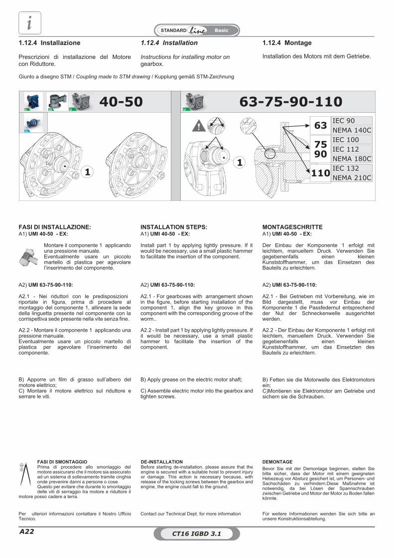
CT16 IGBD 3.0A22
Basic
1.12.4 Installazione
Prescrizioni di installazione del Motorecon Riduttore.
1.12.4 Installation
Instructions for installing motor ongearbox.
1.12.4 Montage
Installation des Motors mit dem Getriebe.
Giunto a disegno STM / Coupling made to STM drawing / Kupplung gemäß STM-Zeichnung
63-75-90-110
IEC 10075
IEC 11290
U
11
11
EX..
40-50UR CR
IEC 9063
NEMA 140C
IEC 132
NEMA 180C
110NEMA 210C
FASI DI INSTALLAZIONE:A1) UMI 40-50 - EX:
Montare il componente 1 applicandouna pressione manuale.Eventualmente usare un piccolomartello di plastica per agevolarel’inserimento del componente.
A2) UMI 63-75-90-110:
A2.1 - Nei riduttori con le predisposizioniriportate in figura, prima di procedere almontaggio del componente 1, allineare la sededella linguetta presente nel componente con lacorrispettiva sede presente nella vite senza fine.
A2.2 - Montare il componente 1 applicando unapressione manuale.Eventualmente usare un piccolo martello diplastica per agevolare l’inserimento delcomponente.
Per ulteriori informazioni contattare il Nostro UfficioTecnico.
Contact our Technical Dept. for more information Für weitere Informationen wenden Sie sich bitte anunsere Konstruktionsabteilung.
FASI DI SMONTAGGIOPrima di procedere allo smontaggio delmotore assicurarsi che il motore sia assicuratoad un sistema di sollevamento tramite cinghiaonde prevenire danni a persone o cose.Questo per evitare che durante lo smontaggiodelle viti di serraggio tra motore e riduttore il
motore posso cadere a terra.
B) Apporre un film di grasso sull’albero delmotore elettrico;C) Montare il motore elettrico sul riduttore eserrare le viti.
B) Apply grease on the electric motor shaft;
C) Assemble electric motor into the gearbox andtighten screws.
B) Fetten sie die Motorwelle des Elektromotorsein;C)Montieren sie Elektromotor am Getriebe undsichern sie die Schrauben.
INSTALLATION STEPS:A1) UMI 40-50 - EX:
Install part 1 by applying lightly pressure. If itwould be necessary, use a small plastic hammerto facilitate the insertion of the component.
A2) UMI 63-75-90-110:
A2.1 - For gearboxes with arrangement shownin the figure, before starting installation of thecomponent 1, align the key groove in thiscomponent with the corresponding groove of theworm..
A2.2 - Install part 1 by applying lightly pressure. Ifit would be necessary, use a small plastichammer to facilitate the insertion of thecomponent.
MONTAGESCHRITTEA1) UMI 40-50 - EX:
Der Einbau der Komponente 1 erfolgt mitleichtem, manuellem Druck. Verwenden Siegegebenenfalls einen kleinenKunststoffhammer, um das Einsetzen desBauteils zu erleichtern.
A2) UMI 63-75-90-110:
A2.1 - Bei Getrieben mit Vorbereitung, wie imBild dargestellt, muss vor Einbau derKomponente 1 die Passfedernut entsprechendder Nut der Schneckenwelle ausgerichtetwerden.
A2.2 - Der Einbau der Komponente 1 erfolgt mitleichtem, manuellem Druck. Verwenden Siegegebenenfalls einen kleinenKunststoffhammer, um das Einsetzten desBauteils zu erleichtern.
DE-INSTALLATIONBefore starting de-installation, please assure that theengine is secured with a suitable hoist to prevent injuryor damage. This action is necessary because, withrelease of the locking screws between the gearbox andengine, the engine could fall to the ground.
DEMONTAGE
Bevor Sie mit der Demontage beginnen, stellen Siebitte sicher, dass der Motor mit einem geeignetenHebezeug vor Absturz gesichert ist, um Personen- undSachschäden zu verhindern.Diese Maßnahme istnotwendig, da bei Lösen der Spannschraubenzwischen Getriebe und Motor der Motor zu Boden fallenkönnte.
CT16 IGBD 3.0CT16 IGBD 3.1

A23CT16 IGBD 3.0
Basic
ATab. 1.13
Linguetta con dimensione hY diversa damisura unificata.I riduttori nei PAM riportati in tabella sonoforniti con allegata la linguetta con la di-mensione hY con dimensione ridotta.
FASI DI INSTALLAZIONE:A) Smontare il componente 2 (linguettaunificata) dal componente1 (motore elettri-co);B) Montare il componente 3 (linguetta for-nita STM) sull'albero del motore;C) Montare il componente 1 (motore elet-trico) su riduttore.
Special key having h Y dimension differentfrom standard.Gearboxes in the PAM versions specifiedin the chart are supplied with enclosed thespecial key having h Y reduced dimen-sion.
STEP INSTALLATIONA)Disassemble the component 2 (stan-dard key) from the component 1 ( electricmotor );B)Assemble component 3 (key suppliedby STM) on the motor shaft;C) Assemble component 1 (electric motor)to the gearbox
Passfeder mit Massen hY nicht nach Uninorm.Die Getriebe mit Iec wie nach Tabelle wer-den mit kleineren Passfedern (Mass hY)geliefert.
MONTAGEEinbauphasen:A)Einzelteil 2 (Passfeder nach UNI) vomEinzelteil 1(E-Motor) demontieren;B)Einzelteil 3(STM Passfeder) auf demMotor montierenC) Das Einzelteil 1 (E-Motor) auf das Ge-triebe montieren.
1.12.4 Installazione
Prescrizioni di installazione del Motorecon Riduttore RMI 110 PAM 132.
1.12.4 Installation
Procedure to assemble electric motor toGearbox RMI110 PAM132
1.12.4 Montage
Vorschriften für Einbau des Motors anGetriebe RMI110 IEC132
Tipo riduttoreGearbox typeGetriebe Typ
IEC dY EY
KeyStandard
(bY x hY x LY)
KeyFornitura STM
Supplied by STMSTM Lieferung
(bY x hY x LY)
RMI 110 132 38 80 10 x 8 x 70 10 x 7 x 70
Linguetta con dimensione hY diversa damisura unificata.I riduttori nei PAM riportati in tabella sonoforniti con allegata la linguetta con la di-mensione hY con dimensione ridotta.
FASI DI INSTALLAZIONE:A) Smontare il componente 2 (linguettaunificata) dal componente1 (motore elettri-co);B) Montare il componente 3 (linguetta for-nita STM) sulC) Montare il componente 1 (motore elet-trico) su riduttore.
Special key having h Y dimension differentfrom standard.Gearboxes in the PAM versions specifiedin the chart are supplied with enclosed thespecial key having h Y reduced dimen-sion.
STEP INSTALLATIONA)Disassemble the component 2 (stan-dard key) from the component 1 ( electricmotor );B)Assemble component 3 (key suppliedby STM) on the motor shaft;C) Assemble component 1 (electric motor)to the gearbox.
Passfeder mit Massen hY nicht nach Uninorm.Die Getriebe mit Iec wie nach Tabelle wer-den mit kleineren Passfedern (Mass hY)geliefert.
MONTAGEEinbauphasen:A)Einzelteil 2 (Passfeder nach UNI) vomEinzelteil 1(E-Motor) demontieren;B)Einzelteil 3(STM Passfeder) auf demMotor montieren;C) Das Einzelteil 1 (E-Motor) auf das Ge-triebe montieren.
dY
LY
LY
bY
hY
EY
3
1
2
CT16 IGBD 3.0CT16 IGBD 3.1

CT16 IGBD 3.0A24
Basic
1.13 Normative applicate 1.13 Angewendete Normen1.13 Standards applied
A24A24
1.11.2 Spezifikationen für"ATEX"-produkte
AnwendungsbereichDie ATEX-Richtlinie (2014/34/UE) wird beielektrischen und nicht elektrischen Produk-ten angewendet, die dazu bestimmt sind, inpotentiell explosionsfähigen Atmosphäreneingesetzt und betrieben zu werden. Die po-tentiell explosionsfähigen Atmosphären wer-den in Abhängigkeit der Wahrscheinlichkeitin Gruppen und Zonen unterteilt. DieSTM-Produkte entsprechen der folgenden
1.11.2 Specifications of "ATEX"products
Application fieldATEX set of provisions (2014/34/UE) isreferred to electric and non-electric pro-ducts which are used and run in a poten-tially explosive environment. Thepotentially explosive environments are di-vided into different groups and zones ac-cording to the probability of theirformation. STM products are in conformitywith following classification:
1.11.2 Specifiche prodotti “ATEX”
Campo applicabilitàLa direttiva ATEX (2014/34/UE) si applicaa prodotti elettrici e non elettrici destinati aessere introdotti e svolgere la loro funzio-ne in atmosfera potenzialmente esplosiva.Le atmosfere potenzialmente esplosivevengono suddivise in gruppi e zone a se-conda della probabilità di formazione. Iprodotti STM sono Conformi alla seguenteclassificazione:
1.13.1 Specifiche prodotti non “ATEX”
I riduttori della STM SpA sono organi meccanicidestinati all’uso industriale e all’incorporazionein apparecchiature meccaniche più complesse.Dunque non vanno considerati macchineindipendente per una predeterminataapplicazione ai sensi 2006/42/CE, né tantomenodispositivi di sicurezza.
1.11.1 Specifications of non - "ATEX"products
STM SpA gearboxes are mechanical devices forindustrial use and incorporation in more complexmachines. Consequently, they should not beconsidered neither self-standing machines for apre-determined application according to2006/42/CE nor safety devices.
1.11.1 Spezifikationen für produkte,die nicht der "ATEX"-normentsprechen
Bei den Getrieben der STM SpA handelt es sichum Mechanikorgane, die für den industriellenEinsatz und einen Einbau in komplexereEinrichtungen bestimmt sind. Sie werdendeshalb weder unter dem Aspekt unabhängiger,für eine bestimmte Anwendung vorgesehenerMaschinen im Sinne der 2006/42/CE, noch alsSicherheitsvorrichtungen berück- sichtigt.
Nel caso di classe di temperatura T5 occorreverificare la potenza limite termicodeclassata (rif. normativa internaNORM_0198, visionabile sul sito web:www.stmspa.com).
I prodotti del gruppo IID (atmosfera polverosa)vengono definiti dalla massima temperatura disuperficie effettiva.
La massima temperatura di superficie èdeterminata in normali condizioni di installazionee ambientali (–20°C e +40°C) e senza depositi dipolvere sugli apparecchi.Qualunque scostamento da queste condizioni diriferimento può influenzare notevolmente losmaltimento del calore e quindi la temperatura.
In case of T5 temperature class it will benecessary to verify the declassed thermallimit power (refer to internal standardNORM_0198, available on the web site:www.stmspa.com).
The products of the family IID (dust envi-ronment) are defined by the max effectivesurface temperature.
Max surface temperature is determined instandard installation and environmentalconditions ( -20°C and +40°C ) and in ab-sence of dust on product surface.Any other condition will modify the heatdissipation and consequently the temper-
Bei der Temperaturklasse T5 muss diedeklassierte thermische Grenzleistungüberprüft werden (Bezug auf firmeninterneNORM_0198, abrufbar aus der Website:www.stmspa.com.
Die der Gruppe IID (Atmosphäre mitstaubförmiger Belastung) angehörigen Produktewerden ihrer effektiven maximalenOberflächentemperatur gemäß definiert.Die maximale Oberflächentemperatur wird innormalen Einbau- und Umgebungsbedingungen(-20°C und +40°C) und ohne auf den Vorrichtungenvorhandenen Staubablagerungen bestimmt.Jegliche Abweichung von diesenBezugsbedingungen kann sich erheblich auf dieWärmeableitung bzw. auf dieBetriebstemperatur auswirken.
Type Mark - standardDesignationType Mark Material Symbol Mark Group Category Symbol
Protection
GroupDangerous
materialTemperature Protection
level EPL Use limitation
Gb-4
GASII 2G Exh IIC T4 Gb -Gb-5 T5*
Gc-4 II 3G Exh IIC T4 Gc -Gc-5 T5*
Db-4
DUSTII 2D2D Exh IIIC 135 °C Db -Db-5 100 °C*
Dc-4 II 3D Exh IIIC 135 °C Dc -Dc-5 100 °C*
(*) ATEX temperature class on request
Type Mark - with limitation
Limitation Material DesignationType Mark Category
Groupdangerous
materialNOTE
ProductsVersions
Versions with compact motor � � � � All versions are excluded from certification
WM�
�� �
WI-WMI GASDUST
Gc-4 - Gc-5Dc-4 - Dc-5 3G
3D Standard
�
AccessoryOption
Torque limiter type: LP-LC.LFProduct R-CR-C
GASDUST
Gc-4-x - Gc-5-xDc-4-x - Dc-5-x
3G3D
with limitation Use x
Ventilation system And/OrPainting type: TYP3 - TYP4 *
GASGAS
b_Gb-4 - b_Gb-5b_Gc-4 - b_Gc-5 Standard IIB
*For other type painting:Type Mark is StandardOn request in available painting type for IIC:TYP3C & TYP4C
WM
W

A25CT16 IGBD 3.0
Basic
A
1.13 Normative applicate 1.13 Angewendete Normen1.13 Standards applied
1.13.5 UE Directives-CE mark-ISO 9001
Directive 2014/35/UE Low VoltageSTMgeared motors, right angle drives with motor,motovariators and electric motors meet the spe-cification of the low voltage directive.
2014/30/UE Electromagnetic Compatibility
STM geared motors, right angle drives with
motor, motovariators and electric motors corre-
spond to the specifications of the EMC directi-
ve.
Machinery Directive 2006/42/CE
STM geared motors, right angle drives with mo-
tor, motovariators and electric motors are not
standalone machines, they are exclusively for
installation into a machine or for assembly on a
machine.
CE Mark, Conformity Declarations and Ma-
nufacturer’s Declaration.
STM geared motors, right angle drives with mo-
tor, motovariators and electric motors carry the
CE Mark.
It indicates conformity to the low voltage directi-
ve and to electromagnetic compatibility directi-
ve.
On request STM supplies both the conformity
declarations and the manufacturer’s declaration
according to the machine directive.
ISO 9001
STM products have been designed and manu-
factured according to ISO 9001 quality system
standard.
On request a copy of the certification can be is-
sued.
1.13.5 UE-Richtlinien - CE-Zeichen- ISO9001
Niederspannungsrichtlinie. 2014/35/UEDie Getriebemotoren, Winkelgetriebe, Verstel-lgetriebe und Elektromotoren der STM entspre-chen den Vorschriften derNiederspannungsrichtlinie.
2014/30/UE Elektromagnetische Verträglic-hkeitDie Getriebemotoren, Winkelgetriebe, Verstel-lgetriebe und Elektromotoren der STM entspre-chen den Vorschriften der Richtlinie zurElektromagnetischen Verträglichkeit.
Maschinenrichtlinie 2006/42/CEDie Getriebemotoren, Winkelgetriebe, Verstel-lgetriebe und Elektromotoren der STM sind kei-ne Maschinen sondern Organe, die inMaschinen eingebaut oder an diesen montiertwerden.
CE-Zeichen, Hersteller- und Konformitäts-erklärungDie Getriebemotoren, Verstellgetriebe undElektromotoren tragen das CE-Zeichen.
Dieses Zeichen weist auf ihre Konformität mitder Niederspannungsrichtlinie und der Richtli-nie zur Elektromagnetischen Verträglichkeithin.Auf Anfrage kann die STM die Konfor-mitätserklärung und die Hersteller- erklärunggemäß Maschinenrichtlinie zu den Produktenliefern.
ISO 9001Die STM-Produkte werden in einem Qua-litätssystem gemäß dem Standard ISO 9001realisiert. Auf Anfrage kann daher eine Kopieder Zertifizierung geliefert werden.
1.13.5 UE Direttive - marcatura CE- ISO9001
Direttiva Bassa Tensione 2014/35/UEI motoriduttori, motorinvii angolari, motovariatorie i motori elettrici STM sono conformi alle prescri-zioni della direttiva Bassa Tensione .
2014/30/UE Compatibilità elettromagneticaI motoriduttori, motoriviiangolari, motovariatori e imotori elettrici STM sono conformi alle specifi-che della direttiva di Compatibilità Elettromagne-tica.
Direttiva Macchine 2006/42/CEI motoriduttori, motoriviiangolari, motovariatori e imotori elettrici STM non sono macchine ma orga-ni da installare o assemblare nelle macchine.
Marchio CE, dichiarazione del fabbricante edichiarazione di conformità.
I motoriduttori, motovariatori e i motori elet- tricihanno il marchio CE.Questo marchio indica la loro conformità alla di-rettiva Bassa Tensione e alla direttiva Compati-bilità Elettromagnetica.Su richiesta, STM può fornire la dichiarazionedi conformità dei prodotti e la dichiarazione delfabbricante secondo la direttiva macchine.
ISO 9001I prodotti STM sono realizzati all’interno di unsistema di qualità conforme allo standard ISO9001. A tal fine su richiesta è possibile rilascia-re copia del certificato.
1.13.4. COME SI APPLICAAl momento di una richiesta di offerta per prodottoconforme a normativa ATEX 2014/34/UE occorrecompilare la scheda acquisizione dati
(www.stmspa.com).Effettuare le verifiche come prima descritto.I riduttori certificati verranno consegnati con:-una seconda targhetta contenente i dati ATEX;-ove previsto un tappo sfiato, tappo sfiato con mollainterna;-se rispondente alla classe di temperatura T4 e T5 verràallegato un indicatore di temperatura (132 °C nel caso diT4 e 99°C rispettivamente per la T5)-Indicatore di temperatura : termometro a singolorilevamento, una volta raggiunta la temperatura indicatasi annerisce segnalando il raggiungimento di tale limite.
THERMAX
132 270°C °F
THERMAX
99 210°C °F
1.13.4. ANWENDUNGSWEISEBei einer Angebotsanfrage für der Richtlinie ATEX2014/34/UE entsprechende Produkte muss dasDatenerfassungsformular(www.stmspa.com) ausgefüllt werden.
Dazu die zuvor beschriebenen Kontrollen vornehmen.Die zertifizierten Getriebe werden wie folgt ausgestattetgeliefert: -mit einem zweiten Typenschild mit ATEX-Daten;-wo vorgesehen, mit einem Entlüftungs- verschluss,Entlüftungsverschluss mit interner Feder;-falls der Temperaturklasse T4 und T5 entsprechend,wird eine Temperaturanzeige vorgesehen (132 °C beiT4 und 99°C bei T5)-Temperaturanzeige: einzelnes Erfassungs-thermometer - bei Erreichen der angegebenenTemperatur wechselt die Farbe zur Anzeige dererreichten Temperatur in Schwarz.
1.13.4. HOW IS IT APPLIED
In case of request of offer relating to any product in con-
formity with the provisions ATEX/2014/34/UE, the
specifications paper should be filled in
(www.stmspa.com).
Perform the inspections as described above. Certified
reducers will be delivered with:
- a second nameplate containing ATEX data;
- a breather valve with internal spring, where a breather
is needed;
- if in accordance with classes of temperature T4 and
T5, a temperature gauge will be included (132 °C in
case of T4 and 99 °C in case of T5).
- Temperature gauge: single-reading thermometer, it
blackens once temperature is reached, pointing out the
achievement of that limit.
CT16 IGBD 3.0CT16 IGBD 3.1

CT16 IGBD 3.0A26
Basic
1.13 Normative applicate 1.13 Angewendete Normen1.13 Standards applied
1.13.6 Normative riferimentoProgettazione e Fabbricazione
1.13.6 Bezugsnormen Entwicklung undProduktion
1.13.6 Standards applied
Tutti i prodotti della STM sono progettatinel rispetto delle seguenti normative:
Calcolo degli ingranaggi e cuscinetti
ISO 6336Calcolo della capacità di carico degli in-granaggi cilindrici.
BS 721Calcolo della capacità di carico delle viti edelle corone elicoidali.
ISO 281Calcolo della durata a fatica dei cuscinettivolventi.
AlberiDIN 743Calcolo della durata a fatica degli alberi
Materiali
EN 10084Acciaio da cementazione per ingranaggi eviti senza fine.
EN 10083Acciaio da bonifica per alberi.
UNI EN 1982Bronzo per corone elicoidali.
UNI EN 1706Alluminio e leghe di Alluminio
UNI EN 1561Fusioni in ghisa grigia.
UNI EN 1563 2004Getti di ghisa a grafite sferoidale
UNI 3097Acciaio per cuscinetti per piste rotolamen-to.
All STM products are designed followingthese standards:
Calculation of gearboxes and bearings
ISO 6336:Calculation of load capacity of spur andhelical gears
BS 721:Calculation of load capacity for worm gea-ring.
ISO 281:Rolling bearings — Dynamic load ratingsand rating life
ShaftsDIN743Shafts — Dynamic load ratings and ratinglife
Materials
EN 10084Case hardening steels for gears andworms
EN 10083Quenched and Tempered Steels for shafts
UNI EN 1982Copper for helical worm-gears
UNI EN 1706Aluminium alloy
UNI EN 1561Grey iron casting
UNI EN 1563 2004Spheroidal cast iron
UNI 3097Ball and roller bearing steel
Alle Produkte der STM werden unter Ein-haltung folgender Normen entwickelt:
Berechnung der Zahnräder und Lager
ISO 6336Berechnung der Belastungsfähigkeit derzylindrischen Zahnräder.
BS 721Berechnung der Belastungsfähigkeit derSchnecken und Schrägzahnräder.
ISO 281Berechnung der Belastungsdauer derWälzlager.
WellenDIN743Berechnung der Belastungsdauer derWellen.
Material
EN 10084Einsatzstahl für Zahnräder und Schnec-ken.
EN 10083Vergütungsstahl für Wellen.
UNI EN 1982Bronze für Schrägzahnräder
UNI EN 1706Aluminium und Aluminiumlegierungen
UNI EN 1561Grauguss-Legierungen
UNI EN 1563 2004Sphäroguss
UNI 3097Stahl für Lagergleitbahnen